EP4082873A1 - Vehicle - Google Patents
Vehicle Download PDFInfo
- Publication number
- EP4082873A1 EP4082873A1 EP20906117.5A EP20906117A EP4082873A1 EP 4082873 A1 EP4082873 A1 EP 4082873A1 EP 20906117 A EP20906117 A EP 20906117A EP 4082873 A1 EP4082873 A1 EP 4082873A1
- Authority
- EP
- European Patent Office
- Prior art keywords
- vehicle
- roll
- angle
- torque
- vehicle body
- Prior art date
- Legal status (The legal status is an assumption and is not a legal conclusion. Google has not performed a legal analysis and makes no representation as to the accuracy of the status listed.)
- Pending
Links
- 230000001133 acceleration Effects 0.000 claims abstract description 119
- 230000005484 gravity Effects 0.000 claims abstract description 54
- 230000007423 decrease Effects 0.000 claims description 18
- 238000000034 method Methods 0.000 description 42
- 230000008569 process Effects 0.000 description 25
- 230000007246 mechanism Effects 0.000 description 23
- 239000000725 suspension Substances 0.000 description 23
- 238000010586 diagram Methods 0.000 description 18
- 230000008859 change Effects 0.000 description 17
- 230000001276 controlling effect Effects 0.000 description 11
- 230000006870 function Effects 0.000 description 7
- 230000015654 memory Effects 0.000 description 7
- 238000013459 approach Methods 0.000 description 6
- NJPPVKZQTLUDBO-UHFFFAOYSA-N novaluron Chemical compound C1=C(Cl)C(OC(F)(F)C(OC(F)(F)F)F)=CC=C1NC(=O)NC(=O)C1=C(F)C=CC=C1F NJPPVKZQTLUDBO-UHFFFAOYSA-N 0.000 description 4
- 230000010355 oscillation Effects 0.000 description 4
- 239000006096 absorbing agent Substances 0.000 description 3
- 230000002596 correlated effect Effects 0.000 description 3
- 230000000875 corresponding effect Effects 0.000 description 3
- 230000035939 shock Effects 0.000 description 3
- 230000006399 behavior Effects 0.000 description 2
- 230000008878 coupling Effects 0.000 description 2
- 238000010168 coupling process Methods 0.000 description 2
- 238000005859 coupling reaction Methods 0.000 description 2
- 239000002184 metal Substances 0.000 description 2
- 229910052751 metal Inorganic materials 0.000 description 2
- 238000012986 modification Methods 0.000 description 2
- 230000004048 modification Effects 0.000 description 2
- 230000002269 spontaneous effect Effects 0.000 description 2
- 238000004364 calculation method Methods 0.000 description 1
- 238000002485 combustion reaction Methods 0.000 description 1
- 238000004590 computer program Methods 0.000 description 1
- 239000012530 fluid Substances 0.000 description 1
- 238000007620 mathematical function Methods 0.000 description 1
- 239000003921 oil Substances 0.000 description 1
- 230000009467 reduction Effects 0.000 description 1
- 239000011347 resin Substances 0.000 description 1
- 229920005989 resin Polymers 0.000 description 1
- 102220184965 rs117987946 Human genes 0.000 description 1
- 229910052710 silicon Inorganic materials 0.000 description 1
- 239000010703 silicon Substances 0.000 description 1
- 230000003068 static effect Effects 0.000 description 1
- 230000007704 transition Effects 0.000 description 1
Images


Classifications
-
- B—PERFORMING OPERATIONS; TRANSPORTING
- B62—LAND VEHICLES FOR TRAVELLING OTHERWISE THAN ON RAILS
- B62D—MOTOR VEHICLES; TRAILERS
- B62D6/00—Arrangements for automatically controlling steering depending on driving conditions sensed and responded to, e.g. control circuits
-
- B—PERFORMING OPERATIONS; TRANSPORTING
- B62—LAND VEHICLES FOR TRAVELLING OTHERWISE THAN ON RAILS
- B62K—CYCLES; CYCLE FRAMES; CYCLE STEERING DEVICES; RIDER-OPERATED TERMINAL CONTROLS SPECIALLY ADAPTED FOR CYCLES; CYCLE AXLE SUSPENSIONS; CYCLE SIDE-CARS, FORECARS, OR THE LIKE
- B62K5/00—Cycles with handlebars, equipped with three or more main road wheels
- B62K5/10—Cycles with handlebars, equipped with three or more main road wheels with means for inwardly inclining the vehicle body on bends
-
- B—PERFORMING OPERATIONS; TRANSPORTING
- B62—LAND VEHICLES FOR TRAVELLING OTHERWISE THAN ON RAILS
- B62D—MOTOR VEHICLES; TRAILERS
- B62D6/00—Arrangements for automatically controlling steering depending on driving conditions sensed and responded to, e.g. control circuits
- B62D6/002—Arrangements for automatically controlling steering depending on driving conditions sensed and responded to, e.g. control circuits computing target steering angles for front or rear wheels
- B62D6/003—Arrangements for automatically controlling steering depending on driving conditions sensed and responded to, e.g. control circuits computing target steering angles for front or rear wheels in order to control vehicle yaw movement, i.e. around a vertical axis
-
- B—PERFORMING OPERATIONS; TRANSPORTING
- B60—VEHICLES IN GENERAL
- B60W—CONJOINT CONTROL OF VEHICLE SUB-UNITS OF DIFFERENT TYPE OR DIFFERENT FUNCTION; CONTROL SYSTEMS SPECIALLY ADAPTED FOR HYBRID VEHICLES; ROAD VEHICLE DRIVE CONTROL SYSTEMS FOR PURPOSES NOT RELATED TO THE CONTROL OF A PARTICULAR SUB-UNIT
- B60W30/00—Purposes of road vehicle drive control systems not related to the control of a particular sub-unit, e.g. of systems using conjoint control of vehicle sub-units
- B60W30/02—Control of vehicle driving stability
- B60W30/04—Control of vehicle driving stability related to roll-over prevention
-
- B—PERFORMING OPERATIONS; TRANSPORTING
- B60—VEHICLES IN GENERAL
- B60W—CONJOINT CONTROL OF VEHICLE SUB-UNITS OF DIFFERENT TYPE OR DIFFERENT FUNCTION; CONTROL SYSTEMS SPECIALLY ADAPTED FOR HYBRID VEHICLES; ROAD VEHICLE DRIVE CONTROL SYSTEMS FOR PURPOSES NOT RELATED TO THE CONTROL OF A PARTICULAR SUB-UNIT
- B60W30/00—Purposes of road vehicle drive control systems not related to the control of a particular sub-unit, e.g. of systems using conjoint control of vehicle sub-units
- B60W30/02—Control of vehicle driving stability
- B60W30/045—Improving turning performance
-
- B—PERFORMING OPERATIONS; TRANSPORTING
- B60—VEHICLES IN GENERAL
- B60W—CONJOINT CONTROL OF VEHICLE SUB-UNITS OF DIFFERENT TYPE OR DIFFERENT FUNCTION; CONTROL SYSTEMS SPECIALLY ADAPTED FOR HYBRID VEHICLES; ROAD VEHICLE DRIVE CONTROL SYSTEMS FOR PURPOSES NOT RELATED TO THE CONTROL OF A PARTICULAR SUB-UNIT
- B60W40/00—Estimation or calculation of non-directly measurable driving parameters for road vehicle drive control systems not related to the control of a particular sub unit, e.g. by using mathematical models
- B60W40/10—Estimation or calculation of non-directly measurable driving parameters for road vehicle drive control systems not related to the control of a particular sub unit, e.g. by using mathematical models related to vehicle motion
- B60W40/112—Roll movement
-
- B—PERFORMING OPERATIONS; TRANSPORTING
- B62—LAND VEHICLES FOR TRAVELLING OTHERWISE THAN ON RAILS
- B62D—MOTOR VEHICLES; TRAILERS
- B62D61/00—Motor vehicles or trailers, characterised by the arrangement or number of wheels, not otherwise provided for, e.g. four wheels in diamond pattern
- B62D61/06—Motor vehicles or trailers, characterised by the arrangement or number of wheels, not otherwise provided for, e.g. four wheels in diamond pattern with only three wheels
- B62D61/08—Motor vehicles or trailers, characterised by the arrangement or number of wheels, not otherwise provided for, e.g. four wheels in diamond pattern with only three wheels with single front wheel
-
- B—PERFORMING OPERATIONS; TRANSPORTING
- B62—LAND VEHICLES FOR TRAVELLING OTHERWISE THAN ON RAILS
- B62D—MOTOR VEHICLES; TRAILERS
- B62D9/00—Steering deflectable wheels not otherwise provided for
- B62D9/02—Steering deflectable wheels not otherwise provided for combined with means for inwardly inclining vehicle body on bends
-
- B—PERFORMING OPERATIONS; TRANSPORTING
- B62—LAND VEHICLES FOR TRAVELLING OTHERWISE THAN ON RAILS
- B62J—CYCLE SADDLES OR SEATS; AUXILIARY DEVICES OR ACCESSORIES SPECIALLY ADAPTED TO CYCLES AND NOT OTHERWISE PROVIDED FOR, e.g. ARTICLE CARRIERS OR CYCLE PROTECTORS
- B62J45/00—Electrical equipment arrangements specially adapted for use as accessories on cycles, not otherwise provided for
- B62J45/40—Sensor arrangements; Mounting thereof
- B62J45/41—Sensor arrangements; Mounting thereof characterised by the type of sensor
- B62J45/415—Inclination sensors
- B62J45/4151—Inclination sensors for sensing lateral inclination of the cycle
-
- B—PERFORMING OPERATIONS; TRANSPORTING
- B60—VEHICLES IN GENERAL
- B60W—CONJOINT CONTROL OF VEHICLE SUB-UNITS OF DIFFERENT TYPE OR DIFFERENT FUNCTION; CONTROL SYSTEMS SPECIALLY ADAPTED FOR HYBRID VEHICLES; ROAD VEHICLE DRIVE CONTROL SYSTEMS FOR PURPOSES NOT RELATED TO THE CONTROL OF A PARTICULAR SUB-UNIT
- B60W2300/00—Indexing codes relating to the type of vehicle
- B60W2300/34—Compact city vehicles, e.g., microcars or kei cars
- B60W2300/345—Three wheelers not including single track vehicles
-
- B—PERFORMING OPERATIONS; TRANSPORTING
- B60—VEHICLES IN GENERAL
- B60W—CONJOINT CONTROL OF VEHICLE SUB-UNITS OF DIFFERENT TYPE OR DIFFERENT FUNCTION; CONTROL SYSTEMS SPECIALLY ADAPTED FOR HYBRID VEHICLES; ROAD VEHICLE DRIVE CONTROL SYSTEMS FOR PURPOSES NOT RELATED TO THE CONTROL OF A PARTICULAR SUB-UNIT
- B60W2300/00—Indexing codes relating to the type of vehicle
- B60W2300/36—Cycles; Motorcycles; Scooters
- B60W2300/367—Tricycles
-
- B—PERFORMING OPERATIONS; TRANSPORTING
- B60—VEHICLES IN GENERAL
- B60W—CONJOINT CONTROL OF VEHICLE SUB-UNITS OF DIFFERENT TYPE OR DIFFERENT FUNCTION; CONTROL SYSTEMS SPECIALLY ADAPTED FOR HYBRID VEHICLES; ROAD VEHICLE DRIVE CONTROL SYSTEMS FOR PURPOSES NOT RELATED TO THE CONTROL OF A PARTICULAR SUB-UNIT
- B60W2720/00—Output or target parameters relating to overall vehicle dynamics
- B60W2720/18—Roll
-
- B—PERFORMING OPERATIONS; TRANSPORTING
- B62—LAND VEHICLES FOR TRAVELLING OTHERWISE THAN ON RAILS
- B62K—CYCLES; CYCLE FRAMES; CYCLE STEERING DEVICES; RIDER-OPERATED TERMINAL CONTROLS SPECIALLY ADAPTED FOR CYCLES; CYCLE AXLE SUSPENSIONS; CYCLE SIDE-CARS, FORECARS, OR THE LIKE
- B62K5/00—Cycles with handlebars, equipped with three or more main road wheels
- B62K5/02—Tricycles
- B62K5/027—Motorcycles with three wheels
-
- Y—GENERAL TAGGING OF NEW TECHNOLOGICAL DEVELOPMENTS; GENERAL TAGGING OF CROSS-SECTIONAL TECHNOLOGIES SPANNING OVER SEVERAL SECTIONS OF THE IPC; TECHNICAL SUBJECTS COVERED BY FORMER USPC CROSS-REFERENCE ART COLLECTIONS [XRACs] AND DIGESTS
- Y02—TECHNOLOGIES OR APPLICATIONS FOR MITIGATION OR ADAPTATION AGAINST CLIMATE CHANGE
- Y02T—CLIMATE CHANGE MITIGATION TECHNOLOGIES RELATED TO TRANSPORTATION
- Y02T10/00—Road transport of goods or passengers
- Y02T10/60—Other road transportation technologies with climate change mitigation effect
- Y02T10/72—Electric energy management in electromobility
Definitions
- This specification relates to a vehicle.
- a vehicle has been proposed that includes a lean angle changing unit for changing a lean angle of a vehicle body in a vehicle width direction and a lean control unit for controlling the lean angle changing unit.
- Patent Document 1 Japanese Laid-Open Patent Publication No. 2016-222024
- a vehicle may include a variety of devices which generate a force.
- the vehicle may include a front wheel as a steered wheel, and a motor which assists in steering.
- a motor changes a movement of the vehicle in a variety of ways. For example, when the motor turns the front wheel to right while the vehicle is traveling forward, the vehicle begins to turn to right, a yaw angular acceleration increases, and a yaw angular velocity increases.
- a relationship between forces acting on the vehicle and a movement of the vehicle is complicated. Thus, there is room for innovation in terms of control of vehicle.
- This specification discloses a novel technique of controlling a vehicle.
- a vehicle including:
- the force controller uses the force which changes the yaw angular acceleration to control the roll torque acting on the vehicle.
- the force controller uses the reference information to control the roll torque acting on the vehicle.
- the force controller can make the first type roll torque close to a roll torque having the reference direction and the reference magnitude.
- the force controller can use the turning torque to make an actual roll angle close to the reference roll angle.
- the force controller can use the turning torque to reduce the roll angular acceleration.
- the force controller can make the magnitude of the first type roll torque close to the reference magnitude.
- the force generator can be controlled properly.
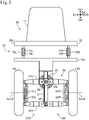
- Figs. 1(A)-1(C) and Fig. 2 show explanatory diagrams which illustrate a vehicle 10 as one embodiment.
- Fig. 1(A) shows a right side view of the vehicle 10
- Fig. 1(B) shows a top view of the vehicle 10
- Fig. 1(C) shows a bottom view of the vehicle 10
- Fig. 2 shows a rear view of the vehicle 10.
- the vehicle 10 is shown that is located on a horizontal ground GL ( Fig. 1(A) ), and thus does not lean.
- six directions DF, DB, DU, DD, DR, and DL are shown.
- a front direction DF is a front direction (i.e direction of forward movement) of the vehicle 10, and a back direction DB is opposite to the front direction DF.
- An upward direction DU is a vertically upward direction
- a downward direction DD is a vertically downward direction (i.e. a direction opposite to the upward direction DU).
- the vertically downward direction is the direction of gravity.
- the right direction DR is a right direction viewed from the vehicle 10 traveling in the front direction DF
- the left direction DL is opposite to the right direction DR. All the directions DF, DB, DR, and DL are horizontal directions.
- the right and left directions DR and DL are perpendicular to the front direction DF.
- the vehicle 10 is a small single-seater vehicle.
- the vehicle 10 ( Figs. 1(A) and 1(B) ) is a tricycle which has a vehicle body 90, a front wheel 12F, a left rear wheel 12L, and a right rear wheel 12R.
- the front wheel 12F is an example turn wheel, and is located at the center of the vehicle 10 in its width direction.
- the turn wheel is a wheel that can turn in the width direction of the vehicle 10 (i.e. to right direction and to left direction).
- the traveling direction of the turn wheel can turn to right and left relative to the front direction DF.
- the front wheel 12F is turnably supported on the vehicle body 90.
- the rear wheels 12R, 12L are drive wheels.
- the rear wheels 12R, 12L are spaced apart from each other symmetrically with regard to the center of the vehicle 10 in its width direction.
- the vehicle body 90 ( Fig. 1(A) ) has a main body 20.
- the main body 20 has a bottom portion 20b, a front wall portion 20a coupled to the bottom portion 20b on the front direction DF side, a rear wall portion 20c coupled to the bottom portion 20b on the back direction DB side, and a support portion 20d which extends from the top of the rear wall portion 20c toward the back direction DB.
- the main body 20 has a metal frame, and panels attached to the frame.
- the vehicle body 90 further has a seat 11 attached on the bottom portion 20b, an accelerator pedal 45 and a brake pedal 46 located on the front direction DF side of the seat 11, a controller 100 and a battery 120 attached on the bottom portion 20b, a front wheel support device 41 attached to the end on the upward direction DU side of the front wall portion 20a, and a steering wheel 41a attached to the front wheel support device 41.
- Other members e.g. roof, headlight, etc.
- the vehicle body 90 includes the members attached to the main body 20.
- the front wheel support device 41 ( Fig. 1(A) ) is a device that supports the front wheel 12F turnably about a turning axis Ax1.
- the front wheel support device 41 has a front fork 17, a bearing 68, and a steering motor 65.
- the front fork 17, which rotatably supports the front wheel 12F, is a telescopic fork having a coil spring and a shock absorber, for example.
- the bearing 68 couples the front fork 17 to the front wall portion 20a of the main body 20.
- the bearing 68 supports the front fork 17 (and thus the front wheel 12F) turnably about the turning axis Ax1 to right and left relative to the vehicle body 90.
- a turnable range of the front fork 17 may be a predetermined angular range (e.g. a range of less than 180 degrees). For example, the angular range may be limited by the front fork 17 coming into contact with another portion of the vehicle body 90.
- the steering motor 65 is an electric motor, and is coupled to the front wall portion 20a of the main body 20 and to the front fork 17.
- the steering motor 65 generates a torque which causes the front fork 17 (and thus the front wheel 12F) to turn in the width direction (i.e. to right direction and to left direction).
- the steering motor 65 is configured to apply a turning torque, which is a torque for controlling the turn of the front wheel 12F in the width direction, on the front wheel 12F (hereinafter sometimes referred to as turning actuator 65).
- the steering wheel is a member which can rotate to right and left directions.
- a rotational angle (sometimes referred to as input angle) of the steering wheel 41a relative to a predetermined rotational position (referred to as forward movement-rotational position) corresponding to forward traveling is example turn input information indicating turning direction and degree of turn.
- "input angle > 0" indicates a right turn
- "input angle ⁇ 0" indicates a left turn.
- the magnitude (i.e. absolute value) of input angle indicates the degree of turn.
- the driver can input turn input information by handling the steering wheel 41a.
- an elastic body e.g. spring such as coil spring and flat spring, resin such as rubber and silicon
- resin such as rubber and silicon
- a wheel angle Aw ( Fig. 1(B) ) is an angle indicating the direction of the front wheel 12F relative to the vehicle body 90.
- the wheel angle Aw is an angle of traveling direction D12 of the front wheel 12F relative to the front direction DF.
- the wheel angle Aw represents an angle about an axis parallel to the upward direction of the vehicle body 90 (which is the same as a vertically upward direction DU when the vehicle body 90 does not lean relative to the vertically upward direction DU).
- the traveling direction D12 is perpendicular to the rotational axis Axwl of the front wheel 12F.
- the wheel angle Aw represents an angle at which the front wheel 12F turns. If the front wheel 12F is steered, the wheel angle Aw corresponds to a so-called steering angle.
- the steering motor 65 is controlled by the controller 100 ( Fig. 1(A) ). When the turning torque generated by the steering motor 65 is smaller, the direction D12 of the front wheel 12F is allowed to turn to left or right independently of the input angle. The control of steering motor 65 will be discussed in detail later.
- An angle CA in Fig. 1(A) is a so-called caster angle.
- the caster angle CA is an angle between the upward direction of the vehicle body 90 (which is the same as a vertically upward direction DU when the vehicle body 90 does not lean relative to the vertically upward direction DU) and a direction along the turning axis Ax1 toward the vertically upward direction DU side.
- the caster angle CA is larger than zero. Accordingly, the direction along the turning axis Ax1 toward the vertically upward direction DU side is tilted diagonally backward.
- the intersection point P2 between the turning axis Ax1 of the front wheel support device 41 and the ground GL is located on the front direction DF side of the contact center P1 of the front wheel 12F with the ground GL.
- the distance Lt in the back direction DB between these points PI, P2 is referred to as a trail.
- a positive trail Lt indicates that the contact center P1 is located on the back direction DB side of the intersection point P2.
- the contact center P1 represents a gravity center of contact area Ca1 between the front wheel 12F and the ground GL.
- the gravity center of the contact area is a position of gravity center on the assumption that its mass is distributed evenly across the contact area.
- a contact center PbR of contact area CaR between the right rear wheel 12R and the ground GL, and a contact center PbL of contact area CaL between the left rear wheel 12L and the ground GL are identified in a similar manner.
- the two rear wheels 12R, 12L are rotatably supported on a rear wheel support 80.
- the rear wheel support 80 has a link mechanism 30, a lean motor 25 mounted on the top of the link mechanism 30, a first support portion 82 attached onto the top of the link mechanism 30, and a second support portion 83 attached to the front of the link mechanism 30 ( Fig. 1(A) ).
- Fig. 1(A) portions of the rear wheel support 80 which are hidden by the right rear wheel 12R are also depicted in solid lines.
- the rear wheel support 80, rear wheels 12R, 12L, and connector rod 75 (described later) which are hidden by the main body 20 are depicted in solid lines.
- the link mechanism 30 is depicted simply.
- the first support portion 82 ( Fig. 2 ) includes a plate-like section which extends parallel to the right direction DR on the upward direction DU side of the rear wheels 12R, 12L.
- the second support portion 83 ( Fig. 1(A), Fig. 1(B) ) is located on the front direction DF side of the link mechanism 30 between the left rear wheel 12L and the right rear wheel 12R.
- the right rear wheel 12R ( Fig. 1(B) , Fig. 2 ) is connected to a right drive motor 51R.
- the right drive motor 51R is an electric motor, and is secured to a right section of the rear wheel support 80.
- a rotational axis Axw2 ( Fig. 2 ) of the right drive motor 51R is the same as that of the right rear wheel 12R.
- the configurations of the left rear wheel 12L and the left drive motor 51L are similar to those of the right rear wheel 12R and the right drive motor 51R, respectively.
- These drive motors 51L, 51R are in-wheel motors which directly drive the rear wheels 12R, 12L.
- the left drive motor 51L and the right drive motor 51R may be collectively referred to as drive system 51S.
- Fig. 1(A)-Fig. 1(C) show a state where the vehicle body 90 does not lean but stands upright on the horizontal ground GL (that is, a state where a roll angle Ar described later is equal to zero).
- this state is referred to as upright state.
- a rotational axis Axw3 ( Fig. 2 ) of the left rear wheel 12L and the rotational axis Axw2 of the right rear wheel 12R are located on the same line, and are parallel to the right direction DR.
- the link mechanism 30 ( Fig. 2 ) is a so-called parallel linkage.
- the link mechanism 30 has three longitudinal link members 33L, 21, 33R arranged in order toward the right direction DR, and two lateral link members 31U, 31D arranged in order toward the downward direction DD.
- the longitudinal link members 33L, 21, 33R are parallel to the vertical direction
- the lateral link members 31U, 31D are parallel to the horizontal direction.
- the two longitudinal link members 33L, 33R, and the two lateral link members 31U, 31D form a parallelogram link mechanism.
- the center longitudinal link member 21 couples the centers of the lateral link members 31U, 31D.
- link members 33L, 33R, 31U, 31D, 21 are mutually coupled rotatably. In this embodiment, their rotational axes are parallel to the front direction DF.
- the link members coupled with each other may relatively rotate about the rotational axis within a predetermined angular range (e.g. a range of less than 180 degrees).
- the left drive motor 51L is attached to the left longitudinal link member 33L.
- the right drive motor 51R is attached to the right longitudinal link member 33R.
- the first support portion 82 and second support portion 83 ( Fig. 1(A) ) are secured.
- the link members 33L, 21, 33R, 31U, 31D, and the support portions 82, 83 are made of metal, for example.
- the link mechanism 30 has bearings for rotatably coupling link members.
- a bearing 38 rotatably couples the lower lateral link member 31D to the center longitudinal link member 21, and a bearing 39 rotatably couples the upper lateral link member 31U to the center longitudinal link member 21.
- a plurality of other link members are also coupled by bearings although they are not specifically described here.
- the lean motor 25 which is an example lean actuator configured to actuate the link mechanism 30, is an electric motor in this embodiment.
- the lean motor 25 is coupled to the center longitudinal link member 21 and to the upper lateral link member 31U.
- the rotational axis of the lean motor 25 is the same as that of the bearing 39, and is located at the center of the vehicle 10 in its width direction.
- the lean motor 25 rotates the upper lateral link member 31U relative to the center longitudinal link member 21. This causes the vehicle 10 to lean in its width direction (i.e. to right direction or to left direction).
- Such a leaning motion is also referred to as roll motion.
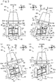
- Fig. 3(A), Fig. 3(B) show schematic diagrams of the states of the vehicle 10 on the horizontal ground GL. These figures show simplified rear views of the vehicle 10.
- Fig. 3(A) shows the state in which the vehicle 10 stands upright while
- Fig. 3(B) shows the state in which the vehicle 10 leans.
- the upper lateral link member 31U is perpendicular to the center longitudinal link member 21, all of the wheels 12F, 12R, 12L stand upright relative to the horizontal ground GL.
- the whole vehicle 10 including the vehicle body 90 stands upright relative to the ground GL.
- a vehicle body upward direction DVU in the figure represents the upward direction of the vehicle body 90. With the vehicle 10 not leaning, the vehicle body upward direction DVU is the same as the upward direction DU.
- an upward direction predetermined for the vehicle body 90 is used as the vehicle body upward direction DVU
- the center longitudinal link member 21 rotates clockwise relative to the upper lateral link member 31U, and thereby the right rear wheel 12R moves toward the vehicle body upward direction DVU side while the left rear wheel 12L moves toward the opposite side, relative to the vehicle body 90.
- these wheels 12F, 12R, 12L lean to the right direction DR side relative to the ground GL while all of the wheels 12F, 12R, 12L have contact with the ground GL.
- the whole vehicle 10 including the vehicle body 90 leans to the right direction DR side relative to the ground GL.
- the center longitudinal link member 21 rotates counterclockwise relative to the upper lateral link member 31U, and thereby the vehicle 10 leans to the left direction DL side although this is not illustrated.
- the link mechanism 30 can change the relative position between the left rear wheel 12L and the right rear wheel 12R in the vehicle body upward direction DVU. As a result, the vehicle body 90 leans relative to the ground GL.
- the lateral link members 31U, 31D are rotatably supported on the vehicle body 90 (via the center longitudinal link member 21, the first support portion 82, and a suspension system 70 described later). And, the rear wheels 12R, 12L are connected to the vehicle body 90 via a plurality of members including the lateral link members 31U, 31D. Accordingly, the distances between the rear wheels 12R, 12L and the vehicle body 90 in the vehicle body upward direction DVU are changed by rotating the lateral link members 31U, 31D relative to the vehicle body 90.
- the rotational axes (bearings 39, 38) of the lateral link members 31U, 31D are located between the right rear wheel 12R and the left rear wheel 12L. Accordingly, when the lateral link members 31U, 31D rotate, the direction of movement of the right rear wheel 12R is opposite to that of the left rear wheel 12L.
- the vehicle body upward direction DVU is tilted in the right direction DR side relative to the upward direction DU.
- the angle between the upward direction DU and the vehicle body upward direction DVU is referred to as roll angle Ar or lean angle Ar.
- roll angle Ar indicates a lean to the right direction DR side while “Ar ⁇ 0” indicates a lean to the left direction DL side.
- the roll angle Ar of the vehicle body 90 can be considered as the roll angle Ar of the vehicle 10.
- a control angle Ac of the link mechanism 30 is also shown in Fig. 3(B) .
- the control angle Ac represents an angle between the orientations of the upper lateral link member 31U and center longitudinal link member 21.
- "Ac>0” indicates that the center longitudinal link member 21 is tilted clockwise relative to the upper lateral link member 31U, as shown in the rear view of Fig. 3(B) .
- "Ac ⁇ 0" indicates that the center longitudinal link member 21 is tilted counterclockwise relative to the upper lateral link member 31U although this state is not illustrated.
- the control angle Ac is approximately the same as the roll angle Ar when the vehicle 10 is located on the horizontal ground GL (i.e. the ground GL perpendicular to the vertically upward direction DU).
- an axis AxL on the ground GL is a lean axis AxL.
- the link mechanism 30 and the lean motor 25 can cause the vehicle 10 to lean to right and left about the lean axis AxL.
- the lean axis AxL may be referred to as roll axis.
- the roll axis AxL is a straight line which passes through a contact center P1 between the front wheel 12F and the ground GL, and which is parallel to the front direction DF.
- the link mechanism 30 is an example lean device configured to lean the vehicle body 90 in the width direction of the vehicle 10 (sometimes referred to as lean device 30).
- Fig. 3(C), Fig. 3(D) show simplified rear views of the vehicle 10 similarly to Fig. 3(A), Fig. 3(B) .
- the ground GLx is inclined relative to the vertically upward direction DU (higher on the right side, and lower on the left side).
- Fig. 3(C) shows a state where the control angle Ac is equal to zero. In this state, all of the wheels 12F, 12R, 12L stand upright relative to the ground GLx.
- the vehicle body upward direction DVU is perpendicular to the ground GLx, and is tilted in the left direction DL side relative to the vertically upward direction DU.
- Fig. 3(D) shows a state where the roll angle Ar is equal to zero.
- the upper lateral link member 31U is approximately parallel to the ground GLx, and is tilted counterclockwise relative to the center longitudinal link member 21.
- the wheels 12F, 12R, 12L are tilted relative to the ground GL.
- the roll angle Ar of the vehicle body 90 can differ from the control angle Ac of the link mechanism 30 when the ground GLx is inclined.
- the rear wheel support 80 has a lock mechanism (not shown) for locking the link mechanism 30.
- the control angle Ac is fixed by actuating the lock mechanism. For example, the control angle Ac is fixed to zero when the vehicle 10 is parked.
- the main body 20 is coupled to the rear wheel support 80 via the suspension system 70 and the connector rod 75, as shown in Fig. 1(B) , Fig. 2 .
- the suspension system 70 has a left suspension 70L and a right suspension 70R.
- the suspensions 70L, 70R each are coupled to the support portion 20D of the main body 20 and to the first support portion 82 of the rear wheel support 80.
- the suspensions 70L, 70R have coil springs 71L, 71R and shock absorbers 72L, 72R, respectively, and are telescopic.
- the suspension system 70 allows relative movement between the rear wheel support 80 and the main body 20.
- the connector rod 75 is a rod which extends in the front direction DF as shown in Fig. 1(A), Fig. 1(B) .
- the connector rod 75 is located at the center of the vehicle 10 in its width direction.
- the end of the connector rod 75 on the front direction DF side is rotatably coupled to the rear wall portion 20c of the main body 20 (e.g. via a ball-and-socket joint).
- the end of the connector rod 75 on the back direction DB side is rotatably coupled to the second support portion 83 of the rear wheel support 80 (e.g. via a ball-and-socket j oint).
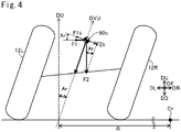
- Fig. 4 shows an explanatory diagram illustrating a balance of forces during turning.
- This figure shows a rear view of the rear wheels 12R, 12L when the turning direction is the right direction.
- the controller 100 may control the steering motor 65 and the lean motor 25 so that the rear wheels 12R, 12L (and thus the vehicle body 90) lean to the right direction DR relative to the ground GL.
- a gravity center 90c is shown in Fig. 4 .
- the gravity center 90c is a gravity center of the vehicle body 90.
- the gravity center 90c of the vehicle body 90 is a gravity center when the vehicle body 90 carries an occupant (and possibly a load).
- a first force F1 in the figure is a centrifugal force acting on the vehicle body 90.
- a second force F2 is a gravity acting on the vehicle body 90.
- the force acting on the vehicle body 90 acts on the gravity center 90c of the vehicle body 90.
- the mass of the vehicle body 90 is M (kg)
- the acceleration of gravity is g (about 9.8m/s 2 )
- the roll angle of the vehicle 10 relative to the vertical direction is Ar (degrees)
- the velocity of the vehicle 10 (i.e. vehicle velocity) during turning is V (m/s)
- the turning radius is R (m).
- ⁇ represents a multiplication sign (the same applies below).
- a force F1b in the figure is a component of the first force F1 in a direction perpendicular to the vehicle body upward direction DVU.
- a force F2b is a component of the second force F2 in a direction perpendicular to the vehicle body upward direction DVU.
- the force F1b and the force F2b are expressed in Equations 3 and 4, respectively:
- F 1 b F 1 * cos Ar
- F 2 b F 2 * sin Ar
- cos() is a cosine function
- sin() is a sine function (the same applies below).
- the force F1b is a component which causes the vehicle body upward direction DVU to be rotated to the left direction DL side while the force F2b is a component which causes the vehicle body upward direction DVU to be rotated to the right direction DR side.
- tan() is a tangent function (the same applies below).
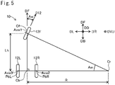
- Fig. 5 is an explanatory diagram showing a simplified relationship between the wheel angle Aw and the turning radius R.
- This figure shows the wheels 12F, 12R, 12L viewed in the downward direction DD.
- the roll angle Ar is equal to zero (i.e.
- the vehicle body upward direction DVU is parallel to the downward direction DD).
- the traveling direction D12 of the front wheel 12F turns to the right direction DR, and thus the vehicle 10 turns to the right direction DR.
- a front center Cf in the figure is the contact center P1 ( Fig. 1(C) ) of the front wheel 12F.
- the front center Cf is located on a line including the rotational axis Axwl of the front wheel 12F when the vehicle 10 is viewed in the downward direction DD.
- a rear center Cb is a center between the contact centers PbR, PbL ( Fig. 1(C) ) of the two rear wheels 12R, 12L.
- the rear center Cb is located at the middle between the rear wheels 12R, 12L on a line including the rotational axes Axw2, Axw3 of the rear wheels 12R, 12L when the vehicle 10 standing upright is viewed in the downward direction DD.
- a center Cr located on the right direction DR side of the vehicle 10 is a turning center. The turning motion of the vehicle 10 includes revolution of the vehicle 10 and rotation of the vehicle 10.
- the center Cr is a center of revolution (sometimes referred to as revolution center Cr).
- the front wheel 12F is a turn wheel instead of the rear wheels 12R, 12L in this embodiment.
- the rotation center is approximately the same as the rear center Cb.
- a wheelbase Lh is the distance between the front center Cf and the rear center Cb in the front direction DF.
- the wheelbase Lh is the same as the distance between the rotational axis Axwl of the front wheel 12F and the rotational axes Axw2, Axw3 of the rear wheels 12R, 12L in the front direction DF.
- arctan() is an inverse function of tangent function (the same applies below).
- Equation 6, Equation 6a, and Equation 7 described above are true when the vehicle 10 is turning while the velocity V and the turning radius R remain unchanged.
- Equation 6, Equation 6a, and Equation 7 represent a static state where the force F1b ( Fig. 4 ) due to centrifugal force and the force F2b due to gravity are in equilibrium.
- Equation 7 can be used as a good approximate equation which represents the relationship between the wheel angle Aw and the turning radius R.
- the actual force which acts on the vehicle changes dynamically.
- the controller 100 controls the vehicle 10 taking a roll torque acting on the vehicle body 90 into account.
- the roll torque will be described below.
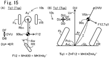
- Fig. 6(A)-Fig. 6(C) are explanatory diagrams of roll torque due to yaw angular acceleration of the vehicle 10.
- Fig. 6(A) are explanatory diagrams of the rear wheels 12R, 12L, and the gravity center 90c when viewed in the front direction DF.
- the vehicle 10 is located on a horizontal ground GL.
- Fig. 6(C) shows a state where the vehicle body 90 leans to the right direction DR (Ar>0).
- FIG. 6(B) is an explanatory diagram of the wheels 12F, 12R, 12L, and the gravity center 90c when viewed in a direction opposite to the vehicle body upward direction DVU
- the right direction DR and the left direction DL are shown for reference.
- these directions DR, DL are not perpendicular to the vehicle body upward direction DVU, but are tilted relative to the direction.
- a variable Z ( Fig. 6(A), Fig. 6(C) ) is a distance between the roll axis AxL and the gravity center 90c of the vehicle body 90.
- the roll axis AxL is located on the ground GL.
- the distance Z is the same as a distance in the vertically upward direction DU between the ground GL and the gravity center 90c in the upright state ( Fig. 6(A) ).
- a vertical axis Ux is an axis that passes through the projected point PcL and that is parallel to the vertically upward direction DU.
- a vehicle upward axis VUx is an axis that passes through the projected point PcL and that is parallel to the vehicle body upward direction DVU.
- the vehicle upward axis VUx passes through the projected point PcL and the gravity center 90c.
- an angle between the vehicle upward axis VUx and the vertical axis Ux is the roll angle Ar.
- a rotation center Rc is shown.
- the front wheel 12F is a turn wheel instead of the rear wheels 12R, 12L.
- the direction of the moving vehicle 10 e.g. the front direction DF
- the rotation center Rc can be located on the center (specifically, the rear center Cb in Fig. 5 ) between the rear wheels 12R, 12L.
- the rotation center Rc can be displaced from the rear center Cb.
- the rotation center Rc is located in the proximity of the center between the rear wheels 12R, 12L.
- the gravity center 90c of the vehicle body 90 is located close to the central portion of the vehicle body 90 in the top view of Fig. 6(B) . Accordingly, the gravity center 90c of the vehicle body 90 is located away from the rotation center Rc toward the front direction DF side.
- a distance X in this figure represents a positional difference (distance) in the front direction DF between the gravity center 90c and the rotation center Rc.
- a variable Ay" ( Fig. 6(B) ) is a yaw angular acceleration of the vehicle 10 (the variable Ay represents a yaw angle).
- a single quotation mark ['] attached to a variable indicates a first derivative with regard to time.
- a double quotation mark ["] indicates a second derivative with regard to time.
- Ay" represents a second derivative of a yaw angle with regard to time (i.e. yaw angular acceleration).
- the yaw angular acceleration Ay" is a yaw angular acceleration about an axis parallel to the vehicle body upward direction DVU.
- the yaw angular acceleration Ay" represents an angular acceleration of rotation of the vehicle 10 about the rotation center Rc.
- an axis perpendicular to the ground is referred to as ground perpendicular axis.
- the yaw angular acceleration Ay" represents a component about the axis parallel to the vehicle body upward direction DVU in the yaw angular acceleration about the ground perpendicular axis.
- the gravity center 90c of the vehicle body 90 is located away from the rotation center Rc by the distance X toward the front direction DF side. Accordingly, the vehicle body 90 is subject to a component F12 of inertial force in a direction opposite to that of the yaw angular acceleration Ay" (referred to as inertial force component F12).
- the direction of this inertial force component F12 is perpendicular to the vehicle body upward direction DVU.
- the direction from the rotation center Rc to the gravity center 90c is approximately parallel to the front direction DF in the top view of Fig. 6(B) . Accordingly, the direction of the inertial force component F12 is approximately perpendicular to the front direction DF.
- the magnitude of the inertial force component F12 is represented by a product of the mass M and an acceleration A90 of the gravity center 90c due to the yaw angular acceleration Ay".
- the acceleration A90 is represented by a product of the distance X and the yaw angular acceleration Ay". Accordingly, the magnitude of the inertial force component F12 is calculated by a formula [M ⁇ X ⁇ Ay"].
- the direction of the yaw angular acceleration Ay i.e. the direction of change in the yaw angular velocity Ay', is clockwise. In this case, the direction of the inertial force component F12 faces the left direction DL side.
- the inertial force component 12 is shown.
- the inertial force component F12 causes the vehicle body 90 to roll.
- the direction of the roll torque Tq1 (referred to as yaw angular acceleration roll direction) is right direction or left direction, and is opposite to the direction of the yaw angular acceleration Ay". For example, when the direction of the yaw angular acceleration Ay" is the direction of right turn, the direction of the roll torque Tq1 is the left direction.
- the wheel angle Aw changes.
- the yaw angular velocity Ay' changes, and therefore the magnitude of the yaw angular acceleration Ay" is larger than zero.
- the roll torque Tq1 acts on the vehicle body 90. In this manner, due to the change in wheel angle Aw (the angular velocity Aw' of the wheel angle Aw), the roll torque is generated (hereinafter sometimes referred to as first type roll torque).
- the magnitude of the first type roll torque can be determined as follows. First, a relationship between the wheel angle Aw and the yaw angular acceleration Ay" will be described. As described with reference to Fig. 5 , the front center Cf, rear center Cb, and revolution center Cr form a right angled triangle. When the roll angle Ar is equal to zero, the vehicle body upward direction DVU is parallel to the vertically downward direction DD. Accordingly, the positions of the points Cf, Cb, Cr shown in Fig. 5 are the same as positions when the points Cf, Cb, Cr are viewed in a direction parallel to the vehicle body upward direction DVU The traveling direction D12 of the front wheel 12F is assumed to be mapped to the wheel angle Aw regardless of the roll angle Ar.
- Equation A1 the length of the side which connects the rotation center Cr and the rear center Cb is denoted as Rx.
- Equation A1 the length of the side which connects the rotation center Cr and the rear center Cb is denoted as Rx.
- Equation A1 the length of the side which connects the rotation center Cr and the rear center Cb is denoted as Rx.
- Equation A1 is true.
- 1 / Rx tan Aw / Lh
- V Rx * Ay ′ Equation A3 is transformed to Equation A4.
- Equation A6 V / Lh * 1 / cos 2 Aw * Aw ′
- the first type roll torque is a roll torque due to the yaw angular acceleration Ay" in Equation A6.
- the angular velocity Aw' of the wheel angle Aw can be used to apply the first type roll torque Tqa on the vehicle body 90.
- the direction of the first type roll torque Tqa (sometimes referred to as turn roll direction) is opposite to that of the angular velocity Aw' of the wheel angle Aw. For example, when the wheel angle Aw turns in the right direction DR (Aw'>0), the direction of the first type roll torque Tqa is the left direction.
- Equation A8 is derived from Equation A7.
- Aw ′ Tqa * Lh * cos 2 Aw / M * X * Z * V Equation A8 represents the magnitude of the angular velocity Aw' of the wheel angle Aw required to generate the first type roll torque Tqa.
- the steering motor 65 can change the wheel angle Aw and thus its angular velocity Aw' by generating the turning torque. As indicated in Equation A6, the angular velocity Aw' of the wheel angle Aw changes the yaw angular acceleration Ay" of the vehicle 10. In this manner, the turning torque is an example force which changes the yaw angular acceleration Ay".
- the steering motor 65 is an example force generator configured to generate a force which changes the yaw angular acceleration Ay" (sometimes referred to as force generator 65).
- Fig. 7 is a block diagram showing the configuration relating to control of the vehicle 10.
- the vehicle 10 has a vehicle velocity sensor 122, an input angle sensor 123, a wheel angle sensor 124, a direction sensor 126, an accelerator pedal sensor 145, a brake pedal sensor 146, a controller 100, a right drive motor 51R, a left drive motor 51L, a lean motor 25, and a steering motor 65.
- the vehicle velocity sensor 122 is a sensor for detecting a vehicle velocity of the vehicle 10.
- the vehicle velocity sensor 122 is attached on the lower end of the front fork 17 ( Fig. 1(A) ) to detect a rotational rate of the front wheel 12F.
- the rotational rate is correlated with the velocity (sometimes referred to as vehicle velocity) of the vehicle 10. Accordingly, the sensor 122 for detecting the rotational rate can be considered to detect the vehicle velocity.
- the input angle sensor 123 is a sensor for detecting an orientation of the steering wheel 41a (i.e. input angle).
- the input angle sensor 123 is attached to the steering wheel 41a ( Fig. 1(A) ).
- the input angle sensor 123 is an example turn input information acquisition device configured to acquire an input angle AI (an example turn input information).
- the wheel angle sensor 124 is a sensor for detecting a wheel angle of the front wheel 12F.
- the wheel angle sensor 124 is attached to the front wall portion 20a of the main body 20 ( Fig. 1(A) ).
- the wheel angle sensor 124 detects the wheel angle about the turning axis Ax1 (sometimes referred to as detected angle Awx).
- the turning axis Ax1 rolls with the vehicle body 90.
- a direction parallel to the turning axis Ax1 (sometimes referred to as direction of turning axis Ax1) can differ from the vehicle body upward direction DVU.
- the direction sensor 126 determines the roll angle Ar and the yaw angular velocity.
- the direction sensor 126 is secured to the vehicle body 90 ( Fig. 1(A) (specifically, to the rear wall portion 20c).
- the direction sensor 126 also includes an acceleration sensor 126a, a gyroscope sensor 126g, and a control unit 126c.
- the acceleration sensor is a sensor that detects acceleration in any direction, for example, triaxial acceleration sensor.
- a direction of acceleration detected by the acceleration sensor 126a will be referred to as detected direction. With the vehicle 10 stopped, the detected direction is the same as the vertically downward direction DD.
- the gyroscope sensor 126g is a sensor that detects angular velocity about a rotational axis in any direction, for example, triaxial angular velocity sensor.
- the control unit 126c uses a signal from the acceleration sensor 126a, a signal from the gyroscope sensor 126g, and a signal from vehicle velocity sensor 122 to determine the roll angle Ar and the yaw angular velocity.
- the control unit 126c is a data processor including a computer.
- the control unit 126c uses the velocity V detected by the vehicle velocity sensor 122 to calculate the acceleration of the vehicle 10. Then, the control unit 126c uses the acceleration to determine the deviation of the detected direction from the actual vertically downward direction DD due to the acceleration of the vehicle 10 (e.g. the deviation of the detected direction toward the front direction DF or back direction DB is determined). In addition, the control unit 126c uses the angular velocity detected by the gyroscope sensor 126g to determine the deviation of the detected direction from the actual vertically downward direction DD due to the angular velocity of the vehicle 10 (e.g. the deviation of the detected direction toward the right direction DR or left direction DL is determined).
- the control unit 126c uses the determined deviations to modify the detected direction, and thereby determines the vertically downward direction DD. In this manner, the direction sensor 126 can determine the vertically downward direction DD properly under a variety of driving conditions of the vehicle 10. The control unit 126c then determines the vertically upward direction DU opposite to the vertically downward direction DD, and calculates the roll angle Ar between the vertically upward direction DU and the predetermined vehicle body upward direction DVU In addition, the control unit 126c determines a component of angular velocity about the axis parallel to the vehicle body upward direction DVU from the angular velocity determined by the gyroscope sensor 126g to identify the determined angular velocity as the yaw angular velocity.
- the accelerator pedal sensor 145 is attached to the accelerator pedal 45 ( Fig. 1(A) ) in order to detect an accelerator operation amount.
- the brake pedal sensor 146 is attached to the brake pedal 46 ( Fig. 1(A) ) in order to detect a brake operation amount.
- Each sensor 122, 123, 124, 145, 146 is configured using a resolver or encoder, for example.
- the controller 100 has a main control unit 110, a drive device control unit 300, a lean motor control unit 400, and a steering motor control unit 500.
- the controller 100 operates with electric power from the battery 120 ( Fig. 1(A) ).
- the control units 110, 300, 400, 500 each has a computer. More specifically, the control units 110, 300, 400, 500 have processors 110p, 300p, 400p, 500p (e.g. CPU), volatile memories 110v, 300v, 400v, 500v (e.g. DRAM), and non-volatile memories 110n, 300n, 400n, 500n (e.g. flash memory), respectively.
- the non-volatile memories 110n, 300n, 400n, 500n store in advance programs 110g, 300g, 400g, 500g for operating the corresponding control units 110, 300, 400, 500, respectively.
- the non-volatile memory 110n of the main control unit 110 stores in advance map data MAr, MCw.
- the processors 110p, 300p, 400p, 500p perform a variety of processes by executing the corresponding programs 110g, 300g, 400g, 500g, respectively.
- the processor 110p of the main control unit 110 receives signals from the sensors 122, 123, 124, 126, 145, 146. The processor 110p then uses the received signals to output instructions to the drive device control unit 300, the lean motor control unit 400, and the steering motor control unit 500.
- the processor 300p of the drive device control unit 300 controls the drive motors 51L, 51R according to the instruction from the main control unit 110.
- the processor 400p of the lean motor control unit 400 controls the lean motor 25 according to the instruction from the main control unit 110.
- the processor 500p of the steering motor control unit 500 controls the steering motor 65 according to the instruction from the main control unit 110.
- These control units 300, 400, 500 respectively have electric power control modules 300c, 400c, 500c which supply the motors 51L, 51R, 25, 65 under control with electric power from the battery 120.
- the electric power control modules 300c, 400c, 500c are configured using an electric circuit (e.g. inverter circuit). It should be noted that a portion of the main control unit 110 which performs processing for controlling the steering motor 65, and the steering motor control unit 500 as a whole is an example force controller configured to control the force generator 65 (sometimes referred to as force controller 910).
- Fig. 8 is a flowchart showing an example control process of the steering motor 65.
- the steering motor 65 is controlled so that a change in the wheel angle Aw results in a roll torque which makes the roll angle Ar close to a target roll angle.
- each step is labeled with a reference of an alphabet "S" followed by a numeral.
- Fig. 8 illustrates the process when the vehicle 10 is moving forward. As described later, a variety of parameters are used in the control process. It should be noted that the mass M of the vehicle body 90, the acceleration of gravity g, the distance X, the distance Z, and the wheelbase Lh can each be measured experimentally.
- predetermined values (sometimes referred to as reference values M,g, X, Z, Lh) are used as the respective parameters M,g, X, Z, Lh. It should be noted that the mass M of the vehicle body 90 corresponds to a so-called sprung mass.
- the processor 110p of the main control unit 110 acquires data from the sensors 122, 123, 124, 126, 145, 146.
- the processor 110p determines current information, in particular, the velocity V, input angle AI, wheel angle Aw, roll angle Ar, yaw angular velocity Ay', accelerator operation amount Pa, brake operation amount Pb.
- the processor 1 10p uses the input angle AI to determine a target roll angle Art.
- a correspondence relationship between the input angle AI and the target roll angle Art is predetermined by map data MAr ( Fig. 7 ).
- the processor 110p references the map data MAr to identify the target roll angle Art.
- the direction (right or left) of the target roll angle Art is the same as the turning direction determined by the input angle AI.
- the processor 110p calculates a roll angle difference dAr by subtracting the current roll angle Ar from the target roll angle Art.
- the processor 110p determines a control parameter.
- the processor 1 1Op determines a P gain Gp1 for proportional control (sometimes referred to as first gain Gp1). It should be noted that the processor 110p performs S220-S230 and S240 in parallel.
- the intermediate control value Ctq indicates a reference roll torque.
- the zero intermediate control value Ctq indicates a roll torque of zero.
- the positive intermediate control value Ctq indicates a roll torque in the right direction DR.
- the negative intermediate control value Ctq indicates a roll torque in the left direction DL.
- the steering motor 65 is controlled so that the first type roll torque generated due to the angular velocity Aw' of the wheel angle Aw is made close to the reference roll torque.
- the larger the magnitude of the roll angle difference dAr is, the larger the magnitude of the intermediate control value Ctq (i.e. the reference roll torque) is.
- the larger the first gain Gp1 is, the larger the magnitude of the reference roll torque is.
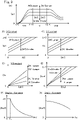
- Fig. 9(A)-Fig. 9(C) are graphs showing examples of the first gain Gp1.
- the horizontal axis represents the velocity V
- the vertical axis represents the first gain Gp1.
- the velocity V is within a first range VR1 between zero and a first threshold VI, inclusive
- the steering motor 65 is controlled so that the angular velocity Aw' of the wheel angle Aw is made close to the value calculated according to Equation A8 described above.
- the absolute value of the angular velocity Aw' of the wheel angle Aw is inversely proportional to the velocity V. If the angular velocity Aw' strictly follows Equation A8, the absolute value of the angular velocity Aw' diverges as the velocity V approaches zero.
- the first gain Gp1 is smaller when the velocity V is smaller. This results in the smaller intermediate control value Ctq (i.e. reference roll torque), and therefore the divergence of the angular velocity Aw' is suppressed.
- the velocity V is within a second range VR2 of not smaller than a second threshold V2
- the second threshold V2 is a value within a range between 30km/hour and 40km/hour, inclusive.
- the front wheel 12F rotating about the rotational axis Axwl also leans to the right direction DR along with the vehicle body 90.
- the front wheel 12F is subject to a torque about an axis perpendicular to the rotational axis Axwl and parallel to the front direction DF.
- the front wheel 12F ( Fig. 1(B) ) is subject to a torque that turns the traveling direction D12 about the turning axis Ax1 to the right direction DR.
- the front wheel 12F turns to the right direction DR.
- the torque which turns the front wheel 12F increases with an increase in the angular momentum of the front wheel 12F, i.e. an increase in the velocity V.
- the front wheel 12F can spontaneously turn to the lean direction of the vehicle body 90.
- the first gain Gp1 is smaller in order to allow for the spontaneous turn of the front wheel 12F.
- the magnitude of the intermediate control value Ctq i.e. reference roll torque
- the magnitude of the turning torque of the steering motor 65 is also smaller.
- Fig. 9(B) is a graph when the velocity V is constant, where the horizontal axis represents the absolute value of the angular velocity AI' of the input angle AI, and the vertical axis represents the first gain Gp1. As shown, the larger the absolute value of the angular velocity AI' is, the larger the first gain Gp1 is.
- Fig. 9(C) is a graph when the velocity V is constant, where the horizontal axis represents the absolute value of the angular acceleration AI" of the input angle AI, and the vertical axis represents the first gain Gp1.
- the reason is as follows.
- the driver turns the steering wheel 41a quickly in order to change quickly the traveling direction of the vehicle 10.
- the roll angle Ar is required to change quickly when the absolute value of the angular velocity AI' is larger or when the absolute value of the angular acceleration AI" is larger. Therefore, in this embodiment, in order to make the absolute value of the intermediate control value Ctq (i.e. reference roll torque) larger, the larger the absolute value of the angular velocity AI' is, the larger the first gain Gp1 is, and the larger the absolute value of the angular acceleration AI" is, the larger the first gain Gp1 is.
- the processor 110p sets a second upper limit Lm2 to the first gain Gp1.
- the correspondence between the first gain Gp1 and the other parameters may be any of a variety of other correspondences instead of the correspondences shown in Fig. 9(A)-Fig. 9(C) .
- the first gain Gp1 may remain without any reduction, or may increase.
- the range of the velocity V of not smaller than the first threshold V1 may be divided into three ranges of low velocity range, medium velocity range, and high velocity range.
- the first gain Gp1 of the low velocity range and the first gain Gp1 of the high velocity range may be set to a larger value as compared to the first gain Gp1 of the medium velocity range.
- the larger first gain Gp1 of the low velocity range can assist in the front wheel 12F turning to the turning direction when the gyroscopic moment is smaller.
- the rotational rate of the front wheel 12F is larger, and thus the angular momentum of the front wheel 12F is also larger. In this case, a larger torque may be required to turn the front wheel 12F to the turning direction.
- the larger first gain Gp1 of the high velocity range can assist in the front wheel 12F turning to the turning direction.
- Fig. 9(D) is a graph showing an example relationship between the roll angle difference dAr and the intermediate control value Ctq.
- the horizontal axis represents the absolute value of the roll angle difference dAr
- the vertical axis represents the absolute value of the intermediate control value Ctq.
- This graph shows the case where the velocity V is constant.
- the absolute of the roll angle difference dAr is constant, the larger the absolute value of the angular velocity AI' of the input angle AI is, the larger the absolute value of the intermediate control value Ctq is.
- the larger the absolute value of the angular acceleration AI" of the input angle AI is, the larger the absolute value of the intermediate control value Ctq is.
- the processor 110p uses the intermediate control value Ctq to determine the angular velocity of the wheel angle Aw (sometimes referred to as additional angular velocity Awd')
- the additional angular velocity Awd' represents an angular velocity such that the additional angular velocity Awd' is added to the current angular velocity Aw' of the wheel angle Aw to generate the reference roll torque mapped to the intermediate control value Ctq.
- Equation A8 describe above.
- Equation A8 the intermediate control value Ctq is used instead of the first type roll torque Tqa, and the angular velocity Aw' represents the additional angular velocity Awd'.
- the processor 110p uses the reference values Lh, M, X, Z, the intermediate control value Ctq, the wheel angle Aw, and the velocity V to calculate the additional angular velocity Awd'.
- Fig. 9(E)-Fig. 9(G) are graphs showing examples of the additional angular velocity Awd'.
- the horizontal axis represents the absolute value of the intermediate control value Ctq
- the vertical axis represents the absolute value of the additional angular velocity Awd'.
- the processor 110p sets a first upper limit Lm1 to the absolute value of Awd'.
- the horizontal axis represents the velocity V
- the vertical axis represents the absolute value of the additional angular velocity Awd'.
- the absolute value of Awd' is inversely proportional to V, as also indicated in Equation A8 described above.
- the absolute value of Awd' is limited to the first upper limit Lm1.
- the horizontal axis represents the absolute value of the wheel angle Aw
- the vertical axis represents the absolute value of the additional angular velocity Awd'.
- the processor 110p uses the additional angular velocity Awd' to determine an actuation control value Cw (sometimes simply referred to as control value Cw).
- the control value Cw indicates a turning torque to be generated by the steering motor 65.
- the control value Cw indicates direction and magnitude of electric current to be supplied to the steering motor 65.
- the absolute value of the control value Cw indicates the magnitude of the electric current (i.e. the magnitude of the turning torque).
- the positive/negative signs of the control value Cw indicates the direction of the electric current (i.e. the direction of the turning torque) (e.g. the positive sign indicates the right direction while the negative sign indicates the left direction).
- a correspondence relationship between the additional angular velocity Awd' and the control value Cw is predetermined by map data MCw ( Fig. 7 ).
- the positive/negative sign of the control value Cw i.e. the direction of the turning torque
- the processor 110p references the map data MCw to identify the actuation control value Cw mapped to the additional angular velocity Awd'.
- the processor 110p provides data indicative of the actuation control value Cw to the steering motor control unit 500.
- the processor 500p of the steering motor control unit 500 controls the electric power to be supplied to the steering motor 65 according to the actuation control value Cw.
- the processor 500p provides the data indicative of the actuation control value Cw to the electric power control module 500c.
- the electric power control module 500c controls the electric power to be supplied to the steering motor 65 according to the actuation control value Cw.
- the steering motor 65 outputs the turning torque according to the supplied electric power.
- the process of Fig. 8 ends.
- the controller 100 repeatedly performs the process of Fig. 8 . As such, the controller 100 continuously controls the steering motor 65 to output the turning torque appropriate for the state of the vehicle 10.
- the actuation control value Cw indicates the turning torque mapped to the additional angular velocity Awd' (S270).
- a parameter Tqa mapped to the additional angular velocity Awd' according to Equation A8 indicates the first type roll torque Tqa to be generated due to the additional angular velocity Awd'.
- the intermediate control value Ctq is used as the parameter Tqa indicative of the first type roll torque to calculate the additional angular velocity Awd' according to Equation A8. Therefore, the intermediate control value Ctq indicates the first type roll torque.
- the intermediate control value Ctq is determined through the proportional control using the roll angle difference dAr and the control parameter (in this case, P gain Gp1).
- the magnitude of the intermediate control value Ctq (i.e. the magnitude of the first type roll torque) is increased with an increase in the magnitude of the roll angle difference dAr.
- the positive/negative sign of the intermediate control value Ctq (i.e. the direction of the first type roll torque) is the same as the positive/negative sign of the roll angle difference dAr (i.e. roll direction from the roll angle Ar to the target roll angle Art) (hereinafter, the roll direction from the roll angle Ar to the target roll angle Art may be referred to as 'direction of roll angle difference dAr').
- the roll angle difference dAr indicates the reference roll torque which is a reference of the first type roll torque to be generated due to the additional angular velocity Awd'.
- the magnitude of the roll angle difference dAr indicates a reference magnitude which is the magnitude of the reference roll torque.
- the positive/negative sign of the roll angle difference dAr indicates a reference direction which is the direction of the reference roll torque.
- the roll angle difference dAr is an example of reference information which indicates the reference direction as a reference of direction and the reference magnitude as a reference of magnitude for the first type roll torque to act on the vehicle body 90 (hereinafter, the roll angle difference dAr may be referred to as reference information dAr).
- the controller 100 controls the steering motor 65 according to the actuation control value Cw to be determined using the reference information dAr. As such, the steering motor 65 generates the turning torque so that the direction of the first type roll torque is the same as the reference direction, and the magnitude of the first type roll torque increases with an increase in the reference magnitude. If the steering motor 65 is controlled according to the actuation control value Cw, the roll angle Ar approaches the target roll angle Art, and therefore the vehicle 10 can travel at the roll angle Ar appropriate for the input angle AI (i.e. with the target roll angle Art).
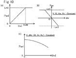
- Fig. 10(A)-Fig. 10(C) are graphs showing examples of the turning torque Tqw controlled in the process of Fig. 8 .
- the horizontal axis represents the absolute value of the actuation control value Cw
- the vertical axis represents the absolute value of the turning torque Tqw.
- the absolute value of the turning torque Tqw increases with an increase in the absolute value of the actuation control value Cw.
- the processor 110p modifies the absolute value of the actuation control value Cw to the upper limit CwM in S280 of Fig. 8 if the absolute value of the actuation control value Cw is equal to or larger than a predetermined upper limit CwM. Accordingly, the absolute value of the turning torque Tqw is limited to an upper limit Lm3 mapped to the upper limit CwM. As a result, the wheel angle Aw is suppressed from changing rapidly.
- the horizontal axis represents the roll angle difference dAr
- the vertical axis represents the turning torque Tqw.
- the velocity V, input angle AI, wheel angle Aw, and yaw angular velocity Ay' each are constant.
- An angular velocity of rotation of the turntable represents a yaw angular velocity about the axis parallel to the vertically upward direction DU.
- the yaw angular velocity Ay' about the axis parallel to the vehicle body upward direction DVU can be determined using data from the direction sensor 126.
- the magnitude of the yaw angular velocity Ay' increases with an increase in the angular velocity of rotation of the turntable.
- the turntable has a plurality of rollers which rotates the respective wheels 12F, 12R, 12L at the rotational rate according to the velocity V.
- the front fork 17 is fixed to the vehicle body 90.
- the turning torque Tqw can be determined using the electric current to be supplied to the steering motor 65.
- the absolute value of the intermediate control value Ctq to be determined in S250 increases with an increase in the absolute value of the roll angle difference dAr. Accordingly, the larger the absolute value of the roll angle difference dAr is, the larger the absolute value of the turning torque Tqw is also (however, the absolute value of the turning torque Tqw is limited to the upper limit Lm3).
- the roll angle difference dAr being a positive value indicates that a reference roll direction from the roll angle Ar to the target roll angle Art is rightward.
- the direction of the first type roll torque Tqa is the left direction DL.
- a negative turning torque Tqw is generated that turns the direction D12 of the front wheel 12F to the left direction DL.
- the roll angle difference dAr is a negative value, a positive turning torque Tqw is generated.
- Fig. 10(C) the horizontal axis represents the absolute value of the wheel angle Aw, and the vertical axis represents the absolute value of the turning torque Tqw.
- This graph illustrates characteristics under the condition (referred to as first condition) that each of the velocity V and the reference information dAr (i.e. the reference direction and reference magnitude) is maintained constant (the absolute value of dAr is larger than zero).
- the other parameters e.g. AI, Ar, Ay'
- the wheel angle Aw is variable. In order to realize such a condition, the vehicle 10 is placed on the above-mentioned turntable.
- the roller for supporting the front wheel 12F is configured to respond to any turn of the front wheel 12F to turn to the same direction.
- the roller for supporting the front wheel 12F turns along with the front wheel 12F to the direction of the turning torque.
- the controller 100 can make the first type roll torque due to the angular velocity Aw' close to the reference torque.
- the controller 100 performs the process of Fig. 8 to control the steering motor 65 so that the roll angle Ar approaches the target roll angle Art.
- the vehicle 10 can travel at the roll angle Ar appropriate for the input angle AI.
- the steering motor 65 turns the front wheel 12F to the left direction, which is opposite to the direction of the roll angle difference dAr.
- the roll angle Ar quickly approaches the target roll angle Art.
- the steering motor 65 then outputs the turning torque through the similar control so that the roll angle Ar is maintained at the roll angle difference dAr.
- the wheel angle Aw can approach an angle appropriate for the roll angle Ar ( Fig. 4 , Fig. 5 ).
- the magnitude of the roll angle difference dAr is smaller, the magnitude of the turning torque is also smaller.
- the front wheel 12F can spontaneously turn to the roll direction of the vehicle body 90. Accordingly, the vehicle 10 can make a turn appropriate for the input angle AI. For example, the vehicle 10 can make the turn as shown in Fig. 4 , Fig. 5 .
- the first type roll torque Tqa obtained using the angular velocity Aw' of the wheel angle Aw is generated using the inertial force F12 in the direction opposite to that of the yaw angular acceleration Ay". Accordingly, as compared to when the vehicle body 90 rolls due to the roll torque generated directly by the lean motor 25, the lateral acceleration which the driver feels is suppressed when vehicle body 90 rolls due to the first type roll torque Tqa.
- Fig. 11 is a flowchart showing an example control process of the lean motor 25.
- the lean motor 25 is controlled to generate a roll torque which makes the roll angle Ar close to a target roll angle.
- the processor 110p of the main control unit 110 acquires signals from the sensors 123, 126. The processor 110p then determines current information, in particular, the input angle AI, roll angle Ar.
- S520, S530 is the same as S220, S230 in Fig. 8 , respectively.
- the processor 110p uses the roll angle difference dAr to determine a control value CwL. In this embodiment, the processor 110p then determines the control value CwL through a proportional control using the roll angle difference dAr.
- the processor 110p provides data indicative of the control value CwL to the lean motor control unit 400.
- the processor 400p of the lean motor control unit 400 controls the electric power to be supplied to the lean motor 25 according to the control value CwL. Specifically, the processor 400p provides the data indicative of the control value CwL to the electric power control module 400c.
- the electric power control module 400c controls the electric power to be supplied to the lean motor 25 according to the control value CwL.
- the lean motor 25 outputs the roll torque according to the supplied electric power.
- the process of Fig. 11 ends.
- the controller 100 repeatedly performs the process of Fig. 11 .
- the controller 100 continuously controls the lean motor 25 to output the roll torque appropriate for the state of the vehicle 10.
- the controller 100 controls each of the lean motor 25 and the steering motor 65 to generate the roll torque which makes the roll angle Ar close to the target roll angle Art.
- the vehicle 10 can travel at the roll angle Ar appropriate for the input angle AI. Then, the vehicle 10 can make a turn appropriate for the input angle AI.
- the main control unit 110 Fig. 7
- the drive device control unit 300 serve as a drive controller 900 for controlling the drive motors 51R, 51L.
- the drive controller 900 controls the drive motors 51R, 51L to achieve an acceleration appropriate for the accelerator operation amount Pa and a deceleration appropriate for the brake operation amount Pb.
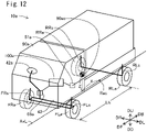
- Fig. 12 shows a perspective view of a vehicle in a second embodiment.
- the vehicle 10a is a four-wheel vehicle having two front wheels FRa, FLa and two rear wheels RRa, RLa.
- the two front wheels FRa, RLa are turn wheels, and can turn in the width direction of the vehicle 10a.
- the two rear wheels RRa, RLa are drive wheels.
- the vehicle 10a further has a vehicle body 90a, suspensions FRs, FLs, RRs, RLs, a steering device 42, a steering wheel 42a, a drive motor 51, and a controller 100a.
- the wheels FRa, FLa, RRa, RLa are coupled to the vehicle body 90a by the suspensions FRs, FLs, RRs, RLs, respectively.
- the suspensions FRs, FLs, RRs, RLs may be a variety of suspensions such as double wishbone suspension, torsion beam suspension.
- a drive motor 51a is connected to the rear wheels RRa, RLa.
- the rear wheels RRa, RLa are powered by the drive motor 51a to rotate.
- the steering device 42 is connected to the front wheels FRa, FLa.
- the steering device 42 may be configured in a variety of ways such as rack-and-pinion type.
- the steering wheel 42a is connected to the steering device 42.
- the driver can turn the traveling direction of the front wheels FRa, FLa to right or left by rotating the steering wheel 42a.
- the steering device 42 has a steering motor 65a.
- the steering motor 65a generates a torque which assists in steering.
- the controller 100a controls the steering motor 65a and the drive motor 51a.
- a distance Lh is a so-called wheelbase.
- the roll axis AxL is located on the ground GL at the center of the vehicle body 90a in its width direction. Because the front wheels FRa, FLa are turn wheels, and the rear wheels RRa, RLa are not turn wheels, a rotation center Rac is located in the proximity of the center between the rear wheels RRa, RLa.
- the gravity center 90ac of the vehicle body 90a is located on the front direction DF side of the rotation center Rac.
- a distance X is a distance in the front direction DF between the rotation center Rac and the gravity center 90ac of the vehicle body 90a.
- a distance is a distance between the roll axis AxL and the gravity center 90ac.
- the distance Z is the same as a height of the gravity center 90ac from the ground.
- the vehicle 10a has as a control related configuration a configuration obtained by modifying that of Fig. 7 as follows.
- Fig. 13 is a flowchart showing an example control process of the steering motor 65a.
- the controller 100a controls the steering motor 65 so that a change in the wheel angle Aw results in a roll torque which makes the angular acceleration Ar" (referred to as roll angular acceleration Ar") of the roll angle Ar smaller.
- predetermined values are used as the mass M of the vehicle body 90a, the acceleration of gravity g, the distance X, the distance Z, and the wheelbase Lh.
- the wheel angle Aw is an angle of direction of the front wheel (e.g. Right front wheel FRa or left front wheel FLa) relative to the front direction DF of the vehicle 10a.
- the processor 110p of the main control unit 110 acquires data from the sensors 122, 123, 124, 126, 145, 146.
- the processor 110p determines current information, in particular, the velocity V, input angle AI, wheel angle Aw, roll angle Ar, yaw angular velocity Ay', accelerator operation amount Pa, brake operation amount Pb.
- the processor 110p calculates the angular acceleration Ar" of the roll angle Ar. Initially, the processor 110p uses the roll angle Ar to calculate the angular velocity Ar'.
- the method of calculating the angular velocity Ar' may include a variety of methods. In this embodiment, the processor 110p calculates a difference between the current roll angle Ar and the roll angle Ar at a point of time in the past by a predetermined time difference from current time by subtracting the latter from the former. The processor 110p then employs as the angular velocity Ar' a value obtained by dividing the difference by the time difference. The processor 110p uses the angular velocity Ar' to calculate the angular acceleration Ar" in the same manner, which is a derivative value of the angular velocity Ar'.
- Equation B1 is a formula of the roll torque Tqr which acts on the vehicle body 90a when the roll angular acceleration is Ar" .
- Tqr I + M * Z 2 * Ar "
- the roll torque Tqr is approximated by two components [I ⁇ Ar"] and [M ⁇ Z 2 ⁇ Ar"].
- the variable I is an inertia moment of the vehicle body 90 when the rotational axis passes through the gravity center 90c (where the rotational axis is parallel to the roll axis AxL).
- [M ⁇ Z 2 ] is an additional term when the rotational axis away from the gravity center 90c by the distance Z.
- the coefficient [I+M ⁇ Z 2 ] is determined in advance by experimentally measuring a ratio of the roll torque Tqr to the roll angular acceleration Ar".
- the processor 110p uses Equation B1 described above to calculate the roll torque Tqr which acts on the vehicle body 90a when the roll angular acceleration of the vehicle body 90a is Ar''.
- the processor 110p then employs as the target roll torque Tqt a roll torque obtained by inverting the direction of the roll torque Tqr.
- Fig. 14(A) is a graph showing an example relationship between the roll angular acceleration Ar" and the target roll torque Tqt.
- the horizontal axis represents the roll angular acceleration Ar"
- the vertical axis represents the target roll torque Tqt.
- the direction (i.e. positive/negative sign) of the target roll torque Tqt is opposite to the direction (i.e. positive/negative sign) of the roll angular acceleration Ar".
- the processor 110p determines the angular velocity of the wheel angle Aw (referred to as additional angular velocity Awd') required to generate the target roll torque Tqt.
- the additional angular velocity Awd' is calculated by substituting the target roll torque Tqt for the first type roll torque Tqa in Equation A8 described above.
- Fig. 14(B)-Fig. 14(D ) are graphs showing examples of the additional angular velocity Awd'.
- the horizontal axis represents the absolute value of the target roll torque Tqt
- the vertical axis represents the absolute value of the additional angular velocity Awd'.
- the processor 110p sets a fourth upper limit Lm4 to the absolute value of Awd'.
- the horizontal axis represents the velocity V
- the vertical axis represents the absolute value of the additional angular velocity Awd'.
- the absolute value of Awd' is inversely proportional to V, as also indicated in Equation A8 described above.
- the absolute value of Awd' is limited to the fifth upper limit Lm5.
- the horizontal axis represents the absolute value of the wheel angle Aw
- the vertical axis represents the absolute value of the additional angular velocity Awd'.
- the processor 110p determines a control parameter.
- the processor 110p determines a P gain Gp2 for proportional control (sometimes referred to as second gain Gp2). It should be noted that the processor 110p performs S220a-S235a and S240a in parallel.
- the second gain Gp2 is determined to be a predetermined value. Instead, the second gain Gp2 may be a variable value that varies depending on another parameter.
- the processor 110p provides data indicative of the control value Cw2 to the steering motor control unit 500.
- the processor 500p of the steering motor control unit 500 controls the electric power to be supplied to the steering motor 65a according to the control value Cw2.
- the processor 500p provides the data indicative of the control value Cw2 to the electric power control module 500c.
- the electric power control module 500c controls the electric power to be supplied to the steering motor 65a according to the control value CW2.
- the steering motor 65a outputs the turning torque according to the supplied electric power.
- the process of Fig. 13 ends.
- the controller 100a repeatedly performs the process of Fig. 13 .
- the controller 100a continuously controls the steering motor 65a to output the turning torque which suppresses the roll angular acceleration Ar".
- the control value Cw2 indicates the turning torque mapped to the additional angular velocity Awd' (S270a).
- a parameter Tqa mapped to the additional angular velocity Awd' according to Equation A8 indicates the first type roll torque Tqa to be generated due to the additional angular velocity Awd'.
- the target roll torque Tqt is used as the parameter Tqa indicative of the first type roll torque to calculate the additional angular velocity Awd' according to Equation A8. Therefore, the target roll torque Tqt indicates the target torque of the first type roll torque.
- a roll torque obtained by inverting the direction of the roll torque Tqr which acts on the vehicle body 90a when the roll angular acceleration is Ar" is used as the target roll torque Tqt.
- the magnitude of the target roll torque Tqt i.e. the magnitude of the roll torque Tqr
- the direction of the target roll torque Tqt i.e. a direction opposite to the roll torque Tqr
- the roll angular acceleration Ar indicates the reference roll torque which is a reference of the first type roll torque to be generated due to the additional angular velocity Awd'.
- the magnitude of the roll angular acceleration Ar" indicates a reference magnitude which is the magnitude of the reference roll torque.
- the direction opposite to the direction of the roll angular acceleration Ar" indicates a reference direction which is the direction of the reference roll torque.
- the roll angular acceleration Ar" is an example of reference information which indicates the reference direction as a reference of direction and the reference magnitude as a reference of magnitude for the first type roll torque to act on the vehicle body 90a (hereinafter, the roll angular acceleration Ar" may be referred to as reference information Ar").
- the controller 100a controls the steering motor 65a according to the control value Cw2 to be determined using the reference information Ar".
- the steering motor 65a generates the turning torque so that the direction of the first type roll torque is the same as the reference direction, and the magnitude of the first type roll torque increases with an increase in the reference magnitude. If the steering motor 65a is controlled according to the control value Cw2, the roll angular acceleration Ar" is suppressed from increasing, and thus the roll angle Ar is suppressed from changing.
- Fig. 14(E)-Fig. 14(G) are graphs showing examples of the turning torque Tqw to be controlled in the process of Fig. 13 .
- the horizontal axis represents the absolute value of the control value Cw2
- the vertical axis represents the absolute value of the turning torque Tqw.
- the absolute value of the turning torque Tqw increases with an increase in the absolute value of the control value Cw2.
- the processor 110p modifies the absolute value of the control value Cw2 to a predetermined upper limit CwM2 in S280a of Fig. 13 if the absolute value of the control value Cw2 is equal to or larger than the upper limit CwM2. Accordingly, the absolute value of the turning torque Tqw is limited to an upper limit Lm6 mapped to the upper limit CwM2. As a result, the wheel angle Aw is suppressed from changing rapidly.
- the horizontal axis represents the roll angular acceleration Ar
- the vertical axis represents the turning torque Tqw.
- the absolute value of the target roll torque Tqt to be determined in S280a increases with an increase in the absolute value of the roll angular acceleration Ar". Accordingly, the larger the absolute value of the roll angular acceleration Ar" is, the larger the absolute value of the turning torque Tqw is also (however, the absolute value of the turning torque Tqw is limited to the upper limit Lm6).
- the roll angular acceleration Ar" being a positive value indicates that the reference roll direction is the left direction opposite to the right direction which is the direction of the roll angular acceleration Ar".
- the direction of the first type roll torque Tqa is the left direction DL.
- a positive turning torque Tqw is generated that turns the direction of the front wheels FRa, FLa to the right direction DR.
- the roll angular acceleration Ar" is a negative value, a negative turning torque Tqw is generated.
- Fig. 14(G) the horizontal axis represents the absolute value of the wheel angle Aw, and the vertical axis represents the absolute value of the turning torque Tqw.
- This graph illustrates characteristics under the condition (referred to as first condition) that each of the velocity V and the roll angular acceleration Ar" (i.e. the reference direction and reference magnitude) is maintained constant (the absolute value of the roll angular acceleration Ar" is larger than zero).
- the other parameters e.g. AI, Ay'
- the wheel angle Aw is variable.
- the vehicle 10a is placed on the turntable described with regard to Fig. 10(C) .
- the controller 100a can make the first type roll torque due to the angular velocity Aw' close to the reference torque.
- the controller 100a performs the process of Fig. 13 to control the steering motor 65a so that the roll angular acceleration Ar" decreases.
- oscillation from side to side i.e. roll oscillation
- the first type roll torque Tqa obtained using the angular velocity Aw' of the wheel angle Aw is generated using the inertial force F12 in the direction opposite to that of the yaw angular acceleration Ay". Accordingly, when the first type roll torque Tqa is applied to the vehicle body 90a, the lateral acceleration which the driver feels is suppressed.
- the front wheels 12F, FRa, FLa are turn wheels.
- the rear wheels may be turn wheels.
- Fig. 15(A), Fig. 15(B) are explanatory diagrams of the roll torques Tq1, Tqa when the rear wheel is a turn wheel.
- Fig. 15(A), Fig. 15(B) are explanatory diagrams similar to Fig. 6(B), Fig. 6(C) .
- the vehicle 10a in this embodiment has two front wheels (right front wheel FR and left front wheel FL) and one rear wheel RR. When the vehicle 10b turns to the right direction DR, the rear wheel RR turns to the left direction DL.
- a rotation center Rbc is shown.
- the front wheels FR, FL are not turn wheels, and the rear wheel RR is a turn wheel.
- the rotation center Rbc is located in the proximity of the center between the front wheels FR, FL.
- the gravity center 90bc of the vehicle body is located away from the rotation center Rbc toward the back direction DB side.
- a distance X in this figure represents a distance in the front direction DF between the gravity center 90bc and the rotation center Rbc.
- the gravity center 90bc of the vehicle body is located away from the rotation center Rbc by the distance X toward the back direction DB side. Accordingly, the vehicle body is subject to an inertial force component F12 in the same direction as that of the yaw angular acceleration Ay".
- the direction of the inertial force component F12 is perpendicular to the vehicle body upward direction DVU
- the direction from the rotation center Rbc to the gravity center 90bc is approximately parallel to the back direction DB in the top view of Fig. 15(A) . Accordingly, the direction of the inertial force component F12 is approximately perpendicular to the back direction DB. In the top view of Fig.
- the direction of the yaw angular acceleration Ay i.e. the direction of change in the yaw angular velocity Ay'
- the direction of the inertial force component F12 faces the right direction DR side.
- the formula for calculating the magnitude of the inertial force component F12 is the same as the formula in Fig. 6(B) .
- Fig. 15(B) the inertial force component 12 is shown. It is different from Fig. 6(B), Fig. 6(C) only in that the direction of the inertial force component F12 (i.e. the direction of the roll torque Tq1) is an opposite direction.
- the direction of the roll torque Tq1 is the same as that of the yaw angular acceleration Ay".
- the direction of the first type roll torque Tqa is the right direction DR.
- the angular velocity Aw' is used that turns the rear wheel RR to the left direction DL.
- the turning torque of the turn wheel may be controlled according to the process in Fig. 8 or Fig. 13 . In so doing, the direction of the roll torque Tq1, Tqa described above is accounted for.
- the magnitude of the turning torque Tqw is determined using Equation A8 described above in each of the above embodiments. Accordingly, the magnitude of the turning torque Tqw increases with an increase in the reference magnitude indicated by the reference information (e.g. roll angle difference dAr or roll angular acceleration Ar"). The magnitude of the turning torque Tqw decreases with an increase in the velocity V. The magnitude of the turning torque Tqw decreases with an increase in the wheel angle Aw.
- the relationship between the magnitude of the turning torque Tqw and the other parameters may differ from those of Fig. 10(A)-Fig. 10(C) , Fig. 14(E)-Fig. 14(G) .
- the magnitude of the turning torque Tqw decreases linearly relative to a change in the magnitude of the wheel angle Aw.
- the magnitude of the turning torque Tqw may be smaller relative to the reference magnitude.
- the magnitude of the turning torque Tqw may be set to a smaller value to prevent the front wheels FR, FL from moving significantly against a force with which the driver holds the steering wheel 42a.
- the turning torque e.g. control value Cw, Cw2
- a variety of other parameters may be used instead of the parameters shown in Fig. 8 , Fig. 13 .
- the following three roll torques are roll torques which acts on the vehicle body depending on the condition of the vehicle.
- the turning torque may be configured to generate a remaining roll torque obtained by subtracting these roll torques from the reference roll torque.
- the vehicle body rolls quickly to the turning direction.
- the lower portion of the vehicle body can move to a direction opposite to the turning direction because the gravity center of the vehicle body cannot move quickly.
- the intersection point P2 between the turning axis Ax1 of the turn wheel (in this case, the front wheel 12F) and the ground GL in Fig. 1(A) can move to the direction opposite to the turning direction.
- the turn wheel can turn to the direction opposite to the turning direction.
- the processor 110p may determine the final control value Cw, Cw2 using a control value indicative of a component of turning torque which causes the turn wheel to turn to the turning direction when the vehicle body rolls quickly.
- a control value may be obtained by multiplying any of the following parameters by a gain.
- the vehicle body rolls quickly, and therefore these parameters are suited for determining the control value.
- the gain is preferably larger when the velocity V is smaller.
- the gyroscopic moment causes the turning torque to act on the rotating wheel.
- the processor 1 10p may use this turning torque to correct the turning torque Tqw of the steering motor 65, 65a.
- the turning torque due to the gyroscopic moment can be calculated using the velocity V and the roll angle Ar, for example.
- camber thrust causes the turning torque to act on the wheel.
- the processor 110p may use this turning torque to correct the turning torque Tqw of the steering motor 65, 65a.
- the turning torque due to the camber thrust can be calculated using the velocity V and the roll angle Ar, for example.
- the method of determining the turning torque from the additional angular velocity Awd' may be a variety of other methods instead of the methods of Fig. 8 , Fig. 13 .
- the processor 110p may determine the target wheel angle by integrating the additional angular velocity Awd'. The processor 110p then may control the steering motor 65 so that the current wheel angle Aw approaches the target wheel angle.
- the method of setting the upper limit to the turning torque may be a variety of methods.
- the absolute value of the additional angular velocity Awd' is limited to the first upper limit Lm1.
- the processor 110p may control the steering motor 65, 65a assuming that the velocity V is equal to the threshold VL.
- the target roll angle Art ( Fig. 8 : S220) may be determined using another piece of information (e.g. the velocity V) in addition to the input angle AI.
- a measured value may be used as the mass M of the vehicle body instead of the predetermined value.
- the vehicle body 10 ( Fig. 1(A) ) may include a sensor for measuring the mass M of the vehicle body 90.
- a sensor may be a sensor which detects a stroke position of the right suspension 70R ( Fig. 2 ), for example.
- the processor 110p may determine the entire length from the stroke position to estimate the mass M from the determined entire length.
- a measured position may be used as the position of gravity center of the vehicle body instead of the predetermined position.
- the vehicle 10 ( Fig. 1(A) ) may include a front sensor for measuring a stroke position of the front fork 17 and a rear sensor for detecting a stroke position of the right suspension 70R ( Fig. 2 ). If the gravity center is located on the front direction DF side, a larger load is applied on the front fork 17, and the entire length of the front fork 17 decreases accordingly. If the gravity center is located on the back direction DB side, a larger load is applied on the right suspension 70R, and the entire length of the right suspension 70R decreases accordingly.
- the processor 110p can use the entire lengths of the front fork 17 and right suspension 70R to estimate the position of gravity center in the front direction DF.
- the processor 110p can use the estimated position of gravity center to calculate the distance X (Fig. 6(E), etc.) between the rotation center and the gravity center.
- a predetermined position may be used as the rotation center.
- the processor 110p may estimate the distance Z of the gravity center by oscillating the vehicle body to right and left. For example, the processor 110p causes the lean motor 25 to output a torque which rolls the vehicle body. If the distance Z is shorter, the roll angle Ar changes quickly. If the distance Z is longer, the roll angle Ar changes slowly. In this manner, it can be presumed that the larger the angular velocity Ar' or angular acceleration Ar" of the roll angle Ar resulting from the constant torque is, the shorter the distance Z is.
- the data indicative of a parameter (e.g. physical quantity such as the velocity V) used for the control may be a variety of data correlated with the parameter.
- the vehicle velocity sensor 122 outputs data indicative of the rotational rate of the front wheel 12F as data indicative of the velocity V.
- the direction sensor 126 may output data indicative of yaw angular velocity about an axis parallel to the vertically upward direction DU (Fig. 6(D).
- the processor 110p can use the roll angle Ar to correct a deviation between the magnitude of the yaw angular velocity relative to the vertically upward direction DU and the magnitude of the yaw angular velocity Ay' relative to the vehicle body upward direction DVU
- the direction sensor 126 may output data indicative of yaw angular acceleration instead of the yaw angular velocity.
- the processor 110p may determine the yaw angular velocity by integrating the yaw angular acceleration.
- the method of defining a correspondence relationship between one or more control parameters (such as the velocity V, input angle AI) and the control value Cw, Cw2 (i.e. the turning torque) may be any other method instead of the method involving the above-mentioned calculation.
- map data may be provided in advance that defines the correspondence relationship between the one or more control parameters and the control value Cw, Cw2.
- the processor 110p may reference this map data to identify the control value Cw, Cw2.
- the reference information may be a variety of information which indicates a reference direction as a reference of direction and a reference magnitude as a reference of magnitude for the first type roll torque to act on the vehicle body, instead of the roll angle difference dAr and the roll angular acceleration Ar".
- the method of determining the reference information may be a variety of methods.
- the vehicle may include an automatic driving control device (e.g. computer) which automatically drives the vehicle.
- the automatic driving control device may determine a target turning radius according to a current location of the vehicle on a predetermined travel route.
- the processor 110p uses the target turning radius and the current velocity V to calculate the target roll angle Ar according to Equation 6 described above.
- the processor 110p then may use the target roll angle Ar and the current roll angle Ar to determine the roll angle difference dAr (i.e. the reference information dAr).
- the force generator configured to generate a force which changes the yaw angular acceleration may be any other device instead of the steering motor 65, 65a.
- the force generator may be a fan device which produces airflow flowing to right or left relative to the vehicle body.
- the drive system 51S ( Fig. 2 ) (i.e. the drive motors 51R, 51L) can also change the yaw angular acceleration by controlling a ratio of torque between the right rear wheel 12R and the left rear wheel 12L (such a control of torque ratio is also referred to as torque vectoring).
- the vehicle 10 includes a brake device for the right rear wheel 12R and a brake device for the left rear wheel 12L
- these brake devices can change the yaw angular acceleration by controlling a ratio of braking force between the right rear wheel 12R and the left rear wheel 12L.
- the force generator may include one or more types of devices (such as the steering motor 65, the drive system 51S, the brake device).
- the force controller may include one or more types of controllers for controlling the one or more types of force generators, respectively.
- the configuration of the lean device configured to lean the vehicle body in the width direction of the vehicle may be a variety of other configurations instead of the configuration of the link mechanism 30 ( Fig. 2 ).
- the link mechanism 30 may be substituted with a pedestal.
- the motor 51L, 51R are secured to the pedestal.
- the first support portion 82 is coupled to the pedestal via a bearing rotatably in the width direction.
- the lean motor 25 rotates the first support portion 82 in the width direction relative to the pedestal. This enables the vehicle body 90 to lean to each of the right direction DR side and the left direction DL side.
- the lean device may include a left sliding device and a right sliding device (e.g. hydraulic cylinder).
- the left sliding device may connect the left rear wheel 12L and the vehicle body, and the right sliding device may connect the right rear wheel 12R and the vehicle body.
- Each sliding device can change the position of the wheel relative to the vehicle body in the vehicle body upward direction DVU.
- the plurality of wheels may include a pair of wheels spaced apart from each other in the width direction of the vehicle.
- a front wheel e.g. the front wheel 12F of Fig. 1(A)
- the total number of turn wheel(s) may be any number equal to or larger than one.
- At least one of front wheel(s) or rear wheel(s) may include turn wheel(s). Both the front wheel(s) and the rear wheel(s) may be turn wheels.
- the turn wheels may include a pair of wheels spaced apart from each other in the width direction of the vehicle.
- the configuration of turn wheel support device for supporting the turn wheel may be a variety of other configuration instead of the configuration of the front wheel support device 41 described with reference to Fig. 1(A) etc.
- the supporting member which rotatably supports the turn wheel may be a cantilevered member instead of the fork 17.
- the turning device that supports the supporting member turnably in the width direction relative to the vehicle body may be a variety of other devices instead of the bearing 68.
- the turning device may be a link mechanism coupling the supporting member to the vehicle body.
- the turn wheel support device may be a variety of devices which support the turn wheel so that the direction of the turn wheel can turn in the width direction of the vehicle.
- the turn wheel support device may include K (K is an integer equal to or larger than 1) supporting members. Each supporting member may rotatably support one or more turn wheels.
- the turn wheel support device may include K turning devices secured to the vehicle body. The K turning devices may support the K supporting members turnably in the width direction, respectively.
- the configuration of turning actuator may be a variety of configurations configured to apply a turning torque, which is a torque for controlling the turn of the turn wheel in the width direction, on the turn wheel, instead of the configuration of the steering motor 65 ( Fig. 1 ).
- the turning actuator may include a pump, and may use fluid pressure (e.g. oil pressure) from the pump to generate the turning torque.
- the turning actuator may be configured to apply the turning torque on each of the K supporting members.
- the turning actuator may be coupled to each of the K supporting members.
- the configuration of the controller 100 may be a variety of configurations which include a force controller configured to control a force generator (e.g. the steering motor 65, 65a).
- the controller 100 may be configured using a single computer. At least part of the controller 100 may be configured with dedicated hardware such as ASIC (Application Specific Integrated Circuit).
- the steering motor control unit 500 in Fig. 7 may be configured with an ASIC.
- the controller 100 may be an electric circuit with a computer, or may be an electric circuit without any computer instead.
- input values and output values mapped by map data (e.g. the map data MAr, etc.) may be mapped by any other element.
- an element such as mathematical function, analog electric circuit, etc. may map the input values to the output values.
- the configuration of vehicle may be a variety of other configurations instead of the configurations in the embodiments.
- the drive device for driving the drive wheels may include at least one of electric motor or internal combustion engine.
- the maximum riding capacity of the vehicle may be two or more persons instead of one person.
- the vehicle may be an apparatus which travels without at least one of person or load.
- the vehicle may be an apparatus which travels via remote control.
- the correspondence relationship used to control the vehicle (e.g. the correspondence relationship represented by the map data) may be determined experimentally to allow the vehicle to travel properly.
- some of the components which are achieved by hardware may be substituted with software while some or all of the components which are achieved by software may be substituted with hardware.
- the function of the controller 100 in Fig. 7 may be achieved by a dedicated hardware circuitry.
- the program can be provided in the form of a computer-readable storage medium (e.g. non-transitory storage medium) having the program stored therein.
- the program can be used while being stored in a storage medium (computer-readable storage medium) which is the same as or different from the provided storage medium.
- the "computer-readable storage medium” is not limited to a portable storage medium such as memory card or CD-ROM, but may also include an internal storage within the computer such as various types of ROM, and an external storage connected to the computer such as hard disk drive.
- the present invention can be preferably used for a vehicle.
Landscapes
- Engineering & Computer Science (AREA)
- Mechanical Engineering (AREA)
- Transportation (AREA)
- Chemical & Material Sciences (AREA)
- Combustion & Propulsion (AREA)
- Automation & Control Theory (AREA)
- Physics & Mathematics (AREA)
- Mathematical Physics (AREA)
- Vehicle Body Suspensions (AREA)
- Automatic Cycles, And Cycles In General (AREA)
- Electric Propulsion And Braking For Vehicles (AREA)
Abstract
Description
- This specification relates to a vehicle.
- A variety of vehicles have been proposed. For example, a vehicle has been proposed that includes a lean angle changing unit for changing a lean angle of a vehicle body in a vehicle width direction and a lean control unit for controlling the lean angle changing unit.
- Patent Document 1
Japanese Laid-Open Patent Publication No. 2016-222024 - A vehicle may include a variety of devices which generate a force. For example, the vehicle may include a front wheel as a steered wheel, and a motor which assists in steering. Such a motor changes a movement of the vehicle in a variety of ways. For example, when the motor turns the front wheel to right while the vehicle is traveling forward, the vehicle begins to turn to right, a yaw angular acceleration increases, and a yaw angular velocity increases. In general, a relationship between forces acting on the vehicle and a movement of the vehicle is complicated. Thus, there is room for innovation in terms of control of vehicle.
- This specification discloses a novel technique of controlling a vehicle.
- The technique disclosed in this specification can be implemented as any of application examples listed below.
- A vehicle including:
- a vehicle body;
- N (N is an integer equal to or larger than 2) wheels including one or more front wheels and one or more rear wheels, the N wheels including one or more turn wheels turnable in a width direction of the vehicle;
- a force generator configured to generate a force which changes a yaw angular acceleration; and
- a force controller configured to control the force generator,
- wherein a gravity center of the vehicle body is located away from a rotation center of the vehicle toward front side or rear side when the vehicle turns, and
- the force controller controls the force generator to control a roll torque in the width direction acting on the vehicle body.
- According to this configuration, the force controller uses the force which changes the yaw angular acceleration to control the roll torque acting on the vehicle.
- The vehicle according to Application Example 1, wherein
- the force generator is configured to apply a turning torque on the one or more turn wheels, the turning torque being a torque for controlling a turn of the one or more turn wheels in the width direction,
- a roll torque resulting from a component of yaw angular acceleration resulting from a turn of the one or more turn wheels and a positional difference between the gravity center and the rotation center is referred to as first type roll torque, and
- the force controller:
- determines reference information indicating a reference direction as a reference of direction and a reference magnitude as a reference of magnitude for the first type roll torque to act on the vehicle body; and
- causes the force generator to generate the turning torque so that the direction of the first type roll torque is the same as the reference direction, and the magnitude of the first type roll torque increases with an increase in the reference magnitude.
- According to this configuration, the force controller uses the reference information to control the roll torque acting on the vehicle.
- The vehicle according to Application Example 2, wherein
- a condition that each of a vehicle velocity, the reference direction, the reference magnitude, and a yaw angular velocity of the vehicle is maintained constant is referred to as first condition, and
- the force controller causes the force generator to generate a turning torque having a magnitude which decreases with an increase in a difference between an angle of turn of the one or more turn wheels and an angle of turn indicative of straight forward traveling under the first condition.
- According to this configuration, the force controller can make the first type roll torque close to a roll torque having the reference direction and the reference magnitude.
- The vehicle according to Application Example 2 or 3, wherein
- the reference information indicates a reference roll direction from a roll angle of the vehicle body to a reference roll angle, and an angle difference magnitude, the angle difference magnitude being a magnitude of difference between the roll angle of the vehicle body and the reference roll angle,
- the reference roll direction indicates the reference direction, and
- the angle difference magnitude indicates the reference magnitude.
- According to this configuration, the force controller can use the turning torque to make an actual roll angle close to the reference roll angle.
- The vehicle according to Application Example 2 or 3, wherein
- the reference information indicates a roll angular acceleration of the vehicle body,
- a magnitude of the roll angular acceleration indicates the reference magnitude, and
- a direction opposite to a direction of the roll angular acceleration indicates the reference direction.
- According to this configuration, the force controller can use the turning torque to reduce the roll angular acceleration.
- The vehicle according to any one of Application Examples 2 to 5, wherein
- the force controller controls the force generator using the reference information, a vehicle velocity, and an angle of turn of the one or more turn wheels, and
- a magnitude of the turning torque increases with an increase in the reference magnitude, decreases with an increase in the vehicle velocity, and decreases with an increase in a difference between the angle of the turn of the one or more turn wheels and an angle of turn indicative of straight forward traveling.
- According to this configuration, the force controller can make the magnitude of the first type roll torque close to the reference magnitude.
- The vehicle according to any one of Application Examples 2 to 6, wherein
- the one or more front wheels include the one or more turn wheels,
- the gravity center of the vehicle body is located away from and on front side of the rotation center, and
- the direction of the turning torque is opposite to the reference direction.
- According to this configuration, if the one or more front wheels include the one or more turn wheels, the force generator can be controlled properly.
- It should be noted that the techniques disclosed in this specification can be realized in a variety of aspects, for example, a vehicle, a vehicle controller, a vehicle control method, etc.
-
-
Figs. 1(A)-(C) show explanatory diagrams illustrating avehicle 10 as one embodiment; -
Fig. 2 shows an explanatory diagram illustrating thevehicle 10 as one embodiment; -
Figs. 3(A), (B) are schematic diagrams illustrating states of thevehicle 10 on a horizontal ground GL;Fig. 3(C), (D) show simplified rear views of thevehicle 10; -
Fig. 4 is an explanatory diagram illustrating a balance of forces during turning; -
Fig. 5 is an explanatory diagram showing a simplified relationship between a wheel angle Aw and a turning radius R; -
Figs. 6(A)-(C) are explanatory diagrams of a roll torque due to yaw angular acceleration of thevehicle 10; -
Fig. 7 is a block diagram showing a configuration relating to control of thevehicle 10; -
Fig. 8 is a flowchart showing an example control process of asteering motor 65; -
Figs. 9(A)-(C) are graphs showing examples of a first gain Gp1;Fig. 9(D) is a graph showing an example relationship between a roll angle difference dAr and an intermediate control value Ctq; Figs. (E)-(G) are graphs showing examples of an additional angular velocity Awd'; -
Figs. 10(A)-(C) are graphs showing examples of turning torque Tqw; -
Fig. 11 is a flowchart showing an example control process of alean motor 25; -
Fig. 12 shows a perspective view of a vehicle in a second embodiment; -
Fig. 13 is a flowchart showing an example control process of asteering motor 65a; -
Fig. 14(A) is a graph showing an example relationship between the roll angular acceleration Ar" and the target roll torque Tqt;Figs. 14(B)-(D) are graphs showing examples of additional angular velocity Awd';Figs. 14(E)-(G) are graphs showing examples of turning torque Tqw; and -
Figs. 15(A), (B) are explanatory diagrams of roll torques Tq3, Tq4 when a rear wheel is a turn wheel. -
Figs. 1(A)-1(C) andFig. 2 show explanatory diagrams which illustrate avehicle 10 as one embodiment.Fig. 1(A) shows a right side view of thevehicle 10,Fig. 1(B) shows a top view of thevehicle 10,Fig. 1(C) shows a bottom view of thevehicle 10, andFig. 2 shows a rear view of thevehicle 10. InFigs. 1(A)-1(C) andFig. 2 , thevehicle 10 is shown that is located on a horizontal ground GL (Fig. 1(A) ), and thus does not lean. InFigs. 1(A)-1(C) andFig. 2 , six directions DF, DB, DU, DD, DR, and DL are shown. A front direction DF is a front direction (i.e direction of forward movement) of thevehicle 10, and a back direction DB is opposite to the front direction DF. An upward direction DU is a vertically upward direction, and a downward direction DD is a vertically downward direction (i.e. a direction opposite to the upward direction DU). The vertically downward direction is the direction of gravity. The right direction DR is a right direction viewed from thevehicle 10 traveling in the front direction DF, and the left direction DL is opposite to the right direction DR. All the directions DF, DB, DR, and DL are horizontal directions. The right and left directions DR and DL are perpendicular to the front direction DF. - In this embodiment, the
vehicle 10 is a small single-seater vehicle. The vehicle 10 (Figs. 1(A) and 1(B) ) is a tricycle which has avehicle body 90, afront wheel 12F, a leftrear wheel 12L, and a rightrear wheel 12R. Thefront wheel 12F is an example turn wheel, and is located at the center of thevehicle 10 in its width direction. The turn wheel is a wheel that can turn in the width direction of the vehicle 10 (i.e. to right direction and to left direction). The traveling direction of the turn wheel can turn to right and left relative to the front direction DF. In this embodiment, thefront wheel 12F is turnably supported on thevehicle body 90. Therear wheels rear wheels vehicle 10 in its width direction. - The vehicle body 90 (
Fig. 1(A) ) has amain body 20. Themain body 20 has abottom portion 20b, afront wall portion 20a coupled to thebottom portion 20b on the front direction DF side, arear wall portion 20c coupled to thebottom portion 20b on the back direction DB side, and asupport portion 20d which extends from the top of therear wall portion 20c toward the back direction DB. For example, themain body 20 has a metal frame, and panels attached to the frame. - The
vehicle body 90 further has aseat 11 attached on thebottom portion 20b, anaccelerator pedal 45 and abrake pedal 46 located on the front direction DF side of theseat 11, acontroller 100 and abattery 120 attached on thebottom portion 20b, a frontwheel support device 41 attached to the end on the upward direction DU side of thefront wall portion 20a, and asteering wheel 41a attached to the frontwheel support device 41. Other members (e.g. roof, headlight, etc.) may be attached to themain body 20 although they are not shown in the figures. Thevehicle body 90 includes the members attached to themain body 20. - The front wheel support device 41 (
Fig. 1(A) ) is a device that supports thefront wheel 12F turnably about a turning axis Ax1. The frontwheel support device 41 has afront fork 17, abearing 68, and asteering motor 65. Thefront fork 17, which rotatably supports thefront wheel 12F, is a telescopic fork having a coil spring and a shock absorber, for example. The bearing 68 couples thefront fork 17 to thefront wall portion 20a of themain body 20. Thebearing 68 supports the front fork 17 (and thus thefront wheel 12F) turnably about the turning axis Ax1 to right and left relative to thevehicle body 90. A turnable range of thefront fork 17 may be a predetermined angular range (e.g. a range of less than 180 degrees). For example, the angular range may be limited by thefront fork 17 coming into contact with another portion of thevehicle body 90. Thesteering motor 65 is an electric motor, and is coupled to thefront wall portion 20a of themain body 20 and to thefront fork 17. Thesteering motor 65 generates a torque which causes the front fork 17 (and thus thefront wheel 12F) to turn in the width direction (i.e. to right direction and to left direction). In this manner, thesteering motor 65 is configured to apply a turning torque, which is a torque for controlling the turn of thefront wheel 12F in the width direction, on thefront wheel 12F (hereinafter sometimes referred to as turning actuator 65). - The steering wheel is a member which can rotate to right and left directions. A rotational angle (sometimes referred to as input angle) of the
steering wheel 41a relative to a predetermined rotational position (referred to as forward movement-rotational position) corresponding to forward traveling is example turn input information indicating turning direction and degree of turn. In this embodiment, "input angle = 0" indicates forward traveling, "input angle > 0" indicates a right turn, and "input angle < 0" indicates a left turn. The magnitude (i.e. absolute value) of input angle indicates the degree of turn. The driver can input turn input information by handling thesteering wheel 41a. - It should be noted that the
steering wheel 41a and thefront fork 17 are not coupled mechanically in this embodiment. However, an elastic body (e.g. spring such as coil spring and flat spring, resin such as rubber and silicon) may couple thesteering wheel 41a to thefront fork 17. - A wheel angle Aw (
Fig. 1(B) ) is an angle indicating the direction of thefront wheel 12F relative to thevehicle body 90. In this embodiment, the wheel angle Aw is an angle of traveling direction D12 of thefront wheel 12F relative to the front direction DF. The wheel angle Aw represents an angle about an axis parallel to the upward direction of the vehicle body 90 (which is the same as a vertically upward direction DU when thevehicle body 90 does not lean relative to the vertically upward direction DU). The traveling direction D12 is perpendicular to the rotational axis Axwl of thefront wheel 12F. In this embodiment, "Aw=0" indicates that "direction D12=front direction DF." "Aw>0" indicates that the direction D12 turns toward the right direction DR side (i.e. turning direction = right direction DR). "Aw<0" indicates that the direction D12 turns toward the left direction DL side (i.e. turning direction = left direction DL). The wheel angle Aw represents an angle at which thefront wheel 12F turns. If thefront wheel 12F is steered, the wheel angle Aw corresponds to a so-called steering angle. - The
steering motor 65 is controlled by the controller 100 (Fig. 1(A) ). When the turning torque generated by thesteering motor 65 is smaller, the direction D12 of thefront wheel 12F is allowed to turn to left or right independently of the input angle. The control of steeringmotor 65 will be discussed in detail later. - An angle CA in
Fig. 1(A) is a so-called caster angle. The caster angle CA is an angle between the upward direction of the vehicle body 90 (which is the same as a vertically upward direction DU when thevehicle body 90 does not lean relative to the vertically upward direction DU) and a direction along the turning axis Ax1 toward the vertically upward direction DU side. In this embodiment, the caster angle CA is larger than zero. Accordingly, the direction along the turning axis Ax1 toward the vertically upward direction DU side is tilted diagonally backward. - As shown in
Fig. 1(A) , in this embodiment, the intersection point P2 between the turning axis Ax1 of the frontwheel support device 41 and the ground GL is located on the front direction DF side of the contact center P1 of thefront wheel 12F with the ground GL. The distance Lt in the back direction DB between these points PI, P2 is referred to as a trail. A positive trail Lt indicates that the contact center P1 is located on the back direction DB side of the intersection point P2. As shown inFig. 1(A), Fig. 1(C) , the contact center P1 represents a gravity center of contact area Ca1 between thefront wheel 12F and the ground GL. The gravity center of the contact area is a position of gravity center on the assumption that its mass is distributed evenly across the contact area. A contact center PbR of contact area CaR between the rightrear wheel 12R and the ground GL, and a contact center PbL of contact area CaL between the leftrear wheel 12L and the ground GL are identified in a similar manner. - As shown in
Fig. 2 , the tworear wheels rear wheel support 80. Therear wheel support 80 has alink mechanism 30, alean motor 25 mounted on the top of thelink mechanism 30, afirst support portion 82 attached onto the top of thelink mechanism 30, and asecond support portion 83 attached to the front of the link mechanism 30 (Fig. 1(A) ). For purposes of illustration, inFig. 1(A) , portions of therear wheel support 80 which are hidden by the rightrear wheel 12R are also depicted in solid lines. InFig. 1(B) , therear wheel support 80,rear wheels main body 20 are depicted in solid lines. InFig. 1(A)-Fig. 1(C) , thelink mechanism 30 is depicted simply. - The first support portion 82 (
Fig. 2 ) includes a plate-like section which extends parallel to the right direction DR on the upward direction DU side of therear wheels Fig. 1(A), Fig. 1(B) ) is located on the front direction DF side of thelink mechanism 30 between the leftrear wheel 12L and the rightrear wheel 12R. - The right
rear wheel 12R (Fig. 1(B) ,Fig. 2 ) is connected to aright drive motor 51R. Theright drive motor 51R is an electric motor, and is secured to a right section of therear wheel support 80. A rotational axis Axw2 (Fig. 2 ) of theright drive motor 51R is the same as that of the rightrear wheel 12R. The configurations of the leftrear wheel 12L and theleft drive motor 51L are similar to those of the rightrear wheel 12R and theright drive motor 51R, respectively. These drivemotors rear wheels left drive motor 51L and theright drive motor 51R may be collectively referred to asdrive system 51S. -
Fig. 1(A)-Fig. 1(C) ,Fig. 2 show a state where thevehicle body 90 does not lean but stands upright on the horizontal ground GL (that is, a state where a roll angle Ar described later is equal to zero). Hereinafter, this state is referred to as upright state. In this upright state, a rotational axis Axw3 (Fig. 2 ) of the leftrear wheel 12L and the rotational axis Axw2 of the rightrear wheel 12R are located on the same line, and are parallel to the right direction DR. - The link mechanism 30 (
Fig. 2 ) is a so-called parallel linkage. Thelink mechanism 30 has threelongitudinal link members lateral link members vehicle body 90 stands upright without leaning on the horizontal ground GL, thelongitudinal link members lateral link members longitudinal link members lateral link members longitudinal link member 21 couples the centers of thelateral link members link members left drive motor 51L is attached to the leftlongitudinal link member 33L. Theright drive motor 51R is attached to the rightlongitudinal link member 33R. On the top of the centerlongitudinal link member 21, thefirst support portion 82 and second support portion 83 (Fig. 1(A) ) are secured. Thelink members support portions - In this embodiment, the
link mechanism 30 has bearings for rotatably coupling link members. For example, a bearing 38 rotatably couples the lowerlateral link member 31D to the centerlongitudinal link member 21, and abearing 39 rotatably couples the upperlateral link member 31U to the centerlongitudinal link member 21. A plurality of other link members are also coupled by bearings although they are not specifically described here. - The
lean motor 25, which is an example lean actuator configured to actuate thelink mechanism 30, is an electric motor in this embodiment. Thelean motor 25 is coupled to the centerlongitudinal link member 21 and to the upperlateral link member 31U. The rotational axis of thelean motor 25 is the same as that of thebearing 39, and is located at the center of thevehicle 10 in its width direction. Thelean motor 25 rotates the upperlateral link member 31U relative to the centerlongitudinal link member 21. This causes thevehicle 10 to lean in its width direction (i.e. to right direction or to left direction). Such a leaning motion is also referred to as roll motion. -
Fig. 3(A), Fig. 3(B) show schematic diagrams of the states of thevehicle 10 on the horizontal ground GL. These figures show simplified rear views of thevehicle 10.Fig. 3(A) shows the state in which thevehicle 10 stands upright whileFig. 3(B) shows the state in which thevehicle 10 leans. As shown inFig. 3(A) , when the upperlateral link member 31U is perpendicular to the centerlongitudinal link member 21, all of thewheels whole vehicle 10 including thevehicle body 90 stands upright relative to the ground GL. A vehicle body upward direction DVU in the figure represents the upward direction of thevehicle body 90. With thevehicle 10 not leaning, the vehicle body upward direction DVU is the same as the upward direction DU. In this embodiment, an upward direction predetermined for thevehicle body 90 is used as the vehicle body upward direction DVU - As shown in the rear view of
Fig. 3(B) , the centerlongitudinal link member 21 rotates clockwise relative to the upperlateral link member 31U, and thereby the rightrear wheel 12R moves toward the vehicle body upward direction DVU side while the leftrear wheel 12L moves toward the opposite side, relative to thevehicle body 90. As a result, thesewheels wheels whole vehicle 10 including thevehicle body 90 leans to the right direction DR side relative to the ground GL. The centerlongitudinal link member 21 rotates counterclockwise relative to the upperlateral link member 31U, and thereby thevehicle 10 leans to the left direction DL side although this is not illustrated. - In this manner, when the upper
lateral link member 31U is tilted relative to the centerlongitudinal link member 21, one of the rightrear wheel 12R or leftrear wheel 12L moves to the vehicle body upward direction DVU side relative to thevehicle body 90 while the other moves in an opposite direction side to the vehicle body upward direction DVU relative to thevehicle body 90. Thelink mechanism 30 can change the relative position between the leftrear wheel 12L and the rightrear wheel 12R in the vehicle body upward direction DVU. As a result, thevehicle body 90 leans relative to the ground GL. - It should be noted that the
lateral link members longitudinal link member 21, thefirst support portion 82, and asuspension system 70 described later). And, therear wheels vehicle body 90 via a plurality of members including thelateral link members rear wheels vehicle body 90 in the vehicle body upward direction DVU are changed by rotating thelateral link members vehicle body 90. The rotational axes (bearings 39, 38) of thelateral link members rear wheel 12R and the leftrear wheel 12L. Accordingly, when thelateral link members rear wheel 12R is opposite to that of the leftrear wheel 12L. - In
Fig. 3(B) , the vehicle body upward direction DVU is tilted in the right direction DR side relative to the upward direction DU. Hereinafter, when thevehicle 10 is viewed in the front direction DF, the angle between the upward direction DU and the vehicle body upward direction DVU is referred to as roll angle Ar or lean angle Ar. Where "Ar>0" indicates a lean to the right direction DR side while "Ar<0" indicates a lean to the left direction DL side. When thevehicle 10 leans, thewhole vehicle 10 including thevehicle body 90 leans to substantially the same direction. Therefore, the roll angle Ar of thevehicle body 90 can be considered as the roll angle Ar of thevehicle 10. - A control angle Ac of the
link mechanism 30 is also shown inFig. 3(B) . The control angle Ac represents an angle between the orientations of the upperlateral link member 31U and centerlongitudinal link member 21. "Ac=0" indicates that the centerlongitudinal link member 21 is perpendicular to the upperlateral link member 31U. "Ac>0" indicates that the centerlongitudinal link member 21 is tilted clockwise relative to the upperlateral link member 31U, as shown in the rear view ofFig. 3(B) . "Ac<0" indicates that the centerlongitudinal link member 21 is tilted counterclockwise relative to the upperlateral link member 31U although this state is not illustrated. As shown, the control angle Ac is approximately the same as the roll angle Ar when thevehicle 10 is located on the horizontal ground GL (i.e. the ground GL perpendicular to the vertically upward direction DU). - In
Fig. 3(A), Fig. 3(B) , an axis AxL on the ground GL is a lean axis AxL. Thelink mechanism 30 and thelean motor 25 can cause thevehicle 10 to lean to right and left about the lean axis AxL. Hereinafter, the lean axis AxL may be referred to as roll axis. In this embodiment, the roll axis AxL is a straight line which passes through a contact center P1 between thefront wheel 12F and the ground GL, and which is parallel to the front direction DF. Thelink mechanism 30 is an example lean device configured to lean thevehicle body 90 in the width direction of the vehicle 10 (sometimes referred to as lean device 30). -
Fig. 3(C), Fig. 3(D) show simplified rear views of thevehicle 10 similarly toFig. 3(A), Fig. 3(B) . InFig. 3(C), Fig. 3(D) , the ground GLx is inclined relative to the vertically upward direction DU (higher on the right side, and lower on the left side).Fig. 3(C) shows a state where the control angle Ac is equal to zero. In this state, all of thewheels -
Fig. 3(D) shows a state where the roll angle Ar is equal to zero. In this state, the upperlateral link member 31U is approximately parallel to the ground GLx, and is tilted counterclockwise relative to the centerlongitudinal link member 21. Thewheels - In this manner, the roll angle Ar of the
vehicle body 90 can differ from the control angle Ac of thelink mechanism 30 when the ground GLx is inclined. - The
rear wheel support 80 has a lock mechanism (not shown) for locking thelink mechanism 30. The control angle Ac is fixed by actuating the lock mechanism. For example, the control angle Ac is fixed to zero when thevehicle 10 is parked. - In this embodiment, the
main body 20 is coupled to therear wheel support 80 via thesuspension system 70 and theconnector rod 75, as shown inFig. 1(B) ,Fig. 2 . Thesuspension system 70 has aleft suspension 70L and aright suspension 70R. Thesuspensions main body 20 and to thefirst support portion 82 of therear wheel support 80. Thesuspensions coil springs shock absorbers suspension system 70 allows relative movement between therear wheel support 80 and themain body 20. - The
connector rod 75 is a rod which extends in the front direction DF as shown inFig. 1(A), Fig. 1(B) . Theconnector rod 75 is located at the center of thevehicle 10 in its width direction. The end of theconnector rod 75 on the front direction DF side is rotatably coupled to therear wall portion 20c of the main body 20 (e.g. via a ball-and-socket joint). The end of theconnector rod 75 on the back direction DB side is rotatably coupled to thesecond support portion 83 of the rear wheel support 80 (e.g. via a ball-and-socket j oint). -
Fig. 4 shows an explanatory diagram illustrating a balance of forces during turning. This figure shows a rear view of therear wheels Fig. 1(A) ) may control thesteering motor 65 and thelean motor 25 so that therear wheels - A
gravity center 90c is shown inFig. 4 . Thegravity center 90c is a gravity center of thevehicle body 90. Thegravity center 90c of thevehicle body 90 is a gravity center when thevehicle body 90 carries an occupant (and possibly a load). - A first force F1 in the figure is a centrifugal force acting on the
vehicle body 90. A second force F2 is a gravity acting on thevehicle body 90. Hereinafter, assume that the force acting on thevehicle body 90 acts on thegravity center 90c of thevehicle body 90. Here, the mass of thevehicle body 90 is M (kg), the acceleration of gravity is g (about 9.8m/s2), the roll angle of thevehicle 10 relative to the vertical direction is Ar (degrees), the velocity of the vehicle 10 (i.e. vehicle velocity) during turning is V (m/s), and the turning radius is R (m). The first force F1 and the second force F2 are expressed inEquations 1 and 2, respectively:

- In addition, a force F1b in the figure is a component of the first force F1 in a direction perpendicular to the vehicle body upward direction DVU. A force F2b is a component of the second force F2 in a direction perpendicular to the vehicle body upward direction DVU The force F1b and the force F2b are expressed in Equations 3 and 4, respectively:


- The force F1b is a component which causes the vehicle body upward direction DVU to be rotated to the left direction DL side while the force F2b is a component which causes the vehicle body upward direction DVU to be rotated to the right direction DR side. When the
vehicle 10 continues to turn with the roll angle Ar (and furthermore the velocity V and turning radius R) maintained, the relationship between F1b and F2b is expressed in the following equation 5:
- By substituting Equations 1-4 as discussed above into Equation 5, the turning radius R is expressed in Equation 6:

- Equation 6 is true independently of the mass M of the
vehicle body 90. Equation 6a below, which is obtained by substituting "Ar" in Equation 6 with a parameter Ara (in this case, absolute value of roll angle Ar) representing the magnitude of the roll angle Ar without distinction between the right and left directions, is true regardless of the lean direction of the vehicle body 90:
-
Fig. 5 is an explanatory diagram showing a simplified relationship between the wheel angle Aw and the turning radius R. This figure shows thewheels front wheel 12F turns to the right direction DR, and thus thevehicle 10 turns to the right direction DR. A front center Cf in the figure is the contact center P1 (Fig. 1(C) ) of thefront wheel 12F. The front center Cf is located on a line including the rotational axis Axwl of thefront wheel 12F when thevehicle 10 is viewed in the downward direction DD. A rear center Cb is a center between the contact centers PbR, PbL (Fig. 1(C) ) of the tworear wheels rear wheels rear wheels vehicle 10 standing upright is viewed in the downward direction DD. A center Cr located on the right direction DR side of thevehicle 10 is a turning center. The turning motion of thevehicle 10 includes revolution of thevehicle 10 and rotation of thevehicle 10. The center Cr is a center of revolution (sometimes referred to as revolution center Cr). It should be noted that thefront wheel 12F is a turn wheel instead of therear wheels Fig. 1(A) , the wheelbase Lh is the same as the distance between the rotational axis Axwl of thefront wheel 12F and the rotational axes Axw2, Axw3 of therear wheels - As shown in
Fig. 5 , the front center Cf, rear center Cb, and revolution center Cr form a right angled triangle. The internal angle of the vertex Cb is 90 degrees. The internal angle of the vertex Cr is equal to the wheel angle Aw. Therefore, the relationship between the wheel angle Aw and the turning radius R is expressed in Equation 7:
- Equation 6, Equation 6a, and
Equation 7 described above are true when thevehicle 10 is turning while the velocity V and the turning radius R remain unchanged. Specifically, Equation 6, Equation 6a, andEquation 7 represent a static state where the force F1b (Fig. 4 ) due to centrifugal force and the force F2b due to gravity are in equilibrium.Equation 7 can be used as a good approximate equation which represents the relationship between the wheel angle Aw and the turning radius R. It should be noted that there are a variety of differences between the actual behavior of thevehicle 10 and the simplified behavior inFig. 5 . For example, the actual force which acts on the vehicle changes dynamically. By controlling thevehicle 10 taking the dynamic change in the force into account, the difference can be reduced between the intended movement of thevehicle 10 by the control and the actual movement of thevehicle 10. In this embodiment, thecontroller 100 controls thevehicle 10 taking a roll torque acting on thevehicle body 90 into account. The roll torque will be described below. -
Fig. 6(A)-Fig. 6(C) are explanatory diagrams of roll torque due to yaw angular acceleration of thevehicle 10.Fig. 6(A), Fig. 6(C) are explanatory diagrams of therear wheels gravity center 90c when viewed in the front direction DF. Here, thevehicle 10 is located on a horizontal ground GL.Fig. 6(A) shows a upright state (Ar=0).Fig. 6(C) shows a state where thevehicle body 90 leans to the right direction DR (Ar>0).Fig. 6(B) is an explanatory diagram of thewheels gravity center 90c when viewed in a direction opposite to the vehicle body upward direction DVU InFig. 6(B) , the right direction DR and the left direction DL are shown for reference. When the roll angle Ar is not equal to zero, these directions DR, DL are not perpendicular to the vehicle body upward direction DVU, but are tilted relative to the direction. - A variable Z (
Fig. 6(A), Fig. 6(C) ) is a distance between the roll axis AxL and thegravity center 90c of thevehicle body 90. In this embodiment, the roll axis AxL is located on the ground GL. Accordingly, the distance Z is the same as a distance in the vertically upward direction DU between the ground GL and thegravity center 90c in the upright state (Fig. 6(A) ). In the upright state, when thegravity center 90c is projected toward the vertically downward direction DD onto the ground, its projected point PcL is located on the roll axis AxL. A vertical axis Ux is an axis that passes through the projected point PcL and that is parallel to the vertically upward direction DU. A vehicle upward axis VUx is an axis that passes through the projected point PcL and that is parallel to the vehicle body upward direction DVU. The vehicle upward axis VUx passes through the projected point PcL and thegravity center 90c. As shown inFig. 6(C) , an angle between the vehicle upward axis VUx and the vertical axis Ux is the roll angle Ar. - In
Fig. 6(B) , a rotation center Rc is shown. In this embodiment, thefront wheel 12F is a turn wheel instead of therear wheels rear wheels wheels Fig. 5 ) between therear wheels wheels rear wheels gravity center 90c of thevehicle body 90 is located close to the central portion of thevehicle body 90 in the top view ofFig. 6(B) . Accordingly, thegravity center 90c of thevehicle body 90 is located away from the rotation center Rc toward the front direction DF side. A distance X in this figure represents a positional difference (distance) in the front direction DF between thegravity center 90c and the rotation center Rc. - A variable Ay" (
Fig. 6(B) ) is a yaw angular acceleration of the vehicle 10 (the variable Ay represents a yaw angle). In this specification, a single quotation mark ['] attached to a variable indicates a first derivative with regard to time. A double quotation mark ["] indicates a second derivative with regard to time. For example, Ay" represents a second derivative of a yaw angle with regard to time (i.e. yaw angular acceleration). - In this embodiment, the yaw angular acceleration Ay" is a yaw angular acceleration about an axis parallel to the vehicle body upward direction DVU. The yaw angular acceleration Ay" represents an angular acceleration of rotation of the
vehicle 10 about the rotation center Rc. Here, an axis perpendicular to the ground is referred to as ground perpendicular axis. The yaw angular acceleration Ay" represents a component about the axis parallel to the vehicle body upward direction DVU in the yaw angular acceleration about the ground perpendicular axis. In the top view ofFig. 6(B) , when the direction of the yaw angular acceleration Ay" is clockwise, the yaw angular velocity Ay' changes so that the right turn increases in degree. Hereinafter, in the top view, when the direction of the yaw angular acceleration Ay" is clockwise, the direction of the yaw angular acceleration Ay" will be referred to as right direction. In the top view, when the direction of the yaw angular acceleration Ay" is counterclockwise, the direction of the yaw angular acceleration Ay" will referred to as left direction. - The
gravity center 90c of thevehicle body 90 is located away from the rotation center Rc by the distance X toward the front direction DF side. Accordingly, thevehicle body 90 is subject to a component F12 of inertial force in a direction opposite to that of the yaw angular acceleration Ay" (referred to as inertial force component F12). The direction of this inertial force component F12 is perpendicular to the vehicle body upward direction DVU. Also, in this embodiment, the direction from the rotation center Rc to thegravity center 90c is approximately parallel to the front direction DF in the top view ofFig. 6(B) . Accordingly, the direction of the inertial force component F12 is approximately perpendicular to the front direction DF. The magnitude of the inertial force component F12 is represented by a product of the mass M and an acceleration A90 of thegravity center 90c due to the yaw angular acceleration Ay". The acceleration A90 is represented by a product of the distance X and the yaw angular acceleration Ay". Accordingly, the magnitude of the inertial force component F12 is calculated by a formula [M∗X∗Ay"]. In the top view ofFig. 6(B) , the direction of the yaw angular acceleration Ay", i.e. the direction of change in the yaw angular velocity Ay', is clockwise. In this case, the direction of the inertial force component F12 faces the left direction DL side. - In
Fig. 6(C) , the inertial force component 12 is shown. The inertial force component F12 causes thevehicle body 90 to roll. The magnitude of a roll torque Tq1 due to the inertial force component F12 is calculated by multiplying the distance Z by the magnitude of the inertial force component F12 (Tq1 = Z∗F12 = M∗X∗Z∗Ay"). The direction of the roll torque Tq1 (referred to as yaw angular acceleration roll direction) is right direction or left direction, and is opposite to the direction of the yaw angular acceleration Ay". For example, when the direction of the yaw angular acceleration Ay" is the direction of right turn, the direction of the roll torque Tq1 is the left direction. - When the
front wheel 12F turns, the wheel angle Aw changes. When the wheel angle Aw changes, the yaw angular velocity Ay' changes, and therefore the magnitude of the yaw angular acceleration Ay" is larger than zero. Due to non-zero yaw angular acceleration Ay", the roll torque Tq1 acts on thevehicle body 90. In this manner, due to the change in wheel angle Aw (the angular velocity Aw' of the wheel angle Aw), the roll torque is generated (hereinafter sometimes referred to as first type roll torque). - The magnitude of the first type roll torque can be determined as follows. First, a relationship between the wheel angle Aw and the yaw angular acceleration Ay" will be described. As described with reference to
Fig. 5 , the front center Cf, rear center Cb, and revolution center Cr form a right angled triangle. When the roll angle Ar is equal to zero, the vehicle body upward direction DVU is parallel to the vertically downward direction DD. Accordingly, the positions of the points Cf, Cb, Cr shown inFig. 5 are the same as positions when the points Cf, Cb, Cr are viewed in a direction parallel to the vehicle body upward direction DVU The traveling direction D12 of thefront wheel 12F is assumed to be mapped to the wheel angle Aw regardless of the roll angle Ar. Accordingly, when the points Cf, Cb, Cr are viewed in the direction parallel to the vehicle body upward direction DVU, the front center Cf, rear center Cb, and revolution center Cr form a right angled triangle regardless of the roll angle Ar. Among three sides of this right angled triangle, the length of the side which connects the rotation center Cr and the rear center Cb is denoted as Rx. In this case, Equation A1 is true.

vehicle 10 is turning with the yaw angular velocity Ay', Equation A3 is true.


Fig. 6(B), Fig. 6(C) , due to the yaw angular acceleration Ay", the roll torque acts on thevehicle body 90. The first type roll torque is a roll torque due to the yaw angular acceleration Ay" in Equation A6. The magnitude of the first type roll torque Tqa is derived by substituting Equation A6 into the yaw angular acceleration Ay" of the formula for the magnitude of roll torque Tq1 shown inFig. 6(C) , and is expressed by Equation A7.
- As described above, the angular velocity Aw' of the wheel angle Aw can be used to apply the first type roll torque Tqa on the
vehicle body 90. The direction of the first type roll torque Tqa (sometimes referred to as turn roll direction) is opposite to that of the angular velocity Aw' of the wheel angle Aw. For example, when the wheel angle Aw turns in the right direction DR (Aw'>0), the direction of the first type roll torque Tqa is the left direction. - In addition, Equation A8 is derived from Equation A7.

- I should be noted that the
steering motor 65 can change the wheel angle Aw and thus its angular velocity Aw' by generating the turning torque. As indicated in Equation A6, the angular velocity Aw' of the wheel angle Aw changes the yaw angular acceleration Ay" of thevehicle 10. In this manner, the turning torque is an example force which changes the yaw angular acceleration Ay". Thesteering motor 65 is an example force generator configured to generate a force which changes the yaw angular acceleration Ay" (sometimes referred to as force generator 65). -
Fig. 7 is a block diagram showing the configuration relating to control of thevehicle 10. Thevehicle 10 has avehicle velocity sensor 122, aninput angle sensor 123, awheel angle sensor 124, adirection sensor 126, anaccelerator pedal sensor 145, abrake pedal sensor 146, acontroller 100, aright drive motor 51R, aleft drive motor 51L, alean motor 25, and asteering motor 65. - The
vehicle velocity sensor 122 is a sensor for detecting a vehicle velocity of thevehicle 10. In this embodiment, thevehicle velocity sensor 122 is attached on the lower end of the front fork 17 (Fig. 1(A) ) to detect a rotational rate of thefront wheel 12F. The rotational rate is correlated with the velocity (sometimes referred to as vehicle velocity) of thevehicle 10. Accordingly, thesensor 122 for detecting the rotational rate can be considered to detect the vehicle velocity. - The
input angle sensor 123 is a sensor for detecting an orientation of thesteering wheel 41a (i.e. input angle). In this embodiment, theinput angle sensor 123 is attached to thesteering wheel 41a (Fig. 1(A) ). Theinput angle sensor 123 is an example turn input information acquisition device configured to acquire an input angle AI (an example turn input information). - The
wheel angle sensor 124 is a sensor for detecting a wheel angle of thefront wheel 12F. In this embodiment, thewheel angle sensor 124 is attached to thefront wall portion 20a of the main body 20 (Fig. 1(A) ). Thewheel angle sensor 124 detects the wheel angle about the turning axis Ax1 (sometimes referred to as detected angle Awx). The turning axis Ax1 rolls with thevehicle body 90. In addition, a direction parallel to the turning axis Ax1 (sometimes referred to as direction of turning axis Ax1) can differ from the vehicle body upward direction DVU. In this case, the wheel angle Aw about an axis parallel to the vehicle body upward direction DVU is calculated by correcting the detected angle Awx using a difference between the direction of the turning axis Ax1 and the vehicle body upward direction DVU. For example, if the caster angle CA relative to the vehicle body upward direction DVU is not equal to zero, the wheel angle Aw may be calculated according to an approximate equation 'Aw = cos(CA)∗Awx.' The same is true if a camber angle relative to the vehicle body upward direction DVU is not equal to zero. - The
direction sensor 126 determines the roll angle Ar and the yaw angular velocity. In this embodiment, thedirection sensor 126 is secured to the vehicle body 90 (Fig. 1(A) (specifically, to therear wall portion 20c). In this embodiment, thedirection sensor 126 also includes anacceleration sensor 126a, agyroscope sensor 126g, and acontrol unit 126c. The acceleration sensor is a sensor that detects acceleration in any direction, for example, triaxial acceleration sensor. Hereinafter, a direction of acceleration detected by theacceleration sensor 126a will be referred to as detected direction. With thevehicle 10 stopped, the detected direction is the same as the vertically downward direction DD. Thegyroscope sensor 126g is a sensor that detects angular velocity about a rotational axis in any direction, for example, triaxial angular velocity sensor. Thecontrol unit 126c uses a signal from theacceleration sensor 126a, a signal from thegyroscope sensor 126g, and a signal fromvehicle velocity sensor 122 to determine the roll angle Ar and the yaw angular velocity. For example, thecontrol unit 126c is a data processor including a computer. - The
control unit 126c uses the velocity V detected by thevehicle velocity sensor 122 to calculate the acceleration of thevehicle 10. Then, thecontrol unit 126c uses the acceleration to determine the deviation of the detected direction from the actual vertically downward direction DD due to the acceleration of the vehicle 10 (e.g. the deviation of the detected direction toward the front direction DF or back direction DB is determined). In addition, thecontrol unit 126c uses the angular velocity detected by thegyroscope sensor 126g to determine the deviation of the detected direction from the actual vertically downward direction DD due to the angular velocity of the vehicle 10 (e.g. the deviation of the detected direction toward the right direction DR or left direction DL is determined). Thecontrol unit 126c uses the determined deviations to modify the detected direction, and thereby determines the vertically downward direction DD. In this manner, thedirection sensor 126 can determine the vertically downward direction DD properly under a variety of driving conditions of thevehicle 10. Thecontrol unit 126c then determines the vertically upward direction DU opposite to the vertically downward direction DD, and calculates the roll angle Ar between the vertically upward direction DU and the predetermined vehicle body upward direction DVU In addition, thecontrol unit 126c determines a component of angular velocity about the axis parallel to the vehicle body upward direction DVU from the angular velocity determined by thegyroscope sensor 126g to identify the determined angular velocity as the yaw angular velocity. - The
accelerator pedal sensor 145 is attached to the accelerator pedal 45 (Fig. 1(A) ) in order to detect an accelerator operation amount. Thebrake pedal sensor 146 is attached to the brake pedal 46 (Fig. 1(A) ) in order to detect a brake operation amount. - Each
sensor - The
controller 100 has amain control unit 110, a drivedevice control unit 300, a leanmotor control unit 400, and a steeringmotor control unit 500. Thecontroller 100 operates with electric power from the battery 120 (Fig. 1(A) ). In this embodiment, thecontrol units control units processors volatile memories non-volatile memories non-volatile memories advance programs corresponding control units non-volatile memory 110n of themain control unit 110 stores in advance map data MAr, MCw. Theprocessors programs - The
processor 110p of themain control unit 110 receives signals from thesensors processor 110p then uses the received signals to output instructions to the drivedevice control unit 300, the leanmotor control unit 400, and the steeringmotor control unit 500. - The
processor 300p of the drivedevice control unit 300 controls thedrive motors main control unit 110. Theprocessor 400p of the leanmotor control unit 400 controls thelean motor 25 according to the instruction from themain control unit 110. Theprocessor 500p of the steeringmotor control unit 500 controls thesteering motor 65 according to the instruction from themain control unit 110. Thesecontrol units power control modules motors battery 120. The electricpower control modules main control unit 110 which performs processing for controlling thesteering motor 65, and the steeringmotor control unit 500 as a whole is an example force controller configured to control the force generator 65 (sometimes referred to as force controller 910). -
Fig. 8 is a flowchart showing an example control process of thesteering motor 65. In this embodiment, thesteering motor 65 is controlled so that a change in the wheel angle Aw results in a roll torque which makes the roll angle Ar close to a target roll angle. In flowcharts, each step is labeled with a reference of an alphabet "S" followed by a numeral.Fig. 8 illustrates the process when thevehicle 10 is moving forward. As described later, a variety of parameters are used in the control process. It should be noted that the mass M of thevehicle body 90, the acceleration of gravity g, the distance X, the distance Z, and the wheelbase Lh can each be measured experimentally. In this embodiment, predetermined values (sometimes referred to as reference values M,g, X, Z, Lh) are used as the respective parameters M,g, X, Z, Lh. It should be noted that the mass M of thevehicle body 90 corresponds to a so-called sprung mass. - In S210, the
processor 110p of the main control unit 110 (Fig. 7 ) acquires data from thesensors processor 110p then determines current information, in particular, the velocity V, input angle AI, wheel angle Aw, roll angle Ar, yaw angular velocity Ay', accelerator operation amount Pa, brake operation amount Pb. - In S220, the processor 1 10p uses the input angle AI to determine a target roll angle Art. A correspondence relationship between the input angle AI and the target roll angle Art is predetermined by map data MAr (
Fig. 7 ). Theprocessor 110p references the map data MAr to identify the target roll angle Art. In this embodiment, the larger the absolute value of the input angle AI is, the larger the absolute value of the target roll angle Art is. The direction (right or left) of the target roll angle Art is the same as the turning direction determined by the input angle AI. In S230, theprocessor 110p calculates a roll angle difference dAr by subtracting the current roll angle Ar from the target roll angle Art. - In S240, the
processor 110p determines a control parameter. In this embodiment, the processor 1 1Op determines a P gain Gp1 for proportional control (sometimes referred to as first gain Gp1). It should be noted that theprocessor 110p performs S220-S230 and S240 in parallel. In S250, theprocessor 110p then determines an intermediate control value Ctq through the proportional control using the roll angle difference dAr and the first gain Gp1 (e.g. Ctq = Gp1∗dAr). - As described later, the intermediate control value Ctq indicates a reference roll torque. The zero intermediate control value Ctq indicates a roll torque of zero. The positive intermediate control value Ctq indicates a roll torque in the right direction DR. The negative intermediate control value Ctq indicates a roll torque in the left direction DL. The larger the absolute value of the intermediate control value Ctq is, the larger the absolute value of the roll torque is. The
steering motor 65 is controlled so that the first type roll torque generated due to the angular velocity Aw' of the wheel angle Aw is made close to the reference roll torque. It should be noted that the larger the magnitude of the roll angle difference dAr is, the larger the magnitude of the intermediate control value Ctq (i.e. the reference roll torque) is. In addition, the larger the first gain Gp1 is, the larger the magnitude of the reference roll torque is. -
Fig. 9(A)-Fig. 9(C) are graphs showing examples of the first gain Gp1. InFig. 9(A) , the horizontal axis represents the velocity V, and the vertical axis represents the first gain Gp1. When the velocity V is within a first range VR1 between zero and a first threshold VI, inclusive, the smaller the velocity V is, the smaller the first gain Gp1 is (e.g. the first threshold V1 is a value within a range between 1km/hour and 5km/hour, inclusive). And, if V = 0, Gp = 0 (i.e. Ctq = 0). The reason is as follows. As described later, in this embodiment, thesteering motor 65 is controlled so that the angular velocity Aw' of the wheel angle Aw is made close to the value calculated according to Equation A8 described above. As indicated in Equation A8, the absolute value of the angular velocity Aw' of the wheel angle Aw is inversely proportional to the velocity V. If the angular velocity Aw' strictly follows Equation A8, the absolute value of the angular velocity Aw' diverges as the velocity V approaches zero. In this embodiment, in order to prevent the parameter from diverging when the velocity V is smaller, the first gain Gp1 is smaller when the velocity V is smaller. This results in the smaller intermediate control value Ctq (i.e. reference roll torque), and therefore the divergence of the angular velocity Aw' is suppressed. - When the velocity V is within a second range VR2 of not smaller than a second threshold V2, the larger the velocity V is, the smaller the first gain Gp1 is (e.g. the second threshold V2 is a value within a range between 30km/hour and 40km/hour, inclusive). The reason is as follows. When a rotating object is subject to an external torque about an axis perpendicular to a rotational axis, a torque about an axis perpendicular to the rotational axis and to an axis of the external torque acts on the object (sometimes referred to as gyroscopic moment). The object then rotates due to the gyroscopic moment. Such a movement is also referred to as precession movement. For example, when the
vehicle body 90 leans to the right direction DR while the vehicle 10 (Fig. 1(A) ) is traveling forward, thefront wheel 12F rotating about the rotational axis Axwl also leans to the right direction DR along with thevehicle body 90. In this manner, thefront wheel 12F is subject to a torque about an axis perpendicular to the rotational axis Axwl and parallel to the front direction DF. In this case, thefront wheel 12F (Fig. 1(B) ) is subject to a torque that turns the traveling direction D12 about the turning axis Ax1 to the right direction DR. Thefront wheel 12F turns to the right direction DR. The torque which turns thefront wheel 12F increases with an increase in the angular momentum of thefront wheel 12F, i.e. an increase in the velocity V. In this manner, when the velocity V is larger, thefront wheel 12F can spontaneously turn to the lean direction of thevehicle body 90. In this embodiment, when the velocity V is larger, the first gain Gp1 is smaller in order to allow for the spontaneous turn of thefront wheel 12F. As described later, when the first gain Gp1 is smaller, the magnitude of the intermediate control value Ctq (i.e. reference roll torque) is smaller, and therefore the magnitude of the turning torque of thesteering motor 65 is also smaller. Thereby, the spontaneous turn of thefront wheel 12F is allowed. - It should be noted that when the velocity V is constant, the first gain Gp1 can change depending on the angular velocity AI' and angular acceleration AI" of the input angle AI.
Fig. 9(B) is a graph when the velocity V is constant, where the horizontal axis represents the absolute value of the angular velocity AI' of the input angle AI, and the vertical axis represents the first gain Gp1. As shown, the larger the absolute value of the angular velocity AI' is, the larger the first gain Gp1 is.Fig. 9(C) is a graph when the velocity V is constant, where the horizontal axis represents the absolute value of the angular acceleration AI" of the input angle AI, and the vertical axis represents the first gain Gp1. As shown, the larger the absolute value of the angular acceleration AI" is, the larger the first gain Gp1 is. The reason is as follows. The driver turns thesteering wheel 41a quickly in order to change quickly the traveling direction of thevehicle 10. Accordingly, the roll angle Ar is required to change quickly when the absolute value of the angular velocity AI' is larger or when the absolute value of the angular acceleration AI" is larger. Therefore, in this embodiment, in order to make the absolute value of the intermediate control value Ctq (i.e. reference roll torque) larger, the larger the absolute value of the angular velocity AI' is, the larger the first gain Gp1 is, and the larger the absolute value of the angular acceleration AI" is, the larger the first gain Gp1 is. I should be noted that in order to suppress any excess increase in the intermediate control value Ctq, theprocessor 110p sets a second upper limit Lm2 to the first gain Gp1. - It should be noted that the correspondence between the first gain Gp1 and the other parameters may be any of a variety of other correspondences instead of the correspondences shown in
Fig. 9(A)-Fig. 9(C) . For example, in the second range VR2 (Fig. 9(A) ), when the velocity V increases, the first gain Gp1 may remain without any reduction, or may increase. In addition, the range of the velocity V of not smaller than the first threshold V1 may be divided into three ranges of low velocity range, medium velocity range, and high velocity range. And, the first gain Gp1 of the low velocity range and the first gain Gp1 of the high velocity range may be set to a larger value as compared to the first gain Gp1 of the medium velocity range. The larger first gain Gp1 of the low velocity range can assist in thefront wheel 12F turning to the turning direction when the gyroscopic moment is smaller. On the other hand, when the velocity V is larger, the rotational rate of thefront wheel 12F is larger, and thus the angular momentum of thefront wheel 12F is also larger. In this case, a larger torque may be required to turn thefront wheel 12F to the turning direction. The larger first gain Gp1 of the high velocity range can assist in thefront wheel 12F turning to the turning direction. -
Fig. 9(D) is a graph showing an example relationship between the roll angle difference dAr and the intermediate control value Ctq. The horizontal axis represents the absolute value of the roll angle difference dAr, and the vertical axis represents the absolute value of the intermediate control value Ctq. This graph shows the case where the velocity V is constant. As shown, the larger the absolute value of the roll angle difference dAr is, the larger the absolute value of the intermediate control value Ctq is. When the absolute of the roll angle difference dAr is constant, the larger the absolute value of the angular velocity AI' of the input angle AI is, the larger the absolute value of the intermediate control value Ctq is. In addition, the larger the absolute value of the angular acceleration AI" of the input angle AI is, the larger the absolute value of the intermediate control value Ctq is. - In S260 (
Fig. 8 ), theprocessor 110p uses the intermediate control value Ctq to determine the angular velocity of the wheel angle Aw (sometimes referred to as additional angular velocity Awd') The additional angular velocity Awd' represents an angular velocity such that the additional angular velocity Awd' is added to the current angular velocity Aw' of the wheel angle Aw to generate the reference roll torque mapped to the intermediate control value Ctq. Such a relationship between the additional angular velocity Awd' and the intermediate control value Ctq is expressed by Equation A8 describe above. In Equation A8, the intermediate control value Ctq is used instead of the first type roll torque Tqa, and the angular velocity Aw' represents the additional angular velocity Awd'. Theprocessor 110p uses the reference values Lh, M, X, Z, the intermediate control value Ctq, the wheel angle Aw, and the velocity V to calculate the additional angular velocity Awd'. -
Fig. 9(E)-Fig. 9(G) are graphs showing examples of the additional angular velocity Awd'. InFig. 9(E) , the horizontal axis represents the absolute value of the intermediate control value Ctq, and the vertical axis represents the absolute value of the additional angular velocity Awd'. As shown, the larger the absolute value of Ctq is, the larger the absolute value of Awd' is. When the intermediate control value Ctq is constant, the additional angular velocity Awd' can change depending on the velocity V and the wheel angle Aw. It should be noted that in this embodiment, theprocessor 110p sets a first upper limit Lm1 to the absolute value of Awd'. InFig. 9(F) , the horizontal axis represents the velocity V, and the vertical axis represents the absolute value of the additional angular velocity Awd'. The larger the velocity V is, the smaller the absolute value of Awd' is. In this embodiment, the absolute value of Awd' is inversely proportional to V, as also indicated in Equation A8 described above. In order to prevent the additional angular velocity Awd' from diverging when the velocity V is smaller, the absolute value of Awd' is limited to the first upper limit Lm1. InFig. 9(G) , the horizontal axis represents the absolute value of the wheel angle Aw, and the vertical axis represents the absolute value of the additional angular velocity Awd'. The larger the absolute value of the wheel angle Aw is, the smaller the absolute value of Awd' is. In this embodiment, as the absolute value of Aw increases, the absolute value of Awd' decreases according to cos2(Aw), as also indicated in Equation A8 described above. - In S270 (
Fig. 8 ), theprocessor 110p uses the additional angular velocity Awd' to determine an actuation control value Cw (sometimes simply referred to as control value Cw). The control value Cw indicates a turning torque to be generated by thesteering motor 65. In this embodiment, the control value Cw indicates direction and magnitude of electric current to be supplied to thesteering motor 65. The absolute value of the control value Cw indicates the magnitude of the electric current (i.e. the magnitude of the turning torque). The positive/negative signs of the control value Cw indicates the direction of the electric current (i.e. the direction of the turning torque) (e.g. the positive sign indicates the right direction while the negative sign indicates the left direction). A correspondence relationship between the additional angular velocity Awd' and the control value Cw is predetermined by map data MCw (Fig. 7 ). The larger the absolute value of the additional angular velocity Awd' is, the larger the absolute value of the control value Cw is. In addition, the positive/negative sign of the control value Cw (i.e. the direction of the turning torque) is the same as the direction of the additional angular velocity Awd'. Theprocessor 110p references the map data MCw to identify the actuation control value Cw mapped to the additional angular velocity Awd'. - In S280, the
processor 110p provides data indicative of the actuation control value Cw to the steeringmotor control unit 500. Theprocessor 500p of the steeringmotor control unit 500 controls the electric power to be supplied to thesteering motor 65 according to the actuation control value Cw. Specifically, theprocessor 500p provides the data indicative of the actuation control value Cw to the electricpower control module 500c. The electricpower control module 500c controls the electric power to be supplied to thesteering motor 65 according to the actuation control value Cw. Thesteering motor 65 outputs the turning torque according to the supplied electric power. Then, the process ofFig. 8 ends. Thecontroller 100 repeatedly performs the process ofFig. 8 . As such, thecontroller 100 continuously controls thesteering motor 65 to output the turning torque appropriate for the state of thevehicle 10. - As discussed above, the actuation control value Cw indicates the turning torque mapped to the additional angular velocity Awd' (S270). A parameter Tqa mapped to the additional angular velocity Awd' according to Equation A8 indicates the first type roll torque Tqa to be generated due to the additional angular velocity Awd'. In S260, the intermediate control value Ctq is used as the parameter Tqa indicative of the first type roll torque to calculate the additional angular velocity Awd' according to Equation A8. Therefore, the intermediate control value Ctq indicates the first type roll torque. In S250, the intermediate control value Ctq is determined through the proportional control using the roll angle difference dAr and the control parameter (in this case, P gain Gp1). In this embodiment, the magnitude of the intermediate control value Ctq (i.e. the magnitude of the first type roll torque) is increased with an increase in the magnitude of the roll angle difference dAr. In addition, the positive/negative sign of the intermediate control value Ctq (i.e. the direction of the first type roll torque) is the same as the positive/negative sign of the roll angle difference dAr (i.e. roll direction from the roll angle Ar to the target roll angle Art) (hereinafter, the roll direction from the roll angle Ar to the target roll angle Art may be referred to as 'direction of roll angle difference dAr'). In this manner the roll angle difference dAr indicates the reference roll torque which is a reference of the first type roll torque to be generated due to the additional angular velocity Awd'. The magnitude of the roll angle difference dAr indicates a reference magnitude which is the magnitude of the reference roll torque. The positive/negative sign of the roll angle difference dAr indicates a reference direction which is the direction of the reference roll torque. The roll angle difference dAr is an example of reference information which indicates the reference direction as a reference of direction and the reference magnitude as a reference of magnitude for the first type roll torque to act on the vehicle body 90 (hereinafter, the roll angle difference dAr may be referred to as reference information dAr). The
controller 100 controls thesteering motor 65 according to the actuation control value Cw to be determined using the reference information dAr. As such, thesteering motor 65 generates the turning torque so that the direction of the first type roll torque is the same as the reference direction, and the magnitude of the first type roll torque increases with an increase in the reference magnitude. If thesteering motor 65 is controlled according to the actuation control value Cw, the roll angle Ar approaches the target roll angle Art, and therefore thevehicle 10 can travel at the roll angle Ar appropriate for the input angle AI (i.e. with the target roll angle Art). -
Fig. 10(A)-Fig. 10(C) are graphs showing examples of the turning torque Tqw controlled in the process ofFig. 8 . InFig. 10(A) , the horizontal axis represents the absolute value of the actuation control value Cw, and the vertical axis represents the absolute value of the turning torque Tqw. The absolute value of the turning torque Tqw increases with an increase in the absolute value of the actuation control value Cw. It should be noted that in this embodiment, theprocessor 110p modifies the absolute value of the actuation control value Cw to the upper limit CwM in S280 ofFig. 8 if the absolute value of the actuation control value Cw is equal to or larger than a predetermined upper limit CwM. Accordingly, the absolute value of the turning torque Tqw is limited to an upper limit Lm3 mapped to the upper limit CwM. As a result, the wheel angle Aw is suppressed from changing rapidly. - In
Fig. 10(B) , the horizontal axis represents the roll angle difference dAr, and the vertical axis represents the turning torque Tqw. At the origin O, dAr = 0, and Tqw = 0. In this figure, assume that the velocity V, input angle AI, wheel angle Aw, and yaw angular velocity Ay' each are constant. Such a condition can be reproduced by placing thevehicle 10 on a turntable which can rotate thevehicle 10 about an axis parallel to the vertically upward direction DU. An angular velocity of rotation of the turntable represents a yaw angular velocity about the axis parallel to the vertically upward direction DU. The yaw angular velocity Ay' about the axis parallel to the vehicle body upward direction DVU can be determined using data from thedirection sensor 126. The magnitude of the yaw angular velocity Ay' increases with an increase in the angular velocity of rotation of the turntable. The turntable has a plurality of rollers which rotates therespective wheels front fork 17 is fixed to thevehicle body 90. The turning torque Tqw can be determined using the electric current to be supplied to thesteering motor 65. - The absolute value of the intermediate control value Ctq to be determined in S250 (
Fig. 8 ) increases with an increase in the absolute value of the roll angle difference dAr. Accordingly, the larger the absolute value of the roll angle difference dAr is, the larger the absolute value of the turning torque Tqw is also (however, the absolute value of the turning torque Tqw is limited to the upper limit Lm3). - In addition, the roll angle difference dAr being a positive value indicates that a reference roll direction from the roll angle Ar to the target roll angle Art is rightward. As can be understood from
Fig. 6(B), Fig. 6(C) , when turning the direction D12 of thefront wheel 12F to the right direction DR, the direction of the first type roll torque Tqa is the left direction DL. Accordingly, in order to generate the first type roll torque Tqa of the right direction DR, a negative turning torque Tqw is generated that turns the direction D12 of thefront wheel 12F to the left direction DL. In contrast, when the roll angle difference dAr is a negative value, a positive turning torque Tqw is generated. - In
Fig. 10(C) , the horizontal axis represents the absolute value of the wheel angle Aw, and the vertical axis represents the absolute value of the turning torque Tqw. This graph illustrates characteristics under the condition (referred to as first condition) that each of the velocity V and the reference information dAr (i.e. the reference direction and reference magnitude) is maintained constant (the absolute value of dAr is larger than zero). In order to identify the relationship between the wheel angle Aw and the turning torque Tqw, assume that the other parameters (e.g. AI, Ar, Ay') are constant. The wheel angle Aw is variable. In order to realize such a condition, thevehicle 10 is placed on the above-mentioned turntable. The roller for supporting thefront wheel 12F is configured to respond to any turn of thefront wheel 12F to turn to the same direction. When thesteering motor 65 generates the turning torque, the roller for supporting thefront wheel 12F turns along with thefront wheel 12F to the direction of the turning torque. - As shown, even if the reference information dAr is constant, the absolute value of the turning torque Tqw decreases as the absolute value of the wheel angle Aw increases. This reason is that the angular velocity Aw' of the wheel angle Aw (i.e. the turning torque Tqw) decreases according to cos2(Aw) as indicated in Equation A8 described above. In this manner, because the turning torque Tqw is controlled according to Equation A8, the
controller 100 can make the first type roll torque due to the angular velocity Aw' close to the reference torque. - As discussed above, the
controller 100 performs the process ofFig. 8 to control thesteering motor 65 so that the roll angle Ar approaches the target roll angle Art. As a result, thevehicle 10 can travel at the roll angle Ar appropriate for the input angle AI. For example, when the magnitude of the roll angle difference dAr is larger, and the roll direction from the current roll angle Ar to the target roll angle Art is rightward (i.e. the direction of the roll angle difference dAr is rightward), thesteering motor 65 turns thefront wheel 12F to the left direction, which is opposite to the direction of the roll angle difference dAr. As such, the roll angle Ar quickly approaches the target roll angle Art. Thesteering motor 65 then outputs the turning torque through the similar control so that the roll angle Ar is maintained at the roll angle difference dAr. As such, the wheel angle Aw can approach an angle appropriate for the roll angle Ar (Fig. 4 ,Fig. 5 ). When the magnitude of the roll angle difference dAr is smaller, the magnitude of the turning torque is also smaller. As discussed above, due to the gyroscopic moment, thefront wheel 12F can spontaneously turn to the roll direction of thevehicle body 90. Accordingly, thevehicle 10 can make a turn appropriate for the input angle AI. For example, thevehicle 10 can make the turn as shown inFig. 4 ,Fig. 5 . - In addition, as described with reference to
Fig. 6(B), Fig. 6(C) , the first type roll torque Tqa obtained using the angular velocity Aw' of the wheel angle Aw is generated using the inertial force F12 in the direction opposite to that of the yaw angular acceleration Ay". Accordingly, as compared to when thevehicle body 90 rolls due to the roll torque generated directly by thelean motor 25, the lateral acceleration which the driver feels is suppressed whenvehicle body 90 rolls due to the first type roll torque Tqa. -
Fig. 11 is a flowchart showing an example control process of thelean motor 25. In this embodiment, thelean motor 25 is controlled to generate a roll torque which makes the roll angle Ar close to a target roll angle. In S510, theprocessor 110p of the main control unit 110 (Fig. 7 ) acquires signals from thesensors processor 110p then determines current information, in particular, the input angle AI, roll angle Ar. - S520, S530 is the same as S220, S230 in
Fig. 8 , respectively. In S540, theprocessor 110p uses the roll angle difference dAr to determine a control value CwL. In this embodiment, theprocessor 110p then determines the control value CwL through a proportional control using the roll angle difference dAr. In S550, theprocessor 110p provides data indicative of the control value CwL to the leanmotor control unit 400. Theprocessor 400p of the leanmotor control unit 400 controls the electric power to be supplied to thelean motor 25 according to the control value CwL. Specifically, theprocessor 400p provides the data indicative of the control value CwL to the electricpower control module 400c. The electricpower control module 400c controls the electric power to be supplied to thelean motor 25 according to the control value CwL. Thelean motor 25 outputs the roll torque according to the supplied electric power. Then, the process ofFig. 11 ends. Thecontroller 100 repeatedly performs the process ofFig. 11 . As such, thecontroller 100 continuously controls thelean motor 25 to output the roll torque appropriate for the state of thevehicle 10. - As discussed above, the
controller 100 controls each of thelean motor 25 and thesteering motor 65 to generate the roll torque which makes the roll angle Ar close to the target roll angle Art. As a result, thevehicle 10 can travel at the roll angle Ar appropriate for the input angle AI. Then, thevehicle 10 can make a turn appropriate for the input angle AI. - It should be noted that the main control unit 110 (
Fig. 7 ) and the drivedevice control unit 300 serve as adrive controller 900 for controlling thedrive motors drive controller 900 controls thedrive motors -
Fig. 12 shows a perspective view of a vehicle in a second embodiment. In this embodiment, thevehicle 10a is a four-wheel vehicle having two front wheels FRa, FLa and two rear wheels RRa, RLa. The two front wheels FRa, RLa are turn wheels, and can turn in the width direction of thevehicle 10a. The two rear wheels RRa, RLa are drive wheels. Thevehicle 10a further has avehicle body 90a, suspensions FRs, FLs, RRs, RLs, asteering device 42, asteering wheel 42a, a drive motor 51, and acontroller 100a. The wheels FRa, FLa, RRa, RLa are coupled to thevehicle body 90a by the suspensions FRs, FLs, RRs, RLs, respectively. The suspensions FRs, FLs, RRs, RLs may be a variety of suspensions such as double wishbone suspension, torsion beam suspension. Adrive motor 51a is connected to the rear wheels RRa, RLa. The rear wheels RRa, RLa are powered by thedrive motor 51a to rotate. Thesteering device 42 is connected to the front wheels FRa, FLa. Thesteering device 42 may be configured in a variety of ways such as rack-and-pinion type. Thesteering wheel 42a is connected to thesteering device 42. The driver can turn the traveling direction of the front wheels FRa, FLa to right or left by rotating thesteering wheel 42a. Thesteering device 42 has asteering motor 65a. Thesteering motor 65a generates a torque which assists in steering. Thecontroller 100a controls thesteering motor 65a and thedrive motor 51a. A distance Lh is a so-called wheelbase. Again in this embodiment, the roll axis AxL is located on the ground GL at the center of thevehicle body 90a in its width direction. Because the front wheels FRa, FLa are turn wheels, and the rear wheels RRa, RLa are not turn wheels, a rotation center Rac is located in the proximity of the center between the rear wheels RRa, RLa. The gravity center 90ac of thevehicle body 90a is located on the front direction DF side of the rotation center Rac. A distance X is a distance in the front direction DF between the rotation center Rac and the gravity center 90ac of thevehicle body 90a. A distance is a distance between the roll axis AxL and the gravity center 90ac. The distance Z is the same as a height of the gravity center 90ac from the ground. - The
vehicle 10a has as a control related configuration a configuration obtained by modifying that ofFig. 7 as follows. - 1) the drive
device control unit 300 controls the drive motor 51. - 2) The steering
motor control unit 500 controls thesteering motor 65a instead of thesteering motor 65. - 3) The lean
motor control unit 400 and thelean motor 25 are omitted. -
Fig. 13 is a flowchart showing an example control process of thesteering motor 65a. In this embodiment, thecontroller 100a controls thesteering motor 65 so that a change in the wheel angle Aw results in a roll torque which makes the angular acceleration Ar" (referred to as roll angular acceleration Ar") of the roll angle Ar smaller. Again in this embodiment, predetermined values are used as the mass M of thevehicle body 90a, the acceleration of gravity g, the distance X, the distance Z, and the wheelbase Lh. The wheel angle Aw is an angle of direction of the front wheel (e.g. Right front wheel FRa or left front wheel FLa) relative to the front direction DF of thevehicle 10a. - In S210, the
processor 110p of the main control unit 110 (Fig. 7 ) acquires data from thesensors processor 110p then determines current information, in particular, the velocity V, input angle AI, wheel angle Aw, roll angle Ar, yaw angular velocity Ay', accelerator operation amount Pa, brake operation amount Pb. - In S220a, the
processor 110p calculates the angular acceleration Ar" of the roll angle Ar. Initially, theprocessor 110p uses the roll angle Ar to calculate the angular velocity Ar'. The method of calculating the angular velocity Ar' (more specifically, the method of calculating derivative values of parameters) may include a variety of methods. In this embodiment, theprocessor 110p calculates a difference between the current roll angle Ar and the roll angle Ar at a point of time in the past by a predetermined time difference from current time by subtracting the latter from the former. Theprocessor 110p then employs as the angular velocity Ar' a value obtained by dividing the difference by the time difference. Theprocessor 110p uses the angular velocity Ar' to calculate the angular acceleration Ar" in the same manner, which is a derivative value of the angular velocity Ar'. - In S230a, the
processor 110p determines a target roll torque Tqt for making the roll angular acceleration Ar" smaller. Equation B1 below is a formula of the roll torque Tqr which acts on thevehicle body 90a when the roll angular acceleration is Ar" .
- The roll torque Tqr is approximated by two components [I∗Ar"] and [M∗Z2∗Ar"]. The variable I is an inertia moment of the
vehicle body 90 when the rotational axis passes through thegravity center 90c (where the rotational axis is parallel to the roll axis AxL). [M∗Z2] is an additional term when the rotational axis away from thegravity center 90c by the distance Z. The coefficient [I+M∗Z2] is determined in advance by experimentally measuring a ratio of the roll torque Tqr to the roll angular acceleration Ar". Theprocessor 110p uses Equation B1 described above to calculate the roll torque Tqr which acts on thevehicle body 90a when the roll angular acceleration of thevehicle body 90a is Ar''. Theprocessor 110p then employs as the target roll torque Tqt a roll torque obtained by inverting the direction of the roll torque Tqr. -
Fig. 14(A) is a graph showing an example relationship between the roll angular acceleration Ar" and the target roll torque Tqt. The horizontal axis represents the roll angular acceleration Ar", and the vertical axis represents the target roll torque Tqt. At the origin O, Ar" = 0, and Tqt = 0. As shown, the larger the absolute value of the roll angular acceleration Ar" is, the larger the absolute value of the target roll torque Tqt is. The direction (i.e. positive/negative sign) of the target roll torque Tqt is opposite to the direction (i.e. positive/negative sign) of the roll angular acceleration Ar". - In S235a (
Fig. 13 ), theprocessor 110p determines the angular velocity of the wheel angle Aw (referred to as additional angular velocity Awd') required to generate the target roll torque Tqt. The additional angular velocity Awd' is calculated by substituting the target roll torque Tqt for the first type roll torque Tqa in Equation A8 described above. -
Fig. 14(B)-Fig. 14(D ) are graphs showing examples of the additional angular velocity Awd'. InFig. 14(B) , the horizontal axis represents the absolute value of the target roll torque Tqt, and the vertical axis represents the absolute value of the additional angular velocity Awd'. As shown, the larger the absolute value of Tqt is, the larger the absolute value of Awd' is. When the target roll torque Tqt is constant, the additional angular velocity Awd' can change depending on the velocity V and the wheel angle Aw. It should be noted that in this embodiment, theprocessor 110p sets a fourth upper limit Lm4 to the absolute value of Awd'. InFig. 14(C) , the horizontal axis represents the velocity V, and the vertical axis represents the absolute value of the additional angular velocity Awd'. The larger the velocity V is, the smaller the absolute value of Awd' is. In this embodiment, the absolute value of Awd' is inversely proportional to V, as also indicated in Equation A8 described above. In order to prevent the additional angular velocity Awd' from diverging when the velocity V is smaller, the absolute value of Awd' is limited to the fifth upper limit Lm5. InFig. 14(D) , the horizontal axis represents the absolute value of the wheel angle Aw, and the vertical axis represents the absolute value of the additional angular velocity Awd'. The larger the absolute value of the wheel angle Aw is, the smaller the absolute value of Awd' is. In this embodiment, as the absolute value of Aw increases, the absolute value of Awd' decreases according to cos2(Aw), as also indicated in Equation A8 described above. - In S240a (
Fig. 13 ), theprocessor 110p determines a control parameter. In this embodiment, theprocessor 110p determines a P gain Gp2 for proportional control (sometimes referred to as second gain Gp2). It should be noted that theprocessor 110p performs S220a-S235a and S240a in parallel. In S270a, theprocessor 110p then determines a control value Cw2 through the proportional control using the additional angular velocity Awd' and the second gain Gp2 (e.g. Cw2 = Awd'∗Gp2). It should be noted that in this embodiment, the second gain Gp2 is determined to be a predetermined value. Instead, the second gain Gp2 may be a variable value that varies depending on another parameter. - In S280a, the
processor 110p provides data indicative of the control value Cw2 to the steeringmotor control unit 500. Theprocessor 500p of the steeringmotor control unit 500 controls the electric power to be supplied to thesteering motor 65a according to the control value Cw2. Specifically, theprocessor 500p provides the data indicative of the control value Cw2 to the electricpower control module 500c. The electricpower control module 500c controls the electric power to be supplied to thesteering motor 65a according to the control value CW2. Thesteering motor 65a outputs the turning torque according to the supplied electric power. Then, the process ofFig. 13 ends. Thecontroller 100a repeatedly performs the process ofFig. 13 . As such, thecontroller 100a continuously controls thesteering motor 65a to output the turning torque which suppresses the roll angular acceleration Ar". When thevehicle 10a travels on a rough road, oscillation from side to side (i.e. roll oscillation) of thevehicle body 90a is suppressed. - As discussed above, the control value Cw2 indicates the turning torque mapped to the additional angular velocity Awd' (S270a). A parameter Tqa mapped to the additional angular velocity Awd' according to Equation A8 indicates the first type roll torque Tqa to be generated due to the additional angular velocity Awd'. In S235a, the target roll torque Tqt is used as the parameter Tqa indicative of the first type roll torque to calculate the additional angular velocity Awd' according to Equation A8. Therefore, the target roll torque Tqt indicates the target torque of the first type roll torque. In S230a, a roll torque obtained by inverting the direction of the roll torque Tqr which acts on the
vehicle body 90a when the roll angular acceleration is Ar" is used as the target roll torque Tqt. As indicated in Equation B1 described above, the magnitude of the target roll torque Tqt (i.e. the magnitude of the roll torque Tqr) increases with an increase in the magnitude of the roll angular acceleration Ar". The direction of the target roll torque Tqt (i.e. a direction opposite to the roll torque Tqr) is opposite to the direction of the roll angular acceleration Ar". In this manner, the roll angular acceleration Ar" indicates the reference roll torque which is a reference of the first type roll torque to be generated due to the additional angular velocity Awd'. The magnitude of the roll angular acceleration Ar" indicates a reference magnitude which is the magnitude of the reference roll torque. The direction opposite to the direction of the roll angular acceleration Ar" indicates a reference direction which is the direction of the reference roll torque. The roll angular acceleration Ar" is an example of reference information which indicates the reference direction as a reference of direction and the reference magnitude as a reference of magnitude for the first type roll torque to act on thevehicle body 90a (hereinafter, the roll angular acceleration Ar" may be referred to as reference information Ar"). Thecontroller 100a controls thesteering motor 65a according to the control value Cw2 to be determined using the reference information Ar". As such, thesteering motor 65a generates the turning torque so that the direction of the first type roll torque is the same as the reference direction, and the magnitude of the first type roll torque increases with an increase in the reference magnitude. If thesteering motor 65a is controlled according to the control value Cw2, the roll angular acceleration Ar" is suppressed from increasing, and thus the roll angle Ar is suppressed from changing. -
Fig. 14(E)-Fig. 14(G) are graphs showing examples of the turning torque Tqw to be controlled in the process ofFig. 13 . InFig. 14(E) , the horizontal axis represents the absolute value of the control value Cw2, and the vertical axis represents the absolute value of the turning torque Tqw. The absolute value of the turning torque Tqw increases with an increase in the absolute value of the control value Cw2. It should be noted that in this embodiment, theprocessor 110p modifies the absolute value of the control value Cw2 to a predetermined upper limit CwM2 in S280a ofFig. 13 if the absolute value of the control value Cw2 is equal to or larger than the upper limit CwM2. Accordingly, the absolute value of the turning torque Tqw is limited to an upper limit Lm6 mapped to the upper limit CwM2. As a result, the wheel angle Aw is suppressed from changing rapidly. - In
Fig. 14(F) , the horizontal axis represents the roll angular acceleration Ar", and the vertical axis represents the turning torque Tqw. At the origin O, Ar" = 0, and Tqw = 0. In this figure, assume that the velocity V, input angle AI, wheel angle Aw, and yaw angular velocity Ay' each are constant. Such a condition can be reproduced by placing thevehicle 10a on the turntable, as in the condition ofFig. 10(B) . The absolute value of the target roll torque Tqt to be determined in S280a (Fig. 13 ) increases with an increase in the absolute value of the roll angular acceleration Ar". Accordingly, the larger the absolute value of the roll angular acceleration Ar" is, the larger the absolute value of the turning torque Tqw is also (however, the absolute value of the turning torque Tqw is limited to the upper limit Lm6). - In addition, the roll angular acceleration Ar" being a positive value indicates that the reference roll direction is the left direction opposite to the right direction which is the direction of the roll angular acceleration Ar". As can be understood from
Fig. 6(B), Fig. 6(C) , when turning the direction of the front wheels FRa, FLa to the right direction DR, the direction of the first type roll torque Tqa is the left direction DL. Accordingly, in order to generate the first type roll torque Tqa of the left direction DL, a positive turning torque Tqw is generated that turns the direction of the front wheels FRa, FLa to the right direction DR. In contrast, when the roll angular acceleration Ar" is a negative value, a negative turning torque Tqw is generated. - In
Fig. 14(G) , the horizontal axis represents the absolute value of the wheel angle Aw, and the vertical axis represents the absolute value of the turning torque Tqw. This graph illustrates characteristics under the condition (referred to as first condition) that each of the velocity V and the roll angular acceleration Ar" (i.e. the reference direction and reference magnitude) is maintained constant (the absolute value of the roll angular acceleration Ar" is larger than zero). In order to identify the relationship between the wheel angle Aw and the turning torque Tqw, assume that the other parameters (e.g. AI, Ay') are constant. The wheel angle Aw is variable. In order to realize such a condition, thevehicle 10a is placed on the turntable described with regard toFig. 10(C) . - As shown, even if the roll angular acceleration Ar" is constant, the absolute value of the turning torque Tqw decreases as the absolute value of the wheel angle Aw increases. This reason is that the angular velocity Aw' of the wheel angle Aw (i.e. the turning torque Tqw) decreases according to cos2(Aw) as indicated in Equation A8 described above. In this manner, because the turning torque Tqw is controlled according to Equation A8, the
controller 100a can make the first type roll torque due to the angular velocity Aw' close to the reference torque. - As discussed above, the
controller 100a performs the process ofFig. 13 to control thesteering motor 65a so that the roll angular acceleration Ar" decreases. As a result, oscillation from side to side (i.e. roll oscillation) of thevehicle body 90a is suppressed. In addition, as described with reference toFig. 6(B), Fig. 6(C) , the first type roll torque Tqa obtained using the angular velocity Aw' of the wheel angle Aw is generated using the inertial force F12 in the direction opposite to that of the yaw angular acceleration Ay". Accordingly, when the first type roll torque Tqa is applied to thevehicle body 90a, the lateral acceleration which the driver feels is suppressed. - In the above-mentioned embodiments, the
front wheels 12F, FRa, FLa are turn wheels. Instead, the rear wheels may be turn wheels.Fig. 15(A), Fig. 15(B) are explanatory diagrams of the roll torques Tq1, Tqa when the rear wheel is a turn wheel.Fig. 15(A), Fig. 15(B) are explanatory diagrams similar toFig. 6(B), Fig. 6(C) . Thevehicle 10a in this embodiment has two front wheels (right front wheel FR and left front wheel FL) and one rear wheel RR. When thevehicle 10b turns to the right direction DR, the rear wheel RR turns to the left direction DL. - In
Fig. 15(A) , a rotation center Rbc is shown. In this embodiment, the front wheels FR, FL are not turn wheels, and the rear wheel RR is a turn wheel. Accordingly, the rotation center Rbc is located in the proximity of the center between the front wheels FR, FL. The gravity center 90bc of the vehicle body is located away from the rotation center Rbc toward the back direction DB side. A distance X in this figure represents a distance in the front direction DF between the gravity center 90bc and the rotation center Rbc. - The gravity center 90bc of the vehicle body is located away from the rotation center Rbc by the distance X toward the back direction DB side. Accordingly, the vehicle body is subject to an inertial force component F12 in the same direction as that of the yaw angular acceleration Ay". The direction of the inertial force component F12 is perpendicular to the vehicle body upward direction DVU Also, in this embodiment, the direction from the rotation center Rbc to the gravity center 90bc is approximately parallel to the back direction DB in the top view of
Fig. 15(A) . Accordingly, the direction of the inertial force component F12 is approximately perpendicular to the back direction DB. In the top view ofFig. 15(A) , the direction of the yaw angular acceleration Ay", i.e. the direction of change in the yaw angular velocity Ay', is clockwise. In this case, the direction of the inertial force component F12 faces the right direction DR side. The formula for calculating the magnitude of the inertial force component F12 is the same as the formula inFig. 6(B) . - In
Fig. 15(B) , the inertial force component 12 is shown. It is different fromFig. 6(B), Fig. 6(C) only in that the direction of the inertial force component F12 (i.e. the direction of the roll torque Tq1) is an opposite direction. - In this manner, when the rear wheel RR is a turn wheel, the direction of the roll torque Tq1 is the same as that of the yaw angular acceleration Ay". In addition, as can be understood from
Fig. 15(A), Fig. 15(B) , when the rear wheel RR turns to the left direction DL, the direction of the first type roll torque Tqa is the right direction DR. Accordingly, in order to generate the first type roll torque Tqa of the right direction DR, the angular velocity Aw' is used that turns the rear wheel RR to the left direction DL. Again in this embodiment, the turning torque of the turn wheel may be controlled according to the process inFig. 8 orFig. 13 . In so doing, the direction of the roll torque Tq1, Tqa described above is accounted for. -
- (1) The control process of the turning
actuator Fig. 8 ,Fig. 13 . For example, the control processes of the above embodiments involve the process of determining an output parameter from an input parameter through the proportional control (e.g. S250 (Fig. 8 ), S270a (Fig. 13 ), etc.). Instead of the proportional control, a variety of controls may be employed (e.g. PD (Proportional-Differential) control or PID (Proportional-Integral-Differential) control). - In addition, the magnitude of the turning torque Tqw is determined using Equation A8 described above in each of the above embodiments. Accordingly, the magnitude of the turning torque Tqw increases with an increase in the reference magnitude indicated by the reference information (e.g. roll angle difference dAr or roll angular acceleration Ar"). The magnitude of the turning torque Tqw decreases with an increase in the velocity V. The magnitude of the turning torque Tqw decreases with an increase in the wheel angle Aw. The relationship between the magnitude of the turning torque Tqw and the other parameters (e.g. velocity V, wheel angle Aw, etc.) may differ from those of
Fig. 10(A)-Fig. 10(C) ,Fig. 14(E)-Fig. 14(G) . For example, as the magnitude of the wheel angle Aw increases, the magnitude of the turning torque Tqw decreases linearly relative to a change in the magnitude of the wheel angle Aw. In addition, the magnitude of the turning torque Tqw may be smaller relative to the reference magnitude. For example, in the embodiments ofFig. 12 ,Fig. 13 , the magnitude of the turning torque Tqw may be set to a smaller value to prevent the front wheels FR, FL from moving significantly against a force with which the driver holds thesteering wheel 42a. - (2) In order to determine the turning torque (e.g. control value Cw, Cw2), a variety of other parameters may be used instead of the parameters shown in
Fig. 8 ,Fig. 13 . For example, the following three roll torques are roll torques which acts on the vehicle body depending on the condition of the vehicle. - 1) Roll torque due to the gravity which acts on the vehicle body
- 2) Roll torque due to the centrifugal force which acts on the vehicle body
- 3) Roll torque due to the yaw angular acceleration of the vehicle (
Fig. 6(B), Fig. 6(C) ) - One or more parameters selected from these three parameters may be used to determine the turning torque. The turning torque may be configured to generate a remaining roll torque obtained by subtracting these roll torques from the reference roll torque.
- In order for the vehicle to transition from its straight forward movement to its turning movement, the vehicle body rolls quickly to the turning direction. In this case, the lower portion of the vehicle body can move to a direction opposite to the turning direction because the gravity center of the vehicle body cannot move quickly. For example, the intersection point P2 between the turning axis Ax1 of the turn wheel (in this case, the
front wheel 12F) and the ground GL inFig. 1(A) can move to the direction opposite to the turning direction. As a result, if the vehicle has a positive trail Lt, the turn wheel can turn to the direction opposite to the turning direction. As such, theprocessor 110p may determine the final control value Cw, Cw2 using a control value indicative of a component of turning torque which causes the turn wheel to turn to the turning direction when the vehicle body rolls quickly. Such a control value may be obtained by multiplying any of the following parameters by a gain. - 1) The angular velocity Aw' of the wheel angle Aw
- 2) The torque of the
lean motor 25 - 3) The angular velocity Ar' of the roll angle Ar
- 4) The angular acceleration Ar" of the roll angle Ar
- 5) The angular velocity AI' of the input angle AI
- 6) The angular acceleration AI" of the input angle AI
- When the magnitudes of these parameters are larger, the vehicle body rolls quickly, and therefore these parameters are suited for determining the control value. It should be noted that as discussed above, when the velocity V is larger, the turn wheel can turn to the roll direction due the to the gyroscopic moment. Accordingly, the gain is preferably larger when the velocity V is smaller.
- As discussed above, the gyroscopic moment causes the turning torque to act on the rotating wheel. The processor 1 10p may use this turning torque to correct the turning torque Tqw of the
steering motor - In addition, when the wheel is leaning to right or left, a so-called camber thrust acts on the wheel. Accordingly, the camber thrust causes the turning torque to act on the wheel. The
processor 110p may use this turning torque to correct the turning torque Tqw of thesteering motor - (3) The method of determining the turning torque from the additional angular velocity Awd' may be a variety of other methods instead of the methods of
Fig. 8 ,Fig. 13 . For example, theprocessor 110p may determine the target wheel angle by integrating the additional angular velocity Awd'. Theprocessor 110p then may control thesteering motor 65 so that the current wheel angle Aw approaches the target wheel angle. - (4) The method of setting the upper limit to the turning torque may be a variety of methods. For example, in the example of
Fig. 9(F) , when the velocity V is equal to or smaller than the threshold VL, the absolute value of the additional angular velocity Awd' is limited to the first upper limit Lm1. Instead, when the velocity V is equal to or smaller than the threshold VL, theprocessor 110p may control thesteering motor - (5) The target roll angle Art (
Fig. 8 : S220) may be determined using another piece of information (e.g. the velocity V) in addition to the input angle AI. - (6) A measured value may be used as the mass M of the vehicle body instead of the predetermined value. The vehicle body 10 (
Fig. 1(A) ) may include a sensor for measuring the mass M of thevehicle body 90. Such a sensor may be a sensor which detects a stroke position of theright suspension 70R (Fig. 2 ), for example. The larger the mass M of thevehicle body 90 is, the shorter the entire length of theright suspension 70R is. Accordingly, the stroke position is a parameter which is correlated with the mass M. Theprocessor 110p may determine the entire length from the stroke position to estimate the mass M from the determined entire length. - (7) A measured position may be used as the position of gravity center of the vehicle body instead of the predetermined position. For example, the vehicle 10 (
Fig. 1(A) ) may include a front sensor for measuring a stroke position of thefront fork 17 and a rear sensor for detecting a stroke position of theright suspension 70R (Fig. 2 ). If the gravity center is located on the front direction DF side, a larger load is applied on thefront fork 17, and the entire length of thefront fork 17 decreases accordingly. If the gravity center is located on the back direction DB side, a larger load is applied on theright suspension 70R, and the entire length of theright suspension 70R decreases accordingly. Theprocessor 110p can use the entire lengths of thefront fork 17 andright suspension 70R to estimate the position of gravity center in the front direction DF. Theprocessor 110p can use the estimated position of gravity center to calculate the distance X (Fig. 6(E), etc.) between the rotation center and the gravity center. A predetermined position may be used as the rotation center. - Alternatively, the
processor 110p may estimate the distance Z of the gravity center by oscillating the vehicle body to right and left. For example, theprocessor 110p causes thelean motor 25 to output a torque which rolls the vehicle body. If the distance Z is shorter, the roll angle Ar changes quickly. If the distance Z is longer, the roll angle Ar changes slowly. In this manner, it can be presumed that the larger the angular velocity Ar' or angular acceleration Ar" of the roll angle Ar resulting from the constant torque is, the shorter the distance Z is. - (8) The data indicative of a parameter (e.g. physical quantity such as the velocity V) used for the control may be a variety of data correlated with the parameter. For example, the
vehicle velocity sensor 122 outputs data indicative of the rotational rate of thefront wheel 12F as data indicative of the velocity V. - (9) The direction sensor 126 (
Fig. 1(A) ) may output data indicative of yaw angular velocity about an axis parallel to the vertically upward direction DU (Fig. 6(D). In this case, theprocessor 110p can use the roll angle Ar to correct a deviation between the magnitude of the yaw angular velocity relative to the vertically upward direction DU and the magnitude of the yaw angular velocity Ay' relative to the vehicle body upward direction DVU Alternatively, thedirection sensor 126 may output data indicative of yaw angular acceleration instead of the yaw angular velocity. In this case, theprocessor 110p may determine the yaw angular velocity by integrating the yaw angular acceleration. - (10) The method of defining a correspondence relationship between one or more control parameters (such as the velocity V, input angle AI) and the control value Cw, Cw2 (i.e. the turning torque) may be any other method instead of the method involving the above-mentioned calculation. For example, map data may be provided in advance that defines the correspondence relationship between the one or more control parameters and the control value Cw, Cw2. The
processor 110p may reference this map data to identify the control value Cw, Cw2. - (11) The reference information may be a variety of information which indicates a reference direction as a reference of direction and a reference magnitude as a reference of magnitude for the first type roll torque to act on the vehicle body, instead of the roll angle difference dAr and the roll angular acceleration Ar".
- In addition, the method of determining the reference information may be a variety of methods. For example, the vehicle may include an automatic driving control device (e.g. computer) which automatically drives the vehicle. The automatic driving control device may determine a target turning radius according to a current location of the vehicle on a predetermined travel route. The
processor 110p uses the target turning radius and the current velocity V to calculate the target roll angle Ar according to Equation 6 described above. Theprocessor 110p then may use the target roll angle Ar and the current roll angle Ar to determine the roll angle difference dAr (i.e. the reference information dAr). - (12) The force generator configured to generate a force which changes the yaw angular acceleration may be any other device instead of the
steering motor drive system 51S (Fig. 2 ) (i.e. thedrive motors rear wheel 12R and the leftrear wheel 12L (such a control of torque ratio is also referred to as torque vectoring). Also, if thevehicle 10 includes a brake device for the rightrear wheel 12R and a brake device for the leftrear wheel 12L, these brake devices can change the yaw angular acceleration by controlling a ratio of braking force between the rightrear wheel 12R and the leftrear wheel 12L. The force generator may include one or more types of devices (such as thesteering motor 65, thedrive system 51S, the brake device). In addition, the force controller may include one or more types of controllers for controlling the one or more types of force generators, respectively. - (13) The configuration of the lean device configured to lean the vehicle body in the width direction of the vehicle may be a variety of other configurations instead of the configuration of the link mechanism 30 (
Fig. 2 ). For example, thelink mechanism 30 may be substituted with a pedestal. Themotor first support portion 82 is coupled to the pedestal via a bearing rotatably in the width direction. Thelean motor 25 rotates thefirst support portion 82 in the width direction relative to the pedestal. This enables thevehicle body 90 to lean to each of the right direction DR side and the left direction DL side. Alternatively, the lean device may include a left sliding device and a right sliding device (e.g. hydraulic cylinder). The left sliding device may connect the leftrear wheel 12L and the vehicle body, and the right sliding device may connect the rightrear wheel 12R and the vehicle body. Each sliding device can change the position of the wheel relative to the vehicle body in the vehicle body upward direction DVU. - (14) A variety of configurations may be employed as the total number and arrangement of the plurality of wheels. For example, the plurality of wheels may include a pair of wheels spaced apart from each other in the width direction of the vehicle. A front wheel (e.g. the
front wheel 12F ofFig. 1(A) ) may be a drive wheel. The total number of turn wheel(s) may be any number equal to or larger than one. At least one of front wheel(s) or rear wheel(s) may include turn wheel(s). Both the front wheel(s) and the rear wheel(s) may be turn wheels. The turn wheels may include a pair of wheels spaced apart from each other in the width direction of the vehicle. - (15) The configuration of turn wheel support device for supporting the turn wheel may be a variety of other configuration instead of the configuration of the front
wheel support device 41 described with reference toFig. 1(A) etc. For example, the supporting member which rotatably supports the turn wheel may be a cantilevered member instead of thefork 17. In addition, the turning device that supports the supporting member turnably in the width direction relative to the vehicle body may be a variety of other devices instead of thebearing 68. For example, the turning device may be a link mechanism coupling the supporting member to the vehicle body. In general, the turn wheel support device may be a variety of devices which support the turn wheel so that the direction of the turn wheel can turn in the width direction of the vehicle. - The turn wheel support device may include K (K is an integer equal to or larger than 1) supporting members. Each supporting member may rotatably support one or more turn wheels. The turn wheel support device may include K turning devices secured to the vehicle body. The K turning devices may support the K supporting members turnably in the width direction, respectively.
- (16) The configuration of turning actuator may be a variety of configurations configured to apply a turning torque, which is a torque for controlling the turn of the turn wheel in the width direction, on the turn wheel, instead of the configuration of the steering motor 65 (
Fig. 1 ). For example, the turning actuator may include a pump, and may use fluid pressure (e.g. oil pressure) from the pump to generate the turning torque. In any case, the turning actuator may be configured to apply the turning torque on each of the K supporting members. For example, the turning actuator may be coupled to each of the K supporting members. - (17) The configuration of the
controller 100 may be a variety of configurations which include a force controller configured to control a force generator (e.g. thesteering motor controller 100 may be configured using a single computer. At least part of thecontroller 100 may be configured with dedicated hardware such as ASIC (Application Specific Integrated Circuit). For example, the steeringmotor control unit 500 inFig. 7 may be configured with an ASIC. Thecontroller 100 may be an electric circuit with a computer, or may be an electric circuit without any computer instead. In addition, input values and output values mapped by map data (e.g. the map data MAr, etc.) may be mapped by any other element. For example, an element such as mathematical function, analog electric circuit, etc. may map the input values to the output values. - (18) The configuration of vehicle may be a variety of other configurations instead of the configurations in the embodiments. For example, the drive device for driving the drive wheels may include at least one of electric motor or internal combustion engine. The maximum riding capacity of the vehicle may be two or more persons instead of one person. The vehicle may be an apparatus which travels without at least one of person or load. The vehicle may be an apparatus which travels via remote control. The correspondence relationship used to control the vehicle (e.g. the correspondence relationship represented by the map data) may be determined experimentally to allow the vehicle to travel properly.
- In each embodiment described above, some of the components which are achieved by hardware may be substituted with software while some or all of the components which are achieved by software may be substituted with hardware. For example, the function of the
controller 100 inFig. 7 may be achieved by a dedicated hardware circuitry. - In addition, if some or all of the functions of the present invention are achieved by a computer program, the program can be provided in the form of a computer-readable storage medium (e.g. non-transitory storage medium) having the program stored therein. The program can be used while being stored in a storage medium (computer-readable storage medium) which is the same as or different from the provided storage medium. The "computer-readable storage medium" is not limited to a portable storage medium such as memory card or CD-ROM, but may also include an internal storage within the computer such as various types of ROM, and an external storage connected to the computer such as hard disk drive.
- The present invention has been described above with reference to the embodiments and the modifications although the above-described embodiments are intended to facilitate the understanding of the invention, but not to limit the invention. The present invention may be modified or improved without departing from the spirit of the invention, and includes its equivalents.
- The present invention can be preferably used for a vehicle.
-
- 10, 10a, 10b
- vehicle
- 11
- seat
- 12F, FRa, FLa, FR, FL
- front wheel
- 12L
- left rear wheel
- 12R
- right rear wheel
- RRa, RLa, RR
- rear wheel
- 17
- front fork
- 20
- main body
- 20a
- front wall portion
- 20b
- bottom portion
- 20c
- rear wall portion
- 20d
- support portion
- 21
- center longitudinal link member
- 25
- lean motor
- 30
- lean device (link mechanism)
- 31D
- lower lateral link member
- 31U
- upper lateral link member
- 33L
- left longitudinal link member
- 33R
- right longitudinal link member
- 38
- bearing
- 39
- bearing
- 41
- front wheel support device
- 41a
- steering wheel
- 42
- steering device
- 42a
- steering wheel
- 45
- accelerator pedal
- 46
- brake pedal
- 51L
- left drive motor
- 51R
- right drive motor
- 51S
- drive system
- 51a
- drive motor
- 65
- turning actuator
- 65, 65a
- steering motor
- 68
- bearing
- 70
- suspension system
- 70L
- left suspension
- 70R
- right suspension
- 71R, 71L
- coil spring
- 72R, 72L
- shock absorber
- 75
- connector rod
- 80
- rear wheel support
- 82
- first support portion
- 83
- second support portion
- 90, 90a
- vehicle body
- 90c, 90ac, 90bc
- gravity center
- 100, 100a
- controller
- 110
- main control unit
- 110p, 300p, 400p, 500p
- processor
- 110v, 300v, 400v, 500v
- volatile memory
- 110n, 300n, 400n, 500n
- non-volatile memory
- 110g, 300g, 400g, 500g
- program
- 300c, 400c, 500c
- electric power control module
- 120
- battery
- 122
- vehicle velocity sensor
- 123
- input angle sensor
- 124
- wheel angle sensor
- 126
- direction sensor
- 126a
- acceleration sensor
- 126c
- control unit
- 126g
- gyroscope sensor
- 145
- accelerator pedal sensor
- 146
- brake pedal sensor
- 300
- drive device control unit
- 400
- lean motor control unit
- 500
- steering motor control unit
- 900
- drive controller
- 910
- turn controller
- Axw1
- rotational axis
- Axw2
- rotational axis
- Axw3
- rotational axis
Claims (7)
- A vehicle comprising:a vehicle body;N (N is an integer equal to or larger than 2) wheels including one or more front wheels and one or more rear wheels, the N wheels including one or more turn wheels turnable in a width direction of the vehicle;a force generator configured to generate a force which changes a yaw angular acceleration; anda force controller configured to control the force generator,wherein a gravity center of the vehicle body is located away from a rotation center of the vehicle toward front side or rear side when the vehicle turns, andthe force controller controls the force generator to control a roll torque in the width direction acting on the vehicle body.
- The vehicle of claim 1, whereinthe force generator is configured to apply a turning torque on the one or more turn wheels, the turning torque being a torque for controlling a turn of the one or more turn wheels in the width direction,a roll torque resulting from a component of yaw angular acceleration resulting from a turn of the one or more turn wheels and a positional difference between the gravity center and the rotation center is referred to as first type roll torque, andthe force controller:determines reference information indicating a reference direction as a reference of direction and a reference magnitude as a reference of magnitude for the first type roll torque to act on the vehicle body; andcauses the force generator to generate the turning torque so that the direction of the first type roll torque is the same as the reference direction, and the magnitude of the first type roll torque increases with an increase in the reference magnitude.
- The vehicle of claim 2, whereina condition that each of a vehicle velocity, the reference direction, the reference magnitude, and a yaw angular velocity of the vehicle is maintained constant is referred to as first condition, andthe force controller causes the force generator to generate a turning torque having a magnitude which decreases with an increase in a difference between an angle of turn of the one or more turn wheels and an angle of turn indicative of straight forward traveling under the first condition.
- The vehicle of claim 2 or 3, whereinthe reference information indicates a reference roll direction from a roll angle of the vehicle body to a reference roll angle, and an angle difference magnitude, the angle difference magnitude being a magnitude of difference between the roll angle of the vehicle body and the reference roll angle,the reference roll direction indicates the reference direction, andthe angle difference magnitude indicates the reference magnitude.
- The vehicle of claim 2 or 3, whereinthe reference information indicates a roll angular acceleration of the vehicle body,a magnitude of the roll angular acceleration indicates the reference magnitude, anda direction opposite to a direction of the roll angular acceleration indicates the reference direction.
- The vehicle of any one of claims 2 to 5, whereinthe force controller controls the force generator using the reference information, a vehicle velocity, and an angle of turn of the one or more turn wheels, anda magnitude of the turning torque increases with an increase in the reference magnitude, decreases with an increase in the vehicle velocity, and decreases with an increase in a difference between the angle of the turn of the one or more turn wheels and an angle of turn indicative of straight forward traveling.
- The vehicle of any one of claims 2 to 6, whereinthe one or more front wheels include the one or more turn wheels,the gravity center of the vehicle body is located away from and on front side of the rotation center, andthe direction of the turning torque is opposite to the reference direction.
Applications Claiming Priority (2)
| Application Number | Priority Date | Filing Date | Title |
|---|---|---|---|
| JP2019239941 | 2019-12-27 | ||
| PCT/JP2020/049051 WO2021132706A1 (en) | 2019-12-27 | 2020-12-26 | Vehicle |
Publications (2)
| Publication Number | Publication Date |
|---|---|
| EP4082873A1 true EP4082873A1 (en) | 2022-11-02 |
| EP4082873A4 EP4082873A4 (en) | 2023-05-31 |
Family
ID=76574495
Family Applications (1)
| Application Number | Title | Priority Date | Filing Date |
|---|---|---|---|
| EP20906117.5A Pending EP4082873A4 (en) | 2019-12-27 | 2020-12-26 | Vehicle |
Country Status (5)
| Country | Link |
|---|---|
| US (1) | US11858569B2 (en) |
| EP (1) | EP4082873A4 (en) |
| JP (1) | JP7328628B2 (en) |
| CN (1) | CN114390993A (en) |
| WO (1) | WO2021132706A1 (en) |
Families Citing this family (2)
| Publication number | Priority date | Publication date | Assignee | Title |
|---|---|---|---|---|
| JP7259574B2 (en) * | 2019-06-17 | 2023-04-18 | 株式会社ジェイテクト | Control device and steering device |
| FR3116792B1 (en) * | 2020-11-30 | 2022-11-04 | Univ Versailles Saint Quentin En Yvelines | Aid for moving a load |
Family Cites Families (11)
| Publication number | Priority date | Publication date | Assignee | Title |
|---|---|---|---|---|
| US3485506A (en) * | 1967-03-06 | 1969-12-23 | John J Melbar | Vehicle steering apparatus |
| US8556009B2 (en) * | 2006-12-19 | 2013-10-15 | Bradley Wayne Bartilson | Safe, super-efficient, four-wheeled vehicle employing large diameter wheels with continuous-radius tires, with leaning option |
| DE102011010845B3 (en) * | 2011-02-10 | 2012-06-28 | Audi Ag | Method and device for influencing the cornering behavior of a motor vehicle and motor vehicles |
| KR20130086663A (en) * | 2012-01-26 | 2013-08-05 | 삼성전자주식회사 | Semiconductor device |
| SG11201500114RA (en) * | 2012-07-10 | 2015-02-27 | Gotech Internat Ltd | Steering and control systems for a three-wheeled vehicle |
| WO2014022315A2 (en) * | 2012-07-31 | 2014-02-06 | Helix Motors International, Inc. | Three-wheeled tilting vehicle |
| JP6557880B2 (en) | 2015-05-27 | 2019-08-14 | 株式会社エクォス・リサーチ | vehicle |
| JP6557841B2 (en) | 2016-08-29 | 2019-08-14 | 株式会社エクォス・リサーチ | vehicle |
| JP7227566B2 (en) * | 2017-05-19 | 2023-02-22 | 株式会社アイシン | vehicle |
| JP7056349B2 (en) * | 2018-04-23 | 2022-04-19 | トヨタ自動車株式会社 | Automatic tilt vehicle |
| JP2019218007A (en) * | 2018-06-22 | 2019-12-26 | 株式会社エクォス・リサーチ | vehicle |
-
2020
- 2020-12-26 CN CN202080063502.2A patent/CN114390993A/en active Pending
- 2020-12-26 WO PCT/JP2020/049051 patent/WO2021132706A1/en unknown
- 2020-12-26 JP JP2021567758A patent/JP7328628B2/en active Active
- 2020-12-26 EP EP20906117.5A patent/EP4082873A4/en active Pending
- 2020-12-26 US US17/762,934 patent/US11858569B2/en active Active
Also Published As
| Publication number | Publication date |
|---|---|
| US20220388570A1 (en) | 2022-12-08 |
| JPWO2021132706A1 (en) | 2021-07-01 |
| JP7328628B2 (en) | 2023-08-17 |
| US11858569B2 (en) | 2024-01-02 |
| EP4082873A4 (en) | 2023-05-31 |
| WO2021132706A1 (en) | 2021-07-01 |
| CN114390993A (en) | 2022-04-22 |
Similar Documents
| Publication | Publication Date | Title |
|---|---|---|
| US10875597B2 (en) | Vehicle with lean mechanism | |
| EP3305640A1 (en) | Vehicle | |
| EP3505433B1 (en) | Vehicle | |
| US20210269017A1 (en) | Vehicle | |
| EP3604098A1 (en) | Vehicle | |
| US20140129086A1 (en) | Mobile vehicle | |
| EP4082873A1 (en) | Vehicle | |
| US20210206430A1 (en) | Automated Steering Control Mechanism and System for Wheeled Vehicles | |
| US20220324285A1 (en) | Tiltable chassis for a three-wheeled vehicle | |
| JP2021160609A (en) | Moving device | |
| WO2020138494A1 (en) | Vehicle | |
| EP3705388A1 (en) | Vehicle | |
| JP7415224B2 (en) | mobile device | |
| US20210206446A1 (en) | Vehicle | |
| JP7290175B2 (en) | vehicle | |
| JP2021160608A (en) | Moving device | |
| WO2020138495A1 (en) | Vehicle | |
| JP7415225B2 (en) | mobile device | |
| WO2018180754A1 (en) | Vehicle | |
| JP2020164100A (en) | Front two-wheel swing tricycle | |
| JP7348590B2 (en) | vehicle | |
| JP2022152109A (en) | Mobile device | |
| JP2013006577A (en) | Camber controller |
Legal Events
| Date | Code | Title | Description |
|---|---|---|---|
| STAA | Information on the status of an ep patent application or granted ep patent |
Free format text: STATUS: THE INTERNATIONAL PUBLICATION HAS BEEN MADE |
|
| PUAI | Public reference made under article 153(3) epc to a published international application that has entered the european phase |
Free format text: ORIGINAL CODE: 0009012 |
|
| STAA | Information on the status of an ep patent application or granted ep patent |
Free format text: STATUS: REQUEST FOR EXAMINATION WAS MADE |
|
| 17P | Request for examination filed |
Effective date: 20220314 |
|
| AK | Designated contracting states |
Kind code of ref document: A1 Designated state(s): AL AT BE BG CH CY CZ DE DK EE ES FI FR GB GR HR HU IE IS IT LI LT LU LV MC MK MT NL NO PL PT RO RS SE SI SK SM TR |
|
| DAV | Request for validation of the european patent (deleted) | ||
| DAX | Request for extension of the european patent (deleted) | ||
| A4 | Supplementary search report drawn up and despatched |
Effective date: 20230504 |
|
| RIC1 | Information provided on ipc code assigned before grant |
Ipc: B62K 5/10 20130101ALI20230426BHEP Ipc: B62K 5/027 20130101ALI20230426BHEP Ipc: B62D 6/00 20060101AFI20230426BHEP |
|
| GRAP | Despatch of communication of intention to grant a patent |
Free format text: ORIGINAL CODE: EPIDOSNIGR1 |
|
| STAA | Information on the status of an ep patent application or granted ep patent |
Free format text: STATUS: GRANT OF PATENT IS INTENDED |
|
| INTG | Intention to grant announced |
Effective date: 20240405 |