EP4078227B1 - Doppler measurement method for multistatic radar device, radar device implementing such a method - Google Patents
Doppler measurement method for multistatic radar device, radar device implementing such a method Download PDFInfo
- Publication number
- EP4078227B1 EP4078227B1 EP20812061.8A EP20812061A EP4078227B1 EP 4078227 B1 EP4078227 B1 EP 4078227B1 EP 20812061 A EP20812061 A EP 20812061A EP 4078227 B1 EP4078227 B1 EP 4078227B1
- Authority
- EP
- European Patent Office
- Prior art keywords
- radar
- frequency
- transmission
- reception
- target
- Prior art date
- Legal status (The legal status is an assumption and is not a legal conclusion. Google has not performed a legal analysis and makes no representation as to the accuracy of the status listed.)
- Active
Links
- 238000000034 method Methods 0.000 title claims description 17
- 238000000691 measurement method Methods 0.000 title 1
- 230000005540 biological transmission Effects 0.000 claims description 31
- 230000017105 transposition Effects 0.000 claims description 7
- 101100412102 Haemophilus influenzae (strain ATCC 51907 / DSM 11121 / KW20 / Rd) rec2 gene Proteins 0.000 description 9
- 101100356020 Haemophilus influenzae (strain ATCC 51907 / DSM 11121 / KW20 / Rd) recA gene Proteins 0.000 description 9
- 239000000243 solution Substances 0.000 description 9
- 101100042680 Mus musculus Slc7a1 gene Proteins 0.000 description 8
- 238000005259 measurement Methods 0.000 description 7
- 239000000969 carrier Substances 0.000 description 6
- 230000010287 polarization Effects 0.000 description 6
- 240000008042 Zea mays Species 0.000 description 4
- 238000001514 detection method Methods 0.000 description 2
- 238000010586 diagram Methods 0.000 description 2
- 230000000694 effects Effects 0.000 description 2
- 238000005070 sampling Methods 0.000 description 2
- 229920006395 saturated elastomer Polymers 0.000 description 2
- 238000000926 separation method Methods 0.000 description 2
- 238000000638 solvent extraction Methods 0.000 description 2
- AETVBWZVKDOWHH-UHFFFAOYSA-N 2-[4-[2-(2,3-dihydro-1H-inden-2-ylamino)pyrimidin-5-yl]-3-(1-ethylazetidin-3-yl)oxypyrazol-1-yl]-1-(2,4,6,7-tetrahydrotriazolo[4,5-c]pyridin-5-yl)ethanone Chemical compound C1C(CC2=CC=CC=C12)NC1=NC=C(C=N1)C=1C(=NN(C=1)CC(=O)N1CC2=C(CC1)NN=N2)OC1CN(C1)CC AETVBWZVKDOWHH-UHFFFAOYSA-N 0.000 description 1
- 239000000654 additive Substances 0.000 description 1
- 230000000996 additive effect Effects 0.000 description 1
- 230000003321 amplification Effects 0.000 description 1
- 230000001427 coherent effect Effects 0.000 description 1
- 230000007274 generation of a signal involved in cell-cell signaling Effects 0.000 description 1
- 230000003993 interaction Effects 0.000 description 1
- 230000004807 localization Effects 0.000 description 1
- 239000000203 mixture Substances 0.000 description 1
- 238000003199 nucleic acid amplification method Methods 0.000 description 1
- 238000005192 partition Methods 0.000 description 1
- 230000005855 radiation Effects 0.000 description 1
- 239000012088 reference solution Substances 0.000 description 1
- 230000003595 spectral effect Effects 0.000 description 1
Images


Classifications
-
- G—PHYSICS
- G01—MEASURING; TESTING
- G01S—RADIO DIRECTION-FINDING; RADIO NAVIGATION; DETERMINING DISTANCE OR VELOCITY BY USE OF RADIO WAVES; LOCATING OR PRESENCE-DETECTING BY USE OF THE REFLECTION OR RERADIATION OF RADIO WAVES; ANALOGOUS ARRANGEMENTS USING OTHER WAVES
- G01S13/00—Systems using the reflection or reradiation of radio waves, e.g. radar systems; Analogous systems using reflection or reradiation of waves whose nature or wavelength is irrelevant or unspecified
- G01S13/003—Bistatic radar systems; Multistatic radar systems
-
- G—PHYSICS
- G01—MEASURING; TESTING
- G01S—RADIO DIRECTION-FINDING; RADIO NAVIGATION; DETERMINING DISTANCE OR VELOCITY BY USE OF RADIO WAVES; LOCATING OR PRESENCE-DETECTING BY USE OF THE REFLECTION OR RERADIATION OF RADIO WAVES; ANALOGOUS ARRANGEMENTS USING OTHER WAVES
- G01S13/00—Systems using the reflection or reradiation of radio waves, e.g. radar systems; Analogous systems using reflection or reradiation of waves whose nature or wavelength is irrelevant or unspecified
- G01S13/02—Systems using reflection of radio waves, e.g. primary radar systems; Analogous systems
- G01S13/50—Systems of measurement based on relative movement of target
- G01S13/58—Velocity or trajectory determination systems; Sense-of-movement determination systems
- G01S13/583—Velocity or trajectory determination systems; Sense-of-movement determination systems using transmission of continuous unmodulated waves, amplitude-, frequency-, or phase-modulated waves and based upon the Doppler effect resulting from movement of targets
-
- G—PHYSICS
- G01—MEASURING; TESTING
- G01S—RADIO DIRECTION-FINDING; RADIO NAVIGATION; DETERMINING DISTANCE OR VELOCITY BY USE OF RADIO WAVES; LOCATING OR PRESENCE-DETECTING BY USE OF THE REFLECTION OR RERADIATION OF RADIO WAVES; ANALOGOUS ARRANGEMENTS USING OTHER WAVES
- G01S13/00—Systems using the reflection or reradiation of radio waves, e.g. radar systems; Analogous systems using reflection or reradiation of waves whose nature or wavelength is irrelevant or unspecified
- G01S13/87—Combinations of radar systems, e.g. primary radar and secondary radar
- G01S13/878—Combination of several spaced transmitters or receivers of known location for determining the position of a transponder or a reflector
-
- G—PHYSICS
- G01—MEASURING; TESTING
- G01S—RADIO DIRECTION-FINDING; RADIO NAVIGATION; DETERMINING DISTANCE OR VELOCITY BY USE OF RADIO WAVES; LOCATING OR PRESENCE-DETECTING BY USE OF THE REFLECTION OR RERADIATION OF RADIO WAVES; ANALOGOUS ARRANGEMENTS USING OTHER WAVES
- G01S7/00—Details of systems according to groups G01S13/00, G01S15/00, G01S17/00
- G01S7/003—Transmission of data between radar, sonar or lidar systems and remote stations
-
- G—PHYSICS
- G01—MEASURING; TESTING
- G01S—RADIO DIRECTION-FINDING; RADIO NAVIGATION; DETERMINING DISTANCE OR VELOCITY BY USE OF RADIO WAVES; LOCATING OR PRESENCE-DETECTING BY USE OF THE REFLECTION OR RERADIATION OF RADIO WAVES; ANALOGOUS ARRANGEMENTS USING OTHER WAVES
- G01S7/00—Details of systems according to groups G01S13/00, G01S15/00, G01S17/00
- G01S7/02—Details of systems according to groups G01S13/00, G01S15/00, G01S17/00 of systems according to group G01S13/00
- G01S7/024—Details of systems according to groups G01S13/00, G01S15/00, G01S17/00 of systems according to group G01S13/00 using polarisation effects
Definitions
- the technical field of the invention is that of radar detection, the field of application concerns multistatic radar systems comprising at least M ⁇ 1 transmitting radars and at least N ⁇ 1 receiving radars.
- the invention applies to fixed ground radars, to airborne, naval or space radars, more generally mobile, or even to a combination of the two types.
- a disadvantage of mono-static radar (case where the transmitter and receiver are on the same site) is its lack of discretion, and therefore its vulnerability.
- the radar which performs the detection, localization and speed measurement of the target is also the one which emits the signal and which is detectable by an opposing listening system. Bi-static systems avoid this vulnerability.
- FIG. 1 illustrates a bi-static system, inside an iso-distance ellipsoid.
- a first radar E transmits a signal towards a target C
- a second radar R receiving and processing the signal backscattered by the target C.
- Vulnerability is avoided by physically and very significantly separating the visible “transmission” part E from an ESM ( “ Electronic Support Measure ”) of the reception part R which detects and measures the target placed at C.
- ESM Electronic Support Measure
- the replica of the transmitted signal is transmitted directly from the transmitter to the receiver.
- PCL television broadcast signals
- radars Passive Coherent Locator
- the system is vulnerable to jamming or attack on the transmission of the replica of the transmitted signal.
- the visibility conditions of E seen from R must also allow the transmission of the replica with a sufficient signal-to-noise ratio.
- the treatment to be implemented is complex.
- the local oscillators and time bases of each radar are controlled (ultra-stable local atomic clocks). It is the reference solution for critical systems because it does not rely on the reception of a third-party signal and only some data must be exchanged or scheduled between the E and R radars, which allows the use of a simple and hardened between platforms. On the other hand, it is a complex and expensive solution to implement.
- two carrier waves are generated on transmission having a given frequency difference, the frequency difference being known to the second radar, the measurement of the Doppler speed in reception being a function of the difference in the reception frequencies of said carrier waves divided by said frequency difference.
- the two carrier waves are for example generated on transmission by mixing a wave of frequency close to the transmission frequency and a wave of lower fixed frequency and more stable in frequency than said transmission frequency.
- the transmitting antenna is for example delimited into at least two parts, a first part being dedicated to the emission of a carrier wave and a second part being dedicated to the emission of the other carrier wave.
- the carrier wave is emitted according to one polarization, the other carrier wave being emitted on another polarization.
- the frequency transposition of the reception signals of said carrier waves reflected by said target is for example carried out by mixing them with a wave of frequency close to said transmission frequency provided by a first clock. Said difference in the reception frequencies of said carriers reflected by said target is for example measured upon reception using a second clock more precise than said first clock.
- the two clocks are for example independent.
- the invention advantageously uses this fixed frequency source ⁇ f to extract the Doppler speed, this frequency source being at a lower frequency can be at high stability without excessive additional cost.
- k is a positive integer greater than or equal to 1 which corresponds to the harmonics of the frequency mixing signal ⁇ f .
- the two bandpass filters 24, 25 at the output make it possible to retain only the two desired carrier lines.
- FIG. 3 presents a first solution using partitioning of the transmitting antenna.
- the latter is partitioned into two radiating parts.
- a first part 31 is reserved for the transmission of the first signal f 0 + ⁇ f e + ⁇ f .
- the second part 32 is reserved for the transmission of the second signal f 0 + ⁇ f e - ⁇ f .
- the partition is carried out in such a way that the radiation of the signal is carried out under satisfactory conditions, in particular with regard to the secondary lobes and the lobe openings.
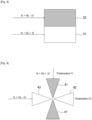
- FIG. 4 illustrates another solution where two radiating parts 41, 42 radiating in orthogonal polarizations are interleaved.
- a first part 41 is reserved for the emission of the first signal f 0 + ⁇ f e + ⁇ f according to the vertical polarization V.
- the second part 42 is reserved for the emission of the second signal f 0 + ⁇ f e - ⁇ f according to the horizontal polarization H.
- the Doppler speed V can be obtained from the measurement of the received frequencies f rec2 , f rec1 to the nearest factor 2 ⁇ f , with very low drift due to the high stability of the source 22. More particularly, the measurement of the speed V is a function of the ratio ( f rec 2 - f rec 1 ) / 2 ⁇ f, the difference 2 ⁇ f between the two carriers on transmission being more precise, more stable, than the nominal transmission frequency f0 .
- T duration counting interval
- ⁇ n 2 ⁇ f vs + V vs ⁇ V T 0 ⁇ T O ⁇ F F ⁇ 2 ⁇ fT 0 1 + 2 V vs 1 ⁇ ⁇ F F ⁇ 2 ⁇ fT 0 1 + 2 V vs ⁇ ⁇ F F by neglecting the second order, we obtain the measurement of the Doppler speed by involving ⁇ f according to the following equation: ⁇ n 2 T 0 ⁇ f ⁇ 1 + 2 V vs ⁇ ⁇ F F
- FIG. 5 presents an example of a block diagram of a reception device according to the invention making it possible to obtain the Doppler speed V as a function of measuring the difference of these two received frequencies (carriers of the signal reflected by the target) and the difference frequency ⁇ f .
- a mixer 53 receives on a first input the reception signal picked up by the reception antenna 52 and receives on a second input a signal coming from a local oscillator 51 at the transposition frequency, close to the transmission frequency, equal f 0 - f FI , the output signal of the mixer being conventionally transposed to the intermediate frequency f FI characterizing heterodyne reception.
- the output signal from the mixer is presented at the input of two band-pass filters 54, 55.
- a first bandpass filter 54 selects the line at the frequency f FI - ⁇ f , transposition of the received carrier which had been transmitted at f 0 + ⁇ f e - ⁇ f .
- a second bandpass filter 55 selects the line at the frequency f FI + ⁇ f , transposition of the received carrier which had been transmitted f 0 + ⁇ f e + ⁇ f .
- Processing means exploit the two lines selected by the bandpass filters to calculate the difference in the received carriers f rec 2 - f rec 1 .
- a high precision clock 57 is used, producing a signal at a frequency F, for the transposition of the two lines into base frequency ( f 0 ). as well as for their sampling in this base frequency.
- the processing means 56 calculate the Doppler speed according to equation (2). We thus obtain the Doppler speed of the targets detected by the reception antenna 51.
- the source 57 must have a sufficient level of stability to sample the signals coming from the filters 54, 55 with precision and consequently to calculate the difference in the frequencies received with precision. Its frequency F is low, in any case lower than the base frequency.
- the transposition of the received signal does not use a high stability source.
- the source used 51 can have a variable frequency, without particular stability, to manage frequency agility.
- Baseband sampling necessary in processing 56 to find the frequency difference (hence the Doppler speed) therefore uses a clock 57 of fixed frequency, rather low, but of high precision. There is not necessarily an interaction between the two sources 51, 57.
- the invention makes it possible to overcome the drift of the local oscillators of each radar, thus eliminating the drift of the local oscillator 21 generating the microwave waves on transmission and the drift of the local oscillator 51 generating microwave waves at reception.
Landscapes
- Engineering & Computer Science (AREA)
- Radar, Positioning & Navigation (AREA)
- Remote Sensing (AREA)
- Computer Networks & Wireless Communication (AREA)
- Physics & Mathematics (AREA)
- General Physics & Mathematics (AREA)
- Radar Systems Or Details Thereof (AREA)
Description
Le domaine technique de l'invention est celui de la détection radar, le domaine d'application concerne les systèmes radar multistatiques comportant au moins M ≥ 1 radars émetteurs et au moins N ≥ 1 radar récepteurs. L'invention s'applique à des radars fixes au sol, à des radars aéroportés, navals ou spatiaux, plus généralement mobiles, voire à une combinaison des deux types.The technical field of the invention is that of radar detection, the field of application concerns multistatic radar systems comprising at least M ≥ 1 transmitting radars and at least N ≥ 1 receiving radars. The invention applies to fixed ground radars, to airborne, naval or space radars, more generally mobile, or even to a combination of the two types.
On connaît dans ce domaine technique la demande de brevet
Pour la simplification de l'exposé, dans la suite de la description les radars sont supposés fixes, avec N = M = 1 (système bi-statique) mais le principe et aisément généralisable à des radars mobiles et aussi en plus grand nombre.For the simplification of the presentation, in the remainder of the description the radars are assumed to be fixed, with N = M = 1 (bi-static system) but the principle can easily be generalized to mobile radars and also in larger numbers.
Un inconvénient du radar mono-statique (cas où l'émetteur et le récepteur sont sur un même site) est son manque de discrétion, donc sa vulnérabilité. En effet le radar qui effectue la détection, la localisation et la mesure de vitesse de la cible est aussi celui qui émet le signal et qui est détectable par un système d'écoute adverse. Les systèmes bi-statiques évitent cette vulnérabilité.A disadvantage of mono-static radar (case where the transmitter and receiver are on the same site) is its lack of discretion, and therefore its vulnerability. In fact, the radar which performs the detection, localization and speed measurement of the target is also the one which emits the signal and which is detectable by an opposing listening system. Bi-static systems avoid this vulnerability.
La
La contrepartie de cette séparation physique est que les radars E et R doivent nécessairement disposer chacun de leur propre oscillateur local et donc de leur propre base de temps. Ces oscillateurs présentent inévitablement des dérives différentielles en fréquence. Par exemple si on veut opérer le système radar bi-statique sur la fréquence porteuse f 0 :
- Le signal émis ne sera pas exactement à la fréquence f 0 mais à la fréquence

- La fréquence centrale de réception (définie par l'oscillateur locale de démodulation en réception) ne sera pas non plus exactement à la fréquence f 0 mais à la fréquence fR = f 0 + δfr.
- The signal emitted will not be exactly at the frequency f 0 but at the frequency
- The central reception frequency (defined by the local reception demodulation oscillator) will also not be exactly at the frequency f 0 but at the frequency f R = f 0 + δf r .
Dans le cas d'un système mono-statique utilisant la même source de fréquence on a δfe = δfr, et ces dérivent s'annulent entre elles, ce qui n'est plus le cas d'un système bi-statique.In the case of a mono-static system using the same frequency source we have δf e = δf r , and these drifts cancel each other out, which is no longer the case for a bi-static system.
Si la cible est affectée d'une « vitesse Doppler » produisant un effet Doppler fD, le récepteur mesure en réalité une fréquence Doppler biaisée : ![]()
![]()
Par exemple, supposons un radar fonctionnant en bande X à f 0 = 10 Ghz et des oscillateurs locaux dont la précision relative est de 10-6. Cela signifie que fE et fR sont définies à 1010 x 10-6 = 10000 Hz près : en bande X, une telle erreur Doppler correspond à une erreur en vitesse Doppler d'environ 150 m/s ( ![]()
![]()
II est à noter que dans le cas d'un système bi-statique, l'homme du métier sait que cette « vitesse Doppler » VD est la projection du vecteur vitesse VC de la cible sur la bissectrice 10 de l'angle ![]()
![]()
On peut imaginer réduire ce biais en vitesse en utilisant des oscillateurs ayant une bien meilleure stabilité. Par exemple un oscillateur de stabilité relative de 10-8 permet de ramener l'erreur en vitesse à 1.5 m/s, ce qui peut constituer une erreur acceptable. Cependant dans le cas d'un système radar, en particulier fonctionnant en ondes centimétriques ou millimétriques, et où le critère de cout du matériel est très important, une telle solution s'avère rapidement trop onéreuse, les oscillateurs à très haute fréquence et haute stabilités étant très onéreux.We can imagine reducing this speed bias by using oscillators with much better stability. For example, a relative stability oscillator of 10 -8 makes it possible to reduce the speed error to 1.5 m/s, which can constitute an acceptable error. However, in the case of a radar system, in particular operating in centimeter or millimeter waves, and where the cost criterion of hardware is very important, such a solution quickly proves too expensive, very high frequency and high stability oscillators being very expensive.
Plusieurs méthodes sont connues de l'art antérieur pour remédier aux problèmes précédents. Dans une première méthode on réalise l'asservissement des oscillateurs locaux et des bases de temps de chaque radar sur un signal de référence commun, par exemple le signal GPS (plus généralement GNSS). On parle ainsi de « GNSS disciplined référence ». Cette solution est couramment employée dans les systèmes radar multistatiques non-critiques, c'est-à-dire pour lesquels on peut faire l'hypothèse que le signal GNSS (GPS) sera toujours disponible, non brouillé ou non intentionnellement faussé localement. Toutefois, la réalisation d'un oscillateur ayant une pureté spectrale satisfaisante (nécessaire pour obtenir une visibilité sous le fouillis de sol suffisante) tout en étant asservi sur un signal GNSS de très faible rapport S/B est complexe.Several methods are known from the prior art to remedy the preceding problems. In a first method, the local oscillators and time bases of each radar are controlled by a common reference signal, for example the GPS signal (more generally GNSS). We therefore speak of “GNSS disciplined reference”. This solution is commonly used in non-critical multistatic radar systems, that is to say for which it can be assumed that the GNSS signal (GPS) will always be available, not jammed or not intentionally distorted locally. However, producing an oscillator having satisfactory spectral purity (necessary to obtain sufficient visibility under ground clutter) while being controlled by a GNSS signal with a very low S/N ratio is complex.
Dans une deuxième méthode, on réalise la transmission de la réplique du signal émis directement de l'émetteur vers le récepteur. Cette solution est utilisée dans le cas des systèmes multistatiques non-coopératifs tels que ceux utilisant les signaux de télédiffusion (radars « PCL » = Passive Cohérent Locator). Là encore, le système est vulnérable au brouillage ou à l'attaque de la transmission de la réplique du signal émis. Il faut également que les conditions de visibilité de E vu de R permettent la transmission de la réplique avec un rapport signal à bruit suffisant. De plus, le traitement à mettre en oeuvre est complexe.In a second method, the replica of the transmitted signal is transmitted directly from the transmitter to the receiver. This solution is used in the case of non-cooperative multistatic systems such as those using television broadcast signals (“PCL” radars = Passive Coherent Locator). Here again, the system is vulnerable to jamming or attack on the transmission of the replica of the transmitted signal. The visibility conditions of E seen from R must also allow the transmission of the replica with a sufficient signal-to-noise ratio. In addition, the treatment to be implemented is complex.
Dans une troisième méthode, on réalise l'asservissement des oscillateurs locaux et des bases de temps de chaque radar (horloges atomiques locales ultra-stables). C'est la solution de référence pour les systèmes critiques car elle ne repose pas sur la réception d'un signal tiers et seules quelques données doivent être échangées ou planifiées entre les radars E et R, ce qui permet d'utiliser un lien simple et durci entre les plateformes. C'est en revanche une solution complexe et coûteuse à mettre en oeuvre.In a third method, the local oscillators and time bases of each radar are controlled (ultra-stable local atomic clocks). It is the reference solution for critical systems because it does not rely on the reception of a third-party signal and only some data must be exchanged or scheduled between the E and R radars, which allows the use of a simple and hardened between platforms. On the other hand, it is a complex and expensive solution to implement.
Un but de l'invention est de pallier les inconvénients précités et notamment de permettre la mise en oeuvre d'une solution non complexe et non coûteuse. A cet effet, l'invention a pour objet un procédé de mesure de la vitesse Doppler d'une cible détectée par un dispositif radar multistatique comportant au moins un premier radar générant un signal d'émission vers ladite cible et un deuxième radar recevant le signal rétrodiffusé par ladite cible. Le deuxième radar a connaissance :
- de coordonnées du premier radar,
- d'un vecteur vitesse du premier radar,
- d'une direction illuminée par le premier radar,
- d'une fréquence centrale d'émission utilisée par le premier radar,
- d'une forme d'onde utilisée par le premier radar,
- coordinates of the first radar,
- a speed vector of the first radar,
- from a direction illuminated by the first radar,
- a central transmission frequency used by the first radar,
- a waveform used by the first radar,
Dans le procédé selon l'invention, on génère à l'émission deux ondes porteuses ayant un écart fréquentiel donné, l'écart fréquentiel étant connu du deuxième radar, la mesure de la vitesse Doppler en réception étant fonction de la différence des fréquences de réception desdites ondes porteuses divisée par ledit écart fréquentiel.In the method according to the invention, two carrier waves are generated on transmission having a given frequency difference, the frequency difference being known to the second radar, the measurement of the Doppler speed in reception being a function of the difference in the reception frequencies of said carrier waves divided by said frequency difference.
Les deux ondes porteuses sont par exemple générées à l'émission par mélange d'une onde de fréquence voisine de la fréquence d'émission et d'une onde de plus basse fréquence fixe et plus stable en fréquence que ladite fréquence d'émission.The two carrier waves are for example generated on transmission by mixing a wave of frequency close to the transmission frequency and a wave of lower fixed frequency and more stable in frequency than said transmission frequency.
L'antenne d'émission est par exemple délimitée en au moins deux parties, une première partie étant dédiée à l'émission d'une onde porteuse et une deuxième partie étant dédiée à l'émission de l'autre onde porteuse.The transmitting antenna is for example delimited into at least two parts, a first part being dedicated to the emission of a carrier wave and a second part being dedicated to the emission of the other carrier wave.
Dans un autre mode de mise en oeuvre possible, l'onde porteuse est émise selon une polarisation, l'autre onde porteuse étant émise sur une autre polarisation.In another possible mode of implementation, the carrier wave is emitted according to one polarization, the other carrier wave being emitted on another polarization.
A la réception, la transposition en fréquence des signaux de réception desdites ondes porteuses réfléchies par ladite cible est par exemple réalisée en les mélangeant avec une onde de fréquence voisine de ladite fréquence d'émission fournie par une première horloge. Ladite différence des fréquences de réception desdites porteuses réfléchies par ladite cible est par exemple mesurée à la réception en utilisant une deuxième horloge plus précise que ladite première horloge. Les deux horloges sont par exemple indépendantes.On reception, the frequency transposition of the reception signals of said carrier waves reflected by said target is for example carried out by mixing them with a wave of frequency close to said transmission frequency provided by a first clock. Said difference in the reception frequencies of said carriers reflected by said target is for example measured upon reception using a second clock more precise than said first clock. The two clocks are for example independent.
D'autres caractéristiques et avantages de l'invention apparaîtront à l'aide de la description qui suit, faite en regard de dessins annexés qui représentent :
- [
Fig.1 ] lafigure 1 déjà décrite, une illustration d'une géométrie bi-statique ; - [
Fig.2 ] lafigure 2 , un exemple de génération de signal à deux ton utilisé dans le procédé selon l'invention ; - [
Fig.3 ] lafigure 3 , un exemple d'antenne d'émission partionnée en deux ; - [
Fig.4 ] lafigure 4 , un exemple d'antenne partionnée selon la polarisation ; - [
Fig.5 ] lafigure 5 , un synoptique d'un exemple de circuit de réception utilisé pour la mise en oeuvre du procédé selon l'invention.
- [
Fig.1 ] therefigure 1 already described, an illustration of a bi-static geometry; - [
Fig.2 ] therefigure 2 , an example of two-tone signal generation used in the method according to the invention; - [
Fig.3 ] thereFigure 3 , an example of a transmitting antenna partitioned in two; - [
Fig.4 ] thereFigure 4 , an example of an antenna partitioned according to polarization; - [
Fig.5 ] thereFigure 5 , a block diagram of an example of a reception circuit used for implementing the method according to the invention.
Pour décrire l'invention, on commence par décrire la partie émission d'un radar bi-statique, située sur un site, puis on décrira la partie réception située sur un site physiquement éloigné, les sites pouvant être des plateformes aéroportées par exemple. Pour la partie émission on décrit la nature des signaux émis puis des spécificités apportées à l'antenne.To describe the invention, we begin by describing the transmission part of a bi-static radar, located on a site, then we will describe the reception part located on a physically distant site, the sites being able to be airborne platforms for example. For the transmission part, we describe the nature of the signals transmitted and then the specificities provided to the antenna.
La
Une première source 21 générant directement une onde de fréquence f 0 + δfe proche de la fréquence d'émission du radar mais dont la stabilité relative n'a pas nécessairement besoin d'être précise (notamment pour éviter un surcoût) : par exemple une stabilité de 10-6 voire une stabilité moindre (δf e étant l'erreur sur la fréquence de la source à f 0).Cette source 21 peut avoir une fréquence ajustable pour permettre l'agilité de fréquence d'émission.Une seconde source 22 de fréquence fixe Δf nettement plus basse (par exemple de l'ordre du GHz) mais dont la stabilité relative est nettement meilleure :par exemple 10-8.
- A
first source 21 directly generating a wave of frequency f 0 + δf e close to the radar transmission frequency but whose relative stability does not necessarily need to be precise (in particular to avoid additional cost): for example a stability of 10 -6 or even less stability ( δf e being the error on the frequency of the source at f 0 ). Thissource 21 can have an adjustable frequency to allow transmission frequency agility. - A
second source 22 of fixed frequency Δ f significantly lower (for example of the order of GHz) but whose relative stability is significantly better: for example 10 -8 .
Comme on le verra par la suite, l'invention utilise avantageusement cette source de fréquence fixe Δf pour extraire la vitesse Doppler, cette source de fréquence étant à plus basse fréquence peut être à haute stabilité sans surcoût excessif.As will be seen subsequently, the invention advantageously uses this fixed frequency source Δ f to extract the Doppler speed, this frequency source being at a lower frequency can be at high stability without excessive additional cost.
A partir de ces deux sources on génère un signal porteur à deux tons, au moyen d'un mélangeur équilibré 23, dont les entrées sont les sorties des deux sources 21, 22, et de deux filtres passe-bande 24, 25. La sortie du mélangeur donne le signal :
Ce signal constitue l'entrée de chacun des deux filtres, la sortie du premier filtre 24 et la sortie du deuxième filtre 25 étant respectivement :
D'autres modes de réalisation peuvent être utilisés pour générer ce signal porteur à partir des deux sources 21, 22, permettant dans certain cas de s'affranchir des filtres passe-bande 24 et 25, comme par exemple un mélangeur équilibré en régime linéaire qui délivre sur ses deux sorties directement les signaux sinusoïdaux correspondant aux mélanges additif et soustractif des fréquences de deux signaux à f0 + δfe et Δf. La nécessité de l'opération de séparation des deux tons dépend de l'aptitude du dispositif d'émission à émettre un signal multitons (amplification linéaire ou saturée).Other embodiments can be used to generate this carrier signal from the two
Le terme « k » est un entier positif supérieur ou égal à 1 qui correspond aux harmoniques du signal de mélange de fréquence Δf. Les deux filtres passe-bande 24, 25 en sortie permettent de ne retenir que les deux raies porteuses désirées.The term “ k ” is a positive integer greater than or equal to 1 which corresponds to the harmonics of the frequency mixing signal Δ f . The two
A une constante multiplicative près, le signal rayonné à l'émission est ainsi la somme des deux signaux : ![]()

![]()
La relation précédente montre que l'enveloppe du signal émis autour de f 0 ne possède pas une amplitude constante mais une amplitude variable selon A = 2|cos(2πΔft + ϕ/2)| . Ceci peut compliquer l'émission du signal avec des dispositifs d'émission fonctionnant en régime saturé, inaptes à transmettre l'intégralité de l'amplitude du signal. Pour surmonter cet inconvénient, on ne réalise pas la somme des deux composantes sinusoïdales dans les circuits d'émission, mais dans l'espace de propagation. Les
La
La
On décrit maintenant la partie réception en commençant par la problématique de la mesure de la vitesse Doppler.We now describe the reception part starting with the problem of measuring the Doppler speed.
On considère une cible de vitesse Doppler V (projection de son vecteur vitesse sur la bissectrice 10 de l'angle ![]()
- La porteuse à f 0 + δfe - Δf est reçue à

- La porteuse à f 0 + δfe + Δf est reçue à

- The carrier at f 0 + δf e - Δf is received at
- The carrier at f 0 + δf e + Δf is received at
Etant donné que V est très inférieure à la vitesse de propagation c, on a ![]()
![]()
Pour s'affranchir de l'erreur de fréquence inconnue δfe, il faut éliminer ce terme dans la mesure, par exemple en mesurant l'écart de fréquence : ![]()
![]()
Cette relation montre que l'on peut obtenir la vitesse Doppler V à partir de la mesure des fréquences reçues frec2, frec1 au facteur 2Δf près, à très faible dérive en raison de la haute stabilité de la source 22. Plus particulièrement, la mesure de la vitesse V est fonction du rapport (f rec2 - f rec1 )/ 2Δf , l'écart 2Δf entre les deux porteuses à l'émission étant plus précis, plus stable, que la fréquence d'émission nominale f 0.This relationship shows that the Doppler speed V can be obtained from the measurement of the received frequencies f rec2 , f rec1 to the nearest factor 2Δ f , with very low drift due to the high stability of the
Pour mesurer les deux fréquences précédentes f rec2, f rec1 on peut, par exemple, compter le nombre de périodes de chacune durant un temps suffisamment long T. On a ainsi : n 1 = Tf rec1 et n 2 = Tf rec2 et par ![]()
![]()
Un problème est que l'intervalle de comptage de durée T est nécessairement élaboré à bord du radar récepteur avec une horloge disponible à bord. Cette horloge présente inévitablement une dérive par rapport à la valeur exacte. Soit F cette fréquence théorique et F + δF sa fréquence effective. Si T est déterminé par Q périodes de cette fréquence, sa valeur effective est ![]()
![]()
![]()
![]()
On mesure par conséquent : ![]()
![]()
![]()
![]()
Cette équation montre que l'erreur minimale sur ![]()
![]()
![]()
![]()
En négligeant l'erreur sur la fréquence F, la vitesse V est obtenue selon l'équation suivante : ![]()
![]()
![]()
![]()
La
Un mélangeur 53 reçoit sur une première entrée le signal de réception capté par l'antenne de réception 52 et reçoit sur une deuxième entrée un signal issu d'un oscillateur local 51 à la fréquence de transposition, voisine de la fréquence d'émission, égale f 0 - fFI, le signal de sortie du mélangeur étant classiquement transposé à la fréquence intermédiaire fFI caractérisant une réception hétérodyne. Le signal de sortie du mélangeur est présenté en entrée de deux filtres passe-bande 54, 55.A
Un premier filtre passe-bande 54 sélectionne la raie à la fréquence fFI - Δf, transposition de la porteuse reçue qui avait été émise à f 0 + δfe - Δf.A
Un deuxième filtre passe-bande 55 sélectionne la raie à la fréquence fFI + Δf, transposition de la porteuse reçue qui avait été émise f 0 + δf e + Δf.A
Des moyens de traitement exploitent les deux raies sélectionnées par les filtres passe-bande pour calculer la différence des porteuses reçues f rec2 - f rec1 . A cet effet, on utilise une horloge 57, de haute précision, produisant un signal à une fréquence F, pour la transposition des deux raies en fréquence de base (f 0) ainsi que pour leur échantillonnage dans cette fréquence de base. Les moyens de traitement 56 calculent la vitesse Doppler conformément à l'équation (2). On obtient ainsi la vitesse Doppler des cibles détectées par l'antenne de réception 51.Processing means exploit the two lines selected by the bandpass filters to calculate the difference in the received carriers f rec 2 - f rec 1 . For this purpose, a
La source 57 doit avoir un niveau de stabilité suffisant pour échantillonner les signaux issus des filtres 54, 55 avec précision et par conséquence pour calculer la différence des fréquences reçues avec précision. Sa fréquence F est basse, en tous cas plus faible que la fréquence de base.The
Avantageusement, la transposition du signal reçu (récepteur hétérodyne 51, 53) ne fait pas appel à une source de haute stabilité. La source utilisée 51 peut avoir une fréquence variable, sans stabilité particulière, pour gérer l'agilité de fréquence.Advantageously, the transposition of the received signal (
L'échantillonnage en bande de base, nécessaire dans le traitement 56 pour retrouver l'écart de fréquence (donc la vitesse Doppler) utilise donc une horloge 57 de fréquence fixe, plutôt faible, mais de haute précision. Il n'y a pas nécessairement d'interaction entre les deux sources 51, 57.Baseband sampling, necessary in processing 56 to find the frequency difference (hence the Doppler speed) therefore uses a
Avantageusement, l'invention permet de s'affranchir de la dérive des oscillateurs locaux de chaque radar, s'affranchissant ainsi de la dérive de l'oscillateur local 21 générant les ondes hyperfréquence à l'émission et de la dérive de l'oscillateur local 51 générant les ondes hyperfréquence à la réception.Advantageously, the invention makes it possible to overcome the drift of the local oscillators of each radar, thus eliminating the drift of the
Des données doivent être transmises du radar émetteur vers le radar récepteur pour coordonner leurs fonctionnements, ces données sont notamment les suivantes :
- Coordonnées (X, Y,Z) du radar émetteur ;
- Vecteur vitesse (Vx, Vy, Vz) du radar émetteur ;
- Direction illuminée par le radar émetteur : par exemple deux cosinus directeurs (Uy, Uz) ;
- Indication permettant de connaître la fréquence centrale f 0 ;
- Indication éventuelle permettant de connaître l'écart entre porteuses ΔF ;
- Indications concernant la forme d'onde utilisée.
- Coordinates ( X, Y,Z ) of the transmitting radar;
- Speed vector ( Vx, Vy, Vz ) of the transmitting radar;
- Direction illuminated by the transmitting radar: for example two direction cosines ( Uy, Uz ) ;
- Indication allowing you to know the central frequency f 0 ;
- Possible indication allowing the separation between carriers Δ F to be known;
- Indications regarding the waveform used.
Ces échanges de données sont à bas débit moyen (quelques kbits/s en moyenne). On peut remarquer qu'il n'est pas forcément nécessaire qu'il y ait un retour d'information du radar récepteur vers le radar émetteur, ce qui favorise la discrétion du système.These data exchanges are at a low average speed (a few kbits/s on average). It can be noted that it is not necessarily necessary for there to be a feedback from the receiving radar to the transmitting radar, which promotes the discretion of the system.
Claims (7)
- A method for measuring the Doppler velocity of a target detected by a multistatic radar device comprising at least one first radar (E) generating a transmission signal towards said target (C) and a second radar (R) receiving the signal backscattered by said target, with the second radar knowing:- the coordinates of the first radar;- a velocity vector of the first radar;- a direction illuminated by the first radar;- a central transmission frequency (f0) used by the first radar;- a waveform used by the first radar;wherein two carrier waves with a given frequency deviation (2Δf) are generated (23, 24, 25) on transmission, with the second radar knowing said frequency deviation, the method for measuring the Doppler velocity of a target being characterised in that measuring the Doppler velocity on reception is a function of the difference in the reception frequencies of said carrier waves divided by said frequency deviation (2Δf).
- The method according to claim 1, wherein the two carrier waves are generated on transmission by mixing (23) a wave whose frequency is close to the transmission frequency (21) and a wave (22) with a lower frequency that is fixed and is more frequency stable than said transmission frequency.
- The method according to any one of the preceding claims, wherein the transmission antenna of said first radar is divided into at least two parts (31, 32), a first part (31) is intended for transmitting a carrier wave and a second part (32) is intended for transmitting the other carrier wave.
- The method according to any one of claims 1 or 2, wherein a carrier wave is transmitted with a polarisation (41), with the other carrier wave being transmitted with another polarisation (42).
- The method according to any one of the preceding claims, wherein, on reception, the frequency transposition of the reception signals of said carrier waves reflected by said target (C) is carried out by mixing (53) them with a wave whose frequency is close to said transmission frequency supplied by a first clock (51).
- The method according to claim 5, wherein said difference in the reception frequencies of said carrier waves reflected by said target (C) is measured on reception using a second clock (57) that is more accurate than said first clock (51).
- The method according to claim 6, wherein the two clocks are independent.
Applications Claiming Priority (2)
| Application Number | Priority Date | Filing Date | Title |
|---|---|---|---|
| FR1914853A FR3105437B1 (en) | 2019-12-19 | 2019-12-19 | DOPPLER MEASUREMENT PROCEDURE FOR MULTISTATIC RADAR DEVICE, RADAR DEVICE IMPLEMENTING SUCH A PROCESS |
| PCT/EP2020/083921 WO2021121928A1 (en) | 2019-12-19 | 2020-11-30 | Doppler measurement method for multistatic radar device, radar device implementing such a method |
Publications (2)
| Publication Number | Publication Date |
|---|---|
| EP4078227A1 EP4078227A1 (en) | 2022-10-26 |
| EP4078227B1 true EP4078227B1 (en) | 2024-02-21 |
Family
ID=71094414
Family Applications (1)
| Application Number | Title | Priority Date | Filing Date |
|---|---|---|---|
| EP20812061.8A Active EP4078227B1 (en) | 2019-12-19 | 2020-11-30 | Doppler measurement method for multistatic radar device, radar device implementing such a method |
Country Status (3)
| Country | Link |
|---|---|
| EP (1) | EP4078227B1 (en) |
| FR (1) | FR3105437B1 (en) |
| WO (1) | WO2021121928A1 (en) |
Family Cites Families (4)
| Publication number | Priority date | Publication date | Assignee | Title |
|---|---|---|---|---|
| NO921193D0 (en) * | 1992-03-26 | 1992-03-26 | Susar As | SYSTEM FOR DETECTION, MEASUREMENT AND CLASSIFICATION OF AIR PHENOMES |
| DE102004060087A1 (en) * | 2004-12-14 | 2006-06-22 | Robert Bosch Gmbh | Device for especially bistatic radar applications |
| FR2968406B1 (en) * | 2010-12-03 | 2013-04-12 | Thales Sa | SYSTEM FOR MEASURING THE RADIAL SPEED OF A MOBILE |
| US10203405B2 (en) * | 2013-04-25 | 2019-02-12 | The United States Of America As Represented By The Secretary Of The Army | Multitone radar with range determination and method of use |
-
2019
- 2019-12-19 FR FR1914853A patent/FR3105437B1/en active Active
-
2020
- 2020-11-30 EP EP20812061.8A patent/EP4078227B1/en active Active
- 2020-11-30 WO PCT/EP2020/083921 patent/WO2021121928A1/en unknown
Also Published As
| Publication number | Publication date |
|---|---|
| FR3105437B1 (en) | 2021-12-10 |
| FR3105437A1 (en) | 2021-06-25 |
| WO2021121928A1 (en) | 2021-06-24 |
| EP4078227A1 (en) | 2022-10-26 |
Similar Documents
| Publication | Publication Date | Title |
|---|---|---|
| US11366228B2 (en) | Method and system for time separated quadrature detection of doppler effects in optical range measurements | |
| US11567351B2 (en) | Methods for computation-free wideband spectral correlation and analysis | |
| JP6558918B2 (en) | Minus pseudo range processing using multistatic FMCW radar | |
| EP0258917B1 (en) | Frequency-modulated continuous-wave radar for distance measurement | |
| EP0575221B1 (en) | Method for eliminating the signals of obstacles by radar and its applications | |
| EP0118342B1 (en) | Fm continuous wave radar and its application to an altimeter | |
| EP3436845A1 (en) | Direct detection lidar system and method with frequency modulation (fm) transmitter and quadrature receiver | |
| FR3058227A1 (en) | FLEXW MULTIFUNCAL RADAR, IN PARTICULAR FOR AUTOMOBILE | |
| FR2722005A1 (en) | APPARATUS AND METHOD FOR ATTENUATING AMBIGUITS IN PULSE DOPPLER RADARS | |
| US20040150548A1 (en) | Linear frequency modulation superimposed on double sideband diplex radar | |
| US20040046689A1 (en) | Signal processing | |
| EP1096269A2 (en) | Heterodyned double sideband diplex radar | |
| US11555881B2 (en) | Locating method for localizing at least one object using wave-based signals and locating system | |
| EP0143497B1 (en) | Axis-stable fmcw monopulse radar system | |
| Scotti et al. | Multi-frequency lidar/radar integrated system for robust and flexible doppler measurements | |
| JP2019090791A (en) | Location determination of emitter using arrival frequency (foa) measured from single mobile platform | |
| EP3171195A2 (en) | Method for locating a beacon | |
| EP4078227B1 (en) | Doppler measurement method for multistatic radar device, radar device implementing such a method | |
| JPH0743453A (en) | Short wave radar device | |
| Sandström et al. | A study of some FMCW radar algorithms for target location at low frequencies | |
| EP2410350A1 (en) | Antenna device with synthetic opening for emitting signals of a satellite navigation system including a carrier and a means for determining the trajectory thereof | |
| FR3058530A1 (en) | METHOD FOR CONTROLLING THE ELECTROMAGNETIC COMPATIBILITY OF A RADAR DETECTOR WITH AT LEAST ONE IMPULSE SIGNAL EDGE TRANSMITTER | |
| EP2341363A1 (en) | System for responding to a signal emitted by a radar and use of said system mainly for testing radars, in particular MTI radars | |
| EP3538917B1 (en) | Method for testing the electromagnetic compatibility of a radar detector with at least one onboard pulse signal transmitter | |
| Laghezza et al. | Integrated multi-frequency lidar/radar system for precise and robust Doppler measurements |
Legal Events
| Date | Code | Title | Description |
|---|---|---|---|
| STAA | Information on the status of an ep patent application or granted ep patent |
Free format text: STATUS: UNKNOWN |
|
| STAA | Information on the status of an ep patent application or granted ep patent |
Free format text: STATUS: THE INTERNATIONAL PUBLICATION HAS BEEN MADE |
|
| PUAI | Public reference made under article 153(3) epc to a published international application that has entered the european phase |
Free format text: ORIGINAL CODE: 0009012 |
|
| STAA | Information on the status of an ep patent application or granted ep patent |
Free format text: STATUS: REQUEST FOR EXAMINATION WAS MADE |
|
| 17P | Request for examination filed |
Effective date: 20220523 |
|
| AK | Designated contracting states |
Kind code of ref document: A1 Designated state(s): AL AT BE BG CH CY CZ DE DK EE ES FI FR GB GR HR HU IE IS IT LI LT LU LV MC MK MT NL NO PL PT RO RS SE SI SK SM TR |
|
| DAV | Request for validation of the european patent (deleted) | ||
| DAX | Request for extension of the european patent (deleted) | ||
| P01 | Opt-out of the competence of the unified patent court (upc) registered |
Effective date: 20230427 |
|
| GRAP | Despatch of communication of intention to grant a patent |
Free format text: ORIGINAL CODE: EPIDOSNIGR1 |
|
| STAA | Information on the status of an ep patent application or granted ep patent |
Free format text: STATUS: GRANT OF PATENT IS INTENDED |
|
| INTG | Intention to grant announced |
Effective date: 20231129 |
|
| GRAS | Grant fee paid |
Free format text: ORIGINAL CODE: EPIDOSNIGR3 |
|
| GRAA | (expected) grant |
Free format text: ORIGINAL CODE: 0009210 |
|
| STAA | Information on the status of an ep patent application or granted ep patent |
Free format text: STATUS: THE PATENT HAS BEEN GRANTED |
|
| AK | Designated contracting states |
Kind code of ref document: B1 Designated state(s): AL AT BE BG CH CY CZ DE DK EE ES FI FR GB GR HR HU IE IS IT LI LT LU LV MC MK MT NL NO PL PT RO RS SE SI SK SM TR |
|
| RAP3 | Party data changed (applicant data changed or rights of an application transferred) |
Owner name: THALES |
|
| REG | Reference to a national code |
Ref country code: GB Ref legal event code: FG4D Free format text: NOT ENGLISH |
|
| REG | Reference to a national code |
Ref country code: CH Ref legal event code: EP |
|
| REG | Reference to a national code |
Ref country code: DE Ref legal event code: R096 Ref document number: 602020026158 Country of ref document: DE |
|
| REG | Reference to a national code |
Ref country code: IE Ref legal event code: FG4D Free format text: LANGUAGE OF EP DOCUMENT: FRENCH |