EP4067264A1 - Sorting device - Google Patents
Sorting device Download PDFInfo
- Publication number
- EP4067264A1 EP4067264A1 EP21166762.1A EP21166762A EP4067264A1 EP 4067264 A1 EP4067264 A1 EP 4067264A1 EP 21166762 A EP21166762 A EP 21166762A EP 4067264 A1 EP4067264 A1 EP 4067264A1
- Authority
- EP
- European Patent Office
- Prior art keywords
- boxes
- gripper
- transport device
- storage
- loading area
- Prior art date
- Legal status (The legal status is an assumption and is not a legal conclusion. Google has not performed a legal analysis and makes no representation as to the accuracy of the status listed.)
- Withdrawn
Links
Images


Classifications
-
- B—PERFORMING OPERATIONS; TRANSPORTING
- B65—CONVEYING; PACKING; STORING; HANDLING THIN OR FILAMENTARY MATERIAL
- B65G—TRANSPORT OR STORAGE DEVICES, e.g. CONVEYORS FOR LOADING OR TIPPING, SHOP CONVEYOR SYSTEMS OR PNEUMATIC TUBE CONVEYORS
- B65G1/00—Storing articles, individually or in orderly arrangement, in warehouses or magazines
- B65G1/02—Storage devices
- B65G1/04—Storage devices mechanical
- B65G1/0471—Storage devices mechanical with access from beneath
-
- B—PERFORMING OPERATIONS; TRANSPORTING
- B65—CONVEYING; PACKING; STORING; HANDLING THIN OR FILAMENTARY MATERIAL
- B65G—TRANSPORT OR STORAGE DEVICES, e.g. CONVEYORS FOR LOADING OR TIPPING, SHOP CONVEYOR SYSTEMS OR PNEUMATIC TUBE CONVEYORS
- B65G1/00—Storing articles, individually or in orderly arrangement, in warehouses or magazines
- B65G1/02—Storage devices
- B65G1/04—Storage devices mechanical
- B65G1/137—Storage devices mechanical with arrangements or automatic control means for selecting which articles are to be removed
- B65G1/1373—Storage devices mechanical with arrangements or automatic control means for selecting which articles are to be removed for fulfilling orders in warehouses
- B65G1/1378—Storage devices mechanical with arrangements or automatic control means for selecting which articles are to be removed for fulfilling orders in warehouses the orders being assembled on fixed commissioning areas remote from the storage areas
-
- B—PERFORMING OPERATIONS; TRANSPORTING
- B65—CONVEYING; PACKING; STORING; HANDLING THIN OR FILAMENTARY MATERIAL
- B65G—TRANSPORT OR STORAGE DEVICES, e.g. CONVEYORS FOR LOADING OR TIPPING, SHOP CONVEYOR SYSTEMS OR PNEUMATIC TUBE CONVEYORS
- B65G60/00—Simultaneously or alternatively stacking and de-stacking of articles
-
- B—PERFORMING OPERATIONS; TRANSPORTING
- B65—CONVEYING; PACKING; STORING; HANDLING THIN OR FILAMENTARY MATERIAL
- B65G—TRANSPORT OR STORAGE DEVICES, e.g. CONVEYORS FOR LOADING OR TIPPING, SHOP CONVEYOR SYSTEMS OR PNEUMATIC TUBE CONVEYORS
- B65G65/00—Loading or unloading
Definitions
- the present invention relates to a sorting device according to claim 1.
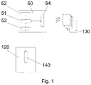
- the automated box storage system and/or organization system preferably includes a control module 50 and/or a storage system 110 and/or a box/tray sorting area 120.
- Control module 50 has a central control processor 51 and/or an order processing unit 52 and/or an interface 53 and/or a wireless interface 54, preferably to device 120 and/or 140.
- Several mobile transport devices 130 can be controlled by a central processor 50 via a wireless interface 54 and/or are provided, both empty and full boxes/trays as well as stacked boxes/trays 101 ( figure 5 ) both within the storage system 110 and (and/or) in the sorting area of the shells 120 and to transport between the areas mentioned.
- the box/tray sorting area 120 there is at least one, preferably at least two, devices for lifting 140/142 stacks of boxes/trays 130.
- the device 140/142 can be designed to lift boxes/trays from a transport device, preferably in the sorting area. All boxes/trays as well as a subset of boxes/trays can be lifted or picked up by the transport device.
- the box/tray sortation area 120 may contain multiple buffer locations to accommodate multiple TMUs 130 or their boxes in the event that they arrive early and await further processing.
- the storage area of stacked shells 110 can be multi-tiered with several separate stacks 110 one above the other.
- the transport device 130 shown preferably comprises a lifting table 131, which is designed for receiving and transporting trays/boxes 101 or stacks of trays/boxes thereof, and two groups of drive wheels 132 and 133, which are intended to move the device in two mutually perpendicular horizontal directions.
- the structural design of the TMU 130 or the storage facility 110 is produced in such a way that an empty device 130 with its lifting table 131 without trays/boxes located/transported on it can be moved freely in the storage area 110 underneath the stacks.
- the TMU can also be delivered to stacks that are located in areas of the memory area that are further back are located without having to drive around the storage area itself.
- the mobile transport device 130 which is preferably part of the storage and sorting system according to the invention, can be controlled in any known manner.
- an embedded (industrial) controller 134 with a wireless interface 135 for communication with the central processor 51 of the automatic system can be used for the controller.
- the controller 134 controls the drivers 136 of the drives of the wheels 132 and 133 for movement, preferably along rails, in preferably two directions in one plane and/or the driver 137 of the vertical position of the wheels 132, 133, above which the wheels are raised can be and thereby the underside of the lifting table can touch the ground and / or the state of the lifting table 131 (height adjustability).
- the rails can be present in the storage area 110 and/or in the sorting area, ie also between the areas, connecting them and can be provided as a basis for the movement of the transport devices 130 .
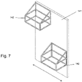
- a device 140 for lifting single or stacks of boxes/trays is shown with a (base) body 141 and at least two grippers 142 moving in vertical direction relative to the body 141 and gripping/picking up and lifting any number of boxes/trays 101 from or onto a TMU 130 in the operating range of the grippers 142.
- the TMU for picking up/gripping the boxes/trays by a gripper is below the gripper.
- the gripper may be provided with a frame dimensioned to fit over a stack of boxes.
- the grippers can be equipped with retaining elements/retaining lugs/retaining brackets or other devices that can be adjusted to the shells/boxes, which are designed boxes/shells 101, which the gripper (pushed over, see e.g. 8 ) are delivered to hold the gripper 142.
- the device for lifting stacks of trays 140 can also be controlled in any known manner.
- an embedded industrial controller 143 having an interface 144 for communication with the central processor 51 of the automated system 100 can be used.
- the controller 143 controls the drivers 145 and 146 of the respective gripper drives 142 for picking up and lifting the (stack of) tray(s)/box(es) 101 in the vertical direction.
- FIG. 8 14 shows the interaction of the device 140 for lifting stacks of trays with trays/boxes 101 standing on the mobile transport device 130.
- the mobile transport device 130 first approaches the first (right) gripper 142 of the device 140, the first gripper 142 being selected in the present example, the top four boxes/trays 101 of the stack standing on the TMU 130 , to raise.
- the TMU 130 moves in a first horizontal direction under the second (left) gripper 142 of the device 140. Then the second gripper 142 lifts the (remaining) tray/box 101 from the TMU 130.
- the TMU then moves under the first gripper 142 of the device 140, as a result of which the first lifted stack of trays/boxes 101 is placed on the TMU 130. Thereafter, the TMU 130 moves again under the second (appropriately raised) gripper 142 of the device 140, which places the previously bottom tray/box 101 of the stack now on top of the stack.
- the "systems" described and claimed can be apparatus and devices.
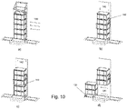
- a second gripper instead of a second gripper, provision can be made to provide a movable storage area in the vicinity of the gripper ( Figures 9 - 11 ).
- a movable part 152 of the storage area for example a movable storage or a (displaceable/displaceable) conveyor belt, can be fed to the gripper 142, whereby the gripper picks up boxes can transfer to the storage area (e.g. deposit on this - cf. Figure 11b ).
- the movable tray can then be moved away from the gripper (below the gripper) ( 11c ⁇ 11d), whereby a loading area (below) the gripper, i.e. an area, is released ( Figure 11d ), in which a transport device 130 can be provided so that the gripper can take over or hand over its boxes,
- the gripper for example, to first take over one or more boxes of a transport device ( Figure 10b ⁇ 11c), then transfers this to the storage area ( Figure 11a ⁇ 11b ⁇ 11c) and is therefore released for the inclusion of further boxes. If there is an empty transport device next to/near the movable storage area and/or in the loading area of the gripper, the movable storage area can transfer the intermediately stored boxes (subset) to the transport device again. Alternatively, the storage area can transfer the boxes back to the gripper 142 at a given time, which makes it possible overall to rearrange the boxes of one or more transport devices.
- the transport device can then be removed with the subset of boxes for further processing, or the additional boxes, which are picked up by the gripper, can be loaded onto the subset.
- boxes/a stack can be sorted on a transport device by means of either at least two grippers or at least one gripper in combination with the mobile storage area described above.
- the present invention relates to a corresponding device and a corresponding method.
- a possible rearrangement using the embodiment according to figure 11 could for example be done like this:
- a first transport device 130 is moved into an area below a first of the two grippers 142 shown.
- This first gripper 142 accepts any number of boxes from the transport device 130.
- the first gripper 142 then transfers the boxes or a subset of boxes to the movable part 152 of the storage area, which can be delivered to this first gripper for this purpose.
- the second gripper 142 can now either take over the boxes from the storage area, which is then delivered to the second gripper 142, or the gripper is already loaded with boxes, which the gripper places on the stack of boxes in the storage area can deposit as far as the storage area is delivered to the gripper.
- the gripper can then in turn lift all of the boxes or a subset of the merged boxes and, after the storage area has been withdrawn from the loading area of the second gripper (along with the remaining boxes, if applicable), transfer the held boxes of the second gripper to a transport device 130, which is positioned in the loading area of the second gripper 142.
Landscapes
- Engineering & Computer Science (AREA)
- Mechanical Engineering (AREA)
- Warehouses Or Storage Devices (AREA)
- Stacking Of Articles And Auxiliary Devices (AREA)
Abstract
System zum Speichern und Organisieren von Materialien, umfassend:ein Speichersystem (110),mindestens eine erste Schicht (100), die mehrere Lagerplätze umfasst, die bevorzugt in Reihen in zwei horizontalen Richtungen senkrecht zueinander angeordnet sind und dazu dienen, Boxen als Lagerplatz für die Materialien in Stapeln aufzunehmen,mindestens eine Transportvorrichtung (130), welche einen Aufnahmebereich für einzelne Boxen oder Stapel von Boxen zum oder aus dem Speichersystem aufweist,ein Transportsystem, insbesondere eine Schienenanordnung, auf welchem die mindestens eine Transportvorrichtung (130) vom, zum und innerhalb des Speichersystems verfahrbar und individuellen Stapeln von Boxen in dem Speichersystem (110) zustellbar gelagert ist undeine Sortiervorrichtung (140) mit- mindestens einem Greifer (142), welche über das Transportsystem mit dem Speichersystem verbunden und ausgebildet ist, eine Untermenge von Boxen oder alle Boxen eines Stapels von Boxen von der Transportvorrichtung aufzunehmen, anzuheben und an die Transportvorrichtung oder eine weitere Transportvorrichtung (130) wieder abzugeben und- mindestens einem zweiten Greifer (142), welchem die Transportvorrichtung in einem Ladebereich des Greifers zustellbar ist und ausgebildet ist, eine Untermenge der verbleibenden Boxen oder alle verbleibenden Boxen des Stapels von der Transportvorrichtung (130) aufzunehmen, oder- einem beweglichen Ablagebereich (152), welcher dem Greifer bzw. einem Ladebereich des Greifers zustellbar ist, von einer Transportvorrichtung aufgenommene Boxen von dem Greifer zu übernehmen und aus dem Ladebereich des Greifers in einen Ablagebereich zur Zwischenlagerung zu verschieben, wodurch der Ladebereich des Greifers für eine Aufnahme oder Abgabe von Boxen an/von einer Transportvorrichtung freigegeben ist, während die aufgenommenen Boxen in dem Ablagebereich zwischengelagert sind.A system for storing and organizing materials, comprising: a storage system (110), at least a first layer (100) comprising a plurality of storage bins, preferably arranged in rows in two horizontal directions perpendicular to each other and serving to form boxes as storage bins for the receiving materials in stacks, at least one transport device (130) which has a receiving area for individual boxes or stacks of boxes to or from the storage system, a transport system, in particular a rail arrangement, on which the at least one transport device (130) moves from, to and within of the storage system so that it can be moved and delivered to individual stacks of boxes in the storage system (110), and a sorting device (140) with at least one gripper (142), which is connected to the storage system via the transport system and is designed to be a subset of boxes or all of the boxes a stack of boxes from the transport device a picking up, lifting and re-delivering to the transport device or another transport device (130) and- at least one second gripper (142) to which the transport device can be delivered in a loading area of the gripper and is designed to hold a subset of the remaining boxes or all remaining boxes of the stack from the transport device (130), or- a movable storage area (152), which can be fed to the gripper or a loading area of the gripper, to take boxes picked up by a transport device from the gripper and move them from the loading area of the gripper to a storage area To move interim storage, whereby the loading area of the gripper for receiving or delivering boxes to / from a transport device is released, while the recorded boxes are temporarily stored in the storage area.
Description
Die vorliegende Erfindung betrifft eine Sortiervorrichtung gemäß Anspruch 1.The present invention relates to a sorting device according to claim 1.
Zum besseren Verständnis des Wesens der vorgeschlagenen technischen Lösung folgt nachstehend die Beschreibung eines spezifischen Implementierungsbeispiels, das kein einschränkendes Beispiel für die praktische Implementierung eines automatischen Systems zum Speichern von Materialien und Sammeln von Sätzen davon ist.For a better understanding of the essence of the proposed technical solution, below follows the description of a specific example of implementation, which is not a limiting example of the practical implementation of an automatic system for storing materials and collecting batches thereof.
Die beanspruchte Erfindung wird anhand der beigefügten Zeichnungen näher erläutert. Es zeigen:
- Fig. 1
- ein allgemeines Diagramm eines automatischen Systems,
- Fig. 2
- ein automatisches System, Vorderansicht, perspektivische Ansicht,
- Fig. 3
- ein schematisches Diagramm einer mobilen Transportvorrichtung,
- Fig. 4
- eine allgemeine Ansicht eines mobilen Transportgeräts,
- Fig. 5
- ein mobiles Transportgerät mit einem Stapel von Schalen an Bord,
- Fig. 6
- ein schematisches Diagramm einer Vorrichtung zum Heben von Stapeln von Schalen,
- Fig. 7
- eine Vorrichtung zum Anheben von Stapeln von Schalen, allgemeine Ansicht,
- Fig. 8
- eine Vorrichtung zum Anheben von Stapeln von Tabletts, die mit Stapeln von Tabletts interagieren, und eine mobile Transportvorrichtung,
- Fig. 9 - 11
- eine alternative Ausführungsform mit einem Greifer und einem beweglichen Ablagebereich, welche den zweiten Greifer ersetzen kann mit vorteilhaftem Bewegungsablauf und
- Fig. 12
- eine Kombination der ersten und zweiten Ausführungsform, also mit mindestens einem weiteren Greifer und mindestens einem beweglichen Ablagebereich.
- 1
- a general diagram of an automatic system,
- 2
- an automatic system, front view, perspective view,
- 3
- a schematic diagram of a mobile transport device,
- 4
- a general view of a mobile transport device,
- figure 5
- a mobile transport device with a stack of shells on board,
- 6
- a schematic diagram of a device for lifting stacks of trays,
- 7
- a device for lifting stacks of trays, general view,
- 8
- a device for lifting stacks of trays interacting with stacks of trays and a mobile transport device,
- Figures 9 - 11
- an alternative embodiment with a gripper and a movable storage area, which can replace the second gripper with an advantageous movement sequence and
- 12
- a combination of the first and second embodiment, ie with at least one additional gripper and at least one movable storage area.
Wie in den
Mehrere mobile Transportvorrichtungen 130 können über eine drahtlose Schnittstelle 54 von einem Zentralprozessor 50 gesteuert werden und/oder sind bereitgestellt, sowohl leere also auch volle Boxen/Schalen als auch gestapelte Boxen/Schalen 101 (
Wie in
Die Schalen innerhalb des Speichersystems 110 sind in Stapeln von vorzugsweise n Schalen übereinander gelagert, in einem speziellen Fall ist n >= 5, wie in den Figuren dargestellt.The shells within the
Wie in
Die in
Der konstruktive Aufbau der TMU 130 bzw. der Lagereinrichtung 110 ist derart hergestellt, dass eine leere Vorrichtung 130 mit seinem Hubtisch 131 ohne darauf befindliche/transportierte Schalen/Box im Speicherbereich 110 jeweils unterhalb der Stapel hindurch frei beweglich verfahrbar ist. Dadurch kann die TMU auch Stapeln zugestellt werden, die sich in weiter hinten liegenden Bereichen des Speicherbereichs befinden, ohne einen Umweg um den Speicherbereich selbst herum fahren zu müssen.The structural design of the TMU 130 or the
Die mobile Transportvorrichtung 130, welche bevorzugt Teil des erfindungsgemäßen Lagers und Sortiersystems ist, kann auf jede bekannte Weise gesteuert werden. Insbesondere kann eine eingebettete (industrielle) Steuerung 134 mit einer drahtlosen Schnittstelle 135 zur Kommunikation mit dem Zentralprozessor 51 des automatischen Systems zur Steuerung verwendet werden. Die Steuerung 134 steuert die Treiber 136 der Antriebe der Räder 132 und 133 für die Bewegung, bevorzugt entlang von Schienen, in vorzugsweise zwei Richtungen in einer Ebene und/oder den Treiber 137 der vertikalen Position der Räder 132, 133, über welchen die Räder angehoben werden können und dadurch die Unterseite des Hubtisches den Boden berühren kann und/oder den Zustand des Hubtisches 131 (Höhenverstellbarkeit). Die Schienen können in dem Speicherbereich 110 und/oder im Sortierbereich, also auch zwischen den Bereichen, verbindend vorliegen und können als Grundlage für die Bewegung der Transportvorrichtungen 130 bereitgestellt sein.The
In den
Die Vorrichtung zum Heben von Stapeln von Schalen 140 kann auch auf irgendeine bekannte Weise gesteuert werden. Insbesondere kann eine eingebettete industrielle Steuerung 143 verwendet werden, die eine Schnittstelle 144 zur Kommunikation mit dem Zentralprozessor 51 des automatischen Systems 100 aufweist. Bevorzugt steuert die Steuerung 143 die Treiber 145 und 146 der jeweiligen Greiferantriebe 142 zum Aufnehmen und Anheben der (Stapel von) Schale(n)/ Box(en) 101 in vertikaler Richtung.The device for lifting stacks of
Danach bewegt sich die TMU 130 in einer ersten horizontalen Richtung unter den zweiten (linken) Greifer 142 der Vorrichtung 140. Dann hebt der zweite Greifer 142 die (verbleibende) Schale/Box 101 von der TMU 130 an.Thereafter, the
Anschließend bewegt sich die TMU unter dem ersten Greifer 142 der Vorrichtung 140, wodurch der zuerst abgehobene Stapel der Schalen/Boxen 101 auf die TMU 130 gelegt wird. Danach bewegt sich die TMU 130 wieder unter dem zweiten (entsprechend angehobenen) Greifer 142 der Vorrichtung 140, die die zuvor untere Schale/Box 101 des Stapels nun oben auf dem Stapel platziert. Nach der vorliegenden Erfindung kann es sich bei den beschriebenen und beanspruchten "Systemen" um Vorrichtungen und Einrichtungen handeln.The TMU then moves under the
Alternativ oder ergänzend kann es vorgesehen sein, anstatt einem zweiten Greifer zusätzlich zu diesem einen beweglichen Ablagebereich in der Nähe des Greifers vorzusehen (
Dadurch ist es ermöglicht, dass der Greifer beispielsweise zunächst einen oder mehrere Boxen einer Transporteinrichtung übernimmt (
Grundsätzlich ist es auch denkbar, eine Kombination der ersten und der zweiten Ausführungsform vorzusehen, wie es beispielhaft aus
Eine mögliche Umsortierung mittels der Ausführungsform nach
Eine erste Transportvorrichtung 130 wird in einen Bereich unterhalb eines ersten der beiden dargestellten Greifer 142 verfahren. Dieser erste Greifer 142 übernimmt eine beliebige Anzahl von Boxen von der Transportvorrichtung 130. Anschließend übergibt der erste Greifer 142 die Boxen oder eine Untermenge von Boxen an den beweglichen Teil 152 des Ablagebereichs, welcher dafür diesem ersten Greifer zustellbar ist.A possible rearrangement using the embodiment according to
A
Auf der anderen Seite, bei dem zweiten Greifer 142, kann dieser nun entweder die Boxen von dem Ablagebereich übernehmen, welcher dafür dem zweiten Greifer 142 zugestellt wird, oder der Greifer ist bereits mit Boxen beladen, welche der Greifer auf den Stapel von Boxen des Ablagebereichs ablegen kann, soweit der Ablagebereich dem Greifer zugestellt ist. Anschließend kann der Greifer wiederum alle Boxen oder eine Untermenge der zusammengeführten Boxen anheben und, nachdem der Ablagebereich aus dem Ladebereich des zweiten Greifers (zusammen mit den restlichen Boxen, soweit zutreffend) zurückgezogen ist, die gehaltenen Boxen des zweiten Greifers auf eine Transporteinrichtung 130 übergeben, welche in dem Ladebereich des zweiten Greifers 142 positioniert wird.On the other hand, the
So kann ein Umschichten zwischen verschiedenen Transportvorrichtungen 130 und/oder eine Änderung der Reihenfolge von Boxen einer Transportvorrichtung 130 ermöglicht werden.In this way, a rearrangement between
Claims (8)
dadurch gekennzeichnet,
dass der Greifer höhenverstellbar ist und ausgebildet ist, Boxen von einer Transportvorrichtung (130) anzuheben.System for storing and organizing materials according to claim 1,
characterized,
that the gripper is adjustable in height and is designed to lift boxes from a transport device (130).
dadurch gekennzeichnet,
dass der bewegliche Ablagebereich (152) als verlagerbare Fläche oder als Förderband ausgebildet ist, die dem Ladebereich des Greifers zustellbar ist.System for storing and organizing materials according to claim 1 or 2,
characterized,
that the movable storage area (152) is designed as a displaceable surface or as a conveyor belt that can be delivered to the loading area of the gripper.
dadurch gekennzeichnet,
dass das Transportsystem bereichsweise unterhalb der Greifer (142) angeordnet ist und dort den Ladebereich für den oder die Greifer (142) bildet.System for storing and organizing materials according to any one of claims 1 to 3,
characterized,
that the transport system is arranged in some areas underneath the grippers (142) and there forms the loading area for the gripper or grippers (142).
dadurch gekennzeichnet,
dass der bewegliche Ablagebereich (152) dem jeweiligen Ladebereich einer Mehrzahl von Greifern (142) zustellbar ist.System for storing and organizing materials according to claim 1 or 2,
characterized,
that the movable storage area (152) can be delivered to the respective loading area of a plurality of grippers (142).
dadurch gekennzeichnet,
dass sowohl ein zweiter Greifer (142) als auch eine Lagereinrichtung (150) vorgesehen sind, wobei die Lagereinrichtung (150) zwischen den Lagerbereichen der beiden Greifer angeordnet ist, der bewegliche Lagerbereich (152) der Lagereinrichtung (150) dem jeweiligen Ladebereich beider Greifer (142) zustellbar ist und ausgebildet ist, auf dem beweglichen Lagerbereich vorgesehene Boxen an den jeweiligen Greifer zu übergeben bzw. Boxen von den Greifern zu übernehmen.Sorting device according to claim 6,
characterized,
that both a second gripper (142) and a storage device (150) are provided, with the storage device (150) being arranged between the storage areas of the two grippers, the movable storage area (152) of the storage device (150) being arranged in the respective loading area of both grippers ( 142) can be delivered and is designed to transfer boxes provided on the movable storage area to the respective gripper or to accept boxes from the grippers.
bei welchem die Materialien in Boxen (101) eingelagert und die Boxen (101) in Stapeln organisiert sind,
wobei die Stapel von Boxen mittels mindestens einer Transportvorrichtung (130) zwischen einem Speichersystem (110) für die Stapel und einer Sortiervorrichtung (140) für die Boxen (101) eines Stapels transportierbar sind, wobei zumindest ein Teil der transportierten Boxen (101) des einen Stapels von Boxen (101) in einem Ladebereich der Sortiervorrichtung (140) übernommen wird,
wobei die Sortiervorrichtung mindestens einen ersten Greifer (142) aufweist, welcher den zu übernehmenden Teil der Boxen (101) aus dem Stapel aufnimmt und hält,
wobei die aufgenommenen Boxen (101) mittels des mindestens einen ersten Greifers (142) angehoben werden, so dass die Transportvorrichtung (130) ohne den angehobenen Teil der Boxen (101) aus dem Ladebereich des Greifers (142) verfahrbar ist,
wobei
in which the materials are stored in boxes (101) and the boxes (101) are organized in stacks,
wherein the stacks of boxes can be transported by means of at least one transport device (130) between a storage system (110) for the stacks and a sorting device (140) for the boxes (101) of a stack, with at least some of the transported boxes (101) of one Stack of boxes (101) is taken over in a loading area of the sorting device (140),
wherein the sorting device has at least one first gripper (142) which picks up and holds the part of the boxes (101) to be taken over from the stack,
wherein the picked-up boxes (101) are lifted by means of the at least one first gripper (142), so that the transport device (130) can be moved out of the loading area of the gripper (142) without the lifted part of the boxes (101),
whereby
Priority Applications (6)
| Application Number | Priority Date | Filing Date | Title |
|---|---|---|---|
| EP21166762.1A EP4067264A1 (en) | 2021-04-01 | 2021-04-01 | Sorting device |
| CN202280032473.2A CN117242019A (en) | 2021-04-01 | 2022-04-01 | Sorting device |
| CA3213070A CA3213070A1 (en) | 2021-04-01 | 2022-04-01 | Sorting device |
| JP2023560370A JP2024511849A (en) | 2021-04-01 | 2022-04-01 | sorting equipment |
| EP22720394.0A EP4121373A1 (en) | 2021-04-01 | 2022-04-01 | Sorting device |
| PCT/EP2022/058762 WO2022207911A1 (en) | 2021-04-01 | 2022-04-01 | Sorting device |
Applications Claiming Priority (1)
| Application Number | Priority Date | Filing Date | Title |
|---|---|---|---|
| EP21166762.1A EP4067264A1 (en) | 2021-04-01 | 2021-04-01 | Sorting device |
Publications (1)
| Publication Number | Publication Date |
|---|---|
| EP4067264A1 true EP4067264A1 (en) | 2022-10-05 |
Family
ID=75362531
Family Applications (2)
| Application Number | Title | Priority Date | Filing Date |
|---|---|---|---|
| EP21166762.1A Withdrawn EP4067264A1 (en) | 2021-04-01 | 2021-04-01 | Sorting device |
| EP22720394.0A Pending EP4121373A1 (en) | 2021-04-01 | 2022-04-01 | Sorting device |
Family Applications After (1)
| Application Number | Title | Priority Date | Filing Date |
|---|---|---|---|
| EP22720394.0A Pending EP4121373A1 (en) | 2021-04-01 | 2022-04-01 | Sorting device |
Country Status (5)
| Country | Link |
|---|---|
| EP (2) | EP4067264A1 (en) |
| JP (1) | JP2024511849A (en) |
| CN (1) | CN117242019A (en) |
| CA (1) | CA3213070A1 (en) |
| WO (1) | WO2022207911A1 (en) |
Citations (5)
| Publication number | Priority date | Publication date | Assignee | Title |
|---|---|---|---|---|
| DE2015881A1 (en) * | 1970-04-03 | 1971-10-14 | Bollmann, Ludwig, 7703 Rielasingen | Process and equipment for the internal transport of bulky heavy loads |
| JPH08244973A (en) * | 1995-03-07 | 1996-09-24 | Nkk Corp | Tiering and assorting device for container |
| DE29911966U1 (en) * | 1999-07-08 | 1999-10-14 | Mds Maschinen Und Werkzeugbau | Device for stacking pallets or the like. container |
| WO2014189388A1 (en) * | 2013-05-21 | 2014-11-27 | Sodium Limited | System and method for creating a structured set of containers |
| WO2018090081A1 (en) * | 2016-11-15 | 2018-05-24 | Swisslog Australia Pty Limited | A system for, and a method of, order palletising |
-
2021
- 2021-04-01 EP EP21166762.1A patent/EP4067264A1/en not_active Withdrawn
-
2022
- 2022-04-01 JP JP2023560370A patent/JP2024511849A/en active Pending
- 2022-04-01 CN CN202280032473.2A patent/CN117242019A/en active Pending
- 2022-04-01 CA CA3213070A patent/CA3213070A1/en active Pending
- 2022-04-01 WO PCT/EP2022/058762 patent/WO2022207911A1/en active Application Filing
- 2022-04-01 EP EP22720394.0A patent/EP4121373A1/en active Pending
Patent Citations (5)
| Publication number | Priority date | Publication date | Assignee | Title |
|---|---|---|---|---|
| DE2015881A1 (en) * | 1970-04-03 | 1971-10-14 | Bollmann, Ludwig, 7703 Rielasingen | Process and equipment for the internal transport of bulky heavy loads |
| JPH08244973A (en) * | 1995-03-07 | 1996-09-24 | Nkk Corp | Tiering and assorting device for container |
| DE29911966U1 (en) * | 1999-07-08 | 1999-10-14 | Mds Maschinen Und Werkzeugbau | Device for stacking pallets or the like. container |
| WO2014189388A1 (en) * | 2013-05-21 | 2014-11-27 | Sodium Limited | System and method for creating a structured set of containers |
| WO2018090081A1 (en) * | 2016-11-15 | 2018-05-24 | Swisslog Australia Pty Limited | A system for, and a method of, order palletising |
Also Published As
| Publication number | Publication date |
|---|---|
| CN117242019A (en) | 2023-12-15 |
| WO2022207911A1 (en) | 2022-10-06 |
| CA3213070A1 (en) | 2022-10-06 |
| JP2024511849A (en) | 2024-03-15 |
| EP4121373A1 (en) | 2023-01-25 |
Similar Documents
| Publication | Publication Date | Title |
|---|---|---|
| EP2287093B2 (en) | Racking system and method for operating same | |
| DE102008046325A1 (en) | Method and device for the unmanned, fully automated picking of articles in order loading equipment | |
| DE102013216823A1 (en) | Storage device for stackable containers | |
| EP1136394A2 (en) | Device for order picking | |
| EP2753558B1 (en) | Order-picking station and method for order-picking of articles from a loading aid | |
| DE19849391A1 (en) | Storage facility for stacking crates, sending device of which has at least one transporting device able to travel under stored crates | |
| EP3741517A1 (en) | Method for transferring products and transfer robot for same | |
| DE102018215780A1 (en) | Device and method for handling storage units | |
| EP1762511A1 (en) | Automatic warehouse comprising an operating device with a buffer shaft | |
| DE102019115634B3 (en) | Sorting system for a machine tool, machine tool and method for sorting cut parts | |
| EP0986508B1 (en) | Commissioning system with a high-speed automatic machine and a shelf control unit | |
| DE202020104955U1 (en) | Elevator and shelving system | |
| EP2143667B1 (en) | Storage device for bulk goods and corresponding method | |
| EP4067264A1 (en) | Sorting device | |
| EP3889076B1 (en) | Picking system and picking method | |
| DE102021108457A1 (en) | sorting device | |
| DE102018113894A1 (en) | Method and device for automatic multi-layer stacking of a carrier with packages | |
| DE102009014636B4 (en) | Picking cut flowers and / or plants with a robot | |
| DE102020126248A1 (en) | Mobile transport vehicle | |
| WO2023227801A1 (en) | Sorting device | |
| EP1862405B1 (en) | Method for gripping piece goods using gripper devices of an input and output system and device therefor | |
| EP1524209B1 (en) | Method and device for simultaneously retrieving a plurality of articles in a shelf storage | |
| EP0416627A1 (en) | Method and device for storing goods and automatically selecting them from shelves in large scale stores | |
| DE102005031923A1 (en) | Method and device for loading and unloading elements into a carrier element | |
| EP0786635A2 (en) | Installation for charging and discharging ceramic articles from the superstructures of a firing bench |
Legal Events
| Date | Code | Title | Description |
|---|---|---|---|
| PUAI | Public reference made under article 153(3) epc to a published international application that has entered the european phase |
Free format text: ORIGINAL CODE: 0009012 |
|
| STAA | Information on the status of an ep patent application or granted ep patent |
Free format text: STATUS: THE APPLICATION HAS BEEN PUBLISHED |
|
| AK | Designated contracting states |
Kind code of ref document: A1 Designated state(s): AL AT BE BG CH CY CZ DE DK EE ES FI FR GB GR HR HU IE IS IT LI LT LU LV MC MK MT NL NO PL PT RO RS SE SI SK SM TR |
|
| STAA | Information on the status of an ep patent application or granted ep patent |
Free format text: STATUS: THE APPLICATION HAS BEEN WITHDRAWN |
|
| 18W | Application withdrawn |
Effective date: 20221107 |