EP4056898A1 - Biomass heating system with a control device optimized by means of machine learning and corresponding method - Google Patents
Biomass heating system with a control device optimized by means of machine learning and corresponding method Download PDFInfo
- Publication number
- EP4056898A1 EP4056898A1 EP21218435.2A EP21218435A EP4056898A1 EP 4056898 A1 EP4056898 A1 EP 4056898A1 EP 21218435 A EP21218435 A EP 21218435A EP 4056898 A1 EP4056898 A1 EP 4056898A1
- Authority
- EP
- European Patent Office
- Prior art keywords
- heating system
- biomass heating
- combustion chamber
- sensor
- model
- Prior art date
- Legal status (The legal status is an assumption and is not a legal conclusion. Google has not performed a legal analysis and makes no representation as to the accuracy of the status listed.)
- Granted
Links
- 238000010438 heat treatment Methods 0.000 title claims abstract description 396
- 239000002028 Biomass Substances 0.000 title claims abstract description 389
- 238000010801 machine learning Methods 0.000 title claims abstract description 110
- 238000000034 method Methods 0.000 title claims description 107
- 238000002485 combustion reaction Methods 0.000 claims abstract description 445
- 239000000446 fuel Substances 0.000 claims abstract description 254
- 230000015654 memory Effects 0.000 claims abstract description 45
- 239000000126 substance Substances 0.000 claims abstract description 38
- 230000000035 biogenic effect Effects 0.000 claims abstract description 8
- 239000007789 gas Substances 0.000 claims description 102
- 238000012545 processing Methods 0.000 claims description 51
- 238000013528 artificial neural network Methods 0.000 claims description 47
- 239000008188 pellet Substances 0.000 claims description 44
- 239000002023 wood Substances 0.000 claims description 44
- QVGXLLKOCUKJST-UHFFFAOYSA-N atomic oxygen Chemical compound [O] QVGXLLKOCUKJST-UHFFFAOYSA-N 0.000 claims description 36
- 239000001301 oxygen Substances 0.000 claims description 36
- 229910052760 oxygen Inorganic materials 0.000 claims description 36
- 230000008569 process Effects 0.000 claims description 31
- 239000000523 sample Substances 0.000 claims description 31
- 238000004422 calculation algorithm Methods 0.000 claims description 27
- 210000002569 neuron Anatomy 0.000 claims description 25
- 230000033228 biological regulation Effects 0.000 claims description 24
- 238000001514 detection method Methods 0.000 claims description 21
- 238000004364 calculation method Methods 0.000 claims description 18
- 230000005540 biological transmission Effects 0.000 claims description 14
- 238000003860 storage Methods 0.000 claims description 10
- 238000010304 firing Methods 0.000 claims description 9
- 239000004449 solid propellant Substances 0.000 claims description 8
- 230000004931 aggregating effect Effects 0.000 claims description 5
- 239000000872 buffer Substances 0.000 claims description 4
- 239000003570 air Substances 0.000 description 231
- 238000013473 artificial intelligence Methods 0.000 description 156
- UGFAIRIUMAVXCW-UHFFFAOYSA-N Carbon monoxide Chemical compound [O+]#[C-] UGFAIRIUMAVXCW-UHFFFAOYSA-N 0.000 description 98
- 239000003546 flue gas Substances 0.000 description 98
- 238000002156 mixing Methods 0.000 description 93
- 238000012549 training Methods 0.000 description 49
- 239000011449 brick Substances 0.000 description 38
- XLYOFNOQVPJJNP-UHFFFAOYSA-N water Substances O XLYOFNOQVPJJNP-UHFFFAOYSA-N 0.000 description 35
- 239000002956 ash Substances 0.000 description 32
- 239000000203 mixture Substances 0.000 description 27
- 238000004140 cleaning Methods 0.000 description 26
- 230000006870 function Effects 0.000 description 22
- 239000002893 slag Substances 0.000 description 20
- 238000010586 diagram Methods 0.000 description 19
- 238000013459 approach Methods 0.000 description 17
- 238000012423 maintenance Methods 0.000 description 17
- 230000007246 mechanism Effects 0.000 description 17
- 238000004088 simulation Methods 0.000 description 16
- 230000015572 biosynthetic process Effects 0.000 description 15
- 230000001276 controlling effect Effects 0.000 description 15
- 230000008859 change Effects 0.000 description 14
- 230000001105 regulatory effect Effects 0.000 description 14
- 238000013461 design Methods 0.000 description 13
- CURLTUGMZLYLDI-UHFFFAOYSA-N Carbon dioxide Chemical compound O=C=O CURLTUGMZLYLDI-UHFFFAOYSA-N 0.000 description 12
- 230000006399 behavior Effects 0.000 description 12
- 238000009826 distribution Methods 0.000 description 12
- 238000000197 pyrolysis Methods 0.000 description 12
- 239000013598 vector Substances 0.000 description 12
- 238000001914 filtration Methods 0.000 description 11
- 239000008236 heating water Substances 0.000 description 11
- 239000000428 dust Substances 0.000 description 10
- 239000000463 material Substances 0.000 description 10
- 238000005259 measurement Methods 0.000 description 10
- 238000011161 development Methods 0.000 description 9
- 230000018109 developmental process Effects 0.000 description 9
- 230000036961 partial effect Effects 0.000 description 9
- 230000009467 reduction Effects 0.000 description 9
- 238000012360 testing method Methods 0.000 description 9
- 230000007704 transition Effects 0.000 description 9
- 230000000694 effects Effects 0.000 description 8
- 238000012546 transfer Methods 0.000 description 8
- 238000006243 chemical reaction Methods 0.000 description 7
- 230000001419 dependent effect Effects 0.000 description 7
- 239000012717 electrostatic precipitator Substances 0.000 description 7
- 238000005516 engineering process Methods 0.000 description 7
- 238000005457 optimization Methods 0.000 description 7
- 239000002245 particle Substances 0.000 description 7
- 230000002829 reductive effect Effects 0.000 description 7
- 239000012080 ambient air Substances 0.000 description 6
- 230000008901 benefit Effects 0.000 description 6
- 239000001569 carbon dioxide Substances 0.000 description 6
- 229910002092 carbon dioxide Inorganic materials 0.000 description 6
- 238000004891 communication Methods 0.000 description 6
- 238000004590 computer program Methods 0.000 description 6
- 239000012530 fluid Substances 0.000 description 6
- 241000196324 Embryophyta Species 0.000 description 5
- 238000013135 deep learning Methods 0.000 description 5
- 238000002474 experimental method Methods 0.000 description 5
- 238000002309 gasification Methods 0.000 description 5
- 230000003993 interaction Effects 0.000 description 5
- 238000004519 manufacturing process Methods 0.000 description 5
- 230000003647 oxidation Effects 0.000 description 5
- 238000007254 oxidation reaction Methods 0.000 description 5
- 239000000047 product Substances 0.000 description 5
- 239000007787 solid Substances 0.000 description 5
- OKTJSMMVPCPJKN-UHFFFAOYSA-N Carbon Chemical compound [C] OKTJSMMVPCPJKN-UHFFFAOYSA-N 0.000 description 4
- 241000237858 Gastropoda Species 0.000 description 4
- 235000015696 Portulacaria afra Nutrition 0.000 description 4
- 235000018747 Typha elephantina Nutrition 0.000 description 4
- 244000177175 Typha elephantina Species 0.000 description 4
- 229910052799 carbon Inorganic materials 0.000 description 4
- 238000001816 cooling Methods 0.000 description 4
- 230000007423 decrease Effects 0.000 description 4
- 238000002347 injection Methods 0.000 description 4
- 239000007924 injection Substances 0.000 description 4
- 238000009413 insulation Methods 0.000 description 4
- 238000002844 melting Methods 0.000 description 4
- 230000008018 melting Effects 0.000 description 4
- 239000007921 spray Substances 0.000 description 4
- 238000009825 accumulation Methods 0.000 description 3
- 230000004913 activation Effects 0.000 description 3
- 210000004027 cell Anatomy 0.000 description 3
- 239000003610 charcoal Substances 0.000 description 3
- 238000013145 classification model Methods 0.000 description 3
- 230000000295 complement effect Effects 0.000 description 3
- 238000005520 cutting process Methods 0.000 description 3
- 238000001035 drying Methods 0.000 description 3
- 238000011156 evaluation Methods 0.000 description 3
- 238000012986 modification Methods 0.000 description 3
- 230000004048 modification Effects 0.000 description 3
- 230000004044 response Effects 0.000 description 3
- 238000000926 separation method Methods 0.000 description 3
- 239000000243 solution Substances 0.000 description 3
- 238000011144 upstream manufacturing Methods 0.000 description 3
- 229910052902 vermiculite Inorganic materials 0.000 description 3
- 239000010455 vermiculite Substances 0.000 description 3
- 235000019354 vermiculite Nutrition 0.000 description 3
- 240000007817 Olea europaea Species 0.000 description 2
- 229910000831 Steel Inorganic materials 0.000 description 2
- 230000006978 adaptation Effects 0.000 description 2
- 238000007792 addition Methods 0.000 description 2
- 238000004458 analytical method Methods 0.000 description 2
- 230000001413 cellular effect Effects 0.000 description 2
- 238000000354 decomposition reaction Methods 0.000 description 2
- 230000003111 delayed effect Effects 0.000 description 2
- 239000003344 environmental pollutant Substances 0.000 description 2
- 239000010881 fly ash Substances 0.000 description 2
- 230000014509 gene expression Effects 0.000 description 2
- 239000008240 homogeneous mixture Substances 0.000 description 2
- 238000000265 homogenisation Methods 0.000 description 2
- 230000006872 improvement Effects 0.000 description 2
- 239000012535 impurity Substances 0.000 description 2
- 238000003780 insertion Methods 0.000 description 2
- 230000037431 insertion Effects 0.000 description 2
- 238000009434 installation Methods 0.000 description 2
- JEIPFZHSYJVQDO-UHFFFAOYSA-N iron(III) oxide Inorganic materials O=[Fe]O[Fe]=O JEIPFZHSYJVQDO-UHFFFAOYSA-N 0.000 description 2
- 230000007257 malfunction Effects 0.000 description 2
- 239000011159 matrix material Substances 0.000 description 2
- 229910052751 metal Inorganic materials 0.000 description 2
- 239000002184 metal Substances 0.000 description 2
- 238000011017 operating method Methods 0.000 description 2
- 231100000719 pollutant Toxicity 0.000 description 2
- 238000007639 printing Methods 0.000 description 2
- 230000005855 radiation Effects 0.000 description 2
- 230000003134 recirculating effect Effects 0.000 description 2
- 230000002787 reinforcement Effects 0.000 description 2
- 230000000717 retained effect Effects 0.000 description 2
- 230000000630 rising effect Effects 0.000 description 2
- 238000013515 script Methods 0.000 description 2
- 230000001953 sensory effect Effects 0.000 description 2
- 238000005245 sintering Methods 0.000 description 2
- 230000006641 stabilisation Effects 0.000 description 2
- 238000011105 stabilization Methods 0.000 description 2
- 239000010959 steel Substances 0.000 description 2
- 241001136792 Alle Species 0.000 description 1
- 229910001018 Cast iron Inorganic materials 0.000 description 1
- UFHFLCQGNIYNRP-UHFFFAOYSA-N Hydrogen Chemical compound [H][H] UFHFLCQGNIYNRP-UHFFFAOYSA-N 0.000 description 1
- 240000003433 Miscanthus floridulus Species 0.000 description 1
- 108091028043 Nucleic acid sequence Proteins 0.000 description 1
- 244000081757 Phalaris arundinacea Species 0.000 description 1
- 235000014676 Phragmites communis Nutrition 0.000 description 1
- 241000218657 Picea Species 0.000 description 1
- 241000009334 Singa Species 0.000 description 1
- 229910000639 Spring steel Inorganic materials 0.000 description 1
- 241001441724 Tetraodontidae Species 0.000 description 1
- 238000005299 abrasion Methods 0.000 description 1
- 230000009471 action Effects 0.000 description 1
- 230000003044 adaptive effect Effects 0.000 description 1
- 230000002457 bidirectional effect Effects 0.000 description 1
- 210000004556 brain Anatomy 0.000 description 1
- 229910002091 carbon monoxide Inorganic materials 0.000 description 1
- 239000000919 ceramic Substances 0.000 description 1
- 238000001311 chemical methods and process Methods 0.000 description 1
- 239000007795 chemical reaction product Substances 0.000 description 1
- 239000003795 chemical substances by application Substances 0.000 description 1
- 230000003749 cleanliness Effects 0.000 description 1
- 230000003930 cognitive ability Effects 0.000 description 1
- 230000001149 cognitive effect Effects 0.000 description 1
- 239000000571 coke Substances 0.000 description 1
- 239000000567 combustion gas Substances 0.000 description 1
- 150000001875 compounds Chemical class 0.000 description 1
- 238000010276 construction Methods 0.000 description 1
- 238000011217 control strategy Methods 0.000 description 1
- 238000013480 data collection Methods 0.000 description 1
- 238000002405 diagnostic procedure Methods 0.000 description 1
- 230000005684 electric field Effects 0.000 description 1
- 230000005611 electricity Effects 0.000 description 1
- 230000003628 erosive effect Effects 0.000 description 1
- 239000000284 extract Substances 0.000 description 1
- 238000000605 extraction Methods 0.000 description 1
- 230000002349 favourable effect Effects 0.000 description 1
- 239000002828 fuel tank Substances 0.000 description 1
- 238000009499 grossing Methods 0.000 description 1
- 230000017525 heat dissipation Effects 0.000 description 1
- 229930195733 hydrocarbon Natural products 0.000 description 1
- 150000002430 hydrocarbons Chemical class 0.000 description 1
- 229910052739 hydrogen Inorganic materials 0.000 description 1
- 239000001257 hydrogen Substances 0.000 description 1
- 230000010365 information processing Effects 0.000 description 1
- 230000000977 initiatory effect Effects 0.000 description 1
- 229910052500 inorganic mineral Inorganic materials 0.000 description 1
- 239000011810 insulating material Substances 0.000 description 1
- 239000012774 insulation material Substances 0.000 description 1
- 239000012212 insulator Substances 0.000 description 1
- 230000001788 irregular Effects 0.000 description 1
- 238000002955 isolation Methods 0.000 description 1
- 238000012804 iterative process Methods 0.000 description 1
- 238000002372 labelling Methods 0.000 description 1
- 239000007788 liquid Substances 0.000 description 1
- 239000004973 liquid crystal related substance Substances 0.000 description 1
- 230000014759 maintenance of location Effects 0.000 description 1
- 238000013507 mapping Methods 0.000 description 1
- 238000013178 mathematical model Methods 0.000 description 1
- 230000013011 mating Effects 0.000 description 1
- 239000011707 mineral Substances 0.000 description 1
- 235000010755 mineral Nutrition 0.000 description 1
- 230000006855 networking Effects 0.000 description 1
- 230000001537 neural effect Effects 0.000 description 1
- 230000007935 neutral effect Effects 0.000 description 1
- 230000003287 optical effect Effects 0.000 description 1
- 230000002093 peripheral effect Effects 0.000 description 1
- 238000001556 precipitation Methods 0.000 description 1
- 238000002360 preparation method Methods 0.000 description 1
- 238000004321 preservation Methods 0.000 description 1
- 238000000513 principal component analysis Methods 0.000 description 1
- 230000004043 responsiveness Effects 0.000 description 1
- 238000007789 sealing Methods 0.000 description 1
- 239000003566 sealing material Substances 0.000 description 1
- 239000004065 semiconductor Substances 0.000 description 1
- 238000010008 shearing Methods 0.000 description 1
- HBMJWWWQQXIZIP-UHFFFAOYSA-N silicon carbide Chemical compound [Si+]#[C-] HBMJWWWQQXIZIP-UHFFFAOYSA-N 0.000 description 1
- 229910010271 silicon carbide Inorganic materials 0.000 description 1
- 239000007784 solid electrolyte Substances 0.000 description 1
- 239000004071 soot Substances 0.000 description 1
- 238000001228 spectrum Methods 0.000 description 1
- 229910001220 stainless steel Inorganic materials 0.000 description 1
- 230000003068 static effect Effects 0.000 description 1
- 238000013179 statistical model Methods 0.000 description 1
- 239000013589 supplement Substances 0.000 description 1
- 238000005496 tempering Methods 0.000 description 1
- 238000005979 thermal decomposition reaction Methods 0.000 description 1
- 239000011573 trace mineral Substances 0.000 description 1
- 235000013619 trace mineral Nutrition 0.000 description 1
- 238000013519 translation Methods 0.000 description 1
- 238000009827 uniform distribution Methods 0.000 description 1
- 238000012559 user support system Methods 0.000 description 1
- 238000010200 validation analysis Methods 0.000 description 1
- 230000000007 visual effect Effects 0.000 description 1
- 230000001755 vocal effect Effects 0.000 description 1
- 239000002912 waste gas Substances 0.000 description 1
- 239000002699 waste material Substances 0.000 description 1
Images


Classifications
-
- F—MECHANICAL ENGINEERING; LIGHTING; HEATING; WEAPONS; BLASTING
- F23—COMBUSTION APPARATUS; COMBUSTION PROCESSES
- F23H—GRATES; CLEANING OR RAKING GRATES
- F23H15/00—Cleaning arrangements for grates; Moving fuel along grates
-
- F—MECHANICAL ENGINEERING; LIGHTING; HEATING; WEAPONS; BLASTING
- F23—COMBUSTION APPARATUS; COMBUSTION PROCESSES
- F23G—CREMATION FURNACES; CONSUMING WASTE PRODUCTS BY COMBUSTION
- F23G5/00—Incineration of waste; Incinerator constructions; Details, accessories or control therefor
- F23G5/50—Control or safety arrangements
-
- F—MECHANICAL ENGINEERING; LIGHTING; HEATING; WEAPONS; BLASTING
- F23—COMBUSTION APPARATUS; COMBUSTION PROCESSES
- F23G—CREMATION FURNACES; CONSUMING WASTE PRODUCTS BY COMBUSTION
- F23G7/00—Incinerators or other apparatus for consuming industrial waste, e.g. chemicals
- F23G7/10—Incinerators or other apparatus for consuming industrial waste, e.g. chemicals of field or garden waste or biomasses
- F23G7/105—Incinerators or other apparatus for consuming industrial waste, e.g. chemicals of field or garden waste or biomasses of wood waste
-
- F—MECHANICAL ENGINEERING; LIGHTING; HEATING; WEAPONS; BLASTING
- F23—COMBUSTION APPARATUS; COMBUSTION PROCESSES
- F23N—REGULATING OR CONTROLLING COMBUSTION
- F23N5/00—Systems for controlling combustion
-
- F—MECHANICAL ENGINEERING; LIGHTING; HEATING; WEAPONS; BLASTING
- F23—COMBUSTION APPARATUS; COMBUSTION PROCESSES
- F23G—CREMATION FURNACES; CONSUMING WASTE PRODUCTS BY COMBUSTION
- F23G2900/00—Special features of, or arrangements for incinerators
- F23G2900/50001—Combination of two or more furnaces
-
- F—MECHANICAL ENGINEERING; LIGHTING; HEATING; WEAPONS; BLASTING
- F23—COMBUSTION APPARATUS; COMBUSTION PROCESSES
- F23G—CREMATION FURNACES; CONSUMING WASTE PRODUCTS BY COMBUSTION
- F23G2900/00—Special features of, or arrangements for incinerators
- F23G2900/55—Controlling; Monitoring or measuring
- F23G2900/55003—Sensing for exhaust gas properties, e.g. O2 content
-
- F—MECHANICAL ENGINEERING; LIGHTING; HEATING; WEAPONS; BLASTING
- F23—COMBUSTION APPARATUS; COMBUSTION PROCESSES
- F23N—REGULATING OR CONTROLLING COMBUSTION
- F23N2223/00—Signal processing; Details thereof
- F23N2223/38—Remote control
-
- F—MECHANICAL ENGINEERING; LIGHTING; HEATING; WEAPONS; BLASTING
- F23—COMBUSTION APPARATUS; COMBUSTION PROCESSES
- F23N—REGULATING OR CONTROLLING COMBUSTION
- F23N2223/00—Signal processing; Details thereof
- F23N2223/48—Learning / Adaptive control
-
- F—MECHANICAL ENGINEERING; LIGHTING; HEATING; WEAPONS; BLASTING
- F23—COMBUSTION APPARATUS; COMBUSTION PROCESSES
- F23N—REGULATING OR CONTROLLING COMBUSTION
- F23N2900/00—Special features of, or arrangements for controlling combustion
- F23N2900/05006—Controlling systems using neuronal networks
Definitions
- the invention relates to a biomass heating system with a control device optimized by means of machine learning and a corresponding method.
- the invention relates to a biomass heating system with optimized regulation by a control device, which has a control behavior optimized by machine learning.
- Biomass heating systems in particular biomass boilers, in a power range from 20 to 500 kW are known.
- Biomass can be considered a cheap, domestic, crisis-proof and environmentally friendly fuel.
- wood chips or pellets as combustible biomass or biogenic solid fuels.
- the pellets usually consist of wood shavings, sawdust, biomass or other material that has been compacted into small discs or cylinders approximately 3 to 15 mm in diameter and 5 to 30 mm long.
- Wood chips also known as wood chips, woodchips or woodchips
- wood chips are wood that has been crushed with cutting tools.
- Biomass heating systems for fuels in the form of pellets and wood chips essentially have a boiler with a combustion chamber (the combustion chamber) and a heat exchange device connected to it. Due to the stricter legal regulations in many countries, some biomass heating systems also have a fine dust filter. Other various accessories are regularly available, such as fuel delivery devices, control devices, probes, safety thermostats, pressure switches, flue gas or exhaust gas recirculation, boiler cleaning and a separate fuel tank.
- a device for supplying fuel, a device for supplying air and an ignition device for the fuel are regularly provided in the combustion chamber.
- the means for supplying the air normally comprises a low-pressure fan in order to favorably influence the thermodynamic factors of combustion in the combustion chamber.
- a device for supplying fuel can be provided, for example, with a lateral insert (so-called transverse insert firing). The fuel is pushed into the combustion chamber from the side via a screw or a piston.
- a furnace grate In the combustion chamber of a fixed-bed furnace, a furnace grate is also usually provided, on which the fuel is essentially supplied and burned continuously.
- This grate stores the fuel for combustion and has openings, for example slots, which allow the passage of part of the combustion air as primary air to the fuel.
- the grate can be rigid or movable.
- the combustion chamber can also be regularly divided into a primary combustion zone (immediate combustion of the fuel on the grate and in the gas space above it before additional combustion air is supplied) and a secondary combustion zone (post-combustion zone of the flue gas after additional air supply).
- the combustion of the pellets or wood chips essentially has two phases.
- the fuel is at least partially pyrolytically decomposed and converted into gas by high temperatures and air that can be blown into the combustion chamber.
- the (partial) part that has been converted into gas is burned, as well as the burning of any remaining solids (e.g. charcoal).
- the fuel outgasses, and the resulting gas and the charcoal contained therein are also burned.
- Pyrolysis is the thermal decomposition of a solid substance in the absence of oxygen. Pyrolysis can be divided into primary and secondary pyrolysis.
- the products of primary pyrolysis are pyrolysis coke and pyrolysis gases, the pyrolysis gases being divided into room temperature condensable and non-condensable gases.
- the primary pyrolysis takes place at roughly 250-450°C and the secondary pyrolysis at around 450-600°C.
- the secondary pyrolysis that subsequently occurs is based on the further reaction of the pyrolysis products that were primarily formed.
- the drying and pyrolysis take place at least largely without the use of air, since volatile CH compounds escape from the particle and therefore no air can reach the particle surface.
- Gasification can be seen as part of oxidation; the solid, resulting from the pyrolytic decomposition, liquid and gaseous products are reacted by further exposure to heat. This is done by adding a gasification agent such as air, oxygen, water vapor or carbon dioxide.
- a gasification agent such as air, oxygen, water vapor or carbon dioxide.
- the lambda value during gasification is greater than zero and less than one. Gasification takes place at around 300 to 850°C or even up to 1,200°C.
- the complete oxidation with excess air (lambda greater than 1) takes place by adding more air to these processes.
- the end products of the reaction are essentially carbon dioxide, water vapor and ash. In all phases, the boundaries are not rigid, but fluid.
- the combustion process can be advantageously regulated by means of a lambda probe provided at the exhaust gas outlet of the boiler.
- the combustion of biomass produces gaseous or airborne combustion products, the main components of which are carbon, hydrogen and oxygen. These can be divided into emissions from complete oxidation, from incomplete oxidation and substances from trace elements or impurities.
- the emissions from complete oxidation are essentially carbon dioxide (CO 2 ) and water vapor (H 2 O).
- the formation of carbon dioxide from the carbon in the biomass is the goal of combustion, as the released energy can be used more fully.
- the release of carbon dioxide (CO 2 ) is largely proportional to the carbon content of the fuel burned; thus the carbon dioxide is also dependent on the useful energy to be provided. A reduction can essentially only be achieved by improving the efficiency. Combustion residues, such as ash or slag, are also produced.
- flue gas or exhaust gas recirculation devices are also known, which recirculate exhaust gas from the boiler to the combustion chamber for cooling and renewed combustion.
- Flue gas recirculation can take place below or above the grate.
- the flue gas can be recirculated mixed with the combustion air or separately.
- the flue gas or exhaust gas from combustion in the combustion chamber is fed to the heat exchanger so that the hot combustion gases flow through the heat exchanger to transfer heat to a heat exchange medium, which is normally water at around 80°C (usually between 70 and 70°C). °C and 110°C).
- the boiler further usually has a radiant part, which is integrated into the combustion chamber, and a convection part (the heat exchanger connected thereto).
- the ignition device is mostly a hot air device or a glow device.
- combustion is started by supplying hot air to the combustion chamber, the hot air being heated by an electrical resistance.
- the ignition device comprises a glow plug/rod or several glow plugs to heat the pellets or wood chips by direct contact until combustion begins.
- the glow plugs can also be equipped with a motor to remain in contact with the pellets or wood chips during the ignition phase and then move back to avoid being exposed to the flames. This solution is subject to wear and tear and expensive.
- machine learning There are also a variety of applications, such as automated diagnostic methods, detection of credit card fraud, stock market analysis, classification of nucleotide sequences, speech and text recognition, and autonomous systems, devices, and methods that use so-called “machine learning”.
- An artificial intelligence learns from examples, such as sensor data, and can apply this in a generalized way once the learning phase has ended.
- machine learning algorithms build a (statistical) model (in this case an AI model of a biomass heating system) that is based on training data.
- the model can carry out a calculation using a neural network, which is parameterized by training in its weightings or weightings.
- the examples are not simply learned by heart, but patterns and regularities in the learning data are recognized in order to parameterize an AI model.
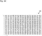
- the weights of the neural network can be processed and/or stored collectively as parameter data.
- An example of such parameter data is in 24 shown.
- AI Artificial intelligence
- This intelligence can be based on programmed processes or generated by machine learning. A distinction is usually made between supervised learning and non-supervised learning.
- supervised learning the algorithm learns a function from given pairs of inputs and outputs.
- a "teacher” provides the correct function value for an input during the learning process.
- the aim of supervised learning is that after several calculations with different inputs and outputs, the neural network is trained to create associations.
- a sub-area of supervised learning is automatic classification.
- the algorithm In the case of unsupervised or unsupervised learning, the algorithm generates a statistical model for a given set of inputs that describes the inputs and contains recognized categories and relationships, thus enabling predictions.
- clustering methods that divide the (raw) data into several categories that differ from one another in characteristic patterns.
- the network thus independently creates classifiers according to which it divides the input pattern.
- An important algorithm in this context is the EM algorithm, which iteratively sets the parameters of a model in such a way that it optimally explains the data seen. He assumes the existence of unobservable categories and alternately estimates the membership of the data in one of the categories and the parameters that make up the categories.
- HMMs Hidden Markov Models
- Other methods of unsupervised learning e.g. B. principal component analysis, dispense with the categorization. They aim to translate the observed data into a simpler representation that reproduces them as accurately as possible despite drastically reduced information.
- Deep learning refers to a method of machine learning that uses artificial neural networks with numerous intermediate layers (English: hidden layers) between the input layer and the output layer and thus an extensive inner structure emerges. It is a special method of information processing known to the person skilled in the art, the understanding of which is a prerequisite for this application.
- Deep learning a special type of machine learning that is commonly understood, uses a series of hierarchical layers, or hierarchy of concepts, to perform the machine learning process.
- the artificial neural networks used here contain so-called neurons, which are connected to one another like a network.
- the first layer of the neural network, the visible input layer processes a raw data input, for example sensor data, such as the individual temperature values from a temperature sensor.
- the Data input contains variables that are accessible to observation, hence this is called the "visible layer”.
- This first layer forwards its outputs to the next layer.
- This second layer processes the information from the previous layer and also passes the result on.
- the next layer receives the information from the second layer and processes it further.
- These layers are called hidden layers.
- the features they contain are becoming increasingly abstract. Their values are not given in the original data. Instead, the model must determine which concepts are useful in explaining the relationships in the observed data. This continues through all layers of the artificial neural network. The result is output in the visible last layer. This breaks the desired complex data processing into a series of nested simple mappings, each described by a different layer of the model.
- neural networks are machine learning models that employ one or more layers of nonlinear units to predict an output for a received input.
- a neural network that has been trained or taught can be used as an AI model (to be trained and trained) for the biomass heating system.
- Some neural networks are deep neural networks that include one or more hidden layers in addition to an output view.
- the output of each hidden layer is used as input to the next layer in the network, i.e. H. the next hidden layer or the output layer.
- Each layer of the network produces an output from a received input in accordance with current values of a corresponding set of parameters.
- the trained neural network is then the core of what is generally referred to as "artificial intelligence".
- TensorFlow TM is a framework for stream-oriented programming. TensorFlow TM is popular in the field of machine learning. The name “TensorFlow” TM comes from arithmetic operations performed by artificial neural networks on multidimensional data fields, so-called tensors. TensorFlow TM was originally developed by the Google Brain team for Google's internal needs and released in 2015 under the Apache 2.0 open source license. With this framework, what is presented later in the exemplary embodiments can be implemented, which means that the person skilled in the art can also derive his understanding of an AI model.
- Machine learning (ML) technology is often understood as a subfield of artificial intelligence.
- the present application also relates to the novel use of artificial intelligence for improved control of a biomass heating system.
- control of valves in recirculation equipment often uses only a primitive step value algorithm based on a single sensed value (usually the boiler temperature), so the air recirculation is subject to regular fluctuations (i.e. the corresponding control loop oscillates). This ultimately makes stationary and optimized control of the boiler output impossible.
- control tasks in conventional biomass heating systems power, lambda, etc.
- Biomass heating systems for pellets or wood chips have the following additional disadvantages and problems.
- biomass heating system should be able to be operated in a fuel-flexible manner with wood chips and pellets, and at the same time have a high level of efficiency.
- the hybrid technology should enable the use of both pellets and wood chips with a water content of between 8 and 35 percent by weight.
- Gaseous emissions that are as low as possible should be achieved.
- Very low dust emissions of less than 15 mg/Nm 3 without and less than 5 mg/Nm 3 with electrostatic precipitator operation are aimed for.
- the task(s) mentioned above or the potential individual problems can also relate to individual partial aspects of the overall system, for example to the regulation and/or control.
- Biomass heating system according to the preceding aspect, wherein the AI model is a neural network with at least 3 layers and at least 200 neurons.
- Biomass heating system according to one of the preceding aspects, wherein the result of the calculation of the trained AI model being used as at least one input variable for a control algorithm, for example a P, PI, PID or PD control.
- a control algorithm for example a P, PI, PID or PD control.
- Method for controlling a biomass heating system for firing solid fuel in the form of pellets and/or wood chips comprising the biomass heating system and the processes according to one of the preceding aspects.
- a computer-readable storage medium containing instructions that, when executed by a computing device, cause the computing device to perform any of the foregoing methods or the operations of any of the foregoing aspects.
- horizontal can denote a level orientation of an axis or a cross section, assuming that the boiler is also set up horizontally, with which, for example, the ground level can be the reference.
- horizontal as used herein means “parallel” to the base plane of the vessel, as commonly defined. Further alternatively, in particular if there is no reference plane, “horizontal” can be understood merely as “parallel” to the combustion plane of the grate.
- an AI model-based control for a biomass heating system independently of the biomass heating system, an AI model-based control for a biomass heating system, the control process of the 18 ff. for a biomass heating system and an optimized self-learning function of the 22 for a biomass heating system and can be claimed independently of this.
- An AI model for a biomass heating system is also disclosed, which can be claimed separately, for example as a control device with an AI model for a biomass heating system.
- the "at least one of the following sensor data" described above for the aspects is an indication of a minimum parameter, with the selection of more than one parameter regularly leading to better behavior of the AI model.
- an expression such as “A or B”, “at least one of “A or/and B” or “one or more of A or/and B” can include any possible combination of features listed together.
- Expressions such as “first “, “secondary”, “primary” or “secondary” used herein represent and do not limit various elements regardless of their order and/or importance.
- an element e.g., a first element
- another element e.g., a second element
- the element may be directly connected to the other element become or are connected to the other element via another element (e.g. a third element).
- a phrase “configured for” (or “configured for”) as used in the present disclosure may be replaced with “suitable for,” “suitable for,” “adapted for,” “made for,” “capable of,” or “designed for.” depending on what is technically possible.
- a phrase “device configured to” or “set up to” may mean that the device can operate in conjunction with another device or component, or perform a corresponding function.
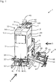
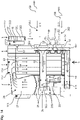
- FIG. 1 shows a three-dimensional overview of the biomass heating system 1 according to an embodiment of the invention.
- the arrow V in the figures indicates the front view of the plant 1
- the arrow S in the figures indicates the side view of the plant 1.
- the biomass heating system 1 has a boiler 11 which is mounted on a base 12 of the boiler.
- the boiler 11 has a boiler housing 13, for example made of sheet steel.
- a combustion device 2 (not shown), which can be reached via a first maintenance opening with a closure 21 .
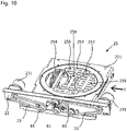
- a rotary mechanism mount 22 for a rotary grate 25 (not shown) supports a rotary mechanism 23 with which drive forces can be transmitted to bearing axles 81 of the rotary grate 25 .
- a heat exchanger 3 (not shown), which can be reached from above via a second maintenance opening with a closure 31 .
- an optional filter assembly 4 (not shown) having an electrode 44 (not shown) suspended by an insulating electrode support 43 and powered by an electrode supply line 42 .
- the exhaust gas of the biomass heating system 1 is discharged via an exhaust gas outlet 41 which is arranged downstream of the filter device 4 (fluidically) in terms of flow.
- a fan can be provided here.
- a recirculation device 5 which a part of the flue or exhaust gas via recirculation channels 51, 53 and 54 and flaps 52 for cooling the combustion process and reuse when Combustion process recirculated.
- This recirculation device 5 will later with reference to Figures 12 to 17 explained in detail.
- the biomass heating system 1 has a fuel supply 6, with which the fuel is conveyed in a controlled manner to the combustion device 2 in the primary combustion zone 26 from the side onto the rotary grate 25.
- the fuel supply 6 has a cell wheel sluice 61 with a fuel supply opening 65, the cell wheel sluice 61 having a drive motor 66 with control electronics.
- An axle 62 driven by the drive motor 66 drives a transmission mechanism 63 which can drive a fuel feed screw 67 (not shown) so that the fuel in a fuel feed channel 64 is fed to the combustion device 2 .
- an ash removal device 7 which has an ash discharge screw 71 in an ash discharge channel which is operated by a motor 72 .
- the biomass heating system 1 also has a control device 100 .
- This control device 100 is provided with a conventional processor, volatile and non-volatile memory (for example (S)RAM, ROM, flash and/or cache memory), and various interfaces. Analogue or digital inputs and outputs can be provided as interfaces. For example, CAN bus interfaces, 0-10V analog inputs or 4-20 mA analog inputs/outputs for sensors and actuators and/or RS-232 interfaces can be provided.
- the control device can preferably (optionally) have at least one interface with an Internet protocol (IP, Ethernet, WLAN) based on the known standards. The control device can thus preferably communicate via the Internet with the data processing devices installed remotely from the biomass heating system 1 .
- IP Internet protocol
- control device 100 can represent part of a distributed system for machine learning, which later in relation to the figures 19 is explained in more detail.
- control device 100 can have a keyboard and/or a display for displaying operating data.
- the display can also have a so-called touch function, with which an operator can make entries on the display.
- a plurality of sensors for detecting physical and/or chemical parameters of the biomass heating system 1 are provided. Examples of such sensors are in relation to the 2 described in more detail.
- One of the sensors that may be communicatively coupled to the controller 100 may be a boiler temperature sensor 115 .
- a combustion chamber 24 or boiler tubes 32 (cf. 2 ) are at least partially covered by a heat exchange medium 38 (cf. 2 ), for example (heating) water.
- the boiler temperature sensor 115 preferably measures or senses the temperature of the heat exchange medium 38 in the boiler 11 at a location representative of an average temperature of the heat exchange medium 38 in the boiler 11 .
- the temperature detected by the boiler temperature sensor 115 is communicated to the control device 100 (preferably as a signal, for example as a voltage signal, as a current signal or as a digital signal), with which the control device 100 can calculate the temperature (which may still have to be calculated from the signal, for example the voltage of 1 volt corresponding to 10 degrees Celsius above zero) is available for further processing.
- the control device 100 preferably as a signal, for example as a voltage signal, as a current signal or as a digital signal
- the control device can store the temperature detected by boiler temperature sensor 115 in a memory (permanent or volatile) and/or use the temperature as training data for machine learning.
- boiler temperature sensor 115 and the detected temperature can also be applied to other sensors and physical or chemical variables, in particular to the sensors which are described later with reference to FIG 2 and 12 to be discribed.
- Sensors can be used, in particular, sensors of the fuel bed height or ember bed height 86, the lambda probe 112, the exhaust gas temperature sensor 111, the vacuum sensor 113, the heating water temperature sensor 114.
- the actuators of the biomass heating system 1 can also be communicatively connected to the control device 100 .
- the air valves 52 of the recirculation device 5, the ignition device 201, the motors 231 and 66, the electrostatic filter 4 or the electrostatic precipitator 4 (e.g. its electrode voltage), the ash removal 7 or its motor 72, the fuel supply 6 with its Cellular wheel sluice 61 or its drive motor 66 or the cleaning device 9 with its drive 91 can be controlled by the control device 100 .
- the control device 100 can thus regulate the biomass heating system 1 .
- At least one detected physical/chemical variable of at least one sensor of the biomass heating system 1 is communicated to the control device 100, the biomass heating system 1 uses this variable(s) to calculate a control response, the control response in turn for setting at least one actuator of the biomass Heating system 1 is used.
- the control response in turn for setting at least one actuator of the biomass Heating system 1 is used. Due to the setting of the at least one actuator, the physical/chemical processes in the biomass heating system 1 (in particular those of combustion) are in turn influenced, which in turn is detected by the at least one sensor. This closes at least one control loop. Due to the large number of possible control tasks of the control device 100, the control device 100 can also control more than one control circuit of the biomass heating system at the same time.
- the regulation of the present biomass heating system 1 is based on artificial intelligence, which in turn was trained with previously recorded sensor data from at least one biomass heating system 1 or can also be optimized “live” during operation.
- the present biomass heating system 1 is thus able to achieve better control results and also to solve control tasks which would otherwise regularly require human intervention during operation or which are error-prone without AI or the use of an AI model 104 . Examples of this are given with reference to the 26 ff. described.
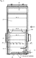
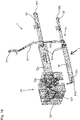
- FIG 2 shows a cross-sectional view through the biomass heating system 1 of FIG 1 , which was taken along a section line SL1 and which is shown viewed from the side S.
- the corresponding 3 which has the same cut as 2 represents, for the sake of clarity, the flows of the flue gas, and fluidic cross-sections are shown schematically. to 3 it should be noted that individual areas compared to the 2 are shown grayed out. This is only for clarity 3 and the visibility of the flow arrows S5, S6 and S7.
- the boiler 11 is mounted on the boiler base 12 and has a multi-walled boiler housing 13 in which water or another fluid heat exchange medium 38 can circulate.
- a water circulation device 14 with a pump, valves, lines, etc. is provided for the supply and removal of the heat exchange medium.
- the combustion device 2 has a combustion chamber 24 in which the combustion process of the fuel takes place in the core.
- the combustion chamber 24 has a multi-part rotary grate 25, which will be explained in more detail later, on which the fuel bed 28 rests.
- the multi-part rotary grate 25 is rotatably mounted by means of a plurality of bearing axles 81 .
- the primary combustion zone 26 of the combustor 24 is encompassed by (a plurality of) combustor brick(s) 29 , whereby the combustor bricks 29 define the geometry of the primary combustion zone 26 .
- the cross-section of the primary combustion zone 26 (for example) along horizontal section line A1 is substantially oval (for example 380mm +/- 60mm x 320mm +/- 60mm; it should be noted that some of the above size combinations may also result in a circular cross-section).
- the arrow S1 schematically reproduces the flow from the secondary air nozzle 291, this flow (this is shown purely schematically) having a swirl induced by the secondary air nozzles 291 in order to improve the mixing of the flue gas.
- the secondary air nozzles 291 are designed in such a way that they introduce the secondary air (preheated by the combustion chamber bricks 29) tangentially into the combustion chamber 24 with its oval cross section there. This creates a flow S1 with vortices or twists, which runs roughly spirally or helically upwards. In other words, a spiral flow running upwards and rotating about a vertical axis is formed.
- the secondary air nozzles 291 are thus aligned in such a way that they introduce the secondary air tangentially into the combustion chamber 24—viewed in the horizontal plane.
- the secondary air nozzles 291 are each provided as an inlet for the secondary air that is not aligned with the center of the combustion chamber.
- such a tangential entry can also be used with a circular combustion chamber geometry.
- All the secondary air nozzles 291 are aligned in such a way that they cause either a right-handed or a left-handed flow.
- each secondary air nozzle 291 can contribute to the formation of the eddy currents, with each secondary air nozzle 291 having a similar orientation.
- individual secondary air nozzles 291 can also be arranged in a neutral (centered) or counter-rotating (opposite orientation) manner, although this may degrade the aerodynamic efficiency of the arrangement.
- the combustion chamber bricks 29 form the inner lining of the primary combustion zone 26, store heat and are directly exposed to the fire.
- the combustion chamber stones 29 thus also protect the other material of the combustion chamber 24 , for example cast iron, from the direct effect of the flames in the combustion chamber 24 .
- the combustion chamber stones 29 are preferably adapted to the shape of the grate 25 .
- the combustion chamber bricks 29 also have secondary air or recirculation nozzles 291, which recirculate the flue gas into the primary combustion zone 26 for renewed participation in the combustion process and in particular for cooling as required.
- the secondary air nozzles 291 are not aligned with the center of the primary combustion zone 26, but are aligned acentrically in order to cause a swirl of the flow in the primary combustion zone 26 (ie a swirling and turbulent flow, which will be explained in more detail later).
- the combustion chamber bricks 29 will be explained in more detail later.
- Insulation 311 is provided at the boiler tube entrance.
- the oval cross-sectional shape of the primary combustion zone 26 (and the nozzle) and the length and position of the secondary air nozzles 291 favor the formation and maintenance of a turbulent flow, preferably up to the ceiling of the combustion chamber 24.
- a secondary combustion zone 27 adjoins the primary combustion zone 26 of the combustion chamber 26, either at the level of the combustion chamber nozzles 291 (from a functional or combustion-related point of view) or at the level of the combustion chamber nozzle 203 (from a purely structural or constructional point of view) and defines the radiant part of the combustion chamber 26.
- the flue gas produced during combustion releases its thermal energy mainly through thermal radiation, in particular to the heat exchange medium, which is located in the two left-hand chambers for the heat exchange medium 38 .
- the corresponding flue gas flows are in 3 indicated purely by way of example by the arrows S2 and S3.
- These turbulent flows may also contain slight backflows or other turbulences, which are not represented by the purely schematic arrows S2 and S3.
- the basic principle of the development of the flow in the combustion chamber 24 is clear and can be calculated by a person skilled in the art based on the arrows S2 and S3.
- oval combustion chamber geometry 24 in particular contributes to the fact that the turbulent flow can develop undisturbed or optimally.
- the nozzle 203 After exiting the nozzle 203, which bundles these turbulent flows again, there are candle-flame-shaped rotary flows S2, which can advantageously reach up to the combustion chamber ceiling 204, so that the available space in the combustion chamber 24 is better utilized.
- the turbulent flows are concentrated in the center of the combustion chamber A2 and make ideal use of the volume of the secondary combustion zone 27 .
- the constriction which represents the combustion chamber nozzle 203 for the turbulent flows, reduces the rotational flows, with which turbulences are generated to improve the mixing of the air/flue gas mixture. Cross-mixing therefore takes place through the constriction or constriction through the combustion chamber nozzle 203 .
- the rotational momentum of the flows is at least partially maintained above the combustion chamber nozzle 203, which maintains the propagation of these flows up to the combustion chamber ceiling 204.
- the secondary air nozzles 291 are integrated into the elliptical or oval cross-section of the combustion chamber 24 in such a way that, due to their length and their orientation, they induce turbulent flows which cause the flue gas/secondary air mixture to rotate and thereby (again in combination with the combustion chamber nozzle 203 positioned above improved) enable complete combustion with minimal excess air and thus maximum efficiency. This is also in the Figures 19 to 21 illustrated.
- the secondary air supply is designed in such a way that it cools the hot combustion chamber bricks 29 by flowing around them and the secondary air itself is preheated in return, whereby the combustion rate of the flue gases is accelerated and the complete combustion even at extreme partial load (e.g. 30% the nominal load) is ensured.
- the first maintenance opening 21 is insulated with an insulating material such as Vermiculite TM .
- the present secondary combustion zone 27 is set up in such a way that burnout of the flue gas is ensured.
- the special geometric design of the secondary combustion zone 27 will be explained in more detail later.
- the flue gas flows into the heat exchange device 3, which has a bundle of boiler tubes 32 provided parallel to one another.
- the flue gas now flows downwards in the boiler tubes 32, as in 3 indicated by the arrows S4.
- This part of the flow can also be referred to as the convection part, since the heat dissipation of the flue gas takes place essentially on the boiler tube walls via forced convection. Due to the temperature gradients in the heat exchanger medium, for example in the water, caused in the boiler 11, natural convection of the water occurs, which promotes thorough mixing of the boiler water.
- the outlet of the boiler tubes 32 opens into the turning chamber 35 via the turning chamber inlet 34.
- the turning chamber 35 is sealed off from the combustion chamber 24 in such a way that no flue gas from the turning chamber 35 can flow directly back into the combustion chamber 24.
- a common (removal) transport path for the combustion residues is provided, which can occur in the entire flow area of the boiler 11. If the filter device 4 is not provided, the flue gas is discharged upwards again in the boiler 11 .
- the other case of the optional filter device 4 is in the 2 and 3 shown. In the process, the flue gas is fed back up into the filter device 4 after the turning chamber 35 (cf. arrows S5), which in the present example is an electrostatic filter device 4. Flow screens can be provided at the inlet 44 of the filter device 4, which even out the inflow of the flue gas into the filter.
- Electrostatic dust filters also known as electrostatic precipitators, are devices for separating particles from gases that are based on the electrostatic principle. These filter devices are used in particular for the electrical cleaning of exhaust gases used.
- electrostatic precipitators dust particles are electrically charged by a corona discharge of a spray electrode and drawn to the oppositely charged electrode (collecting electrode). The corona discharge takes place on a suitable, charged high-voltage electrode (also known as a discharge electrode) inside the electrostatic precipitator.
- the (spray) electrode is preferably designed with protruding tips and possibly sharp edges, because the density of the field lines and thus also the electric field strength is greatest there and the corona discharge is thus favored.
- the opposite electrode usually consists of a grounded section of exhaust pipe that is mounted around the electrode.
- the degree of separation of an electrostatic precipitator depends in particular on the dwell time of the exhaust gases in the filter system and the voltage between the spray and separation electrodes.
- the rectified high voltage required for this is provided by a high-voltage generating device (not shown).
- the high-voltage generation system and the holder for the electrode must be protected from dust and dirt in order to avoid unwanted leakage currents and to extend the service life of system 1.
- a rod-shaped electrode 45 (which is preferably designed like an elongated, plate-shaped steel spring, cf. 15 ) held approximately centrally in an approximately chimney-shaped interior of the filter device 4.
- the electrode 45 consists at least largely of high-quality spring steel or chromium steel and is held by an electrode holder 43 via a high-voltage insulator, ie an electrode insulation 46 .
- the (spray) electrode 45 hangs downwards into the interior of the filter device 4 so that it can vibrate.
- the electrode 45 can, for example, vibrate back and forth transversely to the longitudinal axis of the electrode 45 .
- a cage 48 simultaneously serves as a counter-electrode and as a cleaning mechanism for the filter device 4.
- the cage 48 is connected to ground or earth potential.
- the flue gas or exhaust gas flowing in the filter device 4 is filtered by the prevailing potential difference, cf. the arrows S6, as explained above. in the If the filter device 4 is cleaned, the electrode 45 is de-energized.
- the cage 48 preferably has an octagonal regular cross-sectional profile, as can be seen, for example, in FIG 13 can be taken.
- the cage 48 can preferably be laser cut during manufacture.
- the flue gas flows through the turning chamber 34 into the inlet 44 of the filter device 4.
- the (optional) filter device 4 is optionally provided fully integrated in the boiler 11, so that the wall surface facing the heat exchanger 3 and flushed through by the heat exchange medium is also used for heat exchange from the direction of the filter device 4, with which the efficiency of the system 1 is further improved. In this way, at least part of the wall of the filter device 4 can be flushed with the heat exchange medium, with the result that at least part of this wall is cooled with boiler water.
- the cleaned exhaust gas flows out of the filter device 4 at the filter outlet 47, as indicated by the arrows S7. After leaving the filter, part of the exhaust gas is returned to the primary combustion zone 26 via the recirculation device 5 . This will also be explained in more detail later.
- This waste gas or flue gas intended for recirculation can also be referred to as “Rezi” or “Rezi gas” for short.
- the remaining part of the exhaust gas is conducted out of the boiler 11 via the exhaust gas outlet 41 .
- An ash discharge 7 is arranged in the lower part of the boiler 11.
- sensors are shown which are at least communicatively connected to the control device 100 .
- (Physical and/or chemical) variables of the biomass heating system 1 are recorded with the sensors.
- An exhaust gas temperature sensor 111 is provided downstream of the exit of the heat exchanger 3 . This measures a temperature of the exhaust gas or flue gas after it has flowed through the heat exchanger 3 .
- a conventional temperature sensor or also a PT-100 or PT-1000 sensor can be used as the exhaust gas temperature sensor 111, which is provided in the wall of the exhaust gas duct or protrudes into the exhaust gas duct. With the help of the exhaust gas temperature sensor 111, the temperature of the exhaust gas can be determined in degrees Celsius.
- the exhaust gas temperature sensor 111 can be provided before or after the optional filter device 4, for example. Likewise, for example, the exhaust gas sensor 111 can be provided in front of the exhaust gas outlet 41 . Furthermore, more than one exhaust gas temperature sensor 111 can also be provided in order to increase the accuracy of the measurement or also to provide metrological redundancies. For example, an exhaust gas temperature sensor 111 can be provided directly after the outlet of the heat exchanger 3 and a further exhaust gas temperature sensor 111 can be provided after the filter device 4 .
- At least one lambda probe 112 is also provided. It is intended as a sensor for the lambda control of the biomass heating system 1 . At least one physical/chemical variable that enables the combustion process in the boiler 11 to be regulated is recorded with the lambda probe.
- the lambda probe 112 enables an O2 content measurement or an oxygen content measurement of the exhaust gas or the flue gas after the combustion chamber 24.
- a lambda probe can usually compare the residual oxygen content in the exhaust gas with the oxygen content of a reference, usually the current atmospheric or ambient air. From this, the combustion air ratio ⁇ (ratio of combustion air to fuel) can be determined and set. It can be two Measuring principles are used: Voltage of a solid electrolyte (Nernst probe) and change in resistance of a ceramic (resistance probe).
- the lambda probe 112 can measure the oxygen content of the exhaust gas (e.g. in vol%) and an optimal mixture can thus be controlled on the boiler 11, preferably by means of an AI model, in order to avoid an oversupply of cooling supply air or carbon monoxide (with unused residual calorific value) arising as a result of a lack of oxygen, which would "steal" energy from the heating system.
- the at least one lambda probe 112 are in 2 two possible installation positions are suggested. One is located adjacent to the inlet 33 of the heat exchanger 3 (cf. 2 , above, center) and the other is located in the exhaust gas outlet 41 and thus after the outlet of the heat exchanger 3 (cf. 2 , top right).
- the lambda probe 112 can be provided at any position in the exhaust gas duct of the boiler 11, as long as it can measure the exhaust gas or flue gas.
- An (optional) vacuum sensor 113 or pressure difference sensor 113 is also provided.
- This vacuum sensor 113 measures the (negative) pressure in the combustion chamber 24, for example in the unit [mPas], or the differential pressure of the combustion chamber 24 to the ambient air pressure.
- the primary air (and optionally the secondary air) is sucked into the combustion chamber 24 for combustion via the negative pressure.
- An (optional) return (or flow) temperature sensor 114 or a heating water temperature sensor 114 is also provided. This is provided, for example, in the return or in the flow of a conventional water circulation device 14 and detects the temperature of the heating water in the water circuit in which the boiler 11 is provided.
- the heat exchange medium 38 is preferably the heating water.
- the temperature of the heat exchange medium 38 in or outside the boiler can be detected with the previously explained boiler temperature sensor 115 or with the heating water temperature sensor 114 (preferably a return temperature sensor 114).
- a fuel bed height sensor 116 detects the height of the fuel bed 28 above the grate and thus an amount of the fuel, for example the wood chips, on the grate 25.
- An example of such a sensor is a mechanical version in the EP 3 789 670 B1 in relation to theirs 17 and 18 described, referred to above.
- the fuel bed height sensor 116 can be provided as an ultrasonic sensor, for example.
- a combustion chamber temperature sensor 117 is also provided. This detects a temperature of the combustion chamber 24, for example in degrees Celsius.
- the combustion chamber temperature sensor 117 can be provided at the outlet of the combustion chamber 24 or also in the combustion chamber 24 .
- the locations of the sensors of the 2 and 3 may deviate from the locations shown, as deemed appropriate by those skilled in the art.
- the combustion chamber temperature can also be recorded at a different location.
- the combustor 24 and boiler 11 of this embodiment were calculated using CFD simulations. Furthermore, practical experiments were carried out to confirm the CFD simulations. The starting point for the considerations Calculations for a 100 kW boiler, but considering a power range from 20 to 500 kW.
- the flow processes can be laminar and/or turbulent, accompanied by chemical reactions, or it can be a multi-phase system.
- CFD simulations are therefore well suited as a design and optimization tool.
- CFD simulations were used to optimize the fluidic parameters in such a way that the objects of the invention listed above are achieved.
- the mechanical design and dimensioning of the boiler 11, the combustion chamber 24, the secondary air nozzles 291 and the combustion chamber nozzle 203 were largely defined by the CFD simulation and also by associated practical experiments.
- the simulation results are based on a flow simulation taking heat transfer into account.
- the design of the combustor shape is important in order to be able to meet the task requirements.
- the shape and geometry of the combustion chamber are intended to ensure the best possible turbulent mixing and homogenization of the flow across the cross section of the flue gas duct, minimization of the combustion volume, and a reduction in excess air and the recirculation ratio (efficiency, operating costs), a reduction in CO and CxHx Emissions, NOx emissions, dust emissions, a reduction in local temperature peaks (fouling and slagging) and a reduction in local flue gas velocity peaks (material stress and erosion) can be reached.
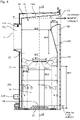
- the 4 showing a partial view of the 2 is, and the figure 5 , which is a sectional view through the boiler 11 along the vertical section line A2, represent a combustion chamber geometry that meets the above-mentioned requirements for biomass heating systems over a wide power range of, for example, 20 to 500 kW.
- the vertical section line A2 can also be understood as the middle or central axis of the oval combustion chamber 24 . In the 4 those sensors are drawn, such as these in relation to the 2 and 3 were explained.
- BK1 172 mm + ⁇ 40 mm , preferably + ⁇ 17 mm
- BK2 300 mm + ⁇ 50 mm , preferably + ⁇ 30 mm
- BK3 430 mm + ⁇ 80 mm , preferably + ⁇ 40 mm
- BK4 538 mm + ⁇ 80 mm , preferably + ⁇ 50 mm
- BK6 307 mm + ⁇ 50 mm , preferably + ⁇ 20 mm ;
- BK7 82 mm + ⁇ 20 mm , preferably + ⁇ 20 mm ;
- BK8 379 mm + ⁇ 40 mm , preferably + ⁇ 20 mm ;
- BK9 470 mm + ⁇ 50 mm , preferably + ⁇ 20 mm ;
- BK10 232 mm + ⁇ 40 mm , preferably + ⁇ 20 mm ;
- BK11 380 mm + ⁇ 60 mm , preferably + ⁇ 30 mm ;
- BK12 460 mm + ⁇ 80 mm , preferably + ⁇ 30 mm .
- the specified size ranges are ranges with which the requirements are (approximately) fulfilled as well as with the specified exact values.
- a chamber geometry of the primary combustion zone 26 and the combustion chamber 24 can preferably be defined using the following basic parameters: A volume with an oval horizontal base measuring 380 mm +- 60 mm (preferably +-30 mm) x 320 mm +- 60 mm (preferably +-30 mm), and a height of 538 mm +- 80 mm ( preferably +- 50 mm).
- the size information given above can also be applied to boilers in other output classes (e.g. 50 kW or 200 kW) scaled in relation to one another.
- the volume defined above can have an upper opening in the form of a combustion chamber nozzle 203, which is provided in the secondary combustion zone 27 of the combustion chamber 24, which has a combustion chamber slope 202 protruding into the secondary combustion zone 27, which preferably contains the heat exchange medium 38.
- Combustion chamber slope 202 reduces the cross section of secondary combustion zone 27.
- Combustion chamber slope 202 is inclined by an angle k of at least 5%, preferably by an angle k of at least 15% and even more preferably by at least an angle k of 19% with respect to an imaginary Horizontal or straight combustion chamber ceiling H (cf. the dashed horizontal line H in 4 ) intended.
- a combustion chamber cover 204 is provided, likewise inclined in the direction of the inlet 33 .
- the combustion chamber 24 in the secondary combustion zone 27 thus has the combustion chamber ceiling 204 which is provided inclined upwards in the direction of the inlet 33 of the heat exchanger 3 .
- This combustion chamber ceiling 204 extends in section 2 at least mostly straight or rectilinear and inclined.
- the angle of inclination of the straight or flat combustion chamber ceiling 204 can preferably be 4 to 15 degrees relative to the (fictitious) horizontal.
- a further (ceiling) slope is provided in the combustion chamber 24 in front of the inlet 33, which forms a funnel together with the combustion chamber slope 202.
- This funnel turns the swirling or eddy flow directed upwards to the side and deflects this flow more or less horizontally. Due to the already turbulent upward flow and the funnel shape in front of the inlet 33, it is ensured that all heat exchanger tubes 32 or boiler tubes 32 are flown evenly, whereby an evenly distributed flow of the flue gas in all boiler tubes 32 is ensured. This optimizes the heat transfer in the heat exchanger 3 considerably.
- the combination of the vertical and horizontal inclines 203, 204 in the secondary combustion zone in combination as the inflow geometry in the convective boiler can achieve a uniform distribution of the flue gas over the convective boiler tubes.
- the combustion chamber slope 202 serves to homogenize the flow S3 in the direction of the heat exchanger 3 and thus the flow through the boiler tubes 32. This causes the flue gas to be distributed as evenly as possible to the individual boiler tubes in order to optimize the heat transfer there.
- the combination of the inclines with the inflow cross section of the boiler rotates the flue gas flow in such a way that the flue gas flow or the flow rate is distributed as evenly as possible over the respective boiler tubes 32 .
- the combustion chamber 24 is provided without dead corners or dead edges.
- the primary combustion zone 26 of the combustion chamber 24 can comprise a volume which preferably has an oval or approximately circular horizontal cross-section on the outer circumference (such a cross-section is shown in 2 marked with A1 as an example).
- This horizontal cross section can also preferably represent the base area of the primary combustion zone 26 of the combustion chamber 24 .
- the combustion chamber 24 can have an approximately constant cross section over the height indicated by the double arrow BK4.
- the primary combustion zone 24 can have an approximately oval-cylindrical volume.
- the side walls and base (grate) of the primary combustion zone 26 may be perpendicular to one another.
- the bevels 203 , 204 described above can be provided as integrated walls of the combustion chamber 24 be, wherein the slopes 203, 204 form a funnel, which opens in the inlet 33 of the heat exchanger 33 and has the smallest cross-section there.
- the horizontal cross section of the combustion chamber 24 and in particular of the primary combustion zone 26 of the combustion chamber 24 can also preferably be regular. Further, the horizontal cross-section of the combustor 24, and particularly the primary combustion zone 26 of the combustor 24, may preferably be a regular (and/or symmetrical) ellipse.
- the horizontal cross section (the outer circumference) of the primary combustion zone 26 can be made constant over a predetermined height (for example, 20 cm).
- An oval-cylindrical primary combustion zone 26 of the combustion chamber 24 is thus provided in the present case, which, according to CFD calculations, enables a significantly more uniform and better air distribution in the combustion chamber 24 than in the case of rectangular combustion chambers of the prior art.
- the lack of dead spaces also avoids zones in the combustion chamber with poor air flow, which increases efficiency and reduces slag formation.
- the nozzle 203 in the combustion chamber 24 is designed as an oval or approximately circular constriction in order to further optimize the flow conditions.
- This optimized nozzle 203 bundles the flue gas-air mixture flowing upwards rotating and ensures better mixing, preservation of the eddy currents in the secondary combustion zone 27 and thus complete combustion. This also minimizes the excess air required. This improves the combustion process and increases efficiency.
- the combination of the secondary air nozzles 291 explained above and the eddy currents induced thereby with the optimized nozzle 203 serves in particular to bundle the flue gas/air mixture rotating upwards. This ensures at least approximately complete combustion in the secondary combustion zone 27.
- a turbulent or swirling flow is bundled through the nozzle 203 and directed upwards, with the result that this flow extends further upwards than is usual in the prior art.
- this is due to the reduction in the distance of the swirling air flow to the rotation or swirl center axis, which is forced by the nozzle 203 (compare analogously to the physics of the pirouette effect).
- the combustion chamber slope 202 of 4 which without a reference number in the 2 and 3 can be seen and where the combustion chamber 25 (or its cross-section) tapers at least approximately linearly from bottom to top, according to CFD calculations ensures that the flue gas flow in the direction of the heat exchange device 4 is made more uniform, which means that its efficiency can be improved.
- the horizontal cross-sectional area of the combustion chamber 25 tapers from the beginning to the end of the combustion chamber slope 202, preferably by at least 5%.
- the combustion chamber slope 202 is on the side of the combustion chamber 25 to the Heat exchange device 4 is provided, and is provided rounded at the point of maximum taper. Parallel or straight combustion chamber walls without a taper (so as not to impede the flue gas flow) are common in the prior art.
- the combustion chamber cover 204 which extends obliquely upwards towards the inlet 33 to the horizontal and diverts the turbulent flows in the secondary combustion zone 27 laterally, thereby equalizing their flow velocity distribution.
- the inflow or deflection of the flue gas flow in front of the tube bundle heat exchanger is designed in such a way that an uneven flow of the tubes is avoided as far as possible, whereby temperature peaks in individual boiler tubes 32 can be kept low and thus the heat transfer in the heat exchanger 4 can be improved (best possible use of the heat exchanger surfaces). . As a result, the efficiency of the heat exchange device 4 is improved.
- the gaseous volume flow of the flue gas is conducted through the inclined combustion chamber wall 203 at a uniform speed (even in the case of different combustion states) to the heat exchanger tubes or the boiler tubes 32.
- This effect is further intensified by the sloping combustion chamber ceiling 204, with a funnel effect being brought about.
- the result is a uniform heat distribution of the heat exchanger surfaces affecting the individual boiler tubes 32 and thus an improved use of the heat exchanger surfaces.
- the exhaust gas temperature is thus reduced and the efficiency increased.
- the flow distribution is particularly at the in the 3 shown indicator line WT1 much more evenly than in the prior art.
- the line WT1 represents an entry surface for the heat exchanger 3.
- the indicator line WT3 indicates an exemplary cross-sectional line through the filter device 4, in which the flow is set up as homogeneously as possible or is approximately evenly distributed over the cross-section of the boiler tubes 32 (due to of flow screens at the entrance of the filter device 4 and due to the geometry of the turning chamber 35).
- a uniform flow through the filter device 3 and the last boiler pass minimizes strand formation and thereby also optimizes the separation efficiency of the filter device 4 and the heat transfer in the biomass heating system 1.
- an ignition device 201 is provided in the lower part of the combustion chamber 25 on the fuel bed 28 . This can cause initial ignition or re-ignition of the fuel.
- the ignition device 201 can be a glow igniter.
- the ignition device is advantageously stationary and offset horizontally to the side relative to the location at which the fuel is introduced.
- the lambda probe 112 can (optionally) be provided after the exit of the flue gas (i.e., after S7) from the filter device.
- a control device 100 can use the lambda probe to identify the respective calorific value.
- the lambda probe 112 can thus enable the ideal mixing ratio between the fuels and the oxygen supply to be regulated. Despite different fuel qualities, the result is high efficiency and higher efficiency.
- a good and flexible control of the (operating) parameters of the combustion and of the biomass heating system 1 serves to maintain or improve the processes in the biomass heating system 1 explained above.
- the adjustment of the actuators based on the sensory feedback by means of AI or trained AI model significantly improves the processes explained above.
- the fuel bed 28 shown shows a rough fuel distribution due to the feeding of the fuel from the right side of the figure 5 .
- This fuel bed 28 is flown from below with a mixture of flue gas and fresh air, which is provided by the recirculation device 5 .
- This flue gas/fresh air mixture is advantageously pre-tempered and has the ideal quantity (mass flow) and the ideal mixing ratio, such as the control device 100 regulates on the basis of various measured values recorded by sensors and associated air valves 52 .
- the burning behavior of the fuel bed can be influenced in particular with the height of the fuel bed, which is detected by the fuel bed height sensor 116 .
- the height of the fuel bed has been shown to be a good indicator that can be used for the AI model, which amount of fuel is available for a burn.
- the height of the fuel bed is also a relevant variable to be controlled for the biomass heating system 1.
- combustion chamber nozzle 203 is shown in which a secondary combustion zone 27 is provided and which accelerates and focuses the flue gas flow. As a result, the flue gas flow is better mixed and can burn more efficiently in the post-combustion zone 27 or secondary combustion zone 27 .
- the area ratio of the combustion chamber nozzle 203 is in a range from 25% to 45%, but is preferably 30% to 40%, and is, for example for a 100 kW biomass heating system 1, ideally 36% +/- 1% (ratio of the measured input area to the measured exit area of the nozzle 203).
- the 6 shows a three-dimensional sectional view (obliquely from above) of the primary combustion zone 26 and the isolated part of the secondary combustion zone 27 of the combustion chamber 24 with the rotary grate 25, and in particular the special design of the combustion chamber bricks 29.
- the 7 shows according to 6 an exploded view of the combustion chamber bricks 29.
- the views of 6 and 7 can preferably with the dimensions listed above 4 and 5 be executed. However, this is not necessarily the case.
- the chamber wall of the primary combustion zone 26 of the combustor 24 is provided with a plurality of combustor bricks 29 in a modular construction which, among other things, facilitates manufacture and maintenance. The maintenance will facilitated in particular by the possibility of removing individual combustion chamber bricks 29.
- Form-fitting grooves 261 and projections 262 are provided in order to create a mechanical and largely airtight connection, in order in turn to prevent the ingress of disturbing external air.
- every two at least largely symmetrical combustion chamber bricks (with the possible exception of the openings for the secondary air or the recirculated flue gas) form a complete ring.
- three rings are preferably stacked on top of one another in order to form the primary combustion zone 26 of the combustion chamber 24 which is oval-cylindrical or alternatively at least approximately circular (the latter is not shown).
- Three further combustion chamber bricks 29 are provided as the upper closure, with the annular nozzle 203 being supported by two retaining bricks 264 which are placed on the upper ring 263 in a form-fitting manner. All bearing surfaces 260 have grooves 261 either for mating projections 262 and/or for the insertion of suitable sealing material.
- the mounting stones 264 which are preferably symmetrical, can preferably have an inwardly inclined bevel 265 in order to make it easier for fly ash to be swept away onto the rotary grate 25.
- the lower ring 263 of the combustion chamber bricks 29 rests on a base plate 251 of the rotary grate 25 . Ash is increasingly deposited on the inner edge between this lower ring 263 of the combustion chamber bricks 29 , which advantageously independently and advantageously seals this transition during operation of the biomass heating system 1 .
- the (optional) openings for the recirculation nozzles 291 or secondary air nozzles 291 are provided in the middle ring of the combustion chamber bricks 29 . There they are Secondary air nozzles 291 are provided at least approximately at the same (horizontal) height of the combustion chamber 24 in the combustion chamber bricks 29 .
- Three rings of combustor bricks 29 are provided here, as this represents the most efficient way of manufacture and also of maintenance. Alternatively, 2, 4 or 5 such rings can also be provided.
- the combustion chamber bricks 29 are preferably made of high-temperature silicon carbide, which makes them very wear-resistant.
- the combustion chamber bricks 29 are provided as shaped bricks.
- the combustion chamber bricks 29 are shaped in such a way that the interior volume of the primary combustion zone 26 of the combustion chamber 24 has an oval horizontal cross section, which means that dead corners or dead spaces, which are usually not optimally flown through by the flue gas/air mixture, are avoided by an ergonomic shape, whereby the fuel present there is not is optimally burned. Due to the present shape of the combustion chamber bricks 29, the flow of primary air through the grate 25, which also suits the distribution of the fuel over the grate 25, and the possibility of unhindered turbulent flows is improved; and consequently the efficiency of combustion is improved.
- the oval horizontal cross section of the primary combustion zone 26 of the combustion chamber 24 is preferably a point-symmetrical and/or regular oval with the smallest inside diameter BK3 and the largest inside diameter BK11.
- FIG 8 shows a plan view of the rotary grate 25 from above seen from the section line A1 of FIG 2 .
- the supervision of 8 can preferably be designed with the dimensions listed above. However, this is not necessarily the case.
- the rotary grate 25 has the base plate 251 as a base element.
- a transition element 255 is provided in a roughly oval-shaped opening in the base plate 251, which bridges a gap between a first rotary grate element 252, a second rotary grate element 253 and a third rotary grate element 254, which are rotatably mounted.
- the rotary grate 25 is provided as a rotary grate with three individual elements, i. i.e. this can also be referred to as a triple rotary grate.
- Air holes are provided in the rotary grate elements 252, 253 and 254 for primary air to flow through.
- the rotary grate elements 252, 253 and 254 are flat and heat-resistant metal plates, for example made of cast metal, which have an at least largely planar configured surface on the upper side and are connected to the bearing axles 81 on the lower side, for example via intermediate mounting elements.
- rotating grate elements 252, 253 and 254 have curved and complementary sides or contours.
- the rotating grate elements 252, 253, 254 can have mutually complementary and curved sides, with the second rotating grate element 253 preferably having concave sides to the adjacent first and third rotating grate elements 252, 254, and preferably the first and third rotating grate elements 252, 254 to the respective second rotary grate element 253 has a convex side. This improves the crushing function of the rotary grate elements, since the length of the fracture is increased and the forces acting to break (similar to scissors) act in a more targeted manner.
- the rotary grate elements 252, 253 and 254 (and their enclosure in the form of the transition element 255) have an approximately oval outer shape when viewed together, which in turn avoids dead corners or dead spaces in which suboptimal combustion could take place or ash could accumulate could accumulate undesirably.
- the optimal dimensions of this outer shape of the rotating grate elements 252, 253 and 254 are in 8 denoted by the double arrows DR1 and DR2.
- the rotary grate 25 has an oval combustion surface, which is more favorable for the fuel distribution, the air flow through the fuel and the combustion of the fuel than a conventional rectangular combustion surface.
- the combustion surface 258 is formed at the core by the surfaces of the rotary grate members 252, 253 and 254 (in the horizontal state). The combustion surface is therefore the upward-pointing surface of the rotary grate elements 252, 253 and 254.
- This oval combustion surface advantageously corresponds to the fuel support surface if this is applied or pushed laterally onto the rotary grate 25 (cf. arrow E of 9 , 10 and 11 ).
- the fuel can be supplied from a direction which is parallel to a longer central axis (main axis) of the oval combustion surface of the rotary grate 25 .
- the first rotary grate element 252 and the third rotary grate element 254 can preferably be configured identically in their combustion surface 258 . Furthermore, the first rotary grate element 252 and the third rotary grate element 254 can be identical or structurally identical to one another. For example, this is in 9 1, with the first rotating grate element 252 and the third rotating grate element 254 having the same shape.
- the second rotary grate element 253 is arranged between the first rotary grate element 252 and the third rotary grate element 254 .
- the rotary grate 25 is preferably provided with an approximately point-symmetrical, oval combustion surface 258 .
- the rotary grate 25 can form an approximately elliptical combustion surface 258, with DR2 being the dimensions of its major axis and DR1 being the dimensions of its minor axis.
- the rotary grate 25 can have an approximately oval combustion surface 258 which is axisymmetric with respect to a central axis of the combustion surface 258 .
- the rotary grate 25 can have an approximately circular combustion surface 258, which entails minor disadvantages in terms of fuel supply and distribution.
- Two motors or drives 231 of the rotary mechanism 23 are also provided, with which the rotary grate elements 252, 253 and 254 can be rotated accordingly. More about the special function and the advantages of the present rotary grate 25 is later with reference to the figures 9 , 10 and 11 described.
- the ash melting range (this extends from the sintering point to the flow point) depends very significantly on the fuel used.
- Spruce wood for example, has a critical temperature of around 1,200 °C.
- the ash melting range of a fuel can also be subject to strong fluctuations. Depending on the quantity and composition of the minerals contained in the wood, the behavior of the ash changes during the combustion process.
- Another factor that can influence slag formation is the transport and storage of the wood pellets or chips. This is because they should reach the combustion chamber 24 as undamaged as possible. If the wood pellets have already crumbled when they enter the combustion process, this increases the density of the ember bed. The result is more slag formation. In particular, the transport from the storage room to the combustion chamber 24 is of importance here. Particularly long distances, as well as curves and angles, lead to damage or abrasion of the wood pellets.
- Another factor relates to the control of the combustion process. So far, efforts have been made to keep the temperatures rather high in order to achieve the best possible burnout and low emissions.
- An optimized combustion chamber geometry and geometry of the combustion zone 258 of the rotary grate 25 makes it possible to keep the combustion temperature at the grate lower and high in the area of the secondary air nozzles 291, and thus to reduce slag formation on the grate.
- the resulting slag (and also the ash) can advantageously be removed due to the special shape and the functionality of the present rotary grate 25 .
- This will now be related to the figures 9 , 10 and 11 explained in more detail.
- the figures 9 , 10 and 11 show a three-dimensional view of the rotary grate 25 with the base plate 251, the first rotary grate element 252, the second rotary grate element 253 and the third rotary grate element 254.
- the views of FIG 9 , 10 and 11 be able preferably correspond to the dimensions listed above. However, this is not necessarily the case.
- This view shows the rotary grate 25 as a free slide-in part with rotary grate mechanism 23 and drive(s) 231.
- the rotary grate 25 is mechanically provided in such a way that it can be individually prefabricated in the manner of the modular system, and as a slide-in part inserted into a provided elongated opening of the boiler 11 and can be installed. This also facilitates the maintenance of this wear-prone part.
- the rotary grate 25 can thus preferably have a modular design, in which case it can be quickly and efficiently removed and reinserted as a complete part with rotary grate mechanism 23 and drive 231 .
- the modularized rotary grate 25 can thus also be assembled and disassembled using quick-release fasteners.
- prior art rotary grates are typically permanently mounted and thus difficult to maintain or assemble.
- the drive 231 can have two separately controllable electric motors. These are preferably provided on the side of the rotating grate mechanism 23 .
- the electric motors can have reduction gears.
- end stop switches can be provided which provide end stops for the end positions of the rotating grate elements 252, 253 and 254 respectively.
- the individual components of the rotary grate mechanism 23 are intended to be exchangeable.
- the gears are provided to be plugged. This facilitates maintenance and also a side change of the mechanics during assembly, if necessary.
- the rotary grate elements 252, 253 and 254 of the rotary grate 25 can each be rotated by at least 90 degrees, preferably at least 120 degrees, even more preferably by 170 degrees, via their respective bearing axles 81, which are driven by the drive 231, in this case the two motors 231, via the rotary mechanism 23 Degrees are rotated about the respective bearing or axis of rotation 81.
- the maximum angle of rotation can be 180 degrees, or a little less than 180 degrees, like the one Allow rust lips 257.
- the rotary mechanism 23 is set up in such a way that the third rotary grate element 254 can be rotated individually and independently of the first rotary grate element 252 and the second rotary grate element 243, and that the first rotary grate element 252 and the second rotary grate element 243 are rotated together and independently of the third rotary grate element 254 be able.
- the rotary mechanism 23 can be provided accordingly, for example by means of running wheels, toothed or drive belts and/or gears.
- the rotary grate elements 252, 253 and 254 can preferably be produced as a cast grate with a laser cut in order to ensure precise shape retention. This in particular in order to define the air flow through the fuel bed 28 as precisely as possible and to avoid disturbing air currents, for example strands of air at the edges of the rotating grate elements 252, 253 and 254.
- the openings 256 in the rotating grate elements 252, 253 and 254 are arranged in such a way that they are small enough for the usual pellet material and/or the usual wood chips not to fall through and large enough for the fuel to flow well with air can be.
- the openings 256 are dimensioned large enough that they can be blocked by ash particles or impurities (e.g. no stones in the fuel).
- ash and/or slag accumulates on the rotary grate 25 and in particular on the rotary grate elements 252, 253 and 254.
- the rotary grate 25 can be cleaned efficiently with the present rotary grate 25 .
- any potential slag formation or slag accumulation on the two outer edges of the third rotary grate element 254 is broken up as it rotates, with the curved outer edges of the third rotary grate element 254 not only shearing off over a greater overall length than with conventional rectangular elements of the stand of the technique, but also with an uneven distribution of movement in relation to the outer edge (there is more movement in the middle than at the bottom and top edges).
- the breaker function of the rotating grate 25 is thus significantly strengthened.
- grate lips 257 (on both sides) of the second rotary grate element 253 can be seen.
- This grate lips 257 are set up such that the first rotary grate element 252 and the third rotary grate element 254 in the closed state of this on the Rest on top of the grate lips 257, and thus the rotary grate elements 252, 253 and 254 are provided to each other without a gap and are thus provided sealing. This avoids strands of air and undesired uneven primary air flows through the bed of embers. This advantageously improves the efficiency of the combustion.
- FIG. 11 shows the rotary grate 25 in the state of universal cleaning, which is preferably carried out during a plant standstill. All three rotary grate elements 252, 253 and 254 are rotated, with the first and second rotary grate elements 252, 253 preferably being rotated in the opposite direction to the third rotary grate element 254. This enables the rotary grate 25 to be completely emptied on the one hand and the ash and slag now broken up on four odd outside edges. In other words, an advantageous 4-fold breaker function is realized.
- the above in relation to 9 What is explained with regard to the geometry of the outer edges also applies with regard to 10 .
- the present rotary grate 25 realizes in addition to normal operation (cf. 9 ) advantageously two different types of cleaning (cf. 10 and 11 ), whereby the partial cleaning allows a cleaning during the operation of the plant 1.
- a 100 kW boiler was simulated in the nominal load operating case with a load range of 20 to 500 kW with different fuels (e.g. wood chips with 30% water content).
- different fuels e.g. wood chips with 30% water content.
- slight soiling or soot was also taken into account for all surfaces in contact with flue gas.
- the emissivity of such a fouling layer was set at 0.6.
- FIG. 12 12 shows an exposed oblique view of the recirculation device 5 with the combustion chamber bricks 29 surrounding the primary combustion zone 26.
- FIG. 13 shows an exposed semi-transparent oblique view of the recirculation device 5 of FIG 12 .
- the 14 shows a side view of the recirculation device 5 of FIG figures 12 and 13 .
- the arrow S of Figures 12 to 14 corresponds to the arrow S of the 1 , which indicates the direction of the side view of the biomass heating system 1.
- the recirculation device 5 is described below with reference to figures 12 , 13 , 14 and 15 described in more detail.
- the recirculation device 5 has a recirculation inlet 53 with a recirculation inlet channel 531 and a recirculation inlet channel divider 532 .
- the recirculation inlet 53 and the recirculation inlet duct 531 are downstream of a fan 15 (cf. 3 ) at the flue gas outlet of the biomass heating system 1 the heat exchanger 3 or after the (optional) filter device 4 is provided.
- the recirculation inlet duct splitter 532 can branch the flue gas to be recirculated or the rezi gas into a primary recirculation duct 56 and an optional secondary recirculation duct 57 . If there is no secondary recirculation, no recirculation inlet channel splitter 532 is required either.
- the primary recirculation duct 56 opens out via an air valve 52, in this case a rotary slide valve 52, for example, in a primary mixing chamber 542.
- a further air valve 52 in this case a rotary slide valve 52, for example, also a primary air duct 58, which in turn has a primary air inlet 581 for space, for example - or fresh air, correspondingly referred to as primary fresh air.
- the primary air duct 58 can have a primary air sensor 582 (for example for detecting the temperature and/or the oxygen content of the primary fresh air and/or the flow rate of the air).
- Unmixed primary air i. H. Fresh air or ambient air
- the primary mixing chamber 542 in which the ambient air is mixed according to the valve position of the air valves 52 with the recirculated flue gas from the primary recirculation channel 56.
- a primary mixing duct 54 is provided downstream of the primary mixing chamber 542, in which the mixture of primary (fresh) air and flue gas is further mixed.
- the primary mixing chamber 542 with its valves 52 and the primary mixing channel 54 together form a primary mixing unit 5a.
- the secondary recirculation channel 57 opens into a secondary mixing chamber 552 via an air valve 52, in this case a rotary slide valve 52, for example.
- a secondary air channel 59 which in turn has a secondary air inlet 591 for secondary fresh air, also opens into the secondary mixing chamber 552 via a further air valve 52, in this case a rotary slide valve 52, for example .
- the secondary air channel 59 can have a secondary air sensor 592 (for example for detecting the temperature and/or the oxygen content of the secondary air and/or the flow rate of the air).
- the fresh secondary air i. H. Ambient air in the secondary mixing chamber 552, in which the ambient air is mixed according to the valve position of the air valves 52 with the recirculated flue gas from the secondary recirculation channel 57.
- a secondary mixing duct 55 is provided downstream of the secondary mixing chamber 552, in which the mixture of secondary fresh air and flue gas is further mixed.
- the secondary mixing chamber 552 with its valves 52 and the secondary mixing channel 55 form the secondary mixing unit 5b.
- valve setting actuator 521 which can be an electric motor, for example.
- the control device 100 can be controlled by the control device 100 to regulate the respective air volume and are communicatively connected to the control device 100 .
- the primary mixing channel 54 has a minimum length L1.
- the minimum length L1 is, for example, at least 700 mm from the beginning of the primary mixing duct 54 at the exit from the primary mixing chamber 542 to the end of the primary mixing duct 54. It has been shown that the length L1 of the primary mixing duct 54 can be longer for good mixing, preferably at least 800 mm mm, ideally 1200 mm. In addition, the length L1 should preferably not exceed 2000 mm, for example, for design and printing reasons.
- the primary mixing duct 54 can have an inlet funnel at its upstream beginning, which tapers towards the end of the primary mixing duct 54 .
- the flow at the upstream beginning of the channel 54 is thus bundled in the middle and mixes even better, since stranding can occur, particularly on the upper side of the channel 54, due to thermal differences. This formation of strands is advantageously counteracted by the narrowing of the primary mixing channel 54 at its beginning.
- the (optional) secondary mixing channel 55 has a minimum length L2.
- the minimum length L2 is, for example, at least 500 mm from the beginning of the secondary mixing duct 55 at the outlet from the secondary mixing chamber 552 to the end of the secondary mixing duct 55. It has been shown that the length L2 of the secondary mixing duct 55 can be longer for good mixing, preferably at least 600 mm mm, ideally 1200 mm. The length L2 should also not exceed 2000 mm, for example, for design and printing reasons.
- the secondary mixing channel 55 can also have an inlet funnel at its upstream start, which tapers in the direction of the downstream end of the secondary mixing channel 55 .
- the primary mixing duct 54 and the (optional) secondary mixing duct 55 can be designed with a rectangular cross section with a respective inner width of 160 mm +- 30 mm (vertical) / 120 mm +- 30 mm (vertical) and an inner thickness (horizontal) of 50 mm +- be executed 15 mm. Due to this design of the primary mixing duct 54 and the secondary mixing duct 55 each as a long, flat duct lying against the heat exchanger 3 and the combustion device, several advantageous effects are achieved. On the one hand, the mixture of flue gas and primary (fresh) air/secondary (fresh) air is advantageously preheated before it is burned.
- a mixture that has a temperature of +25 degrees Celsius downstream of the primary mixing chamber 542 can have a temperature that is 15 degrees Celsius higher at the downstream end of the primary mixing channel 54 in the case of nominal load.
- the cross section and the longitudinal extent are selected to be large enough that the mixing also continues after the mixing chambers 542, 552, which causes an improvement in the homogenization of the flow. In doing so, the flow is provided with sufficient path for a further mixing of the flow, which is already turbulent at the beginning of the path.
- the elongate primary mixing duct 54 provides a path for further mixing after the primary mixing chamber 542, with the primary mixing chamber 542 being purposefully designed to create significant turbulence at the beginning of the path.
- the optional inlet funnel of channels 54, 55 can also contribute to this.
- the two lengths L1 and L2 can preferably match within a certain tolerance (+ ⁇ 10 mm).
- the recirculated flue gas which was previously well mixed with "fresh" primary air, is fed from below to the rotary grate 25 via a primary passage 541 .
- This mixture of recirculated flue gas and fresh primary air i.e., the primary air for the combustor 24
- the primary recirculation for recirculating the mixture of flue gas and primary fresh air is provided in such a way that it enters the primary combustion zone 26 from below.
- the recirculated flue gas which has previously been well mixed with "fresh” secondary air, i.e. secondary fresh air (or if secondary recirculation is omitted, with primary (fresh) air), is directed to the (also optional) recirculation or secondary air nozzles 291 fed.
- the secondary air nozzles 291 are not aligned with the center of the primary combustion zone 26, but rather are aligned off-centre in order to cause a twist in the flow running upwards out of the primary combustion zone 26 into the secondary combustion zone 27 (i.e. an upward Vortex flow with a vertical spin axis).
- the secondary recirculation for recirculating the mixture of flue gas and secondary fresh air can be provided at least partially in the secondary combustion zone 27 .
- the figures 13 and 14 show according to the 12 the course of the flows of the air, the recirculated flue gas and the flue gas-air mixtures in the recirculation device 5 using the (schematic) flow arrows S8 to S16.
- the arrows S1 to S16 indicate the fluidic configuration, ie the course of the flow of the various gases or moving masses in the biomass heating system 1.
- Many of the present components or features are fluidically connected, this being indirectly (ie via other components ) or can be immediate.
- the flue gas which flows out of the heat exchanger 3 and the optional filter device 4 after the heat exchange, enters the recirculation inlet channel 531 of the recirculation device 5 through the recirculation inlet 5 (cf. arrow S8).
- the flue gas from the primary recirculation flows through the primary recirculation duct 56 (see arrow S10), depending on the position of one of the adjustable air valves 52, into the primary mixing chamber 541, in which the flue gas with of the primary fresh air is mixed, which also flows through the primary air duct 58, depending on the position of another of the adjustable air valves 52, into the primary mixing chamber 541 (see arrow S12).
- a mixed flow (cf. arrow S14) of flue gas and fresh primary air is created in the primary mixing duct 54, in which these two components mix advantageously due to the turbulence and the length of the primary mixing duct 54.
- a homogeneous mixture of flue gas and primary fresh air has formed, which flows through the primary passage 541 to the primary combustion zone 26 (cf. arrow S16).
- the flue gas after being divided in the recirculation inlet duct divider 532, flows through the secondary recirculation duct 57 via a further adjustable air valve 52 into the secondary mixing chamber 552 (see arrow S9), in which the flue gas with the over the secondary air duct 59 and a further adjustable valve 52 is also mixed with the secondary fresh air flowing into the secondary mixing chamber 552 (cf. arrow S11).
- This mixing of the flue gas and the secondary fresh air continues in the secondary mixing duct (see arrow S13), which improves the mixing of both components.
- the resulting advantageously homogeneous mixture flows through the secondary passage 551 into the annular channel 50 around the combustion chamber bricks 29 and through the recirculation nozzles 291 into the combustion chamber 24 (cf. arrow S15).
- the physical/chemical parameters of this recirculation can be recorded by the corresponding sensors 582, 592, etc.
- the recirculation (for example the mixing ratio, flow rates, etc.) can be regulated by means of the corresponding actuators 52, 15, etc.
- the schematic block diagram of the 15 shows the above with reference to FIG Figures 12 to 14 Explained flow in the respective individual components of the recirculation device 5, and the biomass heating system 1.
- Both the primary recirculation and the optional secondary recirculation are shown as a complete circuit. Accordingly, the sensors and actuators of the biomass heating system 1 are located, with which the biomass heating system 1 can be controlled.
- the recirculation device 5 can also only have a primary recirculation, cf. 17 .
- the respective valves 52 with the primary mixing chamber 541 and the (preferably approximately horizontally extending) primary mixing channel 54 form the primary mixing unit 5a.
- the respective valves 52 with the secondary mixing chamber 552 and the secondary mixing channel 55 can form the secondary mixing unit 5b.
- Concerning the in 14 hidden parts of the flow guide is on the 3 and the associated explanations.
- the biomass heating system 1 is preferably set up in the present case in such a way that the secondary air entry in the nominal load operating case is reduced to less than 6%, preferably less than 4%, of the air quantity of the mixture of primary fresh air and recirculated flue gas (and if there is secondary recirculation of the air quantity of the mixture of secondary fresh air and recirculated flue gas and the mixture of primary fresh air and recirculated flue gas).
- the in the figures 14 and 15 The sensors 111, 112, 113 and 117 shown, as well as 582 and 592, correspond to those above in relation to FIG Figures 1 to 3 and 12 , as well as in relation to 18 described sensors.
- FIG. 16 shows an exposed semi-transparent oblique view of a recirculation device of a further embodiment.
- Matching reference numbers of 16 reveal essentially the same teaching of 13 , which is why, in order to avoid repetition, only the differences between the two embodiments will be discussed.
- the rotary slide valves of the embodiment of 13 are in the further embodiment 13 been replaced by sliding gate valves.
- the secondary mixing duct 55 was retained as the secondary temperature control duct 55a, fulfilling the function of temperature control of the fresh air.
- the secondary temperature control duct 55a is provided along the wall of the boiler 11, whereby the fresh air, which is supplied from the secondary air duct 59, is preheated by the heat of the boiler 11 before the secondary air is introduced into the combustion chamber 24 (see arrow S13a).
- the secondary temperature control channel 55a is provided with a rectangular cross section, which has a greater (vertical) height than (horizontal) thickness, whereby the secondary temperature control channel 55a "snuggles up" to the boiler wall and the area for heat exchange is kept large. Preheated secondary air increases combustion efficiency.
- the design of the secondary temperature control channel 55a in detail reference is also made to the statements relating to the secondary mixing channel 55 .
- the arrow S15 shows the secondary air flow flowing through the secondary passage 551 into the annular duct 50 around the combustion chamber bricks 29 and through the recirculation nozzles 291 into the combustion chamber 24.
- the arrows S8 and S10 only indicate the flow of the flue gas downstream of the heat exchanger 3 (or the optional filter device 4) to the primary mixing unit 5a, which in this embodiment is constructed more simply and cheaply.
- FIG. 17 shows a schematic block diagram that the flow in the respective individual components of a biomass heating system and the recirculation device 16 disclosed according to the further embodiment.
- the secondary mixing channel 55 can be mechanically identical to the embodiment of FIG 15 be, but is functionally not a duct section for mixing fresh air and Rezi gas, but only serves (this is still the same as the embodiment of the 15 ) the pre-temperature control of the fresh air before it is introduced into the combustion chamber 24.
- the secondary air supply can also be completely dispensed with, in which case the biomass heating system 1 can only be provided with primary recirculation.
- the biomass heating system 1 described above is provided with a control device 100 which has artificial intelligence (AI) or an AI model 104 .
- This AI is prepared by machine learning and allows optimized control of the biomass heating system 1.
- FIG. 18 shows a schematic block diagram with the components of a control of the biomass heating system Figures 1 to 17 .
- the regulation includes the three steps of detecting the relevant physical and/or chemical variables in the biomass heating system 1 by sensors, processing the detected variables in the control device 100, and setting the respective actuators of the biomass heating system 1 as a result of the processing
- the chemical and/or physical variables detected by the sensors can also be referred to as raw data or sensor data from a data technology point of view.
- This sensor data can be analog or digital.
- the first step in detecting the relevant physical/chemical parameters in the biomass heating system 1 can be carried out with the aid of the following sensors, cf figures 1 and 17 and the associated description are carried out: exhaust gas temperature sensor 111, lambda probe 112, vacuum sensor or pressure difference sensor 113, return temperature sensor or heating water temperature sensor 114, boiler temperature sensor 115, fuel bed height sensor 116, 86 and/or combustion chamber temperature sensor 117. At least one primary air sensor 582 and/or a secondary air sensor 592 can also be used. Depending on the application, one or more of these sensors 111-117, 582, 592 can be used. This list is also not necessarily complete, for example external sensors or other sources can provide information about relevant measurement variables or input data for machine learning.
- An air volume sensor (not shown) can also be provided at the exhaust gas outlet 41 or at the outlet or inlet of the blower 15 .
- a flow sensor for measuring, for example, the flow rate of the boiler water or for measuring the flow of the flue gas can also be considered as a sensor.
- Physical quantities are detected by the sensors 111-117 and other sensors, with the result of this detection being transmitted to the control device 100 via a connection 198 .
- Such a transmission can take place, for example, by means of various signals (e.g. digitally via the CAN bus, or analogously via a 4-20 mA signal).
- the sensors are communicatively connected to the control device 100 .
- the control device 100 is provided with sensor data by the sensors 111-117.
- this sensor data can either already be obtained in the sensor (and then, for example, be transmitted as digital values to the control device) and/or also only be obtained in control device 100 from the transmitted signals.
- a so-called smart sensor can be used, for example, which transmits a data via a digital interface transmits a specific temperature value or a pressure value as the sensor data.
- a 0-10V voltage signal from the sensor can be converted into digital values by an A/D converter in control device 100, and the digital values can then be converted (for example using a conversion formula) into the sensor data which, for example, indicates a temperature or a represent pressure.
- the control device 100 has at least one input interface, at least one output interface, a memory and a processing unit for processing the recorded data in the second step.
- a machine learning unit 101 is also provided, which can be provided, for example, as a software module or a separate hardware module in order to carry out machine learning. The function of the machine learning unit 101 will be discussed later in relation to the 22 explained in more detail.
- the machine learning unit 101 can be provided in the control device 100, as in FIG 18 shown, or also separately from the control device 100, for example in a central processing unit 190 (cf. Figures 19a until c) or as a separate module of control device 100.
- a number of recorded physical quantities which are stored in the form of sensor data, are selected and then used to train a corresponding model, which in turn is then iteratively evaluated and optimized until the model's prediction accuracy is considered to be sufficient.
- a sufficiently optimized model is then used as an AI model for the ongoing operation of the biomass heating system.
- the control device 100 can also have an optional user interface 102 or a user interface 102 (e.g. a display, a touchscreen, a keyboard, a network device such as a tablet PC or a cell phone, etc.), which is particularly suitable for training with the machine learning unit 101 can be used can.
- a user interface 102 e.g. a display, a touchscreen, a keyboard, a network device such as a tablet PC or a cell phone, etc.
- the model can be optimized and evaluated with or without user support.
- the control device 100 can include a memory for storing the detected physical and/or chemical quantities and/or the result of the machine learning.
- the actuators are adjusted in a third step in order to optimize the regulation of the biomass heating system.
- the result of the machine learning is used to influence or directly control the control behavior of the biomass heating system 1 .
- the actuators include, for example and not exclusively, the valves 52, 52s (or the air flaps), the rotary valve 61, the ignition device 201, the motors of the rotary grate 231, the fuel supply or the drive motor 66, the ash discharge 71, 72, the cleaning drive 91, the filter device 4, the water circulation device 14 and the blower 15. Other actuators not mentioned here can also be controlled. These actuators can be communicatively connected to the control device 100 via a connection 198, for example analog or digital.
- the first, second and third step can preferably be carried out iteratively in the sense of a control loop.
- connection 198 is unidirectional, it can of course also be bidirectional, for example by means of a bus system.
- control device 100 which contains the machine learning unit 101, communicates with various sensors and actuators of the biomass heating system 1.
- the control device can first carry out machine learning at the processor in order to set an AI.
- the AI can then enable optimized control of the biomass heating system 1 .
- the step of processing the detected variables includes in control mode, ie during normal operation of the biomass heating system 1, using an AI model (104) with which the setting of various actuators using selected sensor data or at least one filtered variable is calculated. More information can be found in the Figures 20 to 22 .
- the AI model is parameterized using machine learning.
- the AI model is thus trained in a learning mode in which stored quantities or sensor data are used.
- the machine learning has the function of extracting, e.g., a useful rule, a knowledge representation, and/or a determination criterion based on an analysis of a data set input to the device, outputting the determination results, and learning the knowledge (machine learning).
- a variety of learning techniques are available, which are roughly classified into, for example, “supervised learning”, “unsupervised learning” and “reinforcement learning” as discussed above.
- To implement these techniques another technique called “deep learning” is available, which involves self-learning to extract feature magnitudes.
- GPGPU General-Purpose Computing on Graphics Processing Units
- computers with high computing power allows for higher processing speed.
- a (preferably large) number of data sets of specific inputs and results (labels) are introduced into or supplied to the control device 100, which learns the relationships or features contained in these data sets and inductively creates a model for predicting or estimating the Result learned from the input, ie their relationship.
- Supervised learning is applicable to this embodiment, for example, for use in classifying the fuel used (e.g., wood chips or pellets).
- Supervised learning can be realized by using an algorithm such as a neural network (explained in detail later).
- the categories of data into which the data sets of the sensor data are to be classified are referred to as “labels”.
- labels are the output or the result on which the model is trained.
- a classification model returns a label as a result.
- a label is the basis for optimizing the model to a "statement”.
- labels are predefined for a specific application.
- unsupervised learning only input data in a large amount is introduced into a learning unit of the controller 100, which learns a distribution or characteristic of the input data and in turn carries out learning with a device that compresses, classifies, and the introduced data, for example forms without corresponding interactions with a user being required for learning. This makes it possible, for example, to combine features or characteristics seen in these data sets into similar features or characteristics.
- the result obtained can be used to define certain criteria and to allocate outputs in an optimized way according to the criteria and thus to predict an output. It should be noted that unsupervised learning does not require this additional information, since the associated algorithms operate purely on the data content. Unsupervised machine learning works on data similarities, but not on previously defined categories.
- a solution to the problem lying between unsupervised learning and supervised learning, which is referred to as semi-supervised learning, is also applicable to the present biomass heating system 1 . This is true when, for example, only some data serve as records of inputs and outputs and the rest of the data consist of only inputs. In this aspect, learning can be effectively performed by applying data (e.g., image data or simulation data) even without actual combustion in the biomass heating system 1 .
- data e.g., image data or simulation data
- FIG. 1 shows a device and a method for local learning (ie on-site learning in, on or near the biomass heating system 1). Consequently, all the components are present on or in the biomass heating system 1 so that the machine learning can be carried out.
- Supervised learning can be carried out, for example, with the help of a user who accompanies a machine learning learning process on a touch screen.
- the biomass heating system 1 can iteratively run through a number of "learning cycles", with the system 1 being in operation and the sensors detecting the required variables and transmitting them to the control device 100 . These captured Variables are stored in the control device 100 and then enable the machine learning described above by means of the learning unit 101. Depending on the type of machine learning, this can be done by means of a user interface 102, for example a display on the biomass heating system 1 or a mobile phone or a tablet PC, which are connected to the control device 100 via a network, also take place with the involvement of the user or not.
- a user interface 102 for example a display on the biomass heating system 1 or a mobile phone or a tablet PC, which are connected to the control device 100 via a network, also take place with the involvement of the user or not.
- FIGS 19a, 19b and 19c show schematic block diagrams of devices and methods with exemplary components of the biomass heating system of FIG Figures 1 to 17 , this being in contrast to 18 based on a core machine learning approach.
- a plurality of biomass heating systems 1 can be connected to a central computing device 190, for example a server 190, via a network connection 199, for example the Internet.
- the sensors and the actuators correspond to those of the Figures 1 to 17 and the 18 .
- the aim of this central configuration is to collect data or variables from a plurality of biomass heating systems 1 and then make them available for learning so that the resulting AI models are based on a broader or better database.
- FIGS. 19a and 19b show for reasons of clarity only a single biomass heating system 1 and a single control device 100. As in synopsis with Figure 19c can be seen, however, a plurality of biomass heating systems 1 and a plurality of control devices 100 is provided in the central approach, which correspondingly in the Figures 19a and 19b need to be supplemented mentally.
- the biomass heating system 1 with its sensors and actuators (left block) is connected to the control device 100 (middle block) via a connection 198 .
- the control device 100 is in turn connected to a central computing device 190 or a server 190 (right block) via a network connection 199 (for example an Internet Protocol (IP) connection via the Internet).
- IP Internet Protocol
- Corresponding interfaces are, as in 18 , present.
- the left block of each Figure 19a and the Figure 19b (the biomass heating system 1) roughly corresponds to the left and right blocks of the 18 .
- the individual details of the left and right blocks 1, 1 der 18 not stated repeatedly.
- the left block 1 of Figure 19a and the Figure 19b thus includes the regarding 18 sensors and actuators mentioned as examples.
- at least one connection 198 to the control unit 100 (middle block 100 of the Figure 19a ) provided, with which signals from the sensors / actuators of the biomass heating system 1 can be transmitted to the control unit 100 and back.
- the controller 100 of the biomass heating system (s) 1 of Figures 19a and 19b has an AI model 104 which is used to control the biomass heating system 1 . Furthermore, in the control device 100, sensor data or detected chemical and/or physical parameters of the biomass heating system 1 are buffered in a memory 105a. These collected chemical and/or physical variables are then transmitted to the central computing device 190 or the server 190, which consequently collects physical/chemical variables from a plurality of control devices 100 and stores them in a memory 105b.
- Figures 19a,b and c Sensor data or chemical and / or physical parameters of a plurality of biomass heating systems 1 aggregated.
- a learning unit 101 of the server 190 can thus carry out machine learning based on aggregated chemical and/or physical quantities of a plurality of biomass heating systems.
- the central processing unit 190 can, for example, query the sensor data or stored variable(s) from the control device 100 at regular intervals, or the control device 1 of the biomass heating system can independently request the variables or sensor data at regular intervals or when other triggering conditions occur transmitted to the central processing unit 190.
- the transmission can take place using standard network protocols and technologies.
- the principle applies that the larger the amount of training data, the greater the prediction accuracy of the model.
- 20 shows a schematic diagram representing a (example) model for a neuron, which is a possible basis of machine learning.
- 21 shows a schematic diagram representing a three-layer neural network obtained by summarizing in 21 neurons shown is formed.
- Neural networks are preferred as learning models for supervised learning and unsupervised learning (or as approximation algorithms for value functions in reinforcement learning).
- the neural network is realized by, for example, an arithmetic unit, an arithmetic device, and a memory, which are a basic concept of a neuron such as in FIG 20 shown, reproduce mathematically.
- the neurons serve to provide an output (result) y for multiple inputs x ( 20 represents the three inputs x1 to x3 as a possible example).
- Each input x(x1,x2,x3) is multiplied by a weight w(w1,w2,w3) equal to input x.
- An exemplary three-layer neural network constructed by computationally meshing in 20 shown neurons is formed below with reference 21 described.
- the inputs x1, x2 and x3 are multiplied by a weight corresponding to each of three neurons N11 to N13, and these are then input to the neurons.
- the weights used to multiply these inputs are collectively referred to herein as W1.
- 21 z11 to z13 are collectively referred to as feature vectors Z1 and can be regarded as vectors obtained by extracting the feature amounts from input vectors.
- the feature vectors Z1 are defined between the weights W1 and W2.
- Z11 to Z13 are multiplied by a weight corresponding to each of the two neurons N21 and N22 and then input to the neurons.
- the weights used to multiply these feature vectors are collectively referred to herein as W2.
- Neurons N21 and N22 output z21 and z22, respectively.
- z21 and z22 are collectively referred to as feature vectors z2.
- the feature vectors Z2 are defined between the weights W2 and W3.
- z21 and z22 are multiplied by a weight corresponding to each of three neutrons N31 to N33 and input. The to multiply these feature vectors
- the weights used are collectively referred to herein as W3.
- a neural network processes a plurality of input data and outputs a calculated plurality of output data.
- a neural network provides an adaptive calculation function for processing input data.
- this calculation function is an AI model which processes input data from sensors in the biomass heating system 1 and outputs corresponding output data for controlling the actuators in the biomass heating system 1 .
- the weight W is learned (or adapted) using a learning data set in the learning mode, and an output or control variable is determined as an output in the prediction mode or control mode using the weight W.
- Variables or sensor data that are called up while the biomass heating system 1 is being operated with its control device 100 in the control mode can also be learned at the same time and directly, and can thus be reflected in the subsequent action (this is also referred to as "online Learning”, whereby learning mode and control mode coincide in this variant).
- a set of pre-collected data can be used to perform "collective learning” and subsequently run the control mode using these quantities (this is referred to as collective or batch learning and referred to herein with reference to 22 discussed in more detail).
- the learning mode can be interposed each time a certain amount of data has been accumulated.
- the weights W1 to W3 can be learned by the error feedback method.
- Information from errors enters on the right and flows to the left.
- the error feedback method is used to adjust (learn) each weight to reduce the difference between the true output y (teacher) and the output y when input x is input. This can also be referred to as training or parameterizing the model.
- Such a neural network can also have more than three layers (this is called deep learning).
- the number of neurons can be predefined in an application-specific manner.
- the type of networking of the neurons can deviate from the example above.
- control device 100 with the machine learning unit 101 for machine learning can have a neural network that is used as a value function or AI model.
- the neural network described above can thus form a basis for machine learning, which is described below in the context of the biomass heating system 1 explained herein.
- 22 10 shows a block diagram representing a basic concept of a data flow or a process of machine learning of a biomass heating system (ie the learning mode of the AI model 104) and the associated execution of the learned model (ie the control mode of the AI model 104).
- This basic concept can be applied to the regulation of the biomass heating system 1, with the following figures 26 ff. Examples of such applications. the figures 23 and 24 show additions too 22 .
- parameters of an AI model 104 are changed or optimized by an iterative learning process in the learning mode. For example, weights of a neural network are changed.
- parameters relating to the basic setting of the AI model can also be changed in learning mode, for example; for example, the number of neurons in a neural network could be changed.
- a trained AI model with its learned (fixed) parameters is used in the control mode in order to calculate specific output values from input values.
- step S20 sensor data or the variables detected by the sensors # are made available. This can be done using currently recorded data (with online learning) or stored sensor data can be used as a starting point (e.g. with batch learning).
- the sensor data are preferably stored in a memory 105, 105a of the control device 100 or central computing device 190. In this case, this sensor data can be recorded, for example, as respective data sets for a physical and/or chemical variable over a predetermined period of time and stored in memory 105, 105a.
- this data can also be prepared for training as the first part of the training data.
- this can be done automatically, for example, reference data can be stored automatically with the sensor data, or these training data can be prepared manually from the sensor data by combining them with a so-called “learning input”.
- the sensor data can be provided by a user, for example, with the desired results or the target specifications as learning input (this addition is optional).
- a user can supplement sensor data for training with his knowledge of the origin of the data.
- An example of this is the detection or classification of fuel.
- the recorded sensor data e.g. temperature, lambda values, etc.
- from various combustion processes can be supplemented by the user by specifying the label of the fuel.
- a number of sensor data can be supplemented with the label “pellets”, and a further number of sensor data can be supplemented manually with the label “wood chips”. This can also further optimize the learning process of the AI model 104 .
- data sets with sensor data relating to the use of fuel identification can be provided by a user with supplementary data relating to the fuel identification.
- a user can thus provide the sensor data with result data (for example, it is specified for a set of sensor data that these measurements were made with pellets as fuel), which are then made available together as the first part of the training data for the next step S21.
- step S21 data filtering takes place.
- the data filtering is used for the targeted selection and preparation of sensor data and/or the first part of the training data for learning/training (step S23) the model.
- This data filtering can also be referred to as feature extraction.
- filter techniques can preferably be used which reduce the amount of data for learning/training.
- filter techniques can also be used, which remove incorrectly recorded data or data that is not well suited for learning/training.
- the selection using a selection filter is probably the most important point of the data filtering of step S21.
- the sensor data that is to be used for machine learning is always selected first. For example, it specifies that sensor data is only used by certain sensors. Consequently, the AI model with predefined sensor data work. In addition, the exact time period of the data can also be specified during the selection.
- step S21 data can be filtered by selecting sensor data, which can be selected according to the type of sensor data and/or the time period of the sensor data.
- each label is the name of a particular concept, category, or class of data that the model is learning to recognize.
- a label can be the type of fuel, for example, or the “combustion chamber temperature” label, whereby all sensor data recorded by combustion chamber temperature sensor 117 are referred to as sensor data with the “combustion chamber temperature” label.
- step S22 these labels are combined with the filtered sensor data or the first part of the training data, with a corresponding data matrix of labels and filtered and prepared sensor data being created.
- the labels provided the second part of the training data.
- This data matrix thus contains the complete training data for the AI model 104.
- Step S23 relates to the actual learning/training of the model.
- a predefined/preconfigured neural network is trained, which is thus in the learning mode.
- the number of neurons (which are also referred to as “nodes” in programming) and the number of layers in the neural network are usually predetermined or can be adapted to the application, depending on the application of the model. For example, 600 neurons can be used in 3 layers. However, if, for example, the complexity of the application is greater and the prediction accuracy of the AI model 104 is not satisfactory, the number of neurons can be increased. In essence, the AI model learns from its input how "good" the previous calculation was and changes its parameterization accordingly to optimize its prediction accuracy.
- the prediction accuracy of the AI model 104 has usually improved significantly, whereby the parameterization of the AI model 104 has been optimized.
- This parameterization for example the weights of the neural network, can be processed and stored as parameter data 106 (cf. 24 as an example).
- the result of the learning process is therefore largely contained in the parameter data 106 .
- step S23 the training of the model, a parameterized model is created, which is stored as such in step S24.
- This model is preferably a parameterized neural network with its weights.
- the basic parameters of the neural network are basically predefined, but the weightings or weightings of the neural network change in step S23.
- the weightings of the neural network are thus variable parameters of the model, which are changed application-specifically with learning.
- parameter data that reflect the weights of a parameterized neural network.
- a number stands for a weight of the neural network.
- the position of the number in the data also indicates the position of the weight in the neural network. It is therefore sufficient to store the parameter data, for example as an array or as a string in the manner shown, in order to adequately define the variable parameters of the neural network. Otherwise, parameter data can also contain other parameters, for example the number of layers required.
- step S25 of 22 an evaluation of the model is carried out. This can either be done automatically (for example, a desired level of accuracy is not achieved) or a manual evaluation is carried out by a user.
- Steps S23, S24, S25 and optionally S21 are carried out iteratively (in at least two runs, more likely in dozens or even hundreds of runs or so-called epochs), with the learning/training of the model being repeated in order to improve the accuracy/prediction quality of the to improve the model.
- this iteration usually leads back to retraining step S23.
- the evaluation of the model can also show that, for example, sensor data from another sensor is required or that filter parameters have to be adjusted. In this respect, the iteration can also lead back to step S21 in exceptional cases.
- Figures 23a and 23b Examples of learning curves as a result of the iterative learning/training of the model, which were obtained during training of the model for fuel identification of the biomass heating system with data sets from this system.
- the "epoch” horizontal axis refers to the number of iterations, with one (1) “epoch” denoting one (1) pass in training the model.
- the vertical axis "cross entropy" generally explains the accuracy of the model; the smaller the value on this axis, the better or more accurate it is.
- the cross entropy is a measure of the quality of a model for a probability distribution. Minimizing the cross-entropy with respect to the model parameters is equivalent to maximizing the log-likelyhood function.
- the solid line shows the cross entropy of training and the dashed line the cross entropy of validation.
- the model's prediction accuracy increases with the number of training runs. It should be noted that the larger the number of available training data for each iteration (for each epoch), the more effective the training.
- the trained parameters, ie parameter data 106, or the entire AI model 104 is/are then transferred to the control device 100 of the biomass heating system 1. This can then carry out an optimized regulation of the biomass heating system 1 .
- sensor data is provided. These can either be provided directly by sensors during operation by detecting at least one physical and/or chemical parameter, or detected sensor data can be retrieved from memory 105, 105a of control device 100 (in which these are temporarily stored).
- step S31 The sensor data provided are again subjected to data filtering in the following step S31.
- This step S31 usually corresponds to step S21, to which reference is made.
- This creates a data vector or feature vector with the filtered data for the AI model 104.
- This data vector is supplied to the AI model 104 in the control mode.
- the weights of the model usually remain unchanged.
- a model result, which is used in the following step S40, is calculated with the aid of the AI model.
- step S40 the model result is converted into concrete instructions for controlling at least one actuator of the biomass heating system 1. If the model result indicates, for example, that a certain type of fuel has been recognized, corresponding presettings (for example a position of a valve 52 of the recirculation device 5) are retrieved.
- At least one actuator of the biomass heating system 1 is then set/controlled in step S41.
- the temperature in the combustion chamber 24 can change due to the change in a position of a valve 52 of the recirculation device 5 .
- sensor data relating to the combustion chamber temperature will in turn change.
- a control circuit is thus present, with which the biomass heating system 1 can be controlled by means of the AI model.
- the combustion process can first be prepared in the optional step S50.
- the biomass heating system can be mechanically and electronically initialized.
- the operating system of the control device 100 starts up, a self-test of the electronics is carried out and/or the rotary grate elements 252, 253, 254 are rotated (opened) by a predetermined angle in order to remove any deposits on the grate and the mechanics forward to test a combustion process.
- the rotary (transmitter) sensors can be used to check whether activation of the motors 231 of the rotary mechanism leads to the desired result, or whether something is blocked.
- the mechanical boiler cleaning via tubulators), the ash removal and the optional electrostatic precipitator cleaning for a predefined Time (e.g. 30 seconds) are operated.
- the airways of the boiler 11 can also be flushed. To do this, the biomass heating system is flushed with air by opening the primary air and secondary air valves. Then the air slides are closed and the flue gas recirculation line is purged.
- the combustion chamber 24 is filled with fuel.
- the fuel is conveyed to the rotary grate 25 via the fuel supply 6 until a predetermined height of the fuel bed is reached.
- the fuel bed height is measured with the fuel bed height sensor 116 .
- the fuel bed level sensor 116 is, for example, a mechanical level flap 86 with a rotation angle sensor.
- step S52 the fuel is ignited in step S52.
- This can also be referred to as the ignition phase.
- Energy is supplied to the fuel via the ignition device 201 until it burns.
- the valves or valve positions can be set in such a way that they promote the ignition of the fuel.
- the blower 15 is also activated in order to generate a corresponding negative pressure in the combustion chamber 24 .
- the primary air and secondary valves can be set to predefined values (e.g.: 60% and 15%) and a predefined negative pressure in the combustion chamber (e.g. 75 Pa) is regulated.
- step S53 the stabilization of the combustion.
- This step also referred to as the stabilization phase, further promotes ignition of the fuel bed.
- the positions of the air valves 52, the function of the blower 15 and also the fuel supply are adjusted accordingly.
- the boiler 11 and also the combustion chamber 24 should continue to heat up.
- the combustion process should gradually transition to a stationary state in which there is an equilibrium from a thermodynamic point of view. If the combustion temperature increases up to a predetermined value, for example 400°C, step S53 is completed.
- step S54 the stabilized combustion and the actual heating operation.
- the power output or the combustion intensity is controlled by means of the fuel supply 6, the blower 15, the position of the valves 52, and other actuators based on the sensor data from sensors of the biomass heating system 1, for example based on the combustion chamber temperature, the Lambda value and/or the boiler (water or medium) temperature.
- combustion air ratio supplied air quantity divided by the minimum air quantity required for combustion of the fuel under stoichiometric conditions
- a fuel-flexible output control is used in the present biomass heating system 1 .
- the fuel insert is adjusted depending on the fuel, taking into account the fuel quality and the power requirement.
- the clocking of the fuel feeder can be changed in such a way that the fuel bed height measured by the fuel bed sensor remains in a predetermined height range (separately for each type of fuel).
- the adaptation of the fuel injection cycle takes place step by step in defined time intervals (e.g.: 120 seconds).
- the settings of the actuators for the minimum and maximum power for different fuel qualities have to be specified manually by the user (by manually selecting a fuel). If this were not done, then it could be the case, for example, that the combustion of a fuel with a low water content is controlled with the settings that apply to a fuel with a high water content. In this case, a higher fuel conversion and thus an excessively high output would be achieved. This results in excessive thermal combustion chamber loads, which reduce the service life of the system (increase material loads) and can cause increased emissions.
- the specification for the position of the primary air valve and the combustion chamber vacuum at maximum output can be made for a wood chip fuel of the usual quality (design fuel), i.e. with a water content in the upper third of the permitted fuel spectrum.
- design fuel i.e. with a water content in the upper third of the permitted fuel spectrum.
- a corresponding fuel detection is using the 26 explained in more detail.
- Step S54 is ended when, for example, sufficient heat output has been made available.
- step S55 the combustion chamber 24 and in particular the rotary grate 25 are burned out.
- the fuel supply is stopped and the combustion chamber temperature drops. It burns the remains of the fuel on the rotary grate 25.
- the positions of the valves 52, the fan 15 can be adjusted accordingly.
- the rotary grate 25 is cleaned by turning or opening the rotary grate elements accordingly.
- step S55 the method can be deactivated (END), or after some time the method can go back to step S50, with which a new heating cycle begins.
- FIG. 26 shows a schematic diagram of an exemplary application of machine learning to identify or classify the fuel of the biomass heating system 1.
- the Figures 27a , 27b and 27c show corresponding sensor data from sensors used for this application (for training and for prediction).
- the abbreviation "HK” (for wood chips) designates sensor data from the detection of wood chips
- the abbreviation "PL” (for pellets) designates sensor data from the detection of pellets.
- These variables can preferably be detected in a period of time that is defined from the ignition (i.e. from the activation of the ignition device 201) until a threshold value of preferably 16% O2 is reached. Alternatively, a longer period can be used.
- the Figure 27a purely by way of example, the course of a temperature of the exhaust gas after the ignition of wood chips (HK) and, in comparison, of pellets (PL) (cf. horizontal axis, ignition takes place at time 0) in a cut-out period.
- the exhaust gas temperatures were recorded with the exhaust gas temperature sensor 111 in each case. Both temperature diagrams of wood chips and pellets show the same period after ignition (the extension of the horizontal axis was omitted in the temperature diagram for pellets for the sake of clarity)
- Figure 27b shows purely as an example for the same period as Figure 27a comparing the corresponding oxygen content curves, which were determined with the lambda probe 112, for pellets and wood chips. It can be seen here that the corresponding temperature curves are quite similar.
- the Figure 27c again shows purely by way of example for the same period as Figure 27a comparing the corresponding combustion chamber temperature curves, which were determined with the combustion chamber temperature probe 117, for pellets and wood chips. Despite the similar course of the curve, clear differences in temperature can be seen here. For example, the temperature curve for the wood chips (HK) ends at around 900°C, while the temperature curve for the pellets (PL) ends at around 1150°C
- sensor data it is illustrated again what can be understood by sensor data.
- it is sensor data that is recorded over a period of time and reflects a physical or chemical variable.
- the sensor data of the exhaust gas temperature sensor 111 includes the temperature of the exhaust gas over time.
- the time period of the sensor data can advantageously be limited to a time period that is particularly characteristic of the application. It has been shown, for example, that the type of fuel, especially after it has been ignited, leads to sensor data that is characteristic and thus easily distinguishable for an AI.
- This sensor data selected according to time and source can be used to train the AI model 104 and to execute the AI model 104 during operation of the boiler 11 in order to classify the fuel.
- this classification can not only relate to the general type of fuel, but also roughly divide the fuel into its quality (especially its water content).
- a classification model is assigned the 26 sensor data shown (or the oxygen content of the exhaust gas of the biomass heating system and at least one of the two in 26 other sizes shown) and also the associated labels. These labels are in 26 not shown separately for the sake of clarity, since these are of course already included in the context of the respective recorded variable.
- a classification model Given enough training data (often hundreds or thousands of sensor data or even datasets per label), a classification model can learn to predict whether new data belongs to one of the classes it was trained on. This prediction process is called inference.
- Each row of this example corresponds to a label of the training data (ie the second part of the training data).
- the classification with the highest probability can be determined accordingly by means of this output of the probabilities.
- the label 1 would be classified or recognized.
- label 1 could be pellets, label 2 for wood chips and label 3 for elephant grass, with which pellets would be recognized as fuel in the present example.
- the prediction result of the AI model 104 which is to be statistically classified regularly, is evaluated by the control device in such a way that the result with the greatest prediction probability is used as the final result of the model 104.
- Labels called “fuel quality 1 . . . 10” could now be used as further labels relating to the quality of the fuel, which is an indicator of the quality of the fuel on a scale of 1 to 10 (from poor to very good), for example.
- the AI model 104 could be provided with further labels in the second part of the training data in order to classify the fuel even more precisely.
- the numerical values output by the AI model which are also sorted by label (e.g. oxygen content 16.1% (vol%), oxygen content 16.2%, oxygen content 16.3"...) with their probabilities be issued.
- One of the properties of the present biomass heating system 1 that is to be emphasized is that it should be able to be fired in a hybrid manner.
- a wide variety of carbon-based solid fuels can be used, such as wood chips or pellets, but also reed grass (miscanthus or elephant grass) or olive shells.
- the aforementioned fuels usually have very different burning behavior. Due to their natural origin, such biogenic fuels do not usually burn in the same way, although there are now a number of standards relating to fuels, such as pellets. So (even with standardized fuels) the length, the dust content, the type of wood, etc. of the fuel vary. In addition, the consistency or the water content of the fuel can vary greatly. This can also be caused, for example, by improper storage or non-quality-assured production of the fuel.
- the type of fuel determines the control parameters of the biomass heating system 1 significantly, which in turn strongly influences the combustion process.
- the detection of the fuel influences or determines the operation of the actuators of the boiler 11, for example the control parameters of the air valves, the material supply quantity of the fuel or the cleaning process of the boiler 11 (e.g. cleaning intervals and intensity).
- incorrect identification of the fuel usually leads to a reduction in the efficiency of the biomass heating system 1 to the point of malfunctions in the biomass heating system 1 during operation, for example due to increased slagging.
- Incorrect material detection can also lead to a delay in the start-up of the boiler 11 or to a long start-up time, a rapid drop in performance and a loss of performance.
- conventional biomass boilers 1 have a major problem in correctly classifying the type (and quality) of the fuel, since they usually rely purely on spot measurements from the lambda sensor.
- the type of fuel in conventional biomass heating systems 1 is regularly determined only by means of the oxygen content of the exhaust gas/flue gas and associated threshold values in steady-state operation, for example after 30 minutes or more. Experiments have shown that this rudimentary implementation of fuel identification has a comparatively high error probability and, moreover, can fail completely with more than two fuels for classification due to the lack of ability to allocate the oxygen measurement to a specific fuel.
- the fuel is determined with a delay, which means that the boiler 11 is already started up with permanently set parameters, and the control of the boiler 11 is thus adapted to the type of the fuel can only take place at a late point in time in the combustion process.
- the detection accuracy or classification accuracy of the fuel can be significantly improved.
- the type of fuel can be determined on the one hand, and optionally also the quality of the fuel.
- This determines various basic settings of the biomass heating system 1 .
- the various basic settings for example basic valve positions of the valves 52, fan working ranges of the fan 15, etc.
- these basic settings are retrieved and applied.
- the lambda of the exhaust gas, the combustion chamber temperature, the flue gas temperature and, in addition to increasing the accuracy of the model, the time from ignition to reaching a predefined combustion chamber temperature and the time from ignition to reaching a predetermined fuel bed height can be recorded.
- 29 shows a method for fuel bed height control of the biomass heating system 1 of FIG Figures 1 to 24 with an AI model 104.
- An AI model 104 for fuel bed height control is provided with a preset target fuel level and sensor data of at least one of the following variables: Lambda or O2, combustion chamber temperature, flue gas temperature, ignition time (i.e. the time from initiation of ignition to to reach a predetermined temperature in the combustor) and fill time (i.e. the time from the start of fuel injection into an empty combustor until a predetermined fuel bed height is reached).
- phase of (regulated) combustion has proven to be particularly advantageous as a time period for the sensor data, in which the height of the fuel bed should ideally be kept quite constant at an "ideal value" in order to keep the amount of fuel available and thus the fuel energy constant to keep.
- the result of the execution of the AI model 104 in training or "learning" (ie in the training mode, which is referred to as learning mode here) and in ongoing operation (ie in the control mode) can preferably be supplied as a control parameter to a control algorithm 107, which Motor 66 drives the fuel supply 66 and is informed by the height sensor 116 of the height of the fuel bed.
- a control algorithm 107 can be a conventional P, PI, PID, PD algorithm in which, however (in contrast to the prior art) one of the control parameters is at least influenced by the (further) control parameter of the AI model 104 .
- the result of the AI model 104 may be the P, I, or D term of the control algorithm, or at least a portion thereof (e.g., a P term of the AI model in a predefined range of values may be added to a predefined offset).
- the P component or the I component of a PID algorithm can come from the AI model 104 .
- all control parameters of the control algorithm 107 can also come from the AI model 104 .
- control algorithm 107 can also be used for all other controls explained here (cf. Figures 18 to 34 ).
- the result of the calculation of the AI model 104 can be used directly to control an actuator etc. (e.g. the boiler 11 can be switched on or off) or the result of the calculation of the AI model 104 can be used as an input variable for a control algorithm 107 serve, which performs control calculations.
- the result of the calculation of the AI model 104 can also be used to set basic settings (for example control ranges of the air valves 52, cleaning intervals, etc.) of the biomass heating system 1. An example of this would be the result of the classification of the fuel. If a specific fuel is detected, a cleaning interval corresponding to the fuel is set.
- the biomass heating system 1 can "learn" to better regulate the height of the fuel bed, taking into account the specifics of the system (i.e., taking into account the type of fuel and the specifics of the biomass heating system 1 itself).
- the AI can be used to determine what level is required to achieve the desired energy class of the boiler 11 using the parameters from now and from previous data.
- FIG. 30 shows a method for lambda control or for oxygen content control of the exhaust gas of the biomass heating system Figures 1 to 24 with an AI model.
- the aim of the method is an optimized lambda control of the biomass heating system 1.
- the lambda value or oxygen (residual) content of the exhaust gas is, as already explained, a decisive factor that influences the quality and efficiency of the combustion process.
- the AI model 104 the Combustion process in the biomass heating system 1 optimized.
- Sensor data of at least one of the following variables is made available to an AI model 104 for lambda control: detected lambda or O2, combustion chamber temperature, exhaust gas temperature, negative pressure in the combustion chamber, position or degree of opening of the at least one primary valve 52, position or degree of opening of the at least one secondary valve 52, and fuel bed height.
- the desired power output of the boiler 11 is also made available to the AI model 104 as a default.
- phase of (regulated) combustion (step S54) has proven to be particularly advantageous as a time period for the sensor data for the application for lambda control, since lambda control to an optimum lambda value has the greatest effect in this time period in terms of efficiency and cleanliness of the combustion process.
- the biomass heating system thus calculates which lambda level is optimal to work with the parameters and how the behavior was in the past with these settings, especially with secondary air and with outlet air.
- FIG. 31 shows a method for on/off control of the biomass heating system Figures 1 to 24 with an AI model 104.
- One of the basic rule decisions when heating a house or similar is the decision to activate or not activate the biomass heating system at the right time.
- an occurring heat wave can make the use of the biomass heating system 1 superfluous.
- An AI model 104 for lambda control is provided with sensor data from the following variables: a predetermined energy class of the biomass heating system 1 (e.g. 50 or 120 kW, i.e. the capacity of the biomass heating system 1), the current temperature of a heating water buffer ( or to put it more generally: a currently available amount of heat for heating), optionally a specified time to react to a change in the weather, and data on the development of the weather.
- a predetermined energy class of the biomass heating system 1 e.g. 50 or 120 kW, i.e. the capacity of the biomass heating system 1
- the current temperature of a heating water buffer or to put it more generally: a currently available amount of heat for heating
- optionally a specified time to react to a change in the weather e.g. 50 or 120 kW, i.e. the capacity of the biomass heating system 1
- a predetermined energy class of the biomass heating system 1 e.g. 50 or 120 kW, i.e. the capacity of the biomass heating system 1
- the data on the development of the future weather preferably includes the (outside) temperatures over a period of one (1) day or up to three days.
- data can be used that contain, for example, the temperatures predicted by the weather service at the location where the biomass heating system 1 is set up every hour.
- the future weather data may include data about future snowfall and/or future rainfall. Indicators about the future power requirement for heating with the biomass heating system 1 can be derived from this weather data.
- future weather data is the data retrieved from a weather service as a forecast can be and which allow a prediction of an expected power requirement of the biomass heating system 1.
- a suitably trained AI model can make an optimized forecast of the time at which the ( Combustion in the) biomass heating system 1 is activated or deactivated.
- FIG. 32 shows a method for weather-dependent power control of the biomass heating system Figures 1 to 24 with an AI model.
- a conventional power output regulation of a heating system is usually carried out using thermostats on the radiators and an outside temperature sensor, with which the general power requirement of the system is estimated.
- many other weather factors can at least influence the general power requirement of the heating system, for example rain, snow, solar radiation and standstill, wind, etc.
- a power output from a heating system is usually only determined with the current temperature, a forward-looking control of the power output based on a weather forecast not usual.
- an AI model for weather-dependent power control is used here, which on the one hand can work with foresight and on the other hand can also avoid excessive power fluctuations.
- AI model 104 receives at least one of the following variables as sensor data: detected lambda or O2, combustion chamber temperature, exhaust gas temperature, negative pressure in the combustion chamber, position or degree of opening of the at least one primary valve 52, position or degree of opening of the at least one secondary valve 52, fuel bed height , as well as water flow into or out of the boiler, a boiler temperature (or, in relation to the two above variables, formulated more generally: a heat quantity sensor relating to the heat quantity given off by the boiler, for example a flow quantity sensor with a temperature sensor and associated calculation of the heat quantity).
- phase of (regulated) combustion (step S54) has proven to be particularly advantageous as a time period for the sensor data for use in power control.
- the AI model 104 continues to receive the boiler target output as a default.
- the AI model 104 also receives at least current weather data, for example the current outside temperature at the location of the biomass heating system 1, and preferably additional weather data, such as the position of the sun.
- the AI model 104 may receive weather forecast data over a predefined future time period, such as in relation to the 31 already explained.
- the result of the AI model 104 can be fed to a control algorithm 107, as described above in relation to FIG 29 already explained what is referred to.
- control algorithm 107 will adjust the output power of the boiler, which in turn is recorded by means of suitable sensors as the actual boiler output.
- the actual boiler output is in turn fed to the control algorithm 107 as a control input variable.
- Figure 33 shows a method for (now weather-independent) output control or temperature control of the biomass heating system Figures 1 to 24 with an AI model 104.
- the AI model 104 uses at least two of the following variables or the resulting sensor data: Combustion chamber temperature, boiler temperature, amount of heat given off (determined, for example, by means of a heat amount sensor, which determines the flow rate and the temperature of the water flowing through and uses this to determine the amount of heat) , fuel bed height.
- phase of (regulated) combustion (step S54) has proven to be particularly advantageous as a time period for the sensor data for use in power control.
- the result of the AI model 104 is in turn fed to a control algorithm 197 .
- This controls towards a boiler temperature, which in turn is detected by the boiler temperature sensor 115, from which in turn a deviation T2-T1 (setpoint temperature T2 minus detected boiler temperature T1) is determined, which in turn is fed to the control algorithm 107.
- FIG. 34 shows a method for primary air control of the biomass heating system Figures 1 to 24 with an AI model.
- the position or the degree of opening of the at least one primary valve 52 and also of the secondary valve 52 have significant influences on the optimization of the combustion process in the boiler 11 .
- a regulation can also be used here contribute significantly to optimization using an AI model.
- the AI model 104 uses at least two of the following variables or the resulting sensor data: Combustion chamber temperature, boiler temperature, amount of heat given off (determined, for example, by means of a heat amount sensor, which determines the flow rate and the temperature of the water flowing through and uses this to determine the amount of heat) , fuel bed height.
- phase of (regulated) combustion (step S54) has proven to be particularly advantageous as a time period for the sensor data for use in power control.
- the position of the at least one secondary valve can be derived directly from the result of the AI model 104 and the position of the at least one primary valve 52.
- the actual output of the boiler 11 is recorded and included in a differential control of the position of the at least one primary valve 52 depending on the actual output of the boiler 11 and the position of the primary valve 52 .
- the primary air is also reduced if the secondary air is above a specified target value.
- the target value of the primary air for a specific output can be maintained and with the help of the learning process of the KI model 104 from "old data", small adjustments to the system can be optimized from the secondary air by means of the position of the secondary air flap Calculate and adjust the setting parameters of the valves 52 accordingly. In this way, fluctuations in the boiler airflow system can be significantly reduced
- the recirculation device 5 is described here with a primary recirculation and a secondary recirculation. However, in its basic configuration, the recirculation device 5 can also only have a primary recirculation and no secondary recirculation. With this basic configuration of the recirculation device, the components required for the secondary recirculation can be omitted completely, for example the recirculation inlet channel divider 532, the secondary recirculation channel 57 and an associated secondary mixing unit 5b, which will be explained later, and the recirculation nozzles 291 can be omitted.
- only one primary recirculation can be provided in such a way that the secondary mixing unit 5b and the associated channels are omitted, and the mixture of the primary recirculation is not only fed under the rotary grate 25, but also (e.g. via another channel) to the is supplied to the recirculation nozzles 291 provided in this variant.
- This variant is mechanically simpler and therefore less expensive, but still has the recirculation nozzles 291 for creating a swirl in the flow in the combustion chamber 24 .
- rotary grate elements 252, 253 and 254 instead of only three rotary grate elements 252, 253 and 254, two, four or more rotary grate elements can also be provided.
- five rotary grate elements could be arranged with the same symmetry and functionality as with the three rotary grate elements presented.
- the rotary grate elements can also be shaped or designed differently from one another. More rotary grate elements have the advantage that the crushing function is increased.
- convex sides of the rotary grate elements 252 and 254 concave sides of these can also be provided, in which case the sides of the rotary grate element 253 can be shaped in a complementary convex manner. This is functionally almost equivalent.
- Fuels other than wood chips or pellets can also be used as fuels in the biomass heating system.
- olive skins, elephant grass and biogenic waste can be used as additional fuels.
- the biomass heating system disclosed here can also be fired exclusively with one type of fuel, for example only with pellets.
- the fuel identification can also be used in such a way that the quality (eg the water content) of only one fuel is identified.
- the combustion chamber blocks 29 can also be provided without the recirculation nozzles 291 . This can apply in particular to the case in which no secondary recirculation is provided.
- the rotational flow or turbulent flow in the combustion chamber 24 can be clockwise or counterclockwise.
- the combustion chamber cover 204 can also be provided with an incline in sections, for example in a stepped manner.
- the secondary (re)circulation can also only be flown with secondary air or fresh air, and in this respect not recirculate the flue gas, but only supply fresh air.
- the secondary air nozzles 291 are not limited to purely cylindrical bores in the combustion chamber bricks 291 . These can also be designed as frustoconical openings or tapered openings.
- the recirculation device 5 in the embodiment of 12 with a primary recirculation and a secondary recirculation.
- the recirculation device 5 can also only have a primary recirculation and no secondary recirculation.
- the components required for the secondary recirculation can be omitted completely, for example the recirculation inlet channel divider 532, the secondary recirculation channel 57 and an associated secondary mixing unit 5b, which will be explained, and the recirculation nozzles 291 can be omitted.
- only one primary recirculation can be provided in such a way that the secondary mixing unit 5b and the associated channels are omitted, and the mixture of the primary recirculation is not only fed under the rotary grate 25, but also (e.g. via another channel) to the is supplied to the recirculation nozzles 291 provided in this variant.
- This variant is mechanically simpler and therefore less expensive, and nevertheless has the recirculation nozzles 291 for creating an eddy current or twist in the flow in the combustion chamber 24 .
- An air quantity sensor, a vacuum unit, a temperature sensor, an exhaust gas sensor and/or a lambda sensor can also be provided or only at the inlet of the flue gas recirculation device 5 .
- the sensors 111 to 117 can be provided in any suitable location for measuring the respective quantities, and as such the locations for these sensors not limited to the locations shown in the figures.
- the position of the sensors 111, 112, 113, 114, 116 and 117 etc. is only shown as an example in the figures and can vary as long as the respective intended operating variable can be detected directly or indirectly (e.g. by corrective calculation).
- sensors or actuators than indicated in the figures can also be provided.
- 26 ff Only certain sensors are required, with only a part of the 26 ff. specified sensors may be sufficient.
- the described principle applies that the respective AI models can provide better predictions the more input data is used for training and execution. In this respect, the AI models described here are all the more accurate the more sensors with corresponding sensor data are used.
- part of the training data can be obtained on site and the model can be trained with it, and this can then be further trained centrally with training data from other biomass heating systems.
- Actuators which are not explicitly mentioned here also come into consideration as actuators which are regulated by the biomass heating system 1 .
- the term "actor” includes any actor, regardless of whether it directly or indirectly influences the combustion processes in the biomass heating system or not. For example, an indication on a display showing the result of the identification of the fuel (the classification of the fuel) can be understood as an "actor” within the meaning of this application. According to a special understanding, however, the term “actor” of this disclosure can also be understood as just an actor which can influence the combustion processes in the biomass heating system 1 (for example an (air or water) valve, a fan, a heating water pump, a rotary grate servomotor, a motor for cleaning the biomass heating system 1.
- an (air or water) valve for example an (air or water) valve, a fan, a heating water pump, a rotary grate servomotor, a motor for cleaning the biomass heating system 1.
- weather forecast data Any data that provides information about the future development of the weather (e.g. temperature developments, probability of rain, etc.) can be understood as weather forecast data.
- data is usually provided online by so-called weather services in a predetermined data format, with which it can be processed by the AI model 104 after pre-filtering. Protocols for retrieving the weather forecast data are known to the person skilled in the art and are required for this application in terms of content.
- a computer program which may also be referred to or described as a program, software, software application, application, module, software module, script, or code, may be written in any form of programming language, including compiled or interpreted languages, or declarative or procedural Languages; and may be employed in any form, including as a specific program, or as a module, component, subprogram, or other suitable entity for use in a computing environment.
- a program can, but does not have to, use one match file in a file system.
- a program may be stored in a portion of a file that holds other programs or data, e.g. one or more scripts stored in a tracking language document, in a single file dedicated to the program in question, or in multiple coordinated files, e.g. B. Files that store on one or more modules, subprograms, or sections of code.
- a computer program may be employed to run on one computer or on multiple computers located at one location or distributed across multiple locations and linked by a data communications network.
- the methods and logic flows described in this specification may be performed by one or more programmable computers executing one or more computer programs to perform functions by operating on input data and generating an output.
- the methods and logic flows can also be implemented by special purpose logic circuitry, e.g. FPGA or ASIC, or by a combination of special purpose logic circuitry and one or more programmed computers.
- Suitable computers for executing a computer program may be based on general purpose or special purpose microprocessors or both, or on any other type of central processing unit.
- a central processing unit receives instructions and data from read-only memory or random access memory, or both.
- the essential elements of a computer are a central processing unit for executing instructions and one or more memory devices for storing instructions and data.
- the central processing unit and the memory can be supplemented by or integrated into special purpose logic circuitry.
- a computer also includes one or more mass storage devices for storing data or is operatively connected to one or more mass storage devices for receiving data therefrom or transferring data thereto, e.g. B. magnetic, magneto-optical or optical disks.
- a computer need not have such devices.
- a computer in another device be embedded, e.g. a cellular phone, a personal digital assistant (PDA), a mobile audio or video player, a games console, a global positioning system (GPS) receiver, or a portable storage device, e.g. B. a universal serial bus (USB) stick, just to name a few.
- PDA personal digital assistant
- GPS global positioning system
- USB universal serial bus
- Suitable computer-readable media for storing computer program instructions and data include all forms of non-transitory memory, media and storage devices, including, by way of example, semiconductor memory devices, e.g. B. EPROM, EEPROM and flash memory devices; magnetic discs, e.g. B. internal hard drives or removable drives; magneto-optical discs; and CD-ROM and DVD-ROM discs.
- semiconductor memory devices e.g. B. EPROM, EEPROM and flash memory devices
- magnetic discs e.g. B. internal hard drives or removable drives
- magneto-optical discs e.g. B. CD-ROM and DVD-ROM discs.
- embodiments of the content described in this specification may be run on a computer having a display device, e.g. a CRT (cathode ray tube) or LCD (liquid crystal display) monitor, for displaying information to the user, and a keyboard and pointing device, e.g. a mouse or trackball, through which the user can provide input to the computer.
- a display device e.g. a CRT (cathode ray tube) or LCD (liquid crystal display) monitor
- keyboard and pointing device e.g. a mouse or trackball
- Other types of devices can also be used to provide interaction with a user; e.g. B.
- Feedback provided to the user can be any form of sensory feedback, e.g. B. visual feedback, audible feedback or tactile feedback; and input from the user can be received in any form, including auditory, verbal, or tactile input.
- a computer may interact with a user by sending documents and receiving documents from a device used by the user; e.g. B. by sending web pages to a web browser on a user's device in response to requests received from the web browser.
- a computer can communicate with a user by sending text messages or other forms of messages to a personal device, e.g. a smartphone running a messaging application and receiving replying messages from the user.
- Data processing devices such as controller 100, for implementing machine learning models may also include, for example, special purpose hardware accelerators for processing common and computationally intensive parts of machine learning training or production, i. H. interference, loads, include.
- Machine learning models can be executed and applied using a machine learning framework, e.g., a TensorFlow framework, a Microsoft Cognitive Toolkit framework, an Apache Singa framework, or an Apache MXNet framework.
- a machine learning framework e.g. For example, a TensorFlow framework, a Microsoft Cognitive Toolkit framework, an Apache Singa framework, or an Apache MXNet framework.
- Embodiments of the content described in this specification may be executed on a computer system that includes a back-end component, e.g. as a data server, or comprising a middleware component, e.g. an application server, or that includes a front-end component, e.g. B. a client computer with a graphical user interface, web browser or application through which a user can interact with an execution of the content described in this description, or any combination of one or more such back-end, middleware or Front End Components.
- the components of the system may be connected by any form or medium of digital data communication, e.g. B. a communication network. Examples of communication networks include a local area network (LAN) and a wide area network (WAN), e.g. B. the Internet.
- LAN local area network
- WAN wide area network
- the computer system can include clients (the biomass heating system 1 ) and at least one server 190 .
- clients the biomass heating system 1
- server 190 At least one server 190 .
- a client and server are generally remote from each other and typically interact through a communications network.
- the client and server relationship is created by computer programs running on the respective computers having a client-server relationship with each other.
- the biomass heating system disclosed herein serves to burn biogenic solid fuel.
- the basic principles of the teaching explained herein can also be applied to gaseous fuel.
- the present AI model (or the teaching of claim 1) can also be applied to a heating system that burns product gas (e.g. from a biomass gasifier).
- product gas e.g. from a biomass gasifier.
- the methods disclosed herein and also the basic principles of learning the AI model 104 and the execution of the control can also be used.
Landscapes
- Engineering & Computer Science (AREA)
- Mechanical Engineering (AREA)
- General Engineering & Computer Science (AREA)
- Chemical & Material Sciences (AREA)
- Combustion & Propulsion (AREA)
- Life Sciences & Earth Sciences (AREA)
- Environmental & Geological Engineering (AREA)
- Wood Science & Technology (AREA)
- Sustainable Development (AREA)
- Sustainable Energy (AREA)
- Solid-Fuel Combustion (AREA)
- Regulation And Control Of Combustion (AREA)
Abstract
Biomasse-Heizanlage (1) zur Verfeuerung von biogenem Brennstoff, aufweisend: einen Kessel (11) mit einer Brenneinrichtung (2) und mit einem Wärmetau-scher (3); eine Steuereinrichtung (100) mit einem Speicher (105, 105a); zumindest einen Sensor (86, 111-117, 582, 592) zur Bereitstellung von Sensor-daten, welcher zumindest eine chemische und/oder physikalische Größe der Bio-masse-Heizanlage (1) erfassen kann und welcher mit der Steuereinrichtung (100) kommunikativ verbunden ist; zumindest einen Aktor (4, 5, 52, 6, 61, 66, 7, 72, 91, 201, 231) der Biomasse-Heizanlage (1), welcher mit der Steuereinrichtung (100) kommunikativ verbunden ist und von dieser angesteuert werden kann; wobei die Steuereinrichtung (100) zumindest ein KI-Modell (104) zur Regelung der Biomasse-Heizanlage (1) basierend auf den bereitgestellten Sensordaten beinhaltet, wobei das KI-Modell (104) mittels maschinellem Lernen parametriert wird.Biomass heating system (1) for burning biogenic fuel, comprising: a boiler (11) with a combustion device (2) and with a heat exchanger (3); a controller (100) having a memory (105, 105a); at least one sensor (86, 111-117, 582, 592) for providing sensor data, which can detect at least one chemical and/or physical variable of the biomass heating system (1) and which communicates with the control device (100). connected is; at least one actuator (4, 5, 52, 6, 61, 66, 7, 72, 91, 201, 231) of the biomass heating system (1), which is communicatively connected to the control device (100) and can be controlled by it ; wherein the control device (100) contains at least one AI model (104) for controlling the biomass heating system (1) based on the sensor data provided, the AI model (104) being parameterized using machine learning.
Description
Die Erfindung betrifft eine Biomasse-Heizanlage mit einer mittels maschinellem Lernen optimierten Steuereinrichtung und ein entsprechendes Verfahren.The invention relates to a biomass heating system with a control device optimized by means of machine learning and a corresponding method.
Insbesondere betrifft die Erfindung eine Biomasse-Heizanlage mit einer optimierten Regelung durch eine Steuereinrichtung, welche ein durch maschinelles Lernen optimiertes Regelverhalten aufweist.In particular, the invention relates to a biomass heating system with optimized regulation by a control device, which has a control behavior optimized by machine learning.
Biomasse-Heizanlagen, insbesondere Biomasse-Kessel, in einem Leistungsbereich von 20 bis 500 kW sind bekannt. Biomasse kann als ein günstiger, heimischer, krisensicherer und umweltfreundlicher Brennstoff angesehen werden. Als verfeuerbare Biomasse beziehungsweise als biogene Festbrennstoffe gibt es beispielsweise Hackgut oder Pellets.Biomass heating systems, in particular biomass boilers, in a power range from 20 to 500 kW are known. Biomass can be considered a cheap, domestic, crisis-proof and environmentally friendly fuel. There are, for example, wood chips or pellets as combustible biomass or biogenic solid fuels.
Die Pellets bestehen meistens aus Holzspänen, Sägespänen, Biomasse oder anderen Materialien, die in kleine Scheiben oder Zylinder mit einem Durchmesser von ca. 3 bis 15 mm und einer Länge von 5 bis 30 mm verdichtet worden sind. Hackgut (auch als Holzschnitzel, Holzhackschnitzel oder Hackschnitzel bezeichnet) ist mit schneidenden Werkzeugen zerkleinertes Holz.The pellets usually consist of wood shavings, sawdust, biomass or other material that has been compacted into small discs or cylinders approximately 3 to 15 mm in diameter and 5 to 30 mm long. Wood chips (also known as wood chips, woodchips or woodchips) are wood that has been crushed with cutting tools.
Biomasse-Heizanlagen für Brennstoffe in Form von Pellets und Hackgut weisen im Wesentlichen einen Kessel mit einer Brennkammer (der Verbrennungsraum) und mit einer daran anschließenden Wärmetauschvorrichtung auf. Aufgrund der in vielen Ländern verschärfter gesetzlicher Vorschriften weisen einige Biomasse-Heizanlagen auch einen Feinstaubfilter auf. Regelmäßig ist weiteres verschiedenes Zubehör vorhanden, wie beispielsweise Brennstoff-Fördereinrichtungen, Regelungseinrichtungen, Sonden, Sicherheitsthermostate, Druckschalter, eine Rauchgas- bzw. Abgasrückführung, eine Kesselabreinigung und ein separater Brennstoffbehälter.Biomass heating systems for fuels in the form of pellets and wood chips essentially have a boiler with a combustion chamber (the combustion chamber) and a heat exchange device connected to it. Due to the stricter legal regulations in many countries, some biomass heating systems also have a fine dust filter. Other various accessories are regularly available, such as fuel delivery devices, control devices, probes, safety thermostats, pressure switches, flue gas or exhaust gas recirculation, boiler cleaning and a separate fuel tank.
Bei der Brennkammer sind regelmäßig eine Einrichtung zur Zuführung von Brennstoff, eine Einrichtung für die Zufuhr der Luft und eine Zündvorrichtung für den Brennstoff vorgesehen. Die Einrichtung zur Zufuhr der Luft weist wiederum normalerweise ein Gebläse mit niedrigem Druck auf, um die thermodynamischen Faktoren bei der Verbrennung in der Brennkammer vorteilhaft zu beeinflussen. Eine Einrichtung zur Zuführung von Brennstoff kann beispielsweise mit einem seitlichen Einschub vorgesehen sein (sog. Quereinschubfeuerung). Dabei wird der Brennstoff von der Seite über eine Schnecke oder einen Kolben in die Brennkammer eingeschoben.A device for supplying fuel, a device for supplying air and an ignition device for the fuel are regularly provided in the combustion chamber. In turn, the means for supplying the air normally comprises a low-pressure fan in order to favorably influence the thermodynamic factors of combustion in the combustion chamber. A device for supplying fuel can be provided, for example, with a lateral insert (so-called transverse insert firing). The fuel is pushed into the combustion chamber from the side via a screw or a piston.
In der Brennkammer einer Festbettfeuerung ist weiter üblicherweise ein Feuerungsrost vorgesehen, auf welchem kontinuierlich der Brennstoff im Wesentlichen zugeführt und verbrannt wird. Dieser Feuerungsrost lagert den Brennstoff für die Verbrennung und weist Öffnungen, beispielsweise Schlitze, auf, die den Durchgang eines Teils der Verbrennungsluft als Primärluft zu dem Brennstoff erlauben. Weiter kann der Rost starr oder beweglich ausgeführt sein. Zudem gibt es Rostfeuerungen, bei denen die Verbrennungsluft nicht durch den Rost, sondern nur seitlich zugeführt wird.In the combustion chamber of a fixed-bed furnace, a furnace grate is also usually provided, on which the fuel is essentially supplied and burned continuously. This grate stores the fuel for combustion and has openings, for example slots, which allow the passage of part of the combustion air as primary air to the fuel. Next, the grate can be rigid or movable. There are also grate furnaces in which the combustion air is not fed through the grate but only from the side.
Beim Durchströmen des Rosts mit der Primärluft wird unter anderem auch der Rost gekühlt, wodurch das Material geschont wird. Zudem kann es bei unzureichender Luftzuführung auf dem Rost zu Schlackenbildung kommen. Insbesondere Feuerungen, die mit unterschiedlichen Brennstoffen beschickt werden sollen, womit sich die vorliegende Offenbarung insbesondere beschäftigt, weisen die inhärente Problematik auf, dass die unterschiedlichen Brennstoffe unterschiedliche Ascheschmelzpunkte, Wassergehalte und unterschiedliches Brennverhalten aufweisen. Damit ist es problematisch eine Heizanlage vorzusehen, die für unterschiedliche Brennstoffe gleichermaßen gut geeignet ist. Die Brennkammer kann weiterhin regelmäßig in eine Primärverbrennungszone (unmittelbare Verbrennung des Brennstoffes auf dem Rost sowie im Gasraum darüber vor Zuführung einer weiteren Verbrennungsluft) und eine Sekundärverbrennungszone (Nachverbrennungszone des Rauchgases nach einer weiteren Luftzufuhr) eingeteilt werden. In der Brennkammer erfolgen die Trocknung, pyrolytische Zersetzung sowie die Vergasung des Brennstoffes und der Holzkohleausbrand. Um die entstehenden brennbaren Gase vollständig zu verbrennen wird zudem eine weitere Verbrennungsluft in einer oder mehreren Stufen (Sekundärluft bzw. Tertiärluft) bei Beginn der Sekundärverbrennungszone eingebracht.When the primary air flows through the grate, the grate is also cooled, which protects the material. In addition, insufficient air supply can lead to slag formation on the grate. In particular furnaces that are to be charged with different fuels, with which the present disclosure is particularly concerned, have the inherent problem that the different fuels have different ash melting points, water content and different burning behavior. It is therefore problematic to provide a heating system that is equally well suited for different fuels. The combustion chamber can also be regularly divided into a primary combustion zone (immediate combustion of the fuel on the grate and in the gas space above it before additional combustion air is supplied) and a secondary combustion zone (post-combustion zone of the flue gas after additional air supply). Drying, pyrolytic decomposition, gasification of the fuel and charcoal combustion take place in the combustion chamber. In order to completely burn the resulting combustible gases, additional combustion air is introduced in one or more stages (secondary air or tertiary air) at the start of the secondary combustion zone.
Die Verbrennung der Pellets oder des Hackguts weist nach der Trocknung im Wesentlichen zwei Phasen auf. In der ersten Phase wird der Brennstoff durch hohe Temperaturen und Luft, die in die Brennkammer eingeblasen werden kann, und zumindest teilweise pyrolytisch zersetzt und in Gas umgewandelt. In der zweiten Phase treten die Verbrennung des in Gas umgewandelten (An-)Teils sowie die Verbrennung der eventuell vorhandenen restlichen Feststoffe (beispielsweise Holzkohle) ein. Insofern gast der Brennstoff aus, und das entstandene Gas sowie die darin vorhandene Holzkohle werden mitverbrannt.After drying, the combustion of the pellets or wood chips essentially has two phases. In the first phase, the fuel is at least partially pyrolytically decomposed and converted into gas by high temperatures and air that can be blown into the combustion chamber. In the second phase, the (partial) part that has been converted into gas is burned, as well as the burning of any remaining solids (e.g. charcoal). In this respect, the fuel outgasses, and the resulting gas and the charcoal contained therein are also burned.
Unter Pyrolyse versteht man die thermische Zersetzung eines festen Stoffes unter Sauerstoffabschluss. Die Pyrolyse lässt sich in die primäre und sekundäre Pyrolyse aufteilen. Die Produkte der primären Pyrolyse sind Pyrolysekoks und Pyrolysegase, wobei sich die Pyrolysegase in bei Raumtemperatur kondensierbare und nicht kondensierbare Gase unterteilen lassen. Die primäre Pyrolyse findet bei grob 250-450°C und die sekundäre Pyrolyse bei ungefähr 450-600°C statt. Die in weiterer Folge auftretende sekundäre Pyrolyse basiert auf der Weiterreaktion der primär gebildeten Pyrolyseprodukte. Die Trocknung und Pyrolyse finden zumindest weitgehend ohne den Einsatz von Luft statt, da flüchtige CH - Verbindungen vom Partikel austreten und daher keine Luft an die Partikeloberfläche gelangt. Die Vergasung kann als Teil der Oxidation gesehen werden; es werden die bei der pyrolytischen Zersetzung entstandenen festen, flüssigen und gasförmigen Produkte durch weitere Wärmeeinwirkung in Reaktion gebracht. Dies geschieht unter Zugabe eines Vergasungsmittels wie Luft, Sauerstoff, Wasserdampf, oder auch Kohlendioxid. Der Lambda-Wert bei der Vergasung ist größer als null und kleiner als eins. Die Vergasung findet bei rund 300 bis 850°C oder sogar bis 1.200 °C statt. Die vollständige Oxidation mit Luftüberschuss (Lambda größer 1) findet durch weitere Luftzugabe an diese Prozesse anschließend statt. Die Reaktionsendprodukte sind im Wesentlichen Kohlendioxid, Wasserdampf und Asche. Bei allen Phasen sind die Grenzen nicht starr, sondern fließend. Mittels einer am Abgasausgang des Kessels vorgesehenen Lambdasonde kann der Verbrennungsprozess vorteilhaft geregelt werden.Pyrolysis is the thermal decomposition of a solid substance in the absence of oxygen. Pyrolysis can be divided into primary and secondary pyrolysis. The products of primary pyrolysis are pyrolysis coke and pyrolysis gases, the pyrolysis gases being divided into room temperature condensable and non-condensable gases. The primary pyrolysis takes place at roughly 250-450°C and the secondary pyrolysis at around 450-600°C. The secondary pyrolysis that subsequently occurs is based on the further reaction of the pyrolysis products that were primarily formed. The drying and pyrolysis take place at least largely without the use of air, since volatile CH compounds escape from the particle and therefore no air can reach the particle surface. Gasification can be seen as part of oxidation; the solid, resulting from the pyrolytic decomposition, liquid and gaseous products are reacted by further exposure to heat. This is done by adding a gasification agent such as air, oxygen, water vapor or carbon dioxide. The lambda value during gasification is greater than zero and less than one. Gasification takes place at around 300 to 850°C or even up to 1,200°C. The complete oxidation with excess air (lambda greater than 1) takes place by adding more air to these processes. The end products of the reaction are essentially carbon dioxide, water vapor and ash. In all phases, the boundaries are not rigid, but fluid. The combustion process can be advantageously regulated by means of a lambda probe provided at the exhaust gas outlet of the boiler.
Allgemein ausgedrückt wird der Wirkungsgrad der Verbrennung durch die Umwandlung der Pellets in Gas erhöht, weil gasförmiger Brennstoff mit der Verbrennungsluft besser vermischt und damit vollständiger umgesetzt wird, und eine geringere Emission von Schadstoffen, weniger unverbrannte Partikel und Asche (Flugasche bzw. Staubpartikel) erzeugt werden.Generally speaking, converting the pellets into gas increases combustion efficiency because gaseous fuel is better mixed with the combustion air and thus more completely converted, and lower emissions of pollutants, unburned particles and ash (fly ash or dust particles) are produced .
Bei der Verbrennung von Biomasse entstehen gasförmige bzw. luftgetragene Verbrennungsprodukte, deren Hauptbestandteile Kohlenstoff, Wasserstoff und Sauerstoff sind. Diese können in Emissionen aus vollständiger Oxidation, aus unvollständiger Oxidation und Stoffen aus Spurenelementen bzw. Verunreinigungen unterschieden werden. Bei den Emissionen aus vollständiger Oxidation handelt es sich im Wesentlichen um Kohlenstoffdioxid (CO2) und Wasserdampf (H2O). Die Bildung von Kohlenstoffdioxid aus dem Kohlenstoff der Biomasse ist das Ziel der Verbrennung, da so die freigesetzte Energie vollständiger genutzt werden kann. Die Freisetzung von Kohlenstoffdioxid (CO2) verhält sich weitgehend proportional zum Kohlenstoffgehalt der verbrannten Brennstoffmenge; somit ist der Kohlenstoffdioxid auch abhängig von der bereitzustellenden Nutzenergie. Eine Reduzierung kann im Wesentlichen nur durch eine Verbesserung des Wirkungsgrades erzielt werden. Ebenso entstehen Verbrennungsrückstände, wie beispielsweise Asche oder auch Schlacke.The combustion of biomass produces gaseous or airborne combustion products, the main components of which are carbon, hydrogen and oxygen. These can be divided into emissions from complete oxidation, from incomplete oxidation and substances from trace elements or impurities. The emissions from complete oxidation are essentially carbon dioxide (CO 2 ) and water vapor (H 2 O). The formation of carbon dioxide from the carbon in the biomass is the goal of combustion, as the released energy can be used more fully. The release of carbon dioxide (CO 2 ) is largely proportional to the carbon content of the fuel burned; thus the carbon dioxide is also dependent on the useful energy to be provided. A reduction can essentially only be achieved by improving the efficiency. Combustion residues, such as ash or slag, are also produced.
Allerdings sind die vorstehend beschriebenen komplexen Verbrennungsvorgänge nicht einfach zu beherrschen. So besteht ganz allgemein formuliert ein Verbesserungsbedarf betreffend der Verbrennungsvorgänge in Biomasse-Heizanlagen.However, the complex combustion processes described above are not easy to control. Generally speaking, there is a need for improvement with regard to the combustion processes in biomass heating systems.
Neben der Luftzufuhr in die Brennkammer sind weiterhin Rauchgas- bzw. Abgasrückführungseinrichtungen bekannt, die Abgas aus dem Kessel zur Kühlung und zur erneuten Verbrennung in die Brennkammer zurückführen. Hierbei existieren im Stand der Technik üblicherweise Öffnungen in der Brennkammer zur Zufuhr von Primärluft durch eine die Brennkammer speisende Primärluftleitung, und weiterhin existieren Umfangsöffnungen in der Brennkammer zur Zufuhr von Sekundärluft aus einer Sekundärluftleitung bzw. eventuell von Frischluft. Eine Rauchgasrezirkulation kann unter oder über dem Rost erfolgen. Zudem kann die Rauchgasrezirkulation gemischt mit der Verbrennungsluft oder separat erfolgen.In addition to the air supply to the combustion chamber, flue gas or exhaust gas recirculation devices are also known, which recirculate exhaust gas from the boiler to the combustion chamber for cooling and renewed combustion. In the prior art, there are usually openings in the combustion chamber for supplying primary air through a primary air line feeding the combustion chamber, and there are also peripheral openings in the combustion chamber for supplying secondary air from a secondary air line or possibly fresh air. Flue gas recirculation can take place below or above the grate. In addition, the flue gas can be recirculated mixed with the combustion air or separately.
Das Rauchgas bzw. das Abgas der Verbrennung in der Brennkammer wird dem Wärmetauscher zugeführt, so dass die heißen Verbrennungsgase durch den Wärmetauscher strömen, um Wärme auf ein Wärmetauschmedium zu übertragen, bei dem es sich normalerweise um Wasser bei etwa 80°C (üblicherweise zwischen 70 °C und 110°C) handelt. Der Kessel weist weiter üblicherweise einen Strahlungsteil, der in die Brennkammer integriert ist, und ein Konvektionsteil (dem daran anschließenden Wärmetauscher) auf.The flue gas or exhaust gas from combustion in the combustion chamber is fed to the heat exchanger so that the hot combustion gases flow through the heat exchanger to transfer heat to a heat exchange medium, which is normally water at around 80°C (usually between 70 and 70°C). °C and 110°C). The boiler further usually has a radiant part, which is integrated into the combustion chamber, and a convection part (the heat exchanger connected thereto).
Bei der Zündvorrichtung handelt es sich meistens um eine Heißlufteinrichtung oder eine Glüheinrichtung. Im ersten Fall wird die Verbrennung in Gang gesetzt, indem der Brennkammer Heißluft zugeführt wird, wobei die Heißluft durch einen elektrischen Widerstand aufgeheizt wird. Im zweiten Fall weist die Zündvorrichtung eine Glühkerze / einen Glühstab oder mehrere Glühkerzen auf, um die Pellets oder das Hackgut durch direkten Kontakt zu erhitzen, bis die Verbrennung beginnt. Die Glühkerzen können auch mit einem Motor versehen sein, um während der Zündphase mit den Pellets oder dem Hackgut in Berührung zu bleiben, und dann zurückzufahren, um nicht den Flammen ausgesetzt zu bleiben. Diese Lösung ist verschleißanfällig und aufwändig.The ignition device is mostly a hot air device or a glow device. In the first case, combustion is started by supplying hot air to the combustion chamber, the hot air being heated by an electrical resistance. In the second case, the ignition device comprises a glow plug/rod or several glow plugs to heat the pellets or wood chips by direct contact until combustion begins. The glow plugs can also be equipped with a motor to remain in contact with the pellets or wood chips during the ignition phase and then move back to avoid being exposed to the flames. This solution is subject to wear and tear and expensive.
Des Weiteren gibt es für eine Vielzahl von Anwendungen, beispielsweise automatisierte Diagnoseverfahren, Erkennung von Kreditkartenbetrug, Aktienmarkt-analysen, Klassifikation von Nukleotidsequenzen, Sprach- und Texterkennung sowie autonome Systeme, Vorrichtungen und Verfahren, die sich dem sogenannten "maschinellen Lernen" bedienen. Dabei lernt eine künstliche Intelligenz aus Beispielen, beispielsweise Sensordaten, und kann diese nach Beendigung der Lernphase verallgemeinert anwenden. Dazu bauen Algorithmen beim maschinellen Lernen ein (statistisches) Modell (vorliegend ein KI-Modell einer Biomasse-Heizanlage) auf, das auf Trainingsdaten beruht. Dabei kann das Modell eine Berechnung mittels eines neuronalen Netzwerks durchführen, welches durch ein Training in dessen Gewichtungen bzw. Gewichten parametriert wird.There are also a variety of applications, such as automated diagnostic methods, detection of credit card fraud, stock market analysis, classification of nucleotide sequences, speech and text recognition, and autonomous systems, devices, and methods that use so-called "machine learning". An artificial intelligence learns from examples, such as sensor data, and can apply this in a generalized way once the learning phase has ended. For this purpose, machine learning algorithms build a (statistical) model (in this case an AI model of a biomass heating system) that is based on training data. In this case, the model can carry out a calculation using a neural network, which is parameterized by training in its weightings or weightings.
Im Kern werden mit dieser Systematik nicht einfach die Beispiele auswendig gelernt, sondern es werden Muster und Gesetzmäßigkeiten in den Lerndaten erkannt, um ein KI-Modell zu parametrieren. Die Gewichte des neuronalen Netzes können zusammengefasst als Parameterdaten verarbeitet und/oder gespeichert werden. Ein Beispiel für derartige Parameterdaten (Gewichte eines neuronalen Netzes) ist in
Die Künstliche Intelligenz (KI) ist ein Teilgebiet der Informatik. Sie imitiert menschliche kognitive Fähigkeiten, indem sie Informationen aus Eingabedaten erkennt und sortiert. Diese Intelligenz kann auf programmierten Abläufen basieren oder durch maschinelles Lernen erzeugt werden. Dabei wird üblicherweise zwischen einem überwachten Lernen und einen nicht-überwachten Lernen unterschieden.Artificial intelligence (AI) is a sub-area of computer science. It mimics human cognitive abilities by recognizing and sorting information from input data. This intelligence can be based on programmed processes or generated by machine learning. A distinction is usually made between supervised learning and non-supervised learning.
Beim überwachten Lernen lernt der Algorithmus eine Funktion aus gegebenen Paaren von Ein- und Ausgaben. Dabei stellt während des Lernens ein "Lehrer" den korrekten Funktionswert zu einer Eingabe bereit. Ziel beim überwachten Lernen ist, dass dem neuronalen Netz nach mehreren Rechengängen mit unterschiedlichen Ein- und Ausgaben die Fähigkeit antrainiert wird, Assoziationen herzustellen. Ein Teilgebiet des überwachten Lernens ist dabei die automatische Klassifizierung.In supervised learning, the algorithm learns a function from given pairs of inputs and outputs. A "teacher" provides the correct function value for an input during the learning process. The aim of supervised learning is that after several calculations with different inputs and outputs, the neural network is trained to create associations. A sub-area of supervised learning is automatic classification.
Beim nicht-überwachten bzw. unüberwachten Lernen erzeugt der Algorithmus für eine gegebene Menge von Eingaben ein statistisches Modell, das die Eingaben beschreibt und erkannte Kategorien und Zusammenhänge enthält und somit Vorhersagen ermöglicht. Dabei gibt es Clustering-Verfahren, die die (Roh-)Daten in mehrere Kategorien einteilen, die sich durch charakteristische Muster voneinander unterscheiden. Das Netz erstellt somit selbständig Klassifikatoren, nach denen es die Eingabemuster einteilt. Ein wichtiger Algorithmus in diesem Zusammenhang ist der EM-Algorithmus, der iterativ die Parameter eines Modells so festlegt, dass es die gesehenen Daten optimal erklärt. Er legt dabei das Vorhandensein nicht beobachtbarer Kategorien zugrunde und schätzt abwechselnd die Zugehörigkeit der Daten zu einer der Kategorien und die Parameter, die die Kategorien ausmachen. Eine Anwendung des EM-Algorithmus findet sich beispielsweise in den Hidden Markov Modellen (HMMs). Andere Methoden des unüberwachten Lernens, z. B. Hauptkomponentenanalyse, verzichten auf die Kategorisierung. Sie zielen darauf ab, die beobachteten Daten in eine einfachere Repräsentation zu übersetzen, die sie trotz drastisch reduzierter Information möglichst genau wiedergibt.In the case of unsupervised or unsupervised learning, the algorithm generates a statistical model for a given set of inputs that describes the inputs and contains recognized categories and relationships, thus enabling predictions. There are clustering methods that divide the (raw) data into several categories that differ from one another in characteristic patterns. The network thus independently creates classifiers according to which it divides the input pattern. An important algorithm in this context is the EM algorithm, which iteratively sets the parameters of a model in such a way that it optimally explains the data seen. He assumes the existence of unobservable categories and alternately estimates the membership of the data in one of the categories and the parameters that make up the categories. One application of the EM algorithm can be found, for example, in the Hidden Markov Models (HMMs). Other methods of unsupervised learning, e.g. B. principal component analysis, dispense with the categorization. They aim to translate the observed data into a simpler representation that reproduces them as accurately as possible despite drastically reduced information.
Das sog. "Deep Learning" (deutsch: mehrschichtiges Lernen, tiefes Lernen oder tiefgehendes Lernen) bezeichnet eine Methode des maschinellen Lernens, die künstliche neuronale Netze mit zahlreichen Zwischenschichten (englisch: hidden layers) zwischen Eingabeschicht und Ausgabeschicht einsetzt und dadurch eine umfangreiche innere Struktur herausbildet. Es ist eine spezielle, dem Fachmann bekannte, Methode der Informationsverarbeitung, dessen Verständnis für diese Anmeldung vorausgesetzt ist.The so-called "deep learning" refers to a method of machine learning that uses artificial neural networks with numerous intermediate layers (English: hidden layers) between the input layer and the output layer and thus an extensive inner structure emerges. It is a special method of information processing known to the person skilled in the art, the understanding of which is a prerequisite for this application.
Deep Learning, eine -nach dem üblichen Verständnis- spezielle Art des maschinellen Lernens, nutzt eine Reihe hierarchischer Schichten bzw. eine Hierarchie von Konzepten, um den Prozess des maschinellen Lernens durchzuführen. Die hierbei benutzten künstlichen neuronalen Netze beinhalten sog. Neuronen, die wie ein Netz miteinander verbunden sind. Die erste Schicht des neuronalen Netzes, die sichtbare Eingangsschicht, verarbeitet eine Rohdateneingabe, beispielsweise Sensordaten, wie beispielsweise die einzelnen Temperaturwerte eines Temperatursensors. Die Dateneingabe enthält Variablen, die der Beobachtung zugänglich sind, daher wird diese als "sichtbare Schicht" bezeichnet.Deep learning, a special type of machine learning that is commonly understood, uses a series of hierarchical layers, or hierarchy of concepts, to perform the machine learning process. The artificial neural networks used here contain so-called neurons, which are connected to one another like a network. The first layer of the neural network, the visible input layer, processes a raw data input, for example sensor data, such as the individual temperature values from a temperature sensor. the Data input contains variables that are accessible to observation, hence this is called the "visible layer".
Diese erste Schicht leitet ihre Ausgaben an die nächste Schicht weiter. Diese zweite Schicht verarbeitet die Informationen der vorherigen Schicht und gibt das Ergebnis ebenfalls weiter. Die nächste Schicht nimmt die Informationen der zweiten Schicht entgegen und verarbeitet sie weiter. Diese Schichten werden als versteckte Ebenen (englisch: "hidden layers") bezeichnet. Die in ihnen enthaltenen Merkmale werden zunehmend abstrakt. Ihre Werte sind nicht in den Ursprungsdaten angegeben. Stattdessen muss das Modell bestimmen, welche Konzepte für die Erklärung der Beziehungen in den beobachteten Daten nützlich sind. Dies geht über alle Ebenen des künstlichen neuronalen Netzes so weiter. Das Ergebnis wird in der sichtbaren letzten Schicht ausgegeben. Hierdurch wird die gewünschte komplizierte Datenverarbeitung in eine Reihe von verschachtelten einfachen Zuordnungen unterteilt, die jeweils durch eine andere Schicht des Modells beschrieben werden.This first layer forwards its outputs to the next layer. This second layer processes the information from the previous layer and also passes the result on. The next layer receives the information from the second layer and processes it further. These layers are called hidden layers. The features they contain are becoming increasingly abstract. Their values are not given in the original data. Instead, the model must determine which concepts are useful in explaining the relationships in the observed data. This continues through all layers of the artificial neural network. The result is output in the visible last layer. This breaks the desired complex data processing into a series of nested simple mappings, each described by a different layer of the model.
Zusammengefasst sind neuronale Netze Maschinenlernmodelle, die eine oder mehrere Schichten von nicht linearen Einheiten zur Prognose einer Ausgabe für eine empfangene Eingabe einsetzen. Ein einmal trainiertes bzw. gelehrtes neuronales Netz kann vorliegend als (zu trainierendes und trainiertes) KI-Modell für die Biomasse-Heizanlage verwendet werden.In summary, neural networks are machine learning models that employ one or more layers of nonlinear units to predict an output for a received input. A neural network that has been trained or taught can be used as an AI model (to be trained and trained) for the biomass heating system.
Einige neuronale Netze sind tiefe neuronale Netze, die zusätzlich zu einer Ausgabesicht eine oder mehrere verborgene Schichten umfassen. Die Ausgabe jeder verborgenen Schicht wird als Eingabe für die nächste Schicht im Netz verwendet, d. h. die nächste verborgene Schicht oder die Ausgabeschicht. Jede Schicht des Netzes erzeugt eine Ausgabe von einer empfangenen Eingabe in Übereinstimmung mit aktuellen Werten eines entsprechenden Satzes von Parametern. Das trainierte neuronale Netz ist dann der Kern dessen, was verallgemeinert als "künstliche Intelligenz" bezeichnet wird.Some neural networks are deep neural networks that include one or more hidden layers in addition to an output view. The output of each hidden layer is used as input to the next layer in the network, i.e. H. the next hidden layer or the output layer. Each layer of the network produces an output from a received input in accordance with current values of a corresponding set of parameters. The trained neural network is then the core of what is generally referred to as "artificial intelligence".
Eine Umsetzung eines tiefen neuronalen Netzes bzw. vom sog. "Deep-Learning" kann mit der Software "TensorFlow" ™ erfolgen. TensorFlow ™ ist ein Framework zur datenstromorientierten Programmierung. Populäre Anwendung findet TensorFlow ™ im Bereich des maschinellen Lernens. Der Name "TensorFlow" ™ stammt von Rechenoperationen, welche von künstlichen neuronalen Netzen auf mehrdimensionalen Datenfeldern, sog. Tensoren, ausgeführt werden. TensorFlow ™ wurde ursprünglich vom Google-Brain-Team für den Google-internen Bedarf entwickelt und 2015 unter der Apache-2.0-Open-Source-Lizenz veröffentlicht. Mit diesem Framework kann das später in den Ausführungsbeispielen dargelegte implementiert werden, wodurch der Fachmann auch sein Verständnis eines KI-Modells herleiten kann.A deep neural network or so-called "deep learning" can be implemented with the "TensorFlow" ™ software. TensorFlow ™ is a framework for stream-oriented programming. TensorFlow ™ is popular in the field of machine learning. The name "TensorFlow" ™ comes from arithmetic operations performed by artificial neural networks on multidimensional data fields, so-called tensors. TensorFlow ™ was originally developed by the Google Brain team for Google's internal needs and released in 2015 under the Apache 2.0 open source license. With this framework, what is presented later in the exemplary embodiments can be implemented, which means that the person skilled in the art can also derive his understanding of an AI model.
Die Technologie des maschinellen Lernens (ML) wird häufig als ein Teilgebiet der künstlichen Intelligenz verstanden. Insofern betrifft die vorliegende Anmeldung auch den neuartigen Einsatz von künstlicher Intelligenz zur verbesserten Regelung einer Biomasse-Heizanlage.Machine learning (ML) technology is often understood as a subfield of artificial intelligence. In this respect, the present application also relates to the novel use of artificial intelligence for improved control of a biomass heating system.
Grundsätzlich bestehen bei herkömmlichen Biomasse-Heizanlagen die Probleme, dass die gasförmigen oder festen Emissionen zu hoch sind, dass der Wirkungsgrad zu niedrig ist und dass die Staubemissionen zu hoch sind. Problematisch ist weiter die variierende Qualität des Brennstoffs, aufgrund des variierenden Wassergehalts und der Stückigkeit des Brennstoffs, womit ein gleichmäßiger Abbrand des Brennstoffs mit niedriger Emission erschwert wird. Insbesondere bei Biomasse-Heizanlagen, welche für verschiedene Arten von biologischem bzw. biogenem Brennstoff tauglich sein sollen, erschwert es die variierende Qualität und Konsistenz des Brennstoffs, eine durchgängig hohe Effizienz der Biomasse-Heizanlage aufrechtzuerhalten.The basic problems with conventional biomass heating systems are that the gaseous or solid emissions are too high, that the efficiency is too low and that the dust emissions are too high. Another problem is the varying quality of the fuel, due to the varying water content and the lumpiness of the fuel, which makes it difficult to burn the fuel evenly with low emissions. In particular in the case of biomass heating systems, which are intended to be suitable for different types of biological or biogenic fuel, the varying quality and consistency of the fuel makes it difficult to maintain consistently high efficiency of the biomass heating system.
Diese Probleme führen häufig dazu, dass der Nutzer der Biomasse-Heizanlage manuell eingreifen muss, und beispielsweise Regelungsparameter oder Grundeinstellungen selbst vornehmen muss, um den Betrieb der Anlage zu optimieren oder gar zu ermöglichen. Dabei erfolgt eine Einstellung der Biomasse-Heizanlage häufig nach "Bauchgefühl" oder nach langjährigen manuellen Aufzeichnungen und Optimierungsversuchen, womit der Betrieb der Biomasse-Heizanlage erschwert und nachteilig kompliziert ist.These problems often lead to the user of the biomass heating system having to intervene manually and, for example, to make control parameters or basic settings himself in order to optimize or even enable the operation of the system. The biomass heating system is often adjusted according to "gut feeling" or after many years of manual recording and optimization attempts, which makes the operation of the biomass heating system more difficult and disadvantageously complicated.
Zudem sind die Regelungen herkömmlicher Biomasse-Heizanlagen regelmäßig recht primitiv und weisen ein unzureichendes Regelverhalten auf. So komme es nach den Erfahrungen des Erfinders häufig zu überstarken Regelschwankungen, unerwünschten Regelreaktionen und /oder einem stark verzögerten Regelverhalten bei üblichen Biomasse-Heizanlagen.In addition, the controls of conventional biomass heating systems are regularly quite primitive and have an inadequate control behavior. According to the inventor's experience, there are often excessive control fluctuations, undesirable control reactions and/or a greatly delayed control behavior in conventional biomass heating systems.
Beispielsweise wird bei der Regelung von Ventilen in Rezirkulationseinrichtung häufig nur ein primitiver Stufenwertalgorithmus basierend auf einem einzelnen erfassten Wert (üblicherweise die Kesseltemperatur) verwendet, womit die Luftrezirkulation regelmäßigen Schwankungen unterworfen ist (d.h. der entsprechende Regelkreis schwingt). Damit ist eine stationäre und optimierte Regelung der Kesselleistung letztlich unmöglich. Ähnliches gilt für viele weitere Regelungsaufgaben in herkömmlichen Biomasse-Heizanlagen (Leistung, Lambda etc.), für die Optimierungsbedarf herrscht.For example, the control of valves in recirculation equipment often uses only a primitive step value algorithm based on a single sensed value (usually the boiler temperature), so the air recirculation is subject to regular fluctuations (i.e. the corresponding control loop oscillates). This ultimately makes stationary and optimized control of the boiler output impossible. The same applies to many other control tasks in conventional biomass heating systems (power, lambda, etc.) for which there is a need for optimization.
Die herkömmlichen Regelungen führen deshalb in der Folge häufig zu Effizienzverlusten der Biomasse-Heizanlagen, erhöhtem Schadstoffausstoß und einem erhöhten Wartungsaufwand.As a result, the conventional regulations often lead to efficiency losses in the biomass heating systems, increased pollutant emissions and increased maintenance costs.
Diesbezüglich besteht somit erheblicher Optimierungsbedarf.There is therefore a considerable need for optimization in this regard.
Biomasse-Heizanlagen für Pellets oder Hackgut weisen die folgenden weiteren Nachteile und Probleme auf.Biomass heating systems for pellets or wood chips have the following additional disadvantages and problems.
Es kann eine Aufgabe der Erfindung sein, eine Biomasse-Heizanlage in Hybridtechnologie vorzusehen, welche emissionsarm (v.a. bzgl. Feinstaub, CO, Kohlenwasserstoffen, NOx) ist, und welche einfach betrieben werden kann.It can be an object of the invention to provide a biomass heating system in hybrid technology, which is low in emissions (especially with regard to fine dust, CO, hydrocarbons, NOx) and which can be operated easily.
Zudem soll die Biomasse-Heizanlage insbesondere brennstoffflexibel mit Hackgut und Pellets betrieben werden können, und dabei einen hohen Wirkungsgrad aufweisen.In addition, the biomass heating system should be able to be operated in a fuel-flexible manner with wood chips and pellets, and at the same time have a high level of efficiency.
Dabei können erfindungsgemäß und ergänzend folgende Überlegungen eine Rolle spielen:
Die Hybridtechnologie soll sowohl den Einsatz von Pellets als auch von Hackgut mit Wassergehalten zwischen 8 und 35 Gewichtsprozent ermöglichen.According to the invention and in addition, the following considerations can play a role:
The hybrid technology should enable the use of both pellets and wood chips with a water content of between 8 and 35 percent by weight.
Möglichst niedrige gasförmige Emissionen (kleiner als 50 oder 100 mg/Nm3 bezogen auf trockenes Rauchgas und 13 Volumenprozent O2) sollen erzielt werden.Gaseous emissions that are as low as possible (less than 50 or 100 mg/Nm 3 based on dry flue gas and 13 percent by volume O 2 ) should be achieved.
Sehr niedrige Staubemissionen kleiner 15 mg/Nm3 ohne und kleiner 5 mg/Nm3 mit Elektrofilterbetrieb werden angestrebt.Very low dust emissions of less than 15 mg/Nm 3 without and less than 5 mg/Nm 3 with electrostatic precipitator operation are aimed for.
Ein hoher Wirkungsgrad von bis zu 98% (bezogen auf die zugeführte Brennstoffenergie (Heizwert) soll erreicht werden.A high degree of efficiency of up to 98% (based on the fuel energy supplied (calorific value) should be achieved.
Weiter kann man berücksichtigen, dass der Betrieb der Anlage optimiert sein soll. Beispielsweise soll eine einfache Entaschung, einfache Reinigung oder eine einfache Wartung ermöglicht werden.Furthermore, one can take into account that the operation of the system should be optimized. For example, simple ash removal, simple cleaning or simple maintenance should be made possible.
Zudem sollte eine hohe Anlagenverfügbarkeit vorhanden sein.In addition, there should be high system availability.
Dabei kann/können sich die vorstehend genannte Aufgabe(n) oder die potentiellen Einzelproblemstellungen auch auf einzelne Teilaspekte der Gesamtanlage beziehen, beispielsweise auf die Regelung und/oder Steuerung.The task(s) mentioned above or the potential individual problems can also relate to individual partial aspects of the overall system, for example to the regulation and/or control.
Dies vorstehend genannte(n) Aufgabe(n) wird/werden durch die Gegenstände der unabhängigen Ansprüche gelöst. Weitere Aspekte und vorteilhafte Weiterbildungen sind Gegenstand der abhängigen Ansprüche.The above object(s) is/are solved by the subject matter of the independent claims. Further aspects and advantageous developments are the subject matter of the dependent claims.
Gemäß einen Aspekt ist Biomasse-Heizanlage, vorzugsweise zur Verfeuerung von Fest-Brennstoff (bspw. in Form von Pellets und/oder Hackgut) oder auch zur Verfeuerung von biogenem (gasförmigen) Brennstoff), offenbart, die Biomasse-Heizanlage aufweisend das Folgende:
- einen Kessel mit einer Brenneinrichtung und mit einem Wärmetauscher ;
- eine Steuereinrichtung mit einem Speicher ;
- zumindest einen Sensor zur Bereitstellung von Sensordaten, welcher zumindest eine chemische und/oder physikalische Größe der Biomasse-Heizanlage erfassen kann und welcher mit der Steuereinrichtung kommunikativ verbunden ist;
- zumindest einen Aktor der Biomasse-Heizanlage, welcher mit der Steuereinrichtung kommunikativ verbunden ist und von dieser angesteuert werden kann;
- wobei die Steuereinrichtung zumindest ein KI-Modell zur Regelung der Biomasse-Heizanlage basierend auf den bereitgestellten Sensordaten beinhaltet, wobei das KI-Modell mittels maschinellem Lernen parametriert wird.
- a boiler with a burner and with a heat exchanger;
- a control device with a memory;
- at least one sensor for providing sensor data, which can detect at least one chemical and/or physical variable of the biomass heating system and which is communicatively connected to the control device;
- at least one actuator of the biomass heating system, which is communicatively connected to the control device and can be controlled by it;
- wherein the control device contains at least one AI model for controlling the biomass heating system based on the sensor data provided, the AI model being parameterized using machine learning.
Biomasse-Heizanlage gemäß dem vorhergehenden Aspekt, wobei
das KI-Modell ein neuronales Netzwerk mit mindestens 3 Schichten und mindestens 200 Neuronen ist.Biomass heating system according to the preceding aspect, wherein
the AI model is a neural network with at least 3 layers and at least 200 neurons.
Biomasse-Heizanlage gemäß einem der vorhergehenden Aspekte, wobei
- die Steuereinrichtung derart eingerichtet ist, dass
- die Sensordaten über einen vorbestimmten Zeitraum während eines Betriebs der Biomasse-Heizanlage aggregiert werden, und
- die aggregierten Sensordaten zum maschinellen Lernen verwendet werden.
- the control device is set up in such a way that
- the sensor data are aggregated over a predetermined period of time during operation of the biomass heating system, and
- the aggregated sensor data is used for machine learning.
Biomasse-Heizanlage gemäß einem der vorhergehenden Aspekte, wobei
- die Steuereinrichtung der Biomasse-Heizanlage eine maschinelle Lerneinheit aufweist; und
- die Biomasse-Heizanlage derart eingerichtet ist, dass
- die von dem zumindest einem Sensor erfasste Größe als die Sensordaten in dem Speicher der Steuereinrichtung abgespeichert werden; und
- das maschinelle Lernen mittels der maschinellen Lerneinheit unter Verwendung der in dem Speicher abgespeicherten Sensordaten erfolgt.
- the controller of the biomass heating system has a machine learning unit; and
- the biomass heating system is set up in such a way that
- the variable detected by the at least one sensor is stored as the sensor data in the memory of the control device; and
- the machine learning takes place by means of the machine learning unit using the sensor data stored in the memory.
Biomasse-Heizanlage gemäß einem der vorhergehenden Aspekte, wobei
- die Biomasse-Heizanlage derart eingerichtet ist, dass
- die von dem zumindest einem Sensor erfasste zumindest eine Größe als die Sensordaten in dem Speicher der Steuereinrichtung abgespeichert wird; und
- die in dem Speicher der Steuereinrichtung gespeicherten Sensordaten über eine Netzwerkverbindung an eine zentrale Recheneinheit übertragen werden; und
- von der zentralen Recheneinheit ein KI-Modell oder Gewichtsdaten zur Regelung der Biomasse-Heizanlage an die Steuereinrichtung der Biomasse-Heizanlage übertragen wird/werden, wobei das KI-Modell durch maschinelles Lernen mittels einer maschinellen Lerneinheit der zentralen Recheneinheit zumindest unter Verwendung der übertragenen Sensordaten parametriert wird.
- the biomass heating system is set up in such a way that
- the at least one variable detected by the at least one sensor is stored as the sensor data in the memory of the control device; and
- the sensor data stored in the memory of the control device are transmitted to a central processing unit via a network connection; and
- an AI model or weight data for controlling the biomass heating system is/are transmitted from the central processing unit to the control device of the biomass heating system, the AI model being parameterized by machine learning by means of a machine learning unit of the central processing unit, at least using the transmitted sensor data becomes.
Biomasse-Heizanlage gemäß einem der vorhergehenden Aspekte, wobei
- das KI-Modell eingerichtet ist, eine Klassifizierung des Brennstoffs durchzuführen, und
- die Klassifizierung des Brennstoffs auf folgenden Sensordaten basiert:
einem Sauerstoffgehalt des Abgases der Biomasse-Heizanlage, welcher mit einer Lambda-Sonde erfasst wird; sowie zumindest eines des Folgenden:- einer Abgastemperatur des Abgases der Biomasse-Heizanlage, welche mit einem Abgastemperatursensor erfasst wird;
- einer Brennkammertemperatur eines Brennraums der Biomasse-Heizanlage, welche mit einem Brennraumtemperatursensor erfasst wird;
- wobei der Sauerstoffgehalt, die Abgastemperatur und die Brennkammertemperatur in einem Zeitraum nach einer Zündung des Brennstoffs durch eine Zündeinrichtung bis zum Erreichen eines vordefinierten Sauerstoffgehalts, vorzugsweise 16 Vol %-O2, erfasst werden.
- the AI model is set up to classify the fuel, and
- the classification of the fuel is based on the following sensor data:
an oxygen content of the exhaust gas of the biomass heating system, which is detected with a lambda probe; and at least one of the following:- an exhaust gas temperature of the exhaust gas of the biomass heating system, which is detected with an exhaust gas temperature sensor;
- a combustion chamber temperature of a combustion chamber of the biomass heating system, which is detected with a combustion chamber temperature sensor;
- wherein the oxygen content, the exhaust gas temperature and the combustion chamber temperature are recorded over a period of time after the fuel has been ignited by an ignition device until a predefined oxygen content, preferably 16% by volume O2, has been reached.
Biomasse-Heizanlage gemäß einem der vorhergehenden Aspekte, wobei
- die Steuereinrichtung mit dem KI-Modell eingerichtet ist, eine Regelung eines Motors einer Brennstoffzufuhr in die Brenneinrichtung auf eine vorgegebene Brennstoffbetthöhe durchzuführen, wobei die Regelung auf zumindest einem der folgenden Sensordaten basiert:
einem Sauerstoffgehalt des Abgases der Biomasse-Heizanlage, welcher mit einer Lambda-Sonde erfasst wird; sowie zumindest eines des Folgenden:- einer Abgastemperatur des Abgases der Biomasse-Heizanlage, welche mit einem Abgastemperatursensor erfasst wird;
- einer Brennkammertemperatur eines Brennraums der Biomasse-Heizanlage, welche mit einem Brennraumtemperatursensor erfasst wird.
- Biomasse-Heizanlage gemäß einem der vorhergehenden Aspekte, wobei
- die Steuereinrichtung mit dem KI-Modell eingerichtet ist, eine Lambda-Regelung der Biomasse-Heizanlage auf einen vorbestimmten Lambda-Wert des Abgases durchzuführen, wobei die Regelung auf zumindest einem der folgenden Sensordaten basiert:
einem Sauerstoffgehalt des Abgases der Biomasse-Heizanlage, welcher mit einer Lambda-Sonde erfasst wird; sowie zumindest eines des Folgenden:- einer Abgastemperatur des Abgases der Biomasse-Heizanlage, welche mit einem Abgastemperatursensor erfasst wird;
- einer Brennkammertemperatur einer Brennkammer der Biomasse-Heizanlage, welche mit einem Brennraumtemperatursensor erfasst wird;
- einem Unterdruck in der Brennkammer, welcher durch einen Unterdrucksensor erfasst wird;
- einer Brennstoffbetthöhe auf dem Drehrost , welche durch einen Brennstoffbetthöhensensor erfasst wird;
- und wobei durch das KI-Modell zumindest eines der Luftventile der Rezirkulationseinrichtung angesteuert wird.
- the control device is set up with the AI model to regulate a motor of a fuel feed into the combustion device to a specified fuel bed level, the regulation being based on at least one of the following sensor data:
an oxygen content of the exhaust gas of the biomass heating system, which is detected with a lambda probe; and at least one of the following:- an exhaust gas temperature of the exhaust gas of the biomass heating system, which is detected with an exhaust gas temperature sensor;
- a combustion chamber temperature of a combustion chamber of the biomass heating system, which is detected with a combustion chamber temperature sensor.
- Biomass heating system according to one of the preceding aspects, wherein
- the control device is set up with the AI model to carry out lambda control of the biomass heating system to a predetermined lambda value of the exhaust gas, the control being based on at least one of the following sensor data:
an oxygen content of the exhaust gas of the biomass heating system, which is detected with a lambda probe; and at least one of the following:- an exhaust gas temperature of the exhaust gas of the biomass heating system, which is detected with an exhaust gas temperature sensor;
- a combustion chamber temperature of a combustion chamber of the biomass heating system, which is detected with a combustion chamber temperature sensor;
- a negative pressure in the combustion chamber, which is detected by a negative pressure sensor;
- a fuel bed level on the
rotary grate 12 sensed by a fuel bed level sensor; - and wherein at least one of the air valves of the recirculation device is controlled by the AI model.
Biomasse-Heizanlage gemäß einem der vorhergehenden Aspekte, wobei
die Steuereinrichtung mit dem KI-Modell eingerichtet ist, eine Leistungs-Regelung der Biomasse-Heizanlage auf einen vorbestimmten Leistungswert der Biomasse-Heizanlage( 1) durchzuführen, wobei die Regelung auf zumindest einem der folgenden Sensordaten und/oder externen Daten basiert:
- eine Brennkammertemperatur einer Brennkammer der Biomasse-Heizanlage, welche mit einem Brennraumtemperatursensor erfasst wird;
- einer Brennstoffbetthöhe auf dem Drehrost , welche durch einen Brennstoffbetthöhensensor erfasst wird;
- eine Kesseltemperatur, welche eine Temperatur des Wärmetauschmediums im Kessel ist;
- eine abgegebene Wärmemenge des Kessels, welche mittels eines Wärmemengensensors erfasst wird;
- Wetterprognosedaten, welche über ein Netzwerk, vorzugsweise das Internet, abgerufen werden; und
- und wobei durch das KI-Modell zumindest eines der Luftventile der Rezirkulationseinrichtung und/oder der Primärluftzufuhr angesteuert wird, oder das Gebläse der Biomasse-Heizanlage angesteuert wird.
the control device is set up with the AI model to regulate the output of the biomass heating system to a predetermined output value of the biomass heating system (1), the control being based on at least one of the following sensor data and/or external data:
- a combustion chamber temperature of a combustion chamber of the biomass heating system, which is detected with a combustion chamber temperature sensor;
- a fuel bed level on the
rotary grate 12 sensed by a fuel bed level sensor; - a boiler temperature, which is a temperature of the heat exchange medium in the boiler;
- an amount of heat emitted by the boiler, which is detected by means of an amount of heat sensor;
- Weather forecast data retrieved via a network, preferably the Internet; and
- and wherein at least one of the air valves of the recirculation device and/or the primary air supply is controlled by the AI model, or the blower of the biomass heating system is controlled.
Biomasse-Heizanlage gemäß einem der vorhergehenden Aspekte, wobei
die Steuereinrichtung mit dem KI-Modell eingerichtet ist, eine Regelung der Stellung eines Ventils eines Primärluftkanals der Biomasse-Heizanlage( 1) auf eine vorbestimmte Primärluftmenge durchzuführen, wobei die Regelung auf zumindest einem der folgenden Sensordaten basiert:
- einer Brennkammertemperatur einer Brennkammer der Biomasse-Heizanlage, welche mit einem Brennraumtemperatursensor erfasst wird;
- einer Brennstoffbetthöhe auf dem Drehrost , welche durch einen Brennstoffbetthöhensensor erfasst wird;
- einem Sauerstoffgehalt des Abgases der Biomasse-Heizanlage, welcher mit einer Lambda-Sonde erfasst wird;
- eine Kesseltemperatur, welche eine Temperatur des Wärmetauschmediums im Kessel ist;
- eine abgegebene Wärmemenge des Kessels, welche mittels eines Wärmemengensensors erfasst wird;
the control device is set up with the AI model to regulate the position of a valve of a primary air duct of the biomass heating system (1) to a predetermined amount of primary air, the regulation being based on at least one of the following sensor data:
- a combustion chamber temperature of a combustion chamber of the biomass heating system, which is detected with a combustion chamber temperature sensor;
- a fuel bed level on the
rotary grate 12 sensed by a fuel bed level sensor; - an oxygen content of the exhaust gas of the biomass heating system, which is detected with a lambda probe;
- a boiler temperature, which is a temperature of the heat exchange medium in the boiler;
- an amount of heat emitted by the boiler, which is detected by means of an amount of heat sensor;
Biomasse-Heizanlage gemäß einem der vorhergehenden Aspekte, wobei
- die Steuereinrichtung mit dem KI-Modell eingerichtet ist, eine Ein/Aus-Regelung der Biomasse-Heizanlage durchzuführen, wobei die Regelung auf Folgendem basiert:
- Wetterprognosedaten, welche über ein Netzwerk, vorzugsweise das Internet, abgerufen werden; und
- eine vorgegebene Kesselsolltemperatur;
- eine Kesseltemperatur, welche eine Temperatur des Wärmetauschmediums im Kessel ist;
- sowie optional auf zumindest einem der folgenden Sensordaten basieren kann:
- eine Temperatur eines Wärmespeichers, vorzugsweise eines Puffers, in einem Heizkreislauf, welcher von der Biomasse-Heizanlage mit Energie versorgt wird;
- eine Leistungsabgabefähigkeit der Biomasse-Heizanlage, beispielsweise die Leistungsklasse des Kessels (kW);
- eine abgegebene Wärmemenge des Kessels, welche mittels eines Wärmemengensensors erfasst wird.
- the controller with the AI model is set up to perform on/off control of the biomass heating system, the control being based on:
- Weather forecast data retrieved via a network, preferably the Internet; and
- a predetermined boiler setpoint temperature;
- a boiler temperature, which is a temperature of the heat exchange medium in the boiler;
- and optionally based on at least one of the following sensor data:
- a temperature of a heat accumulator, preferably a buffer, in a heating circuit, which is supplied with energy by the biomass heating system;
- a power output capability of the biomass heating system, for example the power class of the boiler (kW);
- an amount of heat given off by the boiler, which is recorded by means of a heat quantity sensor.
Biomasse-Heizanlage gemäß einem der vorhergehenden Aspekte, wobei
wobei das Ergebnis der Berechnung des trainierten KI-Modells als zumindest eine Eingangsgröße für einen Regelalgorithmus, beispielsweise einer P-, PI-, PID-, oder PD-Regelung, verwendet wird.Biomass heating system according to one of the preceding aspects, wherein
the result of the calculation of the trained AI model being used as at least one input variable for a control algorithm, for example a P, PI, PID or PD control.
Verfahren zur Regelung einer Biomasse-Heizanlage zur Verfeuerung von Fest-Brennstoff in Form von Pellets und/oder Hackgut, die Biomasse-Heizanlage aufweisend:
- einen Kessel mit einer Brenneinrichtung und einem Wärmetauscher ;
- eine Steuereinrichtung mit einem Speicher ;
- wobei das Verfahren das Folgende aufweist:
Regeln der Biomasse-Heizanlage mittels eines KI-Modells der Steuereinrichtung, welches durch maschinelles Lernen parametriert wird.
- a boiler with a burner and a heat exchanger;
- a control device with a memory;
- the method comprising:
Regulation of the biomass heating system using an AI model of the control device, which is parameterized by machine learning.
Verfahren gemäß dem vorhergehenden Aspekt, wobei
das Regeln der Biomasse-Heizanlage Folgendes beinhaltet:
- Erfassen von zumindest einer chemischen und/oder physikalischen Größe der Biomasse-Heizanlage durch zumindest einen Sensor der Biomasse-Heizanlage , welcher mit der Steuereinrichtung kommunikativ verbunden ist; und
- Verarbeiten der zumindest einer chemischen und/oder physikalischen Größe unter Verwendung des KI-Modells; und
- Ansteuern des zumindest eines Aktors der Biomasse-Heizanlage, welcher mit der Steuereinrichtung kommunikativ verbunden ist, basierend auf dem Ergebnis des Schritts des Verarbeitens.
controlling the biomass heating system includes:
- Detection of at least one chemical and/or physical variable of the biomass heating system by at least one sensor of the biomass heating system, which is communicatively connected to the control device; and
- processing the at least one chemical and/or physical variable using the AI model; and
- Controlling the at least one actuator of the biomass heating system, which is communicatively connected to the control device, based on the result of the processing step.
Verfahren gemäß einem der vorhergehenden Aspekte, wobei das Verfahren weiter die folgenden Schritte aufweist:
- Aggregieren der Sensordaten über einen vorbestimmten Zeitraum während eines Betriebs der Biomasse-Heizanlage, und
- Verwenden der aggregierten Sensordaten zum maschinellen Lernen.
- Aggregating the sensor data over a predetermined period of time during operation of the biomass heating system, and
- Using the aggregated sensor data for machine learning.
Verfahren gemäß einem der vorhergehenden Aspekte, wobei
- die Steuereinrichtung der Biomasse-Heizanlage eine maschinelle Lerneinheit aufweist; und
- das Verfahren weiter den folgenden Schritt aufweist:
Abspeichern der von der Mehrzahl von Sensoren erfassten zumindest einen Größe in dem Speicher der Steuereinrichtung als die Sensordaten; wobei das maschinelle Lernen mittels der maschinellen Lerneinheit unter Verwendung der in dem Speicher gespeicherten Sensordaten erfolgt.
- the controller of the biomass heating system has a machine learning unit; and
- the method further comprises the following step:
storing the at least one variable detected by the plurality of sensors in the memory of the control device as the sensor data; wherein the machine learning is performed by the machine learning unit using the sensor data stored in the memory.
Verfahren gemäß einem der vorhergehenden Aspekte, wobei das Verfahren ferner die folgenden Schritte aufweist:
- Speichern der von dem zumindest einem Sensor erfassten zumindest einen Größe in dem Speicher der Steuereinrichtung als die Sensordaten; und
- Übertragen der in dem Speicher der Steuereinrichtung gespeicherten Sensordaten über eine Netzwerkverbindung an eine zentrale Recheneinheit; und
- Parametrieren des KI-Modell durch maschinelles Lernen mittels einer maschinellen Lerneinheit der zentralen Recheneinheit unter Verwendung der übertragenen Sensordaten; und
- Übertragen des parametrisierten KI-Modells an die Steuereinrichtung der Biomasse-Heizanlage von der zentralen Recheneinheit .
- storing the at least one variable detected by the at least one sensor in the memory of the control device as the sensor data; and
- Transmission of the sensor data stored in the memory of the control device to a central processing unit via a network connection; and
- Parameterizing the AI model through machine learning using a machine learning unit of the central processing unit using the transmitted sensor data; and
- Transmission of the parameterized AI model to the control device of the biomass heating system from the central processing unit.
Verfahren zur Regelung einer Biomasse-Heizanlage zur Verfeuerung von Fest-Brennstoff in Form von Pellets und/oder Hackgut, aufweisend die Biomasse-Heizanlage und die Vorgänge gemäß einem der vorhergehenden Aspekte.Method for controlling a biomass heating system for firing solid fuel in the form of pellets and/or wood chips, comprising the biomass heating system and the processes according to one of the preceding aspects.
Verfahren für ein System mit einer Mehrzahl von Biomasse-Heizanlagen und mit zumindest einer zentralen Recheneinrichtung, wobei die Biomasse-Heizanlagen mit der zentralen Recheneinrichtung kommunikativ über ein Netzwerk verbunden sind, wobei die Mehrzahl der Biomasse-Heizanlagen das Folgende aufweist:
- einen Kessel mit einer Brenneinrichtung und einem Wärmetauscher ;
- eine Steuereinrichtung mit einem Speicher ;
- eine Mehrzahl von Sensoren zur Bereitstellung von Sensordaten, welche chemische und/oder physikalische Größen der Biomasse-Heizanlage erfassen können und welche mit der Steuereinrichtung kommunikativ verbunden sind;
- eine Mehrzahl von Aktoren der Biomasse-Heizanlage, welche mit der Steuereinrichtung kommunikativ verbunden sind und von dieser angesteuert werden können;
- wobei das Verfahren die folgenden Schritte aufweist:
- Erfassen von zumindest einer chemischen und/oder physikalischen Größe der Biomasse-Heizanlage durch zumindest einen Sensor (86, 111-117, 582), 592 der Biomasse-Heizanlagen; und
- Abspeichern der erfassten Größen in den Speichern der Steuereinrichtungen der Biomasse-Heizanlagen als Sensordaten;
- Übertragen zumindest eines Teils der in den Speichern der Steuereinrichtungen der Biomasse-Heizanlagen gespeicherten Größen über zumindest eine Netzwerkverbindung an die zentrale Recheneinheit.
- a boiler with a burner and a heat exchanger;
- a control device with a memory;
- a plurality of sensors for providing sensor data, which can detect chemical and/or physical quantities of the biomass heating system and which are communicatively connected to the control device;
- a plurality of actuators of the biomass heating system, which are communicatively connected to the control device and can be controlled by it;
- the method comprising the following steps:
- Detection of at least one chemical and/or physical variable of the biomass heating system by at least one sensor (86, 111-117, 582), 592 of the biomass heating system; and
- Saving the recorded variables in the memories of the control devices of the biomass heating systems as sensor data;
- Transmission of at least some of the variables stored in the memories of the control devices of the biomass heating systems via at least one network connection to the central processing unit.
Verfahren gemäß einem der vorhergehenden Aspekte, weiter aufweisend die folgenden Schritte:
- Aggregieren der übertragenen Sensordaten in der zentralen Recheneinheit;
- Maschinelles Lernen mittels der maschinellen Lerneinheit unter Verwendung der aggregierten Sensordaten, woraus ein parametriertes KI-Modell resultiert;
- Übertragen des parametrierten KI-Modells an die Steuereinrichtung der Biomasse-Heizanlage von der zentralen Recheneinheit über das Netzwerk;
- Regeln der Biomasse-Heizanlage mittels des übertragenen KI-Modells durch die der Steuereinrichtung.
- Verfahren gemäß einem der vorhergehenden Aspekte, weiter aufweisend die Merkmale von zumindest von einem der vorstehenden vorrichtungsbezogenen Aspekte.
- Aggregating the transmitted sensor data in the central processing unit;
- Machine learning using the machine learning unit using the aggregated sensor data, resulting in a parameterized AI model;
- Transmission of the parameterized AI model to the control device of the biomass heating system from the central processing unit via the network;
- Regulation of the biomass heating system using the transmitted AI model by the control device.
- Method according to one of the preceding aspects, further comprising the features of at least one of the preceding device-related aspects.
Computerlesbares Speichermedium, das Befehle enthält, die, wenn Sie von einer Recheneinrichtung ausgeführt werden, veranlassen, dass die Recheneinrichtung eines der vorstehenden Verfahren oder die Vorgänge eines der vorstehenden Aspekte ausführt.A computer-readable storage medium containing instructions that, when executed by a computing device, cause the computing device to perform any of the foregoing methods or the operations of any of the foregoing aspects.
Die Vorteile dieser des Hauptaspekts, seiner Konfiguration und auch der zugehörigen (Einzel-) Aspekte und auch die Vorteile der jeweiligen Verfahren ergeben sich aus der folgenden Beschreibung der zugehörigen Ausführungsbeispiele.The advantages of this main aspect, its configuration and also the associated (individual) aspects and also the advantages of the respective methods result from the following description of the associated exemplary embodiments.
"Horizontal" kann vorliegend eine ebene Ausrichtung einer Achse oder eines Querschnitts in der Annahme bezeichnen, dass der Kessel ebenso horizontal aufgestellt ist, womit beispielsweise das Erdniveau die Referenz sein kann. Alternativ kann "Horizontal" vorliegend "parallel" zur Grundebene des Kessels bedeuten, so wie diese üblicherweise definiert wird. Weiter alternativ kann, insbesondere bei einem Fehlen einer Bezugsebene, "horizontal" lediglich als "Parallel" zur Verbrennungsebene des Rosts verstanden werden.In the present case, "horizontal" can denote a level orientation of an axis or a cross section, assuming that the boiler is also set up horizontally, with which, for example, the ground level can be the reference. Alternatively, "horizontal" as used herein means "parallel" to the base plane of the vessel, as commonly defined. Further alternatively, in particular if there is no reference plane, "horizontal" can be understood merely as "parallel" to the combustion plane of the grate.
Obschon alle vorstehenden Einzelmerkmale und Details eines Aspekts der Erfindung und der Weiterbildungen dieses Aspekts in Zusammenhang mit der Biomasse-Heizanlage und der Rezirkulationseinrichtung beschrieben sind, so sind diese Einzelmerkmale und Details auch als solche unabhängig von der Biomasse-Heizanlage offenbart.Although all of the above individual features and details of an aspect of the invention and the developments of this aspect are described in connection with the biomass heating system and the recirculation device, these individual features and details are also disclosed as such independently of the biomass heating system.
Insbesondere sind unabhängig von der Biomasse-Heizanlage eine KI-Modell basierte Regelung für eine Biomasse-Heizanlage, die Regel-Verfahren der
Es versteht sich, dass ein KI-Modell ein umso besseres Regelungsverhalten aufweist, je mehr Eingangsparameter zum Lernen und zum Regeln vorhanden sind. Insofern sind die vorstehend bei den Aspekten beschriebenen "zumindest einem der folgenden Sensordaten" eine Angabe eines Mindestparameters, wobei die Auswahl von mehr als des einen Parameters regelmäßig zu einem besseren Verhalten des KI-Modells führt.It goes without saying that an AI model has better control behavior the more input parameters there are for learning and for control. In this respect, the "at least one of the following sensor data" described above for the aspects is an indication of a minimum parameter, with the selection of more than one parameter regularly leading to better behavior of the AI model.
Die erfindungsgemäße Biomasse-Heizanlage wird nachfolgend in Ausführungsbeispielen und einzelnen Aspekten anhand der Figuren der Zeichnung näher erläutert:
- Fig. 1
- zeigt eine dreidimensionale Überblicksansicht einer Biomasse-Heizanlage gemäß einer Ausführungsform der Erfindung;
- Fig. 2
- zeigt eine Querschnittsansicht durch die Biomasse-Heizanlage der
Fig. 1 , welche entlang einer Schnittlinie SL1 vorgenommen wurde und welche aus der Seitenansicht S betrachtet dargestellt ist; - Fig. 3
- zeigt ebenso eine Querschnittsansicht durch die Biomasse-Heizanlage der
Fig. 1 mit einer Darstellung des Strömungsverlaufs, wobei die Querschnittsansicht entlang einer Schnittlinie SL1 vorgenommen wurde und aus der Seitenansicht S betrachtet dargestellt ist; - Fig. 4
- zeigt eine Teilansicht der
Fig. 2 , die eine Brennkammergeometrie des Kessels derFig. 2 undFig. 3 darstellt; - Fig. 5
- zeigt eine Schnittansicht durch den Kessel bzw. die Brennkammer des Kessels entlang der Vertikalschnittlinie A2 der
Fig. 4 ; - Fig. 6
- zeigt eine dreidimensionale Schnittansicht auf die Primärverbrennungszone der Brennkammer mit dem Drehrost der
Fig. 4 ; - Fig. 7
- zeigt entsprechend zur
Fig. 6 eine Explosionsdarstellung der Brennkammersteine; - Fig. 8
- zeigt eine Aufsicht auf den Drehrost mit Drehrostelementen von oben aus Sicht der Schnittlinie A1 der
Fig. 2 ; - Fig. 9
- zeigt den Drehrost der
Fig. 2 in geschlossener Position, wobei alle Drehrostelemente horizontal ausgerichtet bzw. geschlossen sind; - Fig. 10
- zeigt den Drehrost der
Fig. 9 in dem Zustand einer Teilabreinigung des Drehrosts im Gluterhaltungsbetrieb; - Fig. 11
- zeigt den Drehrost der
Fig. 9 im Zustand der Universalabreinigung, welche bevorzugt während eines Anlagenstillstands durchgeführt wird; - Fig. 12
- zeigt eine herausgestellte Schrägansicht einer beispielhaften Rezirkulationseinrichtung mit Brennkammersteinen, die eine Primärverbrennungszone umgeben;
- Fig. 13
- zeigt eine herausgestellte semitransparente Schrägansicht der Rezirkulationseinrichtung der
Fig. 12 ; - Fig. 14
- zeigt eine Seitenansicht der Rezirkulationseinrichtung 5
der Figuren 12 und 13 ; - Fig. 15
- zeigt ein schematisches Blockdiagramm, dass den Strömungsverlauf in den jeweiligen Einzelkomponenten der Biomasse-Heizanlage und der Rezirkulationseinrichtung der
Fig. 12 zeigt;bis 14 - Fig. 16
- zeigt eine herausgestellte semitransparente Schrägansicht einer Rezirkulationseinrichtung einer weiteren Ausführungsform;
- Fig. 17
- zeigt ein schematisches Blockdiagramm, dass den Strömungsverlauf in den jeweiligen Einzelkomponenten einer Biomasse-Heizanlage und der Rezirkulationseinrichtung der
Fig. 16 gemäß einer weiteren Ausführungsform offenbart. - Fig. 18
- zeigt ein schematisches Blockdiagramm einer Vorrichtung und eines Verfahrens mit beispielhaften Komponenten der Biomasse-Heizanlage der
Fig. 1 bis Fig. 17 , wobei dies auf einem lokalen Ansatz des maschinellen Lernens basiert; - Figuren 19a, 19b und 19c
- zeigen schematische Blockdiagramme von Vorrichtungen und Verfahren mit beispielhaften Komponenten der Biomasse-Heizanlage der
Fig. 1 bis Fig. 17 , wobei dies auf einem zentralen Ansatz des maschinellen Lernens basiert; - Fig. 20
- zeigt ein schematisches Diagramm, das ein Grundkonzept für ein Neuron darstellt, welches eine mögliche Grundlage eines maschinellen Lernens ist;
- Fig. 21
- zeigt ein schematisches Diagramm, das ein dreischichtiges neuronales Netzwerk darstellt, das durch Zusammenfassen von in
Fig. 21 dargestellten Neuronen gebildet wird; - Fig. 22
- zeigt ein Blockdiagramm, welches einen Datenfluss bzw. einen Ablauf eines maschinellen Lernens einer Biomasse-Heizanlage und der Anwendung des erlernten Modells auf die Biomasse-Heizanlage darstellt;
- Figuren 23a und 23b
- zeigen Beispiele von Lernkurven beim Lernen / Trainieren des Modells
- Fig. 24
- zeigt beispielhafte Gewichtsdaten, welche Gewichte eines neuronalen Netzwerks beinhaltet.
- Fig. 25
- zeigt einen Verbrennungsbetrieb bzw. ein Betriebsverfahren der Biomasse-Heizanlage der
Fig. 1 ;bis 24 - Fig. 26
- zeigt ein schematisches Diagramm einer Anwendung des maschinellen Lernens zur Klassifizierung von Brennstoff mit diversen Eingangsparametern bzw. Sensordaten;
- Figuren 27a, 27b und 27c
- zeigen entsprechend Sensordaten von Sensoren, welche für die Anwendung der
Fig. 26 verwendet werden; - Fig. 28
- zeigt ein Verfahren zur Materialerkennung/Klassifizierung von Brennstoff der Biomasse-Heizanlage der
Fig. 1 mit einem KI-Modell;bis 24 - Fig. 29
- zeigt ein Verfahren zur Brennstoffbetthöhenregelung der BiomasseHeizanlage der
Fig. 1 mit einem KI-Modell;bis 24 - Fig. 30
- zeigt ein Verfahren zur Lambda-Regelung bzw. zur Sauerstoffgehaltsregelung des Abgases der Biomasse-Heizanlage der
Fig. 1 mit einem KI-Modell;bis 24 - Fig. 31
- zeigt ein Verfahren zur wetterprognoseabhängigen Ein-/Aus-Regelung der Biomasse-Heizanlage der
Fig. 1 mit einem KI-Modell;bis 24 - Fig. 32
- zeigt ein Verfahren zur wetterabhängigen Leistungsregelung der Biomasse-Heizanlage der
Fig. 1 mit einem KI-Modell.bis 24 - Fig. 33
- zeigt ein Verfahren zur Leistungsregelung der Biomasse-Heizanlage der
Fig. 1 mit einem KI-Modell;bis 24 - Fig. 34
- zeigt ein Verfahren zur Primärluftregelung der Biomasse-Heizanlage der
Fig. 1 mit einem KI-Modell.bis 24
- 1
- shows a three-dimensional overview of a biomass heating system according to an embodiment of the invention;
- 2
- shows a cross-sectional view through the
biomass heating system 1 , which was taken along a section line SL1 and which is shown viewed from the side view S; - 3
- also shows a cross-sectional view through the biomass heating system of FIG
1 with an illustration of the flow path, wherein the cross-sectional view was taken along a section line SL1 and is shown viewed from the side S; - 4
- shows a partial view of the
2 , which has a combustion chamber geometry of theboiler 2 and3 represents; - figure 5
- shows a sectional view through the boiler or the combustion chamber of the boiler along the vertical section line A2 of FIG
4 ; - 6
- shows a three-dimensional sectional view of the primary combustion zone of the combustion chamber with the
rotary grate 4 ; - 7
- shows according to
6 an exploded view of the combustion chamber bricks; - 8
- shows a top view of the rotary grate with rotary grate elements seen from the section line A1 of FIG
2 ; - 9
- shows the rotary grate of
2 in the closed position, with all rotary grate elements aligned horizontally or closed; - 10
- shows the rotary grate of
9 in the state of a partial cleaning of the rotary grate in ember maintenance mode; - 11
- shows the rotary grate of
9 in the state of universal cleaning, which is preferably carried out during a plant standstill; - 12
- Figure 12 shows an exploded oblique view of an exemplary recirculation device with combustor bricks surrounding a primary combustion zone;
- 13
- FIG. 12 shows an exposed semi-transparent oblique view of the recirculation device of FIG
12 ; - 14
- shows a side view of the
recirculation device 5 of FIGfigures 12 and13 ; - 15
- shows a schematic block diagram that the flow in the respective individual components of the biomass heating system and the recirculation device
Figures 12 to 14 indicates; - 16
- shows an exposed semi-transparent oblique view of a recirculation device of a further embodiment;
- 17
- shows a schematic block diagram that the flow in the respective individual components of a biomass heating system and the
recirculation device 16 disclosed according to another embodiment. - 18
- shows a schematic block diagram of a device and a method with exemplary components of the biomass heating system
Figures 1 to 17 , this being based on a local machine learning approach; - Figures 19a, 19b and 19c
- show schematic block diagrams of devices and methods with exemplary components of the biomass heating system of FIG
Figures 1 to 17 , this being based on a core machine learning approach; - 20
- Fig. 12 shows a schematic diagram showing a basic concept for a neuron, which is a possible basis of machine learning;
- 21
- shows a schematic diagram representing a three-layer neural network obtained by summarizing in
21 shown neurons is formed; - 22
- shows a block diagram which represents a data flow or a sequence of a machine learning of a biomass heating system and the application of the learned model to the biomass heating system;
- Figures 23a and 23b
- show examples of learning curves when learning/training the model
- 24
- Figure 12 shows example weight data including neural network weights.
- 25
- shows a combustion operation or an operating method of the biomass heating system
Figures 1 to 24 ; - 26
- shows a schematic diagram of an application of machine learning for the classification of fuel with various input parameters or sensor data;
- Figures 27a, 27b and 27c
- show according to sensor data from sensors, which for the application of
26 be used; - 28
- shows a method for material identification / classification of fuel of the biomass heating system
Figures 1 to 24 with an AI model; - 29
- shows a method for fuel bed height control of the biomass heating system
Figures 1 to 24 with an AI model; - 30
- shows a method for lambda control or for oxygen content control of the exhaust gas of the biomass heating system
Figures 1 to 24 with an AI model; - 31
- shows a method for weather forecast-dependent on / off control of the biomass heating system
Figures 1 to 24 with an AI model; - 32
- shows a method for weather-dependent power control of the biomass heating system
Figures 1 to 24 with an AI model. - Figure 33
- shows a method for power control of the biomass heating system
Figures 1 to 24 with an AI model; - 34
- shows a method for primary air control of the biomass heating system
Figures 1 to 24 with an AI model.
Im Folgenden werden verschiedene Ausführungsformen der vorliegenden Offenbarung unter Bezugnahme auf die beigefügten Zeichnungen lediglich beispielhaft offenbart. Ausführungsformen und darin verwendete Begriffe sollen jedoch nicht dazu dienen, die vorliegende Offenbarung auf bestimmte Ausführungsformen zu beschränken, und sie sollte so ausgelegt werden, dass sie verschiedene Änderungen, Äquivalente und/oder Alternativen gemäß den Ausführungsformen der vorliegenden Offenbarung beinhaltet.Various embodiments of the present disclosure are disclosed below with reference to the accompanying drawings, by way of example only. However, embodiments and terms used therein are not intended to limit the present disclosure to particular embodiments, and it should be construed to include various modifications, equivalents, and/or alternatives according to the embodiments of the present disclosure.
Sollten in der Beschreibung allgemeinere Begriffe für in den Figuren dargestellte Merkmale oder Elemente verwendet werden, so ist beabsichtigt, dass für den Fachmann nicht nur das spezielle Merkmal oder Element in den Figuren offenbart ist, sondern auch die allgemeinere technische Lehre.If more general terms are used in the description for features or elements shown in the figures, it is intended that not only the specific feature or element is disclosed in the figures for the person skilled in the art, but also the more general technical teaching.
In Bezug auf die Beschreibung der Figuren können die gleichen Bezugszeichen in den einzelnen Figuren verwendet werden, um auf ähnliche oder technisch entsprechende Elemente zu verweisen. Weiter können der Übersichtlichkeit halber in einzelnen Detail- oder Ausschnittsansichten mehr Elemente oder Merkmale mit Bezugszeichen dargestellt sein, als in den Überblicksansichten. Dabei ist davon auszugehen, dass diese Elemente oder Merkmale auch entsprechend in den Überblicksdarstellungen offenbart sind, auch wenn diese dort nicht explizit aufgeführt sind.With respect to the description of the figures, the same reference numbers can be used in the individual figures to refer to similar or technically corresponding elements. Furthermore, for the sake of clarity, more elements or features can be shown with reference symbols in individual detailed or sectional views than in the overview views. It can be assumed that these elements or features are also disclosed accordingly in the overview presentations, even if they are not explicitly listed there.
Es ist zu verstehen, dass eine Singularform eines Substantivs, das einem Gegenstand entspricht, eines oder mehrere der Dinge beinhalten kann, es sei denn, der betreffende Kontext weist eindeutig auf etwas anderes hin.It is to be understood that a singular form of a noun corresponding to an object may include one or more of the things, unless the context in question clearly indicates otherwise.
In der vorliegenden Offenbarung kann ein Ausdruck wie "A oder B", "mindestens einer von "A oder/und B" oder "einer oder mehrere von A oder/und B" alle möglichen Kombinationen von zusammen aufgeführten Merkmalen beinhalten. Ausdrücke wie "erster", "zweiter", "primär" oder "sekundär", die hierin verwendet werden, können verschiedene Elemente unabhängig von ihrer Reihenfolge und/oder Bedeutung darstellen und schränken entsprechende Elemente nicht ein. Wenn beschrieben wird, dass ein Element (z. B. ein erstes Element) "funktionsfähig" oder "kommunikativ" mit einem anderen Element (z. B. einem zweiten Element) gekoppelt oder verbunden ist, kann das Element direkt mit dem anderen Element verbunden werden oder mit dem anderen Element über ein anderes Element (z. B. ein drittes Element) verbunden werden.In the present disclosure, an expression such as "A or B", "at least one of "A or/and B" or "one or more of A or/and B" can include any possible combination of features listed together. Expressions such as "first ", "secondary", "primary" or "secondary" used herein represent and do not limit various elements regardless of their order and/or importance. When an element (e.g., a first element) is described as being "operably" or "communicatively" coupled or connected to another element (e.g., a second element), the element may be directly connected to the other element become or are connected to the other element via another element (e.g. a third element).
Ein in der vorliegenden Offenbarung verwendeter Ausdruck "konfiguriert zu" (oder "eingerichtet") kann beispielsweise durch "geeignet für", "geeignet zu", "angepasst zu", "gemacht zu", "fähig zu" oder "entworfen zu" ersetzt werden, je nach dem technisch Möglichen. Alternativ kann in einer bestimmten Situation ein Ausdruck "Vorrichtung konfiguriert zu" oder "eingerichtet zu" bedeuten, dass die Vorrichtung zusammen mit einer anderen Vorrichtung oder Komponente arbeiten kann, oder eine entsprechende Funktion ausführen kann.For example, a phrase "configured for" (or "configured for") as used in the present disclosure may be replaced with "suitable for," "suitable for," "adapted for," "made for," "capable of," or "designed for." depending on what is technically possible. Alternatively, in a particular situation, a phrase "device configured to" or "set up to" may mean that the device can operate in conjunction with another device or component, or perform a corresponding function.
Alle Größenangaben, welche in "mm" angegeben sind, sind als ein Größenbereich von +- 1 mm um den angegebenen Wert zu verstehen, sofern nicht eine andere Toleranz oder andere Bereiche explizit angegeben sind.All sizes specified in "mm" are to be understood as a size range of +- 1 mm around the specified value, unless another tolerance or other ranges are explicitly stated.
Anzumerken ist, dass die vorliegenden Einzelaspekte, beispielsweise der Drehrost, die Brennkammer oder die Filtereinrichtung gesondert von bzw. getrennt von der Biomasse-Heizanlage hierin als Einzelteile oder Einzelvorrichtungen offenbart sind. Es ist dem Fachmann also klar, dass auch einzelne Aspekte oder Anlagenteile hierin auch für sich genommen offenbart sind. Vorliegend sind die einzelnen Aspekte oder Anlageteile insbesondere in den durch Klammern gekennzeichneten Unterkapiteln offenbart. Es ist vorgesehen, dass diese einzelnen Aspekte auch gesondert beansprucht werden können.It should be noted that the present individual aspects, for example the rotary grate, the combustion chamber or the filter device, are disclosed here separately from or separately from the biomass heating system as individual parts or individual devices. It is therefore clear to the person skilled in the art that individual aspects or parts of the system are also disclosed here on their own. In the present case, the individual aspects or parts of the system are disclosed in particular in the sub-chapters marked by brackets. It is envisaged that these individual aspects can also be claimed separately.
Weiter sind der Übersichtlichkeit halber in den Figuren nicht alle Merkmale und Elemente, insbesondere wenn sich diese wiederholen, einzeln bezeichnet. Es sind vielmehr die Elemente und Merkmale jeweils exemplarisch bezeichnet. Analoge oder gleiche Elemente sind dann als solche zu verstehen.Furthermore, for the sake of clarity, not all features and elements are individually identified in the figures, especially if they are repeated. Rather, the elements and features are each designated as examples. Analogous or identical elements are then to be understood as such.
Der Pfeil V bezeichnet in den Figuren die Vorderansicht der Anlage 1, und der Pfeil S bezeichnet in den Figuren die Seitenansicht der Anlage 1.The arrow V in the figures indicates the front view of the
Die Biomasse-Heizanlage 1 weist einen Kessel 11 auf, der auf einem Kesselfuß 12 gelagert ist. Der Kessel 11 weist ein Kesselgehäuse 13, beispielsweise aus Stahlblech, auf.The
Im vorderen Teil des Kessels 11 befindet sich eine Brenneinrichtung 2 (nicht dargestellt), die über eine erste Wartungsöffnung mit einem Verschluss 21 erreicht werden kann. Eine Drehmechanikhalterung 22 für einen Drehrost 25 (nicht dargestellt) lagert eine Drehmechanik 23, mit der Antriebskräfte auf Lagerachsen 81 des Drehrosts 25 übertragen werden können.In the front part of the
Im Mittelteil des Kessels 11 befindet sich ein Wärmetauscher 3 (nicht dargestellt), der von oben über eine zweite Wartungsöffnung mit einem Verschluss 31 erreicht werden kann.In the central part of the
Im Hinterteil des Kessels 11 befindet sich eine optionale Filtereinrichtung 4 (nicht dargestellt) mit einer Elektrode 44 (nicht dargestellt), die mit einer isolierenden Elektrodenhalterung 43 aufgehängt ist, und die über eine Elektrodenversorgungsleitung 42 unter Spannung gesetzt wird. Das Abgas der Biomasse-Heizanlage 1 wird über einen Abgasausgang 41 abgeführt, der der Filtereinrichtung 4 (fluidisch) strömungstechnisch nachgelagert angeordnet ist. Hier kann ein Ventilator vorgesehen sein.In the rear of the
Hinter dem Kessel 11 ist eine Rezirkulationseinrichtung 5 vorgesehen, die einen Teil des Rauch- bzw. Abgases über Rezirkulationskanäle 51, 53 und 54 und Klappen 52 zur Kühlung des Verbrennungsvorgangs und Wiederverwendung beim Verbrennungsvorgang rezirkuliert. Diese Rezirkulationseinrichtung 5 wird später mit Bezug auf die
Weiter weist die Biomasse-Heizanlage 1 eine Brennstoffzufuhr 6 auf, mit der der Brennstoff kontrolliert zu der Brenneinrichtung 2 in die Primärverbrennungszone 26 von der Seite auf den Drehrost 25 befördert wird. Die Brennstoffzufuhr 6 weist eine Zellradschleuse 61 mit einer Brennstoffzufuhröffnung 65 auf, wobei die Zellradschleuse 61 einen Antriebsmotor 66 mit einer Ansteuerelektronik aufweist. Eine von dem Antriebsmotor 66 angetriebene Achse 62 treibt eine Übersetzungsmechanik 63 an, die eine (nicht dargestellte) Brennstoff-Förderschnecke 67 antreiben kann, so dass der Brennstoff in einem Brennstoff-Zufuhrkanal 64 zu der Brenneinrichtung 2 gefördert wird.Furthermore, the
Im unteren Teil der Biomasse-Heizanlage 1 ist eine Ascheabfuhreinrichtung 7 vorgesehen, welche eine Ascheaustragungsschnecke 71 in einem Ascheaustragungskanal aufweist, die von einem Motor 72 betrieben wird.In the lower part of the
Die Biomasse-Heizanlage 1 weist des Weiteren eine Steuereinrichtung 100 auf. Diese Steuereinrichtung 100 ist mit einem herkömmlichen Prozessor, flüchtigem- und nicht-flüchtigem Speicher (beispielsweise (S-) RAM, ROM, Flash und/oder Cache-Speicher), sowie diversen Schnittstellen vorgesehen. Als Schnittstellen können analoge oder digitale Ein- und Ausgänge vorgesehen sein. Beispielsweise können CAN-Bus Schnittstellen, 0-10V analoge Eingänge oder 4-20 mA analoge Eingänge/Ausgänge für Sensoren und Aktoren und/oder RS-232 Schnittstellen vorgesehen sein. Zudem kann die Steuereinrichtung vorzugsweise (optional) zumindest eine Schnittstelle mit einem Internet-Protokoll (IP, Ethernet, WLAN) nach den bekannten Standards auf. Damit kann die Steuereinrichtung bevorzugt, über das Internet, mit den von der Biomasse-Heizanlage 1 entfernt installierten Datenverarbeitungseinrichtungen kommunizieren.The
Mit der Möglichkeit einer Kommunikation zu entfernt angeordneten Datenverarbeitungseinrichtungen oder auch einem zentralen Server kann die Steuereinrichtung 100 ein Teil eines verteilten Systems zum maschinellen Lernen darstellen, welches später in Bezug auf die
Weiterhin kann die Steuereinrichtung 100 eine Tastatur und/oder ein Display zur Anzeige von Betriebsdaten aufweisen. Das Display kann ebenso eine sog. Touch-Funktion aufweisen, bei der ein Bediener Eingaben auf dem Display vornehmen kann.Furthermore, the
Neben der Steuereinrichtung 100 sind eine Mehrzahl von Sensoren zur Erfassung von physikalischen und/oder chemischen Größen der Biomasse-Heizanlage 1 vorgesehen. Beispiele solcher Sensoren sind in Bezug auf die
Einer der Sensoren, der mit der Steuereinrichtung 100 kommunikativ verbunden sein kann, kann ein Kesseltemperatursensor 115 sein. Eine Brennkammer 24 oder Kesselrohre 32 (vgl.
Die von dem Kesseltemperatursensor 115 erfasste Temperatur wird an die Steuereinrichtung 100 kommuniziert (vorzugsweise als Signal, beispielsweise als Spannungssignal, als Stromsignal oder als digitales Signal), womit der Steuereinrichtung 100 die Temperatur (welche eventuell noch aus dem Signal berechnet werden muss, beispielsweise könnte die Spannung von 1 Volt 10 Grad Celsius über einem Nullpunkt entsprechen) zur weiteren Verarbeitung zur Verfügung steht.The temperature detected by the
Dabei kann die Steuereinrichtung die von dem Kesseltemperatursensor 115 erfasste Temperatur in einem (permanenten oder flüchtigen Speicher) abspeichern, und/oder die Temperatur als Trainingsdaten für das maschinelle Lernen verwenden.The control device can store the temperature detected by
Das vorstehend betreffend Kesseltemperatursensor 115 und der erfassten Temperatur (als erfasste physikalische Größe) dargelegte kann auch auf weitere Sensoren und physikalische oder chemische Größen Anwendung finden, insbesondere auf die Sensoren welche später mit Bezug auf
Zudem können auch die Aktoren der Biomasse-Heizanlage 1 mit der Steuereinrichtung 100 kommunikativ verbunden sein. Dabei können beispielsweise die Luftventile 52 der Rezirkulationseinrichtung 5, die Zündeinrichtung 201, die Motoren 231 und 66, der elektrostatische Filter 4 bzw. der Elektrofilter 4 (bspw. dessen Elektrodenspannung), die Ascheabfuhr 7 bzw. deren Motor 72, die Brennstoffzufuhr 6 mit deren Zellenradschleuse 61 bzw. deren Antriebsmotor 66 oder die Reinigungseinrichtung 9 mit deren Antrieb 91 durch die Steuereinrichtung 100 angesteuert werden.In addition, the actuators of the
Die Steuereinrichtung 100 kann damit eine Regelung der Biomasse-Heizanlage 1 vornehmen. Zumindest eine erfasste physikalische / chemische Größe zumindest eines Sensors der Biomasse-Heizanlage 1 wird zu der Steuereinrichtung 100 kommuniziert, die Biomasse-Heizanlage 1 verwendet diese Größe(n) zur Berechnung einer Regelantwort, wobei die Regelantwort wiederum zur Einstellung zumindest eines Aktors der Biomasse-Heizanlage 1 verwendet wird. Aufgrund der Einstellung des zumindest eines Aktors wiederum werden die physikalisch/chemischen Vorgänge in der Biomasse-Heizanlage 1 (insb. diejenigen der Verbrennung) beeinflusst, was wiederum von dem zumindest einem Sensor erfasst wird. Damit schließt sich zumindest ein Regelkreis. Aufgrund der Vielzahl von möglichen Regelungsaufgaben der Steuereinrichtung 100 kann durch die Steuereinrichtung 100 auch mehr als ein Regelkreis der Biomasse-Heizanlage gleichzeitig geregelt werden.The
Im Unterschied zu herkömmlichen Biomasse-Heizanlagen basiert die Regelung der vorliegenden Biomasse-Heizanlage 1 auf einer künstlichen Intelligenz, welche wiederum mit vorab erfassten Sensordaten zumindest einer Biomasse-Heizanlage 1 angelernt wurde bzw. auch im Betrieb "live" optimiert werden kann. Damit ist die vorliegende Biomasse-Heizanlage 1 in der Lage bessere Regelergebnisse zu erzielen und auch Regelaufgaben zu lösen, welche sonst regelmäßig den Eingriff eines Menschen im Betrieb erforderten oder die ohne KI bzw. dem Einsatz eines KI-Modells 104 fehlerbehaftet sind. Beispiele hierfür werden mit Bezug auf die
Von links nach rechts sind in
Die Brenneinrichtung 2 weist eine Brennkammer 24 auf, in der im Kern der Verbrennungsprozess des Brennstoffes stattfindet. Die Brennkammer 24 weist einen, später näher erläuterten, mehrteiligen Drehrost 25 auf, auf dem das Brennstoffbett 28 aufliegt. Der mehrteilige Drehrost 25 ist mittels einer Mehrzahl von Lagerachsen 81 drehbar gelagert angeordnet.The
Weiter bezugnehmend auf
Dabei sind die Sekundärluftdüsen 291 derart ausgestaltet, dass diese die (durch die Brennkammersteine 29 vorgewärmte) Sekundärluft tangential in die Brennkammer 24 mit ihrem dortigen ovalen Querschnitt einführen. Damit entsteht eine wirbel- oder drallbehaftete Strömung S1, die grob spiral- oder helixförmig nach oben verläuft. In anderen Worten wird eine nach oben verlaufende und um eine Vertikalachse rotierende Spiralströmung ausgebildet.The
Es sind die Sekundärluftdüsen 291 somit derart ausgerichtet, dass diese die Sekundärluft -in der horizontalen Ebene betrachtet- tangential in die Brennkammer 24 einführen. In anderen Worten sind die Sekundärluftdüsen 291 jeweils als nicht auf die Brennkammermitte ausgerichteter Eintritt für die Sekundärluft vorgesehen. Im Übrigen kann ein solcher tangentialer Eintritt auch bei einer kreisförmigen Brennkammergeometrie zum Einsatz kommen.The
Dabei sind alle Sekundärluftdüsen 291 derart ausgerichtet, dass diese jeweils entweder eine rechtsdrehende oder eine linksdrehende Strömung bewirken. Insofern kann jede Sekundärluftdüse 291 zur Entstehung der Wirbelströmungen beitragen, wobei jede Sekundärluftdüse 291 eine gleichartige Ausrichtung aufweist. Zu Vorstehendem ist anzumerken, dass in Ausnahmefällen einzelne Sekundärluftdüsen 291 auch neutral (mit Ausrichtung in die Mitte) oder gegenläufig (mit entgegengesetzter Ausrichtung) angeordnet sein können, obschon dies die strömungstechnische Effizienz der Anordnung verschlechtern kann.All the
Die Brennkammersteine 29 bilden die Innenverkleidung der Primärverbrennungszone 26 aus, speichern Wärme und sind dem Feuer direkt ausgesetzt. Damit schützen die Brennkammersteine 29 auch das weitere Material der Brennkammer 24, beispielsweise Gusseisen, vor der direkten Flammeneinwirkung in der Brennkammer 24. Die Brennkammersteine 29 sind vorzugsweise an die Form des Rosts 25 angepasst. Die Brennkammersteine 29 weisen weiter Sekundärluft- bzw. Rezirkulationsdüsen 291 auf, die das Rauchgas in die Primärverbrennungszone 26 zur erneuten Teilnahme am Verbrennungsprozess und insbesondere zur bedarfsweisen Kühlung rezirkulieren. Die Sekundärluftdüsen 291 sind dabei nicht auf die Mitte der Primärverbrennungszone 26 ausgerichtet, sondern azentrisch ausgerichtet, um einen Drall der Strömung in der Primärverbrennungszone 26 zu bewirken (d. h., eine Drall- und Wirbelströmung, welche später näher erläutert wird). Die Brennkammersteine 29 werden später noch eingehender erläutert. Eine Isolation 311 ist am Kesselrohreintritt vorgesehen. Die ovale Querschnittsform der Primärverbrennungszone 26 (und der Düse) sowie die Länge und Lage der Sekundärluftdüsen 291 begünstigen die Ausbildung und den Erhalt einer Wirbelströmung vorzugsweise bis zur Decke der Brennkammer 24 vorteilhaft.The
Eine Sekundärverbrennungszone 27 schließt sich, entweder auf der Höhe der Brennkammerdüsen 291 (funktional bzw. verbrennungstechnisch betrachtet) oder auf Höhe der Brennkammerdüse 203 (rein strukturell bzw. baulich betrachtet) an die Primärverbrennungszone 26 der Brennkammer 26 an und definiert den Strahlungsteil der Brennkammer 26. In dem Strahlungsteil gibt das bei der Verbrennung entstandene Rauchgas seine Wärmeenergie hauptsächlich durch Wärmestrahlung insbesondere an das Wärmetauschmedium ab, welches sich in den beiden linken Kammern für das Wärmetauschmedium 38 befindet. Die entsprechenden Rauchgasströmungen sind in
Durch die Sekundärlufteindüsung hervorgerufen bilden sich in der isolierten bzw. begrenzten Brennkammer 24 ausgeprägt Drall- bzw. Rotations- bzw. Wirbelströmungen aus. Dabei trägt insbesondere die ovale Brennkammergeometrie 24 dazu bei, dass sich die Wirbelströmung ungestört bzw. optimal entwickeln kann.Caused by the injection of secondary air, pronounced twisting or rotating or turbulent flows develop in the isolated or
Nach dem Austritt aus der Düse 203, die diese Wirbelströmungen nochmals bündelt, zeigen sich kerzenflammenförmige Rotationsströmungen S2, welche vorteilhaft bis zur Brennkammerdecke 204 reichen können, womit der verfügbare Raum der Brennkammer 24 besser ausgenutzt wird. Dabei sind die Wirbelströmungen auf die Brennkammermitte A2 konzentriert und nutzen das Volumen der Sekundärverbrennungszone 27 ideal aus. Weiter mindert die Einschnürung, die die Brennkammerdüse 203 für die Wirbelströmungen darstellt, die Rotationsströmungen, womit Turbulenzen zur Verbesserung der Durchmischung des Luft- Rauchgasgemischs erzeugt werden. Es findet also eine Quervermischung durch die Einschnürung bzw. Verengung durch die Brennkammerdüse 203 statt. Der Rotationsimpuls der Strömungen bleibt allerdings zumindest teilweise auch oberhalb der Brennkammerdüse 203 erhalten, was die Ausbreitung dieser Strömungen bis zur Brennkammerdecke 204 erhält.After exiting the
Die Sekundärluftdüsen 291 sind in den elliptischen bzw. ovalen Querschnitt der Brennkammer 24 somit derart integriert, dass sie aufgrund ihrer Länge und ihrer Ausrichtung Wirbelströmungen induzieren, die das Rauchgas-Sekundärluftgemisch in Rotation versetzen und dadurch (nochmals durch in Kombination mit der darüber positionierten Brennkammerdüse 203 verbessert) eine vollständige Verbrennung bei minimalem Luftüberschuss und somit maximalem Wirkungsgrad ermöglichen. Dies ist auch in den
Dabei ist die Sekundärluftzufuhr derart gestaltet ist, dass diese die heißen Brennkammersteine 29 durch Umströmung derselben kühlt und die Sekundärluft im Gegenzug selbst vorgewärmt wird, wodurch die Ausbrandgeschwindigkeit der Rauchgase beschleunigt wird und die Vollständigkeit des Ausbrandes auch bei extremer Teillast (z. B. 30% der Nennlast) sichergestellt wird.The secondary air supply is designed in such a way that it cools the hot
Die erste Wartungsöffnung 21 ist mit einem Dämmmaterial, beispielsweise Vermiculite™, isoliert. Die vorliegende Sekundärverbrennungszone 27 ist derart eingerichtet, dass ein Ausbrand des Rauchgases gewährleistet wird. Die spezielle geometrische Ausgestaltung der Sekundärverbrennungszone 27 wird später noch eingehender erläutert.The
Nach der Sekundärverbrennungszone 27 strömt das Rauchgas in die Wärmetauscheinrichtung 3, welche ein Bündel von parallel zueinander vorgesehenen Kesselrohren 32 aufweist. In den Kesselrohren 32 strömt das Rauchgas nun abwärts, wie in
In den Kesselrohren 32 sind Federturbulatoren 36 und Spiral- bzw. Bandturbulatoren 37 angeordnet, um den Wirkungsgrad der Wärmetauscheinrichtung 4 zu verbessern. Dies wird später noch eingehender erläutert werden.Spring turbulators 36 and spiral or
Der Ausgang der Kesselrohre 32 mündet über den Wendekammereintritt 34 bzw. -einlass in die Wendekammer 35. Dabei ist die Wendekammer 35 derart gegenüber der Brennkammer 24 abgedichtet, dass kein Rauchgas aus der Wendekammer 35 direkt zurück in die Brennkammer 24 strömen kann. Allerdings ist trotzdem ein gemeinsamer (Ab-)Transportweg für die Verbrennungsrückstände vorgesehen, die im gesamten Strömungsbereich des Kessels 11 anfallen können. Falls die Filtereinrichtung 4 nicht vorgesehen ist, wird das Rauchgas wieder im Kessel 11 nach oben abgeführt. Der andere Fall der optionalen Filtereinrichtung 4 ist in den
Elektrostatische Staubfilter, auch Elektroabscheider genannt, sind Einrichtungen zur Abscheidung von Partikeln aus Gasen, die auf dem elektrostatischen Prinzip beruhen. Diese Filtereinrichtungen werden insbesondere zur elektrischen Reinigung von Abgasen verwendet. Bei Elektrofiltern werden Staubteilchen durch eine Koronaentladung einer Sprühelektrode elektrisch aufgeladen und zur entgegengesetzt aufgeladenen Elektrode (Niederschlagselektrode) gezogen. Die Koronaentladung findet auf einer dafür geeigneten, geladenen Hochspannungselektrode (auch als Sprühelektrode bezeichnet) im Inneren des Elektrofilters statt. Die (Sprüh-) Elektrode ist bevorzugt mit herausragenden Spitzen und eventuell scharfen Kanten ausgeführt, weil dort die Dichte der Feldlinien und damit auch die elektrische Feldstärke am größten und somit die Koronaentladung begünstigt ist. Die gegengesetzte Elektrode (Niederschlagselektrode) besteht für gewöhnlich aus einem geerdeten Abgasrohrabschnitt, der um die Elektrode gelagert ist. Der Abscheidungsgrad eines Elektrofilters ist insbesondere von der Verweilzeit der Abgase im Filtersystem und der Spannung zwischen Sprüh- und Abscheidungselektrode abhängig. Die dafür notwendige gleichgerichtete Hochspannung wird von einer Hochspannungserzeugungseinrichtung (nicht dargestellt) bereitgestellt. Die Hochspannungserzeugungsanlage und die Halterung für die Elektrode sind vor Staub und Verschmutzung zu schützen, um ungewollte Kriechströme zu vermeiden und die Standzeit der Anlage 1 zu verlängern.Electrostatic dust filters, also known as electrostatic precipitators, are devices for separating particles from gases that are based on the electrostatic principle. These filter devices are used in particular for the electrical cleaning of exhaust gases used. With electrostatic precipitators, dust particles are electrically charged by a corona discharge of a spray electrode and drawn to the oppositely charged electrode (collecting electrode). The corona discharge takes place on a suitable, charged high-voltage electrode (also known as a discharge electrode) inside the electrostatic precipitator. The (spray) electrode is preferably designed with protruding tips and possibly sharp edges, because the density of the field lines and thus also the electric field strength is greatest there and the corona discharge is thus favored. The opposite electrode (precipitation electrode) usually consists of a grounded section of exhaust pipe that is mounted around the electrode. The degree of separation of an electrostatic precipitator depends in particular on the dwell time of the exhaust gases in the filter system and the voltage between the spray and separation electrodes. The rectified high voltage required for this is provided by a high-voltage generating device (not shown). The high-voltage generation system and the holder for the electrode must be protected from dust and dirt in order to avoid unwanted leakage currents and to extend the service life of
Wie in
Die (Sprüh-) Elektrode 45 hängt schwingungsfähig nach unten in den Innenraum der Filtereinrichtung 4. Dabei kann die Elektrode 45 beispielsweise quer zur Längsachse der Elektrode 45 hin- und herschwingen.The (spray)
Ein Käfig 48 dient gleichzeitig als Gegenelektrode und als Abreinigungsmechanik für die Filtereinrichtung 4. Der Käfig 48 ist mit dem Masse- bzw. Erdpotential verbunden. Durch den herrschenden Potentialunterschied wird das in der Filtereinrichtung 4 strömende Rauchgas bzw. Abgas, vgl. die Pfeile S6, gefiltert wie vorstehend erläutert. Im Falle der Abreinigung der Filtereinrichtung 4 wird die Elektrode 45 stromlos geschaltet. Der Käfig 48 weist vorzugsweise ein achteckiges regelmäßiges Querschnittsprofil auf, so wie sich das beispielsweise der Ansicht der
Das Rauchgas strömt nach dem Austritt aus dem Wärmetauscher 3 (aus dessen Austritt) durch die Wendekammer 34 in den Eintritt 44 der Filtereinrichtung 4.After exiting the heat exchanger 3 (from its exit), the flue gas flows through the turning
Dabei ist die (optionale) Filtereinrichtung 4 optional vollintegriert in den Kessel 11 vorgesehen, womit die dem Wärmetauscher 3 zugewandte und von dem Wärmetauschermedium durchspülte Wandfläche auch aus Richtung der Filtereinrichtung 4 zum Wärmetausch eingesetzt wird, womit die Effizienz der Anlage 1 nochmals verbessert wird. Damit kann zumindest ein Teil der Wand die Filtereinrichtung 4 mit dem Wärmetauschmedium durchspült sein, womit zumindest ein Teil dieser Wand mit Kesselwasser gekühlt wird.The (optional)
Am Filteraustritt 47 strömt das gereinigte Abgas aus der Filtereinrichtung 4 hinaus, wie durch die Pfeile S7 angegeben. Nach dem Filteraustritt wird ein Teil des Abgases über die Rezirkulationseinrichtung 5 wieder zu der Primärverbrennungszone 26 zurückgeführt. Auch dies wird später noch näher erläutert werden. Dieses zur Rezirkulierung bestimmte Abgas bzw. Rauchgas kann kurz auch als "Rezi" oder "Rezi-Gas" bezeichnet werden. Der verbleibende Teil des Abgases wird über den Abgasausgang 41 aus dem Kessel 11 hinausgeleitet.The cleaned exhaust gas flows out of the
Eine Ascheabfuhr 7 ist im unteren Teil des Kessels 11 angeordnet. Über eine Ascheaustragungsschnecke 71 wird die beispielsweise aus der Brennkammer 24, den Kesselrohren 32 und der Filtereinrichtung 4 abgeschiedene und herausfallende Asche seitlich aus dem Kessel 11 ausgefördert.An
In
Ein Abgastempertatursensor 111 ist stromabwärts zu dem Ausgang des Wärmetauschers 3 vorgesehen. Dieser misst eine Temperatur des Abgases bzw. Rauchgases nach dem dieses durch den Wärmetauscher 3 hindurchgeströmt ist.An exhaust
Als Abgastempertatursensor 111 kann ein herkömmlicher Temperaturfühler oder auch ein PT-100 oder PT-1000 Sensor zum Einsatz kommen, welcher in der Wand des Abgaskanals vorgesehen ist oder in den Abgaskanal hineinragt. Mit Hilfe des Abgastempertatursensors 111 kann die Temperatur des Abgases in Grad Celsius bestimmt werden.A conventional temperature sensor or also a PT-100 or PT-1000 sensor can be used as the exhaust
Es kann der Abgastempertatursensor 111 beispielsweise vor oder nach der optionalen Filtereinrichtung 4 vorgesehen sein. Ebenso beispielsweise kann der Abgassensor 111 vor dem Abgasausgang 41 vorgesehen sein. Des Weiteren kann auch mehr als ein Abgastempertatursensor 111 vorgesehen sein, um die Genauigkeit der Messung zu erhöhen oder auch messtechnische Redundanzen vorzusehen. Es kann beispielsweise ein Abgastempertatursensor 111 direkt nach dem Ausgang des Wärmetauschers 3 und ein weiterer Abgastemperatursensor 111 kann nach der Filtereinrichtung 4 vorgesehen sein.The exhaust
Des Weiteren ist zumindest eine Lambdasonde 112 vorgesehen. Sie ist als Sensor für die Lambdaregelung der Biomasse-Heizanlage 1 vorgesehen. Mit der Lambdasonde wird zumindest eine physikalische/chemische Größe erfasst, der eine Regelung des Verbrennungsvorgangs im Kessel 11 ermöglicht. Die Lambdasonde 112 ermöglicht eine O2-Gehaltsmessung bzw. eine Sauerstoffgehaltsmessung des Abgases bzw. des Rauchgases nach der Brennkammer 24.At least one
Eine Lambdasonde kann üblicherweise den Restsauerstoffgehalt im Abgas mit dem Sauerstoffgehalt einer Referenz, meist der momentanen Atmosphären- bzw. Umgebungsluft, vergleichen. Daraus kann das Verbrennungsluftverhältnis λ (Verhältnis von Verbrennungsluft zu Brennstoff) bestimmt und eingestellt werden. Es können zwei Messprinzipien verwendet werden: Spannung eines Festkörperelektrolyts (Nernst-Sonde) und Widerstandsänderung einer Keramik (Widerstandssonde).A lambda probe can usually compare the residual oxygen content in the exhaust gas with the oxygen content of a reference, usually the current atmospheric or ambient air. From this, the combustion air ratio λ (ratio of combustion air to fuel) can be determined and set. It can be two Measuring principles are used: Voltage of a solid electrolyte (Nernst probe) and change in resistance of a ceramic (resistance probe).
Bei der vorliegenden Verwendung in der Biomasse-Heizanlage kann die Lambdasonde 112 den Sauerstoffgehalt des Abgases (beispielsweise in Vol-%) messen und so kann am Kessel 11 ein optimales Gemisch, vorzugsweise mittels einem KI-Modell, geregelt werden, um so ein Überangebot an kühlender Zuluft oder infolge Sauerstoffmangels entstehendes Kohlenstoffmonoxid (mit ungenutztem Restheizwert) zu verhindern, welche dem Heizungssystem Energie "rauben" würden.In the present use in the biomass heating system, the
Für die zumindest eine Lambdasonde 112 sind in
Je größer allerdings die Entfernung zwischen Flamme in der Brennkammer 24 und Lambdasonde 112 gewählt wird, desto schwieriger wird die Regelung des Kessels 11 wegen der dann auftretenden Totzeit. Deshalb ist es vorzuziehen, die Sonde möglichst nahe an der Brennkammer 24 zu montieren. Mit dem Signal der Lambdasonde 112 können über die Steuereinrichtung 100 beispielswiese die Zufuhr an Primärluft in die Brennkammer und die Brennstoffzufuhrmenge geregelt werden.However, the greater the distance selected between the flame in the
Weiter ist ein (optionaler) Unterdrucksensor 113 oder Druckdifferenzsensor 113 vorgesehen. Dieser Unterdrucksensor 113 misst den (Unter-)Druck in der Brennkammer 24, beispielsweise in der Einheit [mPas], beziehungsweise den Differenzdruck der Brennkammer 24 zum Umgebungsluftdruck. Über den Unterdruck wird die Primärluft (und optional die Sekundärluft) in die Brennkammer 24 zur Verbrennung angesaugt.An (optional)
Weiter ist ein (optionaler) Rücklauf- (oder Vorlauf-)Temperatursensor 114 bzw. ein Heizungswassertemperatursensor 114 vorgesehen. Dieser ist beispielsweise im Rücklauf oder im Vorlauf einer üblichen Wasserzirkulationseinrichtung 14 vorgesehen und erfasst die Temperatur des Heizungswassers im Wasserkreislauf, in welchem der Kessel 11 vorgesehen ist. Dabei ist das Wärmetauschmedium 38 vorzugsweise das Heizungswasser.An (optional) return (or flow)
Damit kann die Temperatur des Wärmetauschmediums 38 in bzw. außerhalb des Kessels mit dem vorher erläuterten Kesseltemperatursensor 115 bzw. mit dem Heizungswassertemperatursensor 114 (bevorzugt ein Rücklauftemperatursensor 114) erfasst werden.In this way, the temperature of the
Ein Brennstoffbetthöhensensor 116 (vorliegend in den Fig. ohne eine beispielhafte Mechanik dargestellt) erfasst die Höhe des Brennstoffbetts 28 über dem Rost und damit eine Menge des Brennstoffs, beispielsweise der Hackschnitzel, auf dem Rost 25. Ein Beispiel für einen derartigen Sensor in mechanischer Ausführung ist in der
Weiter ist ein Brennkammertemperatursensor 117 vorgesehen. Dieser erfasst eine Temperatur der Brennkammer 24, beispielsweise in Grad Celsius. Der Brennkammertemperatursensor 117 kann am Ausgang der Brennkammer 24 oder auch in der Brennkammer 24 vorgesehen sein.A combustion
Anzumerken ist, dass die Orte der Sensoren der
Die Brennkammer 24 und der Kessel 11 dieser Ausführungsform wurden mittels CFD-Simulationen berechnet. Weiter wurden Praxisexperimente durchgeführt, um die CFD-Simulationen zu bestätigen. Ausgangspunkt der Überlegungen waren Berechnungen für einen 100 kW Kessel, wobei jedoch ein Leistungsbereich von 20 bis 500 kW berücksichtigt wurde.The
Eine CFD-Simulation (CFD = Computational Fluid Dynamics = numerische Strömungsmechanik) ist die räumlich und zeitlich aufgelöste Simulation von Strömungs- und Wärmeleitprozessen. Dabei können die Strömungsprozesse laminar und/oder turbulent sein, von chemischen Reaktionen begleitet auftreten, oder es kann sich um ein mehrphasiges System handeln. CFD-Simulationen eignen sich somit gut als Design- und Optimierungswerkzeug. Bei der vorliegenden Erfindung wurden CFD-Simulationen eingesetzt, um die strömungstechnischen Parameter derart zu optimieren, dass die vorstehend aufgeführten Aufgaben der Erfindung gelöst werden. Insbesondere wurden im Ergebnis die mechanische Ausgestaltung und Dimensionierung des Kessels 11, der Brennkammer 24, der Sekundärluftdüsen 291 und der Brennkammerdüse 203 maßgeblich durch die CFD-Simulation und auch durch zugehörige praktische Experimente definiert. Die Simulationsergebnisse basieren auf einer Strömungssimulation mit Berücksichtigung der Wärmeübertragung.A CFD simulation (CFD = Computational Fluid Dynamics = numerical fluid mechanics) is the spatially and temporally resolved simulation of flow and heat conduction processes. The flow processes can be laminar and/or turbulent, accompanied by chemical reactions, or it can be a multi-phase system. CFD simulations are therefore well suited as a design and optimization tool. In the present invention, CFD simulations were used to optimize the fluidic parameters in such a way that the objects of the invention listed above are achieved. In particular, as a result, the mechanical design and dimensioning of the
Die vorstehend aufgeführten Bestandteile der Biomasse-Heizanlage 1 und des Kessels 11, die Ergebnisse der CFD-Simulationen sind, werden nachstehend eingehender beschrieben.The components of the
Die Gestaltung der Brennkammerform ist von Wichtigkeit, um die aufgabengemäßen Anforderungen einhalten zu können. Durch die Brennkammerform bzw. -geometrie sollen eine möglichst gute turbulente Durchmischung und Homogenisierung der Strömung über den Querschnitt des Rauchgaskanals, eine Minimierung des Feuerungsvolumens, sowie eine Reduktion des Luftüberschusses und des Rezirkulationsverhältnisses (Wirkungsgrad, Betriebskosten), eine Reduktion der CO- und CxHx- Emissionen, der NOx-Emissionen, der Staubemissionen, eine Reduktion von lokalen Temperaturspitzen (Fouling und Verschlackung) sowie eine Reduktion von lokalen Rauchgas-Geschwindigkeitsspitzen (Materialbeanspruchung und Erosion) erreicht werden.The design of the combustor shape is important in order to be able to meet the task requirements. The shape and geometry of the combustion chamber are intended to ensure the best possible turbulent mixing and homogenization of the flow across the cross section of the flue gas duct, minimization of the combustion volume, and a reduction in excess air and the recirculation ratio (efficiency, operating costs), a reduction in CO and CxHx Emissions, NOx emissions, dust emissions, a reduction in local temperature peaks (fouling and slagging) and a reduction in local flue gas velocity peaks (material stress and erosion) can be reached.
Die
Die in den ![]()
![]()
![]()
![]()
![]()
![]()
![]()
![]()
![]()
![]()
![]()
![]()
![]()
![]()
![]()
![]()
![]()
![]()
![]()
![]()
![]()
![]()
![]()
![]()
Alle Maß- und Größenangaben sind um Übrigen lediglich beispielhaft zu verstehen.All dimensions and sizes are to be understood as examples only.
Mit diesen Werten werden vorliegend sowohl die Geometrien der Primärverbrennungszone 26 als auch der Sekundärverbrennungszone 27 der Brennkammer 24 optimiert. Die angegebenen Größenbereiche sind Bereiche, mit denen die Anforderungen ebenso (annähernd) erfüllt werden, wie mit den angegebenen exakten Werten.With these values, both the geometries of the
Dabei kann vorzugsweise eine Kammergeometrie der Primärverbrennungszone 26 und der Brennkammer 24 (bzw. ein Innenvolumen der Primärverbrennungszone 26 der Brennkammer 24) anhand der folgenden Grundparameter definiert werden:
Ein Volumen mit einer ovalen horizontalen Grundfläche mit den Maßen von 380 mm +- 60 mm (vorzugsweise +-30 mm) x 320 mm +- 60 mm (vorzugsweise +-30 mm), sowie einer Höhe von 538 mm +- 80 mm (vorzugsweise +- 50 mm).A chamber geometry of the
A volume with an oval horizontal base measuring 380 mm +- 60 mm (preferably +-30 mm) x 320 mm +- 60 mm (preferably +-30 mm), and a height of 538 mm +- 80 mm ( preferably +- 50 mm).
Die vorstehenden Größenangaben können im Verhältnis dieser zueinander skaliert auch Anwendung auf Kessel anderer Leistungsklassen (bspw. 50 kW oder 200 kW) finden.The size information given above can also be applied to boilers in other output classes (e.g. 50 kW or 200 kW) scaled in relation to one another.
Als Fortbildung dessen kann das vorstehend definierte Volumen eine obere Öffnung in Form einer Brennkammerdüse 203 aufweisen, die in der Sekundärverbrennungszone 27 der Brennkammer 24 vorgesehen ist, welche eine in die Sekundärverbrennungszone 27 hineinragende Brennkammerschräge 202 aufweist, welche vorzugsweise das Wärmetauschmedium 38 beinhaltet. Die Brennkammerschräge 202 verringert den Querschnitt der Sekundärverbrennungszone 27. Dabei ist die Brennkammerschräge 202 um einen Winkel k von zumindest 5%, bevorzugt um einen Winkel k von zumindest 15% und noch mehr bevorzugt um zumindest einen Winkel k von 19% in Bezug auf eine fiktive horizontale bzw. gerade vorgesehene Brennkammerdecke H (vgl. die gestrichelte Horizontallinie H in
Zudem ist eine Brennkammerdecke 204 ebenfalls in Richtung des Eintritts 33 aufsteigend geneigt vorgesehen. Die Brennkammer 24 in der Sekundärverbrennungszone 27 weist somit die Brennkammerdecke 204 auf, die in Richtung des Eintritts 33 des Wärmetauschers 3 nach oben geneigt vorgesehen ist. Diese Brennkammerdecke 204 erstreckt sich im Schnitt der
Mit der Brennkammerdecke 204 ist eine weitere (Decken-)Schräge in der Brennkammer 24 vor dem Eintritt 33 vorgesehen, die zusammen mit der Brennkammerschräge 202 einen Trichter ausbildet. Dieser Trichter dreht die nach oben gerichtete Drall- bzw. Wirbelströmung zur Seite und lenkt diese Strömung in etwa in das Horizontale um. Aufgrund der schon turbulenten Aufwärtsströmung und der Trichterform vor dem Eintritt 33 wird sichergestellt, dass alle Wärmetauscherrohre 32 bzw. Kesselrohe 32 gleichmäßig beströmt werden, womit ein gleichverteilter Durchfluss des Rauchgases in allen Kesselrohren 32 sichergestellt ist. Dies optimiert den Wärmeübergang im Wärmetauscher 3 ganz erheblich.With the
Dabei kann insbesondere die Kombination der vertikalen und horizontalen Schrägen 203, 204 in der Sekundärverbrennungszone in Kombination als Einströmgeometrie in dem konvektiven Kessel eine gleichmäßige Verteilung des Rauchgases auf die konvektiven Kesselrohre erreichen.In particular, the combination of the vertical and horizontal inclines 203, 204 in the secondary combustion zone in combination as the inflow geometry in the convective boiler can achieve a uniform distribution of the flue gas over the convective boiler tubes.
Die Brennkammerschräge 202 dient der Homogenisierung der Strömung S3 in Richtung des Wärmetauschers 3 und damit der Beströmung der Kesselrohre 32. Somit wird eine möglichst gleichmäßige Verteilung des Rauchgases auf die einzelnen Kesselrohre bewirkt, um dort den Wärmeübergang zu optimieren.The
Im Detail dreht die Kombination der Schrägen mit dem Einströmquerschnitt des Kessels die Rauchgasströmung so, dass eine möglichst gleichmäßige Verteilung des Rauchgasdurchflusses bzw. der Durchflussmenge auf die jeweiligen Kesselrohre 32 erfolgt.In detail, the combination of the inclines with the inflow cross section of the boiler rotates the flue gas flow in such a way that the flue gas flow or the flow rate is distributed as evenly as possible over the
Im Stand der Technik gibt es häufig Brennkammern mit rechteckiger oder polygonaler Brennkammer und Düse, wobei jedoch die unregelmäßige Form der Brennkammer und der Düse sowie deren Zusammenspiel ein weiteres Hindernis für eine gleichmäßige Luftverteilung und eine gute Mischung von Luft und Brennstoff und somit einen guten Ausbrand darstellen, wie vorliegend erkannt wurde. Insbesondere mit einer eckigen Geometrie der Brennkammer entstehen Strömungsfäden bzw. Vorzugsströmungen, die nachteilhaft zu einer ungleichmäßigen Beströmung der Wärmetauscherrohre 32 führen.In the prior art, there are often combustors with a rectangular or polygonal combustor and nozzle, but the irregular shape of the combustor and the nozzle and their interaction is another obstacle to a uniform air distribution and a good mixture of air and fuel and thus good burnout, as has been recognized herein. In particular, with an angular geometry of the combustion chamber, flow threads or preferential flows arise, which disadvantageously lead to an uneven flow of the
Deshalb ist vorliegend die Brennkammer 24 ohne Totecken oder Totkanten vorgesehen.Therefore, in the present case, the
Vorliegend wurde somit erkannt, dass die Geometrie der Brennkammer (und des gesamten Strömungsverlaufs im Kessel) eine maßgebliche Rolle bei den Überlegungen zur Optimierung der Biomasse-Heizanlage 1 spielt. Deshalb wurde (in Abkehr von den üblichen rechteckigen oder mehr-eckigen oder rein zylindrischen Formgebungen) die hierin beschriebene ovale oder runde Grundgeometrie ohne Totecken gewählt. Zudem wurden auch diese Grundgeometrie der Brennkammer und deren Aufbau mit den vorstehend angegebenen Maßen / Maßbereichen für einen 100 kW Kessel optimiert. Dabei sind diese Maße /Maßbereiche derart gewählt, dass insbesondere auch unterschiedliche Brennstoffe (Hackgut und Pellets) mit unterschiedlicher Qualität (beispielsweise mit unterschiedlichem Wassergehalt) bei sehr hohem Wirkungsgrad verbrannt werden können. Dies haben die Praxistests und CFD-Simulationen ergeben.It was thus recognized in the present case that the geometry of the combustion chamber (and the entire course of flow in the boiler) plays a decisive role in the considerations for optimizing the
Insbesondere kann die Primärverbrennungszone 26 der Brennkammer 24 ein Volumen umfassen, das bevorzugt im Außenumfang einen ovalen oder annähernd kreisförmigen Horizontalquerschnitt aufweist (ein solcher Querschnitt ist in
Vorstehend wird der Begriff "annähernd" verwendet, da selbstverständlich einzelne Kerben, konstruktiv bedingte Abweichungen oder kleine Asymmetrien vorhanden sein können, beispielsweise bei den Übergängen der einzelnen Brennkammersteine 29 zueinander. Diese geringfügigen Abweichungen spielen strömungstechnisch jedoch nur eine untergeordnete Rolle.The term "approximately" is used above because of course individual notches, design-related deviations or small asymmetries can be present, for example at the transitions of the individual
Der Horizontalquerschnitt der Brennkammer 24 und insbesondere der Primärverbrennungszone 26 der Brennkammer 24 können ebenso bevorzugt regelmäßig ausgeführt sein. Weiter kann der Horizontalquerschnitt der Brennkammer 24 und insbesondere der Primärverbrennungszone 26 der Brennkammer 24 bevorzugt eine regelmäßige (und/oder symmetrische) Ellipse sein.The horizontal cross section of the
Zudem kann der Horizontalquerschnitt (der Außenumfang) der Primärverbrennungszone 26 über eine vorgegebene Höhe, (beispielsweise 20 cm) gleichbleibend ausgestaltet sein.In addition, the horizontal cross section (the outer circumference) of the
Damit ist vorliegend eine oval-zylindrische Primärverbrennungszone 26 der Brennkammer 24 vorgesehen, die nach CFD-Berechnungen eine deutlich gleichmäßigere und bessere Luftverteilung in der Brennkammer 24 ermöglicht als bei rechteckigen Brennkammern des Stands der Technik. Die fehlenden Toträume vermeiden zudem Zonen in der Brennkammer mit schlechter Luftdurchströmung, was die Effizienz steigert und die Schlackebildung verringert.An oval-cylindrical
Ebenso ist die Düse 203 in der Brennkammer 24 als ovale oder annähernd kreisförmige Verengung ausgestaltet, um die Strömungsverhältnisse noch weiter zu optimieren. Der vorstehend erläuterte Drall der Strömung in der Primärverbrennungszone 26, welcher durch die erfindungsgemäßen speziell konzipierten Sekundärluftdüsen 291 bedingt ist, führt zu einem grob helixförmig oder spiralförmig nach oben gerichteten Strömungsverlauf, wobei eine ebenso ovale oder annähernd kreisförmige Düse diesen Strömungsverlauf begünstigt, und nicht wie übliche rechteckige Düsen stört. Diese optimierte Düse 203 bündelt das nach oben rotierend strömende Rauchgas-Luft-Gemisch und sorgt für eine bessere Durchmischung, einen Erhalt der Wirbelströmungen in der Sekundärverbrennungszone 27 und damit für eine vollständige Verbrennung. Dadurch wird auch der erforderliche Luftüberschuss minimiert. Dies verbessert den Verbrennungsvorgang und erhöht die Effizienz.Likewise, the
Damit dient insbesondere die Kombination der vorstehend erläuterten Sekundärluftdüsen 291 und der dadurch induzierten Wirbelströmungen mit der optimierten Düse 203 der Bündelung des nach oben rotierenden Rauchgas-/Luftgemischs. Dies sorgt für eine zumindest annähernd vollständige Verbrennung in der Sekundärverbrennungszone 27.The combination of the
Somit wird eine wirbel- bzw. drallbehaftete Strömung durch die Düse 203 gebündelt und nach oben gerichtet, womit sich diese Strömung weiter nach oben erstreckt als im Stand der Technik üblich. Dies hat, wie für den Fachmann aus den Gesetzen der Physik betreffend des Drehimpulses ersichtlich, seine Ursache in der durch die Düse 203 erzwungenen Verkleinerung des drallbehafteten Abstandes des Luftstromes zur Rotations- bzw. Drallmittenachse (vgl. analog die Physik des Pirouetteneffekts).Thus, a turbulent or swirling flow is bundled through the
Zudem wird vorliegend der Strömungsverlauf in der Sekundärverbrennungszone 27 und aus der Sekundärverbrennungszone 27 zu den Kesselrohren 32 optimiert, wie nachstehend näher erläutert.In addition, the course of the flow in the
Die Brennkammerschräge 202 der
Die Einströmung bzw. Umlenkung des Rauchgasstromes vor dem Rohrbündelwärmetauscher ist derart ausgestaltet, dass eine ungleichmäßige Anströmung der Rohre bestmöglich vermieden wird, womit Temperaturspitzen in einzelnen Kesselrohren 32 niedrig gehalten werden können und damit der Wärmeübergang im Wärmetauscher 4 verbessert werden kann (bestmögliche Nutzung der Wärmetauscherflächen). In der Folge ist die Effizienz der Wärmetauscheinrichtung 4 verbessert.The inflow or deflection of the flue gas flow in front of the tube bundle heat exchanger is designed in such a way that an uneven flow of the tubes is avoided as far as possible, whereby temperature peaks in
Im Detail wird der gasförmige Volumenstrom des Rauchgases durch die schräge Brennkammerwandung 203 mit einer gleichmäßigen Geschwindigkeit (auch im Falle unterschiedlicher Verbrennungszustände) zu den Wärmetauscherrohren bzw. den Kesselrohren 32 geführt. Durch die schräge Brennkammerdecke 204 wird dieser Effekt nochmals verstärkt, wobei ein Trichtereffekt bewirkt wird. Im Ergebnis entsteht eine gleichmäßige Wärmeverteilung der einzelnen Kesselrohre 32 betreffenden Wärmetauscherflächen und damit eine verbesserte Nutzung der Wärmetauscherflächen. Die Abgastemperatur wird somit gesenkt und der Wirkungsgrad erhöht. Dabei ist die Strömungsverteilung insbesondere an der in der
Weiter ist im unteren Teil der Brennkammer 25 am Brennstoffbett 28 eine Zündeinrichtung 201 vorgesehen. Diese kann eine Initialzündung oder eine erneute Zündung des Brennstoffes bewirken. Es kann die Zündeinrichtung 201 ein Glühzünder sein. Die Zündeinrichtung ist vorteilhaft ortsfest und horizontal seitlich versetzt zum Ort der Einführung des Brennstoffs angeordnet.Furthermore, an
Weiter kann (optional) nach dem Ausgang des Rauchgases (d. h., nach S7) aus der Filtereinrichtung die Lambdasonde 112 vorgesehen sein. Durch die Lambdasonde kann eine Steuereinrichtung 100 den jeweiligen Heizwert erkennen. Die Lambdasonde 112 kann somit eine Regelung des idealen Mischverhältnisses zwischen den Brennstoffen und der Sauerstoffzufuhr ermöglichen. Trotz unterschiedlicher Brennstoffqualitäten werden im Ergebnis eine hohe Effizienz und ein höherer Wirkungsgrad erreichbar.Furthermore, the
Dabei dient einer guten und flexiblen Regelung der (Betriebs-)Parameter der Verbrennung und der Biomasse-Heizanlage 1 der Einhaltung oder der Verbesserung der vorstehend erläuterten Vorgänge in der Biomasse-Heizanlage 1. Die Einstellung der Aktoren basierend auf dem sensorischen Feedback mittels KI bzw. trainiertem KI-Modell verbessert die vorstehend erläuterten Vorgänge erheblich.A good and flexible control of the (operating) parameters of the combustion and of the
Das in
Weiter ist in den
Mithin stellen die vorstehenden Angaben zur Brennkammergeometrie der Primärverbrennungszone 26 zusammen mit der Geometrie der Sekundärluftdüsen 291 und der Düse 203 eine vorteilhafte Weiterbildung der vorliegenden Offenbarung dar.Consequently, the above information on the combustion chamber geometry of the
Die
Die Kammerwand der Primärverbrennungszone 26 der Brennkammer 24 ist mit einer Mehrzahl von Brennkammersteinen 29 in einem modularen Aufbau vorgesehen, was unter anderem die Fertigung und die Wartung erleichtert. Die Wartung wird insbesondere durch die Möglichkeit der Entnahme einzelner Brennkammersteine 29 erleichtert.The chamber wall of the
An den Auflageflächen 260 der Brennkammersteine 29 sind formschlüssige Nuten 261 und Vorsprünge 262 (in
Als oberer Abschluss sind drei weitere Brennkammersteine 29 vorgesehen, wobei die ringförmige Düse 203 durch zwei Halterungssteine 264 gelagert wird, die formschlüssig auf den oberen Ring 263 aufgesetzt werden. Bei allen Auflageflächen 260 sind Nuten 261 entweder für passende Vorsprünge 262 und/oder zur Einfügung von geeignetem Dichtmaterial vorgesehen.Three further
Die Halterungssteine 264, welche bevorzugt symmetrisch ausgebildet sind, können bevorzugt eine nach innen geneigte Schräge 265 aufweisen, um ein Abkehren von Flugasche auf den Drehrost 25 zu vereinfachen.The mounting
Der untere Ring 263 der Brennkammersteine 29 liegt auf einer Bodenplatte 251 des Drehrosts 25 auf. An der Innenkannte zwischen diesem unteren Ring 263 der Brennkammersteine 29 lagert sich vermehrt Asche ab, was somit diesen Übergang vorteilhaft im Betrieb der Biomasse-Heizanlage 1 selbstständig und vorteilhaft abdichtet.The
Im mittleren Ring der Brennkammersteine 29 sind die (optionalen) Öffnungen für die Rezirkulationsdüsen 291 bzw. Sekundärluftdüsen 291 vorgesehen. Dabei sind die Sekundärluftdüsen 291 zumindest annähernd auf der gleichen (horizontalen) Höhe der Brennkammer 24 in den Brennkammersteinen 29 vorgesehen.The (optional) openings for the
Vorliegend sind drei Ringe von Brennkammersteinen 29 vorgesehen, da dies den effizientesten Weg der Herstellung und auch der Wartung darstellt. Alternativ können auch 2, 4 oder 5 solcher Ringe vorgesehen sein.Three rings of
Die Brennkammersteine 29 bestehen vorzugsweise aus Hochtemperatur-Siliziumkarbid, wodurch diese sehr verschleißfest sind.The
Die Brennkammersteine 29 sind als Formsteine vorgesehen. Die Brennkammersteine 29 sind derart geformt, dass das Innenvolumen der Primärverbrennungszone 26 der Brennkammer 24 einen ovalen Horizontalquerschnitt aufweist, womit durch eine ergonomische Formgebung Totecken bzw. Toträume vermieden werden, die üblicherweise vom Rauchgas- Luftgemisch nicht optimal durchströmt werden, wodurch der dort vorhandene Brennstoff nicht optimal verbrannt wird. Aufgrund der vorliegenden Formgebung der Brennkammersteine 29 wird die Durchströmung des Rosts 25 mit Primärluft, die auch zur Verteilung des Brennstoffs über dem Rost 25 passt, und die Möglichkeit von unbehinderten Wirbelströmungen verbessert; und folglich wird die Effizienz der Verbrennung verbessert.The
Der ovale Horizontalquerschnitt der Primärverbrennungszone 26 der Brennkammer 24 ist bevorzugt ein punktsymmetrisches und/oder regelmäßiges Oval mit dem kleinsten Innendurchmesser BK3 und dem größten Innendurchmesser BK11. Diese Maße waren das Ergebnis der Optimierung der Primärverbrennungszone 26 der Brennkammer 24 mittels CFD-Simulation und von praktischen Versuchen.The oval horizontal cross section of the
Die Aufsicht der
Der Drehrost 25 weist die Bodenplatte 251 als Basiselement auf. In einer grob ovalförmigen Öffnung der Bodenplatte 251 ist ein Übergangselement 255 vorgesehen, welches einen Zwischenraum zwischen einem ersten Drehrostelement 252, einem zweiten Drehrostelement 253 und einem dritten Drehrostelement 254 überbrückt, welche drehbar gelagert sind. Damit ist der Drehrost 25 als Drehrost mit drei Einzelelementen vorgesehen, d. h., dieser kann auch als 3-fach Drehrost bezeichnet werden. In den Drehrostelementen 252, 253 und 254 sind Luftlöcher zur Durchströmung mit Primärluft vorgesehen.The
Die Drehrostelemente 252, 253 und 254 sind flache und hitzebeständige Metallplatten, beispielsweise aus einem Metallguss, die auf deren Oberseite eine zumindest weitgehend eben konfigurierte Oberfläche aufweisen und an deren Unterseite mit den Lagerachsen 81 beispielsweise über Zwischenhalterungselemente verbunden sind. Von oben betrachtet weisen die Drehrostelemente 252, 253 und 254 gekrümmte und komplementäre Seiten bzw. Umrisse auf.The
Insbesondere können die Drehrostelemente 252, 253, 254 zueinander komplementäre und gekrümmte Seiten aufweisen, wobei vorzugsweise das zweite Drehrostelement 253 jeweils zu dem benachbarten ersten und dritten Drehrostelement 252, 254 konkave Seiten aufweist, und vorzugsweise das erste und dritte Drehrostelement 252, 254 jeweils zu dem zweiten Drehrostelement 253 hin eine konvexe Seite aufweist. Damit wird die Brecherfunktion der Drehrostelemente verbessert, da die Länge des Bruchs vergrößert wird, und die zum Brechen wirkenden Kräfte (ähnlich wie bei einer Schere) gezielter angreifen.In particular, the
Die Drehrostelemente 252, 253 und 254 (sowie deren Umfassung in Form des Übergangselements 255) weisen gemeinsam betrachtet in der Aufsicht eine annähernd ovale Außenform auf, womit hier wiederum Totecken bzw. Toträume vermieden werden, in denen eine nicht optimale Verbrennung stattfinden könnte oder sich Asche unerwünscht ansammeln könnte. Die optimalen Abmessungen dieser Außenform der Drehrostelemente 252, 253 und 254 sind in ![]()
![]()
![]()
![]()
Diese Werte haben sich bei den CFD-Simulationen und dem folgenden Praxistest als Optimalwerte (-bereiche) herausgestellt. Diese Maße korrespondieren mit denen der
Dabei weist der Drehrost 25 eine ovale Verbrennungsfläche auf, die für die Brennstoffverteilung, die Luftdurchströmung des Brennstoffs und den Abbrand des Brennstoffs günstiger ist als eine übliche rechteckige Verbrennungsfläche. Die Verbrennungsfläche 258 wird im Kern durch die Oberflächen der Drehrostelemente 252, 253 und 254 (im horizontalen Zustand) gebildet. Die Verbrennungsfläche ist somit die nach oben zeigende Oberfläche der Drehrostelemente 252, 253 und 254. Diese ovale Verbrennungsfläche entspricht vorteilhaft der Brennstoffauflagefläche, wenn diese seitlich auf den Drehrost 25 aufgebracht bzw. aufgeschoben wird (vgl. der Pfeil E der
Das erste Drehrostelement 252 und das dritte Drehrostelement 254 können bevorzugt in deren Verbrennungsfläche 258 identisch ausgebildet sein. Weiter können das erste Drehrostelement 252 und das dritte Drehrostelement 254 identisch oder baugleich zueinander sein. Dies ist beispielsweise in
Weiter ist das zweite Drehrostelement 253 zwischen dem ersten Drehrostelement 252 und dem dritten Drehrostelement 254 angeordnet.Furthermore, the second
Bevorzugt ist der Drehrost 25 mit einer annähernd punktsymmetrischen ovalen Verbrennungsfläche 258 vorgesehen.The
Ebenso kann der Drehrost 25 eine annähernd elliptische Verbrennungsfläche 258 ausbilden, wobei DR2 die Maße von deren Hauptachse und DR1 die Maße von deren Nebenachse ist.Likewise, the
Weiter kann der Drehrost 25 eine annähernd ovale Verbrennungsfläche 258 aufweisen, welche achsensymmetrisch in Bezug auf eine Mittenachse der Verbrennungsfläche 258 ist.Furthermore, the
Weiter kann der Drehrost 25 eine annähernd kreisförmige Verbrennungsfläche 258 aufweisen, wobei dies geringfügige Nachteile bei der Brennstoffzuführung und der - verteilung nach sich zieht.Furthermore, the
Weiter sind zwei Motoren bzw. Antriebe 231 der Drehmechanik 23 vorgesehen, mit denen die Drehrostelemente 252, 253 und 254 entsprechend gedreht werden können. Näheres zur besonderen Funktion und zu den Vorteilen des vorliegenden Drehrosts 25 wird später mit Bezug auf die
Insbesondere bei Pellet- und Hackgutheizungen (und insbesondere bei hybriden Biomasse-Heizanlagen) kann es vermehrt zu Ausfällen durch Schlacke-Bildung in der Brennkammer 24, insbesondere auf dem Drehrost 25, kommen. Schlacke entsteht bei einem Verbrennungsvorgang immer dann, wenn in der Glut Temperaturen über dem Ascheschmelzpunkt erreicht werden. Die Asche wird dann weich, verklebt und bildet nach dem Abkühlen feste, und oft dunkel gefärbte Schlacke. Dieser auch als Versinterung bezeichnete Vorgang ist bei der Biomasse-Heizanlage 1 unerwünscht, da es durch die Anreicherung von Schlacke in der Brennkammer 24 zu einer Funktionsstörung kommen kann: sie schaltet sich ab. Die Brennkammer 24 muss üblicherweise geöffnet werden und die Schlacke muss entfernt werden.In particular in the case of pellet and wood chip heating systems (and in particular in the case of hybrid biomass heating systems), failures due to slag formation in the
Der Ascheschmelzbereich (dieser erstreckt sich vom Sinterpunkt bis zum Fließpunkt) hängt ganz wesentlich von dem verwendeten Brennmaterial ab. Fichtenholz hat beispielsweise eine kritische Temperatur von ca. 1.200 °C. Doch auch der Ascheschmelzbereich eines Brennstoffes kann starken Schwankungen unterliegen. Je nach Menge und Zusammensetzung der im Holz enthaltenen Mineralien ändert sich das Verhalten der Asche im Verbrennungsprozess.The ash melting range (this extends from the sintering point to the flow point) depends very significantly on the fuel used. Spruce wood, for example, has a critical temperature of around 1,200 °C. However, the ash melting range of a fuel can also be subject to strong fluctuations. Depending on the quantity and composition of the minerals contained in the wood, the behavior of the ash changes during the combustion process.
Ein weiterer Faktor, der die Schlackebildung beeinflussen kann, sind Transport und Lagerung der Holzpellets oder der Hackschnitzel. Diese sollten nämlich möglichst unbeschädigt in die Brennkammer 24 gelangen. Sind die Holzpellets bereits zerbröselt, wenn sie in den Verbrennungsprozess gelangen, so erhöht sich dadurch die Dichte des Glutbetts. Stärkere Schlackebildung ist die Folge. Insbesondere der Transport vom Lagerraum zur Brennkammer 24 ist hier von Bedeutung. Besonders lange Wege, sowie Bögen und Winkel, führen zu einer Beschädigung bzw. einem Abrieb der Holzpellets.Another factor that can influence slag formation is the transport and storage of the wood pellets or chips. This is because they should reach the
Ein weiterer Faktor betrifft die Führung des Verbrennungsvorgangs. Bislang war man bestrebt, die Temperaturen eher hoch zu halten, um einen möglichst guten Ausbrand und niedrige Emissionen zu erzielen. Durch eine optimierte Brennkammergeometrie und Geometrie der Verbrennungszone 258 des Drehrosts 25 ist es möglich, die Verbrennungstemperatur am Rost niedriger und im Bereich der Sekundärluftdüsen 291 hoch zu halten, und somit die Schlackebildung am Rost zu verringern.Another factor relates to the control of the combustion process. So far, efforts have been made to keep the temperatures rather high in order to achieve the best possible burnout and low emissions. An optimized combustion chamber geometry and geometry of the
Zudem kann entstehende Schlacke (und auch die Asche) durch die besondere Formgebung und die Funktionalität des vorliegenden Drehrosts 25 vorteilhaft entfernt werden. Dies wird nun mit Bezug auf die
Die
Diese Ansicht zeigt den Drehrost 25 als freigestelltes Einschubteil mit Drehrostmechanik 23 und Antrieb(en) 231. Der Drehrost 25 ist mechanisch derart vorgesehen, dass er nach Art des Baukastensystems einzeln vorgefertigt werden kann, und als Einschubteil in eine vorgesehene längliche Öffnung des Kessels 11 eingeführt und eingebaut werden kann. Dies erleichtert zudem die Wartung dieses verschleißanfälligen Teils. Damit kann der Drehrost 25 bevorzugt modular ausgebildet sein, wobei dieser als Komplettteil mit Drehrostmechanik 23 und Antrieb 231 schnell und effizient entnommen und wieder eingesetzt werden kann. Der modularisierte Drehrost 25 kann damit auch mittels Schnellverschlüssen montiert und demontiert werden. Im Gegensatz dazu sind die Drehroste des Stands der Technik regelmäßig fest montiert, und somit schwer zu warten oder zu montieren.This view shows the
Der Antrieb 231 kann zwei getrennt ansteuerbare Elektromotoren aufweisen. Diese sind vorzugsweise seitlich an der Drehrostmechanik 23 vorgesehen. Die Elektromotoren können Untersetzungsgetriebe aufweisen. Weiter können Endanschlagsschalter vorgesehen sein, die Endanschläge jeweils für die Endpositionen der Drehrostelemente 252, 253 und 254 vorsehen.The
Die Einzelkomponenten der Drehrostmechanik 23 sind austauschbar vorgesehen. Beispielsweise sind die Zahnräder aufsteckbar vorgesehen. Dies erleichtert die Wartung und auch einen Seitenwechsel der Mechanik bei der Montage, falls erforderlich.The individual components of the
In den Drehrostelementen 252, 253 und 254 des Drehrosts 25 sind die schon erwähnten Öffnungen 256 vorgesehen. Die Drehrostelemente 252, 253 und 254 können über deren jeweilige Lagerachsen 81, die über die Drehmechanik 23 von dem Antrieb 231, vorliegend den beiden Motoren 231, angetrieben werden, jeweils zumindest um 90 Grad, bevorzugt zumindest um 120 Grad, noch mehr bevorzugt um 170 Grad um die jeweilige Lager- bzw. Drehachse 81 gedreht werden. Dabei kann der maximale Drehwinkel 180 Grad, oder auch etwas weniger als 180 Grad sein, so wie das die Rostlippen 257 zulassen. Dabei ist die Drehmechanik 23 derart eingerichtet, dass das dritte Drehrostelement 254 einzeln und unabhängig vom ersten Drehrostelement 252 und vom zweiten Drehrostelement 243 gedreht werden kann, und dass das erste Drehrostelement 252 und das zweite Drehrostelement 243 gemeinsam und unabhängig von dem dritten Drehrostelement 254 gedreht werden können. Die Drehmechanik 23 kann beispielsweise mittels Laufrädern, Zahn- oder Antriebsriemen und/oder Zahnrädern entsprechend vorgesehen sein.In the
Die Drehrostelemente 252, 253 und 254 können bevorzugt als Gussrost mit einem Laserzuschnitt hergestellt werden, um eine exakte Formhaltigkeit sicherzustellen. Dies insbesondere um die Luftführung durch das Brennstoffbett 28 so genau wie möglich zu definieren, und störende Luftströmungen, beispielsweise Luftsträhnen an den Rändern der Drehrostelemente 252, 253 und 254, zu vermeiden.The
Die Öffnungen 256 in den Drehrostelementen 252, 253 und 254 sind derart eingerichtet, dass diese für das übliche Pelletmaterial und/oder die üblichen Hackschnitzel klein genug sind, dass diese nicht hindurchfallen, und dass diese groß genug sind, dass der Brennstoff gut mit Luft beströmt werden kann. Zudem sind die Öffnungen 256 groß genug bemessen, dass diese durch Aschepartikel oder Störstoffe (z. B. keine Steine im Brennstoff) blockiert werden können.The
Im Betrieb sammelt sich Asche und oder Schlacke auf dem Drehrost 25 und insbesondere auf den Drehrostelementen 252, 253 und 254 an. Mit dem vorliegenden Drehrost 25 kann eine effiziente Abreinigung des Drehrosts 25 erfolgen.During operation, ash and/or slag accumulates on the
Zudem wird eine potentielle Schlackebildung bzw. Schlackeansammlung an den beiden Außenkanten des dritten Drehrostelements 254 bei der Drehung dessen (auf-)gebrochen, wobei aufgrund der kurvenförmigen Außenkanten des dritten Drehrostelements 254 nicht nur die Abscherung über eine größere Gesamtlänge als bei herkömmlichen rechteckigen Elementen des Stands der Technik erfolgt, sondern auch mit einer ungleichmäßigen Bewegungsverteilung in Bezug auf die Außenkante (in der Mitte erfolgt eine größere Bewegung als an den unteren und oberen Rändern). Damit ist die Brecherfunktion des Drehrosts 25 deutlich verstärkt.In addition, any potential slag formation or slag accumulation on the two outer edges of the third
In
Zusammengefasst realisiert der vorliegende Drehrost 25 neben dem Normalbetrieb (vgl.
Im Vergleich dazu sind marktübliche Drehrostsysteme nicht ergonomisch und haben durch ihre rechteckige Geometrie nachteilige Totecken, in welchen die Primärluft den Brennstoff nicht optimal durchströmen kann, womit eine Luftsträhnenbildung auftreten kann. An diesen Ecken kommt es auch gehäuft zu einer Schlackenbildung. Diese Punkte sorgen für eine schlechtere Verbrennung mit einem schlechteren Wirkungsgrad.In comparison to this, commercially available rotary grate systems are not ergonomic and, due to their rectangular geometry, have disadvantageous dead spots in which the primary air cannot optimally flow through the fuel, with the result that air strands can form. At these corners, there is also an accumulation of slag formation. These points ensure poorer combustion with poorer efficiency.
Der vorliegende einfache mechanische Aufbau des Drehrosts 25 gestaltet diesen robust, zuverlässig und langlebig.The existing simple mechanical structure of the
Zur Optimierung der vorstehend kurz erwähnten Rezirkulationseinrichtung 5 wurden wiederum CFD-Simulationen, weitere Überlegungen und Praxistests durchgeführt. Dabei wurde die nachstehend beschriebene Rauchgasrezirkulation für eine Biomasse-Heizanlage vorgesehen.In order to optimize the
Bei den Berechnungen wurden beispielsweise ein 100 kW Kessel im Nennlastbetriebsfall mit einem Lastbereich von 20 bis 500 kW mit verschiedenen Brennstoffen (beispielsweise Hackgut mit 30% Wasseranteil) simuliert. Vorliegend wurde zudem für alle mit Rauchgas in Berührung stehenden Flächen eine leichte Verschmutzung oder Verrußung (sogenanntes Fouling mit einer Dicke von 1 mm) berücksichtigt. Die Emissivität einer derartigen Fouling-Schicht wurde mit 0,6 angesetzt.In the calculations, for example, a 100 kW boiler was simulated in the nominal load operating case with a load range of 20 to 500 kW with different fuels (e.g. wood chips with 30% water content). In the present case, slight soiling or soot (so-called fouling with a thickness of 1 mm) was also taken into account for all surfaces in contact with flue gas. The emissivity of such a fouling layer was set at 0.6.
Das Ergebnis dieser Optimierung und der einhergehenden Überlegungen ist in den
Die Rezirkulationseinrichtung 5 wird nachstehend anhand der
Die Rezirkulationseinrichtung 5 weist einen Rezirkulationseintritt 53 mit einem Rezirkulationseintrittskanal 531 und einem Rezirkulationseintrittskanalteiler 532 auf. Der Rezirkulationseintritt 53 und der Rezirkulationseintrittskanal 531 sind stromabwärts eines Gebläses 15 (vgl.
Der Primärrezirkulationskanal 56 mündet über ein Luftventil 52, vorliegend beispielhaft ein Drehschieberventil 52, in einer Primärmischkammer 542. In die Primärmischkammer 542 mündet über ein weiteres Luftventil 52, vorliegend beispielhaft ein Drehschieberventil 52, zudem ein Primärluftkanal 58, welcher wiederum einen Primärlufteintritt 581 für beispielsweise Raum- oder Frischluft, entsprechend als Primärfrischluft bezeichnet, aufweist. Der Primärluftkanal 58 kann einen Primärluftsensor 582 (beispielsweise zum Erfassen der Temperatur und/oder des Sauerstoffgehalts der Primärfrischluft und/oder des Durchflusses der Luft) aufweisen.The
Über den Primärlufteintritt 581 und den Primärluftkanal 58 sowie das Luftventil 52 gelangt noch unvermischte Primärluft, d. h. Frischluft oder Umgebungsluft, in die Primärmischkammer 542, in der die Umgebungsluft entsprechend der Ventilstellung der Luftventile 52 mit dem rezirkulierten Rauchgas aus dem Primärrezirkulationskanal 56 gemischt wird. Stromabwärts anschließend an die Primärmischkammer 542 ist ein Primärmischkanal 54 vorgesehen, in welchem das Gemisch aus Primär(-frisch)luft und Rauchgas weiter vermischt wird. Die Primärmischkammer 542 mit deren Ventilen 52 und der Primärmischkanal 54 bilden zusammen eine Primärmischeinheit 5a aus.Unmixed primary air, i. H. Fresh air or ambient air, in the
Der Sekundärrezirkulationskanal 57 mündet über ein Luftventil 52, vorliegend beispielhaft ein Drehschieberventil 52, in einer Sekundärmischkammer 552. In die Sekundärmischkammer 552 mündet über ein weiteres Luftventil 52, vorliegend beispielhaft ein Drehschieberventil 52, zudem ein Sekundärluftkanal 59, welcher wiederum einen Sekundärlufteintritt 591 für Sekundärfrischluft aufweist. Der Sekundärluftkanal 59 kann einen Sekundärluftsensor 592 (beispielsweise zum Erfassen der Temperatur und/oder des Sauerstoffgehalts der Sekundärluft und/oder des Durchflusses der Luft) aufweisen.The
Über den Sekundärlufteintritt 591 und den Sekundärluftkanal 59 sowie das Luftventil 52 gelangt die Sekundärfrischluft, d. h. Umgebungsluft, in die Sekundärmischkammer 552, in der die Umgebungsluft entsprechend der Ventilstellung der Luftventile 52 mit dem rezirkulierten Rauchgas aus dem Sekundärrezirkulationskanal 57 gemischt wird. Stromabwärts anschließend an die Sekundärmischkammer 552 ist ein Sekundärmischkanal 55 vorgesehen, in welchem das Gemisch aus Sekundärfrischluft und Rauchgas weiter vermischt wird. Die Sekundärmischkammer 552 mit deren Ventilen 52 und der Sekundärmischkanal 55 bilden die Sekundärmischeinheit 5b aus.The fresh secondary air, i. H. Ambient air in the
Die Stellung der vier Luftventile 52 wird jeweils mittels eines Ventilstellaktors 521, der beispielsweise ein Elektromotor sein kann, eingestellt. In der
Der Primärmischkanal 54 weist eine Mindestlänge L1 auf. Die Mindestlänge L1 beträgt beispielsweise zumindest 700 mm von Beginn des Primärmischkanals 54 am Durchtritt aus der Primärmischkammer 542 bis zu dem Ende des Primärmischkanals 54. Es hat sich gezeigt, dass die Länge L1 des Primärmischkanals 54, für eine gute Durchmischung auch länger, vorzugsweise zumindest 800 mm, idealerweise 1200 mm betragen sollte. Die Länge L1 sollte zudem vorzugsweise aus konstruktiven und drucktechnischen Gründen beispielsweise 2000 mm nicht überschreiten. Der Primärmischkanal 54 kann an dessen stromaufwärtigen Anfang einen Einlauftrichter aufweisen, der sich in Richtung des Endes des Primärmischkanals 54 verjüngt. Damit wird die Strömung am stromaufwärtigen Anfang des Kanals 54 in die Mitte gebündelt, und vermischt sich nochmals besser, da aufgrund thermischer Unterschiede eine Strähnenbildung insbesondere an der oberen Seite des Kanals 54 auftreten kann. Dieser Strähnenbildung wird mittels der Verjüngung des Primärmischkanals 54 an dessen Anfang vorteilhaft entgegengewirkt.The
Der (optionale) Sekundärmischkanal 55 weist eine Mindestlänge L2 auf. Die Mindestlänge L2 beträgt beispielsweise zumindest 500 mm von Beginn des Sekundärmischkanals 55 am Durchtritt aus der Sekundärmischkammer 552 bis zu dem Ende des Sekundärmischkanals 55. Es hat sich gezeigt, dass die Länge L2 des Sekundärmischkanals 55, für eine gute Durchmischung auch länger, vorzugsweise zumindest 600 mm, idealerweise 1200 mm betragen sollte. Auch die Länge L2 sollte zudem aus konstruktiven und drucktechnischen Gründen beispielsweise 2000 mm nicht überschreiten. Der Sekundärmischkanal 55 kann an dessen stromaufwärtigen Anfang ebenso einen Einlauftrichter aufweisen, der sich in Richtung des stromabwärtigen Endes des Sekundärmischkanals 55 verjüngt.The (optional)
Der Primärmischkanal 54 und der (optionale) Sekundärmischkanal 55 können mit einem rechteckigen Querschnitt mit einer jeweiligen Innenbreite von 160 mm +-30 mm (vertikal) / 120 mm +- 30 mm (vertikal) und einer Innendicke (horizontal) von 50 mm +-15 mm ausgeführt sein. Aufgrund dieser Ausgestaltung des Primärmischkanals 54 und des Sekundärmischkanals 55 jeweils als langer, flacher und an dem Wärmetauscher 3 und der Brenneinrichtung anliegender Kanal, werden mehrere vorteilhafte Effekte erzielt. Zum einen wird das Gemisch aus Rauchgas und Primär(-frisch)luft/Sekundär(-frisch)luft vorteilhaft vorerwärmt, bevor es zur Verbrennung gelangt. Beispielsweise kann ein Gemisch, das nach der Primärmischkammer 542 eine Temperatur von +25 Grad Celsius aufweist, am stromabwärtigen Ende des Primärmischkanals 54 eine im Nennlastfall um 15 Grad Celsius höhere Temperatur aufweisen. Zum anderen ist der Querschnitt und die Längsausdehnung so groß gewählt, dass die Vermischung auch nach den Mischkammern 542, 552 fortgesetzt wird, womit eine Verbesserung der Homogenisierung der Strömung verursacht wird. Dabei wird der Strömung genügend Weg zu einer weiteren Vermischung der eh schon zu Beginn des Weges turbulent vorliegenden Strömung bereitgestellt.The
In anderen Worten wird mit dem länglichen Primärmischkanal 54 eine Wegstrecke zur weiteren Vermischung nach der Primärmischkammer 542 bereitgestellt, wobei die Primärmischkammer 542 gezielt zur Schaffung von erheblichen Turbulenzen zu Beginn der Wegstrecke vorgesehen ist. Hierzu kann der optionale Einlauftrichter der Kanäle 54, 55 ebenso beitragen.In other words, the elongate
Es können vorzugsweise die beiden Längen L1 und L2 im Rahmen einer gewissen Toleranz (+- 10 mm) übereinstimmen.The two lengths L1 and L2 can preferably match within a certain tolerance (+−10 mm).
Über einen Primärdurchtritt 541 wird das rezirkulierte Rauchgas, welches vorausgehend mit "frischer" Primärluft gut vermischt wurde, von unten zum Drehrost 25 zugeführt. Durch dessen Öffnungen 256 tritt dieses Gemisch aus rezirkuliertem Rauchgas und Primärfrischluft (d.h. die Primärluft für die Brennkammer 24) in die Primärverbrennungszone 26 der Brennkammer 24 ein. Insofern ist die Primärrezirkulation zum Rezirkulieren des Rauchgas-Primärfrischluft Gemischs derart vorgesehen, dass dieses von unten in die Primärverbrennungszone 26 eintritt.The recirculated flue gas, which was previously well mixed with "fresh" primary air, is fed from below to the
Über einen (optionalen) Sekundärdurchtritt 551 und einen anschließenden Ringkanal 50 (vgl.
Die
Wie in der
In der Folge entsteht eine Mischströmung (vgl. Pfeil S14) in dem Primärmischkanal 54 aus Rauchgas und Primärfrischluft, in der sich diese beiden Komponenten aufgrund der Turbulenzen und der Länge des Primärmischkanals 54 vorteilhaft vermischen. Am Ende des Primärmischkanals 54 ist ein homogenes Gemisch aus Rauchgas und Primärfrischluft entstanden, welches durch den Primärdurchtritt 541 zur Primärverbrennungszone 26 strömt (vgl. Pfeil S16).As a result, a mixed flow (cf. arrow S14) of flue gas and fresh primary air is created in the
Sollte eine (strömungstechnisch ähnlich der Primärrezirkulation vorgesehene) Sekundärrezirkulation vorhanden sein, strömt das Rauchgas nach dessen Aufteilung im Rezirkulationseintrittskanalsteiler 532 durch den Sekundärrezirkulationskanal 57 über ein weiteres einstellbares Luftventil 52 in die Sekundärmischkammer 552 (vgl. Pfeil S9), in welcher das Rauchgas mit der über den Sekundärluftkanal 59 und ein weiteres einstellbares Ventil 52 ebenso in die Sekundärmischkammer 552 einströmenden Sekundärfrischluft (vgl. Pfeil S11) vermischt wird. Diese Vermischung des Rauchgases und der Sekundärfrischluft setzt sich im Sekundärmischkanal fort (vgl. Pfeil S13), womit die Durchmischung beider Komponenten verbessert wird. Das entstandene vorteilhaft homogene Gemisch strömt durch den Sekundärdurchtritt 551 in den Ringkanal 50 um die Brennkammersteine 29 und durch die Rezirkulationsdüsen 291 in die Brennkammer 24 (vgl. Pfeil S15).If there is a secondary recirculation (similar to the primary recirculation in terms of flow), the flue gas, after being divided in the recirculation
Dabei können die physikalischen/chemischen Größen dieser Rezirkulation von den entsprechenden Sensoren 582, 592 etc. erfasst werden. Ebenso kann die Rezirkulation (beispielsweise das Mischverhältnis, Durchflussmengen, etc.) mittels der entsprechenden Aktoren 52, 15 etc. geregelt werden.The physical/chemical parameters of this recirculation can be recorded by the corresponding
Das schematische Blockdiagramm der
Mittels der Rezirkulation des Rauchgases wird dieses im Grundsatz nach der Verbrennung mit Frischluft vermischt, wobei insbesondere der Sauerstoffgehalt erhöht wird, und einer erneuten Verbrennung zugeführt. Damit können brennbare Reste im Rauchgas, die ansonsten ungenutzt durch den Kamin abgeführt werden würden, nun doch noch einen Beitrag zur Verbrennung leisten.By means of the recirculation of the flue gas, this is basically mixed with fresh air after combustion, the oxygen content in particular being increased, and fed to renewed combustion. This means that combustible residues in the flue gas, which would otherwise be discharged unused through the chimney, can now make a contribution to combustion.
Die jeweiligen Ventile 52 mit der Primärmischkammer 541 und dem (sich vorzugsweise annähernd horizontal erstreckenden) Primärmischkanal 54 bilden die Primärmischeinheit 5a aus. Die jeweiligen Ventile 52 mit der Sekundärmischkammer 552 und dem Sekundärmischkanal 55 können die Sekundärmischeinheit 5b ausbilden. Betreffend der in
Weiter ist in
Falschluft könnte im Übrigen auch Nachteilhaft von dem weiteren Strömungsweg des Rauchgases nach der Verbrennung zurück in die Brennkammer 24 gelangen, beispielsweise über die übliche Ascheabfuhr.Incidentally, false air could also disadvantageously get back into the
Die in den
Bei dieser weiteren Ausführungsform ist bei der Sekundärluftzuführung keine Rezirkulation wie bei der Ausführungsform der
Übereinstimmende Bezugszeichen der
Die Drehschieberventile der Ausführungsform der
Der Pfeil S15 zeigt die Sekundärluftströmung strömt durch den Sekundärdurchtritt 551 in den Ringkanal 50 um die Brennkammersteine 29 und durch die Rezirkulationsdüsen 291 in die Brennkammer 24. Damit wird nicht nur die Sekundärluft weiter vorteilhaft erwärmt, sondern werden auch die Brennkammersteine 29 vorteilhaft gekühlt, was beispielsweise die Schlackebildung an den Brennkammersteinen verringert (vgl. die vorstehenden Ausführungen zur Mindesttemperatur bei der Schlackebildung).The arrow S15 shows the secondary air flow flowing through the
Die Pfeile S8 und S10 geben lediglich die Strömung des Rauchgases stromabwärts des Wärmetauschers 3 (oder der optionalen Filtereinrichtung 4) zu der Primärmischeinheit 5a an, welche bei dieser Ausführungsform einfacher und kostengünstiger konstruiert ist.The arrows S8 and S10 only indicate the flow of the flue gas downstream of the heat exchanger 3 (or the optional filter device 4) to the
Gleiche Bezugszeichen der
Es fehlt an einer Mischung der Sekundärluft aus Frischluft und Rezi-Gas. Insofern sind keine Sekundärmischkammer 552 und kein ein Ventil 52 für das Rezi-Gas vorgesehen. Ebenso entfällt der Rezirkulationseintrittskanalteiler 532. Der Sekundärmischkanal 55 kann zwar mechanisch identisch zu der Ausführungsform der
Bei der weiteren Ausführungsform kann im Übrigen auch komplett auf die Sekundärluftzuführung verzichtet werden, wobei die Biomasse-Heizanlage 1 nur mit einer Primärrezirkulation vorgesehen sein kann.In the further embodiment, the secondary air supply can also be completely dispensed with, in which case the
Die in den
Die vorstehend beschriebene Biomasse-Heizanlage 1 ist mit einer Steuereinrichtung 100 vorgesehen, die eine künstliche Intelligenz (KI) bzw. ein KI-Modell 104 aufweist. Diese KI wird durch ein maschinelles Lernen präpariert und erlaubt eine optimierte Regelung der Biomasse-Heizanlage 1.The
Mit Hilfe der nachstehend erläuterten
Zu der Regelung gehören die drei Schritte des Erfassens der relevanten physikalischen und/oder chemischen Größen in der Biomasse-Heizanlage 1 durch Sensoren, des Verarbeitens der erfassten Größen in der Steuereinrichtung 100, und des Einstellens der jeweiligen Aktoren der Biomasse-Heizanlage 1 im Ergebnis des Verarbeitens.The regulation includes the three steps of detecting the relevant physical and/or chemical variables in the
Mit diesen drei grundlegenden Schritten können unterschiedlichste Anwendungen mit der Unterstützung durch maschinelles Lernen umgesetzt werden. Zu diesen konkreten Anwendungen gehören u.A. die Klassifizierung des Brennstoffs (Pellets, Hackschnitzel, Elefantengras, Nussschalen etc.), die Ermittlung des Füllgrads der Brennkammer 24 mit Brennstoff, die Berechnung des Lambda-Wertes, die Optimierung der Ansteuerung der elektrostatischen Filtereinheit, die Steuerung der Kesselaktivität (An/Aus), die Regelung der Leistungsabgabe des Kessels 11 oder die Steuerung der Luftventile der Biomasse-Heizanlage 1. Näheres hierzu findet sich in den
Anzumerken ist, dass die von den Sensoren erfassten chemischen und/oder physikalischen Größen aus datentechnischer Sicht auch als Rohdaten bzw. Sensordaten bezeichnet werden können. Diese Sensordaten können analog oder digital vorliegen.It should be noted that the chemical and/or physical variables detected by the sensors can also be referred to as raw data or sensor data from a data technology point of view. This sensor data can be analog or digital.
Der erste Schritt des Erfassens der relevanten physikalischen/chemischen Größen in der Biomasse-Heizanlage 1 kann mit Hilfe folgender Sensoren, vgl. auch die
Durch die Sensoren 111-117 und weitere Sensoren werden physikalische Größen erfasst, wobei das Ergebnis dieser Erfassung über eine Verbindung 198 an die Steuereinrichtung 100 übermittelt wird. Eine solche Übermittlung kann beispielsweise mittels diverser Signale erfolgen (bspw. digital über den CAN-Bus, oder analog über ein 4-20 mA Signal). Insofern sind die Sensoren kommunikativ mit der Steuereinrichtung 100 verbunden. Im Ergebnis der Erfassung werden der Steuereinrichtung 100 durch die Sensoren 111-117 Sensordaten zur Verfügung gestellt.Physical quantities are detected by the sensors 111-117 and other sensors, with the result of this detection being transmitted to the
Dabei können, aus datentechnischer Sicht, diese Sensordaten entweder schon im Sensor gewonnen werden (und dann beispielsweise als digitale Werte an die Steuereinrichtung übertragen werden) und/oder auch erst in der Steuereinrichtung 100 aus den übertragenen Signalen gewonnen werden. In ersterem Fall kann beispielsweise ein sog. Smart-Sensor zum Einsatz kommen, der über eine digitale Schnittstelle einen konkreten Temperaturwert oder einen Druckwert als die Sensordaten überträgt. In zweiterem Fall kann beispielsweise ein 0-10V Spannungssignal des Sensors von einem A/D Wandler der Steuereinrichtung 100 in digitale Werte umgewandelt werden und die digitalen Werte können dann (beispielsweise über eine Umrechnungsformel) in die Sensordaten umgewandelt werden, welche beispielsweise eine Temperatur oder einen Druck repräsentieren. Im Sinne der vorliegenden Lehre ist es unerheblich, wo die (finalen) Sensordaten erzeugt werden, ob im Sensor 111-117 oder erst in der Steuereinrichtung 100.In terms of data technology, this sensor data can either already be obtained in the sensor (and then, for example, be transmitted as digital values to the control device) and/or also only be obtained in
Die Steuereinrichtung 100 weist zumindest eine Eingangsschnittstelle, zumindest eine Ausgangsschnittstelle, einen Speicher und eine Recheneinheit zur Verarbeitung der erfassten Daten im zweiten Schritt auf.The
Weiter ist eine maschinelle Lerneinheit 101 vorgesehen, welche beispielsweise als Softwaremodul oder ein eigenes Hardwaremodul vorgesehen sein kann, um ein maschinelles Lernen durchzuführen. Die Funktion der maschinellen Lerneinheit 101 wird später in Bezug auf die
Im Grundsatz wird eine Anzahl von erfassten physikalischen Größen, welche in Form von Sensordaten abgespeichert werden, ausgewählt, dann zum Training eines entsprechenden Modells verwendet, welches dann wiederum iterativ evaluiert und optimiert wird, bis die Vorhersagegenauigkeit des Modells als ausreichend erachtet wird. Ein ausreichend optimiertes Modell wird dann als KI-Modell für den laufenden Betrieb der Biomasse-Heizanlage verwendet.In principle, a number of recorded physical quantities, which are stored in the form of sensor data, are selected and then used to train a corresponding model, which in turn is then iteratively evaluated and optimized until the model's prediction accuracy is considered to be sufficient. A sufficiently optimized model is then used as an AI model for the ongoing operation of the biomass heating system.
Die Steuereinrichtung 100 kann weiter eine optionale Benutzerschnittstelle 102 bzw. ein Userinterface 102 (bspw. ein Display, ein Touchscreen, eine Tastatur, eine Netzwerkvorrichtung wie einen Tablet-PC oder ein Handy etc.) aufweisen, welche insbesondere für das Training mit der maschinellen Lerneinheit 101 verwendet werden kann. Dabei kann beispielsweise eine Optimierung und Evaluierung des Modells mit oder ohne Unterstützung durch den User erfolgen.The
Die Steuereinrichtung 100 kann einen Speicher zur Speicherung der erfassten physikalischen und/oder chemischen Größen und/oder des Ergebnisses des maschinellen Lernens umfassen.The
Mit dem Ergebnis des Verarbeitens wird wiederum in einem dritten Schritt ein Einstellen der Aktoren vorgenommen, um eine optimierte Regelung der Biomasse-Heizanlage vorzunehmen. Insofern wird das Ergebnis des maschinellen Lernens verwendet, um das Regelverhalten der Biomasse-Heizanlage 1 zu beeinflussen oder direkt zu kontrollieren. Zu den Aktoren gehören beispielsweise und nicht exklusiv die Ventile 52, 52s (bzw. die Luftklappen), die Zellradschleuse 61, die Zündeinrichtung 201, die Motoren des Drehrosts 231, die Brennstoffzufuhr bzw. der Antriebsmotor 66, die Ascheaustragung 71, 72, der Reinigungsantrieb 91, die Filtereinrichtung 4, die Wasserzirkulationseinrichtung 14 und das Gebläse 15. Es können auch weitere, hier nicht genannte, Aktoren angesteuert werden. Diese Aktoren können über eine Verbindung 198, beispielsweise analog oder digital, mit der Steuereinrichtung 100 kommunikativ verbunden sein.With the result of the processing, the actuators are adjusted in a third step in order to optimize the regulation of the biomass heating system. In this respect, the result of the machine learning is used to influence or directly control the control behavior of the
Der erste, zweite und der dritte Schritt können bevorzugt im Sinne eines Regelkreises iterativ durchgeführt werden.The first, second and third step can preferably be carried out iteratively in the sense of a control loop.
Obschon dargestellt ist, dass die Verbindung 198 unidirektional erfolgt, so kann diese natürlich auch bidirektional erfolgen, beispielsweise mittels eines Busssystems.Although it is shown that the
Kurz gefasst kommuniziert die Steuereinrichtung 100, welche die maschinellen Lerneinheit 101 beinhaltet, mit diversen Sensoren und Aktoren der Biomasse-Heizanlage 1. Dabei kann die Steuereinrichtung bei dem Verarbeitern zuerst ein maschinelles Lernen durchführen, um eine KI einzustellen. In der Folge kann die KI dann eine optimierte Regelung der Biomasse-Heizanlage 1 ermöglichen.In short, the
Zusammengefasst ist die Regelung ist in
- Erfassen der zumindest einen relevanten physikalischen/chemischen Größe der Biomasse-
Heizanlage 1 durch zumindest einen Sensor 111-117, 582, 592 (oder durch eine Mehrzahl von Sensoren) der Biomasse-Heizanlage 1 zur Bereitstellung von entsprechenden Sensordaten, wobei der Sensor/die Sensorenmit der Steuereinrichtung 100 kommunikativ verbunden ist/sind; - Verarbeiten der erfassten Größe oder der Größen (bzw. der Sensordaten);
- Einstellen des zumindest eines Aktors (oder der Aktoren) der Biomasse-
Heizanlage 1, welcher (welche) mit der Steuereinrichtung (100) kommunikativ verbunden ist (sind) und von dieser angesteuert werden kann (können).
- Detection of the at least one relevant physical/chemical variable of the
biomass heating system 1 by at least one sensor 111-117, 582, 592 (or by a plurality of sensors) of thebiomass heating system 1 to provide corresponding sensor data, the sensor/sensors is/are communicatively connected to thecontroller 100; - processing the detected size or sizes (or sensor data);
- Adjusting the at least one actuator (or actuators) of the
biomass heating system 1, which (which) is (are) communicatively connected to the control device (100) and can be controlled by it.
Dabei ist in
Der Schritt des Verarbeitens der der erfassten Größen beinhaltet im Regelmodus, d.h., während des normalen Betriebs der Biomasse-Heizanlage 1, das Verwenden eines KI-Modells (104), mit welchem die Einstellung diverser Aktoren unter Verwendung selektierter Sensordaten bzw. zumindest einer gefilterten Größe berechnet wird. Näheres hierzu findet sich in den
Es wird das KI-Modell mittels maschinellem Lernen parametriert. Es erfolgt somit ein Trainieren des KI-Modells in einem Lernmodus, bei welchem gespeicherte Größen bzw. Sensordaten verwendet werden.The AI model is parameterized using machine learning. The AI model is thus trained in a learning mode in which stored quantities or sensor data are used.
Dieses maschinelle Lernen im Kontext der vorliegenden Biomasse-Heizanlage 1 (im Lernmodus) wird nachfolgend näher beschrieben.This machine learning in the context of the present biomass heating system 1 (in the learning mode) is described in more detail below.
Das maschinelle Lernen hat die Funktion zum Extrahieren, z.B. einer nützlichen Regel, einer Wissensrepräsentation und/oder eines Bestimmungskriteriums basierend auf einer Analyse eines in die Vorrichtung eingegebenen Datensatzes, Ausgeben der Bestimmungsergebnisse und Lernens des Wissens (maschinelles Lernen). Es ist eine Vielzahl von Lerntechniken verfügbar, die grob in z.B. "überwachtes Lernen", "unüberwachtes Lernen" und "bestärkendes Lernen" klassifiziert werden, wie eingangs erläutert. Um diese Techniken umzusetzen, ist eine weitere, als "Deep Learning" bezeichnete Technik verfügbar, bei der das Extrahieren von Merkmalsbeträgen selbst gelernt wird. Obwohl diese Arten des maschinellen Lernens einen Allzweck-Computer oder -Prozessor verwenden können, ermöglicht die Verwendung von z.B. GPGPU (General-Purpose computing on Graphics Processing Units) oder Rechnern mit hoher Rechenleistung eine höhere Verarbeitungsgeschwindigkeit.The machine learning has the function of extracting, e.g., a useful rule, a knowledge representation, and/or a determination criterion based on an analysis of a data set input to the device, outputting the determination results, and learning the knowledge (machine learning). A variety of learning techniques are available, which are roughly classified into, for example, "supervised learning", "unsupervised learning" and "reinforcement learning" as discussed above. To implement these techniques, another technique called "deep learning" is available, which involves self-learning to extract feature magnitudes. Although these types of machine learning can use a general-purpose computer or processor, using e.g. GPGPU (General-Purpose Computing on Graphics Processing Units) or computers with high computing power allows for higher processing speed.
Zunächst wird beim überwachten Lernen eine (vorzugsweise große) Anzahl von Datensätzen von bestimmten Eingaben und Ergebnissen (Labels) in die Steuereinrichtung 100 eingeführt bzw. dieser zugeführt, die in diesen Datensätzen beinhaltete Zusammenhänge oder Merkmale lernt und induktiv ein Modell zum Vorhersagen bzw. Schätzen des Ergebnisses aus der Eingabe, d.h. ihrer Beziehung, erlernt. Das überwachte Lernen ist auf diese Ausführungsform beispielsweise anwendbar für die Verwendung zur Klassifizierung des verwendeten Brennstoffs (bspw. Hackgut oder Pellets). Überwachtes Lernen kann durch Verwendung eines Algorithmus, wie eines neuralen Netzwerks (wird später näher erläutert), verwirklicht werden. In diesem Zusammenhang werden als "Labels" die Kategorien von Daten bezeichnet, in die die Datensätze der Sensordaten eingeordnet werden sollen. Somit sind Labels (auf Deutsch "Beschriftung" oder "Kategorie") der Output bzw. das Ergebnis auf den das Modell trainiert wird. Beispielsweise gibt ein Klassifizierungsmodell als Ergebnis ein Label zurück. Ein Label ist die Basis für die Optimierung des Modells auf eine "Aussage". In vielen Fällen werden Labels für eine spezifische Anwendung vordefiniert.First, in supervised learning, a (preferably large) number of data sets of specific inputs and results (labels) are introduced into or supplied to the
Beim unüberwachten Lernen werden nur Eingabedaten in großer Menge in eine Lerneinheit der Steuereinrichtung 100 eingeführt bzw. dieser zugeführt, die eine Verteilung bzw. Charakteristik der Eingabedaten lernt und wiederum ein Lernen mit einer Vorrichtung ausführt, die z.B. die Eingabedaten komprimiert, klassifiziert und die eingeführten Daten formt, ohne dass entsprechende Interaktionen mit einem User zum Lernen erforderlich sind. Dies ermöglicht, z.B. das Zusammenfassen von in diesen Datensätzen gesehenen Merkmalen bzw. Charakteristiken in ähnliche Merkmale bzw. Charakteristiken. Das erzielte Ergebnis kann dazu verwendet werden, bestimmte Kriterien zu definieren und Ausgaben in optimierter Weise entsprechend den Kriterien zuzuordnen und somit eine Ausgabe vorherzusagen. Anzumerken ist, dass das unüberwachte Lernen diese Zusatzinformation nicht benötigt, da die zugehörigen Algorithmen rein auf den Dateninhalten operieren. Unüberwachtes maschinelles Lernen arbeitet mit Ähnlichkeiten der Daten, nicht aber auf vorher definierten Kategorien.In unsupervised learning, only input data in a large amount is introduced into a learning unit of the
Eine zwischen dem unüberwachten Lernen und überwachten Lernen liegende Problemlösung, die als teilüberwachtes Lernen bezeichnet wird, ist ebenfalls auf die vorliegende Biomasse-Heizanlage 1 anwendbar. Dies trifft zu, wenn beispielsweise nur einige Daten als Datensätze von Eingaben und Ausgaben dienen und die übrigen Daten nur Eingaben umfassen. Bei diesem Aspekt kann das Lernen effektiv ausgeführt werden, indem Daten (z.B. Bilddaten oder Simulationsdaten) auch ohne aktuellen Verbrennungsvorgang in der Biomasse-Heizanlage 1 angewendet werden können.A solution to the problem lying between unsupervised learning and supervised learning, which is referred to as semi-supervised learning, is also applicable to the present
Der schematische Aufbau der
Dabei kann die Biomasse-Heizanlage 1 iterativ eine Anzahl an "Lernzyklen" durchlaufen, wobei die Anlage 1 in Betrieb ist und die Sensoren die benötigten Größen erfassen und an die Steuereinrichtung 100 übermitteln. Diese erfassten Größen werden in der Steuereinrichtung 100 gespeichert und ermöglichen dann das vorstehend beschriebene maschinelle Lernen mittels der Lerneinheit 101. Dies kann je nach Art des maschinellen Lernens mittels einer Benutzerschnittstelle 102, beispielsweise ein Display an der Biomasse-Heizanlage 1 oder auch ein Handy oder ein Tablet-PC, welche mit der Steuereinrichtung 100 über ein Netzwerk verbunden sind, auch unter Einbeziehung des Benutzers erfolgen oder auch nicht.The
Ziel dieser zentralen Konfiguration ist es, Daten bzw. Größen von einer Mehrzahl von Biomasse-Heizanlagen 1 zu sammeln und dann gesammelt zum Lernen bereitzustellen, damit die resultierenden KI-Modelle auf einer breiteren bzw. besseren Datenbasis basieren.The aim of this central configuration is to collect data or variables from a plurality of
Damit unterschieden sich der zentrale Ansatz bzw. die zentrale Konfiguration der
Die
In der
Der linke Block jeweils der
Die Steuereinrichtung 100 der Biomasse-Heizanlage(n) 1 der
Folglich werden beim zentralen Ansatz der
Damit beinhaltet der zentrale Ansatz aus Sicht einer Biomasse-Heizanlage 1 die folgenden Verfahrensschritte:
Regeln der Biomasse-Heizanlage 1 mittels eines KI-Modells 104 der Steuereinrichtung 100, welches durch maschinelles Lernen parametriert wird, wobei das Regeln der Biomasse-Heizanlage 1 folgendes beinhaltet:
- Erfassen von zumindest einer chemischen und/oder physikalischen Größe der Biomassen-Heizanlage (1) durch zumindest einen Sensor 111-117, 582, 592 (oder durch eine Mehrzahl von Sensoren) 111-117, 582, 592 der Biomasse-
Heizanlage 1, welcher (welche)mit der Steuereinrichtung 100 kommunikativ verbunden ist (sind), wobei Sensordaten zur Verfügung gestellt werden; - Ansteuern einer
Mehrzahl von Aktoren - Abspeichern der von dem zumindest einem Sensor 86, 111-117, 582, 592 erfassten Größe (oder der Mehrzahl von Sensoren erfassten Größen) als Sensordaten in dem Speicher 105a der
Steuereinrichtung 100; - Übertragen der in dem Speicher 105a der
Steuereinrichtung 100 gespeicherten Sensordaten über eine Netzwerkverbindung 199 andie zentrale Recheneinheit 190; und - Übertragen, von der zentralen Recheneinheit 190 an
die Steuereinrichtung 100 der Biomasse-Heizanlage 1über das Netzwerk 199, des KI-Modells 104 zur Regelung der Biomasse-Heizanlage 1, wobei das KI-Modell 104 mittels der maschinellen Lerneinheit 101 der zentralen Recheneinheit 190 durch maschinelles Lernen zumindest unter Verwendung der übertragenen Sensordaten parametriert wird.
Controlling the
- Detection of at least one chemical and/or physical variable of the biomass heating system (1) by at least one sensor 111-117, 582, 592 (or by a plurality of sensors) 111-117, 582, 592 of the
biomass heating system 1, which (which) is (are) communicatively connected to thecontrol device 100, with sensor data being made available; - Controlling a plurality of
actuators - Storing the quantity detected by the at least one sensor 86, 111-117, 582, 592 (or the quantity detected by the plurality of sensors) as sensor data in the memory 105a of the
control device 100; - Transmission of the sensor data stored in the memory 105a of the
control device 100 via anetwork connection 199 to thecentral processing unit 190; and - Transferred from the
central processing unit 190 to thecontrol device 100 of thebiomass heating system 1 via thenetwork 199, theAI model 104 for controlling thebiomass heating system 1, theAI model 104 using themachine learning unit 101 of thecentral processing unit 190 machine learning is parameterized at least using the transmitted sensor data.
Dabei kann die zentrale Recheneinheit 190 beispielsweise in regelmäßigen Intervallen die Sensordaten bzw. gespeicherten Größe(n) von der Steuereinrichtung 100 abfragen, oder es kann die Steuereinrichtung 1 der Biomasse-Heizanlage die Größen bzw. Sensordaten selbstständig in regelmäßigen Intervallen oder bei Eintreten sonstiger auslösender Bedingungen an die zentrale Recheneinheit 190 übertragen. Die Übertragung kann mittels üblicher Netzwerkprotokolle und -technologien erfolgen.The
Es kann der zentrale Ansatz aus Systemsicht eines verteilten Systems mit einer Mehrzahl von Biomasse-Heizanlagen 1 und mit zumindest einer zentralen Recheneinrichtung 190 (bzw. einem zentralen Server 190) die folgenden Verfahrensschritte aufweisen:
- Erfassen von zumindest einer chemischen und/oder physikalischen Größe der Biomassen-Heizanlage (1) durch zumindest einen Sensor 111-117, 582, 592 (oder eine jeweilige Mehrzahl von Sensoren) der Biomasse-
Heizanlagen 1, welcher (welche)mit der Steuereinrichtung 100 kommunikativ verbunden ist (sind), wodurch Sensordaten zur Verfügung gestellt werden; - Abspeichern der erfassten Größe(n) bzw. Sensordaten in den Speichern 105a der
Steuereinrichtungen 100 der Biomasse-Heizanlagen 1 als Sensordaten bzw. Sensordatensatz; - Übertragen zumindest eines Teils der in den Speichern 105a der
Steuereinrichtungen 100 der Biomasse-Heizanlagen 1 gespeicherten Sensordaten über zumindest eine Netzwerkverbindung 199 andie zentrale Recheneinheit 190; und
- Detection of at least one chemical and/or physical variable of the biomass heating system (1) by at least one sensor 111-117, 582, 592 (or a respective plurality of sensors) of the
biomass heating system 1, which (which) is (are) connected to thecontrol device 100 is (are) communicatively connected, whereby sensor data is made available; - Saving the detected variable(s) or sensor data in the memories 105a of the
control devices 100 of thebiomass heating systems 1 as sensor data or sensor data set; - Transmission of at least part of the sensor data stored in the memories 105a of the
control devices 100 of thebiomass heating systems 1 via at least onenetwork connection 199 to thecentral processing unit 190; and
Es sind (optional) weiter die folgenden Schritte vorgesehen:
- (Weiteres) Aggregieren der von der Mehrzahl der Biomasse-
Heizanlagen 1 übertragenen Sensordaten in der zentralen Recheneinheit, womit die jeweiligen Sensordaten der Biomasse-Heizanlagen 1 zusammengefasst werden; - Maschinelles Lernen mittels der maschinellen Lerneinheit 101 unter Verwendung der aggregierten Sensordaten, woraus ein parametriertes KI-
Modell 104 resultiert;- Übertragen des parametrierten KI-
Modells 104 zur Regelung der Biomasse-Heizanlage 1 andie Steuereinrichtung 100 der Biomasse-Heizanlage 1 von der zentralen Recheneinheit 190über das Netzwerk 199; - Regeln der Biomasse-
Heizanlage 1 durch dieSteuereinrichtung 100 mittels des übertragenen KI-Modells 104.
- Übertragen des parametrierten KI-
- (Further) aggregating the sensor data transmitted from the majority of the
biomass heating systems 1 in the central processing unit, with which the respective sensor data of thebiomass heating systems 1 are summarized; - Machine learning using the
machine learning unit 101 using the aggregated sensor data, resulting in a parameterizedAI model 104;- Transmission of the parameterized
AI model 104 for controlling thebiomass heating system 1 to thecontrol device 100 of thebiomass heating system 1 from thecentral processing unit 190 via thenetwork 199; - Regulation of the
biomass heating system 1 by thecontrol device 100 using the transmittedAI model 104.
- Transmission of the parameterized
Der Schritt des Regelns kann dabei vorzugsweise die folgenden Schritte aufweisen:
- Erfassen von chemischen und/oder physikalischen Größen der Biomassen-Heizanlage (1) durch eine zumindest einen Sensor 111-117, 582, 592 (oder eine jeweilige Mehrzahl von Sensoren) der Biomasse-
Heizanlagen 1, welchemit der Steuereinrichtung 100 kommunikativ verbunden ist (sind); - Ansteuern zumindest eines Aktors (oder einer Mehrzahl von Aktoren der Biomasse-Heizanlage 1), welcher
mit der Steuereinrichtung 100 kommunikativ verbunden ist (sind) basierend auf den erfassten Größen und dem übertragenen KI-Modell.
- Detection of chemical and/or physical parameters of the biomass heating system (1) by at least one sensor 111-117, 582, 592 (or a respective plurality of sensors) of the
biomass heating system 1, which is communicatively connected to the control device 100 ( are); - Controlling at least one actuator (or a plurality of actuators of the biomass heating system 1), which is (are) communicatively connected to the
control device 100 based on the detected variables and the transmitted AI model.
Das Vorstehende wird auch noch in Bezug auf die
Um die Qualität des Vorhersagen bzw. des Verwendens des (Regel-)Modells für die Biomasse-Heizanlage 1 zu verbessern und maschinelle Lernlösungen für komplexere Anwendungen zu optimieren oder auch diese Anwendungen zu ermöglichen, ist eine ausreichende Menge an Trainingsdaten sinnvoll.In order to improve the quality of the prediction or use of the (control) model for the
Dabei gilt der Grundsatz, dass je größer die Menge der Trainingsdaten ist, desto größer ist die Vorhersagegenauigkeit des Modells. Insofern ist es ein Vorteil des vorstehend dargelegten zentralen Ansatzes, dass eine Vielzahl von Sensordaten von einer Mehrzahl von Biomasse-Heizanlagen gesammelt und aggregiert wird. Damit ist die Datenbasis für das maschinelle Lernen größer und das Ergebnis des Lernens genauer.The principle applies that the larger the amount of training data, the greater the prediction accuracy of the model. In this respect, it is an advantage of the central approach presented above that a large number of sensor data from a large number of biomass heating systems is collected and aggregated. This means that the database for machine learning is larger and the result of the learning is more precise.
Zwar können auch kleine Modelle des maschinellen Lernens mit kleineren (lokalen) Datenmengen (lokal) trainiert werden, jedoch wächst auch die erforderliche Rechenleistung für das Lernen größerer Modelle in neuronalen Netzen exponentiell mit der Anzahl der Parameter und erfassten Größen.Although small machine learning models can also be trained (locally) with smaller (local) amounts of data, the computing power required to learn larger models in neural networks also increases exponentially with the number of parameters and recorded variables.
Dabei ist es ein Problem, eine entsprechend hohe Rechenleistung mit den üblicherweise lokal vorhandenen Recheneinheiten kaufmännisch sinnvoll zur Verfügung zu stellen.In this case, it is a problem to make a correspondingly high computing power available in a commercially viable manner using the computing units that are usually present locally.
Zur Lösung dieses Problems ist es mit dem den hierein erläuterten Ansatz möglich, die Arbeitslast für das maschinelle Lernen von der lokalen Steuereinrichtung 100 auf einen zentralen (und vorzugsweise darauf spezialisierten) Server 190 umzulegen, welcher zudem über die Daten einer Vielzahl von Biomasse-Heizanlagen verfügen kann. Damit ist nicht nur die Datenbasis größer, sondern kann vorteilhaft auch eine deutlich größere Rechenleistung (beispielsweise mittels eines auf Berechnung großer Datenmengen optimierten Server) ressourcenschonend zur Verfügung gestellt werden.To solve this problem, it is possible with the approach explained here to transfer the workload for machine learning from the
Zudem ist es bei dem zentralen Ansatz mit einem betreuten maschinellen Lernen vorteilhaft möglich, dass ein Spezialist des Serverbetreibers (Herstellers), den Lernvorgang überwacht, ohne dass die lokalen Betreiber der Biomasse-Heizanlagen 1 den Aufwand hierfür betreiben müssen oder diese Kenntnisse vom maschinellen Lernen (und der entsprechenden Bedienung) haben müssen.In addition, with the central approach with supervised machine learning, it is advantageously possible for a specialist from the server operator (manufacturer) to monitor the learning process without the local operators of the
Dabei kann das Lernen beim zentralen Ansatz zudem vor der Verteilung des parametrisierten KI-Modells an die Biomasse-Heizanlagen erprobt bzw. getestet werden. In anderen Worten kann erst ein vom Hersteller freigegebenes KI-Modell, welches mithin geprüft ist, bei der Biomasse-Heizanlage 1 des Kunden zum Einsatz kommen, womit die üblichen Risiken des Einsatzes einer KI deutlich minimiert werden.In the central approach, learning can also be tried out or tested before the parameterized AI model is distributed to the biomass heating systems. In other words, only an AI model approved by the manufacturer, which is therefore tested, can be used in the customer's
Neurale Netzwerke werden bevorzugt als Lernmodelle für überwachtes Lernen und unüberwachtes Lernen (oder auch als Näherungsalgorithmen für Wertefunktionen im bestärkenden Lernen) verwendet werden.Neural networks are preferred as learning models for supervised learning and unsupervised learning (or as approximation algorithms for value functions in reinforcement learning).
Insbesondere wird das neurale Netzwerk durch z.B. eine Recheneinheit, eine Arithmetik-Vorrichtung und einen Speicher realisiert, die ein Grundkonzept für ein Neuron, wie z.B. in
Wie in ![]()
![]()
wobei 0 die systematische Messabweichung ist und fk die Aktivierungsfunktion ist. Es wird angemerkt, dass die Eingabe x, das Ergebnis y und das Gewicht w jeweils Vektoren sind.where 0 is the bias and fk is the activation function. Note that the input x, the result y, and the weight w are all vectors.
Ein beispielhaftes dreischichtiges neurales Netzwerk, das durch rechnerisches Vernetzen von in
Mehrere Inputs bzw. Eingaben x (die drei Eingaben x1 bis x3 werden hierin lediglich als Beispiel dargestellt) werden von der linken Seite des neuralen Netzwerks eingegeben, und die Ergebnisse y (die drei Ergebnisse y1 bis y3 werden hierin lediglich als ein Beispiel dargestellt) werden von der rechten Seite dieses Netzwerks ausgegeben.Multiple inputs x (the three inputs x1 to x3 are presented herein as an example only) are input from the left side of the neural network, and the results y (the three results y1 to y3 are presented herein as an example only) are displayed issued by the right side of this network.
Weiter werden die Eingaben x1, x2 und x3 mit einem Gewicht multipliziert, das jedem von drei Neuronen N11 bis N13 entspricht, und diese werden dann in die Neuronen eingegeben. Die zum Multiplizieren dieser Eingaben verwendeten Gewichte werden gemeinsam hierin als W1 bezeichnet.Further, the inputs x1, x2 and x3 are multiplied by a weight corresponding to each of three neurons N11 to N13, and these are then input to the neurons. The weights used to multiply these inputs are collectively referred to herein as W1.
Die Neuronen N11 bis N13 geben jeweils entsprechend z11 bis z13 aus. Mit Bezug auf
Die Neuronen N21 und N22 geben jeweils entsprechend z21 und z22 aus. Mit Bezug auf 3 werden z21 und z22 gemeinsam als Merkmalsvektoren z2 bezeichnet. Die Merkmalsvektoren Z2 werden zwischen den Gewichten W2 und W3 definiert. z21 und z22 werden mit einem Gewicht multipliziert, das jedem von drei Neutronen N31 bis N33 entspricht, und eingegeben. Die zum Multiplizieren dieser Merkmalsvektoren verwendeten Gewichte werden hierin gemeinsam als W3 bezeichnet.Neurons N21 and N22 output z21 and z22, respectively. Referring to FIG. 3, z21 and z22 are collectively referred to as feature vectors z2. The feature vectors Z2 are defined between the weights W2 and W3. z21 and z22 are multiplied by a weight corresponding to each of three neutrons N31 to N33 and input. The to multiply these feature vectors The weights used are collectively referred to herein as W3.
Schließlich geben die Neuronen N31 bis N33 jeweils entsprechend Ergebnisse y1 bis y3 aus. Zusammengefasst verarbeitet ein neuronales Netzwerk eine Mehrzahl von Eingangsdaten und gibt eine berechnete Mehrzahl von Ausgangsdaten aus. Im Kern stellt ein neuronales Netzwerk eine lernfähige Berechnungsfunktion zur Verarbeitung von Eingangsdaten zu Verfügung.Finally, the neurons N31 to N33 output results y1 to y3, respectively. In summary, a neural network processes a plurality of input data and outputs a calculated plurality of output data. At its core, a neural network provides an adaptive calculation function for processing input data.
Diese Berechnungsfunktion ist dabei für vorliegende Anwendung auf eine Biomasse-Heizanlage 1 ein KI-Modell, welches Eingangsdaten von Sensoren der Biomasse-Heizanlage 1verarbeitet und entsprechende Ausgangsdaten zur Regelung der Aktoren der Biomasse-Heizanlage 1 ausgibt.For the present application to a
Die Verwendung des neuralen Netzwerks umfasst dabei zwei Modi:
- einen Lernmodus, und
- einen Wert-Vorhersagemodus, der im Kontext der vorliegenden Biomasse-
Heizanlage 1 als Regelmodus bezeichnet wird.
- a learning mode, and
- a value prediction mode, which is referred to as the control mode in the context of the present
biomass heating system 1 .
Beispielsweise wird das Gewicht W unter Verwendung eines Lerndatensatzes im Lernmodus gelernt (bzw. angepasst) und eine Ausgangs- bzw. Regelgröße wird als Ausgang in dem Vorhersagemodus bzw. Regelmodus unter Verwendung des Gewichts W bestimmt.For example, the weight W is learned (or adapted) using a learning data set in the learning mode, and an output or control variable is determined as an output in the prediction mode or control mode using the weight W.
Obwohl der Einfachheit halber obenstehend auf "Vorhersage" bzw. ein "Regeln" Bezug genommen wurde, ist selbstverständlich mit einem derartigen neuronalen Netzwerk eine Vielfalt von Aufgaben, wie z.B. Erkennung, Klassifikation und Schlussfolgerung oder Einstellung von Regelparametern möglich. Da aber letztlich alle diese Aufgaben wiederum eine Einstellung der Aktoren der Biomasse-Heizanlage 1 basierend auf erfassten Größen beinhalten, werden diese hierin zusammengefasst als "Regeln" bezeichnet. Als erfasste Größe kommen dabei für eine Regelung nicht nur Größen der Biomasse-Heizanlage 1 in Betracht, sondern auch erfasste Größen / Werte von außerhalb der Biomasse-Heizanlage, beispielsweise Wetterdaten.Although reference was made above to "prediction" or "regulation" for the sake of simplicity, a variety of tasks such as recognition, classification and conclusion or adjustment of control parameters are of course possible with such a neural network. However, since ultimately all of these tasks in turn contain a setting of the actuators of the
Größen bzw. Sensordaten, die abgerufen werden, während die Biomasse-Heizanlage 1 mit deren Steuervorrichtung 100 im Regelmodus betrieben wird, können dabei auch gleichzeitig und unmittelbar gelernt werden, und können damit in der nachfolgenden Aktion widergespiegelt werden (dies wird auch als "Online-Lernen" bezeichnet, wobei bei dieser Variante Lernmodus und Regelmodus zusammenfallen).Variables or sensor data that are called up while the
Oder aber kann eine Gruppe von im Voraus gesammelten Daten verwendet werden, um ein "kollektives Lernen" auszuführen und nachfolgend den Regelmodus unter Verwendung dieser Größen auszuführen (dies wird als Kollektives oder Batch-Lernen bezeichnet und hierin in Bezug auf
Die Gewichte W1 bis W3 können im Übrigen durch das Fehlerrückführungsverfahren gelernt werden. Die Information von Fehlern tritt rechts ein und fließt nach links. Das Fehlerrückführungsverfahren wird verwendet, um jedes Gewicht anzupassen (lernen), um die Differenz zwischen der wahren Ausgabe y (Lehrer) und der Ausgabe y, wenn die Eingabe x eingegeben wird, zu reduzieren. Dies kann auch als Trainieren bzw. Parametrisieren des Modells bezeichnet werden.Incidentally, the weights W1 to W3 can be learned by the error feedback method. Information from errors enters on the right and flows to the left. The error feedback method is used to adjust (learn) each weight to reduce the difference between the true output y (teacher) and the output y when input x is input. This can also be referred to as training or parameterizing the model.
Ein solches neurales Netzwerk kann auch mehr als drei Schichten aufweisen (dies wird als Deep-Learning bezeichnet). Ebenso kann die Anzahl der Neuronen anwendungsspezifisch vordefiniert sein. Weiter kann die Art der Vernetzung der Neuronen von vorstehemden Beispiel abweichen.Such a neural network can also have more than three layers (this is called deep learning). Likewise, the number of neurons can be predefined in an application-specific manner. Furthermore, the type of networking of the neurons can deviate from the example above.
Es kann die Steuereinrichtung 100 mit der maschinellen Lerneinheit 101 für maschinelles Lernen insofern ein neurales Netzwerk aufweisen, das als Wertefunktion bzw. KI-Modell verwendet wird.In this respect, the
Das vorstehend beschriebene neuronale Netzwerk kann damit eine Basis für das maschinelle Lernen bilden, welches nachstehend im Kontext mit der hierin erläuterten Biomasse-Heizanlage 1 beschrieben ist.The neural network described above can thus form a basis for machine learning, which is described below in the context of the
Im Grundsatz werden im Lernmodus Parameter eines KI-Modells 104 durch einen iterativen Lernvorgang verändert bzw. optimiert. Beispielsweise werden Gewichte eines neuronalen Netzwerks verändert. Allerdings können im Lernmodus beispielsweise auch Parameter betreffend der Grundeinstellung des KI-Modells verändert werden; beispielsweise könnte die Anzahl der Neuronen eines neuronalen Netzes verändert werden.In principle, parameters of an
Weiter wird im Grundsatz im Regelmodus ein trainiertes KI-Modell mit seinen erlernten (fixen) Parametern verwendet, um aus Eingangswerten bestimmte Ausgangswerte zu berechnen.Furthermore, in principle, a trained AI model with its learned (fixed) parameters is used in the control mode in order to calculate specific output values from input values.
Bei Schritt S20 werden Sensordaten bzw. die von den Sensoren # erfassten Größen zur Verfügung gestellt. Dies kann mittels aktuell erfasster Daten erfolgen (beim online-Lernen) oder aber können gespeicherte Sensordaten als Ausgangsbasis verwendet werden (beispielsweise beim Batch-Lernen). Vorzugsweise werden die Sensordaten in einem Speicher 105, 105a der Steuereinrichtung 100 oder zentralen Recheneinrichtung 190 abgespeichert. Dabei können diese Sensordaten beispielsweise als jeweilige Datensätze für eine physikalischer und/oder chemische Größe über eine vorbestimmten Zeitraum erfasst und im Speicher 105, 105a abgelegt werden.In step S20, sensor data or the variables detected by the sensors # are made available. This can be done using currently recorded data (with online learning) or stored sensor data can be used as a starting point (e.g. with batch learning). The sensor data are preferably stored in a memory 105, 105a of the
In diesem Schritt S20 können diese Daten zudem für das Training als erster Teil der Trainingsdaten vorbereitet werden. Dies kann einerseits maschinell erfolgen, beispielsweise können Referenzdaten automatisch mit den Sensordaten abgespeichert werden, oder aber können diese Trainingsdaten manuell aus den Sensordaten durch Kombination mit einem sog. "Lerninput" aufbereitet werden. Dabei können die Sensordaten durch einen Benutzer/User beispielsweise mit den gewünschten Ergebnissen bzw. den Zielvorgaben als Lerninput versehen werden (diese Ergänzung ist optional). Beispielsweise kann ein Benutzer/User Sensordaten für das Training mit seinem Wissen über die Herkunft der Daten ergänzen. Ein Beispiel hierfür ist die Erkennung bzw. die Klassifizierung von Brennstoff. Die erfassten Sensordaten (bspw. Temperatur, LambdaWerte, etc.) aus diversen Verbrennungsvorgängen (mit unterschiedlichen Brennstoffen) können von dem Benutzer/User mit der Angabe des Labels des Brennstoffs ergänzt werden. Dabei kann beispielsweise eine Anzahl der Sensordaten mit dem Label "Pellets" ergänzt werden, und eine weitere Anzahl der Sensordaten kann manuell mit dem Label "Hackgut" ergänzt werden. Auch dies kann den Lernvorgang des KI-Modells 104 nochmals optimieren.In this step S20, this data can also be prepared for training as the first part of the training data. On the one hand, this can be done automatically, for example, reference data can be stored automatically with the sensor data, or these training data can be prepared manually from the sensor data by combining them with a so-called “learning input”. The sensor data can be provided by a user, for example, with the desired results or the target specifications as learning input (this addition is optional). For example, a user can supplement sensor data for training with his knowledge of the origin of the data. An example of this is the detection or classification of fuel. The recorded sensor data (e.g. temperature, lambda values, etc.) from various combustion processes (with different fuels) can be supplemented by the user by specifying the label of the fuel. In this case, for example, a number of sensor data can be supplemented with the label “pellets”, and a further number of sensor data can be supplemented manually with the label “wood chips”. This can also further optimize the learning process of the
Beispielsweise können dabei Datensätze mit Sensordaten betreffend der Anwendung der Brennstofferkennung von einem User mit ergänzenden Daten betreffend der Brennstoffkennung versehen werden. Hierbei kann somit ein User die Sensordaten mit Ergebnisdaten versehen (beispielsweise wird für einen Satz an Sensordaten angegeben, dass diese Messungen mit Pellets als Brennstoff erfolgten), welche dann zusammengenommen als erster Teil der Trainingsdaten für den nächsten Schritt S21 zur Verfügung gestellt werden.For example, data sets with sensor data relating to the use of fuel identification can be provided by a user with supplementary data relating to the fuel identification. A user can thus provide the sensor data with result data (for example, it is specified for a set of sensor data that these measurements were made with pellets as fuel), which are then made available together as the first part of the training data for the next step S21.
Bei Schritt S21 findet eine Datenfilterung statt. Die Datenfilterung dient der zielgerichteten Selektion und -Vorbereitung von Sensordaten und/oder des ersten Teils der Trainingsdaten für das Lernen/Trainieren (Schritt S23) des Modells. Diese Datenfilterung kann auch als Merkmalsextraktion bezeichnet werden.At step S21, data filtering takes place. The data filtering is used for the targeted selection and preparation of sensor data and/or the first part of the training data for learning/training (step S23) the model. This data filtering can also be referred to as feature extraction.
Bei der Datenfilterung können vorzugsweise Filtertechniken zum Einsatz kommen, welche die Datenmenge für das Lernen/Trainieren reduzieren. Zudem können (optional) auch Filtertechniken zum Einsatz kommen, welche fehlerhaft erfasste oder zum Lernen/Trainieren nicht gut geeignete Daten entfernt.In the case of data filtering, filter techniques can preferably be used which reduce the amount of data for learning/training. In addition, (optionally) filter techniques can also be used, which remove incorrectly recorded data or data that is not well suited for learning/training.
Beispielsweise extrahiert Schritt S21 Daten aus den gespeicherten Daten von Schritt S20 mittels zumindest einem Filter. Ein solcher Filter kann beispielsweise folgendes bewirken:
- Interpolation; beispielsweise das Ersetzen von unerwünschten 0-Werten durch Mittelwerte des Signals (Interpolationsfilter);
- Glättung; beispielsweise durch einen Median- oder Mittelwertfilter;
- Plausibilitätsfilterung; beispielsweise das Entfernen von zu großen oder zu kleinen Messwerten; Beispielsweise wäre es nicht plausibel, wenn ein O2-Sensor
einen Sauerstoffwert von 30% angeben würde (Schwellwertfilter); - Selektion; Auswahl der zum Lernen bestimmten Daten aus den insgesamt vorhandenen (live-gemessen oder gespeichert) Sensordaten (Selektionsfilter);
- Anwendung fortgeschrittener Filtertechniken, wie beispielsweise HOG (Histogram of oriented gradients, vgl.
US 4 567 610 A - Wavelet-Filterung, beispielsweise Haar-Wavelets.
- Interpolation; for example, replacing unwanted 0 values with mean values of the signal (interpolation filter);
- Smoothing; for example through a median or mean filter;
- plausibility filtering; for example, removing readings that are too large or too small; For example, it would not be plausible if an O2 sensor indicated an oxygen value of 30% (threshold filter);
- Selection; Selection of the data intended for learning from the total available (live measured or stored) sensor data (selection filter);
- Application of advanced filtering techniques such as HOG (Histogram of oriented gradients, cf.
U.S. 4,567,610 A - Wavelet filtering, such as Haar wavelets.
Die Selektion mittels eines Selektionsfilters ist wohl der wichtigste Punkt der Datenfilterung des Schritts S21. Bei der Datenfilterung durch Selektion werden zunächst grundsätzlich die Sensordaten ausgewählt, die für das maschinelle Lernen verwendet werden sollen. Beispielsweise wird damit vorgegeben, dass Sensordaten nur von bestimmten Sensoren verwendet werden. Folglich wird das KI-Modell mit vordefinierten Sensordaten arbeiten. Zudem kann bei der Selektion auch der genaue Zeitraum der Daten vorgegeben werden.The selection using a selection filter is probably the most important point of the data filtering of step S21. When filtering data by selection, the sensor data that is to be used for machine learning is always selected first. For example, it specifies that sensor data is only used by certain sensors. Consequently, the AI model with predefined sensor data work. In addition, the exact time period of the data can also be specified during the selection.
Zusammengefasst kann bei Schritt S21 eine Datenfilterung durch Selektion von Sensordaten erfolgen, wobei diese nach Art der Sensordaten und/oder dem Zeitraum der Sensordaten selektiert werden können.In summary, in step S21 data can be filtered by selecting sensor data, which can be selected according to the type of sensor data and/or the time period of the sensor data.
Weiterhin werden bei Schritt S22 sog. "Labels" zur Verfügung gestellt, falls überwachtes maschinelles Lernen zum Einsatz kommt. Im Fall von nicht-überwachtem maschinellem Lernen ist der Schritt S22 überflüssig. Jedes Label ist, wie schon erläutert, der Name eines bestimmten Konzepts oder Kategorie oder einer bestimmten Klasse an Daten, die das Modell zu erkennen lernt. Ein Label kann beispielsweise die Art des Brennstoffs sein, oder aber beispielsweise das Label "Brennkammertemperatur" sein, womit als Sensordaten mit dem Label "Brennkammertemperatur" alle vom Brennkammertemperatursensor 117 erfassten Sensordaten bezeichnet sind.Furthermore, so-called “labels” are made available in step S22 if monitored machine learning is used. In the case of unsupervised machine learning, step S22 is unnecessary. As discussed earlier, each label is the name of a particular concept, category, or class of data that the model is learning to recognize. A label can be the type of fuel, for example, or the “combustion chamber temperature” label, whereby all sensor data recorded by combustion
Diese Labels werden noch im Schritt S22 mit den gefilterten Sensordaten bzw. dem ersten Teil der Trainingsdaten zusammengeführt, wobei eine entsprechende Datenmatrix aus Labels und gefilterten und vorbereiteten Sensordaten entsteht. Dabei stellten die Labels den zweiten Teil der Trainingsdaten zur Verfügung.In step S22, these labels are combined with the filtered sensor data or the first part of the training data, with a corresponding data matrix of labels and filtered and prepared sensor data being created. The labels provided the second part of the training data.
Diese Datenmatrix beinhaltet somit die kompletten Trainingsdaten für das KI-Modell 104.This data matrix thus contains the complete training data for the
Schritt S23 betrifft das eigentliche Lernen/Trainieren des Modells. Bei diesem Schritt wird beispielsweise ein vordefiniertes / vorkonfiguriertes neuronales Netzwerk trainiert, welches sich somit in dem Lernmodus befindet. Dabei ist das neuronale Netz in seiner Anzahl der Neuronen (welche in der Programmierung auch als "Nodes" bezeichnet werden) und seiner Anzahl Schichten, je nach Anwendung des Modells, üblicherweise vorbestimmt oder kann an die Anwendung angepasst werden. Beispielsweise können 600 Neuronen in 3 Schichten zum Einsatz kommen. Ist beispielsweise die Komplexität der Anwendung jedoch größer und die Vorhersagegenauigkeit des KI-Modells 104 nicht zufriedenstellend, kann die Anzahl der Neuronen vergrößert werden. Im Kern lernt das KI-Modell durch dessen Input, wie "gut" die vorausgehende Berechnung war und verändert entsprechend seine Parametrierung zur Optimierung seiner Vorhersagegenauigkeit. Nach einer Anzahl von iterativen Lernvorgängen hat sich die Vorhersagegenauigkeit des KI-Modells 104 üblicherweise deutlich verbessert, womit die Parametrierung des KI-Modells 104 optimiert wurde. Diese Parametrierung, beispielsweise die Gewichte des neuronalen Netzes, können als Parameterdaten 106 verarbeitet und gespeichert werden (vgl.
Als Ergebnis des Schritts S23, dem Trainieren des Modells, entsteht ein parametriertes Modell, welches als solches in Schritt S24 gespeichert wird. Dieses Modell ist vorzugsweise ein parametriertes neuronales Netzwerk mit dessen Gewichtungen. Dabei sind die Grundparameter des neuronalen Netzwerks grundsätzlich vorgegeben, allerdings verändern sich in Schritt S23 die Gewichte bzw. Gewichtungen des neuronalen Netzwerks. Damit sind die Gewichtungen des neuronalen Netzwerks variable Parameter des Modells, welche mit dem Lernen anwendungsspezifisch verändert werden.As a result of step S23, the training of the model, a parameterized model is created, which is stored as such in step S24. This model is preferably a parameterized neural network with its weights. In this case, the basic parameters of the neural network are basically predefined, but the weightings or weightings of the neural network change in step S23. The weightings of the neural network are thus variable parameters of the model, which are changed application-specifically with learning.
In Schritt S25 der
Die Schritte S23, S24, S25 und optional S21 werden iterativ (in zumindest zwei Durchläufen, eher in dutzenden oder gar hunderten an Durchläufen bzw. sog. Epochen) durchgeführt, wobei das Lernen / Trainieren des Modells wiederholt wird, um die Genauigkeit / Vorhersagequalität des Modells zu verbessern. Diese Iteration führt üblicherweise nach der Evaluierung des Schritts S25 zurück zum erneuten Trainieren des Schritts S23. Allerdings kann die Evaluierung des Modells auch ergeben, dass beispielsweise Sensordaten eines weiteren Sensors erforderlich sind oder, dass Filterparameter angepasst werden müssen. Insofern kann in Ausnahmefällen die Iteration auch zu Schritt S21 zurückführen.Steps S23, S24, S25 and optionally S21 are carried out iteratively (in at least two runs, more likely in dozens or even hundreds of runs or so-called epochs), with the learning/training of the model being repeated in order to improve the accuracy/prediction quality of the to improve the model. After evaluating step S25, this iteration usually leads back to retraining step S23. However, the evaluation of the model can also show that, for example, sensor data from another sensor is required or that filter parameters have to be adjusted. In this respect, the iteration can also lead back to step S21 in exceptional cases.
Diesbezüglich zeigen die
Die Kreuzentropie ist in der Informationstheorie und der mathematischen Statistik ein Maß für die Qualität eines Modells für eine Wahrscheinlichkeitsverteilung. Eine Minimierung der Kreuzentropie in Bezug auf die Modellparameter kommt einer Maximierung der Log-Likelyhood-Funktion gleich. Die durchgezogene Linie zeigt die Kreuzentropie des Trainings und die gestrichelte Linie die Kreuzentropie der Validierung.In information theory and mathematical statistics, the cross entropy is a measure of the quality of a model for a probability distribution. Minimizing the cross-entropy with respect to the model parameters is equivalent to maximizing the log-likelyhood function. The solid line shows the cross entropy of training and the dashed line the cross entropy of validation.
Der Effekt des wiederholten Trainierens des Modells ist aus dieser Figur ersichtlich: Die Vorhersagegenauigkeit des Modells steigt mit der Anzahl der Trainingsdurchläufe. Anzumerken ist, dass das Trainieren umso effektiver ist, je größer die Anzahl der verfügbaren Lerndaten für jede Iteration (für jede Epoche) ist.The effect of repeatedly training the model can be seen in this figure: the model's prediction accuracy increases with the number of training runs. It should be noted that the larger the number of available training data for each iteration (for each epoch), the more effective the training.
Wird beim Durchführen der Iterationen festgestellt, dass das KI-Modell ausreichend genau ist, wird das Training beendet. Im Ergebnis des iterativen Prozesses der
Die trainierten Parameter, d.h. Parameterdaten 106, oder auch das gesamte KI-Modell 104 wird/werden dann an die Steuereinrichtung 100 der Biomasse-Heizanlage 1 übergeben. Diese kann dann eine optimierte Regelung der Biomasse-Heizanlage 1 vornehmen. Im Einzelnen:
Bei Schritt S30 werden Sensordaten bereitgestellt. Diese können entweder direkt von Sensoren im Betrieb durch Erfassung zumindest eines physikalischen und/oder chemischen Parameters bereitgestellt werden, oder aber können erfasste Sensordaten aus dem Speicher 105, 105a der Steuereinrichtung 100 (in welchen diese zwischen gespeichert sind) abgerufen werden.The trained parameters,
At step S30, sensor data is provided. These can either be provided directly by sensors during operation by detecting at least one physical and/or chemical parameter, or detected sensor data can be retrieved from memory 105, 105a of control device 100 (in which these are temporarily stored).
Die bereitgestellten Sensordaten werden im folgenden Schritt S31 wiederum einer Datenfilterung unterzogen. Dieser Schritt S31 entspricht üblicherweise dem Schritt S21, worauf verwiesen wird. Hierbei entsteht ein Datenvektor bzw. Merkmalsvektor mit den gefilterten Daten dem KI-Modell 104. Dieser Datenvektor wird dem KI-Modell 104 im Regelmodus zugeführt. Dabei bleiben die Gewichte des Modells üblicherweise unverändert. Mit Hilfe des KI-Modells wird ein Modellergebnis berechnet, welches im folgenden Schritt S40 verwendet wird.The sensor data provided are again subjected to data filtering in the following step S31. This step S31 usually corresponds to step S21, to which reference is made. This creates a data vector or feature vector with the filtered data for the
In Schritt S40 wird das Modellergebnis in konkrete Anweisungen zur Steuerung zumindest eines Aktors der Biomasse-Heizanlage 1 umgesetzt. Wenn das Modellergebnis beispielsweise eine bestimmte Brennstoffart als erkannt angibt, werden entsprechende Voreinstellungen (beispielsweise eine Stellung eines Ventils 52 der Rezirkulationseinrichtung 5), abgerufen.In step S40, the model result is converted into concrete instructions for controlling at least one actuator of the
Mit diesen Anweisungen findet dann in Schritt S41 ein Einstellen / Ansteuern von zumindest einem Aktor der Biomasse-Heizanlage 1 statt.With these instructions, at least one actuator of the
Aufgrund der Einstellung des zumindest einen Aktors der Biomasse-Heizanlage 1 kann sich nunmehr auch zumindest eine physikalische oder chemische Größe in der Biomasse-Heizanlage 1 ändern.Due to the setting of the at least one actuator of the
Beispielsweise kann sich aufgrund der Änderung einer Stellung eines Ventils 52 der Rezirkulationseinrichtung 5 die Temperatur in der Brennkammer 24 ändern. Insofern werden sich wiederum Sensordaten betreffend der Brennkammertemperatur ändern. Damit liegt ein Regelkreis vor, womit mittels des KI-Modells eine Regelung der Biomasse-Heizanlage 1 erfolgen kann.For example, the temperature in the
Um die Regelung der Biomasse-Heizanlage 1 besser zu erörtern, wird nachstehend mit Bezug auf
Nach einen Start des Verbrennungsbetriebs, üblicherweise durch Einschalten der Biomasse-Heizanlage 1 durch einen Nutzer oder durch eine externe Automatik, kann zunächst bei dem optionalen Schritt S50 ein Vorbereiten des Verbrennungsvorgangs erfolgen.After the combustion operation has started, usually by switching on the
Bei dem Vorbereiten des Schritts S50 kann die Biomasse-Heizanlage mechanisch und elektronisch initialisiert werden. Dabei fährt beispielsweise das Betriebssystem der Steuereinrichtung 100 hoch, es wird ein Selbsttest der Elektronik durchgeführt und/oder es werden die Drehrostelemente 252, 253, 254 um einen vorbestimmten Winkel angedreht (geöffnet), um etwaige Ablagerungen auf dem Rost zu entfernen und die Mechanik vor einem Verbrennungsvorgang zu testen. Bei einem solchen Mechaniktest des Drehrosts 25 kann mittels der Dreh(geber)sensoren überprüft werden, ob eine Ansteuerung der Motoren 231 der Drehmechanik zum gewünschten Ergebnis führt, oder ob etwas blockiert ist. Weiter können die mechanische Kesselreinigung (über Tubulatoren), die Entaschung und die optionale Elektrofilterabreinigung für eine vordefinierte Zeit (z.B. 30 Sekunden) betrieben werden. Auch kann ein Spülen der Luftwege des Kessels 11 erfolgen. Hierzu wird die Biomasse-Heizanlage durch Öffnen der Primärluft- und Sekundärluftventile mit Luft gespült. Dann werden die Luftschieber geschlossen und die Rauchgasrezirkulationsleitung wird gespült.When preparing step S50, the biomass heating system can be mechanically and electronically initialized. For example, the operating system of the
Im nächsten Schritt S52 erfolgt ein Füllen der Brennkammer 24 mit Brennstoff. Dabei wird der Brennstoff über die Brennstoffzufuhr 6 auf den Drehrost 25 gefördert, biss eine vorbestimmte Brennstoffbetthöhe erreicht ist. Dazu wird die Brennstoffbetthöhe mit dem Brennstoffbetthöhensensor 116 gemessen. Der Brennstoffbetthöhensensor 116 ist beispielsweise eine mechanische Niveauklappe 86 mit einem Drehwinkelsensor.In the next step S52, the
Als nächstes erfolgt ein Zünden des Brennstoffs in Schritt S52. Dies kann auch als Zündphase bezeichnet werden. Dabei wird dem Brennstoff über die Zündeinrichtung 201 Energie zugeführt, bis dieser brennt. Des Weiteren die können die Ventile bzw. Ventilstellungen beim Zünden des Brennstoffs derart eingestellt werden, dass diese das Zünden des Brennstoffs begünstigen. Bei einem solchen Zünden wird im Übrigen auch das Gebläse 15 aktiviert, um einen entsprechenden Unterdruck in der Brennkammer 24 zu erzeugen. Die Primärluft- und Sekundärventile können dabei auf vordefinierte Werte (z.B.: 60% und 15%) gestellt werden und es wird ein vordefinierter Unterdruck in der Brennkammer (z.B. 75 Pa) eingeregelt.Next, the fuel is ignited in step S52. This can also be referred to as the ignition phase. Energy is supplied to the fuel via the
Erreicht nun die Biomasse-Heizanlage 1 eine vorbestimmte Brennraumtemperatur (beispielsweise 50°C) und/oder ein vorbestimmtes Lambda (beispielsweise 17%) geht die Biomasse-Heizanlage 1 zu Schritt S53 über, der Stabilisierung der Verbrennung. Bei diesem Schritt, der auch als Stabilisierungsphase bezeichnet wird, wird ein Entzünden des Brennstoffbetts weiter gefördert. Entsprechend werden die Stellungen der Luftventile 52, die Funktion des Gebläses 15 und auch die Brennstoffzufuhr angepasst. Dabei sollen sich der Kessel 11 und auch die Brennkammer 24 weiter erwärmen. Vorzugsweise soll der Verbrennungsvorgang sukzessive in einen stationären Zustand übergehen, in welchem aus thermodynamischer Sicht ein Gleichgewicht herrscht. Erhöht sich die Verbrennungstemperatur bis auf einen vorbestimmten Wert, beispielsweise 400°C, ist Schritt S53 abgeschlossen.If the
Entsprechend geht das Verfahren zu Schritt S54 über: der stabilisierten Verbrennung und dem eigentlichen Heizbetrieb. In diesem Schritt S54 erfolgt eine Regelung der Leistungsabgabe bzw. der Verbrennungsintensität mittels der Brennstoffzufuhr 6, des Gebläses 15, der Stellung der Ventile 52, und weiterer Aktoren basierend auf den Sensordaten von Sensoren der Biomasse-Heizanlage 1, beispielsweise basierend auf der Brennkammertemperatur, dem Lambda-Wert und/oder der Kessel(wasser bzw. medium)temperatur.Accordingly, the process proceeds to step S54: the stabilized combustion and the actual heating operation. In this step S54, the power output or the combustion intensity is controlled by means of the
In Schritt S54 kann optional zumindest eines der folgenden Regelungskonzepte der Biomasse-Heizanlage 1 zum Einsatz kommen:
- Unterdruckregelung
- vacuum control
Es muss immer ein ausreichend hoher Brennkammerunterdruck aufrechterhalten werden, damit (i) die Primär- und die Sekundärverbrennungsluft von außen und das rezirkulierte Rauchgas aus der Rauchgasleitung angesaugt werden können und (ii) kein Überdruck entsteht, bei dem Rauchgase über die Zuluftöffnungen und etwaige Undichtheiten in den Aufstellungsraum entweichen können.
- O2-Regelung bzw. Lambda-Regelung
- O2 control or lambda control
Um eine schadstoffarme Verbrennung zu gewährleisten, muss der Kessel bei einem gewissen Luftüberschuss betrieben werden. Das so genannte Verbrennungsluftverhältnis (= zugeführte Luftmenge dividiert durch die für die Verbrennung des Brennstoffes unter stöchiometrischen Bedingungen minimal benötigte Luftmenge) muss somit größer als 1 sein. Es sollte aber auch möglichst niedrig gehalten werden, da mit steigendem Luftüberschuss der feuerungstechnische Wirkungsgrad des Kessels absinkt.In order to ensure low-emission combustion, the boiler must be operated with a certain amount of excess air. The so-called combustion air ratio (= supplied air quantity divided by the minimum air quantity required for combustion of the fuel under stoichiometric conditions) must therefore be greater than 1. However, it should also be kept as low as possible, since the combustion efficiency of the boiler decreases with increasing excess air.
Üblicherweise werden Biomessekessel bei Verbrennungsluftverhältnissen zwischen 1,5 und 2,3 betrieben (entspricht Sauerstoffgehalten im trockenen Rauchgas zwischen 7 und 12 Vol%). Durch das besonders effiziente, mit CFD-Simulationen optimierte, Feuerraum- und Verbrennungslufteindüsungskonzept, können mit der vorliegenden Biomasse-Heizanlage 1 deutlich niedrigere Verbrennungsluftverhältnisse erzielt werden, die typischerweise zwischen 1,3 und 1,75 (bzw. 5 und 9 Vol% O2 im trockenen Rauchgas) liegen. Eine solche Regelung kann mittels maschinellem Lernen deutlich optimiert werden.
- Leistungsregelung
- power control
Die Aufgabe der Leistungsregelung ist es, die Aktoren des Kessels 11 so einzustellen, dass die im Kessel erzeugte Wärmemenge der vom Abnehmer angeforderten Wärmemenge entspricht. Dazu wird ein Sollwert für die Kesseltemperatur (=Vorlauftemperatur) definiert (z.B.: 85°C). Steigt die Wärmeabnahme durch die Verbraucher, so sinkt bei gleich bleibender Kesselleistung die Vorlauftemperatur, sinkt die Wärmeanforderung so steigt die Vorlauftemperatur. Es wird somit die Kesselleistung so angepasst, dass diese Soll-Vorlauftemperatur möglichst konstant gehalten werden kann. Dies geschieht über Anpassung der Brennstoffzufuhr sowie über Anpassung der in das Brennstoffbett aufgegebenen Primärverbrennungsluft. Die Einstellwerte für diese Parameter sind stark von der Brennstoffqualität (Stückigkeit, Wassergehalt, Heizwert, Energiedichte) anhängig. In Abhängigkeit der errechneten angeforderten Kesselleistung (in % der maximalen Leistung) wird auf Basis der Vorgabewerte für den Brennkammerunterdruck bei maximaler und minimaler Leistung der Sollwert für den Brennkammerunterdruck über einen linearen Abgleich zwischen Leistung und Unterdruck berechnet. Die Drehzahl des Gebläses 15 kann beispielsweise stufenlos über einen PID-Regler so angepasst werden, dass der gemessene Unterdruck in der Brennkammer 24 dem Sollwert entspricht. Da der Unterdruck sich durch für Biomasse typische Schwankungen im Verbrennungsprozess ständig ändert, schwingt der Istwert des Unterdrucks in geringem Ausmaß um den Sollwert. Eine solche Regelung kann mittels maschinellem Lernen deutlich optimiert werden.
- Brennstoffflexible Leistungsregelung
- Fuel-flexible power control
Zudem kommt bei der vorliegenden Biomasse-Heizanlage 1 eine brennstoffflexible Leistungsregelung zum Einsatz.In addition, a fuel-flexible output control is used in the present
Wird die Feuerungsleistung erhöht, so wird durch den höheren Brennkammerunterdruck und die höhere Öffnung des Primärluftschiebers mehr Verbrennungsluft in den Rostbereich eingebracht, was zu einem schnelleren Abbrand des Brennstoffbettes führt. Dadurch sinkt bei konstantem Brennstoffeinschub die Brennstoffbetthöhe ab. Die Geschwindigkeit dieses Höhenverlustes hängt auch von der Schüttdichte, der Stückigkeit und vom Wassergehalt des Brennstoffes ab.If the combustion output is increased, more combustion air is introduced into the grate area due to the higher negative pressure in the combustion chamber and the higher opening of the primary air slide, which leads to faster burn-off of the fuel bed. As a result, the height of the fuel bed decreases with constant fuel feed. The speed of this height loss also depends on the bulk density, the lumpiness and the water content of the fuel.
In konventionellen Regelungsstrategien wird auf eine Laständerung mit einer Änderung des Brennstoffeinschubs über die Taktung der Brennstoffzufuhr reagiert, wobei die Anpassung üblicherweise linear zwischen den Einstellwerten für die maximale und die minimale Leistung passiert. Dadurch kann nicht ausreichend genau auf Änderungen der Brennstoffqualität (Schüttdichte, Wassergehalt) reagiert werden.In conventional control strategies, a load change is reacted to with a change in the fuel feed via the fuel supply cycle, with the adaptation usually occurring linearly between the setting values for the maximum and minimum power. As a result, it is not possible to react with sufficient accuracy to changes in fuel quality (bulk density, water content).
Bei der vorliegenden Biomasse-Heizanlage 1 hingegen erfolgt eine brennstoffabhängige Anpassung des Brennstoffeinschubs unter Berücksichtigung der Brennstoffqualität und der Leistungsanforderung. Die Taktung des Brennstoffeinschubs kann dabei so geändert werden, dass die von der Brennstoffbettsensor gemessene Brennstoffbetthöhe in einem (für jede Brennstoffart gesondert) vorgegebenen Höhenbereich verbleibt.In the present
Die Anpassung der Brennstoffeinschubtaktung erfolgt dabei schrittweise in definierten Zeitintervallen (z.B.: 120 Sekunden). Dabei werden in erster Linie die Pausenzeiten verlängert oder verkürzt. Überschreitet die Zykluszeit (Summe aus Betriebszeit und Pausenzeit) im Schwachlastbetrieb einen bestimmten Wert, so wird auch die Betriebszeit des Einschubs zurückgenommen. Dadurch ergibt sich für dieselbe Laufzeit der Brennstoffzufuhr pro Minute (= derselbe eingebrachte Brennstoffmassenstrom) eine aliquot verkürzte Pausenzeit. So wird vermieden, dass zwischen zwei Einschüben zu hohe Pausezeiten entstehen, die die Reaktionsfähigkeit der Regelung negativ beeinflussen würden.The adaptation of the fuel injection cycle takes place step by step in defined time intervals (e.g.: 120 seconds). The break times are primarily lengthened or shortened. If the cycle time (total of operating time and pause time) in low-load operation exceeds a specific value, the operating time of the slide-in module is also reduced. This results in a aliquot shortened pause time for the same running time of the fuel supply per minute (= the same fuel mass flow introduced). This avoids that too long pause times occur between two racks, which would negatively affect the responsiveness of the control.
Änderungen bei der Lastanforderung und damit verbundenen Änderungen der Primärluftzufuhr wirken sich erst zeitlich (um einige Minuten) verzögert in Form eines Absinkens oder Ansteigens der Brennstoffbetthöhe aus. Deshalb wird die Brennstoffeinschubtaktung bei diesem Regelungskonzept vorausblickend geändert, wenn der Gradient der Kesseltemperaturänderung über die Zeit (Indikator dafür wir stark ausgeprägt eine Ansteigen oder Abfallen der Lastanforderung ist) ein gewisses Niveau erreicht. In diesem Fall erfolgt auch eine prozentuell stärkere Änderung des Brennstoffeinschubs (konkret der Pausenzeit).Changes in the load requirement and the associated changes in the primary air supply only have a delayed effect (by a few minutes) in the form of a decrease or increase in the height of the fuel bed. Therefore, with this control concept, the fuel feed timing is changed in advance when the gradient of the boiler temperature change over time (indicator of which is a very pronounced increase or decrease in the load requirement) reaches a certain level. In this case, there is also a greater percentage change in the fuel feed (specifically the pause time).
Eine solche Regelung kann mittels maschinellem Lernen zudem nochmals deutlich optimiert werden.
- Brennstoffabhängige Maximallastanpassung
- Fuel-dependent maximum load adjustment
Bei herkömmlichen Regelungen müssen die Einstellungen der Aktoren für die minimale und die maximale Leistung für unterschiedliche Brennstoffqualitäten manuell durch den Benutzer (über eine manuelle Auswahl eines Brennstoffes) vorgegeben werden. Würde das nicht geschehen, dann kann zum Beispiel der Fall eintreten, dass die Verbrennung eines Brennstoffs mit niedrigem Wassergehalt mit den Einstellungen, die für einen Brennstoff mit hohem Wasser-gehalt gelten, geregelt wird. Dabei würde ein höherer Brennstoffumsatz und somit eine zu hohe Leistung erzielt werden. Dies resultiert in zu hohen thermischen Feuerraumbelastungen, die die Standzeit der Anlage verringern (Materialbelastung erhöhen) und erhöhte Emissionen bedingen können.With conventional controls, the settings of the actuators for the minimum and maximum power for different fuel qualities have to be specified manually by the user (by manually selecting a fuel). If this were not done, then it could be the case, for example, that the combustion of a fuel with a low water content is controlled with the settings that apply to a fuel with a high water content. In this case, a higher fuel conversion and thus an excessively high output would be achieved. This results in excessive thermal combustion chamber loads, which reduce the service life of the system (increase material loads) and can cause increased emissions.
Bei der vorliegenden Biomasse-Heizanlage kann die Vorgabe für die Stellung des Primärluftventils und den Brennkammerunterdruck bei Maximalleistung für einen Hackgutbrennstoff üblicher Qualität (Auslegungsbrennstoff), das heißt, mit einem Wassergehalt im oberen Drittel des erlaubten Brennstoffspektrums erfolgen. Eine entsprechende Brennstofferkennung wird mittels der
Der Schritt S54 wird beendet, wenn beispielsweise genügend Wärmeleistung zur Verfügung gestellt wurde.Step S54 is ended when, for example, sufficient heat output has been made available.
Danach findet bei Schritt S55 ein Ausbrennen der Brennkammer 24 und insbesondere des Drehrosts 25 statt. Dabei wird die Brennstoffzufuhr beendet und es sinkt die Brennkammertemperatur. Es verbrennen die Reste des Brennstoffs auf dem Drehrost 25. Hierzu können beispielsweise auch die Stellungen der Ventile 52, das Gebläse 15 entsprechend eingestellt werden. Am Ende des Ausbrennens erfolgt eine Abreinigung des Drehrosts 25 durch entsprechendes Drehen bzw. Öffnen der Drehrostelemente.Then, in step S55, the
Nach Beendigung des Schritts S55 kann das Verfahren deaktiviert werden (ENDE), oder aber kann das Verfahren nach einiger Zeit erneut zu Schritt S50 übergehen, womit ein erneuter Heizzyklus beginnt.After the end of step S55, the method can be deactivated (END), or after some time the method can go back to step S50, with which a new heating cycle begins.
Als Sensordaten für das KI-Modell 104 kommen vorliegend zumindest 2 der folgenden Größen zum Einsatz:
- O2, erfasst durch die Lambda-
Sonde 112; und - Abgastemperatur, erfasst durch
den Abgastemperatursensor 111; oder - Brennkammertemperatur, erfasst durch
den Brennkammertemperatursensor 117
- O2 sensed by
lambda probe 112; and - exhaust gas temperature detected by the exhaust
gas temperature sensor 111; or - Combustion chamber temperature, detected by the combustion
chamber temperature sensor 117
Diese Größen können bevorzugt in einem Zeitraum erfasst werden, der von der Zündung (d.h. von der Aktivierung der Zündeinrichtung 201) bis zum Erreichen eines Schwellwerts von vorzugsweise 16% O2 definiert ist. Alternativ kann auch ein längerer Zeitraum verwendet werden.These variables can preferably be detected in a period of time that is defined from the ignition (i.e. from the activation of the ignition device 201) until a threshold value of preferably 16% O2 is reached. Alternatively, a longer period can be used.
Sensordaten, welche aus beispielhaften Erfassungen mit einer Biomasse-Heizanlage 1 stammten, sind in den
Dabei zeigt die
Es verhalten sich die Temperaturkurven beider Brennstoffe der
Die
Die
Mit diesen Beispielen der
Dabei kann der Zeitraum der Sensordaten je nach Anwendung vorteilhaft auf einen Zeitraum beschränkt werden, der besonders charakteristisch für die Anwendung ist. Es hat sich beispielsweise gezeigt, dass die Art des Brennstoffs insbesondere nach dessen Zündung zu charakteristischen und damit für eine KI gut unterscheidbaren Sensordaten führt.Depending on the application, the time period of the sensor data can advantageously be limited to a time period that is particularly characteristic of the application. It has been shown, for example, that the type of fuel, especially after it has been ignited, leads to sensor data that is characteristic and thus easily distinguishable for an AI.
Bezugnehmend auf
Die Erprobung durch den vorliegenden Erfinder hat gezeigt, dass ein Training mit Sensordaten der Verbrennung von unterschiedliche Brennstoffen und ebenso mit Sensordaten von (gleichen) Brennstoffen unterschiedlicher Qualität zu einem KI-Modell 104 führt, welche gute Vorhersagen über die Art des Brennstoffs und dessen Qualität treffen kann.Testing by the present inventor has shown that training with sensor data from the combustion of different fuels and also with sensor data from (the same) fuels of different quality leads to an
Folglich kann diese Klassifizierung nicht nur die generelle Art des Brennstoffs betreffend, sondern den Brennstoff grob in dessen Qualität (insb. dessen Wassergehalt) einteilen.Consequently, this classification can not only relate to the general type of fuel, but also roughly divide the fuel into its quality (especially its water content).
Diesbezüglich anzumerken ist, dass während des Trainings einem Klassifizierungsmodell die in
Bei ausreichend vorhandenen Trainingsdaten (häufig Hunderte oder Tausende von Sensordaten oder gar Datensätzen pro Label) kann ein Klassifizierungsmodell lernen, vorherzusagen, ob neue Daten zu einer der Klassen gehören, für die es trainiert wurde. Dieser Vorhersageprozess wird Inferenz genannt.Given enough training data (often hundreds or thousands of sensor data or even datasets per label), a classification model can learn to predict whether new data belongs to one of the classes it was trained on. This prediction process is called inference.
Wenn man anschließend beim Verwenden bzw. Vorhersagen neue bzw. aktuelle Sensordaten als Eingabe für das Modell bereitstellen, werden vom trainierten Modell Wahrscheinlichkeiten betreffend der Sensordaten ausgegeben, wobei diese für jedes Label ausgegeben werden, für die es trainiert wurde. Eine Beispielausgabe des trainierten Modells bzw. der KI könnte wie folgt lauten:
- Label 1: 80%
- Label 2: 15%
- Label 3: 5%
- Label 1: 80%
- Label 2: 15%
- Label 3: 5%
Jede Zeile dieses Beispiels entspricht einem Label der Trainingsdaten (d.h. dem zweiten Teil der Trainingsdaten). Mittels dieser Ausgabe der Wahrscheinlichkeiten kann entsprechend die Klassifikation mit der höchsten Wahrscheinlichkeit ermittelt werden. In diesem Fall würde das Label 1 klassifiziert bzw. erkannt werden. Dabei könnte Label 1 beispielsweise Pellets, Label 2 für Hackschnitzel und Label 3 für Elefantengras stehen, womit bei vorliegendem Beispiel Pellets als Brennstoff erkannt werden würde.Each row of this example corresponds to a label of the training data (ie the second part of the training data). The classification with the highest probability can be determined accordingly by means of this output of the probabilities. In this case the
In anderen Worten wird das regelmäßig statistisch einzuordnende Vorhersageergebnis des KI-Modells 104 durch die Steuereinrichtung derart ausgewertet, dass das Ergebnis mit der größten Vorhersagewahrscheinlichkeit als Endergebnis des Modells 104 verwendet wird.In other words, the prediction result of the
Als weitere Label könnten nun betreffend der Qualität des Brennstoffs weitere Label namens "Brennstoffqualität 1 ... 10" verwendet werden, welches beispielsweise auf einer Skala von 1 bis 10 (von schlecht bis sehr gut) ein Indikator für die Qualität des Brennstoffs ist. Damit könnten dem KI-Modell 104 weitere Label in dem zweiten Teil der Trainingsdaten zu Verfügung gestellt werden, um den Brennstoff noch genauer zu klassifizieren. Das gleiche gilt im Übrigen auch für die vom KI-Modell ausgegebenen Zahlenwerte, welche ebenso nach Label (z.B. Sauerstoffgehalt 16,1% (Vol-%), Sauerstoffgehalt 16,2%, Sauerstoffgehalt 16,3"...) mit deren Wahrscheinlichkeiten ausgegeben werden.Labels called “
Derartige Label werden in den Beispielen der
Eine der hervorzuhebenden Eigenschaften der vorliegenden Biomasse-Heizanlage 1 ist es nun, dass diese hybrid befeuerbar sein soll. Damit können unterschiedlichste kohlenstoffbasierte Festbrennstoffe zum Einsatz kommen, beispielsweise Hackschnitzel oder Pellets, aber beispielsweise auch Schilfgras (Miscanthus bzw. Elefantengras) oder Olivenschalen.One of the properties of the present
Die vorgenannten Brennstoffe weisen üblicherweise ein stark unterschiedliches Brennverhalten auf. Derartige biogene Brennstoffe verbrennen aufgrund Ihrer natürlichen Herkunft regelmäßig nicht in der gleichen Weise, obwohl es mittlerweile auch etliche Normen betreffend Brennstoffen, beispielsweise Pellets, gibt. So kann (auch bei genormten Brennstoffen) die Länge, der Staubanteil, die Holzart, etc. des Brennstoffs schwanken. Zudem kann die Konsistenz oder der Wassergehalt des Brennstoffs stark variieren. Dies kann beispielsweise auch von einer unsachgemäßen Lagerung oder einer nicht qualitätsgesicherten Herstellung des Brennstoffs herrühren.The aforementioned fuels usually have very different burning behavior. Due to their natural origin, such biogenic fuels do not usually burn in the same way, although there are now a number of standards relating to fuels, such as pellets. So (even with standardized fuels) the length, the dust content, the type of wood, etc. of the fuel vary. In addition, the consistency or the water content of the fuel can vary greatly. This can also be caused, for example, by improper storage or non-quality-assured production of the fuel.
Allerdings bestimmt die Art des Brennstoffs die Regelparameter der Biomasse-Heizanlage 1 maßgeblich, was wiederum Verbrennungsvorgang stark beeinflusst. Beispielsweise beeinflusst oder bestimmt die Erkennung des Brennstoffs den Betrieb der Aktoren des Kessels 11, beispielsweise die Regelparameter der Luftventile, die Materialzufuhrmenge des Brennstoffs oder auch den Reinigungsvorgang des Kessels 11 (bspw. Reinigungsintervalle und -intensität). Damit führt eine fehlerhafte Erkennung des Brennstoffs üblicherweise zu einer Verringerung der Effizienz der Biomasse-Heizanlage 1 bis hin zu Störungen der Biomasse-Heizanlage 1 im Betrieb, beispielsweise durch verstärkte Verschlackung.However, the type of fuel determines the control parameters of the
Eine falsche Materialerkennung kann zudem zu einer Verzögerung des Anfahrens des Kessels 11 bzw. zu einer langen Startzeit, einem schnellen Leistungsabfall und einem Leistungsverlust führen.Incorrect material detection can also lead to a delay in the start-up of the
Allerdings haben herkömmliche Biomasse-Heizkessel 1 ein großes Problem darin, die Art (und Qualität) des Brennstoffs korrekt zu klassifizieren, da sich diese üblicherweise rein auf punktuelle Messungen der Lambdasonde verlassen. Dabei wird die Art des Brennstoffs bei herkömmlichen Biomasse-Heizanlagen 1 regelmäßig nur mittels des Sauerstoffgehalts des Abgases/Rauchgases und zugehöriger Schwellwerte im stationären Betrieb, beispielsweise nach 30 Minuten oder mehr, ermittelt. Versuche haben gezeigt, dass diese rudimentäre Umsetzung einer Brennstofferkennung eine vergleichsweise hohe Fehlerwahrscheinlichkeit aufweist und zudem bei mehr als zwei Brennstoffen zur Klassifikation mangels Zuordenbarkeit der Sauerstoffmessung zu einem bestimmten Brennstoff auch ganz versagen kann.However,
Zudem wird mit dieser Art und Weise der Brennstofferkennung der Brennstoff verzögert ermittelt, womit schon das Anfahren des Kessels 11 mit fest eingestellten Parametern erfolgt, und somit eine Anpassung der Regelung des Kessels 11 an die Art des Brennstoffs nachteilhaft erst zu einem späten Zeitpunkt des Verbrennungsvorgangs erfolgen kann.In addition, with this type of fuel detection, the fuel is determined with a delay, which means that the
Mittels dem KI-Modell 104 zur Klassifizierung des Brennstoffs der Biomasse-Heizanlage 1, welches mit den im Kontext mit
Mit dem Ergebnis der Klassifizierung des Brennstoffs kann einerseits die Art des Brennstoffs bestimmt werden, und optional auch die Qualität des Brennstoffs. Damit wiederum werden diverse Grundeinstellungen der Biomasse-Heizanlage 1 bestimmt. Beispielsweise können die diversen Grundeinstellungen (beispielsweise Ventilgrundstellungen der Ventile 52, Gebläsearbeitsbereiche des Gebläses 15, etc.) in der Steuereinrichtung 100 pro Art (und Qualität) des Brennstoffs vorgespeichert sein. Bei erfolgter Klassifizierung des Brennstoffs werden diese Grundeinstellungen abgerufen und angewandt.With the result of the classification of the fuel, the type of fuel can be determined on the one hand, and optionally also the quality of the fuel. This in turn determines various basic settings of the
Für die
Erfasst werden können das Lambda des Abgases, die Brennkammertemperatur, die Rauchgastemperatur, und ergänzend zur Erhöhung der Genauigkeit des Modells die Zeitdauer von der Zündung bis zum Erreichen einer vordefinierten Brennkammertemperatur und die Zeitdauer von der Zündung bis zum Erreichen einer vorbestimmten Brennstoffbetthöhe.The lambda of the exhaust gas, the combustion chamber temperature, the flue gas temperature and, in addition to increasing the accuracy of the model, the time from ignition to reaching a predefined combustion chamber temperature and the time from ignition to reaching a predetermined fuel bed height can be recorded.
Einem KI-Modell 104 zur Brennstoffbetthöhenregelung werden zum einen ein voreingestellter Soll-Brennstofffüllgrad und zum anderen Sensordaten von zumindest einer der folgenden Größen zur Verfügung gestellt: Lambda bzw. O2, Brennkammertemperatur, Rauchgastemperatur, Zündungszeit (d.h., die Zeit von der Initiierung der Zündung bis zum Erreichen einer vorbestimmten Temperatur in der Brennkammer) und Füllzeit (d.h die Zeit vom Beginn des Einschubs an Brennstoff in eine leere Brennkammer bis zum Erreichen einer vorbestimmten Brennstoffbetthöhe).An
Jede der vorgenannten Größen bzw. die daraus resultierenden Sensordaten kann / können in einer der in
Das Ergebnis der Ausführung des KI-Modells 104 im Training bzw. beim "Lernen" (d.h. im Trainingsmodus, welcher hierin als Lernmodus bezeichnet wird) und im laufenden Betrieb (d.h. im Regelmodus) kann vorzugsweise als Regelparameter einem Regelalgorithmus 107 zugeführt werden, welcher den Motor 66 der Brennstoffzufuhr 66 ansteuert und von dem Höhensensor 116 die Höhe des Brennstoffbetts mitgeteilt bekommen. Ein solcher Regelalgorithmus 107 kann ein herkömmlicher P, PI, PID, PD Algorithmus sein, bei welchem jedoch (im Unterschied zum Stand der Technik) einer der Regelparameter durch den (weiteren) Regelparameter des KI-Modells 104 zumindest beeinflusst wird. Beispielsweise kann das Ergebnis des KI-Modells 104 der P, der I oder der D-Anteil des Regelalgorithmus oder zumindest ein Teil davon sein (beispielsweise kann ein P-Anteil des KI-Modells in einem vordefinierten Wertebereich zu einem vordefinierten Offsett hinzuaddiert werden). Damit kann beispielsweise der P-Anteil oder auch der I-Anteil eines PID Algorithmus von dem KI-Modell 104 stammen. Zudem können auch alle Regelparameter des Regelalgorithmus 107 vom KI-Modell 104 stammen.The result of the execution of the
Anzumerken ist, dass der Regelalgorithmus 107 auch bei allen anderen hierin erläuterten Regelungen zum Einsatz kommen kann (vgl.
Herkömmliche Regelalgorithmen, welche ohne einen zusätzlichen Input eines KI-Modells arbeiten, führen zu starken Schwankungen bei der Höhe des Brennstoffbetts, da diese zu grob, zu ungenau und/oder zeitlich unangepasst sind. Mittels des KI-Modells 104 kann die Biomasse-Heizanlage 1 "lernen", die Höhe des Brennstoffsbetts unter Berücksichtigung der Besonderheiten der Anlage (d.h., unter Berücksichtigung der Art des Brennstoffs und der Spezifika der Biomasse-Heizanlage 1 an sich) besser zu regeln. Insbesondere kann mit der KI ermittelt werden, welcher Füllstand erforderlich ist, um die gewünschte Energieklasse des Kessels 11 zu erreichen, indem die Parameter von jetzt und von früheren Daten verwendet werden.Conventional control algorithms, which work without an additional input from an AI model, lead to strong fluctuations in the height of the fuel bed, as these are too coarse, too imprecise and/or not time-adjusted. Using the
Einem KI-Modell 104 zur Lambda-Regelung werden Sensordaten von zumindest einer der folgenden Größen zur Verfügung gestellt: erfasstes Lambda bzw. O2, Brennkammertemperatur, Abgasgastemperatur, Unterdruck in der Brennkammer, Stellung bzw. Öffnungsgrad des zumindest einen Primärventils 52, Stellung bzw. Öffnungsgrad des zumindest einen Sekundärventils 52, sowie Brennstoffbetthöhe. Als Vorgabe wird dem KI-Modell 104 weiter die gewünschte Leistungsabgabe des Kessels 11 zur Verfügung gestellt.Sensor data of at least one of the following variables is made available to an
Jede der vorgenannten Größen bzw. die daraus resultierenden Sensordaten kann / können in einer der in
Mit KI berechnet die Biomasse-Heizanlage somit, welches Lambda-Niveau optimal ist, um mit den Parametern zu arbeiten, und wie das Verhalten in der Vergangenheit mit diesen Einstellungen war, insbesondere mit Sekundärluft und mit Austrittsluft.With AI, the biomass heating system thus calculates which lambda level is optimal to work with the parameters and how the behavior was in the past with these settings, especially with secondary air and with outlet air.
Eine beispielsweise bei einem Kälteeinbruch zu spät aktivierte Biomasse-Heizanlage 1 könnte unter Umständen nicht ausreichend Leistung zur Verfügung stellen, womit die Temperaturen im Haus unangenehm sinken könnten.A
Umgekehrt könnte eine nur bei einem kurzen Kälteeinbruch "zu vorsorglich" aktivierte Biomasse-Heizanlage überschießend nicht benötigte Leistung zur Verfügung stellen, und damit ineffizient sein.Conversely, a biomass heating system that is only activated "too much as a precaution" during a brief cold snap could provide excess power that is not required, and thus be inefficient.
Ebenso kann beispielsweise eine auftretende Hitzewelle den Einsatz der Biomasse-Heizanlage 1 entbehrlich gestalten.Likewise, for example, an occurring heat wave can make the use of the
So hat sich gezeigt, dass herkömmliche Biomasse-Heizanlagen entweder gar nicht vorausschauend aktiviert und deaktiviert werden, oder aber nur in sehr statischen oder begrenztem Rahmen mittels einer Benutzerinteraktion aktiviert oder deaktiviert werden.It has been shown that conventional biomass heating systems are either not activated and deactivated with foresight at all, or are activated or deactivated only in a very static or limited framework by means of user interaction.
Da allerdings ein KI-Modell aus den "Erfahrungen" einer Vielzahl von Heizvorgängen und Wetterereignissen lernen kann, kann auch eine Ein/Aus Regelung des Verbrennungsvorgangs der Biomasse-Heizanlage 1 optimiert werden.However, since an AI model can learn from the "experience" of a large number of heating processes and weather events, on/off control of the combustion process of the
Einem KI-Modell 104 zur Lambda-Regelung Sensordaten von den folgenden Größen zur Verfügung gestellt: eine vorbestimmte Energieklasse der Biomasse-Heizanlage 1 (beispielsweise 50 oder 120 kW, d.h., die Leistungsfähigkeit der Biomasse-Heizanlage 1), die aktuelle Temperatur eines Heizungswasserpuffers (bzw. allgemeiner formuliert: eine aktuell vorhandene Wärmemenge für die Beheizung), optional eine vorgegebene Zeit zur Reaktion auf eine Wetteränderung, und Daten über die Entwicklung des Wetters.An
Die Daten über die Entwicklung des zukünftigen Wetters beinhalten vorzugsweise die (Außen-) Temperaturen über einen Zeitraum von einem (1) Tag oder bis zu drei Tagen. Dabei können insbesondere Daten verwendet werden, die beispielsweise im Stundentakt die vom Wetterdienst vorhergesagten Temperaturen am Ort der Aufstellung der Biomasse-Heizanlage 1 beinhalten. Ebenso können die zukünftigen Wetterdaten Daten über den zukünftigen Schneefall und/oder den zukünftigen Regenfall beinhalten. Aus diesen Wetterdaten lassen sich Indikatoren über den zukünftigen Leistungsbedarf zum Heizen mit der Biomasse-Heizanlage 1 ableiten. In anderen Worten sind zukünftige Wetterdaten diejenigen Daten, welche als Prognose von einem Wetterdienst abgerufen werden können und welche eine Vorhersage über einen zu erwartenden Leistungsbedarf von der Biomasse-Heizanlage 1 zulassen.The data on the development of the future weather preferably includes the (outside) temperatures over a period of one (1) day or up to three days. In particular, data can be used that contain, for example, the temperatures predicted by the weather service at the location where the
Aus einem Abgleich der (zukünftigen) Wetterdaten mit der Leistungs(abgabe)fähigkeit (bzw. der Energieklasse) der Biomasse-Heizanlage 1, sowie der aktuell vorhandenen Wärmeenergiemenge kann ein entsprechend trainiertes KI-Modell eine optimierte Prognose über den Zeitpunkt treffen zu welchem die (Verbrennung in der) Biomasse-Heizanlage 1 aktiviert oder deaktiviert wird.From a comparison of the (future) weather data with the performance (output) capability (or the energy class) of the
Eine herkömmliche Leistungsabgaberegelung einer Heizung erfolgt üblicherweise über Thermostaten an den Heizkörpern und einem Außentemperaturfühler, mit welchen der allgemeine Leistungsbedarf der Anlage abgeschätzt wird. Allerdings können viele weitere Wetterfaktoren den allgemeinen Leistungsbedarf der Heizung zumindest beeinflussen, beispielsweise Regen, Schnee, Sonneneinstrahlung- und stand, Wind, etc. Ebenso wird eine Leistungsabgabe einer Heizung üblicherweise nur mit dem aktuell vorhandenen Temperaturwerden bestimmt, eine vorausschauende Regelung der Leistungsabgabe aufgrund einer Wetterprognose ist nicht üblich.A conventional power output regulation of a heating system is usually carried out using thermostats on the radiators and an outside temperature sensor, with which the general power requirement of the system is estimated. However, many other weather factors can at least influence the general power requirement of the heating system, for example rain, snow, solar radiation and standstill, wind, etc. Likewise, a power output from a heating system is usually only determined with the current temperature, a forward-looking control of the power output based on a weather forecast not usual.
Damit haben herkömmliche Leistungsregelungen von Biomasse-Heizanlagen 1 oft das Problem, dass diese oft hohe Leistungsschwankungen beinhaltet. Allerdings wiederspricht dies dem Idealfall eines möglichst stationären und gleichmäßigen Verbrennungsvorgangs am optimalen (Leistungs-) Arbeitspunkt bzw. im optimalen Leistungsarbeitsbereich der Biomasse-Heizanlage 1.Conventional output controls for
Zur Lösung dieser Problematik wird vorliegend wieder ein KI-Modell zur wetterabhängigen Leistungsregelung eingesetzt, welches einerseits vorrausschauend arbeiten kann, und welches andererseits auch zu starke Leistungsschwankungen vermeiden kann.To solve this problem, an AI model for weather-dependent power control is used here, which on the one hand can work with foresight and on the other hand can also avoid excessive power fluctuations.
Das KI-Modell 104 erhält zumindest eine der folgenden Größen als Sensordaten: erfasstes Lambda bzw. O2, Brennkammertemperatur, Abgasgastemperatur, Unterdruck in der Brennkammer, Stellung bzw. Öffnungsgrad des zumindest einen Primärventils 52, Stellung bzw. Öffnungsgrad des zumindest einen Sekundärventils 52, Brennstoffbetthöhe, sowie Wasserdurchfluss in den Kessel oder aus diesen hinaus, eine Kesseltemperatur (bzw. betreffend der beiden vorstehenden Größen allgemeiner formuliert: einen Wärmemengensensor betreffend der vom Kessel abgegebenen Wärmemenge, beispielsweise einen Durchflussmengensensor mit Temperatursensor und einhergehender Berechnung der Wärmemenge).
Jede der vorgenannten Größen bzw. die daraus resultierenden Sensordaten kann / können in einer der in
Als Vorgabe erhält das KI-Modell 104 weiterhin die Kessel-Soll-Leistung.The
Weiter erhält das KI-Modell 104 zumindest aktuelle Wetterdaten, beispielsweise die aktuelle Außentemperatur am Ort der Biomasse-Heizanlage 1, und vorzugsweise ergänzende Wetterdaten, wie beispielsweise den Sonnenstand.The
Ergänzend kann das KI-Modell 104 auf Wetterprognosedaten über einen vordefinierten zukünftigen Zeitraum erhalten, wie in Bezug auf die
Das Ergebnis des KI-Modells 104 kann einem Regelalgorithmus 107 zugeführt werden, wie vorstehend in Bezug auf die
Dabei wird der Regelalgorithmus 107 die Abgabeleistung des Kessels einstellen, welche wiederum mittels geeigneter Sensoren als Kessel-Ist-Leistung erfasst wird. Die Kessel-Ist-Leistung wird wiederum dem Regelalgorithmus 107 als Regeleingangsgröße zugeführt.In this case, the
Das KI-Modell 104 verwendet bei diesem Verfahren zumindest zwei der folgenden Größen bzw. der daraus resultierenden Sensordaten: Brennkammertemperatur, Kesseltemperatur, abgegebene Wärmemenge (beispielsweise ermittelt mittels eines Wärmemengensensors, der den Durchfluss und die Temperatur des durchfließenden Wassers ermittelt und daraus die Wärmemenge ermittelt), Brennstoffbetthöhe.In this method, the
Jede der vorgenannten Größen bzw. die daraus resultierenden Sensordaten kann / können in einer der in
Das Ergebnis des KI-Modells 104 wird wiederum einem Regelalgorithmus 197 zugeführt. Dieser regelt auf eine Kesseltemperatur hin, welche wiederum durch den Kesseltemperatursensor 115 erfasst wird, woraus wiederum eine Abweichung T2-T1 (Solltemperatur T2 minus erfasste Kesseltemperatur T1) ermittelt wird, welche wiederum dem Regelalgorithmus 107 zugeführt wird.The result of the
Auch damit kann eine Regelung der Kesselleistung bzw. - temperatur in einer optimierten Art und Weise erfolgen.This can also be used to regulate the boiler output or temperature in an optimized manner.
Das KI-Modell 104 verwendet bei diesem Verfahren zumindest zwei der folgenden Größen bzw. der daraus resultierenden Sensordaten: Brennkammertemperatur, Kesseltemperatur, abgegebene Wärmemenge (beispielsweise ermittelt mittels eines Wärmemengensensors, der den Durchfluss und die Temperatur des durchfließenden Wassers ermittelt und daraus die Wärmemenge ermittelt), Brennstoffbetthöhe.In this method, the
Jede der vorgenannten Größen bzw. die daraus resultierenden Sensordaten kann / können in einer der in
Dabei kann die Stellung des zumindest einen Sekundärventils unmittelbar von dem Ergebnis des KI-Modells 104 und der Stellung des zumindest einen Primärventils 52 abgeleitet werden. Zudem wird die Ist-Leistung des Kessels 11 erfasst, und in eine Differenzregelung der Stellung des zumindest einen Primärventils 52 in Abhängigkeit von der Ist-leistung des Kessels 11 und der Stellung des Primärventils 52 einbezogen.The position of the at least one secondary valve can be derived directly from the result of the
Beispielsweise wird eine Reduzierung der Primärluft wird auch durchgeführt, wenn die Sekundärluft über einen vorgegebenen Zielwert liegt. Mit dem Einsatz des KI-Modells 104 kann man den Zielwert der Primärluft für eine bestimmte Abgabeleistung einhalten und mit Hilfe des Lernvorgangs des KI-Modells 104 aus "alten Daten" kann man kleine Anpassungen in das System aus der Sekundärluft mittels der Stellung der Sekundärluftklappe optimiert berechnen und die Einstell-Parameter der Ventile 52 entsprechend anpassen. Damit kann man Schwankungen im System der Luftführung des Kessels deutlich minimierenFor example, the primary air is also reduced if the secondary air is above a specified target value. With the use of the
Die Erfindung lässt neben den erläuterten Ausführungsformen und Aspekten weitere Gestaltungsgrundsätze zu. So können einzelne Merkmale der verschiedenen Ausführungsformen und Aspekte auch beliebig miteinander kombiniert werden, solange dies für den Fachmann als ausführbar ersichtlich ist.In addition to the explained embodiments and aspects, the invention permits further design principles. Thus, individual features of the various embodiments and aspects can also be combined with one another as desired, as long as this is apparent to the person skilled in the art.
Vorliegend wird die Rezirkulationseinrichtung 5 mit einer Primärrezirkulation und einer Sekundärrezirkulation beschrieben. Die Rezirkulationseinrichtung 5 kann jedoch in deren Basiskonfiguration auch nur eine Primärrezirkulation und keine Sekundärrezirkulation aufweisen. Bei dieser Basiskonfiguration der Rezirkulationseinrichtung können entsprechend die für die Sekundärrezirkulation erforderlichen Komponenten vollständig entfallen, beispielsweise können der Rezirkulationseintrittskanalteiler 532, der Sekundärrezirkulationskanal 57 und eine zugehörige Sekundärmischeinheit 5b, welche später erläutert wird, sowie die Rezirkulationsdüsen 291 entfallen.The
Es kann wiederum alternativ auch nur eine Primärrezirkulation derart vorgesehen sein, dass zwar die Sekundärmischeinheit 5b und die zugehörigen Kanäle entfallen, und das Gemisch der Primärrezirkulation jedoch nicht nur unter den Drehrost 25 zugeführt wird, sondern dieses auch (beispielsweise über einen weiteren Kanal) zu den in dieser Variante vorgesehenen Rezirkulationsdüsen 291 zugeführt wird. Diese Variante ist mechanisch einfacher und damit kostengünstiger, und weist jedoch trotzdem die Rezirkulationsdüsen 291 zur Drallbildung der Strömung in der Brennkammer 24 auf.Alternatively, only one primary recirculation can be provided in such a way that the
Weiter können anstatt von nur drei Drehrostelementen 252, 253 und 254 auch zwei, vier oder mehr Drehrostelemente vorgesehen sein. Bei beispielsweise fünf Drehrostelementen könnten mit der gleichen Symmetrie und Funktionalität angeordnet sein, wie bei den vorgestellten drei Drehrostelementen. Zudem können die Drehrostelemente auch unterschiedlich zueinander geformt oder ausgebildet sein. Mehr Drehrostelemente haben den Vorteil, dass die Brecherfunktion verstärkt wird.Furthermore, instead of only three
Zu den angegebenen Maßen ist anzumerken, dass auch abweichend von diesen andere Maße bzw. Maßkombinationen vorgesehen werden können.With regard to the specified dimensions, it should be noted that other dimensions or combinations of dimensions can also be provided that deviate from these.
Anstelle der konvexen Seiten der Drehrostelemente 252 und 254 können auch konkave Seiten dieser vorgesehen sein, wobei die Seiten des Drehrostelements 253 in Folge komplementär konvex geformt sein können. Dies ist funktional annähernd gleichwertig.Instead of the convex sides of the
Als Brennstoffe der Biomasse-Heizanlage können auch andere Brennstoffe als Hackgut oder Pellets verwendet werden. Hierbei kommen insbesondere Olivenschalen, Elefantengras und biogene Abfälle als weitere Brennstoffe in Frage.Fuels other than wood chips or pellets can also be used as fuels in the biomass heating system. In particular, olive skins, elephant grass and biogenic waste can be used as additional fuels.
Die vorliegend offenbarte Biomasse-Heizanlage kann auch ausschließlich mit einer Art eines Brennstoffs befeuert werden, beispielsweise nur mit Pellets. Die Brennstofferkennung kann dabei auch derart zu Einsatz kommen, dass die Qualität (zB der Wassergehalt) nur eines Brennstoffs erkannt wird.The biomass heating system disclosed here can also be fired exclusively with one type of fuel, for example only with pellets. The fuel identification can also be used in such a way that the quality (eg the water content) of only one fuel is identified.
Die Brennkammersteine 29 können auch ohne die Rezirkulationsdüsen 291 vorgesehen sein. Dies kann insbesondere für den Fall gelten, bei welchem keine Sekundärrezirkulation vorgesehen ist.The combustion chamber blocks 29 can also be provided without the
Die Rotationsströmung bzw. Wirbelströmung in der Brennkammer 24 kann rechtsdrehend oder linksdrehend vorgesehen sein.The rotational flow or turbulent flow in the
Die Brennkammerdecke 204 kann auch abschnittsweise, beispielsweise stufenförmig, geneigt vorgesehen sein.The
Die Sekundär(re)zirkulation kann auch nur mit Sekundärluft bzw. Frischluft beströmt werden, und insofern nicht das Rauchgas rezirkulieren, sondern lediglich Frischluft zuführen.The secondary (re)circulation can also only be flown with secondary air or fresh air, and in this respect not recirculate the flue gas, but only supply fresh air.
Die Sekundärluftdüsen 291 sind nicht auf rein zylindrische Bohrungen in den Brennkammersteinen 291 beschränkt. Diese können auch als kegelstumpfförmige Öffnungen oder taillierte Öffnungen ausgebildet sein.The
Die angegebenen Maße und Größenangaben sind lediglich beispielhaft zu verstehen, und können abgewandelt werden.The specified dimensions and sizes are only to be understood as examples and can be modified.
Vorliegend wird die Rezirkulationseinrichtung 5 bei der Ausführungsform der
Es kann wiederum alternativ auch nur eine Primärrezirkulation derart vorgesehen sein, dass zwar die Sekundärmischeinheit 5b und die zugehörigen Kanäle entfallen, und das Gemisch der Primärrezirkulation jedoch nicht nur unter den Drehrost 25 zugeführt wird, sondern dieses auch (beispielsweise über einen weiteren Kanal) zu den in dieser Variante vorgesehenen Rezirkulationsdüsen 291 zugeführt wird. Diese Variante ist mechanisch einfacher und damit kostengünstiger, und weist jedoch trotzdem die Rezirkulationsdüsen 291 zur Wirbelstrom- bzw. Drallbildung der Strömung in der Brennkammer 24 auf.Alternatively, only one primary recirculation can be provided in such a way that the
Auch oder nur am Eingang der Rauchgasrezirkulationseinrichtung 5 können ein Luftmengensensor, eine Unterdruckdose, ein Temperatursensor, ein Abgassensor und/oder ein Lambda-Sensor vorgesehen sein.An air quantity sensor, a vacuum unit, a temperature sensor, an exhaust gas sensor and/or a lambda sensor can also be provided or only at the inlet of the flue
Die Sensoren 111 bis 117 können an jedem geeigneten Ort zur Messung der entsprechenden Größen vorgesehen sein, und insofern sind die Orte für diese Sensoren nicht auf die in den Figuren gezeigten Orte beschränkt.The
Obschon in den Figuren und in den Ausführungsformen eine Vielzahl von Sensoren dargestellt und beschrieben sind, so kann für ein maschinelles Lernen im Sinne der vorgestellten Anwendungen auch nur ein einzelner dieser Sensoren oder nur ein Teil dieser Sensoren verwendet werden. In anderen Worten sind nicht alle der erläuterten Sensoren notwendig, um ein maschinelles Lernen im Sinne der vorliegenden Ausführungsformen und Aspekte zu realisieren. Dabei können insbesondere die Kombinationen der einzelnen Sensoren (und damit der gemessenen physikalischen Größen) zum Einsatz kommen, die in den einzelnen Anwendungsbeispielen der
Die Position der Sensoren 111, 112, 113, 114, 116 und 117 etc. ist in den Figuren lediglich beispielhaft dargestellt und kann variieren, solange eine Erfassung der jeweils beabsichtigen Betriebsgröße direkt oder indirekt (bspw. durch Korrekturrechnung) möglich ist.The position of the
Ebenso können auch mehr oder weniger Sensoren oder Aktoren vorgesehen sein, als in den Figuren angegeben. Für die jeweilige Anwendung der
Obschon ein lokales und ein zentrales Training des KI-Modells beschrieben sind, kann im Grundsatz auch eine Mischform dessen zum Einsatz kommen. Beispielsweise kann ein Teil der Trainingsdaten vor Ort gewonnen und damit das Modell antrainiert werden, und dieses dann mit Trainingsdaten von anderen Biomasse-Heizanlagen zentral weiter trainiert werden.Although a local and a central training of the AI model are described, in principle a mixed form of this can also be used. For example, part of the training data can be obtained on site and the model can be trained with it, and this can then be further trained centrally with training data from other biomass heating systems.
Als Aktoren, die von der Biomasse-Heizanlage 1 geregelt werden, kommen auch Aktoren in Frage, welche hierin nicht explizit erwähnt sind. Unter den Begriff "Aktor" fällt jeglicher Aktor, unabhängig davon, ob er die Verbrennungsvorgänge in der Biomasse-Heizanlage unmittelbar oder mittelbar oder auch nicht beeinflusst. Beispielsweise kann eine Anzeige auf einem Display, welche das Ergebnis der Erkennung des Brennstoffs (der Klassifizierung des Brennstoffs) anzeigt, als ein "Aktor" im Sinne dieser Anmeldung verstanden werden. Gemäß einem speziellen Verständnis kann allerdings der Begriff "Aktor" dieser Offenbarung auch nur als ein Aktor verstanden werden, welcher die Verbrennungsvorgänge in der Biomasse-Heizanlage 1 beeinflussen kann (beispielsweise ein (Luft- oder Wasser-) Ventil, ein Gebläse, eine Heizungswasserpumpe, ein Stellmotor des Drehrosts, ein Motor zur Abreinigung der Biomasse-Heizanlage 1.Actuators which are not explicitly mentioned here also come into consideration as actuators which are regulated by the
Als Wetterprognosedaten können jegliche Daten verstanden werden, die Auskunft über die zukünftige Entwicklung des Wetters geben (beispielsweise Temperaturentwicklungen, Regenwahrscheinlichkeiten, etc.). Derartige Daten werden üblicherweise online durch sog. Wetterdienste in einem vorbestimmten Datenformat bereitgestellt, womit diese von dem KI-Modell 104 nach einer Vor-Filterung verarbeitet werden können. Protokolle zum Abrufen der Wetterprognosedaten sind dem Fachmann bekannt und werden für diese Anmeldung inhaltlich vorausgesetzt.Any data that provides information about the future development of the weather (e.g. temperature developments, probability of rain, etc.) can be understood as weather forecast data. Such data is usually provided online by so-called weather services in a predetermined data format, with which it can be processed by the
Als KI-Modell können auch andere mathematische Modelle bzw. Konzepte als das hierin erläuterte neuronale Netzwerk verwendet werden.Mathematical models or concepts other than the neural network explained herein can also be used as the AI model.
Ein Computerprogramm, das auch als Programm, Software, eine Softwareanwendung, eine Anwendung, ein Modul, ein Softwaremodul, ein Script oder Code bezeichnet oder beschrieben werden kann, kann in beliebiger Form von Programmiersprache geschrieben sein, umfassend kompilierte oder interpretierte Sprachen oder deklarative oder prozedurale Sprachen; und es kann in einer beliebigen Form eingesetzt werden, einschließlich als spezifisches Programm oder als ein Modul, eine Komponente, ein Unterprogramm oder eine andere geeignete Einheit für die Verwendung in einer Rechnerumgebung. Ein Programm kann, muss aber nicht mit einer Datei in einem Dateisystem übereinstimmen. Ein Programm kann in einem Abschnitt einer Datei gespeichert sein, die andere Programme oder Daten hält, z. B. ein oder mehrere Scripts, gespeichert in einem Nachverfolgungs-Sprachdokument, in einer einzelnen dem betreffenden Programm gewidmeten Datei oder in mehrfachen koordinierten Dateien, z. B. Dateien, die auf einem oder mehreren Modulen, Unterprogrammen oder Codeabschnitten speichern. Ein Computerprogramm kann eingesetzt werden, um auf einem Computer oder auf mehrfachen Computer ausgeführt zu werden, die sich an einem Ort befinden oder über mehrfache Orte verteilt und durch ein Datenkommunikationsnetz verbunden sind.A computer program, which may also be referred to or described as a program, software, software application, application, module, software module, script, or code, may be written in any form of programming language, including compiled or interpreted languages, or declarative or procedural Languages; and may be employed in any form, including as a specific program, or as a module, component, subprogram, or other suitable entity for use in a computing environment. A program can, but does not have to, use one match file in a file system. A program may be stored in a portion of a file that holds other programs or data, e.g. one or more scripts stored in a tracking language document, in a single file dedicated to the program in question, or in multiple coordinated files, e.g. B. Files that store on one or more modules, subprograms, or sections of code. A computer program may be employed to run on one computer or on multiple computers located at one location or distributed across multiple locations and linked by a data communications network.
Die in dieser Beschreibung beschriebenen Verfahren und Logikflüsse können durch einen oder mehrere programmierbare Computer ausgeführt werden, die ein oder mehrere Computerprogramme zum Ausführen von Funktionen durch den Betrieb durch Eingabedaten und das Erzeugen einer Ausgabe ausführen. Die Verfahren und Logikflüsse können außerdem durch eine Speziallogikschaltung, z. B. FPGA oder ASIC, oder durch eine Kombination von Speziallogikschaltung und einem oder mehreren programmierten Computern ausgeführt werden.The methods and logic flows described in this specification may be performed by one or more programmable computers executing one or more computer programs to perform functions by operating on input data and generating an output. The methods and logic flows can also be implemented by special purpose logic circuitry, e.g. FPGA or ASIC, or by a combination of special purpose logic circuitry and one or more programmed computers.
Geeignete Computer für die Ausführung eines Computerprogramms können auf allgemeinen oder Spezialmikroprozessoren oder beiden beruhen oder auf einer beliebigen anderen Art von zentraler Verarbeitungseinheit. Im Allgemeinen empfängt eine zentrale Verarbeitungseinheit Anweisungen und Daten von einem Festwertspeicher oder einem Direktzugriffsspeicher oder von beiden. Die wesentlichen Elemente eines Computers sind eine zentrale Verarbeitungseinheit zum Ausführen von Anweisungen und eine oder mehrere Speichervorrichtungen zum Speichern von Anweisungen und Daten. Die zentrale Verarbeitungseinheit und der Speicher können durch eine Speziallogikschaltung ergänzt oder in diese integriert werden. Im Allgemeinen umfasst ein Computer außerdem eine oder mehrere Massenspeichervorrichtungen zum Speichern von Daten oder ist operativ zum Empfangen von Daten davon oder zum Übertragen von Daten zu diesen mit einem oder mehreren Massenspeichervorrichtungen verbunden, z. B. magnetische, magnetooptische oder optische Disks. Ein Computer muss jedoch nicht derartige Vorrichtungen aufweisen. Darüber hinaus kann ein Computer in eine andere Vorrichtung eingebettet sein, z. B. ein Mobiltelefon, ein persönlicher digitaler Assistent (PDA), ein mobiler Audio- oder Videoplayer, eine Spielekonsole, ein globales Positionierungssystem(GPS)-Empfänger, oder eine tragbare Speichervorrichtung, z. B. ein universeller serieller Bus(USB)-Stick, um nur ein paar aufzuzählen.Suitable computers for executing a computer program may be based on general purpose or special purpose microprocessors or both, or on any other type of central processing unit. Generally, a central processing unit receives instructions and data from read-only memory or random access memory, or both. The essential elements of a computer are a central processing unit for executing instructions and one or more memory devices for storing instructions and data. The central processing unit and the memory can be supplemented by or integrated into special purpose logic circuitry. In general, a computer also includes one or more mass storage devices for storing data or is operatively connected to one or more mass storage devices for receiving data therefrom or transferring data thereto, e.g. B. magnetic, magneto-optical or optical disks. However, a computer need not have such devices. In addition, a computer in another device be embedded, e.g. a cellular phone, a personal digital assistant (PDA), a mobile audio or video player, a games console, a global positioning system (GPS) receiver, or a portable storage device, e.g. B. a universal serial bus (USB) stick, just to name a few.
Geeignete computerlesbare Medien zum Speichern von Computerprogrammanweisungen und Daten umfassen alle Formen von nichtflüchtigem Speicher, Medien und Speichervorrichtungen, beispielhalber umfassend Halbleiter-Speichervorrichtungen, z. B. EPROM, EEPROM und Flashspeichervorrichtungen; Magnetdisks, z. B. interne Festplatten oder Wechseldatenträger; magnetooptische Disks; und CD-ROM und DVD-ROM-Disks.Suitable computer-readable media for storing computer program instructions and data include all forms of non-transitory memory, media and storage devices, including, by way of example, semiconductor memory devices, e.g. B. EPROM, EEPROM and flash memory devices; magnetic discs, e.g. B. internal hard drives or removable drives; magneto-optical discs; and CD-ROM and DVD-ROM discs.
Um eine Interaktion mit einem Benutzer bereitzustellen, können Ausführungsformen des in dieser Beschreibung beschriebenen Inhalts auf einem Computer ausgeführt werden, der eine Anzeigevorrichtung aufweist, z. B. einen CRT(Kathodenstrahlröhren)- oder LCD(Flüssigkristallanzeige)-Monitor, zum Anzeigen von Informationen für den Benutzer, und eine Tastatur und eine Zeigevorrichtung, z. B. eine Maus oder eine Steuerkugel, durch die der Benutzer eine Eingabe für den Computer bereitstellen kann. Andere Arten von Vorrichtungen können außerdem verwendet werden, um eine Interaktion mit einem Benutzer bereitzustellen; z. B. ein für den Benutzer bereitgestelltes Feedback kann eine beliebige Form von sensorischem Feedback sein, z. B. visuelles Feedback, hörbares Feedback oder taktiles Feedback; und eine Eingabe vom Benutzer kann in einer beliebigen Form empfangen werden, umfassend akustische, sprachliche oder taktile Eingabe. Zusätzlich dazu kann ein Computer durch das Senden von Dokumenten und das Empfangen von Dokumenten von einer Vorrichtung, die vom Benutzer verwendet wird, mit einem Benutzer interagieren; z. B. durch Senden von Webseiten zu einem Webbrowser auf der Vorrichtung eines Benutzers in Reaktion auf vom Webbrowser empfangenen Anfragen. Außerdem kann ein Computer mit einem Benutzer durch das Senden von Textnachrichten oder anderen Formen von Nachrichten an eine persönliche Vorrichtung, z. B. ein Smartphone, auf dem eine Nachrichtenanwendung abläuft, und das Empfangen antwortender Nachrichten vom Benutzer interagieren.In order to provide interaction with a user, embodiments of the content described in this specification may be run on a computer having a display device, e.g. a CRT (cathode ray tube) or LCD (liquid crystal display) monitor, for displaying information to the user, and a keyboard and pointing device, e.g. a mouse or trackball, through which the user can provide input to the computer. Other types of devices can also be used to provide interaction with a user; e.g. B. Feedback provided to the user can be any form of sensory feedback, e.g. B. visual feedback, audible feedback or tactile feedback; and input from the user can be received in any form, including auditory, verbal, or tactile input. Additionally, a computer may interact with a user by sending documents and receiving documents from a device used by the user; e.g. B. by sending web pages to a web browser on a user's device in response to requests received from the web browser. In addition, a computer can communicate with a user by sending text messages or other forms of messages to a personal device, e.g. a smartphone running a messaging application and receiving replying messages from the user.
Datenverarbeitungsvorrichtungen, beispielsweise die Steuereinrichtung 100, zum Umsetzen von Maschinenlernmodellen können außerdem beispielsweise Spezial-Hardware-Beschleunigungseinheiten zum Verarbeiten gewöhnlicher und rechenintensiver Bestandteile des Maschinenlerntrainings oder der Produktion, d. h. Interferenz, Auslastungen, umfassen.Data processing devices, such as
Maschinenlernmodelle können unter Verwendung eines Maschinenlern-Frameworks ausgeführt und angewendet werden, z. B. ein TensorFlow-Framework, ein Microsoft Cognitive Toolkit-Framework, ein Apache Singa-Framework oder ein Apache MXNet-Framework.Machine learning models can be executed and applied using a machine learning framework, e.g. For example, a TensorFlow framework, a Microsoft Cognitive Toolkit framework, an Apache Singa framework, or an Apache MXNet framework.
Ausführungsformen des in dieser Beschreibung beschriebenen Inhalts können in einem Computersystem ausgeführt werden, das eine Back-End-Komponente umfasst, z. B. als ein Datenserver, oder das eine Middleware-Komponente umfasst, z. B. einen Anwendungsserver, oder das eine Front-End-Komponente umfasst, z. B. einen Client-Computer mit einer graphischen Benutzerschnittstelle, einem Webbrowser oder einer Anwendung, durch die ein Benutzer mit einer Ausführung des in dieser Beschreibung beschriebenen Inhalts interagieren kann, oder eine beliebige Kombination von einem oder mehreren derartigen Back-End-, Middleware- oder Front-End-Komponenten. Die Komponenten des Systems können durch eine beliebige Form oder ein beliebiges Medium der digitalen Datenkommunikation verbunden sein, z. B. ein Kommunikationsnetz. Beispiele für Kommunikationsnetze umfassen ein lokales Netzwerk (LAN) und ein Weitbereichsnetz (WAN), z. B. das Internet.Embodiments of the content described in this specification may be executed on a computer system that includes a back-end component, e.g. as a data server, or comprising a middleware component, e.g. an application server, or that includes a front-end component, e.g. B. a client computer with a graphical user interface, web browser or application through which a user can interact with an execution of the content described in this description, or any combination of one or more such back-end, middleware or Front End Components. The components of the system may be connected by any form or medium of digital data communication, e.g. B. a communication network. Examples of communication networks include a local area network (LAN) and a wide area network (WAN), e.g. B. the Internet.
Das Computersystem kann Clients (die Biomasse-Heizanlage 1) und zumindest einen Server 190 umfassen. Ein Client und ein Server sind im Allgemeinen voneinander entfernt und interagieren üblicherweise durch ein Kommunikationsnetz. Die Beziehung des Clients und des Servers entsteht durch Computerprogramme, die auf den entsprechenden Computern laufen und die eine Client-Server-Beziehung miteinander haben.The computer system can include clients (the biomass heating system 1 ) and at least one
Die hierin offenbarte Biomasse-Heizanlage dient der Verfeuerung von biogenem Festbrennstoff. Die Grundprinzipien der hierin erläuterten Lehre (insb. betreffend der KI) können jedoch auch bei gasförmigen Brennstoff zur Anwendung kommen. Beispielsweise kann das vorliegende KI-Modell (oder die Lehre des Anspruchs 1) auch auf eine Heizanlage angewendet werden, welche Produktgas (beispielsweise von einem Biomasse-Vergaser) verfeuert. Hier können beispielsweise die hierin offenbarten Verfahren und auch die Grundprinzipien des Lernens des KI-Modells 104 und der Ausführung der Regelung ebenso zum Einsatz kommen.The biomass heating system disclosed herein serves to burn biogenic solid fuel. However, the basic principles of the teaching explained herein (in particular relating to AI) can also be applied to gaseous fuel. For example, the present AI model (or the teaching of claim 1) can also be applied to a heating system that burns product gas (e.g. from a biomass gasifier). Here, for example, the methods disclosed herein and also the basic principles of learning the
Die hierin offenbarten Ausführungsformen und Aspekte wurden zur Beschreibung und zum Verständnis der offenbarten technischen Sachverhalte bereitgestellt und sollen den Umfang der vorliegenden Offenbarung nicht einschränken. Daher ist dies so auszulegen, dass der Umfang der vorliegenden Offenbarung jede Änderung oder andere verschiedene Ausführungsformen beinhaltet, die auf dem technischen Geist der vorliegenden Offenbarung basieren.
- 1
- Biomasse-Heizanlage
- 11
- Kessel
- 12
- Kesselfuß
- 13
- Kesselgehäuse
- 14
- Wasserzirkulationseinrichtung
- 15
- Gebläse
- 16
- Außenverkleidung
- 100
- Steuereinrichtung der Biomasse-
Heizanlage 1 - 111
- Abgasstempertursensor
- 112
- Lambdasonde
- 113
- Unterdrucksensor oder Druckdifferenzsensor
- 114
- Rücklauftemperatursensor bzw. Heizungswassertemperatursensor
- 115
- Kesseltemperatursensor
- 116
- Brennstoffbetthöhensensor
- 117
- Brennkammertemperatursensor
- 101
- maschinelle Lerneinheit
- 102
- Userinterface bzw. Benutzerschnittstelle
- 104
- KI-Modell
- 105, 105a, 105b
- Speicher (lokal oder zentral)
- 106
- Parameterdaten
- 107
- Regelalgorithmus
- 190
- Server
- 191
- weitere (vorzugsweise externe) Datenquelle bzw. Sensoren
- 198
- Verbindung
- 199
- Netzwerkverbindung
- 2
- Brenneinrichtung
- 21
- erste Wartungsöffnung für die Brenneinrichtung
- 22
- Drehmechanikhalterung
- 23
- Drehmechanik
- 24
- Brennkammer
- 25
- Drehrost
- 26
- Primärverbrennungszone der Brennkammer
- 27
- Sekundärverbrennungszone bzw. Strahlungsteil der Brennkammer
- 28
- Brennstoffbett
- 29
- Brennkammersteine
- A1
- erste Horizontalschnittlinie
- A2
- erste Vertikalschnittlinie
- 201
- Zündeinrichtung
- 202
- Brennkammerschräge
- 203
- Brennkammerdüse
- 204
- Brennkammerdecke
- 211
- Dämmmaterial bspw. Vermiculite
- 231
- Antrieb bzw. Motor(en) der Drehmechanik
- 251
- Bodenplatte des Drehrosts
- 252
- Erstes Drehrostelement
- 253
- Zweites Drehrostelement
- 254
- Drittes Drehrostelement
- 255
- Übergangselement
- 256
- Öffnungen
- 257
- Rostlippen
- 258
- Verbrennungsfläche
- 260
- Auflageflächen der Brennkammersteine
- 261
- Nut
- 262
- Vorsprung
- 263
- Ring
- 264
- Halterungssteine
- 265
- Schräge der Halterungssteine
- 291
- Sekundärluft bzw. Rezirkulationsdüsen
- 3
- Wärmetauscher
- 31
- Wartungsöffnung für Wärmetauscher
- 32
- Kesselrohre
- 33
- Kesselrohreintritt
- 34
- Wendekammereintritt
- 35
- Wendekammer
- 36
- Federturbulator
- 37
- Band- oder Spiralturbulator
- 38
- Wärmetauschmedium
- 331
- Isolation am Kesselrohreintritt
- 4
- Filtereinrichtung
- 41
- Abgasausgang
- 42
- Elektrodenversorgungsleitung
- 43
- Elektrodenhalterung
- 44
- Filtereintritt
- 45
- Elektrode
- 46
- Elektrodenisolation
- 47
- Filteraustritt
- 48
- Käfig
- 49
- Rauchgaskondensator
- 411
- Rauchgaszuleitung zum Rauchgaskondensator
- 412
- Rauchgasausgang aus dem Rauchgaskondensator
- 481
- Käfighalterung
- 491
- erster Fluidanschluss
- 491
- zweiter Fluidanschluss
- 493
- Wärmetauscherrohr
- 4931
- Rohrhalteelement
- 4932
- Rohrbodenelement
- 4933
- Schlaufen/Umkehrstellen
- 4934
- erste Zwischenräume der Wärmetauscherrohre zueinander
- 4935
- zweite Zwischenräume der Wärmetauscherrohre zu der Außenwand des Rauchgaskondensators
- 4936
- Durchlässe
- 495
- Kopfelement
- 4951
- Kopfelementströmungsführung
- 496
- Kondensataustritt
- 4961
- Kondensatsammeltrichter
- 497
- Flansch
- 498
- Seitenfläche mit Wartungsöffnung
- 499
- Halterungseinrichtung für den Rauchgaskondensator
- 5
- Rezirkulationseinrichtung
- 50
- Ringkanal um Brennkammersteine
- 52
- Luftventil
- 52s
- Schieberventil
- 53
- Rezirkulationseintritt
- 54
- Primärmischkanal
- 55
- Sekundärmischkanal
- 55a
- Sekundärtemperierungskanal
- 56
- Primärrezirkulationskanal
- 57
- Sekundärrezirkulationskanal
- 58
- Primärluftkanal
- 59
- Sekundärluftkanal
- 5a
- Primärmischeinheit
- 5b
- Sekundärmischeinheit
- 521
- Ventilstellaktor
- 522
- Ventilstellachsen
- 523
- Ventilflügel
- 524
- Ventilgehäuse
- 525
- Ventilvorkammer
- 526
- Ventildurchtrittsöffnung
- 527
- Ventilkörper
- 528
- Ventilfläche
- 531
- Rezirkulationseintrittskanal
- 532
- Rezirkulationseintrittskanalteiler
- 541
- Primärdurchtritt
- 542
- Primärmischkammer
- 543
- Primärmischkammeraustritt
- 544
- Primärreziventileintritt
- 545
- Primärluftventileintritt
- 546
- Primärmischkammergehäuse
- 551
- Sekundärdurchtritt
- 552
- Sekundärmischkammer
- 553
- Sekundärmischkammeraustritt
- 554
- Sekundärreziventileintritt
- 555
- Sekundärluftventileintritt
- 556
- Sekundärmischkammergehäuse
- 581
- Primärlufteintritt
- 582
- Primärluftsensor
- 591
- Sekundärlufteintritt
- 592
- Sekundärluftsensor
- 6
- Brennstoffzufuhr
- 61
- Zellradschleuse
- 62
- Achse der Brennstoffzufuhr
- 63
- Übersetzungsmechanik
- 64
- Brennstoffzufuhrkanal
- 65
- Brennstoffzufuhröffnung
- 66
- Antriebsmotor
- 67
- Brennstoff-Förderschnecke
- 7
- Ascheabfuhr
- 71
- Ascheaustragungsschnecke
- 711
- Schneckenachse
- 712
- Zentrierungsscheibe
- 713
- Wärmetauscherabschnitt
- 714
- Brennerabschnitt
- 72
- Motor der Ascheabfuhr mit Mechanik
- 73
- Übergangsschnecke
- 731
- rechter Unterabschnitt - nach links steigende Schnecke
- 732
- linker Unterabschnitt -nach rechts steigende Schnecke
- 74
- Aschebehälter
- 75
- Übergangschneckengehäuse
- 751
- Öffnung des Übergangsschneckengehäuses
- 752
- Begrenzungsblech
- 753
- Hauptkörperabschnitt des Gehäuses
- 754
- Befestigungs- und Trennelement
- 755
- Trichterelement
- 81
- Lagerachsen
- 82
- Drehachse der Brennstoff-Niveauklappe
- 83
- Brennstoff-Niveauklappe
- 831
- Hauptfläche
- 832
- Mittenachse
- 833
- Oberflächenparallele
- 834
- Öffnungen
- 84
- Lagerkerbe
- 85
- Sensorflansch
- 86
- Glutbetthöhenmessmechanik
- 9
- Reinigungseinrichtung
- 91
- Reinigungsantrieb
- 92
- Reinigungswellen
- 93
- Wellenhalterung
- 94
- Fortsatz
- 95
- Turbulatorhalterungen
- 951
- Drehlageraufnahme
- 952
- Fortsätze
- 953
- Durchlässe
- 954
- Ausnehmungen
- 955
- Drehlagergestänge
- 96
- zweiarmiger Schlaghebel
- 97
- Anschlagkopf
- E
- Einschubrichtung des Brennstoffs
- S∗
- Strömungspfeile
- 1
- Biomass heating system
- 11
- boiler
- 12
- boiler foot
- 13
- boiler housing
- 14
- water circulation device
- 15
- fan
- 16
- outer lining
- 100
- Control device of the
biomass heating system 1 - 111
- exhaust gas temperature sensor
- 112
- lambda probe
- 113
- Vacuum sensor or pressure difference sensor
- 114
- Return temperature sensor or heating water temperature sensor
- 115
- boiler temperature sensor
- 116
- fuel bed height sensor
- 117
- combustion chamber temperature sensor
- 101
- machine learning unit
- 102
- User interface or user interface
- 104
- AI model
- 105, 105a, 105b
- Storage (local or central)
- 106
- parameter data
- 107
- control algorithm
- 190
- server
- 191
- further (preferably external) data source or sensors
- 198
- connection
- 199
- network connection
- 2
- burner
- 21
- first maintenance opening for the burner
- 22
- rotary mechanism mount
- 23
- turning mechanism
- 24
- combustion chamber
- 25
- rotary grate
- 26
- Primary combustion zone of the combustor
- 27
- Secondary combustion zone or radiant part of the combustion chamber
- 28
- fuel bed
- 29
- combustion chamber bricks
- A1
- first horizontal cutting line
- A2
- first vertical cutting line
- 201
- ignition device
- 202
- combustion chamber slope
- 203
- combustor nozzle
- 204
- combustor ceiling
- 211
- Insulation material e.g. vermiculite
- 231
- Drive or motor(s) of the turning mechanism
- 251
- bottom plate of the rotary grate
- 252
- First rotary grate element
- 253
- Second rotary grate element
- 254
- Third rotary grate element
- 255
- transition element
- 256
- openings
- 257
- rust lips
- 258
- burn surface
- 260
- Support surfaces of the combustion chamber bricks
- 261
- groove
- 262
- head Start
- 263
- ring
- 264
- bracket stones
- 265
- slope of the support stones
- 291
- Secondary air or recirculation nozzles
- 3
- heat exchanger
- 31
- Maintenance opening for heat exchanger
- 32
- boiler tubes
- 33
- Boiler tube entry
- 34
- reversing chamber entry
- 35
- turning chamber
- 36
- spring turbulator
- 37
- Band or spiral turbulator
- 38
- heat exchange medium
- 331
- Insulation at the boiler tube inlet
- 4
- filter device
- 41
- exhaust outlet
- 42
- electrode supply line
- 43
- electrode holder
- 44
- filter inlet
- 45
- electrode
- 46
- electrode insulation
- 47
- filter outlet
- 48
- Cage
- 49
- flue gas condenser
- 411
- Flue gas supply line to the flue gas condenser
- 412
- Flue gas outlet from the flue gas condenser
- 481
- cage mount
- 491
- first fluid connection
- 491
- second fluid port
- 493
- heat exchanger tube
- 4931
- pipe holding element
- 4932
- tube sheet element
- 4933
- loops/reversals
- 4934
- first spaces between the heat exchanger tubes
- 4935
- second spaces of the heat exchanger tubes to the outer wall of the flue gas condenser
- 4936
- culverts
- 495
- header element
- 4951
- header flow guide
- 496
- condensate outlet
- 4961
- condensate collection funnel
- 497
- flange
- 498
- Side surface with maintenance opening
- 499
- Mounting device for the flue gas condenser
- 5
- recirculation device
- 50
- Ring channel around combustion chamber bricks
- 52
- air valve
- 52s
- slide valve
- 53
- recirculation entry
- 54
- primary mixing channel
- 55
- secondary mixing channel
- 55a
- secondary tempering channel
- 56
- primary recirculation channel
- 57
- secondary recirculation channel
- 58
- primary air duct
- 59
- secondary air duct
- 5a
- primary mixing unit
- 5b
- secondary mixing unit
- 521
- valve actuator
- 522
- valve positioning axes
- 523
- valve vane
- 524
- valve body
- 525
- valve antechamber
- 526
- valve passage opening
- 527
- valve body
- 528
- valve face
- 531
- recirculation entry channel
- 532
- recirculation entry channel splitter
- 541
- primary passage
- 542
- primary mixing chamber
- 543
- primary mixing chamber exit
- 544
- primary reciprocating valve entry
- 545
- Primary air valve inlet
- 546
- Primary mixing chamber housing
- 551
- secondary passage
- 552
- secondary mixing chamber
- 553
- secondary mixing chamber outlet
- 554
- secondary reciprocating valve entry
- 555
- secondary air valve inlet
- 556
- secondary mixing chamber housing
- 581
- primary air inlet
- 582
- primary air sensor
- 591
- secondary air intake
- 592
- secondary air sensor
- 6
- fuel supply
- 61
- rotary valve
- 62
- Fuel supply axis
- 63
- translation mechanics
- 64
- fuel supply channel
- 65
- fuel supply opening
- 66
- drive motor
- 67
- fuel auger
- 7
- ash removal
- 71
- ash discharge screw
- 711
- worm axis
- 712
- centering disc
- 713
- heat exchanger section
- 714
- burner section
- 72
- Ash removal motor with mechanics
- 73
- transition snail
- 731
- right subsection - snail rising to the left
- 732
- left subsection - snail rising to the right
- 74
- ash container
- 75
- Transition snail shell
- 751
- Opening of the transition worm housing
- 752
- boundary plate
- 753
- Main body section of the housing
- 754
- Fastening and separating element
- 755
- funnel element
- 81
- bearing axles
- 82
- Axis of rotation of the fuel level flap
- 83
- fuel level flap
- 831
- main surface
- 832
- center axis
- 833
- surface parallel
- 834
- openings
- 84
- bearing notch
- 85
- sensor flange
- 86
- Ember bed height measurement mechanism
- 9
- cleaning device
- 91
- cleaning drive
- 92
- cleaning shafts
- 93
- shaft mount
- 94
- extension
- 95
- turbulator mounts
- 951
- Pivot bearing mount
- 952
- appendages
- 953
- culverts
- 954
- recesses
- 955
- pivot linkage
- 96
- two-armed hammer
- 97
- stop head
- E
- insertion direction of the fuel
- S∗
- flow arrows
Claims (22)
das KI-Modell ein neuronales Netzwerk mit mindestens 3 Schichten und mindestens 200 Neuronen ist.Biomass heating system (1) according to claim 1, wherein
the AI model is a neural network with at least 3 layers and at least 200 neurons.
die Biomasse-Heizanlage (1) derart eingerichtet ist, dass
the biomass heating system (1) is set up in such a way that
einem Sauerstoffgehalt des Abgases der Biomasse-Heizanlage (1), welcher mit einer Lambda-Sonde (112) erfasst wird; sowie zumindest eines des Folgenden:
an oxygen content of the exhaust gas of the biomass heating system (1), which is detected with a lambda probe (112); and at least one of the following:
die Steuereinrichtung (100) mit dem KI-Modell (104) eingerichtet ist, eine Regelung eines Motors (66) einer Brennstoffzufuhr (6) in die Brenneinrichtung (2) auf eine vorgegebene Brennstoffbetthöhe durchzuführen, wobei die Regelung auf zumindest einem der folgenden Sensordaten basiert:
einem Sauerstoffgehalt des Abgases der Biomasse-Heizanlage (1), welcher mit einer Lambda-Sonde (112) erfasst wird; sowie zumindest eines des Folgenden:
the control device (100) is set up with the AI model (104) to regulate a motor (66) of a fuel feed (6) into the combustion device (2) to a specified fuel bed height, the regulation being based on at least one of the following sensor data :
an oxygen content of the exhaust gas of the biomass heating system (1), which is detected with a lambda probe (112); and at least one of the following:
die Steuereinrichtung (100) mit dem KI-Modell (104) eingerichtet ist, eine Lambda-Regelung der Biomasse-Heizanlage auf einen vorbestimmten Lambda-Wert des Abgases durchzuführen, wobei die Regelung auf zumindest einem der folgenden Sensordaten basiert:
einem Sauerstoffgehalt des Abgases der Biomasse-Heizanlage (1), welcher mit einer Lambda-Sonde (112) erfasst wird; sowie zumindest eines des Folgenden:
the control device (100) is set up with the AI model (104) to carry out lambda control of the biomass heating system to a predetermined lambda value of the exhaust gas, the control being based on at least one of the following sensor data:
an oxygen content of the exhaust gas of the biomass heating system (1), which is detected with a lambda probe (112); and at least one of the following:
die Steuereinrichtung (100) mit dem KI-Modell (104) eingerichtet ist, eine Leistungs-Regelung der Biomasse-Heizanlage auf einen vorbestimmten Leistungswert der Biomasse-Heizanlage( 1) durchzuführen, wobei die Regelung auf zumindest einem der folgenden Sensordaten und/oder externen Daten basiert:
the control device (100) is set up with the AI model (104) to regulate the output of the biomass heating system to a predetermined output value of the biomass heating system (1), the control being based on at least one of the following sensor data and/or external Data based:
die Steuereinrichtung (100) mit dem KI-Modell (104) eingerichtet ist, eine Regelung der Stellung eines Ventils (52) eines Primärluftkanals (58) der Biomasse-Heizanlage( 1) auf eine vorbestimmte Primärluftmenge durchzuführen, wobei die Regelung auf zumindest einem der folgenden Sensordaten basiert:
the control device (100) is set up with the AI model (104) to regulate the position of a valve (52) of a primary air duct (58) of the biomass heating system (1) to a predetermined amount of primary air, the regulation being based on at least one of the based on the following sensor data:
wobei das Ergebnis der Berechnung des trainierten KI-Modells (104) als zumindest eine Eingangsgröße für einen Regelalgorithmus (107), beispielsweise einer P-, PI-, PID-, oder PD-Regelung, verwendet wird.Biomass heating system (1) according to one of the preceding claims,
wherein the result of the calculation of the trained AI model (104) is used as at least one input variable for a control algorithm (107), for example a P, PI, PID or PD control.
Regeln der Biomasse-Heizanlage (1) mittels eines KI-Modells (104) der Steuereinrichtung (100), welches durch maschinelles Lernen parametriert wird.
Controlling the biomass heating system (1) using an AI model (104) of the control device (100), which is parameterized by machine learning.
das Regeln der Biomasse-Heizanlage (1) Folgendes beinhaltet:
controlling the biomass heating system (1) includes:
Abspeichern der von der Mehrzahl von Sensoren (86, 111-117, 582, 592) erfassten zumindest einen Größe in dem Speicher (105a) der Steuereinrichtung (100) als die Sensordaten; wobei das maschinelle Lernen mittels der maschinellen Lerneinheit (101) unter Verwendung der in dem Speicher (105) gespeicherten Sensordaten erfolgt.
storing the at least one variable detected by the plurality of sensors (86, 111-117, 582, 592) in the memory (105a) of the control device (100) as the sensor data; wherein the machine learning takes place by means of the machine learning unit (101) using the sensor data stored in the memory (105).
die Mehrzahl der Biomasse-Heizanlagen (1) das Folgende aufweist:
the majority of biomass heating systems (1) have the following:
Applications Claiming Priority (2)
| Application Number | Priority Date | Filing Date | Title |
|---|---|---|---|
| EP21161524.0A EP4056900B1 (en) | 2021-03-09 | 2021-03-09 | Biomass heating system with an improved cleaning device |
| EP21161799.8A EP4056895A1 (en) | 2021-03-10 | 2021-03-10 | Biomass heating system for fuel flexible combustion of biogenic fuels and process of operating the system |
Publications (3)
| Publication Number | Publication Date |
|---|---|
| EP4056898A1 true EP4056898A1 (en) | 2022-09-14 |
| EP4056898B1 EP4056898B1 (en) | 2023-08-09 |
| EP4056898C0 EP4056898C0 (en) | 2023-08-09 |
Family
ID=79170838
Family Applications (2)
| Application Number | Title | Priority Date | Filing Date |
|---|---|---|---|
| EP21218434.5A Active EP4056899B1 (en) | 2021-03-09 | 2021-12-31 | Rotary grate with a fuel-independent cleaning device for a biomasse heating system and method for cleaning the grate |
| EP21218435.2A Active EP4056898B1 (en) | 2021-03-09 | 2021-12-31 | Biomass heating system with a control device optimized by means of machine learning and corresponding method |
Family Applications Before (1)
| Application Number | Title | Priority Date | Filing Date |
|---|---|---|---|
| EP21218434.5A Active EP4056899B1 (en) | 2021-03-09 | 2021-12-31 | Rotary grate with a fuel-independent cleaning device for a biomasse heating system and method for cleaning the grate |
Country Status (1)
| Country | Link |
|---|---|
| EP (2) | EP4056899B1 (en) |
Cited By (3)
| Publication number | Priority date | Publication date | Assignee | Title |
|---|---|---|---|---|
| DE102022106628A1 (en) | 2022-03-22 | 2023-09-28 | Uniper Technologies GmbH | Method for predicting process engineering process values of an incineration plant using a trained neural network |
| CN117847989A (en) * | 2024-03-07 | 2024-04-09 | 中际(江苏)智能暖通设备有限公司 | Air source high temperature heat pump dehumidification drying equipment |
| CN117847989B (en) * | 2024-03-07 | 2024-05-28 | 中际(江苏)智能暖通设备有限公司 | Air source high temperature heat pump dehumidification drying equipment |
Citations (6)
| Publication number | Priority date | Publication date | Assignee | Title |
|---|---|---|---|---|
| US4567610A (en) | 1982-07-22 | 1986-01-28 | Wayland Research Inc. | Method of and apparatus for pattern recognition |
| DE10219251B3 (en) * | 2002-04-30 | 2004-01-22 | Robert Bosch Gmbh | heater |
| US20040044423A1 (en) * | 2001-03-02 | 2004-03-04 | Powitec Intelligent Technologies Gmbh | Method for controlling a thermodynamic process, in a particular a combustion process |
| US20090105852A1 (en) * | 2007-10-12 | 2009-04-23 | Powitec Intelligent Technologies Gmbh | Control loop for regulating a process, in particular a combustion process |
| EP3628851A1 (en) * | 2018-09-27 | 2020-04-01 | General Electric Company | Control and tuning of gas turbine combustion |
| EP3789670B1 (en) | 2019-09-03 | 2021-05-26 | SL-Technik GmbH | Biomass heating system and components of same |
Family Cites Families (7)
| Publication number | Priority date | Publication date | Assignee | Title |
|---|---|---|---|---|
| US422472A (en) * | 1890-03-04 | Parlor-grate | ||
| US36055A (en) * | 1862-07-29 | Improvement in stove-grates | ||
| US2933057A (en) * | 1958-01-20 | 1960-04-19 | Babcock & Wilcox Co | Furnace with dumping hearth |
| AT6972U1 (en) * | 2003-06-13 | 2004-06-25 | Hartl Energy Technology Keg | SMALL COMBUSTION PLANT OR OVEN FOR GIANT FUELS, IN PARTICULAR WOOD PELLETS, WITH AUTOMATIC COMBUSTION CHAMBER DISCHARGING |
| AT13825U1 (en) * | 2013-05-31 | 2014-09-15 | Hargassner Gmbh | boiler |
| AT518707B1 (en) * | 2016-06-02 | 2018-02-15 | DISTAND GmbH | Solid fuel burner |
| EP3892918A1 (en) | 2019-09-03 | 2021-10-13 | SL-Technik GmbH | Cleaning device for a rotary grate of a biomasse heating system, process of cleaning the rotary grate |
-
2021
- 2021-12-31 EP EP21218434.5A patent/EP4056899B1/en active Active
- 2021-12-31 EP EP21218435.2A patent/EP4056898B1/en active Active
Patent Citations (6)
| Publication number | Priority date | Publication date | Assignee | Title |
|---|---|---|---|---|
| US4567610A (en) | 1982-07-22 | 1986-01-28 | Wayland Research Inc. | Method of and apparatus for pattern recognition |
| US20040044423A1 (en) * | 2001-03-02 | 2004-03-04 | Powitec Intelligent Technologies Gmbh | Method for controlling a thermodynamic process, in a particular a combustion process |
| DE10219251B3 (en) * | 2002-04-30 | 2004-01-22 | Robert Bosch Gmbh | heater |
| US20090105852A1 (en) * | 2007-10-12 | 2009-04-23 | Powitec Intelligent Technologies Gmbh | Control loop for regulating a process, in particular a combustion process |
| EP3628851A1 (en) * | 2018-09-27 | 2020-04-01 | General Electric Company | Control and tuning of gas turbine combustion |
| EP3789670B1 (en) | 2019-09-03 | 2021-05-26 | SL-Technik GmbH | Biomass heating system and components of same |
Non-Patent Citations (1)
| Title |
|---|
| OSWALD CYRIL ET AL: "Advanced control with economic - ecological optimization for biomass-fired boilers", PROCEEDINGS OF THE 2014 15TH INTERNATIONAL CARPATHIAN CONTROL CONFERENCE (ICCC), IEEE, 28 May 2014 (2014-05-28), pages 407 - 412, XP032610931, DOI: 10.1109/CARPATHIANCC.2014.6843637 * |
Cited By (3)
| Publication number | Priority date | Publication date | Assignee | Title |
|---|---|---|---|---|
| DE102022106628A1 (en) | 2022-03-22 | 2023-09-28 | Uniper Technologies GmbH | Method for predicting process engineering process values of an incineration plant using a trained neural network |
| CN117847989A (en) * | 2024-03-07 | 2024-04-09 | 中际(江苏)智能暖通设备有限公司 | Air source high temperature heat pump dehumidification drying equipment |
| CN117847989B (en) * | 2024-03-07 | 2024-05-28 | 中际(江苏)智能暖通设备有限公司 | Air source high temperature heat pump dehumidification drying equipment |
Also Published As
| Publication number | Publication date |
|---|---|
| EP4056898B1 (en) | 2023-08-09 |
| EP4056899A1 (en) | 2022-09-14 |
| EP4056899C0 (en) | 2023-07-05 |
| EP4056899B1 (en) | 2023-07-05 |
| EP4056898C0 (en) | 2023-08-09 |
Similar Documents
| Publication | Publication Date | Title |
|---|---|---|
| EP3789685B1 (en) | Method for commissioning a biomass heating system | |
| EP3789672B1 (en) | Biomass heating system with secondary air conduit, and components of same | |
| EP4056898B1 (en) | Biomass heating system with a control device optimized by means of machine learning and corresponding method | |
| EP3789673B1 (en) | Biomass heating system with optimized flue gas treatment | |
| WO2009080282A2 (en) | Optimizing the operation of a power plant | |
| AT515821A1 (en) | Injection device, system and method for flue gas denitrification | |
| EP1918637A1 (en) | Regulation of a biomass furnace | |
| EP2643637B1 (en) | Method for controlling combustion in a combustion boiler | |
| EP1051585B1 (en) | Method and device for operating an incinerator plant | |
| EP4305352A1 (en) | Biomass heating system having an improved cleaning device | |
| DE102009006319B3 (en) | Corrosion potential determining method for e.g. coal in fossil-fueled power station, involves analyzing measured process parameters and filling probe, and timely-resolved evaluating corrosion potential of fuel based on analysis | |
| EP4375570A1 (en) | Biomass heating system with improved cleaning and blockage detection thereof | |
| EP4058727A1 (en) | Method and device for controlling the combustion in furnace systems | |
| EP4056895A1 (en) | Biomass heating system for fuel flexible combustion of biogenic fuels and process of operating the system | |
| DE69930688T2 (en) | Instant combustible fuel composition and combustion process | |
| EP4332436A1 (en) | Biomass heating system with an improved electrostatic filter device | |
| DE202008002789U1 (en) | Control circuit for controlling a combustion process | |
| DE202007003565U1 (en) | Control circuit for controlling a combustion process |
Legal Events
| Date | Code | Title | Description |
|---|---|---|---|
| PUAI | Public reference made under article 153(3) epc to a published international application that has entered the european phase |
Free format text: ORIGINAL CODE: 0009012 |
|
| STAA | Information on the status of an ep patent application or granted ep patent |
Free format text: STATUS: EXAMINATION IS IN PROGRESS |
|
| 17P | Request for examination filed |
Effective date: 20211231 |
|
| AK | Designated contracting states |
Kind code of ref document: A1 Designated state(s): AL AT BE BG CH CY CZ DE DK EE ES FI FR GB GR HR HU IE IS IT LI LT LU LV MC MK MT NL NO PL PT RO RS SE SI SK SM TR |
|
| GRAP | Despatch of communication of intention to grant a patent |
Free format text: ORIGINAL CODE: EPIDOSNIGR1 |
|
| STAA | Information on the status of an ep patent application or granted ep patent |
Free format text: STATUS: GRANT OF PATENT IS INTENDED |
|
| RIC1 | Information provided on ipc code assigned before grant |
Ipc: F24H 9/20 20060101ALI20230131BHEP Ipc: F24D 19/00 20060101ALI20230131BHEP Ipc: F23N 5/00 20060101ALI20230131BHEP Ipc: F23G 7/10 20060101ALI20230131BHEP Ipc: F23G 5/50 20060101AFI20230131BHEP |
|
| INTG | Intention to grant announced |
Effective date: 20230221 |
|
| GRAS | Grant fee paid |
Free format text: ORIGINAL CODE: EPIDOSNIGR3 |
|
| GRAA | (expected) grant |
Free format text: ORIGINAL CODE: 0009210 |
|
| STAA | Information on the status of an ep patent application or granted ep patent |
Free format text: STATUS: THE PATENT HAS BEEN GRANTED |
|
| AK | Designated contracting states |
Kind code of ref document: B1 Designated state(s): AL AT BE BG CH CY CZ DE DK EE ES FI FR GB GR HR HU IE IS IT LI LT LU LV MC MK MT NL NO PL PT RO RS SE SI SK SM TR |
|
| REG | Reference to a national code |
Ref country code: GB Ref legal event code: FG4D Free format text: NOT ENGLISH |
|
| REG | Reference to a national code |
Ref country code: CH Ref legal event code: EP |
|
| REG | Reference to a national code |
Ref country code: IE Ref legal event code: FG4D Free format text: LANGUAGE OF EP DOCUMENT: GERMAN |
|
| REG | Reference to a national code |
Ref country code: DE Ref legal event code: R096 Ref document number: 502021001217 Country of ref document: DE |
|
| U01 | Request for unitary effect filed |
Effective date: 20230831 |
|
| U07 | Unitary effect registered |
Designated state(s): AT BE BG DE DK EE FI FR IT LT LU LV MT NL PT SE SI Effective date: 20230908 |
|
| U20 | Renewal fee paid [unitary effect] |
Year of fee payment: 3 Effective date: 20231207 |
|
| PG25 | Lapsed in a contracting state [announced via postgrant information from national office to epo] |
Ref country code: GR Free format text: LAPSE BECAUSE OF FAILURE TO SUBMIT A TRANSLATION OF THE DESCRIPTION OR TO PAY THE FEE WITHIN THE PRESCRIBED TIME-LIMIT Effective date: 20231110 |
|
| PG25 | Lapsed in a contracting state [announced via postgrant information from national office to epo] |
Ref country code: IS Free format text: LAPSE BECAUSE OF FAILURE TO SUBMIT A TRANSLATION OF THE DESCRIPTION OR TO PAY THE FEE WITHIN THE PRESCRIBED TIME-LIMIT Effective date: 20231209 |
|
| PG25 | Lapsed in a contracting state [announced via postgrant information from national office to epo] |
Ref country code: RS Free format text: LAPSE BECAUSE OF FAILURE TO SUBMIT A TRANSLATION OF THE DESCRIPTION OR TO PAY THE FEE WITHIN THE PRESCRIBED TIME-LIMIT Effective date: 20230809 Ref country code: NO Free format text: LAPSE BECAUSE OF FAILURE TO SUBMIT A TRANSLATION OF THE DESCRIPTION OR TO PAY THE FEE WITHIN THE PRESCRIBED TIME-LIMIT Effective date: 20231109 Ref country code: IS Free format text: LAPSE BECAUSE OF FAILURE TO SUBMIT A TRANSLATION OF THE DESCRIPTION OR TO PAY THE FEE WITHIN THE PRESCRIBED TIME-LIMIT Effective date: 20231209 Ref country code: HR Free format text: LAPSE BECAUSE OF FAILURE TO SUBMIT A TRANSLATION OF THE DESCRIPTION OR TO PAY THE FEE WITHIN THE PRESCRIBED TIME-LIMIT Effective date: 20230809 Ref country code: GR Free format text: LAPSE BECAUSE OF FAILURE TO SUBMIT A TRANSLATION OF THE DESCRIPTION OR TO PAY THE FEE WITHIN THE PRESCRIBED TIME-LIMIT Effective date: 20231110 |
|
| PG25 | Lapsed in a contracting state [announced via postgrant information from national office to epo] |
Ref country code: PL Free format text: LAPSE BECAUSE OF FAILURE TO SUBMIT A TRANSLATION OF THE DESCRIPTION OR TO PAY THE FEE WITHIN THE PRESCRIBED TIME-LIMIT Effective date: 20230809 |
|
| PG25 | Lapsed in a contracting state [announced via postgrant information from national office to epo] |
Ref country code: ES Free format text: LAPSE BECAUSE OF FAILURE TO SUBMIT A TRANSLATION OF THE DESCRIPTION OR TO PAY THE FEE WITHIN THE PRESCRIBED TIME-LIMIT Effective date: 20230809 |
|
| PG25 | Lapsed in a contracting state [announced via postgrant information from national office to epo] |
Ref country code: SM Free format text: LAPSE BECAUSE OF FAILURE TO SUBMIT A TRANSLATION OF THE DESCRIPTION OR TO PAY THE FEE WITHIN THE PRESCRIBED TIME-LIMIT Effective date: 20230809 Ref country code: RO Free format text: LAPSE BECAUSE OF FAILURE TO SUBMIT A TRANSLATION OF THE DESCRIPTION OR TO PAY THE FEE WITHIN THE PRESCRIBED TIME-LIMIT Effective date: 20230809 Ref country code: ES Free format text: LAPSE BECAUSE OF FAILURE TO SUBMIT A TRANSLATION OF THE DESCRIPTION OR TO PAY THE FEE WITHIN THE PRESCRIBED TIME-LIMIT Effective date: 20230809 Ref country code: CZ Free format text: LAPSE BECAUSE OF FAILURE TO SUBMIT A TRANSLATION OF THE DESCRIPTION OR TO PAY THE FEE WITHIN THE PRESCRIBED TIME-LIMIT Effective date: 20230809 Ref country code: SK Free format text: LAPSE BECAUSE OF FAILURE TO SUBMIT A TRANSLATION OF THE DESCRIPTION OR TO PAY THE FEE WITHIN THE PRESCRIBED TIME-LIMIT Effective date: 20230809 |