EP4049949B1 - Device and method for loading a container with sorted items - Google Patents
Device and method for loading a container with sorted items Download PDFInfo
- Publication number
- EP4049949B1 EP4049949B1 EP21159642.4A EP21159642A EP4049949B1 EP 4049949 B1 EP4049949 B1 EP 4049949B1 EP 21159642 A EP21159642 A EP 21159642A EP 4049949 B1 EP4049949 B1 EP 4049949B1
- Authority
- EP
- European Patent Office
- Prior art keywords
- piece goods
- container
- chute
- sorted
- conveyor
- Prior art date
- Legal status (The legal status is an assumption and is not a legal conclusion. Google has not performed a legal analysis and makes no representation as to the accuracy of the status listed.)
- Active
Links
- 238000000034 method Methods 0.000 title claims description 27
- 238000012432 intermediate storage Methods 0.000 claims description 12
- 238000003860 storage Methods 0.000 claims description 11
- 238000007599 discharging Methods 0.000 claims description 7
- 230000005484 gravity Effects 0.000 claims description 5
- 238000012546 transfer Methods 0.000 claims description 5
- 239000000463 material Substances 0.000 claims description 2
- 239000000872 buffer Substances 0.000 description 90
- 230000032258 transport Effects 0.000 description 13
- 230000004888 barrier function Effects 0.000 description 9
- 238000012856 packing Methods 0.000 description 7
- 230000008569 process Effects 0.000 description 5
- 238000005429 filling process Methods 0.000 description 4
- 238000012544 monitoring process Methods 0.000 description 3
- 230000008901 benefit Effects 0.000 description 2
- 238000001514 detection method Methods 0.000 description 2
- 239000012636 effector Substances 0.000 description 2
- 238000007654 immersion Methods 0.000 description 2
- 238000003780 insertion Methods 0.000 description 2
- 230000037431 insertion Effects 0.000 description 2
- 238000005259 measurement Methods 0.000 description 2
- 239000002184 metal Substances 0.000 description 2
- 238000012549 training Methods 0.000 description 2
- 238000013459 approach Methods 0.000 description 1
- 238000013473 artificial intelligence Methods 0.000 description 1
- 230000003139 buffering effect Effects 0.000 description 1
- 230000001419 dependent effect Effects 0.000 description 1
- 238000006073 displacement reaction Methods 0.000 description 1
- 230000006870 function Effects 0.000 description 1
- 230000000737 periodic effect Effects 0.000 description 1
- 230000000704 physical effect Effects 0.000 description 1
- 230000003716 rejuvenation Effects 0.000 description 1
- 230000000284 resting effect Effects 0.000 description 1
- 230000011664 signaling Effects 0.000 description 1
- 239000007787 solid Substances 0.000 description 1
- 239000004753 textile Substances 0.000 description 1
- 230000007704 transition Effects 0.000 description 1
- 238000003466 welding Methods 0.000 description 1
Images


Classifications
-
- B—PERFORMING OPERATIONS; TRANSPORTING
- B07—SEPARATING SOLIDS FROM SOLIDS; SORTING
- B07C—POSTAL SORTING; SORTING INDIVIDUAL ARTICLES, OR BULK MATERIAL FIT TO BE SORTED PIECE-MEAL, e.g. BY PICKING
- B07C5/00—Sorting according to a characteristic or feature of the articles or material being sorted, e.g. by control effected by devices which detect or measure such characteristic or feature; Sorting by manually actuated devices, e.g. switches
- B07C5/36—Sorting apparatus characterised by the means used for distribution
-
- B—PERFORMING OPERATIONS; TRANSPORTING
- B65—CONVEYING; PACKING; STORING; HANDLING THIN OR FILAMENTARY MATERIAL
- B65B—MACHINES, APPARATUS OR DEVICES FOR, OR METHODS OF, PACKAGING ARTICLES OR MATERIALS; UNPACKING
- B65B5/00—Packaging individual articles in containers or receptacles, e.g. bags, sacks, boxes, cartons, cans, jars
- B65B5/10—Filling containers or receptacles progressively or in stages by introducing successive articles, or layers of articles
- B65B5/105—Filling containers or receptacles progressively or in stages by introducing successive articles, or layers of articles by grippers
-
- B—PERFORMING OPERATIONS; TRANSPORTING
- B65—CONVEYING; PACKING; STORING; HANDLING THIN OR FILAMENTARY MATERIAL
- B65B—MACHINES, APPARATUS OR DEVICES FOR, OR METHODS OF, PACKAGING ARTICLES OR MATERIALS; UNPACKING
- B65B5/00—Packaging individual articles in containers or receptacles, e.g. bags, sacks, boxes, cartons, cans, jars
- B65B5/10—Filling containers or receptacles progressively or in stages by introducing successive articles, or layers of articles
- B65B5/108—Article support means temporarily arranged in the container
-
- B—PERFORMING OPERATIONS; TRANSPORTING
- B65—CONVEYING; PACKING; STORING; HANDLING THIN OR FILAMENTARY MATERIAL
- B65G—TRANSPORT OR STORAGE DEVICES, e.g. CONVEYORS FOR LOADING OR TIPPING, SHOP CONVEYOR SYSTEMS OR PNEUMATIC TUBE CONVEYORS
- B65G47/00—Article or material-handling devices associated with conveyors; Methods employing such devices
- B65G47/34—Devices for discharging articles or materials from conveyor
- B65G47/44—Arrangements or applications of hoppers or chutes
-
- B—PERFORMING OPERATIONS; TRANSPORTING
- B65—CONVEYING; PACKING; STORING; HANDLING THIN OR FILAMENTARY MATERIAL
- B65G—TRANSPORT OR STORAGE DEVICES, e.g. CONVEYORS FOR LOADING OR TIPPING, SHOP CONVEYOR SYSTEMS OR PNEUMATIC TUBE CONVEYORS
- B65G47/00—Article or material-handling devices associated with conveyors; Methods employing such devices
- B65G47/74—Feeding, transfer, or discharging devices of particular kinds or types
- B65G47/94—Devices for flexing or tilting travelling structures; Throw-off carriages
- B65G47/96—Devices for tilting links or platform
-
- B—PERFORMING OPERATIONS; TRANSPORTING
- B65—CONVEYING; PACKING; STORING; HANDLING THIN OR FILAMENTARY MATERIAL
- B65G—TRANSPORT OR STORAGE DEVICES, e.g. CONVEYORS FOR LOADING OR TIPPING, SHOP CONVEYOR SYSTEMS OR PNEUMATIC TUBE CONVEYORS
- B65G69/00—Auxiliary measures taken, or devices used, in connection with loading or unloading
- B65G69/16—Preventing pulverisation, deformation, breakage, or other mechanical damage to the goods or materials
Definitions
- the invention relates to a device and a method for loading a container with sorted piece goods.
- the EP 3 383 745 B1 discloses a method for loading bags with groups of mail packages.
- the packets are stored sorted in buffers.
- the packages in the individual buffer stores are removed in a controlled manner via a discharge conveyor and fed to a filling station with a plurality of chutes.
- the piece goods slide over slides into transport bags attached to the lower end of the slides.
- the slides are provided with empty bags, the slides are then fed to the filling station and the bags are filled there via the slides and the filled bags are then closed at a further downstream position and removed from the slides before the slides are refilled via the circulation device be fed to the empty bag refilling unit.
- the EP 2 686 260 B1 describes a method for sorting general cargo, which is transported directly into at least one roll cage by at least one sorter.
- the method involves automatically inserting a temporary intermediate floor into the cage.
- it is proposed to actively fix the intermediate floor at one or more levels to accommodate sorted items, with the floor being removed when the cage is at least partially filled.
- the positioning of the temporary floor and the operation of the sorter are controlled by sensors that take into account the physical properties, including weight and volume, of the sorted cargo in the cage and the unsorted cargo on the sorter.
- From the EP 2 450 112 A1 a method for loading piece goods into a transport box is also known, the transport box being tilted during loading.
- the DE 10 2005 006 546 B4 describes a vertical conveyor for vertically conveying piece goods from an upper transfer point to a transfer point arranged vertically below by means of a downwardly openable receptacle, through which in The piece of goods picked up in the open state falls down into the next lower vertical receptacle.
- the EP 3 025 971 B1 describes a filling and changing device for filling at least one container with piece goods.
- the devices and methods known from the prior art have the disadvantage that, particularly in applications in which there is only a comparatively small volume of piece goods, only insufficient utilization of the device is achieved, so that in particular for applications in which many different types have to be sorted , a correspondingly high number of independently operated devices must be provided, each of which has the mentioned low utilization.
- a whole day is needed to fill a cage, for example due to a low volume of shipments that have the sorting criterion assigned to the cage.
- the unsorted piece goods are pre-sorted in a plurality of buffer stores before loading the container, which can functionally correspond to a buffer store, before the sorted piece goods are fed to the filling station for filling the shaft or container or a cage using the conveyor line a higher utilization of the filling station can be achieved.
- a large number of buffers can be provided, each of which is assigned to specific sorting criteria.
- filling the cache can take several hours or even days.
- a single filling station can be sufficient to serve a large number of buffer stores that can be scaled to any extent.
- the filling station can be used to full capacity, even if a certain capacity buffer is used in the application.
- the opening such as a flap or a trap door with an adjustable opening cross section, is opened gradually or in a continuous opening movement in order to ensure that the pre-sorted piece goods fall out evenly onto the discharge conveyor .
- the opening has an actuator with which the opening can be adjusted between an open position and a closed position, wherein the opening can preferably assume intermediate positions between a fully open position and the closed position.
- the variants a. and b differ in that they create different technical solutions for the same task of placing the sorted piece goods in the container in the most gentle way possible. In both variants, this can be achieved by readjusting a pivoting position of the container or a vertical positioning position of the shaft depending on the fill level of the piece goods in the container or the height-adjustable shaft in such a way that the fall height of the supplied piece goods is minimized.
- the variant a has compared to variant b. the advantage that the piece goods are dosed from the conveyor line directly into the container to be loaded, while in variant b. the piece goods are first metered from the conveyor line into the height-adjustable shaft, from which the piece goods are transferred to the container to be loaded.
- the transfer of the piece goods from the shaft into the container to be loaded can take place, for example, when the shaft has reached a predetermined filling, which can correspond to a preferred filling volume of the container to be loaded.
- the volumes of the buffers can correspond to an integer fraction of the filling volume of the container to be filled, which can also include the volumes of the buffers corresponding to the filling volume of the container.
- the container can be pivoted from the position inclined to the vertical into the upright position depending on an actual or expected fill level of the piece goods in the container.
- the actual fill level of the piece goods in the container can be detected using at least one fill level sensor.
- the expected fill level of the piece goods can be determined at least approximately based on known volumetric data of the piece goods held in the buffer stores.
- the upright position may be a position of the container in which an upper filling opening of the container has a substantially horizontally arranged opening cross section.
- the position inclined to the vertical can be a position in which the opening cross section of the container faces a feed conveyor of the conveying line.
- the container can in this case a. about a horizontal axis between the position inclined to the vertical and the upright position, which is spaced from a bottom of the container and preferably closer to the filling opening of the container than to the bottom of the container, so that when the container is pivoted between the two In the positions mentioned above, the bottom experiences a comparatively greater vertical displacement than the filling opening, the latter preferably facing the feed conveyor in each pivoting position in order to enable the feeding of piece goods into the container.
- Pivoting the container in case a. or the lowering of the shaft in case b. can take place while the shaft is being filled with the sorted piece goods, such that a fall height of the piece goods filled into the container or the shaft is kept essentially constant. Since it is particularly desirable to load the general cargo with as little damage as possible, for example in the logistics sector, the fall height can be reduced to a practical minimum.
- the shaft may be lowered in case b. takes place at a constant speed, while the methods and devices known from the prior art always adapt the lowering speed of the shaft to a current loading of the shaft, as above carried out, in the methods and devices known from the prior art, the loading of the shaft or the weight is carried out in a very inhomogeneous manner over several hours or even days. According to the invention, it is not absolutely necessary to determine the quantity of piece goods actually supplied to the shaft, in particular its volume, or to determine the actual filling volume of the shaft.
- the volume flow of piece goods fed to the shaft is very well predictable, at least in a first approximation, so that the shaft with a predetermined and can be lowered into the container to be loaded at a fixed speed.
- the lowering speed or the pivoting speed is determined depending on a sorting criterion of the emptied buffer. For example, for bulky piece goods, which supposedly tilt more easily when filling the shaft, a higher lowering speed and thus a higher volume to be filled in the shaft or a higher fall height can be provided by a higher lowering speed of the shaft into the container.
- the sorting of unsorted piece goods into the plurality of buffer stores can include the continuous or periodic determination of a fill level of at least one of the buffer stores.
- sensors can be provided, such as at least one light barrier, at least one camera, or a control implementation can also be provided by counting the piece goods and/or determining their volume.
- the target fill level of the sorted piece goods in the at least one intermediate store can determine a filling volume of the relevant intermediate store, which corresponds to an integer fraction of the volume of the container to be filled, such as a roller container or a roller cage.
- a filling volume of the relevant intermediate store which corresponds to an integer fraction of the volume of the container to be filled, such as a roller container or a roller cage.
- several of the buffers or all of the buffers can have the same volume.
- the volume of the intermediate storage can correspond to half the volume of the container.
- two buffers are discharged sequentially onto the discharge conveyor of the conveyor line. This can preferably be done in such a way that a substantially continuous flow of piece goods is formed on the conveyor path, whereby a correspondingly continuous filling of the height-adjustable shaft or the inclined container is achieved.
- the emptying may include opening a closable opening at a bottom of the shaft, the shaft being raised from the lower position toward an upper position during the opening of the closable opening.
- the lifting can take place in a continuous movement of the shaft.
- the opening of the closable opening can also take place in a continuous movement of a closing element, for example a flap, for example a two-part flap. It can also be provided that when the closable opening is opened, the closing element is held in a partially open position while the shaft is further raised in order to achieve a uniform flow of the piece goods from the shaft into the container. It can further be provided that the closing element and thus the opening cross section of the shaft is only completely opened during a second half of the emptying process of the piece goods from the shaft into the container.
- a device for carrying out the method for loading a container with sorted piece goods according to one of claims 1 to 6 has a sorting loop with a plurality of intermediate stores for sorted piece goods.
- the sorter or the sorting loop can be designed as a cross-belt sorter.
- the intermediate stores each have a closable opening on their underside, for example a flap and/or a trap door, which is set up to remove sorted cargo stored in the intermediate stores by gravity onto a discharge conveyor of a conveyor path between the intermediate stores and a filling station for containers, whereby the filling volume of the container corresponds to a multiple and preferably twice the filling volume of one of the buffer stores.
- the filling station can have a height-adjustable shaft that can be adjusted between an upper position and a lower position.
- the shaft can have a closable opening on its underside, which is designed to receive from the Discharge conveyor to empty piece goods fed into the shaft into a container when the shaft is immersed in a container.
- the filling station can have a pivoting device for a container, which is set up to gradually or continuously move the container to be filled from a position inclined to the vertical into an upright position depending on an actual or expected filling level of the piece goods in the container sway.
- the filling station can have a piece goods collection point, to which the compact piece goods stream is fed from a feed conveyor of the conveyor line and from which the pieces of the piece goods stream are metered into the container by a robot.
- the robot can be an articulated robot that has a gripper, for example a suction gripper, and an image recognition device on its end effector. This enables the robot to individually grab the individual goods that are randomly oriented and stored on the piece goods collection point, which can have any orientation in space and to one another, and to place them in the container, for example, to achieve a high packing density.
- the general cargo collection point can have or be a general cargo chute along which the general cargo supplied to the general cargo collection point via the conveyor route is transported down by gravity along an inclined plane until they come to rest at a stop at the general cargo collection point or on another general cargo.
- the shaft can in case b. with a lowering speed from the upper position to the lower position or in case a. the container can be moved from the inclined position to the upright position at an angular velocity which depends on an expected feed flow of a piece of goods.
- the lowering speed at which the shaft is moved from the upper position to the lower position can be determined according to v ⁇ Q/A, where v is the lowering speed of the shaft, Q is the feed flow of the piece goods and A is the base area of the shaft. If the piece goods are applied to the discharge conveyor as a compact bulk flow, in particular as such is emptied from the buffer onto the discharge conveyor, the feed flow of the piece goods can be assumed to be constant and accordingly the lowering speed can be a constant speed.
- the buffers can be designed as a storage slide that has the closable opening on its underside.
- the opening can have an adjustable closing element, for example a flap with an adjustable flap angle, so that the opening has an adjustable opening cross section.
- the storage chute preferably has a storage labyrinth in order to reduce the kinetic energy of the piece goods sliding down the storage chute by gravity.
- the intermediate stores can be arranged one behind the other in the transport direction of the discharge conveyor.
- the closable openings of at least two of the Intermediate stores can be controlled in such a way that they open with a time delay, so that preferably a continuous feed stream of the piece goods is discharged onto the discharge conveyor and particularly preferably a mixing of the piece goods from different intermediate stores is avoided.
- a light barrier can have a detection area above the discharge conveyor in order to determine that no piece goods are arranged on it.
- the shaft can be set up to open the further closable opening of the shaft continuously or gradually in the lowest position and to move at the same time or afterwards from the lower position towards the upper position.
- the shaft can be closed by vertical side walls on at least three of four vertical sides.
- one of the three vertical side walls can have a filling opening for piece goods at its upper end.
- one of the four vertical sides is open, for example designed without a vertical side wall.
- the shaft can be, preferably consist of, a frame made of horizontal and vertical struts, with at least one and preferably all vertical sides of the frame being open.
- a flap driven via an actuator for opening and closing the further closable opening can be arranged at a lower end of at least one of two oppositely arranged vertical side walls of the three vertical side walls.
- the actuator can be configured to move the opening, such as a flap, between an open position and a closed position, wherein preferably the actuator is further configured to fix the flap to at least one intermediate position between the closed position and the open position.
- the conveyor section can have a feed conveyor arranged lower than the withdrawal conveyor in the transport direction, via which the sorted piece goods are fed to the filling station.
- the feed conveyor can be at a shoulder between the discharge conveyor and the feed conveyor Tapering of the width of the conveyor section with a starting slope, so that piece goods falling from the discharge conveyor over the shoulder onto the feed conveyor are guided along the starting slope. This allows the flow of piece goods to be compacted by piling up the flow of piece goods on the approach slope in the manner of a plow.
- the buffers on the sorter or on the sorting loop can be designed as closed chutes parallel to the course of the sorter or the sorting loop.
- the sorted cargo can be removed from the intermediate storage with the help of sorting chutes that are inclined against the direction of travel of the sorter. In this way, the discharge energy is reduced by braking the piece goods.
- the pivoting device can have a contact surface for the container and a boundary wall extending perpendicular thereto, such as a rear wall, against which the container rests and / or is supported when the container is positioned by the pivoting device in the position pivoted to the vertical.
- a pivot axis of the pivoting device, about which the contact surface with the at least one boundary wall is pivoted, can extend parallel to the relevant boundary wall on which the container rests and/or is supported.
- the boundary wall can be formed by at least one and preferably a pair of counter-pivoting door leaves, so that the boundary wall can be removed by pivoting the at least one door leaf to enable the feeding and removal of a container to be filled.
- Figure 1 illustrates an exemplary embodiment of a device according to the invention for loading a container 100 with sorted piece goods 200.
- the device has a sorting loop 8, which has, for example, a belt conveyor in a rotating configuration.
- a cross-belt sorter is preferably used, although any other embodiments of sorters known from the prior art that are suitable for the transport and sorting of piece goods can also be used.
- the sorter's cross-belt via a semi-automatic insertion unit After the items have been placed on the sorter's cross-belt via a semi-automatic insertion unit, they are transported along the sorter path.
- barcode recognition can be provided, with a volume measurement being carried out using a 5-page reading system.
- a target request from the sorter control can then be carried out via a data interface.
- the destination is reported back to the sorter control and the piece goods 200, for example a shipment from a buffer 1, are assigned.
- an ejection process is activated, for which the cross belt rotates and the shipment is ejected. If the buffer 1 is not available, the article can circulate on the sorter until the buffer 1 is available again or another permissible buffer 1 is reached for the shipment.
- the piece goods 200 transported on the sorting loop 8 are selectively assigned to buffer stores 1 corresponding to their assigned destination addresses, in particular stored or dropped in these.
- the piece goods 200 after they have left the sorting conveyor 8, can be sorted into corresponding buffer stores 1 via a tilting conveyor element.
- a tilting conveyor element is, for example, in EP 0 960 838 B1 described.
- a chute can be arranged between a cross-belt sorter and the intermediate stores 1, onto which the cross-belt sorter the piece goods are transported and along which the piece goods slide into their assigned buffer 1.
- the buffer stores 1 can be designed as storage slides with a storage labyrinth 18, which at least partially reduces the kinetic energy absorbed by the piece goods 200 when the piece goods 200 fall into the buffer store 1, so that a gentle filling process of the piece goods into the buffer store 1 on the one hand and the removal on the other hand of the sorted piece goods 200 from the intermediate stores 1 to the conveyor line 2 is also carried out gently.
- a sensor system (a light barrier, a camera, or the like) can be arranged in the buffer 1, which outputs a signal when the buffer 1 is full. If the volumes of the piece goods on the sorter are known, it can be estimated when the buffer 1 is full, so that an actual measurement of a filling state or at least the detection of a completely filled state (“full”) can be unnecessary.
- the filling volume of the intermediate store 1 estimated from the volumes of the piece goods sorted into the buffer store 1 can be imprecise in that the piece goods, due to their geometry, have a packing density that is difficult to predict when filled into the buffer store 1 in the buffer store 1.
- an algorithm can be provided which generates empirical knowledge from a number and the volumes of piece goods that were filled into a sensor-scanned buffer 1 and led to the buffer 1 being completely filled, which serves as a training data set for the Training of an artificial intelligence is used, which can correctly conclude with higher statistical probability that the buffer 1 is completely filled based on the number and volumes of piece goods that are supplied to the buffer 1.
- the piece goods that are still to be fed to the buffer 1 are those below Taking into account its volume does not lead to overfilling Cache 1 would lead to more than 100%. For example, with two piece goods on the sorter, one of which occupies 3% of the filling volume of the buffer 1 and the other occupies 10% of the filling volume of the buffer 1, the piece goods with the 3 percent filling volume would be fed to the buffer 1, while the other piece goods remains on the sorter with the 10 percent filling volume.
- the buffers 1 can each have a fill level sensor.
- the fill level sensor can, for example, be or have a light barrier.
- the light barrier can, for example, be arranged at an upper filling end of the buffer 1, so that if the light barrier is permanently interrupted by a piece of goods that interrupts the reflected signal, a defined filling level of the buffer is reached, for example a full message can be issued.
- the volume of the buffer 1 can correspond to an integer fraction of the volume of the shaft 5.
- the volume of the shaft corresponds to twice the volume of one of the two buffer stores 1 if the two buffer stores have the same volume.
- a closable opening 6 such as a flap and/or a trap door, can be formed on the underside of the buffer 1 for each buffer 1.
- the opening 6 can be closed, for example, via a flap, preferably via a two-part flap.
- the flap can be locked in different positions, i.e. in different partially opened positions, so that the volume flow of piece goods flowing out of the buffer 1 onto the discharge conveyor 3 can be adjusted.
- the Figure 2 illustrates the advantages according to the invention compared to the devices known from the prior art.
- the invention makes it possible for a plurality of intermediate stores 1, which are served by a sorting line 8, for example by a cross-belt sorter, to be connected to a single filling station 4 via a common conveyor line 2, so that the filling station 4 is a has significantly higher utilization compared to the devices known from the prior art.
- Figure 3 illustrates an exemplary embodiment of a chamber end point 1 in a cross-sectional view.
- the volumes of the buffer stores 1 can be identical and, for example, correspond to an integer fraction of the volume of a shaft of a filling station (not shown) to be filled.
- a sorting section 8 for example a cross-belt sorter and a chute or a tipping conveyor element 17
- piece goods can be assigned by the sorter 8 according to a selection criterion.
- the device according to the invention can be used in particular in the logistics sector, so that different destination addresses, packing dimensions or packing weights can be assigned to the different buffer stores, for example.
- two buffers have the same assigned destination address of the mail items stored therein, while the different sorting criterion between the two buffers 1 is a maximum weight of the mail item in question.
- the shaft when filling the shaft, it can be provided that when the piece goods are removed sequentially from both intermediate stores, the heavier shipments are first placed on the conveyor section 2, in particular on the discharge conveyor 3 are stored and then the lighter piece goods with the same destination address are placed on the discharge conveyor 3. Consequently, the shaft and thus the container are initially filled with the heavier piece goods, so that the lighter piece goods lie on top, thereby protecting the piece goods stacked in the container.
- a flap 12 is arranged on the underside of the intermediate storage 1, which can be designed, for example, as a two-part flap and has different positioning positions between a closed position and an open position in order to ensure a continuous flow of the piece goods onto the discharge conveyor 3 and thus a continuous feed flow onto the discharge conveyor 3 to train.
- the buffers 1 can be designed as closed slides parallel to the course of the sorter. With this slide concept, several filling stations can be integrated into the given hall floor plan. The discharge can take place on slides that are inclined against the direction of the sorter. In this way, the rejection energy is reduced by slowing down the shipments. The shipments then slide onto chute levels that are inclined in the direction of the sorter's travel.
- the buffer 1 is closed at the bottom with a two-part flap. The half-sided flaps open by electric motors parallel to the path of the sorter.
- the slide guide within a buffer 1 enables intermediate buffering that is gentle on the product.
- the two-part flap opens slowly on request.
- the collected shipments slide as a 3D bulk onto a discharge conveyor 3, such as a belt conveyor, arranged below parallel to the sorter.
- Two buffer stores 1 each collect the shipments for a roll container.
- Each buffer store collects the shipments for a letter container truck.
- the filling volume of the roll container can also be divided into more or less intermediate storage.
- the intermediate storage can have the same volume as the container.
- the container can have at least three times the volume of one of the intermediate stores.
- the concept according to the invention is not restricted in this regard.
- Sensors can be provided for monitoring the filling and measuring the level of the intermediate storage 1.
- a monitoring light barrier can be installed on Sorter slide plate can be provided together for several intermediate stores 1.
- a full signaling light barrier can be provided for each buffer store 1.
- monitoring of the flap position via the end positions of the drive motor of the flaps can be provided.
- Two buffer stores 1 are preferably provided for filling a roll container. This allows the end points to be constructed more compactly and the dynamic pressure within an end point 1 is reduced. Having at least two physical endpoints for a logical destination reduces recirculation on the sorter.
- a buffer 1 is provided for filling a letter container trolley. Since the buffer 1 for a letter container trolley only needs to be filled to about a third, the back pressure in the end point is low.
- the buffer 1 widens conically downwards to prevent any shipments from jamming.
- the Figure 4 illustrates in particular once again the device consisting of a sorter 8 as a central transport element, which can, for example, be part of a sorting loop.
- Tilting conveyor elements 17 are arranged parallel to the transport direction (perpendicular to the plane of the drawing).
- rigid slides can also be provided, especially if the sorter 8 is designed, for example, as a cross-belt sorter, which is able to directly load the piece goods 200 with the cross-belt perpendicular to its feed movement To put down slides.
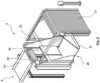
- the Figure 5 illustrates an exemplary embodiment of a conveyor line 2, which in its transport direction (see arrow direction) has a feed conveyor 13 which is arranged lower relative to the withdrawal conveyor 3, following the discharge conveyor 3, via which the sorted piece goods are fed to the filling station 4.
- the feed conveyor 13 has on its shoulder 14 between the discharge conveyor 3 and the feed conveyor 13 a taper 15 of the width of the conveyor section 2 with a starting slope 16, so that piece goods falling from the discharge conveyor 3 via the shoulder 14 onto the feed conveyor 13 are guided along the starting slope 16 becomes.
- the feed speed of the discharge conveyor 3 can be 0.6 m/s, while the feed speed of the feed conveyor 13 can be 1.2 m/s.
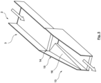
- the Figure 6 describes an exemplary embodiment of a filling station 4.
- This essentially has a frame formed from profiles, which has drive means in the head area analogous to a passenger elevator, with which a shaft 5 can be displaced in the vertical direction.
- the shaft 5 in turn has a wall element on three vertical outer sides and a side that is open over the entire vertical height.
- the shaft 5 On one underside, has a closable opening 7, which can be opened and closed again via a flap, here a two-part flap 12.
- the two partial flaps of the flap element 12 can be locked in almost any position between a completely open and a completely closed position via an actuator 11, so that the opening cross section of the opening 7 can be adjusted to the extent that the piece goods flow out of the shaft gently and continuously a container (not shown) can be achieved.
- the filling station is designed to reduce the height of the piece goods falling in order to prevent damage as much as possible.
- the filling station is designed to reduce the height of the piece goods falling in order to prevent damage as much as possible.
- they can be built more compactly, since the filling function for a terminal bank can be centralized from several buffer stores.
- the basic idea is a lowerable shaft that is lowered into a container provided synchronously with the bulk flow of piece goods on the conveyor line.
- the shaft 5 is closed on three sides.
- the open fourth side is closed above the container by a solid side wall. Inside the container, the fourth side remains open.
- the shaft 5 is slowly opened at the bottom.
- the shaft is raised to such an extent that the flaps 12 can be closed without interrupting the bulk flow of piece goods that may follow.
- a filling station can be used, for example, on a welding frame made of hollow profiles with an attached frame, at the upper end of which two drums, each with a rotary drive and a belt, are attached.
- Each belt can be unwound and wound up using the drives.
- the belts can be lengthened, i.e. lowered downwards, shortened, i.e. wound up, or, if two drives rotate in the same direction, rolled over.
- the straps each have an opening at one point, which is used to hand over the items to the letter container trolley.
- a sorting loop 8 which is designed, for example, in the form of a cross-belt sorter, sorts piece goods 200 into buffer 1.
- the buffers 1 have a fill level sensor, for example a light barrier sensor. After at least one of the buffer stores 1 has reached the intended filling level, for example a maximum filling level, a closable opening 7 at the lower end of the relevant buffer store 1 can be opened by operating a flap 12. Due to the known filling level of the piece goods 200 in the intermediate storage 1, when the flap 12 is opened, a continuous volume flow 200 with a certain total volume can be deposited on the conveying element 2, in particular on the discharge conveyor 3 of the conveying element 2, in a defined manner. To achieve the continuous volume flow, the flap can be opened gradually or continuously, so that a continuous volume flow of piece goods flows from the intermediate storage onto the discharge conveyor 3.
- the discharge conveyor transports the piece goods 200 placed on it to a feed conveyor 13, with which the piece goods 200 are filled into a shaft 5 of a filling station 4 in the form of the continuous volume flow 200.
- the filling is carried out in such a way that the height of the piece goods 200 falling into the shaft 5 is kept to a minimum. This is illustrated in steps 2 to 4. Accordingly, when the shaft 5 is filled with the piece goods 200, the shaft 5 is lowered continuously, ie at a predetermined lowering speed, into the container 100. Due to the continuous volume flow which is supplied to the shaft 5, it is not necessary to determine whether the shaft 5 is actually filled with piece goods in order to determine a suitable lowering of the shaft 5 into the container.
- the flap 12, which closes the opening 7, can be opened in step 5.
- the maximum immersion depth of the shaft 5 into the container 100 is determined such that it is still possible to open the flap 12 by moving the flap 12 out of the clear opening dimension of the opening 7 downwards, ie in the direction of the bottom of the container 100 . If the flap 12 is not opened abruptly, but rather in a slow and continuous movement, a gentle transfer process between the shaft 5 and the container 100 is still possible despite the remaining height of fall between the bottom of the shaft 5 and the bottom of the container 100. Steps 6 to 8 then illustrate that after opening the flap 12, the shaft 5 can be continuously lifted out of the container 100 at a constant speed, with the piece goods 200 being transferred from shaft 5 into the container 100.
- the flap 12 can be moved back into its closed position in step 9, whereby the shaft 5 is already brought back into its starting position according to step 1 and is therefore ready for refilling with piece goods.
- the filling process can be started again.
- the container 100 is in the present case designed as a roll container.
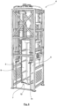
- the Figures 8-11 show a further embodiment of a filling station according to the invention.
- the filling station 4 has a frame with a pivoting device 20 accommodated therein.
- the pivoting device 20 has a contact surface 21 with side walls extending perpendicularly thereto.
- a safety roller shutter can be pushed over the pivoting device 20 and then a container 100 can be pushed in.
- the roller shutter protects the operator from anything falling on his head.
- the safety roller shutter is closed. After filling, the roller shutter moves over the area again to protect the extractor. Then the door leaves 23 can be opened and the container 100 can be pulled out of station 4.
- the pivoting device 20 with the container 100 placed on it can move into the in Figure 10 shown can be pivoted to the vertical inclined position.
- the vertical distance between an upper filling opening of the container 101 and the bottom of the container 100 is compared to its upright orientation (see Figure 11 ) is reduced, so that the height of fall of the piece goods metered from the feed conveyor 13 of the conveyor section 2 into the opening of the container 100 is reduced.
- a flexible and/or adjustable guide element 26 for example a runner and/or a textile material web, can be provided, which forms the transition area between the end of the feed conveyor facing the container 100 13 and the opening of the container 100 bridged.
- the rear wall of the container has a coarse mesh.
- containers 100 are known whose rear wall consists of a perforated sheet metal. The holes are so small that the items can easily slide or slide over the back wall into the container.
- the container 100 can be moved out of the container 100 continuously or step by step by the pivoting device 20 Figure 10 shown to the vertical slanted position towards the in Figure 11 can be pivoted into the upright position shown.
- the container can also be held in the inclined position throughout the entire filling process. The inclined position ensures, on the one hand, the already described minimization of the fall height of the piece goods and, on the other hand, an even filling of the container 100.
- a rear wall protection can be pulled out of the container in a pulse-like manner.
- the Figure 12 shows a filling station which has a piece goods collection point 19, to which the compact piece goods stream (not shown) is fed from a feed conveyor 13 of the conveyor line 2 and from which the piece goods 200 of the piece goods stream are metered into the container 100 by a robot 300.
- the container 100 die Figure 11 After the container 100 die Figure 11 has reached the upright position shown, the container can be removed either via the front roller door 27 or via the rear door wing 23.
- the robot 100 can be any robot, for example an articulated robot.
- the robot 100 can have a gripper, such as a suction gripper, and an image recognition device on its end effector. This enables the robot 100 to randomly orientate the individual items stowed on the piece goods collection point 19, which have any orientation in space and to one another can be grabbed individually and placed in the container or dropped into it, for example, to achieve a high packing density.
- the piece goods collection point 19 can be designed as a widening slide which has a stop at its lower end, for example in the form of a sheet metal edge.
- the piece goods supplied to the piece goods collection point via the conveyor line can be transported down the slide, powered by gravity, along an inclined plane until they come to rest at the stop at the piece goods collection point or at another piece of piece goods.
Landscapes
- Engineering & Computer Science (AREA)
- Mechanical Engineering (AREA)
- Discharge Of Articles From Conveyors (AREA)
Description
Die Erfindung betrifft eine Vorrichtung und ein Verfahren für das Beladen eines Behälters mit sortiertem Stückgut.The invention relates to a device and a method for loading a container with sorted piece goods.
Die
Die
Die
Die
Die aus dem Stand der Technik bekannten Vorrichtungen und Verfahren haben den Nachteil, dass insbesondere in Anwendungsfällen, bei denen nur ein vergleichsweise geringes Stückgutaufkommen besteht, eine nur unzureichende Auslastung der Vorrichtung erreicht wird, sodass insbesondere für Anwendungsfälle, bei denen viele unterschiedliche Sorten sortiert werden müssen, eine entsprechend hohe Anzahl unabhängig voneinander betriebener Vorrichtungen bereitgestellt werden muss, die jeweils die erwähnte, niedrige Auslastung aufweisen. Beispielsweise im Logistikbereich kommt es vor, dass für die Befüllung eines Käfigs ein ganzer Tag benötigt wird, etwa aufgrund eines geringen Aufkommens von Sendungen, welche das dem Käfig zugeordnete Sortierkriterium aufweisen.The devices and methods known from the prior art have the disadvantage that, particularly in applications in which there is only a comparatively small volume of piece goods, only insufficient utilization of the device is achieved, so that in particular for applications in which many different types have to be sorted , a correspondingly high number of independently operated devices must be provided, each of which has the mentioned low utilization. For example, in the logistics sector, it happens that a whole day is needed to fill a cage, for example due to a low volume of shipments that have the sorting criterion assigned to the cage.
Diese Aufgabe wird durch ein Verfahren mit den Merkmalen des Anspruchs 1 gelöst. Der nebengeordnete Anspruch 7 betrifft eine entsprechende Vorrichtung. Vorteilhafte Ausführungsformen sind jeweils Gegenstand der abhängigen Ansprüche.This task is solved by a method with the features of
Demgemäß ist bei einem Verfahren für das Beladen eines Behälters mit sortiertem Stückgut vorgesehen, dass dieses die Schritte aufweist:
- Sortieren von unsortiertem Stückgut in eine Mehrzahl Zwischenspeicher, wobei in jedem Zwischenspeicher sortiertes Stückgut erhalten wird;
- Abführen des sortierten Stückguts von mindestens einer der Zwischenspeicher auf einen Abzugsförderer einer Förderstrecke, mit der das sortierte Stückgut einer Befüllstation zugeführt wird, wobei das sortierte Stückgut als ein kompakter Stückgutstrom über eine bodenseitige Öffnung des Zwischenspeichers auf den Abzugsförderer fällt, wobei das Abführen des sortierten Stückguts das sequenzielle Abführen eines ersten sortierten Stückguts aus einem ersten Zwischenspeicher und das Abführen eines zweiten sortierten Stückguts aus einem zweiten Zwischenspeicher aufweist, wobei das erste und das zweite sortierte Stückgut aufeinanderfolgend auf dem Abzugsförderer aufgelegt werden; und
- Sorting unsorted piece goods into a plurality of buffer stores, with sorted piece goods being obtained in each buffer store;
- Discharging the sorted piece goods from at least one of the buffer stores onto a discharge conveyor of a conveyor line with which the sorted piece goods are fed to a filling station, the sorted piece goods falling as a compact stream of piece goods via a bottom opening of the buffer onto the discharge conveyor, the removal of the sorted piece goods the sequential removal of a first sorted piece of goods from a first buffer and the removal of a second sorted piece of goods from a second buffer has, wherein the first and the second sorted piece goods are successively placed on the discharge conveyor; and
Beladen eines zu beladenen Behälters in der Befüllstation mit dem ersten und dem zweiten sortierten Stückgut. Dabei kann entweder
- a. der zu beladene Behälter in einer zur Vertikalen geneigten Position gehalten oder von einer zur Vertikalen geneigten Position in eine aufrechte Position geschwenkt werden, wobei der vertikale Abstand zwischen einer Einfüllöffnung des Behälters und einem Boden des Behälters kontinuierlich oder schrittweise vergrößert wird, oder
- b. ein höhenverstellbarer Schacht der Befüllstation mit dem sortierten Stückgut befüllt und in dem zu beladenen Behälter abgesenkt werden, und wobei das sortierte Stückgut aus dem Schacht in den Behälter entleert wird, wenn der Schacht infolge des Absenkens eine untere Position erreicht hat, oder
- c. der kompakte Stückgutstrom von einem Zuführförderer der Förderstrecke einer Stückgutsammelstelle zugeführt werden, von welcher die Stückgüter des Stückgutstroms von einem Roboter in den Behälter dosiert werden.
- a. the container to be loaded is held in a position inclined to the vertical or pivoted from a position inclined to the vertical into an upright position, the vertical distance between a filling opening of the container and a bottom of the container being continuously or gradually increased, or
- b. a height-adjustable shaft of the filling station is filled with the sorted piece goods and lowered into the container to be loaded, and the sorted piece goods are emptied from the shaft into the container when the shaft has reached a lower position as a result of the lowering, or
- c. the compact piece goods stream is fed from a feed conveyor to the conveyor section of a piece goods collection point, from which the pieces of the piece goods stream are metered into the container by a robot.
Dadurch, dass das unsortierte Stückgut vor dem Beladen des Behälters in einer Mehrzahl Zwischenspeicher vorsortiert wird, welche funktional einem Pufferspeicher entsprechen können, bevor das sortierte Stückgut mit Hilfe der Förderstrecke der Befüllstation für die Befüllung des Schachts oder Behälters bzw. eines Käfigs zugeführt wird, kann eine höhere Auslastung der Befüllstation erreicht werden.The fact that the unsorted piece goods are pre-sorted in a plurality of buffer stores before loading the container, which can functionally correspond to a buffer store, before the sorted piece goods are fed to the filling station for filling the shaft or container or a cage using the conveyor line a higher utilization of the filling station can be achieved.
Beispielsweise im Logistikbereich können abhängig von Packmaßen, Packgewichten, Zieladressen und einer Vielzahl anderer Kriterien eine Vielzahl Zwischenspeichern bereitgestellt sein, welche jeweils bestimmten Sortierkriterien zugewiesen sind. Je nach zugewiesenen Sortierkriterien kann die Befüllung des Zwischenspeichers mehrere Stunden oder sogar Tage andauern. Eine einzige Befüllstation kann erfindungsgemäß ausreichend sein, um eine annähernd beliebig skalierbare Vielzahl von Zwischenspeichern zu bedienen. Insbesondere dann, wenn das Sortieren des unsortierten Stückguts mit Hilfe einer Sortierschleife erfolgt, die im Falle eines gefüllten Zwischenspeichers und zugleich ausgelasteter Befüllstation die Weiterzirkulierung des in dem gefüllten Ziel-Zwischenspeicher nicht ablegbaren Stückguts erlaubt, ist im Grenzfall eine Auslastung der Befüllstation bis zur Vollauslastung denkbar, auch wenn im Anwendungsfall mit einem gewissen Auslastungspuffer gearbeitet werden wird.For example, in the logistics sector, depending on packing dimensions, packing weights, destination addresses and a variety of other criteria, a large number of buffers can be provided, each of which is assigned to specific sorting criteria. Depending on the assigned sorting criteria, filling the cache can take several hours or even days. According to the invention, a single filling station can be sufficient to serve a large number of buffer stores that can be scaled to any extent. Particularly when the unsorted piece goods are sorted with the help of a sorting loop, which in the case of a filled buffer and at the same time a busy filling station Further circulation of the piece goods that cannot be deposited in the filled target buffer storage is permitted, in the limit case it is conceivable that the filling station can be used to full capacity, even if a certain capacity buffer is used in the application.
Um einen gleichmäßigen kompakten Sortiergutstrom auf dem Abzugsförderer zu erzeugen, kann vorgesehen sein, dass die Öffnung, etwa eine Klappe oder eine Falltür mit einstellbarem Öffnungsquerschnitt, stufenweise oder in einer kontinuierlichen Öffnungsbewegung geöffnet wird, um ein gleichmäßiges Herausfallen der Vorsortierung Stückgüter auf den Abzugsförderer zu gewährleisten. Insbesondere kann vorgesehen sein, dass die Öffnung einen Stellantrieb aufweist, mit dem die Öffnung zwischen einer geöffneten Position und einer geschlossenen Position verstellt werden kann, wobei die Öffnung vorzugsweise Zwischenpositionen zwischen einer vollständig geöffneten Position und der Schließposition einnehmen kann.In order to generate a uniform, compact flow of sorted goods on the discharge conveyor, it can be provided that the opening, such as a flap or a trap door with an adjustable opening cross section, is opened gradually or in a continuous opening movement in order to ensure that the pre-sorted piece goods fall out evenly onto the discharge conveyor . In particular, it can be provided that the opening has an actuator with which the opening can be adjusted between an open position and a closed position, wherein the opening can preferably assume intermediate positions between a fully open position and the closed position.
Die Varianten a. und b unterscheiden sich darin, dass sie unterschiedliche technische Lösung für dieselbe Aufgabe der möglichst produktschonenden Ablage der sortierten Stückgüter in dem Behälter schaffen. Dies kann bei beiden Varianten dadurch erreicht werden, dass abhängig von einem Füllstand der Stückgüter in dem Behälter bzw. dem höhenverstellbaren Schacht eine Verschwenkposition des Behälters bzw. eine vertikale Stellposition des Schachts derart nachgeregelt wird, dass die Fallhöhe des zugeführten Stückguts minimiert wird.The variants a. and b differ in that they create different technical solutions for the same task of placing the sorted piece goods in the container in the most gentle way possible. In both variants, this can be achieved by readjusting a pivoting position of the container or a vertical positioning position of the shaft depending on the fill level of the piece goods in the container or the height-adjustable shaft in such a way that the fall height of the supplied piece goods is minimized.
Die Variante a. hat gegenüber der Variante b. den Vorteil, dass die Stückgüter von der Förderstrecke unmittelbar in den zu beladenen Behälter dosiert werden, während bei der Variante b. die Stückgüter von der Förderstrecke zunächst in den höhenverstellbaren Schacht dosiert werden, aus welchem die Stückgüter in den zu beladenen Behälter überführt werden. Die Überführung der Stückgüter aus dem Schacht in den zu beladenen Behälter kann beispielsweise dann erfolgen, wenn der Schacht eine vorgegebene Befüllung erreicht hat, welche einem bevorzugten Füllvolumen des zu beladenen Behälters entsprechen kann.The variant a. has compared to variant b. the advantage that the piece goods are dosed from the conveyor line directly into the container to be loaded, while in variant b. the piece goods are first metered from the conveyor line into the height-adjustable shaft, from which the piece goods are transferred to the container to be loaded. The transfer of the piece goods from the shaft into the container to be loaded can take place, for example, when the shaft has reached a predetermined filling, which can correspond to a preferred filling volume of the container to be loaded.
Sowohl bei der Variante a. als auch bei der Variante b. können die Volumina der Zwischenspeicher einem ganzzahligen Bruchteil des Füllvolumens des zu befüllenden Behälters entsprechen, wobei auch umfasst sein kann, dass die Volumina der Zwischenspeicher dem Füllvolumen des Behälters entsprechen.Both with variant a. as well as variant b. The volumes of the buffers can correspond to an integer fraction of the filling volume of the container to be filled, which can also include the volumes of the buffers corresponding to the filling volume of the container.
In dem Fall a. kann der Behälter abhängig von einem tatsächlichen oder erwarteten Füllstand des Stückguts in dem Behälter aus der zur Vertikalen geneigten Position in die aufrechte Position geschwenkt werden. Der tatsächliche Füllstand des Stückguts in dem Behälter kann mithilfe mindestens eines Füllstandssensors erfasst werden. Der erwartete Füllstand des Stückguts kann anhand bekannter volumetrischer Daten der in den Zwischenspeichern vorgehaltenen Stückgüter zumindest näherungsweise bestimmt werden.In that case a. The container can be pivoted from the position inclined to the vertical into the upright position depending on an actual or expected fill level of the piece goods in the container. The actual fill level of the piece goods in the container can be detected using at least one fill level sensor. The expected fill level of the piece goods can be determined at least approximately based on known volumetric data of the piece goods held in the buffer stores.
Die aufrechte Position kann eine Position des Behälters sein, in welcher eine obere Einfüllöffnung des Behälters einen im Wesentlichen horizontal angeordneten Öffnungsquerschnitt aufweist. Die zu der Vertikalen geneigte Position kann eine Position sein, in welcher der Öffnungsquerschnitt des Behälters einem Zuführförderer der Förderstrecke zugewandt ist.The upright position may be a position of the container in which an upper filling opening of the container has a substantially horizontally arranged opening cross section. The position inclined to the vertical can be a position in which the opening cross section of the container faces a feed conveyor of the conveying line.
Der Behälter kann in dem Fall a. um eine horizontale Achse zwischen der zur Vertikalen geneigten Position und der aufrechten Position verschwenkt werden, welche beabstandet von einem Boden des Behälters und vorzugsweise näher an der Einfüllöffnung des Behälters als an dem Boden des Behälters angeordnet ist, sodass bei dem Verschwenken des Behälters zwischen den beiden genannten Positionen der Boden eine vergleichsweise größere vertikale Verlagerung erfährt als die Einfüllöffnung, wobei vorzugsweise letztere in jeder Verschwenkposition dem Zuführförderer zugewandt ist, um die Zuführung von Stückgut in den Behälter zu ermöglichen.The container can in this case a. about a horizontal axis between the position inclined to the vertical and the upright position, which is spaced from a bottom of the container and preferably closer to the filling opening of the container than to the bottom of the container, so that when the container is pivoted between the two In the positions mentioned above, the bottom experiences a comparatively greater vertical displacement than the filling opening, the latter preferably facing the feed conveyor in each pivoting position in order to enable the feeding of piece goods into the container.
Das Schwenken des Behälters im Fall a. bzw. das Absenken des Schachts im Fall b. kann während des Befüllens des Schachts mit dem sortierten Stückgut erfolgen, derart, dass eine Fallhöhe des in den Behälter bzw. den Schacht gefüllten Stückguts im Wesentlichen konstant gehalten wird. Da insbesondere das möglichst beschädigungsfreie Verladen des Stückguts etwa im Logistikbereich erstrebenswert ist, kann die Fallhöhe auf ein praktikables Minimum reduziert werden.Pivoting the container in case a. or the lowering of the shaft in case b. can take place while the shaft is being filled with the sorted piece goods, such that a fall height of the piece goods filled into the container or the shaft is kept essentially constant. Since it is particularly desirable to load the general cargo with as little damage as possible, for example in the logistics sector, the fall height can be reduced to a practical minimum.
Es kann insbesondere hinreichend sein, dass das Absenken des Schachts im Fall b. mit einer konstanten Geschwindigkeit erfolgt, während die aus dem Stand der Technik bekannten Verfahren und Vorrichtungen stets die Absenkgeschwindigkeit des Schachtes an eine aktuell erfolgende Beladung des Schachts anpassen, da, wie oben ausgeführt, bei den aus dem Stand der Technik bekannten Verfahren und Vorrichtungen die Beladung des Schachts bzw. des Gewichts über mehrere Stunden oder gar Tage verteilt zeitlich stark inhomogen erfolgt. Erfindungsgemäß ist insbesondere nicht zwingend eine Bestimmung der dem Schacht tatsächlich zugeführten Stückgutmenge, insbesondere dessen Volumen, oder eine Bestimmung des tatsächlichen Füllvolumens des Schachtes erforderlich. Da das Volumen der Zwischenspeicher bekannt ist und das Abführen des sortierten Stückguts auf den Abzugsförderer in einem kompakten und kontinuierlichen Strom erfolgen kann, ist gemäß dem erfindungsgemäßen Verfahren der dem Schacht zugeführte Stückgutvolumenstrom zumindest in einer ersten Näherung sehr gut vorhersehbar, sodass der Schacht mit einer vorgegebenen und festen Geschwindigkeit in den zu beladenen Behälter abgesenkt werden kann.In particular, it may be sufficient for the shaft to be lowered in case b. takes place at a constant speed, while the methods and devices known from the prior art always adapt the lowering speed of the shaft to a current loading of the shaft, as above carried out, in the methods and devices known from the prior art, the loading of the shaft or the weight is carried out in a very inhomogeneous manner over several hours or even days. According to the invention, it is not absolutely necessary to determine the quantity of piece goods actually supplied to the shaft, in particular its volume, or to determine the actual filling volume of the shaft. Since the volume of the intermediate storage is known and the removal of the sorted piece goods to the discharge conveyor can take place in a compact and continuous stream, according to the method according to the invention, the volume flow of piece goods fed to the shaft is very well predictable, at least in a first approximation, so that the shaft with a predetermined and can be lowered into the container to be loaded at a fixed speed.
Es ist denkbar, dass die Absenkgeschwindigkeit bzw. die Schwenkgeschwindigkeit abhängig von einem Sortierkriterium des entleerten Zwischenspeichers bestimmt wird. So kann beispielsweise für sperriges Stückgut, welches beim Befüllen des Schachts vermeintlich leichter verkantet, eine höhere Absenkgeschwindigkeit und damit ein höheres in dem Schacht zu befüllendes Volumen bzw. eine höhere Fallhöhe durch eine höhere Absenkgeschwindigkeit des Schachts in den Behälter bereitgestellt sein.It is conceivable that the lowering speed or the pivoting speed is determined depending on a sorting criterion of the emptied buffer. For example, for bulky piece goods, which supposedly tilt more easily when filling the shaft, a higher lowering speed and thus a higher volume to be filled in the shaft or a higher fall height can be provided by a higher lowering speed of the shaft into the container.
Das Sortieren von unsortiertem Stückgut in die Mehrzahl Zwischenspeicher kann das kontinuierliche oder periodische Bestimmen eines Füllstands mindestens eines der Zwischenspeicher aufweisen. Dazu kann Sensorik vorgesehen sein, wie mindestens eine Lichtschranke, mindestens eine Kamera, oder es kann auch eine steuerungstechnische Umsetzung vorgesehen sein, mittels Zählen der Stückgüter und/oder Bestimmung deren Volumen.The sorting of unsorted piece goods into the plurality of buffer stores can include the continuous or periodic determination of a fill level of at least one of the buffer stores. For this purpose, sensors can be provided, such as at least one light barrier, at least one camera, or a control implementation can also be provided by counting the piece goods and/or determining their volume.
Dabei kann vorgesehen sein, dass mit dem Erreichen eines Zielfüllstands des sortierten Stückguts in dem mindestens einen Zwischenspeicher das Abführen des sortierten Stückguts eingeleitet wird. Der Zielfüllstand des sortierten Stückguts in dem mindestens einen Zwischenspeichers kann ein Befüllungsvolumen des betreffenden Zwischenspeichers bestimmen, welches einem ganzzahligen Bruchteil des Volumens des zu befüllenden Behälters, etwa einem Rollenbehälter oder einen Rollenkäfig, entspricht. Beispielsweise können mehrere der Zwischenspeicher oder auch sämtliche der Zwischenspeicher dasselbe Volumen aufweisen. Beispielsweise kann das Volumen des Zwischenspeichers der Hälfte des Volumens des Behälters entsprechen. So werden für die Befüllung des Behälters zwei Zwischenspeicher sequenziell auf den Abzugsförderer der Förderstrecke abgeführt. Dies kann vorzugsweise derart erfolgen, dass ein im Wesentlichen kontinuierlicher Stückgutstrom auf der Förderstrecke ausgebildet wird, wodurch eine entsprechend kontinuierliche Befüllung des höhenverstellbaren Schachts bzw. des geneigten Behälters erreicht wird.It can be provided that when a target filling level of the sorted piece goods is reached in the at least one intermediate store, the removal of the sorted piece goods is initiated. The target fill level of the sorted piece goods in the at least one intermediate store can determine a filling volume of the relevant intermediate store, which corresponds to an integer fraction of the volume of the container to be filled, such as a roller container or a roller cage. For example, several of the buffers or all of the buffers can have the same volume. For example, the volume of the intermediate storage can correspond to half the volume of the container. Become like this To fill the container, two buffers are discharged sequentially onto the discharge conveyor of the conveyor line. This can preferably be done in such a way that a substantially continuous flow of piece goods is formed on the conveyor path, whereby a correspondingly continuous filling of the height-adjustable shaft or the inclined container is achieved.
Das Entleeren kann das Öffnen einer verschließbaren Öffnung an einer Unterseite des Schachts aufweisen, wobei der Schacht während des Öffnens der verschließbaren Öffnung aus der unteren Position in Richtung einer oberen Position angehoben wird. Das Anheben kann in einer kontinuierlichen Bewegung des Schachts erfolgen. Auch das Öffnen der verschließbaren Öffnung kann in einer kontinuierlichen Bewegung eines Verschließelements, beispielsweise einer Klappe, etwa einer zweigeteilten Klappe, erfolgen. Es kann auch vorgesehen sein, dass bei dem Öffnen der verschließbaren Öffnung das Schließelement in einer teilgeöffneten Position gehalten wird, während der Schacht weiter angehoben wird, um ein gleichmäßiges Herausströmen des Stückguts aus dem Schacht in den Behälter zu erreichen. Dabei kann weiterhin vorgesehen sein, dass erst während einer zweiten Hälfte des Entleerungsvorgangs des Stückguts aus dem Schacht in den Behälter das Verschließelement und damit der Öffnungsquerschnitt des Schachtes vollständig geöffnet wird.The emptying may include opening a closable opening at a bottom of the shaft, the shaft being raised from the lower position toward an upper position during the opening of the closable opening. The lifting can take place in a continuous movement of the shaft. The opening of the closable opening can also take place in a continuous movement of a closing element, for example a flap, for example a two-part flap. It can also be provided that when the closable opening is opened, the closing element is held in a partially open position while the shaft is further raised in order to achieve a uniform flow of the piece goods from the shaft into the container. It can further be provided that the closing element and thus the opening cross section of the shaft is only completely opened during a second half of the emptying process of the piece goods from the shaft into the container.
Gemäß einem anderen Aspekt wird eine Vorrichtung zur Durchführung des Verfahrens für die Beladung eines Behälters mit sortiertem Stückgut nach einem der Ansprüche 1 bis 6 beschrieben. Die Vorrichtung weist eine Sortierschleife auf, mit einer Mehrzahl Zwischenspeichern für sortiertes Stückgut. Der Sorter bzw. die Sortierschleife können als ein Cross-Belt-Sorter ausgebildet sein. Die Zwischenspeicher weisen an ihrer Unterseite jeweils eine verschließbare Öffnung auf, beispielsweise eine Klappe und/oder eine Falltür, die dazu eingerichtet ist, in den Zwischenspeichern vorgehaltenes, sortiertes Stückgut schwerkraftgetrieben auf einen Abzugsförderer einer Förderstrecke zwischen den Zwischenspeichern und einer Befüllstation für Behälter abzuführen, wobei das Füllvolumen des Behälters einem Vielfachen und vorzugsweise dem Doppelten des Füllvolumens eines der Zwischenspeicher entspricht. Die Befüllstation kann einen höhenverstellbaren Schacht aufweisen, der zwischen einer oberen Position und einer unteren Position verstellbar ist. Der Schacht kann an seiner Unterseite eine verschließbare Öffnung aufweisen, die dazu eingerichtet ist, von dem Abzugsförderer dem Schacht zugeführtes Stückgut in einen Behälter zu entleeren, wenn der Schacht in einen Behälter eingetaucht ist.According to another aspect, a device for carrying out the method for loading a container with sorted piece goods according to one of
Alternativ zu dem höhenverstellbaren Schacht kann die Befüllstation eine Schwenkeinrichtung für einen Behälter aufweisen, die dazu eingerichtet ist, schrittweise oder kontinuierlich den zu befüllenden Behälter abhängig von einer tatsächlichen oder erwarteten Füllhöhe des Stückguts in dem Behälter aus einer zur Vertikalen geneigten Position in eine aufrechte Position zu schwenken.As an alternative to the height-adjustable shaft, the filling station can have a pivoting device for a container, which is set up to gradually or continuously move the container to be filled from a position inclined to the vertical into an upright position depending on an actual or expected filling level of the piece goods in the container sway.
Weiterhin alternativ kann die Befüllstation eine Stückgutsammelstelle aufweisen, der der kompakte Stückgutstrom von einem Zuführförderer der Förderstrecke zugeführt ist und von welcher die Stückgüter des Stückgutstroms von einem Roboter in den Behälter dosiert sind. Der Roboter kann ein Knickarmroboter sein, der an seinem Endeffektor einen Greifer, beispielsweise einen Sauggreifer, und eine Bilderkennungseinrichtung aufweist. Dies ermöglicht es dem Roboter, die willkürlich orientiert auf der Stückgutsammelstelle angestauten Einzelstückgüter, die eine beliebige Ausrichtung im Raum und zueinander aufweisen können, individuell zu greifen und beispielsweise zur Erzielung einer hohen Packungsdichte in dem Behälter abzulegen. Die Stückgutsammelstelle kann eine Stückgutrutsche aufweisen oder sein, entlang welcher die der Stückgutsammelstelle über die Förderstrecke zugeführten Stückgüter schwerkraftgetrieben entlang einer schiefen Ebene hinuntertransportiert werden, bis sie an einem Anschlag der Stückgutsammelstelle oder an einem anderen Stückgut zur Anlage kommen.Furthermore, as an alternative, the filling station can have a piece goods collection point, to which the compact piece goods stream is fed from a feed conveyor of the conveyor line and from which the pieces of the piece goods stream are metered into the container by a robot. The robot can be an articulated robot that has a gripper, for example a suction gripper, and an image recognition device on its end effector. This enables the robot to individually grab the individual goods that are randomly oriented and stored on the piece goods collection point, which can have any orientation in space and to one another, and to place them in the container, for example, to achieve a high packing density. The general cargo collection point can have or be a general cargo chute along which the general cargo supplied to the general cargo collection point via the conveyor route is transported down by gravity along an inclined plane until they come to rest at a stop at the general cargo collection point or on another general cargo.
Der Schacht kann im Fall b. mit einer Absenkgeschwindigkeit von der oberen Position in die untere Position oder im Fall a. der Behälter mit einer Winkelgeschwindigkeit aus der geneigten Position in die aufrechte Position bewegt sein, die von einem erwarteten Zuführstrom eines Stückguts abhängt. Die Absenkgeschwindigkeit, mit der der Schacht von der oberen Position in die untere Position bewegt ist, kann gemäß v ≤ Q/A bestimmt sein, wobei v die Absenkgeschwindigkeit des Schachts, Q der Zuführstrom des Stückguts und A die Grundfläche des Schachts ist. Wenn das Stückgut als kompakter Bulk-Strom auf den Abzugsförderer aufgebracht wird, insbesondere als ein solcher aus dem Zwischenspeicher auf den Abzugsförderer entleert wird, kann der Zuführstrom des Stückguts als konstant angenommen werden und demgemäß die Absenkgeschwindigkeit eine konstante Geschwindigkeit sein.The shaft can in case b. with a lowering speed from the upper position to the lower position or in case a. the container can be moved from the inclined position to the upright position at an angular velocity which depends on an expected feed flow of a piece of goods. The lowering speed at which the shaft is moved from the upper position to the lower position can be determined according to v ≤ Q/A, where v is the lowering speed of the shaft, Q is the feed flow of the piece goods and A is the base area of the shaft. If the piece goods are applied to the discharge conveyor as a compact bulk flow, in particular as such is emptied from the buffer onto the discharge conveyor, the feed flow of the piece goods can be assumed to be constant and accordingly the lowering speed can be a constant speed.
Die Zwischenspeicher können als eine Speicherrutsche ausgebildet sein, die an ihrer Unterseite die verschließbare Öffnung aufweist. Die Öffnung kann ein einstellbares Schließorgan, beispielsweise eine Klappe mit einstellbarem Klappenwinkel, aufweisen, sodass die Öffnung einen einstellbaren Öffnungsquerschnitt aufweist. Vorzugsweise weist die Speicherrutsche ein Speicherlabyrinth auf, um die kinetische Energie der auf der Speicherrutsche schwerkraftgetriebenen hinuntergleitenden Stückgüter zu verringern.The buffers can be designed as a storage slide that has the closable opening on its underside. The opening can have an adjustable closing element, for example a flap with an adjustable flap angle, so that the opening has an adjustable opening cross section. The storage chute preferably has a storage labyrinth in order to reduce the kinetic energy of the piece goods sliding down the storage chute by gravity.
Die Zwischenspeicher können in Transportrichtung des Abzugsförderers hintereinander angeordnet sein. Die verschließbaren Öffnungen mindestens zweier der Zwischenspeicher können derart angesteuert sein, dass sie sich zeitversetzt öffnen, so dass vorzugsweise ein kontinuierlicher Zuführstrom des Stückguts auf den Abzugsförderer abgeführt und besonders bevorzugt eine Durchmischung des Stückguts aus unterschiedlichen Zwischenspeichern vermieden ist. Eine Lichtschranke kann einen Erfassungsbereich oberhalb des Abzugsförderers aufweisen, um festzustellen, dass keine Stückgüter darauf angeordnet sind.The intermediate stores can be arranged one behind the other in the transport direction of the discharge conveyor. The closable openings of at least two of the Intermediate stores can be controlled in such a way that they open with a time delay, so that preferably a continuous feed stream of the piece goods is discharged onto the discharge conveyor and particularly preferably a mixing of the piece goods from different intermediate stores is avoided. A light barrier can have a detection area above the discharge conveyor in order to determine that no piece goods are arranged on it.
Der Schacht kann für das Entleeren des Stückguts in den Behälter dazu eingerichtet sein, in der untersten Position die weitere verschließbare Öffnung des Schachts kontinuierlich oder schrittweise zu öffnen und sich zeitgleich oder danach aus der unteren Position in Richtung der oberen Position zu bewegen.For emptying the piece goods into the container, the shaft can be set up to open the further closable opening of the shaft continuously or gradually in the lowest position and to move at the same time or afterwards from the lower position towards the upper position.
Der Schacht kann an mindestens drei von vier Vertikalseiten von vertikalen Seitenwänden verschlossen sein. Vorzugsweise kann eine der drei vertikalen Seitenwände an ihrem oberen Ende eine Einfüllöffnung für Stückgut aufweisen. Vorzugsweise ist eine der vier Vertikalseiten offen, beispielsweise ohne eine vertikale Seitenwand ausgebildet.The shaft can be closed by vertical side walls on at least three of four vertical sides. Preferably, one of the three vertical side walls can have a filling opening for piece goods at its upper end. Preferably one of the four vertical sides is open, for example designed without a vertical side wall.
Alternativ kann der Schacht ein Rahmengestell aus Horizontal- und Vertikalstreben sein, vorzugsweise daraus bestehen, wobei mindestens eine und vorzugsweise sämtliche vertikalen Seiten des Rahmengestells offen sind.Alternatively, the shaft can be, preferably consist of, a frame made of horizontal and vertical struts, with at least one and preferably all vertical sides of the frame being open.
An einem unteren Ende mindestens einer von zwei gegenüberliegend angeordneter vertikaler Seitenwände der drei vertikalen Seitenwände kann eine über einen Stellantrieb angetriebene Klappe für das Öffnen und Schließen der weiteren verschließbaren Öffnung angeordnet sein. Der Stellantrieb kann dazu eingerichtet sein, die Öffnung, etwa eine Klappe, zwischen einer offenen Position und einer Schließposition zu bewegen, wobei vorzugsweise der Stellantrieb weiterhin dazu eingerichtet ist, die Klappe auf mindestens eine Zwischenposition zwischen der Schließposition und der Offenposition festzulegen.A flap driven via an actuator for opening and closing the further closable opening can be arranged at a lower end of at least one of two oppositely arranged vertical side walls of the three vertical side walls. The actuator can be configured to move the opening, such as a flap, between an open position and a closed position, wherein preferably the actuator is further configured to fix the flap to at least one intermediate position between the closed position and the open position.
Die Förderstrecke kann in Transportrichtung nachfolgend zu dem Abzugsförderer einen relativ zu dem Abzugsförderer tiefer angeordneten Zuführförderer aufweisen, über den das sortierte Stückgut der Befüllstation zugeführt ist. Der Zuführförderer kann an einem Absatz zwischen dem Abzugsförderer und dem Zuführförderer eine Verjüngung der Breite der Förderstrecke mit einer Anlaufschräge aufweisen, sodass von dem Abzugsförderer über den Absatz auf den Zuführförderer fallendes Stückgut entlang der Anlaufschräge geführt ist. Damit kann eine Kompaktierung des Stückgutstroms erreicht werden, indem der Stückgutstrom an der Anlaufschräge nach Art eines Pflugs aufgetürmt wird.In the transport direction, the conveyor section can have a feed conveyor arranged lower than the withdrawal conveyor in the transport direction, via which the sorted piece goods are fed to the filling station. The feed conveyor can be at a shoulder between the discharge conveyor and the feed conveyor Tapering of the width of the conveyor section with a starting slope, so that piece goods falling from the discharge conveyor over the shoulder onto the feed conveyor are guided along the starting slope. This allows the flow of piece goods to be compacted by piling up the flow of piece goods on the approach slope in the manner of a plow.
Die Zwischenspeicher am Sorter bzw. an der Sortierschleife können als geschlossene Rutschen parallel zum Verlauf des Sorters bzw. der Sortierschleife ausgebildet sein. Das Abführen des sortierten Stückguts aus den Zwischenspeichern kann mit Hilfe von Sortierrutschen erfolgen, die gegen die Sorter-Laufrichtung geneigt sind. So wird die Ausschleusenergie durch Abbremsen des Stückguts abgebaut.The buffers on the sorter or on the sorting loop can be designed as closed chutes parallel to the course of the sorter or the sorting loop. The sorted cargo can be removed from the intermediate storage with the help of sorting chutes that are inclined against the direction of travel of the sorter. In this way, the discharge energy is reduced by braking the piece goods.
Im Fall a. kann die Schwenkeinrichtung eine Aufstandsfläche für den Behälter sowie eine sich senkrecht dazu erstreckende Begrenzungswand, etwa eine Rückwand aufweisen, an der der Behälter anliegt und/oder abgestützt ist, wenn der Behälter von der Schwenkeinrichtung in der zur Vertikalen verschwenkten Position positioniert ist. Eine Schwenkachse der Schwenkeinrichtung, um welche die Aufstandsfläche mit der mindestens einen Begrenzungswand verschwenkt wird, kann sich parallel zu der betreffenden Begrenzungswand erstrecken, an welcher der Behälter anliegt und/oder abgestützt ist. Die Begrenzungswand kann von mindestens einem und vorzugsweise einem Paar gegenläufig verschwenkbarer Türflügel gebildet sein, sodass die Begrenzungswand durch Verschwenken des mindestens einen Türflügels entfernt werden kann, um das Zuführen und Entfernen eines zu befüllenden Behälters zu ermöglichen.In case a. The pivoting device can have a contact surface for the container and a boundary wall extending perpendicular thereto, such as a rear wall, against which the container rests and / or is supported when the container is positioned by the pivoting device in the position pivoted to the vertical. A pivot axis of the pivoting device, about which the contact surface with the at least one boundary wall is pivoted, can extend parallel to the relevant boundary wall on which the container rests and/or is supported. The boundary wall can be formed by at least one and preferably a pair of counter-pivoting door leaves, so that the boundary wall can be removed by pivoting the at least one door leaf to enable the feeding and removal of a container to be filled.
Der Behälter kann beispielsweise ein Rollenbehälter sein und unmittelbar auf die Aufstandsfläche gerollt werden, wenn sich die Aufstandsfläche parallel zu und aufliegend auf einer Oberfläche, beispielsweise einem Fußboden, befindet. Beispielhafte Behälter können sein:
- Rollbehälter mit 3-seitiger Rückwand;
- Rollbehälter mit 4-seitiger Rückwand komplett geschlossen;
- Gitterboxen;
- Briefrollbehälterwagen;
- Europaletten mit Kunststoff- oder Kartonagenaufsatz;
- Einwegpaletten mit Kunststoff- oder Kartonagenaufsatz.
- Roll container with 3-sided rear wall;
- Roll container with 4-sided rear wall completely closed;
- mesh boxes;
- letter trolleys;
- Euro pallets with plastic or cardboard attachments;
- Disposable pallets with plastic or cardboard attachments.
Weitere Einzelheiten der Erfindung werden anhand der nachstehenden Figuren erläutert. Dabei zeigt:
Figur 1- in schematischer Darstellung eine beispielhafte Ausführungsform einer erfindungsgemäßen Vorrichtung;
Figur 2- eine weitere schematische Darstellung einer erfindungsgemäßen Vorrichtung;
Figur 3- einen Vertikalquerschnitt eines Zwischenspeichers parallel zur Transportrichtung der Förderstrecke;
Figur 4- einen Vertikalquerschnitt des Zwischenspeichers nach
Figur 3 senkrecht zur Transportrichtung der Förderstrecke; Figur 5- in perspektivischer Darstellung eine beispielhafte Ausführungsform einer Förderstrecke;
Figur 6- in perspektivischer Darstellung eine beispielhafte Ausführungsform einer Befüllstation;
Figur 7- in schematischer Darstellung die Schrittabfolge eines beispielhaften Verfahrens für das Beladen eines Behälters nach den erfindungsgemäßen Prinzipien;
Figur 8- eine weitere Ausführungsform einer erfindungsgemäßen Befüllstation;
Figur 9- die
Ausführungsform gemäß Figur 8 mit geöffneter Begrenzungswand; - Figur 10
- die Ausführungsform
gemäß den Figuren 8 und9 mit einem darin in zur Vertikalen geneigter Position aufgenommenen Behälter; Figur 11- die Ausführungsform
gemäß den Figuren 8 bis 10 mit einem darin in aufrechter Position aufgenommenem Behälter; und Figur 12- noch eine weitere Ausführungsform einer erfindungsgemäßen Befüllstation.
- Figure 1
- a schematic representation of an exemplary embodiment of a device according to the invention;
- Figure 2
- a further schematic representation of a device according to the invention;
- Figure 3
- a vertical cross section of a buffer store parallel to the transport direction of the conveyor line;
- Figure 4
- a vertical cross section of the buffer
Figure 3 perpendicular to the transport direction of the conveyor line; - Figure 5
- a perspective view of an exemplary embodiment of a conveyor line;
- Figure 6
- a perspective view of an exemplary embodiment of a filling station;
- Figure 7
- a schematic representation of the sequence of steps of an exemplary method for loading a container according to the principles according to the invention;
- Figure 8
- a further embodiment of a filling station according to the invention;
- Figure 9
- the embodiment according to
Figure 8 with the boundary wall open; - Figure 10
- the embodiment according to
Figures 8 and9 with a container received therein in a position inclined to the vertical; - Figure 11
- the embodiment according to
Figures 8 to 10 with a container received therein in an upright position; and - Figure 12
- yet another embodiment of a filling station according to the invention.
Nachdem die Artikel über eine semi-automatische Einschleuseinheit auf den Cross-Belt des Sorters platziert wurden, werden sie entlang des Sorterverlaufs transportiert. In der Logistikanwendung kann eine Erkennung eines Barcodes vorgesehen sein, wobei mit einem 5-Seiten Lesesystem eine Volumenmessung erfolgt. Im Anschluss kann eine Zielanfrage der Sortersteuerung über eine Datenschnittstelle durchgeführt werden. Das Ziel wird an die Sortersteuerung zurückgemeldet und das Stückgut 200, etwa eine Sendung eines Zwischenspeichers 1 zugewiesen. Wenn eine Sendung dem vorgegebene Zwischenspeicher 1 erreicht hat, wird ein Ausschleusvorgang aktiviert, wozu sich der Cross-Belt dreht und die Sendung ausgeschleust wird. Sollte der Zwischenspeicher 1 nicht verfügbar sein, kann der Artikel auf dem Sorter zirkulieren bis der Zwischenspeicher 1 wieder verfügbar ist oder eine weiterer zulässiger Zwischenspeicher 1 für die Sendung erreicht ist.After the items have been placed on the sorter's cross-belt via a semi-automatic insertion unit, they are transported along the sorter path. In the logistics application, barcode recognition can be provided, with a volume measurement being carried out using a 5-page reading system. A target request from the sorter control can then be carried out via a data interface. The destination is reported back to the sorter control and the
Mit Hilfe der Sortierschleife 8 werden die auf der Sortierschleife 8 transportierten Stückgüter 200 selektiv ihren zugewiesenen Zieladressen entsprechenden Zwischenspeichern 1 zugeordnet, insbesondere in diesen abgelegt oder abgeworfen. So können beispielsweise die Stückgüter 200, nachdem sie den Sortierförderer 8 verlassen haben, über ein Kipp-Förderelement in entsprechende Zwischenspeicher 1 sortiert werden. Eine derartige Vorrichtung ist beispielsweise in der
Die Zwischenspeicher 1 können als Speicherrutschen mit einem Speicherlabyrinth 18 ausgebildet sein, welches die beim Hineinfallen des Stückguts 200 in den Zwischenspeicher 1 von dem Stückgut 200 aufgenommene kinetische Energie zumindest teilweise abbaut, sodass ein schonender Einfüllvorgang des Stückguts in den Zwischenspeicher 1 einerseits und andererseits das Abführen des sortierten Stückguts 200 aus den Zwischenspeichern 1 auf die Förderstrecke 2 ebenso schonend erfolgt.The buffer stores 1 can be designed as storage slides with a
In dem Zwischenspeicher 1 kann eine Sensorik (eine Lichtschranke, eine Kamera, oder dergleichen) angeordnet sein, die ein Signal ausgibt, wenn der Zwischenspeicher 1 voll ist. Wenn die Volumina der Stückgüter auf dem Sorter bekannt sind, kann abgeschätzt werden, wann der Zwischenspeicher 1 voll ist, sodass eine tatsächliche Messung eines Befüllungszustands oder zumindest die Erfassung eines vollständig gefüllten Zustands ("voll") entbehrlich sein kann.A sensor system (a light barrier, a camera, or the like) can be arranged in the
Das aus den Volumina der in den Zwischenspeicher 1 sortierten Stückgüter abgeschätzte Füllvolumen des Zwischenspeicher 1 kann insofern unpräzise sein, als dass die Stückgüter aufgrund ihrer Geometrie eine kaum vorhersagbare Packungsdichte beim Befüllen in den Zwischenspeicher 1 in dem Zwischenspeicher 1 einnehmen. Zur Begrenzung dieser Ungenauigkeit kann ein Algorithmus vorgesehen sein, der aus einer Anzahl und den Volumina von Stückgütern, die in einen sensorisch abgetasteten Zwischenspeicher 1 gefüllt wurden und zu einer vollständigen Befüllung des Zwischenspeicher 1 geführt haben, Erfahrungswissen generiert werden, welches als ein Trainingsdatensatz für das Training einer künstlichen Intelligenz verwendet wird, welche anhand der Anzahl und den Volumina von Stückgütern, welche dem Zwischenspeicher 1 zugeführt werden, mit höherer statistischer Wahrscheinlichkeit korrekt auf eine vollständige Befüllung des Zwischenspeichers 1 rückschließen kann.The filling volume of the
So kann etwa vorgesehen sein, dass im Falle einer abgeschätzten 95-prozentigen Befüllung des Zwischenspeicher 1 aus einer Mehrzahl weiterer Stückgüter, die noch auf dem Sorter liegen und bestimmungsgemäß dem Zwischenspeicher 1 zugeführt werden sollen, dasjenige Stückgut dem Zwischenspeicher 1 noch zugeführt werden, welches unter Berücksichtigung seines Volumens nicht zu einer Überfüllung des Zwischenspeicher 1 über 100 % hinaus führen würde. Beispielsweise würde bei zwei Stückgütern auf dem Sorter, von denen eines 3 % des Füllvolumens des Zwischenspeicher 1 einnimmt und das andere 10 % des Füllvolumens des Zwischenspeicher 1 einnimmt, das Stückgut mit dem 3-prozentigen Füllvolumen dem Zwischenspeicher 1 zugeführt werden, während das andere Stückgut mit dem 10-prozentigen Füllvolumen auf dem Sorter verbleibt.For example, it can be provided that in the event of an estimated 95 percent filling of the
Die Zwischenspeicher 1 können jeweils einen Füllstandssensor aufweisen. Der Füllstandssensor kann beispielsweise eine Lichtschranke sein oder eine solche aufweisen. Die Lichtschranke kann beispielsweise an einem oberen Einfüllende des Zwischenspeichers 1 angeordnet sein, sodass bei dauerhafter Unterbrechung der Lichtschranke durch ein das reflektierte Signal unterbrechendes Stückgut ein definierter Füllstand des Zwischenspeichers erreicht ist, beispielsweise eine Voll-Meldung ausgegeben werden kann. Das Volumen des Zwischenspeichers 1 kann einem ganzzahligen Bruchteil des Volumens des Schachts 5 entsprechen.The
So kann beispielsweise vorgesehen sein, dass das Volumen des Schachts gerade dem doppelten Volumen einer der beiden Zwischenspeicher 1 entspricht, wenn die beiden Zwischenspeicher dasselbe Volumen aufweisen. Beim Umfüllen des Stückguts aus den Zwischenspeichern 1 in den Schacht kann daher vorgesehen sein, dass das Volumen in den jeweiligen Zwischenspeichern 1 sequenziell auf den Abführförderer 3 der Förderstrecke 2 überführt wird. Für das Abführen kann an einer Unterseite des Zwischenspeichers 1 je Zwischenspeicher 1 eine verschließbare Öffnung 6, etwa eine Klappe und/oder eine Falltür ausgebildet sein. Die Öffnung 6 kann beispielsweise über eine Klappe, vorzugsweise über eine zweigeteilte Klappe, verschließbar sein. Die Klappe kann in verschiedenen Stellpositionen, d.h. in verschiedenen teilgeöffneten Positionen arretierbar sein, sodass der aus dem Zwischenspeicher 1 auf den Abzugsförderer 3 abströmende Stückgutvolumenstrom einstellbar ist.For example, it can be provided that the volume of the shaft corresponds to twice the volume of one of the two
Durch das sequenzielle Abführen des Stückguts 200 aus mehreren Zwischenspeichern 1 auf den Abzugsförderer 3 kann erreicht werden, dass ein kontinuierlicher und zeitlich konstanter Stückgutvolumenstrom auf dem Abzugsförderer 3 abgelegt und dementsprechend von der Förderstrecke 2 dem Schacht 5 zugeführt wird. Dies wiederum ermöglicht es, dass für eine gleichmäßige Befüllung des Schachts bei möglichst niedriger Fallhöhe des Stückguts in den Schacht 5 bereits eine kontinuierliche Absenkung des Schachts 5 in den Behälter 100 mit einer konstanten Absenkgeschwindigkeit hinreichend ist, um eine schonende Verladung des Stückguts bereitzustellen. Gegenüber den aus dem Stand der Technik bekannten Vorrichtungen zum Beladen von Behältern ist es insbesondere nicht erforderlich, die Stückzahl und/oder das Volumen des von der Förderstrecke 2 in den Schacht 5 beförderten Stückguts zu bestimmen, um davon abhängig kontinuierlich eine jeweils erforderliche Absenkgeschwindigkeit zu bestimmen und nachzuregeln. Die kompakte Beladung der Förderstrecke 2 ermöglicht einerseits konstante Zuführgeschwindigkeiten der Förderstrecke 2 und andererseits konstante Absenkgeschwindigkeiten des Schachts 5 in den Behälter 100, indem dieser mit einem kontinuierlichen und im Wesentlichen konstanten Volumenstrom beschickt wird.By sequentially discharging the
Die
An der Unterseite der Zwischenspeicher 1 ist jeweils eine Klappe 12 angeordnet, die beispielsweise als zweiteilige Klappe ausgebildet sein kann und verschiedene Stellpositionen zwischen einer Schließstellung und einer Offenstellung aufweist, um ein kontinuierliches Herausströmen der Stückgüter auf den Abzugsförderer 3 und damit einen kontinuierlichen Zuführstrom auf den Abzugsförderer 3 auszubilden.A
Die Zwischenspeicher 1 können als geschlossene Rutschen parallel zum Sorterverlauf ausgebildet sein. Mit diesem Rutschenkonzept können mehrere Befüllungsstationen auf dem vorgegebenen Hallengrundriss integriert werden. Die Ausschleusung kann auf Rutschen erfolgen, die gegen die Sorterlaufrichtung geneigt sind. So wird die Ausschleusenergie durch Abbremsen der Sendungen abgebaut. Anschließend rutschen die Sendungen auf Rutschenebenen, die in Sorterlaufrichtung geneigt sind. Der Zwischenspeicher 1 ist unten mit einer zweiteiligen Klappe geschlossen. Die halbseitigen Klappen öffnen elektromotorisch parallel zum Sorterverlauf.The
Die Rutschenführung innerhalb eines Zwischenspeichers 1 ermöglicht eine produktschonende Zwischenpufferung. Die zweiteilige Klappe wird auf Anforderung langsam geöffnet. Die gesammelten Sendungen gleiten als 3D-Bulk auf einen unterhalb parallel zum Sorter angeordneten Abzugsförderer 3, etwa einen Gurtförderer. Je zwei Zwischenspeicher 1 sammeln die Sendungen für einen Rollbehälter. Je ein Zwischenspeicher sammelt die Sendungen für einen Briefbehälterwagen. Das Füllvolumen des Rollenbehälters kann jedoch auch in mehr oder weniger Zwischenspeicher aufgeteilt sein. Beispielsweise kann der Zwischenspeicher dasselbe Volumen wie der Behälter aufweisen. Ebenso kann der Behälter mindestens das dreifache des Volumens eines der Zwischenspeicher aufweisen. Diesbezüglich ist das erfindungsgemäße Konzept nicht eingeschränkt.The slide guide within a
Für die Befüllungsüberwachung und die Füllstandsmessung der Zwischenspeicher 1 kann Sensorik vorgesehen sein. So kann etwa eine Überwachungs-Lichtschranke am Sorterrutschenblech gemeinsam für mehrere Zwischenspeicher 1 vorgesehen sein. Eine Voll-Melde-Lichtschranke kann je Zwischenspeicher 1 vorgesehen sein. Weiterhin kann eine Überwachung der Klappenstellung über die Endlagen des Antriebsmotors der Klappen vorgesehen sein.Sensors can be provided for monitoring the filling and measuring the level of the
Für die Befüllung eines Rollbehälters sind vorzugsweise zwei Zwischenspeicher 1 vorgesehen. Dadurch können die Endstellen kompakter aufgebaut werden und der Staudruck innerhalb einer Endstelle 1 ist reduziert. Durch mindestens zwei physische Endstellen für ein logisches Ziel werden Rezirkulationen auf dem Sorter verringert.Two
Für die Befüllung eines Briefbehälterwagens ist ein Zwischenspeicher 1 vorgesehen. Da der Zwischenspeicher 1 für einen Briefbehälterwagen nur etwa zu einem Drittel befüllt werden muss, ist der Staudruck in der Endstelle niedrig.A
Der Zwischenspeicher 1 weitet sich nach unten konisch auf, um jegliches Verklemmen von Sendungen zu verhindern.The
Die
Die
Die
Die Befüllstation ist dazu konzipiert, die Fallhöhe des Stückguts zu reduzieren, um Beschädigungen möglichst zu verhindern. Zudem können durch die funktionale Trennung der Behälterbefüllung von den Zwischenspeichern diese kompakter gebaut werden, da die Befüllungsfunktion für eine Endstellenbank aus mehreren Zwischenspeichern zentralisiert werden kann.The filling station is designed to reduce the height of the piece goods falling in order to prevent damage as much as possible. In addition, by functionally separating the container filling from the buffer stores, they can be built more compactly, since the filling function for a terminal bank can be centralized from several buffer stores.
Die Grundidee ist dabei ein absenkbarer Schacht, der synchron zum Bulkstrom der Stückgüter auf der Förderstrecke in einen bereitgestellten Behälter abgesenkt wird. Der Schacht 5 ist dreiseitig geschlossen. Die offene vierte Seite wird oberhalb des Behälters durch eine feste Seitenwand geschlossen. Innerhalb des Behälters bleibt die vierte Seite offen. In einer unteren Position, die das Öffnen der Klappen ermöglicht und die Fallhöhe minimiert, wird der Schacht 5 unten langsam geöffnet. Der Schacht wird soweit angehoben, dass die Klappen 12 geschlossen werden können, ohne den ggf. nachlaufenden Bulk-Strom von Stückgütern zu unterbrechen.The basic idea is a lowerable shaft that is lowered into a container provided synchronously with the bulk flow of piece goods on the conveyor line. The
Zur Befüllung von Briefbehälterwagen kann eine Befüllstation zum Einsatz kommen, bei der z.B. an einem Schweißgestell aus Hohlprofilen mit einem aufgesetzten Rahmen, an dessen oberen Ende je zwei Trommeln mit je einem Drehantrieb sowie mit einem Gurt angebracht sind. Jeder Gurt kann durch die Antriebe ab- und aufgewickelt werden. Je nach Drehrichtung der Antriebe können somit die Gurte verlängert, also nach unten abgesenkt, verkürzt, also nach oben aufgewickelt oder, wenn zwei Antriebe in die gleiche Richtung drehen, umgewälzt werden. Die Gurte haben an je einer Stelle eine Öffnung, die dazu genutzt wird, die Sendungen an den Briefbehälterwagen zu übergeben.To fill letter container trolleys, a filling station can be used, for example, on a welding frame made of hollow profiles with an attached frame, at the upper end of which two drums, each with a rotary drive and a belt, are attached. Each belt can be unwound and wound up using the drives. Depending on the direction of rotation of the drives, the belts can be lengthened, i.e. lowered downwards, shortened, i.e. wound up, or, if two drives rotate in the same direction, rolled over. The straps each have an opening at one point, which is used to hand over the items to the letter container trolley.
Der Beladevorgang eines Behälters 100 ist in
Der Abzugsförderer transportiert das auf ihm abgelegte Stückgut 200 zu einem Zuführförderer 13, mit dem das Stückgut 200 in Form des kontinuierlichen Volumenstroms 200 in einen Schacht 5 einer Befüllstation 4 gefüllt wird. Die Befüllung erfolgt derart, dass die Fallhöhe des Stückguts 200 in den Schacht 5 minimal gehalten wird. Dies ist in den Schritten 2 bis 4 veranschaulicht. Demgemäß wird der Schacht 5 bei dem Befüllen des Schachts 5 mit dem Stückgut 200 kontinuierlich, d.h. mit einer vorgegebenen Absenkgeschwindigkeit in den Behälter 100 abgesenkt. Aufgrund des kontinuierlichen Volumenstroms, welcher dem Schacht 5 zugeführt wird, ist es nicht erforderlich, eine tatsächliche Befüllung des Schachts 5 mit Stückgut zu bestimmen, um davon abhängig eine geeignete Absenkung des Schachts 5 in den Behälter zu ermitteln.The discharge conveyor transports the
Es kann vielmehr mit vorgegebenen festen Werten für die Absenkgeschwindigkeit gearbeitet und trotzdem ein schonendes Befüllen des Schachts 5 mit Stückgut 200 erreicht werden.Rather, it is possible to work with predetermined fixed values for the lowering speed and still achieve gentle filling of the
Nachdem in dem Schritt 4 der Schacht 5 eine maximale Eintauchtiefe in den Behälter 100 erreicht hat, kann in dem Schritt 5 die Klappe 12, welche die Öffnung 7 verschließt, geöffnet werden. Wie in der Zusammenschau der
Nachdem in dem Schritt 8 der Schacht 5 zumindest insoweit aus dem Behälter 100 herausgehoben worden ist, dass sämtliches vormals in dem Schacht 5 vorgehaltenes Stückgut 200 in den Behälter 100 umgefüllt wurde, kann in dem Schritt 9 die Klappe 12 wieder in ihre Schließposition überführt werden, wodurch der Schacht 5 zugleich bereits wieder in seine Ausgangsposition gemäß dem Schritt 1 gebracht und damit für die Neubefüllung mit Stückgut bereit ist. Nach dem Austauschen des gefüllten Behälters 100 durch einen leeren Behälter 1 kann der Befüllvorgang erneut begingen. Der Behälter 100 ist vorliegend als Rollbehälter ausgebildet.After the
Die
Eine Sicherheitsrollade kann über die Schwenkeinrichtung 20 geschoben und anschließend ein Behälter 100 hineingeschoben werden. Dabei sichert die Rollade den Bediener davor, dass ihm nichts auf den Kopf fällt. Wenn der Behäter 100 in der Station 4 steht, wird die Sicherheitsrollade geschlossen. Nach dem Befüllen fährt die Rollade wieder über den Bereich um den Entnehmer zu schützen. Dann können die Türflügel 23 geöffnet und der Behälter 100 aus der Station 4 gezogen werden.A safety roller shutter can be pushed over the pivoting
Nachdem also ein (leerer) Behälter 100, beispielsweise ein Rollbehälter, auf die Aufstandsfläche 21 der Schwenkeinrichtung 20 gerollt worden ist, kann die Schwenkeinrichtung 20 mit dem darauf abgestellten Behälter 100 in die in
Wenn der Behälter 100 mit der Schwenkeinrichtung 20 aus der in
Es gibt aber auch Behälter, die einer Gitterbox ähneln. Das heißt die Behälter haben eine Rückwand, die sehr grobmaschig ist und große Löcher haben. Hier würden Produkte nicht über die Rückwand rutschen. Daher kann es erforderlich sein, dass ein flexibles Führungselement Nr.26 vor der Sortierung in den Behälter gelassen wird.But there are also containers that resemble a mesh box. This means that the containers have a back wall that is very coarse-meshed and has large holes. Here products would not slip over the back wall. Therefore, it may be necessary for a No.26 flexible guide to be dropped into the bin prior to sorting.
Während der Stückgutstrom von dem Zuführförderer 13 über die Öffnung des Behälters 100 in den Behälter 100 dosiert wird, kann der Behälter 100 von der Schwenkeinrichtung 20 kontinuierlich oder schrittweise aus der in
Da der Stückgutstrom der Befüllstation 4 in einem kompakten Volumenstrom von der Förderstrecke 2 zugeführt wird, kann der gesamte Befüllvorgang des Behälters 100 und damit der Verschwenkvorgang zwischen den in den
Die
Nachdem der Behälter 100 die
Der Roboter 100 kann ein beliebiger Roboter sein, beispielsweise ein Knickarmroboter. Der Roboter 100 kann an seinem Endeffektor einen Greifer, etwa einen Sauggreifer, und eine Bilderkennungseinrichtung aufweisen. Dies ermöglicht es dem Roboter 100, die willkürlich orientiert auf der Stückgutsammelstelle 19 angestauten Einzelstückgüter, die eine beliebige Ausrichtung im Raum und zueinander aufweisen können, individuell zu greifen und beispielsweise zur Erzielung einer hohen Packungsdichte in dem Behälter abzulegen bzw. dort hinein fallenzulassen.The
Die Stückgutsammelstelle 19 kann als eine sich aufweitende Rutsche ausgebildet sein, die an ihrem unteren Ende einen Anschlag aufweist, beispielsweise in Form einer Blechumkantung. Die der Stückgutsammelstelle über die Förderstrecke zugeführten Stückgüter können über die Rutsche schwerkraftgetrieben entlang einer schiefen Ebene hinuntertransportiert werden, bis sie an dem Anschlag der Stückgutsammelstelle oder an einem anderen Stückgut zur Anlage kommen.The piece
- 11
- ZwischenspeicherCache
- 22
- Förderstreckeconveyor line
- 33
- Abzugsfördererdischarge conveyor
- 44
- BefüllstationFilling station
- 55
- Schachtshaft
- 66
- verschließbare Öffnunglockable opening
- 77
- weitere verschließbare Öffnungfurther lockable opening
- 88th
- SortierschleifeSorting loop
- 99
- SeitenwandSide wall
- 1010
- EinfüllöffnungFilling opening
- 1111
- StellantriebActuator
- 1212
- Klappeflap
- 1313
- ZuführfördererFeed conveyor
- 1414
- AbsatzParagraph
- 1515
- Verjüngungrejuvenation
- 1616
- AnlaufschrägeLead-in slope
- 1717
- Kipp-Förderelement/RutscheTilting conveyor element/slide
- 1818
- SpeicherlabyrinthMemory maze
- 1919
- StückgutsammelstelleGeneral cargo collection point
- 2020
- SchwenkeinrichtungSwivel device
- 2121
- Auftstandsflächecontact area
- 2222
- BegrenzungswandBoundary wall
- 2323
- Türflügeldoor leaf
- 2525
- BodenFloor
- 2626
- FührungselementLeadership element
- 2727
- TorGoal
- 100100
- Behältercontainer
- 200200
- Stückgutgeneral cargo
- 300300
- Roboterrobot
Claims (18)
- A method for loading a container (100) with sorted piece goods (200), the method comprising the steps of:- Sorting unsorted piece goods (200) into a plurality of intermediate stores (1), wherein sorted piece goods (200) are obtained in each intermediate store (1);- Discharging the sorted piece goods (200) from at least one of the intermediate stores (1) onto a discharge conveyor (3) of a conveying line (2), by means of which the sorted piece goods (200) are fed to a filling station (4), the sorted piece goods (200) falling as a compact piece goods stream via a bottom-side opening of the intermediate store (1) onto the discharge conveyor (3), wherein said discharging of the sorted piece goods (200) comprises sequential discharging of a first sorted piece good (200) from a first intermediate storage (1) and discharging of a second sorted piece good (200) from a second intermediate storage (1), wherein the first and the second sorted piece goods (200) are successively placed on the discharge conveyor (3); and- Loading a container (100) to be loaded in the filling station (4) with the first and the second sorted piece goods (200).
- The method according to claim 1, wherein eithera. the container (100) to be loaded is held in a position inclined to the vertical or is pivoted from this position to an upright position, the vertical distance between a filling opening (10) of the container (100) and a bottom (25) of the container (100) being increased continuously or stepwise, orb. a height-adjustable chute (5) of the filling station (4) is filled with the sorted piece goods (200) and lowered into the container (100) to be loaded, and wherein the sorted piece goods (200) are emptied from the chute (5) into the container (100) when the chute (5) has reached a lower position as a result of the lowering, orc. the compact piece goods stream is fed from a feed conveyor (13) of the conveyor line (2) to a piece goods collection point (19), from which the piece goods (200) of the piece goods stream are metered into the container (100) by a robot (300).
- The method according to claim 2, wherein in the case a. the container (100) is pivoted from the position inclined to the vertical to the upright position depending on an actual or expected filling level of the piece goods (200) in the container (100).
- The method according to claim 2 or 3, wherein in case a. pivoting of the container (100) or in case b. lowering of the chute (5) is performed during filling of the chute (5) with the sorted piece goods (200), such that a drop height of the piece goods (200) filled into the container (100) or the chute (5), respectively, is kept substantially constant or minimized.
- The method according to any one of the preceding claims, wherein sorting unsorted piece goods (200) into a plurality of intermediate stores (1) comprises continuously or periodically determining a fill level of at least one of the intermediate stores (1), wherein upon reaching a target fill level of the sorted piece goods (200) in the at least one intermediate store (1), discharging of the sorted piece goods (200) is initiated.
- The method of any one of claims 2 to 5, wherein the emptying comprises opening a closable opening (7) at a bottom side of the chute (5), wherein preferably the chute (5) is lifted from the lower position towards an upper position during the opening of the closable opening (7).
- A device for carrying out the method for loading a container (100) with sorted piece goods (200) according to one of the preceding claims, wherein the device comprises a filling station (4) for containers (100) with at least one container (100), wherein the device further comprises a sorting loop (8) with a plurality of intermediate stores (1) for sorted piece goods (200), each of which comprises a closable opening (6), which is arranged to transfer sorted piece goods (200) stored in the intermediate stores (1) as a compact piece goods flow, driven by gravity, onto a discharge conveyor (3) of a conveyor line (2) between the intermediate stores (1) and the filling station (4), sorted piece goods (200) held in the intermediate stores (1) as a compact piece goods stream onto a discharge conveyor (3) of a conveying section (2) between the intermediate stores (1) and the filling station (4) for containers (100), characterized in that the opening (6) is arranged on the underside of the intermediate stores and the filling volume of the container (100) corresponds to a multiple and preferably twice the filling volume of one of the intermediate stores (1).
- The device of claim 7, wherein the filling station (4) is eithera. a pivoting device (20) for a container (100), which is arranged to hold a container (100) to be filled in a position inclined to the vertical or to pivot the container (100) stepwise or continuously from the position inclined to the vertical to an upright position depending on an actual or expected filling level of the piece goods (200) in the container (100), orb. has a height-adjustable chute (5) which can be adjusted between an upper position and a lower position, and wherein the chute (5) has a closable opening (7) on its underside which is set up to empty piece goods (200) fed to the chute (5) by the discharge conveyor (3) into a container (100) when the chute (5) is immerged in a container (100), orc. a piece goods collecting station (19) to which the compact piece goods stream is fed from a feed conveyor (13) of the conveyor line (2) and from which the piece goods (200) of the piece goods stream are metered into the container (100) by a robot (20).
- The device of claim 8, wherein in case b. the chute (5) is moved from the upper position to the lower position at a lowering speed or in case a. the container (100) is moved from the inclined position to the upright position at an angular speed that depends on an expected feed flow of a piece of material (200) when the container (100) is not maintained in the position inclined to the vertical.
- The device according to any one of claims 7 to 9, in which the intermediate storage means (1) is designed as a storage chute which has the closable opening (6) on its underside, the opening (6) having an adjustable closing member, preferably a flap with an adjustable flap angle, so that the opening (6) has an adjustable opening cross section.
- The device of claim 10, wherein the storage chute comprises a storage maze (18).
- The device according to any one of claims 7 to 11, in which the intermediate stores (1) are arranged one behind the other in the transport direction of the discharge conveyor (3), the closable opening (6) of at least one, preferably at least two, of the intermediate stores (1) being controlled in such a way that they open with a time delay or simultaneously, so that preferably a continuous feed stream of the piece goods (200) is discharged onto the discharge conveyor (3).
- The device according to any one of claims 7 to 12, wherein in the case b. the chute (5) for emptying the piece goods (200) into the container (100) is adapted to open the closable opening (7) of the chute (5) continuously or stepwise in the lowermost position and to move simultaneously or thereafter from the lower position towards the upper position.
- The device according to any one of claims 8 to 13, wherein in the case b. the chute (5) is closed on at least one of four vertical sides by a vertical side wall (9), and wherein preferably one of the vertical side walls (9) has a filling opening (10) for piece goods (200) at its upper end, and wherein preferably one of the four vertical sides is open.
- The device according to any one of claims 8 to 13, wherein the chute (5) is a framework of horizontal and vertical struts, at least one and preferably all vertical sides of the framework being open.
- The device according to any one of claims 8 to 15, wherein a driven flap (12) is arranged at a lower end of the chute for opening and closing the closable opening (7).
- The device according to one of the claims 7 to 16, in which the conveyor line (2) has, downstream in the transport direction from the discharge conveyor (3), a feed conveyor (13) which is arranged lower relative to the discharge conveyor (3) and via which the sorted piece goods (200) are fed to the filling station (4), the feed conveyor (13) having, at a step (14) between the discharge conveyor (3) and the feed conveyor (13), a tapering (15) of the width of the conveying path (2) with a run-up slope (16), so that piece goods (200) falling from the discharge conveyor (3) over the step (14) onto the feed conveyor (13) are guided along the run-up slope (16).
- The device according to any one of claims 8 to 17, wherein in the case a. the pivoting device (20) comprises a support surface (21) for the container (100) and a boundary wall (22) extending perpendicularly thereto, against which the container (100) rests when the container (100) is positioned by the pivoting device (20) in the position pivoted to the vertical.
Priority Applications (1)
| Application Number | Priority Date | Filing Date | Title |
|---|---|---|---|
| EP21159642.4A EP4049949B1 (en) | 2021-02-26 | 2021-02-26 | Device and method for loading a container with sorted items |
Applications Claiming Priority (1)
| Application Number | Priority Date | Filing Date | Title |
|---|---|---|---|
| EP21159642.4A EP4049949B1 (en) | 2021-02-26 | 2021-02-26 | Device and method for loading a container with sorted items |
Publications (3)
| Publication Number | Publication Date |
|---|---|
| EP4049949A1 EP4049949A1 (en) | 2022-08-31 |
| EP4049949C0 EP4049949C0 (en) | 2023-11-15 |
| EP4049949B1 true EP4049949B1 (en) | 2023-11-15 |
Family
ID=74797845
Family Applications (1)
| Application Number | Title | Priority Date | Filing Date |
|---|---|---|---|
| EP21159642.4A Active EP4049949B1 (en) | 2021-02-26 | 2021-02-26 | Device and method for loading a container with sorted items |
Country Status (1)
| Country | Link |
|---|---|
| EP (1) | EP4049949B1 (en) |
Family Cites Families (6)
| Publication number | Priority date | Publication date | Assignee | Title |
|---|---|---|---|---|
| DE19718269A1 (en) | 1997-04-30 | 1998-11-05 | Beumer Maschf Bernhard | Sliding sorting conveyor for one-piece items |
| DE102005006546B4 (en) | 2005-02-14 | 2012-02-09 | Knapp Ag | Device and method for the vertical conveying of conveyed material |
| DE102010060391A1 (en) * | 2010-11-05 | 2012-05-10 | Red Parcel Post Ag | Method for loading general cargo and invitation station |
| FR2972722B1 (en) | 2011-03-14 | 2014-02-21 | Cinetic Sorting S P A | DIRECT SORTING OF PARCELS IN CONTAINERS WITH REDUCTION IN DAMAGE |
| DE102014224404A1 (en) | 2014-11-28 | 2016-06-02 | Leicht Stanzautomation Gmbh | Filling and changing device for filling containers with bulk material |
| CN108698717B (en) * | 2016-03-02 | 2024-03-01 | 柯尔柏供应链有限责任公司 | System and method for automatic bagging of packages |
-
2021
- 2021-02-26 EP EP21159642.4A patent/EP4049949B1/en active Active
Also Published As
| Publication number | Publication date |
|---|---|
| EP4049949A1 (en) | 2022-08-31 |
| EP4049949C0 (en) | 2023-11-15 |
Similar Documents
| Publication | Publication Date | Title |
|---|---|---|
| DE10305847B3 (en) | Sorting device for mail has individual mail items loaded in storage pockets of circulated temporary store before transfer to open mail containers dependent on their destination addresses | |
| DE602004012200T2 (en) | Device for sorting mail in an order | |
| EP1868923B1 (en) | Conveying device comprising at least one slide for piece goods, and method for stacking piece goods in a container | |
| EP1861327B1 (en) | Pile transfer device and method | |
| EP1054741B1 (en) | Installation for sorting flat mail articles | |
| EP1686080A2 (en) | Commissioning area | |
| EP1970868A1 (en) | Device and method for automatically storing freight | |
| EP2493766B1 (en) | Method and apparatus for the controlled emptying of a transport container filled with articles | |
| EP4126719B1 (en) | Method for sorting articles, and sorting device | |
| DE3530624C2 (en) | ||
| EP2907591B1 (en) | Transfer station, reverse vending machine and method for transfer, in particular for returnable deposit bottles | |
| EP0713835B1 (en) | Palletizer | |
| EP4049949B1 (en) | Device and method for loading a container with sorted items | |
| EP1020234B1 (en) | Conveyor for parcel containers | |
| EP3786088A1 (en) | Method and system for sorting storage-unstable sorting pieces | |
| DE202011005493U1 (en) | Vertical shaft conveyor and forklift | |
| DE102004001794B4 (en) | Liegewarensorter | |
| DE102009052345A1 (en) | Automated picking device and method for automated picking of books, media, brochures and similar items | |
| EP0129532B1 (en) | Device for sorting and collecting unit loads, especially sawn timber | |
| EP3441150A1 (en) | Sorting installation with an unloading device | |
| EP4002313A1 (en) | Storage compartment, storage device and method for storing a plurality of individually fed rollable containers, receiving machine | |
| EP4163235A1 (en) | Device for transferring transported goods between two conveyor devices, a conveyor system and a transfer method | |
| WO1997031727A1 (en) | Device and method of selective transfer of items of mail | |
| DE102015218655A1 (en) | Mail sorter | |
| DD264195A1 (en) | APPARATUS FOR FORCED FEEDING, FOR INTERMEDIATE STORAGE, DEHUMIDIFICATION OF FIXED BODIES OF DEFINED DIMENSIONS AND FORM |
Legal Events
| Date | Code | Title | Description |
|---|---|---|---|
| PUAI | Public reference made under article 153(3) epc to a published international application that has entered the european phase |
Free format text: ORIGINAL CODE: 0009012 |
|
| STAA | Information on the status of an ep patent application or granted ep patent |
Free format text: STATUS: REQUEST FOR EXAMINATION WAS MADE |
|
| 17P | Request for examination filed |
Effective date: 20211112 |
|
| AK | Designated contracting states |
Kind code of ref document: A1 Designated state(s): AL AT BE BG CH CY CZ DE DK EE ES FI FR GB GR HR HU IE IS IT LI LT LU LV MC MK MT NL NO PL PT RO RS SE SI SK SM TR |
|
| STAA | Information on the status of an ep patent application or granted ep patent |
Free format text: STATUS: EXAMINATION IS IN PROGRESS |
|
| 17Q | First examination report despatched |
Effective date: 20230127 |
|
| P01 | Opt-out of the competence of the unified patent court (upc) registered |
Effective date: 20230411 |
|
| REG | Reference to a national code |
Ref country code: DE Ref legal event code: R079 Ref document number: 502021001938 Country of ref document: DE Free format text: PREVIOUS MAIN CLASS: B65G0047960000 Ipc: B07C0005360000 Ref country code: DE Ref legal event code: R079 Free format text: PREVIOUS MAIN CLASS: B65G0047960000 Ipc: B07C0005360000 |
|
| GRAP | Despatch of communication of intention to grant a patent |
Free format text: ORIGINAL CODE: EPIDOSNIGR1 |
|
| STAA | Information on the status of an ep patent application or granted ep patent |
Free format text: STATUS: GRANT OF PATENT IS INTENDED |
|
| RIC1 | Information provided on ipc code assigned before grant |
Ipc: B65G 69/16 20060101ALI20230707BHEP Ipc: B65G 47/44 20060101ALI20230707BHEP Ipc: B65G 47/96 20060101ALI20230707BHEP Ipc: B65B 5/10 20060101ALI20230707BHEP Ipc: B07C 5/36 20060101AFI20230707BHEP |
|
| INTG | Intention to grant announced |
Effective date: 20230807 |
|
| GRAS | Grant fee paid |
Free format text: ORIGINAL CODE: EPIDOSNIGR3 |
|
| GRAA | (expected) grant |
Free format text: ORIGINAL CODE: 0009210 |
|
| STAA | Information on the status of an ep patent application or granted ep patent |
Free format text: STATUS: THE PATENT HAS BEEN GRANTED |
|
| AK | Designated contracting states |
Kind code of ref document: B1 Designated state(s): AL AT BE BG CH CY CZ DE DK EE ES FI FR GB GR HR HU IE IS IT LI LT LU LV MC MK MT NL NO PL PT RO RS SE SI SK SM TR |
|
| REG | Reference to a national code |
Ref country code: CH Ref legal event code: EP Ref country code: GB Ref legal event code: FG4D Free format text: NOT ENGLISH |
|
| REG | Reference to a national code |
Ref country code: DE Ref legal event code: R096 Ref document number: 502021001938 Country of ref document: DE |
|
| REG | Reference to a national code |
Ref country code: IE Ref legal event code: FG4D Free format text: LANGUAGE OF EP DOCUMENT: GERMAN |
|
| U01 | Request for unitary effect filed |
Effective date: 20231115 |
|
| U07 | Unitary effect registered |
Designated state(s): AT BE BG DE DK EE FI FR IT LT LU LV MT NL PT SE SI Effective date: 20231121 |
|
| P04 | Withdrawal of opt-out of the competence of the unified patent court (upc) registered |
Effective date: 20231117 |
|
| PG25 | Lapsed in a contracting state [announced via postgrant information from national office to epo] |
Ref country code: GR Free format text: LAPSE BECAUSE OF FAILURE TO SUBMIT A TRANSLATION OF THE DESCRIPTION OR TO PAY THE FEE WITHIN THE PRESCRIBED TIME-LIMIT Effective date: 20240216 |
|
| PG25 | Lapsed in a contracting state [announced via postgrant information from national office to epo] |
Ref country code: IS Free format text: LAPSE BECAUSE OF FAILURE TO SUBMIT A TRANSLATION OF THE DESCRIPTION OR TO PAY THE FEE WITHIN THE PRESCRIBED TIME-LIMIT Effective date: 20240315 |
|
| PG25 | Lapsed in a contracting state [announced via postgrant information from national office to epo] |
Ref country code: ES Free format text: LAPSE BECAUSE OF FAILURE TO SUBMIT A TRANSLATION OF THE DESCRIPTION OR TO PAY THE FEE WITHIN THE PRESCRIBED TIME-LIMIT Effective date: 20231115 |
|
| PG25 | Lapsed in a contracting state [announced via postgrant information from national office to epo] |
Ref country code: IS Free format text: LAPSE BECAUSE OF FAILURE TO SUBMIT A TRANSLATION OF THE DESCRIPTION OR TO PAY THE FEE WITHIN THE PRESCRIBED TIME-LIMIT Effective date: 20240315 Ref country code: GR Free format text: LAPSE BECAUSE OF FAILURE TO SUBMIT A TRANSLATION OF THE DESCRIPTION OR TO PAY THE FEE WITHIN THE PRESCRIBED TIME-LIMIT Effective date: 20240216 Ref country code: ES Free format text: LAPSE BECAUSE OF FAILURE TO SUBMIT A TRANSLATION OF THE DESCRIPTION OR TO PAY THE FEE WITHIN THE PRESCRIBED TIME-LIMIT Effective date: 20231115 |
|
| U21 | Renewal fee paid with penalty [unitary effect] |
Year of fee payment: 4 Effective date: 20240325 |