EP4046741B1 - Method for laser machining of a timepiece component - Google Patents
Method for laser machining of a timepiece component Download PDFInfo
- Publication number
- EP4046741B1 EP4046741B1 EP21158746.4A EP21158746A EP4046741B1 EP 4046741 B1 EP4046741 B1 EP 4046741B1 EP 21158746 A EP21158746 A EP 21158746A EP 4046741 B1 EP4046741 B1 EP 4046741B1
- Authority
- EP
- European Patent Office
- Prior art keywords
- substrate
- laser beam
- incident laser
- incident
- relative
- Prior art date
- Legal status (The legal status is an assumption and is not a legal conclusion. Google has not performed a legal analysis and makes no representation as to the accuracy of the status listed.)
- Active
Links
- 238000000034 method Methods 0.000 title claims description 36
- 238000003754 machining Methods 0.000 title claims description 14
- 239000000758 substrate Substances 0.000 claims description 59
- 239000013598 vector Substances 0.000 claims description 17
- BASFCYQUMIYNBI-UHFFFAOYSA-N platinum Chemical compound [Pt] BASFCYQUMIYNBI-UHFFFAOYSA-N 0.000 claims description 6
- 239000000919 ceramic Substances 0.000 claims description 5
- 239000000463 material Substances 0.000 claims description 5
- 229910001369 Brass Inorganic materials 0.000 claims description 3
- RYGMFSIKBFXOCR-UHFFFAOYSA-N Copper Chemical compound [Cu] RYGMFSIKBFXOCR-UHFFFAOYSA-N 0.000 claims description 3
- 229910000831 Steel Inorganic materials 0.000 claims description 3
- RTAQQCXQSZGOHL-UHFFFAOYSA-N Titanium Chemical compound [Ti] RTAQQCXQSZGOHL-UHFFFAOYSA-N 0.000 claims description 3
- 230000001133 acceleration Effects 0.000 claims description 3
- 239000010951 brass Substances 0.000 claims description 3
- 229910052802 copper Inorganic materials 0.000 claims description 3
- 239000010949 copper Substances 0.000 claims description 3
- PCHJSUWPFVWCPO-UHFFFAOYSA-N gold Chemical compound [Au] PCHJSUWPFVWCPO-UHFFFAOYSA-N 0.000 claims description 3
- 239000010931 gold Substances 0.000 claims description 3
- 229910052737 gold Inorganic materials 0.000 claims description 3
- 229910052697 platinum Inorganic materials 0.000 claims description 3
- 229910001220 stainless steel Inorganic materials 0.000 claims description 3
- 239000010959 steel Substances 0.000 claims description 3
- 239000010936 titanium Substances 0.000 claims description 3
- 229910052719 titanium Inorganic materials 0.000 claims description 3
- WFKWXMTUELFFGS-UHFFFAOYSA-N tungsten Chemical compound [W] WFKWXMTUELFFGS-UHFFFAOYSA-N 0.000 claims description 3
- 229910052721 tungsten Inorganic materials 0.000 claims description 3
- 239000010937 tungsten Substances 0.000 claims description 3
- 229910052751 metal Inorganic materials 0.000 claims description 2
- 239000002184 metal Substances 0.000 claims description 2
- 230000008569 process Effects 0.000 description 10
- 238000010586 diagram Methods 0.000 description 7
- 238000004519 manufacturing process Methods 0.000 description 7
- 230000003287 optical effect Effects 0.000 description 7
- 238000012545 processing Methods 0.000 description 6
- 239000002086 nanomaterial Substances 0.000 description 5
- 238000011084 recovery Methods 0.000 description 5
- 238000003486 chemical etching Methods 0.000 description 4
- 238000004040 coloring Methods 0.000 description 4
- 238000006073 displacement reaction Methods 0.000 description 3
- 230000002093 peripheral effect Effects 0.000 description 3
- 238000012958 reprocessing Methods 0.000 description 3
- 239000011521 glass Substances 0.000 description 2
- 238000013532 laser treatment Methods 0.000 description 2
- 239000000126 substance Substances 0.000 description 2
- 241001080024 Telles Species 0.000 description 1
- 230000009471 action Effects 0.000 description 1
- QVGXLLKOCUKJST-UHFFFAOYSA-N atomic oxygen Chemical compound [O] QVGXLLKOCUKJST-UHFFFAOYSA-N 0.000 description 1
- 230000015572 biosynthetic process Effects 0.000 description 1
- 230000008859 change Effects 0.000 description 1
- 230000000295 complement effect Effects 0.000 description 1
- 230000007547 defect Effects 0.000 description 1
- 230000007613 environmental effect Effects 0.000 description 1
- 238000005530 etching Methods 0.000 description 1
- 239000012467 final product Substances 0.000 description 1
- 238000005542 laser surface treatment Methods 0.000 description 1
- 239000000203 mixture Substances 0.000 description 1
- 229910052760 oxygen Inorganic materials 0.000 description 1
- 239000001301 oxygen Substances 0.000 description 1
- 230000005855 radiation Effects 0.000 description 1
- 230000009467 reduction Effects 0.000 description 1
- 238000011282 treatment Methods 0.000 description 1
Images

Classifications
-
- B—PERFORMING OPERATIONS; TRANSPORTING
- B23—MACHINE TOOLS; METAL-WORKING NOT OTHERWISE PROVIDED FOR
- B23K—SOLDERING OR UNSOLDERING; WELDING; CLADDING OR PLATING BY SOLDERING OR WELDING; CUTTING BY APPLYING HEAT LOCALLY, e.g. FLAME CUTTING; WORKING BY LASER BEAM
- B23K26/00—Working by laser beam, e.g. welding, cutting or boring
- B23K26/36—Removing material
- B23K26/362—Laser etching
-
- B—PERFORMING OPERATIONS; TRANSPORTING
- B23—MACHINE TOOLS; METAL-WORKING NOT OTHERWISE PROVIDED FOR
- B23K—SOLDERING OR UNSOLDERING; WELDING; CLADDING OR PLATING BY SOLDERING OR WELDING; CUTTING BY APPLYING HEAT LOCALLY, e.g. FLAME CUTTING; WORKING BY LASER BEAM
- B23K26/00—Working by laser beam, e.g. welding, cutting or boring
- B23K26/02—Positioning or observing the workpiece, e.g. with respect to the point of impact; Aligning, aiming or focusing the laser beam
- B23K26/06—Shaping the laser beam, e.g. by masks or multi-focusing
- B23K26/062—Shaping the laser beam, e.g. by masks or multi-focusing by direct control of the laser beam
- B23K26/0622—Shaping the laser beam, e.g. by masks or multi-focusing by direct control of the laser beam by shaping pulses
- B23K26/0624—Shaping the laser beam, e.g. by masks or multi-focusing by direct control of the laser beam by shaping pulses using ultrashort pulses, i.e. pulses of 1ns or less
-
- B—PERFORMING OPERATIONS; TRANSPORTING
- B23—MACHINE TOOLS; METAL-WORKING NOT OTHERWISE PROVIDED FOR
- B23K—SOLDERING OR UNSOLDERING; WELDING; CLADDING OR PLATING BY SOLDERING OR WELDING; CUTTING BY APPLYING HEAT LOCALLY, e.g. FLAME CUTTING; WORKING BY LASER BEAM
- B23K26/00—Working by laser beam, e.g. welding, cutting or boring
- B23K26/08—Devices involving relative movement between laser beam and workpiece
- B23K26/082—Scanning systems, i.e. devices involving movement of the laser beam relative to the laser head
-
- B—PERFORMING OPERATIONS; TRANSPORTING
- B44—DECORATIVE ARTS
- B44C—PRODUCING DECORATIVE EFFECTS; MOSAICS; TARSIA WORK; PAPERHANGING
- B44C1/00—Processes, not specifically provided for elsewhere, for producing decorative surface effects
- B44C1/22—Removing surface-material, e.g. by engraving, by etching
- B44C1/228—Removing surface-material, e.g. by engraving, by etching by laser radiation
-
- G—PHYSICS
- G04—HOROLOGY
- G04B—MECHANICALLY-DRIVEN CLOCKS OR WATCHES; MECHANICAL PARTS OF CLOCKS OR WATCHES IN GENERAL; TIME PIECES USING THE POSITION OF THE SUN, MOON OR STARS
- G04B19/00—Indicating the time by visual means
- G04B19/06—Dials
- G04B19/12—Selection of materials for dials or graduations markings
-
- G—PHYSICS
- G04—HOROLOGY
- G04B—MECHANICALLY-DRIVEN CLOCKS OR WATCHES; MECHANICAL PARTS OF CLOCKS OR WATCHES IN GENERAL; TIME PIECES USING THE POSITION OF THE SUN, MOON OR STARS
- G04B37/00—Cases
- G04B37/22—Materials or processes of manufacturing pocket watch or wrist watch cases
-
- G—PHYSICS
- G04—HOROLOGY
- G04D—APPARATUS OR TOOLS SPECIALLY DESIGNED FOR MAKING OR MAINTAINING CLOCKS OR WATCHES
- G04D3/00—Watchmakers' or watch-repairers' machines or tools for working materials
- G04D3/0069—Watchmakers' or watch-repairers' machines or tools for working materials for working with non-mechanical means, e.g. chemical, electrochemical, metallising, vapourising; with electron beams, laser beams
Definitions
- the patent application EP 2825347 A1 describes such a process making it possible to machine a watch component, more particularly to engrave it using a laser beam whose properties simultaneously make it possible to change the coloring of the component on the path of the laser beam.
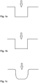
- FIG. 3 of this patent application partially reproduced in the figure 1a appended here, illustrates a cross-sectional view of the substrate etched by the implementation of this process, the shape of the engraving thus obtained being conventional.
- the section of the peripheral sides of the engraving is straight and has a junction with the bottom of the engraving defining a perfect right angle.
- the junction is rarely so clean and perfect.
- the laser source used is typically programmed by means of adjacent or partially superimposed engraving vectors, each of which is delimited by a starting point and an ending point, both located on the periphery of the engraving. to achieve, and is composed of a path to be traveled on the substrate by the incident laser beam emitted in the form of pulses by the laser source, and a series of corresponding impacts of the incident laser beam along this path.
- the relative movement between the incident laser beam and the substrate and the emission of the laser pulses start simultaneously. Due to the relatively high frequency of laser pulses, of the order of a hundred kilohertz, this results in a very high longitudinal recovery rate at the start of the vector, i.e.
- a main aim of the present invention is to propose an alternative process to the processes for engraving watch components by beam.
- laser known from the prior art the method according to the invention allowing the production of an engraving on a watch component having an appearance close to that obtained by the implementation of a chemical attack, and therefore with a high perceived quality .
- the substrate to be treated can be a watch component as such or only a portion of a watch component, either made in one piece with the rest of the component, or attached to the rest of the component before or after the implementation of the process according to the invention, without departing from the scope of the latter.
- the initial period between the start of the relative movement, between the incident laser beam and the substrate, and the first pulse defines a time shift of between 2 and 20 ⁇ s, preferably between 5 and 15 ⁇ s.
- the final period between the last pulse and the end of the relative displacement, between the incident laser beam and the substrate defines a time shift preferably between 5 and 50 ⁇ s, preferably between 10 and 40 ⁇ s.
- the laser source can be programmed to define at least a second vector arranged in such a way that the respective impacts of the first and second vectors have a lateral coverage rate of between 40 and 99%.
- the incident laser beam can be expected to be composed of pulses having an average frequency of between 100 and 1000 kHz.
- the laser source is arranged in such a way that the incident laser beam has a pulse energy of between 1 and 50 ⁇ J.
- the laser source can be arranged in such a way that the speed of the relative movement between the incident laser beam and the substrate is between 500 and 3000 mm/s.
- the substrate comprises one or more of the materials taken from the group comprising: steels, including stainless steels, titanium, copper, brass, gold, platinum, tungsten, ceramics.
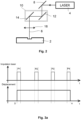
- FIG. 2 represents a simplified block diagram of an example of implementation of a process for machining a watch component according to a preferred embodiment of the present invention.
- the laser beam machining method according to the present invention aims to engrave a substrate 2 for a watch component (not shown in its entirety), this substrate 2 advantageously absorbing at least partially the light of the laser beam at the length d wave of the laser beam used to carry out the machining, preferably between 500 and 1100 nm.
- the substrate may comprise one or more of the materials taken from the group comprising: steels , including stainless steels, titanium, copper, brass, gold, platinum, tungsten, ceramics, by way of non-limiting illustration.
- the substrate 2 can be directly a watch component as such or only a portion of a watch component, either made in one piece with the rest of the component, or attached to the rest of the component, without leaving the framework of the invention.
- the watch component could be directly visible on the corresponding timepiece, by being located outside the box or inside but being visible through a glass, or it can be housed inside the box and be at least partially visible once it is opened.
- a first laser source 4 is used, arranged in relation to an optical device, to define an incident laser beam 6 intended to carry out an engraving on the substrate 2 of the watch component.
- the optical device may comprise, by way of non-limiting illustration, at least one first mirror 8 arranged at the output of the first laser source 4, the latter typically being able to be associated with a galvanometric head 10 comprising a set of additional mirrors, here schematized in the form of two mirrors 12 and 14, making it possible to control the direction of propagation of the incident laser beam 6 and to scan the latter to carry out the engraving on the substrate 2, according to the invention.
- the optical device also advantageously comprises a focusing device 16, shown here schematically in the form of a converging lens to define a desired focusing plane for the incident laser beam 6.
- a mobile support for the substrate 2 to be able to move it relative to the incident laser beam, without departing from the scope of the present invention.
- the first laser source 4 can be associated with the optical device directly inside a multi-axis numerical control machine.
- the numerical control machine When a numerical control machine is used, it is advantageously programmed to control the incident laser beam 6 and its movements appropriately to carry out an engraving of the substrate 2 following a predefined path.
- the numerical control machine typically comprises a control device, for this purpose, taking into account the geometry of the substrate 2 and the engraving to be carried out, and defining the scanning speed of the surface to be treated by the incident laser beam 6 as well as the amplitude of movement of the beam and the generation of laser pulses, so as to obtain the desired engraving.
- the entire engraving on the substrate 2 can be carried out in a single operation.
- the first laser source is chosen in such a way that it defines an incident laser beam 6 composed of light pulses whose duration is of the order of magnitude of a picosecond or femtosecond.
- the optical device is preferably arranged in such a way that the incident laser beam 6 has a focal plane located substantially on the surface of the substrate 2.
- a first laser source 4 can be chosen such that the incident laser beam 6 is composed of pulses having an average frequency of between 100 and 1000 kHz, and such that the latter presents an average power of between 1 and 20 Watts, preferably between 1 and 10 Watts. Furthermore, it can advantageously be provided that the incident laser beam has a pulse energy of between 1 and 50 ⁇ J and that the speed of the relative movement between the incident laser beam and the substrate is between 500 and 3000 mm/s. These different parameters can advantageously be refined to take into account the composition of the substrate.
- the number of pulses to apply per mm 2 to carry out an engraving according to the invention depends in particular on the energy fluence of the laser beam used, its frequency, the scanning distance and the scanning speed. Typically, carrying out a basic engraving on a watch component may require 10 3 to 10 6 pulses per mm 2 , or 10 5 to 10 8 pulses for a pattern of 1 cm 2 .
- the engraving is carried out by adequate programming of the laser source (in its broad sense, that is to say by including the optical device and/or a mobile support making it possible to induce a relative movement between the beam incident and the substrate), in other words by defining at least one vector, preferably a plurality of vectors, each of which is delimited by a starting point and a point arrival and composed of a path to be traveled by the incident laser beam 6 relative to the substrate 2, and a series of impacts of the incident laser beam 6 along the path.
- the laser source in its broad sense, that is to say by including the optical device and/or a mobile support making it possible to induce a relative movement between the beam incident and the substrate
- at least one vector preferably a plurality of vectors, each of which is delimited by a starting point and a point arrival and composed of a path to be traveled by the incident laser beam 6 relative to the substrate 2, and a series of impacts of the incident laser beam 6 along the path.
- the method according to the present invention relates equally to the production of engravings by single passes or by multiple passes, preferably crossed ("cross-hatch") to ensure uniformity of the engraving profile over the entire machined portion.
- FIG 3a represents two schematic diagrams illustrating a typical engraving vector according to the prior art, allowing the production of an engraving like those illustrated on the figures 1a and 1b .
- This engraving vector is delimited by a starting point D and an ending point A, between which the laser beam and the substrate present a relative displacement to define a path followed by the laser beam incident on the substrate.
- the incident laser beam is composed of laser pulses of predefined frequency, here four in number as a schematic example, i.e. pulses P1 to P4 illustrated in the upper diagram of the figure 3a .
- the laser source is programmed so that the incident laser beam moves along the path thus defined, as appears from the lower diagram of the figure 3a .
- the relative displacement between the substrate and the incident laser beam and the laser pulses start at the same time and stop at the same time.
- the Applicant has taken the opposite view of a universal trend in the technical field of laser machining according to which research aims to develop machining processes thanks to which engravings can be produced which approach perfection. in terms of appearance, notably perfectly straight sides. Indeed, the Applicant has carried out research to be able to define specific conditions for laser machining of a component for watchmaking thanks to which the engraving obtained would not be perfect in the industrial sense but would rather resemble the result obtained by implementing a more artisanal process like chemical attack.
- the initial period between the start of the relative movement, between the incident laser beam and the substrate, and the first pulse P1 defines a time shift of between 2 and 20 ⁇ s, preferably between 5 and 15 ⁇ s.
- the final period between the last pulse and the end of the relative movement, between the incident laser beam and the substrate defines a time shift preferably between 5 and 50 ⁇ s, preferably between 10 and 40 ⁇ s.
- the (relative) path of the laser beam incident on the substrate has at least three phases, a first phase of relative acceleration between the incident laser beam and the substrate, a second phase of relative movement at substantially constant speed, and a third relative deceleration phase.
- the laser source is preferably programmed in such a way that the impacts have a substantially constant longitudinal coverage rate during the second phase, between 40 and 99%, the longitudinal coverage rate being variable during the first and third phases.
- the machining process includes at least a second vector
- this is advantageously arranged in such a way that the respective impacts of the first and second vectors have a lateral coverage rate also between 40 and 99%.
- this additional step of processing the engraving makes it possible to modify its micro-structuring, at least on the surface, in particular so that it presents at least one metallic shine, or even so that its coloring is modified so as to present a new predefined coloring.
- a laser with a short or ultra-short pulse duration for example a nanosecond type laser source defining, in association with a optical device not shown, a reprocessing laser beam, acting as a heat source that reacts with environmental oxygen to coat the treated surface with a transparent or semi-transparent oxide layer.
- a reprocessing laser beam acting as a heat source that reacts with environmental oxygen to coat the treated surface with a transparent or semi-transparent oxide layer.
- the oxide layer will have a certain thickness.
- the first set of predefined parameters includes a fluence value of between 0.05 and 0.35 J/cm 2 .
- the first set of predefined parameters includes a longitudinal recovery rate value greater than or equal to 65% and strictly less than 100%, preferably between 65% and 85%.
- the second set of predefined parameters includes a fluence value of between 0.15 and 1 J/cm 2 .
- the second set of predefined parameters includes a longitudinal recovery rate value greater than or equal to 85% and strictly less than 100%, preferably greater than or equal to 90% and less than 99% .
- the third set of predefined parameters predefined parameters to include a fluence value of between 0.05 and 0.35 J/cm 2 .
- the third set of predefined parameters includes a longitudinal recovery rate value greater than or equal to 65% and strictly less than 100%, preferably between 65% and 85%.
- the laser source is arranged to emit laser pulses in "burst" mode, being distributed into groups of successive pulses, with a period of group P, the pulses of a given group being emitted during 20 to 100% of the period P.
- the method comprises an additional step consisting of implementing a fourth laser processing operation aimed at scanning at least part of the curved peripheral wall of the engraving with an incident laser beam, according to a fourth set of predefined parameters, different from the first, second and third sets of predefined parameters and adapted to blacken the peripheral wall by creating microstructures and nanostructures over essentially its entire surface.
- the walls of the engraving are also at least partially blackened, thus giving an improved qualitative appearance to the final product.
- the fourth set of predefined parameters includes a fluence value of between 0.10 and 0.25 J/cm 2 .
- the fourth set of predefined parameters includes a longitudinal recovery rate value greater than or equal to 85% and strictly less than 100%, preferably greater than or equal to 90% and less than 99%.
- the implementation of the present invention is not limited to a watch component forming part of the exterior of a timepiece. Indeed, any watch component can allow the implementation of the present invention to confer a distinctive character to the watch component and therefore to the corresponding time piece. Those skilled in the art will not encounter any particular difficulty in adapting this teaching to the manufacture of watch components or watch movements.
Landscapes
- Physics & Mathematics (AREA)
- Optics & Photonics (AREA)
- Engineering & Computer Science (AREA)
- Plasma & Fusion (AREA)
- Mechanical Engineering (AREA)
- General Physics & Mathematics (AREA)
- Health & Medical Sciences (AREA)
- General Health & Medical Sciences (AREA)
- Toxicology (AREA)
- Manufacturing & Machinery (AREA)
- Laser Beam Processing (AREA)
Description
La présente invention concerne un procédé d'usinage laser d'un substrat pour composant horloger, au moyen d'une source laser destinée à émettre des impulsions de durée égale ou inférieure à la picoseconde et agencée pour définir un faisceau laser incident mobile relativement au substrat et réaliser une gravure sur ce dernier, comportant les étapes consistant à:
- se munir d'un substrat métallique ou en céramique à graver,
- programmer la source laser pour définir au moins un premier vecteur de gravure sur le substrat, délimité par un point de départ et un point d'arrivée, tous deux situés en périphérie de la gravure, et composé d'un trajet à parcourir par le faisceau laser incident relativement au substrat et d'une série d'impacts du faisceau laser incident le long du trajet.
- provide yourself with a metal or ceramic substrate to engrave,
- program the laser source to define at least a first engraving vector on the substrate, delimited by a starting point and an ending point, both located on the periphery of the engraving, and composed of a path to be traveled by the beam incident laser relative to the substrate and a series of impacts of the incident laser beam along the path.
Des nombreux procédés de traitement de composants horlogers par faisceau laser sont déjà connus de l'état de la technique.Numerous processes for processing watch components by laser beam are already known from the state of the art.
Ainsi, par exemple, la demande de brevet
La
Dans la pratique, la jonction est rarement aussi propre et parfaite. En effet, pour réaliser une gravure, la source laser utilisée est typiquement programmée au moyen de vecteurs de gravure adjacents ou partiellement superposés, dont chacun est délimité par un point de départ et un point d'arrivée, tous deux situés en périphérie de la gravure à réaliser, et est composé d'un trajet à parcourir sur le substrat par le faisceau laser incident émis sous forme d'impulsions par la source laser, et d'une série d'impacts correspondants du faisceau laser incident le long de ce trajet. Par défaut, le déplacement relatif entre le faisceau laser incident et le substrat et l'émission des impulsions laser démarrent de manière simultanée. Du fait de la fréquence d'impulsions laser relativement élevée, de l'ordre de la centaine de kilohertz, il en résulte un taux de recouvrement longitudinal très élevé en début de vecteur, soit une superposition importante des premiers impacts et, en pratique, la formation d'une creusure en périphérie de la gravure. Un phénomène similaire intervient en fin de vecteur puisque l'émission des impulsions laser cesse typiquement en même temps que le déplacement du faisceau laser incident, donnant lieu à une superposition importante des derniers impacts sur le substrat. Par conséquent, la forme de la gravure obtenue en pratique ressemble davantage à celle illustrée sur la
Si l'étendue de ces défauts reste limitée, de l'ordre de quelques dizaines de microns, et est donc difficilement détectable à l'oeil nu, elle peut être observée lors d'un examen minutieux, notamment avec une loupe, et convient mal à la réalisation de composants horlogers de haut de gamme dont les acheteurs peuvent être exigeants.If the extent of these defects remains limited, of the order of a few tens of microns, and is therefore difficult to detect with the naked eye, it can be observed during careful examination, in particular with a magnifying glass, and is poorly suited to the creation of high-end watch components of which buyers can be demanding.
On notera par ailleurs que de telles gravures étaient auparavant réalisées par attaque chimique et présentaient alors un profil légèrement différent, comme illustré sur la
Un but principal de la présente invention est de proposer un procédé alternatif aux procédés de gravure de composants horlogers par faisceau laser connus de l'art antérieur, le procédé selon l'invention permettant la réalisation d'une gravure sur un composant horloger présentant une apparence proche de celle obtenue par la mise en oeuvre d'une attaque chimique, et donc avec une qualité perçue élevée.A main aim of the present invention is to propose an alternative process to the processes for engraving watch components by beam. laser known from the prior art, the method according to the invention allowing the production of an engraving on a watch component having an appearance close to that obtained by the implementation of a chemical attack, and therefore with a high perceived quality .
A cet effet, la présente invention concerne plus particulièrement un procédé d'usinage d'un substrat pour composant horloger du type mentionné plus haut, caractérisé par le fait que la source laser est programmée de telle manière
- que la première impulsion associée au premier impact du faisceau laser incident sur le substrat soit émise après que le faisceau laser ait quitté le point de départ pour commencer son déplacement relativement au substrat, et
- que la dernière impulsion associée au dernier impact du faisceau laser incident sur le substrat soit émise avant que le faisceau laser incident ait atteint le point d'arrivée et achevé de se déplacer relativement au substrat.
- that the first pulse associated with the first impact of the incident laser beam on the substrate is emitted after the laser beam has left the starting point to begin its movement relative to the substrate, and
- that the last pulse associated with the last impact of the incident laser beam on the substrate is emitted before the incident laser beam has reached the arrival point and completed moving relative to the substrate.
Le substrat à traiter peut être un composant horloger en tant que tel ou seulement une portion d'un composant horloger, soit réalisé d'une pièce avec le reste du composant, soit rapporté sur le reste du composant avant ou après la mise en oeuvre du procédé selon l'invention, sans sortir du cadre de cette dernière.The substrate to be treated can be a watch component as such or only a portion of a watch component, either made in one piece with the rest of the component, or attached to the rest of the component before or after the implementation of the process according to the invention, without departing from the scope of the latter.
Grâce à ces caractéristiques, il est possible de réaliser une gravure présentant une jonction incurvée entre les flancs et le fond, et donc une apparence similaire à celle réalisée par attaque chimique. Le procédé selon l'invention permet de réaliser une telle gravure avec un contrôle très précis, donc avec une bonne reproductibilité et une excellente résolution, de l'ordre de quelques micromètres.Thanks to these characteristics, it is possible to produce an engraving presenting a curved junction between the sides and the bottom, and therefore an appearance similar to that produced by chemical etching. The method according to the invention makes it possible to carry out such an engraving with very precise control, therefore with good reproducibility and excellent resolution, of the order of a few micrometers.
De manière préférée, la période initiale entre le début du déplacement relatif, entre le faisceau laser incident et le substrat, et la première impulsion définit un décalage temporel compris entre 2 et 20 µs, préférablement entre 5 et 15 µs.Preferably, the initial period between the start of the relative movement, between the incident laser beam and the substrate, and the first pulse defines a time shift of between 2 and 20 µs, preferably between 5 and 15 µs.
Par ailleurs, la période finale entre la dernière impulsion et la fin du déplacement relatif, entre le faisceau laser incident et le substrat, définit un décalage temporel préférablement compris entre 5 et 50 µs, préférablement entre 10 et 40 µs.Furthermore, the final period between the last pulse and the end of the relative displacement, between the incident laser beam and the substrate, defines a time shift preferably between 5 and 50 µs, preferably between 10 and 40 µs.
De manière générale, on peut avantageusement prévoir
- que le trajet du faisceau laser incident présente au moins trois phases, une première phase d'accélération relative entre le faisceau laser incident et le substrat, une deuxième phase de déplacement relatif à vitesse sensiblement constante, et une troisième phase de décélération relative, et
- que la source laser soit programmée de telle manière que les impacts présentent un taux de recouvrement longitudinal sensiblement constant au cours de la deuxième phase, compris entre 40 et 99%, le taux de recouvrement longitudinal étant variable au cours des première et troisième phases.
- that the path of the incident laser beam has at least three phases, a first phase of relative acceleration between the incident laser beam and the substrate, a second phase of relative movement at substantially constant speed, and a third phase of relative deceleration, and
- that the laser source is programmed in such a way that the impacts have a substantially constant longitudinal coverage rate during the second phase, between 40 and 99%, the longitudinal coverage rate being variable during the first and third phases.
De manière générale, on peut prévoir que la source laser soit programmée pour définir au moins un deuxième vecteur agencé de telle manière que les impacts respectifs des premier et deuxième vecteurs présentent un taux de recouvrement latéral compris entre 40 et 99%.Generally speaking, the laser source can be programmed to define at least a second vector arranged in such a way that the respective impacts of the first and second vectors have a lateral coverage rate of between 40 and 99%.
De manière générale, on peut prévoir que le faisceau laser incident soit composé d'impulsions présentant une fréquence moyenne comprise entre 100 et 1000 kHz.Generally speaking, the incident laser beam can be expected to be composed of pulses having an average frequency of between 100 and 1000 kHz.
Par ailleurs, on peut avantageusement prévoir que la source laser soit agencée de telle manière que le faisceau laser incident présente une énergie d'impulsion comprise entre 1 et 50 µJ.Furthermore, it is advantageous for the laser source to be arranged in such a way that the incident laser beam has a pulse energy of between 1 and 50 µJ.
De manière générale, on peut prévoir que la source laser soit agencée de telle manière que la vitesse du déplacement relatif entre le faisceau laser incident et le substrat soit comprise entre 500 et 3000 mm/s.In general, the laser source can be arranged in such a way that the speed of the relative movement between the incident laser beam and the substrate is between 500 and 3000 mm/s.
Selon un mode de réalisation préféré, on peut prévoir que le substrat comporte un ou plusieurs des matériaux pris dans le groupe comprenant: les aciers, y compris les aciers inoxydables, le titane, le cuivre, le laiton, l'or, le platine, le tungstène, les céramiques.According to a preferred embodiment, it can be provided that the substrate comprises one or more of the materials taken from the group comprising: steels, including stainless steels, titanium, copper, brass, gold, platinum, tungsten, ceramics.
D'autres caractéristiques et avantages de la présente invention apparaîtront plus clairement à la lecture de la description détaillée d'un mode de réalisation préféré qui suit, faite en référence aux dessins annexés donnés à titre d'exemple non limitatif et dans lesquels:
- les
figures 1a et 1b représentent des vues en coupe transversale schématiques de gravures obtenues par la mise en oeuvre de procédés selon l'état de la technique, tandis que lafigure 1c représente une vue similaire d'une gravure obtenue par la mise en oeuvre d'un procédé selon un mode de réalisation préféré de la présente invention; - la
figure 2 représente un schéma de principe simplifié d'une source laser permettant la mise en oeuvre du procédé selon la présente invention, et - les
figures 3a et3b représentent des schémas de principe simplifiés illustrant le comportement du faisceau laser effectuant une gravure, respectivement selon l'état de la technique et selon la présente invention.
- THE
figures 1a and 1b represent schematic cross-sectional views of engravings obtained by the implementation of methods according to the state of the art, while thefigure 1c represents a similar view of an engraving obtained by implementing a method according to a preferred embodiment of the present invention; - there
figure 2 represents a simplified block diagram of a laser source allowing the implementation of the method according to the present invention, and - THE
figures 3a And3b represent simplified block diagrams illustrating the behavior of the laser beam carrying out engraving, respectively according to the state of the art and according to the present invention.
La
Plus précisément, le procédé d'usinage par faisceau laser selon la présente invention vise à graver un substrat 2 pour un composant horloger (non représenté dans son intégralité), ce substrat 2 absorbant avantageusement au moins partiellement la lumière du faisceau laser à la longueur d'onde du faisceau laser utilisé pour réaliser l'usinage, préférablement entre 500 et 1100 nm. Ainsi, de manière générale, on pourra mettre en oeuvre le procédé selon l'invention en relation avec toutes sortes de matériaux susceptibles d'être gravés par laser, et le substrat pourra comporter un ou plusieurs des matériaux pris dans le groupe comprenant: les aciers, y compris les aciers inoxydables, le titane, le cuivre, le laiton, l'or, le platine, le tungstène, les céramiques, à titre illustratif non limitatif.More precisely, the laser beam machining method according to the present invention aims to engrave a
Le substrat 2 peut être directement un composant horloger en tant que tel ou seulement une portion d'un composant horloger, soit réalisée d'une pièce avec le reste du composant, soit rapportée sur le reste du composant, sans sortir du cadre de l'invention.The
Par ailleurs, on pourra prévoir que le composant horloger soit directement visible sur la pièce d'horlogerie correspondante, en étant situé à l'extérieur de la boite ou à l'intérieur mais en étant visible au travers d'une glace, ou il peut être logé à l'intérieur de la boite et n'être au moins partiellement visible qu'une fois celle-ci ouverte.Furthermore, we could provide for the watch component to be directly visible on the corresponding timepiece, by being located outside the box or inside but being visible through a glass, or it can be housed inside the box and be at least partially visible once it is opened.
De manière générale, pour réaliser l'usinage selon l'invention, on utilise une première source laser 4 agencée, en relation avec un dispositif optique, pour définir un faisceau laser incident 6 destiné à réaliser une gravure sur le substrat 2 du composant horloger.Generally, to carry out the machining according to the invention, a
Plus précisément, le dispositif optique peut comporter, à titre illustratif non limitatif, au moins un premier miroir 8 agencé en sortie de la première source laser 4, cette dernière pouvant typiquement être associée à une tête galvanométrique 10 comprenant un jeu de miroirs supplémentaires, ici schématisés sous la forme de deux miroirs 12 et 14, permettant de contrôler la direction de propagation du faisceau laser incident 6 et de faire faire un balayage à ce dernier pour réaliser la gravure sur le substrat 2, selon l'invention. Le dispositif optique comporte également, de manière avantageuse, un dispositif de focalisation 16, schématisé ici sous la forme d'une lentille convergente pour définir un plan de focalisation souhaité pour le faisceau laser incident 6. En alternative ou en complément, il est possible de prévoir un support mobile pour le substrat 2, pour pouvoir le déplacer relativement au faisceau laser incident, sans sortir du cadre de la présente invention.More precisely, the optical device may comprise, by way of non-limiting illustration, at least one first mirror 8 arranged at the output of the
De manière avantageuse, la première source laser 4 peut être associée au dispositif optique directement à l'intérieur d'une machine à commande numérique multi-axes.Advantageously, the
Lorsqu'une machine à commande numérique est utilisée, elle est avantageusement programmée pour contrôler le faisceau laser incident 6 et ses déplacements de façon appropriée pour procéder à une gravure du substrat 2 suivant un trajet prédéfini. La machine à commande numérique comporte typiquement un dispositif de pilotage, à cet effet, prenant en compte la géométrie du substrat 2 et de la gravure à réaliser, et définissant la vitesse de balayage de la surface à traiter par le faisceau laser incident 6 ainsi que l'amplitude de mouvement du faisceau et la génération des impulsions laser, de manière à obtenir la gravure souhaitée. De manière avantageuse, l'ensemble de la gravure sur le substrat 2 peut être réalisé en une seule opération.When a numerical control machine is used, it is advantageously programmed to control the
De manière avantageuse, la première source laser est choisie de telle manière qu'elle définisse un faisceau laser incident 6 composé d'impulsions lumineuses dont la durée est de l'ordre de grandeur de la picoseconde ou de la femtoseconde. De plus, le dispositif optique est préférablement agencé de telle manière que le faisceau laser incident 6 présente un plan focal situé sensiblement à la surface du substrat 2.Advantageously, the first laser source is chosen in such a way that it defines an
Typiquement, pour traiter des substrats tels que ceux mentionnés plus haut, on pourra choisir une première source laser 4 telle que le faisceau laser incident 6 soit composé d'impulsions présentant une fréquence moyenne comprise entre 100 et 1000 kHz, et telle que ce dernier présente une puissance moyenne comprise entre 1 et 20 Watts, préférablement entre 1 et 10 Watts. En outre, on peut avantageusement prévoir que le faisceau laser incident présente une énergie d'impulsion comprise entre 1 et 50 µJ et que la vitesse du déplacement relatif entre le faisceau laser incident et le substrat soit comprise entre 500 et 3000 mm/s. Ces différents paramètres peuvent avantageusement être affinés pour prendre en compte la composition du substrat.Typically, to treat substrates such as those mentioned above, a
Le nombre d'impulsions à appliquer par mm2 pour réaliser une gravure selon l'invention dépend notamment de la fluence énergétique du faisceau laser utilisé, de sa fréquence, de la distance de balayage et de la vitesse de balayage. Typiquement, la réalisation d'une gravure basique sur un composant horloger peut nécessiter de 103 à 106 impulsions par mm2, soit de 105 à 108 impulsions pour un motif de 1 cm2.The number of pulses to apply per mm 2 to carry out an engraving according to the invention depends in particular on the energy fluence of the laser beam used, its frequency, the scanning distance and the scanning speed. Typically, carrying out a basic engraving on a watch component may require 10 3 to 10 6 pulses per mm 2 , or 10 5 to 10 8 pulses for a pattern of 1 cm 2 .
De manière préférée, la gravure est réalisée par une programmation adéquate de la source laser (dans son acception large, c'est-à-dire en incluant le dispositif optique et/ou un support mobile permettant d'induire un déplacement relatif entre le faisceau incident et le substrat), autrement dit en définissant au moins un vecteur, préférablement une pluralité de vecteurs, dont chacun est délimité par un point de départ et un point d'arrivée et composé d'un trajet à parcourir par le faisceau laser incident 6 relativement au substrat 2, et d'une série d'impacts du faisceau laser incident 6 le long du trajet.Preferably, the engraving is carried out by adequate programming of the laser source (in its broad sense, that is to say by including the optical device and/or a mobile support making it possible to induce a relative movement between the beam incident and the substrate), in other words by defining at least one vector, preferably a plurality of vectors, each of which is delimited by a starting point and a point arrival and composed of a path to be traveled by the
Le procédé selon la présente invention concerne indifféremment la réalisation de gravures par simples passes ou par passes multiples, préférablement croisées ("cross-hatch") pour assurer une uniformité du profil de gravure sur l'ensemble de la portion usinée.The method according to the present invention relates equally to the production of engravings by single passes or by multiple passes, preferably crossed ("cross-hatch") to ensure uniformity of the engraving profile over the entire machined portion.
La
Ce vecteur de gravure est délimité par un point de départ D et un point d'arrivée A, entre lesquels le faisceau laser et le substrat présentent un déplacement relatif pour définir un trajet suivi par le faisceau laser incident sur le substrat. Le faisceau laser incident est composé d'impulsions laser de fréquence prédéfinie, ici au nombre de quatre à titre d'exemple schématique, soit les impulsions P1 à P4 illustrées sur le diagramme supérieur de la
Typiquement, comme cela ressort de la
La Demanderesse a pris le contre-pied d'une tendance universelle dans le domaine technique de l'usinage laser selon laquelle la recherche vise à mettre au point des procédés d'usinage grâce auxquels des gravures peuvent être réalisées qui s'approchent de la perfection en terme d'aspect, notamment des flancs parfaitement droits. En effet, la Demanderesse a effectué des recherches pour pouvoir définir des conditions spécifiques d'usinage laser d'un composant pour l'horlogerie grâce auxquelles la gravure obtenue ne serait pas parfaite au sens industriel mais ressemblerait plutôt au résultat obtenu par mise en oeuvre d'un procédé plus artisanal comme l'attaque chimique.The Applicant has taken the opposite view of a universal trend in the technical field of laser machining according to which research aims to develop machining processes thanks to which engravings can be produced which approach perfection. in terms of appearance, notably perfectly straight sides. Indeed, the Applicant has carried out research to be able to define specific conditions for laser machining of a component for watchmaking thanks to which the engraving obtained would not be perfect in the industrial sense but would rather resemble the result obtained by implementing a more artisanal process like chemical attack.
Les résultats de ces recherches ressortent de manière schématique de la
On constate de la
De manière préférée, la période initiale entre le début du déplacement relatif, entre le faisceau laser incident et le substrat, et la première impulsion P1 définit un décalage temporel compris entre 2 et 20 µs, préférablement entre 5 et 15 µs. Par ailleurs, la période finale entre la dernière impulsion et la fin du déplacement relatif, entre le faisceau laser incident et le substrat, définit un décalage temporel préférablement compris entre 5 et 50 µs, préférablement entre 10 et 40 µs.Preferably, the initial period between the start of the relative movement, between the incident laser beam and the substrate, and the first pulse P1 defines a time shift of between 2 and 20 µs, preferably between 5 and 15 µs. Furthermore, the final period between the last pulse and the end of the relative movement, between the incident laser beam and the substrate, defines a time shift preferably between 5 and 50 µs, preferably between 10 and 40 µs.
Ainsi, le trajet (relatif) du faisceau laser incident sur le substrat présente au moins trois phases, une première phase d'accélération relative entre le faisceau laser incident et le substrat, une deuxième phase de déplacement relatif à vitesse sensiblement constante, et une troisième phase de décélération relative.Thus, the (relative) path of the laser beam incident on the substrate has at least three phases, a first phase of relative acceleration between the incident laser beam and the substrate, a second phase of relative movement at substantially constant speed, and a third relative deceleration phase.
La source laser est préférablement programmée de telle manière que les impacts présentent un taux de recouvrement longitudinal sensiblement constant au cours de la deuxième phase, compris entre 40 et 99%, le taux de recouvrement longitudinal étant variable au cours des première et troisième phases.The laser source is preferably programmed in such a way that the impacts have a substantially constant longitudinal coverage rate during the second phase, between 40 and 99%, the longitudinal coverage rate being variable during the first and third phases.
Lorsque le procédé d'usinage comporte au moins un deuxième vecteur, celui-ci est avantageusement agencé de telle manière que les impacts respectifs des premier et deuxième vecteurs présentent un taux de recouvrement latéral également compris entre 40 et 99%.When the machining process includes at least a second vector, this is advantageously arranged in such a way that the respective impacts of the first and second vectors have a lateral coverage rate also between 40 and 99%.
De manière avantageuse, mais optionnelle, on peut prévoir une étape supplémentaire de traitement de surface par laser de la gravure réalisée selon la description qui précède. Plus précisément, on peut préférablement prévoir que cette étape supplémentaire de traitement de la gravure permette d'en modifier la micro-structuration, au moins en surface, notamment pour qu'elle présente au moins un éclat métallique, voire pour que sa coloration soit modifiée de manière à présenter une nouvelle coloration prédéfinie.Advantageously, but optionally, it is possible to provide an additional step of laser surface treatment of the engraving produced according to the preceding description. More precisely, we can preferably provide that this additional step of processing the engraving makes it possible to modify its micro-structuring, at least on the surface, in particular so that it presents at least one metallic shine, or even so that its coloring is modified so as to present a new predefined coloring.
Pour réaliser de telles colorations de la gravure, notamment de son fond, on soumet celle-ci à l'action d'un laser à durée d'impulsions brève ou ultrabrève, par exemple une source laser de type nanoseconde définissant, en association avec un dispositif optique non illustré, un faisceau laser de retraitement, agissant comme une source de chaleur qui réagit avec l'oxygène de l'environnement pour revêtir la surface traitée d'une couche d'oxyde transparent ou semi-transparent. En fonction des paramètres du faisceau laser de retraitement tels que sa puissance, sa fréquence, sa largeur d'impulsion, la vitesse de balayage, la fréquence de hachage, le nombre de répétitions ou la distance entre la surface traitée et le plan focal du faisceau laser de retraitement, entre autres, la couche d'oxyde aura une certaine épaisseur. En éclairant ensuite la gravure avec de la lumière blanche, la radiation est réfléchie par les couches supérieures et inférieures d'oxyde. En conséquence, un phénomène d'interférence des rayons réfléchis est perçu par un observateur comme correspondant à une couleur déterminée.To produce such colorings of the engraving, in particular of its background, it is subjected to the action of a laser with a short or ultra-short pulse duration, for example a nanosecond type laser source defining, in association with a optical device not shown, a reprocessing laser beam, acting as a heat source that reacts with environmental oxygen to coat the treated surface with a transparent or semi-transparent oxide layer. Depending on the parameters of the reprocessing laser beam such as its power, frequency, pulse width, scanning speed, chopping frequency, number of repetitions or the distance between the treated surface and the focal plane of the beam laser reprocessing, among others, the oxide layer will have a certain thickness. By then illuminating the etching with white light, the radiation is reflected by the upper and lower oxide layers. Consequently, a phenomenon of interference of the reflected rays is perceived by an observer as corresponding to a specific color.
D'autres procédés de traitement connus pourront être mis en oeuvre, en complément ou en alternative, sans sortir du cadre de l'invention tel que défini par les revendications annexées.Other known treatment methods may be implemented, in addition or as an alternative, without departing from the scope of the invention as defined by the appended claims.
Selon une variante de réalisation préférée, un procédé particulier mis au point par la Demanderesse et visant à noircir la gravure réalisée selon la présente invention peut être mis en oeuvre.According to a preferred embodiment, a particular process developed by the Applicant and aimed at blackening the engraving produced according to the present invention can be implemented.
Ce procédé consiste en un traitement laser de la gravure, au moyen d'une source laser destinée à émettre des impulsions de durées égales ou inférieures à la picoseconde et agencée pour définir un faisceau laser incident mobile relativement à la gravure et réaliser un traitement de cette dernière pour en noircir au moins une portion de manière sélective. Plus précisément, ce procédé de noircissement peut avantageusement comporter les étapes consistant à:
- mettre en oeuvre une première opération de traitement laser visant à balayer la portion à traiter avec un faisceau laser incident, suivant un premier jeu de paramètres prédéfini, adapté pour noircir la portion à traiter en créant des microstructures et des nanostructures sur essentiellement toute sa surface,
- mettre en oeuvre une deuxième opération de traitement laser visant à balayer la portion à traiter avec un faisceau laser incident, suivant un deuxième jeu de paramètres prédéfini, différent du premier jeu de paramètre prédéfini et adapté pour lisser la surface de la portion à traiter, par réduction de la rugosité de la surface de la portion à traiter d'au moins 40%, préférablement d'au moins 50%,
- mettre en oeuvre une troisième opération de traitement laser visant à balayer la portion à traiter avec un faisceau laser incident, suivant un troisième jeu de paramètres prédéfini, similaire au premier jeu de paramètres prédéfini et adapté pour noircir la portion à traiter en recréant des microstructures et des nanostructures sur essentiellement toute sa surface.
- implement a first laser treatment operation aimed at scanning the portion to be treated with an incident laser beam, following a first set of predefined parameters, adapted to blacken the portion to be treated by creating microstructures and nanostructures over essentially its entire surface,
- implement a second laser treatment operation aimed at scanning the portion to be treated with an incident laser beam, according to a second set of predefined parameters, different from the first set of predefined parameters and adapted to smooth the surface of the portion to be treated, by reduction in the roughness of the surface of the portion to be treated by at least 40%, preferably by at least 50%,
- implement a third laser processing operation aimed at scanning the portion to be treated with an incident laser beam, following a third set of predefined parameters, similar to the first set of predefined parameters and adapted to blacken the portion to be treated by recreating microstructures and nanostructures over essentially its entire surface.
De manière avantageuse, on peut prévoir que le premier jeu de paramètres prédéfini inclue une valeur de fluence comprise entre 0.05 et 0.35 J/cm2.Advantageously, it can be provided that the first set of predefined parameters includes a fluence value of between 0.05 and 0.35 J/cm 2 .
De manière alternative ou complémentaire, on peut avantageusement prévoir que le premier jeu de paramètres prédéfini inclue une valeur de taux de recouvrement longitudinal supérieure ou égale à 65% et strictement inférieure à 100%, préférablement comprise entre 65% et 85%.Alternatively or additionally, it can advantageously be provided that the first set of predefined parameters includes a longitudinal recovery rate value greater than or equal to 65% and strictly less than 100%, preferably between 65% and 85%.
De manière alternative ou complémentaire, on peut avantageusement prévoir que le deuxième jeu de paramètres prédéfini inclue une valeur de fluence comprise entre 0.15 et 1 J/cm2.Alternatively or additionally, it can advantageously be provided that the second set of predefined parameters includes a fluence value of between 0.15 and 1 J/cm 2 .
De manière alternative ou complémentaire, on peut avantageusement prévoir que le deuxième jeu de paramètres prédéfini inclue une valeur de taux de recouvrement longitudinal supérieure ou égale à 85% et strictement inférieure à 100%, préférablement supérieure ou égale à 90% et inférieure à 99%.Alternatively or additionally, it can advantageously be provided that the second set of predefined parameters includes a longitudinal recovery rate value greater than or equal to 85% and strictly less than 100%, preferably greater than or equal to 90% and less than 99% .
De manière alternative ou complémentaire, on peut avantageusement prévoir que le troisième jeu de paramètres prédéfini inclue une valeur de fluence comprise entre 0.05 et 0.35 J/cm2.Alternatively or additionally, it is advantageous for the third set of predefined parameters to include a fluence value of between 0.05 and 0.35 J/cm 2 .
De manière alternative ou complémentaire, on peut avantageusement prévoir que le troisième jeu de paramètres prédéfini inclue une valeur de taux de recouvrement longitudinal supérieure ou égale à 65% et strictement inférieure à 100%, préférablement comprise entre 65% et 85%.Alternatively or additionally, it can advantageously be provided that the third set of predefined parameters includes a longitudinal recovery rate value greater than or equal to 65% and strictly less than 100%, preferably between 65% and 85%.
Selon une variante de réalisation préférée, on peut prévoir qu'au cours de la première opération et/ou de la troisième opération, la source laser soit agencée pour émettre des impulsions laser en mode "burst", en étant réparties en des groupes d'impulsions successifs, avec une période de groupe P, les impulsions d'un groupe donné étant émises pendant 20 à 100% de la période P.According to a preferred embodiment, it can be provided that during the first operation and/or the third operation, the laser source is arranged to emit laser pulses in "burst" mode, being distributed into groups of successive pulses, with a period of group P, the pulses of a given group being emitted during 20 to 100% of the period P.
Selon un mode de réalisation préféré, on peut avantageusement prévoir que le procédé comporte une étape supplémentaire consistant à mettre en oeuvre une quatrième opération de traitement laser visant à balayer au moins une partie de la paroi périphérique incurvée de la gravure avec un faisceau laser incident, suivant un quatrième jeu de paramètres prédéfini, différent des premier, deuxième et troisième jeux de paramètres prédéfinis et adapté pour noircir la paroi périphérique en créant des microstructures et des nanostructures sur essentiellement toute sa surface.According to a preferred embodiment, it can advantageously be provided that the method comprises an additional step consisting of implementing a fourth laser processing operation aimed at scanning at least part of the curved peripheral wall of the engraving with an incident laser beam, according to a fourth set of predefined parameters, different from the first, second and third sets of predefined parameters and adapted to blacken the peripheral wall by creating microstructures and nanostructures over essentially its entire surface.
Grâce à cette étape supplémentaire, les parois de la gravure sont également au moins partiellement noircies, conférant ainsi un aspect qualitatif amélioré au produit final.Thanks to this additional step, the walls of the engraving are also at least partially blackened, thus giving an improved qualitative appearance to the final product.
Dans ce cas, on peut avantageusement prévoir que le quatrième jeu de paramètres prédéfini inclue une valeur de fluence comprise entre 0.10 et 0.25 J/cm2.In this case, it can advantageously be provided that the fourth set of predefined parameters includes a fluence value of between 0.10 and 0.25 J/cm 2 .
En outre, on peut avantageusement prévoir dans ce cas, de manière alternative ou complémentaire, que le quatrième jeu de paramètres prédéfini inclue une valeur de taux de recouvrement longitudinal supérieure ou égale à 85% et strictement inférieure à 100%, préférablement supérieure ou égale à 90% et inférieure à 99%.Furthermore, it can advantageously be provided in this case, in an alternative or complementary manner, that the fourth set of predefined parameters includes a longitudinal recovery rate value greater than or equal to 85% and strictly less than 100%, preferably greater than or equal to 90% and less than 99%.
La mise en oeuvre de la présente invention n'est pas limitée à un composant horloger faisant partie de l'habillage d'une pièce d'horlogerie. En effet, tout composant horloger peut permettre la mise en oeuvre de la présente invention pour conférer un caractère distinctif au composant horloger et donc à la pièce d'horlogerie correspondante. L'homme du métier ne rencontrera aucune difficulté particulière pour adapter le présent enseignement à la fabrication de composants horlogers d'habillage ou du mouvement horloger.The implementation of the present invention is not limited to a watch component forming part of the exterior of a timepiece. Indeed, any watch component can allow the implementation of the present invention to confer a distinctive character to the watch component and therefore to the corresponding time piece. Those skilled in the art will not encounter any particular difficulty in adapting this teaching to the manufacture of watch components or watch movements.
La description qui précède s'attache à décrire un mode de réalisation particulier à titre d'illustration non limitative et, l'invention n'est pas limitée à la mise en oeuvre de certaines caractéristiques particulières qui viennent d'être décrites, comme par exemple la nature du composant horloger ou encore la matière dans laquelle il est réalisé.The preceding description attempts to describe a particular embodiment by way of non-limiting illustration and the invention is not limited to the implementation of certain particular characteristics which have just been described, such as for example the nature of the watch component or the material in which it is made.
Claims (10)
- Method of laser machining a substrate (2) for a watch component, by means of a laser source (4, 8, 10) designed to emit pulses (P1, ..., P4) of duration equal to or less than one picosecond and arranged to define an incident laser beam (6) movable relative to said substrate (2) and to perform engraving on the latter, comprising the steps consisting in:- providing a metal or ceramic substrate (2) to be engraved,- programming said laser source (4, 8, 10) to define at least a first engraving vector on said substrate (2), delimited by a starting point (D) and an end point (A), both located at the periphery of the engraving, and consisting of a path to be traversed by said incident laser beam (6) relative to said substrate (2) and of a series of impacts of said incident laser beam (6) on said substrate (2), along said path,characterized in that said laser source (4, 8, 10) is programmed in such a way that the first pulse (P1) associated with the first impact of said incident laser beam (6) on said substrate (2) is emitted after said incident laser beam (6) has left said starting point (D) to begin its movement relative to said substrate (2), and that the last pulse (P4) associated with the last impact of said incident laser beam (6) on said substrate (2) is emitted before said incident laser beam (6) has reached said end point (A) and completed its movement relative to said substrate (2).
- Method according to claim 1, characterized in that the initial period between the start of relative movement, between said incident laser beam (6) and said substrate (2), and said first pulse (P1) defines a time offset of between 2 and 20 µs, preferably between 5 and 15 µs.
- Method according to claim 1 or 2, characterized in that the final period between said last pulse (P4) and the end of relative movement, between said incident laser beam (6) and said substrate (2), defines a time offset of between 5 and 50 µs, preferably between 10 and 40 µs.
- Method according to one of the preceding claims, characterizedin that said path presents at least three phases, a first phase of relative acceleration between said incident laser beam (6) and said substrate (2), a second phase of relative movement at substantially constant speed, and a third phase of relative deceleration, andin that said laser source (4, 8, 10) is programmed in such a way that said impacts present a substantially constant rate of longitudinal overlap during said second phase, of between 40 and 99%, the rate of longitudinal overlap being variable during the first and third phases.
- Method according to one of the preceding claims, characterized in that said laser source (4, 8, 10) is programmed to define at least a second vector arranged in such a way that the respective impacts of said first and second vectors have a lateral overlap rate of between 40 and 99%.
- Method according to one of the preceding claims, characterized in that said incident laser beam (6) is composed of pulses having an average frequency of between 100 and 1000 kHz.
- Method according to one of the preceding claims, characterized in that said incident laser beam (6) has an average power of between 1 and 20 Watts, preferably between 1 and 10 Watts.
- Method according to one of the preceding claims, characterized in that said laser source (4, 8, 10) is arranged in such a way that said incident laser beam (6) has a pulse energy of between 1 and 50 µJ.
- Method according to one of the preceding claims, characterized in that said laser source (4, 8, 10) is arranged in such a way that the speed of relative movement between said incident laser beam (6) and said substrate (2) is between 500 and 3000 mm/s.
- Method according to one of the preceding claims, characterized in that said substrate (2) comprises one or more materials taken from the group comprising: steels, including stainless steels, titanium, copper, brass, gold, platinum, tungsten, ceramics.
Priority Applications (1)
| Application Number | Priority Date | Filing Date | Title |
|---|---|---|---|
| EP21158746.4A EP4046741B1 (en) | 2021-02-23 | 2021-02-23 | Method for laser machining of a timepiece component |
Applications Claiming Priority (1)
| Application Number | Priority Date | Filing Date | Title |
|---|---|---|---|
| EP21158746.4A EP4046741B1 (en) | 2021-02-23 | 2021-02-23 | Method for laser machining of a timepiece component |
Publications (2)
| Publication Number | Publication Date |
|---|---|
| EP4046741A1 EP4046741A1 (en) | 2022-08-24 |
| EP4046741B1 true EP4046741B1 (en) | 2023-11-01 |
Family
ID=74732633
Family Applications (1)
| Application Number | Title | Priority Date | Filing Date |
|---|---|---|---|
| EP21158746.4A Active EP4046741B1 (en) | 2021-02-23 | 2021-02-23 | Method for laser machining of a timepiece component |
Country Status (1)
| Country | Link |
|---|---|
| EP (1) | EP4046741B1 (en) |
Family Cites Families (5)
| Publication number | Priority date | Publication date | Assignee | Title |
|---|---|---|---|---|
| US7259354B2 (en) | 2004-08-04 | 2007-08-21 | Electro Scientific Industries, Inc. | Methods for processing holes by moving precisely timed laser pulses in circular and spiral trajectories |
| WO2013135703A1 (en) * | 2012-03-12 | 2013-09-19 | Rolex S.A. | Method for engraving a timepiece component and timepiece component obtained using such a method |
| WO2014152526A1 (en) | 2013-03-15 | 2014-09-25 | Electro Scientific Industries, Inc. | Laser systems and methods for aod tool settling for aod travel reduction |
| CN111716004B (en) | 2020-06-19 | 2021-08-10 | 西安交通大学 | Femtosecond-nanosecond ultra-pulse laser leveling processing system for ceramic matrix composite material |
| CN112077439B (en) | 2020-09-04 | 2021-06-22 | 西安交通大学 | Method for processing three-dimensional current collector of energy storage device by laser multi-frequency optimization combination |
-
2021
- 2021-02-23 EP EP21158746.4A patent/EP4046741B1/en active Active
Also Published As
| Publication number | Publication date |
|---|---|
| EP4046741A1 (en) | 2022-08-24 |
Similar Documents
| Publication | Publication Date | Title |
|---|---|---|
| EP2825347B1 (en) | Method of etching a watch element | |
| EP3067220B1 (en) | Method for decorating a timepiece and timepiece obtained by such a method | |
| EP3452250B1 (en) | Method and apparatus for joining a substrate and a piece by structuring of the substrate | |
| EP2576127B2 (en) | Process of engraving at least one groove for forming incipient fractures using a optical fibre laser device | |
| EP2674302B1 (en) | Method of producing a coloured motif in the body of a transparent glass object | |
| EP3530476A1 (en) | Treatment of a painted surface using a laser | |
| EP4046741B1 (en) | Method for laser machining of a timepiece component | |
| EP4071558A1 (en) | Method for manufacturing a clock component by surface structuring | |
| CH718373A2 (en) | Laser machining process for a watch component. | |
| EP4046817B1 (en) | Method for laser treatment of a timepiece component intended to darken at least one portion | |
| CH718375A2 (en) | Process for the laser treatment of a watch component aimed at blackening at least a portion thereof. | |
| CH717123B1 (en) | Metal marking process for a watch component. | |
| WO2022234155A2 (en) | Method for cutting an amorphous metal alloy sample | |
| CA3133730A1 (en) | Method for creating an iridescent visual effect on the surface of a material, devices for carrying out said method, and part obtained thereby | |
| CH715906A2 (en) | Timepiece component having on its surface a diffraction grating and corresponding manufacturing process. | |
| EP3956095A1 (en) | Method for the creation of an iridescent effect on the surface of a material, and devices for carrying out said method | |
| EP3820644B1 (en) | Process of nanostructuring the surface of a material by laser | |
| CH712016B1 (en) | A method of manufacturing an optical element for a timepiece. | |
| CH715981A2 (en) | Method for marking a sapphire watch crystal. | |
| EP4315157A1 (en) | Method and device for forming an image on or in a part | |
| WO2011045260A1 (en) | Method for the micro-deformation of a front face of a thin part by means of modifying the rear face or the periphery of the part | |
| EP4132740A1 (en) | Laser turning system, laser turning method, and part obtained by using such a system | |
| Wlodarczyk et al. | The impact of graphite coating and wavelength on picosecond laser machining of optical glasses | |
| EP4132739A1 (en) | Laser turning system, laser turning method using such a system, and part obtained by such a method | |
| CH718465A2 (en) | Process for manufacturing a ceramic-based watch or jewelery casing part with a structured decor. |
Legal Events
| Date | Code | Title | Description |
|---|---|---|---|
| PUAI | Public reference made under article 153(3) epc to a published international application that has entered the european phase |
Free format text: ORIGINAL CODE: 0009012 |
|
| STAA | Information on the status of an ep patent application or granted ep patent |
Free format text: STATUS: THE APPLICATION HAS BEEN PUBLISHED |
|
| AK | Designated contracting states |
Kind code of ref document: A1 Designated state(s): AL AT BE BG CH CY CZ DE DK EE ES FI FR GB GR HR HU IE IS IT LI LT LU LV MC MK MT NL NO PL PT RO RS SE SI SK SM TR |
|
| STAA | Information on the status of an ep patent application or granted ep patent |
Free format text: STATUS: REQUEST FOR EXAMINATION WAS MADE |
|
| TPAC | Observations filed by third parties |
Free format text: ORIGINAL CODE: EPIDOSNTIPA |
|
| TPAC | Observations filed by third parties |
Free format text: ORIGINAL CODE: EPIDOSNTIPA |
|
| 17P | Request for examination filed |
Effective date: 20230214 |
|
| RBV | Designated contracting states (corrected) |
Designated state(s): AL AT BE BG CH CY CZ DE DK EE ES FI FR GB GR HR HU IE IS IT LI LT LU LV MC MK MT NL NO PL PT RO RS SE SI SK SM TR |
|
| GRAP | Despatch of communication of intention to grant a patent |
Free format text: ORIGINAL CODE: EPIDOSNIGR1 |
|
| STAA | Information on the status of an ep patent application or granted ep patent |
Free format text: STATUS: GRANT OF PATENT IS INTENDED |
|
| INTG | Intention to grant announced |
Effective date: 20230601 |
|
| GRAS | Grant fee paid |
Free format text: ORIGINAL CODE: EPIDOSNIGR3 |
|
| GRAA | (expected) grant |
Free format text: ORIGINAL CODE: 0009210 |
|
| STAA | Information on the status of an ep patent application or granted ep patent |
Free format text: STATUS: THE PATENT HAS BEEN GRANTED |
|
| AK | Designated contracting states |
Kind code of ref document: B1 Designated state(s): AL AT BE BG CH CY CZ DE DK EE ES FI FR GB GR HR HU IE IS IT LI LT LU LV MC MK MT NL NO PL PT RO RS SE SI SK SM TR |
|
| REG | Reference to a national code |
Ref country code: GB Ref legal event code: FG4D Free format text: NOT ENGLISH |
|
| REG | Reference to a national code |
Ref country code: CH Ref legal event code: EP |
|
| REG | Reference to a national code |
Ref country code: DE Ref legal event code: R096 Ref document number: 602021006293 Country of ref document: DE |
|
| REG | Reference to a national code |
Ref country code: IE Ref legal event code: FG4D Free format text: LANGUAGE OF EP DOCUMENT: FRENCH |
|
| REG | Reference to a national code |
Ref country code: LT Ref legal event code: MG9D |
|
| REG | Reference to a national code |
Ref country code: NL Ref legal event code: MP Effective date: 20231101 |
|
| PG25 | Lapsed in a contracting state [announced via postgrant information from national office to epo] |
Ref country code: GR Free format text: LAPSE BECAUSE OF FAILURE TO SUBMIT A TRANSLATION OF THE DESCRIPTION OR TO PAY THE FEE WITHIN THE PRESCRIBED TIME-LIMIT Effective date: 20240202 |
|
| PG25 | Lapsed in a contracting state [announced via postgrant information from national office to epo] |
Ref country code: IS Free format text: LAPSE BECAUSE OF FAILURE TO SUBMIT A TRANSLATION OF THE DESCRIPTION OR TO PAY THE FEE WITHIN THE PRESCRIBED TIME-LIMIT Effective date: 20240301 |
|
| PG25 | Lapsed in a contracting state [announced via postgrant information from national office to epo] |
Ref country code: LT Free format text: LAPSE BECAUSE OF FAILURE TO SUBMIT A TRANSLATION OF THE DESCRIPTION OR TO PAY THE FEE WITHIN THE PRESCRIBED TIME-LIMIT Effective date: 20231101 |
|
| REG | Reference to a national code |
Ref country code: AT Ref legal event code: MK05 Ref document number: 1626663 Country of ref document: AT Kind code of ref document: T Effective date: 20231101 |
|
| PG25 | Lapsed in a contracting state [announced via postgrant information from national office to epo] |
Ref country code: NL Free format text: LAPSE BECAUSE OF FAILURE TO SUBMIT A TRANSLATION OF THE DESCRIPTION OR TO PAY THE FEE WITHIN THE PRESCRIBED TIME-LIMIT Effective date: 20231101 |
|
| PG25 | Lapsed in a contracting state [announced via postgrant information from national office to epo] |
Ref country code: AT Free format text: LAPSE BECAUSE OF FAILURE TO SUBMIT A TRANSLATION OF THE DESCRIPTION OR TO PAY THE FEE WITHIN THE PRESCRIBED TIME-LIMIT Effective date: 20231101 |
|
| PG25 | Lapsed in a contracting state [announced via postgrant information from national office to epo] |
Ref country code: ES Free format text: LAPSE BECAUSE OF FAILURE TO SUBMIT A TRANSLATION OF THE DESCRIPTION OR TO PAY THE FEE WITHIN THE PRESCRIBED TIME-LIMIT Effective date: 20231101 |
|
| PG25 | Lapsed in a contracting state [announced via postgrant information from national office to epo] |
Ref country code: NL Free format text: LAPSE BECAUSE OF FAILURE TO SUBMIT A TRANSLATION OF THE DESCRIPTION OR TO PAY THE FEE WITHIN THE PRESCRIBED TIME-LIMIT Effective date: 20231101 Ref country code: LT Free format text: LAPSE BECAUSE OF FAILURE TO SUBMIT A TRANSLATION OF THE DESCRIPTION OR TO PAY THE FEE WITHIN THE PRESCRIBED TIME-LIMIT Effective date: 20231101 Ref country code: IS Free format text: LAPSE BECAUSE OF FAILURE TO SUBMIT A TRANSLATION OF THE DESCRIPTION OR TO PAY THE FEE WITHIN THE PRESCRIBED TIME-LIMIT Effective date: 20240301 Ref country code: GR Free format text: LAPSE BECAUSE OF FAILURE TO SUBMIT A TRANSLATION OF THE DESCRIPTION OR TO PAY THE FEE WITHIN THE PRESCRIBED TIME-LIMIT Effective date: 20240202 Ref country code: ES Free format text: LAPSE BECAUSE OF FAILURE TO SUBMIT A TRANSLATION OF THE DESCRIPTION OR TO PAY THE FEE WITHIN THE PRESCRIBED TIME-LIMIT Effective date: 20231101 Ref country code: BG Free format text: LAPSE BECAUSE OF FAILURE TO SUBMIT A TRANSLATION OF THE DESCRIPTION OR TO PAY THE FEE WITHIN THE PRESCRIBED TIME-LIMIT Effective date: 20240201 Ref country code: AT Free format text: LAPSE BECAUSE OF FAILURE TO SUBMIT A TRANSLATION OF THE DESCRIPTION OR TO PAY THE FEE WITHIN THE PRESCRIBED TIME-LIMIT Effective date: 20231101 Ref country code: PT Free format text: LAPSE BECAUSE OF FAILURE TO SUBMIT A TRANSLATION OF THE DESCRIPTION OR TO PAY THE FEE WITHIN THE PRESCRIBED TIME-LIMIT Effective date: 20240301 |
|
| PGFP | Annual fee paid to national office [announced via postgrant information from national office to epo] |
Ref country code: DE Payment date: 20240228 Year of fee payment: 4 Ref country code: CH Payment date: 20240301 Year of fee payment: 4 |