EP4043836B1 - A method for calibrating at least one sensor by use of at least one calibration sensor - Google Patents
A method for calibrating at least one sensor by use of at least one calibration sensor Download PDFInfo
- Publication number
- EP4043836B1 EP4043836B1 EP21156156.8A EP21156156A EP4043836B1 EP 4043836 B1 EP4043836 B1 EP 4043836B1 EP 21156156 A EP21156156 A EP 21156156A EP 4043836 B1 EP4043836 B1 EP 4043836B1
- Authority
- EP
- European Patent Office
- Prior art keywords
- sensor
- calibration
- time period
- vehicle
- vessel
- Prior art date
- Legal status (The legal status is an assumption and is not a legal conclusion. Google has not performed a legal analysis and makes no representation as to the accuracy of the status listed.)
- Active
Links
- 238000000034 method Methods 0.000 title claims description 49
- 238000004891 communication Methods 0.000 claims description 8
- 238000010801 machine learning Methods 0.000 claims description 6
- 239000002245 particle Substances 0.000 claims description 4
- 239000007789 gas Substances 0.000 claims description 2
- 239000007788 liquid Substances 0.000 claims description 2
- 239000000203 mixture Substances 0.000 claims description 2
- 230000003287 optical effect Effects 0.000 claims description 2
- MWUXSHHQAYIFBG-UHFFFAOYSA-N nitrogen oxide Inorganic materials O=[N] MWUXSHHQAYIFBG-UHFFFAOYSA-N 0.000 description 13
- 230000008901 benefit Effects 0.000 description 8
- 230000000694 effects Effects 0.000 description 6
- 239000003570 air Substances 0.000 description 4
- 238000004590 computer program Methods 0.000 description 4
- CURLTUGMZLYLDI-UHFFFAOYSA-N Carbon dioxide Chemical compound O=C=O CURLTUGMZLYLDI-UHFFFAOYSA-N 0.000 description 3
- 238000010276 construction Methods 0.000 description 3
- 230000001419 dependent effect Effects 0.000 description 3
- 238000005516 engineering process Methods 0.000 description 3
- 239000012080 ambient air Substances 0.000 description 2
- 229910002092 carbon dioxide Inorganic materials 0.000 description 2
- 238000002485 combustion reaction Methods 0.000 description 2
- 238000001514 detection method Methods 0.000 description 2
- 239000001569 carbon dioxide Substances 0.000 description 1
- 238000005265 energy consumption Methods 0.000 description 1
- 230000006870 function Effects 0.000 description 1
- 238000012986 modification Methods 0.000 description 1
- 230000004048 modification Effects 0.000 description 1
- 238000012545 processing Methods 0.000 description 1
- 238000011084 recovery Methods 0.000 description 1
- 238000012546 transfer Methods 0.000 description 1
- 238000002604 ultrasonography Methods 0.000 description 1
Images

Classifications
-
- G—PHYSICS
- G01—MEASURING; TESTING
- G01N—INVESTIGATING OR ANALYSING MATERIALS BY DETERMINING THEIR CHEMICAL OR PHYSICAL PROPERTIES
- G01N33/00—Investigating or analysing materials by specific methods not covered by groups G01N1/00 - G01N31/00
- G01N33/0004—Gaseous mixtures, e.g. polluted air
- G01N33/0006—Calibrating gas analysers
-
- G—PHYSICS
- G01—MEASURING; TESTING
- G01D—MEASURING NOT SPECIALLY ADAPTED FOR A SPECIFIC VARIABLE; ARRANGEMENTS FOR MEASURING TWO OR MORE VARIABLES NOT COVERED IN A SINGLE OTHER SUBCLASS; TARIFF METERING APPARATUS; MEASURING OR TESTING NOT OTHERWISE PROVIDED FOR
- G01D18/00—Testing or calibrating apparatus or arrangements provided for in groups G01D1/00 - G01D15/00
- G01D18/002—Automatic recalibration
-
- G—PHYSICS
- G01—MEASURING; TESTING
- G01D—MEASURING NOT SPECIALLY ADAPTED FOR A SPECIFIC VARIABLE; ARRANGEMENTS FOR MEASURING TWO OR MORE VARIABLES NOT COVERED IN A SINGLE OTHER SUBCLASS; TARIFF METERING APPARATUS; MEASURING OR TESTING NOT OTHERWISE PROVIDED FOR
- G01D18/00—Testing or calibrating apparatus or arrangements provided for in groups G01D1/00 - G01D15/00
-
- B—PERFORMING OPERATIONS; TRANSPORTING
- B60—VEHICLES IN GENERAL
- B60W—CONJOINT CONTROL OF VEHICLE SUB-UNITS OF DIFFERENT TYPE OR DIFFERENT FUNCTION; CONTROL SYSTEMS SPECIALLY ADAPTED FOR HYBRID VEHICLES; ROAD VEHICLE DRIVE CONTROL SYSTEMS FOR PURPOSES NOT RELATED TO THE CONTROL OF A PARTICULAR SUB-UNIT
- B60W50/00—Details of control systems for road vehicle drive control not related to the control of a particular sub-unit, e.g. process diagnostic or vehicle driver interfaces
- B60W50/06—Improving the dynamic response of the control system, e.g. improving the speed of regulation or avoiding hunting or overshoot
-
- G—PHYSICS
- G01—MEASURING; TESTING
- G01D—MEASURING NOT SPECIALLY ADAPTED FOR A SPECIFIC VARIABLE; ARRANGEMENTS FOR MEASURING TWO OR MORE VARIABLES NOT COVERED IN A SINGLE OTHER SUBCLASS; TARIFF METERING APPARATUS; MEASURING OR TESTING NOT OTHERWISE PROVIDED FOR
- G01D21/00—Measuring or testing not otherwise provided for
-
- G—PHYSICS
- G01—MEASURING; TESTING
- G01K—MEASURING TEMPERATURE; MEASURING QUANTITY OF HEAT; THERMALLY-SENSITIVE ELEMENTS NOT OTHERWISE PROVIDED FOR
- G01K15/00—Testing or calibrating of thermometers
- G01K15/005—Calibration
-
- G—PHYSICS
- G01—MEASURING; TESTING
- G01S—RADIO DIRECTION-FINDING; RADIO NAVIGATION; DETERMINING DISTANCE OR VELOCITY BY USE OF RADIO WAVES; LOCATING OR PRESENCE-DETECTING BY USE OF THE REFLECTION OR RERADIATION OF RADIO WAVES; ANALOGOUS ARRANGEMENTS USING OTHER WAVES
- G01S19/00—Satellite radio beacon positioning systems; Determining position, velocity or attitude using signals transmitted by such systems
- G01S19/01—Satellite radio beacon positioning systems transmitting time-stamped messages, e.g. GPS [Global Positioning System], GLONASS [Global Orbiting Navigation Satellite System] or GALILEO
-
- H—ELECTRICITY
- H04—ELECTRIC COMMUNICATION TECHNIQUE
- H04W—WIRELESS COMMUNICATION NETWORKS
- H04W4/00—Services specially adapted for wireless communication networks; Facilities therefor
- H04W4/30—Services specially adapted for particular environments, situations or purposes
- H04W4/40—Services specially adapted for particular environments, situations or purposes for vehicles, e.g. vehicle-to-pedestrians [V2P]
Definitions
- the disclosure relates to a method for calibrating at least one sensor by use of at least one calibration sensor.
- the disclosure also relates to a system and to a first and/or second vehicle.
- the invention can be applied in heavy-duty vehicles, such as trucks, buses and construction equipment. Although the invention will be described with respect to a bus, the invention is not restricted to this particular vehicle, but may also be used in other vehicles such as passenger cars, trucks, construction equipment, such as wheel loaders, excavators etc., marine vessels and aircraft, such as drones etc.
- Vehicles may be equipped with sensors for measuring different ambient conditions. For example, it is well-known to measure the ambient temperature during driving. In addition, it is also known to measure other environmentally related properties, such as properties relating to the ambient air quality. Such sensors may for example measure the level of NO x (Nitrogen oxides), CO 2 (carbon dioxide) and particle levels in the ambient air.
- NO x Nirogen oxides
- CO 2 carbon dioxide
- the above-mentioned sensors are thus adapted to move during use, i.e. the sensors are moved with the vehicle while the vehicle is moving.
- the present invention relates to such moving sensors and to any other types of moving sensors.
- the present invention relates to sensors which are movable and which also would benefit from being calibrated during use.
- WO 2017/189361 A1 relates to systems and methods for detecting miscalibration or other error in vehicular sensors and discloses to calibrate at least one sensor by use of at least one calibration sensor, wherein the at least one sensor and the at least one calibration sensor are moving relative each other during calibration.
- an object of the invention is to provide an improved method for calibrating at least one sensor.
- an object of the invention is to provide an improved vehicle.
- the object is achieved by a method according to claim 1.
- a method for calibrating at least one sensor by use of at least one calibration sensor is provided, wherein the at least one sensor and the at least one calibration sensor are moving relative each other during calibration.
- the method comprises:
- the present invention is based on a realization that it may be important to consider the refractory time period for the calibration.
- the refractory time period which also may be denoted a recovery time period, is the time period after a sensor reading when the sensor cannot initiate another sensor reading, or at least when it cannot reliably perform another sensor reading.
- the refractory time period may therefore be a time period when a sensor is not functioning at all or when it is not functioning with a sufficient reliability.
- the calibration can be improved by delaying a sensor reading with respect to the refractory time period such that the at least one sensor and the at least one calibration sensor are spatially and temporally aligned for the calibration.
- the calibration may not be properly performed.
- an opportunity to calibrate the at least one sensor may be missed. It has namely also been realized that the time period which is sufficient for calibration may be very short for moving sensors, and therefore it may be of utmost importance that that sensors involved in the calibration are available and able to take at least one sensor reading during the short time period when the sensors are close enough to each other.
- a “predefined proximity zone” as used herein may refer to an area or space which is defined by a maximum allowed distance between the at least one sensor and the at least one calibration sensor.
- the area or space may e.g. be defined based on map data, coordinates or the like, and/or by evaluating a distance between the at least one sensor and the at least one calibration sensor. The distance therebetween may for example be obtained by use of GNSS (global navigation satellite system) technology.
- GNSS global navigation satellite system
- a “sensor reading” as used herein means a reading of a sensor when the sensor is collecting information relating to the property the sensor is measuring, wherein the sensor reading is performed during a sensor reading time period.
- Calibration of a sensor as used herein means to calibrate the sensor by e.g. adjusting its output values with respect to a reference, wherein the reference is at least based on one or more measured values of the at least one calibration sensor.
- obtaining information about the refractory time period may comprise obtaining information about a refractory time period for the at least one sensor and a refractory time period for the at least one calibration sensor, and wherein the refractory time periods for the at least one sensor and the at least one calibration sensor are considered by delaying their sensor readings such that it is ensured that the sensor readings of the at least one sensor and the at least one calibration sensor are spatially and temporally aligned for the calibration.
- the refractory time periods may be similar, but they may also be different. If the refractory time periods are different it may be required to delay the sensor readings differently such that it is ensured that the sensor readings of the at least one sensor and the at least one calibration sensor are spatially and temporally aligned for the calibration.
- the sensor reading/s may cease for at least the refractory time period/s prior to the arrival of the sensors in the predefined proximity zone.
- a further improved method may be achieved since it may be assured that the sensor readings can be initiated directly when the at least one sensor and the at least one calibration sensor are in the proximity zone. A risk of missing an opportunity to calibrate the at least one sensor may thereby be mitigated.
- the method may further comprise:
- At least one of the at least one sensor and the at least one calibration sensor may be mounted on a vehicle or vessel.
- Calibration of sensors as disclosed herein has been found the be especially advantageous for sensors which are mounted on vehicles or vessels, i.e. objects which are moving in an area or space. Such sensors may advantageously be calibrated in order to function properly, especially the type of sensors disclosed herein.
- the method may further comprise:
- a reliable determination of the proximity time period when the at least one sensor and the at least one calibration sensor are and/or will be in the predefined proximity zone can be achieved.
- a time table such as a bus time table
- Such information may also advantageously be combined with other means for determining the proximity time period, thereby further improving the determination.
- the method may further comprise:
- the need for calibration can be identified in an improved manner.
- the machine learning may for example be based on previous sensor readings and/or known sensor data from other sources, and therefrom patterns, deviations etc. may be identified.
- identifying a need for calibrating the at least one sensor it can be assured that the sensor needing calibration is actually calibrated when an opportunity to calibrate the sensor is given.
- identifying a need for calibration may also prevent any unnecessary calibration. Preventing unnecessary calibration may for example increase the sensors' service life, reduce energy consumption etc.
- the need for calibrating the at least one sensor may be identified based on an analysis of previous sensor readings of the at least one sensor, wherein the analysis comprises identifying a statistically significant increase in a number of outlying data points of the sensor readings.
- the analysis may in an embodiment be included in the above-mentioned machine learning algorithm.
- the at least one calibration sensor may be any one of:
- the at least one calibration sensor may be any type of sensor which is suitable for the calibration. It has been realized that the at least one calibration sensor does not necessarily need to be of the same type, and may even not be configured to measure the same property. Thereby, an opportunity for calibration may appear more often, implying increased versatility.
- the method may further comprise:
- the at least one sensor and/or the at least one calibration sensor may be one of the following:
- the at least one sensor and/or the at least one calibration sensor may be configured to measure NO x levels, O 2 levels, CO x levels and/or particle levels.
- the at least one sensor and/or the at least one calibration sensor may be an air quality sensor.
- the at least one sensor may be part of an array of sensors located proximate each other, which array of sensors is calibrated according to the method disclosed herein.
- the at least one calibration sensor may be part of an array of calibration sensors located proximate each other, which array of calibration sensors is used to calibrate the at least one sensor according to the method disclosed herein.
- a system for calibrating at least one sensor by use of at least one calibration sensor comprises the at least one sensor and the at least one calibration sensor, wherein the at least one sensor and the at least one calibration sensor are adapted to be moved relative each other during calibration, and wherein the system is configured to perform the steps of the method according to any one of the embodiments of the first aspect of the invention.
- Advantages and effects of the second aspect of the disclosure are largely analogous to the advantages and effects of the first aspect of the disclosure. It shall also be noted that all embodiments of the first aspect of the disclosure are applicable to and combinable with all embodiments of the second aspect of the disclosure, and vice versa.
- the system may comprise at least one control unit for performing the steps of the method as disclosed herein.
- the control unit is preferably an electronic control unit comprising processing circuitry for performing the method.
- a computer program comprising program code means for causing the at least one control unit to perform the steps of any one of the embodiments of the method as disclosed herein.
- a computer readable medium is disclosed, wherein the computer readable medium is carrying a computer program comprising program code means to cause the at least one control unit to perform the steps of any one of the embodiments of the method as disclosed herein.
- a first vehicle or vessel comprising at least one sensor which is configured to be calibrated by at least one calibration sensor which is remote from the first vehicle or vessel, wherein the first vehicle or vessel is configured to perform the method according to any one of the embodiments of the first aspect of the disclosure.
- Advantages and effects of the third aspect of the disclosure are largely analogous to the advantages and effects of the first and second aspects of the disclosure. It shall also be noted that all embodiments of the first and second aspects of the disclosure are applicable to and combinable with all embodiments of the third aspect of the disclosure, and vice versa.
- the first vehicle or vessel may comprise at least one control unit as disclosed herein, and/or a computer program, computer readable medium as disclosed herein.
- the first vehicle or vessel may be part of the system according to any one of the embodiments of the second aspect of the disclosure.
- a second vehicle or vessel comprising at least one calibration sensor for calibrating at least one sensor of another vehicle
- the second vehicle or vessel is part of the system according to any one of the embodiments of the second aspect of the disclosure.
- Advantages and effects of the fourth aspect of the disclosure are largely analogous to the advantages and effects of the first, second and third aspects of the disclosure. It shall also be noted that all embodiments of the first, second and third aspects of the disclosure are applicable to and combinable with all embodiments of the fourth aspect of the disclosure, and vice versa.
- the system according to the second aspect, the first vehicle or vessel according to the third aspect and/or the second vehicle or vessel according to the fourth aspect may further comprise means for wireless communication for communicating with another vehicle or vessel and/or with an offboard control system for vehicles or vessels.
- Such means may for example be based on telecommunication technology, such as 3G, 4G, 5G, wireless transfer via WiFi, Bluetooth etc.
- the first vehicle or vessel may communicate wirelessly with the second vehicle or vessel in order to coordinate the sensor readings of the at least one sensor and the at least calibration sensor as disclosed herein.
- the communication may be a one-way communication or a two-way communication.
- a one-way communication or a two-way communication may be established between an offboard control system and at least one of the first vehicle or vessel and the second vehicle or vessel.
- the offboard control system may for example be a cloud-based system and/or a remote central for coordinating the calibration.
- the first vehicle or vessel and/or the second vehicle or vessel may be any type of vehicle, such as a truck, a bus, construction equipment, a marine vessel, a drone and a passenger car.
- the first and/or second vehicle or vessel may be propelled by any type of propulsion unit, such as a combustion engine, an electric motor or a combination of a combustion engine and an electric motor.
- first vehicle 10 and a second vehicle 20 are schematically illustrated from above.
- the first and second vehicles 10, 20 are here road vehicles comprising wheels. It shall however be noted, as already mentioned in the above, that the vehicles could be of any kind. It may even be a vessel for marine use or an aircraft, such as a drone, a helicopter or an airplane.
- the first vehicle 10 comprises at least one sensor 1 and the second vehicle 20 comprises at least one calibration sensor 2.
- the sensors 1, 2 are air quality sensors for measuring NO x levels, such as for measuring NO x levels in an urban area. Such sensors may require to be calibrated during use in order to provide accurate output values. Calibration may accordingly be performed one or more times during use of the at least one sensor 1.
- the at least one calibration sensor 2 may also need be calibrated. Therefore, the at least one calibration sensor 2 may be calibrated in a similar manner as the at least one sensor 1.
- the at least one sensor 1 and the at least one calibration sensor 2 are calibrated at the same time, by use of one another.
- Fig. 2 depicts a perspective view of a bus 10, 20. Accordingly, each vehicle 10, 20 in fig. 1 may e.g. be a bus as shown in fig. 2 .
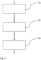
- FIG. 3 shows an example flowchart of the method.
- the method is a method for calibrating e.g. the at least one sensor 1 by use of the at least one calibration sensor 2, wherein the at least one sensor 1 and the at least one calibration sensor 2 are moving relative each other during calibration.
- the at least one sensor 1 and the at least one calibration sensor are moving since the vehicles 10 and 20 are moving.
- the vehicles 10, 20 are here moving along respective trajectories, T1, T2.
- the trajectories T1, T2 define travelling paths for the vehicles 10, 20.
- the method comprises: S1: obtaining information indicative of a proximity time period pt when the at least one sensor 1 and the at least one calibration sensor 2 are and/or will be in a predefined proximity zone PZ of each other for a time period which is sufficient for calibration.
- the predefined proximity zone PZ is here indicated by dashed lines in fig. 1 .
- the predefined proximity zone PZ may e.g. be defined by a maximum allowed distance between the at least one sensor 1 and the at least one calibration sensor 2.
- the maximum allowed distance may be 100 metres (m) from each other.
- the maximum allowed distance is highly dependent on the specific situation, type of sensor etc.
- this example is merely one example of many.
- a time period which is sufficient for calibration may be determined in e.g. minutes or seconds (s), such as 5, 10, 15 or 20 s. Of course, this time period is also highly dependent on the specific situation, type of sensor etc.
- the method further comprises:
- the sensor reading/s may cease for at least the refractory time period/s rs, rc prior to the arrival of the sensors 1, 2 in the predefined proximity zone PZ.
- Obtaining information about the refractory time period rs, rc may comprise obtaining information about a refractory time period rs for the at least one sensor 1 and a refractory time period rc for the at least one calibration sensor 2, and wherein the refractory time periods rs, rc for the at least one sensor 1 and the at least one calibration sensor 2 are considered by delaying their sensor readings such that it is ensured that the sensor readings of the at least one sensor 1 and the at least one calibration sensor 2 are spatially and temporally aligned for the calibration.
- the method may further comprise:
- the method may further comprise:
- the data in this example may be data relating to the trajectories T1, T2.
- the time table may for example be a time table for the bus 10, 20 as shown in fig. 2 .
- the method may further comprise:
- the need for calibrating the at least one sensor 1 may be identified based on an analysis of previous sensor readings of the at least one sensor 1, wherein the analysis comprises identifying a statistically significant increase in a number of outlying data points of the sensor readings.
- the at least one calibration sensor 2 may be any one of:
- the at least one calibration sensor 2 is a temperature sensor, and that the at least one sensor 1 is an air quality sensor measuring NO x levels.
- the at least one sensor 1 may be calibrated by use of the temperature information measured by the at least one calibration sensor 2 when being in the predefined proximity zone PZ while also the at least one sensor 1 is in the predefined proximity zone PZ.
- the method may further comprise:
- the at least one sensor 1 and the at least one calibration sensor 2 may form part of a system 100, wherein the at least one sensor 1 and the at least one calibration sensor 2 are adapted to be moved relative each other during calibration.
- the system 100 may be configured to perform the steps of the method according to any one of the embodiments of the first aspect of the disclosure.
- the vehicle 10 and/or the vehicle 20 may comprise at least one control unit (not shown), wherein the at least one control unit comprises hardware and/or software for performing the method as disclosed herein.
- the first vehicle 10 may be configured to perform the method as disclosed herein, e.g. by use of the aforementioned control unit.
- the first vehicle 10 and/or the second vehicle 20 preferably comprises means for wireless communication for communicating with the other vehicle and/or with an offboard control system (not shown) for vehicles.
Landscapes
- Engineering & Computer Science (AREA)
- Physics & Mathematics (AREA)
- General Physics & Mathematics (AREA)
- Chemical & Material Sciences (AREA)
- Health & Medical Sciences (AREA)
- Life Sciences & Earth Sciences (AREA)
- Remote Sensing (AREA)
- Radar, Positioning & Navigation (AREA)
- Automation & Control Theory (AREA)
- General Health & Medical Sciences (AREA)
- Biochemistry (AREA)
- Analytical Chemistry (AREA)
- Immunology (AREA)
- Pathology (AREA)
- Medicinal Chemistry (AREA)
- Food Science & Technology (AREA)
- Combustion & Propulsion (AREA)
- Human Computer Interaction (AREA)
- Transportation (AREA)
- Mechanical Engineering (AREA)
- Computer Networks & Wireless Communication (AREA)
- Testing Or Calibration Of Command Recording Devices (AREA)
Description
- The disclosure relates to a method for calibrating at least one sensor by use of at least one calibration sensor. The disclosure also relates to a system and to a first and/or second vehicle.
- The invention can be applied in heavy-duty vehicles, such as trucks, buses and construction equipment. Although the invention will be described with respect to a bus, the invention is not restricted to this particular vehicle, but may also be used in other vehicles such as passenger cars, trucks, construction equipment, such as wheel loaders, excavators etc., marine vessels and aircraft, such as drones etc.
- Vehicles may be equipped with sensors for measuring different ambient conditions. For example, it is well-known to measure the ambient temperature during driving. In addition, it is also known to measure other environmentally related properties, such as properties relating to the ambient air quality. Such sensors may for example measure the level of NOx (Nitrogen oxides), CO2 (carbon dioxide) and particle levels in the ambient air.
- The above-mentioned sensors are thus adapted to move during use, i.e. the sensors are moved with the vehicle while the vehicle is moving.
- The present invention relates to such moving sensors and to any other types of moving sensors. In particular, the present invention relates to sensors which are movable and which also would benefit from being calibrated during use.
-
WO 2017/189361 A1 relates to systems and methods for detecting miscalibration or other error in vehicular sensors and discloses to calibrate at least one sensor by use of at least one calibration sensor, wherein the at least one sensor and the at least one calibration sensor are moving relative each other during calibration. - In view of the above, an object of the invention is to provide an improved method for calibrating at least one sensor. In addition, an object of the invention is to provide an improved vehicle.
- According to the invention, also referred to as a first aspect of the disclosure, the object is achieved by a method according to
claim 1. Thus, a method for calibrating at least one sensor by use of at least one calibration sensor is provided, wherein the at least one sensor and the at least one calibration sensor are moving relative each other during calibration. The method comprises: - obtaining information indicative of a proximity time period when the at least one sensor and the at least one calibration sensor are and/or will be in a predefined proximity zone of each other for a time period which is sufficient for calibration;
- obtaining information about a refractory time period for at least one of the at least one sensor and the at least one calibration sensor, the refractory time period defining a time period between two consecutive sensor readings in which the sensor is unable to take a sensor reading;
- calibrating the at least one sensor by a sensor reading of the at least one sensor and a sensor reading of the at least one calibration sensor, which sensor readings are taken when they are in the predefined proximity zone, wherein the refractory time period for the at least one of the at least one sensor and the at least one calibration sensor is considered by delaying its sensor reading such that it is ensured that the sensor readings of the at least one sensor and the at least one calibration sensor are spatially and temporally aligned for the calibration.
- By the provision of the present invention as disclosed herein, a more accurate, reliable and robust calibration of the at least one sensor is achieved. In particular, the present invention is based on a realization that it may be important to consider the refractory time period for the calibration. The refractory time period, which also may be denoted a recovery time period, is the time period after a sensor reading when the sensor cannot initiate another sensor reading, or at least when it cannot reliably perform another sensor reading. The refractory time period may therefore be a time period when a sensor is not functioning at all or when it is not functioning with a sufficient reliability. As such, the calibration can be improved by delaying a sensor reading with respect to the refractory time period such that the at least one sensor and the at least one calibration sensor are spatially and temporally aligned for the calibration. In contrast, if not considering the refractory time period as disclosed herein, the calibration may not be properly performed. In addition, by not considering the refractory time period, an opportunity to calibrate the at least one sensor may be missed. It has namely also been realized that the time period which is sufficient for calibration may be very short for moving sensors, and therefore it may be of utmost importance that that sensors involved in the calibration are available and able to take at least one sensor reading during the short time period when the sensors are close enough to each other.
- A "predefined proximity zone" as used herein may refer to an area or space which is defined by a maximum allowed distance between the at least one sensor and the at least one calibration sensor. The area or space may e.g. be defined based on map data, coordinates or the like, and/or by evaluating a distance between the at least one sensor and the at least one calibration sensor. The distance therebetween may for example be obtained by use of GNSS (global navigation satellite system) technology.
- A "sensor reading" as used herein means a reading of a sensor when the sensor is collecting information relating to the property the sensor is measuring, wherein the sensor reading is performed during a sensor reading time period.
- Calibration of a sensor as used herein means to calibrate the sensor by e.g. adjusting its output values with respect to a reference, wherein the reference is at least based on one or more measured values of the at least one calibration sensor.
- Optionally, obtaining information about the refractory time period may comprise obtaining information about a refractory time period for the at least one sensor and a refractory time period for the at least one calibration sensor, and wherein the refractory time periods for the at least one sensor and the at least one calibration sensor are considered by delaying their sensor readings such that it is ensured that the sensor readings of the at least one sensor and the at least one calibration sensor are spatially and temporally aligned for the calibration. Thereby a further improved calibration may be achieved, taking the refractory time periods for both sensors into account. For example, the refractory time periods may be similar, but they may also be different. If the refractory time periods are different it may be required to delay the sensor readings differently such that it is ensured that the sensor readings of the at least one sensor and the at least one calibration sensor are spatially and temporally aligned for the calibration.
- Optionally, the sensor reading/s may cease for at least the refractory time period/s prior to the arrival of the sensors in the predefined proximity zone. Thereby a further improved method may be achieved since it may be assured that the sensor readings can be initiated directly when the at least one sensor and the at least one calibration sensor are in the proximity zone. A risk of missing an opportunity to calibrate the at least one sensor may thereby be mitigated.
- Optionally, the method may further comprise:
- determining the proximity time period when the at least one sensor and the at least one calibration sensor are and/or will be in the predefined proximity zone by use of information about any one or a combination of relative speed, direction of movement and geolocation of the at least one sensor and the at least one calibration sensor. Thereby a more reliable determination of when the at least one sensor and the at least one calibration sensor are and/or will be in the predefined proximity zone may be achieved. Geolocation may for example be determined by use of GNSS technology as mentioned in the above. Of course, the skilled person will recognize that geolocation may additionally or alternatively be determined in a number of other ways, for example by triangulation by use of telecommunication signals, or by any other means, such as systems using LIDAR (Light Detection And Ranging), RADAR (Radio detection And Ranging) , SONAR (SOund Navigation And Ranging), ultrasound waves etc. for identifying the geographical location of objects.
- Optionally, at least one of the at least one sensor and the at least one calibration sensor may be mounted on a vehicle or vessel. Calibration of sensors as disclosed herein has been found the be especially advantageous for sensors which are mounted on vehicles or vessels, i.e. objects which are moving in an area or space. Such sensors may advantageously be calibrated in order to function properly, especially the type of sensors disclosed herein. Still optionally, the method may further comprise:
- determining the proximity time period when the at least one sensor and the at least one calibration sensor are and/or will be in the predefined proximity zone by use of any one or a combination of:
- information about a time table associated with the vehicle or vessel;
- data indicative of a movement pattern of the vehicle or vessel.
- Thereby, by using such information and/or data, a reliable determination of the proximity time period when the at least one sensor and the at least one calibration sensor are and/or will be in the predefined proximity zone can be achieved. For example, it has been found that a time table, such as a bus time table, may be used for this purpose. Such information may also advantageously be combined with other means for determining the proximity time period, thereby further improving the determination.
- Optionally, the method may further comprise:
- identifying a need for calibrating the at least one sensor based on at least one of the following:
- a calibration schedule;
- an analysis of previous sensor readings of the at least one sensor;
- a determination that a predetermined threshold will be exceeded until a next possible opportunity to calibrate the at least one sensor, wherein the predetermined threshold is indicative of a lapsed time and/or a number of sensor readings after which the at least one sensor needs to be calibrated;
- a comparison with a known sensor data pattern indicating that calibration is needed; and
- a machine learning algorithm.
- For example, by use of machine learning, the need for calibration can be identified in an improved manner. The machine learning may for example be based on previous sensor readings and/or known sensor data from other sources, and therefrom patterns, deviations etc. may be identified.
- By identifying a need for calibrating the at least one sensor, it can be assured that the sensor needing calibration is actually calibrated when an opportunity to calibrate the sensor is given. In addition, identifying a need for calibration may also prevent any unnecessary calibration. Preventing unnecessary calibration may for example increase the sensors' service life, reduce energy consumption etc.
- Optionally, the need for calibrating the at least one sensor may be identified based on an analysis of previous sensor readings of the at least one sensor, wherein the analysis comprises identifying a statistically significant increase in a number of outlying data points of the sensor readings. The analysis may in an embodiment be included in the above-mentioned machine learning algorithm.
- Optionally, the at least one calibration sensor may be any one of:
- the same type as the at least one sensor;
- a reference sensor measuring the same property as the at least one sensor; and
- a sensor for measuring another property than the at least one sensor, which other property can be used to calibrate the at least one sensor.
- As such, the at least one calibration sensor may be any type of sensor which is suitable for the calibration. It has been realized that the at least one calibration sensor does not necessarily need to be of the same type, and may even not be configured to measure the same property. Thereby, an opportunity for calibration may appear more often, implying increased versatility.
- Optionally, the method may further comprise:
- determining when a plurality of sensors which require calibration will be in the predefined proximity zone; and
- taking the sensor readings of the plurality of sensors and/or of the at least one calibration sensor such that it is ensured that a maximum number of the plurality of sensors will be calibrated.
- Thereby, a further improved method may be achieved, allowing more sensors to be efficiently calibrated.
- Optionally, the at least one sensor and/or the at least one calibration sensor may be one of the following:
- a sensor measuring characteristics of sampled gases, liquids or particles, such as overall composition or concentration or directly measuring physical characteristics such as size, radiative or optical properties, etc.;
- a sensor measuring electromagnetic parameters;
- a temperature sensor;
- a pressure sensor;
- a humidity sensor.
- For example, the at least one sensor and/or the at least one calibration sensor may be configured to measure NOx levels, O2 levels, COx levels and/or particle levels. Yet further, the at least one sensor and/or the at least one calibration sensor may be an air quality sensor.
- Optionally, the at least one sensor may be part of an array of sensors located proximate each other, which array of sensors is calibrated according to the method disclosed herein. Still optionally, the at least one calibration sensor may be part of an array of calibration sensors located proximate each other, which array of calibration sensors is used to calibrate the at least one sensor according to the method disclosed herein.
- According to a second aspect of the disclosure, a system for calibrating at least one sensor by use of at least one calibration sensor is provided. The system comprises the at least one sensor and the at least one calibration sensor, wherein the at least one sensor and the at least one calibration sensor are adapted to be moved relative each other during calibration, and wherein the system is configured to perform the steps of the method according to any one of the embodiments of the first aspect of the invention. Advantages and effects of the second aspect of the disclosure are largely analogous to the advantages and effects of the first aspect of the disclosure. It shall also be noted that all embodiments of the first aspect of the disclosure are applicable to and combinable with all embodiments of the second aspect of the disclosure, and vice versa.
- Optionally, the system may comprise at least one control unit for performing the steps of the method as disclosed herein. The control unit is preferably an electronic control unit comprising processing circuitry for performing the method.
- As such, according to another aspect of the disclosure, a computer program is disclosed, wherein the computer program comprises program code means for causing the at least one control unit to perform the steps of any one of the embodiments of the method as disclosed herein. According to a yet further aspect of the disclosure, a computer readable medium is disclosed, wherein the computer readable medium is carrying a computer program comprising program code means to cause the at least one control unit to perform the steps of any one of the embodiments of the method as disclosed herein.
- According to the invention, also referred to a third aspect of the disclosure, the object is achieved by a first vehicle or vessel according to claim 12. Thus, a first vehicle or vessel is provided comprising at least one sensor which is configured to be calibrated by at least one calibration sensor which is remote from the first vehicle or vessel, wherein the first vehicle or vessel is configured to perform the method according to any one of the embodiments of the first aspect of the disclosure. Advantages and effects of the third aspect of the disclosure are largely analogous to the advantages and effects of the first and second aspects of the disclosure. It shall also be noted that all embodiments of the first and second aspects of the disclosure are applicable to and combinable with all embodiments of the third aspect of the disclosure, and vice versa. Optionally, the first vehicle or vessel may comprise at least one control unit as disclosed herein, and/or a computer program, computer readable medium as disclosed herein. The first vehicle or vessel may be part of the system according to any one of the embodiments of the second aspect of the disclosure.
- According to a fourth object of the disclosure, a second vehicle or vessel comprising at least one calibration sensor for calibrating at least one sensor of another vehicle is provided, wherein the second vehicle or vessel is part of the system according to any one of the embodiments of the second aspect of the disclosure. Advantages and effects of the fourth aspect of the disclosure are largely analogous to the advantages and effects of the first, second and third aspects of the disclosure. It shall also be noted that all embodiments of the first, second and third aspects of the disclosure are applicable to and combinable with all embodiments of the fourth aspect of the disclosure, and vice versa.
- Optionally, the system according to the second aspect, the first vehicle or vessel according to the third aspect and/or the second vehicle or vessel according to the fourth aspect may further comprise means for wireless communication for communicating with another vehicle or vessel and/or with an offboard control system for vehicles or vessels. Such means may for example be based on telecommunication technology, such as 3G, 4G, 5G, wireless transfer via WiFi, Bluetooth etc. For example, the first vehicle or vessel may communicate wirelessly with the second vehicle or vessel in order to coordinate the sensor readings of the at least one sensor and the at least calibration sensor as disclosed herein. The communication may be a one-way communication or a two-way communication. Additionally, or alternatively, a one-way communication or a two-way communication may be established between an offboard control system and at least one of the first vehicle or vessel and the second vehicle or vessel. The offboard control system may for example be a cloud-based system and/or a remote central for coordinating the calibration.
- The first vehicle or vessel and/or the second vehicle or vessel may be any type of vehicle, such as a truck, a bus, construction equipment, a marine vessel, a drone and a passenger car. The first and/or second vehicle or vessel may be propelled by any type of propulsion unit, such as a combustion engine, an electric motor or a combination of a combustion engine and an electric motor.
- Further advantages and advantageous features of the invention are disclosed in the following description and in the dependent claims.
- With reference to the appended drawings, below follows a more detailed description of embodiments of the invention cited as examples.
- In the drawings:
-
Fig. 1 is a schematic view of two vehicles which utilize an embodiment of the method according to the invention, -
Fig. 2 is a perspective view of a first vehicle in the form of a bus according to an example embodiment of the invention; and -
Fig. 3 is a flowchart of an example embodiment of a method according to the invention. - The drawings show diagrammatic exemplifying embodiments of the present disclosure and are thus not necessarily drawn to scale. It shall be understood that the embodiments shown and described are exemplifying and that the invention is not limited to these embodiments. It shall also be noted that some details in the drawings may be exaggerated in order to better describe and illustrate the particular embodiment. Like reference characters refer to like elements throughout the description, unless expressed otherwise.
- In
fig. 1 , afirst vehicle 10 and asecond vehicle 20 are schematically illustrated from above. The first andsecond vehicles - The
first vehicle 10 comprises at least onesensor 1 and thesecond vehicle 20 comprises at least onecalibration sensor 2. In this non-limiting example, thesensors sensor 1. According to an embodiment, the at least onecalibration sensor 2 may also need be calibrated. Therefore, the at least onecalibration sensor 2 may be calibrated in a similar manner as the at least onesensor 1. Thus, according to a yet further example embodiment, the at least onesensor 1 and the at least onecalibration sensor 2 are calibrated at the same time, by use of one another. -
Fig. 2 depicts a perspective view of abus vehicle fig. 1 may e.g. be a bus as shown infig. 2 . - With respect to
figs. 1-3 , example embodiments of a method according to the invention will be described.Fig. 3 shows an example flowchart of the method. - The method is a method for calibrating e.g. the at least one
sensor 1 by use of the at least onecalibration sensor 2, wherein the at least onesensor 1 and the at least onecalibration sensor 2 are moving relative each other during calibration. In the shown embodiments, the at least onesensor 1 and the at least one calibration sensor are moving since thevehicles vehicles vehicles - The method comprises:
S1: obtaining information indicative of a proximity time period pt when the at least onesensor 1 and the at least onecalibration sensor 2 are and/or will be in a predefined proximity zone PZ of each other for a time period which is sufficient for calibration. - The predefined proximity zone PZ is here indicated by dashed lines in
fig. 1 . As mentioned in the above, the predefined proximity zone PZ may e.g. be defined by a maximum allowed distance between the at least onesensor 1 and the at least onecalibration sensor 2. Purely by way of example, the maximum allowed distance may be 100 metres (m) from each other. Of course, the maximum allowed distance is highly dependent on the specific situation, type of sensor etc. As such, this example is merely one example of many. A time period which is sufficient for calibration may be determined in e.g. minutes or seconds (s), such as 5, 10, 15 or 20 s. Of course, this time period is also highly dependent on the specific situation, type of sensor etc. - The method further comprises:
- S2: obtaining information about a refractory time period rs, rc for at least one of the at least one
sensor 1 and the at least onecalibration sensor 2, the refractory time period defining a time period between two consecutive sensor readings in which the sensor, 1 and/or 2, is unable to take a sensor reading; and - S3: calibrating the at least one
sensor 1 by a sensor reading of the at least onesensor 1 and a sensor reading of the at least onecalibration sensor 2, which sensor readings are taken when they are in the predefined proximity zone PZ, wherein the refractory time period rs, rc for the at least one of the at least onesensor 1 and the at least onecalibration sensor 2 is considered by delaying its sensor reading such that it is ensured that the sensor readings of the at least onesensor 1 and the at least onecalibration sensor 2 are spatially and temporally aligned for the calibration. - For example, the sensor reading/s may cease for at least the refractory time period/s rs, rc prior to the arrival of the
sensors - Obtaining information about the refractory time period rs, rc may comprise obtaining information about a refractory time period rs for the at least one
sensor 1 and a refractory time period rc for the at least onecalibration sensor 2, and wherein the refractory time periods rs, rc for the at least onesensor 1 and the at least onecalibration sensor 2 are considered by delaying their sensor readings such that it is ensured that the sensor readings of the at least onesensor 1 and the at least onecalibration sensor 2 are spatially and temporally aligned for the calibration. - The method may further comprise:
- determining the proximity time period pt when the at least one
sensor 1 and the at least onecalibration sensor 2 are and/or will be in the predefined proximity zone PZ by use of information about any one or a combination of relative speed, direction of movement and geolocation of the at least onesensor 1 and the at least onecalibration sensor 2. For example, by using information about the trajectories T1, T2 it may be possible to determine the proximity time period pt when the at least onesensor 1 and the at least onecalibration sensor 2 are and/or will be in the predefined proximity zone PZ. - Additionally, or alternatively, the method may further comprise:
- determining the proximity time period pt when the at least one
sensor 1 and the at least onecalibration sensor 2 are and/or will be in the predefined proximity zone PZ by use of any one or a combination of: - information about a time table associated with the
vehicles - data indicative of a movement pattern of the
vehicle - Accordingly, the data in this example may be data relating to the trajectories T1, T2. In addition, the time table may for example be a time table for the
bus fig. 2 . - The method may further comprise:
- identifying a need for calibrating the at least one
sensor 1 based on at least one of the following:- a calibration schedule;
- an analysis of previous sensor readings of the at least one
sensor 1; - a determination that a predetermined threshold will be exceeded until a next possible opportunity to calibrate the at least one
sensor 1, wherein the predetermined threshold is indicative of a lapsed time and/or a number of sensor readings after which the at least onesensor 1 needs to be calibrated; - a comparison with a known sensor data pattern indicating that calibration is needed; and
- a machine learning algorithm.
- Additionally, or alternatively, the need for calibrating the at least one
sensor 1 may be identified based on an analysis of previous sensor readings of the at least onesensor 1, wherein the analysis comprises identifying a statistically significant increase in a number of outlying data points of the sensor readings. - As mentioned in the above, the example in
fig. 1 relates to air quality sensors. However, the at least onecalibration sensor 2 may be any one of: - the same type as the at least one
sensor 1; - a reference sensor measuring the same property as the at least one
sensor 1; and - a sensor for measuring another property than the at least one sensor, which other property can be used to calibrate the at least one
sensor 1. - An example of another property may be that the at least one
calibration sensor 2 is a temperature sensor, and that the at least onesensor 1 is an air quality sensor measuring NOx levels. As such, the at least onesensor 1 may be calibrated by use of the temperature information measured by the at least onecalibration sensor 2 when being in the predefined proximity zone PZ while also the at least onesensor 1 is in the predefined proximity zone PZ. - The method may further comprise:
- determining when a plurality of sensors which require calibration will be in the predefined proximity zone PZ; and
- taking the sensor readings of the plurality of sensors and/or of the at least one
calibration sensor 2 such that it is ensured that a maximum number of the plurality of sensors will be calibrated. For example, more than two vehicles with sensors may be in the predefined proximity zone PZ. - According to the second aspect of the disclosure, the at least one
sensor 1 and the at least onecalibration sensor 2 may form part of asystem 100, wherein the at least onesensor 1 and the at least onecalibration sensor 2 are adapted to be moved relative each other during calibration. Accordingly, thesystem 100 may be configured to perform the steps of the method according to any one of the embodiments of the first aspect of the disclosure. For example, thevehicle 10 and/or thevehicle 20 may comprise at least one control unit (not shown), wherein the at least one control unit comprises hardware and/or software for performing the method as disclosed herein. - According to a yet further aspect, the
first vehicle 10 may be configured to perform the method as disclosed herein, e.g. by use of the aforementioned control unit. - The
first vehicle 10 and/or thesecond vehicle 20 preferably comprises means for wireless communication for communicating with the other vehicle and/or with an offboard control system (not shown) for vehicles. - It is to be understood that the present invention is not limited to the embodiments described above and illustrated in the drawings; rather, the skilled person will recognize that many changes and modifications may be made within the scope of the appended claims.
Claims (13)
- A method for calibrating at least one sensor (1) by use of at least one calibration sensor (2), wherein the at least one sensor (1) and the at least one calibration sensor (2) are moving relative each other during calibration, the method comprising:- obtaining (S1) information indicative of a proximity time period (pt) when the at least one sensor (1) and the at least one calibration sensor (2) are and/or will be in a predefined proximity zone (PZ) of each other for a time period which is sufficient for calibration;- obtaining (2) information about a refractory time period (rs, rc) for at least one of the at least one sensor and the at least one calibration sensor, the refractory time period defining a time period between two consecutive sensor readings in which the sensor is unable to take a sensor reading;- calibrating (S3) the at least one sensor by a sensor reading of the at least one sensor and a sensor reading of the at least one calibration sensor, which sensor readings are taken when they are in the predefined proximity zone (PZ), wherein the refractory time period (rs, rc) for the at least one of the at least one sensor and the at least one calibration sensor is considered by delaying its sensor reading such that it is ensured that the sensor readings of the at least one sensor (1) and the at least one calibration sensor (2) are spatially and temporally aligned for the calibration.
- The method according to claim 1, wherein obtaining information about the refractory time period comprises obtaining information about a refractory time period (rs) for the at least one sensor (1) and a refractory time period (rc) for the at least one calibration sensor (2), and wherein the refractory time periods (rs, rc) for the at least one sensor (1) and the at least one calibration sensor (2) are considered by delaying their sensor readings such that it is ensured that the sensor readings of the at least one sensor (1) and the at least one calibration sensor (2) are spatially and temporally aligned for the calibration.
- The method according to any one of the preceding claims, wherein the sensor reading/s cease for at least the refractory time period/s (rs, rc) prior to the arrival of the sensors in the predefined proximity zone (PZ).
- The method according to any one of the preceding claims, further comprising:- determining the proximity time period (pt) when the at least one sensor (1) and the at least one calibration sensor (2) are and/or will be in the predefined proximity zone (PZ) by use of information about any one or a combination of relative speed, direction of movement and geolocation of the at least one sensor (1) and the at least one calibration sensor (2).
- The method according to any one of the preceding claims, wherein at least one of the at least one sensor (1) and the at least one calibration sensor (2) is mounted on a vehicle (10, 20) or vessel.
- The method according to claim 5, further comprising:- determining the proximity time period (pt) when the at least one sensor (1) and the at least one calibration sensor (2) are and/or will be in the predefined proximity zone (PZ) by use of any one or a combination of:- information about a time table associated with the vehicle (10, 20) or vessel;- data indicative of a movement pattern of the vehicle (10, 20) or vessel.
- The method according to any one of the preceding claims, further comprising:- identifying a need for calibrating the at least one sensor (1) based on at least one of the following:- a calibration schedule;- an analysis of previous sensor readings of the at least one sensor (1);- a determination that a predetermined threshold will be exceeded until a next possible opportunity to calibrate the at least one sensor (1), wherein the predetermined threshold is indicative of a lapsed time and/or a number of sensor readings after which the at least one sensor (1) needs to be calibrated;- a comparison with a known sensor data pattern indicating that calibration is needed; and- a machine learning algorithm.
- The method according to claim 7, wherein the need for calibrating is identified based on an analysis of previous sensor readings of the at least one sensor (1), wherein the analysis comprises identifying a statistically significant increase in a number of outlying data points of the sensor readings.
- The method according to any one of the preceding claims, wherein the at least one calibration sensor (2) is any one of:- the same type as the at least one sensor;- a reference sensor measuring the same property as the at least one sensor; and- a sensor for measuring another property than the at least one sensor, which other property can be used to calibrate the at least one sensor.
- The method according to any one of the preceding claims, further comprising:- determining when a plurality of sensors which require calibration will be in the predefined proximity zone (PZ); and- taking the sensor readings of the plurality of sensors and/or of the at least one calibration sensor such that it is ensured that a maximum number of the plurality of sensors will be calibrated.
- The method according to any one of the preceding claims, wherein the at least one sensor (1) and/or the at least one calibration sensor (2) is one of the following:- a sensor measuring characteristics of sampled gases, liquids or particles, such as overall composition or concentration or directly measuring physical characteristics such as size, radiative or optical properties, etc.;- a sensor measuring electromagnetic parameters;- a temperature sensor;- a pressure sensor;- a humidity sensor.
- A first vehicle (10) or vessel comprising at least one sensor (1) which is configured to be calibrated by at least one calibration sensor (2) which is remote from the first vehicle or vessel, wherein the first vehicle (10) or vessel is configured to perform the method according to any one of claims 1-11.
- The first vehicle (10) or vessel according to claim 12, further comprising means for wireless communication for communicating with another vehicle or vessel and/or with an offboard control system for vehicles or vessels.
Priority Applications (3)
| Application Number | Priority Date | Filing Date | Title |
|---|---|---|---|
| EP21156156.8A EP4043836B1 (en) | 2021-02-10 | 2021-02-10 | A method for calibrating at least one sensor by use of at least one calibration sensor |
| CN202111532729.XA CN114910109A (en) | 2021-02-10 | 2021-12-15 | Method for calibrating at least one sensor by using at least one calibration sensor |
| US17/647,538 US11946918B2 (en) | 2021-02-10 | 2022-01-10 | Method for calibrating at least one sensor by use of at least one calibration sensor |
Applications Claiming Priority (1)
| Application Number | Priority Date | Filing Date | Title |
|---|---|---|---|
| EP21156156.8A EP4043836B1 (en) | 2021-02-10 | 2021-02-10 | A method for calibrating at least one sensor by use of at least one calibration sensor |
Publications (2)
| Publication Number | Publication Date |
|---|---|
| EP4043836A1 EP4043836A1 (en) | 2022-08-17 |
| EP4043836B1 true EP4043836B1 (en) | 2023-09-20 |
Family
ID=74586820
Family Applications (1)
| Application Number | Title | Priority Date | Filing Date |
|---|---|---|---|
| EP21156156.8A Active EP4043836B1 (en) | 2021-02-10 | 2021-02-10 | A method for calibrating at least one sensor by use of at least one calibration sensor |
Country Status (3)
| Country | Link |
|---|---|
| US (1) | US11946918B2 (en) |
| EP (1) | EP4043836B1 (en) |
| CN (1) | CN114910109A (en) |
Family Cites Families (13)
| Publication number | Priority date | Publication date | Assignee | Title |
|---|---|---|---|---|
| US20090172035A1 (en) * | 2007-12-31 | 2009-07-02 | Pieter Lessing | System and method for capturing and storing casino information in a relational database system |
| US8325061B2 (en) * | 2010-01-07 | 2012-12-04 | Emilcott Associates, Inc. | System and method for mobile environmental measurements and displays |
| WO2017189361A1 (en) * | 2016-04-29 | 2017-11-02 | Pcms Holdings, Inc. | System and method for calibration of vehicle sensors assisted by inter-vehicle communication |
| WO2017193100A1 (en) * | 2016-05-06 | 2017-11-09 | Qelzal Corporation | Event-based aircraft sense and avoid system |
| CN106707873B (en) * | 2017-01-16 | 2019-02-26 | 上海兆芯集成电路有限公司 | Sense the method for data synchronization and its device between hub and application processor |
| US10553044B2 (en) * | 2018-01-31 | 2020-02-04 | Mentor Graphics Development (Deutschland) Gmbh | Self-diagnosis of faults with a secondary system in an autonomous driving system |
| US11262339B2 (en) * | 2018-10-09 | 2022-03-01 | Airlib Inc. | Remote sensor calibration system |
| US10969470B2 (en) * | 2019-02-15 | 2021-04-06 | May Mobility, Inc. | Systems and methods for intelligently calibrating infrastructure devices using onboard sensors of an autonomous agent |
| US11703882B2 (en) * | 2019-05-21 | 2023-07-18 | U.S. Government as represented by the Secretary of the Air Force | Bio-hybrid odor-guided autonomous palm-sized air vehicle |
| US20210063165A1 (en) * | 2019-08-30 | 2021-03-04 | Mentor Graphics Deutschland (Germany) GmbH | Adaptive map-matching-based vehicle localization |
| US11798191B2 (en) * | 2020-03-27 | 2023-10-24 | Intel Corporation | Sensor calibration and sensor calibration detection |
| US20230243678A1 (en) * | 2020-06-24 | 2023-08-03 | Volvo Truck Corporation | Local measurements using multiple moving sensors |
| US20230266079A1 (en) * | 2020-08-05 | 2023-08-24 | Active Energy Systems | Heat exchange system for freezing, transferring, storing, and utilizing phase change material and application of that system to a thermal energy storage system |
-
2021
- 2021-02-10 EP EP21156156.8A patent/EP4043836B1/en active Active
- 2021-12-15 CN CN202111532729.XA patent/CN114910109A/en active Pending
-
2022
- 2022-01-10 US US17/647,538 patent/US11946918B2/en active Active
Also Published As
| Publication number | Publication date |
|---|---|
| US20220252563A1 (en) | 2022-08-11 |
| CN114910109A (en) | 2022-08-16 |
| EP4043836A1 (en) | 2022-08-17 |
| US11946918B2 (en) | 2024-04-02 |
Similar Documents
| Publication | Publication Date | Title |
|---|---|---|
| KR102635379B1 (en) | Method and apparatus for vehicle maneuver planning and messaging | |
| CN105799617B (en) | Method for the misalignment for determining object sensor | |
| CN101256713B (en) | Driving assist system and vehicle-mounted apparatus | |
| CN101625797B (en) | Early warning method when automobile closes at high speed and early warning device | |
| CN110972066B (en) | Train and safety positioning system thereof | |
| CN110103852B (en) | System and method for collision detection in autonomous vehicles | |
| CN107850444B (en) | Travel control method and travel controlling system | |
| JP4548604B2 (en) | Inter-vehicle communication system | |
| CN103096247A (en) | Method And System For Controlling Relative Position Between Vehicles Using A Mobile Base Station | |
| CN107590768A (en) | Method for being handled the position for means of transport and/or the sensing data in direction | |
| KR102487155B1 (en) | System and method for vulnerable road user collision prevention | |
| US11435439B2 (en) | Multibounce target mitigation | |
| CN105931495B (en) | A kind of spacing anti-collision prewarning apparatus and method based on car networking | |
| CN107091647B (en) | Navigation method for horizontally carrying unmanned vehicle by port container | |
| US11435434B2 (en) | Multibounce target additional data | |
| US20210312726A1 (en) | Asset and Vehicle Coupling | |
| EP4078557A1 (en) | Intersection trajectory determination and messaging | |
| EP4043836B1 (en) | A method for calibrating at least one sensor by use of at least one calibration sensor | |
| CN201465309U (en) | Device prewarning when vehicle approaches at high speed | |
| CN205810137U (en) | A kind of spacing anti-collision prewarning apparatus based on car networking | |
| JP2004171269A (en) | Collision-of-movable-body prediction device and collision-of-movable-body prediction method | |
| WO2023154134A1 (en) | Vehicle-originated wireless safety alert | |
| US11292307B2 (en) | Suspension fault diagnostics and prognostics using pitch and roll model | |
| JP2022103546A (en) | Vehicle control device, vehicle control method, and program | |
| KR102637830B1 (en) | Methods, electronic control devices and systems for position determination |
Legal Events
| Date | Code | Title | Description |
|---|---|---|---|
| PUAI | Public reference made under article 153(3) epc to a published international application that has entered the european phase |
Free format text: ORIGINAL CODE: 0009012 |
|
| STAA | Information on the status of an ep patent application or granted ep patent |
Free format text: STATUS: THE APPLICATION HAS BEEN PUBLISHED |
|
| AK | Designated contracting states |
Kind code of ref document: A1 Designated state(s): AL AT BE BG CH CY CZ DE DK EE ES FI FR GB GR HR HU IE IS IT LI LT LU LV MC MK MT NL NO PL PT RO RS SE SI SK SM TR |
|
| STAA | Information on the status of an ep patent application or granted ep patent |
Free format text: STATUS: REQUEST FOR EXAMINATION WAS MADE |
|
| 17P | Request for examination filed |
Effective date: 20230126 |
|
| RBV | Designated contracting states (corrected) |
Designated state(s): AL AT BE BG CH CY CZ DE DK EE ES FI FR GB GR HR HU IE IS IT LI LT LU LV MC MK MT NL NO PL PT RO RS SE SI SK SM TR |
|
| GRAP | Despatch of communication of intention to grant a patent |
Free format text: ORIGINAL CODE: EPIDOSNIGR1 |
|
| STAA | Information on the status of an ep patent application or granted ep patent |
Free format text: STATUS: GRANT OF PATENT IS INTENDED |
|
| INTG | Intention to grant announced |
Effective date: 20230515 |
|
| GRAS | Grant fee paid |
Free format text: ORIGINAL CODE: EPIDOSNIGR3 |
|
| GRAA | (expected) grant |
Free format text: ORIGINAL CODE: 0009210 |
|
| STAA | Information on the status of an ep patent application or granted ep patent |
Free format text: STATUS: THE PATENT HAS BEEN GRANTED |
|
| AK | Designated contracting states |
Kind code of ref document: B1 Designated state(s): AL AT BE BG CH CY CZ DE DK EE ES FI FR GB GR HR HU IE IS IT LI LT LU LV MC MK MT NL NO PL PT RO RS SE SI SK SM TR |
|
| REG | Reference to a national code |
Ref country code: GB Ref legal event code: FG4D |
|
| REG | Reference to a national code |
Ref country code: CH Ref legal event code: EP |
|
| REG | Reference to a national code |
Ref country code: IE Ref legal event code: FG4D |
|
| REG | Reference to a national code |
Ref country code: DE Ref legal event code: R096 Ref document number: 602021005191 Country of ref document: DE |
|
| REG | Reference to a national code |
Ref country code: LT Ref legal event code: MG9D |
|
| PG25 | Lapsed in a contracting state [announced via postgrant information from national office to epo] |
Ref country code: GR Free format text: LAPSE BECAUSE OF FAILURE TO SUBMIT A TRANSLATION OF THE DESCRIPTION OR TO PAY THE FEE WITHIN THE PRESCRIBED TIME-LIMIT Effective date: 20231221 |
|
| REG | Reference to a national code |
Ref country code: NL Ref legal event code: MP Effective date: 20230920 |
|
| PG25 | Lapsed in a contracting state [announced via postgrant information from national office to epo] |
Ref country code: SE Free format text: LAPSE BECAUSE OF FAILURE TO SUBMIT A TRANSLATION OF THE DESCRIPTION OR TO PAY THE FEE WITHIN THE PRESCRIBED TIME-LIMIT Effective date: 20230920 Ref country code: RS Free format text: LAPSE BECAUSE OF FAILURE TO SUBMIT A TRANSLATION OF THE DESCRIPTION OR TO PAY THE FEE WITHIN THE PRESCRIBED TIME-LIMIT Effective date: 20230920 Ref country code: NO Free format text: LAPSE BECAUSE OF FAILURE TO SUBMIT A TRANSLATION OF THE DESCRIPTION OR TO PAY THE FEE WITHIN THE PRESCRIBED TIME-LIMIT Effective date: 20231220 Ref country code: LV Free format text: LAPSE BECAUSE OF FAILURE TO SUBMIT A TRANSLATION OF THE DESCRIPTION OR TO PAY THE FEE WITHIN THE PRESCRIBED TIME-LIMIT Effective date: 20230920 Ref country code: LT Free format text: LAPSE BECAUSE OF FAILURE TO SUBMIT A TRANSLATION OF THE DESCRIPTION OR TO PAY THE FEE WITHIN THE PRESCRIBED TIME-LIMIT Effective date: 20230920 Ref country code: HR Free format text: LAPSE BECAUSE OF FAILURE TO SUBMIT A TRANSLATION OF THE DESCRIPTION OR TO PAY THE FEE WITHIN THE PRESCRIBED TIME-LIMIT Effective date: 20230920 Ref country code: GR Free format text: LAPSE BECAUSE OF FAILURE TO SUBMIT A TRANSLATION OF THE DESCRIPTION OR TO PAY THE FEE WITHIN THE PRESCRIBED TIME-LIMIT Effective date: 20231221 Ref country code: FI Free format text: LAPSE BECAUSE OF FAILURE TO SUBMIT A TRANSLATION OF THE DESCRIPTION OR TO PAY THE FEE WITHIN THE PRESCRIBED TIME-LIMIT Effective date: 20230920 |
|
| REG | Reference to a national code |
Ref country code: AT Ref legal event code: MK05 Ref document number: 1613713 Country of ref document: AT Kind code of ref document: T Effective date: 20230920 |
|
| PG25 | Lapsed in a contracting state [announced via postgrant information from national office to epo] |
Ref country code: NL Free format text: LAPSE BECAUSE OF FAILURE TO SUBMIT A TRANSLATION OF THE DESCRIPTION OR TO PAY THE FEE WITHIN THE PRESCRIBED TIME-LIMIT Effective date: 20230920 |
|
| PG25 | Lapsed in a contracting state [announced via postgrant information from national office to epo] |
Ref country code: IS Free format text: LAPSE BECAUSE OF FAILURE TO SUBMIT A TRANSLATION OF THE DESCRIPTION OR TO PAY THE FEE WITHIN THE PRESCRIBED TIME-LIMIT Effective date: 20240120 |
|
| PG25 | Lapsed in a contracting state [announced via postgrant information from national office to epo] |
Ref country code: AT Free format text: LAPSE BECAUSE OF FAILURE TO SUBMIT A TRANSLATION OF THE DESCRIPTION OR TO PAY THE FEE WITHIN THE PRESCRIBED TIME-LIMIT Effective date: 20230920 |
|
| PG25 | Lapsed in a contracting state [announced via postgrant information from national office to epo] |
Ref country code: ES Free format text: LAPSE BECAUSE OF FAILURE TO SUBMIT A TRANSLATION OF THE DESCRIPTION OR TO PAY THE FEE WITHIN THE PRESCRIBED TIME-LIMIT Effective date: 20230920 |
|
| PG25 | Lapsed in a contracting state [announced via postgrant information from national office to epo] |
Ref country code: SM Free format text: LAPSE BECAUSE OF FAILURE TO SUBMIT A TRANSLATION OF THE DESCRIPTION OR TO PAY THE FEE WITHIN THE PRESCRIBED TIME-LIMIT Effective date: 20230920 Ref country code: RO Free format text: LAPSE BECAUSE OF FAILURE TO SUBMIT A TRANSLATION OF THE DESCRIPTION OR TO PAY THE FEE WITHIN THE PRESCRIBED TIME-LIMIT Effective date: 20230920 Ref country code: IS Free format text: LAPSE BECAUSE OF FAILURE TO SUBMIT A TRANSLATION OF THE DESCRIPTION OR TO PAY THE FEE WITHIN THE PRESCRIBED TIME-LIMIT Effective date: 20240120 Ref country code: ES Free format text: LAPSE BECAUSE OF FAILURE TO SUBMIT A TRANSLATION OF THE DESCRIPTION OR TO PAY THE FEE WITHIN THE PRESCRIBED TIME-LIMIT Effective date: 20230920 Ref country code: EE Free format text: LAPSE BECAUSE OF FAILURE TO SUBMIT A TRANSLATION OF THE DESCRIPTION OR TO PAY THE FEE WITHIN THE PRESCRIBED TIME-LIMIT Effective date: 20230920 Ref country code: CZ Free format text: LAPSE BECAUSE OF FAILURE TO SUBMIT A TRANSLATION OF THE DESCRIPTION OR TO PAY THE FEE WITHIN THE PRESCRIBED TIME-LIMIT Effective date: 20230920 Ref country code: AT Free format text: LAPSE BECAUSE OF FAILURE TO SUBMIT A TRANSLATION OF THE DESCRIPTION OR TO PAY THE FEE WITHIN THE PRESCRIBED TIME-LIMIT Effective date: 20230920 Ref country code: PT Free format text: LAPSE BECAUSE OF FAILURE TO SUBMIT A TRANSLATION OF THE DESCRIPTION OR TO PAY THE FEE WITHIN THE PRESCRIBED TIME-LIMIT Effective date: 20240122 Ref country code: SK Free format text: LAPSE BECAUSE OF FAILURE TO SUBMIT A TRANSLATION OF THE DESCRIPTION OR TO PAY THE FEE WITHIN THE PRESCRIBED TIME-LIMIT Effective date: 20230920 |
|
| PGFP | Annual fee paid to national office [announced via postgrant information from national office to epo] |
Ref country code: DE Payment date: 20240228 Year of fee payment: 4 |