EP4016572A1 - Release element - Google Patents
Release element Download PDFInfo
- Publication number
- EP4016572A1 EP4016572A1 EP22155462.9A EP22155462A EP4016572A1 EP 4016572 A1 EP4016572 A1 EP 4016572A1 EP 22155462 A EP22155462 A EP 22155462A EP 4016572 A1 EP4016572 A1 EP 4016572A1
- Authority
- EP
- European Patent Office
- Prior art keywords
- emergency button
- door
- security system
- control device
- lighting means
- Prior art date
- Legal status (The legal status is an assumption and is not a legal conclusion. Google has not performed a legal analysis and makes no representation as to the accuracy of the status listed.)
- Granted
Links
- 230000007246 mechanism Effects 0.000 claims description 79
- 230000006870 function Effects 0.000 claims description 75
- 230000004913 activation Effects 0.000 claims description 41
- 238000012806 monitoring device Methods 0.000 claims description 24
- 230000009471 action Effects 0.000 claims description 19
- 230000000007 visual effect Effects 0.000 claims description 15
- 239000003086 colorant Substances 0.000 claims description 11
- 238000012545 processing Methods 0.000 description 207
- 238000004891 communication Methods 0.000 description 37
- 238000001994 activation Methods 0.000 description 36
- 230000015654 memory Effects 0.000 description 32
- 230000009849 deactivation Effects 0.000 description 23
- 230000000875 corresponding effect Effects 0.000 description 11
- 230000007480 spreading Effects 0.000 description 11
- 230000005540 biological transmission Effects 0.000 description 8
- 238000010586 diagram Methods 0.000 description 7
- 239000000463 material Substances 0.000 description 7
- 238000013461 design Methods 0.000 description 6
- 230000000977 initiatory effect Effects 0.000 description 6
- 238000010295 mobile communication Methods 0.000 description 6
- 230000003287 optical effect Effects 0.000 description 6
- 238000003825 pressing Methods 0.000 description 6
- 230000001934 delay Effects 0.000 description 5
- 230000003111 delayed effect Effects 0.000 description 5
- 230000003247 decreasing effect Effects 0.000 description 4
- 230000002950 deficient Effects 0.000 description 4
- 238000009434 installation Methods 0.000 description 4
- 230000006978 adaptation Effects 0.000 description 3
- 239000002390 adhesive tape Substances 0.000 description 3
- 230000004397 blinking Effects 0.000 description 3
- 230000008859 change Effects 0.000 description 3
- 230000007423 decrease Effects 0.000 description 3
- 238000001514 detection method Methods 0.000 description 3
- 230000001419 dependent effect Effects 0.000 description 2
- 238000011161 development Methods 0.000 description 2
- 230000018109 developmental process Effects 0.000 description 2
- 230000000694 effects Effects 0.000 description 2
- 230000001771 impaired effect Effects 0.000 description 2
- 238000003780 insertion Methods 0.000 description 2
- 230000037431 insertion Effects 0.000 description 2
- 230000003340 mental effect Effects 0.000 description 2
- 238000000034 method Methods 0.000 description 2
- 238000012544 monitoring process Methods 0.000 description 2
- 230000008569 process Effects 0.000 description 2
- 230000000452 restraining effect Effects 0.000 description 2
- 238000012546 transfer Methods 0.000 description 2
- 230000001960 triggered effect Effects 0.000 description 2
- 206010012289 Dementia Diseases 0.000 description 1
- 235000014676 Phragmites communis Nutrition 0.000 description 1
- 241000826860 Trapezium Species 0.000 description 1
- 230000003213 activating effect Effects 0.000 description 1
- 230000001276 controlling effect Effects 0.000 description 1
- 230000002596 correlated effect Effects 0.000 description 1
- 230000001066 destructive effect Effects 0.000 description 1
- 239000011888 foil Substances 0.000 description 1
- 239000011521 glass Substances 0.000 description 1
- 231100001261 hazardous Toxicity 0.000 description 1
- 239000004922 lacquer Substances 0.000 description 1
- 230000006996 mental state Effects 0.000 description 1
- 239000013307 optical fiber Substances 0.000 description 1
- 230000008447 perception Effects 0.000 description 1
- 230000000717 retained effect Effects 0.000 description 1
- 238000012552 review Methods 0.000 description 1
Images


Classifications
-
- H—ELECTRICITY
- H01—ELECTRIC ELEMENTS
- H01H—ELECTRIC SWITCHES; RELAYS; SELECTORS; EMERGENCY PROTECTIVE DEVICES
- H01H3/00—Mechanisms for operating contacts
- H01H3/02—Operating parts, i.e. for operating driving mechanism by a mechanical force external to the switch
- H01H3/022—Emergency operating parts, e.g. for stop-switch in dangerous conditions
-
- E—FIXED CONSTRUCTIONS
- E05—LOCKS; KEYS; WINDOW OR DOOR FITTINGS; SAFES
- E05B—LOCKS; ACCESSORIES THEREFOR; HANDCUFFS
- E05B17/00—Accessories in connection with locks
- E05B17/10—Illuminating devices on or for locks or keys; Transparent or translucent lock parts; Indicator lights
-
- E—FIXED CONSTRUCTIONS
- E05—LOCKS; KEYS; WINDOW OR DOOR FITTINGS; SAFES
- E05B—LOCKS; ACCESSORIES THEREFOR; HANDCUFFS
- E05B65/00—Locks or fastenings for special use
- E05B65/10—Locks or fastenings for special use for panic or emergency doors
- E05B65/108—Electronically controlled emergency exits
-
- H—ELECTRICITY
- H01—ELECTRIC ELEMENTS
- H01H—ELECTRIC SWITCHES; RELAYS; SELECTORS; EMERGENCY PROTECTIVE DEVICES
- H01H13/00—Switches having rectilinearly-movable operating part or parts adapted for pushing or pulling in one direction only, e.g. push-button switch
- H01H13/02—Details
- H01H13/023—Light-emitting indicators
-
- H—ELECTRICITY
- H01—ELECTRIC ELEMENTS
- H01H—ELECTRIC SWITCHES; RELAYS; SELECTORS; EMERGENCY PROTECTIVE DEVICES
- H01H3/00—Mechanisms for operating contacts
- H01H3/02—Operating parts, i.e. for operating driving mechanism by a mechanical force external to the switch
- H01H3/022—Emergency operating parts, e.g. for stop-switch in dangerous conditions
- H01H2003/0233—Emergency operating parts, e.g. for stop-switch in dangerous conditions for alarm triggering, e.g. fire alarm, emergency off switches operated by breaking a glass
-
- H—ELECTRICITY
- H01—ELECTRIC ELEMENTS
- H01H—ELECTRIC SWITCHES; RELAYS; SELECTORS; EMERGENCY PROTECTIVE DEVICES
- H01H13/00—Switches having rectilinearly-movable operating part or parts adapted for pushing or pulling in one direction only, e.g. push-button switch
- H01H13/02—Details
- H01H13/023—Light-emitting indicators
- H01H2013/026—Light-emitting indicators with two or more independent lighting elements located inside the push button switch that illuminate separate zones of push buttons
-
- H—ELECTRICITY
- H01—ELECTRIC ELEMENTS
- H01H—ELECTRIC SWITCHES; RELAYS; SELECTORS; EMERGENCY PROTECTIVE DEVICES
- H01H2219/00—Legends
- H01H2219/036—Light emitting elements
- H01H2219/039—Selective or different modes of illumination
-
- H—ELECTRICITY
- H01—ELECTRIC ELEMENTS
- H01H—ELECTRIC SWITCHES; RELAYS; SELECTORS; EMERGENCY PROTECTIVE DEVICES
- H01H2219/00—Legends
- H01H2219/054—Optical elements
- H01H2219/062—Light conductor
Definitions
- the invention relates to a triggering element, in particular an emergency button, for unlocking at least one door lock, in particular for securing escape routes, the triggering element comprising lighting means for displaying a locked and/or unlocked state of a door lock.
- the invention also relates to a safety system with a triggering element according to the invention, in particular an emergency button.
- the emergency button includes at least light sources with which a locked state and an unlocked state of a door lock can be visualized.
- the lamps light up green when unlocked and red when locked.
- the user receives information from the light source as to whether the door is unlocked and the user can escape through the door. By flashing the lamps, it can be signaled that the door is only open for a certain period of time.
- the disadvantage here is that only these states are displayed to the user by the lighting means. Other statuses of the security system are not indicated by the lamps.
- a triggering element in particular an emergency button
- a safety system which at least reduces the disadvantage mentioned above.
- a triggering element, in particular an emergency button which indicates at least one further state of the safety system in a simple design.
- a triggering element in particular an emergency button, according to independent claim 1.
- Advantageous developments of the triggering element are specified in the dependent claims, the description and in the figures.
- a safety system with a triggering element according to the invention is also protected.
- Advantageous developments of the security system are specified in the dependent claims, the description and in the figures.
- Features and details that are described in connection with the triggering element according to the invention also apply in connection with the safety system according to the invention and vice versa.
- the features mentioned in the description and in the claims can each be essential to the invention individually or in combination.
- the lighting means can each be controlled in at least two groups. Because the light sources can be controlled in at least two groups, each group can light in a different way emit. It is thus conceivable that not all groups of lighting devices emit light at the same time, emit light of the same color and/or flash at the same frequency. By controlling each group individually, the number of options for displaying at least one additional status of the security system to the user through the lighting means can be increased enormous.
- the total number of light sources of the triggering element is denoted by n.
- a group can contain 1 to n-1 lamps in such a way that the number of lamps in the groups add up to n.
- at least one of the light sources can be controlled individually.
- a group of light sources can therefore also include only one light source.
- At least several of the light sources can preferably be controlled individually.
- Each light source can particularly preferably be controlled individually.
- the triggering element includes n groups of light sources, each group including only one of the light sources.
- the lamps which are already used to indicate the locked and/or unlocked state, can be controlled in groups, in particular individually.
- the lighting means can also be used to display the at least one further state of the security system.
- the triggering element according to the invention can therefore be produced without using additional components, in particular additional lighting means.
- a triggering element that indicates at least one further state of the safety system in a particularly simple manner is thus made available.
- At least the locked or the unlocked state of the door lock is preferably displayed by all the lamps. This can be z. B. be the locked state of the door lock. In particular, the unlocked state and the locked state can be displayed by all light sources.
- the triggering element can comprise an actuating element.
- the actuating element can be actuated by a user in such a way that an actuating signal for actuating the door lock can be generated by actuating the actuating element.
- the actuation element can move, in particular, from an initial position into an actuation position.
- a restoring means can be used to move the actuating element back into the starting position after actuation.
- the restoring means particularly preferably moves the actuating element back into the starting position without manual action.
- the actuating element can return to the starting position immediately after the actuation.
- the restoring means can be designed as a spring.
- the actuator may include a front surface facing the user.
- the triggering element is preferably an emergency button.
- the actuating element corresponds to the actuating element of the emergency button.
- the triggering element can be designed as a panic bar assembly.
- the actuating element is designed as a panic bar.
- the triggering element can be designed as a fitting assembly.
- the actuator z. B. designed as a door handle.
- the light sources can be in the form of multiple color light sources.
- the lighting means can in particular be in the form of multi-color LEDs.
- each illuminant has a number of individual LEDs.
- the light sources are particularly preferably designed as RGB LEDs.
- the different colors can be generated in part by the simultaneous light emission of the individual LEDs of the multi-color LED. In this case, different colors can be generated by different light components of the individual LEDs.
- the lighting means can be controlled in such a way that light can be emitted by the lighting means in at least two, preferably in at least three, particularly preferably in at least four different colors.
- the light sources can emit red, green, yellow and blue light. Due to the different colors, different statuses of the security system can be displayed particularly well.
- the triggering element in particular the emergency button, preferably comprises at least one triggering element processing unit, in particular an emergency button processing unit.
- the lighting means can particularly preferably be controlled by the triggering element processing unit.
- the triggering element processing unit in particular the emergency button processing unit, can be designed digitally and/or electronically.
- the trigger element processing unit may include a processor.
- the trigger element processing unit may include at least one non-volatile memory.
- the trigger element processing unit may be a microprocessor or microcontroller.
- the lighting means can be connected to a bus, in particular a ring bus.
- the triggering element processing unit can control the lighting means by means of the bus, in particular the ring bus.
- the lamps can be arranged in a circle.
- the lighting means can be arranged in a circle around the actuating element.
- the lighting means can be controlled in such a way that at the same time at least one lighting means lights up light in one color and another lighting means lights up in a different color emitted. So e.g. B. a bulb emit yellow light and another bulb red or green light at the same time. This can result in light patterns that are significantly perceptible to the user.
- the lighting means can be controlled in such a way that at least one lighting means periodically alternately emits light of different colors.
- a light source can e.g. B. flashing red and yellow alternately. This can also result in significantly perceptible patterns for the user. It is also possible for at least one lamp to continuously emit light in a time interval while at least one other lamp is flashing.
- the impression of a "circular color window" can arise in that neighboring lamps in each case assume one color one after the other, while other lamps in particular otherwise light up in a different color or not at all.
- the lighting means are preferably controlled in order to indicate the presence of a fire alarm signal.
- the further state of the security system which is indicated by the lighting means that can be controlled in groups, can therefore be the state of a security system in which a fire alarm signal is present.
- a fire detector can transmit a fire alarm signal to the security system.
- the lighting means can be controlled when the actuating element has been actuated, in particular in order to unlock the door lock.
- the further state of the security system which is indicated by the lighting means that can be controlled in groups, can therefore be the state of a security system in which an actuating element has been actuated.
- the presence of a fire alarm signal and the presence of a completed actuation of the actuating element are preferably displayed in different ways by the lighting means.
- the lamps can be controlled if a central emergency button of the security system has been pressed to unlock the door lock.
- the actuation of the central emergency button is preferably displayed in a different way than the presence of the fire alarm signal and/or the presence of a successful actuation of the actuating element by the lighting means.
- the triggering element can be brought into a deactivated state. If the triggering element is actuated in the deactivated state, the triggering element does not cause unlocking of the door lock.
- the deactivated state can be caused by the lamps are displayed.
- the further state of the security system which is indicated by the lighting means that can be controlled in groups, can therefore be the deactivated state. It is conceivable that a parameterization program can be used to set the lighting means not to display the deactivated state. This is particularly advantageous in a psychiatric ward.
- the illuminants may serve to indicate a time progression duration.
- the time progression duration is a countdown.
- the countdown can be determined using a timer, in particular using a timer of the triggering element.
- the time progress duration can be e.g. B. be a predetermined period of time, after which a re-locking of the door lock is automatically initiated. This is particularly possible if there is no dangerous situation.
- the further state of the security system which is indicated by the lighting means that can be controlled in groups, can thus be the time span from unlocking to automatic relocking.
- the time period a distinction can be made between a predetermined short time period and a predetermined long time period.
- the actuation of the illuminants for the short period of time can differ from the actuation of the illuminants for the long period of time.
- the time progress period can also be a predetermined period of time in which the automatic relocking has failed and an alarm is therefore issued in this predetermined period of time.
- the further state of the security system which is displayed by the lighting means that can be controlled in groups, can be the period of time of the failed re-locking, in which an alarm is output.
- the alarm can be a pre-alarm and/or a main alarm.
- the lighting means can be controlled differently in the case of a pre-alarm than in the case of a main alarm.
- the door lock is transferred from the locked to the unlocked state with a time delay.
- the lighting means can be controlled in such a way that the progression of the time delay is indicated by the lighting means.
- the further state of the security system which is indicated by the lighting means that can be controlled in groups, can therefore be the state of a security system with time-delayed unlocking.
- the length of the time delay is called the delay time.
- the time advance duration can correspond to the delay duration.
- both a first delay period that must elapse before the door lock is converted to the unlocked state and/or a second delay period that must elapse before the door lock is converted to the unlocked state can be visually displayed by the lighting means .
- the actuation of a locking mechanism of the door lock for unlocking can be delayed by a first delay period.
- a delay action by an operator, in particular the operation of a delay element, within the first delay time period can cause the delay in activation of the locking mechanism to be lengthened by a second delay time period.
- the delaying action can be carried out in particular at a central escape route control.
- the delay element can be part of the central escape route control of the security system.
- an increasing or decreasing number of lamps can light up in a first color.
- the remaining light sources can, in particular, light up in a second color or not.
- the glow may be continuous light emission or blinking.
- the lamps are controlled in such a way that at the end of the time progression period, the last illuminant still emitting the first color stops emitting light or switches to the second color.
- the lamps are controlled in such a way that at the end of the time progression the last lamp not yet emitting the first color begins to emit light in the first color or switched to light emission of the first color.
- each illuminant is activated exactly once in order to start light emission in the first color or to start light emission in the first color until to end at the end of the time progression duration.
- each illuminant can in particular be activated exactly once in order to end light emission in the first color by the end of the time progress duration.
- each illuminant can in particular be activated exactly once in order to start light emission in the first color.
- the duration of the progression of time thus corresponds to a one-time passage through the illuminants.
- the duration of the progression of time corresponds exactly to one revolution of the lamps.
- the user receives feedback as to how far the time progression has progressed. It is conceivable that each light source is activated at a different point in time for this purpose. As a result, a time segment of the duration of the progression of time is represented by each individual light source.
- the one-time activation during the time progress period to start or end the emission in the first color does not preclude that each lamp can be activated multiple times in order to emit light of the first color, be it that the lamp emits light of the first color flashing or that the illuminants are activated in rapid succession for the short-term interruption of light emission.
- the impression of a downcounter arises at least once, preferably several times, during the time progression period, in that the lamps are briefly switched off one after the other and then switched on again.
- the visual representation of the time progress duration may be repeatedly interrupted by a pattern symbolizing a passage of time.
- the duration of the progression of time can be represented by lighting up lamps in the first color one after the other.
- one lamp in each case lights up in the first color, while the other lamps light up in a second color or not at all.
- each illuminant only lights up in the first color during a single time segment of the duration of the progression of time.
- the duration of the progression of time thus corresponds to a one-time passage through the illuminants.
- the duration of the progression of time corresponds exactly to one revolution of the lamps. The user receives feedback as to how far the time progression has progressed.
- the lighting means are preferably activated during the progression of time, in particular the predetermined time period, the predetermined time period, the first and/or second delay time period, in particular at regular time intervals.
- the time progress duration is displayed in a linear manner.
- the predetermined time period, the predetermined time period, the first and/or second delay time period can each be represented differently. So u. a. the first color can be chosen differently for different time advance durations.
- the time advance duration in particular the predetermined time span, the predetermined time duration, the first and/or second delay time duration, can preferably be set by an operator.
- the operator can set the time advance duration through the parameterization program.
- the activation of the lighting means is preferably adapted to the set time progression duration.
- the time intervals at which the lamps are activated are adapted to the set time advance duration.
- the adaptation is particularly preferably carried out in such a way that at the end of the time progression period, the last illuminant not yet emitting the first light begins to emit light in the first color or the last illuminant still emitting the first light stops emitting light in the first color.
- the adaptation can take place in such a way that during the time progression period each luminous means is driven exactly once in order to start light emission in the first color or to end it for the time progression period.
- the adaptation can take place in such a way that the lighting means are activated at regular time intervals in particular.
- the lighting means to be activated in order to indicate an error in the security system.
- the further state of the safety system which is indicated by the lighting means that can be controlled in groups, can therefore be the state of a safety system that is faulty.
- the error may be that a component of the security system is inoperable, defective, failed, intentionally turned off, or removed. At least one of these errors for at least one component of the security system can be indicated by the light source.
- the component of the safety system may be a control device, a door lock or a part of the control device, the door lock and/or the triggering element, e.g. the trigger element processing unit.
- the error can be that the security system has a signal that a component connected to the security system, e.g. B. an alarm system is not operational, defective, failed, deliberately switched off or removed. At least one of these errors for at least one component connected to the security system can be indicated by the lighting means. A number of the faults mentioned can preferably be displayed by the lighting means.
- Different types of activation of the lighting means are preferably provided for different faults.
- different errors are displayed in different ways by the lighting means.
- the mistake or mistakes can in different ways to indicate a dangerous situation, e.g. B. the presence of a fire alarm signal or the actuation of the trigger element.
- the triggering element in particular the emergency button, comprises at least three triggering element processing units, in particular emergency button processing units.
- a first trigger element processing unit can be embodied as a first emergency button processing unit.
- a second triggering element processing unit can be designed as a second emergency button processing unit.
- a third triggering element processing unit can be designed as a third emergency button processing unit.
- the first, second and third trigger element processing units may each comprise a processor.
- the first and second trigger element processing units may each include at least one non-volatile memory.
- the third trigger element processing unit may include non-volatile memory and/or have access to non-volatile memory.
- each of the first, second, and third trigger processing units may be a microprocessor or microcontroller.
- the first and the second trigger element processing units can be used to detect the actuation signal. At least two actuating signals are preferably generated by actuating the actuating element. For this z. B. at least two circuits open.
- the first and the second trigger element processing unit can each independently detect an actuation signal. In this case, the first triggering element processing unit detects a first actuation signal and the second triggering element processing unit detects a second actuation signal.
- the first and the second trigger element processing unit can thereupon in each case independently trigger the activation of a door locking mechanism for unlocking.
- the first and the second trigger element processing unit each independently detect an actuation signal. Because the first and the second trigger element processing units detect the actuation signal independently of one another, there is redundancy with regard to the unlocking of the door after the trigger element has been actuated.
- the triggering element includes an acoustic alarm.
- the acoustic alarm can, for. B. serve to issue an alarm if the trigger element was actuated and / or after receiving a fire alarm signal.
- the activation of the acoustic alarm device and/or the lamps is redundant. It is conceivable that the third trigger element processing unit controls the acoustic alarm and/or the lighting means.
- the brightness of the lighting means can be adjustable to the ambient brightness.
- the brightness of the lamps can decrease when the ambient brightness decreases. This can prevent the user from being bothered by excessive brightness.
- a brightness sensor can be provided to adapt to the ambient brightness in order to detect the ambient brightness. Depending on the detection of the ambient brightness, the brightness of the lamps can be adjusted.
- predetermined periods of time and brightnesses correlated therewith for the lighting means can be stored in a non-volatile memory of the security system. The brightness for different times of the day and night can be specified by the specified periods of time.
- the triggering element in particular the emergency button, preferably comprises a light guide.
- the light guide can serve to guide the light emitted by the lighting means in the direction of the surface of the triggering element that is visible to the user.
- the light emitted by illuminants can be made visible to the user in a particularly pleasing way by means of the light guide.
- the light guide is preferably designed in such a way that the different activation of the at least two groups of light sources is visible to the user.
- the light guide can have light guide areas that are assigned to each group of light sources. If lighting means can be controlled individually, a light guide area can be assigned to each lighting means that can be controlled individually. Each light source can particularly preferably be controlled individually and each light source is assigned a light guide area.
- the surface of the light guide that is visible to the user can be perceived at least divided into luminous areas.
- Each light guide area can include a luminous area. Emission of light from a lighting means preferably results essentially only in the lighting of the associated lighting area.
- the lighting means are located in the center below the lighting areas, in particular in the direction of the surface of the triggering element.
- the surface of the light guide that is visible to the user can be designed, for example, as a circular ring.
- the luminous areas can, in particular, each correspond to a sector of the circular ring.
- gaps are provided between the light guide areas.
- the cutouts in the light guide are provided so that the light sources, which can be controlled differently, cannot be routed from one light guide area to the other.
- the recesses are located between the groups of light sources, in particular the individual light sources.
- the light guide areas are located in the direction of the surface of the triggering element above the lighting means.
- the light guide areas each include a spreading section.
- the expanding section can be used to spread the light emitted by the associated illuminant. As a result, the emitted light can be distributed over the associated lighting area.
- the spreading section can in a projection z. B. in the shape of a trapezoid, in particular in the shape of an isosceles trapezium.
- the expanding section can expand in a longitudinal section. As a result, the lighting area can be widened.
- the area of the spread-apart end of the spread-apart section corresponds in particular to the luminous area in terms of size and/or shape. As a result, the emitted light can be distributed particularly well over the associated lighting area.
- the expanding section is preferably arranged in the direction of the surface of the triggering element above the lighting means. As a result, the light emitted by the lamps reaches the light guide particularly well.
- the forwarding section is thus arranged between the expanding section and the associated illuminant.
- the forwarding section serves to forward the light emitted by the illuminant to the spreading section.
- the forwarding section can spread at least less than the spreading section.
- the forwarding section can thus have edges that are parallel to one another in the direction of the light guide.
- the forwarding section may be provided when the light guide is a plate, e.g. B. the mounting plate or a circuit board, protrudes. Since the spreading section begins near the lighting area due to the forwarding section, the light guide can have a small space requirement at the height of the plate to be projected through. Thus, the stability of the plate can be guaranteed.
- the light guide is preferably designed in one piece.
- the light guide can also be made of the same material.
- the light guide is particularly preferably designed as a monolith.
- the light guide is made in particular from translucent material.
- the light guide area can have a connection section.
- the connecting section can be used to connect the light guide areas to one another.
- the connection areas of the light guide areas merge into one another in one piece, particularly preferably monolithically.
- the light from the lighting means can preferably be guided through the expanding section to the connecting section.
- the connecting section can join the expanding section in the direction of the light guide.
- the connection portion may include the luminous area.
- the connection areas together can comprise the surface facing the user.
- the connecting section can have a depth of 2 mm to 6 mm, preferably 3 mm to 5 mm, particularly preferably 3.5 mm to 4.5 mm.
- the recesses are designed to be particularly deep, so that the light guide areas are separated to a particularly large extent. Thus essentially only the lighting area is illuminated by the associated lighting means.
- the depth of the connecting section nevertheless enables a mechanically stable, one-piece light guide.
- the surface of the light guide that is visible to the user can be flat.
- the surface of the light guide that is visible to the user can be concave.
- the light guide surrounds the actuating element.
- the light guide and the actuating element can be arranged concentrically with one another.
- the light guide may be partially located within the actuator and/or the front face of the actuator may cover the light guide from the user's perspective.
- the front surface of the actuating element is preferably transparent or translucent where the light guide is covered.
- the contact surface can hold the actuating element in a form-fitting manner, in particular against an actuating direction. It may be that the restoring means presses the actuating element against the contact surface.
- the triggering element can have a cover.
- the light guide can be fixed within the trigger element.
- the light guide can be attached to a mounting plate.
- the mounting plate can be used to attach the release element to a flush-mounted socket and/or a surface-mounted housing.
- the light guide can have a flange with which the light guide is fixed within the trigger element.
- the flange can be attached to the mounting plate. Due to the fact that the light guide itself is fastened within the triggering element, the light guide can reliably hold the actuating element against the direction of actuation with the contact surface. In particular, the hold is retained even when the cover of the triggering element is removed.
- the fastening means which are used to fasten the flange to the mounting plate, can particularly preferably include at least one further component, e.g. B. connect a circuit board to the mounting plate.
- An illuminating area is preferably formed in the center of the front surface of the operating member.
- the illuminating area is translucent and can be illuminated by a light source located behind it.
- a crest of the front surface can be formed as the light-transmitting illuminating area. Due to the conical design, the illuminating area of the actuating element can be clearly visible from all sides. This applies in particular if the light-transmitting illuminating area protrudes beyond the cover. The overhang occurs in the opposite direction to the direction of actuation.
- the illuminating area is illuminated by a light source. It is conceivable that a front surface of the actuating element, in particular the illuminating area, protrudes at most 10 mm, preferably at most 7 mm, particularly preferably at most 5 mm above the light guide. As a result, the light guide is also clearly visible to users standing at an angle in front of the triggering element.
- the front surface of the operating member may be partially concave.
- the front face can be conical around the illuminating area.
- an area of the front surface that covers the light guide can be concave.
- the lighting means can preferably be controlled in such a way that lighting means lying opposite one another emit the same optical signal.
- Opposite lighting means are understood to mean, in particular, lighting means which can be connected to one another by a straight line passing through a center of symmetry of the lighting means arrangement.
- the same optical signal is understood to mean, in particular, the emission of the same color and/or the same frequency when the lamp is flashing.
- illuminants arranged in a mirror-inverted manner can emit the same optical signal.
- the mirror plane is preferably placed through the center of symmetry.
- the emission of the same optical signal for lamps located opposite one another and/or mirror-symmetrical lamps is conceivable for at least one further state of the security system, in particular for states other than the predetermined time period, the predetermined time period and/or the first and/or the second delay period.
- it can be the presence of a fire alarm signal and/or a previously performed actuation of the actuating element and/or sabotage of the triggering element.
- the triggering element can have an at least partially transparent covering means.
- the covering means can cover the actuating element, so that the actuating element can be actuated via the covering means.
- the actuating element can preferably only be actuated via the covering means.
- the covering means can be arranged in particular in a non-removable manner in the triggering element.
- the covering means can be permanently connected to the actuating element.
- the covering means can additionally or alternatively be mounted in a non-removable manner in the triggering element or in a housing in which the triggering element is arranged, or on a fastening plate to which the triggering element is fastened.
- the covering means eliminates the need to adapt the actuating element to the haptic needs of the user.
- the actuator z. B. be adapted by the conical shape of the best perception possibility of the light emitted over the Illuminier Scheme.
- the actuating element does not have to protrude far beyond the cover and/or the light guide. This can take over the covering means.
- an actuation surface of the covering means is formed at a distance from the front surface of the actuation element that faces the actuation surface.
- an actuating surface spaced apart from the front surface e.g. B. to a larger operating path, i.e. to a larger distance between the starting position and the operating position of the operating element and / or contribute to an operation with a flat hand.
- the actuating surface of the covering means can protrude beyond the cover of the triggering element in such a way that the distance between the starting position and the actuating position in the direction of actuation corresponds at most to the distance between the actuating surface, in particular an elevation of the actuating surface, and the cover.
- the triggering element can be actuated with the palm of your hand.
- the covering means is shaped and transparent in such a way that the light guide is visible through the covering means.
- the light guide can thus be visible through the covering means spaced apart from the front surface, in particular when viewed from the front or at an angle.
- the light guide preferably closes essentially flat with the cover.
- the light guide can deviate from a planar termination with the cover by a maximum of ⁇ 3 mm, preferably a maximum of ⁇ 2 mm, particularly preferably a maximum of ⁇ 1 mm.
- a safety system with a triggering element according to the invention.
- the triggering element according to the invention in particular the emergency button according to the invention, can be designed as described in the description, the drawings and/or the claims.
- the security system is used in particular to secure escape routes.
- the safety system thus serves to release the escape route. i.e. actuation of the actuating element leads to unlocking without authentication of the user. Unlocking can be immediate or delayed.
- a user can be anyone who uses the security system. For example, a user can B. be a guest who wants to escape through the door secured by the security system.
- the security system may include door locking.
- the door latch may include a latch mechanism.
- the locking mechanism can e.g. B. be formed electromechanically or purely electromagnetically.
- the locking mechanism includes z. B. at least one coil. Activation of the locking mechanism for locking or unlocking can be implemented in particular by switching an electrical power supply on or off.
- the electrical power supply can be used to supply the coil with electrical current.
- An electromechanical locking mechanism has a mechanical connection to the door when locked. In the unlocked state, the mechanical connection can be canceled or canceled.
- the electromechanical locking mechanism z. B. have a locking element, ie a bolt or a door latch, which is in the unlocked state of the door lock in a retracted position. In the withdrawn Position is the locking element disengaged from the door. In the locked state, the latch member is engaged with the door.
- the locking mechanism is constructed in the manner of a door opener. i.e. the locking mechanism includes a latch member. In the locked state of the door lock, a door latch of the door is engaged with the locking mechanism. In the unlocked state, the latch element releases the door latch in such a way that the door latch, in particular by pressure on the door, can disengage from the locking mechanism.
- Switching off the electrical power supply preferably leads to an unlocked state of the door lock.
- the locking mechanism for unlocking the door lock is thus activated by switching off the electrical power supply.
- Switching on the electrical power supply preferably leads to a locked state of the door lock.
- the control of the locking mechanism for locking is implemented by switching on the electrical power supply.
- the safety system can be designed without the locking mechanism.
- the safety system only controls the locking mechanism.
- the security system turns on or off the electrical power supply to the locking mechanism, or causes the electrical power supply to be turned on or off.
- An “actuation for locking or unlocking” also occurs when the security system receives feedback on the status of the locking mechanism. "Triggering to lock or unlock” also occurs when, as detected by the feedback, the locking mechanism does not conform to the target state and therefore an alarm is issued and/or another attempt is made to reach the target state .
- the security system may include a door lock controller. If a door locking control is provided, the door locking control preferably controls the locking mechanism. To do this, the door lock controller can switch the electrical power supply for the locking mechanism on and off.
- the door lock may include the door lock controller.
- the security system may include the door latch controller but not the latch mechanism.
- the door locking control is designed as a door locking adapter.
- the door lock adapter is used to use the security system according to the invention with locking mechanisms that have already been installed.
- the door locking controller and the triggering element are preferably connected to a first bus system.
- a connection to a bus system is understood below to mean a direct connection, so that a component connected to the bus system is to be regarded as a bus system participant with its own bus address.
- the door locking controller and the triggering element are connected to one another via the first bus system.
- the triggering element can directly control the locking mechanism for unlocking. Alternatively and particularly preferably, the triggering element triggers activation of the locking mechanism for unlocking. Initiating a control is in particular sending a message, e.g. B. on the first bus system, understood that contains information and / or a command that causes the direct or indirect recipient of the message to make the control. The sender of the message initiates the activation. Initiating a triggering is thus understood to mean an indirect triggering. So e.g. B. send the triggering element a message via the first bus system to the door lock controller, whereupon the door lock controller controls the locking mechanism for unlocking. The triggering element can in particular cause the unlocking of the locking mechanism with a time delay.
- the security system can be designed in such a way that, in addition to the unlocked and/or locked state of the door lock, if there is a further state of the security system, the lamps can be controlled to display the further state, with the further state being selectable by an operator of the security system. It is thus conceivable that not only the manner in which the lighting means are activated, but also the state in which the lighting means are activated can be set by the operator. In particular, a color to be emitted by the lighting means and/or a color pattern can be reserved for the setting. For example, the emission of green and red light by all light sources for the locked and the unlocked state can be permanently specified. However, the operator can choose in which state of the safety system at least some of the lamps emit blue light.
- the operator can set that in the deactivated state of the triggering element, the lighting means of the relevant triggering element emit blue light.
- the setting can be made via the mobile communication device, in particular a cell phone.
- the mobile communication device can communicate with a radio module of the triggering element.
- the setting can, for example, via a switch, z. B. via a DIP switch.
- the door locks can B. each be provided for a stationary and a moving leaf of a door. The door should be able to be unlocked by actuating the release element. For this purpose, the door locks are actuated after actuation of the trigger element.
- the operator can decide whether the lamps only have an unlocked state, e.g. by emitting a green light, when the full escape route width is available, i. H. the passive and active leaf are unlocked, or whether the lamps indicate an unlocked status when there is already an escape route through a door leaf.
- This setting option represents an inventive idea in itself, regardless of whether the lighting means can be controlled in at least two groups or not.
- the security system may be that several door locking controls are provided for a door, it being possible in the security system to set whether the door locking control immediately causes a locked state when the door locking control receives a signal to lock, independently of a within the signal received by the security system that at least part of the door is in an open position and the lamps indicate an unlocked state until all door locking controls for the door have established a locked state, or whether the door locking controls only initiate the locked state if there is at least one signal within the security system a fully closed position of the door and the lamps only indicate an unlocked condition if no door lock controls have established a locked condition.
- the security system may include a controller.
- the control device is connected to the first bus system.
- the control device comprises at least digital processing electronics.
- the digital processing electronics can include at least one digital processing unit.
- the digital processing unit may include a processor and non-volatile memory.
- the digital processing electronics can comprise a first processing unit, a second processing unit and a third processing unit.
- the first, second and third processing units may each comprise a processor.
- the first, the second and the third processing unit can each be in the form of a microprocessor or microcontroller.
- the first, second and third processing units may each include non-volatile memory.
- the third processing unit in particular can have access to a non-volatile memory.
- the control device can be integrated in the trigger element or the door lock control.
- the trigger element or the door lock control can comprise the control device.
- the control device can be connected to the triggering element and the door locking controller via a bus system, in particular via a first bus system.
- the third triggering element processing unit serves at the same time as the third processing unit of the control device.
- the first triggering element processing unit can serve as the first processing unit of the control device and the second triggering element processing unit can serve as the second processing unit of the control device.
- the change in the status of the door lock is preferably only displayed by the lighting means after the door lock controller has sent a corresponding signal to the triggering element and/or the control device via the bus system.
- control device i. to iv. causes the trigger element to control the lamps.
- the control device preferably initiates in several, particularly preferably in all, of the above cases i. to iv. the trigger element to control the lamps.
- parameters are stored in particular in the control device, in which way and way in which case the light sources are to be controlled.
- the processing electronics in particular the third processing unit, can communicate with the electronics unit, in particular the third triggering element processing unit, via the first bus system and thus initiate the actuation.
- the control device can be connected or can be connected to a second bus system.
- a control center of the security system in particular a security device, a central escape route control and/or a multi-door display device, can be connected to the second bus system.
- the control device is used to route or forward messages to the control center or to receive or forward messages from the control center.
- the control device can be designed in particular to initiate non-safety-related locking or unlocking.
- control device can control the door locking mechanism for unlocking after receiving a positive authentication signal or cause such a control.
- control device can be connected or can be connected to an access control system.
- the control device can, for. B. control the door locking mechanism for unlocking at a predetermined time or cause such a control.
- the unlocking at a predetermined time can be provided if z. B. the door should be unlocked in a time window per day.
- the control device can activate the door locking mechanism for automatic relocking after the predetermined period of time has elapsed, or can initiate such an activation.
- the control device activates the locking mechanism for automatic relocking immediately after receiving a signal about a closed state of the door or initiates such an activation.
- the closed state of the door can be detected by at least one door state monitoring device.
- the safety system prevents activation of a further door locking mechanism after activation of a first door locking mechanism until a condition is present such that a lock is formed.
- a first door at an entrance to a Room and a second door can be arranged at an exit of the same room.
- the security system in particular the control device, z. B. cause an unlocking of the door lock of the first door in the presence of a positive authentication signal for a door lock of the first door. Even if a positive authentication signal for the door lock of the second door is present to the security system, in particular the control device, the security system, in particular the control device, can prevent the unlocking of the door lock of the second door until a condition is present. If the condition is present, the safety system, in particular the control device, causes the door lock of the second door to be unlocked.
- the lighting means can indicate that the actuation of the further door locking mechanism is prevented. In this way, the user receives in particular the feedback that the lack of a positive authentication signal does not prevent the unlocking of the second door.
- Which functions the security system can perform can depend on a communication module. Depending on the communication module used, more or fewer functions can be executable by the security system.
- the communication module is arranged in particular in a receptacle of the security system. Functions of the security system can be activated in particular by the arrangement in the receptacle, so that the security system can carry out the functions.
- the components can be the door lock, the door lock controller, the triggering element, the control device or parts of the triggering element or the control device, such as inputs and/or outputs of a processing unit and/or a triggering element processing unit.
- the inputs and/or outputs can be the connection to the first bus system, to a second bus system, to a bus input via which authentication of an authorized user is communicated, to the input of a key switch and/or the like.
- the security system has a number of triggering elements and/or a number of door locking controls.
- the multiple triggering elements and/or the multiple door locking controls can be connected to the first bus system.
- the lighting means can display the status of the multiple triggering elements and/or multiple door locking controls, in particular at the same time. It is conceivable that at least one lamp is permanently assigned to one of the triggering elements and/or one of the door locking controls. The display can take place in particular when the security system is started up.
- the lighting means can represent which functions the control device can perform.
- the communication module used can be displayed by the lighting means. Which functions can be executed can be displayed in particular when the safety system is put into operation.
- each lamp can be assigned several states and/or functions to be displayed.
- the number of states and/or functions displayed can therefore exceed the number of lamps.
- the states of the triggering elements and the door locking controls can be displayed first, then the states of the inputs and outputs and then the executable functions by displaying the communication module used.
- a different sequence can of course also be selected.
- the activation of the lighting means which is used to display the status of the components or the executable functions of the control device one after the other, can therefore include at least one further activation of the lighting means, at least in addition to a first activation.
- the further actuation of the lighting means can take place after a predetermined time lapse or alternatively after a conscious action.
- the lighting means can be controlled in such a way that the lighting means indicate the ability to carry out at least one function of the control device and/or the status of a component, in particular the door locking control or the door locking controls and/or the triggering element or the Show trigger elements, in particular lamps are permanently assigned to a door lock control and / or a trigger element.
- the electronic memory can be a non-volatile memory of the triggering element processing unit and/or a act processing unit.
- the manner of activation can include a flashing frequency, a color selection and/or a color pattern. It can be adjustable whether a predetermined period of time is to be displayed without blinking.
- the setting can be made via the mobile communication device, in particular a cell phone.
- the mobile communication device can communicate with the radio module.
- a user can be anyone who uses the security system 1 .
- a user can B. be a guest who wants to escape through the door secured by the security system 1.
- An operator is used to operate the security system 1.
- the operator can z. B. to authenticate against the security system.
- the operator can B. Be a member of a security guard.
- the operator can particularly preferably set the safety system 1 .
- actuation of the emergency button means "actuation of the actuating element of the emergency button”.
- connection to a bus system is understood below to mean a direct connection, so that a component connected to the bus system is to be regarded as a bus system participant with its own bus address.
- Initiating an activation is understood in particular as meaning the sending of a message via a first and/or second bus system, which message contains information and/or a command which causes the direct or indirect recipient of the message to carry out the activation.
- the sender of the message initiates the activation.
- Initiating a triggering is thus understood to mean an indirect triggering.
- the message can correspond to a bus telegram.
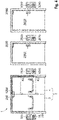
- a first exemplary embodiment of a security system 1 according to the invention for a door 2 is shown.
- the door 2 is not part of the safety system 1 according to the invention.
- the safety system 1 according to the invention comprises a door lock 200 and an emergency button 10.
- the emergency button 10 comprises a control device 100.
- a key switch 500 is assigned to the emergency button 10.
- the security system 1 can include the key switch 500 .
- the security system 1, in particular the emergency button 10 have a key switch input via which a connection to the key switch 500 can be established.
- the emergency button 10 and the door lock 200 are connected to one another via a first bus system 400 .
- the key switch 500 is electrically connected or connectable to the emergency button 10 via a connection 402 .
- the connection 402 is shown as a dashed arrow to show that signals about a position of a key inserted into the key switch 500 are fed to an electronic unit 24 of the emergency switch 10 .
- the key switch 500 can also be connected to the first bus system 400 (not shown). This alternative applies to all exemplary embodiments.
- the emergency button 10 is designed to send a message to the door lock 200 as a result of an actuation of the emergency button 10 via the first bus system 400 and thereby to cause the door lock to be unlocked.
- the message as a result of pressing the emergency button 10 can be delayed.
- the security system 1 in particular the emergency button 10, can also be connectable to a fire alarm (not shown). If a fire alarm signal is present, the security system 1 also causes the door lock 200 to be unlocked.
- the control device 100 does not carry out safety-related functions: The control device 100 can thus cause the door lock 200 to be unlocked for authorized persons.
- the control device 100 can be connected to an access control system (not shown).
- the access control system can be connected or can be connected to the first bus system 400 .
- the control device 100 receives from the access control system, in particular via the bus system 400, a positive authentication signal about the authentication that has taken place. Thereafter, the control device 100 causes an unlocking of the door lock 200.
- the access control system can, for. B. a reader, a key switch, a keyboard for entering a code or a lock cylinder of a mechanical lock, in particular a self-locking panic lock, include or be designed in such a way.
- control device 100 can automatically trigger an unlocking of the door lock 200 at a specified time or after a specified period of time, e.g. B. if the door should be unlocked in a time window per day.
- the control device 100 can automatically initiate a re-locking after a predetermined period of time has elapsed.
- the control device 100 can also receive an access signal from the access control system and/or measure the length of the positive authentication signal.
- the control device 100 can adapt the length of the predetermined period of time by means of the access signal or based on the length of the authentication signal. For example, a person can B. hold an ID card in front of the reader for a long time or turn the key for a long time. This signals that the predetermined period of time should correspond to a long period of time previously stored in control device 100 . If the person holds the ID card briefly in front of the reader or if the user turns the key briefly, a signal is given that the predetermined period of time should correspond to a short period of time previously stored in the control device 100 .
- a first door status monitor 204 and a second door status monitor 206 detect whether the door 2 is open or closed.
- the control device 100 receives at least indirectly a signal from the door status monitoring devices 204, 206. If the door lock 200 has been unlocked due to a positive authentication signal, the control device 100 can immediately and automatically cause the door lock 200 to be locked again as soon as the control device 100 with the aid of the door status monitoring devices 204, 206 the information is available that the door is first opened and now closed again.
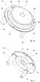
- the emergency button 10 includes an acoustic alarm device 23 and light source 41 (see also figure 13 ).
- the lamps 41 are used to display the locked or unlocked state of the door lock 200 and thus serve as a display device.
- the lamps 41 are used for the visual representation of a time-delayed unlocking of the door lock 200 as a result of an actuation of the emergency button 10 and thus serve as a display device.
- the lamps 41 are used for the visual representation of an alarm condition after receipt of the fire alarm signal or as a result of pressing the emergency button 10 and thus serve as a display.
- the lamps 41 are used for visual display when a previously described re-locking fails.
- the control device 100 controls the acoustic alarm generator 23 in order to emit an acoustic alarm when there is a dangerous situation, ie when a Fire alarm signal received or emergency button 10 pressed.
- the control device 100 controls the acoustic alarm generator 23 in order to emit an acoustic alarm if re-locking fails.
- the control device 100 controls the lamps 41 to display the locking or unlocking status of the door lock 200, to visually display a time-delayed unlocking and/or to emit a visual alarm when a fire alarm signal is received or the emergency button 10 has been actuated, or when relocking fails.
- the control device 100 can monitor the opening of the door with the aid of the door state monitoring devices 204, 206. If desired, the control device 100 can have an acoustic alarm emitted if the door 2 was opened while the door lock 200 was in the unlocked state, at least if there is no positive authentication signal. This way it can be monitored when someone opens the door, even if the door is unlocked.
- the emergency button 10 can include at least one additional output.
- the control device 100 can use the output to control other components that can be connected to the security system 1 according to the invention, e.g. B. a room light.
- the parameters for executing the named functions of the control device 100 are stored in the control device 100 .
- the predetermined time (s), the predetermined period of time (s), parameters for the audible alarms, e.g. B. in which volume with which frequency an acoustic alarm is to be output, and parameters for the different activations of the light sources 41 for visual representation of the different, above-mentioned states of the security system 1 are stored in the control device 100 .
- the parameters for the light sources can include flashing frequencies, colors to be emitted, color intensities and/or lighting patterns.
- the control device 100 can communicate with a mobile communication device via a radio module 64 .
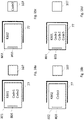
- the parameters can be set using a monitoring device 301 via a second bus system 401 (see Fig. Figures 9 and 10 ).
- a parameterization program is provided for parameterization, which runs on a communication device, e.g. B. a personal computer, a mobile phone and / or a tablet, executable. The operator can set the parameters using the parameterization program.
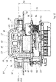
- FIG 2 the structure of the door lock 200 and the emergency button 10 is shown in more detail.
- the emergency button 10 has a first emergency button processing unit 20 , a second emergency button processing unit 21 and a third emergency button processing unit 22 .
- the first, the second and the third emergency button processing unit 20, 21, 22 are each designed as microprocessors or microcontrollers.
- the first and the second emergency button processing units 20, 21 comprise a non-volatile memory.
- the third emergency button processing unit 22 includes a non-volatile memory and/or has access to a non-volatile memory.
- the first, second and third emergency button processing unit 20, 21, 22 are collectively referred to as the electronic unit 24 of the emergency button 10.
- Electronics unit 24 also serves as control device 100.
- First emergency button processing unit 20 serves as first processing unit 103 of control device 100.
- Second emergency button processing unit 21 serves as second processing unit 104 of control device 100.
- Third emergency button processing unit 22 serves as third processing unit 105 of control device 100.
- the first and the second emergency button processing unit 20, 21 are used to carry out the safety-related functions of the emergency button.
- the third emergency button processing unit 22 or processing unit 105 is used to carry out the non-safety-related functions.
- One of the safety-relevant functions is the initiation of unlocking in the event of danger.
- the non-safety-related functions include the other functions listed above.
- an actuating element 11 When the emergency button 10 is actuated, an actuating element 11 is moved from a starting position 11.I to an actuating position 11.II, whereby a switch 63 is actuated (see also figures 12 , 13 ). As a result, a first and a second actuation signal are generated. This opens a first and a second circuit (not shown). A first circuit opening signal is detected by the first emergency button processing unit 20 . A signal about the opening of the second circuit is detected by the second emergency button processing unit 21 .
- the actuation signal is understood to be the signal generated by the user by actuating the actuating element in order to unlock the door lock and release the escape route.
- the first emergency button processing unit 20 and the second emergency button processing unit 21 each cause an unlocking of the door lock 200 via the first bus system 400 after detecting the actuation signal.
- the second Emergency button processing unit 21 thus acts redundantly to the first emergency button processing unit 20.
- the door lock 200 includes a door lock controller 201.
- the door lock controller 201 includes a first processing means 202 and a second processing means 203.
- the first and second processing means 202, 203 are referred to collectively as the electronic device 207.
- the first and the second processing means 202, 203 are each designed as a microprocessor or microcontroller.
- the first and the second processing means 202, 203 can each control a locking mechanism 205 of the door lock 200 for unlocking.
- both the first processing means 202 and the second processing means 203 control the locking mechanism 205 for unlocking.
- the second processing means 203 is therefore redundant with respect to the first processing means 202. One-fault security is achieved with this structure.
- the locking mechanism 205 is designed to be electromechanical.
- the locking mechanism 205 includes z. B. an electromechanically actuated case element (not shown), which locks a door latch of the door 2 in the locked state of the door lock 200 and in the unlocked state of the door lock 200 releases.
- the first and the second processing means 202, 203 switch on an electric current for the locking mechanism 205.
- the first and the second processing means 202, 203 switch off an electrical current for the locking mechanism 205.
- a separate switch is assigned to each processing means 202, 203 for this purpose. Opening just one of the switches will shut off power to the locking mechanism 205.
- the door lock controller 201 receives feedback on the state of the lock mechanism 205 via an unillustrated lock mechanism state monitor. Specifically, a position of an armature of a coil of the lock mechanism 205 is monitored. If the status of the door lock 205 does not correspond to the desired status, an alarm is issued. In addition or as an alternative, a renewed attempt can be made in this case to reach the target state.
- the first and the second emergency button processing unit 20, 21 communicate with the first and the second processing means 202, 203 via the first bus system 400 with the aid of a message.
- the message can contain a notification of being actuated or a control command for unlocking.
- the first emergency button processing unit 20 informs the first processing means 202 and the second emergency button processing unit 21 informs the second processing means 203.
- the first and the second emergency button processing units 20, 21 cause both the first and the second processing means 202, 203 to activate the locking mechanism 205 trigger for unlocking, i.e. switch off the electric current.
- the presence of a fire alarm signal is detected by the first and the second emergency button processing unit 20, 21.
- the first and the second emergency button processing unit 20, 21 then cause the locking mechanism 205 to be unlocked by the door locking control 201 by sending a message to the first and the second processing means 202, 203.
- the first emergency button processing unit 20 informs the first processing means 202 and the second emergency button processing unit 21 informs the second processing means 203.
- the first and the second emergency button processing units 20, 21 cause both the first and the second processing means 202, 203 to activate the locking mechanism 205 trigger for unlocking, i.e. switch off the electric current.
- the actuation of the emergency button 10 or the presence of a fire alarm signal can be sent in a message from one of the two emergency button processing units 20, 21, with the first emergency button processing unit 20 writing a first part of the message and the second emergency button processing unit 21 writing a second part of the message.
- the first and the second processing means 202, 203 are each responsible for at least part of the message.
- the emergency button processing units 20, 21, 22 and the first and the second processing means 202, 203 can each receive messages via the first bus system 400.
- the electronic unit 24 and the door locking control 201 can each be assigned a bus address.
- the first and the second emergency button processing units 20, 21 monitor each other. If an error is detected, the electronics unit 24, in particular the intact emergency button processing unit 20, 21, causes the first and the second processing means 202, 203 to activate the door locking mechanism 205 for unlocking. The first and second processing means 202, 203 monitor each other. If an error is detected, then at least the intact processing means 202, 203 actuates the locking mechanism 205 for unlocking. Likewise, if there is a fault in the bus system 400, the locking mechanism 205 is activated by the door locking controller 201 for unlocking. For this and to review the first and second Emergency button processing unit 20, 21, a sign-of-life signal from the first and second emergency button processing units 20, 21 is regularly sent to the door lock controller 201.
- the first and second processing means 202, 203 actuate the locking mechanism 205 for unlocking.
- the first and the second processing means 202, 203 communicate with one another when the door lock controller 201 has received a message about the actuation of the emergency button 10 and/or the presence of a fire alarm signal. If only the first processing means 202 or the second processing means 203 determines that the emergency button 10 has been actuated or that a fire alarm signal is present, the determining processing means 202, 203 triggers the door locking mechanism 205 to unlock and initiates that the other processing means 202, 203 also release the Door locking mechanism 205 controls for unlocking. An error and a fault always include a failure of the respective component. In the event of a power failure, the locking mechanism 205 automatically switches to the unlocked state. In the processes described in this section, the security system 1 also emits an acoustic and/or visual alarm, in particular by means of the control device 100 .
- the actuation signal If the actuation signal has been generated, it is electronically prevented that the door lock 200 is transferred into the locked state without the existence of a cancellation condition. This prevents the door from being locked while a hazardous condition persists.
- an electronic determination is integrated in the electronic device 207 .
- the electronic determination is transferred to an actuation state. In the actuated state, the activation of the door lock 200 for locking is prevented.
- the electronic statement includes a first program code.
- the first program code includes a first variable or has access to a first variable. In an initial state of the electronic determination, the first variable is set to an initial value. In the actuation state, the first variable is set to an actuation value which prevents the door lock 200 from being actuated to lock.
- the first variable can be binary. If the cancellation condition is met, the electronic determination is returned to an initial state. To do this, the value of the first variable is set to the initial value. In the initial state of the electronic determination, activation of the door lock 200 for locking is permitted.
- the first program code detects the first value of the first variable and allows the door lock 200 to be locked if the value of the first variable corresponds to the initial value, and prevents locking of the door lock 200 when the value of the first variable equals the actuation value.
- the electronic determination is stored both in the first processing means 202 and redundantly in the second processing means 203.
- the first program code is stored in the first processing means 202 for this purpose.
- the first variable is stored in the non-volatile memory of the first processing means 202 .
- a second program code with the same functionality as the first program code is stored in the second processing means 203 .
- the first variable is redundantly stored in the non-volatile memory of the second processing means 203 .
- the first variable is additionally stored in the first emergency button processing unit 20 and in the second emergency button processing unit 21 in the non-volatile memories.
- the first variable in the first and in the second emergency button processing unit 20, 21 is converted from the initial value to the actuation value.
- the changed value of the first variable is transmitted to the electronic device 207 via the bus system 400 .
- the emergency button 10 repeatedly sends the actuation value of the first variable to the electronic device 207 until a cancellation condition is met. The sending can take place at regular time intervals, in particular together with the sign-of-life signal.
- the actuating element 11 is non-latching.
- the actuating element 11 is transferred from the initial position 11.I to the actuating position 11.II when actuated (see Fig. figure 11 ).
- the actuation element 11 moves back into the starting position 11.I by the force of a return means 12 designed as a spring (see Fig. figure 12 , 13 ).
- the actuating element 11 is actuated in a translatory manner.
- the cancellation action on the emergency button 10 is carried out by actuating the actuating element 11 .
- This generates an override signal that corresponds to the actuation signal.
- another signal must be generated at the same time in order to achieve the cancellation condition.
- an operator authenticates himself. The authentication takes place by inserting and turning a key in the key switch 500. The activation of the activation element 11 and the authentication must overlap in time. i.e. the The operator must hold the key in the turned state while the operating element 11 is in the operating position 11.II. The actuator 11 must return to the home position 11.I while the key is in the turned state. The course of action is sufficient to achieve the cancellation condition.
- the cancellation condition can be achieved in at least one other way, namely by the elapse of a predetermined time interval. So e.g. B. after 60 seconds after the last generation of the actuation signal, the cancellation condition can be reached if the door 2 has remained closed. In this case, authentication at the key switch 500 and cancellation action at the emergency button 10 are not necessary.
- the first and the second door status monitoring devices 204, 206 are provided in order to detect with a one-fault certainty that the door 2 has remained permanently closed as a result of the actuation of the emergency button 10.
- the door status monitoring devices 204, 206 are preferably designed differently.
- the first door status monitor 204 may e.g. B. be designed as a door contact.
- the second door status monitoring device 206 can e.g. B. be designed as a trap contact.
- the door lock controller 201 receives a signal from the first and second door status monitors 204, 206, respectively, as to whether the door 2 is open or closed. Only if no door opening signal has been sent from either the first door status monitor 204 or the second door status monitor 206 during the predetermined time interval can the cancellation condition be achieved by the elapse of the predetermined time interval.
- the door lock controller 201 includes a timer to measure the predetermined time interval.
- the door locking controller 201 starts the timer as a result of the emergency button 10 being actuated. If the door locking controller 201 receives a signal from the first or the second door status monitoring device 204, 206 during the predetermined time interval that the door has been opened, a cancellation action must be taken at the emergency button 10. In this case, the lapse of the predetermined time interval is not enough.
- the length of the predetermined time interval is stored in the door lock controller 201 .
- the door lock controller 201 checks whether the cancellation condition is allowed to be reached by elapse of the predetermined time interval before the Door lock control 201 controls the locking mechanism 205 to lock.
- an operator can store whether the elapse of the predetermined time interval without opening the door 2 is permissible as a cancellation condition and thus leads to the door 2 being locked again.
- the deposit can be made in the emergency button 10.
- a check of the permissibility, an elapse of the predetermined time interval and an absence of a signal from the first and second door status monitors 204, 206 about opening of the door 2 is sufficient for the achievement of the cancellation condition.
- Door locking controller 201 communicates the open or closed state of the door to emergency button 10 and/or to control device 100 via bus 400.
- the electronics unit 24 includes a timer. A first delay period can be stored in the electronics unit 24 . If the door lock 200 is to be unlocked with a time delay, after the activation signal has been generated, the electronic unit 24 waits for the first delay time before the first and the second emergency button processing unit 20, 21 communicate with the door lock controller 201 via the first bus system 400 in order to initiate unlocking .
- the third processing unit 105 causes the to figure 1 and 2 described non-safety unlocking and locking of the door lock 200, z. B. unlocking after receipt of the authentication signal, at a predetermined time or after a predetermined period of time or locking after a predetermined period of time or immediately after closing the door 2.
- the third processing unit 105 communicates via the first bus system 400 with the door lock controller 201.
- the communication can e.g. B. contain information or a control command that causes the door lock controller 201 to control the locking mechanism for unlocking or locking. If control device 100 is connected to the second bus system (see 7 ), the third processing unit 105 is used to forward messages from and/or to a central escape route controller 300.
- the third emergency button processing unit 22 controls the acoustic alarm device 23 and the lighting means 41 .
- the processing means 202, 203 If at least one of the processing means 202, 203 indicates that the locking mechanism 205 has assumed the unlocked state, the processing means 202, 203 sends a corresponding signal via the bus 400 to the Electronic unit 24.
- the electronic device 207 is connected or connectable to the door status monitoring devices 204, 206 and receives signals about an open or closed status of the door from the door status monitoring devices 204, 206.
- control device 100 the door locking control 2021 and/or the emergency button 10 execute
- Program codes are stored in the electronic device 207 and/or the electronic unit 24, with the aid of which the functions can be executed.
- FIG 3 represents a variant of the in the figures 1 and 2 represented safety system 1.
- the control device 100 is formed separately from the emergency button 10 and the door lock 200.
- the control device 100 can e.g. B. in a DIN rail housing (not shown) can be arranged.
- the control device 100 is not integrated in an emergency button 10 or in a door lock 200 .
- the control device 100 can be provided for arrangement in a technical room.
- the first bus system 400 connects the control device 100, the door lock 200 and the emergency button 10 to one another.
- the key switch 500 is electrically connected or can be connected to the emergency button 10 via a connection 402 .
- the structure and function corresponds to the first embodiment, with the functions belonging to the figures 1 and 2 are described with the aid of the control device 100 or the processing units 103, 104, 105, from the control device 100 of FIG figure 3 are executed and the functions belonging to the figures 1 and 2 are described with the help of the emergency button 10 or the emergency button processing units 20, 21, 22, are executed by the emergency button 10:
- the first and the second emergency button processing unit 20, 21 detect the actuation signal, communicate as a result of an actuation of the emergency button 10 with the first and the second processing means 202, 203 via the first bus system 400 and thus cause the locking mechanism 205 to be actuated by the door locking controller 201.
- the measures for achieving on-fault safety or redundancy are carried out with the aid of the first and the second emergency button processing units 20, 21.
- the first variable is stored in the first and the second emergency button processing unit 20, 21 and is transmitted from there to the door lock controller 201.
- the emergency button 10 includes the timer for determining the first delay period.
- the control device 100 is connected or can be connected to the second bus system 401 .
- the third processing unit 105 causes the to figure 1 and 2 described non-safety unlocking and locking of the door lock 200, z. B. unlocking after receiving the Authentication signal at a predetermined time or after a predetermined period of time or automatic re-locking after a predetermined period of time or immediately after closing the door 2.
- the first, second and third processing units 103, 104, 105 are each designed as a microprocessor or microcontroller.
- the first, second and third processing units 103, 104, 105 together form processing electronics 101.
- the first and second processing units 103, 104 have a non-volatile memory.
- the third processing unit 105 comprises a non-volatile memory and/or has access to a non-volatile memory.
- a fire alarm signal can be received both by the control device 100 and by the emergency button 10 .
- the presence of a fire alarm signal is detected by the first and the second emergency button processing unit 20, 21 for the emergency button 10 or by the first and the second processing unit 103, 104 for the control device 100.
- both the control device 100 with the aid of the first and the second processing unit 103, 104 and the emergency button 10 with the aid of the first and the second emergency button processing unit 20, 21 can cause the door lock 200 to be unlocked.
- communication takes place via the first bus system 400 with the door locking controller 201 .
- the control device 100 is informed via the first bus system 400 when the emergency button 10 causes the door lock 200 to be unlocked, that is to say as a result of the emergency button 10 being actuated or after a fire alarm signal has been received.
- the control device 100 is also informed of a time-delayed unlocking of the door lock 200 as a result of the emergency button 10 being actuated.
- the control device 100 is informed of the locking and unlocking status of the door lock 200 .
- the control device 100 is informed of the open or closed state of the door 2 .
- the control device 100 causes activation of the alarm device 23 and the light source 41 for the figures 1 and 2 described acoustic alarms and visual representations.
- the control device 100 can communicate with the electronic unit 24, in particular with the third emergency button processing unit 22, via the first bus system 400.
- the third emergency button processing unit 22 then controls the alarm device 23 or the lighting means 41 .
- the parameters for the alarm device 23 and the lighting means 41 are stored in the control device 100 .
- door latch 200 includes door status monitors 204, 206.
- the door status monitoring devices 204, 206 can be connected to the first bus system 400 or directly to the emergency button 10 and/or the control device 100.
- At least one additional emergency button can be connected to first bus system 400, which is configured without control device 100.
- the other emergency button is like the emergency button 10 in figure 3 formed and can cause the unlocking of the door lock 200 upon actuation.
- the additional emergency button corresponds to the emergency button 10 in terms of structure and functionality figure 3 .
- At least one further door lock can be connected to the first bus system 400 .
- the further door lock is like the door lock 200 in figure 2 or 3 formed and can also be unlocked when the emergency button 10 is pressed.
- the other door lock corresponds to the structure and functionality of the door locks 200 of Figures 1 to 3 .
- FIG 4 a third exemplary embodiment of a security system 1 according to the invention with a plurality of emergency buttons 10, 1010, 2010, 3010 is shown.
- the security system 1 includes several door locks 200, 1200, 2200, 3200.
- Each emergency button 10, 1010, 2010, 3010 is assigned a key switch 500, 1500, 2500, 3500.
- the security system 1 is used to arrange the emergency buttons 10, 1010, 2010, 3010 and door locks 200, 1200, 2200, 3200 on different doors 2, 2002, 3002.
- the doors 2, 2002, 3002 are not part of the security system 1 according to the invention.
- the several Emergency buttons 10, 1010, 2010, 3010 are connected to the first bus system 400 and thus correspond to a number of emergency buttons 10, 1010, 2010, 3010.
- the door locks 200, 1200, 2200, 3200 are connected to the first bus system 400 and thus correspond to one Number of door locks 200, 1200, 2200, 3200.
- the emergency buttons 10, 1010 are assigned to the door locks 200, 1200.
- the emergency button 2010 is assigned to the door lock 2200.
- the emergency button 3010 is assigned to the door lock 3200.
- the two door locks 200, 1200 are unlocked, but not the door locks 2200, 3200.
- the emergency button 2010 is actuated, only the door lock 2200 is unlocked.
- the emergency button 3010 is pressed, only the door lock 3200 is unlocked.
- the door latches 200, 1200, 2200, 3200 are selectively unlocked.
- the emergency buttons 10, 1010 can be provided for arrangement on a double-leaf door 2.
- One door lock 200, 1200 is on each door leaf 3, 4 to arrange the door 2.
- the emergency button 2010 and the door lock 2200 are intended to be arranged on another door 2002 .
- the emergency button 3020 and the door lock 3200 are to be arranged on a door 3002, as in figure 4 shown.
- the security system 1 off figure 4 can also for from figure 4 deviating selective unlocking can be set.
- only one associated door lock 200, 1200, 2200, 3200 is unlocked when one of the emergency buttons 10,1010, 2010, 3010 is actuated.
- only one door lock 200, 1200, 2200, 3200 is assigned to each emergency button 10, 1010, 2010, 3010.
- a safety system 1 adjusted in this way is suitable for four single-leaf doors, each with a door lock 200, 1200, 2200, 3200.
- the safety system 1 adjusted in this way is suitable for two double-leaf doors, each with a door lock 200, 1200, 2200, 3200 per door leaf.
- the security system 1 can also be set in such a way that when an emergency button 10, 1010, 2010, 3010 is actuated, all door locks 200, 1200, 2200, 3200 are unlocked.
- a security system 1 can include a number of emergency buttons 10, 1010, 2010, 3010, which does not correspond to the number of door locks 200, 1200, 2200, 3200.
- the door 2 can be single-leaf and one of the emergency buttons 10, 1010 or one of the door locks 200, 1200 is missing.
- FIG 5 shows that the emergency buttons 10, 1010, 2010, 3010 and the door locks 200, 1200, 2200, 3200 are connected to one another via the first bus system 400.
- One emergency button 10, 1010, 2010, 3010 is electrically connected or can be connected to a key button 500, 1500, 2500, 3500 assigned to the respective emergency button 10, 1010, 2010, 3010 via a connection 402, 1402, 2402 or 3402.
- the key buttons 500, 1500, 2500, 3500 are connected to the first bus system 400 (not shown).
- the control device 100 is in one of the emergency buttons 10, 1010, 2010, 3010, e.g. B. the emergency button 10 integrated.
- the first bus system 400 is only connected to a single control device 100 .
- the structure and the functions of the door locks 200, 1200, 2200, 3200 correspond to the structure and the functions of the door lock 200 of FIG figures 2 and 3
- the structure and the functions of the emergency button 10 the structure and the functions of the emergency button 10 of figure 2 and the structure and the functions of the emergency button 1010, 2010, 3010 the structure and the functions of the emergency button 10 of figure 3 .
- the reference numbers from figures 2 and 3 are used. It is understood that the door locks 200, 1200, 2200, 3200 each have their own door locking mechanism, their own processing means, etc., and the emergency buttons 10, 1010, 2010, 3010 each have their own emergency button processing units, alarm transmitters, lamps, switches and actuating elements.
- the emergency buttons 10, 1010, 2010, 3010 can be assigned to the door locks 200, 1200, 2200, 3200, the emergency buttons 10, 1010 , 2010, 3010 to the door locks 200, 1200, 2200, 3200.
- one of the door locks 200, 1200, 2200, 3200 is switched to an assignment mode.
- a conscious action is taken at the emergency buttons 10, 1010, 2010, 3010.
- the deliberate action can be performed as an actuation of the actuating element 11 of the respective emergency button 10, 1010, 2010, 3010.
- the assignment mode of the door lock 200, 1200, 2200, 3200 is ended.
- the assignment mode of the door lock 200, 1200, 2200, 3200 is ended.
- the embodiment of figure 4 becomes e.g. B. first the door lock 200 transferred to the assignment mode and then the emergency button 10, 1010 is actuated, whereby the assignment of the emergency button 10, 1010 to the door lock 200 takes place. Then, the association mode of the door lock 200 is terminated. Then z. B. the door lock 1200 is transferred to the assignment mode and then the emergency button 10, 1010 is actuated, whereby the assignment of the emergency button 10, 1010 to the door lock 1200 takes place.
- the door lock 2200 is now transferred to the assignment mode and the emergency button 2010 is then actuated, as a result of which the emergency button 2010 is assigned to the door lock 2200.
- the door lock 2200 pairing mode is exited.
- the door lock 3200 and the emergency button 3010 can then be used accordingly.
- the assignment stores in the respective door locks 200, 1200, 2200, 3200, in particular in the respective door lock controls 201, which emergency button 10, 1010, 2010, 3010 is to be assigned to the respective door lock 200, 1200, 2200, 3200.
- the assignment is in the control device 100 for all emergency buttons 10, 1010, 2010, 3010 and all door locks 200, 1200, 2200, 3200 of the first Bus system 400 the assignment of the emergency button 10, 1010, 2010, 3010 to the door locks 200, 1200, 2200, 3200 stored.
- a bus address, in particular an unchangeable bus address, of the respective emergency button 10, 1010, 2010, 3010 is stored for the assignment.
- the assignment is stored in the respective door locks 200, 1200, 2200, 3200 in the first digital processing means 202 and redundantly in the second digital processing means 203, in particular in the non-volatile memories of the processing means 202, 203.
- the emergency button 10 communicates with all door locks 200, 1200, 2200, 3200 of the first bus system 400.
- the door locks 200, 1200, 2200, 3200 each check on the basis of the deposit whether the respective door lock 200, 1200, 2200, 3200 has been assigned to the activated emergency button 10.
- the associated door locks 200, 1200 then only activate the respective door locking mechanism 205 if they are assigned.
- the door locks 200, 1200, 2200, 3200 which are assigned to the emergency button 10, 1010, 2010, 3010 receiving the fire alarm signal, are unlocked.
- a first delay time period is stored in that emergency button 10, 1010, 2010, 3010.
- the storage takes place when the safety system 1 is put into operation by the parameterization program.
- a different first delay time can be stored by the operator. For example, a first delay time that differs from the first delay time that is stored in the emergency button 2010 is stored in the emergency button 10 .
- the emergency buttons 1010, 3010 are intended to unlock the associated door locks 2200 or 3200 without a time delay, so that the emergency buttons 1010, 3010 do not store a first delay time or a first delay time of 0 s.
- the safety system 1 can be designed in such a way that the emergency buttons 10, 1010, 2010, 3010, which are assigned to the same door lock 200, 1200, 2200, 3200, always have the same first delay time stored.
- the parameterization program allows the operator only one common setting.
- the control device 100 takes over the non-safety-related functions for unlocking and locking all door locks 200, 1200, 2200, 3200, as before figure 1 and 2 described.
- the control device 100 with the Door locks 200, 1200, 2200, 3200 selectively communicate. It is stored in the control device 100 which door lock 200, 1200, 2200, 3200 is assigned to which access control system, so that in the event of a positive authentication signal from an access control system, only the assigned door lock(s) 200, 1200, 2200, 3200 are unlocked. Also stored in the control device 100 is whether and when, yes, which door lock 200, 1200, 2200, 3200 is to be unlocked at which predetermined time.
- the deposits can be made differently for each door lock 200, 1200, 2200, 3200 or for the groups of door locks 200, 1200, 2200, 3200 to be arranged on a door 2, 2002, 3002.
- the storage is done with the help of the parameterization program by the operator during commissioning.
- the control device 100 causes an acoustic and visual alarm as a result of the actuation of an emergency button 10, 1010, 2010, 3010 to also be output in the at least one other emergency button 10, 1010, 2010, 3010 of the same door lock 200, 1200, 2200, 3200 as the activated emergency button 10, 1010, 2010, 3010 is assigned. If in the embodiment of figures 4 and 5 e.g. If, for example, the emergency button 10 is actuated, the control device 100, by communicating with the electronic unit 24 of the emergency button 1010, causes the acoustic alarm device 23 and the lighting means 41 of the emergency button 1010 to also emit an acoustic or visual alarm.
- control device 100 causes the first delay period, with which unlocking is initiated, to also occur in the at least one further emergency button 10, 1010, 2010, 3010 is shown, which is associated with the same door lock 200, 1200, 2200, 3200 as the actuated emergency button 10, 1010, 2010, 3010.
- the control device 100 communicates with the electronics unit 24 of the at least one further emergency button 1010, 2010, 3010 or controls the lighting means 41 of the emergency button 10, in which the control device 100 is integrated.
- the control device 100 can use the non-safety-related assignment for selective communication, e.g. B. assign an access control system to a door lock 200, 1200, 2200, 3200 based on a bus address.
- the participants of the first bus system 400 each have a setting device for manually setting a bus address.
- the setting device can include DIP switches. At least the users of the first bus system 400 that have the same setting on the setting device are automatically assigned to one another. In order to be able to assign different bus addresses to users with the same setting, users of the first bus system 400 have different identification numbers, from which different bus addresses are configured using the setting made.
- the bus address which is determined with the help of the setting, is for the emergency buttons 10, 1010, 2010, 3010 and for the door locks 200, 1200, 2200, 3200, just another bus address that the emergency buttons 10, 1010, 2010, 3010 and use the door locks 200, 1200, 2200, 3200 in addition to the bus address used in a safety-related communication.
- the control device 100 can prevent unlocking of a further door lock 200, 1200, 2200, 3200 until a condition is met, provided there is no danger. If the condition is met, the control device 100 causes the unlocking of the other door lock 200, 1200, 2200, 3200. In this way, the control device 100 communicates with a plurality of door locks 200, 1200, 2200, 3200 such that a lock is formed. For example, door 2002 may be located at an entrance to a room and door 3002 may be located at an exit of the same room. If a positive authentication signal for the door lock 2200 is present, the control device 100 can cause the door lock 2200 to be unlocked.
- the control device 100 can prevent the unlocking of the door lock 3200 until a condition is present. If the condition is present, the control device 100 causes the door lock 3200 to be unlocked. B. a lock time interval or the achievement of a measured variable such as room temperature, humidity, air purity or number of people in the room.
- the control device 100 can be connected or can be connected to a measuring device.
- the condition may include the closing of the first opened door 2002, which is measurable by the door status monitors 204,206.
- the condition and the door locks 2200 , 3200 involved in the lock can be stored in the control device 100 . The storage can be done by the operator with the help of the parameterization program.
- FIG 6 is a variant of the in den figures 4 and 5 shown security system 1 shown.
- the control device 100 is designed separately from the emergency buttons 10, 1010, 2010, 3010 and the door locks 200, 1200, 2200, 3200.
- the first bus system 400 connects the control device 100 to the door locks 200, 1200, 2200, 3200 and the emergency buttons 10, 1010, 2010, 3010.
- the control device 100 of figure 6 corresponds to the structure of the control device 100 of FIG figure 3 .
- the emergency button 10 der figure 6 Corresponds in structure to the emergency button 10 of figure 3 . For the rest, the structure and the functionalities correspond to the previous ones figure 5 are described, the structure and the functionalities of the security system 1 of figure 6 .
- the bus system 400 can include at least two cables for communication and at least two cables for power supply.
- the bus system 400 has exactly two cables for communication and two cables for the power supply.
- a power pack can be integrated as a connection to a power grid at any point in the bus system 400 .
- the power pack can be provided as an independent component of the security system 1 outside of the emergency button 10 or the emergency buttons 10, 1010, 2010, 3010 and the door lock 200 or the door locks 200, 1200, 2200, 3200.
- the security system 1 is flexible in terms of spatial structure.
- the electronic detection only prevents the emergency button 10, 1010, 2010, 3010 associated door locks 200, 1200, 2200, 3200 are locked. Reaching the cancellation condition enables the locking of the door lock(s) 200, 1200, 2200, 3200 assigned to the actuated emergency button 10, 1010, 2010, 3010. 1010, 2010, 3010, which was previously actuated, and authentication at the key switch 500, 1500, 2500, 3500 assigned to the actuated emergency button 10, 1010, 2010, 3010.
- At least this course of action is necessary for the door lock 200, 1200, 2200, 3200 assigned to the activated emergency button 10, 1010, 2010, 3010, in which at least one of the Door status monitoring devices 204, 206 has detected that the door 2 or one of the door leaves 3, 4 was opened after pressing the emergency button 10.
- the override condition may be met by the expiration of the predetermined time interval.
- the cancellation condition can B. after 60 seconds after the last operation of the emergency button 10 can be reached.
- the permissibility of whether locking should take place after the predetermined time interval has elapsed with door 2, 2002, 3002 remaining closed can be for each door lock 200, 1200, 2200, 3200 or for groups of door locks 200, 1200, 2200, 3200, in particular for door locks , which are intended to be arranged on the same door, can be individually set and stored.
- the deposit can e.g. B. in the emergency buttons 10, 1010, 2010, 3010.
- the length of the predetermined time interval can be stored in an individually adjustable manner.
- a minimum length, z. B. 60 s be fixed for the predetermined time interval.
- the storage is carried out by the parameterization program.
- FIG 7 a fifth exemplary embodiment of the security system 1 according to the invention is shown.
- the fifth embodiment includes the security system 1 according to the first embodiment of FIG figures 1 and 2 .
- the key switch 500 is connected or can be connected to the emergency button 10 via a connection 402 .
- additional components 300, 301, 510 are provided compared to the first embodiment.
- the security system 1 comprises the central escape route control 300.
- the central escape route control 300 is intended to be arranged remotely from the door 2. So the central escape route control 300 z. B. together with a guard device 301, which can be designed as a monitor or personal computer, and/or a multi-door display device 350 (see 10 ) to be arranged in a guard room.
- the guard device 301 is optionally part of the security system 1 according to the invention. Alternatively, the guard device 301 can be connected to the security system 1 according to the invention.
- the central escape route control 300 has a modular structure.
- An emergency module 310 includes a first mounting plate 311.
- the first mounting plate 311 takes a central Emergency button 302 and an identification device 312 embodied by way of example as a key button.
- the central emergency button 302 and the identification device 312 are mechanically rigidly connected to one another by means of the first fastening plate 311 .
- the central emergency button 302 serves to unlock the door lock 200 as a result of the central emergency button 302 being actuated.
- the door lock 200 can thus be unlocked remotely from the door 2 by the central emergency button 302 .
- the unlocking as a result of the actuation of the central emergency button 302 takes place with a one-fault security.
- the actuation of the central emergency button 302 is thus suitable for emergencies.
- a deactivation module 320 comprises a first control element 322, embodied as a key switch, and a second control element 323, embodied as a button state transferred. If the emergency button 10 is in a deactivated state, an actuation of the emergency button 10 does not unlock the door lock 200.
- the second operating element 323 serves to activate the emergency button 10. If the emergency button 10 is in the deactivated state and becomes the second operating element 323 is actuated, the emergency button 10 is switched to an activated state. In the activated state of the emergency button 10, the emergency button 10 causes unlocking of the door lock 200 when the emergency button 10 has been actuated.
- the deactivation module includes a second mounting plate 321.
- the second mounting plate 321 serves to accommodate the first and the second control element 322, 323.
- the second mounting plate 321 mechanically rigidly connects the first and the second control element 322, 323 to one another.
- a delay module 330 includes a third mounting plate 331.
- the third mounting plate 331 accommodates a delay element 332.
- the delay element 332 is embodied as a key switch, for example.
- the delay element 332 serves to further delay the unlocking of the door lock 200 within the first delay period.
- the delay module 330 includes a termination element 333, which is designed as a button.
- the terminating member 333 is fixed to the third fixing plate 331 .
- the termination element 333 is mechanically rigidly connected to the delay element 332 by means of the third fastening plate 331 . By actuating the terminating element 333, the delay in unlocking the door lock 200 can be terminated.
- the central escape route control 300 comprises an escape route control housing 340 which is open on one side and in which the emergency module 310, the deactivation module 320 and the delay module 330 are arranged.
- the deactivation module 320 and the delay module 330 are optional components of the central escape route security system 300.
- the multi-door display device 350 can also be arranged.
- the escape route control housing 340 can mechanically attach the emergency module 310 , the deactivation module 320 and the delay module 330 .
- the emergency module 310, the deactivation module 320 and the delay module 330 are each individually attached to the escape route control housing 340, in particular screwed.
- the first fastening plate 311 for the emergency module 310, the second fastening plate 321 for the deactivation module 320 and/or the third fastening plate 331 for the delay module 330 are used for fastening to the escape route control housing 340.
- the escape route control housing 340 and the modules 310, 320, 330 are designed in such a way that different sequences in which the modules 310, 320, 330 can be arranged next to one another are possible. So e.g.
- the emergency module 310 between the deactivation module 320 and the delay module 330 can be arranged.
- a free space can be arranged on the left, the delay module 330 can be arranged in the middle, and the emergency module 310 can be arranged on the right.
- the space is created by the absence of the deactivation module 320 and is covered by a panel.
- the escape route control housing 340 can have rails for inserting the modules 310, 320, 330.
- the escape route control housing 340 can have mounting options, e.g. B. perforated strips or slots for variable attachment of the module 310, 320, 330 have.
- a display area 314, 324 or 334 On the first mounting plate 311, on the second mounting plate 321 and on the third mounting plate 331, a display area 314, 324 or 334, shown purely schematically, is provided in each case. Icons are present on the display area to explain the function of the modules 310, 320, 330. In addition, optical lights for displaying states of the security system 1 can be provided in the display areas 314, 324, 334.
- the security system 1 further comprises an audio and video module 510.
- the audio and video module 510 is intended to be placed in the vicinity of the door 2, which can be locked by the door lock 200. With the audio and video module 510 enabled, an operator in the guard room can speak to the user in front of door 2 and view the room near door 2.
- the central emergency button 302 is constructed similarly to the emergency button 10 .
- the central emergency button 302 includes an emergency button electronics unit 308.
- the emergency button electronics unit 308 includes a first emergency processing unit 303, a second emergency processing unit 304 and a third emergency processing unit 305.
- the first, second and third emergency processing units 303, 304, 305 are each designed as microprocessors or microcontrollers.
- the first and the second emergency processing unit 303, 304 have a non-volatile memory.
- the third emergency processing unit 305 has a non-volatile memory and/or has access to a non-volatile memory.
- the central emergency button 302 is activated by an emergency button activation element 306 being activated.
- an emergency button switch 307 is actuated. This generates a first and a second signal.
- a first and a second circuit (not shown) are opened.
- a first circuit opening signal is detected by the first emergency processing unit 303 .
- a second circuit opening signal is detected by the second emergency processing unit 304 .
- the central emergency button 302 is connected to a second bus system 401 .
- the control device 100 is also connected to the second bus system 401 .
- the second bus system 401 is a different type of bus system than the first bus system 400.
- the second bus system 401 can be in the form of a LON or LAN bus and the first bus system 400 can be in the form of a CAN or DCW bus.
- figure 9 includes the emergency button 10, the control device 100.
- the emergency button 10 and the door lock 200, in figure 9 are shown correspond to the emergency button 10 and the door lock 200 of figure 2 .
- control device 100, the emergency button 10 and the door lock 200 according to figure 3 educated.
- control device 100, the emergency button 10 and the door lock 200 are connected to one another via the first bus system 400, with the control device 100 being connected to the second bus system 401.
- the control device 100 receives messages from the central escape route security system 300 via the second bus system 401.
- the control device 100 forwards the messages to other participants in the first bus system 400 via the first bus system.
- the message can contain information regarding an actuation of the central emergency button 302, the key switch 312, the first control element 322, the second control element 323, the delay element 332 and/or the termination element 333 or a control command as a result of an actuation of one of the aforementioned elements 302 , 312, 322, 323, 332, 333.
- the control device 100 is integrated in the emergency button 10, there is no forwarding to the emergency button 10 in which the control device 100 is integrated. For example, according to the figure 9 the control device 100 forwards the message to the door lock 200 .
- Control device 100 and the emergency button 10 are connected via the first bus system 400, the control device 100 forwards the message to the emergency button 10 and/or the door lock 200.
- the control device 100 adapts the message to the format of the first bus system 400 . Security-related messages are otherwise left untouched.
- the first emergency processing unit 303 and, redundantly, the second emergency processing unit 304 cause the door lock 200 to be unlocked. 203.
- the first and the second processing means 202, 203 then control the locking mechanism 205.
- the first and second processing units 103, 104 have previously forwarded the message.
- the control device 100 has left the content of the message untouched.
- the central emergency button 302 has an input for receiving a fire alarm signal. If the fire alarm signal is received, the central emergency button 302 causes the door lock 200 to be unlocked. Like previously described.
- a signal about an actuation of the key button 312 of the first module 310 is received by the emergency button electronic unit 308, in particular the third emergency processing unit 305.
- the emergency button electronics unit 308 sends a message regarding the actuation of the key button 312 via the second bus system 401 to the control device 100.
- the control device 100 forwards the message to the first bus system 400.
- the emergency button actuating element 306 has a non-latching design.
- the emergency button actuating element 306 is designed identically to the actuating element 11 of the emergency button 10 (see Fig. Figures 13 to 15 ). In this way, the emergency actuating element 306 is transferred from an initial position to an actuating position when it is actuated (analogous to figure 11 ). Immediately after actuation, the emergency actuation element 306 moves back into the starting position by the force of a restoring means designed as a spring (analogous to figure 11 ). The actuation of the emergency actuation element 306 takes place in a translatory manner.
- the door lock 200 is switched to the unlocked state, the electronic device 207 prevents the electronic detection without the presence a cancellation condition, the door lock 200 can be transferred back into the locked state.
- the cancellation condition after the central emergency button 302 has been actuated can be achieved by actuating the key button 312 .
- an actuation of the key switch 312 is sufficient to achieve the override condition.
- the cancellation condition can be reached in another way as a result of the emergency button 10 being actuated: if the door status monitoring devices 204, 206 have detected that the door 2 remained closed after the emergency button 10 had been actuated then the override condition may be achieved by elapse of a predetermined time interval and override treatment at the central escape route controller 300 after the predetermined time interval.
- the cancellation treatment can correspond to an authentication at the central escape route control 300, in particular an actuation of the key switch 312.
- a cancellation signal can be generated.
- the cancellation signal is forwarded to the door lock controller 201 via the controller 100 . In this case, authentication at the key switch 500 and cancellation action at the emergency button 10 are not necessary.
- the door locking controller 201 checks whether the cancellation condition can be reached by the predetermined time interval and authentication at the central escape route controller 300 with the door 2 remaining closed before the door locking controller 201 activates the locking mechanism 205 to lock.
- an operator can store whether the elapse of the predetermined time interval without opening the door 2 and the additional actuation of the key switch 312 is permissible as a cancellation condition and thus leads to the door 2 being locked again.
- Permissibility checking, elapse of the predetermined time interval, actuation of the key switch 312 after the predetermined time interval, and the fact that neither the first door status monitoring device 204 nor the second door status monitoring device 206 sent a door opening signal during the predetermined time interval are sufficient to meet the override condition.
- This variant can B. be selected by the operator if only the elapse of the predetermined time interval with the door 2 remaining closed does not seem safe enough to the operator. The operator can select and store this variant using the parameterization program.
- the elapse of the predetermined time interval with the door 2 remaining closed is indicated optically on the central escape route control 300 .
- the lighting means 313 are used to indicate that the predetermined time interval has elapsed without a signal about the opening of the door 2 being received within the predetermined time interval. The operator learns from the optical display that the door 2 can be locked by the authentication at the central escape route control 300 .
- the door lock 200 can also be locked by the same actuation of the key switch 312 after the fire alarm signal has ended.
- the possibility of locking the door lock 200 by actuating the key switch 312 after the fire alarm signal has ended is also indicated optically by the lighting means 313 .
- the control device 100 forwards messages from the emergency button 10 and/or the door lock 200 via the second bus system 401 .
- the control device 100 adapts the message to the format of the second bus system 401 .
- Control device 100 sends information about the status of emergency button 10 and/or door lock 200 via second bus system 401.
- the central escape route control 300 and the multi-door display device 350 can be connected to a third bus system 403 (see Fig. 10 ).
- the central emergency button 302, particularly preferably the electronic emergency button unit 308, can preferably be connected to the third bus system 403 (see Fig. 8 ).
- the multi-door display device 350 can visually display the locked and unlocked status of the door lock 200 .
- one of the door locks 200, 200', 1200', 2200' of the security system 1 can be unlocked. Unlocking using the multi-door display device 350 is not single-fault-proof.
- the third bus system 403 can be the same type of bus system as the first bus system 400, e.g. B. a CAN or DCW bus.
- the control device 100 forwards via the second bus system 401 to the central escape route control 300 if the emergency button 10 waits a first delay period before the emergency button 10 causes the door locking control 201 to activate the locking mechanism 205 for unlocking.
- the first delay period is displayed visually at the central escape route controller 300 .
- the central emergency button 302 corresponds to the emergency button 10 constructed as it is to the figures 13 , 16, 17 is described.
- the lighting means 313 of the central emergency button 302 are controlled by the electronic emergency button unit 308 for the visual display of the first delay period.
- fewer illuminants 313 light up in the same color.
- fewer illuminants 313 can illuminate in a first color and an increasing number of illuminants 313 can illuminate in a second color.
- the lamps 41 of the emergency button 10 are controlled in an identical manner in order to visually represent the first delay period.
- the operator can actuate the delay element 332.
- the operator turns a key in the key switch, which serves as a delay element 332 .
- An actuation of the delay element 332 is detected by the emergency button electronics unit 308, in particular the third emergency processing unit 305.
- a corresponding message is sent via the second bus system 401 and possibly the first bus system 400.
- the emergency button 10 receives the message.
- the emergency button 10 ends the first delay period and begins a second delay period.
- the second delay period e.g. B. 180 s, is longer than the first delay period.
- the emergency button 10 causes the unlocking of the door lock 200.
- the second delay period is determined in the emergency button 10 using the same timer that is used to determine the first delay period.
- the key of the delay element 322 need not remain turned. Rather, turning the key once is sufficient to start the second delay period.
- the second delay period is displayed visually on the central escape route control 300 and on the emergency button 10 .
- the visual display on the central escape route control 300 is the same as the visual display on the emergency button 10.
- fewer lamps 41, 313 light up in the same color.
- fewer lamps 41, 313 can shine in a first color and an increasing number of lamps 41, 313 can shine in a second color.
- a timing-associating pattern e.g. B. a rotating color dot or a rotating color window (see description of Figure 16, 17 ) can be displayed visually.
- the emergency electronics unit 308 detects the actuation of the termination element 333 and transmits a message regarding the actuation of the terminating element 333 via the second bus system 401.
- the emergency electronics unit 308 causes the emergency button 10 to no longer delay the unlocking, but rather to immediately unlock the door lock 200.
- the terminating element 333 is non-latching. A single actuation of the termination element 333 is sufficient to terminate the delay in causing unlocking.
- the emergency button 10 can be switched to the deactivated state by actuating the first operating element 322 .
- the operator turns a key in the key switch that serves as the first operating element 322 .
- An actuation of the first operating element 322 is detected by the electronic emergency button unit 308 .
- a first and a second deactivation circuit are opened or closed. Opening or closing of the first deactivation circuit is detected by the first emergency processing unit 303 . Opening or closing of the second deactivation circuit is detected by the second emergency processing unit 304 .
- the first and the second emergency processing unit 303, 304 communicate with the emergency button 10 via the second bus system 401. If the first bus system 400 is located between the emergency button 10 and the central emergency button 302, the control device 100 forwards the message from the first and the second emergency processing unit 303 , 304 further. When redirected, the format is changed, but the content remains unchanged.
- the activated state and the deactivated state are electronically stored in the emergency button 10 . Because the activated state and the deactivated state are stored in the emergency button 10, the key in the first operating element 322 does not have to remain turned during the deactivated state. Rather, turning the key once is sufficient to deactivate the emergency button 10 .
- the deactivation remains until the second control element 323 is actuated.
- the actuation of the second control element 323 can be detected by the emergency button electronics unit 308, in particular the third emergency processing unit 305.
- the emergency electronics unit 308 sends a message regarding the actuation of the second operating element 323 via the second bus system 401 and possibly via the first bus system 400 to the emergency button 10, whereupon the emergency button 10 is transferred to the activated state.
- the second operating element 323 is non-latching. Because the activated and deactivated states are stored in the emergency button 10, a single actuation is sufficient of the second operating element 323 in order to convert the emergency button 10 into the activated state.
- the central escape route control 300 includes a bus 341 via which the emergency electronics unit 308, in particular the third emergency processing unit 305, can detect signals from the second control element 323, the delay element 332 and the termination element 333.
- the emergency electronics unit 308 serves as intelligence for the entire central escape route control 300. Only the emergency electronics unit 308 includes microprocessors.
- the deactivation module 320 and/or the delay module 322 can be designed to be processor-free.
- the bus 341 can be designed as an I 2 C bus.
- a second variable can be stored in the first emergency button processing unit 20 and redundantly in the second emergency button processing unit 21, in particular in the non-volatile memories, to store the activated and the deactivated state.
- the second variable can be binary. If the emergency button 10 is in the deactivated state, the second variable is set to a deactivation value. If the emergency button 10 is in the activated state, the second variable is set to an activation value. As a result of an actuation of the first operating element 322, the second variable is set to the deactivation value. As a result of an actuation of the second operating element 323, the second variable is set to the activation value. Before the emergency button 10 causes the unlocking of the door lock 200, the emergency button 10 checks the value of the second variable. If the emergency button determines that the emergency button 10 is deactivated, then there is no communication between the emergency button 10 and the door lock controller 201 in order to initiate unlocking 200 .
- the first emergency processing unit 303 and the second emergency processing unit 304 monitor each other for errors. If an error is detected, a message is sent via the second bus system 401.
- the emergency button 10 receives the message and then converts itself to the activated state if the emergency button 10 is in the deactivated state. For this purpose, the emergency button 10 changes the value of the second variable to the activation value.
- the first emergency processing unit 303 and the second emergency processing unit 304 repeatedly send, in particular at regular intervals, a sign-of-life signal via the second bus system 401.
- the emergency button 10 receives the sign-of-life signals. If there is no sign-of-life signal once or several times, the emergency button 10 switches to the activated state if the emergency button 10 is in the deactivated state.
- the emergency button 10 changes to the activated state if the emergency button 10 is in the deactivated state.
- the actuation of the emergency button 10 in the deactivated state is displayed on the central escape route control 300, on the guard device 301 and/or on the multi-door display device 350. If there is actually a risk, the emergency button 10 can be switched to the activated state by the operator by actuating the second operating element 323, or the operator can directly control the door lock for unlocking. The operator can press the central emergency button 302 for this purpose. Whether there is a risk, the operator z. B. via the audio and video module 510 perceive. This achieves increased security.
- the deactivation can e.g. B. be made at night in a department store. Furthermore, it is conceivable to use the deactivatable emergency button 10 in a building in which people with an impaired mental state live. Thus, emergency buttons 10 can also be used on doors to which people with impaired mental status have access, e.g. B. in a psychiatric or dementia ward.
- the actuation of the emergency button 10 which took place in the deactivated state does not lead to an unlocking of the door lock 200 even after the transfer to the activated state deactivated state, pressing the emergency button 10 has no effect.
- this is due to the fact that the actuating element 11 and the switch 63 are non-latching.
- the actuation of the emergency button 10 in the deactivated state was not stored in the emergency button 10.
- the door lock controller 201 does not receive a message regarding the operation of the emergency button 10 in the deactivated state. The electronic determination was therefore not transferred to the actuation state. This ensures that the door lock 100 is not unlocked immediately when the emergency button 10 is activated, e.g. B. because the emergency button 10 was pressed long before. This achieves increased building security.
- the audio and video module 510 is switched on during the first and/or the second delay period.
- the emergency button 10 enables the audio and video module 510 at the beginning of the first and/or second delay period.
- the audio and video module 510 is also enabled by the emergency button 10 if the emergency button 10 is actuated in the deactivated state.
- the emergency button 10 communicates via the second Bus system 401 and possibly via the first bus system 400 with the audio and video module 510.
- the emergency button 10 can only be deactivated if the audio and video module 510 can be unlocked. If the audio and video module 510 is part of the security system 1 according to the invention, deactivation can be omitted if the audio and video module 510 z. B. is not functional and / or the connection to the audio and video module 510 is faulty. This does not apply if the security system 1 does not include an audio and video module 510, but rather a monitoring system that is separate from the security system 1 is provided in the building.
- the emergency button 10 only delays the initiation of the unlocking by the first and/or second delay period if the audio and video module 510 is unlockable. If the audio and video module 510 is part of the security system 1 according to the invention, a delay can be omitted if the audio and video module 510 z. B. is not functional and / or the connection to the audio and video module is faulty. This does not apply if the security system 1 does not include an audio and video module 510, but rather a monitoring system that is separate from the security system 1 is provided in the building.
- FIG 10 a further exemplary embodiment of a security system 1 according to the invention is shown.
- a central escape route control 300 is constructed. Key buttons 500, 500', 1500, 1500', 2500 associated with the respective emergency buttons 10, 10', 1010, 1010', 2010 are not shown for the sake of clarity.
- the central escape route control 300 is connected to the second bus system 401 .
- a first subsystem 5 and a second subsystem 6 are connected to the second bus system 401 .
- the two subsystems 5, 6 each include a first bus system 400, 400'.
- Emergency buttons 10, 1010 or 10', 1010', 2010' and door locks 200 or 200', 1200', 2200' are connected to the respective first bus system 400, 400'.
- the first bus systems 400, 400' are the same type of bus system, e.g. B. a CAN or a DCW bus.
- the second bus system 401 is a different type of bus system, e.g. B. a LON or LAN bus.
- the security system 1 comprises the multi-door display device 350.
- the multi-door display device 350 can e.g. B. visually indicate which door lock 200 or 200 ', 1200', 2200 'is in the unlocked state and which door lock is in the unlocked state.
- An operator can use the multi-door display device 350 to lock and unlock individual door locks 200 or 200′, 1200′, 2200′ of the security system 1 that are not safety-related.
- Each subsystem 5, 6 comprises only one control device 100, 100'.
- the control device 100, 100' of the respective subsystem 5, 6 is connected to the second bus system 401.
- the control device 100 of the first subsystem 5 is connected to the emergency buttons 10, 1010 and the door lock 200 of the first subsystem 5 via the first bus system 400.
- the control device 100' of the second subsystem 6, is integrated in an emergency button 10' of the second subsystem 6 and connected to the other emergency buttons 1010', 2010' and the door locks 200', 1200', 2200' of the further first bus system 400'.
- a first emergency button 10 and a second emergency button 1010 are provided in the subsystem 5 . If one of the emergency buttons 10, 1010 is actuated, the actuated emergency button 10, 1010 causes the door lock 200 to be unlocked.
- a first emergency button 10', a second emergency button 1010' and a third emergency button 2010' are provided in the subsystem 6.
- the emergency buttons 10', 1010', 2010' selectively cause the door locks 200', 1200', 2200' of the second subsystem 6 to be unlocked. For example, when the first emergency button 10' is actuated, only the first door lock 200' is unlocked. Accordingly, when the second emergency button 1010' is actuated, only the second door lock 1200' is unlocked, and when the third emergency button 2010' is actuated, only the third door lock 2200' is unlocked.
- a security system 1 according to the invention z. B. be configured without the first or the second subsystem 5, 6.
- a single or additional subsystem z. B. one of the in the Figures 1 to 6 described security systems 1 according to the invention may be provided.
- the design and the functions of the emergency buttons 10, 10', 1010, 1010', 2010' and the door locks 200, 200', 1200', 2200' are designed in accordance with the previous exemplary embodiments, unless additionally or differently described below.
- each of the door locks 200, 200', 1200', 2200' of the security system 1 it is stored whether the respective door lock 200, 200', 1200', 2200' is unlocked when the central emergency button 302 is actuated. So e.g. B. allow the door locks 200, 200 ', 2200' an unlocking as a result of pressing the central emergency button 302, the door lock 1200 'not. If the central emergency button 302 is actuated, the door lock controls 201 of the door locks 200, 200', 2200' activate the respective locking mechanism 205 for unlocking. On the other hand, there is no such activation in the door lock 1200'.
- the control devices 100, 100' receive a corresponding message from the central emergency button 302 via the second bus system 401 and forward the message to all door locks 200 or 200', 1200', 2200' of the respective first bus system 400 , 400' further.
- the storage of whether the door lock 200, 200′, 1200′, 2200′ is unlocked as a result of an actuation of the central emergency button 302 takes place when the security system 1 is put into operation by the operator.
- the storage is carried out by the parameterization program.
- each of the emergency buttons 10, 1010, 10'. 1010′, 2010′ is stored as to whether, when the first operating element 322 is actuated, the respective emergency button 10, 1010, 10′. 1010', 2010' is allowed or not. This results in selective deactivation by actuating the single first control element 322 of the security system 1.
- the emergency buttons 10, 10 ', 2010' are transferred to the deactivated state as a result of an actuation of the first operating element 322, the emergency buttons 1010, 1010 'but not.
- the control devices 100, 100' receive a corresponding message via the second bus system 401 and forward the message to all emergency buttons 10, 1010, 1010', 2010' of the respective first bus system 400, 400' that are not include the control device 100, further.
- the emergency buttons 10, 1010, 10'. 1010′, 2010′ of the security system 1 decide based on the deposit of permission for deactivation whether the respective emergency button 10, 1010, 10′, 1010′, 2010′ converts itself to the deactivated state as a result of the actuation of the first control element 322 or Not.
- the third variable can be binary.
- the third variable is stored in the non-volatile memory of the respective first and second emergency button processing units 20, 21 of each emergency button 10, 1010, 10', 1010', 2010'. If deactivation is permitted for the respective emergency button 10, 1010, 10', 1010', 2010', then the third variable assumes a first value. If deactivation is prohibited for the respective emergency button 10, 1010, 10', 1010', 2010', the third variable assumes a second value.
- the emergency button 10, 1010, 10', 1010', 2010' checks the value of the third variable before the emergency button 10, 1010, 10', 1010', 2010' deactivates and deactivates only when the third variable has the first value.
- the operator decides whether the emergency button 10, 1010, 10', 1010', 2010' can be deactivated when the safety system 1 is put into operation. This is stored using a parameterization program.
- each of the emergency buttons 10, 1010, 10'. 1010', 2010' it is stored whether, when the delay element 332 is actuated, the respective emergency button 10, 1010, 10'. 1010', 2010' the unlocking of the emergency button 10, 1010, 10'. 1010', 2010' associated door locks 200, 200', 1200', 2200' delayed by a second delay period or not.
- the second delay period is for the respective emergency buttons 10, 1010, 10'. 1010', 2010' of different lengths and stored in the security system 1, in particular in the emergency buttons 10, 1010, 10', 1010', 2010'.
- the delay by the second delay period and possibly the length of the second delay period can only be permitted for groups of emergency buttons 10, 1010, 10'. be individually adjustable.
- the setting and storage is carried out by the operator with the help of the parameterization program.
- the emergency button 10, 2010' further delays the unlocking of the door locks 200 or 2200' as a result of an actuation of the delay element 332, whereas the emergency button 1010, 10', 1010' does not.
- the length of the second delay time for the emergency button 10 is selected to be different from the length of the second delay time for the emergency button 2010′. If the emergency button 10 is actuated and the delay element 332 is actuated within the first delay period stored for the emergency button 10, the emergency button 10 delays unlocking from the moment the delay element 332 is actuated by the second delay period stored in the emergency button 10 .
- the emergency button 2010' delays unlocking from the actuation of the delay element 332 by the second delay time that is stored in the emergency button 2010' is stored and which differs from the second delay time for the emergency button 10. If the emergency button 1010 is actuated, the emergency button 1010 delays unlocking by the first delay period that is stored for the emergency button 1010 . If the delay element 332 is actuated during the first delay period of the emergency button 1010, unlocking is not delayed by a second delay period since this delay is not permitted for the emergency button 1010, but the emergency button 1010 is activated after the first delay period immediately cause unlocking of the door lock 200.
- the emergency buttons 10', 1010' do not delay the unlocking of the associated door lock 200' or 1200' at all. Neither a first delay nor a second delay is permitted for the emergency buttons 10', 1010'. Instead of not allowing a delay by the first and/or the second delay period, a period of 0 s can also be stored. Actuation of the termination element 333 terminates any delay in unlocking.
- the control devices 100, 100' receive a corresponding message via the second bus system 401 and forward the message to the emergency buttons 10, 1010, 1010', 2010' of the respective first bus system 400, 400', which do not Control device 100 include further.
- the emergency buttons 10, 1010, 10'. 1010', 2010' of the security system 1 use the deposit to decide how to proceed.
- the deposits are made by the Operator defined with the help of the parameterization program.
- the first and/or the second delay time period can only be selected up to a maximum, fixed predetermined time period.
- the operator can also use the parameterization program to selectively store which cancellation condition is permitted for which emergency button 10, 1010, 1010', 2010'.
- the cancellation condition for the cancellation action on site is always permitted.
- the storage of whether the emergency button 10 can be deactivated when the first operating element 322 is actuated, whether the emergency button 10 should delay unlocking by a second delay period when the delay element 332 is actuated, the length of the first and second delay periods, the storage of the cancellation condition and /or the deposit of whether the door lock 200 is to be unlocked when the central emergency button 302 is actuated can also be used for the security system 1 according to the exemplary embodiment of FIG Figures 7 to 9 be made.
- central escape route controls 300, 300' can also be connected to the second bus system 401.
- a central escape route control 300 can be provided for arrangement in a guard room and a further central escape route control 300′ can be provided for arrangement in a nurses’ room.
- the first to fourth exemplary embodiments of the security system 1 according to the invention have no second bus system 401 , no central escape route control 300 , no guard device 301 and no audio and video module 510 .
- exemplary embodiments of the security system 1 according to the invention are conceivable in which the first to fourth exemplary embodiments additionally include the missing components 401, 301, 300 and 510 at least in part. If the security system 1 is designed for several doors, an audio and video module 510 can be assigned to each door.
- the emergency buttons 1010, 2010, 3010, which do not include the control device 100, and the door locks 200, 1200, 2200, 3200 are not connected to the second bus system 401.
- the door locks 200, 200', 1200, 1200', 2200, 2200', 3200 are part of the security system 1 according to the invention.
- the door locking controls 201 can be connected to the locking mechanism 205 and, if necessary, to the door status monitoring devices 204, 206, respectively.
- the door lock 200 is not unlocked in the security system 1, but part of the security system 1 is that the door lock control 201 controls the locking mechanism 205, ie the door lock control 201 switches the electrical current for the locking mechanism 205 on or off.
- the terms "unlocking or locking of the door lock” respectively "actuation of the locking mechanism for unlocking or locking” can be used.
- an emergency button 10 is shown.
- the emergency button 10 shown is an emergency button 10, 10', 1010, 1010', 2010, 3010 in one of the security systems 1 according to the invention Figures 1 to 10 usable or used.
- the emergency button 10 includes the actuating element 11.
- the actuating element 11 can be moved from the initial position 11.I, which is in the figure 11 is shown, move to the operating position 11.II, which is shown in figure 11 is indicated. In figure 12 the actuating element 11 is also in the starting position 11.I.
- the switch 63 In the operating position 11.II, the switch 63 is operated. The switch 63 also changes from a first position 63.I to a second position 63.II, as in figure 12 implied.
- the actuating element 11 After actuation, the actuating element 11 returns to the starting position 11.I immediately and without manual intervention.
- a restoring means 12 designed as a spring is provided in the emergency button 10 .
- the switch 63 also returns to the first position 63.I immediately and without manual intervention after it has been actuated.
- the emergency button 10 comprises at least a first circuit board 60. This makes it possible to design the emergency button 10 in a compact manner and with reliable functionality.
- the emergency button 10 has a height AH of less than 48 mm, preferably less than 45 mm, particularly preferably less than 43 mm from a crest 32 of a front surface 19 of the actuating element 11 in the installation direction.
- the switch 63 is fixed on the first circuit board 60 .
- the first and the second circuit are interrupted on the first circuit board 60 by actuating the switch 63 .
- the emergency button 10 also includes a second circuit board 61.
- the first, the second and the third emergency button processing unit 20, 21, 22 are arranged on the second circuit board 61.
- the arrangement of the first, second and third emergency button processing units 20, 21, 22 is independent of whether the first, second and third emergency button processing units 20, 21, 22 serve as processing units 103, 104, 105 of the control device 100.
- the first and second emergency button processing units 20, 21 can detect the opening of the first and second circuits without cables.
- the first and the second circuit board 60, 61 are connected to one another via plugs 68.
- the first and second sinkers 60, 61 are arranged at a fixed distance from each other.
- Bolts 69 are provided for this purpose, which fasten the first and second circuit boards 60, 61 to one another at a fixed distance from one another via screws 70 (see Fig. figure 13 ).
- the first and second sinkers 60, 61 are arranged parallel to each other.
- the emergency button 10 includes a mounting plate 62.
- the mounting plate 62 is also arranged at a fixed distance from the first and the second circuit board 60, 61.
- Bolts 71 are provided for this purpose, which connect the mounting plate 62 to the first circuit board 61 via screws 72 .
- the mounting plate 62 is used for attachment to a flush-mounted box.
- the flush-mounted box can have a diameter of 60 mm and a depth of 41 mm.
- the part of the emergency button 10 that extends from the mounting plate 62 in the direction of installation is referred to as the built-in part 73 .
- the built-in part 73 has a diameter of less than 60 mm and a depth of less than 33 mm, preferably less than 31 mm, particularly preferably less than 29 mm. This leaves enough space for cables in the flush-mounted box.
- the distance MP from an underside of the mounting plate 62 to an upper side of the second circuit board 62 is less than 22 mm, preferably less than 20 mm, particularly preferably less than 17 mm.
- the mounting plate 62 can also be used for attachment to a cover element of a surface-mounted housing (not shown).
- the distances mentioned apply in particular to an emergency button in which the Bluetooth module 64 is attached to an underside of the second circuit board 61, in contrast to the illustration in the figures.
- the override action performed directly on the emergency button 10 is performed without rotating the actuator 11 and the switch 63.
- the switch 63 is formed such that the switch 63 is free from rotation.
- the switch 63 has a height SH of less than 20 mm, preferably less than 17 mm, particularly preferably less than 15 mm.
- the type of cancellation action and the low height of the switch 63 contributes to the low overall height AH of the emergency button 10.
- the fact that the switch 63 is arranged centrally under the actuating element 11 and the actuating element 11 is guided eccentrically in the emergency button 10 also contributes to the low installation height AH of the emergency button 10 .
- the actuating element 11 has rod-shaped guide means 35 .
- the guide means 35 are guided in guide sleeves 65 .
- the guide sleeves 65 are connected to the mounting plate 62 . In order to achieve good guidance, one of the guide sleeves 65 extends through the first plate 60.
- the guide means 35 are arranged parallel to the switch 63 .
- the guide means 35 prevent a rotational movement of the actuating element 11 about an imaginary axis 701 which runs in the direction of actuation 700 .
- the actuating element 11 can only be moved in a translatory manner by the guide means 35 guided in the guide sleeves 65 .
- the actuating element 11 has an actuating means 36 .
- the actuating means 36 is in the form of a circular cylinder. This ensures that the actuating means 36 always actuates the switch 63 .
- a first and a second switching element 74, 75 of the switch are always actuated simultaneously (see Fig. figure 13 ). The first circuit is opened by the first switching element 74 and the second circuit is opened by the second switching element 75 .
- the actuator 36 is formed with a hollow interior 38 .
- a light source (not shown) is arranged in the switch 63. The light emitted by the light source is directed through the hollow interior 38 to the crest 32 of the front face 19 of the actuator 11 where the light passes through the actuator 11 .
- the tip 32 thus serves as an illuminating area 32 of the actuating element 11.
- the actuating element 11 can comprise an opaque base body 33 .
- the base body 33 can be provided with an opening in deviation from the representation in the figures.
- a light-permeable, in particular translucent, insert (not shown) can be arranged in the opening. The insert can be fastened in the opening, in particular pressed in. As a result, the actuating element 11 can be produced in a particularly simple manner.
- the front surface 19 is partially conical.
- the illuminating area 32 forms the tip of the truncated cone.
- the illuminated area 32 protrudes from a cover 14 of the emergency button 10 against the direction of actuation 700 . As a result, the light that leaves the illuminated area 32 is clearly visible to the side of the emergency button 10 .
- the restoring means 12 has a cavity 37 .
- the actuating means 36 of the actuating element 11 and the switch 36 with the first and the second switching element 74, 75 protrude into the cavity 37. This results in a space-saving arrangement.
- the Bluetooth module 64 is arranged between the first and the second circuit board 60, 61.
- the Bluetooth module 64 is used for parameterization.
- the Bluetooth module 64 is attached to a side of the second circuit board 61 facing away from the actuating element 11 . As a result, the distance between the first and the second circuit board 60, 61 can be further reduced.
- a tamper switch 66 is arranged on the first circuit board 60 . Because of the low overall height, an actuating extension 67 of the sabotage switch 66 is passed through the mounting plate 62 . The actuating extension 67 rests directly on the cover 14 of the emergency button 10 .
- the emergency button 10 can include the functions described above, despite the low installation height AH, and can therefore be configured intelligently.
- the functions described above are executed using a program code that is stored in at least one of the processing units 103, 104, 105.
- the emergency button 10 has a cover 13 .
- the covering means 13 is transparent and covers the front surface 19 of the actuating element 11 . As a result, the covering means 13 prevents the user from directly touching the actuating element 11 .
- the covering means 13 serves as a mental obstacle for the user.
- the cover 13 remains non-destructive when the emergency button 10 is actuated.
- the covering means 13 moves from a starting position 13.I into an actuating position 13.II.
- the covering means 13 actuates the actuating element 11 only indirectly via the covering means 13 by the user.
- the covering means 13 is arranged in the emergency button 10 so that it cannot be removed. The result of this is that a user cannot improperly remove the covering means 13 .
- the covering means 13 is firmly connected to the actuating element 11 .
- the covering means 13 has extensions 27, which figure 13 are shown.
- the actuating element 11 has holes 28 through which the extensions 27 are guided and connected to the actuating element 11 in a materially bonded manner.
- the actuating element 11 has a flange-like section 31 to which the covering means 13 is fastened.
- the flange-like section 31 has the holes 28 .
- the flange-like section 31 serves as a stop for the actuating element 11 in the direction of actuation 700.
- the actuating element 11 reaches the actuating position 11.11 when the flange-like section 31 rests against the mounting plate 62 or against the guide sleeves 65.
- the flange-like section 31 serves as a stop for the actuating element 11 against the direction of actuation 700.
- the actuating element 11 reaches the initial position 11.I when the flange-like section 31 rests against a light guide 40.
- the light guide 40 holds the actuating element 11 against the force of the restoring means 12.
- the light guide 40 has a contact surface 51 for this purpose.
- the light guide 40 is attached to the mounting plate 62 .
- the actuating element 11 is held against the force of the restoring means 12 even when the cover 14 is removed.
- the light guide 40 has a flange 52 with which the light guide 40 is attached to the mounting plate 62 (see Fig. 17 ).
- the light guide 40 is through the same screws 72 are attached to the mounting plate 62 by which the mounting plate 62 is attached to the first circuit board 60 .
- the covering means 13 can be designed as an elastic foil that spans the actuating element 11 .
- the distance between the operating position 11.II and the initial position 11.I and the distance between the operating position 13.II and the initial position 13.I correspond to one another.
- the covering means 13 is moved back into the starting position 13.I.
- the restoring means 12 is used for this purpose.
- the restoring means 12 transfers the covering means 13 indirectly via the actuating element 11 into the starting position 13.I.
- the covering means 13 and the actuating element 11 each have a circular cross section.
- the cover 14 has a circular recess 15 .
- the covering means 13 protrudes through the recess 15 counter to the direction of actuation 700.
- the actuation element 11 also protrudes through the recess 15.
- the recess 15, the actuating element 11 and the covering means 13 have a common imaginary axis 701.
- the recess 15, the actuating element 11 and the covering means 13 are arranged concentrically.
- the covering means 13 has an actuating surface 17 which is at a distance from the front surface 19 of the actuating element 11 .
- the covering means 13 also has a side surface 16 which is formed at a distance from the side surface 18 of the actuating element 11 .
- the transparent covering means 13 can project far out of the cover 14, while the partially opaque actuating element 11 projects out of the cover 14 only to a small extent.
- the light guide 40 which is essentially flush with the cover 14, remains clearly visible even to users standing at an angle in front of the emergency button 10.
- the light guide deviates at most ⁇ 3 mm, preferably at most ⁇ 2 mm, particularly preferably ⁇ 1 mm from a planar termination with the cover 14 .
- the covering means 13 protrudes far out of the cover 14, the user can operate the emergency button 10 with the palm of his hand.
- the covering means 13 is flush with the cover 14 in the operating position 13.II or the covering means 13 protrudes from the cover 14 against the operating direction 700 in the operating position 13.II.
- the distance ABS of the starting position 13.I and the operating position 13.II corresponds at most to the distance DF of an elevation 30 of the operating surface 17 to the cover 14.
- the amount of the distance AB also corresponds to the
- the emergency button 10 includes lamps 41.
- the lamps 41 are used to display the unlocked and locked state of the door lock 200. If there are several emergency buttons 10, 1010, 2010, 3010, the lamps 41 indicate the unlocked and locked state of the associated door lock or door locks 200, 1200, 2200, 3200.
- the lighting means 41 are arranged concentrically around the actuating element 11 . For example, the unlocked state is indicated by a green light and the locked state is indicated by a red light. In particular, all light sources 41 emit the same light to indicate the locked and unlocked state, at least if there is no danger.
- the lighting means 41 can be controlled in at least two groups. Due to the different control z. B. patterns are possible through which the user more states of the security system 1 are displayed. As a result of the additional display options, a large number of states can be displayed to the user and/or the operator in a compact and simple manner without additional display means. This increases the security of the security system 1 .
- figure 13 1 shows six individual illuminants of the eight individual illuminants 41 present by way of example, of which three illuminants are provided with the reference symbols 41a, 41b, 41c.
- the individual light sources are referred to below as 41a, 41b, 41c, etc.
- Each of the individually controllable groups of light sources 41 can only include a single light source 41a, 41b, 41c, etc.
- each lamp 41a, 41b, 41c, etc. can be controlled individually.
- Each light source 41a, 41b, 41c, etc. is in the form of an RGB LED.
- the lamps 41a, 41b, 41c, etc. can be controlled in such a way that each lamp 41a, 41b, 41c, etc. can emit at least four different, preferably at least five different, colors. This can be z. B. be red, blue, yellow, green and pink light.
- the lighting means 41 are controlled by the third emergency button processing unit 22 .
- the emergency button processing unit 22 and the lighting means 41 are connected to a ring bus (not shown).
- the lighting means 41 are arranged on the first circuit board 60 .
- the acoustic alarm device 23 is also arranged on the first circuit board 60 .
- the acoustic alarm device 23 is activated by the third emergency button processing unit 22 .
- the emergency button 10 can only display the unlocked state when all the door locks 200, 1200 assigned to the emergency button 10 are in the unlocked state.
- the unlocked state is only displayed when the entire escape door width of the two door leaves 3, 4 is available for escape.
- the emergency button 10 already indicates the unlocked state when one of the door locks 200, 1200 or all the door locks of a door leaf 3, 4 are in the unlocked state.
- the possibility of escape is displayed as early as possible when one of the door leaves 3, 4 is unlocked.
- the options can be selected by the operator.
- z. B. a switch (not shown) in the security system 1 may be provided.
- the lighting means 41 can indicate whether a fire alarm signal is present or whether an actuation signal has been generated.
- the lighting means 41 can be controlled in such a way that the progression of the time delay of the unlocking after the activation signal has been generated by the lighting means 41 is displayed.
- a fault can be represented by the lighting means 41.
- the error that can be represented in this way can be an error in the safety system 1 .
- the control device 100, the door locking control 200 or the first or the second emergency button processing unit 20, 21 of the security system 1 is not operational, defective, failed, switched off intentionally or has been removed.
- the fault can be a fault of the alarm system connected to the security system 1, which is inoperable, defective, failed, intentionally switched off or removed.
- the light guide 40 comprises a plurality of light guide regions 44 (see Figures Figures 16 and 17 ). Each of the lighting means 41a, 41b, 41c, etc. is assigned a light guide area 44 in each case.
- the light guide 40 can be mentally divided into the light guide areas 44 . Recesses 46 are provided between the light guide regions 44 . Due to the recesses 46, the light essentially remains in the light guide areas 44.
- Each light guide area 44 has a forwarding section 48 .
- the forwarding section 48 is arranged above the lighting means 41 in the transmission direction 702 .
- the direction of transmission 702 is opposite to the direction of actuation 700.
- the forwarding section 48 is used to guide light up to a spreading Section 45 of the light guide area 44.
- the spreading section 45 spreads out in the transmission direction 702.
- the spreading section 45 follows the forwarding section 48 in the transmission direction 702 .
- the spreading section 45 serves to widen the light beam of the emitted light.
- the forwarding section 48 widens less than the expanding section 45.
- the light guide 40 is formed in one piece.
- the light guide 40 is made of the same material, in particular monolithic.
- the light guide 40 is made of translucent material.
- the light guide areas 44 have a connecting section 49 .
- the connecting section 49 adjoins the expanding section 45 in the transmission direction 702 .
- the connecting sections 49 of the light guide regions 44 are connected to one another in one piece in such a way that the one-piece light guide 40 that is made of the same material results.
- the connecting sections can have a depth of 2 mm to 6 mm, preferably 3 mm to 5 mm, particularly preferably 3.5 mm to 4.5 mm.
- the light from one of the lamps 41a, 41b, 41c, etc. is almost limited to a lighting area 50a, 50b, 50c, 50d, 50e, 50f, 50g, 50h on the surface 47 of the light guide 40 facing the user.
- Each light guide area 44 includes a lighting area 50a, 50b, 50c, 50d, 50e, 50f, 50g, 50h.
- the surface 47 of the light guide 40 corresponds to a circular ring.
- the luminous areas 50a, 50b, 50c, 50d, 50e, 50f, 50g, 50h are designed as sectors of the circular ring.
- the associated luminous area 50a, 50b, 50c, 50d, 50e, 50f, 50g, 50h is illuminated by the emission of light from a luminous means 41a, 41b, 41c, etc.
- the circular ring encloses the actuating element 11.
- the lamps 41 can be controlled in such a way that at least one lamp 41a, 41b, 41c, etc. emits the light of one color and at least one other lamp 41a, 41b, 41c, etc. emits the light of a different color at the same time.
- the luminous areas 50a, 50b, 50e, 50f can display light of one color
- the luminous areas 50c, 50d, 50g and 50h can display light of another color.
- the luminous areas 50a, 50b, 50e, 50f z. B. are continuously illuminated
- the luminous areas 50c, 50d, 50g and 50h may be illuminated by illuminants 41 that emit blinking light.
- the luminous areas 50a, 50b, 50e, 50f are illuminated by light of a first color and the luminous areas 50c, 50d, 50g and 50h by light of a second color; then the luminous areas 50a, 50h, 50d, 50e are illuminated by the light of the first color and the luminescent areas 50b, 50c, 50f and 50g of light of the second color; If the luminous areas 50h, 50g, 50d, 50c are then illuminated by light of the first color and the luminous areas 50a, 50b, 50e and 50f by light of the second color, the impression of a circumferential color window is created.
- the opposing luminous areas 50 ie the luminous areas 50 which lie on a straight line leading through the imaginary axis 701, in figure 14 namely 50a and 50e or 50b and 50f or 50c and 50g or 50d and 50h are preferably illuminated in the same way, ie in the same color and the same flashing frequency.
- the pattern can also be guessed at for users standing at an angle in front of the emergency button 10, even if at least one of the opposing luminous areas 50 is covered by the actuating element 11.
- the illuminating area 32 protrudes at most 10 mm, preferably at most 7 mm, particularly preferably at most 5 mm above the light guide 40 .
- the emergency button 10 can include a brightness sensor (not shown).
- the brightness sensor measures the ambient brightness of the emergency button 10. If the ambient brightness decreases, the luminous intensity of the light emitted by the lamps 41 is also reduced.
- parameters can be set via a mobile communication device, e.g. B. in which way the lamps are to be controlled in which state of the security system 1.
- the parameters include the flashing frequencies of the lamps 41, whether a continuous or a flashing light is to be emitted, which state is to be indicated by which color.
- the settings are stored in an electronic memory of the security system 1, in particular of the control device 100.
- the display of certain states cannot be selectable for the operator and can be permanently stored in the electronic memory.
- the operator can himself select states of the security system 1 which the operator would like to display through the lighting means 41 .
- colors and/or patterns can be emitted by the lighting means 41 that are not assigned to any predetermined state.
- the operator can choose which condition the operator would like to be indicated by blue light.
- parameterization via the monitoring device 301 is possible.
- the change in the status of the door lock 200 is then displayed after the door lock controller 201 has sent the status change to the control device 100 has communicated.
- the control device 100 then controls the lighting means 41 or causes the lighting means 41 to be controlled.
- the central emergency button 302 is constructed almost identically to the emergency button 10 .
- the operating element 11 corresponds in function and structure to the emergency button operating element 306.
- the switch 63 corresponds to the emergency button switch 307.
- the central emergency button 302 also includes a resetting means corresponding to the resetting means 12.
- the central emergency button 302 comprises a first and a second circuit board and/or a mounting plate, which are constructed and connected to one another in accordance with the first circuit board 60, the second circuit board 61 or the mounting plate 62.
- the alarm transmitter 309 and the lighting means 313 are arranged on the first circuit board of the central emergency button 302 in accordance with the alarm transmitter 23 and the lighting means 41 .
- the first to third emergency processing units 303, 304, 305 are arranged on the second printed circuit board of the central emergency button 302.
- the emergency button switch 307 ends on the first circuit board of the central emergency button 302.
- a first and a second circuit are opened on the first circuit board, which can be detected wirelessly by the first and the second emergency processing unit 303, 304.
- the first and the second circuit board are connected via plugs.
- the light guide of the central emergency button 302 corresponds to the light guide 40 in structure and function.
- a covering means 13 corresponding to the covering means 13 is configured differently or is missing.
- the lamps 313 are not used in particular to visually indicate a locked state of an emergency button 10.
- the lamps 313 are used to indicate the first and the second delay period and/or to indicate that cancellation is possible.
- the security system 1 does not necessarily have to have all the functions that are specified in the description for at least one of the Figures 1 to 10 is mentioned, can perform. Rather, although in the security system 1, the functions that are in the description at least one of the Figures 1 to 10 are mentioned, deposited. However, in order to be able to execute the functions, the functions must be activated. This takes place in that the control device 100 communicates with a communication module 801 .
- the communication module 801 is designed as a chip card.
- the communication module 801 includes a memory in which at least one code for activating at least one function is stored.
- the communications module 801 includes a microprocessor that is only used to encrypt the code.
- the communication module 801 is pushed into a receptacle 77 of the control device 100 (see Fig. 18a ).
- the arrangement in the receptacle 77 mechanically holds the communication module 801 in the receptacle 77 in a positive and/or non-positive manner.
- the arrangement in the receptacle 77 makes electrical contact with the communication module 801, so that the control device 100 can read out the at least one code from the communication module 801.
- the control device 100 and the communication module 801 are wired (not shown).
- control device 100 In order to read out the code, the control device 100 must first be given access to the communication module 801 with the aid of a password. The control device 100 must decrypt the at least one code before the function can be activated. By enabling the function, the program code that can be used to execute the function is enabled.
- the program code that can be used to execute the function is enabled. If the program code is stored on the emergency button 10 and the control device 100 and the emergency button 10 are connected to one another by the first bus system 400, then after the code of the communication module 801 has been read out, the control device 100 initiates activation in the emergency button 10 via the first bus system 400. Is If the program code is stored in the door locking controller 201, then after the code of the communication module 801 has been read out, the control device 100 initiates activation in the door locking controller 201 via the first bus system 801.
- a code can unlock one or more functions, especially function blocks.
- the function only remains activated if the code is repeatedly read out of the communication module 801 again, in particular at regular time intervals.
- predefined, non-adjustable time intervals can be stored in the control device 100 .
- the control device 100 blocks the function if the associated code could not be read from the communication module 801 . If the function is performed by the emergency button 10, which is connected to the control device 100 via the first bus system 400, then the control device 100 causes the function to be blocked via the first bus system 400. If the function is performed by the door lock controller 201, which is connected to the control device 100 via the first bus system 400, then the control device 100 causes the function to be blocked via the first bus system 400.
- the communication module 801 is referred to as the mother module 801 in the following.
- the additional communication module 802 is referred to below as an auxiliary module.
- the auxiliary module 802 is designed as a chip card.
- the auxiliary module 802 includes a memory in which at least one code for enabling the additional function is stored.
- the auxiliary module 802 includes a microprocessor that is only used to encrypt the code.
- the code Code3, which is stored on the auxiliary module 802, is read out by the control device 100 (see Fig. Figure 18b ).
- the control device 100 In order to read out the code Code3, the control device 100 must first have access to the auxiliary module 802 with the aid of a password. The control device 100 must decrypt the at least one code before the function can be activated.
- the code Code3 of the auxiliary module 802 is stored in a memory 107 of the control device 100 (see Fig. 18c ). After that, the code of the auxiliary module 802 on the auxiliary module 802 is deleted (see 18c ).
- the auxiliary module 802 is removed from the receptacle 77 .
- the mother module 801 is pushed into the receptacle 77 (see Fig. Figure 18d ).
- the code of the auxiliary module 802 is stored on the mother module 801 (s. Figure 18d ). The code is deleted from the memory of the control device 100 (see Figure 18d ). The additional function will be un
- the code is not stored in the control device 100 (see Fig. Fig. 18a, d ). With a mother module 801 the code is not deleted. Rather, the mother module 801 is used for a permanent arrangement in the receptacle 77.
- the codes Code1, Code2, Code3 stored on the mother module 801 become read repeatedly.
- the control device 100 uses an identifier K801, K802 of the communication module 801, 802 to decide whether it is a mother module 801 or an auxiliary module 802.
- the identifier K801, K802 is stored electronically in particular on the mother module 801 and the auxiliary module 802.
- the identifier K801 of the mother module 801 differs from the identifier K802 of the auxiliary module 802.
- the insertion and removal from the receptacle 77 is done manually. The rest of the operations are automatic.
- the insertion and removal from the receptacle 77 can be reserved for an operator.
- the receptacle 77 is arranged inaccessible to an unauthorized user.
- the tamper switch 66 is actuated in the event of an unauthorized attempt to gain access to the receptacle.
- the recording can between the first board 60 and the second board 61, z. B. on an underside of the first circuit board 60 can be arranged.
- a mother module 801 In order for the security system 1 to be functional, a mother module 801 must be arranged in a receptacle 77 of the security system 1 . The mother module 801 must remain in the receptacle 77 so that the safety system 1 remains functional for longer than the specified time interval.
- Each emergency button 10, 10', 1010, 1010', 2010, 2010', 3010 includes a receptacle 77. Precisely one mother module 801 is required and provided for each first bus system 400, 400' of the security system 1.
- the emergency button 10, 10', 1010, 1010', 2010, 2010', 3010 is only used if the mother module 801 is inserted into the receptacle of an emergency button 10, 10', 1010, 1010', 2010, 2010', 3010 as a control device 100 for the corresponding first bus system 400, 400'.
- the program codes are not enabled, so that the other emergency buttons 10, 10', 1010, 1010', 2010, 2010', 3010 cannot serve as the control device 100. Because the mother module 801 is located in the receptacle 77, the emergency button 10, 10', 1010, 1010', 2010, 2010', 3010 serves as a control device 100.
- control device 100 If the control device 100 is to be designed separately from the emergency buttons 10, 10', 1010, 1010', 2010, 2010', 3010 and the door locks 200, 200', 1200, 1200', 2200, 2200', 3200, then a mother module 801 inserted into a receptacle 77 of the processing electronics 101. Because the mother module 801 is located in the receptacle 77, the processing electronics 101 are able to carry out the functions of the control device 100.
- the security system 1 includes a plurality of subsystems 5, 6 and thus a plurality of first bus systems 400, 400', then the security system 1 includes exactly the same number of mother modules 801, 801' as there are subsystems 5, 6 (see Fig. figure 10 ).
- the emergency button 10' which communicates with the mother module 801', and the processing electronics 101 of the control device 100 off figure 10 , which communicates with the mother module 801, are also provided in order to be connected to the second bus system 401.
- the mother module 801, 801' can contain 5.6 different codes for each subsystem and thus enable different functions. So e.g. B. the mother module 801 'of the second subsystem 6 include a code for the selective assignment of the door locks 200', 1200', 2200' to the emergency buttons 10', 1010', 2010'. On the other hand, the code for a selective assignment of door locks to emergency buttons on the mother module 801 for the subsystem 5 is not necessary.
- the communication module 801, 801′, 802 can have a gap 803 through which a tape, in particular a self-adhesive tape, is guided.
- the self-adhesive tape is used to manually remove the communication module 801, 801', 802 from the receptacle 77.
- the self-adhesive tape includes information about the functions that can be unlocked using the codes stored on the respective communication module 801, 801', 802.
- the information can be a color identifier, a QR code and/or a bar code.
- the communication module 801, 801', 802 can be in the form of a chip card with a flexible section. Part of the chip card protruding from the exception 77 can be provided with the information, i. H. color code, QR code and/or bar code.
- a mother module 801 that has been used once in a security system 1 can be functionally used again in a receptacle 77 of another security system 1 according to the invention.
- FIG 19 and 20 another exemplary embodiment of an emergency button 10 according to the invention is shown. Elements with the same functions are provided with the same reference numbers.
- the structure and the functions below the mounting plate 62 correspond to the first embodiment of the emergency button 10, as in the Figures 11 to 13 shown. So are also in the embodiment of Figures 19 and 20 the lamps 41 can be controlled individually. In the following, the differences from the first exemplary embodiment of the emergency button 10 will mainly be discussed.
- the emergency button 10 der Figures 19 and 20 is intended in particular for attachment to a surface-mounted housing, not shown.
- the mounting plate 62 is fastened, in particular screwed, to a cover element (not shown) of the surface-mounted housing.
- the emergency button 10 is flush with the cover element.
- the covering means 13 fits into a corresponding opening of the cover element.
- the opening is adapted to the shape of the covering means 13 .
- a seal 81 protects against the ingress of moisture.
- the covering means 13 and the actuating element 11 are firmly connected to one another, in particular with a material connection.
- the flange-like section 31 of the actuating element 11 is of concave design in order to be connected to the flat covering means 13 .
- the translucent covering means 13 can be made of glass or plastic.
- the actuating element 11 partially surrounds the light guide 40 .
- the actuating element 11 covers the light guide 40 with the front side 19.
- the flange-like section 31 serves to cover the light guide.
- the flange-like section 31 is designed to be transparent or translucent so that the user can perceive the light emitted by the lighting means 41 .
- a conical area 82 of the actuating element 11 is surrounded by the flange-like section 31 .
- the conical area 82 is opaque up to the illuminating area 32 .
- the conical area 82 can be provided with a layer of lacquer or made of an opaque material.
- Guide sleeves 65 for guiding the actuating element 11 are arranged outside of the light guide.
- the actuating element 11 has corresponding guide means 35 for this purpose.
- the light guide 40 does not hold the actuating element 11 against the direction of actuation. Rather, the actuating element 11 is pressed against the cover element with the force of the restoring means 12 . In the operating position 11.II, the operating element comes to rest against the mounting plate 62.
- the light guide 40 spreads in the spreading section 45 not only in the circumferential direction but also radially.
- Fastening projections 83 are used to fasten the light guide 40 to the mounting plate 62.
- the restraining means 12 is guided between the actuating means 36 and the side surface 18 .
- the actuating element 11 includes an additional guide element 39.
- the restraining means 12 is guided in the space between the actuating means 36 and the guide element 39.
Landscapes
- Business, Economics & Management (AREA)
- Emergency Management (AREA)
- Lock And Its Accessories (AREA)
- Circuit Arrangement For Electric Light Sources In General (AREA)
Abstract
Die Erfindung betrifft ein Auslöseelement, insbesondere einen Nottaster (10), zur Entriegelung von zumindest einer Türverriegelung (200), insbesondere zur Fluchtwegsicherung, wobei das Auslöseelement Leuchtmittel (41) zum Anzeigen eines verriegelten und/oder entriegelten Zustands einer Türverriegelung (200) umfasst.Erfindungsgemäß ist vorgesehen, dass die Leuchtmittel (41) zumindest in zwei Gruppen, jeweils ansteuerbar sind, wobei insbesondere die Leuchtmittel (41) zumindest teilweise einzeln ansteuerbar sind.The invention relates to a triggering element, in particular an emergency button (10), for unlocking at least one door lock (200), in particular for securing escape routes, the triggering element comprising lighting means (41) for displaying a locked and/or unlocked state of a door lock (200). According to the invention, the lighting means (41) can each be controlled in at least two groups, with the lighting means (41) in particular being able to be controlled individually at least in part.
Description
Die Erfindung betrifft ein Auslöseelement, insbesondere einen Nottaster, zur Entriegelung von zumindest einer Türverriegelung, insbesondere zur Fluchtwegsicherung, wobei das Auslöseelement Leuchtmittel zum Anzeigen eines verriegelten und/oder entriegelten Zustands einer Türverriegelung umfasst. Die Erfindung betrifft ferner ein Sicherheitssystem mit einem erfindungsgemäßen Auslöseelement, insbesondere Nottaster.The invention relates to a triggering element, in particular an emergency button, for unlocking at least one door lock, in particular for securing escape routes, the triggering element comprising lighting means for displaying a locked and/or unlocked state of a door lock. The invention also relates to a safety system with a triggering element according to the invention, in particular an emergency button.
Nottaster und Sicherheitssysteme zur Fluchtwegsicherung sind bekannt. Der Nottaster umfasst zumindest Leuchtmittel, mit denen ein verriegelter Zustand und ein entriegelter Zustand einer Türverriegelung visualisiert werden kann. Hierbei leuchten die Leuchtmittel in dem entriegelten Zustand grün und in dem verriegelten Zustand rot. Durch die Leuchtmittel erhält der Benutzer eine Information, ob die Tür entriegelt ist und der Benutzer durch die Tür fliehen kann. Durch ein Blinken der Leuchtmittel kann signalisiert werden, dass die Tür nur für eine bestimmte Zeitspanne geöffnet ist. Nachteilig hieran ist, dass dem Benutzer nur diese Zustände durch die Leuchtmittel angezeigt werden. Weitere Zustände des Sicherheitssystems werden durch die Leuchtmittel nicht angezeigt.Emergency buttons and safety systems for securing escape routes are known. The emergency button includes at least light sources with which a locked state and an unlocked state of a door lock can be visualized. The lamps light up green when unlocked and red when locked. The user receives information from the light source as to whether the door is unlocked and the user can escape through the door. By flashing the lamps, it can be signaled that the door is only open for a certain period of time. The disadvantage here is that only these states are displayed to the user by the lighting means. Other statuses of the security system are not indicated by the lamps.
Daher ist es die Aufgabe der Erfindung, ein Auslöseelement, insbesondere einen Nottaster, und ein Sicherheitssystem zur Verfügung zu stellen, das zumindest den oben genannten Nachteil verringert. Insbesondere ist es die Aufgabe der Erfindung ein Auslöseelement, insbesondere einen Nottaster, der auf einfache Bauweise zumindest einen weiteren Zustand des Sicherheitssystems anzeigt, zur Verfügung zu stellen.It is therefore the object of the invention to provide a triggering element, in particular an emergency button, and a safety system which at least reduces the disadvantage mentioned above. In particular, it is the object of the invention to provide a triggering element, in particular an emergency button, which indicates at least one further state of the safety system in a simple design.
Diese Aufgabe wird durch ein Auslöseelement, insbesondere einen Nottaster, gemäß dem unabhängigen Anspruch 1 gelöst. Vorteilhafte Weiterbildungen des Auslöseelements sind in den abhängigen Ansprüchen, der Beschreibung und in den Figuren angegeben. Ebenfalls wird ein Sicherheitssystem mit einem erfindungsgemäßen Auslöseelement unter Schutz gestellt. Vorteilhafte Weiterbildungen des Sicherheitssystems sind in den abhängigen Ansprüchen, der Beschreibung und in den Figuren angegeben. Merkmale und Details, die in Zusammenhang mit dem erfindungsgemäßen Auslöseelement beschrieben sind, gelten dabei auch in Zusammenhang mit dem erfindungsgemäßen Sicherheitssystem und umgekehrt. Dabei können die in der Beschreibung und in den Ansprüchen erwähnten Merkmale jeweils einzeln für sich oder in Kombination erfindungswesentlich sein.This object is achieved by a triggering element, in particular an emergency button, according to
Die zuvor hergeleitete und aufgezeigte Aufgabe ist ausgehend von dem eingangs beschriebenen Auslöseelement dadurch gelöst, dass die Leuchtmittel zumindest in zwei Gruppen jeweils ansteuerbar sind. Dadurch, dass die Leuchtmittel aufgeteilt in zumindest zwei Gruppen ansteuerbar sind, kann jede Gruppe in einer anderen Art und Weise Licht emittieren. So ist es denkbar, dass nicht alle Gruppen der Leuchtmittel zugleich Licht emittieren, Licht gleicher Farbe emittieren und/oder mit derselben Frequenz blinken. Durch die einzelne Ansteuerung jeder Gruppe kann die Anzahl der Möglichkeiten, durch die Leuchtmittel dem Benutzer zumindest einen weiteren Zustand des Sicherheitssystems anzuzeigen, immens gesteigert werden.Based on the triggering element described at the outset, the previously derived and presented object is achieved in that the lighting means can each be controlled in at least two groups. Because the light sources can be controlled in at least two groups, each group can light in a different way emit. It is thus conceivable that not all groups of lighting devices emit light at the same time, emit light of the same color and/or flash at the same frequency. By controlling each group individually, the number of options for displaying at least one additional status of the security system to the user through the lighting means can be increased immensely.
Mit n wird die Gesamtzahl der Leuchtmittel des Auslöseelements bezeichnet. Eine Gruppe kann jeweils 1 bis n-1 Leuchtmittel derart enthalten, dass sich die Anzahl der Leuchtmittel der Gruppen zusammen zu n addieren. Insbesondere ist zumindest eines der Leuchtmittel einzeln ansteuerbar. Eine Gruppe von Leuchtmitteln kann daher auch nur ein Leuchtmittel umfassen. Bevorzugt sind zumindest mehrere der Leuchtmittel einzeln ansteuerbar. Besonders bevorzugt ist jedes Leuchtmittel einzeln ansteuerbar. In diesem Fall umfasst das Auslöseelement n Gruppen von Leuchtmitteln, wobei jede Gruppe nur eines der Leuchtmittel umfasst.The total number of light sources of the triggering element is denoted by n. A group can contain 1 to n-1 lamps in such a way that the number of lamps in the groups add up to n. In particular, at least one of the light sources can be controlled individually. A group of light sources can therefore also include only one light source. At least several of the light sources can preferably be controlled individually. Each light source can particularly preferably be controlled individually. In this case, the triggering element includes n groups of light sources, each group including only one of the light sources.
Die Leuchtmittel, die bereits zum Anzeigen des verriegelten und/oder entriegelten Zustands dienen, sind in Gruppen, insbesondere einzeln, ansteuerbar. Hierdurch können die Leuchtmittel ergänzend zum Anzeigen des zumindest einen weiteren Zustands des Sicherheitssystems dienen. Daher kann das erfindungsgemäße Auslöseelement ohne das Verwenden zusätzlicher Bauteile, insbesondere zusätzlicher Leuchtmittel, hergestellt sein. Somit wird ein Auslöseelement, das auf besonders einfache Weise zumindest einen weiteren Zustand des Sicherheitssystems anzeigt, zur Verfügung gestellt. Zumindest der verriegelte oder der entriegelte Zustand der Türverriegelung wird bevorzugt von allen Leuchtmitteln angezeigt. Hierbei kann es sich z. B. um den verriegelten Zustand der Türverriegelung handeln. Insbesondere können der entriegelte Zustand und der verriegelte Zustand von allen Leuchtmitteln angezeigt werden.The lamps, which are already used to indicate the locked and/or unlocked state, can be controlled in groups, in particular individually. As a result, the lighting means can also be used to display the at least one further state of the security system. The triggering element according to the invention can therefore be produced without using additional components, in particular additional lighting means. A triggering element that indicates at least one further state of the safety system in a particularly simple manner is thus made available. At least the locked or the unlocked state of the door lock is preferably displayed by all the lamps. This can be z. B. be the locked state of the door lock. In particular, the unlocked state and the locked state can be displayed by all light sources.
Das Auslöseelement kann ein Betätigungselement umfassen. Das Betätigungselement kann derart von einem Benutzer betätigbar sein, dass durch die Betätigung des Betätigungselements ein Betätigungssignal zum Ansteuern der Türverriegelung erzeugbar ist. Das Betätigungselement kann sich bei der Betätigung insbesondere von einer Ausgangsposition in eine Betätigungsposition bewegen.The triggering element can comprise an actuating element. The actuating element can be actuated by a user in such a way that an actuating signal for actuating the door lock can be generated by actuating the actuating element. During actuation, the actuation element can move, in particular, from an initial position into an actuation position.
Ein Rückstellmittel kann dazu dienen, das Betätigungselement nach der Betätigung in die Ausgangsposition zurückzubewegen. Besonders bevorzugt bewegt das Rückstellmittel das Betätigungselement ohne manuelle Einwirkung in die Ausgangsposition zurück. Somit kann das Betätigungselement unmittelbar nach der Betätigung in die Ausgangsposition zurückkehren. Das Rückstellmittel kann als eine Feder ausgebildet sein.A restoring means can be used to move the actuating element back into the starting position after actuation. The restoring means particularly preferably moves the actuating element back into the starting position without manual action. Thus, the actuating element can return to the starting position immediately after the actuation. The restoring means can be designed as a spring.
Das Betätigungselement kann eine dem Benutzer zugewandte Vorderfläche umfassen.The actuator may include a front surface facing the user.
Das Auslöseelement ist bevorzugt ein Nottaster. In diesem Fall entspricht das Betätigungselement dem Betätigungselement des Nottasters. Alternativ kann das Auslöseelement als eine Panikstangenbaugruppe ausgebildet sein. Das Betätigungselement ist in diesem Fall als Panikstange ausgebildet. Das Auslöseelement kann als eine Beschlagbaugruppe ausgebildet sein. In diesem Fall ist das Betätigungselement z. B. als ein Türgriff ausgebildet.The triggering element is preferably an emergency button. In this case, the actuating element corresponds to the actuating element of the emergency button. Alternatively, the triggering element can be designed as a panic bar assembly. In this case, the actuating element is designed as a panic bar. The triggering element can be designed as a fitting assembly. In this case, the actuator z. B. designed as a door handle.
Vorzugsweise ist vorgesehen, dass die Leuchtmittel als Mehrfach-Colour-Leuchtmittel ausgebildet sind. Das heißt, dass die Leuchtmittel Licht unterschiedlicher Farben emittieren können. Die Leuchtmittel können insbesondere als Mehrfach-Colour-LED ausgebildet sein. Hierbei weist jedes Leuchtmittel mehrere einzelne LEDs auf. Besonders bevorzugt sind die Leuchtmittel als RGB LEDs ausgebildet. Die unterschiedlichen Farben sind teilweise durch die gleichzeitige Lichtemission der einzelnen LED der Multi-Colour-LED erzeugbar. Hierbei können durch unterschiedliche Lichtanteile der einzelnen LEDs unterschiedliche Farben erzeugbar sein.Provision is preferably made for the light sources to be in the form of multiple color light sources. This means that the lamps can emit light of different colors. The lighting means can in particular be in the form of multi-color LEDs. In this case, each illuminant has a number of individual LEDs. The light sources are particularly preferably designed as RGB LEDs. The different colors can be generated in part by the simultaneous light emission of the individual LEDs of the multi-color LED. In this case, different colors can be generated by different light components of the individual LEDs.
Es ist denkbar, dass die Leuchtmittel derart ansteuerbar sind, dass Licht in mindestens zwei, bevorzugt in mindestens drei, besonders bevorzugt in mindestens vier verschiedenen Farben von den Leuchtmitteln emittierbar ist. Beispielsweise können die Leuchtmittel rotes, grünes, gelbes und blaues Licht emittieren. Durch die unterschiedlichen Farben sind verschiedene Zustände des Sicherheitssystems besonders gut anzuzeigen.It is conceivable that the lighting means can be controlled in such a way that light can be emitted by the lighting means in at least two, preferably in at least three, particularly preferably in at least four different colors. For example, the light sources can emit red, green, yellow and blue light. Due to the different colors, different statuses of the security system can be displayed particularly well.
Bevorzugt umfasst das Auslöseelement, insbesondere der Nottaster, zumindest eine Auslöseelementverarbeitungseinheit, insbesondere eine Nottasterverarbeitungseinheit. Besonders bevorzugt sind die Leuchtmittel durch die Auslöseelementverarbeitungseinheit, ansteuerbar. Die Auslöseelementverarbeitungseinheit, insbesondere die Nottasterverarbeitungseinheit, kann digital und/oder elektronisch ausgebildet sein. Die Auslöseelementverarbeitungseinheit kann einen Prozessor umfassen. Die Auslöseelementverarbeitungseinheit kann zumindest einen nicht flüchtigen Speicher umfassen. Z. B. kann es sich bei der Auslöseelementverarbeitungseinheit um einen Mikroprozessor oder Mikrocontroller handeln.The triggering element, in particular the emergency button, preferably comprises at least one triggering element processing unit, in particular an emergency button processing unit. The lighting means can particularly preferably be controlled by the triggering element processing unit. The triggering element processing unit, in particular the emergency button processing unit, can be designed digitally and/or electronically. The trigger element processing unit may include a processor. The trigger element processing unit may include at least one non-volatile memory. For example, the trigger element processing unit may be a microprocessor or microcontroller.
Die Leuchtmittel können an einen Bus, insbesondere einen Ringbus, angeschlossen sein. Mittels des Busses, insbesondere des Ringbusses, kann die Auslöseelementverarbeitungseinheit die Leuchtmittel ansteuern.The lighting means can be connected to a bus, in particular a ring bus. The triggering element processing unit can control the lighting means by means of the bus, in particular the ring bus.
Die Leuchtmittel können kreisförmig angeordnet sein. Insbesondere können die Leuchtmittel kreisförmig um das Betätigungselement angeordnet.The lamps can be arranged in a circle. In particular, the lighting means can be arranged in a circle around the actuating element.
Es ist denkbar, dass die Leuchtmittel derart ansteuerbar sind, dass zeitgleich zumindest ein Leuchtmittel Licht einer Farbe und ein weiteres Leuchtmittel Licht in einer anderen Farbe emittiert. So kann z. B. ein Leuchtmittel gelbes Licht und ein weiteres Leuchtmittel rotes oder grünes Licht zeitgleich emittieren. Hierdurch können für den Benutzer signifikant wahrnehmbare Leuchtmuster entstehen. Zusätzlich oder alternativ können die Leuchtmittel derart angesteuert werden, dass zumindest ein Leuchtmittel periodisch abwechselnd Licht unterschiedlicher Farben emittiert. Ein Leuchtmittel kann z. B. abwechselnd rot und gelb blinken. Auch hierdurch können für den Benutzer signifikant wahrnehmbare Muster entstehen. Ebenfalls ist es möglich, dass in einem Zeitintervall zumindest ein Leuchtmittel kontinuierlich Licht emittiert, während zumindest ein weiteres Leuchtmittel blinkt.It is conceivable that the lighting means can be controlled in such a way that at the same time at least one lighting means lights up light in one color and another lighting means lights up in a different color emitted. So e.g. B. a bulb emit yellow light and another bulb red or green light at the same time. This can result in light patterns that are significantly perceptible to the user. In addition or as an alternative, the lighting means can be controlled in such a way that at least one lighting means periodically alternately emits light of different colors. A light source can e.g. B. flashing red and yellow alternately. This can also result in significantly perceptible patterns for the user. It is also possible for at least one lamp to continuously emit light in a time interval while at least one other lamp is flashing.
Als ein besonderes Beispiel kann der Eindruck eines "umlaufenden Farbfensters" entstehen, indem jeweils benachbarte Leuchtmittel nacheinander eine Farbe annehmen, während insbesondere andere Leuchtmittel ansonsten in einer weiteren Farbe oder gar nicht leuchten.As a special example, the impression of a "circular color window" can arise in that neighboring lamps in each case assume one color one after the other, while other lamps in particular otherwise light up in a different color or not at all.
Es können mehrere weitere Zustände durch die Leuchtmittel angezeigt werden. Werden mehrere weitere Zustände durch die Leuchtmittel angezeigt, so werden bevorzugt die weiteren Zustände auf eine unterschiedliche Art und Weise durch die Leuchtmittel angezeigt. Hierdurch erhält der Benutzer eine Rückmeldung darüber, welcher Zustand dem Sicherheitssystem bekannt ist.Several other states can be indicated by the lamps. If several further states are indicated by the lamps, the further states are preferably indicated in a different way by the lamps. As a result, the user receives feedback as to which status the security system is aware of.
Vorzugsweise werden die Leuchtmittel angesteuert, um das Vorliegen eines Brandmeldesignals anzuzeigen. Somit kann es sich bei dem weiteren Zustand des Sicherheitssystems, der durch die in Gruppen ansteuerbaren Leuchtmittel angezeigt wird, um den Zustand eines Sicherheitssystems, dem ein Brandmeldesignal vorliegt, handeln. Hierzu kann ein Brandmelder ein Brandmeldesignal an das Sicherheitssystem übermitteln.The lighting means are preferably controlled in order to indicate the presence of a fire alarm signal. The further state of the security system, which is indicated by the lighting means that can be controlled in groups, can therefore be the state of a security system in which a fire alarm signal is present. For this purpose, a fire detector can transmit a fire alarm signal to the security system.
Die Leuchtmittel können angesteuert werden, wenn das Betätigungselement betätigt worden ist, insbesondere um die Türverriegelung zu entriegeln. Somit kann es sich bei dem weiteren Zustand des Sicherheitssystems, der durch die in Gruppen ansteuerbaren Leuchtmittel angezeigt wird, um den Zustand eines Sicherheitssystems, bei dem ein Betätigungselement betätigt wurde, handeln. Das Vorliegen eines Brandmeldesignals und das Vorliegen einer erfolgten Betätigung des Betätigungselements werden bevorzugt auf unterschiedliche Art von den Leuchtmitteln angezeigt.The lighting means can be controlled when the actuating element has been actuated, in particular in order to unlock the door lock. The further state of the security system, which is indicated by the lighting means that can be controlled in groups, can therefore be the state of a security system in which an actuating element has been actuated. The presence of a fire alarm signal and the presence of a completed actuation of the actuating element are preferably displayed in different ways by the lighting means.
Die Leuchtmittel können angesteuert werden, wenn durch einen zentralen Notfalltaster des Sicherheitssystems zur Entriegelung der Türverriegelung betätigt wurde. Bevorzugt wird die erfolgte Betätigung des zentralen Nottasters auf andere Art als das Vorliegen des Brandmeldesignals und/oder das Vorliegen einer erfolgten Betätigung des Betätigungselements durch die Leuchtmittel angezeigt.The lamps can be controlled if a central emergency button of the security system has been pressed to unlock the door lock. The actuation of the central emergency button is preferably displayed in a different way than the presence of the fire alarm signal and/or the presence of a successful actuation of the actuating element by the lighting means.
Das Auslöseelement kann in einen deaktivierten Zustand bringbar sein. Wird das Auslöseelement in dem deaktivierten betätigt, so unterbleibt, dass das Auslöseelement eine Entriegelung der Türverriegelung veranlasst. Der deaktivierte Zustand kann durch die Leuchtmittel angezeigt werden. Somit kann es sich bei dem weiteren Zustand des Sicherheitssystems, der durch die in Gruppen ansteuerbaren Leuchtmittel angezeigt wird, um den deaktivierten Zustand handeln. Es ist denkbar, dass mittels eines Parametrierungsprogramms einstellbar ist, dass die Leuchtmittel den deaktivierten Zustand nicht anzeigen. Dieses ist insbesondere in einer Psychiatrie vorteilhaft.The triggering element can be brought into a deactivated state. If the triggering element is actuated in the deactivated state, the triggering element does not cause unlocking of the door lock. The deactivated state can be caused by the lamps are displayed. The further state of the security system, which is indicated by the lighting means that can be controlled in groups, can therefore be the deactivated state. It is conceivable that a parameterization program can be used to set the lighting means not to display the deactivated state. This is particularly advantageous in a psychiatric ward.
Es kann sein, dass die Leuchtmittel dazu dienen, eine Zeitfortschrittsdauer anzuzeigen. Bei der Zeitfortschrittsdauer handelt es sich insbesondere um einen Countdown. Der Countdown kann mittels eines Timers, insbesondere mittels eines Timers des Auslöseelements, ermittelt werden.The illuminants may serve to indicate a time progression duration. Specifically, the time progression duration is a countdown. The countdown can be determined using a timer, in particular using a timer of the triggering element.
Bei der Zeitfortschrittsdauer kann es sich z. B. um eine vorbestimmte Zeitspanne handeln, nach deren Ablauf eine Wiederverriegelung der Türverriegelung automatisch veranlasst wird. Dieses ist insbesondere möglich, wenn kein Gefahrenfall vorliegt. Somit kann es sich bei dem weiteren Zustand des Sicherheitssystems, der durch die in Gruppen ansteuerbaren Leuchtmittel angezeigt wird, um die Zeitspanne der Entriegelung bis zur automatischen Wiederverriegelung handeln. Bei der Zeitspanne kann insbesondere zwischen einer vorbestimmten kurzen Zeitspanne und einer vorbestimmten langen Zeitspanne unterschieden werden. Die Ansteuerung der Leuchtmittel bei der kurzen Zeitspanne kann sich von der Ansteuerung der Leuchtmittel bei der langen Zeitspanne unterscheiden.The time progress duration can be e.g. B. be a predetermined period of time, after which a re-locking of the door lock is automatically initiated. This is particularly possible if there is no dangerous situation. The further state of the security system, which is indicated by the lighting means that can be controlled in groups, can thus be the time span from unlocking to automatic relocking. With regard to the time period, a distinction can be made between a predetermined short time period and a predetermined long time period. The actuation of the illuminants for the short period of time can differ from the actuation of the illuminants for the long period of time.
Bei der Zeitfortschrittsdauer kann es sich auch um einen vorbestimmten Zeitraum handeln, in dem die automatische Wiederverriegelung fehlgeschlagen ist und aus diesem Grunde in diesem vorbestimmten Zeitraum ein Alarm ausgegeben wird. Somit kann es sich bei dem weiteren Zustand des Sicherheitssystems, der durch die in Gruppen ansteuerbaren Leuchtmittel angezeigt wird, um den Zeitraum des fehlgeschlagenen Wiederverriegelung, in dem ein Alarm ausgegeben wird, handeln. Bei dem Alarm kann es sich um einen Voralarm und/oder einen Hauptalarm handeln. Die Ansteuerung der Leuchtmittel kann bei einem Voralarm anders ausgestaltet sein als bei einem Hauptalarm.The time progress period can also be a predetermined period of time in which the automatic relocking has failed and an alarm is therefore issued in this predetermined period of time. Thus, the further state of the security system, which is displayed by the lighting means that can be controlled in groups, can be the period of time of the failed re-locking, in which an alarm is output. The alarm can be a pre-alarm and/or a main alarm. The lighting means can be controlled differently in the case of a pre-alarm than in the case of a main alarm.
Es ist denkbar, dass bei einer Betätigung des Auslöseelements die Überführung der Türverriegelung von dem verriegelten in den entriegelten Zustand mit einer Zeitverzögerung erfolgt. Die Leuchtmittel können derart angesteuert werden, dass das Fortschreiten der Zeitverzögerung durch die Leuchtmittel angezeigt wird. Somit kann es sich bei dem weiteren Zustand des Sicherheitssystems, der durch die in Gruppen ansteuerbaren Leuchtmittel angezeigt wird, um den Zustand eines Sicherheitssystems mit zeitverzögerter Entriegelung handeln. Die Länge der Zeitverzögerung wird als Verzögerungsdauer bezeichnet. Somit kann die Zeitfortschrittsdauer der Verzögerungsdauer entsprechen.It is conceivable that when the triggering element is actuated, the door lock is transferred from the locked to the unlocked state with a time delay. The lighting means can be controlled in such a way that the progression of the time delay is indicated by the lighting means. The further state of the security system, which is indicated by the lighting means that can be controlled in groups, can therefore be the state of a security system with time-delayed unlocking. The length of the time delay is called the delay time. Thus, the time advance duration can correspond to the delay duration.
Bei der Verzögerungsdauer kann sowohl eine erste Verzögerungszeitdauer, die verstreichen muss, bevor die Türverriegelung in den entriegelten Zustand überführt wird, und/oder eine zweite Verzögerungszeitdauer, die verstreichen muss, bevor die Türverriegelung in den entriegelten Zustand überführt wird, durch die Leuchtmittel optisch angezeigt werden. In Folge einer Betätigung des Auslöseelements kann die Ansteuerung eines Verriegelungsmechanismus der Türverriegelung zur Entriegelung um eine erste Verzögerungszeitdauer verzögerbar sein. Eine Verzögerungshandlung durch einen Bediener, insbesondere die Bedienung eines Verzögerungselements, innerhalb der ersten Verzögerungszeitdauer kann eine Verlängerung der Verzögerung eines Ansteuerns des Verriegelungsmechanismus um eine zweite Verzögerungszeitdauer bewirken. Die Verzögerungshandlung kann insbesondere an einer zentralen Fluchtwegsteuerung vorgenommen werden. Das Verzögerungselement kann Teil der zentralen Fluchtwegsteuerung des Sicherheitssystems sein.In the delay period, both a first delay period that must elapse before the door lock is converted to the unlocked state and/or a second delay period that must elapse before the door lock is converted to the unlocked state can be visually displayed by the lighting means . As a result of an actuation of the trigger element, the actuation of a locking mechanism of the door lock for unlocking can be delayed by a first delay period. A delay action by an operator, in particular the operation of a delay element, within the first delay time period can cause the delay in activation of the locking mechanism to be lengthened by a second delay time period. The delaying action can be carried out in particular at a central escape route control. The delay element can be part of the central escape route control of the security system.
Beispielsweise können bei dem Fortschreiten der Zeitfortschrittsdauer, insbesondere der vorbestimmten Zeitspanne, der vorbestimmten Zeitdauer und/oder der ersten und/oder zweiten Verzögerungszeitdauer, zunehmend oder abnehmend viele Leuchtmittel in einer ersten Farbe leuchten. Die übrigen Leuchtmittel können insbesondere in einer zweiten Farbe oder nicht leuchten. Bei dem Leuchten kann es sich um eine kontinuierliche Lichtemission oder ein Blinken handeln.For example, as the time progression duration progresses, in particular the predetermined time period, the predetermined time period and/or the first and/or second delay time period, an increasing or decreasing number of lamps can light up in a first color. The remaining light sources can, in particular, light up in a second color or not. The glow may be continuous light emission or blinking.
Für den Fall, dass bei Fortschreiten der Zeitfortschrittsdauer, insbesondere der vorbestimmten Zeitspanne, der vorbestimmten Zeitdauer und/oder der ersten und/oder zweiten Verzögerungszeitdauer, abnehmend viele Leuchtmittel in einer ersten Farbe leuchten, ist es denkbar, dass die Leuchtmittel derart angesteuert werden, dass zum Ende der Zeitfortschrittsdauer das letzte noch die erste Farbe emittierende Leuchtmittel die Lichtemission einstellt oder auf die zweite Farbe umstellt.In the event that as the duration of the progression of time progresses, in particular the predetermined period of time, the predetermined period of time and/or the first and/or second delay period, a decreasing number of lamps light up in a first color, it is conceivable that the lamps are controlled in such a way that at the end of the time progression period, the last illuminant still emitting the first color stops emitting light or switches to the second color.
Für den Fall, dass bei Fortschreiten der Zeitfortschrittsdauer zunehmend viele Leuchtmittel in einer ersten Farbe leuchten, ist es denkbar, dass die Leuchtmittel derart angesteuert werden, dass zum Ende der Zeitfortschrittsdauer das letzte noch nicht die erste Farbe emittiernde Leuchtmittel die Lichtemission der ersten Farbe beginnt oder auf eine Lichtemission der ersten Farbe umstellt.In the event that an increasing number of lamps light up in a first color as the time progresses, it is conceivable that the lamps are controlled in such a way that at the end of the time progression the last lamp not yet emitting the first color begins to emit light in the first color or switched to light emission of the first color.
Es kann sein, dass während der Zeitfortschrittsdauer, insbesondere vorbestimmten Zeitspanne, der vorbestimmten Zeitdauer, der ersten und/oder zweiten Verzögerungszeitdauer, jedes Leuchtmittel genau einmal angesteuert wird, um die Lichtemission in der ersten Farbe zu beginnen oder die Lichtemission in der ersten Farbe bis zum Ende der Zeitfortschrittsdauer zu beenden. Für den Fall, dass bei Fortschreiten der Zeitfortschrittsdauer abnehmend viele Leuchtmittel leuchten, kann jedes Leuchtmittel insbesondere genau einmal angesteuert werden, um eine Lichtemission in der ersten Farbe bis zum Ende der Zeitfortschrittsdauer zu beenden. Für den Fall, dass bei Fortschreiten der Zeitverzögerung zunehmend viele Leuchtmittel in der ersten Farbe leuchten, kann jedes Leuchtmittel insbesondere genau einmal angesteuert werden, um eine Lichtemission in der ersten Farbe zu beginnen. Somit entspricht die Zeitfortschrittsdauer einem einmaligen Durchlaufen der Leuchtmittel. Bei einer kreisförmigen Anordnung der Leuchtmittel entspricht die Zeitfortschrittsdauer genau einem Kreisumlauf der Leuchtmittel. Der Benutzer erhält so eine Rückmeldung, wie weit die Zeitfortschrittsdauer fortgeschritten ist. Es ist denkbar, dass jedes Leuchtmittel hierzu zu einem anderen Zeitpunkt angesteuert wird. Hierdurch wird durch jedes einzelne Leuchtmittel jeweils ein Zeitabschnitt der Zeitfortschrittsdauer dargestellt. Das einmalige Ansteuern während der Zeitfortschrittsdauer zum Beginnen bzw. Beenden der Emission in der der ersten Farbe schließt nicht aus, dass jedes Leuchtmittel mehrfach angesteuert werden kann, um Licht der ersten Farbe zu emittieren, sei es, dass das Leuchtmittel blinkend Licht der ersten Farbe emittiert oder dass die Leuchtmittel kurz nacheinander zur kurzfristigen Lichtemissionsunterbrechung angesteuert werden. Im zweiten Fall entsteht während der Zeitfortschrittsdauer zumindest einmal, bevorzugt mehrere Male, der Eindruck eines Downcounters, indem die Leuchtmittel nacheinander kurz ab- und dann wieder eingeschaltet werden. Somit kann die optische Darstellung der Zeitfortschrittsdauer wiederholend durch ein Muster, das einen Zeitablauf symbolisiert, unterbrochen sein.It may be the case that during the time progression period, in particular the predetermined period of time, the predetermined period of time, the first and/or second delay period, each illuminant is activated exactly once in order to start light emission in the first color or to start light emission in the first color until to end at the end of the time progression duration. In the event that a decreasing number of illuminants light up as the time progress duration progresses, each illuminant can in particular be activated exactly once in order to end light emission in the first color by the end of the time progress duration. In the event that an increasing number of illuminants light up in the first color as the time delay progresses, each illuminant can in particular be activated exactly once in order to start light emission in the first color. The duration of the progression of time thus corresponds to a one-time passage through the illuminants. In the case of a circular arrangement of the lamps, the duration of the progression of time corresponds exactly to one revolution of the lamps. The user receives feedback as to how far the time progression has progressed. It is conceivable that each light source is activated at a different point in time for this purpose. As a result, a time segment of the duration of the progression of time is represented by each individual light source. The one-time activation during the time progress period to start or end the emission in the first color does not preclude that each lamp can be activated multiple times in order to emit light of the first color, be it that the lamp emits light of the first color flashing or that the illuminants are activated in rapid succession for the short-term interruption of light emission. In the second case, the impression of a downcounter arises at least once, preferably several times, during the time progression period, in that the lamps are briefly switched off one after the other and then switched on again. Thus, the visual representation of the time progress duration may be repeatedly interrupted by a pattern symbolizing a passage of time.
Alternativ zum Leuchten von zu- oder abnehmend vielen Leuchtmitteln kann die Zeitfortschrittsdauer dargestellt werden, indem jeweils nacheinander, Leuchtmittel in der ersten Farbe leuchten. Insbesondere leuchtet jeweils ein Leuchtmittel in der ersten Farbe, während die übrigen Leuchtmittel in einer zweiten Farbe oder gar nicht leuchten. Besonders bevorzugt leuchtet jedes Leuchtmittel jeweils nur während eines einzigen Zeitabschnitts der Zeitfortschrittsdauer in der ersten Farbe. Somit entspricht die Zeitfortschrittsdauer einem einmaligen Durchlaufen der Leuchtmittel. Bei einer kreisförmigen Anordnung der Leuchtmittel entspricht die Zeitfortschrittsdauer genau einem Kreisumlauf der Leuchtmittel. Der Benutzer erhält so eine Rückmeldung, wie weit die Zeitfortschrittsdauer fortgeschritten ist.As an alternative to lighting up an increasing or decreasing number of lamps, the duration of the progression of time can be represented by lighting up lamps in the first color one after the other. In particular, one lamp in each case lights up in the first color, while the other lamps light up in a second color or not at all. In a particularly preferred manner, each illuminant only lights up in the first color during a single time segment of the duration of the progression of time. The duration of the progression of time thus corresponds to a one-time passage through the illuminants. In the case of a circular arrangement of the lamps, the duration of the progression of time corresponds exactly to one revolution of the lamps. The user receives feedback as to how far the time progression has progressed.
Bevorzugt werden die Leuchtmittel während der Zeitfortschrittsdauer, insbesondere vorbestimmten Zeitspanne, der vorbestimmten Zeitdauer, der ersten und/oder zweiten Verzögerungszeitdauer, in insbesondere regelmäßigen Zeitabständen angesteuert. Somit wird die Zeitfortschrittsdauer auf eine lineare Weise angezeigt.The lighting means are preferably activated during the progression of time, in particular the predetermined time period, the predetermined time period, the first and/or second delay time period, in particular at regular time intervals. Thus, the time progress duration is displayed in a linear manner.
Die vorbestimmte Zeitspanne, die vorbestimmte Zeitdauer, die erste und/oder zweite Verzögerungszeitdauer können jeweils unterschiedlich dargestellt werden. So kann u. a. die erste Farbe für unterschiedliche Zeifortschrittsdauern unterschiedlich gewählt sein.The predetermined time period, the predetermined time period, the first and/or second delay time period can each be represented differently. So u. a. the first color can be chosen differently for different time advance durations.
Vorzugsweise ist die Zeitfortschrittsdauer, insbesondere die vorbestimmte Zeitspanne, die vorbestimmte Zeitdauer, die erste und/oder zweite Verzögerungszeitdauer, durch einen Bediener einstellbar. Insbesondere kann der Bediener die Zeitfortschrittsdauer durch das Parametrierungsprogramm einstellen. Bevorzugt wird die Ansteuerung der Leuchtmittel der eingestellten Zeitfortschrittsdauer angepasst. Insbesondere werden Zeitabstände, zu denen die Leuchtmittel angesteuert werden, an die eingestellte Zeitfortschrittsdauer angepasst. Besonders bevorzugt erfolgt die Anpassung derart, dass zum Ende der Zeitfortschrittsdauer das letzte noch nicht das erste Licht emittierende Leuchtmittel die Lichtemission in der ersten Farbe beginnt oder letzte noch das erste Licht emittierende Leuchtmittel die Lichtemission in der ersten Farbe einstellt. Die Anpassung kann derart erfolgen, dass während der Zeitfortschrittsdauer jedes Leuchtmittel genau einmal angesteuert wird, um eine Lichtemission in der ersten Farbe zu beginnen oder für die Zeitfortschrittsdauer zu beenden. Die Anpassung kann derart erfolgen, dass die Ansteuerung der Leuchtmittel in insbesondere regelmäßigen Zeitabständen erfolgt.The time advance duration, in particular the predetermined time span, the predetermined time duration, the first and/or second delay time duration, can preferably be set by an operator. In particular, the operator can set the time advance duration through the parameterization program. The activation of the lighting means is preferably adapted to the set time progression duration. In particular, the time intervals at which the lamps are activated are adapted to the set time advance duration. The adaptation is particularly preferably carried out in such a way that at the end of the time progression period, the last illuminant not yet emitting the first light begins to emit light in the first color or the last illuminant still emitting the first light stops emitting light in the first color. The adaptation can take place in such a way that during the time progression period each luminous means is driven exactly once in order to start light emission in the first color or to end it for the time progression period. The adaptation can take place in such a way that the lighting means are activated at regular time intervals in particular.
Es ist insbesondere vorgesehen, dass die Leuchtmittel angesteuert werden, um einen Fehler des Sicherheitssystems anzuzeigen. Somit kann es sich bei dem weiteren Zustand des Sicherheitssystems, der durch die in Gruppen ansteuerbaren Leuchtmittel angezeigt wird, um den Zustand eines Sicherheitssystems, das fehlerbehaftet ist, handeln.In particular, provision is made for the lighting means to be activated in order to indicate an error in the security system. The further state of the safety system, which is indicated by the lighting means that can be controlled in groups, can therefore be the state of a safety system that is faulty.
Bei dem Fehler kann es sich darum handeln, dass eine Komponente des Sicherheitssystems nicht betriebsbereit, defekt, ausgefallen, bewusst abgeschaltet oder entfernt worden ist. Zumindest einer dieser Fehler für zumindest eine Komponente des Sicherheitssystems kann durch die Leuchtmittel anzeigbar sein. Bei der Komponente des Sicherheitssystems kann es sich um eine Steuerungsvorrichtung, um eine Türverriegelung oder um einen Teil der Steuerungsvorrichtung, der Türverriegelung und/oder des Auslöseelements, z. B. um die Auslöseelementverarbeitungseinheit, handeln. Zusätzlich oder alternativ kann es sich bei dem Fehler darum handeln, dass dem Sicherheitssystem ein Signal vorliegt, dass eine mit dem Sicherheitssystem verbundene Komponente, z. B. ein Alarmsystem, nicht betriebsbereit, defekt, ausgefallen, bewusst abgeschaltet oder entfernt worden ist. Zumindest einer dieser Fehler für zumindest eine mit dem Sicherheitssystem verbundenen Komponente kann durch die Leuchtmittel anzeigbar sein. Bevorzugt sind mehrere der genannten Fehler durch die Leuchtmittel anzeigbar. Bevorzugt sind für unterschiedliche Fehler unterschiedliche Arten der Ansteuerung der Leuchtmittel vorgesehen. Somit werden unterschiedliche Fehler auf unterschiedliche Art und Weise durch die Leuchtmittel angezeigt. Der oder die Fehler können auf unterschiedliche Art zu der Anzeige einer Gefahrensituation, z. B. dem Vorliegen eines Brandmeldesignals oder die Betätigung des Auslöseelements, erfolgen.The error may be that a component of the security system is inoperable, defective, failed, intentionally turned off, or removed. At least one of these errors for at least one component of the security system can be indicated by the light source. The component of the safety system may be a control device, a door lock or a part of the control device, the door lock and/or the triggering element, e.g. the trigger element processing unit. Additionally or alternatively, the error can be that the security system has a signal that a component connected to the security system, e.g. B. an alarm system is not operational, defective, failed, deliberately switched off or removed. At least one of these errors for at least one component connected to the security system can be indicated by the lighting means. A number of the faults mentioned can preferably be displayed by the lighting means. Different types of activation of the lighting means are preferably provided for different faults. Thus, different errors are displayed in different ways by the lighting means. The mistake or mistakes can in different ways to indicate a dangerous situation, e.g. B. the presence of a fire alarm signal or the actuation of the trigger element.
Es kann sein, dass das Auslöseelement, insbesondere der Nottaster, mindestens drei Auslöseelementverarbeitungseinheiten, insbesondere Nottasterverarbeitungseinheiten, umfasst. Eine erste Auslöseelementverarbeitungseinheit kann als eine erste Nottasterverarbeitungseinheit ausgebildet sein. Eine zweite Auslöseelementverarbeitungseinheit kann als zweite Nottasterverarbeitungseinheit ausgebildet sein. Eine dritte Auslöseelementverarbeitungseinheit kann als dritte Nottasterverarbeitungseinheit ausgebildet sein. Die erste, die zweite und die dritte Auslöseelementverarbeitungseinheit können jeweils einen Prozessor umfassen. Die erste und die zweite Auslöseelementverarbeitungseinheit können jeweils zumindest einen nicht flüchtigen Speicher umfassen. Die dritte Auslöseelementverarbeitungseinheit kann einen nicht flüchtigen Speicher umfassen und/oder Zugriff auf einen nicht flüchtigen Speicher haben. Z. B. kann es sich bei der ersten, der zweiten und der dritten Auslöseelementverarbeitungseinheit jeweils um einen Mikroprozessor oder Mikrocontroller handeln.It may be that the triggering element, in particular the emergency button, comprises at least three triggering element processing units, in particular emergency button processing units. A first trigger element processing unit can be embodied as a first emergency button processing unit. A second triggering element processing unit can be designed as a second emergency button processing unit. A third triggering element processing unit can be designed as a third emergency button processing unit. The first, second and third trigger element processing units may each comprise a processor. The first and second trigger element processing units may each include at least one non-volatile memory. The third trigger element processing unit may include non-volatile memory and/or have access to non-volatile memory. For example, each of the first, second, and third trigger processing units may be a microprocessor or microcontroller.
Die erste und die zweite Auslöseelementverarbeitungseinheiten können zur Erfassung des Betätigungssignals dienen. Bevorzugt werden durch die Betätigung des Betätigungselements zumindest zwei Betätigungssignale erzeugt. Hierzu werden z. B. zumindest zwei Stromkreise geöffnet. Die erste und die zweite Auslöseelementverarbeitungseinheit können jeweils unabhängig voneinander ein Betätigungssignal erfassen. Hierbei erfasst die erste Auslöseelementverarbeitungseinheit ein erstes Betätigungssignal und die zweite Auslöseelementverarbeitungseinheit ein zweites Betätigungssignal. Die erste und die zweite Auslöseelementverarbeitungseinheit können daraufhin jeweils unabhängig voneinander die Ansteuerung einesTürverriegelungsmechanismus zur Entriegelung veranlassen. Die erste und die zweite Auslöseelementverarbeitungseinheit erfassen jeweils unabhängig voneinander jeweils ein Betätigungssignal. Dadurch, dass die erste und die zweite Auslöseelementverarbeitungseinheiten unabhängig voneinander das Betätigungssignal erfassen, ist eine Redundanz bezüglich der Entriegelung der Tür nach Betätigung des Auslöseelements gegeben.The first and the second trigger element processing units can be used to detect the actuation signal. At least two actuating signals are preferably generated by actuating the actuating element. For this z. B. at least two circuits open. The first and the second trigger element processing unit can each independently detect an actuation signal. In this case, the first triggering element processing unit detects a first actuation signal and the second triggering element processing unit detects a second actuation signal. The first and the second trigger element processing unit can thereupon in each case independently trigger the activation of a door locking mechanism for unlocking. The first and the second trigger element processing unit each independently detect an actuation signal. Because the first and the second trigger element processing units detect the actuation signal independently of one another, there is redundancy with regard to the unlocking of the door after the trigger element has been actuated.
Es ist denkbar, dass das Auslöseelement einen akustischen Alarmgeber umfasst. Der akustische Alarmgeber kann z. B. dazu dienen, einen Alarm auszugeben, falls das Auslöseelement betätigt wurde und/oder nach einem Empfang eines Brandmeldesignals.It is conceivable that the triggering element includes an acoustic alarm. The acoustic alarm can, for. B. serve to issue an alarm if the trigger element was actuated and / or after receiving a fire alarm signal.
Es kann sein, dass die Ansteuerung des akustischen Alarmgebers und/oder der Leuchtmittel redundanzfrei erfolgt. Es ist denkbar, dass die dritte Auslöseelementverarbeitungseinheit den akustischen Alarmgeber und/oder die Leuchtmittel ansteuert.It is possible that the activation of the acoustic alarm device and/or the lamps is redundant. It is conceivable that the third trigger element processing unit controls the acoustic alarm and/or the lighting means.
Es kann vorgesehen sein, dass die Helligkeit der Leuchtmittel an die Umgebungshelligkeit anpassbar ist. Insbesondere kann die Helligkeit der Leuchtmittel bei nachlassender Umgebungshelligkeit sinken. Hierdurch kann ein Belästigen des Benutzers durch zu große Helligkeit verhindert sein. Zur Anpassung an die Umgebungshelligkeit kann insbesondere ein Helligkeitssensor vorgesehen sein, um die Umgebungshelligkeit zu detektieren. In Abhängigkeit von der Detektion der Umgebungshelligkeit kann die Helligkeit der Leuchtmittel angepasst werden. Alternativ oder zusätzlich können vorgegebene Zeiträume und damit korrelierte Helligkeiten für die Leuchtmittel in einem nichtflüchtigen Speicher des Sicherheitssystems hinterlegt sein. Durch die vorgegebenen Zeiträume kann die Helligkeit für verschiedene Tages- und Nachtzeiten vorgegeben sein.Provision can be made for the brightness of the lighting means to be adjustable to the ambient brightness. In particular, the brightness of the lamps can decrease when the ambient brightness decreases. This can prevent the user from being bothered by excessive brightness. In particular, a brightness sensor can be provided to adapt to the ambient brightness in order to detect the ambient brightness. Depending on the detection of the ambient brightness, the brightness of the lamps can be adjusted. Alternatively or additionally, predetermined periods of time and brightnesses correlated therewith for the lighting means can be stored in a non-volatile memory of the security system. The brightness for different times of the day and night can be specified by the specified periods of time.
Vorzugsweise umfasst das Auslöseelement, insbesondere der Nottaster, einen Lichtleiter. Der Lichtleiter kann dazu dienen, das von den Leuchtmitteln emittierte Licht in Richtung der für die Benutzer sichtbaren Oberfläche des Auslöseelements zu leiten. Durch den Lichtleiter kann das von Leuchtmitteln emittierte Licht besonders gefällig für den Benutzer sichtbar gemacht werden.The triggering element, in particular the emergency button, preferably comprises a light guide. The light guide can serve to guide the light emitted by the lighting means in the direction of the surface of the triggering element that is visible to the user. The light emitted by illuminants can be made visible to the user in a particularly pleasing way by means of the light guide.
Der Lichtleiter ist bevorzugt derart ausgebildet, dass die unterschiedliche Ansteuerung der zumindest zwei Gruppen von Leuchtmitteln für den Benutzer sichtbar ist. Insbesondere hierzu kann der Lichtleiter Lichtleiterbereiche aufweisen, die jeder Gruppe von Leuchtmitteln zugeordnet sind. Sind Leuchtmitteln einzeln ansteuerbar, so kann jedem einzeln ansteuerbaren Leuchtmittel ein Lichtleiterbereich zugeordnet sein. Besonders bevorzugt ist jedes Leuchtmittel einzeln ansteuerbar und jedem Leuchtmittel ist ein Lichtleiterbereich zugeordnet.The light guide is preferably designed in such a way that the different activation of the at least two groups of light sources is visible to the user. For this purpose in particular, the light guide can have light guide areas that are assigned to each group of light sources. If lighting means can be controlled individually, a light guide area can be assigned to each lighting means that can be controlled individually. Each light source can particularly preferably be controlled individually and each light source is assigned a light guide area.
Es kann vorgesehen sein, dass Lichtstrahlen, die von einem der Leuchtmittel emittiert werden, im Wesentlichen nur in dem jeweiligen Leuchtmitteln zugeordneten Lichtleiterbereich geleitet werden. Die für den Benutzer sichtbare Oberfläche des Lichtleiters kann zumindest in Leuchtbereiche unterteilt wahrgenommen werden. Je ein Lichtleiterbereich kann einen Leuchtbereich umfassen. Bevorzugt führt ein Emittieren von Licht eines Leuchtmittels im Wesentlichen nur zum Leuchten des zugehörigen Leuchtbereichs. Die Leuchtmittel befinden sich insbesondere in Richtung der Oberfläche des Auslöseelements mittig unter den Leuchtbereichen.Provision can be made for light beams emitted by one of the lighting means to be guided essentially only in the light guide area assigned to the respective lighting means. The surface of the light guide that is visible to the user can be perceived at least divided into luminous areas. Each light guide area can include a luminous area. Emission of light from a lighting means preferably results essentially only in the lighting of the associated lighting area. The lighting means are located in the center below the lighting areas, in particular in the direction of the surface of the triggering element.
Es ist denkbar, dass alle Leuchtbereiche den gleichen Flächeninhalt aufweisen. Die Leuchtbereiche können durch eine Gerade gedanklich aufteilbar sein. Hierdurch können die Leuchtbereiche z. B. balkenartig erstrahlen.It is conceivable that all luminous areas have the same surface area. The luminous areas can be mentally divided by a straight line. This allows the light areas z. B. beam-like shine.
Zusätzlich oder alternativ kann die für den Benutzer sichtbare Oberfläche des Lichtleiters beispielsweise als ein Kreisring ausgestaltet sein. Die Leuchtbereiche können insbesondere jeweils einem Sektor des Kreisrings entsprechen.Additionally or alternatively, the surface of the light guide that is visible to the user can be designed, for example, as a circular ring. The luminous areas can, in particular, each correspond to a sector of the circular ring.
Es ist denkbar, dass Aussparungen zwischen den Lichtleiterbereichen vorgesehen sind. Die Aussparungen in dem Lichtleiter sind vorgesehen, damit die von den Leuchtmitteln, die unterschiedlich ansteuerbar sind, nicht von einem in den anderen Lichtleiterbereich geleitet werden können. Die Aussparungen befinden sich zwischen den Gruppen von Leuchtmitteln, insbesondere den einzelnen Leuchtmitteln. Die Lichtleiterbereiche befinden sich in Richtung der Oberfläche des Auslöseelements über den Leuchtmitteln.It is conceivable that gaps are provided between the light guide areas. The cutouts in the light guide are provided so that the light sources, which can be controlled differently, cannot be routed from one light guide area to the other. The recesses are located between the groups of light sources, in particular the individual light sources. The light guide areas are located in the direction of the surface of the triggering element above the lighting means.
Bevorzugt umfassen die Lichtleiterbereiche je einen sich aufspreizenden Abschnitt. Der sich aufspreizende Abschnitt kann zur Ausbreitung des von dem zugehörigen Leuchtmittel emittierten Lichts dienen. Hierdurch kann das emittierte Licht sich über den zugehörigen Leuchtbereich verteilen. Der sich aufspreizende Abschnitt kann in einer Projektion z. B. in der Form eines Trapez, insbesondere in der Form eines gleichschenkligen Trapezes, ausgebildet sein.Preferably, the light guide areas each include a spreading section. The expanding section can be used to spread the light emitted by the associated illuminant. As a result, the emitted light can be distributed over the associated lighting area. The spreading section can in a projection z. B. in the shape of a trapezoid, in particular in the shape of an isosceles trapezium.
Zusätzlich oder alternativ kann der sich aufspreizende Abschnitt in einem Längsschnitt aufspreizen. Hierdurch kann sich der Leuchtbereich verbreitern.Additionally or alternatively, the expanding section can expand in a longitudinal section. As a result, the lighting area can be widened.
Die Fläche des aufgespreizten Endes des sich aufspreizenden Abschnitts entspricht insbesondere in Größe und/oder Form dem Leuchtbereich. Hierdurch kann das emittierte Licht sich besonders gut über den zugehörigen Leuchtbereich verteilen.The area of the spread-apart end of the spread-apart section corresponds in particular to the luminous area in terms of size and/or shape. As a result, the emitted light can be distributed particularly well over the associated lighting area.
Der sich aufspreizende Abschnitt ist bevorzugt in Richtung der Oberfläche des Auslöseelements über den Leuchtmitteln angeordnet. Hierdurch erreicht das von den Leuchtmitteln emittierte Licht besonders gut den Lichtleiter.The expanding section is preferably arranged in the direction of the surface of the triggering element above the lighting means. As a result, the light emitted by the lamps reaches the light guide particularly well.
Vorzugsweise ist vorgesehen, dass der Lichtleiterbereich einen Weiterleitungsabschnitt zur Lichtleitung aufweist, wobei das Licht der Leuchtmittel durch den Weiterleitungsabschnitt zu dem sich aufspreizenden Abschnitts leitbar ist. Der Weiterleitungsabschnitt ist somit zwischen dem sich aufspreizenden Abschnitt und dem zugeordneten Leuchtmittel angeordnet. Der Weiterleitungsabschnitt dient zur Weiterleitung des von dem Leuchtmittel emittierten Lichts zu dem sich aufspreizenden Abschnitt. Der Weiterleitungsabschnitt kann sich zumindest weniger als der sich aufspreizende Abschnitt aufspreizen. So kann der Weiterleitungsabschnitt in Richtung der Lichtleitung zueinander parallele Kanten aufweisen. Der Weiterleitungsabschnitt kann vorgesehen sein, wenn der Lichtleiter eine Platte, z. B. die Montageplatte oder eine Platine, durchragt. Da durch den Weiterleitungsabschnitt der sich aufspreizende Abschnitt nahe dem Leuchtbereich beginnt, kann der Lichtleiter einen geringen Platzbedarf auf der Höhe der zu durchragenden Platte aufweisen. Somit kann eine Stabilität der Platte gewährleistet sein.Provision is preferably made for the light guide area to have a transmission section for light transmission, with the light from the lighting means being able to be conducted through the transmission section to the spreading section. The forwarding section is thus arranged between the expanding section and the associated illuminant. The forwarding section serves to forward the light emitted by the illuminant to the spreading section. The forwarding section can spread at least less than the spreading section. The forwarding section can thus have edges that are parallel to one another in the direction of the light guide. The forwarding section may be provided when the light guide is a plate, e.g. B. the mounting plate or a circuit board, protrudes. Since the spreading section begins near the lighting area due to the forwarding section, the light guide can have a small space requirement at the height of the plate to be projected through. Thus, the stability of the plate can be guaranteed.
Der Lichtleiter ist bevorzugt einstückig ausgebildet. Der Lichtleiter kann zudem materialeinheitlich ausgebildet sein. Besonders bevorzugt ist der Lichtleiter monolithisch ausgebildet. Der Lichtleiter ist insbesondere aus transluzentem Material ausgebildet.The light guide is preferably designed in one piece. The light guide can also be made of the same material. The light guide is particularly preferably designed as a monolith. The light guide is made in particular from translucent material.
Der Lichtleiterbereich kann einen Verbindungsabschnitt aufweisen. Der Verbindungsabschnitt kann zur Verbindung der Lichtleiterbereiche untereinander dienen. Insbesondere gehen die Verbindungsbereiche der Lichtleiterbereiche einstückig, besonders bevorzugt monolithisch, ineinander über. Bevorzugt ist das Licht der Leuchtmittel durch den sich aufspreizenden Abschnitt zu dem Verbindungsabschnitt leitbar. So kann der Verbindungsabschnitt sich in Richtung der Lichtleitung an den sich aufspreizenden Abschnitt anschließen. Der Verbindungsabschnitt kann den Leuchtbereich aufweisen. Die Verbindungsbereiche zusammen können die dem Benutzer zugewandte Oberfläche umfassen.The light guide area can have a connection section. The connecting section can be used to connect the light guide areas to one another. In particular, the connection areas of the light guide areas merge into one another in one piece, particularly preferably monolithically. The light from the lighting means can preferably be guided through the expanding section to the connecting section. In this way, the connecting section can join the expanding section in the direction of the light guide. The connection portion may include the luminous area. The connection areas together can comprise the surface facing the user.
Der Verbindungsabschnitt kann eine Tiefe von 2 mm bis 6 mm, bevorzugt 3 mm bis 5 mm, besonders bevorzugt 3,5 mm bis 4,5 mm aufweisen. Hierdurch sind die Aussparungen besonders tief ausgebildet, so dass die Lichtleiterbereiche besonders weitgehend getrennt sind. Somit wird im Wesentlichen nur der Leuchtbereiche durch das zugehörende Leuchtmittel erleuchtet. Die Tiefe des Verbindungsabschnitts ermöglicht dennoch einen mechanisch stabilen einstückigen Lichtleiter.The connecting section can have a depth of 2 mm to 6 mm, preferably 3 mm to 5 mm, particularly preferably 3.5 mm to 4.5 mm. As a result, the recesses are designed to be particularly deep, so that the light guide areas are separated to a particularly large extent. Thus essentially only the lighting area is illuminated by the associated lighting means. The depth of the connecting section nevertheless enables a mechanically stable, one-piece light guide.
Die für den Benutzer sichtbare Oberfläche des Lichtleiters kann plan ausgestaltet sein. Alternativ kann die für den Benutzer sichtbare Oberfläche des Lichtleiters konkav ausgestaltet sein.The surface of the light guide that is visible to the user can be flat. Alternatively, the surface of the light guide that is visible to the user can be concave.
Es ist denkbar, dass der Lichtleiter das Betätigungselement umgibt. Beispielsweise können der Lichtleiter und das Betätigungselement konzentrisch zueinander angeordnet sein. Der Lichtleiter kann das Betätigungselement z. B. ringförmig umgeben.It is conceivable that the light guide surrounds the actuating element. For example, the light guide and the actuating element can be arranged concentrically with one another. The light guide, the actuator z. B. ring-shaped.
Alternativ kann der Lichtleiter teilweise innerhalb des Betätigungselements angeordnet sein und/oder die Vorderfläche des Betätigungselements den Lichtleiter aus Sicht des Benutzers überdecken. Hierbei ist bevorzugt die Vorderfläche des Betätigungselements dort, wo der Lichtleiter überdeckt ist, transparent oder transluzent ausgebildet.Alternatively, the light guide may be partially located within the actuator and/or the front face of the actuator may cover the light guide from the user's perspective. In this case, the front surface of the actuating element is preferably transparent or translucent where the light guide is covered.
Vorzugsweise ist vorgesehen, dass der Lichtleiter eine Anlagefläche für das Betätigungselement aufweist. Die Anlagefläche kann das Betätigungselement insbesondere gegen eine Betätigungsrichtung formschlüssig halten. Es kann sein, dass das Rückstellmittel das Betätigungselement gegen die Anlagefläche drückt. Das Auslöseelement kann einen Deckel aufweisen.Provision is preferably made for the light guide to have a contact surface for the actuating element. The contact surface can hold the actuating element in a form-fitting manner, in particular against an actuating direction. It may be that the restoring means presses the actuating element against the contact surface. The triggering element can have a cover.
Der Lichtleiter kann innerhalb des Auslöseelements befestigt sein. Insbesondere kann der Lichtleiter an einer Montageplatte befestigt sein. Die Montageplatte kann zur Befestigung des Auslöseelements an einer Unterputzdose und/oder einem Aufputzgehäuse dienen.The light guide can be fixed within the trigger element. In particular, the light guide can be attached to a mounting plate. The mounting plate can be used to attach the release element to a flush-mounted socket and/or a surface-mounted housing.
Der Lichtleiter kann einen Flansch aufweisen, mit dem der Lichtleiter innerhalb des Auslöseelements befestigt ist. Z. B. kann der Flansch an der Montageplatte befestigt sein. Dadurch, dass der Lichtleiter selber innerhalb des Auslöseelements befestigt ist, kann der Lichtleiter zuverlässig mit der Anlagefläche das Betätigungselement gegen die Betätigungsrichtung halten. Insbesondere bleibt der Halt auch bei Abnahme des Deckels des Auslöseelements erhalten. Besonders bevorzugt können die Befestigungsmittel, die zum Befestigen des Flansches an der Montageplatte, dienen, noch zumindest eine weitere Komponente, z. B. eine Platine, mit der Montageplatte verbinden.The light guide can have a flange with which the light guide is fixed within the trigger element. For example, the flange can be attached to the mounting plate. Due to the fact that the light guide itself is fastened within the triggering element, the light guide can reliably hold the actuating element against the direction of actuation with the contact surface. In particular, the hold is retained even when the cover of the triggering element is removed. The fastening means, which are used to fasten the flange to the mounting plate, can particularly preferably include at least one further component, e.g. B. connect a circuit board to the mounting plate.
Bevorzugt ist in der Mitte der Vorderfläche des Betätigungselements ein Illuminierbereich ausgebildet. Der Illuminierbereich ist lichtdurchlässig ausgebildet und kann durch eine dahinterliegende Lichtquelle beleuchtet werden.An illuminating area is preferably formed in the center of the front surface of the operating member. The illuminating area is translucent and can be illuminated by a light source located behind it.
Es kann vorgesehen sein, dass die Vorderfläche des Betätigungselements teilweise konisch ausgeführt ist. Eine Kuppe der Vorderfläche kann als der lichtdurchlässige Illuminierbereich ausgebildet sein. Durch die konische Ausgestaltung kann der Illuminierbereich des Betätigungselements gut nach allen Seiten sichtbar sein. Dieses gilt insbesondere, wenn der lichtdurchlässige Illuminierbereich über den Deckel übersteht. Das Überstehen erfolgt entgegen der Betätigungsrichtung. Der Illuminierbereich wird von einer Lichtquelle erleuchtet.Es ist denkbar, dass eine Vorderfläche des Betätigungselements, insbesondere der IIIuminierbereich, höchstens 10 mm, bevorzugt höchstens 7 mm, besonders bevorzugt höchstens 5 mm über dem Lichtleiter vorsteht. Hierdurch ist der Lichtleiter auch für schräg vor dem Auslöseelement stehende Benutzer gut sichtbar.Provision can be made for the front surface of the actuating element to be partially conical. A crest of the front surface can be formed as the light-transmitting illuminating area. Due to the conical design, the illuminating area of the actuating element can be clearly visible from all sides. This applies in particular if the light-transmitting illuminating area protrudes beyond the cover. The overhang occurs in the opposite direction to the direction of actuation. The illuminating area is illuminated by a light source. It is conceivable that a front surface of the actuating element, in particular the illuminating area, protrudes at most 10 mm, preferably at most 7 mm, particularly preferably at most 5 mm above the light guide. As a result, the light guide is also clearly visible to users standing at an angle in front of the triggering element.
Es kann sein, dass die Vorderfläche des Betätigungselements teilweise konkav ausgebildet ist. Insbesondere kann die Vorderfläche um den Illuminierbereich konisch ausgebildet sein. Ein Bereich der Vorderfläche, der den Lichtleiter abdeckt, kann hingegen konkav ausgebildet sein.The front surface of the operating member may be partially concave. In particular, the front face can be conical around the illuminating area. On the other hand, an area of the front surface that covers the light guide can be concave.
Vorzugsweise können die Leuchtmittel derart angesteuert werden, dass einander gegenüberliegende Leuchtmittel dasselbe optische Signal abgeben. Hierdurch können auch schräg vor dem Auslöseelement stehende Benutzer, für die ein Teil der Leuchtbereiche durch das Betätigungselement verdeckt ist, das Leuchtmuster erkennen. Unter gegenüberliegende Leuchtmittel werden insbesondere Leuchtmittel verstanden, die durch eine durch ein Symmetriezentrum der Leuchtmittelanordnung gehende Gerade miteinander verbindbar sind. Unter demselben optischen Signal wird insbesondere das Emittieren derselben Farbe und/oder dieselbe Frequenz bei einem blinkenden Leuchtmittel verstanden.The lighting means can preferably be controlled in such a way that lighting means lying opposite one another emit the same optical signal. As a result, users who are standing at an angle in front of the triggering element and for whom part of the lighting areas are covered by the actuating element can also see the lighting pattern. Opposite lighting means are understood to mean, in particular, lighting means which can be connected to one another by a straight line passing through a center of symmetry of the lighting means arrangement. The same optical signal is understood to mean, in particular, the emission of the same color and/or the same frequency when the lamp is flashing.
Zusätzlich oder alternativ können spiegelbildlich angeordnete Leuchtmittel dasselbe optische Signal abgeben. Die Spiegelebene ist dabei bevorzugt durch das Symmetriezentrum gelegt. Das Abgeben desselben optischen Signals für einander gegenüberliegende Leuchtmittel und/oder spiegelsymmetrische Leuchtmittel ist für zumindest einen weiteren Zustand des Sicherheitssystems denkbar, insbesondere für andere Zustände als die vorbestimmte Zeitspanne, den vorbestimmten Zeitraum und/oder die erste und/oder die zweite Verzögerungszeitdauer. Beispielsweise kann es sich um das Vorliegen eines Brandmeldesignals und/oder einer zuvor erfolgten Betätigung des Betätigungselements und/oder einer Sabotage an dem Auslöseelement handeln.Additionally or alternatively, illuminants arranged in a mirror-inverted manner can emit the same optical signal. The mirror plane is preferably placed through the center of symmetry. The emission of the same optical signal for lamps located opposite one another and/or mirror-symmetrical lamps is conceivable for at least one further state of the security system, in particular for states other than the predetermined time period, the predetermined time period and/or the first and/or the second delay period. For example, it can be the presence of a fire alarm signal and/or a previously performed actuation of the actuating element and/or sabotage of the triggering element.
Das Auslöseelement kann ein zumindest teilweise transparent ausgebildetes Abdeckmittel aufweisen. Das Abdeckmittel kann das Betätigungselement bedecken, so dass das Betätigungselement über das Abdeckmittel betätigbar ist.The triggering element can have an at least partially transparent covering means. The covering means can cover the actuating element, so that the actuating element can be actuated via the covering means.
Bevorzugt ist das Betätigungselement nur über das Abdeckmittel betätigbar. Hierzu kann das Abdeckmittel insbesondere unabnehmbar in dem Auslöseelement angeordnet sein. Z. B. kann das Abdeckmittel mit dem Betätigungselement fest verbunden sein. Das Abdeckmittel kann zusätzlich oder alternativ unabnehmbar in dem Auslöseelement oder in einem Gehäuse, in dem das Auslöseelement angeordnet ist, oder an einer Befestigungsplatte, an der das Auslöseelement befestigt ist, gelagert sein.The actuating element can preferably only be actuated via the covering means. For this purpose, the covering means can be arranged in particular in a non-removable manner in the triggering element. For example, the covering means can be permanently connected to the actuating element. The covering means can additionally or alternatively be mounted in a non-removable manner in the triggering element or in a housing in which the triggering element is arranged, or on a fastening plate to which the triggering element is fastened.
Durch das Abdeckmittel entfällt die Notwendigkeit, das Betätigungselement den haptischen Bedürfnissen der Benutzer anzupassen. Somit kann das Betätigungselement z. B. durch die konische Form der besten Wahrnehmungsmöglichkeit des über den Illuminierbereich abgestrahlten Lichts angepasst sein. Das Betätigungselement muss auch nicht oder nicht weit über den Deckel und/oder den Lichtleiter vorstehen. Dieses kann das Abdeckmittel übernehmen.The covering means eliminates the need to adapt the actuating element to the haptic needs of the user. Thus, the actuator z. B. be adapted by the conical shape of the best perception possibility of the light emitted over the Illuminierbereich. The actuating element does not have to protrude far beyond the cover and/or the light guide. This can take over the covering means.
Es kann sein, dass eine Betätigungsfläche des Abdeckmittels beabstandet zu der der Betätigungsfläche zugewandten Vorderfläche des Betätigungselements ausgebildet ist. So kann eine zu der Vorderfläche beabstandete Betätigungsfläche z. B. zu einem größeren Betätigungsweg, d.h. zu einem größeren Abstand zwischen der Ausgangsposition und der Betätigungsposition des Betätigungselements und/oder zu einer Betätigung mit einer flachen Hand beitragen.It may be that an actuation surface of the covering means is formed at a distance from the front surface of the actuation element that faces the actuation surface. Thus, an actuating surface spaced apart from the front surface, e.g. B. to a larger operating path, i.e. to a larger distance between the starting position and the operating position of the operating element and / or contribute to an operation with a flat hand.
Die Betätigungsfläche des Abdeckmittels kann in der Ausgangsposition derart über den Deckel des Auslöseelements überstehen, dass der Abstand der Ausgangsposition und der Betätigungsposition in Betätigungsrichtung zueinander höchstens dem Abstand der Betätigungsfläche, insbesondere einer Erhebung der Betätigungsfläche, zu dem Deckel entspricht. Hierdurch kann das Auslöseelement mit der flachen Hand betätigbar sein.In the starting position, the actuating surface of the covering means can protrude beyond the cover of the triggering element in such a way that the distance between the starting position and the actuating position in the direction of actuation corresponds at most to the distance between the actuating surface, in particular an elevation of the actuating surface, and the cover. As a result, the triggering element can be actuated with the palm of your hand.
Es ist denkbar, dass das Abdeckmittel derart geformt und transparent ausgebildet ist, dass der Lichtleiter durch das Abdeckmittel sichtbar ist. So kann der Lichtleiter, insbesondere von vorne oder schräg gesehen, durch das zu der Vorderfläche beabstandete Abdeckmittel sichtbar sein.It is conceivable that the covering means is shaped and transparent in such a way that the light guide is visible through the covering means. The light guide can thus be visible through the covering means spaced apart from the front surface, in particular when viewed from the front or at an angle.
Bevorzugt schließt der Lichtleiter im Wesentlichen plan mit dem Deckel ab. So kann der Lichtleiter maximal ± 3 mm, bevorzugt maximal ± 2 mm, besonders bevorzugt maximal ± 1 mm, von einem planen Abschluss mit dem Deckel abweichen.The light guide preferably closes essentially flat with the cover. Thus the light guide can deviate from a planar termination with the cover by a maximum of ±3 mm, preferably a maximum of ±2 mm, particularly preferably a maximum of ±1 mm.
Die Aufgabe wird auch durch ein Sicherheitssystem mit einem erfindungsgemäßen Auslöseelement gelöst. Das erfindungsgemäße Auslöseelement, insbesondere der erfindungsgemäße Nottaster, kann dabei sowie in der Beschreibung, den Zeichnungen und/oder den Ansprüchen beschrieben ausgebildet sein.The object is also achieved by a safety system with a triggering element according to the invention. The triggering element according to the invention, in particular the emergency button according to the invention, can be designed as described in the description, the drawings and/or the claims.
Das Sicherheitssystem dient insbesondere zur Fluchtwegsicherung. Das Sicherheitssystem dient somit zur Freigabe des Fluchtwegs. D. h. die Betätigung des Betätigungselements führt ohne eine Authentifizierung des Benutzers zu einer Entriegelung. Die Entriegelung kann unmittelbar oder zeitverzögert erfolgen. Ein Benutzer kann jede Person sein, die das Sicherheitssystem benutzt. Ein Benutzer kann z. B. ein Gast sein, der durch die durch das Sicherheitssystem gesicherte Tür fliehen will.The security system is used in particular to secure escape routes. The safety system thus serves to release the escape route. i.e. actuation of the actuating element leads to unlocking without authentication of the user. Unlocking can be immediate or delayed. A user can be anyone who uses the security system. For example, a user can B. be a guest who wants to escape through the door secured by the security system.
Das Sicherheitssystem kann die Türverriegelung umfassen. Die Türverriegelung kann einen Verriegelungsmechanismus umfassen.The security system may include door locking. The door latch may include a latch mechanism.
Der Verriegelungsmechanismus kann z. B. elektromechanisch oder rein elektromagnetisch ausgebildet sein. Der Verriegelungsmechanismus umfasst z. B. zumindest eine Spule. Eine Ansteuerung des Verriegelungsmechanismus zur Verriegelung oder Entriegelung kann insbesondere in einem Ab- oder Anschalten einer elektrischen Stromversorgung realisiert sein. Die elektrische Stromversorgung kann zur Versorgung der Spule mit elektrischem Strom dienen.The locking mechanism can e.g. B. be formed electromechanically or purely electromagnetically. The locking mechanism includes z. B. at least one coil. Activation of the locking mechanism for locking or unlocking can be implemented in particular by switching an electrical power supply on or off. The electrical power supply can be used to supply the coil with electrical current.
Ein elektromagnetischer Verriegelungsmechanismus ist beispielhaft in der
Ein elektromechanischer Verriegelungsmechanismus weist im verriegelten Zustand eine mechanische Verbindung zur Tür auf. Im entriegelten Zustand ist die mechanische Verbindung aufhebbar oder aufgehoben.An electromechanical locking mechanism has a mechanical connection to the door when locked. In the unlocked state, the mechanical connection can be canceled or canceled.
So kann der elektromechanische Verriegelungsmechanismus z. B. ein Riegelelement, d. h. einen Riegel oder eine Türfalle, aufweisen, das sich in dem entriegelten Zustand der Türverriegelung in einer zurückgezogenen Position befindet. In der zurückgezogenen Position befindet sich das Riegelelement außer Eingriff mit der Tür. In dem verriegelten Zustand befindet sich das Riegelelement im Eingriff mit der Tür. In einer weiteren Alternative eines elektromechanischen Verriegelungsmechanismus ist der Verriegelungsmechanismus nach Art eines Türöffners aufgebaut. D. h. der Verriegelungsmechanismus umfasst ein Fallenelement. Im verriegelten Zustand der Türverriegelung befindet sich eine Türfalle der Tür im Eingriff mit dem Verriegelungsmechanismus. Im entriegelten Zustand gibt das Fallenelement die Türfalle derart frei, dass die Türfalle, insbesondere durch Druck auf die Tür, außer Eingriff mit dem Verriegelungsmechanismus gelangen kann.So the electromechanical locking mechanism z. B. have a locking element, ie a bolt or a door latch, which is in the unlocked state of the door lock in a retracted position. In the withdrawn Position is the locking element disengaged from the door. In the locked state, the latch member is engaged with the door. In a further alternative of an electromechanical locking mechanism, the locking mechanism is constructed in the manner of a door opener. i.e. the locking mechanism includes a latch member. In the locked state of the door lock, a door latch of the door is engaged with the locking mechanism. In the unlocked state, the latch element releases the door latch in such a way that the door latch, in particular by pressure on the door, can disengage from the locking mechanism.
Bevorzugt führt ein Abschalten der elektrischen Stromversorgung zu einem entriegelten Zustand der Türverriegelung. Somit wird die Ansteuerung des Verriegelungsmechanismus zur Entriegelung der Türverriegelung durch ein Abschalten der elektrischen Stromversorgung realisiert. Bevorzugt führt ein Anschalten der elektrischen Stromversorgung zu einem verriegelten Zustand der Türverriegelung. Somit wird die Ansteuerung des Verriegelungsmechanismus zur Verriegelung durch ein Anschalten der elektrischen Stromversorgung realisiert.Switching off the electrical power supply preferably leads to an unlocked state of the door lock. The locking mechanism for unlocking the door lock is thus activated by switching off the electrical power supply. Switching on the electrical power supply preferably leads to a locked state of the door lock. Thus, the control of the locking mechanism for locking is implemented by switching on the electrical power supply.
Das Sicherheitssystem kann alternativ ohne den Verriegelungsmechanismus ausgebildet sein. In diesem Fall steuert das Sicherheitssystem den Verriegelungsmechanismus lediglich an. Z. B. schaltet das Sicherheitssystem die elektrische Stromversorgung für den Verriegelungsmechanismus an oder ab oder veranlasst ein An- oder Abschalten der elektrischen Stromversorgung.Alternatively, the safety system can be designed without the locking mechanism. In this case, the safety system only controls the locking mechanism. For example, the security system turns on or off the electrical power supply to the locking mechanism, or causes the electrical power supply to be turned on or off.
Eine "Ansteuerung zur Verriegelung oder Entriegelung" liegt auch dann vor, wenn das Sicherheitssystem eine Rückmeldung über den Zustand des Verriegelungsmechanismus erhält. Eine "Ansteuerung zur Verriegelung oder Entriegelung" liegt auch dann vor, wenn, wie durch die Rückmeldung detektiert, der Verriegelungsmechanismus nicht dem Soll-Zustand entspricht und daher ein Alarm ausgegeben wird und/oder ein erneuter Versuch unternommen wird, den Soll-Zustand zu erreichen.An "actuation for locking or unlocking" also occurs when the security system receives feedback on the status of the locking mechanism. "Triggering to lock or unlock" also occurs when, as detected by the feedback, the locking mechanism does not conform to the target state and therefore an alarm is issued and/or another attempt is made to reach the target state .
Das Sicherheitssystem kann eine Türverriegelungssteuerung umfassen. Ist eine Türverriegelungssteuerung vorgesehen, so steuert bevorzugt die Türverriegelungssteuerung den Verriegelungsmechanismus an. Hierzu kann die Türverriegelungssteuerung die elektrische Stromversorgung für den Verriegelungsmechanismus an- und abschalten.The security system may include a door lock controller. If a door locking control is provided, the door locking control preferably controls the locking mechanism. To do this, the door lock controller can switch the electrical power supply for the locking mechanism on and off.
Die Türverriegelung kann die Türverriegelungssteuerung umfassen.The door lock may include the door lock controller.
Als Alternative dazu, dass das Sicherheitssystem die Türverriegelung umfasst, kann das Sicherheitssystem kann die Türverriegelungssteuerung, nicht jedoch den Verriegelungsmechanismus umfassen. Die Türverrieglungssteuerung ist in diesem Fall als Türverriegelungsadapter ausgebildet. Der Türverriegelungsadapter dient dazu, das erfindungsgemäße Sicherheitssystem bei schon montierten Verriegelungsmechanismen einzusetzen.As an alternative to the security system including the door latch, the security system may include the door latch controller but not the latch mechanism. In this case, the door locking control is designed as a door locking adapter. The door lock adapter is used to use the security system according to the invention with locking mechanisms that have already been installed.
Bevorzugt sind die Türverriegelungssteuerung und das Auslöseelement mit einem ersten Bussystem verbunden. Unter einer Verbindung mit einem Bussystem wird im Folgenden eine unmittelbare Verbindung verstanden, so dass eine mit dem Bussystem verbundene Komponente als Teilnehmer des Bussystems mit einer eigenen Busadresse anzusehen ist. Die Türverriegelungssteuerung und das Auslöseelement sind über das erste Bussystem miteinander verbunden.The door locking controller and the triggering element are preferably connected to a first bus system. A connection to a bus system is understood below to mean a direct connection, so that a component connected to the bus system is to be regarded as a bus system participant with its own bus address. The door locking controller and the triggering element are connected to one another via the first bus system.
Das Auslöseelement kann direkt den Verriegelungsmechanismus zur Entriegelung ansteuern. Alternativ und besonders bevorzugt veranlasst das Auslöseelement eine Ansteuerung des Verriegelungsmechanismus zur Entriegelung. Unter dem Veranlassen einer Ansteuerung wird insbesondere das Senden einer Nachricht, z. B. über das erste Bussystem, verstanden, die eine Information und/oder einen Befehl enthält, die den unmittelbaren oder mittelbaren Empfänger der Nachricht veranlasst, die Ansteuerung vorzunehmen. Der Sender der Nachricht initiiert die Ansteuerung. Somit wird unter Veranlassen einer Ansteuerung eine indirekte Ansteuerung verstanden. So kann z. B. das Auslöseelement eine Nachricht über das erste Bussystem an die Türverriegelungssteuerung senden, woraufhin die Türverriegelungssteuerung den Verriegelungsmechanismus zur Entriegelung ansteuert. Das Auslöseelement kann insbesondere zeitverzögert die Entriegelung des Verriegelungsmechanismus veranlassen.The triggering element can directly control the locking mechanism for unlocking. Alternatively and particularly preferably, the triggering element triggers activation of the locking mechanism for unlocking. Initiating a control is in particular sending a message, e.g. B. on the first bus system, understood that contains information and / or a command that causes the direct or indirect recipient of the message to make the control. The sender of the message initiates the activation. Initiating a triggering is thus understood to mean an indirect triggering. So e.g. B. send the triggering element a message via the first bus system to the door lock controller, whereupon the door lock controller controls the locking mechanism for unlocking. The triggering element can in particular cause the unlocking of the locking mechanism with a time delay.
Das Sicherheitssystem kann derart ausgeführt sein, dass neben dem entriegelten und/oder dem verriegelten Zustand der Türverriegelung bei Vorliegen eines weiteren Zustands des Sicherheitssystems die Leuchtmittel zum Anzeigen des weiteren Zustands ansteuerbar sind, wobei der weitere Zustand durch einen Bediener des Sicherheitssystems wählbar ist. Somit ist es denkbar, dass nicht nur die Art und Weise der Ansteuerung der Leuchtmittel, sondern auch zu welchem Zustand eine Ansteuerung der Leuchtmittel erfolgt, durch den Bediener einstellbar ist. Insbesondere kann eine durch die Leuchtmittel zu emittierende Farbe und/oder ein Farbmuster für die Einstellung vorbehalten sein. Beispielsweise kann ein Emittieren von grünen und roten Licht durch alle Leuchtmittel für den verriegelten und den entriegelten Zustand fest vorgegeben sein. In welchem Zustand des Sicherheitssystems zumindest ein Teil der Leuchtmittel jedoch blaues Licht emittieren, kann der Bediener selber wählen. Beispielsweise kann der Bediener einstellen, dass in dem deaktivierten Zustand des Auslöseelements die Leuchtmittel des betreffenden Auslöseelements blaues Licht emittieren. Insbesondere kann die Einstellung über das mobile Kommunikationsgerät, insbesondere ein Mobiltelefon, erfolgen. Das mobile Kommunikationsgerät kann mit einem Funkmodul des Auslöseelements kommunizieren.The security system can be designed in such a way that, in addition to the unlocked and/or locked state of the door lock, if there is a further state of the security system, the lamps can be controlled to display the further state, with the further state being selectable by an operator of the security system. It is thus conceivable that not only the manner in which the lighting means are activated, but also the state in which the lighting means are activated can be set by the operator. In particular, a color to be emitted by the lighting means and/or a color pattern can be reserved for the setting. For example, the emission of green and red light by all light sources for the locked and the unlocked state can be permanently specified. However, the operator can choose in which state of the safety system at least some of the lamps emit blue light. For example, the operator can set that in the deactivated state of the triggering element, the lighting means of the relevant triggering element emit blue light. In particular, the setting can be made via the mobile communication device, in particular a cell phone. The mobile communication device can communicate with a radio module of the triggering element.
Vorzugsweise ist vorgesehen, dass dem Auslöseelement mehrere Türverriegelungen zuordenbar sind, so dass durch die Betätigung des Auslöseelements eine Ansteuerung mehrere Türverriegelungen veranlasst ist, wobei in dem Sicherheitssystem einstellbar ist, ob die Leuchtmittel solange einen verriegelten Zustand anzeigen, bis alle dem Auslöseelement zugeordneten Türverriegelung entriegelt sind, oder ob die Leuchtmittel nur solange einen verriegelten Zustand anzeigen, bis zumindest eine der dem Auslöseelement zugeordnete Türverriegelungen entriegelt ist. Die Einstellung kann beispielsweise über einen Schalter, z. B. über einen DIP-Schalter, erfolgen. Die Türverriegelungen können z. B. jeweils für einen Stand- und einen Gangflügel einer Tür vorgesehen sein. Die Tür soll durch die Betätigung des Auslöseelements entriegelbar sein. Hierzu werden nach Betätigung des Auslöseelements die Türverriegelungen angesteuert. Durch die Einstellbarkeit kann der Bediener entscheiden, ob die Leuchtmittel nur einen entriegelten Zustand, z. B. durch Emittieren von grünem Licht, anzeigen, wenn die volle Fluchtwegbreite zur Verfügung steht, d. h. der Stand- und der Gangflügel entriegelt sind, oder ob die Leuchtmittel einen entriegelten Zustand anzeigen, wenn bereits durch einen Türflügel eine Fluchtmöglichkeit besteht. Diese Einstellmöglichkeit stellt für sich eine erfinderische Idee dar, unabhängig davon, ob die Leuchtmittel zumindest in zwei Gruppen jeweils ansteuerbar sind oder nicht.It is preferably provided that several door locks can be assigned to the trigger element, so that actuation of the trigger element triggers a triggering of a number of door locks, it being possible to set in the security system whether the lamps display a locked state until all the door locks assigned to the trigger element are unlocked , or whether the lamps only display a locked state until at least one of the door locks assigned to the triggering element is unlocked. The setting can, for example, via a switch, z. B. via a DIP switch. The door locks can B. each be provided for a stationary and a moving leaf of a door. The door should be able to be unlocked by actuating the release element. For this purpose, the door locks are actuated after actuation of the trigger element. Due to the adjustability, the operator can decide whether the lamps only have an unlocked state, e.g. by emitting a green light, when the full escape route width is available, i. H. the passive and active leaf are unlocked, or whether the lamps indicate an unlocked status when there is already an escape route through a door leaf. This setting option represents an inventive idea in itself, regardless of whether the lighting means can be controlled in at least two groups or not.
Insbesondere in Bezug auf den vorangehenden Absatz kann es sein, dass mehrere Türverriegelungssteuerungen für eine Tür vorgesehen sind, wobei in dem Sicherheitssystem einstellbar ist, ob die Türverriegelungssteuerung unmittelbar einen verriegelten Zustand veranlasst, wenn die Türverriegelungssteuerung ein Signal zur Verriegelung erhält, unabhängig von einem innerhalb des Sicherheitssystem empfangenen Signals über einer Offenstellung zumindest eines Teils der Tür und die Leuchtmittel solange einen entriegelten Zustand anzeigen, bis alle Türverriegelungssteuerungen für die Tür einen verriegelten Zustand hergestellt haben, oder ob die Türverriegelungssteuerungen erst dann den verriegelten Zustand veranlassen, wenn innerhalb des Sicherheitssystem zumindest ein Signal über eine vollständige Geschlossenstellung der Tür vorliegen und die Leuchtmittel nur einen entriegelten Zustand anzeigen, wenn keine Türverriegelungssteuerungen einen verriegelten Zustand hergestellt hat.In particular with regard to the previous paragraph, it may be that several door locking controls are provided for a door, it being possible in the security system to set whether the door locking control immediately causes a locked state when the door locking control receives a signal to lock, independently of a within the signal received by the security system that at least part of the door is in an open position and the lamps indicate an unlocked state until all door locking controls for the door have established a locked state, or whether the door locking controls only initiate the locked state if there is at least one signal within the security system a fully closed position of the door and the lamps only indicate an unlocked condition if no door lock controls have established a locked condition.
Das Sicherheitssystem kann eine Steuerungsvorrichtung umfassen. Die Steuerungsvorrichtung ist mit dem ersten Bussystem verbunden. Die Steuerungsvorrichtung zumindest eine digitale Verarbeitungselektronik umfasst. Die digitale Verarbeitungselektronik kann zumindest eine digitale Verarbeitungseinheit umfassen. Die digitale Verarbeitungseinheit kann einen Prozessor und einen nicht flüchtigen Speicher umfassen. Insbesondere kann die digitale Verarbeitungselektronik eine erste Verarbeitungseinheit, eine zweite Verarbeitungseinheit und eine dritte Verarbeitungseinheit umfassen. Die erste, zweiten und dritte Verarbeitungseinheit können jeweils einen Prozessor umfassen. Die erste, zweite und die dritte Verarbeitungseinheit können jeweils als Mikroprozessor oder Mikrocontroller ausgebildet sein. Die erste, zweite und die dritte Verarbeitungseinheit können jeweils einen nicht flüchtigen Speicher umfassen. Zudem kann insbesondere die dritte Verarbeitungseinheit Zugriff auf einen nicht flüchtigen Speicher haben.The security system may include a controller. The control device is connected to the first bus system. The control device comprises at least digital processing electronics. The digital processing electronics can include at least one digital processing unit. The digital processing unit may include a processor and non-volatile memory. In particular, the digital processing electronics can comprise a first processing unit, a second processing unit and a third processing unit. The first, second and third processing units may each comprise a processor. The first, the second and the third processing unit can each be in the form of a microprocessor or microcontroller. The first, second and third processing units may each include non-volatile memory. In addition, the third processing unit in particular can have access to a non-volatile memory.
Die Steuerungsvorrichtung kann in dem Auslöseelement oder der Türverriegelungssteuerung integriert sein. Anders ausgedrückt, kann das Auslöseelement oder die Türverriegelungssteuerung die Steuerungsvorrichtung umfassen. Alternativ kann die Steuerungsvorrichtung über ein Bussystem, insbesondere über ein erstes Bussystem, mit dem Auslöseelement und der Türverriegelungssteuerung verbunden sein.The control device can be integrated in the trigger element or the door lock control. In other words, the trigger element or the door lock control can comprise the control device. Alternatively, the control device can be connected to the triggering element and the door locking controller via a bus system, in particular via a first bus system.
Ist die Steuerungsvorrichtung in dem Auslöseelement integriert, so dient insbesondere die dritte Auslöseelementverarbeitungseinheit zugleich als die dritte Verarbeitungseinheit der Steuerungsvorrichtung. Insbesondere können die erste Auslöseelementverarbeitungseinheit als die erste Verarbeitungseinheit der Steuerungsvorrichtung und die zweite Auslöseelementverarbeitungseinheit als die zweite Verarbeitungseinheit der Steuerungsvorrichtung dienen.If the control device is integrated in the triggering element, the third triggering element processing unit, in particular, serves at the same time as the third processing unit of the control device. In particular, the first triggering element processing unit can serve as the first processing unit of the control device and the second triggering element processing unit can serve as the second processing unit of the control device.
Die Änderung des Zustands der Türverriegelung wird bevorzugt erst dann durch die Leuchtmittel angezeigt, nachdem die Türverriegelungssteuerung über das Bussystem ein entsprechendes Signal an das Auslöseelement und/oder die Steuervorrichtung gesendet hat.The change in the status of the door lock is preferably only displayed by the lighting means after the door lock controller has sent a corresponding signal to the triggering element and/or the control device via the bus system.
Bevorzugt veranlasst die Steuerungsvorrichtung, dass die Leuchtmittel angesteuert werden. Sind die Steuerungsvorrichtung und das Auslöseelement über das erste Bussystem miteinander verbunden, so kann die Steuerungsvorrichtung das Auslöseelement veranlassen, die Leuchtmittel anzusteuern,
- i. um den entriegelten Zustand und den verriegelten Zustand optisch darzustellen,
- ii. um eine zeitverzögerte Ansteuerung des Türverriegelungsmechanismus, insbesondere zur Entriegelung und insbesondere nach Betätigung des Auslöseelements optisch darzustellen,
- iii. um einen Alarmzustand insbesondere nach einer Betätigung des Auslöseelements oder nach Empfang eines Brandmeldesignals optisch darzustellen und/oder
- iv. um einen optischen Alarm auszugeben, falls eine Wiederverriegelung fehlschlägt, insbesondere die Tür geöffnet bleibt, was über eine Türzustandsüberwachungsvorrichtung detektierbar ist,
- i. to visually represent the unlocked state and the locked state,
- ii. to visually display a time-delayed actuation of the door locking mechanism, in particular for unlocking and in particular after actuation of the trigger element,
- iii. to visually display an alarm condition, in particular after the triggering element has been actuated or after a fire alarm signal has been received, and/or
- IV. to issue a visual alarm if relocking fails, in particular if the door remains open, which can be detected via a door status monitoring device,
Es kann sein, dass die Steuerungsvorrichtung in zumindest einem der oben angeführten Fällen i. bis iv. das Auslöseelement veranlasst, die Leuchtmittel anzusteuern. Bevorzugt veranlasst die Steuerungsvorrichtung in mehreren, besondere bevorzugt in allen, der oben angeführten Fällen i. bis iv. das Auslöseelement, die Leuchtmittel anzusteuern. Hierzu sind insbesondere in der Steuerungsvorrichtung Parameter gespeichert, auf welche Art und Weise für welchen oben aufgeführten Fall die Leuchtmittel anzusteuern sind. Die Verarbeitungselektronik, insbesondere die dritte Verarbeitungseinheit, kann über das erste Bussystem mit der Elektronikeinheit, insbesondere der dritte Auslöseelementverarbeitungseinheit, kommunizieren und so die Ansteuerung veranlassen.It may be that in at least one of the above cases the control device i. to iv. causes the trigger element to control the lamps. The control device preferably initiates in several, particularly preferably in all, of the above cases i. to iv. the trigger element to control the lamps. For this purpose, parameters are stored in particular in the control device, in which way and way in which case the light sources are to be controlled. The processing electronics, in particular the third processing unit, can communicate with the electronics unit, in particular the third triggering element processing unit, via the first bus system and thus initiate the actuation.
Die Steuerungsvorrichtung kann mit einem zweiten Bussystem verbunden oder verbindbar zu sein. Eine Zentrale des Sicherheitssystems, insbesondere eine Wachvorrichtung, eine zentrale Fluchtwegsteuerung und/oder ein Mehrtüranzeigegerät, kann mit dem zweiten Bussystem verbunden sein. Die Steuerungsvorrichtung dient dazu, Nachrichten an die Zentrale zu leiten oder weiterzuleiten oder Nachrichten von der Zentralen zu empfangen oder weiterzuleiten.The control device can be connected or can be connected to a second bus system. A control center of the security system, in particular a security device, a central escape route control and/or a multi-door display device, can be connected to the second bus system. The control device is used to route or forward messages to the control center or to receive or forward messages from the control center.
Die Steuerungsvorrichtung kann insbesondere dazu ausgebildet sein, nicht sicherheitsrelevanten Verriegelungen oder Entriegelungen zu veranlassen.The control device can be designed in particular to initiate non-safety-related locking or unlocking.
So kann die Steuerungsvorrichtung den Türverriegelungsmechanismus zur Entriegelung nach Empfang eines positiven Authentifizierungssignals ansteuern oder eine derartige Ansteuerung veranlassen. Hierzu kann die Steuerungsvorrichtung mit einem Zutrittskontrollsystem verbunden oder verbindbar sein.Thus, the control device can control the door locking mechanism for unlocking after receiving a positive authentication signal or cause such a control. For this purpose, the control device can be connected or can be connected to an access control system.
Die Steuerungsvorrichtung kann z. B. den Türverriegelungsmechanismus zur Entriegelung zu einer vorgegebenen Zeit ansteuern oder eine derartige Ansteuerung veranlassen. Die Entriegelung zu einer vorgegebenen Zeit kann vorgesehen sein, wenn z. B. in einem Zeitfenster pro Tag die Tür entriegelt sein soll.The control device can, for. B. control the door locking mechanism for unlocking at a predetermined time or cause such a control. The unlocking at a predetermined time can be provided if z. B. the door should be unlocked in a time window per day.
Liegt kein Gefahrenfall vor, d .h. wurde weder das Auslöseelement betätigt noch liegt ein Brandmeldesignal vor, so kann die Steuerungsvorrichtung den Türverriegelungsmechanismus zur automatischen Wiederverriegelung nach Ablauf der vorbestimmten Zeitspanne ansteuern oder eine derartige Ansteuerung veranlassen. Zusätzlich kann vorgesehen sein, dass die Steuerungsvorrichtung den Verriegelungsmechanismus zur automatischen Wiederverriegelung nach dem Empfang eines Signals über einen geschlossenen Zustand der Tür unmittelbar ansteuert oder eine derartige Ansteuerung veranlasst. Der geschlossene Zustand der Tür kann durch zumindest eine Türzustandsüberwachungsvorrichtung detektierbar sein.If there is no danger, i .e. if neither the triggering element was actuated nor is there a fire alarm signal, the control device can activate the door locking mechanism for automatic relocking after the predetermined period of time has elapsed, or can initiate such an activation. In addition, it can be provided that the control device activates the locking mechanism for automatic relocking immediately after receiving a signal about a closed state of the door or initiates such an activation. The closed state of the door can be detected by at least one door state monitoring device.
Besonders bevorzugt verhindert das Sicherheitssystem, insbesondere die Steuerungsvorrichtung, eine Ansteuerung eines weiteren Türverriegelungsmechanismus nach erfolgter Ansteuerung eines ersten Türverriegelungsmechanismus bis zum Vorliegen einer Bedingung derart, dass eine Schleuse gebildet ist. Beispielsweise kann eine erste Tür an einem Eingang zu einem Raum und eine zweite Tür an einem Ausgang desselben Raumes angeordnet sein. Das Sicherheitssystem, insbesondere die Steuerungsvorrichtung, kann z. B. bei Vorliegen eines positiven Authentifizierungssignals für eine Türverriegelung der ersten Tür eine Entriegelung der Türverriegelung der ersten Tür veranlassen. Selbst wenn ein positives Authentifizierungssignal für die Türverriegelung der zweiten Tür dem Sicherheitssystem, insbesondere der Steuerungsvorrichtung, vorliegt, kann das Sicherheitssystem, insbesondere die Steuerungsvorrichtung, bis zum Vorliegen einer Bedingung die Entriegelung der Türverriegelung der zweiten Tür verhindern. Liegt die Bedingung vor, so veranlasst das Sicherheitssystem, insbesondere die Steuerungsvorrichtung, eine Entriegelung der Türverriegelung der zweiten Tür.Particularly preferably, the safety system, in particular the control device, prevents activation of a further door locking mechanism after activation of a first door locking mechanism until a condition is present such that a lock is formed. For example, a first door at an entrance to a Room and a second door can be arranged at an exit of the same room. The security system, in particular the control device, z. B. cause an unlocking of the door lock of the first door in the presence of a positive authentication signal for a door lock of the first door. Even if a positive authentication signal for the door lock of the second door is present to the security system, in particular the control device, the security system, in particular the control device, can prevent the unlocking of the door lock of the second door until a condition is present. If the condition is present, the safety system, in particular the control device, causes the door lock of the second door to be unlocked.
Bis zum Vorliegen der Bedingung kann durch die Leuchtmittel angezeigt werden, dass die Ansteuerung des weiteren Türverriegelungsmechanismus verhindert ist. Hierdurch erhält der Benutzer insbesondere die Rückmeldung, dass nicht ein Fehlen eines positiven Authentifizierungssignals die Entriegelung der zweiten Tür verhindert.Until the condition is met, the lighting means can indicate that the actuation of the further door locking mechanism is prevented. In this way, the user receives in particular the feedback that the lack of a positive authentication signal does not prevent the unlocking of the second door.
Welche Funktionen das Sicherheitssystem ausführen kann, können von einem Kommunikationsmodul abhängen. Je nach verwendeten Kommunikationsmodul können mehr oder weniger Funktionen von dem Sicherheitssystem ausführbar sein. Das Kommunikationsmodul ist insbesondere in einer Aufnahme des Sicherheitssystems angeordnet. Insbesondere durch die Anordnung in der Aufnahme können Funktionen des Sicherheitssystems freigeschaltet sein, so dass das Sicherheitssystem die Funktionen ausführen kann.Which functions the security system can perform can depend on a communication module. Depending on the communication module used, more or fewer functions can be executable by the security system. The communication module is arranged in particular in a receptacle of the security system. Functions of the security system can be activated in particular by the arrangement in the receptacle, so that the security system can carry out the functions.
Es ist denkbar, dass insbesondere bei einer Inbetriebnahme des Sicherheitssystems die Leuchtmittel den Zustand einzelner Komponenten des Sicherheitssystems anzeigen. Es ist denkbar, dass den einzelnen Komponenten Leuchtmittel fest zugeordnet sind. Der Zustand der Komponenten kann gleichzeitig angezeigt werden. Somit kann sich der Bediener schnell einen Überblick über die Inbetriebnahme verschaffen. Bei den Komponenten kann es sich um die Türverriegelung, die Türverriegelungssteuerung, das Auslöseelement, die Steuerungsvorrichtung oder um Teile des Auslöseelements oder der Steuerungsvorrichtung, wie Ein- und/oder Ausgänge einer Verarbeitungseinheit und/oder einer Auslöseelementverarbeitungseinheit handeln. Bei den Ein- und/oder Ausgängen kann es sich um den Anschluss an das erste Bussystem, an ein zweites Bussystem, um einen Buseingang, über den eine Authentifizierung eines berechtigten Benutzers kommuniziert wird, um den Eingang eines Schlüsseltasters und/oder dergleichen handeln.It is conceivable that, in particular when the security system is put into operation, the lighting means display the status of individual components of the security system. It is conceivable that lighting means are permanently assigned to the individual components. The status of the components can be displayed simultaneously. Thus, the operator can quickly get an overview of the commissioning. The components can be the door lock, the door lock controller, the triggering element, the control device or parts of the triggering element or the control device, such as inputs and/or outputs of a processing unit and/or a triggering element processing unit. The inputs and/or outputs can be the connection to the first bus system, to a second bus system, to a bus input via which authentication of an authorized user is communicated, to the input of a key switch and/or the like.
Es ist denkbar, dass das Sicherheitssystem mehrere Auslöseelemente und/oder mehrere Türverriegelungssteuerungen aufweist. Die mehreren Auslöseelemente und/oder die mehreren Tüverriegelungssteuerungen können mit dem ersten Bussystem verbunden sein.It is conceivable that the security system has a number of triggering elements and/or a number of door locking controls. The multiple triggering elements and/or the multiple door locking controls can be connected to the first bus system.
Die Leuchtmittel können den Zustand der mehreren Auslöseelemente und/oder mehreren Türverriegelungssteuerungen insbesondere zugleich anzeigen. Es ist denkbar, dass jeweils einem der Auslöseelemente und/oder jeweils einem der Türverriegelungssteuerungen zumindest ein Leuchtmittel fest zugeordnet sind. Die Anzeige kann insbesondere bei einer Inbetriebnahme des Sicherheitssystems erfolgen.The lighting means can display the status of the multiple triggering elements and/or multiple door locking controls, in particular at the same time. It is conceivable that at least one lamp is permanently assigned to one of the triggering elements and/or one of the door locking controls. The display can take place in particular when the security system is started up.
Es ist denkbar, dass durch die Leuchtmittel darstellbar ist, welche Funktionen die Steuerungsvorrichtung ausführen kann. Insbesondere kann durch die Leuchtmittel das verwendete Kommunikationsmodul anzeigbar sein. Welche Funktionen ausführbar sind, kann insbesondere bei einer Inbetriebnahme des Sicherheitssystems angezeigt werden.It is conceivable that the lighting means can represent which functions the control device can perform. In particular, the communication module used can be displayed by the lighting means. Which functions can be executed can be displayed in particular when the safety system is put into operation.
Es kann sein, dass bei der Inbetriebnahme des Sicherheitssystems die Leuchtmittel nacheinander angesteuert werden, um den Zustand der Komponenten oder die ausführbaren Funktionen des Sicherheitssystems anzuzeigen. Hierdurch können jedem Leuchtmittel mehrere anzuzeigende Zustände und/oder Funktionen zugeordnet sein. Somit kann die Anzahl der angezeigten Zustände und/oder Funktionen die Anzahl der Leuchtmittel übertreffen. Beispielsweise können zunächst die Zustände der Auslöseelemente und der Türverriegelungssteuerungen angezeigt werden, danach die Zustände von Ein- und Ausgänge und danach die ausführbaren Funktionen, indem das verwendete Kommunikationsmodul angezeigt wird. Selbstverständlich kann auch eine andere Reihenfolge gewählt werden. Die Ansteuerung der Leuchtmittel, die dazu dient, nacheinander den Zustand der Komponenten oder die ausführbaren Funktionen der Steuerungsvorrichtung anzuzeigen, kann daher zumindest neben einer ersten Ansteuerung zumindest eine weitere Ansteuerung der Leuchtmittel umfassen. Die weitere Ansteuerung der Leuchtmittel kann nach einem vorgegebenen Zeitablauf oder alternativ jeweils nach einer bewussten Handlung erfolgen.It may be that when the security system is put into operation, the lamps are activated one after the other in order to display the status of the components or the executable functions of the security system. As a result, each lamp can be assigned several states and/or functions to be displayed. The number of states and/or functions displayed can therefore exceed the number of lamps. For example, the states of the triggering elements and the door locking controls can be displayed first, then the states of the inputs and outputs and then the executable functions by displaying the communication module used. A different sequence can of course also be selected. The activation of the lighting means, which is used to display the status of the components or the executable functions of the control device one after the other, can therefore include at least one further activation of the lighting means, at least in addition to a first activation. The further actuation of the lighting means can take place after a predetermined time lapse or alternatively after a conscious action.
Insgesamt kann es sein, dass insbesondere bei einer Inbetriebnahme des Sicherheitssystems die Leuchtmittel derart ansteuerbar sind, dass die Leuchtmittel die Ausführbarkeit von zumindest einer Funktion der Steuerungsvorrichtung und/oder den Zustand einer Komponente, insbesondere der Türverriegelungssteuerung oder der Türverriegelungssteuerungen und/oder des Auslöseelements oder der Auslöseelemente anzeigen, wobei insbesondere Leuchtmittel einer Türverriegelungssteuerung und/oder einem Auslöseelement fest zugeordnet sind.Overall, it may be the case that, particularly when the security system is commissioned, the lighting means can be controlled in such a way that the lighting means indicate the ability to carry out at least one function of the control device and/or the status of a component, in particular the door locking control or the door locking controls and/or the triggering element or the Show trigger elements, in particular lamps are permanently assigned to a door lock control and / or a trigger element.
Vorzugsweise ist in einem elektronischen Speicher des Sicherheitssystems einstellbar hinterlegt, in welcher Art und Weise in Abhängigkeit von dem Zustand der Türverriegelung die Leuchtmittel anzusteuern sind. Bei dem elektronischen Speicher kann es sich um einen nichtflüchtigen Speicher der Auslöseelementverarbeitungseinheit oder/und einer Verarbeitungseinheit handeln. Die Art und Weise der Ansteuerung kann eine Blinkfrequenz, eine Farbauswahl und/oder ein Farbmuster umfassen. Es kann einstellbar sein, ob eine vorbestimmte Zeitspanne blinkfrei anzuzeigen ist. Insbesondere kann die Einstellung über das mobile Kommunikationsgerät, insbesondere ein Mobiltelefon, erfolgen. Das mobile Kommunikationsgerät kann mit dem Funkmodul kommunizieren.It is preferably stored in an electronic memory of the security system in an adjustable manner in which way the lighting means are to be controlled as a function of the state of the door lock. The electronic memory can be a non-volatile memory of the triggering element processing unit and/or a act processing unit. The manner of activation can include a flashing frequency, a color selection and/or a color pattern. It can be adjustable whether a predetermined period of time is to be displayed without blinking. In particular, the setting can be made via the mobile communication device, in particular a cell phone. The mobile communication device can communicate with the radio module.
Die Erfindung wird nachfolgend anhand von Ausführungsbeispielen näher erläutert. Technische Merkmale mit gleicher Funktion sind in den Figuren mit identischen Bezugszeichen versehen. Es zeigen:
- Fig. 1
- eine Draufsicht auf ein erfindungsgemäßes Sicherheitssystem mit einem Nottaster als Auslöseelement in einem betriebsfertigen Zustand an einer Tür gemäß einem ersten Ausführungsbeispiel,
- Fig. 2
- ein Funktionsschema des erfindungsgemäßen Sicherheitssystems aus
Figur 1 , - Fig. 3
- ein zu
Fig. 2 modifiziertes Funktionsschema eines erfindungsgemäßen Sicherheitssystems gemäß einem zweiten Ausführungsbeispiel, - Fig. 4
- eine Draufsicht auf ein erfindungsgemäßes Sicherheitssystem mit mehreren Nottastern in einem betriebsfertigen Zustand an einer Tür gemäß einem dritten Ausführungsbeispiel,
- Fig. 5
- ein Funktionsschema des erfindungsgemäßen Sicherheitssystems aus
Figur 4 , - Fig. 6
- ein zu
Fig. 5 modifiziertes Funktionsschema eines erfindungsgemäßen Sicherheitssystems gemäß einem vierten Ausführungsbeispiel, - Fig. 7
- eine Draufsicht auf ein erfindungsgemäßes Sicherheitssystem in einem betriebsfertigen Zustand gemäß einem fünften Ausführungsbeispiel,
- Fig. 8
- ein Funktionsschema einer zentralen Fluchtwegsteuerung des Sicherheitssystems aus
Figur 7 , - Fig. 9
- ein Funktionsschema des Sicherheitssystems aus
Figur 7 , - Fig. 10
- ein Funktionsschema eines erfindungsgemäßen Sicherheitssystems gemäß einem sechsten Ausführungsbeispiel,
- Fig. 11
- ein Ausführungsbeispiel für einen erfindungsgemäßen Nottaster in einer Seitenansicht,
- Fig. 12
- der Nottaster aus
Figur 11 in einem Längsschnitt, - Fig. 13
- der Nottaster aus
Figur 11 in einer Explosionsdarstellung, - Fig. 14
- ein Betätigungselement des Nottasters aus
Figur 11 in einer perspektivischen Ansicht, - Fig. 15
- eine weitere perspektivische Ansicht des Betätigungselements aus
Figur 14 , - Fig. 16
- ein Lichtleiter des Nottasters aus
Figur 11 in einer perspektivischen Ansicht, - Fig. 17
- eine weitere perspektivische Ansicht des Lichtleiters aus
Figur 16 - Fig. 18a-d
- eine schematische Darstellung eines Ablaufs einer Funktionsfreigabe in einem erfindungsgemäßen Sicherheitssystem,
- Fig. 19
- ein zweites Ausführungsbeispiel für einen erfindungsgemäßen Nottaster in einer Explosionsdarstellung und
- Fig. 20
- das
Ausführungsbeispiel aus Figur 19 in einer Schnittdarstellung.
- 1
- a plan view of a security system according to the invention with an emergency button as a trigger element in a ready-to-operate state on a door according to a first embodiment,
- 2
- a functional diagram of the security system according to the invention
figure 1 , - 3
- one to
2 modified functional diagram of a security system according to the invention according to a second embodiment, - 4
- a top view of a security system according to the invention with several emergency buttons in a ready-to-operate state on a door according to a third embodiment,
- figure 5
- a functional diagram of the security system according to the invention
figure 4 , - 6
- one to
figure 5 modified functional diagram of a safety system according to the invention according to a fourth embodiment, - 7
- a plan view of a security system according to the invention in an operational state according to a fifth embodiment,
- 8
- a functional diagram of a central escape route control of the security system
figure 7 , - 9
- a functional diagram of the safety system
figure 7 , - 10
- a functional diagram of a security system according to the invention according to a sixth embodiment,
- 11
- an embodiment of an emergency button according to the invention in a side view,
- 12
- the emergency button off
figure 11 in a longitudinal section, - 13
- the emergency button off
figure 11 in an exploded view, - 14
- an actuating element of the emergency button
figure 11 in a perspective view, - 15
- Another perspective view of the actuating element
figure 14 , - 16
- an optical fiber of the emergency button
figure 11 in a perspective view, - 17
- Another perspective view of the light guide
figure 16 - Fig. 18a-d
- a schematic representation of a process for enabling a function in a security system according to the invention,
- 19
- a second embodiment of an emergency button according to the invention in an exploded view and
- 20
- the exemplary embodiment
figure 19 in a sectional view.
Im Folgenden wird zwischen einem Benutzer und einem Bediener unterschieden. Ein Benutzer kann jede Person sein, die das Sicherheitssystem 1 benutzt. Ein Benutzer kann z. B. ein Gast sein, der durch die durch das Sicherheitssystem 1 gesicherte Tür fliehen will. Ein Bediener dient zur Bedienung des Sicherheitssystems 1. Der Bediener kann sich z. B. gegenüber dem Sicherheitssystem authentifizieren. Der Bediener kann z. B. Mitglied eines Wachpersonals sein. Besonders bevorzugt kann der Bediener kann das Sicherheitssystem 1 einstellen.In the following, a distinction is made between a user and an operator. A user can be anyone who uses the
Im Folgenden wird unter dem Begriff "Betätigung des Nottasters" "Betätigung des Betätigungselements des Nottasters" verstanden.In the following, the term "actuation of the emergency button" means "actuation of the actuating element of the emergency button".
Unter einer Verbindung mit einem Bussystem wird im Folgenden eine unmittelbare Verbindung verstanden, so dass eine mit dem Bussystem verbundene Komponente als Teilnehmer des Bussystems mit einer eigenen Busadresse anzusehen ist.A connection to a bus system is understood below to mean a direct connection, so that a component connected to the bus system is to be regarded as a bus system participant with its own bus address.
Unter dem Veranlassen einer Ansteuerung wird insbesondere das Senden einer Nachricht über ein erstes oder/und zweites Bussystem verstanden, die eine Information und/oder einen Befehl enthält, die den unmittelbaren oder mittelbaren Empfänger der Nachricht veranlasst, die Ansteuerung vorzunehmen. Der Sender der Nachricht initiiert die Ansteuerung. Somit wird unter Veranlassen einer Ansteuerung eine indirekte Ansteuerung verstanden. Die Nachricht kann insbesondere einem Bustelegramm entsprechen.Initiating an activation is understood in particular as meaning the sending of a message via a first and/or second bus system, which message contains information and/or a command which causes the direct or indirect recipient of the message to carry out the activation. The sender of the message initiates the activation. Initiating a triggering is thus understood to mean an indirect triggering. In particular, the message can correspond to a bus telegram.
In Folge einer Betätigung bedeutet, dass eine Betätigung ursächlich ist, unabhängig davon, ob die Betätigung fortdauert oder nicht.As a result of an operation means that an operation is the cause, regardless of whether the operation continues or not.
In den
Wie in
Der Nottaster 10 ist dazu ausgebildet, an die Türverriegelung 200 in Folge einer Betätigung des Nottasters 10 eine Nachricht über das erste Bussystem 400 zu senden und hierdurch eine Entriegelung der Türverriegelung zu veranlassen. Die Nachricht in Folge der Betätigung des Nottasters 10 kann zeitverzögert erfolgen.The
Ebenfalls kann das erfindungsgemäße Sicherheitssystem 1, insbesondere der Nottaster 10, mit einem Brandmelder (nicht dargestellt) verbindbar sein. Bei Vorliegen eines Brandmeldesignals veranlasst das Sicherheitssystem 1 ebenfalls eine Entriegelung der Türverriegelung 200.The
Die Steuerungsvorrichtung 100 führt nicht sicherheitsrelevante Funktionen aus: So kann die Steuerungsvorrichtung 100 für berechtigte Personen eine Entriegelung der Türverriegelung 200 veranlassen. Hierzu kann die Steuerungsvorrichtung 100 mit einem nicht dargestellten Zutrittskontrollsystem verbindbar sein. Das Zutrittskontrollsystem kann insbesondere mit dem ersten Bussystem 400 verbunden oder verbindbar sein. Die Steuerungsvorrichtung 100 empfängt von dem Zutrittskontrollsystem insbesondere über das Bussystem 400 ein positives Authentifizierungssignal über die erfolgte Authentifizierung. Danach veranlasst die Steuerungsvorrichtung 100 eine Entriegelung der Türverriegelung 200. Das Zutrittskontrollsystem kann z. B. einen Leser, einen Schlüsseltaster, eine Tastatur zur Eingabe eines Codes oder einen Schließzylinder eines mechanischen Schlosses, insbesondere eines selbstverriegelnden Panikschlosses, umfassen oder derart ausgebildet sein.The
Ebenfalls kann die Steuerungsvorrichtung 100 zu einer vorgegebenen Zeit oder nach Ablauf einer vorgegebenen Zeitdauer eine Entriegelung der Türverriegelung 200 automatisch veranlassen, z. B. wenn in einem Zeitfenster pro Tag die Tür entriegelt sein soll.Likewise, the
Liegt kein Gefahrenfall vor, d .h. wurde weder der Nottaster 10 betätigt noch liegt ein Brandmeldesignal vor, so kann die Steuerungsvorrichtung 100 eine Wiederverriegelung nach Ablauf einer vorbestimmten Zeitspanne automatisch veranlassen. Hierbei kann die Steuerungsvorrichtung 100 neben dem positiven Authentifizierungssignal noch ein Zutrittssignal des Zutrittskontrollsystems empfangen und/oder die Länge des positiven Authentifizierungssignals messen. Durch das Zutrittssignal oder anhand der Länge des Authentifizierungssignals kann die Steuerungsvorrichtung 100 die Länge der vorbestimmten Zeitspanne anpassen. So kann eine Person z. B. eine ID-Karte lange vor den Leser halten oder eine lange Zeit den Schlüssel drehen. Hierdurch wird signalisiert, dass die vorbestimmte Zeitspanne einer zuvor in der Steuerungsvorrichtung 100 hinterlegten langen Zeitspanne entsprechen soll. Hält die Person die ID-Karte kurz vor den Leser oder dreht der Benutzer kurz den Schlüssel, so wird signalisiert, dass die vorbestimmte Zeitspanne einer zuvor in der Steuerungsvorrichtung 100 hinterlegten kurzen Zeitspanne entsprechen soll.If there is no danger, i .e. If neither the
Eine erste Türzustandsüberwachungsvorrichtung 204 und eine zweite Türzustandsüberwachungsvorrichtung 206 detektieren, ob die Tür 2 geöffnet oder geschlossen ist. Die Steuerungsvorrichtung 100 empfängt zumindest mittelbar ein Signal der Türzustandsüberwachungsvorrichtungen 204, 206. Ist die Türverrieglung 200 aufgrund eines positives Authentifizierungssignals entriegelt worden, so kann die Steuerungsvorrichtung 100 eine Wiederverriegelung der Türverrieglung 200 unmittelbar und automatisch veranlassen, sobald der Steuerungsvorrichtung 100 mit Hilfe der Türzustandsüberwachungsvorrichtungen 204, 206 die Information vorliegt, dass die Tür zunächst geöffnet und nun wieder geschlossen ist.A first door status monitor 204 and a second door status monitor 206 detect whether the
Der Nottaster 10 umfasst einen akustischen Alarmgeber 23 und Leuchtmittel 41 (s. auch
Die Steuerungsvorrichtung 100 steuert den akustischen Alarmgeber 23 an, um einen akustischen Alarm auszugeben, wenn ein Gefahrenfall vorliegt, d. h. wenn ein Brandmeldesignal empfangen oder der Nottaster 10 betätigt wurde. Die Steuerungsvorrichtung 100 steuert den akustischen Alarmgeber 23 an, um einen akustischen Alarm auszugeben, wenn eine Wiederverriegelung fehlschlägt.The
Die Steuerungsvorrichtung 100 steuert die Leuchtmittel 41 an, um den Verriegelungs- bzw. Entriegelungszustand der Türverriegelung 200 darzustellen, um eine zeitverzögerte Entriegelung optisch darzustellen und/oder um einen optischen Alarm auszugeben, wenn ein Brandmeldesignal empfangen oder der Nottaster 10 betätigt wurde oder wenn eine Wiederverriegelung fehlschlägt.The
Die Steuerungsvorrichtung 100 kann im entriegelten Zustand der Türverriegelung 200 die Öffnung der Tür mit Hilfe der Türzustandsüberwachungsvorrichtungen 204, 206 überwachen. Die Steuerungsvorrichtung 100 kann, sofern gewünscht, einen akustischen Alarm ausgeben lassen, wenn die Tür 2 während des entriegelten Zustands der Türverrieglung 200 geöffnet wurde, zumindest wenn kein positives Authentifizierungssignal vorliegt. So kann überwacht werden, wenn jemand die Tür öffnet, auch wenn die Tür entriegelt ist.In the unlocked state of the
Der Nottaster 10 kann zumindest einen zusätzlichen Ausgang umfassen. Die Steuerungsvorrichtung 100 kann über den Ausgang weitere Komponenten, die mit dem erfindungsgemäßen Sicherheitssystem 1 verbindbar sind, ansteuern, z. B. eine Raumleuchte.The
In der Steuerungsvorrichtung 100 sind die Parameter zur Ausführung der genannten Funktionen der Steuerungsvorrichtung 100 hinterlegt. So sind z. B. die vorgegebene Zeit(en), die vorbestimmten Zeitspanne(n), Parameter für die akustischen Alarme, z. B. in welcher Lautstärke mit welcher Frequenz ein akustischer Alarm ausgegeben werden soll, und Parameter für die verschiedenen Ansteuerungen der Leuchtmittel 41 zur optischen Darstellung der verschiedenen, oben genannten Zustände des Sicherheitssystems 1 in der Steuerungsvorrichtung 100 gespeichert. Die Parameter für die Leuchtmittel können Blinkfrequenzen, zu emittierende Farben, Farbintensitäten und/oder Leuchtmuster umfassen. Zur Parametrierung kann die Steuerungsvorrichtung 100 über ein Funkmodul 64 mit einem mobilen Kommunikationsgerät kommunizieren. Alternativ kann die Parametrierung mit Hilfe einer Wachvorrichtung 301 über ein zweites Bussystem 401 erfolgen (s.
In
Der Nottaster 10 weist eine erste Nottasterverarbeitungseinheit 20, eine zweite Nottasterverarbeitungseinheit 21 und eine dritter Nottasterverarbeitungseinheit 22 auf. Die erste, die zweite und die dritte Nottasterverarbeitungseinheit 20, 21, 22 sind jeweils als Mikroprozessoren oder Mikrocontroller ausgebildet. Die erste und die zweite Nottasterverarbeitungseinheiten 20, 21 umfassen einen nicht flüchtigen Speicher. Die dritte Nottasterverarbeitungseinheit 22 umfasst einen nicht flüchtigen Speicher und/oder hat Zugriff auf einen nicht flüchtigen Speicher. Die erste, zweite und dritte Nottasterverarbeitungseinheit 20, 21, 22 werden zusammen als Elektronikeinheit 24 des Nottasters 10 bezeichnet.The
Die Elektronikeinheit 24 dient zugleich als Steuerungsvorrichtung 100. Hierbei dient die erste Nottasterverarbeitungseinheit 20 als erste Verarbeitungseinheit 103 der Steuerungsvorrichtung 100. Die zweite Nottasterverarbeitungseinheit 21 dient als zweite Verarbeitungseinheit 104 der Steuerungsvorrichtung 100. Die dritte Nottasterverarbeitungseinheit 22 dient als dritte Verarbeitungseinheit 105 der Steuerungsvorrichtung 100.
Die erste und die zweite Nottasterverarbeitungseinheit 20, 21 dienen zur Ausführung der sicherheitsrelevanten Funktionen des Nottasters. Die dritte Nottasterverarbeitungseinheit 22 bzw. Verarbeitungseinheit 105 dient zur Ausführung der nicht sicherheitsrelevanten Funktionen. Zu den sicherheitsrelevanten Funktionen zählt die Veranlassung der Entriegelung im Gefahrenfalle. Zu den nicht sicherheitsrelevanten Funktionen zählen die übrigen, zuvor aufgeführten Funktionen.The first and the second emergency
Bei Betätigen des Nottasters 10 wird ein Betätigungselement 11 von einer Ausgangsposition 11.I in eine Betätigungsposition 11.II bewegt, wodurch ein Schalter 63 betätigt wird (s. auch
Die erste Nottasterverarbeitungseinheit 20 und die zweite Nottasterverarbeitungseinheit 21 veranlassen jeweils unabhängig voneinander nach Erfassen des Betätigungssignals über das erste Bussystem 400 eine Entriegelung der Türverriegelung 200. Die zweite Nottasterverarbeitungseinheit 21 handelt somit redundant zu der ersten Nottasterverarbeitungseinheit 20.The first emergency
Die Türverriegelung 200 umfasst eine Türverriegelungssteuerung 201. Die Türverriegelungssteuerung 201 umfasst ein erstes Verarbeitungsmittel 202 und ein zweites Verarbeitungsmittel 203. Das erste und das zweite Verarbeitungsmittel 202, 203 werden zusammen als Elektronikvorrichtung 207 bezeichnet. Das erste und das zweite Verarbeitungsmittel 202, 203 sind jeweils als Mikroprozessor oder Mikrocontroller ausgebildet. Das erste und die zweite Verarbeitungsmittel 202, 203 können jeweils einen Verriegelungsmechanismus 205 der Türverriegelung 200 zur Entriegelung ansteuern. Im Gefahrenfalle, d. h. in Folge der Betätigung des Nottasters 10 oder nach Empfang eines Brandmeldesignals, steuern sowohl das erste Verarbeitungsmittel 202 als auch das zweite Verarbeitungsmittel 203 den Verriegelungsmechanismus 205 zur Entriegelung an. Das zweite Verarbeitungsmittel 203 ist somit redundant zu dem ersten Verarbeitungsmittel 202. Durch diesen Aufbau wird eine Ein-Fehler-Sicherheit erreicht.The
Der Verriegelungsmechanismus 205 ist elektromechanisch ausgebildet. Der Verriegelungsmechanismus 205 umfasst z. B. ein elektromechanisch betätigbares Fallenelement (nicht dargestellt), das eine Türfalle der Tür 2 im verriegelten Zustand der Türverriegelung 200 sperrt und im entriegelten Zustand der Türverriegelung 200 freigibt. Bei einer Ansteuerung des Verriegelungsmechanismus 205 zur Verriegelung schalten das erste und das zweite Verarbeitungsmittel 202, 203 einen elektrischen Strom für den Verriegelungsmechanismus 205 an. Bei einer Ansteuerung des Verriegelungsmechanismus 205 zur Entriegelung schalten das erste und das zweite Verarbeitungsmittel 202, 203 einen elektrischen Strom für den Verriegelungsmechanismus 205 ab. Jeweils einem Verarbeitungsmittel 202, 203 ist hierfür ein eigener Schalter zugeordnet. Das Öffnen nur eines der Schalter führt zum Abschalten des Stroms für den Verriegelungsmechanismus 205.The
Die Türverriegelungssteuerung 201 erhält über eine nicht dargestellte Verriegelungsmechanismuszustandsüberwachungsvorrichtung Rückmeldung über den Zustand des Verriegelungsmechanismus 205. Insbesondere wird eine Position eines Ankers einer Spule des Verriegelungsmechanismus 205 überwacht. Entspricht der Zustand der Türverriegelung 205 nicht dem Soll-Zustand, so wird ein Alarm ausgegeben. Zusätzlich oder alternativ kann diesem Fall ein erneuter Versuch unternommen werden, den Soll-Zustand zu erreichen.The door lock controller 201 receives feedback on the state of the
In Folge einer Betätigung des Nottasters 10 kommunizieren die erste und die zweite Nottasterverarbeitungseinheit 20, 21 mit dem ersten und dem zweiten Verarbeitungsmittel 202, 203 über das erste Bussystem 400 mit Hilfe einer Nachricht. Die Nachricht kann die Mitteilung über das Betätigtwerden oder einen Steuerbefehl zur Entriegelung enthalten. Hierbei informiert die erste Nottasterverarbeitungseinheit 20 das erste Verarbeitungsmittel 202 und die zweite Nottasterverarbeitungseinheit 21 das zweite Verarbeitungsmittel 203. Durch die Nachricht veranlassen die erste und die zweite Nottasterverarbeitungseinheit 20, 21, dass sowohl das erste als auch das zweite Verarbeitungsmittel 202, 203, den Verriegelungsmechanismus 205 zur Entriegelung ansteuern, also den elektrischen Strom abschalten.As a result of the
Das Vorliegen eines Brandmeldesignals wird durch die erste und die zweite Nottasterverarbeitungseinheit 20, 21 erfasst. Hieraufhin veranlassen die erste und die zweite Nottasterverarbeitungseinheit 20, 21 durch eine Nachricht an das ersten und das zweiten Verarbeitungsmittel 202, 203, dass der Verriegelungsmechanismus 205 zur Entriegelung von der Türverriegelungssteuerung 201 angesteuert wird. Hierbei informiert die erste Nottasterverarbeitungseinheit 20 das erste Verarbeitungsmittel 202 und die zweite Nottasterverarbeitungseinheit 21 das zweite Verarbeitungsmittel 203. Durch die Nachricht veranlassen die erste und die zweite Nottasterverarbeitungseinheit 20, 21, dass sowohl das erste als auch das zweite Verarbeitungsmittel 202, 203, den Verriegelungsmechanismus 205 zur Entriegelung ansteuern, also den elektrischen Strom abschalten.The presence of a fire alarm signal is detected by the first and the second emergency
Die Betätigung des Nottasters 10 oder das Vorliegen eines Brandmeldesignals kann in einer Nachricht von einem der beiden Nottasterverarbeitungseinheiten 20, 21 versendet werden, wobei die erste Nottasterverarbeitungseinheit 20 einen ersten Teil der Nachricht und die zweite Nottasterverarbeitungseinheit 21 einen zweiten Teil der Nachricht schreiben. Das erste und das zweite Verarbeitungsmittel 202, 203 sind zumindest für jeweils einen Teil der Nachricht zuständig. Die Nottasterverarbeitungseinheiten 20, 21, 22 und das erste und das zweite Verarbeitungsmittel 202, 203 können jeweils Nachrichten über das erste Bussystem 400 empfangen. Hierbei können die Elektronikeinheit 24 und die Türverriegelungssteuerung 201 jeweils eine Busadresse zugeordnet sein.The actuation of the
Die erste und die zweite Nottasterverarbeitungseinheiten 20, 21 überwachen sich gegenseitig. Wird ein Fehler detektiert, so veranlasst die Elektronikeinheit 24, insbesondere die intakte Nottasterverarbeitungseinheit 20, 21, dass das erste und das zweite Verarbeitungsmittel 202, 203 den Türverriegelungsmechanismus 205 zur Entriegelung ansteuern. Das erste und das zweite Verarbeitungsmittel 202, 203 überwachen sich gegenseitig. Wird ein Fehler detektiert, so wird zumindest von dem intakten Verarbeitungsmittel 202, 203 der Verriegelungsmechanismus 205 zur Entriegelung angesteuert. Ebenfalls wird bei einer Störung des Bussystems 400 der Verriegelungsmechanismus 205 zur Entriegelung von der Türverriegelungssteuerung 201 angesteuert. Hierzu und zur Überprüfung der ersten und der zweiten Nottasterverarbeitungseinheit 20, 21 wird ein Lebenszeichensignal der ersten und der zweiten Nottasterverarbeitungseinheit 20, 21 regelmäßig an die Türverriegelungssteuerung 201 gesendet. Bleibt das Lebenszeichensignal aus, so wird von dem ersten und dem zweiten Verarbeitungsmittel 202, 203 der Verriegelungsmechanismus 205 zur Entriegelung angesteuert. Das erste und das zweite Verarbeitungsmittel 202, 203 kommunizieren miteinander, wenn die Türverriegelungssteuerung 201 eine Nachricht über die Betätigung des Nottasters 10 und/oder das Vorliegen eines Brandmeldesignals erhalten hat. Stellt nur das erste Verarbeitungsmittel 202 oder das zweite Verarbeitungsmittel 203 fest, dass der Nottaster 10 betätigt wurde oder ein Brandmeldesignal vorliegt, so steuert das feststellende Verarbeitungsmittel 202, 203 den Türverriegelungsmechanismus 205 zur Entriegelung an und initiiert, dass das andere Verarbeitungsmittel 202, 203 ebenfalls den Türverriegelungsmechanismus 205 zur Entriegelung ansteuert. Ein Fehler und eine Störung umfassen hierbei stets auch einen Ausfall der jeweiligen Komponente. Bei einem Stromausfall geht der Verriegelungsmechanismus 205 selbstständig in den entriegelten Zustand über. Bei dem in diesem Abschnitt beschriebenen Vorgängen gibt zudem das Sicherheitssystem 1, insbesondere mittels der Steuerungsvorrichtung 100, einen akustisches und/oder optischen Alarm aus.The first and the second emergency
Ist das Betätigungssignal erzeugt worden, so wird elektronisch verhindert, dass ohne das Vorliegen einer Aufhebungsbedingung die Türverriegelung 200 in den verriegelten Zustand überführt wird. Hierdurch wird verhindert, dass die Tür verriegelt wird, während ein Gefahrenzustand anhält. Hierzu ist in der Elektronikvorrichtung 207 eine elektronische Feststellung integriert. Die elektronische Feststellung wird infolge der Betätigung des Betätigungselements 11, das zur Freigabe des Fluchtwegs dient, in einen Betätigungszustand überführt. In dem Betätigungszustand ist die Ansteuerung der Türverriegelung 200 zur Verriegelung verhindert.If the actuation signal has been generated, it is electronically prevented that the
Die elektronische Feststellung umfasst einen ersten Programmcode. Der erste Programmcode umfasst eine erste Variable oder hat Zugriff auf eine erste Variable. In einem Ausgangszustand der elektronischen Feststellung ist die erste Variable auf einen Ausgangswert gesetzt. Im Betätigungszustand ist die erste Variable auf einen Betätigungswert gesetzt, durch den die Ansteuerung der Türverriegelung 200 zur Verriegelung verhindert ist. Die erste Variable kann binär sein. Wird die Aufhebungsbedingung erreicht, so wird die elektronische Feststellung in einen Ausgangszustand zurück überführt. Hierzu wird der Wert der ersten Variablen auf den Ausgangswert gesetzt. In dem Ausgangszustand der elektronischen Feststellung ist eine Ansteuerung der Türverriegelung 200 zur Verriegelung erlaubt. Der erste Programmcode erfasst den ersten Wert der ersten Variable und erlaubt eine Verriegelung der Türverriegelung 200, wenn der Wert der ersten Variablen dem Ausgangswert entspricht, und verhindert eine Verriegelung der Türverriegelung 200, wenn der Wert der ersten Variablen dem Betätigungswert entspricht.The electronic statement includes a first program code. The first program code includes a first variable or has access to a first variable. In an initial state of the electronic determination, the first variable is set to an initial value. In the actuation state, the first variable is set to an actuation value which prevents the
Die elektronische Feststellung ist sowohl in dem ersten Verarbeitungsmittel 202 als auch redundant in dem zweiten Verarbeitungsmittel 203 hinterlegt. Hierzu ist der erste Programmcode in dem ersten Verarbeitungsmittel 202 hinterlegt. Die erste Variable ist in dem nichtflüchtigen Speicher des ersten Verarbeitungsmittels 202 gespeichert. Ein zweiter Programmcode mit derselben Funktionalität wie der erste Programmcode ist in dem zweiten Verarbeitungsmittel 203 hinterlegt. Die erste Variable ist redundant in dem nicht flüchtigen Speicher des zweiten Verarbeitungsmittels 203 gespeichert.The electronic determination is stored both in the first processing means 202 and redundantly in the second processing means 203. The first program code is stored in the first processing means 202 for this purpose. The first variable is stored in the non-volatile memory of the first processing means 202 . A second program code with the same functionality as the first program code is stored in the second processing means 203 . The first variable is redundantly stored in the non-volatile memory of the second processing means 203 .
Die erste Variable ist zusätzlich in der ersten Nottasterverarbeitungseinheit 20 und in der zweiten Nottasterverarbeitungseinheit 21 jeweils in den nichtflüchtigen Speichern gespeichert. In Folge der Betätigung des Nottasters 10 wird die erste Variable in der ersten und in der zweiten Nottasterverarbeitungseinheit 20, 21 von dem Ausgangswert in den Betätigungswert überführt. Der geänderte Wert der ersten Variable wird der Elektronikvorrichtung 207 über das Bussystem 400 übermittelt. Bis zum Vorliegen einer Aufhebungsbedingung sendet der Nottaster 10 wiederholt den Betätigungswert der ersten Variable an die Elektronikvorrichtung 207. Das Senden kann in regelmäßigen Zeitabständen, insbesondere zusammen mit dem Lebenszeichensignal, erfolgen.The first variable is additionally stored in the first emergency
Zumindest wenn mindestens eine der Türzustandsüberwachungsvorrichtungen 204, 206 detektiert hat, dass die Tür 2 nach dem Betätigen des Nottasters 10 geöffnet wurde, so ist zum Erreichen der Aufhebungsbedingung eine Aufhebungshandlung am Nottaster 10 notwendig.At least when at least one of the door
Das Betätigungselement 11 ist nichtrastend ausgeführt. Das Betätigungselement 11 wird bei der Betätigung von der Ausgangsposition 11.I in die Betätigungsposition 11.II überführt (s.
Die Aufhebungshandlung am Nottaster 10 wird durchgeführt, indem das Betätigungselement 11 betätigt wird. Hierdurch wird ein Aufhebungssignal erzeugt, das dem Betätigungssignal entspricht. Damit die Steuerungsvorrichtung 100 erkennen kann, ob eine Betätigung des Nottasters 10 zur Entriegelung der Türverriegelung 200 dient oder eine Aufhebungshandlung vorliegt, muss zum Erreichen der Aufhebungsbedingung zeitgleich ein weiteres Signal erzeugt werden. Hierzu authentifiziert sich ein Bediener. Die Authentifizierung erfolgt durch das Einstecken und Drehen eines Schlüssels im Schlüsseltaster 500. Die Betätigung des Betätigungselements 11 und die Authentifizierung müssen sich zeitlich überlappen. D. h. der Bediener muss den Schlüssel im gedrehten Zustand halten, während das Betätigungselement 11 sich in der Betätigungsposition 11.II befindet. Das Betätigungselement 11 muss in die Ausgangsposition 11.I zurückkehren, während der Schlüssel sich im gedrehten Zustand befindet. Der Handlungsablauf ist zum Erreichen der Aufhebungsbedingung ausreichend.The cancellation action on the
Haben die Türzustandsüberwachungsvorrichtungen 204, 206 detektiert, dass die Tür 2 in Folge der Betätigung des Nottasters 10 ständig geschlossen geblieben ist, so kann die Aufhebungsbedingung auf zumindest eine weitere Weise, nämlich durch Verstreichen eines vorbestimmten Zeitintervalls erreicht werden. So kann z. B. nach 60 Sekunden nach der letzten Erzeugung des Betätigungssignals die Aufhebungsbedingung erreicht sein, sofern die Tür 2 geschlossen geblieben ist. Eine Authentifizierung am Schlüsseltaster 500 und eine Aufhebungshandlung am Nottaster 10 sind in diesem Fall nicht notwendig.If the door
Die erste und die zweite Türzustandsüberwachungsvorrichtungen 204, 206 sind vorgesehen, um mit einer Ein-Fehler-Sicherheit zu detektieren, dass die Tür 2 in Folge der Betätigung des Nottasters 10 ständig geschlossen geblieben ist. Hierzu sind die Türzustandsüberwachungsvorrichtungen 204, 206 bevorzugt unterschiedlich ausgebildet. Die erste Türzustandsüberwachungsvorrichtung 204 kann z. B. als Türkontakt ausgebildet sein. Die zweite Türzustandsüberwachungsvorrichtung 206 kann z. B. als Fallenkontakt ausgebildet sein. Alternativ kann z. B. zumindest eine der Türzustandsüberwachungen magnetisch, z. B. als Reedschalter, den Zustand der Tür 2 überwachen. Die Türverriegelungssteuerung 201 erhält ein Signal jeweils von der ersten und der zweiten Türzustandsüberwachungsvorrichtung 204, 206 darüber, ob die Tür 2 geöffnet oder geschlossen ist. Nur wenn während des vorbestimmten Zeitintervalls weder von der ersten Türzustandsüberwachungsvorrichtung 204 noch von der zweiten Türzustandsüberwachungsvorrichtung 206 ein Signal über das Öffnen der Tür gesendet wurde, kann die Aufhebungsbedingung durch Verstreichen des vorbestimmten Zeitintervalls erreicht werden.The first and the second door
Die Türverriegelungssteuerung 201 enthält einen Timer, um das vorbestimmte Zeitintervall zu messen. Die Türverriegelungssteuerung 201 startet den Timer in Folge der Betätigung des Nottasters 10. Erhält die Türverriegelungssteuerung 201 während des vorbestimmten Zeitintervalls ein Signal der ersten oder der zweiten Türzustandsüberwachungsvorrichtung 204, 206, dass die Tür geöffnet wurde, so muss eine Aufhebungshandlung an dem Nottaster 10 erfolgen. In diesem Fall reicht das Verstreichen des vorbestimmten Zeitintervalls nicht aus. Die Länge des vorbestimmten Zeitintervalls ist in der Türverriegelungssteuerung 201 hinterlegt.The door lock controller 201 includes a timer to measure the predetermined time interval. The door locking controller 201 starts the timer as a result of the
Die Türverriegelungssteuerung 201 überprüft, ob ein Erreichen der Aufhebungsbedingung durch Verstreichen des vorbestimmten Zeitintervalls zulässig ist, bevor die Türverriegelungssteuerung 201 den Verriegelungsmechanismus 205 zum Verriegeln ansteuert. So kann ein Bediener bei der Inbetriebnahme des Sicherheitssystem 1, d. h. vor Beginn des Betriebes des Sicherheitssystems 1, hinterlegen, ob ein Verstreichen des vorbestimmten Zeitintervalls ohne Öffnen der Tür 2 als Aufhebungsbedingung zulässig ist und somit zu einer Wiederverriegelung der Tür 2 führt. Die Hinterlegung kann in dem Nottaster 10 erfolgen. Eine Überprüfung der Zulässigkeit, ein Verstreichen des vorbestimmten Zeitintervalls und ein Fehlen eines Signals von der ersten und der zweiten Türzustandsüberwachungsvorrichtung 204, 206 über ein Öffnen der Tür 2 ist zum Erreichen der Aufhebungsbedingung ausreichend.The door lock controller 201 checks whether the cancellation condition is allowed to be reached by elapse of the predetermined time interval before the Door lock control 201 controls the
Die Türverriegelungssteuerung 201 kommuniziert den geöffneten oder geschlossenen Zustand der Tür über den Bus 400 an den Nottaster 10 und/oder an die Steuerungsvorrichtung 100.Door locking controller 201 communicates the open or closed state of the door to
Die Elektronikeinheit 24 umfasst einen Timer. In der Elektronikeinheit 24 kann eine erste Verzögerungszeitdauer hinterlegt sein. Soll eine Entriegelung der Türverriegelung 200 zeitverzögert erfolgen, so wartet die Elektronikeinheit 24 nach der Erzeugung des Betätigungssignals die erste Verzögerungszeitdauer ab, bevor die erste und die zweite Nottasterverarbeitungseinheit 20, 21 über das erste Bussystem 400 mit der Türverriegelungssteuerung 201 kommunizieren, um eine Entriegelung zu veranlassen.The
Die dritte Verarbeitungseinheit 105 veranlasst die zu
Die dritte Nottasterverarbeitungseinheit 22 steuert den akustischen Alarmgeber 23 und die Leuchtmittel 41 an.The third emergency
Liegt zumindest einem der Verarbeitungsmittel 202, 203 vor, dass der Verriegelungsmechanismus 205 den entriegelten Zustand eingenommen hat, so sendet das Verarbeitungsmittel 202, 203 ein entsprechendes Signal über den Bus 400 an die Elektronikeinheit 24. Die Elektronikvorrichtung 207 ist mit den Türzustandsüberwachungsvorrichtung 204, 206 verbunden oder verbindbar und empfängt Signale über einen geöffneten oder geschlossenen Zustand der Tür von den Türzustandsüberwachungsvorrichtungen 204, 206.If at least one of the processing means 202, 203 indicates that the
Die genannten Funktionen, die die Steuerungsvorrichtung 100, die Türverriegelungssteuerung 2021 und/oder der Nottaster 10 ausführen, sind mit Hilfe von Softwaremodulen ausführbar. In der Elektronikvorrichtung 207 und/oder der Elektronikeinheit 24 sind Programmcodes hinterlegt, mit dessen Hilfe die Funktionen ausführbar sind.The functions mentioned, which the
Soweit nicht anders beschrieben, entspricht der Aufbau und die Funktion dem ersten Ausführungsbeispiel, wobei die Funktionen, die zu den
Die erste, zweite und dritte Verarbeitungseinheit 103, 104, 105 sind jeweils als Mikroprozessor oder Mikrocontroller ausgebildet. Die erste, zweite und dritte Verarbeitungseinheit 103, 104, 105 bilden zusammen eine Verarbeitungselektronik 101. Die erste und die zweite Verarbeitungseinheit 103, 104 weisen einen nicht flüchtigen Speicher auf. Die dritte Verarbeitungseinheit 105 umfasst einen nicht flüchtigen Speicher und/oder hat Zugriff auf einen nicht flüchtigen Speicher.The first, second and
Ein Brandmeldesignal kann sowohl von der Steuerungsvorrichtung 100 als auch von dem Nottaster 10 empfangbar sein. Das Vorliegen eines Brandmeldesignals wird dabei durch die erste und die zweite Nottasterverarbeitungseinheit 20, 21 für den Nottaster 10 oder von der ersten und der zweiten Verarbeitungseinheit 103, 104 für die Steuerungsvorrichtung 100 erfasst. Entsprechend können sowohl die Steuerungsvorrichtung 100 mit Hilfe der ersten und der zweiten Verarbeitungseinheit 103, 104 als auch der Nottaster 10 mit Hilfe der ersten und der zweiten Nottasterverarbeitungseinheit 20, 21 eine Entriegelung der Türverriegelung 200 veranlassen. Hierzu findet eine Kommunikation über das erste Bussystem 400 mit der Türverriegelungssteuerung 201 statt.A fire alarm signal can be received both by the
Die Steuerungsvorrichtung 100 wird über das erste Bussystem 400 informiert, wenn der Nottaster 10 eine Entriegelung der Türverriegelung 200 veranlasst, also in Folge einer Betätigung des Nottasters 10 oder nach dem Empfang eines Brandmeldesignals. Ebenfalls wird die Steuerungsvorrichtung 100 über eine zeitverzögerte Entriegelung der Türverriegelung 200 in Folge der Betätigung des Nottasters 10 informiert. Die Steuerungsvorrichtung 100 wird über den Verriegelungs- und Entriegelungszustand der Türverriegelung 200 informiert. Die Steuerungsvorrichtung 100 wird über den geöffneten oder geschlossenen Zustand der Tür 2 informiert.The
Die Steuerungsvorrichtung 100 veranlasst eine Ansteuerung des Alarmgebers 23 und der Leuchtmittel 41 für die zu den
In den Ausführungsbeispielen der
In den Ausführungsbeispielen der
In den Ausführungsbeispielen der
In
In dem Beispiel der
Beispielsweise können die Nottaster 10, 1010 zur Anordnung an einer zweiflügeligen Tür 2 vorgesehen sein. Jeweils eine Türverriegelung 200, 1200 ist jeweils an einem Türflügel 3, 4 der Tür 2 anzuordnen. Der Nottaster 2010 und die Türverriegelung 2200 sind zu Anordnung an einer weiteren Tür 2002 vorgesehen. Der Nottaster 3020 und die Türverriegelung 3200 sind an einer Tür 3002 anzuordnen, wie in
Das Sicherheitssystem 1 aus
Bei einer anderen beispielhaften, nicht dargestellten Einstellung des Sicherheitssystems 1 werden bei einer Betätigung eines der Nottaster 10,1010 nur die beiden Türverriegelungen 200, 1200 und bei der Betätigung eines der Nottaster 2010, 3010 jeweils nur die beiden anderen Türverriegelung 2200, 3200 entriegelt. Somit sind die Nottaster 10, 1010 den Türverriegelungen 200, 1200 und die Nottaster 2010, 3010 den Türverriegelungen 2200, 3200 zugeordnet. Insbesondere ist das derart eingestellte Sicherheitssystem 1 für zwei zweiflügelige Türen mit je einer Türverriegelung 200, 1200, 2200, 3200 pro Türflügel geeignet.In another exemplary setting of the
Ebenfalls kann das Sicherheitssystem 1 so eingestellt werden, dass bei der Betätigung eines Nottaster 10, 1010, 2010, 3010 alle Türverriegelungen 200, 1200, 2200, 3200 entriegelt werden.The
Abweichend von dem Sicherheitssystem 1, das in
In
Damit die Zuordnung der Nottaster 10, 1010, 2010, 3010 zu den Türverriegelungen 200, 1200, 2200, 3200 erfolgen kann, wird bei der Inbetriebnahme des Sicherheitssystems 1, also vor dem Start des Betriebes des Sicherheitssystems 1, eine Zuordnung der Nottaster 10, 1010, 2010, 3010 zu den Türverriegelungen 200, 1200, 2200, 3200 vorgenommen. Hierzu wird jeweils eine der Türverriegelungen 200, 1200, 2200, 3200 in einen Zuordnungsmodus überführt. Danach wird an den Nottastern 10, 1010, 2010, 3010 eine bewusste Handlung vorgenommen. Die bewusste Handlung kann als eine Betätigung des Betätigungselements 11 des jeweiligen Nottasters 10, 1010, 2010, 3010 ausgeführt sein. Nachdem alle Nottaster 10, 1010, 2010, 3010, die derjenigen Türverriegelung 200, 1200, 2200, 3200, die sich in dem Zuordnungsmodus befindet, zuzuordnen sind, betätigt worden sind, wird der Zuordnungsmodus der Türverriegelung 200, 1200, 2200, 3200 beendet. Im Ausführungsbeispiel der
Durch die Zuordnung wird in den jeweiligen Türverriegelungen 200, 1200, 2200, 3200, insbesondere in den jeweiligen Türverriegelungssteuerungen 201, hinterlegt, welcher Nottaster 10, 1010, 2010, 3010 der jeweiligen Türverriegelung 200, 1200, 2200, 3200 zuzuordnen ist. Durch die Zuordnung wird in der Steuerungsvorrichtung 100 für alle Nottaster 10, 1010, 2010, 3010 und alle Türverriegelungen 200, 1200, 2200, 3200 des ersten Bussystems 400 die Zuordnung der Nottaster 10, 1010, 2010, 3010 zu den Türverriegelungen 200, 1200, 2200, 3200 hinterlegt. Für die Zuordnung wird jeweils eine Busadresse, insbesondere eine unveränderbare Busadresse, der jeweiligen Nottaster 10, 1010, 2010, 3010 hinterlegt.The assignment stores in the respective door locks 200, 1200, 2200, 3200, in particular in the respective door lock controls 201, which
Die Hinterlegung der Zuordnung in den jeweiligen Türverriegelungen 200, 1200, 2200, 3200 erfolgt jeweils in dem ersten digitalen Verarbeitungsmittel 202 und redundant in dem zweiten digitalen Verarbeitungsmittel 203, insbesondere in den nicht flüchtigen Speichern der Verarbeitungsmittel 202, 203.The assignment is stored in the respective door locks 200, 1200, 2200, 3200 in the first digital processing means 202 and redundantly in the second digital processing means 203, in particular in the non-volatile memories of the processing means 202, 203.
Wird z. B. der Nottaster 10 betätigt, so kommuniziert der Nottaster 10 mit allen Türverriegelungen 200, 1200, 2200, 3200 des ersten Bussystems 400. Die Türverriegelungen 200, 1200, 2200, 3200 prüfen jeweils anhand der Hinterlegung, ob die jeweilige Türverriegelung 200, 1200, 2200, 3200 dem betätigten Nottaster 10 zugeordnet worden ist. Nur im Falle der Zuordnung steuern daraufhin die zugeordneten Türverriegelungen 200, 1200 den jeweiligen Türverriegelungsmechanismus 205 an.If e.g. B. the
Bei einem Brandmeldesignal werden die Türverriegelungen 200, 1200, 2200, 3200, die dem das Brandmeldesignal empfangenden Nottaster 10, 1010, 2010, 3010 zugeordnet sind, entriegelt.In the event of a fire alarm signal, the door locks 200, 1200, 2200, 3200, which are assigned to the
Soll eine Türverriegelung 200, 1200, 2200, 3200 zeitverzögert in Folge der Betätigung eines zugeordneten Nottasters 10, 1010, 2010, 3010 entriegelt werden, so ist in demjenigen Nottaster 10, 1010, 2010, 3010 eine erste Verzögerungszeitdauer hinterlegt. Die Hinterlegung findet bei der Inbetriebnahme des Sicherheitssystems 1 durch das Parametrierungsprogramm statt. Es kann für jeden Nottaster 10, 1010, 2010, 3010 eine unterschiedliche erste Verzögerungszeitdauer durch den Bediener hinterlegbar sein. Beispielsweise ist in dem Nottaster 10 eine erste Verzögerungszeitdauer hinterlegt, die sich von der ersten Verzögerungszeitdauer, die im Nottaster 2010 hinterlegt ist, unterscheidet. Die Nottaster 1010, 3010 sollen ohne Zeitverzögerung eine Entriegelung der zugeordneten Türverriegelungen 2200 bzw. 3200 veranlassen, so dass in den Nottastern 1010, 3010 keine erste Verzögerungszeitdauer oder eine erste Verzögerungszeitdauer von 0 s hinterlegt ist. Alternativ hierzu kann das Sicherheitssystem 1 derart ausgebildet sein, dass in den Nottastern 10, 1010, 2010, 3010, die derselben Türverriegelung 200, 1200, 2200, 3200 zugeordnet sind, stets dieselbe erste Verzögerungszeitdauer hinterlegt ist. Hierzu ermöglicht das Parametrierungsprogramm dem Bediener nur eine gemeinsame Einstellung.If a
Die Steuerungsvorrichtung 100 übernimmt die nicht sicherheitsrelevanten Funktionen zur Entriegelung und Verriegelung aller Türverriegelungen 200, 1200, 2200, 3200, wie zuvor zu
Die Steuerungsvorrichtung 100 veranlasst, dass ein akustischer und optischer Alarm in Folge der Betätigung eines Nottasters 10, 1010, 2010, 3010 auch in dem zumindest einen weiteren Nottaster 10, 1010, 2010, 3010 ausgegeben wird, der derselben Türverriegelung 200, 1200, 2200, 3200 wie der betätigte Nottaster 10, 1010, 2010, 3010 zugeordnet ist. Wird in dem Ausführungsbeispiel der
Wird nach einer Betätigung eines Nottasters 10, 1010, 2010, 3010 zeitverzögert eine Entriegelung veranlasst, so veranlasst die Steuerungsvorrichtung 100, dass die erste Verzögerungszeitdauer, mit der die Entriegelung veranlasst wird, auch in dem zumindest einen weiteren Nottaster 10, 1010, 2010, 3010 dargestellt wird, der derselben Türverriegelung 200, 1200, 2200, 3200 wie der betätigte Nottaster 10, 1010, 2010, 3010 zugeordnet ist. Hierzu kommuniziert die Steuerungsvorrichtung 100 mit der Elektronikeinheit 24 des zumindest einen weiteren Nottasters 1010, 2010, 3010 oder steuert die Leuchtmittel 41 des Nottasters 10 an, in der die Steuerungsvorrichtung 100 integriert ist.If, after an
Die Steuerungsvorrichtung 100 kann die nicht sicherheitsrelevante Zuordnung zur selektiven Kommunikation, z. B. die Zuordnung eines Zutrittkontrollsystems zu einer Türverriegelung 200, 1200, 2200, 3200 anhand einer Busadresse vornehmen. Hierbei weisen die Teilnehmer des ersten Bussystem 400 jeweils eine Einstellvorrichtung zur manuellen Einstellung einer Busadresse auf. Die Einstellvorrichtung kann DIP-Schalter umfassen. Zumindest die Teilnehmer des ersten Bussystems 400, die dieselbe Einstellung an der Einstellvorrichtung haben, sind automatisch einander zugeordnet. Um Teilnehmern mit derselben Einstellung unterschiedliche Busadressen zuweisen zu können, weisen Teilnehmer des ersten Bussystems 400 unterschiedliche Kennzahlen auf, aus denen mit Hilfe der vorgenommenen Einstellung unterschiedliche Busadressen konfiguriert werden. Die Busadresse, die mit Hilfe der Einstellung ermittelt wird, ist für die Nottaster 10, 1010, 2010, 3010 und für die Türverriegelungen 200, 1200, 2200, 3200, nur eine weitere Busadresse, die die Nottaster 10, 1010, 2010, 3010 und die Türverriegelungen 200, 1200, 2200, 3200 neben der Busadresse, die bei einer sicherheitsrelevanten Kommunikation verwendet wird, verwenden.The
Wurde bereits eine Türverriegelung 200, 1200, 2200, 3200 entriegelt, so kann die Steuerungsvorrichtung 100 eine Entriegelung einer weiteren Türverriegelung 200, 1200, 2200, 3200 bis zum Vorliegen einer Bedingung verhindern, sofern kein Gefahrenfall vorliegt. Ist die Bedingung erfüllt, veranlasst die Steuerungsvorrichtung 100 die Entriegelung der weiteren Türverriegelung 200, 1200, 2200, 3200. Auf diese Weise die Steuerungsvorrichtung 100 mit mehreren Türverriegelungen 200, 1200, 2200, 3200 so kommunizieren, dass eine Schleuse gebildet ist. Beispielsweise kann die Tür 2002 an einem Eingang zu einem Raum und die Tür 3002 an einem Ausgang desselben Raumes angeordnet sein. Die Steuerungsvorrichtung 100 kann bei Vorliegen eines positiven Authentifizierungssignals für die Türverriegelung 2200 eine Entriegelung der Türverriegelung 2200 veranlassen. Selbst wenn ein positives Authentifizierungssignal für die Türverriegelung 3200 der Steuerungsvorrichtung 100 vorliegt, kann die Steuerungsvorrichtung 100 bis zum Vorliegen einer Bedingung die Entriegelung der Türverriegelung 3200 verhindern. Liegt die Bedingung vor, so veranlasst die Steuerungsvorrichtung 100 eine Entriegelung der Türverriegelung 3200. Bei der Bedingung kann es sich z. B. um ein Schleusen-Zeitintervall oder das Erreichen einer Messgröße, wie Raumtemperatur, Luftfeuchtigkeit, Luftreinheit oder Anzahl der Personen im Raum, handeln. Die Steuerungsvorrichtung 100 kann hierzu mit einem Messgerät verbunden oder verbindbar sein. Die Bedingung kann das Schließen der zuerst geöffneten Tür 2002 umfassen, was durch die Türzustandsüberwachungsvorrichtungen 204, 206 messbar ist. Die Bedingung und die an der Schleuse beteiligten Türverriegelungen 2200, 3200 können in der Steuerungsvorrichtung 100 hinterlegt sein. Die Hinterlegung kann durch den Bediener mit Hilfe des Parametrierungsprogramms erfolgen.If a
In
Dadurch, dass in den Ausführungsbeispielen der
Das Bussystem 400 kann zumindest zwei Kabel zur Kommunikation und zumindest zwei Kabel zur Stromversorgung umfassen. Insbesondere weist das Bussystem 400 genau zwei Kabel zur Kommunikation und zwei Kabel zur Stromversorgung auf. In jedem der Ausführungsbeispiele des erfindungsgemäßen Sicherheitssystems 1 ist ein Netzteil als Anschluss an ein Stromnetz an einer beliebigen Stelle des Bussystems 400 integrierbar. Somit kann das Netzteil als eigenständige Komponente des Sicherheitssystems 1 außerhalb des Nottasters 10 bzw. der Nottaster 10, 1010, 2010, 3010 und der Türverriegelung 200 bzw. der Türverriegelungen 200, 1200, 2200, 3200 vorgesehen sein. Hierdurch ist das Sicherheitssystem 1 im räumlichen Aufbau flexibel.The
Sind wie in dem dritten und vierten Ausführungsbeispiel mehrere Nottaster 10, 1010, 2010, 3010 vorhanden und ist einer der Nottaster 10, 1010, 2010, 3010 betätigt worden, so ist elektronisch durch die elektronische Feststellung nur verhindert, dass die dem betätigten Nottaster 10, 1010, 2010, 3010 zugeordneten Türverriegelungen 200, 1200, 2200, 3200 verriegelt werden. Das Erreichen der Aufhebungsbedingung ermöglicht die Verriegelung der dem betätigten Nottaster 10, 1010, 2010, 3010 zugeordnete(n) Türverriegelung(en) 200, 1200, 2200, 3200. Zum Erreichen der Aufhebungsbedingung ist die zeitlich überlappende Betätigung des Betätigungselements 11 desjenigen Nottasters 10, 1010, 2010, 3010, der zuvor betätigt wurde, und der Authentifizierung an dem dem betätigten Nottaster 10, 1010, 2010, 3010 zugeordneten Schlüsseltaster 500, 1500, 2500, 3500 notwendig. Zumindest ist dieser Handlungsablauf für diejenige dem betätigten Nottaster 10, 1010, 2010, 3010 zugeordnete Türverriegelung 200, 1200, 2200, 3200 notwendig, bei der mindestens eine der Türzustandüberwachungsvorrichtungen 204, 206 detektiert hat, dass die Tür 2 oder einer der Türflügel 3, 4 nach dem Betätigen des Nottasters 10 geöffnet wurde.If, as in the third and fourth exemplary embodiment, there are
Haben die Türzustandsüberwachungsvorrichtungen 204, 206 der dem betätigten Nottaster 10, 1010, 2010, 3010 zugeordneten Türverriegelungen 200, 1200, 2200, 3200 detektiert, dass die Tür 2 nach dem Betätigen des Nottasters 10, 1010, 2010, 3010 ständig geschlossen geblieben ist, so kann die Aufhebungsbedingung durch Ablauf des vorbestimmten Zeitintervalls erreicht werden. So kann die Aufhebungsbedingung z. B. nach 60 Sekunden nach der letzten Betätigung des Nottasters 10 erreicht sein. Die Zulässigkeit, ob eine Verriegelung nach Verstreichen des vorbestimmten Zeitintervalls bei geschlossen gebliebener Tür 2, 2002, 3002 erfolgen soll, kann für jede Türverriegelung 200, 1200, 2200, 3200 oder für Gruppen von Türverriegelungen 200, 1200, 2200, 3200, insbesondere für Türverriegelungen, die zur Anordnung an derselben Tür bestimmt sind, individuell einstellbar und hinterlegbar sein. Die Hinterlegung kann z. B. in den Nottastern 10, 1010, 2010, 3010 erfolgen. Ebenso kann für jede Türverriegelung 200, 1200, 2200, 3200 oder für Gruppen von Türverriegelungen 200, 1200, 2200, 3200, insbesondere für Türverriegelungen, die zur Anordnung an derselben Tür bestimmt sind, die Länge des vorbestimmten Zeitintervalls individuell einstellbar hinterlegbar sein. Hierbei kann eine Mindestlänge, z. B. 60 s, für das vorbestimmte Zeitintervall fest vorgegeben sein. Die Hinterlegung erfolgt durch das Parametrierungsprogramm.If the door
In
Das Sicherheitssystem 1 umfasst die zentrale Fluchtwegsteuerung 300. Die zentrale Fluchtwegsteuerung 300 ist dazu vorgesehen, entfernt von der Tür 2 angeordnet zu sein. So kann sich die zentrale Fluchtwegsteuerung 300 z. B. zusammen mit einer Wachvorrichtung 301, die als Monitor oder Personal Computer ausgebildet sein kann, und/oder einem Mehrtüranzeigegerät 350 (s.
Die zentrale Fluchtwegsteuerung 300 ist modular aufgebaut. Ein Notfall-Modul 310 umfasst eine erste Befestigungsplatte 311. Die erste Befestigungsplatte 311 nimmt einen zentralen Notfalltaster 302 und eine beispielhaft als Schlüsseltaster ausgebildete Identifizierungsvorrichtung 312 auf. Mittels der ersten Befestigungsplatte 311 sind der zentrale Notfalltaster 302 und die Identifizierungsvorrichtung 312 mechanisch starr miteinander verbunden. Der zentrale Notfalltaster 302 dient dazu, dass in Folge einer Betätigung des zentralen Notfalltasters 302 die Türverriegelung 200 entriegelt wird. Somit kann durch den zentralen Notfalltaster 302 entfernt von der Tür 2 die Türverriegelung 200 entriegelt werden. Die Entriegelung in Folge der Betätigung des zentralen Notfalltasters 302 erfolgt mit einer Ein-Fehler-Sicherheit. Die Betätigung des zentralen Notfalltasters 302 ist somit für den Gefahrenfall geeignet.The central
Ein Deaktivierungs-Modul 320 umfasst ein erstes, als Schlüsseltaster ausgebildetes Bedienelement 322 und ein zweites, als Taster ausgebildetes Bedienelement 323. Das erste Bedienelement 322 dient zum Deaktivieren des Nottasters 10. So wird durch eine Betätigung des ersten Bedienelements 322 der Nottaster 10 in einen deaktivierten Zustand überführt. Befindet sich der Nottaster 10 in einem deaktivierten Zustand, so unterbleibt in Folge einer Betätigung des Nottasters 10 eine Entriegelung der Türverriegelung 200. Das zweite Bedienelement 323 dient zur Aktivierung des Nottasters 10. Befindet sich der Nottaster 10 in dem deaktivierten Zustand und wird das zweite Bedienelement 323 betätigt, so wird der Nottaster 10 in einen aktivierten Zustand überführt. In dem aktivierten Zustand des Nottasters 10 veranlasst der Nottaster 10 eine Entriegelung der Türverriegelung 200, wenn der Nottaster 10 betätigt wurde. Das Deaktivierungs-Modul umfasst eine zweite Befestigungsplatte 321. Die zweite Befestigungsplatte 321 dient zur Aufnahme des ersten und des zweiten Bedienelements 322, 323. Die zweite Befestigungsplatte 321 verbindet das erste und das zweite Bedienelement 322, 323 mechanisch starr miteinander.A
Ein Verzögerungs-Modul 330 umfasst eine dritte Befestigungsplatte 331. Die dritte Befestigungsplatte 331 nimmt ein Verzögerungselement 332 auf. Das Verzögerungselement 332 ist beispielhaft als Schlüsseltaster ausgebildet. Das Verzögerungselement 332 dient dazu, innerhalb der ersten Verzögerungsdauer die Entriegelung der Türverriegelung 200 weiter zu verzögern. Das Verzögerungs-Modul 330 umfasst ein Beendigungselement 333, das als Taster ausgebildet ist. Das Beendigungselement 333 ist an der dritten Befestigungsplatte 331 befestigt. Das Beendigungselement 333 ist mittels der dritte Befestigungsplatte 331 mechanisch starr mit dem Verzögerungselement 332 verbunden. Durch Betätigung des Beendigungselements 333 kann die Verzögerung der Entriegelung der Türverriegelung 200 beendet werden.A
Die zentrale Fluchtwegsteuerung 300 umfasst ein einseitig offenes Fluchtwegsteuerungsgehäuse 340, in dem das Notfall-Modul 310, das Deaktivierungs-Modul 320 und das Verzögerungs-Modul 330 angeordnet sind. Das Deaktivierungs-Modul 320 und das Verzögerungs-Modul 330 sind optionale Bestandteile der zentralen Fluchtwegsicherung 300. In dem Fluchtwegsteuerungsgehäuse 340 kann zudem, falls vorhanden, das Mehrtüranzeigegerät 350 angeordnet sein.The central
Das Fluchtwegsteuerungsgehäuse 340 kann das Notfall-Modul 310, das Deaktivierungs-Modul 320 und das Verzögerungs-Modul 330 mechanisch befestigen. Das Notfall-Modul 310, das Deaktivierungs-Modul 320 und das Verzögerungs-Modul 330 sind jeweils einzeln an dem Fluchtwegsteuerungsgehäuse 340 befestigt, insbesondere verschraubt. Zur Befestigung an dem Fluchtwegsteuerungsgehäuse 340 dienen die erste Befestigungsplatte 311 für das Notfall-Modul 310, die zweite Befestigungsplatte 321 für das Deaktivierungs-Modul 320 und/oder die dritte Befestigungsplatte 331 für das Verzögerungs-Modul 330. Das Fluchtwegsteuerungsgehäuse 340 und die Module 310, 320, 330 sind so ausgestaltet, dass verschiedene Reihenfolgen, in denen die Module 310, 320, 330 nebeneinander anordbar sind, möglich sind. So kann z. B. in einer nicht dargestellten zentrale Fluchtwegsicherung 300 z. B. das Notfall-Modul 310 zwischen dem Deaktivierungs-Modul 320 und dem Verzögerungs-Modul 330 angeordnet sein. In einer anderen nicht dargestellten, beispielhaften zentralen Fluchtwegsteuerung 300 kann links ein Freiraum, Verzögerungs-Modul 330 in der Mitte und das Notfall-Modul 310 rechts angeordnet sein. Der Freiraum entsteht durch das Fehlen des Deaktivierungs-Moduls 320 und ist durch eine Platte verdeckt. Das Fluchtwegsteuerungsgehäuse 340 kann Schienen zum Einschieben der Module 310, 320, 330 aufweisen. Das Fluchtwegsteuerungsgehäuse 340 kann Befestigungsmöglichkeiten, z. B. Lochleisten oder Langlöcher, zur variablen Befestigung der Modul 310, 320, 330 aufweisen.The escape
Auf der ersten Befestigungsplatte 311, auf der zweiten Befestigungsplatte 321 und auf der dritten Befestigungsplatte 331 ist jeweils ein rein schematisch dargestellter Anzeigenbereich 314, 324 bzw. 334 vorgesehen. Auf dem Anzeigenbereich sind Symbole vorhanden, die die Funktion der Module 310, 320, 330 erläutern. Zudem können optische Leuchten zum Anzeigen von Zuständen des Sicherheitssystem 1 in den Anzeigenbereichen 314, 324, 334 vorgesehen sein.On the first mounting
In dem Ausführungsbeispiel der
Wie in
Der zentrale Notfalltaster 302 ist mit einem zweiten Bussystem 401 verbunden. Wie in
In
In einer nicht dargestellten Alternative sind die Steuerungsvorrichtung 100, der Nottaster 10 und die Türverriegelung 200 gemäß der
Die Steuerungsvorrichtung 100 empfängt Nachrichten der zentralen Fluchtwegsicherung 300 über das zweite Bussystem 401. Die Steuerungsvorrichtung 100 leitet die Nachrichten über das erste Bussystem an andere Teilnehmer des ersten Bussystems 400 weiter. Die Nachricht kann insbesondere eine Information bezüglich eine Betätigung des zentralen Notfalltasters 302, des Schlüsseltasters 312, des ersten Bedienelements 322, des zweiten Bedienelements 323, des Verzögerungselements 332 und/oder des Beendigungselements 333 oder ein Steuerbefehl in Folge einer Betätigung eines der zuvor genannten Elemente 302, 312, 322, 323, 332, 333 sein. Ist die Steuerungsvorrichtung 100 in dem Nottaster 10 integriert, so entfällt ein Weiterleiten an denjenigen Nottaster 10, in dem die Steuerungsvorrichtung 100 integriert ist. Z. B. leitet gemäß der
Ist der zentrale Notfalltaster 302 betätigt worden, so veranlassen die erste Notfallverarbeitungseinheit 303 und redundant die zweite Notfallverarbeitungseinheit 304 eine Entriegelung der Türverriegelung 200. Hierbei kommuniziert der zentrale Notfalltaster 302 über die Steuerungsvorrichtung 100 mit der Türverriegelungssteuerung 201, insbesondere dem ersten und dem zweiten Verarbeitungsmittel 202, 203. Das erste und das zweite Verarbeitungsmittel 202, 203 steuern daraufhin den Verriegelungsmechanismus 205 an. Zuvor haben die erste und die zweite Verarbeitungseinheit 103, 104 die Nachricht weitergeleitet. Hierbei hat die Steuerungsvorrichtung 100 den Inhalt der Nachricht unberührt gelassen.If the
Der zentrale Notfalltaster 302 weist einen Eingang zum Empfang eines Brandmeldesignals auf. Wird das Brandmeldesignal empfangen, so veranlasst der zentrale Notfalltaster 302 eine Entriegelung der Türverriegelung 200. Hierzu kommunizieren die erste und die zweite Notfallverarbeitungseinheit 303, 304 über die Steuerungsvorrichtung 100, nämlich über die erste und die zweite Verarbeitungseinheit 103, 104, mit der Türverriegelungsteuerung 201, wie zuvor beschrieben.The
Ein Signal über eine Betätigung des Schlüsseltasters 312 des ersten Moduls 310 wird von der Notfalltasterelektronikeinheit 308, insbesondere der dritte Notfallverarbeitungseinheit 305, empfangen. Die Notfalltasterelektronikeinheit 308 sendet eine Nachricht bezüglich der Betätigung des Schlüsseltasters 312 über das zweite Bussystem 401 an die Steuerungsvorrichtung 100. Die Steuerungsvorrichtung 100 leitet die Nachricht an das erste Bussystem 400 weiter.A signal about an actuation of the
Das Notfalltasterbetätigungselement 306 ist nichtrastend ausgeführt. Das Notfalltasterbetätigungselement 306 ist identisch zu dem Betätigungselement 11 des Nottasters 10 ausgebildet (s.
Umfasst das Sicherheitssystem 1 die zentrale Fluchtwegsteuerung 300, so kann in Folge einer Betätigung des Nottasters 10 die Aufhebungsbedingung auf eine weitere Art und Weise erreichbar sein: Haben die Türzustandsüberwachungsvorrichtungen 204, 206 detektiert, dass die Tür 2 nach dem Betätigen des Nottasters 10 ständig geschlossen geblieben ist, so kann die Aufhebungsbedingung durch Verstreichen eines vorbestimmten Zeitintervalls und eine Aufhebehandlung an der zentralen Fluchtwegsteuerung 300 nach dem vorbestimmten Zeitintervall erreicht werden. Die Aufhebehandlung kann einer Authentifizierung an der zentralen Fluchtwegsteuerung 300, insbesondere einer Betätigung des Schlüsseltasters 312, entsprechen. Durch die Aufhebehandlung, z. B. die Betätigung des Schlüsseltasters 312, ist ein Aufhebesignal erzeugbar. Das Aufhebesignal wird über die Steuerungsvorrichtung 100 an die Türverriegelungssteuerung 201 weitergeleitet. Eine Authentifizierung am Schlüsseltaster 500 und eine Aufhebungshandlung am Nottaster 10 sind in diesem Fall nicht notwendig.If the
Die Türverriegelungssteuerung 201 überprüft, ob ein Erreichen der Aufhebungsbedingung durch Verstreichen des vorbestimmten Zeitintervalls und der Authentifizierung an der zentralen Fluchtwegsteuerung 300 bei geschlossen gebliebener Tür 2 zulässig ist, bevor die Türverriegelungssteuerung 201 den Verriegelungsmechanismus 205 zum Verriegeln ansteuert. So kann ein Bediener bei der Inbetriebnahme des Sicherheitssystems 1 hinterlegen, ob ein Verstreichen des vorbestimmten Zeitintervalls ohne Öffnen der Tür 2 und die zusätzliche Betätigung des Schlüsseltasters 312 als Aufhebungsbedingung zulässig ist und somit zu einer Wiederverriegelung der Tür 2 führt. Eine Überprüfung der Zulässigkeit, ein Verstreichen des vorbestimmten Zeitintervalls, eine Betätigung des Schlüsseltasters 312 nach dem vorbestimmten Zeitintervall und die Tatsache, dass während des vorbestimmten Zeitintervalls weder von der ersten Türzustandsüberwachungsvorrichtung 204 noch von der zweiten Türzustandsüberwachungsvorrichtung 206 ein Signal über das Öffnen der Tür gesendet wurde, sind zum Erreichen der Aufhebungsbedingung ausreichend.The door locking controller 201 checks whether the cancellation condition can be reached by the predetermined time interval and authentication at the central
Hierbei handelt es sich um eine Variante zum Erreichen einer Aufhebungsbedingung, die zu den
Insbesondere, wenn der Bediener diese Option gewählt hat, wird das Verstrichen Sein des vorbestimmten Zeitintervalls bei geschlossen gebliebener Tür 2 wird an der zentralen Fluchtwegsteuerung 300 optisch angezeigt. Insbesondere dienen die Leuchtmittel 313 zur Anzeige, dass das vorbestimmte Zeitintervall verstrichen ist, ohne dass ein Signal über das Öffnen der Tür 2 innerhalb des vorbestimmten Zeitintervalls empfangen wurde. Durch die optische Anzeige erfährt der Bediener, dass durch die Authentifizierung an der zentralen Fluchtwegsteuerung 300 die Tür 2 verriegelt werden kann.In particular, if the operator has selected this option, the elapse of the predetermined time interval with the
Haben die Türzustandüberwachungsvorrichtungen 204, 206 kein Signal über ein Öffnen der Tür während des Vorliegens eines Brandmeldesignals gesendet, so kann nach einer Beendigung des Brandmeldesignals eine Verriegelung der Türverriegelung 200 ebenfalls durch dieselbe Betätigung des Schlüsseltasters 312 erreicht werden. Auch die Möglichkeit durch die Betätigung des Schlüsseltasters 312 nach einer Beendigung des Brandmeldesignals eine Verriegelung der Türverriegelung 200 zu erreichen, wird optisch durch die Leuchtmittel 313 angezeigt.If the door
Die Steuerungsvorrichtung 100 leitet Nachrichten von dem Nottaster 10 und/oder der Türverriegelung 200 über das zweite Bussystem 401 weiter. Hierbei passt die Steuerungsvorrichtung 100 die Nachricht dem Format des zweiten Bussystems 401 an. Die Steuerungsvorrichtung 100 sendet Informationen über den Zustand des Nottasters 10 und/oder der Türverriegelung 200 über das zweite Bussystem 401.The
Beispielsweise können die zentrale Fluchtwegsteuerung 300 und das Mehrtüranzeigegerät 350 mit einem dritten Bussystem 403 verbunden sein (s.
Die Steuerungsvorrichtung 100 leitet über das zweite Bussystem 401 an die zentrale Fluchtwegsteuerung 300 weiter, wenn der Nottaster 10 eine erste Verzögerungszeitdauer wartet, bevor der Nottaster 10 die Türverriegelungssteuerung 201 veranlasst, den Verriegelungsmechanismus 205 zur Entriegelung anzusteuern.The
Die erste Verzögerungszeitdauer wird an der zentralen Fluchtwegsteuerung 300 optisch dargestellt. Hierzu ist der zentrale Notfalltaster 302 entsprechend dem Nottaster 10 aufgebaut, wie es zu den
Während der ersten Verzögerungszeitdauer, z. B. 8 s, kann der Bediener das Verzögerungselement 332 betätigen. Hierzu dreht der Bediener einen Schlüssel in dem Schlüsseltaster, der als Verzögerungselement 332 dient. Eine Betätigung des Verzögerungselements 332 wird von der Notfalltasterelektronikeinheit 308, insbesondere der dritten Notfallverarbeitungseinheit 305, erfasst. Eine entsprechende Nachricht wird über das zweite Bussystem 401 und ggf. das erste Bussystem 400 gesendet. Der Nottaster 10 empfängt die Nachricht. In Folge der Betätigung des Verzögerungselements 332 beendet der Nottaster 10 die erste Verzögerungszeitdauer und beginnt mit einer zweite Verzögerungszeitdauer. Die zweite Verzögerungszeitdauer, z. B. 180 s, ist länger als die erste Verzögerungszeitdauer. Am Ende der zweiten Verzögerungszeitdauer veranlasst der Nottaster 10 die Entriegelung der Türverriegelung 200. Die zweite Verzögerungszeitdauer wird im Nottaster 10 mit Hilfe desselben Timers bestimmt, der zur Bestimmung der ersten Verzögerungszeitdauer dient. Während der zweiten Verzögerungszeitdauer muss der Schlüssel des Verzögerungselements 322 nicht gedreht bleiben. Vielmehr reicht ein einmaliges Drehen des Schlüssels aus, um die zweite Verzögerungszeitdauer zu starten.During the first delay period, e.g. B. 8 s, the operator can actuate the
Die zweite Verzögerungszeitdauer wird an der zentralen Fluchtwegsteuerung 300 und an dem Nottaster 10 optisch dargestellt. Die optische Darstellung an der zentralen Fluchtwegsteuerung 300 gleicht der optischen Darstellung an dem Nottaster 10. Mit Fortschreiten der zweiten Verzögerungszeitdauer leuchten weniger Leuchtmittel 41, 313 in derselben Farbe. Beispielsweise können weniger Leuchtmittel 41, 313 in einer ersten Farbe und zunehmend viele Leuchtmittel 41, 313 in einer zweiten Farbe leuchten. Um darzustellen, dass die zweite Verzögerungszeitdauer lange dauert, kann wiederholend innerhalb der zweiten Verzögerungszeitdauer ein Zeitablauf assoziierendes Muster, z. B. ein umlaufender Farbpunkt oder ein umlaufendes Farbfenster (s. Beschreibung zu
Wird während der ersten oder der zweiten Verzögerungszeitdauer das Beendigungselement 333 betätigt, so erfasst die Notfallelektronikeinheit 308, insbesondere die dritte Notfallverarbeitungseinheit 305, die Betätigung des Beendigungselements 333 und sendet eine Nachricht bezüglich der Betätigung des Beendigungselements 333 über das zweite Bussystem 401. Hierdurch veranlasst die Notfallelektronikeinheit 308 den Nottaster 10 die Entriegelung nicht weiter zu verzögern, sondern unmittelbar eine Entriegelung der Türverrieglung 200 zu veranlassen. Das Beendigungselement 333 ist nichtrastend ausgebildet. Eine einmalige Betätigung des Beendigungseleements 333 reicht zum Beenden der Verzögerung des Veranlassens der Entriegelung aus.If the
Der Nottaster 10 kann durch eine Betätigung des ersten Bedienelements 322 in den deaktivierten Zustand überführt werden. Hierzu dreht der Bediener einen Schlüssel in dem Schlüsseltaster, der als erstes Bedienelement 322 dient. Eine Betätigung des ersten Bedienelements 322 wird von der Notfalltasterelektronikeinheit 308 erfasst. Bei einer Betätigung des ersten Bedienelements 322 werden ein erster und ein zweiter Deaktivierungs-Stromkreis geöffnet oder geschlossen. Das Öffnen oder Schließen des ersten Deaktivierungs-Stromkreises wird von der ersten Notfallverarbeitungseinheit 303 erfasst. Das Öffnen oder Schließen des zweiten Deaktivierungs-Stromkreises wird von der zweiten Notfallverarbeitungseinheit 304 erfasst. Die erste und die zweite Notfallverarbeitungseinheit 303, 304 kommunizieren über das zweite Bussystem 401 mit dem Nottaster 10. Befindet sich zwischen dem Nottaster 10 und dem zentralen Notfalltaster 302 das erste Bussystem 400, so leitet die Steuerungsvorrichtung 100 die Nachricht der ersten und der zweiten Notfallverarbeitungseinheit 303, 304 weiter. Bei der Weiterleitung wird das Format geändert, der Inhalt bleibt jedoch unverändert.The
In dem deaktivierten Zustand des Nottasters 10 ist die Betätigung des Nottasters 10 wirkungslos auf die Türverriegelung 200.In the deactivated state of the
Der aktivierte Zustand und der deaktivierte Zustand sind in dem Nottaster 10 elektronisch hinterlegt. Dadurch, dass der aktivierte Zustand und der deaktivierte Zustand in dem Nottaster 10 gespeichert sind, muss der Schlüssel in dem ersten Bedienelement 322 während des deaktivierten Zustands nicht gedreht bleiben. Vielmehr reicht ein einmaliges Drehen des Schlüssels aus, um den Nottaster 10 zu deaktivieren.The activated state and the deactivated state are electronically stored in the
Die Deaktivierung bleibt bestehen, bis das zweite Bedienelement 323 betätigt wird. Die Betätigung des zweiten Bedienelement 323 ist von der Notfalltasterelektronikeinheit 308, insbesondere der dritte Notfallverarbeitungseinheit 305, erfassbar. Die Notfallelektronikeinheit 308 sendet eine Nachricht bezüglich der Betätigung des zweiten Bedienelements 323 über das zweite Bussystem 401 und ggf. über das erste Bussystem 400 an den Nottaster 10, woraufhin der Nottaster 10 in den aktivierten Zustand überführt wird. Das zweite Bedienelement 323 ist nicht rastend. Dadurch dass der aktivierte und der deaktivierte Zustand in dem Nottaster 10 gespeichert ist, reicht eine einmalige Betätigung des zweiten Bedienelements 323, um den Nottaster 10 in den aktivierten Zustand zu überführen.The deactivation remains until the
Die zentrale Fluchtwegsteuerung 300 umfasst einen Bus 341, über den die Notfallelektronikeinheit 308, insbesondere die dritten Notfallverarbeitungseinheit 305, Signale des zweiten Bedienelements 323, des Verzögerungselements 332 und des Beendigungselements 333 erfassen kann. Die Notfallelektronikeinheit 308 dient als Intelligenz der gesamten zentralen Fluchtwegsteuerung 300.. Nur die Notfallelektronikeinheit 308 umfasst Mikroprozessoren. Das Deaktivierungsmodul 320 und/oder das Verzögerungsmodul 322 kann Prozessorfrei ausgestaltet sein. Der Bus 341 kann als ein I2C Bus ausgestaltet sein.The central
Zur Hinterlegung des aktivierten und des deaktivierten Zustands kann in der ersten Nottasterverarbeitungseinheit 20 und redundant in der zweiten Nottasterverarbeitungseinheit 21, insbesondere in den nicht flüchtigen Speichern, eine zweite Variable gespeichert sein. Die zweite Variable kann binär sein. Befindet sich der Nottaster 10 in dem deaktivierten Zustand, so ist die zweite Variable auf einen Deaktivierungswert gesetzt. Befindet sich der Nottaster 10 in dem aktivierten Zustand, so wird die zweite Variable auf einen Aktivierungswert gesetzt. In Folge einer Betätigung des ersten Bedienelements 322 wird die zweite Variable auf den Deaktivierungswert gesetzt. In Folge einer Betätigung des zweiten Bedienelements 323 wird die zweite Variabel auf den Aktivierungswert gesetzt. Bevor der Nottaster 10 die Entriegelung der Türverriegelung 200 veranlasst, prüft der Nottaster 10 den Wert der zweiten Variablen. Stellt der Nottaster fest, dass der Nottaster 10 deaktiviert ist, so unterbleibt eine Kommunikation des Nottasters 10 mit der Türverriegelungssteuerung 201, um eine Entriegelung 200 zu veranlassen.A second variable can be stored in the first emergency
Die erste Notfallverarbeitungseinheit 303 und die zweite Notfallverarbeitungseinheit 304 überwachen sich gegenseitig auf Fehler. Wird ein Fehler festgestellt, so wird eine Nachricht über das zweite Bussystem 401 gesendet. Der Nottaster 10 empfängt die Nachricht und überführt daraufhin sich selber in den aktivierten Zustand, falls der Nottaster 10 sich in dem deaktivierten Zustand befindet. Hierzu ändert der Nottaster 10 den Wert der zweiten Variablen auf den Aktivierungswert.The first
Die erste Notfallverarbeitungseinheit 303 und die zweite Notfallverarbeitungseinheit 304 senden wiederholt, insbesondere in regelmäßigen Abständen, ein Lebenszeichensignal, über das zweite Bussystem 401. Der Nottaster 10 empfängt die Lebenszeichensignale. Bleibt ein Lebenszeichensignal einmal oder mehrfach aus, so überführt sich der Nottaster 10 in den aktivierten Zustand, falls der Nottaster 10 sich in dem deaktivierten Zustand befindet.The first
Empfängt das Sicherheitssystem 1 ein Brandmeldesignal, so überführt sich der Nottaster 10 in den aktivierten Zustand, falls der Nottaster 10 sich in dem deaktivierten Zustand befindet.If the
Die Betätigung des Nottasters 10 im deaktivierten Zustand wird an der zentralen Fluchtwegsteuerung 300, an der Wachvorrichtung 301 und/oder an dem Mehrtüranzeigegerät 350 angezeigt. Ist tatsächlich ein Gefahrenfall vorhanden, so kann der Nottaster 10 durch den Bediener in den aktivierten Zustand überführt werden, indem der Bediener das zweite Bedienelement 323 betätigt, oder es kann durch den Bediener direkt die Türverriegelung zur Entriegelung angesteuert werden. Hierzu kann der Bediener den zentralen Notfalltaster 302 betätigen. Ob ein Gefahrenfall vorliegt, kann der Bediener z. B. über das Audio- und Videomodul 510 wahrnehmen. Hierdurch wird eine erhöhte Sicherheit erreicht.The actuation of the
Die Deaktivierung kann z. B. nachts in einem Kaufhaus vorgenommen werden. Weiterhin ist es denkbar, den deaktivierbaren Nottaster 10 in einem Gebäude, in dem Menschen mit einem beeinträchtigten Geisteszustand leben, einzusetzen. So können Nottaster 10 auch an Türen, zu denen die Menschen mit beeinträchtigen Geisteszustand Zugang haben, eingesetzt werden, z. B. auf einer Psychiatrie- oder Demenzstation.The deactivation can e.g. B. be made at night in a department store. Furthermore, it is conceivable to use the
Wird in dem deaktivierten Zustand der Nottaster 10 betätigt und danach der Nottaster 10 in den aktivierten Zustand überführt, führt die in dem deaktivierten Zustand erfolgte Betätigung des Nottasters 10 auch nach der Überführung in den aktivierten Zustand nicht zu einer Entriegelung der Türverriegelung 200. Die in dem deaktivierten Zustand erfolgte Betätigung des Nottasters 10 bleibt wirkungslos. Dieses rührt zum einen daher, dass das Betätigungselement 11 und der Schalter 63 nicht-rastend ausgeführt sind. Zum anderen wurde die Betätigung des Nottasters 10 im deaktivierten Zustand nicht im Nottaster 10 gespeichert. Die Türverriegelungssteuerung 201 erhält keine Nachricht bezüglich der Betätigung des Nottasters 10 in dem deaktivierten Zustand. Die elektronische Feststellung wurde daher nicht in den Betätigungszustand überführt. Hierdurch wird erreicht, dass nicht unmittelbar mit der Aktivierung des Nottasters 10 die Türverriegelung 100 entriegelt wird, z. B. weil lange zuvor der Nottaster 10 betätigt wurde. Hierdurch wird eine erhöhte Gebäudesicherheit erreicht.If the
Um eine besonders hohe Sicherheit zu erreichen, kann vorgesehen sein, dass während der ersten und/oder der zweiten Verzögerungszeitdauer das Audio- und Videomodul 510 eingeschaltet ist. Hierbei schaltet der Nottaster 10 das Audio- und Videomodul 510 zu Beginn der ersten und/oder zweiten Verzögerungszeitdauer frei. Ebenfalls wird das Audio- und Videomodul 510 von dem Nottaster 10 freigeschaltet, wenn in dem deaktivierten Zustand der Nottaster 10 betätigt wird. Hierzu kommuniziert der Nottaster 10 über das zweite Bussystem 401 und ggf. über das erste Bussystem 400 mit dem Audio- und Videomodul 510.In order to achieve a particularly high level of security, it can be provided that the audio and
Es kann sein, dass der Nottaster 10 nur deaktivierbar ist, wenn das Audio- und Videomodul 510 freischaltbar ist. Ist das Audio- und Videomodul 510 Teil des erfindungsgemäßen Sicherheitssystems 1, so kann eine Deaktivierung unterbleiben, wenn das Audio- und Videomodul 510 z. B. nicht funktionsfähig ist und/oder die Verbindung zu dem Audio- und Videomodul 510 gestört ist. Dieses gilt nicht, wenn das Sicherheitssystem 1 kein Audio- und Videomodul 510 umfasst, sondern ein von dem Sicherheitssystem 1 separates Überwachungssystem in dem Gebäude vorgesehen ist.It may be that the
Es kann sein, dass der Nottaster 10 die Veranlassung der Entriegelung nur um die erste und/oder zweite Verzögerungszeitdauer verzögert, wenn das Audio- und Videomodul 510 freischaltbar ist. Ist das Audio- und Videomodul 510 Teil des erfindungsgemäßen Sicherheitssystems 1, so kann eine Verzögerung unterbleiben, wenn das Audio- und Videomodul 510 z. B. nicht funktionsfähig ist und/oder die Verbindung zu dem Audio- und Videomodul gestört ist. Dieses gilt nicht, wenn das Sicherheitssystem 1 kein Audio- und Videomodul 510 umfasst, sondern ein von dem Sicherheitssystem 1 separates Überwachungssystem in dem Gebäude vorgesehen ist.It may be that the
In
Das Sicherheitssystem 1 umfasst das Mehrtüranzeigegerät 350. Das Mehrtüranzeigegerät 350 kann z. B. optisch anzeigen, welche Türverriegelung 200 bzw. 200', 1200', 2200' sich im Entriegelungszustand und welche Türverriegelung sich im Entriegelungszustand befindet. Mit Hilfe des Mehrtüranzeigegeräts 350 kann ein Bediener eine nicht sicherheitsrelevante Ver- und Entriegelung einzelner Türverriegelungen 200 bzw. 200', 1200', 2200' des Sicherheitssystems 1 vornehmen.The
Jedes Subsystem 5, 6 umfasst nur eine Steuerungsvorrichtung 100, 100'. Jeweils die Steuerungsvorrichtung 100, 100' des jeweiligen Subsystems 5, 6 ist mit dem zweiten Bussystem 401 verbunden. Die Steuerungsvorrichtung 100 des ersten Subsystems 5 ist dabei mit den Nottastern 10, 1010 und der Türverriegelung 200 des ersten Subsystems 5 über das erste Bussystem 400 verbunden. Die Steuerungsvorrichtung 100' des zweiten Subsystems 6 ist hingegen in einem Nottaster 10' des zweiten Subsystems 6 integriert und mit den übrigen Nottastern 1010', 2010' und den Türverriegelungen 200', 1200', 2200' des weiteren ersten Bussystems 400' verbunden.Each
In dem Subsystem 5 sind ein erster Nottaster 10 und ein zweiter Nottaster 1010 vorgesehen. Wird einer der Nottaster 10, 1010 betätigt, so veranlasst der betätigte Nottaster 10, 1010 jeweils eine Entriegelung der Türverriegelung 200.A
In dem Subsystem 6 sind ein erster Nottaster 10', ein zweiter Nottaster 1010' und ein dritter Nottaster 2010' vorgesehen. Die Nottaster 10', 1010', 2010'veranlassen selektiv eine Entriegelung der Türverriegelungen 200', 1200', 2200' des zweiten Subsystems 6. Z. B. wird bei einer Betätigung des ersten Nottasters 10' nur eine Entriegelung der ersten Türverriegelung 200' veranlasst. Entsprechend wird bei einer Betätigung des zweiten Nottasters 1010' nur eine Entriegelung der zweiten Türverriegelung 1200' und bei einer Betätigung des dritten Nottaster 2010' nur eine Entriegelung der dritten Türverriegelung 2200' veranlasst.A first emergency button 10', a second emergency button 1010' and a third emergency button 2010' are provided in the
Vielfältige Abweichungen sind denkbar. So kann ein erfindungsgemäßes Sicherheitssystem 1 z. B. ohne das erste oder das zweite Subsystem 5, 6 ausgestaltet sein. Als einziges oder zusätzliches Subsystem kann z. B. eines der in den
In jeder der Türverriegelungen 200, 200', 1200', 2200' des Sicherheitssystems 1 ist hinterlegt, ob bei einer Betätigung zentralen Notfalltasters 302 eine Entriegelung der jeweiligen Türverriegelung 200, 200'1200', 2200' erfolgt. So können z. B. die Türverriegelungen 200, 200', 2200' eine Entriegelung in Folge einer Betätigung des zentralen Notfalltasters 302 zulassen, die Türverriegelung 1200' hingegen nicht. Wird der zentrale Notfalltaster 302 betätigt, so steuern die Türverriegelungssteuerungen 201 der Türverriegelungen 200, 200', 2200' den jeweiligen Verriegelungsmechanismus 205 zur Entriegelung an. Hingegen unterbleibt eine derartige Ansteuerung in der Türverriegelung 1200'.In each of the door locks 200, 200', 1200', 2200' of the
Wird der zentrale Notfalltaster 302 betätigt, erhalten die Steuerungsvorrichtungen 100, 100' eine entsprechende Nachricht des zentralen Notfalltasters 302 über das zweite Bussystem 401 und leiten die Nachricht jeweils an alle Türverriegelungen 200 bzw. 200', 1200', 2200' des jeweiligen ersten Bussystems 400, 400' weiter. Die Türverriegelungen 200, 200', 1200', 2200' entscheiden anhand der Hinterlegung, die die Zulassung einer Entriegelung in Folge der Betätigung des zentralen Notfalltasters 302 beinhaltet, ob die jeweilige Türverriegelungssteuerung 201 der Türverriegelungen 200, 200', 1200', 2200' den jeweiligen Verriegelungsmechanismus 205 zur Entriegelung ansteuert oder nicht.If the
Die Hinterlegung, ob die Türverriegelung 200, 200'1200', 2200' in Folge einer Betätigung des zentralen Notfalltasters 302 entriegelt wird, erfolgt bei Inbetriebnahme des Sicherheitssystems 1 durch den Bediener. Die Hinterlegung erfolgt durch das Parametrierungsprogramm.The storage of whether the
In jedem der Nottaster 10, 1010, 10'. 1010', 2010' ist hinterlegt, ob bei einer Betätigung des ersten Bedienelements 322 eine Überführung in den deaktivierten Zustand für den jeweiligen Nottaster 10, 1010, 10'. 1010', 2010' zugelassen ist oder nicht. Hierdurch ergibt sich eine selektive Deaktivierung durch die Betätigung des einzigen ersten Bedienelements 322 des Sicherheitssystems 1. So können z. B. die Nottaster 10, 10', 2010' in Folge einer Betätigung des ersten Bedienelements 322 in den deaktivierten Zustand überführt werden, die Nottaster 1010, 1010' hingegen nicht.In each of the
Wird das erste Bedienelement 322 betätigt, erhalten die Steuerungsvorrichtungen 100, 100' eine entsprechende Nachricht über das zweite Bussystem 401 und leiten die Nachricht jeweils an alle Nottaster 10, 1010, 1010', 2010' des jeweiligen ersten Bussystems 400, 400', die nicht die Steuerungsvorrichtung 100 umfassen, weiter. Die Nottaster 10, 1010, 10'. 1010', 2010' des Sicherheitssystems 1 entscheiden anhand der Hinterlegung über die Zulassung zur Deaktivierung, ob der jeweilige Nottaster 10, 1010, 10', 1010', 2010' sich selber in Folge der Betätigung des ersten Bedienelements 322 in den deaktivierten Zustand überführt oder nicht.If the
Bei der Hinterlegung, ob eine Deaktivierung der Nottaster 10, 1010, 10', 1010', 2010' zugelassen sein soll, kann es sich um eine dritte Variable handeln. Die dritte Variable kann binär ausgeführt sein. Die dritte Variable ist in dem nicht flüchtigen Speichern der jeweiligen ersten und der zweiten Nottasterverarbeitungseinheiten 20, 21 jedes Nottasters 10, 1010, 10', 1010', 2010'gespeichert. Ist die Deaktivierung für den jeweiligen Nottaster 10, 1010, 10', 1010', 2010' zugelassen, so nimmt die dritte Variable einen ersten Wert ein. Ist die Deaktivierung für den jeweiligen Nottaster 10, 1010, 10', 1010', 2010' verboten, so nimmt die dritte Variable einen zweiten Wert ein. Der Nottaster 10, 1010, 10', 1010', 2010' prüft den Wert der dritten Variablen, bevor der Nottaster 10, 1010, 10', 1010', 2010' sich deaktiviert und deaktiviert sich nur, wenn die dritte Variable den ersten Wert hat.When storing whether a deactivation of the
Die Hinterlegung, ob der Nottaster 10, 1010, 10', 1010', 2010' deaktivierbar sein soll, erfolgt bei Inbetriebnahme des Sicherheitssystems 1 durch den Bediener. Dieses wird mit Hilfe eines Parametrierungsprogramms hinterlegt.The operator decides whether the
In jedem der Nottaster 10, 1010, 10'. 1010', 2010' ist hinterlegt, ob bei einer Betätigung des Verzögerungselements 332 der jeweilige Nottaster 10, 1010, 10'. 1010', 2010' die Entriegelung der dem Nottaster 10, 1010, 10'. 1010', 2010' zugeordneten Türverriegelungen 200, 200', 1200', 2200' um eine zweite Verzögerungszeitdauer verzögert oder nicht. Die zweite Verzögerungszeitdauer ist für die jeweiligen Nottaster 10, 1010, 10'. 1010', 2010' unterschiedlich lang einstellbar und in dem Sicherheitssystem 1, insbesondere in den Nottastern 10, 1010, 10', 1010', 2010', hinterlegt. Alternativ kann die Zulassung der Verzögerung um die zweite Verzögerungszeitdauer und ggf. die Länge der zweiten Verzögerungszeitdauer nur für Gruppen von Nottastern 10, 1010, 10'. 1010', 2010', die einer Türverriegelung 200, 200', 1200', 2200' oder einer Tür 2, 2002, 3002 zugeordnet sind, individuell einstellbar sein. Die Einstellung und die Hinterlegung erfolgt durch den Bediener mit Hilfe des Parametrierungsprogramms.In each of the
So können z. B. die Nottaster 10, 2010' in Folge einer Betätigung des Verzögerungselements 332 die Entriegelung der Türverriegelungen 200 bzw. 2200' weiter verzögern, die Nottaster 1010, 10', 1010' hingegen nicht. Die Länge der zweiten Verzögerungszeitdauer für den Nottaster 10 ist dabei verschieden von der Länge der zweiten Verzögerungszeitdauer für den Nottaster 2010'gewählt. Wird der Nottaster 10 betätigt und wird innerhalb der ersten Verzögerungszeitdauer, die für den Nottaster 10 hinterlegt ist, das Verzögerungselement 332 betätigt, so verzögert der Nottaster 10 ab der Betätigung des Verzögerungselements 332 die Entriegelung um diejenige zweite Verzögerungszeitdauer, die in dem Nottaster 10 hinterlegt ist. Wird der Nottaster 2010' betätigt und wird innerhalb der ersten Verzögerungszeitdauer, die für den Nottaster 2010' hinterlegt ist, das Verzögerungselement 332 betätigt, so verzögert der Nottaster 2010' ab der Betätigung des Verzögerungselements 332 die Entriegelung um diejenige zweite Verzögerungszeit, die in dem Nottaster 2010' hinterlegt ist und die sich von der zweiten Verzögerungszeit für den Nottaster 10 unterscheidet. Wird der Nottaster 1010 betätigt, so verzögert der Nottaster 1010 die Entriegelung um die erste Verzögerungszeitdauer, die für den Nottaster 1010 hinterlegt ist. Wird während der ersten Verzögerungszeitdauer des Nottasters 1010, das Verzögerungselement 332 betätigt, so wird die Entriegelung nicht um eine zweite Verzögerungszeitdauer verzögert, da diese Verzögerung für den Nottaster 1010 nicht zugelassen ist, sondern der Nottaster 1010 wird nach der ersten Verzögerungszeitdauer unmittelbar eine Entriegelung der Türverriegelung 200 veranlassen. Die Nottaster 10', 1010' verzögern die Entriegelung der zugeordneten Türverriegelung 200' bzw. 1200' gar nicht. Bei den Nottastern 10', 1010' ist weder eine erste Verzögerungszeitdauer noch eine zweite Verzögeungszeitdauer zugelassen. Anstelle einer Nicht-Zulassung einer Verzögerung um die erste und/oder die zweite Verzögerungszeitdauer kann auch eine Zeitdauer von 0 s hinterlegt werden. Eine Betätigung des Beendigungselements 333 beendet jegliche Verzögerung der Entriegelung.So e.g. For example, the
Wird das Verzögerungselement 332 betätigt, erhalten die Steuerungsvorrichtungen 100, 100' eine entsprechende Nachricht über das zweite Bussystem 401 und leiten die Nachricht jeweils an die Nottaster 10, 1010, 1010', 2010'des jeweiligen ersten Bussystems 400, 400', die nicht die Steuerungsvorrichtung 100 umfassen, weiter. Die Nottaster 10, 1010, 10'. 1010', 2010' des Sicherheitssystem 1 entscheiden anhand der Hinterlegung, wie zu verfahren ist.If the
Die Hinterlegung, ob der Nottaster 10, 1010, 10', 1010', 2010'die Verzögerung um die zweite Verzögerungszeitdauer zulässt und, wenn ja, die Hinterlegung der Länge der zweiten Verzögerungszeitdauer, erfolgt bei Inbetriebnahme des Sicherheitssystems 1. Die Hinterlegungen werden durch den Bediener mit Hilfe des Parametrierungsprogramms festgelegt. Die erste und/oder die zweite Verzögerungszeitdauer können nur bis zu einer maximalen, fest vorgegebenen Zeitdauer gewählt werden.The deposit as to whether the
Ebenfalls kann mit Hilfe des Parametrierungsprogramms von dem Bediener selektiv hinterlegt werden, für welchen Nottaster 10, 1010, 1010', 2010' welche Aufhebungsbedingung zugelassen ist. Die Aufhebungsbedingung zur die Aufhebungshandlung vor Ort ist stets zugelassen. Für jeden Nottaster 10, 1010, 1010', 2010'kann aber selektiv das Erreichen der Aufhebungsbedingung durch Verstreichen des vorbestimmten Zeitintervalls oder das Erreichen der Aufhebungsbedingung durch Verstreichen des vorbestimmten Zeitintervalls und nachfolgende Betätigung der Identifizierungsvorrichtung 312 bei geschlossen gebliebener Tür 2 zugelassen werden oder nicht.The operator can also use the parameterization program to selectively store which cancellation condition is permitted for which
Die Hinterlegung, ob der Nottaster 10 bei einer Betätigung des ersten Bedienelements 322 deaktivierbar ist, ob der Nottaster 10 bei einer Betätigung des Verzögerungselements 332 die Entriegelung um eine zweite Verzögerungszeitdauer verzögern soll, die Länge der ersten und der zweiten Verzögerungszeitdauer, die Hinterlegung der Aufhebungsbedingung und/oder die Hinterlegung, ob die Türverriegelung 200 bei einer Betätigung des zentralen Notfalltaster 302 entriegelt werden soll, kann auch für das Sicherheitssystem 1 gemäß dem Ausführungsbeispiel der
Abweichend und nicht dargestellt von den
In den jeweiligen Türverriegelungen 200, 200', 1200', 2200'kann jeweils mit Hilfe des Parametrierungsprogramms hinterlegt werden, in Folge einer Betätigung welchen der zentralen Nottastern 302, 302' eine Entriegelung erfolgen soll. Hierzu ist in den Türverriegelungen eine Liste hinterlegt. In den jeweiligen Nottastern 10, 10', 1010, 1010', 2010' kann jeweils mit Hilfe des Parametrierungsprogramms hinterlegt werden, in Folge einer Betätigung welchen der ersten Bedienelementen 322, 322' eine Deaktivierung zugelassen ist. Abweichend von der dritten Variable ist hierzu jeweils eine Liste in den Nottastern 10, 10', 1010, 1010', 2010' hinterlegt.In the respective door locks 200, 200', 1200', 2200' it can be stored with the aid of the parameterization program which of the
Das erste bis vierte Ausführungsbeispiel des erfindungsgemäßen Sicherheitssystems 1 weist kein zweites Bussystem 401, keine zentrale Fluchtwegsteuerung 300, keine Wachvorrichtung 301 und kein Audio- und Videomodul 510 auf. Es sind aber erfindungsgemäße Ausführungsbeispiele des Sicherheitssystems 1 denkbar, in denen das erste bis vierte Ausführungsbeispiel zusätzlich die fehlenden Komponenten 401, 301, 300 und 510 zumindest teilweise umfasst. Ist das Sicherheitssystem 1 für mehrere Türen konzipiert, so kann jeder Tür ein Audio- und Videomodul 510 zugeordnet sein. Die Nottaster 1010, 2010, 3010, die nicht die Steuerungsvorrichtung 100 umfassen, und die Türverriegelungen 200, 1200, 2200, 3200 sind nicht an das zweite Bussystem 401 angeschlossen.The first to fourth exemplary embodiments of the
In den
In den
Der Nottaster 10 umfasst das Betätigungselement 11. Das Betätigungselement 11 kann sich von der Ausgangsposition 11.I, die in den
In der Betätigungsposition 11.II wird der Schalter 63 betätigt. Der Schalter 63 wechselt hierbei ebenfalls von einer ersten 63.I in eine zweite Position 63.II, wie in
Nach der Betätigung kehrt das Betätigungselement 11 unmittelbar und ohne manuellen Eingriff in die Ausgangsposition 11.I zurück. Hierzu ist ein als Feder ausgebildetes Rückstellmittel 12 in dem Nottaster 10 vorgesehen. Auch der Schalter 63 kehrt nach der Betätigung unmittelbar und ohne manuellen Eingriff in die erste Position 63.I zurück.After actuation, the
Der Nottaster 10 umfasst zumindest eine erste Platine 60. Hierdurch ist es möglich, kompakt und mit einer gesicherten Funktionsweise den Nottaster 10 auszugestalten.The
Der Nottaster 10 weist von einer Kuppe 32 einer Vorderfläche 19 des Betätigungselements 11 in Einbaurichtung eine Aufbauhöhe AH von weniger als 48 mm, bevorzugt weniger als 45 mm, besonders bevorzugt weniger als 43 mm auf.The
Der Schalter 63 ist auf der ersten Platine 60 befestigt. Der erste und der zweite Stromkreis werden auf der ersten Platine 60 durch die Betätigung des Schalters 63 unterbrochen.The
Der Nottaster 10 umfasst zudem eine zweite Platine 61. Auf der zweiten Platine 61 sind die erste, die zweite und die dritte Nottasterverarbeitungseinheit 20, 21, 22 angeordnet. Die Anordnung der ersten, der zweiten und der dritten Nottasterverarbeitungseinheiten 20, 21, 22 ist unabhängig davon, ob die erste, die zweite und die dritte Nottasterverarbeitungseinheit 20, 21, 22 als Verarbeitungseinheit 103, 104, 105 der Steuerungsvorrichtung 100 dienen.The
Das Öffnen des ersten und zweiten Stromkreises ist durch die erste bzw. die zweite Nottasterverarbeitungseinheit 20, 21 kabelfrei erfassbar. Hierzu sind die erste und die zweite Platine 60, 61 über Stecker 68 miteinander verbunden.The first and second emergency
Die erste und die zweite Platinen 60, 61 sind in einem festen Abstand voneinander angeordnet. Hierzu sind Bolzen 69 vorgesehen, die über Schrauben 70 die erste und die zweite Platine 60, 61 miteinander in einem festen Abstand zueinander befestigten (s.
Der Nottaster 10 umfasst eine Montageplatte 62. Die Montageplatte 62 ist ebenfalls in einem festen Abstand zu der ersten und der zweiten Platine 60, 61 angeordnet. Hierzu sind Bolzen 71 vorgesehen, die über Schrauben 72 die Montageplatte 62 mit der ersten Platine 61 verbinden.The
Die Montageplatte 62 dient zur Befestigung an einer Unterputzdose. Die Unterputzdose kann einen Durchmesser von 60 mm und eine Tiefe von 41 mm aufweisen. Der sich von der Montageplatte 62 in Einbaurichtung erstreckende Teil des Nottasters 10 wird als Einbauteil 73 bezeichnet. Der Einbauteil 73 weist einen Durchmesser von weniger als 60 mm und eine Tiefe von weniger als 33 mm, bevorzugt weniger als 31 mm, besonders bevorzugt weniger als 29 mm auf. Hierdurch ist genügend Platz für Kabel in der Unterputzdose. Der Abstand MP von einer Unterseite der Montageplatte 62 bis zu einer Oberseite der zweiten Platine 62 beträgt weniger als 22 mm, bevorzugt weniger als 20 mm, besonders bevorzugt weniger als 17 mm. Die Montageplatte 62 kann ebenfalls zur Befestigung an ein Deckelelement eines Aufputzgehäuses dienen (nicht dargestellt). Die genannten Abstände gelten insbesondere für einen Nottaster, bei dem das Bluetoothmodul 64 abweichend von der Darstellung in den Figuren auf einer Unterseite der zweiten Platine 61 befestigt ist.The mounting
Wie oben beschrieben, wird die Aufhebungshandlung, die unmittelbar am Nottaster 10 durchgeführt wird, ohne eine Drehbewegung des Betätigungselement 11 und des Schalters 63 ausgeführt. Hierdurch ist es möglich, einen Schalter 63 mit einer geringen Höhe zu verwenden. So ist der Schalter 63 derart ausgebildet, dass der Schalter 63 drehungsfrei ist. Der Schalter 63 weist eine Höhe SH von weniger als 20 mm, bevorzugt weniger als 17 mm, besonders bevorzugt von weniger als 15 mm auf.As described above, the override action performed directly on the
Die Art und Weise der Aufhebungshandlung und die geringe Höhe des Schalters 63 trägt zur geringen Aufbauhöhe AH des Nottasters 10 bei.The type of cancellation action and the low height of the
Ebenfalls trägt zur geringen Aufbauhöhe AH des Nottasters 10 bei, dass der Schalter 63 zentrisch unter dem Betätigungselement 11 angeordnet ist und das Betätigungselement 11 exzentrisch in dem Nottaster 10 geführt ist.The fact that the
Wie in den
Die Führungsmittel 35 sind parallel zu dem Schalter 63 angeordnet. Die Führungsmittel 35 verhindern eine Drehbewegung des Betätigungselements 11 um eine gedachte Achse 701, die in Betätigungsrichtung 700 verläuft.The guide means 35 are arranged parallel to the
Durch die in den Führungshülsen 65 geführten Führungsmittel 35 ist das Betätigungselement 11 nur translatorisch bewegbar.The
Das Betätigungselement 11 weist ein Betätigungsmittel 36 auf. Wie in den
Das Betätigungsmittel 36 ist mit einem hohlen Innenraum 38 ausgebildet. In dem Schalter 63 ist eine Lichtquelle (nicht dargestellt) angeordnet. Das von der Lichtquelle emittierte Licht wird durch den hohlen Innenraum 38 zu der Kuppe 32 der Vorderfläche 19 des Betätigungselements 11 geleitet, wo das Licht durch das Betätigungselement 11 tritt. Die Kuppe 32 dient somit als Illuminierbereich 32 des Betätigungselements 11.The
Das Betätigungselement 11 kann einen lichtundurchlässigen Grundkörper 33 umfassen. Der Grundkörper 33 kann abweichend von der Darstellung in den Figuren mit einer Öffnung versehen sein. In der Öffnung kann ein nicht dargestellter lichtdurchlässiger, insbesondere transluzenter Einsatz angeordnet sein. Der Einsatz kann in der Öffnung befestigt, insbesondere eingepresst, sein. Hierdurch kann das Betätigungselement 11 besonders einfach herstellbar sein.The
Die Vorderfläche 19 ist teilweise konisch ausgeführt. Der Illuminierbereich 32 bildet die Spitze des Kegelstumpfes. Der Illuminierbereich 32 ragt gegen die Betätigungsrichtung 700 aus einem Deckel 14 des Nottasters 10 heraus. Hierdurch ist das Licht, das den Illuminierbereich 32 verlässt, seitlich von dem Nottaster 10 gut sichtbar.The
Das Rückstellmittel 12 weist einen Hohlraum 37 auf. In dem Hohlraum 37 ragen das Betätigungsmittel 36 des Betätigungselements 11 und der Schalter 36 mit dem ersten und dem zweiten Schaltelement 74, 75. Hierdurch ergibt sich eine platzsparende Anordnung.The restoring means 12 has a
Das Bluetooth-Modul 64 ist zwischen der ersten und der zweiten Platine 60, 61 angeordnet. Das Bluetooth-Modul 64 dient zur Parametrisierung. Alternativ und nicht dargestellt und platzsparender ist das Bluetooth-Modul 64 an einer dem Betätigungselement 11 abgewandten Seite der zweiten Platine 61 befestigt. Hierdurch kann der Abstand der ersten und der zweiten Platine 60, 61 weiter verringert sein.The
Ein Sabotageschalter 66 ist auf der ersten Platine 60 angeordnet. Aufgrund der geringen Aufbauhöhe ist ein Betätigungsfortsatz 67 des Sabotageschalters 66 durch die Montageplatte 62 hindurchgeführt. Der Betätigungsfortsatz 67 liegt unmittelbar an dem Deckel 14 des Nottasters 10 an.A
Ist die Steuerungsvorrichtung 100 in dem Nottaster 10 integriert, so kann trotz der geringen Aufbauhöhe AH der Nottaster 10 die oben beschriebenen Funktionen umfassen und damit intelligent ausgestaltet sein. Die oben beschriebenen Funktionen werden mit Hilfe eines Programmcodes, der in zumindest einer der Verarbeitungseinheiten 103, 104, 105 hinterlegt ist, ausgeführt.If the
Der Nottaster 10 weist ein Abdeckmittel 13 auf. Das Abdeckmittel 13 ist transparent ausgebildet und deckt die Vorderfläche 19 des Betätigungselements 11 ab. Hierdurch verhindert das Abdeckmittel 13 die unmittelbare Berührung des Betätigungselements 11 durch einen Benutzer. Das Abdeckmittel 13 dient als mentales Hindernis für den Benutzer.The
Das Abdeckmittel 13 bleibt bei einer Betätigung des Nottasters 10 zerstörungsfrei. Das Abdeckmittel 13 bewegt sich bei einer Betätigung des Nottasters 10 von einer Ausgangsstellung 13.I in eine Betätigungsstellung 13.II. Durch das Abdeckmittel 13 wird das Betätigungselement 11 nur mittelbar über das Abdeckmittel 13 von dem Benutzer betätigt.The
Das Abdeckmittel 13 ist unabnehmbar in dem Nottaster 10 angeordnet. Hierdurch wird erreicht, dass ein Benutzer das Abdeckmittel 13 nicht missbräuchlich entfernen kann.The covering means 13 is arranged in the
Das Abdeckmittel 13 ist fest mit dem Betätigungselement 11 verbunden. Hierzu weist das Abdeckmittel 13 Fortsätze 27 auf, die in
Das Betätigungselement 11 weist einen flanschartigen Abschnitt 31 auf, an dem das Abdeckmittel 13 befestigt ist. Der flanschartige Abschnitt 31 weist die Löcher 28 auf.The
Der flanschartige Abschnitt 31 dient als Anschlag des Betätigungselements 11 in Betätigungsrichtung 700. Das Betätigungselement 11 erreicht die Betätigungsposition 11.11, wenn der flanschartige Abschnitt 31 an der Montageplatte 62 oder an den Führungshülsen 65 anliegt.The flange-
Der flanschartige Abschnitt 31 dient als Anschlag des Betätigungselements 11 gegen die Betätigungsrichtung 700. Das Betätigungselement 11 erreicht die Ausgangsposition 11.I, wenn der flanschartige Abschnitt 31 an einem Lichtleiter 40 anliegt. Der Lichtleiter 40 hält das Betätigungselement 11 gegen die Kraft des Rückstellmittels 12. Hierzu weist der Lichtleiter 40 eine Anlagefläche 51 auf.The flange-
Der Lichtleiter 40 ist an der Montageplatte 62 befestigt. Hierdurch bleibt das Betätigungselement 11 gegen die Kraft des Rückstellmittels 12 auch dann gehalten, wenn der Deckel 14 entfernt wird. Der Lichtleiter 40 weist einen Flansch 52 auf, mit dem der Lichtleiter 40 an der Montageplatte 62 befestigt ist (s.
Alternativ und nicht dargestellt kann das Abdeckmittel 13 als eine elastische Folie ausgebildet sein, die das Betätigungselement 11 überspannt.Alternatively and not shown, the covering means 13 can be designed as an elastic foil that spans the
Durch die feste Verbindung entsprechen der Abstand der Betätigungsposition 11.II und der Ausgangsposition 11.I und der Abstand der Betätigungsstellung 13.II und der Ausgangsstellung 13.I einander. Unmittelbar nach Ende der Betätigung und ohne manuelle Einwirkung wird das Abdeckmittel 13 in die Ausgangsstellung 13.I zurückbewegt. Hierzu dient das Rückstellmittel 12. Das Rückstellmittel 12 überführt das Abdeckmittel 13 mittelbar über das Betätigungselement 11 in die Ausgangsstellung 13.I.Due to the fixed connection, the distance between the operating position 11.II and the initial position 11.I and the distance between the operating position 13.II and the initial position 13.I correspond to one another. Immediately after the end of the actuation and without manual action, the covering means 13 is moved back into the starting position 13.I. The restoring means 12 is used for this purpose. The restoring means 12 transfers the covering means 13 indirectly via the
Das Abdeckmittel 13 und das Betätigungselement 11 weisen jeweils einen kreisförmigen Querschnitt auf. Der Deckel 14 weist eine kreisförmige Ausnehmung 15 auf. Das Abdeckmittel 13 ragt entgegen der Betätigungsrichtung 700 durch die Ausnehmung 15. Ebenfalls ragt das Betätigungselement 11 durch die Ausnehmung 15.The covering means 13 and the
Die Ausnehmung 15, das Betätigungselement 11 und das Abdeckmittel 13 weisen eine gemeinsame gedachte Achse 701 auf. Die Ausnehmung 15, das Betätigungselement 11 und das Abdeckmittel 13 sind konzentrisch angeordnet.The
Das Abdeckmittel 13 weist eine Betätigungsfläche 17 auf, die beabstandet zu der Vorderfläche 19 des Betätigungselements 11 ist. Ebenfalls weist das Abdeckmittel 13 eine Seitenfläche 16 auf, die beabstandet zu der Seitenfläche 18 des Betätigungselements 11 ausgebildet ist.The covering means 13 has an
Durch die Beabstandung der Vorderfläche 19 und der Betätigungsfläche 17 kann das transparente Abdeckmittel 13 weit aus dem Deckel 14 herausragen, während das teilweise lichtundurchlässige Betätigungselement 11 nur in geringem Maße aus dem Deckel 14 herausragt. Hierdurch bleibt der Lichtleiter 40, der im Wesentlichen plan mit dem Deckel 14 abschließt, auch für schräg vor dem Nottaster 10 stehende Benutzer gut sichtbar. Der Lichtleiter weicht maximal ±3 mm, bevorzugt maximal ±2 mm, besonders bevorzugt ± 1 mm von einem planen Abschluss mit dem Deckel 14 ab.Due to the spacing of the
Dadurch, dass das Abdeckmittel 13 weit aus dem Deckel 14 herausragt, ist der Nottaster 10 für den Benutzer mit der flachen Hand bedienbar. Hierzu ist das Abdeckmittel 13 in der Betätigungsstellung 13.II plan mit dem Deckel 14 oder das Abdeckmittel 13 steht in der Betätigungsstellung 13.II gegen die Betätigungsrichtung 700 von dem Deckel 14 hervor. Anders ausgedrückt entspricht der Abstand ABS der Ausgangsstellung 13.I und der Betätigungsstellung 13.II höchstens dem Abstand DF einer Erhebung 30 der Betätigungsfläche 17 zu dem Deckel 14. Ebenso entspricht der Betrag des Abstands AB derDue to the fact that the covering means 13 protrudes far out of the
Betätigungsposition 11.II und der Ausgangsposition 11.I höchstens dem Abstand DF. In
Der Nottaster 10 umfasst Leuchtmittel 41. Die Leuchtmittel 41 dienen dazu, den entriegelten und verriegelten Zustand der Türverriegelung 200 anzuzeigen. Bei mehreren Nottastern 10, 1010, 2010, 3010 zeigen die Leuchtmittel 41 den entriegelten und verriegelten Zustand der zugeordneten Türverriegelung oder Türverriegelungen 200, 1200, 2200, 3200 an. Die Leuchtmittel 41 sind konzentrisch um das Betätigungselement 11 angeordnet. Beispielsweise wird der entriegelte Zustand durch grünes Licht und der verriegelte Zustand durch rotes Licht angezeigt. Insbesondere emittieren alle Leuchtmittel 41 dasselbe Licht, um den verriegelten und den entriegelten Zustand anzuzeigen, zumindest sofern kein Gefahrenfall vorliegt.The
Die Leuchtmittel 41 sind in zumindest zwei Gruppen ansteuerbar. Durch die unterschiedliche Ansteuerung sind z. B. Muster möglich, durch die dem Benutzer weitere Zustände des Sicherheitssystems 1 angezeigt werden. Durch die zusätzlichen Anzeigemöglichkeiten sind dem Benutzer und/oder dem Bediener auf kompakte und einfache Weise ohne zusätzliche Anzeigemittel eine Vielzahl von Zustände anzeigbar. Hierdurch wird die Sicherheit des Sicherheitssystems 1 erhöht.The lighting means 41 can be controlled in at least two groups. Due to the different control z. B. patterns are possible through which the user more states of the
In
Jede der einzeln ansteuerbaren Gruppen von Leuchtmitteln 41 kann nur ein einzelnes Leuchtmittel 41a, 41b, 41c, usw. umfassen. In dem Ausführungsbeispiel der
Die Leuchtmittel 41 werden von der dritten Nottasterverarbeitungseinheit 22 angesteuert. Hierzu sind die Nottasterverarbeitungseinheit 22 und die Leuchtmittel 41 an einem Ringbus (nicht dargestellt) angeschlossen.The lighting means 41 are controlled by the third emergency
Die Leuchtmittel 41 sind auf der ersten Platine 60 angeordnet. Ebenfalls ist der akustische Alarmgeber 23 auf der ersten Platine 60 angeordnet. Der akustische Alarmgeber 23 wird von der dritten Nottasterverarbeitungseinheit 22 angesteuert.The lighting means 41 are arranged on the
Sind mehrere Türverriegelungen 200, 1200 dem Nottaster 10 zugeordnet, wie z. B. in
Ein weiterer Zustand des Sicherheitssystems 1, der durch die in Gruppen ansteuerbaren Leuchtmittel 41 angezeigt wird, ist der Gefahrenfall. Hierbei können die Leuchtmittel 41 anzeigen, ob ein Brandmeldesignal vorliegt oder ob ein Betätigungssignal erzeugt wurde.A further state of the
Die Leuchtmittel 41 können derart angesteuert werden, dass das Fortschreiten der Zeitverzögerung der Entriegelung nach Erzeugung des Betätigungssignals durch die Leuchtmittel 41 angezeigt wird. Hierbei emittieren z. B. zunehmend weniger Leuchtmittel 41 Licht einer Farbe, insbesondere rotes Licht.The lighting means 41 can be controlled in such a way that the progression of the time delay of the unlocking after the activation signal has been generated by the lighting means 41 is displayed. Here emit z. B. increasingly
Als ein weiterer Zustand des Sicherheitssystems 1, das durch die Leuchtmittel 41 darstellbar ist, kann ein Fehler durch die Leuchtmittel 41 dargestellt werden. Der derart darstellbare Fehler kann ein Fehler des Sicherheitssystems 1 sein. Beispielsweise kann angezeigt sein, dass die Steuerungsvorrichtung 100, die Türverrriegelungssteuerung 200 oder die erste oder die zweite Nottasterverarbeitungseinheit 20, 21 des Sicherheitssystems 1 nicht betriebsbereit, defekt, ausgefallen, bewusst abgeschaltet oder entfernt worden ist. Der Fehler kann ein Fehler des mit dem Sicherheitssystem 1 verbundenen Alarmsystems, das nicht betriebsbereit, defekt, ausgefallen, bewusst abgeschaltet oder entfernt ist, sein.As a further state of the
Der Lichtleiter 40 umfasst mehrere Lichtleiterbereiche 44 (s. die
Jeder Lichtleiterbereich 44 weist einen Weiterleitungsabschnitt 48 auf. Der Weiterleitungsabschnitt 48 ist in Transmissionsrichtung 702 über den Leuchtmitteln 41 angeordnet. Die Transmissionsrichtung 702 erfolgt entgegen der Betätigungsrichtung 700. Der Weiterleitungsabschnitt 48 dient zur Lichtleitung bis zu einem sich aufspreizenden Abschnitt 45 des Lichtleiterbereichs 44. Der sich aufspreizende Abschnitt 45 spreizt sich in Transmissionsrichtung 702 auf.Each
Der sich aufspreizende Abschnitt 45 schließt sich an den Weiterleitungsabschnitt 48 in Transmissionsrichtung 702 an. Der sich aufspreizende Abschnitt 45 dient dazu den Lichtstrahl des emittierten Lichts zu verbreitern. Der Weiterleitungsabschnitt 48 verbreitert sich weniger als der sich aufspreizende Abschnitt 45.The spreading
Der Lichtleiter 40 ist einstückig ausgebildet. Der Lichtleiter 40 ist materialeinheitlich, insbesondere monolithisch, ausgebildet. Der Lichtleiter 40 ist aus transluzentem Material ausgebildet.The
Die Lichtleiterbereiche 44 weisen einen Verbindungabschnitt 49 auf. Der Verbindungsabschnitt 49 schließt sich in Transmissionsrichtung 702 an den sich aufspreizenden Abschnitt 45 an. Die Verbindungsabschnitte 49 der Lichtleiterbereiche 44 sind einstückig derart miteinander verbunden, dass sich der einstückige und materialeinheitliche Lichtleiter 40 ergibt.The
Die Verbindungsabschnitte können eine Tiefe von 2 mm bis 6 mm, bevorzugt 3 mm bis 5 mm, besonders bevorzugt 3,5 mm bis 4,5 mm aufweisen. Hierdurch ist das Licht eines der Leuchtmittel 41a, 41b, 41c usw. nahezu auf einen Leuchtbereich 50a, 50b, 50c, 50d, 50e, 50f, 50g, 50h auf der zum Benutzer zeigenden Oberfläche 47 des Lichtleiters 40 beschränkt. Hierbei umfasst jeder Lichtleiterbereich 44 einen Leuchtbereich 50a, 50b, 50c, 50d, 50e, 50f, 50g, 50h.The connecting sections can have a depth of 2 mm to 6 mm, preferably 3 mm to 5 mm, particularly preferably 3.5 mm to 4.5 mm. As a result, the light from one of the
Die Oberfläche 47 des Lichtleiters 40 entspricht einem Kreisring. Die Leuchtbereich 50a, 50b, 50c, 50d, 50e, 50f, 50g, 50h sind als Sektoren des Kreisrings ausgestaltet. Durch das Emittieren des Lichts eines Leuchtmittels 41a, 41b, 41c, usw. wird der dazugehörende Leuchtbereich 50a, 50b, 50c, 50d, 50e, 50f, 50g, 50h erleuchtet. Der Kreisring umschließt das Betätigungselement 11.The
Die Leuchtmittel 41 sind derart ansteuerbar, dass zumindest ein Leuchtmittel 41a, 41b, 41c, usw. das Licht einer Farbe und zumindest ein weiteres Leuchtmittel 41a, 41b, 41c, usw. zeitgleich das Licht einer anderen Farbe emittiert. Beispielsweise können auf diese Weise die Leuchtbereiche 50a, 50b, 50e, 50f Licht einer Farbe anzeigen und die Leuchtbereiche 50c, 50d, 50g und 50h Licht einer weiteren Farbe. Während die Leuchtbereiche 50a, 50b, 50e, 50f z. B. kontinuierlich beleuchtet sind, können die Leuchtbereiche 50c, 50d, 50g und 50h von Leuchtmitteln 41, die blinkendes Licht emittieren, beleuchtet sein.The
Sind z. B. zunächst die Leuchtbereiche 50a, 50b, 50e, 50f vom Licht einer ersten Farbe beleuchtet und die Leuchtbereiche 50c, 50d, 50g und 50h vom Licht einer zweiten Farbe; anschließend die Leuchtbereiche 50a, 50h, 50d, 50e vom Licht der ersten Farbe beleuchtet und die Leuchtbereiche 50b, 50c, 50f und 50g vom Licht der zweiten Farbe; anschließend die Leuchtbereiche 50h, 50g, 50d, 50c vom Licht der ersten Farbe beleuchtet und die Leuchtbereiche 50a, 50b, 50e und 50f vom Licht der zweiten Farbe, so entsteht der Eindruck eines umlaufenden Farbfensters.are e.g. B. First, the luminous areas 50a, 50b, 50e, 50f are illuminated by light of a first color and the luminous areas 50c, 50d, 50g and 50h by light of a second color; then the luminous areas 50a, 50h, 50d, 50e are illuminated by the light of the first color and the luminescent areas 50b, 50c, 50f and 50g of light of the second color; If the luminous areas 50h, 50g, 50d, 50c are then illuminated by light of the first color and the luminous areas 50a, 50b, 50e and 50f by light of the second color, the impression of a circumferential color window is created.
Die sich gegenüberliegenden Leuchtbereiche 50, d. h. die Leuchtbereiche 50, die auf einer durch die gedachte Ache 701 führende Gerade liegen, in
Damit der Lichtleiter 40 möglichst wenig verdeckt ist, steht der Illuminierbereich 32 höchstens 10 mm, bevorzugt höchstens 7 mm, besonders bevorzugt höchstens 5 mm über dem Lichtleiter 40 hervor.So that the
Der Nottaster 10 kann einen Helligkeitssensor (nicht dargestellt) umfassen. Der Helligkeitssensor misst die Umgebungshelligkeit des Nottasters 10. Lässt die Umgebungshelligkeit nach, so wird auch die Lichtstärke des von den Leuchtmitteln 41 emittierten Lichts verringert.The
Über das Bluetoothmodul 64 können über ein mobiles Kommunikationsgerät Parameter eingestellt werden, z. B. in welcher Art und Weise die Leuchtmittel bei welchem Zustand des Sicherheitssystems 1 anzusteuern sind. Unter die Parameter fallen die Blinkfrequenzen der Leuchtmittel 41, ob ein durchgängiges oder ein blinkendes Licht emittert werden soll, welcher Zustand durch welche Farbe angezeigt werden soll. Die Einstellungen sind nach der Parametrierung in einem elektronischen Speicher des Sicherheitssystems 1, insbesondere der Steuerungsvorrichtung 100, hinterlegt. Ebenfalls kann das Anzeigen bestimmter Zustände aus Sicherheitsgründen nicht für den Bediener wählbar sein und ständig in dem elektronischen Speicher hinterlegt sein. Der Bediener kann Zuständen des Sicherheitssystems 1 selber auswählen, die der Bediener durch die Leuchtmittel 41 anzeigen möchte. Hierzu sind Farben und/oder Muster durch die Leuchtmittel 41 emittierbar, die keinem Zustand vorbestimmt zugeordnet sind. Beispielsweise kann der Bediener wählen, welchen Zustand der Bediener durch blaues Licht anzeigen lassen möchte. Neben der Parametrierung über das Bluetoothmodul 64 ist die Parametrierung über die Wachvorrichtung 301 möglich.Via the
Die Änderung des Zustands der Türverriegelung 200 wird dann angezeigt, nachdem die Türverriegelungssteuerung 201 die Zustandsänderung an die Steuerungsvorrichtung 100 kommuniziert hat. Die Steuerungsvorrichtung 100 steuert daraufhin die Leuchtmittel 41 an oder veranlasst eine Ansteuerung der Leuchtmittel 41.The change in the status of the
Bei einer Inbetriebnahme des Sicherheitssystems 1 werden in festen zeitlichen Abständen nacheinander mehrere Initialisierungsansichten durch die Leuchtmittel 41 erzeugt. In einer der Initialisierungsansichten werden mögliche freigeschaltete Funktionen der Steuerungsvorrichtung 100 angezeigt. In einer zweiten Initialisierungsansicht werden die in das Sicherheitssystem 1 einbindbare Nottaster 10, 1010, 2010, 3010 und Türverriegelungen 200, 1200, 2200, 3200 angezeigt, wobei der Status fehlerfrei/ fehlerhaft/nicht vorhanden angezeigt wird. In einer dritten Initialisierungsansicht werden der Status von Ein- und Ausgänge angezeigt.When the
Der zentrale Notfalltaster 302 ist nahezu identisch wie der Nottaster 10 aufgebaut. Insbesondere entspricht das Betätigungselement 11 in Funktion und Aufbau dem Notfalltasterbetätigungselement 306. Der Schalter 63 entspricht dem Notfalltasterschalter 307. Ebenfalls umfasst der zentrale Notfalltaster 302 ein dem Rückstellmittel 12 entsprechendes Rückstellmittel. Der zentrale Notfalltaster 302 umfasst eine erste und eine zweite Platine und/oder eine Montageplatte, die entsprechend der ersten Platine 60, der zweiten Platine 61 bzw. der Montageplatte 62 aufgebaut und miteinander verbunden sind. Auf der ersten Platine des zentralen Notfalltasters 302 sind der Alarmgeber 309 und die Leuchtmittel 313 entsprechend dem Alarmgeber 23 und den Leuchtmitteln 41 angeordnet. Auf der zweiten Platine des zentralen Notfalltasters 302 sind die erste bis dritte Notfallverarbeitungseinheit 303, 304, 305 angeordnet. Der Notfalltasterschalter 307 endet auf der ersten Platine des zentralen Notfalltasters 302. Bei einer Betätigung des Notfalltasterschalters 307 werden ein erster und ein zweiter Stromkreis auf der ersten Platine geöffnet, was kabelfrei durch die erste und die zweite Notfallverarbeitungseinheit 303, 304 erfassbar ist. Hierzu sind die erste und die zweite Platine über Stecker verbunden. Der Lichtleiter des zentralen Notfalltasters 302 entspricht in Aufbau und Funktion dem Lichtleiter 40. Die Leuchtmittel 313 sind entsprechend den Leuchtmittel 41 ansteuerbar.The
Es ist denkbar, dass bei dem zentralen Notfalltaster 302 ein dem Abdeckmittel 13 entsprechendes Abdeckmittel 13 anders ausgestaltet ist oder fehlt. Die Leuchtmittel 313 dienen insbesondere nicht zur optischen Darstellung eines Verriegelungszustands eines Nottasters 10. Die Leuchtmittel 313 dienen zur optischen Darstellung der ersten und der zweiten Verzögerungszeitdauer und/oder zur optischen Darstellung, dass eine Aufhebehandlung möglich ist.It is conceivable that in the case of the central emergency button 302 a covering means 13 corresponding to the covering means 13 is configured differently or is missing. The
Das erfindungsgemäße Sicherheitssystem 1 muss nicht zwingend alle Funktionen, die in der Beschreibung zu zumindest eine der
Zum Auslesen des Codes muss zunächst die Steuerungsvorrichtung 100 mit Hilfe eines Passworts ein Zugang zu dem Kommunikationsmodul 801 erhalten. Die Steuerungsvorrichtung 100 muss den zumindest einen Code entschlüsseln, bevor die Funktion freigeschaltet werden kann. Durch das Freischalten der Funktion wird der Programmcode, mit dessen Hilfe die Funktion ausführbar ist, freigeschaltet.In order to read out the code, the
Zur Freischaltung der Funktion wird der Programmcode, mit dessen Hilfe die Funktion ausführbar ist, freigeschaltet. Ist der Programmcode auf dem Nottaster 10 hinterlegt und sind die Steuerungsvorrichtung 100 und der Nottaster 10 durch das erste Bussystem 400 miteinander verbunden, so veranlasst die Steuerungsvorrichtung 100 nach Auslesen des Codes des Kommunikationsmoduls 801 eine Freischaltung in dem Nottaster 10 über das erste Bussystem 400. Ist der Programmcode in der Türverriegelungssteuerung 201 hinterlegt, so veranlasst die Steuerungsvorrichtung 100 nach dem Auslesen des Codes des Kommunikationsmoduls 801 eine Freischaltung in der Türverriegelungssteuerung 201 über das erste Bussystem 801.To enable the function, the program code that can be used to execute the function is enabled. If the program code is stored on the
Ein Code kann eine Funktion oder mehrere Funktionen, insbesondere Funktionsblöcke, freischalten.A code can unlock one or more functions, especially function blocks.
In dem Parametrierungsprogramm können nur Parameter zu den Funktionen eingestellt werden, die zuvor freigegeben wurden. Nur diese Parameter werden auf dem Bildschirm angezeigt.In the parameterization program, only parameters for the functions that have been released before can be set. Only these parameters are displayed on the screen.
Die Funktion bleibt nur freigeschaltet, wenn wiederholend, insbesondere in regelmäßigen Zeitabständen, der Code erneut aus dem Kommunikationsmodul 801 ausgelesen wird.The function only remains activated if the code is repeatedly read out of the
Hierzu können vorgegebene, nicht einstellbare Zeitabstände in der Steuerungsvorrichtung 100 hinterlegt sein. Nach Ablauf des vorgegebenen Zeitabstandes sperrt die Steuerungsvorrichtung 100 die Funktion, falls der zugehörige Code nicht aus dem Kommunikationsmodul 801 ausgelesen werden konnte. Wird die Funktion durch den Nottaster 10 durchgeführt, der mit der Steuerungsvorrichtung 100 über das erste Bussystem 400 verbunden ist, so veranlasst die Steuerungsvorrichtung 100 über das erste Bussystem 400 eine Sperrung der Funktion. Wird die Funktion durch die Türverriegelungssteuerung 201 durchgeführt, die mit der Steuerungsvorrichtung 100 über das erste Bussystem 400 verbunden ist, so veranlasst die Steuerungsvorrichtung 100 über das erste Bussystem 400 eine Sperrung der Funktion.For this purpose, predefined, non-adjustable time intervals can be stored in the
Auf dem Kommunikationsmoduls 801 können mehrere Codes Code1, Code2 für unterschiedliche Funktionen gespeichert sein (s.
Soll eine zusätzliche Funktion freigegeben werden, so ist es denkbar, das Kommunikationsmodul 801 aus der Aufnahme 77 zu entfernen und ein weiteres Kommunikationsmodul 802 in die Aufnahme 77 einzuschieben (s.
Der Code Code3, der auf dem Hilfsmodul 802 hinterlegt ist, wird von der Steuerungsvorrichtung 100 ausgelesen (s.
Bei einem Muttermodul 801 wird der Code hingegen nicht in der Steuerungsvorrichtung 100 gespeichert (s.
Das Einschieben und Entfernen aus der Aufnahme 77 erfolgt jeweils manuell. Die übrigen Vorgänge erfolgen automatisch.The insertion and removal from the
Das Einschieben und Entfernen aus der Aufnahme 77 kann einem Bediener vorbehalten sein. Hierzu ist die Aufnahme 77 für einen unbefugten Benutzer unzugänglich angeordnet. Insbesondere wird der Sabotageschalter 66 bei einem unbefugten Versuch, an die Aufnahme zu gelangen, betätigt. Die Aufnahme kann zwischen der ersten Platine 60 und der zweiten Platine 61, z. B. auf einer Unterseite der ersten Platine 60, angeordnet sein.The insertion and removal from the
Damit das Sicherheitssystem 1 funktionsfähig wird, muss ein Muttermodul 801 in einer Aufnahme 77 des Sicherheitssystems 1 angeordnet werden. Damit das Sicherheitssystem 1 länger als den vorgegebenen Zeitabstand funktionsfähig bleibt, muss das Muttermodul 801 in der Aufnahme 77 verbleiben.In order for the
Jeder Nottaster 10, 10', 1010, 1010', 2010, 2010', 3010 umfasst eine Aufnahme 77. Genau ein Muttermodul 801 ist für jedes erste Bussystem 400, 400' des Sicherheitssystems 1 notwendig und vorgesehen. Nur wenn das Muttermodul 801 in die Aufnahme eines Nottasters 10, 10', 1010, 1010', 2010, 2010', 3010 eingeschoben ist, so dient der Nottaster 10, 10', 1010, 1010', 2010, 2010', 3010 zugleich als Steuerungsvorrichtung 100 für das entsprechende erste Bussystem 400, 400'. Bei den übrigen Nottaster 10, 10', 1010, 1010', 2010, 2010', 3010 des Sicherheitssystems 1, in deren Aufnahme sich kein Muttermodul 801 befindet, sind zwar dieselben Programmcodes wie in der Steuerungsvorrichtung 100 hinterlegt. Ohne Muttermodul 801 sind die Programmcodes jedoch nicht freigeschaltet, so dass die übrigen Nottaster 10, 10', 1010, 1010', 2010, 2010', 3010 nicht als Steuerungsvorrichtung 100 dienen können. Dadurch, dass sich das Muttermodul 801 in der Aufnahme 77 befindet, dient der Nottaster 10, 10', 1010, 1010', 2010, 2010', 3010 als Steuerungsvorrichtung 100.Each
Soll die Steuerungsvorrichtung 100 separat von den Nottastern 10, 10', 1010, 1010', 2010, 2010', 3010 und den Türverriegelungen 200, 200', 1200, 1200', 2200, 2200', 3200 ausgebildet werden, so wird ein Muttermodul 801 in eine Aufnahme 77 der Verarbeitungselektronik 101 eingeschoben. Dadurch, dass sich das Muttermodul 801 in der Aufnahme 77 befindet, ist die Verarbeitungselektronik 101 fähig, die Funktionen der Steuerungsvorrichtung 100 durchzuführen.If the
Umfasst das Sicherheitssystem 1 mehrere Subsysteme 5,6 und damit mehrere erste Bussysteme 400, 400', so umfasst das Sicherheitssystem 1 genau die gleiche Anzahl an Muttermodulen 801, 801', wie es Subsystemen 5, 6 gibt (s.
Das Muttermodul 801, 801' kann für jedes Subsystem 5,6 unterschiedliche Codes enthalten und damit unterschiedliche Funktionen freischalten. So kann z. B. das Muttermodul 801' des zweiten Subsystems 6 einen Code für die selektive Zuordnung der Türverriegelungen 200', 1200', 2200' zu den Nottastern 10', 1010', 2010' umfassen. Hingegen ist der Code für eine selektive Zuordnung von Türverriegelungen zu Nottastern auf dem Muttermodul 801 für das Subsystem 5 nicht notwendig.The
Das Kommunikationsmodul 801, 801', 802 kann einen Spalt 803 aufweisen, durch den ein insbesondere selbstklebendes Band geführt ist. Das selbstklebende Band dient zum manuellen Entfernen des Kommunikationsmoduls 801, 801', 802 aus der Aufnahme 77. Das selbstklebende Band umfasst eine Information über die Funktionen, die durch die auf dem jeweiligen Kommunikationsmodul 801, 801', 802 gespeicherten Codes freischaltbar sind. Die Information kann eine Farbkennung, ein QR-Code und/oder ein Bar-Code sein.The
Alternativ kann das Kommunikationsmodul 801, 801', 802 als Chipkarte mit einem flexiblen Abschnitt ausgebildet sein. Teil aus der Ausnahme 77 herausragender Teil der Chipkarte kann mit der Information, d. h. der Farbkennung, dem QR-Code und/oder dem Bar-Code versehen sein.Alternatively, the
Ein einmal in einem Sicherheitssystem 1 eingesetztes Muttermodul 801 kann in einer Aufnahme 77 eines anderen erfindungsgemäßen Sicherheitssystem 1 erneut funktionsfähig eingesetzt werden.A
In
Der Nottaster 10 der
Der Nottaster 10 schließt plan mit dem Deckelelement ab. Hier fügt sich das Abdeckmittel 13 in eine entsprechende Öffnung des Deckelelements ein. Die Öffnung ist der Form des Abdeckmittel 13 angepasst.The
Eine Dichtung 81 schützt vor einem Eindringen von Feuchtigkeit.A
Das Abdeckmittel 13 und das Betätigungselement 11 sind fest, insbesondere stoffschlüssig, miteinander verbunden. Hierzu ist der flanschartige Abschnitt 31 des Betätigungselements 11 konkav ausgestaltet, um mit dem flach ausgebildete Abdeckmittel 13 verbunden zu sein.The covering means 13 and the
Das lichtdurchlässige Abdeckmittel 13 kann aus Glas oder Kunststoff ausgebildet sein.The translucent covering means 13 can be made of glass or plastic.
Das Betätigungselement 11 umgibt den Lichtleiter 40 teilweise. Das Betätigungselement 11 überdeckt mit der Vorderseite 19 den Lichtleiter 40. Der flanschartige Abschnitt 31 dient zur Überdeckung des Lichtleiters. Damit der Benutzer das von den Leuchtmittel 41 emittierte Licht wahrnehmen kann, ist der flanschartige Abschnitt 31 transparent oder transluzent ausgebildet.The
Ein konischer Bereich 82 des Betätigungselements 11 ist von dem flanschartigen Abschnitt 31 umgeben. Der konische Bereich 82 ist bis aus den Illuminierbereich 32 lichtundurchlässig ausgebildet. Hierzu kann der konische Bereich 82 mit einer Lackschicht versehen oder aus einem lichtundurchlässigem Material ausgebildet sein.A
Führungshülsen 65 zur Führung des Betätigungselements 11 sind außerhalb des Lichtleiters angeordnet. Das Betätigungselement 11 weist hierzu entsprechende Führungsmittel 35 auf.
Der Lichtleiter 40 hält das Betätigungselement 11 nicht gegen die Betätigungsrichtung. Vielmehr wird das Betätigungselement 11 mit der Kraft des Rückstellmittels 12 gegen das Deckelelement gedrückt. In der Betätigungsposition 11.II kommt das Betätigungselement gegen die Montageplatte 62 zur Anlage.The
Der Lichtleiter 40 spreizt sich in dem aufspreizenden Abschnitt 45 nicht nur in Umfangsrichtung sondern auch radial auf.The
Befestigungsvorsprünge 83 dienen zur Befestigung des Lichtleiters 40 an der Montageplatte 62.Fastening
In dem ersten Ausführungsbeispiel der
Claims (15)
Applications Claiming Priority (3)
| Application Number | Priority Date | Filing Date | Title |
|---|---|---|---|
| DE102016112220 | 2016-07-04 | ||
| DE102017100468 | 2017-01-11 | ||
| EP17179420.9A EP3267456B1 (en) | 2016-07-04 | 2017-07-03 | Emergency button |
Related Parent Applications (2)
| Application Number | Title | Priority Date | Filing Date |
|---|---|---|---|
| EP17179420.9A Division EP3267456B1 (en) | 2016-07-04 | 2017-07-03 | Emergency button |
| EP17179420.9A Division-Into EP3267456B1 (en) | 2016-07-04 | 2017-07-03 | Emergency button |
Publications (2)
| Publication Number | Publication Date |
|---|---|
| EP4016572A1 true EP4016572A1 (en) | 2022-06-22 |
| EP4016572B1 EP4016572B1 (en) | 2024-04-17 |
Family
ID=59285052
Family Applications (2)
| Application Number | Title | Priority Date | Filing Date |
|---|---|---|---|
| EP22155462.9A Active EP4016572B1 (en) | 2016-07-04 | 2017-07-03 | Release element |
| EP17179420.9A Active EP3267456B1 (en) | 2016-07-04 | 2017-07-03 | Emergency button |
Family Applications After (1)
| Application Number | Title | Priority Date | Filing Date |
|---|---|---|---|
| EP17179420.9A Active EP3267456B1 (en) | 2016-07-04 | 2017-07-03 | Emergency button |
Country Status (3)
| Country | Link |
|---|---|
| EP (2) | EP4016572B1 (en) |
| DE (1) | DE102017114793A1 (en) |
| ES (1) | ES2910717T3 (en) |
Families Citing this family (1)
| Publication number | Priority date | Publication date | Assignee | Title |
|---|---|---|---|---|
| WO2023044552A1 (en) * | 2021-09-22 | 2023-03-30 | SOLNICKA, Lindsay | Emergency exit button |
Citations (7)
| Publication number | Priority date | Publication date | Assignee | Title |
|---|---|---|---|---|
| DE19531323A1 (en) * | 1994-10-15 | 1996-04-18 | Geze Gmbh & Co | Diagnosing and/or monitoring of safety unit for door or window system |
| DE4443391A1 (en) * | 1994-12-06 | 1996-06-13 | Aeg Sensorsysteme Gmbh | Microprocessor-controlled locking system with multiple locks |
| DE19943040A1 (en) * | 1999-09-09 | 2001-03-15 | Geze Gmbh | Building exit device has one or more components, e.g. monitor and alarm, mounted in free-standing housing at distance from door or window |
| DE10050111C1 (en) | 2000-10-09 | 2002-08-08 | Dorma Gmbh & Co Kg | locking device |
| EP1400936A1 (en) * | 2002-07-26 | 2004-03-24 | DORMA GmbH + Co. KG | Security and monitoring device for doors, windows and the like |
| EP1842991A2 (en) * | 2006-04-08 | 2007-10-10 | ASSA ABLOY Sicherheitstechnik GmbH | Emergency stop terminal with combined indicator |
| DE102009001180A1 (en) * | 2009-02-26 | 2010-09-02 | Robert Bosch Gmbh | Lock control device for an access system and access system |
Family Cites Families (17)
| Publication number | Priority date | Publication date | Assignee | Title |
|---|---|---|---|---|
| JP2823482B2 (en) | 1993-06-16 | 1998-11-11 | 三洋電機株式会社 | Lighting mechanism for multiple buttons |
| DE19834374B4 (en) | 1998-07-30 | 2004-03-04 | Preh-Werke Gmbh & Co. Kg | Knob of a control unit |
| GB2350722B (en) | 1999-05-29 | 2002-10-02 | Gamesman Ltd | Improvements relating to push button switch assemblies |
| DE19934785C2 (en) | 1999-07-27 | 2001-05-23 | Dorma Gmbh & Co Kg | Door terminal with mounting plate |
| DE10232272B4 (en) | 2002-07-16 | 2004-10-21 | Dorma Gmbh + Co. Kg | Method for operating a device for a security system |
| DE60230738D1 (en) | 2002-08-13 | 2009-02-26 | Vestel Elekt Sanayi Ve Ticaret | Function indicator for displaying the condition of a device |
| JP2004199005A (en) | 2002-12-20 | 2004-07-15 | Alps Electric Co Ltd | Light guide and lighting switch device provided with the same |
| ES2247443T3 (en) | 2003-04-07 | 2006-03-01 | Feller Ag | LIGHT SWITCH. |
| JP2006236853A (en) | 2005-02-25 | 2006-09-07 | Sumitomo Wiring Syst Ltd | Light guide and lighting system equipped with light guide |
| JP4495694B2 (en) | 2006-05-22 | 2010-07-07 | アルプス電気株式会社 | Light guide and power window switch |
| JP4985444B2 (en) * | 2008-02-12 | 2012-07-25 | 住友電装株式会社 | Operating device with illumination function |
| ITTO20080115A1 (en) | 2008-02-14 | 2009-08-15 | Synaps Technology S R L | CALL POINT MANUAL DRIVE FOR FIRE SYSTEMS |
| KR101068913B1 (en) | 2010-02-18 | 2011-09-29 | 한국알프스 주식회사 | Lighting structure of multifunction switch |
| DE102010037880A1 (en) | 2010-09-30 | 2012-04-05 | Dorma Gmbh + Co. Kg | Frame profile insert, wing system equipped therewith and assembly method therefor |
| US9329607B2 (en) * | 2014-08-08 | 2016-05-03 | Leviton Manufacturing Co., Inc. | Electrical load controller having a frame with an integrally formed backlightable indicator region |
| DE102014113637B4 (en) | 2014-09-22 | 2020-04-23 | Assa Abloy Sicherheitstechnik Gmbh | Escape route safety device |
| DE102014113645A1 (en) | 2014-09-22 | 2016-03-24 | Assa Abloy Sicherheitstechnik Gmbh | Escape route safety device |
-
2017
- 2017-07-03 EP EP22155462.9A patent/EP4016572B1/en active Active
- 2017-07-03 ES ES17179420T patent/ES2910717T3/en active Active
- 2017-07-03 DE DE102017114793.4A patent/DE102017114793A1/en active Pending
- 2017-07-03 EP EP17179420.9A patent/EP3267456B1/en active Active
Patent Citations (7)
| Publication number | Priority date | Publication date | Assignee | Title |
|---|---|---|---|---|
| DE19531323A1 (en) * | 1994-10-15 | 1996-04-18 | Geze Gmbh & Co | Diagnosing and/or monitoring of safety unit for door or window system |
| DE4443391A1 (en) * | 1994-12-06 | 1996-06-13 | Aeg Sensorsysteme Gmbh | Microprocessor-controlled locking system with multiple locks |
| DE19943040A1 (en) * | 1999-09-09 | 2001-03-15 | Geze Gmbh | Building exit device has one or more components, e.g. monitor and alarm, mounted in free-standing housing at distance from door or window |
| DE10050111C1 (en) | 2000-10-09 | 2002-08-08 | Dorma Gmbh & Co Kg | locking device |
| EP1400936A1 (en) * | 2002-07-26 | 2004-03-24 | DORMA GmbH + Co. KG | Security and monitoring device for doors, windows and the like |
| EP1842991A2 (en) * | 2006-04-08 | 2007-10-10 | ASSA ABLOY Sicherheitstechnik GmbH | Emergency stop terminal with combined indicator |
| DE102009001180A1 (en) * | 2009-02-26 | 2010-09-02 | Robert Bosch Gmbh | Lock control device for an access system and access system |
Also Published As
| Publication number | Publication date |
|---|---|
| DE102017114793A1 (en) | 2018-01-04 |
| EP4016572B1 (en) | 2024-04-17 |
| ES2910717T3 (en) | 2022-05-13 |
| EP3267456B1 (en) | 2022-03-23 |
| EP3267456A1 (en) | 2018-01-10 |
Similar Documents
| Publication | Publication Date | Title |
|---|---|---|
| EP3267451B1 (en) | Safety system | |
| EP3267450B1 (en) | Safety system | |
| DE4138078A1 (en) | TUERSICHERHEITSSYSTEM | |
| EP2568100B2 (en) | System for a door | |
| EP3267455B1 (en) | Safety system | |
| EP3267452B1 (en) | Safety system | |
| EP3267456B1 (en) | Emergency button | |
| EP3267454B1 (en) | Safety system | |
| DE102017114782A1 (en) | emergency button | |
| EP3267457B1 (en) | Safety system | |
| DE102017114783A1 (en) | security system | |
| EP3267453B1 (en) | Safety system | |
| EP3267449B1 (en) | Safety system | |
| DE102017114781A1 (en) | triggering element | |
| EP1400936B1 (en) | Security and monitoring device for doors, windows and the like | |
| DE102017100471A1 (en) | security system | |
| DE10118120C1 (en) | Lighting system for handling doors and windows has multiple individually triggered luminous devices with different colors fed with supply voltages through a switch actuator using data switching signals via a building's bus system | |
| DE4423171A1 (en) | Activation and deactivation control appts. for intruder alarm system | |
| DE102014113645A1 (en) | Escape route safety device | |
| EP3543440A1 (en) | Lock for a door | |
| DE19940522A1 (en) | Outside area surveillance system incorporates monitoring for detecting sabotage of detectors or alarm sources | |
| EP0385049B1 (en) | Door guard | |
| DE102012102027A1 (en) | Locking device and locking system |
Legal Events
| Date | Code | Title | Description |
|---|---|---|---|
| PUAI | Public reference made under article 153(3) epc to a published international application that has entered the european phase |
Free format text: ORIGINAL CODE: 0009012 |
|
| STAA | Information on the status of an ep patent application or granted ep patent |
Free format text: STATUS: THE APPLICATION HAS BEEN PUBLISHED |
|
| AC | Divisional application: reference to earlier application |
Ref document number: 3267456 Country of ref document: EP Kind code of ref document: P |
|
| AK | Designated contracting states |
Kind code of ref document: A1 Designated state(s): AL AT BE BG CH CY CZ DE DK EE ES FI FR GB GR HR HU IE IS IT LI LT LU LV MC MK MT NL NO PL PT RO RS SE SI SK SM TR |
|
| STAA | Information on the status of an ep patent application or granted ep patent |
Free format text: STATUS: REQUEST FOR EXAMINATION WAS MADE |
|
| 17P | Request for examination filed |
Effective date: 20221222 |
|
| RBV | Designated contracting states (corrected) |
Designated state(s): AL AT BE BG CH CY CZ DE DK EE ES FI FR GB GR HR HU IE IS IT LI LT LU LV MC MK MT NL NO PL PT RO RS SE SI SK SM TR |
|
| GRAP | Despatch of communication of intention to grant a patent |
Free format text: ORIGINAL CODE: EPIDOSNIGR1 |
|
| STAA | Information on the status of an ep patent application or granted ep patent |
Free format text: STATUS: GRANT OF PATENT IS INTENDED |
|
| RIC1 | Information provided on ipc code assigned before grant |
Ipc: H01H 13/02 20060101ALN20231128BHEP Ipc: E05B 65/10 20060101ALI20231128BHEP Ipc: H01H 3/02 20060101AFI20231128BHEP |
|
| INTG | Intention to grant announced |
Effective date: 20231214 |
|
| GRAS | Grant fee paid |
Free format text: ORIGINAL CODE: EPIDOSNIGR3 |
|
| GRAA | (expected) grant |
Free format text: ORIGINAL CODE: 0009210 |
|
| STAA | Information on the status of an ep patent application or granted ep patent |
Free format text: STATUS: THE PATENT HAS BEEN GRANTED |
|
| AC | Divisional application: reference to earlier application |
Ref document number: 3267456 Country of ref document: EP Kind code of ref document: P |
|
| AK | Designated contracting states |
Kind code of ref document: B1 Designated state(s): AL AT BE BG CH CY CZ DE DK EE ES FI FR GB GR HR HU IE IS IT LI LT LU LV MC MK MT NL NO PL PT RO RS SE SI SK SM TR |
|
| REG | Reference to a national code |
Ref country code: GB Ref legal event code: FG4D Free format text: NOT ENGLISH |
|
| REG | Reference to a national code |
Ref country code: CH Ref legal event code: EP |
|
| REG | Reference to a national code |
Ref country code: DE Ref legal event code: R096 Ref document number: 502017016052 Country of ref document: DE |
|
| REG | Reference to a national code |
Ref country code: IE Ref legal event code: FG4D Free format text: LANGUAGE OF EP DOCUMENT: GERMAN |