EP4011846A1 - Method of structuring a glass element and structured glass element produced thereby - Google Patents
Method of structuring a glass element and structured glass element produced thereby Download PDFInfo
- Publication number
- EP4011846A1 EP4011846A1 EP20212702.3A EP20212702A EP4011846A1 EP 4011846 A1 EP4011846 A1 EP 4011846A1 EP 20212702 A EP20212702 A EP 20212702A EP 4011846 A1 EP4011846 A1 EP 4011846A1
- Authority
- EP
- European Patent Office
- Prior art keywords
- glass element
- filament
- shaped
- flaw
- laser beam
- Prior art date
- Legal status (The legal status is an assumption and is not a legal conclusion. Google has not performed a legal analysis and makes no representation as to the accuracy of the status listed.)
- Pending
Links
Images


Classifications
-
- C—CHEMISTRY; METALLURGY
- C03—GLASS; MINERAL OR SLAG WOOL
- C03C—CHEMICAL COMPOSITION OF GLASSES, GLAZES OR VITREOUS ENAMELS; SURFACE TREATMENT OF GLASS; SURFACE TREATMENT OF FIBRES OR FILAMENTS MADE FROM GLASS, MINERALS OR SLAGS; JOINING GLASS TO GLASS OR OTHER MATERIALS
- C03C23/00—Other surface treatment of glass not in the form of fibres or filaments
- C03C23/0005—Other surface treatment of glass not in the form of fibres or filaments by irradiation
- C03C23/0025—Other surface treatment of glass not in the form of fibres or filaments by irradiation by a laser beam
-
- B—PERFORMING OPERATIONS; TRANSPORTING
- B23—MACHINE TOOLS; METAL-WORKING NOT OTHERWISE PROVIDED FOR
- B23K—SOLDERING OR UNSOLDERING; WELDING; CLADDING OR PLATING BY SOLDERING OR WELDING; CUTTING BY APPLYING HEAT LOCALLY, e.g. FLAME CUTTING; WORKING BY LASER BEAM
- B23K26/00—Working by laser beam, e.g. welding, cutting or boring
- B23K26/02—Positioning or observing the workpiece, e.g. with respect to the point of impact; Aligning, aiming or focusing the laser beam
- B23K26/06—Shaping the laser beam, e.g. by masks or multi-focusing
- B23K26/062—Shaping the laser beam, e.g. by masks or multi-focusing by direct control of the laser beam
- B23K26/0622—Shaping the laser beam, e.g. by masks or multi-focusing by direct control of the laser beam by shaping pulses
- B23K26/0624—Shaping the laser beam, e.g. by masks or multi-focusing by direct control of the laser beam by shaping pulses using ultrashort pulses, i.e. pulses of 1ns or less
-
- B—PERFORMING OPERATIONS; TRANSPORTING
- B23—MACHINE TOOLS; METAL-WORKING NOT OTHERWISE PROVIDED FOR
- B23K—SOLDERING OR UNSOLDERING; WELDING; CLADDING OR PLATING BY SOLDERING OR WELDING; CUTTING BY APPLYING HEAT LOCALLY, e.g. FLAME CUTTING; WORKING BY LASER BEAM
- B23K26/00—Working by laser beam, e.g. welding, cutting or boring
- B23K26/36—Removing material
-
- B—PERFORMING OPERATIONS; TRANSPORTING
- B23—MACHINE TOOLS; METAL-WORKING NOT OTHERWISE PROVIDED FOR
- B23K—SOLDERING OR UNSOLDERING; WELDING; CLADDING OR PLATING BY SOLDERING OR WELDING; CUTTING BY APPLYING HEAT LOCALLY, e.g. FLAME CUTTING; WORKING BY LASER BEAM
- B23K26/00—Working by laser beam, e.g. welding, cutting or boring
- B23K26/02—Positioning or observing the workpiece, e.g. with respect to the point of impact; Aligning, aiming or focusing the laser beam
- B23K26/04—Automatically aligning, aiming or focusing the laser beam, e.g. using the back-scattered light
- B23K26/046—Automatically focusing the laser beam
-
- B—PERFORMING OPERATIONS; TRANSPORTING
- B23—MACHINE TOOLS; METAL-WORKING NOT OTHERWISE PROVIDED FOR
- B23K—SOLDERING OR UNSOLDERING; WELDING; CLADDING OR PLATING BY SOLDERING OR WELDING; CUTTING BY APPLYING HEAT LOCALLY, e.g. FLAME CUTTING; WORKING BY LASER BEAM
- B23K26/00—Working by laser beam, e.g. welding, cutting or boring
- B23K26/02—Positioning or observing the workpiece, e.g. with respect to the point of impact; Aligning, aiming or focusing the laser beam
- B23K26/06—Shaping the laser beam, e.g. by masks or multi-focusing
- B23K26/062—Shaping the laser beam, e.g. by masks or multi-focusing by direct control of the laser beam
- B23K26/0622—Shaping the laser beam, e.g. by masks or multi-focusing by direct control of the laser beam by shaping pulses
-
- B—PERFORMING OPERATIONS; TRANSPORTING
- B23—MACHINE TOOLS; METAL-WORKING NOT OTHERWISE PROVIDED FOR
- B23K—SOLDERING OR UNSOLDERING; WELDING; CLADDING OR PLATING BY SOLDERING OR WELDING; CUTTING BY APPLYING HEAT LOCALLY, e.g. FLAME CUTTING; WORKING BY LASER BEAM
- B23K26/00—Working by laser beam, e.g. welding, cutting or boring
- B23K26/36—Removing material
- B23K26/362—Laser etching
-
- B—PERFORMING OPERATIONS; TRANSPORTING
- B23—MACHINE TOOLS; METAL-WORKING NOT OTHERWISE PROVIDED FOR
- B23K—SOLDERING OR UNSOLDERING; WELDING; CLADDING OR PLATING BY SOLDERING OR WELDING; CUTTING BY APPLYING HEAT LOCALLY, e.g. FLAME CUTTING; WORKING BY LASER BEAM
- B23K26/00—Working by laser beam, e.g. welding, cutting or boring
- B23K26/70—Auxiliary operations or equipment
- B23K26/702—Auxiliary equipment
-
- C—CHEMISTRY; METALLURGY
- C03—GLASS; MINERAL OR SLAG WOOL
- C03B—MANUFACTURE, SHAPING, OR SUPPLEMENTARY PROCESSES
- C03B33/00—Severing cooled glass
- C03B33/02—Cutting or splitting sheet glass or ribbons; Apparatus or machines therefor
- C03B33/0222—Scoring using a focussed radiation beam, e.g. laser
-
- C—CHEMISTRY; METALLURGY
- C03—GLASS; MINERAL OR SLAG WOOL
- C03C—CHEMICAL COMPOSITION OF GLASSES, GLAZES OR VITREOUS ENAMELS; SURFACE TREATMENT OF GLASS; SURFACE TREATMENT OF FIBRES OR FILAMENTS MADE FROM GLASS, MINERALS OR SLAGS; JOINING GLASS TO GLASS OR OTHER MATERIALS
- C03C15/00—Surface treatment of glass, not in the form of fibres or filaments, by etching
-
- B—PERFORMING OPERATIONS; TRANSPORTING
- B23—MACHINE TOOLS; METAL-WORKING NOT OTHERWISE PROVIDED FOR
- B23K—SOLDERING OR UNSOLDERING; WELDING; CLADDING OR PLATING BY SOLDERING OR WELDING; CUTTING BY APPLYING HEAT LOCALLY, e.g. FLAME CUTTING; WORKING BY LASER BEAM
- B23K2103/00—Materials to be soldered, welded or cut
- B23K2103/50—Inorganic material, e.g. metals, not provided for in B23K2103/02 – B23K2103/26
- B23K2103/54—Glass
Definitions
- the invention relates in general to a method of structuring a glass element. Further aspects of the invention relate to a structured glass element, in particular a glass element produced or producible by the method according to embodiments of the invention, and the use of such a glass element. In particular, the invention relates to a method for structuring a glass element using a pulsed laser beam of an ultrashort pulse layer, and to glass elements produced or producible by such a method, as well as their use.
- Methods for processing workpieces using an ultrashort pulse layer are frequently employed, for example, in order to prepare a workpiece for separation.
- WO 2012/006736 A2 discloses a method for preparing a substrate for separation by using an ultrashort pulse laser, i.e. a laser with pulse lengths shorter than 100 ps.
- an ultrashort pulse laser i.e. a laser with pulse lengths shorter than 100 ps.
- several spaced apart filaments are produced along an intended separation line, exploiting a nonlinear effect of selffocusing.
- WO 2017/009379 A1 describes a further development of the method of WO 2012/009736 A2 .
- modifications are produced in the workpiece extending obliquely to the surfaces of the processed substrate. This is achieved by directing the laser pulses obliquely onto the surface of the respective workpiece.
- DE 10 2015 116 848 A1 describes the introducing of a zone of defined strength by producing a filament using spherical aberration of a lens in which the Gaussian beam of the ultra-short pulsed laser is converted into a line focus with uneven intensity distribution along the optical axis.
- DE 10 2018 126 381 A1 relates to a method for introducing a separation line into a transparent brittle material and an element thus obtained.
- a glass element rather than separate it, for example if the glass element is used as an interposer.
- known methods for producing filaments that are at an oblique angle to the surfaces of the workpiece require extensive process control in order to adjust and monitor, for example, laser parameters and/or workpiece positioning very precisely, for example, by providing special focusing optics that may compensate for astigmatic deformation of the beam profile.
- a further aspect of the present invention is directed towards a structured glass element as well as to the use of such a glass element.
- the invention therefore relates to a method of structuring a glass element.
- a pulsed laser beam of an ultrashort pulse laser is directed onto the glass element.
- the glass element is transparent for the laser beam and at least one filament-shaped flaw is produced in the glass element, the filament-shaped flaw extending transversely to the side faces of the glass element.
- the filament-shaped flaw is produced with a laser beam that is concentrated by means of a focusing optics to form a focus line in the glass element, wherein the intensity of the laser beam within the focus line is sufficient to produce the filament-shaped flaw.
- the focus line is adjusted so that the filament shaped flaw ends within the glass element.
- the glass element is exposed to an etching medium or an etching bath which removes glass by etching, so that the filament-shaped flaw widens to form a wall extending between the opposite side faces of the glass element, the wall having a boundary line that is tapered at the vertex between the wall and an adjacent side face, with a taper angle with respect to the perpendicular of the side face, the taper angle being adjusted by at least one of the position, the length and the intensity distribution of the focus line.
- These parameters can be combined to adjust the geometry of the filament shaped flaws, such as the depth of a flaw in form of a blind hole.
- a structured glass element is obtained, wherein a filament-shaped flaw is formed that ends within the glass element.
- this filament-shaped flaw is widened by use of an etching medium or etching bath to form a wall extending between the opposite side faces of the glass element.
- etching by etching, a hole is obtained within the glass element, this hole follows the form of the previously formed filament-shaped flaw at least essentially. As the filament-shaped flaw ends within the glass element, therefore, a blind hole is obtained within the glass element.
- the expression "the hole following the form of the flaw at least essentially” is understood to mean that the hole extends along the length of the previous filament-shaped flaw and is therefore formed as an elongate hole but may, however, be wider and longer than the flaw itself.
- the filament-shaped flaw extends transversely to the side faces, that is, the filament-shaped flaw and the side faces of the glass element draw an angle.
- the filament-shaped flaw is not parallel to either side face of the glass element.
- the flaw may draw a right angle with at least one of the side faces of the glass element or may be oriented essentially perpendicular to at least one of the side faces of the glass element.
- “being oriented at least essentially perpendicular” is understood to mean that the flaw and the normal of the respective side face draw an angle of not more than ⁇ 5°.
- a wall or hole having a wall
- the hole is at an oblique angle to at least one of the side faces.
- the angle drawn between the flaw and a side face may differ from the angle drawn between the hole (or the boundary line of the wall of the hole).
- the disclosure therefore provides a simple process for forming structured glass elements having at least one blind hole formed within the glass element, wherein the boundary line of the wall of the hole the side face of the glass elements to which the hole opens draw an oblique angle.
- a filament is understood to refer to an elongate structure, that is, a structure with a dimension along a first direction of a Cartesian coordinate system that is greater by at least one order of magnitude than the dimensions of the structure along the two further directions of the Cartesian coordinate system that are perpendicular to the first direction.
- a flaw may, according to the present disclosure, be understood as an altered region within a workpiece (or glass element). That is, in the region the properties differ from that of the workpiece (or glass element) prior to forming the flaw.
- a filament-shaped flaw therefore may be understood as an altered, elongate region within the glass element.
- a plate-shaped element is understood to refer to a body whose dimension along a first direction of a Cartesian coordinate system is smaller by one order of magnitude than the dimensions along the two further directions of the Cartesian coordinate system perpendicular to the first direction.
- a plate shaped glass element may also be denoted a glass plate or a glass ribbon.
- the plate-shaped element according to the disclosure may be formed as a flat or bend element.
- the side faces may preferably be essentially parallel to each other, that is, the normals or perpendiculars of the side faces drawing an angle of preferably not more than 10°, in particular not more than 5°.
- An ultrashort pulse laser is understood as a laser with a pulse length not more than 100 ps.
- pulse lengths are not longer than 10 ps, more preferably not longer than 1 ps or even smaller than 1 ps.
- a channel is produced by etching and widening of the filament-shaped flaw, wherein the channel opens to both opposite side faces. That is, with other words, a through hole is formed according to an embodiment.
- Such an embodiment may be advantageous in case the glass element is used as an interposer, for example, in printed circuit applications.
- a filament-shaped flat is produced that ends in the glass element by using a focusing optics which superimposes at least two partial beams of the laser beam so that the interference of the partial beams generates an intensity variation along the focus line.
- a flaw or material modification
- the flaw may also be referred to as a "blind flaw”.
- the resulting angle between the side face of the glass element and the boundary line of the wall may be adjusted in a very simple way.
- a multitude of filament-shaped flaws that are distributed over the glass element in a predefined pattern are produced. Further, these filament-shaped flaws may, upon etching, be formed by widening of the flaws. In this way, a multitude of channels that correspond to the previously produced flaws within the glass element and that are distributed over the glass element in a predefined pattern are produced.
- the disclosure further relates to a glass element, in particular a glass element that is produced or at least producible with a method according to an embodiment of the disclosure, preferably a plate-shaped glass element.
- the glass element comprises two opposite side faces and a multitude of etched channels that extend through the glass element so that the walls of the channels connect the side faces.
- the boundary lines of the channel walls are tapered at the vertices between the wall and the adjacent side faces.
- at least two taper angles between the boundary lines and the perpendicular of the side faces at the vertices between the walls and the side face differ from each other.
- Fig. 1 shows schematically and not drawn to scale the structuring of a glass element according to the method of the disclosure.
- pulsed laser beam 5 is generated and directed onto glass element 1.
- Glass element 1 is transparent for laser beam 5.
- glass element 1 is a plate shaped, even glass element, however, it is to be understood that according to the disclosure, any glass element may be structured, for example, a plate shape, bend glass element.
- Glass element 1 has two side faces 14, 15. Side faces may be understood in the scope of the disclosure as relating to principal faces of a body, that is, surfaces that together make up more than 50% of the total of the surface of the respective body.
- workpieces comprising or consisting of materials other than glass may also be structured by the method of the disclosure.
- At least one filament shaped, that is elongated, flaw 9, for example a material modification, is produced in glass element 1.
- Flaw 9 extends transversely to side faces 14, 15 of glass element 1, that is, an angle is drawn between flaw 9 and either of side faces 14, 15. In other words, flaw 9 is not parallel to either of side faces 14, 15.
- Laser beam 5 used to produce flaw 9 is concentrated by means of focusing optics 70 to form focus line 8 (not shown here) in glass element 1.
- the intensity of laser beam 5 within focus line 8 (not shown here) is sufficient to produce filament-shaped flaw 9.
- focus line 8 (not shown here) is adjusted so that filament-shaped flaw 9 ends within glass element 9.
- Fig. 1 further depicts positioning means 20 and computing means 71.
- Computing means 71 may be used to adjust the power output of laser 5 and/or to control the position of glass element 1 by controlling position means 20.
- Positioning means 20 may advantageously be employed in case a multitude of filament-shaped flaws 9 are to be produced in glass element 1, for example along a predefined path. However, it is of course possible to use several computing means 71.
- Fig. 2 depicts schematically and not drawn to scale glass element 1 according to an embodiment.
- a multitude of filament-shaped flaws 9 are generated within glass element 1 by advancing laser beam 5 relative to glass element 1 along predefined path 11.
- a multitude of flaws 9 results that are arranged side-by-side along path 11, that is, in a predefined pattern.
- the predefined pattern may be a grid, or a sequence of flaws forming a circle or ellipsoid or any other suitable shaped, for example, a spiral shape.
- positioning means 20 As has already been explained with respect to fig. 1 depicting positioning means 20, advancing laser beam 5 along path 11, thus resulting in forming a multitude of flaws 9 distributed over glass element 1 in a predefined pattern may be achieved by positioning means 20.
- glass element 1 comprising at least one filament-shaped flaw 9 is then transferred to an etching tank 80 as schematically and not drawn to scale depicted in fig. 3 , where glass element 1 is exposed to an etching bath 81 (etching medium 81) which removes material of glass element 1, that is, glassy material or altered glassy material, such as material forming filament-shaped flaw 9, by etching.
- Etching bath 81 may be an acid etching bath, or else be a basic etching bath. Due to environmental and safety issues, however, a basic etching bath might be preferred. According to the example depicted schematically and not drawn to scale in fig.
- glass element 1 comprises a multitude of filament-shaped flaws 9 that are arranged along path 11.
- glass element 1 need only comprise a single filament-shaped flaw 9.
- An example of glass element 1 comprising only a single filament-shaped flaw is shown schematically and not drawn to scale in fig. 12 in a top view.
- glass element 1 may comprise a plurality of single filament-shaped flaws 9 distributed over glass element 1, as shown schematically and not drawn to scale in fig. 13 . Further, it is to be noted here that even though fig.
- glass elements 1 comprising at least one flaw 9, as the position of flaw or flaws 9 corresponds to the position of a blind hole 91 or a channel 10 obtained via etching
- fig. 2 , 12 and 13 may also be understood to refer to glass elements with holes 91 or channels 10 instead of flaws 9.
- glass element 1 of fig. 13 comprising several flaws 9 (or channels or holes)
- filament-shaped flaw 9 widens to form wall 6, as is depicted schematically and not drawn to scale in fig. 4 . That is, by etching, the material of flaw 9 is more easily removed than the unaltered material of glass element 1, so that by etching, hole 91 is formed corresponding to previous flaw 9, wherein hole 91 has a wall 6.
- Wall 6 has boundary line 12 that is tapered at vertex 16 between wall 6 and adjacent wall face 14, in the case depicted in fig. 4 . Therefore, taper angle 94 is drawn between perpendicular 13 of side face 14 and wall 6. This taper angle 94 is adjusted by at least one of the position, the length and the intensity distribution of the focus line 8.
- resulting hole 91 is a blind hole, that is, a hole ending within glass element 1. It is noted here that for the sake of better visibility, the diameter of hole 91 has been exaggerated. Due to etching, hole 91 results, wherein the lateral dimension of hole 91 is smaller towards a bulk region of glass element 1. This is due to the etching bath being altered (or aged) during the etching, such that an etching rate at the surface 14 of glass element 1 is higher than an etching rate in a bulk region.
- taper angle 94 may be controlled and adjusted according to a predefined value in a very simple and efficient way.
- a suitable focussing optics 70 may comprise a lens, such as a spheric or aspheric lens, or an axicon, or a spatial light modulator or suitable combinations thereof.
- channel (or through hole) 10 is produced by etching and widening of flaw 9, channel 10 opening to both opposite side faces 14, 15 of glass element 1.
- a through hole or channel 10 may be obtained by etching a blind hole that extends from one surface, here surface 15, of glass element 1 and nearly percolates glass element 1.
- a flaw suited for obtaining a channel as shown in fig. 5 is, for example, schematically and not drawn to scale depicted as flaw 9f in fig. 8 .
- Such an embodiment may be favourable in case glass element 1 is used in printed circuit applications.
- a multitude of channels 10 that are distributed over glass element 1 in a predefined pattern may be produced by introducing filament-shaped flaws 9 across glass element 1. Generally, however, without being restricted by the example shown here, it is possible to produce only one channel 10 within glass element 1.
- filament-shaped flaw 9 that ends in glass element 1 is produced using focusing optics 70, wherein focusing optics 70 superimposes at least two partial beams 50, 51 of laser beam 5 so that the interference of partial beams 50, 51 generates an intensity variation along focus line 8.
- focusing optics 70 superimposes at least two partial beams 50, 51 of laser beam 5 so that the interference of partial beams 50, 51 generates an intensity variation along focus line 8.
- taper angle 94 may be adjusted in a quick and easy manner.
- Fig. 6 schematically depicts laser beam 5 comprising two partial beams 50, 51.
- laser beam 5 is depicted along the beam direction.
- partial beam 51 is a central beam
- partial beam 50 is, in the exemplary embodiment of fig. 5 , an annular beam.
- annular partial beam 50 may be a Bessel beam or Bessel-Gauß beam.
- Such partial beams may be created with a suitable focussing optics 70 (not shown here), for example an axicon.
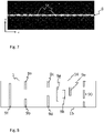
- Fig. 7 depicts the intensity distribution along focus line 8 of laser beam 5 according to the embodiment of fig. 6a), 6b) .
- focus line 8 of laser beam 5 according to the embodiment of fig. 6a), 6b) .
- intensity maxima 54 are induced by interference of partial beams 50, 51.
- Fig. 8 shows, by way of example, schematically and not drawn to scale different shaped flaws 9 formed within glass element 1 according to embodiments of the disclosure
- two coaxially oriented filament-shaped flaws 9a, 9b are generated by irradiation of laser beam 5 (not shown).
- Two coaxially oriented flaws 9a, 9b may, for example, be produced by irradiation glass element 1 at different depths, by using the method of DE 10 2018 126 381 A1 or by a chromatic filamentation method as described in DE 10 2017 208 290 A1 .
- a chromatic filamentation method a lens having chromatic aberration is used to focus the laser beam. Using different wavelength bands, the laser beam then can be focused in different depths to generate the coaxially oriented filaments.
- suitable laser light source may be a white laser, such as a white fiber laser, or any suitable polychromatic laser may be employed.
- a pulsed polychromatic laser beam having in particular a certain pulse duration and having certain wavelengths of the laser beam
- by means of the optical arrangement having chromatic aberration for wavelength-dependent focusing of the laser beam and having at least one filter for wavelength-dependent filtering of the laser beam it is possible to produce a focal line along the beam direction of the workpiece, such as a glass element 1 with which the processing depth of the workpiece may be adjusted selectively and accurately.
- the length of the focal line may be adjusted by generating different foci.
- filter polychromatic light so that a suitable wavelength range may be employed.
- At least one wavelength of the laser beam may be selectively filtered, so that selectively no focus is formed at least at a particular position in the focal line.
- a filter By means of a filter, at least one wavelength of the laser beam may be selectively filtered, so that selectively no focus is formed at least at a particular position in the focal line.
- by unilateral or bilateral limiting of the optical spectrum introduction of a band edge filter, or bandpass filter, it is possible to define a start or end point of the focal line.
- the endpoint is adjusted in a defined way, for example to avoid processing of a support on which the workpiece is resting.
- coaxially oriented flaws 9a, 9b are each starting at opposite end faces 14 and 15 and end vis-à-vis within glass element 1. This may, for example, be accomplished by first irradiating a first side face, for example side face 14, thereby producing a first flaw, and subsequently irradiating the second side face 15, thereby creating a second flaw.
- first irradiating a first side face for example side face 14, thereby producing a first flaw
- second side face 15 thereby creating a second flaw.
- this requires a very precise control of the element position with respect to that of laser beam 5 in two different process steps, wherein the element position is changed between steps, that is, changing the orientation of side faces 14 and 15 relative to laser 7.
- German patent application DE 10 2018 126 381 A1 which allows to produce both flaws in a single process step.
- a suitable focussing optics 70 such as an axicon (for example an axicon without a tip), may be used. Further, it is possible in this case to select the axicon so that interference angle 55 (depicted in fig. 6 ) of partial beam 50 may be adjusted.
- a periodicity that is, the distance between maxima 54 of laser beam 5
- a periodicity that is, the distance between maxima 54 of laser beam 5
- the method according to the disclosure is suited for creating holes or channels with tapering walls in very thin glass elements, that is, glass element with a thickness of 1 mm or less, preferably 0,5 mm or less, particularly preferably 300 ⁇ m or less, more particularly preferably 200 ⁇ m or less, such as 100 ⁇ m or less or even 50 ⁇ m or less or 30 ⁇ m or less.
- coaxially oriented flaws may be produced by irradiating the laser beam subsequently with different focal positions or focal lengths, respectively.
- coaxially oriented flaws 9c, 9d are produced in glass element with each flaw 9c, 9d having a different length so that by etching and widening of filament-shaped flaws 9c, 9d, wall 6 connecting opposite side faces 14, 15 of glass element 1 is formed, wherein a boundary line 12 is formed with different taper angles at the vertices 16, 17, 18, 19 to side faces 14, 15. That is, simple by adjusting the length and/or the position of flaws 9, taper angles 94 may be adjusted. For example, with respect to flaws 9e, 9g, and 9h in fig.
- the present invention also relates to a method of producing channels 10 in plate shaped glass element 1, in particular according to any of previously described embodiments, wherein a pulsed laser beam 5 of an ultrashort pulse laser 7 is directed onto glass element 1, wherein glass element 1 is transparent for laser beam 5 and wherein at least one filament-shaped flaw 9 (for example and with respect to fig.
- flaw 9g is produced in the glass element 1, the filament-shaped flaw 9 (here, filament shaped flaw 9g) extending transversely to side faces 14, 15 of glass element 1, the filament-shaped flaw 9 (here flaw 9g) being produced with laser beam 5 that is concentrated by means of focusing optics 70 to form focus line 8 in glass element 1, wherein the intensity of laser beam 5 within focus line 8 is sufficient to produce the filament-shaped flaw 9, and wherein focus line 8 is adjusted so that both ends of filament shaped flaw 9 are positioned within glass element 1.
- glass element 1 is exposed to etching bath 81 which removes glass by etching, so that so that glass material of the side faces 14, 15 is removed and at least one of the ends of the filament-shaped flaw 9 (here, as pointed out above, flaw 9g) is exposed, and wherein the etching is continued so that the filament shaped flaw 9 is widened to form a channel 10 having a predetermined diameter.
- At least two filament shaped flaws 9 are introduced into glass element 1, here, in fig. 8 , flaws 9g and 9h.
- the ends of the filament shaped flaws 9g, 9h have a different distance to one of side faces 14, 15 of glass element 1 so that upon etching one of the filament shaped flaws 9g, 9h, that is, in the exemplary embodiment illustrated in fig. 8 , flaw 9g in this case, is exposed earlier than the other filament shaped flaw, here flaw 9h, so that the flaws 9g, 9h are exposed to etching bath 81 for different time spans so that channels 10 of different diameter are produced.
- flaws 9 generated within glass element 1 may be adjusted according to a predefined value. For example, as can be seen in the schematic and not drawn to scale depiction of fig. 8 , it may be provided to generate flaws 9 with different diameters, which may be achieved by adjusting the laser parameters and/or by irradiating a flaw longer or repeatedly in order to achieve a greater diameter of the resulting flaw.
- a channel 10 may be formed in that way, wherein the angles drawn between channel 10 (or rather, boundary lines 12 of wall 6 of channel 10) and side faces 14, 15 differ from each other.
- a glass element 1 comprising channels 10 with different taper angles at different vertices 16, 17, 18, 19 is depicted schematically and not drawn to scale in fig. 9 .
- three channels 10a, 10b, and 10c all differ from each other with respect to their respective shape and taper angles.
- boundary line 12 of wall 6 of channel 10a is a straight line, so that channel 10a may also be understood as having the shape of a truncated oblique cone.
- Channel 10b has a tilted boundary line 12, that is, the diameter of channel 10b is wider at openings 60, 61, than in a middle region of channel 10b.
- channel 10c has boundary lines 12 that are concavely curved at least at least one section thereof with respect to perpendicular 13 (not indicated here) to side faces 14, 15.
- channel 10d has straight portion 62, that is, a portion wherein the wall is in parallel to the perpendicular, whereas close to surfaces 14, 15 of glass element 1, wall 12 tapers, such that the portions of channel 10d between portion 62 and surfaces 14, 15 exhibit a truncated cone-like shape.
- a channel 10 d comprising straight portion 62 may, for example, be obtained by etching a series of filament-shaped flaws 9, such as series 90 depicted in fig. 8 .
- filament-shaped flaw 9e is produced by irradiation of laser beam 5, wherein flaw 9e starts and ends within glass element 1.
- laser beam 5 is advanced relative to glass element 1 along predefined path 11.
- a multitude of flaws 9 results that are arranged side-by-side along path 11.
- etching is continued at least until adjacent channels 10 combine so that glass element 1 is divided into segments 100, 101 (shown schematically and not drawn to scale in fig. 10 ) along path 11 and in such a way that walls 6 produced by etching form edge faces 105 of segments 100, 101.
- Such an embodiment is favourable, as in that way, removal of segments may be achieved much easier, especially in case predefined path 11 is a closed line within glass element 1. Further, resulting edges faces 105 are bevelled, which increases the mechanical strength of segments 100, 101.
- laser beam 5 is guided relative to glass element 1 along a closed path 11 so that by subsequent etching an inner glass segment 100 is parted from outer glass segment 101, leaving an opening 102 in outer glass segment 101.
- This is schematically and not drawn to scale depicted in figs. 10 and 11, fig. 11 showing outer glass segment 101 with removed inner glass segment 100, thereby leaving opening 102.
- taper angle 94 between boundary line 12 of wall 6 and side face 14 and/or 15 is adjusted by selecting the molarity of the etching bath (or etching medium) 81. That is, it is possible to vary the taper angle by careful selection of the etching conditions, in particular, by adjusting the etching bath molarity.
- a basic etching bath or an etching medium
- an etching bath or etching medium comprising, as main component, KOH.
- Such an etching bath or etching medium is well suited for etching glasses that are commonly used in technical applications, such as glasses for interposers.
- borosilicate glasses may be etched using basic etching bathes (or basic etching media) comprising KOH.
- basic etching bathes or basic etching media
- acid etching media for glasses that usually are based on HF or related compounds, need not be employed.
- HF comprising and like etching media are harmful, especially with regard to safety and environmental issues.
- taper angle 94 is adjusted by increasing the basic etching bath molarity (or basic etching medium molarity). This is favourable as in this way, the overall reaction rate is increased.
- taper angle 94 for example a taper angle of the edges of segments 100, 101, may be increased by at least 0.1° by increasing the molarity of the basic etching bath or etching medium 81 by 2 mol/1.
- taper angle 94 for example taper angle 94 of edges of segments 100, 101, may be increased in a range from 0.3° to 0.7° by increasing the molarity of the etching bath 81 (or etching medium 81) by a value of from 4 mol/l to 8 mol/1, preferably by increasing the molarity of KOH by 6 mol/1.
- plate shaped glass element 1 may be produced or is produced or producible with a method according to embodiments of the present disclosure.
- Fig. 5 shows by way of example plate-shaped glass element 1 having two opposite side faces 14, 15 and a multitude of etched channels 10. Channels 10 extend through glass element 1 so that walls 6 of channels 10 connect side faces 114, 15. Boundary lines 12 of walls 6 are tapered at vertices 16, 17, 18, 19 between wall 6 and adjacent side faces 14, 15. That is, taper angles 94 (not indicated in fig. 5 ) are drawn between wall 6 (or boundary line 12 of wall 6) and perpendicular 13 (not indicated here) of side faces 14, and 15, respectively. Taper angles 94 may be controlled by a method according to embodiments of the disclosure.
- At least taper two taper angles 94 between boundary lines 12 and the perpendicular 13 of side faces 14, 15 differ from each other.
- At least one of channels 10 has a wall 6 with boundary line 12 that has different taper angles to the perpendicular 13 of side faces 14, 15 at openings 60, 61 of channel 10 to the respective side faces 14, and 15.
- boundary lines 12 of walls 6 at openings 60, 61 of channels 10 of side faces 14, 15 differ from each other.
- wall 6 is concavely curved with respect to a direction perpendicular 13 to side faces 14, 15.
- a multitude of channels 10 is distributed over glass element 1 in a predefined pattern.
- the predefined pattern may constitute a grid, or a circle, or a spiral.
- glass element 1 has a thickness of at most 200 ⁇ m and preferably at least 3 ⁇ m, more preferably at least 5 ⁇ m and most preferably at least 10 ⁇ m.
- Such glass elements 1 and/or segments 100, 101 may for example be used in printed circuit applications, microfluidic devices or for liquid lenses.
Landscapes
- Physics & Mathematics (AREA)
- Optics & Photonics (AREA)
- Engineering & Computer Science (AREA)
- Plasma & Fusion (AREA)
- Mechanical Engineering (AREA)
- Chemical & Material Sciences (AREA)
- Organic Chemistry (AREA)
- Materials Engineering (AREA)
- General Chemical & Material Sciences (AREA)
- Geochemistry & Mineralogy (AREA)
- Chemical Kinetics & Catalysis (AREA)
- Life Sciences & Earth Sciences (AREA)
- Health & Medical Sciences (AREA)
- Toxicology (AREA)
- Laser Beam Processing (AREA)
- Surface Treatment Of Glass (AREA)
- Re-Forming, After-Treatment, Cutting And Transporting Of Glass Products (AREA)
Abstract
The invention relates to a method of structuring a glass element (1), wherein
- a pulsed laser beam (5) of an ultrashort pulse laser (7) is directed onto the glass element (1), wherein
- the glass element (1) is transparent for the laser beam (5) and wherein
- at least one filament-shaped flaw (9) is produced in the glass element (1), the filament-shaped flaw (9) extending transversely to the side faces (14, 15) of the glass element (1), the filament-shaped flaw (9) being produced with a laser beam (5) that is concentrated by means of a focusing optics (70) to form a focus line (8) in the glass element (1), wherein the intensity of the laser beam (5) within the focus line (8) is sufficient to produce the filament-shaped flaw (9), and wherein
- the focus line (8) is adjusted so that the filament shaped flaw (9) ends within the glass element (1), and wherein
- the glass element (1) is exposed to an etching bath (81) which removes glass by etching, so that
- the filament-shaped flaw (9) widens to form a wall (6) extending between the opposite side faces (14, 15) of the glass element (1), the wall (6) having a boundary line (12) that is tapered at the vertex (16, 17, 18, 19) between the wall (6) and an adjacent side face (14, 15), with a taper angle (94) with respect to the perpendicular (13) of the side face (14, 15),
- the taper angle (94) being adjusted by at least one of the position and intensity distribution of the focus line (8).
A further aspect of the invention relates to glass elements (1) produced or producible with a method according to the invention.
Description
- The invention relates in general to a method of structuring a glass element. Further aspects of the invention relate to a structured glass element, in particular a glass element produced or producible by the method according to embodiments of the invention, and the use of such a glass element. In particular, the invention relates to a method for structuring a glass element using a pulsed laser beam of an ultrashort pulse layer, and to glass elements produced or producible by such a method, as well as their use.
- Methods for processing workpieces using an ultrashort pulse layer are frequently employed, for example, in order to prepare a workpiece for separation.
- For example,
WO 2012/006736 A2 discloses a method for preparing a substrate for separation by using an ultrashort pulse laser, i.e. a laser with pulse lengths shorter than 100 ps. In the method disclosed byWO 2012/006736 A2 , several spaced apart filaments are produced along an intended separation line, exploiting a nonlinear effect of selffocusing. -
WO 2017/009379 A1 describes a further development of the method ofWO 2012/009736 A2 . In the method according toWO 2017009679 A1 , modifications are produced in the workpiece extending obliquely to the surfaces of the processed substrate. This is achieved by directing the laser pulses obliquely onto the surface of the respective workpiece. - From
EP 2 931 467 B1 it is known to include the ambient atmosphere as a further process parameter in order to prevent premature self-cleaving due to subcritical crack growth. - Furthermore,
DE 10 2015 116 848 A1 describes the introducing of a zone of defined strength by producing a filament using spherical aberration of a lens in which the Gaussian beam of the ultra-short pulsed laser is converted into a line focus with uneven intensity distribution along the optical axis. - Further,
DE 10 2018 126 381 A1 relates to a method for introducing a separation line into a transparent brittle material and an element thus obtained. - However, all these methods are directed towards separating a workpiece. That is, several material modifications are generated in a workpiece using an ultrashort pulse layer, wherein the modifications are arranged along a predefined path along an intended separation line. Preferably, the material modifications lead to holes formed within the workpiece. Separation may then advantageously be achieved by exposing the workpiece to an etching medium or etching bath so that the holes are widened until adjacent holes or channels combine. In that way, the workpiece may be separated along the predefined path of material modifications (or filaments) formed in the workpiece.
- However, for several applications, it may be preferred to structure a glass element rather than separate it, for example if the glass element is used as an interposer. Further, known methods for producing filaments that are at an oblique angle to the surfaces of the workpiece require extensive process control in order to adjust and monitor, for example, laser parameters and/or workpiece positioning very precisely, for example, by providing special focusing optics that may compensate for astigmatic deformation of the beam profile.
- Therefore, there is a need for a process as well as glass elements thus producible that overcome the drawbacks of the state of the art at least partially.
- It is an object of the present invention to provide for a method of structuring a glass element that overcomes known drawbacks of the state of the art, that is, methods requiring extensive process control, at least partially. A further aspect of the present invention is directed towards a structured glass element as well as to the use of such a glass element.
- This object is achieved by the subject-matter of the independent claims. Advantageous embodiments and refinements are specified in the dependent claims, the drawings and the description.
- The invention therefore relates to a method of structuring a glass element. According to this structuring method, a pulsed laser beam of an ultrashort pulse laser is directed onto the glass element. The glass element is transparent for the laser beam and at least one filament-shaped flaw is produced in the glass element, the filament-shaped flaw extending transversely to the side faces of the glass element. The filament-shaped flaw is produced with a laser beam that is concentrated by means of a focusing optics to form a focus line in the glass element, wherein the intensity of the laser beam within the focus line is sufficient to produce the filament-shaped flaw. The focus line is adjusted so that the filament shaped flaw ends within the glass element. The glass element is exposed to an etching medium or an etching bath which removes glass by etching, so that the filament-shaped flaw widens to form a wall extending between the opposite side faces of the glass element, the wall having a boundary line that is tapered at the vertex between the wall and an adjacent side face, with a taper angle with respect to the perpendicular of the side face, the taper angle being adjusted by at least one of the position, the length and the intensity distribution of the focus line. These parameters can be combined to adjust the geometry of the filament shaped flaws, such as the depth of a flaw in form of a blind hole.
- Such a method offers several advantages.
- According to the method of the present disclosure, a structured glass element is obtained, wherein a filament-shaped flaw is formed that ends within the glass element. In a further process step, this filament-shaped flaw is widened by use of an etching medium or etching bath to form a wall extending between the opposite side faces of the glass element. In other words, by etching, a hole is obtained within the glass element, this hole follows the form of the previously formed filament-shaped flaw at least essentially. As the filament-shaped flaw ends within the glass element, therefore, a blind hole is obtained within the glass element.
- Here, the expression "the hole following the form of the flaw at least essentially" is understood to mean that the hole extends along the length of the previous filament-shaped flaw and is therefore formed as an elongate hole but may, however, be wider and longer than the flaw itself.
- The filament-shaped flaw extends transversely to the side faces, that is, the filament-shaped flaw and the side faces of the glass element draw an angle. In other words, the filament-shaped flaw is not parallel to either side face of the glass element. Preferably, the flaw may draw a right angle with at least one of the side faces of the glass element or may be oriented essentially perpendicular to at least one of the side faces of the glass element. Here, "being oriented at least essentially perpendicular" is understood to mean that the flaw and the normal of the respective side face draw an angle of not more than ±5°.
- However, and quite surprisingly, upon etching of the glass element in order to widen the filament-shaped flaw so that a wall (or a hole with a wall) is formed within the glass element, a wall (or hole having a wall) is obtained with a tapering boundary line. That is, the hole is at an oblique angle to at least one of the side faces. In particular, the angle drawn between the flaw and a side face may differ from the angle drawn between the hole (or the boundary line of the wall of the hole).
- This may achieved quite surprisingly by adjusting at least one the position and/or the intensity distribution of the focus line of the laser beam. However, controlling the position of the substrate orientation relative to the laser beam very precisely, for example, by providing supplemental optical devices such as a cylindrical lens or the like is not necessary. The disclosure therefore provides a simple process for forming structured glass elements having at least one blind hole formed within the glass element, wherein the boundary line of the wall of the hole the side face of the glass elements to which the hole opens draw an oblique angle.
- In the scope of the present invention, the following definitions apply:
A filament is understood to refer to an elongate structure, that is, a structure with a dimension along a first direction of a Cartesian coordinate system that is greater by at least one order of magnitude than the dimensions of the structure along the two further directions of the Cartesian coordinate system that are perpendicular to the first direction. - A flaw may, according to the present disclosure, be understood as an altered region within a workpiece (or glass element). That is, in the region the properties differ from that of the workpiece (or glass element) prior to forming the flaw.
- A filament-shaped flaw therefore may be understood as an altered, elongate region within the glass element.
- A plate-shaped element (or body) is understood to refer to a body whose dimension along a first direction of a Cartesian coordinate system is smaller by one order of magnitude than the dimensions along the two further directions of the Cartesian coordinate system perpendicular to the first direction. For example, a plate shaped glass element may also be denoted a glass plate or a glass ribbon. The plate-shaped element according to the disclosure may be formed as a flat or bend element. Further, in case of a flat element, the side faces may preferably be essentially parallel to each other, that is, the normals or perpendiculars of the side faces drawing an angle of preferably not more than 10°, in particular not more than 5°.
- An ultrashort pulse laser is understood as a laser with a pulse length not more than 100 ps. Preferably, pulse lengths are not longer than 10 ps, more preferably not longer than 1 ps or even smaller than 1 ps.
- According to an embodiment, a channel is produced by etching and widening of the filament-shaped flaw, wherein the channel opens to both opposite side faces. That is, with other words, a through hole is formed according to an embodiment. Such an embodiment may be advantageous in case the glass element is used as an interposer, for example, in printed circuit applications.
- According to a further development, a filament-shaped flat is produced that ends in the glass element by using a focusing optics which superimposes at least two partial beams of the laser beam so that the interference of the partial beams generates an intensity variation along the focus line. This is a very simple, yet effective way to generate a flaw (or material modification) in a workpiece. In this respect, the flaw may also be referred to as a "blind flaw". Further, upon superimposing the two partial beams, thereby generating an intensity variation along the focus line, the resulting angle between the side face of the glass element and the boundary line of the wall may be adjusted in a very simple way.
- According to an embodiment, a multitude of filament-shaped flaws that are distributed over the glass element in a predefined pattern are produced. Further, these filament-shaped flaws may, upon etching, be formed by widening of the flaws. In this way, a multitude of channels that correspond to the previously produced flaws within the glass element and that are distributed over the glass element in a predefined pattern are produced.
- The disclosure further relates to a glass element, in particular a glass element that is produced or at least producible with a method according to an embodiment of the disclosure, preferably a plate-shaped glass element. The glass element comprises two opposite side faces and a multitude of etched channels that extend through the glass element so that the walls of the channels connect the side faces. The boundary lines of the channel walls are tapered at the vertices between the wall and the adjacent side faces. Preferably, at least two taper angles between the boundary lines and the perpendicular of the side faces at the vertices between the walls and the side face differ from each other.
- The invention will now be further explained with reference to the figures. In the figures, like reference numerals refer to the same or corresponding elements.
-
Fig. 1 shows schematically and not drawn to scale the structuring of a glass element according to the method of the disclosure. Using anultrashort pulse laser 7, pulsed laser beam 5 is generated and directed ontoglass element 1.Glass element 1 is transparent for laser beam 5. Here,glass element 1 is a plate shaped, even glass element, however, it is to be understood that according to the disclosure, any glass element may be structured, for example, a plate shape, bend glass element.Glass element 1 has two side faces 14, 15. Side faces may be understood in the scope of the disclosure as relating to principal faces of a body, that is, surfaces that together make up more than 50% of the total of the surface of the respective body. - Further, apart from glass elements, workpieces comprising or consisting of materials other than glass may also be structured by the method of the disclosure.
- At least one filament shaped, that is elongated,
flaw 9, for example a material modification, is produced inglass element 1.Flaw 9 extends transversely to side faces 14, 15 ofglass element 1, that is, an angle is drawn betweenflaw 9 and either of side faces 14, 15. In other words,flaw 9 is not parallel to either of side faces 14, 15. - Laser beam 5 used to produce
flaw 9 is concentrated by means of focusingoptics 70 to form focus line 8 (not shown here) inglass element 1. The intensity of laser beam 5 within focus line 8 (not shown here) is sufficient to produce filament-shapedflaw 9. - Furthermore, focus line 8 (not shown here) is adjusted so that filament-shaped
flaw 9 ends withinglass element 9. -
Fig. 1 further depicts positioning means 20 and computing means 71. Computing means 71 may be used to adjust the power output of laser 5 and/or to control the position ofglass element 1 by controlling position means 20. Positioning means 20 may advantageously be employed in case a multitude of filament-shapedflaws 9 are to be produced inglass element 1, for example along a predefined path. However, it is of course possible to use several computing means 71. -
Fig. 2 depicts schematically and not drawn to scaleglass element 1 according to an embodiment. Here, a multitude of filament-shapedflaws 9 are generated withinglass element 1 by advancing laser beam 5 relative toglass element 1 alongpredefined path 11. In that way, a multitude offlaws 9 results that are arranged side-by-side alongpath 11, that is, in a predefined pattern. The predefined pattern may be a grid, or a sequence of flaws forming a circle or ellipsoid or any other suitable shaped, for example, a spiral shape. As has already been explained with respect tofig. 1 depicting positioning means 20, advancing laser beam 5 alongpath 11, thus resulting in forming a multitude offlaws 9 distributed overglass element 1 in a predefined pattern may be achieved by positioning means 20. - After laser treatment as described above,
glass element 1 comprising at least one filament-shapedflaw 9 is then transferred to anetching tank 80 as schematically and not drawn to scale depicted infig. 3 , whereglass element 1 is exposed to an etching bath 81 (etching medium 81) which removes material ofglass element 1, that is, glassy material or altered glassy material, such as material forming filament-shapedflaw 9, by etching.Etching bath 81 may be an acid etching bath, or else be a basic etching bath. Due to environmental and safety issues, however, a basic etching bath might be preferred. According to the example depicted schematically and not drawn to scale infig. 3 ,glass element 1 comprises a multitude of filament-shapedflaws 9 that are arranged alongpath 11. However, in general, without being restricted to the example shown infig. 3 , it is understood thatglass element 1 need only comprise a single filament-shapedflaw 9. An example ofglass element 1 comprising only a single filament-shaped flaw is shown schematically and not drawn to scale infig. 12 in a top view. Further,glass element 1 may comprise a plurality of single filament-shapedflaws 9 distributed overglass element 1, as shown schematically and not drawn to scale infig. 13 . Further, it is to be noted here that even thoughfig. 2 ,12 and13 show glass elements 1 comprising at least oneflaw 9, as the position of flaw orflaws 9 corresponds to the position of ablind hole 91 or achannel 10 obtained via etching,fig. 2 ,12 and13 may also be understood to refer to glass elements withholes 91 orchannels 10 instead offlaws 9. Further, in case ofglass element 1 offig. 13 , comprising several flaws 9 (or channels or holes), it may be contemplated to arrangeflaws 9 in such a way that resulting holes are arranged in a grid or pattern. This may be particularly preferred incase glass element 1 is used as an interposer. - By etching, filament-shaped
flaw 9 widens to formwall 6, as is depicted schematically and not drawn to scale infig. 4 . That is, by etching, the material offlaw 9 is more easily removed than the unaltered material ofglass element 1, so that by etching,hole 91 is formed corresponding toprevious flaw 9, whereinhole 91 has awall 6.Wall 6 hasboundary line 12 that is tapered atvertex 16 betweenwall 6 andadjacent wall face 14, in the case depicted infig. 4 . Therefore,taper angle 94 is drawn between perpendicular 13 ofside face 14 andwall 6. Thistaper angle 94 is adjusted by at least one of the position, the length and the intensity distribution of thefocus line 8. For example, by adjustment of the position and length of thefocus line 8, the depth of a filament shaped flaw in the form of a blind hole can be adjusted. As shown infig. 4 , resultinghole 91 is a blind hole, that is, a hole ending withinglass element 1. It is noted here that for the sake of better visibility, the diameter ofhole 91 has been exaggerated. Due to etching,hole 91 results, wherein the lateral dimension ofhole 91 is smaller towards a bulk region ofglass element 1. This is due to the etching bath being altered (or aged) during the etching, such that an etching rate at thesurface 14 ofglass element 1 is higher than an etching rate in a bulk region. - As an advantage of the method according to the disclosure, by adjusting position and intensity of
focus line 8, preferably by aid of a suitable focusingoptics 70,taper angle 94 may be controlled and adjusted according to a predefined value in a very simple and efficient way. - A
suitable focussing optics 70 may comprise a lens, such as a spheric or aspheric lens, or an axicon, or a spatial light modulator or suitable combinations thereof. - According to an embodiment as shown schematically and not drawn to scale in
fig. 5 , channel (or through hole) 10 is produced by etching and widening offlaw 9,channel 10 opening to both opposite side faces 14, 15 ofglass element 1. Such a through hole orchannel 10 may be obtained by etching a blind hole that extends from one surface, here surface 15, ofglass element 1 and nearly percolatesglass element 1. A flaw suited for obtaining a channel as shown infig. 5 is, for example, schematically and not drawn to scale depicted asflaw 9f infig. 8 . Such an embodiment may be favourable incase glass element 1 is used in printed circuit applications. As schematically and not drawn to scale depicted infig. 5 , a multitude ofchannels 10 that are distributed overglass element 1 in a predefined pattern may be produced by introducing filament-shapedflaws 9 acrossglass element 1. Generally, however, without being restricted by the example shown here, it is possible to produce only onechannel 10 withinglass element 1. - Very advantageously, according to an embodiment, filament-shaped
flaw 9 that ends inglass element 1 is produced using focusingoptics 70, wherein focusingoptics 70 superimposes at least twopartial beams partial beams focus line 8. In this way,taper angle 94 may be adjusted in a quick and easy manner.Fig. 6 schematically depicts laser beam 5 comprising twopartial beams Fig. 6 a ), laser beam 5 is depicted along the beam direction. As can be seen infig. 6a ),partial beam 51 is a central beam, whereaspartial beam 50 is, in the exemplary embodiment offig. 5 , an annular beam. Infig 6b ), laser beam 5 in a side view.Partial beams region 52 with alength 53. In thisintereference region 52, the filament-shaped flaws may advantageously be produced withinglass element 1. It is noted here that according to the exemplary embodiment as depicted infig. 6a), b ), annularpartial beam 50 may be a Bessel beam or Bessel-Gauß beam. Such partial beams may be created with a suitable focussing optics 70 (not shown here), for example an axicon. -
Fig. 7 depicts the intensity distribution alongfocus line 8 of laser beam 5 according to the embodiment offig. 6a), 6b) . Alongfocus line 8, several intensity maxima 54 are induced by interference ofpartial beams -
Fig. 8 shows, by way of example, schematically and not drawn to scale different shapedflaws 9 formed withinglass element 1 according to embodiments of the disclosure - According to an embodiment and as schematically and not drawn to scale depicted in
fig. 8 by way of example, two coaxially oriented filament-shapedflaws flaws irradiation glass element 1 at different depths, by using the method ofDE 10 2018 126 381 A1DE 10 2017 208 290 A1glass element 1 with which the processing depth of the workpiece may be adjusted selectively and accurately. In particular, the length of the focal line may be adjusted by generating different foci. Further, it is also possible to filter polychromatic light so that a suitable wavelength range may be employed. By means of a filter, at least one wavelength of the laser beam may be selectively filtered, so that selectively no focus is formed at least at a particular position in the focal line. In particular, by unilateral or bilateral limiting of the optical spectrum (introduction of a band edge filter, or bandpass filter), it is possible to define a start or end point of the focal line. In a separate embodiment, in particular the endpoint (on the side facing away from the laser) is adjusted in a defined way, for example to avoid processing of a support on which the workpiece is resting. - As depicted in
fig. 8 , coaxially orientedflaws glass element 1. This may, for example, be accomplished by first irradiating a first side face, forexample side face 14, thereby producing a first flaw, and subsequently irradiating thesecond side face 15, thereby creating a second flaw. However, this requires a very precise control of the element position with respect to that of laser beam 5 in two different process steps, wherein the element position is changed between steps, that is, changing the orientation of side faces 14 and 15 relative tolaser 7. Therefore, it might be preferred to use the method according to Germanpatent application DE 10 2018 126 381 A1 , which allows to produce both flaws in a single process step. In such a method, for example, asuitable focussing optics 70, such as an axicon (for example an axicon without a tip), may be used. Further, it is possible in this case to select the axicon so that interference angle 55 (depicted infig. 6 ) ofpartial beam 50 may be adjusted. For example, if a Nd:YAG-laser (with an emission wavelength of 1064 nm) is used aslaser 7, a periodicity, that is, the distance betweenmaxima 54 of laser beam 5, may be obtained of 10 µm or even less than 10 µm, up to 100 µm or even up to 200 µm. Therefore, the method according to the disclosure is suited for creating holes or channels with tapering walls in very thin glass elements, that is, glass element with a thickness of 1 mm or less, preferably 0,5 mm or less, particularly preferably 300 µm or less, more particularly preferably 200 µm or less, such as 100 µm or less or even 50 µm or less or 30 µm or less. As well, coaxially oriented flaws may be produced by irradiating the laser beam subsequently with different focal positions or focal lengths, respectively. - According to a further embodiment, coaxially oriented
flaws flaw flaws wall 6 connecting opposite side faces 14, 15 ofglass element 1 is formed, wherein aboundary line 12 is formed with different taper angles at thevertices flaws 9, taper angles 94 may be adjusted. For example, with respect toflaws fig. 8 , as their positions relative tosurfaces glass element 1 are different, resulting taper angles ofholes 91 orchannels 10 obtained will be different from each other as a result of etching bath ageing. Therefore, the present invention also relates to a method of producingchannels 10 in plate shapedglass element 1, in particular according to any of previously described embodiments, wherein a pulsed laser beam 5 of anultrashort pulse laser 7 is directed ontoglass element 1, whereinglass element 1 is transparent for laser beam 5 and wherein at least one filament-shaped flaw 9 (for example and with respect tofig. 8 ,flaw 9g) is produced in theglass element 1, the filament-shaped flaw 9 (here, filament shapedflaw 9g) extending transversely to side faces 14, 15 ofglass element 1, the filament-shaped flaw 9 (hereflaw 9g) being produced with laser beam 5 that is concentrated by means of focusingoptics 70 to formfocus line 8 inglass element 1, wherein the intensity of laser beam 5 withinfocus line 8 is sufficient to produce the filament-shapedflaw 9, and whereinfocus line 8 is adjusted so that both ends of filament shapedflaw 9 are positioned withinglass element 1. Subsequently,glass element 1 is exposed toetching bath 81 which removes glass by etching, so that so that glass material of the side faces 14, 15 is removed and at least one of the ends of the filament-shaped flaw 9 (here, as pointed out above,flaw 9g) is exposed, and wherein the etching is continued so that the filament shapedflaw 9 is widened to form achannel 10 having a predetermined diameter. - According to an embodiment, at least two filament shaped
flaws 9 are introduced intoglass element 1, here, infig. 8 ,flaws flaws glass element 1 so that upon etching one of the filament shapedflaws fig. 8 ,flaw 9g in this case, is exposed earlier than the other filament shaped flaw, hereflaw 9h, so that theflaws etching bath 81 for different time spans so thatchannels 10 of different diameter are produced. - Further, it may be contemplated to adjust the diameters of
flaws 9 generated withinglass element 1 according to a predefined value. For example, as can be seen in the schematic and not drawn to scale depiction offig. 8 , it may be provided to generateflaws 9 with different diameters, which may be achieved by adjusting the laser parameters and/or by irradiating a flaw longer or repeatedly in order to achieve a greater diameter of the resulting flaw. - Furthermore, a
channel 10 may be formed in that way, wherein the angles drawn between channel 10 (or rather,boundary lines 12 ofwall 6 of channel 10) and side faces 14, 15 differ from each other. Such aglass element 1 comprisingchannels 10 with different taper angles atdifferent vertices fig. 9 . In the exemplary plate shapedglass element 1 as shown schematically and not drawn to scale infig. 9 , threechannels boundary line 12 ofwall 6 ofchannel 10a is a straight line, so thatchannel 10a may also be understood as having the shape of a truncated oblique cone. -
Channel 10b has a tiltedboundary line 12, that is, the diameter ofchannel 10b is wider atopenings channel 10b. - The diameter of
channel 10 c widens towardsopenings channel 10b,channel 10c hasboundary lines 12 that are concavely curved at least at least one section thereof with respect to perpendicular 13 (not indicated here) to side faces 14, 15. - Further,
channel 10d hasstraight portion 62, that is, a portion wherein the wall is in parallel to the perpendicular, whereas close tosurfaces glass element 1,wall 12 tapers, such that the portions ofchannel 10d betweenportion 62 and surfaces 14, 15 exhibit a truncated cone-like shape. Such achannel 10 d comprisingstraight portion 62 may, for example, be obtained by etching a series of filament-shapedflaws 9, such asseries 90 depicted infig. 8 . - According to a further embodiment depicted schematically and not drawn to scale in
fig. 8 , filament-shapedflaw 9e is produced by irradiation of laser beam 5, whereinflaw 9e starts and ends withinglass element 1. - According to a further embodiment, laser beam 5 is advanced relative to
glass element 1 alongpredefined path 11. In that way, a multitude offlaws 9 results that are arranged side-by-side alongpath 11. In that case, etching is continued at least untiladjacent channels 10 combine so thatglass element 1 is divided intosegments 100, 101 (shown schematically and not drawn to scale infig. 10 ) alongpath 11 and in such a way thatwalls 6 produced by etching form edge faces 105 ofsegments predefined path 11 is a closed line withinglass element 1. Further, resulting edges faces 105 are bevelled, which increases the mechanical strength ofsegments glass element 1 along aclosed path 11 so that by subsequent etching aninner glass segment 100 is parted fromouter glass segment 101, leaving anopening 102 inouter glass segment 101. This is schematically and not drawn to scale depicted infigs. 10 and11, fig. 11 showingouter glass segment 101 with removedinner glass segment 100, thereby leavingopening 102. - According to a further embodiment,
taper angle 94 betweenboundary line 12 ofwall 6 and side face 14 and/or 15 is adjusted by selecting the molarity of the etching bath (or etching medium) 81. That is, it is possible to vary the taper angle by careful selection of the etching conditions, in particular, by adjusting the etching bath molarity. Preferably, a basic etching bath (or an etching medium) is used, for example an etching bath (or etching medium) comprising, as main component, KOH. Such an etching bath or etching medium is well suited for etching glasses that are commonly used in technical applications, such as glasses for interposers. Especially, borosilicate glasses may be etched using basic etching bathes (or basic etching media) comprising KOH. In this way, commonly employed acid etching media for glasses, that usually are based on HF or related compounds, need not be employed. This is favourable, as HF comprising and like etching media are harmful, especially with regard to safety and environmental issues. - Preferably,
taper angle 94 is adjusted by increasing the basic etching bath molarity (or basic etching medium molarity). This is favourable as in this way, the overall reaction rate is increased. - It has been found that
taper angle 94, for example a taper angle of the edges ofsegments etching medium 81 by 2 mol/1. - According to a further embodiment,
taper angle 94, forexample taper angle 94 of edges ofsegments - The present invention is further directed to a plate shaped
glass element 1. In particular, plate shapedglass element 1 may be produced or is produced or producible with a method according to embodiments of the present disclosure.Fig. 5 shows by way of example plate-shapedglass element 1 having two opposite side faces 14, 15 and a multitude of etchedchannels 10.Channels 10 extend throughglass element 1 so thatwalls 6 ofchannels 10 connect side faces 114, 15.Boundary lines 12 ofwalls 6 are tapered atvertices wall 6 and adjacent side faces 14, 15. That is, taper angles 94 (not indicated infig. 5 ) are drawn between wall 6 (orboundary line 12 of wall 6) and perpendicular 13 (not indicated here) of side faces 14, and 15, respectively. Taper angles 94 may be controlled by a method according to embodiments of the disclosure. - Preferably, according to an embodiment, at least taper two taper angles 94 between
boundary lines 12 and the perpendicular 13 of side faces 14, 15 differ from each other. - According to a further embodiment, at least one of
channels 10 has awall 6 withboundary line 12 that has different taper angles to the perpendicular 13 of side faces 14, 15 atopenings channel 10 to the respective side faces 14, and 15. - According to a further embodiment,
boundary lines 12 ofwalls 6 atopenings channels 10 of side faces 14, 15 differ from each other. - According to a further embodiment, within at least one section,
wall 6 is concavely curved with respect to a direction perpendicular 13 to side faces 14, 15. - According to a further embodiment, a multitude of
channels 10 is distributed overglass element 1 in a predefined pattern. For example, the predefined pattern may constitute a grid, or a circle, or a spiral. - According to a further embodiment,
glass element 1 has a thickness of at most 200 µm and preferably at least 3 µm, more preferably at least 5 µm and most preferably at least 10 µm. -
Such glass elements 1 and/orsegments Reference numerals 1 Glass element 5 Laser beam 6 Wall 7 Ultrashort pulse laser, laser 8 Focus line of laser beam 5 9, 9a, 9b, 9c, 9d, 9e, 9f, 9g, 9h Filament-shaped flaw, flaw 90 Series of flaws 10, 10a, 10b, 10c, 10d Channel 11 Path 12 Boundary line 13 perpendicular 14, 15 Side faces of glass element 116, 17, 18, 19 Vertices 20 Positioning means 50, 51 Partial beams of laser 5 52 Interference region 53 Length of interference region 54 Intensity maximum 55 Interference angle 60, 61 Openings of channel 1062 Straight portion of channel 10d70 Focussing optics 71 Computing means 80 Etching tank 81 Etching medium, etching bath 91 Blind hole 94 Taper angle 100, 101 Segments of glass element 1102 Opening within segment 100105 Edge of segments
Claims (20)
- A method of structuring a glass element (1), wherein- a pulsed laser beam (5) of an ultrashort pulse laser (7) is directed onto the glass element (1), wherein- the glass element (1) is transparent for the laser beam (5) and wherein- at least one filament-shaped flaw (9) is produced in the glass element (1), the filament-shaped flaw (9) extending transversely to the side faces (14, 15) of the glass element (1), the filament-shaped flaw (9) being produced with a laser beam (5) that is concentrated by means of a focusing optics (70) to form a focus line (8) in the glass element (1), wherein the intensity of the laser beam (5) within the focus line (8) is sufficient to produce the filament-shaped flaw (9), and wherein- the focus line (8) is adjusted so that the filament shaped flaw (9) ends within the glass element (1), and wherein- the glass element (1) is exposed to an etching bath (81) which removes glass by etching, so that- the filament-shaped flaw (9) widens to form a wall (6) extending between the opposite side faces (14, 15) of the glass element (1), the wall (6) having a boundary line (12) that is tapered at the vertex (16, 17, 18, 19) between the wall (6) and an adjacent side face (14, 15), with a taper angle (94) with respect to the perpendicular (13) of the side face (14, 15),- the taper angle (94) being adjusted by at least one of the position, the length and the intensity distribution of the focus line (8).
- The method according to claim 1, wherein a channel (10) is produced by etching and widening of the filament-shaped flaw (9), and wherein the channel (10) opens to both opposite side faces (14, 15).
- The method according to one of the preceding claims, wherein a multitude of channels (10) distributed over the glass element (1) in a predefined pattern is produced by introducing filament-shaped flaws (9) across the glass element (1).
- The method according to one of the preceding claims, wherein a filament shaped flaw (9) ending in the glass element (1) is produced using a focusing optics (70) which superimposes at least two partial beams (50, 51) of the laser beam (5) so that the interference of the partial beams (50, 51) generates an intensity variation along the focus line (8).
- The method according to one of the preceding claims, wherein two coaxially oriented filament shaped flaws (9) are generated by irradiation of the laser beam (5), the coaxially oriented filament shaped flaws (9) starting at the opposite side faces (14, 15) and ending vis-à-vis within the glass element (1).
- The method according to one of the preceding claims, wherein a filament shaped flaw (9) is produced by irradiation of the laser beam (5), the filament shaped flaw (9) starting and ending within the glass element (1).
- The method according to one of the preceding claims, wherein at least two coaxially oriented filament shaped flaws (9) are produced by irradiation with the laser beam (5), wherein the filament shaped flaws (9) have a different length so that by etching and widening of the filament shaped flaws (9), a wall (6) connecting the opposite side faces (14, 15) of the glass element (1) is formed having a boundary line (12) with different taper angles at the vertices (16) to the side faces (14, 15).
- The method according to one of the preceding claims, wherein the laser beam (5) is advanced relative to the glass element (1) along a predefined path (11) so that a multitude of filament-shaped flaws (9) arranged side-by-side are produced along the path (11), and wherein the etching is continued at least until adjacent channels (10) combine so that the glass element (1) is divided into segments (100, 101) along the path (11) and so that the walls (6) produced by the etching form edge faces (105) of the segments (100, 101).
- The method according to one of the preceding claims, wherein the laser beam (5) is guided relative to the glass element (1) along a closed path (11), so that by subsequent etching an inner glass segment (100) is parted from an outer glass segment (101), leaving an opening (102) in the outer glass segment (101).
- The method according to one of the preceding claims, characterized in that a predefined taper angle (94) between the boundary line (12) of the wall (6) and the side face (14, 15) is adjusted by selecting the molarity of the etching bath (81).
- The method according to claim 10,wherein the etching bath (81) is a basic etching bath, wherein preferably the molarity of the basic etching bath is increased.
- The method according to the preceding claim, wherein a taper angle (94) of the edges of the segments (100, 101) is increased at least by 0.1° by increasing the molarity of the basic etching bath (81) by 2 mol/1.
- The method according to any of claims 10 to 12, wherein a taper angle (94) of the edges of the segments (100, 101) is increased in a range from 0,3° to 0,7° by increasing the molarity of the etching bath (81) by a value of from 4 mol/l to 8 mol/1, preferably by increasing the molarity of KOH by 6 mol/1.
- A method of producing channels in a plate shaped glass element, in particular according to one of the preceding claims, wherein- a pulsed laser beam (5) of an ultrashort pulse laser (7) is directed onto the glass element (1), wherein- the glass element (1) is transparent for the laser beam (5) and wherein- at least one filament-shaped flaw (9) is produced in the glass element (1), the filament-shaped flaw (9) extending transversely to the side faces (14, 15) of the glass element (1), the filament-shaped flaw (9) being produced with a laser beam (5) that is concentrated by means of a focusing optics (70) to form a focus line (8) in the glass element (1), wherein the intensity of the laser beam (5) within the focus line (8) is sufficient to produce the filament-shaped flaw (9), and wherein- the focus line (8) is adjusted so that both ends of the filament shaped flaw (9) are positioned within the glass element (1), the glass element (1) is exposed to an etching bath (81) which removes glass by etching, so that so that glass material of the side faces is removed and at least one of the ends of the filament-shaped flaw (9) is exposed, and wherein the etching is continued so that the filament shaped flaw (9) is widened to form a channel (10) having a predetermined diameter.
- The method according to the preceding claim, wherein at least two filament shaped flaws (9) are introduced into the glass element (1), wherein the ends of the filament shaped flaws (9) have a different distance to a side face (14, 15) of the glass element (1) so that upon etching one of the filament shaped flaws (9) is exposed earlier than the other filament shaped flaw (9) so that the flaws (9) are exposed to the etching bath (81) for different time spans so that channels (10) of different diameter are produced.
- A plate shaped glass element (1), in particular produced with a method according to one of the preceding claims, the glass element (1) having two opposite side faces (14, 15) and a multitude of etched channels (10) extending through the glass element (1) so that the walls (6) of the channels (10) connect the side faces (14, 15), and wherein the boundary lines (12) of the walls (6) are tapered at the vertices (16, 17, 18, 19) between the wall (6) and the adjacent side faces (14, 15), wherein preferably the taper angle (94) is controlled by the method according to at least one of the preceding claims.
- A plate shaped glass element (1) according to claim 16, wherein at least two taper angles (94) between the boundary lines (12) and the perpendicular (13) of the side faces (14, 15) at the vertices (16, 17, 18, 19) between the walls (6) and the side faces (14, 15) differ from each other.
- The glass element (1) according to the preceding claim, characterized by at least one of the following features:- at least one of the channels (10) has a wall (6) with a boundary line (12) that has different taper angles (94) to the perpendicular (13) of the side faces (14, 15) at the openings (60, 61) of the channel (10) to the side faces (14, 15),- the boundary lines (12) of the walls (6) at the openings (60, 61) of the channels (10) to one of the side faces (14, 15) differ from each other.
- The glass element (1) according to one of the two preceding claims, wherein within at least one section, the wall (6) is concavely curved with respect to a direction perpendicular (13) to the side faces (14, 15).
- The glass element (1) according to one of the two preceding claims, comprising at least one of the following features:- a multitude of channels (10) is distributed over the glass element (1) in a predefined pattern which preferably constitutes a grid,- the glass element (1) has a thickness of at most 200 µm.
Priority Applications (5)
| Application Number | Priority Date | Filing Date | Title |
|---|---|---|---|
| EP20212702.3A EP4011846A1 (en) | 2020-12-09 | 2020-12-09 | Method of structuring a glass element and structured glass element produced thereby |
| KR1020210172008A KR20220081918A (en) | 2020-12-09 | 2021-12-03 | Method of structuring a glass element and structured glass element produced thereby |
| CN202111489495.5A CN114669861A (en) | 2020-12-09 | 2021-12-08 | Method for structuring a glass element and structured glass element produced thereby |
| JP2021199275A JP2022091732A (en) | 2020-12-09 | 2021-12-08 | Method of structuring glass element and structured glass element produced thereby |
| US17/546,724 US20220176494A1 (en) | 2020-12-09 | 2021-12-09 | Method of structuring a glass element and structured glass element produced thereby |
Applications Claiming Priority (1)
| Application Number | Priority Date | Filing Date | Title |
|---|---|---|---|
| EP20212702.3A EP4011846A1 (en) | 2020-12-09 | 2020-12-09 | Method of structuring a glass element and structured glass element produced thereby |
Publications (1)
| Publication Number | Publication Date |
|---|---|
| EP4011846A1 true EP4011846A1 (en) | 2022-06-15 |
Family
ID=73789895
Family Applications (1)
| Application Number | Title | Priority Date | Filing Date |
|---|---|---|---|
| EP20212702.3A Pending EP4011846A1 (en) | 2020-12-09 | 2020-12-09 | Method of structuring a glass element and structured glass element produced thereby |
Country Status (5)
| Country | Link |
|---|---|
| US (1) | US20220176494A1 (en) |
| EP (1) | EP4011846A1 (en) |
| JP (1) | JP2022091732A (en) |
| KR (1) | KR20220081918A (en) |
| CN (1) | CN114669861A (en) |
Citations (13)
| Publication number | Priority date | Publication date | Assignee | Title |
|---|---|---|---|---|
| WO2012009736A2 (en) | 2010-07-16 | 2012-01-19 | Kyle Gradus-Samson | Electrical connector |
| WO2012006736A2 (en) | 2010-07-12 | 2012-01-19 | Filaser Inc. | Method of material processing by laser filamentation |
| EP2503859A1 (en) * | 2009-12-25 | 2012-09-26 | Fujikura, Ltd. | Through-wired substrate and manufacturing method therefor |
| DE102013103370A1 (en) * | 2013-04-04 | 2014-10-09 | Lpkf Laser & Electronics Ag | Method for introducing perforations into a glass substrate and a glass substrate produced in this way |
| WO2017009679A1 (en) | 2015-07-13 | 2017-01-19 | Otis Elevator Company | Deterrent device inhibition key |
| WO2017009379A1 (en) | 2015-07-15 | 2017-01-19 | Schott Ag | Method and device for removing glass parts or glass ceramic parts |
| DE102015116848A1 (en) | 2015-10-05 | 2017-04-06 | Schott Ag | Dielectric workpiece with a zone of defined strength and method for its production and its use |
| EP2931467B1 (en) | 2012-11-14 | 2017-06-14 | Schott AG | Method for producing aligned linear breaking points by ultra-short focussed, pulsed laser radiation; method and device for separating a workpiece by means of ultra-short focussed laser radiation using a protective gas atmosphere |
| DE102017208290A1 (en) | 2017-05-17 | 2018-11-22 | Schott Ag | Apparatus and method for processing a workpiece along a predetermined processing line |
| WO2018217696A2 (en) * | 2017-05-25 | 2018-11-29 | Corning Incorporated | Articles having vias with geometry attributes and methods for fabricating the same |
| DE102018126381A1 (en) | 2018-02-15 | 2019-08-22 | Schott Ag | Method and device for inserting a dividing line into a transparent brittle material, as well as according to the method producible, provided with a dividing line element |
| US20190329251A1 (en) * | 2018-04-27 | 2019-10-31 | Schott Ag | Method for producing fine structures in the volume of a substrate composed of hard brittle material |
| WO2020224706A1 (en) * | 2019-05-06 | 2020-11-12 | Lpkf Laser & Electronics Ag | Method for producing microstructures in a glass substrate |
-
2020
- 2020-12-09 EP EP20212702.3A patent/EP4011846A1/en active Pending
-
2021
- 2021-12-03 KR KR1020210172008A patent/KR20220081918A/en unknown
- 2021-12-08 CN CN202111489495.5A patent/CN114669861A/en active Pending
- 2021-12-08 JP JP2021199275A patent/JP2022091732A/en active Pending
- 2021-12-09 US US17/546,724 patent/US20220176494A1/en active Pending
Patent Citations (13)
| Publication number | Priority date | Publication date | Assignee | Title |
|---|---|---|---|---|
| EP2503859A1 (en) * | 2009-12-25 | 2012-09-26 | Fujikura, Ltd. | Through-wired substrate and manufacturing method therefor |
| WO2012006736A2 (en) | 2010-07-12 | 2012-01-19 | Filaser Inc. | Method of material processing by laser filamentation |
| WO2012009736A2 (en) | 2010-07-16 | 2012-01-19 | Kyle Gradus-Samson | Electrical connector |
| EP2931467B1 (en) | 2012-11-14 | 2017-06-14 | Schott AG | Method for producing aligned linear breaking points by ultra-short focussed, pulsed laser radiation; method and device for separating a workpiece by means of ultra-short focussed laser radiation using a protective gas atmosphere |
| DE102013103370A1 (en) * | 2013-04-04 | 2014-10-09 | Lpkf Laser & Electronics Ag | Method for introducing perforations into a glass substrate and a glass substrate produced in this way |
| WO2017009679A1 (en) | 2015-07-13 | 2017-01-19 | Otis Elevator Company | Deterrent device inhibition key |
| WO2017009379A1 (en) | 2015-07-15 | 2017-01-19 | Schott Ag | Method and device for removing glass parts or glass ceramic parts |
| DE102015116848A1 (en) | 2015-10-05 | 2017-04-06 | Schott Ag | Dielectric workpiece with a zone of defined strength and method for its production and its use |
| DE102017208290A1 (en) | 2017-05-17 | 2018-11-22 | Schott Ag | Apparatus and method for processing a workpiece along a predetermined processing line |
| WO2018217696A2 (en) * | 2017-05-25 | 2018-11-29 | Corning Incorporated | Articles having vias with geometry attributes and methods for fabricating the same |
| DE102018126381A1 (en) | 2018-02-15 | 2019-08-22 | Schott Ag | Method and device for inserting a dividing line into a transparent brittle material, as well as according to the method producible, provided with a dividing line element |
| US20190329251A1 (en) * | 2018-04-27 | 2019-10-31 | Schott Ag | Method for producing fine structures in the volume of a substrate composed of hard brittle material |
| WO2020224706A1 (en) * | 2019-05-06 | 2020-11-12 | Lpkf Laser & Electronics Ag | Method for producing microstructures in a glass substrate |
Also Published As
| Publication number | Publication date |
|---|---|
| CN114669861A (en) | 2022-06-28 |
| KR20220081918A (en) | 2022-06-16 |
| US20220176494A1 (en) | 2022-06-09 |
| JP2022091732A (en) | 2022-06-21 |
Similar Documents
| Publication | Publication Date | Title |
|---|---|---|
| KR101778418B1 (en) | Method for producing aligned linear breaking points by ultra-short focussed, pulsed laser radiation, and method and device for separating a workpiece by means of ultra-short focussed laser radiation using a protective gas atmosphere | |
| KR102138964B1 (en) | System for asymmetric optical beam shaping | |
| US10522963B2 (en) | Laser cutting of materials with intensity mapping optical system | |
| EP3490945B1 (en) | Methods for laser processing | |
| KR102605322B1 (en) | Method and apparatus for introducing separation lines into transparent brittle fracture materials and members producible by such method and having separation lines | |
| EP1990125B1 (en) | Glass processing method using laser | |
| CN107003530B (en) | Optical system for beam shaping | |
| KR101298019B1 (en) | Laser processing apparatus | |
| CN111065485B (en) | Apparatus and method for laser machining transparent workpieces using an afocal beam adjustment assembly | |
| EP2105239A1 (en) | Light condensing optical system, laser processing method and apparatus, and method of manufacturing fragile material | |
| TW201536461A (en) | Edge chamfering methods | |
| JP2006290630A (en) | Processing method of glass using laser | |
| CN112799236A (en) | Diffractive optical beam shaping element | |
| CN105555463A (en) | Device and process for marking an ophthalmic lens with a pulsed laser of wavelength and energy selected per pulse | |
| WO2021219782A1 (en) | Spacer wafer for producing an electro-optical transducer component, spacer, method for producing such a spacer wafer, and electro-optical transducer component comprising such a spacer | |
| JP2005306702A (en) | Method of forming micro-hole having tapered shape | |
| US20220184744A1 (en) | Method for machining a workpiece | |
| JP2009056467A (en) | Apparatus and method for laser beam machining | |
| EP4011846A1 (en) | Method of structuring a glass element and structured glass element produced thereby | |
| US20230071407A1 (en) | Method for cutting a glass element and cutting system | |
| JP7082615B2 (en) | Electrochromic coated glass articles and how to laser machine them | |
| CN112996627A (en) | Mitigation of low surface quality | |
| CN113321412A (en) | Method for separating a glass component and glass sub-component | |
| WO2017126506A1 (en) | Method for cutting object to be processed | |
| KR102664778B1 (en) | Forming method of high-speed precision through hole using infrared laser |
Legal Events
| Date | Code | Title | Description |
|---|---|---|---|
| STAA | Information on the status of an ep patent application or granted ep patent |
Free format text: STATUS: EXAMINATION IS IN PROGRESS |
|
| PUAI | Public reference made under article 153(3) epc to a published international application that has entered the european phase |
Free format text: ORIGINAL CODE: 0009012 |
|
| 17P | Request for examination filed |
Effective date: 20201209 |
|
| AK | Designated contracting states |
Kind code of ref document: A1 Designated state(s): AL AT BE BG CH CY CZ DE DK EE ES FI FR GB GR HR HU IE IS IT LI LT LU LV MC MK MT NL NO PL PT RO RS SE SI SK SM TR |
|
| RBV | Designated contracting states (corrected) |
Designated state(s): AL AT BE BG CH CY CZ DE DK EE ES FI FR GB GR HR HU IE IS IT LI LT LU LV MC MK MT NL NO PL PT RO RS SE SI SK SM TR |
|
| P01 | Opt-out of the competence of the unified patent court (upc) registered |
Effective date: 20230516 |