EP4006533A1 - Weld zone detection method using thermal image sensing - Google Patents
Weld zone detection method using thermal image sensing Download PDFInfo
- Publication number
- EP4006533A1 EP4006533A1 EP20891574.4A EP20891574A EP4006533A1 EP 4006533 A1 EP4006533 A1 EP 4006533A1 EP 20891574 A EP20891574 A EP 20891574A EP 4006533 A1 EP4006533 A1 EP 4006533A1
- Authority
- EP
- European Patent Office
- Prior art keywords
- weld portion
- temperature
- weld
- busbar
- battery cell
- Prior art date
- Legal status (The legal status is an assumption and is not a legal conclusion. Google has not performed a legal analysis and makes no representation as to the accuracy of the status listed.)
- Pending
Links
- 238000001514 detection method Methods 0.000 title description 5
- 238000000034 method Methods 0.000 claims abstract description 37
- 230000008859 change Effects 0.000 claims abstract description 19
- 230000002950 deficient Effects 0.000 claims abstract description 18
- 238000003466 welding Methods 0.000 claims description 13
- 238000001816 cooling Methods 0.000 claims description 9
- 238000007689 inspection Methods 0.000 abstract description 23
- 238000001931 thermography Methods 0.000 description 8
- 230000020169 heat generation Effects 0.000 description 5
- WHXSMMKQMYFTQS-UHFFFAOYSA-N Lithium Chemical compound [Li] WHXSMMKQMYFTQS-UHFFFAOYSA-N 0.000 description 4
- 230000008901 benefit Effects 0.000 description 4
- 238000005516 engineering process Methods 0.000 description 4
- 229910052744 lithium Inorganic materials 0.000 description 4
- 229910052751 metal Inorganic materials 0.000 description 4
- 239000002184 metal Substances 0.000 description 4
- PXHVJJICTQNCMI-UHFFFAOYSA-N Nickel Chemical compound [Ni] PXHVJJICTQNCMI-UHFFFAOYSA-N 0.000 description 3
- 230000005855 radiation Effects 0.000 description 3
- 230000007547 defect Effects 0.000 description 2
- 238000011161 development Methods 0.000 description 2
- 230000006870 function Effects 0.000 description 2
- 238000010438 heat treatment Methods 0.000 description 2
- 230000007246 mechanism Effects 0.000 description 2
- 150000002739 metals Chemical class 0.000 description 2
- 238000012986 modification Methods 0.000 description 2
- 230000004048 modification Effects 0.000 description 2
- 230000004913 activation Effects 0.000 description 1
- 238000003915 air pollution Methods 0.000 description 1
- OJIJEKBXJYRIBZ-UHFFFAOYSA-N cadmium nickel Chemical compound [Ni].[Cd] OJIJEKBXJYRIBZ-UHFFFAOYSA-N 0.000 description 1
- 239000003086 colorant Substances 0.000 description 1
- 230000000052 comparative effect Effects 0.000 description 1
- 230000008878 coupling Effects 0.000 description 1
- 238000010168 coupling process Methods 0.000 description 1
- 238000005859 coupling reaction Methods 0.000 description 1
- 230000003247 decreasing effect Effects 0.000 description 1
- 230000000694 effects Effects 0.000 description 1
- 239000008151 electrolyte solution Substances 0.000 description 1
- 239000002803 fossil fuel Substances 0.000 description 1
- 230000006872 improvement Effects 0.000 description 1
- 238000002347 injection Methods 0.000 description 1
- 239000007924 injection Substances 0.000 description 1
- 230000003446 memory effect Effects 0.000 description 1
- 229910052759 nickel Inorganic materials 0.000 description 1
- 229910000652 nickel hydride Inorganic materials 0.000 description 1
- QELJHCBNGDEXLD-UHFFFAOYSA-N nickel zinc Chemical compound [Ni].[Zn] QELJHCBNGDEXLD-UHFFFAOYSA-N 0.000 description 1
- 239000011148 porous material Substances 0.000 description 1
- 230000008569 process Effects 0.000 description 1
- 238000011160 research Methods 0.000 description 1
- 239000000243 solution Substances 0.000 description 1
- 238000012546 transfer Methods 0.000 description 1
Images


Classifications
-
- G—PHYSICS
- G01—MEASURING; TESTING
- G01N—INVESTIGATING OR ANALYSING MATERIALS BY DETERMINING THEIR CHEMICAL OR PHYSICAL PROPERTIES
- G01N25/00—Investigating or analyzing materials by the use of thermal means
- G01N25/72—Investigating presence of flaws
-
- B—PERFORMING OPERATIONS; TRANSPORTING
- B23—MACHINE TOOLS; METAL-WORKING NOT OTHERWISE PROVIDED FOR
- B23K—SOLDERING OR UNSOLDERING; WELDING; CLADDING OR PLATING BY SOLDERING OR WELDING; CUTTING BY APPLYING HEAT LOCALLY, e.g. FLAME CUTTING; WORKING BY LASER BEAM
- B23K31/00—Processes relevant to this subclass, specially adapted for particular articles or purposes, but not covered by only one of the preceding main groups
- B23K31/12—Processes relevant to this subclass, specially adapted for particular articles or purposes, but not covered by only one of the preceding main groups relating to investigating the properties, e.g. the weldability, of materials
- B23K31/125—Weld quality monitoring
-
- G—PHYSICS
- G01—MEASURING; TESTING
- G01N—INVESTIGATING OR ANALYSING MATERIALS BY DETERMINING THEIR CHEMICAL OR PHYSICAL PROPERTIES
- G01N33/00—Investigating or analysing materials by specific methods not covered by groups G01N1/00 - G01N31/00
- G01N33/20—Metals
- G01N33/207—Welded or soldered joints; Solderability
-
- H—ELECTRICITY
- H01—ELECTRIC ELEMENTS
- H01M—PROCESSES OR MEANS, e.g. BATTERIES, FOR THE DIRECT CONVERSION OF CHEMICAL ENERGY INTO ELECTRICAL ENERGY
- H01M10/00—Secondary cells; Manufacture thereof
- H01M10/42—Methods or arrangements for servicing or maintenance of secondary cells or secondary half-cells
- H01M10/4285—Testing apparatus
-
- H—ELECTRICITY
- H01—ELECTRIC ELEMENTS
- H01M—PROCESSES OR MEANS, e.g. BATTERIES, FOR THE DIRECT CONVERSION OF CHEMICAL ENERGY INTO ELECTRICAL ENERGY
- H01M10/00—Secondary cells; Manufacture thereof
- H01M10/42—Methods or arrangements for servicing or maintenance of secondary cells or secondary half-cells
- H01M10/48—Accumulators combined with arrangements for measuring, testing or indicating the condition of cells, e.g. the level or density of the electrolyte
- H01M10/486—Accumulators combined with arrangements for measuring, testing or indicating the condition of cells, e.g. the level or density of the electrolyte for measuring temperature
-
- H—ELECTRICITY
- H01—ELECTRIC ELEMENTS
- H01M—PROCESSES OR MEANS, e.g. BATTERIES, FOR THE DIRECT CONVERSION OF CHEMICAL ENERGY INTO ELECTRICAL ENERGY
- H01M50/00—Constructional details or processes of manufacture of the non-active parts of electrochemical cells other than fuel cells, e.g. hybrid cells
- H01M50/50—Current conducting connections for cells or batteries
- H01M50/502—Interconnectors for connecting terminals of adjacent batteries; Interconnectors for connecting cells outside a battery casing
- H01M50/514—Methods for interconnecting adjacent batteries or cells
- H01M50/516—Methods for interconnecting adjacent batteries or cells by welding, soldering or brazing
-
- B—PERFORMING OPERATIONS; TRANSPORTING
- B23—MACHINE TOOLS; METAL-WORKING NOT OTHERWISE PROVIDED FOR
- B23K—SOLDERING OR UNSOLDERING; WELDING; CLADDING OR PLATING BY SOLDERING OR WELDING; CUTTING BY APPLYING HEAT LOCALLY, e.g. FLAME CUTTING; WORKING BY LASER BEAM
- B23K2101/00—Articles made by soldering, welding or cutting
- B23K2101/36—Electric or electronic devices
- B23K2101/38—Conductors
-
- Y—GENERAL TAGGING OF NEW TECHNOLOGICAL DEVELOPMENTS; GENERAL TAGGING OF CROSS-SECTIONAL TECHNOLOGIES SPANNING OVER SEVERAL SECTIONS OF THE IPC; TECHNICAL SUBJECTS COVERED BY FORMER USPC CROSS-REFERENCE ART COLLECTIONS [XRACs] AND DIGESTS
- Y02—TECHNOLOGIES OR APPLICATIONS FOR MITIGATION OR ADAPTATION AGAINST CLIMATE CHANGE
- Y02E—REDUCTION OF GREENHOUSE GAS [GHG] EMISSIONS, RELATED TO ENERGY GENERATION, TRANSMISSION OR DISTRIBUTION
- Y02E60/00—Enabling technologies; Technologies with a potential or indirect contribution to GHG emissions mitigation
- Y02E60/10—Energy storage using batteries
Definitions
- the present invention relates to a weld portion inspection method using thermal image sensing, and more particularly to a weld portion inspection method using thermal image sensing capable of sensing temperature increase and decrease patterns of a weld portion through thermal images and determining whether the weld portion is defective based on the result of analysis thereof.
- secondary batteries which are energy sources substituting for fossil fuels causing air pollution, have been applied to an electric vehicle (EV), a hybrid electric vehicle (HEV), and a plug-in hybrid electric vehicle (P-HEV), and therefore there is an increasing necessity for development of secondary batteries.
- EV electric vehicle
- HEV hybrid electric vehicle
- P-HEV plug-in hybrid electric vehicle
- the lithium secondary battery is in the spotlight, since the lithium secondary battery has little memory effect, whereby the lithium secondary battery is capable of being freely charged and discharged, has a very low self-discharge rate, and has high energy density, compared to the nickel-based secondary batteries.
- a battery module including a plurality of battery cells electrically connected to each other is used in vehicles. Since the plurality of battery cells is connected to each other in series and in parallel, the capacity and output of the battery module are increased.
- a busbar is used for electrical connection between the battery cells.
- busbar and leads of the battery cells are generally connected to each other by welding, since each of the busbar and the leads is an electrically conductive metal.
- Japanese Patent Application Publication No. 2000-131254 discloses technology related to a tab terminal member and a pattern portion of a busbar, which are two metal members welded to each other, the technology being capable of holding the front end of the tab terminal member using a heating jig, transferring heat from the tab terminal member to the pattern portion of the busbar via a weld portion to measure the maximum temperature or temperature distribution at the rear surface of the pattern portion of the busbar using a radiation thermometer, and comparing the measured maximum temperature or the area of a region having a predetermined temperature or higher with a comparative value obtained in advance to determine whether the weld portion is defective.
- the prior art document has an advantage in that it is possible to somewhat determine whether the weld portion is defective without destroying the weld portion.
- separate equipment and power for heat transfer are necessary.
- an inspection apparatus may be complicated and inspection cost based thereon may be increased.
- Patent Document 1 Japanese Patent Application Publication No. 2000-131254
- the present invention has been made in view of the above problems, and it is an object of the present invention to provide a weld portion inspection method capable of accurately determining whether a weld portion is defective.
- the present invention provides a method of inspecting a weld portion between a lead portion of a battery cell and a busbar, wherein the weld portion (300) is heated using Joule heat and whether the weld portion (300) is defective is determined based on a temperature increase pattern of the weld portion (300).
- the Joule heat may be generated by current supplied from the battery cell (100) welded to the busbar (200).
- the battery cell (100) may be in a packed state before shipment.
- the heated weld portion (300) may be cooled and whether the weld portion (300) is defective may be determined based on a temperature decrease pattern of the weld portion (300) .
- the cooling may be performed by interrupting the supply of current from the battery cell (100).
- the temperature increase pattern may be at least one of a time taken until the temperature reaches a specific temperature, a temperature increase rate over time, and the maximum temperature.
- the temperature decrease pattern may be at least one of a time taken until the temperature reaches an initial temperature from a predetermined temperature and a temperature decrease rate over time.
- the temperature increase pattern and/or the temperature decrease pattern may be set for the weld portion and a neighboring region of the weld portion, the weld portion and the neighboring region of the weld portion being divided into a predetermined number of regions.
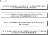
- the method of inspecting the weld portion between the lead portion of the battery cell and the busbar may include a first step of welding lead portions (110) of two or more battery cells (100) and a busbar (200) to form weld portions (300), a second step of turning on a switch such that the battery cells (100) are electrically connected to each other, a third step of continuously measuring a change in temperature of each of the weld portions (300), and a fourth step of determining whether each of the weld portions (300) is defective based on the result of change in temperature.
- the second step may be maintained for a predetermined time after the battery cells (100) are discharged.
- the third step may be performed until the battery cells (100) are discharged.
- a weld portion inspection method using thermal image sensing according to the present invention has an advantage in that whether a weld portion is defective is determined in simultaneous consideration of heat generation characteristics and cooling characteristics of the weld portion, whereby more accurate determination is possible.
- the weld portion inspection method using thermal image sensing according to the present invention has an advantage in that electric power of a battery cell itself to be inspected is used, whereby no separate electric power is necessary and furthermore it is possible to minimize incidental equipment for inspection.
- FIG. 1 is a view showing a configuration for weld portion inspection according to a first preferred embodiment of the present invention.
- a lead portion 110 extending from each of two battery cells 100, a busbar 200 configured to electrically connect the lead portions 110 to each other, a weld portion 300 configured to fix each lead portion 110 and the busbar 200 to each other, and a thermal imaging camera 500 configured to measure a change in temperature of the weld portion 300 are provided.
- the two battery cells 100 are cells to be inspected in order to determine various kinds of performance, such as performance related to the weld portions, for product shipment.
- One side of the busbar 200 is connected to a negative electrode lead extending from one of the battery cells 100 and the other side of the busbar 200 is connected to a positive electrode lead extending from the other battery cell 100, whereby the battery cells 100 may be electrically connected to each other.
- each lead portion 110 and the busbar 200 which are made of metals, are connected to each other by welding, such as resistance welding.
- welding such as resistance welding.
- the weld portion 300 is formed so as to extend from the lead portion 110 to the busbar 200.
- a switch 400 is provided between lead portions of the battery cells 100 that are not connected to the busbar 200, i.e. between a positive electrode lead of the battery cell 100 located on the left side of FIG. 1 and a negative electrode lead of the battery cell 100 located on the right side of FIG. 1 .
- the switch is configured to perform electrical connection or interruption therebetween.
- the thermal imaging camera 500 is installed in the vicinity of the weld portions 300, each of which fixes a corresponding one of the lead portions 110 and the busbar 200 to each other.
- the thermal imaging camera is a camera configured to track and detect heat and to express the heat using different colors based on the temperature thereof, which is technology well known in various fields, and therefore a detailed description of the operating principle or the function thereof will be omitted.
- FIG. 2 is a flowchart illustrating a weld portion inspection method according to a first preferred embodiment of the present invention
- FIG. 3 is a conceptual view illustrating a heat generation mechanism of a weld portion at the time of current application
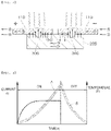
- FIG. 4 is a conceptual view illustrating a change in temperature of a weld portion at the time of current application or interruption
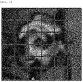
- FIG. 5 is a view showing an example of the temperature distribution image result in a neighboring region including a weld portion.
- the weld portion inspection method includes a first step of welding lead portions 110 of two or more battery cells 100 and a busbar 200 to form weld portions 300, a second step of turning on a switch such that the battery cells 100 are electrically connected to each other, a third step of continuously measuring a change in temperature of each of the weld portions 300, and a fourth step of determining whether each of the weld portions 300 is defective based on the result of change in temperature.
- the first step was described in detail with reference to FIG. 1 , and therefore a duplicate description thereof will be omitted.
- the second step is a step of turning on the switch 400 such that the battery cells 100 are electrically connected to each other. At this time, heat is generated from each weld portion 300.
- Q indicates Joule heat
- I indicates current
- R indicates resistance
- t indicates time
- a separate external power source may be used as a power source configured to generate Joule heat in each weld portion 300.
- a battery cell 100 is completed through an activation step after injection of an electrolytic solution. At this time, the battery cell 100 is charged with a predetermined amount of electric power, and therefore it is advantageous to use the electric power. That is, at the time of using an external power source, not only is a separate power source needed but also additional wiring for electrical connection between the external power source and the bus bar 200 is needed. In contrast, it is possible to overcome the above problem in the case in which electric power charged in the battery cells 100 connected to the bus bar 200 is used.
- the third step which is a step of measuring a change in temperature of each of the weld portions 300, may be performed simultaneously with the second step of electrically connecting the battery cells 100 to each other.
- thermal radiation energy in the vicinity of the weld portion 300 is electronically scanned using the thermal imaging camera 500 to create temperature distribution data for each position based on current application time.
- the temperature of the surroundings including the weld portion is distributed to a plurality of unit regions, and temperature data for each region are secured.
- the fourth step which is a step of determining whether each of the weld portions 300 is defective based on the result of change in temperature, whether the change in temperature is within a normal range is determined by comparison.
- the heated weld portion 300 is left to be cooled down for a predetermined time after the battery cell 100 is completely discharged. In the same manner, whether a temperature decrease pattern of the measured weld portion 300 is changed within a normal range (region B of FIG. 4 ) is determined by comparison in order to determine whether the weld portion is defective.
- Temperature increase occurs as inner heat accumulates within a short time by forced heating due to current application whereas cooling is a phenomenon in which the accumulated heat is naturally transmitted to the inside/outside.
- convection, radiation, and internal conduction through a surface may have different cooling patterns depending on the internal structure of the weld portion, such as the surface state, pores, grain size, and forming structure of the weld portion. Consequently, it is possible to determine the state of the weld portion based on a temperature decrease pattern at the time of cooling.
- a concrete example of the temperature increase pattern may be time taken until the temperature reaches a specific temperature, a temperature increase rate (change in temperature/time), or the maximum temperature.
- the cooling pattern may be time taken until the temperature reaches the original temperature from the maximum temperature or a temperature decrease rate (change in temperature/time).
- each of the temperature increase pattern and the cooling pattern it is preferable to simultaneously utilize a single factor or a plurality of factors. In particular, it is more preferable to apply the factors to all of the plurality of divided regions as shown in FIG. 5 .
- the temperature change distribution result of the weld portion is matched together with macrography and stick inspection, which are generally performed to detect weld defects, in order to secure the temperature change result of the weld portion in a normal state.
- FIG. 6 is a view showing a configuration for weld portion inspection according to a second preferred embodiment of the present invention.
- the second embodiment is identical to the first embodiment except that four battery cells 100 are connected to each other in series and that three busbars 200 are used in order to electrically connect neighboring ones of the battery cells 100 to each other.
- a switch 400 is connected such that current flows, weld portions 300 formed in each busbar 200 are scanned using a thermal imaging camera 500, and temperature data are analyzed, whereby it is possible to determine whether weld portions 300 formed in a specific busbar 200 are defective.
- thermal imaging camera 500 Although a single thermal imaging camera 500 is shown as being used in the figure, a plurality of thermal imaging cameras 500 may be used.
Abstract
Description
- This application claims the benefit of priority to
Korean Patent Application No. 2019-0153866 filed on November 27, 2019 - The present invention relates to a weld portion inspection method using thermal image sensing, and more particularly to a weld portion inspection method using thermal image sensing capable of sensing temperature increase and decrease patterns of a weld portion through thermal images and determining whether the weld portion is defective based on the result of analysis thereof.
- With technological development of mobile devices, such as mobile phones, laptop computers, camcorders, and digital cameras, and an increase in demand therefor, research on secondary batteries, which are capable of being charged and discharged, has been actively conducted. In addition, secondary batteries, which are energy sources substituting for fossil fuels causing air pollution, have been applied to an electric vehicle (EV), a hybrid electric vehicle (HEV), and a plug-in hybrid electric vehicle (P-HEV), and therefore there is an increasing necessity for development of secondary batteries.
- There are a nickel-cadmium battery, a nickel-hydride battery, a nickel-zinc battery, and a lithium secondary battery as currently commercialized secondary batteries. Thereamong, the lithium secondary battery is in the spotlight, since the lithium secondary battery has little memory effect, whereby the lithium secondary battery is capable of being freely charged and discharged, has a very low self-discharge rate, and has high energy density, compared to the nickel-based secondary batteries.
- Meanwhile, several battery cells are disposed in a secondary battery used in small-sized devices, whereas a battery module including a plurality of battery cells electrically connected to each other is used in vehicles. Since the plurality of battery cells is connected to each other in series and in parallel, the capacity and output of the battery module are increased. A busbar is used for electrical connection between the battery cells.
- The busbar and leads of the battery cells are generally connected to each other by welding, since each of the busbar and the leads is an electrically conductive metal.
- Conventionally, there is no technology for detecting all weld defects, such as poor welding and overwelding, at the time of welding therebetween, and therefore improvement in weld quality is limited. That is, in the case in which macrography is performed after resistance welding, partial detection of overwelding is possible, but detection of poor welding is impossible. For stick inspection, in which a welded portion is pulled in order to detect non-welding, partial detection of poor welding or detection of non-welding is possible. In this case, however, force is directly applied to a lead or a busbar, whereby a battery cell may be damaged.
-
Japanese Patent Application Publication No. 2000-131254 - The prior art document has an advantage in that it is possible to somewhat determine whether the weld portion is defective without destroying the weld portion. However, separate equipment and power for heat transfer are necessary. As a result, there is a problem in that an inspection apparatus may be complicated and inspection cost based thereon may be increased.
- (Patent Document 1)
Japanese Patent Application Publication No. 2000-131254 - The present invention has been made in view of the above problems, and it is an object of the present invention to provide a weld portion inspection method capable of accurately determining whether a weld portion is defective.
- It is another object of the present invention to provide a weld portion inspection method capable of determining whether a weld portion is defective without separate external electric power.
- It is a further object of the present invention to provide a weld portion inspection method using simple equipment.
- In order to accomplish the above objects, the present invention provides a method of inspecting a weld portion between a lead portion of a battery cell and a busbar, wherein the weld portion (300) is heated using Joule heat and whether the weld portion (300) is defective is determined based on a temperature increase pattern of the weld portion (300).
- Also, in the method of inspecting the weld portion between the lead portion of the battery cell and the busbar according to the present invention, the Joule heat may be generated by current supplied from the battery cell (100) welded to the busbar (200).
- Also, in the method of inspecting the weld portion between the lead portion of the battery cell and the busbar according to the present invention, the battery cell (100) may be in a packed state before shipment.
- Also, in the method of inspecting the weld portion between the lead portion of the battery cell and the busbar according to the present invention, the heated weld portion (300) may be cooled and whether the weld portion (300) is defective may be determined based on a temperature decrease pattern of the weld portion (300) .
- Also, in the method of inspecting the weld portion between the lead portion of the battery cell and the busbar according to the present invention, the cooling may be performed by interrupting the supply of current from the battery cell (100).
- Also, in the method of inspecting the weld portion between the lead portion of the battery cell and the busbar according to the present invention, the temperature increase pattern may be at least one of a time taken until the temperature reaches a specific temperature, a temperature increase rate over time, and the maximum temperature.
- Also, in the method of inspecting the weld portion between the lead portion of the battery cell and the busbar according to the present invention, the temperature decrease pattern may be at least one of a time taken until the temperature reaches an initial temperature from a predetermined temperature and a temperature decrease rate over time.
- Also, in the method of inspecting the weld portion between the lead portion of the battery cell and the busbar according to the present invention, the temperature increase pattern and/or the temperature decrease pattern may be set for the weld portion and a neighboring region of the weld portion, the weld portion and the neighboring region of the weld portion being divided into a predetermined number of regions.
- Also, the method of inspecting the weld portion between the lead portion of the battery cell and the busbar according to the present invention may include a first step of welding lead portions (110) of two or more battery cells (100) and a busbar (200) to form weld portions (300), a second step of turning on a switch such that the battery cells (100) are electrically connected to each other, a third step of continuously measuring a change in temperature of each of the weld portions (300), and a fourth step of determining whether each of the weld portions (300) is defective based on the result of change in temperature.
- Also, in the method of inspecting the weld portion between the lead portion of the battery cell and the busbar according to the present invention, the second step may be maintained for a predetermined time after the battery cells (100) are discharged.
- Also, in the method of inspecting the weld portion between the lead portion of the battery cell and the busbar according to the present invention, the third step may be performed until the battery cells (100) are discharged.
- A weld portion inspection method using thermal image sensing according to the present invention has an advantage in that whether a weld portion is defective is determined in simultaneous consideration of heat generation characteristics and cooling characteristics of the weld portion, whereby more accurate determination is possible.
- In addition, the weld portion inspection method using thermal image sensing according to the present invention has an advantage in that electric power of a battery cell itself to be inspected is used, whereby no separate electric power is necessary and furthermore it is possible to minimize incidental equipment for inspection.
-
-
FIG. 1 is a view showing a configuration for weld portion inspection according to a first preferred embodiment of the present invention. -
FIG. 2 is a flowchart illustrating a weld portion inspection method according to a first preferred embodiment of the present invention. -
FIG. 3 is a conceptual view illustrating a heat generation mechanism of a weld portion at the time of current application. -
FIG. 4 is a conceptual view illustrating a change in temperature of a weld portion at the time of current application or interruption. -
FIG. 5 is a view showing an example of the temperature distribution image result in a neighboring region including a weld portion. -
FIG. 6 is a view showing a configuration for weld portion inspection according to a second preferred embodiment of the present invention. - In the present application, it should be understood that the terms "comprises," "has," "includes," etc. specify the presence of stated features, numbers, steps, operations, elements, components, or combinations thereof, but do not preclude the presence or addition of one or more other features, numbers, steps, operations, elements, components, or combinations thereof.
- In addition, the same reference numbers will be used throughout the drawings to refer to parts that perform similar functions or operations. In the case in which one part is said to be connected to another part in the specification, not only may the one part be directly connected to the other part, but also, the one part may be indirectly connected to the other part via a further part. In addition, that a certain element is included does not mean that other elements are excluded, but means that such elements may be further included unless mentioned otherwise.
- Hereinafter, a weld portion inspection method using thermal image sensing according to the present invention will be described.
-
FIG. 1 is a view showing a configuration for weld portion inspection according to a first preferred embodiment of the present invention. Referring toFIG. 1 , alead portion 110 extending from each of twobattery cells 100, abusbar 200 configured to electrically connect thelead portions 110 to each other, aweld portion 300 configured to fix eachlead portion 110 and thebusbar 200 to each other, and athermal imaging camera 500 configured to measure a change in temperature of theweld portion 300 are provided. - The two
battery cells 100 are cells to be inspected in order to determine various kinds of performance, such as performance related to the weld portions, for product shipment. One side of thebusbar 200 is connected to a negative electrode lead extending from one of thebattery cells 100 and the other side of thebusbar 200 is connected to a positive electrode lead extending from theother battery cell 100, whereby thebattery cells 100 may be electrically connected to each other. - In general, each
lead portion 110 and thebusbar 200, which are made of metals, are connected to each other by welding, such as resistance welding. At this time, theweld portion 300 is formed so as to extend from thelead portion 110 to thebusbar 200. - Meanwhile, a
switch 400 is provided between lead portions of thebattery cells 100 that are not connected to thebusbar 200, i.e. between a positive electrode lead of thebattery cell 100 located on the left side ofFIG. 1 and a negative electrode lead of thebattery cell 100 located on the right side ofFIG. 1 . The switch is configured to perform electrical connection or interruption therebetween. - In addition, the
thermal imaging camera 500 is installed in the vicinity of theweld portions 300, each of which fixes a corresponding one of thelead portions 110 and thebusbar 200 to each other. The thermal imaging camera is a camera configured to track and detect heat and to express the heat using different colors based on the temperature thereof, which is technology well known in various fields, and therefore a detailed description of the operating principle or the function thereof will be omitted. - Hereinafter, a weld portion inspection method will be described based on the configuration for weld portion inspection shown in
FIG. 1 .FIG. 2 is a flowchart illustrating a weld portion inspection method according to a first preferred embodiment of the present invention,FIG. 3 is a conceptual view illustrating a heat generation mechanism of a weld portion at the time of current application,FIG. 4 is a conceptual view illustrating a change in temperature of a weld portion at the time of current application or interruption, andFIG. 5 is a view showing an example of the temperature distribution image result in a neighboring region including a weld portion. - The weld portion inspection method according to the present invention includes a first step of welding
lead portions 110 of two ormore battery cells 100 and abusbar 200 to formweld portions 300, a second step of turning on a switch such that thebattery cells 100 are electrically connected to each other, a third step of continuously measuring a change in temperature of each of theweld portions 300, and a fourth step of determining whether each of theweld portions 300 is defective based on the result of change in temperature. - The first step was described in detail with reference to
FIG. 1 , and therefore a duplicate description thereof will be omitted. - The second step is a step of turning on the
switch 400 such that thebattery cells 100 are electrically connected to each other. At this time, heat is generated from eachweld portion 300. - In connection with heat generation, as shown in
FIG. 3 , electrons e supplied from a negative electrode terminal of one of thebattery cells 100 move to a positive electrode terminal of theother battery cell 100 via thebusbar 200. At this time, Joule heat represented byEquation 1 is generated in eachweld portion 300 due to resistance caused by coupling between dissimilar metals and a change in structure thereof.
- Here, Q indicates Joule heat, I indicates current, R indicates resistance, and t indicates time.
- Meanwhile, it is preferable to use electric power of the battery cells directly connected to the
busbar 200, although a separate external power source may be used as a power source configured to generate Joule heat in eachweld portion 300. - In general, a
battery cell 100 is completed through an activation step after injection of an electrolytic solution. At this time, thebattery cell 100 is charged with a predetermined amount of electric power, and therefore it is advantageous to use the electric power. That is, at the time of using an external power source, not only is a separate power source needed but also additional wiring for electrical connection between the external power source and thebus bar 200 is needed. In contrast, it is possible to overcome the above problem in the case in which electric power charged in thebattery cells 100 connected to thebus bar 200 is used. - When current charged in each
battery cell 100 flows out, as shown inFIG. 4 , the temperature of theweld portion 300 is increased due to heat generation as current application time is increased. When thebattery cell 100 is discharged, no more current flows, whereby the temperature of theweld portion 300 is decreased. - The third step, which is a step of measuring a change in temperature of each of the
weld portions 300, may be performed simultaneously with the second step of electrically connecting thebattery cells 100 to each other. - In order to measure the change in temperature, thermal radiation energy in the vicinity of the
weld portion 300 is electronically scanned using thethermal imaging camera 500 to create temperature distribution data for each position based on current application time. - That is, as shown in
FIG. 5 , the temperature of the surroundings including the weld portion is distributed to a plurality of unit regions, and temperature data for each region are secured. - Finally, in the fourth step, which is a step of determining whether each of the
weld portions 300 is defective based on the result of change in temperature, whether the change in temperature is within a normal range is determined by comparison. - As an example, referring to
FIG. 4 , in the case in which a temperature value measured when current flows is increased within a normal range (region A ofFIG. 4 ), it is determined that theweld portion 300 is normally welded. In contrast, in the case in which the temperature value is increased while deviating from the normal range, it is determined that theweld portion 300 is defective. - In addition, the
heated weld portion 300 is left to be cooled down for a predetermined time after thebattery cell 100 is completely discharged. In the same manner, whether a temperature decrease pattern of the measuredweld portion 300 is changed within a normal range (region B ofFIG. 4 ) is determined by comparison in order to determine whether the weld portion is defective. - Temperature increase occurs as inner heat accumulates within a short time by forced heating due to current application whereas cooling is a phenomenon in which the accumulated heat is naturally transmitted to the inside/outside.
- Particularly, in the cooling process, convection, radiation, and internal conduction through a surface may have different cooling patterns depending on the internal structure of the weld portion, such as the surface state, pores, grain size, and forming structure of the weld portion. Consequently, it is possible to determine the state of the weld portion based on a temperature decrease pattern at the time of cooling.
- Meanwhile, a concrete example of the temperature increase pattern may be time taken until the temperature reaches a specific temperature, a temperature increase rate (change in temperature/time), or the maximum temperature. In addition, the cooling pattern may be time taken until the temperature reaches the original temperature from the maximum temperature or a temperature decrease rate (change in temperature/time).
- In a concrete example of each of the temperature increase pattern and the cooling pattern, it is preferable to simultaneously utilize a single factor or a plurality of factors. In particular, it is more preferable to apply the factors to all of the plurality of divided regions as shown in
FIG. 5 . - Of course, it is obvious that the temperature change distribution result of the weld portion is matched together with macrography and stick inspection, which are generally performed to detect weld defects, in order to secure the temperature change result of the weld portion in a normal state.
-
FIG. 6 is a view showing a configuration for weld portion inspection according to a second preferred embodiment of the present invention. - The second embodiment is identical to the first embodiment except that four
battery cells 100 are connected to each other in series and that threebusbars 200 are used in order to electrically connect neighboring ones of thebattery cells 100 to each other. - That is, a
switch 400 is connected such that current flows,weld portions 300 formed in eachbusbar 200 are scanned using athermal imaging camera 500, and temperature data are analyzed, whereby it is possible to determine whetherweld portions 300 formed in aspecific busbar 200 are defective. - Although a single
thermal imaging camera 500 is shown as being used in the figure, a plurality ofthermal imaging cameras 500 may be used. - Although the specific details of the present invention have been described in detail, those skilled in the art will appreciate that the detailed description thereof discloses only preferred embodiments of the present invention and thus does not limit the scope of the present invention. Accordingly, those skilled in the art will appreciate that various changes and modifications are possible, without departing from the category and the technical idea of the present invention, and it will be obvious that such changes and modifications fall within the scope of the appended claims.
-
- 100:
- Battery cell
- 110:
- Lead portion
- 200:
- Busbar
- 300:
- Weld portion
- 400:
- Switch
- 500:
- Thermal imaging camera
Claims (11)
- A method of inspecting a weld portion (300) between a lead portion (110) of a battery cell (100) and a busbar (200), wherein the weld portion (300) is heated using Joule heat and whether the weld portion (300) is defective is determined based on a temperature increase pattern of the weld portion (300).
- The method according to claim 1, wherein the Joule heat is generated by current supplied from the battery cell (100) welded to the busbar (200).
- The method according to claim 2, wherein the battery cell (100) is in a packed state before shipment.
- The method according to claim 2, wherein the heated weld portion (300) is cooled and whether the weld portion (300) is defective is determined based on a temperature decrease pattern of the weld portion (300).
- The method according to claim 4, wherein the cooling is performed by interrupting supply of current from the battery cell (100).
- The method according to claim 4, wherein the temperature increase pattern is at least one of a time taken until the temperature reaches a specific temperature, a temperature increase rate over time, and a maximum temperature.
- The method according to claim 4, wherein the temperature decrease pattern is at least one of a time taken until a temperature reaches an initial temperature from a predetermined temperature and a temperature decrease rate over time.
- The method according to claim 4, wherein the temperature increase pattern and/or the temperature decrease pattern is set for the weld portion and a neighboring region of the weld portion, the weld portion and the neighboring region of the weld portion being divided into a predetermined number of regions.
- The method according to claim 1, comprising:a first step of welding lead portions (110) of two or more battery cells (100) and a busbar (200) to form weld portions (300);a second step of turning on a switch such that the battery cells (100) are electrically connected to each other;a third step of continuously measuring a change in temperature of each of the weld portions (300); anda fourth step of determining whether each of the weld portions (300) is defective based on a result of change in temperature.
- The method according to claim 9, wherein the second step is maintained for a predetermined time after the battery cells (100) are discharged.
- The method according to claim 10, wherein the third step is performed until the battery cells (100) are discharged.
Applications Claiming Priority (2)
| Application Number | Priority Date | Filing Date | Title |
|---|---|---|---|
| KR1020190153866A KR20210065297A (en) | 2019-11-27 | 2019-11-27 | Inspecting Method of Weld Zone Using Themovision |
| PCT/KR2020/014365 WO2021107407A1 (en) | 2019-11-27 | 2020-10-21 | Weld zone detection method using thermal image sensing |
Publications (2)
| Publication Number | Publication Date |
|---|---|
| EP4006533A1 true EP4006533A1 (en) | 2022-06-01 |
| EP4006533A4 EP4006533A4 (en) | 2022-08-24 |
Family
ID=76129463
Family Applications (1)
| Application Number | Title | Priority Date | Filing Date |
|---|---|---|---|
| EP20891574.4A Pending EP4006533A4 (en) | 2019-11-27 | 2020-10-21 | Weld zone detection method using thermal image sensing |
Country Status (6)
| Country | Link |
|---|---|
| US (1) | US20220357294A1 (en) |
| EP (1) | EP4006533A4 (en) |
| JP (1) | JP2022521584A (en) |
| KR (1) | KR20210065297A (en) |
| CN (1) | CN113841045A (en) |
| WO (1) | WO2021107407A1 (en) |
Families Citing this family (2)
| Publication number | Priority date | Publication date | Assignee | Title |
|---|---|---|---|---|
| US11839935B2 (en) * | 2021-11-30 | 2023-12-12 | GM Global Technology Operations LLC | Method and system for weld defect detection |
| KR20230082229A (en) | 2021-12-01 | 2023-06-08 | 주식회사 엘지에너지솔루션 | Bonding State Inspection Device And Bonding State Inspection Method Using The Same |
Family Cites Families (10)
| Publication number | Priority date | Publication date | Assignee | Title |
|---|---|---|---|---|
| JP2000131254A (en) | 1998-10-29 | 2000-05-12 | Harness Syst Tech Res Ltd | Nondestructive inspecting method for welded part |
| JP2000258356A (en) * | 1999-03-10 | 2000-09-22 | Furukawa Battery Co Ltd:The | Spot welding part inspecting method |
| JP4983236B2 (en) * | 2006-12-08 | 2012-07-25 | 日産自動車株式会社 | Ultrasonic bonding inspection apparatus, ultrasonic bonding inspection method, ultrasonic bonding apparatus, and ultrasonic bonding method |
| KR101152645B1 (en) * | 2007-06-14 | 2012-06-04 | 주식회사 엘지화학 | Method of Inspecting Welding State on Welding Portion of Cell |
| US8802253B2 (en) * | 2010-04-16 | 2014-08-12 | Lg Chem, Ltd. | Weld validation system and method for a battery module |
| KR20140020660A (en) * | 2012-08-10 | 2014-02-19 | 엘지전자 주식회사 | Test apparatus for battery module |
| PL3105813T3 (en) * | 2014-02-14 | 2020-03-31 | Intramicron, Inc. | Thermal management systems for energy storage cells having high charge/discharge currents and methods of making and using thereof |
| WO2018074161A1 (en) * | 2016-10-18 | 2018-04-26 | 日産自動車株式会社 | Welding quality inspection method and welding quality inspection device |
| KR102319263B1 (en) * | 2017-11-30 | 2021-10-29 | 주식회사 엘지화학 | Heat transfer fluid composition, method for preparing the same, battery module and battery pack containing the same |
| KR101887148B1 (en) * | 2017-12-22 | 2018-08-09 | 조태문 | System and Apparatus for Inspecting Weld Quality |
-
2019
- 2019-11-27 KR KR1020190153866A patent/KR20210065297A/en active Search and Examination
-
2020
- 2020-10-21 EP EP20891574.4A patent/EP4006533A4/en active Pending
- 2020-10-21 WO PCT/KR2020/014365 patent/WO2021107407A1/en unknown
- 2020-10-21 CN CN202080036563.XA patent/CN113841045A/en active Pending
- 2020-10-21 JP JP2021548614A patent/JP2022521584A/en active Pending
- 2020-10-21 US US17/619,975 patent/US20220357294A1/en active Pending
Also Published As
| Publication number | Publication date |
|---|---|
| JP2022521584A (en) | 2022-04-11 |
| WO2021107407A1 (en) | 2021-06-03 |
| CN113841045A (en) | 2021-12-24 |
| US20220357294A1 (en) | 2022-11-10 |
| EP4006533A4 (en) | 2022-08-24 |
| KR20210065297A (en) | 2021-06-04 |
Similar Documents
| Publication | Publication Date | Title |
|---|---|---|
| EP4006533A1 (en) | Weld zone detection method using thermal image sensing | |
| US9112216B2 (en) | Apparatus and method for managing battery pack | |
| US6444350B1 (en) | Battery unit which can detect an abnormal temperature rise of at least one of a plurality of cells | |
| US6504342B2 (en) | Battery pack | |
| US20160069965A1 (en) | Systems and methods for testing battery tab electrical connection quality | |
| US9880207B2 (en) | Precise detector of charge current for charge-discharge device | |
| US20240151589A1 (en) | Welding inspection apparatus including thermal imaging camera | |
| JP2009250615A (en) | Voltage measuring device and electric vehicle | |
| JP2005117835A (en) | Temperature detector of thermoelectric power generating system | |
| KR101452585B1 (en) | Ultasonic fusion checking method for electrode cell | |
| JP5046018B2 (en) | Battery pack and battery pack control system | |
| JP6693391B2 (en) | Secondary battery inspection method | |
| JP4857301B2 (en) | Voltage measuring device and electric vehicle | |
| KR101639210B1 (en) | Secondary battery inspection device | |
| EP4306942A1 (en) | Nondestructive wire bonding inspection method | |
| EP4310986A1 (en) | Bonding state inspection apparatus and bonding state inspection method using same | |
| US20230420752A1 (en) | Method for generating smoke in cell pack | |
| JP2019175831A (en) | Reaction distribution estimation method of secondary battery | |
| US20230366940A1 (en) | Battery Pack Diagnosing Apparatus and Method | |
| CN220155716U (en) | Secondary battery and detection system | |
| EP4287347A1 (en) | Apparatus and method for inspecting electrode cell | |
| EP3954489A1 (en) | Metal plate for resistance welding and resistance welding method using same | |
| US20210346986A1 (en) | Method for producing a traction battery of a motor vehicle and corresponding production device | |
| CN117015896A (en) | Device and method for inspecting electrode cells | |
| CN117381225A (en) | Welding quality real-time detection method and device |
Legal Events
| Date | Code | Title | Description |
|---|---|---|---|
| STAA | Information on the status of an ep patent application or granted ep patent |
Free format text: STATUS: THE INTERNATIONAL PUBLICATION HAS BEEN MADE |
|
| PUAI | Public reference made under article 153(3) epc to a published international application that has entered the european phase |
Free format text: ORIGINAL CODE: 0009012 |
|
| STAA | Information on the status of an ep patent application or granted ep patent |
Free format text: STATUS: REQUEST FOR EXAMINATION WAS MADE |
|
| 17P | Request for examination filed |
Effective date: 20220223 |
|
| AK | Designated contracting states |
Kind code of ref document: A1 Designated state(s): AL AT BE BG CH CY CZ DE DK EE ES FI FR GB GR HR HU IE IS IT LI LT LU LV MC MK MT NL NO PL PT RO RS SE SI SK SM TR |
|
| A4 | Supplementary search report drawn up and despatched |
Effective date: 20220722 |
|
| RIC1 | Information provided on ipc code assigned before grant |
Ipc: G01N 33/207 20190101ALI20220718BHEP Ipc: B23K 31/12 20060101ALI20220718BHEP Ipc: G01N 25/72 20060101AFI20220718BHEP |
|
| DAV | Request for validation of the european patent (deleted) | ||
| DAX | Request for extension of the european patent (deleted) |