EP3992659A1 - Method for operating a wireless location system, wireless location system and base station - Google Patents
Method for operating a wireless location system, wireless location system and base station Download PDFInfo
- Publication number
- EP3992659A1 EP3992659A1 EP20204943.3A EP20204943A EP3992659A1 EP 3992659 A1 EP3992659 A1 EP 3992659A1 EP 20204943 A EP20204943 A EP 20204943A EP 3992659 A1 EP3992659 A1 EP 3992659A1
- Authority
- EP
- European Patent Office
- Prior art keywords
- transponder
- radio
- radio signals
- antennas
- base stations
- Prior art date
- Legal status (The legal status is an assumption and is not a legal conclusion. Google has not performed a legal analysis and makes no representation as to the accuracy of the status listed.)
- Withdrawn
Links
Images

Classifications
-
- G—PHYSICS
- G01—MEASURING; TESTING
- G01S—RADIO DIRECTION-FINDING; RADIO NAVIGATION; DETERMINING DISTANCE OR VELOCITY BY USE OF RADIO WAVES; LOCATING OR PRESENCE-DETECTING BY USE OF THE REFLECTION OR RERADIATION OF RADIO WAVES; ANALOGOUS ARRANGEMENTS USING OTHER WAVES
- G01S5/00—Position-fixing by co-ordinating two or more direction or position line determinations; Position-fixing by co-ordinating two or more distance determinations
- G01S5/18—Position-fixing by co-ordinating two or more direction or position line determinations; Position-fixing by co-ordinating two or more distance determinations using ultrasonic, sonic, or infrasonic waves
- G01S5/22—Position of source determined by co-ordinating a plurality of position lines defined by path-difference measurements
-
- G—PHYSICS
- G01—MEASURING; TESTING
- G01S—RADIO DIRECTION-FINDING; RADIO NAVIGATION; DETERMINING DISTANCE OR VELOCITY BY USE OF RADIO WAVES; LOCATING OR PRESENCE-DETECTING BY USE OF THE REFLECTION OR RERADIATION OF RADIO WAVES; ANALOGOUS ARRANGEMENTS USING OTHER WAVES
- G01S1/00—Beacons or beacon systems transmitting signals having a characteristic or characteristics capable of being detected by non-directional receivers and defining directions, positions, or position lines fixed relatively to the beacon transmitters; Receivers co-operating therewith
- G01S1/02—Beacons or beacon systems transmitting signals having a characteristic or characteristics capable of being detected by non-directional receivers and defining directions, positions, or position lines fixed relatively to the beacon transmitters; Receivers co-operating therewith using radio waves
- G01S1/08—Systems for determining direction or position line
- G01S1/38—Systems for determining direction or position line using comparison of [1] the phase of the envelope of the change of frequency, due to Doppler effect, of the signal transmitted by an antenna moving, or appearing to move, in a cyclic path with [2] the phase of a reference signal, the frequency of this reference signal being synchronised with that of the cyclic movement, or apparent cyclic movement, of the antenna
- G01S1/40—Systems for determining direction or position line using comparison of [1] the phase of the envelope of the change of frequency, due to Doppler effect, of the signal transmitted by an antenna moving, or appearing to move, in a cyclic path with [2] the phase of a reference signal, the frequency of this reference signal being synchronised with that of the cyclic movement, or apparent cyclic movement, of the antenna the apparent movement of the antenna being produced by cyclic sequential energisation of fixed antennas
-
- G—PHYSICS
- G01—MEASURING; TESTING
- G01S—RADIO DIRECTION-FINDING; RADIO NAVIGATION; DETERMINING DISTANCE OR VELOCITY BY USE OF RADIO WAVES; LOCATING OR PRESENCE-DETECTING BY USE OF THE REFLECTION OR RERADIATION OF RADIO WAVES; ANALOGOUS ARRANGEMENTS USING OTHER WAVES
- G01S13/00—Systems using the reflection or reradiation of radio waves, e.g. radar systems; Analogous systems using reflection or reradiation of waves whose nature or wavelength is irrelevant or unspecified
- G01S13/74—Systems using reradiation of radio waves, e.g. secondary radar systems; Analogous systems
- G01S13/76—Systems using reradiation of radio waves, e.g. secondary radar systems; Analogous systems wherein pulse-type signals are transmitted
- G01S13/765—Systems using reradiation of radio waves, e.g. secondary radar systems; Analogous systems wherein pulse-type signals are transmitted with exchange of information between interrogator and responder
Definitions
- the present invention relates to a method for operating a radio location system, in particular a real-time locating system (RTLS), a radio location system for carrying out the method, and a base station for a radio location system.
- RTLS real-time locating system
- Radio-based locating devices can be based, for example, on RFID tags (radio-frequency identification), which are attached to objects in order to identify or locate them.
- RFID tags include a storage unit whose content can be read using an RFID reader, but can also be changed. At least one identifier is usually stored in each RFID tag.
- RFID readers send out a request signal by generating an alternating electromagnetic field.
- this electromagnetic alternating field is used to supply energy, in particular to passively operated RFID tags that do not have their own energy source.
- the alternating electromagnetic field is modulated by RFID tags to transmit a response signal, for example by load modulation or by varying their antenna impedance.
- Radio location systems for industrial automation systems must meet special requirements in terms of reliable data transmission, authenticity of transmitted data and insensitivity to sources of interference. Since industrial automation systems are used to monitor, control and regulate technical processes, especially in the field Manufacturing, process and building automation, disrupted, manipulated or incorrectly configured radio location systems can lead to serious effects, in the worst case to an automation system coming to a standstill.
- a method for determining the distance, speed and direction of movement of an RFID transponder in which the RFID transponder is queried in the usual way using an RFID reader.
- the RFID reader emits a phase-wise modulated supply carrier signal.
- a radar module emits a radar signal at the same time, which is received and reflected by the RFID transponder.
- the utility carrier signal and the radar signal have different frequencies.
- the reflected radar signal is in turn received by the radar module.
- a position of the RFID transponder is determined from the reflected received radar signal.
- the radar signal is transmitted in particular when no interrogation data are modulated onto the supply carrier signal.
- EP 3 031 039 A1 describes an RFID-based position detection system with an RFID tag attached to an object to be detected, which can be woken up from a low-power mode by means of a low-frequency wake-up signal.
- the wake-up signal includes position information that is assigned to an RFID reader that detects the RFID tag using the wake-up signal. After waking up the RFID tag by receiving the wake-up signal, the RFID tag generates a high-frequency response signal that includes an identification code of the RFID tag and the position information transmitted by means of the wake-up signal.
- a radio location system in which a position of a transponder is determined using a plurality of base stations of the radio location system using radio signal reception time differences in a first operating mode or using radio signal propagation times in a second operating mode.
- the transponder broadcasts a message to the base stations.
- the base stations receiving the message each determine a received signal strength of a transponder signal used to transmit the message.
- An evaluation device determines a number of base stations that have received the transponder signal with a received signal strength above a predetermined minimum signal strength and accordingly switches the base stations to the first or to the second operating mode.
- AoA Angle of Arrival
- TDOA Time Difference of Arrival
- TWR Two-way Ranging
- UWB ultra-wideband technology
- base stations of radio location systems In many countries, it is illegal for base stations of radio location systems to transmit UWB signals in outdoor areas, especially for time synchronization. For this reason, base stations are synchronized either via wired connections or using separate radio transmission technologies, for example in the 2.4 GHz ISM band.
- the present invention is therefore based on the object of creating a method for operating a radio location system that enables precise location of a large number of transponders and can be used outdoors with little effort, as well as specifying suitable means or implementations for carrying out the method.
- a position of at least one transponder is determined using a plurality of base stations of the radio location system.
- the base stations are each arranged at a predetermined or known position.
- the radio location system is preferably an at least RFID-based, UWB-based or 2.4 GHz ISM band-based real-time locating system.
- At least two transponder antennas which are at a distance from one another transmit radio signals alternately at predetermined time intervals.
- the distance can be determined based on the radio signals sent by the two transponder antennas between the two transponder antennas can be determined, in particular according to two-way ranging (TWR).
- TWR two-way ranging
- the base stations determine radio signal reception time differences between the radio signals received by the transponder antennas on the basis of the radio signals transmitted by the two transponder antennas and using the distance between the two transponder antennas.
- the position of the at least one transponder is determined on the basis of these radio signal reception time differences, in particular in accordance with the Time Difference of Arrival (TDOA).
- TDOA Time Difference of Arrival
- the base stations do not need to be synchronized with each other, since the determined radio signal reception time differences can be used to set up a system of equations, which can be used to calculate the positions of the two transponder antennas.
- the base stations preferably only the two transponder antennas transmit radio signals, while the base stations only receive radio signals.
- a first transponder antenna is comprised by a first transponder, while a second transponder antenna is comprised by a second transponder.
- the time intervals at which the two transponder antennas alternately transmit the radio signals are specified by signal propagation times between the two transponders and by signal processing times within the respective transponder.
- the two transponders can determine the distance from one another by means of two-way ranging and transmit radio signals containing the determined distance values.
- the (unsynchronized) base stations determine on the basis of radio signals exchanged between the transponders during the determination of the distance the radio signal reception time differences based on the determined distance values.
- a possible application of the first variant is, for example, locating vehicles with UWB radio keys in an outdoor area.
- a UWB radio key communicates with a vehicle and exchanges radio signals with it in accordance with Two-way Ranging (TWR), these radio signals can be detected by unsynchronized base stations outside and evaluated to determine the positions of the UWB radio key and the vehicle.
- TWR Two-way Ranging
- the two transponder antennas are comprised of the same transponder and are at a distance from one another that is known or made known to the base stations.
- the two transponder antennas transmit the radio signals alternately at time intervals that are known or made known to the base stations. A position of the transponder and its spatial alignment can thus be determined on the basis of the radio signals sent by the two transponder antennas and by means of the (unsynchronized) base stations.
- the radio location system for carrying out a method according to the preceding explanations and comprises a plurality of base stations, each arranged at a predetermined position, for determining a position of at least one transponder and at least two transponder antennas which are spaced apart from one another.
- the transponder antennas are designed and set up to transmit radio signals alternately at predetermined time intervals.
- the base stations are designed and set up for this purpose on the basis of the two transponder antennas transmitted radio signals and using the distance between the two transponder antennas to determine radio signal reception time differences between the radio signals received by the transponder antennas, the position of the at least one transponder being determined using the radio signal reception time differences.
- the base station according to the invention for a radio location system is designed and set up to determine a position of a transponder together with other base stations and to receive radio signals transmitted alternately at predetermined time intervals by at least two transponder antennas that are spaced apart from one another.
- the base station is designed and set up to determine radio signal reception time differences between the radio signals received by the transponder antennas on the basis of the radio signals transmitted by the two transponder antennas and on the basis of the distance between the two transponder antennas, with the position of the at least one transponder is determined based on the radio signal reception time differences.
- the radio location system shown is a UWB or 2.4 GHz ISM band-based real-time locating system (RTLS) that includes a plurality of unsynchronized base stations 101-105 that are each arranged at predetermined or known positions. Using the base stations 101-105, positions of RTLS transponders 201-203, which are attached to objects to be located, are detected using radio signal propagation times or using radio signal reception time differences.
- RTLS real-time locating system
- a first RTLS transponder 201 is used, for example, to monitor piece goods 401 on a conveyor belt, the drive 501 of which is controlled by a first programmable logic controller 601 .
- a second RTLS transponder 202 is attached to a vehicle part 402 which is transported and assembled by a robot 502 on a vehicle production line.
- the robot is controlled by a second programmable logic controller 602 which, like the first programmable logic controller 601, is connected to a central monitoring and control unit 600.
- the monitoring and control unit 600 plans and monitors, among other things, the programmable logic controllers 601, 602 and the radio location system.
- the radio location system is also used to monitor the position of an autonomous vehicle 403 with which production goods are transported to the vehicle production line.
- a third RTLS transponder 203 is arranged on the autonomous vehicle 403 for locating.
- the radio location system can, for example, include additional components for GPS, WLAN or inertial sensor-based location. In this case, several or all of these components in the RTLS transponders 201-203 and base stations 101-105 of the radio location system to be integrated.
- the base stations 101-105 are connected to an evaluation device, designed as a gateway 100, of the radio location system.
- the RTLS transponders 201-203 preferably each transmit an object identifier assigned to the object to be located in each case to the base stations 101-105.
- the base stations 101-105 send datagrams 301-305, which include in particular recorded signal propagation time information, signal reception time information, information about signal reception time differences or signal strength measured values of received transponder signals or object identifiers, for evaluation to the gateway 100.
- the gateway 100 of the radio location system transmits the detected positions of the RTLS transponders 201-203 including the object identifiers to the monitoring and control unit 600.
- the monitoring and control unit 600 is configured to display a graphical representation of the transmitted positions of the RTLS transponders 201 -203 to process or to validate location information assigned to the RTLS transponders 201-203 in the monitoring and control unit 600 based on the transmitted positions of the RTLS transponders 201-203 including the object identifiers.
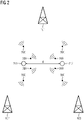
- At least two transponder antennas 211-212 at a distance d from one another transmit radio signals 300 alternately at predetermined time intervals for locating RTLS transponders by unsynchronized base stations 101-103.
- These radio signals 300 can in particular be TWR radio signals used to determine the distance between the two antennas 211-212 can be exchanged.
- the two transponder antennas 211-212 are assigned to different RTLS transponders.
- a possible application of this variant is locating vehicles with UWB radio keys in an outdoor area.
- a first transponder antenna 211 is integrated into the UWB radio key, while a second transponder antenna 212 is arranged on the vehicle.
- TWR two-way ranging
- a first transponder antenna 211 can be included in the RTLS transponder 203, which is arranged on the autonomous vehicle 403 shown in Figure 1, while a second transponder antenna 212 can be included in the part on the vehicle part 402 attached RTLS transponder 202 is included. According to the explanations below, both the position of the autonomous vehicle 403 and the position of the vehicle part 402 can be determined simultaneously.
- the RTLS transponders assigned to the two transponder antennas 211-212 determine the distance between themselves using two-way ranging (TWR) and transmit radio signals 300 containing determined distance values, which can be detected by the base stations 101-103.
- the base stations 101-103 determine on the basis of the radio signals 300 exchanged between the RTLS transponders during the determination of the distance and on the basis of the determined distance values in each case radio signal reception time differences.
- the time intervals at which the two transponder antennas 211-212 alternately transmit the radio signals 300 are specified by signal propagation times between the two transponders and by signal processing times within the respective RTLS transponder for carrying out two-way ranging (TWR).
- the two transponder antennas 211-212 are comprised of the same RTLS transponder.
- the distance d between the two transponder antennas 211-212 is known a priori, in particular the base stations 101-103, and the two transponder antennas 211-212 transmit the radio signals 300 alternately at time intervals known to the base stations 101-103. According to the explanations below, both the position of the respective RTLS transponder and its spatial alignment can be determined simultaneously.
- the base stations 101-103 determine on the basis of the radio signals 300 transmitted by the two transponder antennas 211-212 and on the basis of the distance d between the two transponder antennas 211-212 respectively radio signal reception time differences between the of the transponders -Antennas 211-212 received radio signals 300.
- the position of the or the respective RTLS transponder is then calculated using the radio signal reception time differences determined by the base stations 101-103.
- the position of the respective RTLS transponder is determined according to the time difference of arrival (TDOA). Only the two transponder antennas 211-212 send radio signals for locating, while the base stations 101-103 only receive the radio signals 300. Details on position determination using TDOA can be found in Wikipedia, for example described at Multilateration ( https://en.wikipedia.org/wiki/Multilateration ).
- a system of equations can be set up with which the positions of the two transponder antennas 211-212 are calculated.
- a calculation of two-dimensional coordinations X T1 , Y T1 and X T2 , Y T2 of the two transponder antennas 211-212 is described below. The following explanations can be extended in an analogous manner to a calculation of three-dimensional coordinates.
- c is the propagation speed of the radio signals 300 sent by the transponder antennas 211-212 .
- Ranging (TWR) can be determined.
- the equation system comprising three equations for the radio signal reception time differences ⁇ Bi determined by the base stations 101-103 and the equation for the distance d between the transponder antennas form an overall equation system of four equations for the four coordinations X T1 , Y T1 , X T2 , Y T2 of the two transponder antennas 211-212.
- This overall system of equations can be solved, for example, by means of an approximation solution through error minimization.
- the overall system of equations can also be solved analytically in analogy to the Kleusberg and Bancroft algorithms used in GPS localization.
Abstract
In einem Funkortungssystem wird eine Position zumindest eines Transponders mittels mehrerer Basisstationen (101-103) des Funkortungssystems ermittelt, wobei die Basisstationen jeweils an einer vorgegebenen Position angeordnet sind. Zumindest zwei einen Abstand (d) zueinander aufweisende Transponder-Antennen (211-212) senden in vorgegebenen Zeitabständen abwechselnd Funksignale (300). Die Basisstationen ermitteln auf Basis der von den beiden Transponder-Antennen gesendeten Funksignale und anhand des Abstands zwischen den beiden Transponder-Antennen jeweils Funksignal-Empfangszeitdifferenzen zwischen den von den Transponder-Antennen empfangenen Funksignalen. Die Position des zumindest einen Transponders wird anhand der Funksignal-Empfangszeitdifferenzen ermittelt.In a radio location system, a position of at least one transponder is determined using a plurality of base stations (101-103) of the radio location system, the base stations each being arranged at a predetermined position. At least two transponder antennas (211-212) at a distance (d) from one another transmit radio signals (300) alternately at predetermined time intervals. Based on the radio signals sent by the two transponder antennas and on the basis of the distance between the two transponder antennas, the base stations determine radio signal reception time differences between the radio signals received by the transponder antennas. The position of the at least one transponder is determined using the radio signal reception time differences.
Description
Die vorliegende Erfindung betrifft ein Verfahren zum Betrieb eines Funkortungssystems, insbesondere eines Real-time Locating System (RTLS), ein Funkortungssystem zur Durchführung des Verfahrens und eine Basisstation für ein Funkortungssystem.The present invention relates to a method for operating a radio location system, in particular a real-time locating system (RTLS), a radio location system for carrying out the method, and a base station for a radio location system.
Funkbasierte Ortungsvorrichtungen können beispielsweise auf RFID-Tags (radio-frequency identification) basieren, die zur Identifizierung oder Ortung von Gegenständen an diesen jeweils angebracht werden. RFID-Tags umfassen eine Speichereinheit, deren Inhalt mittels eines RFID-Lesegeräts ausgelesen, aber auch verändert werden kann. Üblicherweise ist in RFID-Tags jeweils zumindest ein Identifikator gespeichert. Zum Auslesen von in RFID-Tags gespeicherten Informationen senden RFID-Lesegeräte jeweils durch Erzeugung eines elektro-magnetischen Wechselfeldes ein Anfragesignal aus. Einerseits dient dieses elektro-magnetische Wechselfeld zur Energieversorgung insbesondere passiv betriebener RFID-Tags, die keine eigene Energiequelle aufweisen. Andererseits wird das elektro-magnetische Wechselfeld durch RFID-Tags zur Übermittlung eines Antwortsignals moduliert, beispielsweise durch Lastmodulation oder Variierung ihrer Antennenimpedanz.Radio-based locating devices can be based, for example, on RFID tags (radio-frequency identification), which are attached to objects in order to identify or locate them. RFID tags include a storage unit whose content can be read using an RFID reader, but can also be changed. At least one identifier is usually stored in each RFID tag. To read information stored in RFID tags, RFID readers send out a request signal by generating an alternating electromagnetic field. On the one hand, this electromagnetic alternating field is used to supply energy, in particular to passively operated RFID tags that do not have their own energy source. On the other hand, the alternating electromagnetic field is modulated by RFID tags to transmit a response signal, for example by load modulation or by varying their antenna impedance.
Funkortungssysteme für industrielle Automatisierungssysteme müssen besonderen Anforderungen hinsichtlich zuverlässiger Datenübermittlung, Authentizität übermittelter Daten und Unempfindlichkeit gegenüber Störquellen genügen. Da industrielle Automatisierungssysteme zur Überwachung, Steuerung und Regelung von technischen Prozessen dienen, insbesondere im Bereich Fertigungs-, Prozess- und Gebäudeautomatisierung, können gestörte, manipulierte oder fehlerhaft konfigurierte Funkortungssysteme zu schwerwiegenden Auswirkungen führen, im ungünstigsten Fall zu einem Stillstand eines Automatisierungssystems.Radio location systems for industrial automation systems must meet special requirements in terms of reliable data transmission, authenticity of transmitted data and insensitivity to sources of interference. Since industrial automation systems are used to monitor, control and regulate technical processes, especially in the field Manufacturing, process and building automation, disrupted, manipulated or incorrectly configured radio location systems can lead to serious effects, in the worst case to an automation system coming to a standstill.
Aus
In
Aus der älteren europäischen Patentanmeldung mit dem Anmeldeaktenzeichen
In auf Ultra-Breitband-Technik (UWB) basierenden Funkortungssystemen können insbesondere Angle of Arrival (AoA - Einfallsrichtung), Time Difference of Arrival (TDOA) und Two-way Ranging (TWR) als Verfahren zur Positionsbestimmung unabhängig voneinander verwendet werden. Diese Verfahren weisen unterschiedliche Anforderungen hinsichtlich verwendeter Hardware und räumlicher Anordnung der Hardware auf. TDOA ermöglicht eine Ortung einer Vielzahl von Transpondern gleichzeitig, erfordert hierfür jedoch zumindest 3 üblicherweise synchronisierte Basisstationen. Dagegen wird für TWR grundsätzlich nur eine Basisstation benötigt, um zumindest eine Distanz zu einem zu ortenden Transponder zu ermitteln. AoA erfordert zwar keine Synchronisierung der Basisstationen, jedoch eine genaue Ausrichtung der Basisstationen sowie mehrere Empfangsantennen pro Basisstationen. Nachteilig bei AoA ist eine mit zunehmender Entfernung abnehmende Genauigkeit.In particular, Angle of Arrival (AoA - direction of arrival), Time Difference of Arrival (TDOA) and Two-way Ranging (TWR) can be used independently as methods for position determination in radio location systems based on ultra-wideband technology (UWB). These methods have different requirements with regard to the hardware used and the spatial arrangement of the hardware. TDOA enables a large number of transponders to be located simultaneously, but requires at least 3 base stations, which are usually synchronized. On the other hand, only one base station is required for TWR in order to determine at least a distance to a transponder to be located. While AoA does not require base station synchronization, it does require precise base station alignment and multiple receiving antennas per base station. The disadvantage of AoA is that the accuracy decreases with increasing distance.
In vielen Ländern ist es regulatorisch unzulässig, dass Basisstationen von Funkortungssystemen in Außenbereichen insbesondere zur Zeitsynchronisation UWB-Signale senden. Aus diesem Grund werden Basisstationen entweder über drahtgebundene Verbindungen oder mittels separater Funkübertragungstechnologien, beispielsweise im 2,4 GHz ISM-Band, synchronisiert.In many countries, it is illegal for base stations of radio location systems to transmit UWB signals in outdoor areas, especially for time synchronization. For this reason, base stations are synchronized either via wired connections or using separate radio transmission technologies, for example in the 2.4 GHz ISM band.
Der vorliegenden Erfindung liegt daher die Aufgabe zugrunde, ein Verfahren zum Betrieb eines Funkortungssystems zu schaffen, das eine genaue Ortung einer Vielzahl von Transpondern ermöglicht und mit geringem Aufwand in Außenbereichen genutzt werden kann, sowie zur Durchführung des Verfahrens geeignete Mittel bzw. Realisierungen anzugeben.The present invention is therefore based on the object of creating a method for operating a radio location system that enables precise location of a large number of transponders and can be used outdoors with little effort, as well as specifying suitable means or implementations for carrying out the method.
Diese Aufgabe wird erfindungsgemäß durch ein Verfahren mit den in Anspruch 1 angegebenen Merkmalen, durch ein Funkortungssystem mit den in Anspruch 10 angegebenen Merkmalen und durch eine Basisstation mit den in Anspruch 11 angegebenen Merkmalen gelöst. Vorteilhafte Weiterbildungen der vorliegenden Erfindung sind in den abhängigen Ansprüchen angegeben.This object is achieved according to the invention by a method having the features specified in claim 1, by a radio location system having the features specified in claim 10 and by a base station having the features specified in claim 11. Advantageous developments of the present invention are specified in the dependent claims.
Entsprechend dem erfindungsgemäßen Verfahren zum Betrieb eines Funkortungssystems wird eine Position zumindest eines Transponders mittels mehrerer Basisstationen des Funkortungssystems ermittelt. Dabei sind die Basisstationen jeweils an einer vorgegebenen bzw. bekannten Position angeordnet. Vorzugsweise ist das Funkortungssystem ein zumindest RFID-basiertes, UWB-basiertes bzw. 2,4 GHz ISM-Band-basiertes Real-time Locating System.According to the method according to the invention for operating a radio location system, a position of at least one transponder is determined using a plurality of base stations of the radio location system. The base stations are each arranged at a predetermined or known position. The radio location system is preferably an at least RFID-based, UWB-based or 2.4 GHz ISM band-based real-time locating system.
Erfindungsgemäß senden zumindest zwei einen Abstand zueinander aufweisende Transponder-Antennen in vorgegebenen Zeitabständen abwechselnd Funksignale. Anhand der von den beiden Transponder-Antennen gesendeten Funksignale kann der Abstand zwischen den beiden Transponder-Antennen ermittelt werden, insbesondere entsprechend Two-way Ranging (TWR).According to the invention, at least two transponder antennas which are at a distance from one another transmit radio signals alternately at predetermined time intervals. The distance can be determined based on the radio signals sent by the two transponder antennas between the two transponder antennas can be determined, in particular according to two-way ranging (TWR).
Die Basisstationen ermitteln erfindungsgemäß auf Basis der von den beiden Transponder-Antennen gesendeten Funksignale und anhand des Abstands zwischen den beiden Transponder-Antennen jeweils Funksignal-Empfangszeitdifferenzen zwischen den von den Transponder-Antennen empfangenen Funksignalen. Anhand dieser Funksignal-Empfangszeitdifferenzen wird die Position des zumindest einen Transponders ermittelt, insbesondere entsprechend Time Difference of Arrival (TDOA). Dabei ist keine Synchronisierung der Basisstationen untereinander erforderlich, da sich mit den ermittelten Funksignal-Empfangszeitdifferenzen ein Gleichungssystem aufstellen lässt, anhand dessen die Positionen der beiden Transponder-Antennen berechnet werden können. Vorzugsweise senden somit nur die beiden Transponder-Antennen Funksignale, während die Basisstationen Funksignale lediglich empfangen.According to the invention, the base stations determine radio signal reception time differences between the radio signals received by the transponder antennas on the basis of the radio signals transmitted by the two transponder antennas and using the distance between the two transponder antennas. The position of the at least one transponder is determined on the basis of these radio signal reception time differences, in particular in accordance with the Time Difference of Arrival (TDOA). The base stations do not need to be synchronized with each other, since the determined radio signal reception time differences can be used to set up a system of equations, which can be used to calculate the positions of the two transponder antennas. Thus, preferably only the two transponder antennas transmit radio signals, while the base stations only receive radio signals.
Entsprechend einer ersten Ausführungsvariante der vorliegenden Erfindung ist eine erste Transponder-Antenne von einem ersten Transponder umfasst, während eine zweite Transponder-Antenne von einem zweiten Transponder umfasst ist. In diesem Fall sind die Zeitabstände, in denen die beiden Transponder-Antennen abwechselnd die Funksignale senden, durch Signallaufzeiten zwischen den beiden Transpondern sowie durch Signalverarbeitungszeiten innerhalb des jeweiligen Transponders vorgegeben. Insbesondere können die beiden Transponder untereinander eine Abstandsermittlung mittels Two-Way-Ranging durchführen und ermittelte Abstandswerte umfassende Funksignale senden. Vorteilhafterweise ermitteln die (unsynchronisierten) Basisstationen auf Basis während der Abstandsermittlung zwischen den Transpondern ausgetauschter Funksignale und anhand der ermittelten Abstandswerte jeweils die Funksignal-Empfangszeitdifferenzen.According to a first embodiment variant of the present invention, a first transponder antenna is comprised by a first transponder, while a second transponder antenna is comprised by a second transponder. In this case, the time intervals at which the two transponder antennas alternately transmit the radio signals are specified by signal propagation times between the two transponders and by signal processing times within the respective transponder. In particular, the two transponders can determine the distance from one another by means of two-way ranging and transmit radio signals containing the determined distance values. Advantageously, the (unsynchronized) base stations determine on the basis of radio signals exchanged between the transponders during the determination of the distance the radio signal reception time differences based on the determined distance values.
Eine mögliche Anwendung der ersten Ausführungsvariante ist beispielsweise eine Ortung von Fahrzeugen mit UWB-Funkschlüsseln in einem Außenbereich. Sobald ein UWB-Funkschlüssel mit einem Fahrzeug kommuniziert und dabei Funksignale entsprechend Two-way Ranging (TWR) mit diesem austauscht, können diese Funksignale durch unsynchronisierte Basisstationen im Außenbereich erfasst und zur Ermittlung der Positionen des UWB-Funkschlüssels und des Fahrzeugs ausgewertet werden.A possible application of the first variant is, for example, locating vehicles with UWB radio keys in an outdoor area. As soon as a UWB radio key communicates with a vehicle and exchanges radio signals with it in accordance with Two-way Ranging (TWR), these radio signals can be detected by unsynchronized base stations outside and evaluated to determine the positions of the UWB radio key and the vehicle.
Entsprechend einer zweiten Ausführungsvariante der vorliegenden Erfindung sind die beiden Transponder-Antennen von demselben Transponder umfasst und weisen einen den Basisstationen bekannten bzw. bekannt gemachten Abstand zueinander auf. In diesem Fall senden die beiden Transponder-Antennen die Funksignale abwechselnd in den Basisstationen bekannten bzw. bekannt gemachten Zeitabständen. Anhand der von den beiden Transponder-Antennen gesendeten Funksignale und mittels der (unsynchronisierten) Basisstationen kann somit eine Position des Transponders und seine räumliche Ausrichtung ermittelt werden.According to a second embodiment variant of the present invention, the two transponder antennas are comprised of the same transponder and are at a distance from one another that is known or made known to the base stations. In this case, the two transponder antennas transmit the radio signals alternately at time intervals that are known or made known to the base stations. A position of the transponder and its spatial alignment can thus be determined on the basis of the radio signals sent by the two transponder antennas and by means of the (unsynchronized) base stations.
Das erfindungsgemäße Funkortungssystem ist zur Durchführung eines Verfahrens entsprechend vorangehenden Ausführungen vorgesehen und umfasst mehrere jeweils an einer vorgegebenen Position angeordnete Basisstationen zur Ermittlung einer Position zumindest eines Transponders sowie zumindest zwei einen Abstand zueinander aufweisende Transponder-Antennen. Die Transponder-Antennen sind dazu ausgestaltet und eingerichtet, in vorgegebenen Zeitabständen abwechselnd Funksignale zu senden. Erfindungsgemäß sind die Basisstationen dazu ausgestaltet und eingerichtet, auf Basis der von den beiden Transponder-Antennen gesendeten Funksignale und anhand des Abstands zwischen den beiden Transponder-Antennen jeweils Funksignal-Empfangszeitdifferenzen zwischen den von den Transponder-Antennen empfangenen Funksignalen zu ermitteln, wobei die Position des zumindest einen Transponders anhand der Funksignal-Empfangszeitdifferenzen ermittelt wird.The radio location system according to the invention is provided for carrying out a method according to the preceding explanations and comprises a plurality of base stations, each arranged at a predetermined position, for determining a position of at least one transponder and at least two transponder antennas which are spaced apart from one another. The transponder antennas are designed and set up to transmit radio signals alternately at predetermined time intervals. According to the invention, the base stations are designed and set up for this purpose on the basis of the two transponder antennas transmitted radio signals and using the distance between the two transponder antennas to determine radio signal reception time differences between the radio signals received by the transponder antennas, the position of the at least one transponder being determined using the radio signal reception time differences.
Die erfindungsgemäße Basisstation für ein Funkortungssystem, ist dafür ausgestaltet und eingerichtet, zusammen mit weiteren Basisstationen eine Position eines Transponders zu ermitteln sowie von zumindest zwei einen Abstand zueinander aufweisende Transponder-Antennen in vorgegebenen Zeitabständen abwechselnd gesendete Funksignale zu empfangen. Außerdem ist die Basisstation dafür ausgestaltet und eingerichtet, auf Basis der von den beiden Transponder-Antennen gesendeten Funksignale und anhand des Abstands zwischen den beiden Transponder-Antennen jeweils Funksignal-Empfangszeitdifferenzen zwischen den von den Transponder-Antennen empfangenen Funksignalen zu ermitteln, wobei die Position des zumindest einen Transponders anhand der Funksignal-Empfangszeitdifferenzen zu ermittelt wird.The base station according to the invention for a radio location system is designed and set up to determine a position of a transponder together with other base stations and to receive radio signals transmitted alternately at predetermined time intervals by at least two transponder antennas that are spaced apart from one another. In addition, the base station is designed and set up to determine radio signal reception time differences between the radio signals received by the transponder antennas on the basis of the radio signals transmitted by the two transponder antennas and on the basis of the distance between the two transponder antennas, with the position of the at least one transponder is determined based on the radio signal reception time differences.
Die vorliegende Erfindung wird nachfolgend an einem Ausführungsbeispiel anhand der Zeichnung näher erläutert. Es zeigt
- Figur 1
- Funkortungssystem mit mehreren Basisstationen für ein industrielles Automatisierungssystem,
- Figur 2
- eine schematische Darstellung eines Austauschs von Funksignalen innerhalb des Funkortungssystems gemäß
Figur 1 zur Ortung von RTLS-Transpondern durch unsynchronisierte Basisstationen.
- figure 1
- Radio location system with multiple base stations for an industrial automation system,
- figure 2
- a schematic representation of an exchange of radio signals within the radio location system according to FIG
figure 1 for locating RTLS transponders using unsynchronized base stations.
Das in
Mittels eines ersten RTLS-Transponders 201 wird beispielsweise ein Stückgut 401 auf einem Transportband überwacht, dessen Antrieb 501 durch eine erste speicherprogrammierbare Steuerung 601 gesteuert wird. Ein zweiter RTLS-Transponder 202 ist im vorliegenden Ausführungsbeispiel an einem Fahrzeugteil 402 befestigt, das in einer Fahrzeugfertigungslinie durch einen Roboter 502 transportiert und montiert wird. Der Roboter wird durch eine zweite speicherprogrammierbare Steuerung 602 gesteuert, die ebenso wie die erste speicherprogrammierbare Steuerung 601 mit einer zentralen Überwachungs- und Steuerungseinheit 600 verbunden ist. Durch die Überwachungs- und Steuerungseinheit 600 werden u.a. die speicherprogrammierbaren Steuerungen 601, 602 und das Funkortungssystem projektiert bzw. überwacht.A
Das Funkortungssystem dient im vorliegenden Ausführungsbeispiel außerdem zur Überwachung der Position eines autonomen Fahrzeugs 403, mit denen Produktionsgüter zur Fahrzeugfertigungslinie transportiert werden. An dem autonomen Fahrzeug 403 ist zur Ortung ein dritter RTLS-Transponder 203 angeordnet. Neben UWB- bzw. 2,4 GHz ISM-Band-Komponenten kann das Funkortungssystem beispielsweise zusätzliche Komponenten zur GPS-, WLAN- oder Inertialsensorik-basierten Ortung umfassen. Dabei können mehrere oder alle dieser Komponenten in die RTLS-Transponder 201-203 und Basisstationen 101-105 des Funkortungssystems integriert sein.In the present exemplary embodiment, the radio location system is also used to monitor the position of an
Die Basisstationen 101-105 sind mit einer als Gateway 100 ausgestalteten Auswertevorrichtung des Funkortungssystems verbunden. Die RTLS-Transponder 201-203 übermitteln vorzugsweise jeweils einen dem jeweils zu ortenden Gegenstand zugeordneten Objektidentifikator an die Basisstationen 101-105. Auf dieser Basis senden die Basisstationen 101-105 Datagramme 301-305, die insbesondere erfasste Signallaufzeitinformationen, Signalempfangszeitinformationen, Informationen über Signalempfangszeitdifferenzen bzw. Signalstärkemesswerte von empfangenen Transpondersignalen bzw. Objektidentifikatoren umfassen, zur Auswertung an das Gateway 100.The base stations 101-105 are connected to an evaluation device, designed as a
Das Gateway 100 des Funkortungssystems übermittelt wiederum die erfassten Positionen der RTLS-Transponder 201-203 einschließlich der Objektidentifikatoren an die Überwachungs- und Steuerungseinheit 600. Dementsprechend ist das Überwachungs- und Steuerungseinheit 600 dafür konfiguriert, eine graphische Darstellung der übermittelten Positionen der RTLS-Transponder 201-203 aufzubereiten bzw. anhand der übermittelten Positionen der RTLS-Transponder 201-203 einschließlich der Objektidentifikatoren den RTLS-Transpondern 201-203 im Überwachungs- und Steuerungseinheit 600 jeweils zugeordnete Ortsinformationen zu validieren.The
Entsprechend der Darstellung in
Bei einer ersten Ausführungsvariante sind die beiden Transponder-Antennen 211-212 unterschiedlichen RTLS-Transpondern zugeordnet. Eine mögliche Anwendung dieser Ausführungsvariante ist eine Ortung von Fahrzeugen mit UWB-Funkschlüsseln in einem Außenbereich. Dabei ist eine erste Transponder-Antenne 211 in den UWB-Funkschlüssel integriert, während eine zweite Transponder-Antenne 212 fahrzeugseitig angeordnet ist. Wenn der UWB-Funkschlüssel mit dem Fahrzeug kommuniziert und Funksignale 300 entsprechend Two-way Ranging (TWR) mit dem Fahrzeug austauscht, können die Funksignale 300 durch unsynchronisierte Basisstationen 101-103 im Außenbereich erfasst und zur Ermittlung der Positionen des UWB-Funkschlüssels und des Fahrzeugs ausgewertet werden.In a first variant, the two transponder antennas 211-212 are assigned to different RTLS transponders. A possible application of this variant is locating vehicles with UWB radio keys in an outdoor area. A
Entsprechend einem anderen Anwendungsbeispiel für die erste Ausführungsvariante kann eine erste Transponder-Antenne 211 von dem RTLS-Transponder 203 umfasst sein, der an dem in Figur 1 dargestellten autonomen Fahrzeug 403 angeordnet ist, während eine zweite Transponder-Antenne 212 von dem an dem Fahrzeugteil 402 befestigten RTLS-Transponder 202 umfasst ist. Entsprechend nachstehenden Ausführungen kann sowohl die Position des autonomen Fahrzeugs 403 als auch die Position des Fahrzeugteils 402 gleichzeitig ermittelt werden.According to another application example for the first embodiment variant, a
Entsprechend der ersten Ausführungsvariante führen die den beiden Transponder-Antennen 211-212 zugeordneten RTLS-Transponder untereinander eine Abstandsermittlung mittels Two-Way-Ranging (TWR) durch und senden ermittelte Abstandswerte umfassende Funksignale 300, die durch die Basisstationen 101-103 erfasst werden können. Die Basisstationen 101-103 ermitteln auf Basis der während der Abstandsermittlung zwischen den RTLS-Transpondern ausgetauschten Funksignale 300 und anhand der ermittelten Abstandswerte jeweils Funksignal-Empfangszeitdifferenzen. Insbesondere sind die Zeitabstände, in denen die beiden Transponder-Antennen 211-212 abwechselnd die Funksignale 300 senden, durch Signallaufzeiten zwischen den beiden Transpondern sowie durch Signalverarbeitungszeiten innerhalb des jeweiligen RTLS-Transponders zur Durchführung von Two-way Ranging (TWR) vorgegeben.According to the first embodiment variant, the RTLS transponders assigned to the two transponder antennas 211-212 determine the distance between themselves using two-way ranging (TWR) and transmit
Bei einer zweiten Ausführungsvariante sind die beiden Transponder-Antennen 211-212 von demselben RTLS-Transponder umfasst. In diesem Fall ist der Abstand d zwischen den beiden Transponder-Antennen 211-212 a priori bekannt, insbesondere den Basisstationen 101-103, und die beiden Transponder-Antennen 211-212 senden die Funksignale 300 abwechselnd in den Basisstationen 101-103 bekannten Zeitabständen. Entsprechend nachstehenden Ausführungen kann damit sowohl die Position des jeweiligen RTLS-Transponders als auch seine räumliche Ausrichtung gleichzeitig ermittelt werden.In a second embodiment variant, the two transponder antennas 211-212 are comprised of the same RTLS transponder. In this case, the distance d between the two transponder antennas 211-212 is known a priori, in particular the base stations 101-103, and the two transponder antennas 211-212 transmit the radio signals 300 alternately at time intervals known to the base stations 101-103. According to the explanations below, both the position of the respective RTLS transponder and its spatial alignment can be determined simultaneously.
Allgemein, also beiden Ausführungsvariante, ermitteln die Basisstationen 101-103 auf Basis der von den beiden Transponder-Antennen 211-212 gesendeten Funksignale 300 und anhand des Abstands d zwischen den beiden Transponder-Antennen 211-212 jeweils Funksignal-Empfangszeitdifferenzen zwischen den von den Transponder-Antennen 211-212 empfangenen Funksignalen 300. Die Position des bzw. der jeweiligen RTLS-Transponder wird dann anhand der durch die Basisstationen 101-103 jeweils ermittelten Funksignal-Empfangszeitdifferenzen berechnet. Insbesondere wird die Position des bzw. der jeweiligen RTLS-Transponder entsprechend Time Difference of Arrival (TDOA) ermittelt wird. Zur Ortung senden nur die beiden Transponder-Antennen 211-212 Funksignale, während die Basisstationen 101-103 die Funksignale 300 lediglich empfangen. Details zur Positionsermittlung mittels TDOA sind beispielsweise in Wikipedia unter Multilateration (https://en.wikipedia.org/wiki/ Multilateration) beschrieben.In general, i.e. in both embodiment variants, the base stations 101-103 determine on the basis of the radio signals 300 transmitted by the two transponder antennas 211-212 and on the basis of the distance d between the two transponder antennas 211-212 respectively radio signal reception time differences between the of the transponders -Antennas 211-212 received radio signals 300. The position of the or the respective RTLS transponder is then calculated using the radio signal reception time differences determined by the base stations 101-103. In particular, the position of the respective RTLS transponder is determined according to the time difference of arrival (TDOA). Only the two transponder antennas 211-212 send radio signals for locating, while the base stations 101-103 only receive the radio signals 300. Details on position determination using TDOA can be found in Wikipedia, for example described at Multilateration ( https://en.wikipedia.org/wiki/Multilateration ).
Anhand der ermittelten Funksignal-Empfangszeitdifferenzen kann ein Gleichungssystem aufgestellt werden, mit dem die Positionen der beiden Transponder-Antennen 211-212 berechnet werden. Im Sinn einer vereinfachten Darstellung wird nachfolgend eine Berechnung zweidimensionaler Koordinationen XT1, YT1 bzw. XT2, YT2 der beiden Transponder-Antennen 211-212 beschrieben. Nachfolgende Ausführungen lassen sich in analoger Weise auf eine Berechnung dreidimensionaler Koordinaten erweitern.Based on the determined radio signal reception time differences, a system of equations can be set up with which the positions of the two transponder antennas 211-212 are calculated. In terms of a simplified representation, a calculation of two-dimensional coordinations X T1 , Y T1 and X T2 , Y T2 of the two transponder antennas 211-212 is described below. The following explanations can be extended in an analogous manner to a calculation of three-dimensional coordinates.
Für den mittels Two-way Ranging (TWR) ermittelbaren Abstand d zwischen den beiden Transponder-Antennen 211-212 gilt folgende Gleichung: ![]()
![]()
Ausgehend von bekannten zweidimensionalen Koordinaten XB1, YB1, XB2, YB2, XB3, YB3 der in ![]()
![]()
Das drei Gleichungen umfassende Gleichungssystem für die durch die Basisstationen 101-103 ermittelten Funksignal-Empfangszeitdifferenzen ΔBi und die Gleichung für den Abstand d zwischen den Transponder-Antennen bilden ein Gesamtgleichungssystem aus vier Gleichungen für die insgesamt vier Koordinationen XT1, YT1, XT2, YT2 der beiden Transponder-Antennen 211-212. Dieses Gesamtgleichungssystem kann beispielsweise mittels einer Näherungslösung durch Fehlerminimierung gelöst werden. Das Gesamtgleichungssystem kann auch analytisch gelöst in Analogie zu bei einer GPS-Ortung verwendeten Kleusberg- und Bancroft-Algorithmen.The equation system comprising three equations for the radio signal reception time differences Δ Bi determined by the base stations 101-103 and the equation for the distance d between the transponder antennas form an overall equation system of four equations for the four coordinations X T1 , Y T1 , X T2 , Y T2 of the two transponder antennas 211-212. This overall system of equations can be solved, for example, by means of an approximation solution through error minimization. The overall system of equations can also be solved analytically in analogy to the Kleusberg and Bancroft algorithms used in GPS localization.
Claims (11)
bei dem anhand der von den beiden Transponder-Antennen (211-212) gesendeten Funksignale (300) der Abstand (d) zwischen den beiden Transponder-Antennen insbesondere entsprechend Two-way Ranging ermittelt wird.Method according to claim 1,
in which the distance (d) between the two transponder antennas is determined, in particular in accordance with two-way ranging, on the basis of the radio signals (300) sent by the two transponder antennas (211-212).
bei dem die Position des zumindest einen Transponders (201-203) entsprechend Time Difference of Arrival ermittelt wird.Method according to one of claims 1 or 2,
in which the position of the at least one transponder (201-203) is determined according to the time difference of arrival.
bei dem eine erste Transponder-Antenne von einem ersten Transponder umfasst ist, bei dem eine zweite Transponder-Antenne von einem zweiten Transponder umfasst ist und bei dem die Zeitabstände, in denen die beiden Transponder-Antennen abwechselnd die Funksignale senden, durch Signallaufzeiten zwischen den beiden Transpondern sowie durch Signalverarbeitungszeiten innerhalb des jeweiligen Transponders vorgegeben sind.Method according to one of claims 1 to 3,
in which a first transponder antenna is encompassed by a first transponder, in which a second transponder antenna is encompassed by a second transponder and in which the time intervals at which the two transponder antennas alternately send the radio signals, are specified by signal propagation times between the two transponders and by signal processing times within the respective transponder.
bei dem die beiden Transponder untereinander eine Abstandsermittlung mittels Two-Way-Ranging durchführen und ermittelte Abstandswerte umfassende Funksignale senden und bei dem auf Basis während der Abstandsermittlung zwischen den Transpondern ausgetauschter Funksignale und anhand der ermittelten Abstandswerte jeweils die Funksignal-Empfangszeitdifferenzen ermittelt werden.Method according to claim 4,
in which the two transponders determine the distance from one another by means of two-way ranging and transmit radio signals comprising the distance values determined, and in which the radio signal reception time differences are determined on the basis of radio signals exchanged between the transponders during the determination of the distance and using the determined distance values.
bei dem die beiden Transponder-Antennen von demselben Transponder umfasst sind sowie einen den Basisstationen bekannten Abstand zueinander aufweisen und bei dem die beiden Transponder-Antennen die Funksignale abwechselnd in den Basisstationen bekannten Zeitabständen senden.Method according to one of claims 1 to 3,
in which the two transponder antennas are comprised of the same transponder and are at a distance from one another that is known to the base stations, and in which the two transponder antennas transmit the radio signals alternately at time intervals known to the base stations.
bei dem anhand der von den beiden Transponder-Antennen gesendeten Funksignale eine Position des Transponders und seine räumliche Ausrichtung ermittelt werden.Method according to claim 6,
in which a position of the transponder and its spatial alignment are determined on the basis of the radio signals sent by the two transponder antennas.
bei dem nur die beiden Transponder-Antennen Funksignale senden und die Basisstationen Funksignale lediglich empfangen.Method according to one of claims 1 to 7,
in which only the two transponder antennas transmit radio signals and the base stations only receive radio signals.
bei dem das Funkortungssystem ein zumindest RFID-basiertes, UWB-basiertes und/oder 2,4 GHz ISM-Band-basiertes Real-time Locating System ist.Method according to one of claims 1 to 8,
in which the radio location system is at least an RFID-based, UWB-based and/or 2.4 GHz ISM band-based real-time locating system.
Priority Applications (2)
| Application Number | Priority Date | Filing Date | Title |
|---|---|---|---|
| EP20204943.3A EP3992659A1 (en) | 2020-10-30 | 2020-10-30 | Method for operating a wireless location system, wireless location system and base station |
| PCT/EP2021/070390 WO2022089798A1 (en) | 2020-10-30 | 2021-07-21 | Method for operating a radio locating system, radio locating system, and base station |
Applications Claiming Priority (1)
| Application Number | Priority Date | Filing Date | Title |
|---|---|---|---|
| EP20204943.3A EP3992659A1 (en) | 2020-10-30 | 2020-10-30 | Method for operating a wireless location system, wireless location system and base station |
Publications (1)
| Publication Number | Publication Date |
|---|---|
| EP3992659A1 true EP3992659A1 (en) | 2022-05-04 |
Family
ID=73043064
Family Applications (1)
| Application Number | Title | Priority Date | Filing Date |
|---|---|---|---|
| EP20204943.3A Withdrawn EP3992659A1 (en) | 2020-10-30 | 2020-10-30 | Method for operating a wireless location system, wireless location system and base station |
Country Status (2)
| Country | Link |
|---|---|
| EP (1) | EP3992659A1 (en) |
| WO (1) | WO2022089798A1 (en) |
Cited By (1)
| Publication number | Priority date | Publication date | Assignee | Title |
|---|---|---|---|---|
| WO2022253520A1 (en) | 2021-05-31 | 2022-12-08 | Siemens Aktiengesellschaft | Method for locating a transponder for a radio location system, radio location system and base station |
Citations (4)
| Publication number | Priority date | Publication date | Assignee | Title |
|---|---|---|---|---|
| WO2008027619A2 (en) * | 2006-09-01 | 2008-03-06 | Intermec Ip Corp. | Rfid tag system with block coding, such as space-time block coding |
| DE102009008174A1 (en) | 2009-02-10 | 2010-08-19 | Siemens Aktiengesellschaft | Method and system for determining the distance, the speed and / or the direction of movement of an RFID transponder |
| WO2012148721A1 (en) * | 2011-04-26 | 2012-11-01 | Microchip Technology Incorporated | Radio frequency tag location system and method |
| EP3031039A1 (en) | 2013-08-09 | 2016-06-15 | Martec S.p.A. | System for tracking the position of persons or items in structures provided with rooms intended to receive persons or items, such as ships, buildings or offshore platforms |
-
2020
- 2020-10-30 EP EP20204943.3A patent/EP3992659A1/en not_active Withdrawn
-
2021
- 2021-07-21 WO PCT/EP2021/070390 patent/WO2022089798A1/en active Application Filing
Patent Citations (4)
| Publication number | Priority date | Publication date | Assignee | Title |
|---|---|---|---|---|
| WO2008027619A2 (en) * | 2006-09-01 | 2008-03-06 | Intermec Ip Corp. | Rfid tag system with block coding, such as space-time block coding |
| DE102009008174A1 (en) | 2009-02-10 | 2010-08-19 | Siemens Aktiengesellschaft | Method and system for determining the distance, the speed and / or the direction of movement of an RFID transponder |
| WO2012148721A1 (en) * | 2011-04-26 | 2012-11-01 | Microchip Technology Incorporated | Radio frequency tag location system and method |
| EP3031039A1 (en) | 2013-08-09 | 2016-06-15 | Martec S.p.A. | System for tracking the position of persons or items in structures provided with rooms intended to receive persons or items, such as ships, buildings or offshore platforms |
Non-Patent Citations (1)
| Title |
|---|
| JAFARI AHMADREZA: "New TDOA based localization method for HDR systems", 2 March 2015 (2015-03-02), pages 1 - 127, XP055794191, Retrieved from the Internet <URL:https://tel.archives-ouvertes.fr/tel-01192940v2/document> [retrieved on 20210412] * |
Cited By (1)
| Publication number | Priority date | Publication date | Assignee | Title |
|---|---|---|---|---|
| WO2022253520A1 (en) | 2021-05-31 | 2022-12-08 | Siemens Aktiengesellschaft | Method for locating a transponder for a radio location system, radio location system and base station |
Also Published As
| Publication number | Publication date |
|---|---|
| WO2022089798A1 (en) | 2022-05-05 |
Similar Documents
| Publication | Publication Date | Title |
|---|---|---|
| DE19824528C1 (en) | Transponder detection method e.g. for security tags, in region divided into at least two cells | |
| EP3219019B1 (en) | Antenna device, radiodetection system and method for emitting a radio signal | |
| EP3679531A1 (en) | Production system and production control method for controlling a production system | |
| DE102012212856B4 (en) | Method and read / write device for detecting, selecting and reporting at least one of a plurality of contactless readable transponders | |
| DE102020133784B3 (en) | Security system and a method using a security system | |
| WO2022002503A1 (en) | Method for operating a radio location system, base station, and evaluation device | |
| EP3992659A1 (en) | Method for operating a wireless location system, wireless location system and base station | |
| EP1836654B1 (en) | Method for locating a backscatterable transponder | |
| DE102006049862A1 (en) | Object position's information providing device for positioning e.g. passive high frequency-transponder, has position determining device computing information about object-position from relative phase positions of received signals | |
| DE102018117525B4 (en) | Method and device for position determination based on a UWB radio network | |
| EP1122684B1 (en) | Radio-identification system and method | |
| WO2022229240A1 (en) | Uwb localisation with independent uwb anchor synchronisation | |
| DE102018110150A1 (en) | INTERIOR LOCATION SYSTEM WITH ENERGY CONSUMPTION-CONTROLLED MOBILE TRANSMIT RECEIVERS | |
| EP3273381B1 (en) | Rfid device and method for communicating with at least one rfid transponder | |
| DE102005036088A1 (en) | Method for locating of object, especially a person, uses transmitting and receiving unit which is connected to two spaced apart antenna, wherein different individual identification signals are allocated to two antenna | |
| EP3414588A1 (en) | Device and method for determining the position of a transmitter in relation to a detection area | |
| EP4328612A1 (en) | Method for operating a radio positioning system, radio positioning system and transponder | |
| EP4123331A1 (en) | Wireless location system, base station, transponder and method for operating a wireless location system | |
| EP3015755A1 (en) | RFID element, RFID transmitter/reception system and safety switch | |
| EP4099043A1 (en) | Radio location system and base station and method for locating a transponder for a radio location system | |
| EP3798664A1 (en) | Object identification device and method for operating a radio-based and/or optical object identification device and object identification system | |
| EP1764623A1 (en) | Method and apparatus for distance determination between a RFID reader/writer and a mobile RFID data storage | |
| WO2022229239A1 (en) | Reliably locating a uwb mobile unit | |
| EP3910529A1 (en) | Method for local detection and tracking of rfid transponders using a reader device | |
| EP3916419A1 (en) | Method for operating a wireless location system and base station |
Legal Events
| Date | Code | Title | Description |
|---|---|---|---|
| PUAI | Public reference made under article 153(3) epc to a published international application that has entered the european phase |
Free format text: ORIGINAL CODE: 0009012 |
|
| STAA | Information on the status of an ep patent application or granted ep patent |
Free format text: STATUS: THE APPLICATION HAS BEEN PUBLISHED |
|
| AK | Designated contracting states |
Kind code of ref document: A1 Designated state(s): AL AT BE BG CH CY CZ DE DK EE ES FI FR GB GR HR HU IE IS IT LI LT LU LV MC MK MT NL NO PL PT RO RS SE SI SK SM TR |
|
| STAA | Information on the status of an ep patent application or granted ep patent |
Free format text: STATUS: THE APPLICATION IS DEEMED TO BE WITHDRAWN |
|
| 18D | Application deemed to be withdrawn |
Effective date: 20221105 |