EP3983897B1 - Method for ensuring and maintaining the function of a complete safety-critical system - Google Patents
Method for ensuring and maintaining the function of a complete safety-critical system Download PDFInfo
- Publication number
- EP3983897B1 EP3983897B1 EP20743960.5A EP20743960A EP3983897B1 EP 3983897 B1 EP3983897 B1 EP 3983897B1 EP 20743960 A EP20743960 A EP 20743960A EP 3983897 B1 EP3983897 B1 EP 3983897B1
- Authority
- EP
- European Patent Office
- Prior art keywords
- functionalities
- sub
- graphs
- event
- availability
- Prior art date
- Legal status (The legal status is an assumption and is not a legal conclusion. Google has not performed a legal analysis and makes no representation as to the accuracy of the status listed.)
- Active
Links
- 238000000034 method Methods 0.000 title claims description 32
- 238000005192 partition Methods 0.000 claims description 44
- 238000012545 processing Methods 0.000 claims description 33
- 238000004891 communication Methods 0.000 claims description 23
- 238000012544 monitoring process Methods 0.000 claims description 15
- 238000012360 testing method Methods 0.000 claims description 12
- 238000004458 analytical method Methods 0.000 claims description 11
- 230000001419 dependent effect Effects 0.000 claims description 7
- 238000004590 computer program Methods 0.000 claims description 6
- 230000006870 function Effects 0.000 description 33
- 238000007726 management method Methods 0.000 description 15
- 238000013461 design Methods 0.000 description 6
- 230000018109 developmental process Effects 0.000 description 6
- 238000001514 detection method Methods 0.000 description 5
- 238000009826 distribution Methods 0.000 description 5
- 230000015654 memory Effects 0.000 description 5
- 230000008569 process Effects 0.000 description 5
- 230000033772 system development Effects 0.000 description 5
- 238000011161 development Methods 0.000 description 4
- 230000005764 inhibitory process Effects 0.000 description 4
- 238000000354 decomposition reaction Methods 0.000 description 3
- 230000000694 effects Effects 0.000 description 3
- 230000008901 benefit Effects 0.000 description 2
- 238000004364 calculation method Methods 0.000 description 2
- 230000008859 change Effects 0.000 description 2
- 201000006618 congenital myasthenic syndrome 6 Diseases 0.000 description 2
- 230000002950 deficient Effects 0.000 description 2
- 238000003745 diagnosis Methods 0.000 description 2
- 238000002171 field ion microscopy Methods 0.000 description 2
- 238000001914 filtration Methods 0.000 description 2
- 238000012059 flow imaging microscopy Methods 0.000 description 2
- 230000007246 mechanism Effects 0.000 description 2
- 238000003860 storage Methods 0.000 description 2
- OKTJSMMVPCPJKN-UHFFFAOYSA-N Carbon Chemical compound [C] OKTJSMMVPCPJKN-UHFFFAOYSA-N 0.000 description 1
- 238000013459 approach Methods 0.000 description 1
- 230000002146 bilateral effect Effects 0.000 description 1
- 230000005540 biological transmission Effects 0.000 description 1
- 230000000903 blocking effect Effects 0.000 description 1
- 238000004422 calculation algorithm Methods 0.000 description 1
- 230000015556 catabolic process Effects 0.000 description 1
- 230000001364 causal effect Effects 0.000 description 1
- 238000006243 chemical reaction Methods 0.000 description 1
- 238000012937 correction Methods 0.000 description 1
- 238000013500 data storage Methods 0.000 description 1
- 238000006731 degradation reaction Methods 0.000 description 1
- 230000001934 delay Effects 0.000 description 1
- 230000007613 environmental effect Effects 0.000 description 1
- 238000002124 flame ionisation detection Methods 0.000 description 1
- 230000003993 interaction Effects 0.000 description 1
- 230000007257 malfunction Effects 0.000 description 1
- 238000004519 manufacturing process Methods 0.000 description 1
- 230000002085 persistent effect Effects 0.000 description 1
- 230000000644 propagated effect Effects 0.000 description 1
- GOLXNESZZPUPJE-UHFFFAOYSA-N spiromesifen Chemical compound CC1=CC(C)=CC(C)=C1C(C(O1)=O)=C(OC(=O)CC(C)(C)C)C11CCCC1 GOLXNESZZPUPJE-UHFFFAOYSA-N 0.000 description 1
- 238000012546 transfer Methods 0.000 description 1
- 230000000007 visual effect Effects 0.000 description 1
Images


Classifications
-
- G—PHYSICS
- G06—COMPUTING; CALCULATING OR COUNTING
- G06F—ELECTRIC DIGITAL DATA PROCESSING
- G06F11/00—Error detection; Error correction; Monitoring
- G06F11/07—Responding to the occurrence of a fault, e.g. fault tolerance
- G06F11/0703—Error or fault processing not based on redundancy, i.e. by taking additional measures to deal with the error or fault not making use of redundancy in operation, in hardware, or in data representation
- G06F11/0706—Error or fault processing not based on redundancy, i.e. by taking additional measures to deal with the error or fault not making use of redundancy in operation, in hardware, or in data representation the processing taking place on a specific hardware platform or in a specific software environment
- G06F11/0736—Error or fault processing not based on redundancy, i.e. by taking additional measures to deal with the error or fault not making use of redundancy in operation, in hardware, or in data representation the processing taking place on a specific hardware platform or in a specific software environment in functional embedded systems, i.e. in a data processing system designed as a combination of hardware and software dedicated to performing a certain function
- G06F11/0739—Error or fault processing not based on redundancy, i.e. by taking additional measures to deal with the error or fault not making use of redundancy in operation, in hardware, or in data representation the processing taking place on a specific hardware platform or in a specific software environment in functional embedded systems, i.e. in a data processing system designed as a combination of hardware and software dedicated to performing a certain function in a data processing system embedded in automotive or aircraft systems
-
- G—PHYSICS
- G06—COMPUTING; CALCULATING OR COUNTING
- G06F—ELECTRIC DIGITAL DATA PROCESSING
- G06F11/00—Error detection; Error correction; Monitoring
- G06F11/07—Responding to the occurrence of a fault, e.g. fault tolerance
- G06F11/0703—Error or fault processing not based on redundancy, i.e. by taking additional measures to deal with the error or fault not making use of redundancy in operation, in hardware, or in data representation
- G06F11/079—Root cause analysis, i.e. error or fault diagnosis
-
- G—PHYSICS
- G06—COMPUTING; CALCULATING OR COUNTING
- G06F—ELECTRIC DIGITAL DATA PROCESSING
- G06F11/00—Error detection; Error correction; Monitoring
- G06F11/30—Monitoring
- G06F11/3003—Monitoring arrangements specially adapted to the computing system or computing system component being monitored
- G06F11/3013—Monitoring arrangements specially adapted to the computing system or computing system component being monitored where the computing system is an embedded system, i.e. a combination of hardware and software dedicated to perform a certain function in mobile devices, printers, automotive or aircraft systems
-
- G—PHYSICS
- G06—COMPUTING; CALCULATING OR COUNTING
- G06F—ELECTRIC DIGITAL DATA PROCESSING
- G06F11/00—Error detection; Error correction; Monitoring
- G06F11/30—Monitoring
- G06F11/3055—Monitoring arrangements for monitoring the status of the computing system or of the computing system component, e.g. monitoring if the computing system is on, off, available, not available
Definitions
- the present invention relates to a method for ensuring and/or maintaining the function of a complex safety-critical overall system, an overall system which ensures and/or maintains its respective function in particular using a method according to the invention, and a computer program with program code for carrying out the method according to the invention.
- Modern means of transport such as motor vehicles or motorcycles are increasingly being equipped with driver assistance systems that use sensor systems to record the environment, recognize traffic situations and support the driver, e.g. by braking or steering or by issuing a visual or acoustic warning.
- Radar sensors, lidar sensors, camera sensors or the like are regularly used as sensor systems for detecting the environment.
- Conclusions about the environment can then be drawn from the sensor data determined by the sensors, which can be used, for example, to classify objects and/or the environment or to create an environment model.
- environmental detection is almost indispensable in the field of (partially) autonomous driving, so there is particular interest in the further development and advancement of the corresponding systems.
- curve detection based on object detection is of great importance, especially in the field of (partially) autonomous driving, since autonomous planning of trajectories along the route is difficult to implement without such curve detection.
- ISO 26262 (Road vehicles - Functional safety) for safety-relevant electronic/electrical (E/E) systems in motor vehicles defines the process model together with the required activities and work products as well as the methods to be used in their development and production.
- the implementation of ISO 26262 is intended to ensure the functional safety of a system with E/E components in the motor vehicle.
- the development processes at the software level are treated based on nested V-models and the required procedures and work results are defined.
- the implementation of functional safety in the software should be based on a specification of the software safety requirements. Ideally, the specification of the software safety requirements is closely aligned in terms of its internal structure to the software to be used or the desired software architecture.
- AUTOSAR AUTomotive Open System ARchitecture
- ECU Electronic Control Unit
- FIM Function Inhibition Manager
- the Function Inhibition Manager is the component responsible for system availability management.
- the output information of the Function Inhibition Manager is the logical availabilities calculated from the event status for the respective sub-functionalities into which an overall system must be appropriately decomposed.
- AUTOSAR also specifies the operation of FIMs in a pure client-server architecture supported by the runtime environment (RTE).
- the FIM takes on the role of a central server where the monitoring results of the monitors converge and from which the calculated availability of the sub-functionalities is distributed to the receivers.
- these signals sometimes travel arduous paths that can be the source of unacceptable delays and even transmission failures. In the latter case, the signal sender or receiver is/are completely cut off from the server and deprived of its "decision maker". deprived.
- Comparison here means that, in the simplest case, one instance takes into account the results of another instance and, in the somewhat more complex case, two or more instances carry out partial calculations and combine their partial results to form a common final result.
- a real availability determination distributed over a maximum of two instances can be realized by connecting the subfunctionality graphs of the different instances via common nodes.
- the availability of these common nodes also called distributed subfunctionalities, is calculated proportionally in two different instances and coordinated with each other via the communication path.
- the local availabilities in each instance can be determined without delay based on the monitoring results of the local monitors and the other instance can be notified of possible unavailability via the existing communication channel.
- Both instances should then automatically adjust the availability of their own subfunctionalities in the dependent subgraph. If communication fails, however, these instances continue to function without mutual comparison.
- the disadvantage here is that subfunctionalities can only be distributed over two instances and their comparison takes place asymmetrically.
- US 2011/153535 A1 a generic method for dividing a system into hierarchical subsystems and for event propagation for monitoring functions.
- the object of the present invention is to provide a generic method and system by which the disadvantages of the prior art can be overcome in a cost-effective manner.
- the event when an event occurs in the overall system, the event (or events) is first analyzed and those sub-functionalities that are affected by the event that has occurred are determined.
- the overall system is divided into interdependent sub-functionalities based on the findings of the event analysis, with a logical availability statement about the respective sub-functionalities being created or made using a function identifier based on the event diagnosis.
- the logical availability statement can be divided into "available” or "not available”.
- no other definable or selectable modes can be supported (there is therefore no selection system).
- the sub-functionalities form graphs.
- the present invention represents a cost-effective and efficient method for the availability management of individual components and component networks for safety-critical applications in motor vehicles in order to guarantee their functional safety and maximum possible availability.
- the graphs of the subfunctionalities can be coordinated if communication between them is available.
- the respective distributed subfunctionalities are implemented in two stages, whereby first local availability of the subfunctionalities of the graphs is determined and then exchanged with subfunctionalities of other graphs system-wide.
- the non-distributed subfunctionalities can also be implemented in a practical way in one stage.
- each monitor or event status can be automatically set to a status that indicates that it is not available as soon as it is deactivated by the function identifier (FID).
- FID function identifier
- the status of a monitor can be set to "NOTTESTED” as soon as it is deactivated by the function identifier, i.e. the internal event status "NOTTESTED” is automatically set for deactivated and correspondingly configured monitors.
- a software configuration and/or the relevant test cases are generated automatically from the requirements of the overall system.
- the configuration or application of the overall system as well as a diverse test case generation can thus be carried out automatically from the respective requirements.
- the need for manual programming for the purpose of application at the software level is eliminated.
- the development effort is reduced to the creation of the requirements at the software level.
- the entire system can be divided into different partitions.
- the partitions can contain a performance processing partition (PPP) for Processing, a safety processing partition (SPP) and an electrical power supply (EPS), in particular for safety monitoring, as well as an Ethernet partition (EP) for communication.
- PPP performance processing partition
- SPP safety processing partition
- EPS electrical power supply
- EP Ethernet partition
- processing partition PPP
- safety processing partition SPP
- EPS electrical power supply
- PPP processing partition
- SPP safety processing partition
- EPS electrical power supply
- the present invention also claims an overall system of a vehicle control system, in particular comprising a control unit (Electronic Control Unit ECU or Electronic Control Module ECM) or an ADCU or AuDCU (Assisted and Automated Driving Control Unit), which preferably uses a method according to the invention to ensure or maintain the function.
- a control unit Electronic Control Unit ECU or Electronic Control Module ECM
- ADCU or AuDCU Assisted and Automated Driving Control Unit
- the overall system is divided into interdependent sub-functionalities based on the event analysis, with the sub-functionalities forming graphs.
- a function identifier is provided which is designed to make a logical availability statement "available" or "not available” based on the event analysis.
- the graphs of the subfunctionalities within a functional unit will be processed jointly by connecting the graphs based on common subfunctionalities whose availability is calculated in a distributed manner, whereby distributed subfunctionalities are implemented in two stages, whereby first local availabilities of the subfunctionalities of the graphs are determined and then exchanged with subfunctionalities of other graphs system-wide.
- the method can also be designed as a computer-implemented method that describes a process plan or a procedure that is implemented or carried out using a computer.
- the computer such as a computer, a computer network or another programmable device known from the prior art, can process data using programmable calculation rules.
- essential properties can be achieved, for example, by a new program, new programs, an algorithm or the like.
- the present invention further claims a computer program with program code for carrying out a method according to the invention when the computer program is executed in a computer.
- the computer program can be stored on a computer-readable storage medium.
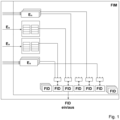
- Fig.1 is a design of a generic Function Inhibition Manager (FIM) according to the state of the art, where the input information of the FIM represents the monitoring results of the monitors (event status of the observed events E n ) which it receives from an Event Diagnostic Manager or Diagnostic Event Manager DEM (in Fig.1 not shown).
- the output information is the logical availability calculated from the event status (at least FAILED, but also TESTED, NOTTESTED, etc.) for the respective sub-functionalities (identifiable via a function identifier or Function Identifier FID), into which an overall system must be decomposed in a suitable manner.
- the respective FID can be activated ("on”) or deactivated ("off”) as an output.
- the present invention combines the advantages of the AUTOSAR specification in general, but in particular the FIM specification, with a distributed, multi-event capable and graph-based approach.
- the flat subfunctionality structure of AUTOSAR is ignored here.
- the subfunctionalities are made dependent on each other according to their physical dependencies in the real system. This creates a graph (ie an ordered set of nodes and directed edges), whose nodes represent the events and subfunctionalities.
- the respective events E1-E6, such as errors, malfunctions or the like, are also the input information from the event diagnostic manager DEM (Diagnostic Event Manager).
- DEM Diagnostic Event Manager
- the AUTOSAR interfaces remain unchanged, as a proxy function is provided to enable use in safety-relevant systems.
- the monitors are not treated any differently than other sub-functionalities: their execution is controlled by their own function identifiers, which are built into the dependency graph. This automatically eliminates the need for subsequent filtering of the monitoring results as part of a uniform concept.
- the last event status determined for a monitor that is subsequently deactivated via its function identifiers usually loses its significance, since, for example, there is no current result if the associated monitor is inactive.
- An exception to this rule are the so-called power-on monitors, which are by definition executed once and whose result is used for the entire cycle. It is therefore advisable to configure each monitor to determine whether the status of its event is automatically set to "NOTTESTED" as soon as it is deactivated via the function identifier.
- the "NOTTESTED" status then has a configuration-based effect on the dependent part of the graph.
- Such a graph can be described with syntactically identical rules, e.g. with: "Forbid B if A is ⁇ not ⁇ in ⁇ status>", where B is a sub-functionality, the logical negation is ⁇ not ⁇ optional and A can be a sub-functionality with the status ⁇ available, not available> or an event with the status ⁇ FAILED, TESTED, NOTTESTED, PASSED, NOTPASSED, ⁇ ... ⁇ >.
- This set of rules represents the requirements of system development at the software level for software development in the sense of ISO 26262.
- the corresponding configuration for the software and the relevant test cases for the automated module test can be generated automatically in a simple manner, with the configuration code generator and the test case generator or the test case generators being implemented in a diverse manner. Manual programming for the purpose of application at the software level is therefore no longer necessary.
- subfunctionality graphs where the simplest representation (logically “available” or “not available”) is used for the subfunctionalities, is particularly advantageous when tracing the events that led to a given (non-)availability picture.
- subfunctionality graphs are also particularly advantageous for the implementation of distributed systems.
- Distributed systems are systems in which selected subfunctionalities are partially calculated in different subfunctionality graphs at various locations (various ECUs, processors, cores (processor cores), integrity levels, asynchronous tasks) and for this reason a merging of the partial results is necessary.
- a distributed subfunctionality can only be considered available system-wide if all partial results are "available”.
- the AND operator is therefore used in particular to merge the partial results, as in Fig. 3 shown as an example.
- Fig.4 shows an advantageous design of the distribution concept when an event E occurs.
- the processor P1 is responsible for calculating the graph G1, which represents the dependency graph for a function identifier FID. This also applies to the processor P2 and the graph G2, which is also a dependency graph for a function identifier FID.
- the event E must now necessarily lead to the shutdown of a safety-critical component and can therefore automatically switch to the redundant shutdown path A2 if the local shutdown path A1 is defective (as shown by the cross in Fig.4 This is done by connecting the two function identifiers FID using the operator AND.
- all relevant aspects of the subfunctionality distribution can be set via configuration, such as: the two-stage nature of the distributed FIDs, the setting up of the necessary communication paths, the setting up of the data packets including data contents, the ensuring of freedom from communication errors (end-to-end protection with optional error correction) and the monitoring of freedom from communication errors.
- This configuration is derived from the system development requirements at the software level and automatically made available via a code generator, similar to the generation the test cases for the distribution aspects.
- a code generator similar to the generation the test cases for the distribution aspects.
- the graphs can be distributed to various processors and control units (electronic control units or ECUs), which are implemented either with or without an AUTOSAR stack (heterogeneous systems) in order to ensure that they work together in normal cases and that they operate independently in non-normal cases.
- ECUs electronic control units or ECUs
- the safety concept of an AuDCU (Automated Driving Control Unit) as described in Fig.6 shown as an example.
- the AuDCU represents an intrinsically safe computing platform for automated driving functions. This entails high requirements for its integrity level (e.g. ASIL-D) and availability.
- ASIL-D integrity level
- two further partitions were added to a performance processing partition or performance processing partition PPP, which generally provides very high computing capacities: the safety processing partition or safety processing partition SPP and the electrical power supply or electric power supply EPS.
- the electrical power supply EPS, safety processing partition SPP and performance processing partition PPP contain programmable processors and various availability managers AvM (Availability Manager). High-performance communication with the outside world is handled by a particularly non-programmable Ethernet partition EP.
- the safety processing partition SPP and electrical power supply EPS are primarily responsible for system security. They monitor all relevant supply voltages, temperatures and the like.
- the electrical power supply EPS, the safety processing partition SPP and the performance processing partition PPP also monitor their own processor resources including their program execution and can also monitor each other for correct functioning.
- the Ethernet partition EP also has built-in self-tests. When a partition-local event is detected, all partitions (if still functioning) are coordinated and brought into a predefined state with a specified maximum delay. This function must be guaranteed even if any number of events occur simultaneously (or at short intervals from one another) at any location in the AuDCU and regardless of their severity (up to the total failure of the partitions or the communication between them).
- the distributed availability management instances cannot operate independently of each other as long as the executing processors and the communication between them are intact. This is particularly the case because an availability change in one of the instances usually results in availability changes in the other instances (for example, if the electrical power supply EPS of the performance processing partition PPP is switched off via a shutdown path - as a dotted arrow in Fig.6 shown - the power supply is removed, the safety processing partition SPP must immediately stop monitoring the performance processing partition PPP in order to avoid detecting a series of non-existent errors).
- the instance that specifies an availability change does not necessarily have the ability to implement it (example: the safety processing partition SPP specifies a shutdown of the performance processing partition PPP power supply, but does not have the corresponding hardware connection, so the electrical power supply EPS must take over the implementation).
- This transfer of availability information in Fig.6 represented by dashed arrows, is realized with the help of distributed subfunctionalities.
- the communication between the availability management instances is monitored.
- the event that "communication has been interrupted” leads to a predefined reaction in each instance that suddenly becomes local.
- the communication paths between the availability management instances can also be used to exchange data to and from the event analysis or the event diagnosis manager DEM.
- the functionality described is automatically distributed to the three processors from a common set of requirements using code generators, both as a configuration and as a module test.
- the solution according to the invention is also suitable for cost-effective implementation of distributed availability management in many conceivable situations in which system boundaries must be overcome.
- Overcoming the boundaries between processors or microcontrollers ⁇ C as well as different integrity levels within a processor and other situations is particularly simplified, as exemplified in Fig.7 shown, e.g. design, boundaries between different in-house and/or 3rd party functions, boundaries between asynchronous tasks, boundaries between different integrity levels, boundaries between different processor cores C1, C2, boundaries between different processors and boundaries between different ECUs.
Landscapes
- Engineering & Computer Science (AREA)
- Theoretical Computer Science (AREA)
- Physics & Mathematics (AREA)
- Quality & Reliability (AREA)
- General Engineering & Computer Science (AREA)
- General Physics & Mathematics (AREA)
- Computing Systems (AREA)
- Mathematical Physics (AREA)
- Health & Medical Sciences (AREA)
- Biomedical Technology (AREA)
- Debugging And Monitoring (AREA)
- Hardware Redundancy (AREA)
Description
Die vorliegende Erfindung betrifft ein Verfahren zum Sicherstellen und/oder Aufrechterhalten der Funktion eines komplexen sicherheitskritischen Gesamtsystems, ein Gesamtsystem, welches seine jeweilige Funktion insbesondere anhand eines erfindungsgemäßen Verfahrens sicherstellt und/oder aufrechterhält sowie ein Computerprogramm mit Programmcode zur Durchführung des erfindungsgemäßen Verfahrens.The present invention relates to a method for ensuring and/or maintaining the function of a complex safety-critical overall system, an overall system which ensures and/or maintains its respective function in particular using a method according to the invention, and a computer program with program code for carrying out the method according to the invention.
Moderne Fortbewegungsmittel wie Kraftfahrzeuge oder Motorräder werden zunehmend mit Fahrerassistenzsystemen ausgerüstet, welche mit Hilfe von Sensorsystemen die Umgebung erfassen, Verkehrssituationen erkennen und den Fahrer unterstützen, z. B. durch einen Brems- oder Lenkeingriff oder durch die Ausgabe einer optischen oder akustischen Warnung. Als Sensorsysteme zur Umgebungserfassung werden regelmäßig Radarsensoren, Lidarsensoren, Kamerasensoren oder dergleichen eingesetzt. Aus den durch die Sensoren ermittelten Sensordaten können anschließend Rückschlüsse auf die Umgebung gezogen werden, womit z. B. eine Objekt- und/oder Umgebungsklassifizierung bzw. ein Umfeldmodell erstellt werden kann. Ferner ist die Umgebungserfassung nahezu unverzichtbar im Bereich des (teil-) autonomen Fahrens, sodass ein besonderes Interesse an der Fort- und Weiterentwicklung der entsprechenden Systeme besteht. Ferner ist gerade im Bereich des (teil-) autonomen Fahrens die Kurvenerkennung anhand von Objektdetektionen von großer Bedeutung, da eine autonome Planung von Trajektorien entlang der Streckenführung ohne eine derartige Kurvenerkennung nur schwer umsetzbar ist.Modern means of transport such as motor vehicles or motorcycles are increasingly being equipped with driver assistance systems that use sensor systems to record the environment, recognize traffic situations and support the driver, e.g. by braking or steering or by issuing a visual or acoustic warning. Radar sensors, lidar sensors, camera sensors or the like are regularly used as sensor systems for detecting the environment. Conclusions about the environment can then be drawn from the sensor data determined by the sensors, which can be used, for example, to classify objects and/or the environment or to create an environment model. Furthermore, environmental detection is almost indispensable in the field of (partially) autonomous driving, so there is particular interest in the further development and advancement of the corresponding systems. Furthermore, curve detection based on object detection is of great importance, especially in the field of (partially) autonomous driving, since autonomous planning of trajectories along the route is difficult to implement without such curve detection.
Aufgrund von aktuellen Automatisierungstrends bei der Automobilindustrie insbesondere im Bereich derartiger Assistenzsysteme bis hin zum autonomen Fahren lassen die Komplexität elektronischer und elektrischer Komponenten sowie die Anforderungen an deren Verfügbarkeit und funktionaler Sicherheit rapide anwachsen. Dabei ist die fehlerfreie Funktion der Komponenten im Einzelnen und die fehlerfreie Zusammenarbeit dieser Komponenten ausschlaggebend für einen fehlerfreien Verkehrsbetrieb. Bei der Zusammenarbeit von unterschiedlichen Komponenten und Funktionalitäten und Subfunktionalitäten ist insbesondere die Hard- und Softwarearchitektur von besonderer Bedeutung.Due to current automation trends in the automotive industry, particularly in the area of assistance systems such as autonomous driving, the complexity of electronic and electrical components and the requirements for their availability and functional safety are growing rapidly. The error-free function of the individual components and the error-free cooperation of these components is crucial for error-free traffic operations. When different components and functionalities and sub-functionalities work together, the hardware and software architecture is particularly important.
Die ISO 26262 ("Road vehicles - Functional safety") für sicherheitsrelevante elektronische/elektrische (E/E) Systeme in Kraftfahrzeugen definiert das Vorgehensmodell zusammen mit den geforderten Aktivitäten und Arbeitsprodukten sowie die anzuwendenden Methoden in derer Entwicklung und Produktion. Die Umsetzung der ISO 26262 soll die funktionale Sicherheit eines Systems mit E/E Komponenten im Kraftfahrzeug gewährleisten. Dabei werden die Entwicklungsprozesse auf Softwareebene in Anlehnung an geschachtelte V-Modelle behandelt und die erforderlichen Vorgehensweisen und Arbeitsergebnisse definiert. Beispielsweise soll die Implementierung der funktionalen Sicherheit in der Software auf Basis einer Spezifikation der Software-Sicherheitsanforderungen erfolgen. Idealerweise ist die Spezifikation der Software-Sicherheitsanforderungen von ihrer internen Struktur her an die zu verwendende Software bzw. die angestrebte Softwarearchitektur eng ausgerichtet.ISO 26262 ("Road vehicles - Functional safety") for safety-relevant electronic/electrical (E/E) systems in motor vehicles defines the process model together with the required activities and work products as well as the methods to be used in their development and production. The implementation of ISO 26262 is intended to ensure the functional safety of a system with E/E components in the motor vehicle. The development processes at the software level are treated based on nested V-models and the required procedures and work results are defined. For example, the implementation of functional safety in the software should be based on a specification of the software safety requirements. Ideally, the specification of the software safety requirements is closely aligned in terms of its internal structure to the software to be used or the desired software architecture.
Insbesondere wird hierzu die sogenannte AUTOSAR (AUTomotive Open System ARchitecture) Architektur eingesetzt. Es handelt sich hierbei um eine offene und standardisierte Softwarearchitektur für elektronische Steuergeräte (sogenannte Electronic Control Units; kurz ECU). Gemäß AUTOSAR Architektur berichten verschiedene Monitore ihre Überwachungsergebnisse (Ereignisstatus) an einen Ereignisdiagnosemanager bzw. Diagnostic Event Manager (DEM), welcher diese dann an einen sogenannten Funktionssperrmanager bzw. Function Inhibition Manager (FIM) weiterleitet. Der Funktionssperrmanager ist in der AUTOSAR Architektur die Komponente, die für das Systemverfügbarkeitsmanagement verantwortlich ist. Die Ausgangsinformationen des Funktionssperrmanagers sind die aus dem Ereignisstatus berechneten logischen Verfügbarkeiten für die jeweiligen Subfunktionalitäten, in die ein Gesamtsystem in passender Weise dekomponiert sein muss. Es besteht daher ein Interesse daran, bei der Systementwicklung auf der Softwareebene eine derartige Dekomposition vorzunehmen und zu spezifizieren. Zudem müssen über die Systementwicklung auf der Softwareebene für jede einzelne der Subfunktionalitäten aus der Gesamtheit der im System auftretenden Ereignisse diejenigen herausgearbeitet werden, die ursächlichen Einfluss auf ihre Verfügbarkeit haben. Dies dient dann ebenfalls als Grundlage für die Umsetzung. Daraus resultieren jedoch Umsetzungsschwierigkeiten und eine hohe Fehleranfälligkeit, da bereits in überschaubaren Systemen jeweils mehrere (z. B. hunderte) Ereignisse und Subfunktionalitäten verwaltet werden müssen, wobei jedes Ereignis mit jeder Subfunktionalität auf ihre Relevanz hin untersucht und dokumentiert werden muss. Dieser Nachteil ist im Wesentlichen auf eine flache Struktur von sogenannten Funktionsidentifizierer bzw. Funktionsidentifikatoren (Function Identifier FID) zurückzuführen, welche dazu vorgesehen sind, die jeweiligen Subfunktionalitäten zu identifizieren.In particular, the so-called AUTOSAR (AUTomotive Open System ARchitecture) architecture is used for this purpose. This is an open and standardized software architecture for electronic control units (so-called Electronic Control Units; ECU for short). According to the AUTOSAR architecture, various monitors report their monitoring results (event status) to an event diagnostic manager or Diagnostic Event Manager (DEM), which then forwards them to a so-called Function Inhibition Manager (FIM). In the AUTOSAR architecture, the Function Inhibition Manager is the component responsible for system availability management. The output information of the Function Inhibition Manager is the logical availabilities calculated from the event status for the respective sub-functionalities into which an overall system must be appropriately decomposed. There is therefore an interest in carrying out and specifying such decomposition during system development at the software level. In addition, system development at the software level must be used to identify for each individual subfunctionality those events that have a causal influence on its availability from the totality of events occurring in the system. This then also serves as the basis for implementation. However, this results in implementation difficulties and a high susceptibility to errors, since even in manageable systems several (e.g. hundreds) events and subfunctionalities must be managed, with each event with each subfunctionality having to be examined for its relevance and documented. This disadvantage is essentially due to a flat structure of so-called function identifiers or function identifiers (Function Identifier FID), which are intended to identify the respective subfunctionalities.
Eine Lösung des aufgezeigten Problems wird in
Ferner hat auch das Konzept eines Graphen in AUTOSAR Einzug genommen. In AUTOSAR ist dabei vorgesehen, dass Monitore ihren Dienst permanent und aus dem Zusammenhang gerissen verrichten (sie überwachen Komponenten z. B. selbst dann, wenn sie abgeschaltet sind, was zwangsläufig zur unberechtigten Erkennung von Fehlern führt), so dass der Bedarf besteht, die Überwachungsergebnisse im Nachhinein aufwendig zu filtern, wofür entsprechende manuell konfigurierbare Mechanismen vorgesehen sind, wodurch zusätzliche Kosten entstehen. Ein Graph ist hier lediglich ein weiterer Mechanismus um die Eintragung von Folgefehlern zu unterbinden. Ferner können auch, basierend auf
Ferner spezifiziert AUTOSAR den Betrieb FIMs in reiner Client-Server Architektur unterstützt durch die Laufzeitumgebung (Runtime Environment; RTE). Der FIM nimmt dabei die Rolle eines zentralen Servers an, an dem die Überwachungsergebnisse der Monitore zusammenlaufen und von dem aus die berechneten Verfügbarkeiten der Subfunktionalitäten zu den Empfängern verteilt werden. Diese Signale durchlaufen in Multi-Core-Prozessoren, Multiprozessor- und Multi-ECU Systemen zuweilen beschwerliche Wege, die Quelle von unzulässigen Verzögerungen und gar Übertragungsausfällen sein können. Im letzteren Fall ist/sind dann der Signalsender bzw. Empfänger gänzlich vom Server abgeschnitten und seines "Entscheiders" beraubt. Man könnte zwar auf jedem der Prozessoren eines verteilten Systems einen eigenen FIM instanziieren (falls AUTOSAR Stack vorhanden), dennoch bliebe das Problem des gegenseitigen Abgleichs der Ergebnisse ungelöst, da jeder dieser FIMs völlig autark arbeiten würde. Unter "Abgleich" wird hier verstanden, dass, im einfachsten Fall, eine Instanz die Ergebnisse einer anderen Instanz berücksichtigt und, im etwas komplexeren Fall, zwei oder mehrere Instanzen Teilberechnungen durchführen und ihre Teilergebnisse zum gemeinsamen Endergebnis zusammenführen.AUTOSAR also specifies the operation of FIMs in a pure client-server architecture supported by the runtime environment (RTE). The FIM takes on the role of a central server where the monitoring results of the monitors converge and from which the calculated availability of the sub-functionalities is distributed to the receivers. In multi-core processors, multi-processor and multi-ECU systems, these signals sometimes travel arduous paths that can be the source of unacceptable delays and even transmission failures. In the latter case, the signal sender or receiver is/are completely cut off from the server and deprived of its "decision maker". deprived. Although it is possible to instantiate a separate FIM on each of the processors in a distributed system (if an AUTOSAR stack is available), the problem of mutual comparison of the results would remain unsolved, as each of these FIMs would work completely autonomously. "Comparison" here means that, in the simplest case, one instance takes into account the results of another instance and, in the somewhat more complex case, two or more instances carry out partial calculations and combine their partial results to form a common final result.
Ferner kann, basierend auf
Ferner ist aus der
Die Aufgabe der vorliegenden Erfindung besteht nunmehr darin, ein gattungsgemäßes Verfahren und System zur Verfügung zu stellen, durch das die Nachteile aus dem Stand der Technik in kostengünstiger Weise überwunden werden.The object of the present invention is to provide a generic method and system by which the disadvantages of the prior art can be overcome in a cost-effective manner.
Die vorstehende Aufgabe wird durch die gesamte Lehre des Anspruchs 1 sowie der nebengeordneten Ansprüche gelöst. Zweckmäßige Ausgestaltungen der Erfindung sind in den Unteransprüchen beansprucht.The above object is achieved by the entire teaching of claim 1 and the subordinate claims. Expedient embodiments of the invention are claimed in the subclaims.
Bei dem erfindungsgemäßen Verfahren zum Sicherstellen oder Aufrechterhalten der Funktion eines komplexen sicherheitskritischen Gesamtsystems eines Fahrzeugregelungssystems bzw. Assistenzsystems wird beim Auftreten eines Ereignisses im Gesamtsystem das Ereignis (oder die Ereignisse) zunächst analysiert und diejenigen Subfunktionalitäten ermittelt, die von dem aufgetretenen Ereignis betroffen sind. Das Gesamtsystem wird dabei nach den Erkenntnissen der Ereignisanalyse in voneinander abhängige Subfunktionalitäten unterteilt, wobei mittels eines Funktionsidentifikators eine logische Verfügbarkeitsaussage über die jeweiligen Subfunktionalitäten anhand der Ereignisdiagnose erstellt bzw. getroffen wird. Die logische Verfügbarkeitsaussage kann dabei in "verfügbar" oder "nicht verfügbar" eingeteilt werden. Zudem können keine weiteren definierbaren bzw. auswählbaren Modi unterstützt werden (es gibt dementsprechend auch kein Auswahlsystem). Darüber hinaus bilden die Subfunktionalitäten Graphen. Die vorliegende Erfindung stellt dabei ein kostengünstiges und effizientes Verfahren zum Verfügbarkeitsmanagement einzelner Komponenten sowie Komponentenverbunde für sicherheitskritische Anwendungen in Kraftfahrzeugen zwecks Gewährleistung derer funktionalen Sicherheit und maximal möglicher Verfügbarkeit dar.In the method according to the invention for ensuring or maintaining the function of a complex safety-critical overall system of a vehicle control system or assistance system, when an event occurs in the overall system, the event (or events) is first analyzed and those sub-functionalities that are affected by the event that has occurred are determined. The overall system is divided into interdependent sub-functionalities based on the findings of the event analysis, with a logical availability statement about the respective sub-functionalities being created or made using a function identifier based on the event diagnosis. The logical availability statement can be divided into "available" or "not available". In addition, no other definable or selectable modes can be supported (there is therefore no selection system). In addition, the sub-functionalities form graphs. The present invention represents a cost-effective and efficient method for the availability management of individual components and component networks for safety-critical applications in motor vehicles in order to guarantee their functional safety and maximum possible availability.
Zweckmäßigerweise können innerhalb des Gesamtsystems auch mehrere Graphen vorgesehen sein bzw. berechnet werden.It is also possible to provide or calculate several graphs within the overall system.
Ferner können die Graphen der Subfunktionalitäten aufeinander abgestimmt werden, wenn eine Kommunikation zwischen diesen verfügbar ist.Furthermore, the graphs of the subfunctionalities can be coordinated if communication between them is available.
Ferner werden die Subfunktionalitäten derart in Graphen zusammengefasst, dass diese innerhalb einer funktionellen Einheit (z. B. einem Rechnermodul oder einer Verarbeitungseinheit) gemeinsam verarbeitet werden.Furthermore, the subfunctionalities are summarized in graphs in such a way that they are processed together within a functional unit (e.g. a computer module or a processing unit).
Dadurch, dass die Verbindung der Graphen anhand gemeinsamer Subfunktionalitäten erfolgt, kann deren Verfügbarkeit verteilt berechnet werden, sodass die Ergebnisse der lokalen Monitore ohne Verzögerung zu den entsprechenden lokalen Verfügbarkeitsentscheidungen führen, unabhängig von der Verfügbarkeit der Kommunikationswege zu anderen Graphen bzw. dieser Graphen selbst. Bei Verfügbarkeit der Kommunikationswege können lokal getroffene Verfügbarkeitsentscheidungen systemweit berücksichtigt werden.By connecting the graphs based on common subfunctionalities, their availability can be calculated in a distributed manner so that the results of the local monitors lead to the corresponding local availability decisions without delay, regardless of the availability of the communication paths to other graphs or these graphs themselves. If the communication channels are available, locally made availability decisions can be taken into account system-wide.
Gemäß der vorliegenden Erfindung erfolgt eine zweistufige Realisierung der jeweiligen verteilten Subfunktionalitäten, wobei zunächst lokale Verfügbarkeiten der Subfunktionalitäten der Graphen ermittelt und anschließend mit Subfunktionalitäten anderer Graphen systemweit ausgetauscht werden. Daraus resultiert der Vorteil, dass Subfunktionalitäten auf beliebig viele Graphen ohne Gefahr eines Deadlocks verteilt werden können. Die nicht verteilten Subfunktionalitäten können in praktischer Weise auch einstufig realisiert werden.According to the present invention, the respective distributed subfunctionalities are implemented in two stages, whereby first local availability of the subfunctionalities of the graphs is determined and then exchanged with subfunctionalities of other graphs system-wide. This results in the advantage that subfunctionalities can be distributed across any number of graphs without the risk of a deadlock. The non-distributed subfunctionalities can also be implemented in a practical way in one stage.
Zweckmäßigerweise kann anhand der Ereignisanalyse ein Ereignisstatus ermittelt werden, wobei die jeweiligen Ereignisstatus als Subfunktionalitäten behandelt werden und Bestandteil der Systemunterteilung sind, d. h. die jeweiligen Monitore können als Subfunktionalitäten behandelt werden und Bestandteil der Systemdekomposition sein.It is useful to determine an event status based on the event analysis, whereby the respective event statuses are treated as subfunctionalities and are part of the system subdivision, i.e. the respective monitors can be treated as subfunctionalities and are part of the system decomposition.
Zweckmäßigerweise kann jeder Monitor bzw. Ereignisstatus automatisch auf einen Status gesetzt werden, welcher anzeigt, dass dieser nicht verfügbar ist, sobald er durch den Funktionsidentifikator (FID) deaktiviert wurde. Beispielsweise kann der Status eines Monitors auf "NOTTESTED" gesetzt werden, sobald er durch den Funktionsidentifikator deaktiviert wird, d. h. es erfolgt ein automatisches Setzen des internen Ereignisstatus "NOTTESTED" für deaktivierte und diesbezüglich konfigurierte Monitore.For convenience, each monitor or event status can be automatically set to a status that indicates that it is not available as soon as it is deactivated by the function identifier (FID). For example, the status of a monitor can be set to "NOTTESTED" as soon as it is deactivated by the function identifier, i.e. the internal event status "NOTTESTED" is automatically set for deactivated and correspondingly configured monitors.
Vorzugsweise wird eine Softwarekonfiguration und/oder die einschlägigen Testfälle (z. B. elementare, funktionale Softwaretests, die der Überprüfung der Konformität der Softwarekonfiguration mit den jeweiligen Anforderungen dienen) automatisch aus den Anforderungen an das Gesamtsystem generiert. In praktischer Weise kann somit die Konfiguration bzw. Applikation des Gesamtsystems sowie eine diversitär ausgeführte Testfallgenerierung automatisch aus den jeweiligen Anforderungen erfolgen. Der Bedarf manueller Programmierung zwecks Applikation auf Softwareebene entfällt. Der Entwicklungsaufwand wird auf die Erstellung der Anforderungen auf der Softwareebene reduziert.Preferably, a software configuration and/or the relevant test cases (e.g. elementary, functional software tests that serve to check the conformity of the software configuration with the respective requirements) are generated automatically from the requirements of the overall system. In practical terms, the configuration or application of the overall system as well as a diverse test case generation can thus be carried out automatically from the respective requirements. The need for manual programming for the purpose of application at the software level is eliminated. The development effort is reduced to the creation of the requirements at the software level.
In einfacher Weise können zunächst die lokalen Verfügbarkeiten der Subfunktionalitäten ermittelt und anschließend ausgetauscht, aufeinander abgestimmt und systemweit eingesetzt werden.In a simple way, the local availability of the subfunctionalities can first be determined and then exchanged, coordinated and used system-wide.
Zweckmäßigerweise kann das Gesamtsystem in unterschiedliche Partitionen aufgeteilt sein. Insbesondere können die Partitionen eine Performance-Verarbeitungspartition (PPP) zur Verarbeitung, eine Sicherheits-Verarbeitungspartition (SPP) und eine elektrische Energieversorgung (EPS), insbesondere zur Sicherheitsüberwachung, sowie eine Ethernet-Partition (EP) zur Kommunikation umfassen.For practical purposes, the entire system can be divided into different partitions. In particular, the partitions can contain a performance processing partition (PPP) for Processing, a safety processing partition (SPP) and an electrical power supply (EPS), in particular for safety monitoring, as well as an Ethernet partition (EP) for communication.
Dadurch, dass die Verarbeitungspartition (PPP), die Sicherheits-Verarbeitungspartition (SPP) und die elektrische Energieversorgung (EPS) jeweils einen Prozessor aufweisen und ihre Prozessorressourcen und Programmausführung jeweils selbstständig und automatisch überwachen wird die Sicherheit in besonderem Maße verbessert.The fact that the processing partition (PPP), the safety processing partition (SPP) and the electrical power supply (EPS) each have a processor and independently and automatically monitor their processor resources and program execution significantly improves security.
Zudem kann eine gegenseitige Funktionsüberwachung der Verarbeitungspartition (PPP), der Sicherheits-Verarbeitungspartition (SPP) und/oder der elektrischen Energieversorgung (EPS) vorgesehen sein. Dadurch kann eine zusätzliche Fehlerüberwachung implementiert werden, sodass die Sicherheit des Gesamtsystems noch zusätzlich verbessert wird.In addition, mutual function monitoring of the processing partition (PPP), the safety processing partition (SPP) and/or the electrical power supply (EPS) can be provided. This allows additional error monitoring to be implemented, thus further improving the security of the overall system.
Neben- oder untergeordnet beansprucht die vorliegende Erfindung ein Gesamtsystem eines Fahrzeugregelungssystem, insbesondere umfassend ein Steuergerät (Electronic Control Unit ECU oder Electronic Control Module ECM) oder eine ADCU bzw. AuDCU (Assisted and Automated Driving Control Unit), welches zum Sicherstellen oder Aufrechterhalten der Funktion vorzugsweise ein erfindungsgemäßes Verfahren verwendet. Ferner wird beim Auftreten eines Ereignisses im Gesamtsystem das Ereignis zunächst durch einen Verfügbarkeitsmanager analysiert. Dann werden diejenigen Subfunktionalitäten ermittelt, die von dem aufgetretenen Ereignis oder den aufgetretenen Ereignissen betroffen sind. Ferner wird das Gesamtsystem anhand der Ereignisanalyse in voneinander abhängige Subfunktionalitäten unterteilt, wobei die Subfunktionalitäten Graphen bilden. Dabei ist ein Funktionsidentifikator vorgesehen, der dazu hergerichtet ist, auf Basis der Ereignisanalyse eine logische Verfügbarkeitsaussage "verfügbar" oder "nicht verfügbar" zu treffen. Ferner werden die Graphen der Subfunktionalitäten innerhalb einer funktionellen Einheit gemeinsam verarbeitet werden, indem die Graphen anhand gemeinsamer Subfunktionalitäten, deren Verfügbarkeit verteilt berechnet wird, verbunden sind, wobei verteilte Subfunktionalitäten zweistufig realisiert werden, wobei zunächst lokale Verfügbarkeiten der Subfunktionalitäten der Graphen ermittelt und anschließend mit Subfunktionalitäten anderer Graphen systemweit ausgetauscht werden.The present invention also claims an overall system of a vehicle control system, in particular comprising a control unit (Electronic Control Unit ECU or Electronic Control Module ECM) or an ADCU or AuDCU (Assisted and Automated Driving Control Unit), which preferably uses a method according to the invention to ensure or maintain the function. Furthermore, when an event occurs in the overall system, the event is first analyzed by an availability manager. Then those sub-functionalities that are affected by the event or events that have occurred are determined. Furthermore, the overall system is divided into interdependent sub-functionalities based on the event analysis, with the sub-functionalities forming graphs. A function identifier is provided which is designed to make a logical availability statement "available" or "not available" based on the event analysis. Furthermore, the graphs of the subfunctionalities within a functional unit will be processed jointly by connecting the graphs based on common subfunctionalities whose availability is calculated in a distributed manner, whereby distributed subfunctionalities are implemented in two stages, whereby first local availabilities of the subfunctionalities of the graphs are determined and then exchanged with subfunctionalities of other graphs system-wide.
In einfacher Weise kann das Verfahren auch als computerimplementiertes Verfahren ausgestaltet sein, das eine Ablaufplanung oder eine Vorgehensweise beschreibt, die anhand eines Rechners verwirklicht bzw. durchgeführt wird. Der Rechner, wie z. B. ein Computer, ein Computernetzwerk oder eine andere aus dem Stand der Technik bekannte programmierbare Vorrichtung, kann dabei mittels programmierbarer Rechenvorschriften Daten verarbeiten. In Bezug auf das Verfahren können dabei wesentliche Eigenschaften z. B. durch ein neues Programm, neue Programme, einen Algorithmus oder dergleichen bewirkt werden.In a simple manner, the method can also be designed as a computer-implemented method that describes a process plan or a procedure that is implemented or carried out using a computer. The computer, such as a computer, a computer network or another programmable device known from the prior art, can process data using programmable calculation rules. In With regard to the method, essential properties can be achieved, for example, by a new program, new programs, an algorithm or the like.
Ferner beansprucht die vorliegende Erfindung hierzu ein Computerprogramm mit Programmcode zur Durchführung eines erfindungsgemäßen Verfahrens, wenn das Computerprogramm in einem Computer ausgeführt wird. Beispielsweise kann das Computerprogramm hierzu auf einem computerlesbaren Speichermedium hinterlegt sein.The present invention further claims a computer program with program code for carrying out a method according to the invention when the computer program is executed in a computer. For example, the computer program can be stored on a computer-readable storage medium.
Im Folgenden wird die Erfindung anhand von zweckmäßigen Ausführungsbeispielen näher erläutert. Es zeigen:
- Fig. 1
- eine vereinfachte schematische Darstellung einer Ausgestaltung eines gattungsgemäßen Systems nach dem Stand der Technik;
- Fig. 2
- eine vereinfachte schematische Darstellung einer ersten Ausgestaltung eines erfindungsgemäßen Systems;
- Fig. 3
- eine vereinfachte schematische Darstellung einer Ausgestaltung eines erfindungsgemäßen Systems mit einer über zwei Graphen verteilten Subfunktionalität;
- Fig. 4
- eine vereinfachte schematische Darstellung einer Ausgestaltung eines automatischen Ausweichens auf eine redundante Ressource;
- Fig. 5
- eine vereinfachte schematische Darstellung einer Ausgestaltung einer zweistufigen Subfunktionalitätsverteilung zur Vermeidung von Deadlocks;
- Fig. 6
- eine vereinfachte schematische Darstellung einer Ausgestaltung des Verfügbarkeitsmanagement für eine AuDCU, sowie
- Fig. 7
- eine vereinfachte schematische Darstellung einer Ausgestaltung eines verteilten, situationsspezifischen Verfügbarkeitsmanagements.
- Fig.1
- a simplified schematic representation of an embodiment of a generic system according to the prior art;
- Fig.2
- a simplified schematic representation of a first embodiment of a system according to the invention;
- Fig.3
- a simplified schematic representation of an embodiment of a system according to the invention with a subfunctionality distributed over two graphs;
- Fig.4
- a simplified schematic representation of an embodiment of an automatic switchover to a redundant resource;
- Fig.5
- a simplified schematic representation of a design of a two-stage subfunctionality distribution to avoid deadlocks;
- Fig.6
- a simplified schematic representation of an availability management design for an AuDCU, as well as
- Fig.7
- a simplified schematic representation of a design of a distributed, situation-specific availability management.
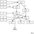
In
Um eine derartige Dekomposition vorzunehmen und zu spezifizieren verbindet die vorliegende Erfindung die Vorzüge der AUTOSAR Spezifikation im Allgemeinen, insbesondere aber der FIM Spezifikation, mit einem verteilten, mehrfachereignisfähigen und Graph-basierten Ansatz. Es wird hierbei von der flachen Subfunktionalitätsstruktur des AUTOSAR abgesehen. Die Subfunktionalitäten werden in Abhängigkeiten zueinander gebracht entsprechend ihren physikalischen Abhängigkeiten im reellen System. Dadurch entsteht ein Graph (d. h. eine geordnete Menge von Knoten und gerichteten Kanten), dessen Knoten die Ereignisse und Subfunktionalitäten darstellen. Hierbei wird auf die aus
Zweckmäßigerweise werden dabei die Monitore nicht anders als andere Subfunktionalitäten behandelt: sie werden über ihre eigenen Funktionsidentifikatoren, die in den Abhängigkeitsgraphen eingebaut sind, in ihrer Ausführung gesteuert. Somit entfällt automatisch und im Rahmen eines einheitlichen Konzepts die Notwendigkeit des nachträglichen Filterns der Überwachungsergebnisse. Der zuletzt ermittelte Ereignisstatus eines danach über seine Funktionsidentifikatoren deaktivierten Monitors verliert in der Regel seine Aussagekraft, da z. B. kein aktuelles Ergebnis vorliegt, wenn der dazugehörige Monitor inaktiv ist. Eine Ausnahme von dieser Regel stellen die sogenannten Power-On Monitore dar, die per Definition einmalig ausgeführt werden und deren Ergebnis für den gesamten Zyklus verwendet wird. Zweckmäßigerweise wird daher jeder Monitor dahingehend konfiguriert, ob der Status seines Ereignisses automatisch auf "NOTTESTED" gesetzt wird, sobald er per Funktionsidentifikator deaktiviert wird. Der "NOTTESTED" Status hat dann eine konfigurationsgemäße Auswirkung auf den abhängigen Teil des Graphen.The monitors are not treated any differently than other sub-functionalities: their execution is controlled by their own function identifiers, which are built into the dependency graph. This automatically eliminates the need for subsequent filtering of the monitoring results as part of a uniform concept. The last event status determined for a monitor that is subsequently deactivated via its function identifiers usually loses its significance, since, for example, there is no current result if the associated monitor is inactive. An exception to this rule are the so-called power-on monitors, which are by definition executed once and whose result is used for the entire cycle. It is therefore advisable to configure each monitor to determine whether the status of its event is automatically set to "NOTTESTED" as soon as it is deactivated via the function identifier. The "NOTTESTED" status then has a configuration-based effect on the dependent part of the graph.
Um beliebige Verfügbarkeitsstrategien realisieren zu können, ist die Unterstützung des Operators NOT - neben dem Operator AND - notwendig. Da die Unterstützung des Operators OR sich durchgehend negativ auf das Gesamtkonzept auswirken würde, kann stattdessen der Einsatz der De Morganschen Gesetze vorgesehen sein. Denn während der Operator NOT im Grunde ein 1-Bit AND mit Negierung ist, kann mittels des Operators OR die Umsetzung einer eigenen Logik erfolgen.In order to be able to implement any availability strategy, support for the NOT operator is necessary - in addition to the AND operator. Since support for the OR operator would have a consistently negative impact on the overall concept, the use of De Morgan's laws can be provided instead. While the NOT operator is basically a 1-bit AND with negation, the OR operator can be used to implement your own logic.
Ein derartiger Graph kann mit syntaktisch identischen Regeln beschrieben werden, z. B. mit: "Verbiete B wenn A {nicht} im <Status> ist", wobei B eine Subfunktionalität ist, die logische Negierung {nicht} optional ist und A eine Subfunktionalität mit den Status <verfügbar, nicht verfügbar> oder ein Ereignis mit den Status <FAILED, TESTED, NOTTESTED, PASSED, NOTPASSED, {...}> sein kann. Dieser Regelsatz stellt die Anforderungen der Systementwicklung auf der Softwareebene an die Softwareentwicklung im Sinne der ISO 26262 dar. Wegen der syntaktischen Identität aller Anforderungen kann daraus in einfacher Weise automatisch die entsprechende Konfiguration für die Software und die einschlägigen Testfälle für den automatisierten Modultest erzeugt werden, wobei der Konfigurations-Codegenerator und der Testfallgenerator bzw. die Testfallgeneratoren diversitär ausgeführt sind. Eine manuelle Programmierung zwecks Applikation auf Softwareebene entfällt somit.Such a graph can be described with syntactically identical rules, e.g. with: "Forbid B if A is {not} in <status>", where B is a sub-functionality, the logical negation is {not} optional and A can be a sub-functionality with the status <available, not available> or an event with the status <FAILED, TESTED, NOTTESTED, PASSED, NOTPASSED, {...}>. This set of rules represents the requirements of system development at the software level for software development in the sense of ISO 26262. Due to the syntactical identity of all requirements, the corresponding configuration for the software and the relevant test cases for the automated module test can be generated automatically in a simple manner, with the configuration code generator and the test case generator or the test case generators being implemented in a diverse manner. Manual programming for the purpose of application at the software level is therefore no longer necessary.
Der Einsatz von Subfunktionalitätsgraphen, wobei für die Subfunktionalitäten die einfachste Darstellung (logisch "verfügbar" oder "nicht verfügbar") zum Einsatz kommt, ist besonders vorteilhaft bei der Rückverfolgung der Ereignisse, die zu einem vorgegebenen (Nicht-) Verfügbarkeitsbild geführt haben.The use of subfunctionality graphs, where the simplest representation (logically "available" or "not available") is used for the subfunctionalities, is particularly advantageous when tracing the events that led to a given (non-)availability picture.
Der Einsatz von Subfunktionalitätsgraphen ist auch besonders vorteilhaft für die Realisierung verteilter Systeme. Verteilte Systeme sind Systeme, in denen ausgewählte Subfunktionalitäten partiell in unterschiedlichen Subfunktionalitätsgraphen an diversen Orten (diverse ECUs, Prozessoren, Cores (Prozessorkerne), Integritätslevel, asynchrone Tasks) berechnet werden und aus diesem Grunde eine Zusammenführung der Teilergebnisse notwendig ist. Eine verteilte Subfunktionalität kann systemweit nur dann als verfügbar angesehen werden, wenn alle Teilergebnisse auf "verfügbar" plädieren. Zur Zusammenführung der Teilergebnisse wird somit insbesondere der Operator AND verwendet, wie in
Die Ergebnisse der lokalen Monitore führen ohne Verzögerung zu den entsprechenden lokalen Verfügbarkeitsentscheidungen, unabhängig von der Verfügbarkeit der Kommunikationswege zu anderen Graphen bzw. dieser Graphen selbst. Bei Verfügbarkeit der Kommunikationswege ermöglicht der Austausch der minimalmöglichen Menge an Information (1 Bit bei Nichtberücksichtigung eventueller Maßnahmen zur Absicherung der Kommunikation) die Berücksichtigung aller Abhängigkeiten oberhalb der verteilten Subfunktionalität eines Graphen unterhalb dieser Subfunktionalität im anderen Graphen.
Ferner würde eine direkte bilaterale "Ver-UND-ung" der Subfunktionalitäten unweigerlich zum sogenannten "Deadlock" (d. h. eine blockierende Wartesituation zwischen den Subfunktionalitäten) führen: nachdem in einem der Graphen, möglicherweise nur kurzzeitig, ein Ereignis aufgetreten wäre, welches zur Nichtverfügbarkeit der verteilten Subfunktionalitäten führen würde, würde diese Subfunktionalität im Nachhinein über die Wechselwirkung der beiden Graphen dauerhaft im Zustand "nicht verfügbar" verharren und der möglichen Rücknahme des auslösenden Ereignisses nicht mehr folgen. Um diesem Effekt vorzubeugen, können verteilte Subfunktionalitäten zweistufig ausgeführt sein, wie in
In praktischer Weise können alle relevanten Aspekte der Subfunktionalitätsverteilung per Konfiguration eingestellt werden, wie z. B.: Die Zweistufigkeit der verteilten FIDs, die Einrichtung der notwendigen Kommunikationswege, die Einrichtung der Datenpakete samt Dateninhalte, die Sicherstellung der Kommunikationsfehlerfreiheit (End-to-End Protection mit wahlweiser Fehlerkorrektur) sowie die Überwachung der Kommunikationsfehlerfreiheit. Diese Konfiguration wird aus den Systementwicklungsanforderungen auf der Softwareebene abgeleitet und automatisch per Codegenerator zur Verfügung gestellt, ähnlich der Generierung der Testfälle für die Verteilungsaspekte. Auch hier entfällt der Bedarf manueller Programmierung zwecks Applikation auf Softwareebene. Zudem kann auch die Kommunikation mit / die Anbindung an beliebig viele Ereignisdiagnosemanager DEM bzw. beliebig viele nichtflüchtige Datenspeicher bzw. Non-Volatile Random-Access Memory (NVRAM)-Speicherorte auf der Anforderungsebene ohne Aufwände in der Programmierung bewerkstelligt werden. Ferner kann eine Verteilung der Graphen auf diverse Prozessoren und Steuergeräte (Electronic Control Units bzw. ECUs) erfolgen, die wahlweise mit oder ohne AUTOSAR Stack (heterogene Systeme) implementiert sind, um ihre Zusammenarbeit im Normalfall und ihre autarken Aktivitäten im Nicht-Normalfall zu gewährleisten.In a practical way, all relevant aspects of the subfunctionality distribution can be set via configuration, such as: the two-stage nature of the distributed FIDs, the setting up of the necessary communication paths, the setting up of the data packets including data contents, the ensuring of freedom from communication errors (end-to-end protection with optional error correction) and the monitoring of freedom from communication errors. This configuration is derived from the system development requirements at the software level and automatically made available via a code generator, similar to the generation the test cases for the distribution aspects. Here, too, there is no need for manual programming for the purpose of application at the software level. In addition, communication with/connection to any number of event diagnostic managers (DEM) or any number of non-volatile data memories or non-volatile random access memory (NVRAM) storage locations can be accomplished at the requirement level without any programming effort. Furthermore, the graphs can be distributed to various processors and control units (electronic control units or ECUs), which are implemented either with or without an AUTOSAR stack (heterogeneous systems) in order to ensure that they work together in normal cases and that they operate independently in non-normal cases.
Auf Basis der vorliegenden Erfindung wurde das Sicherheitskonzept einer AuDCU (Automated Driving Control Unit), wie in
Die verteilten Verfügbarkeitsmanagement-Instanzen können nicht unabhängig voneinander agieren, solange die ausführenden Prozessoren und die Kommunikation zwischen ihnen intakt sind. Dies erfolgt insbesondere, weil eine Verfügbarkeitsänderung in einer der Instanzen in der Regel Verfügbarkeitsänderungen in den anderen Instanzen nach sich zieht (Beispiel: wenn die elektrische Energieversorgung EPS der Performance-Verarbeitungspartition PPP über einen Abschaltpfad - als gepunkteter Pfeil in
Ferner wird die Kommunikation zwischen den Verfügbarkeitsmanagement-Instanzen überwacht. Das Ereignis, dass "die Kommunikation abgebrochen ist" führt in jeder plötzlich lokal gewordenen Instanz zu einer vordefinierten Reaktion. Über die Kommunikationswege zwischen den Verfügbarkeitsmanagement-Instanzen kann schließlich auch der Datenaustausch zu und von der Ereignisanalyse bzw. vom Ereignisdiagnosediagnosemanager DEM realisiert werden. Die beschriebene Funktionalität wird dabei aus einem gemeinsamen Satz an Anforderungen mittels Codegeneratoren sowohl als Konfiguration wie auch als Modultest automatisch auf die drei Prozessoren verteilt.Furthermore, communication between the availability management instances is monitored. The event that "communication has been interrupted" leads to a predefined reaction in each instance that suddenly becomes local. Finally, the communication paths between the availability management instances can also be used to exchange data to and from the event analysis or the event diagnosis manager DEM. The functionality described is automatically distributed to the three processors from a common set of requirements using code generators, both as a configuration and as a module test.
Die erfindungsgemäße Lösung eignet sich ferner zur kostengünstigen Realisierung verteilter Verfügbarkeitsmanagements in vielen denkbaren Situationen, in denen Systemgrenzen zu überwinden sind. Die Überwindung der Grenzen zwischen Prozessoren bzw. Mikrocontrollern µC sowie unterschiedlichen Integritätslevel innerhalb eines Prozessors und weitere Situationen wird in besonderem Maße vereinfacht, wie exemplarisch in
Ferner gewinnen die Grenzen zwischen unterschiedlichen ECUs angesichts der zunehmenden Komplexität der Fahrzeugsysteme zunehmend an Bedeutung. Systeme zum automatisierten bzw. autonomen Fahren bestehen mittlerweile aus einer Vielzahl von Prozessoren, die auf sehr viele, miteinander vernetzte ECUs der Sensoren (Kameras, Radargeräte etc.), der Aktuatoren (Lenkung, Bremse, Parkbremse etc.) sowie den performanten Rechenplattformen verteilt sind, die zusammen sehr komplexe sicherheitskritische verteilte Systeme bilden. Die vorliegende Erfindung ist hierbei besonders geeignet, sowohl die Verfügbarkeit der einzelnen Komponenten wie auch die Verfügbarkeit deren Verbundes effektiv und kostengünstig zu verwalten. Hierzu können die Anforderungen, aus denen die Konfigurationen und die Testfälle der Modultests für das Verfügbarkeitsmanagement automatisch erzeugt werden, wahlweise ECU bezogen, zentral oder gemischt (teils ECU bezogen, teils zentral) verwaltet werden. Es können dabei beliebig viele Diagnosen sowie persistente Speicherblöcke - sogar innerhalb eines Kontexts - unterstützt werden.Furthermore, the boundaries between different ECUs are becoming increasingly important in view of the increasing complexity of vehicle systems. Systems for automated or autonomous driving now consist of a large number of processors that are distributed across a large number of interconnected ECUs of the sensors (cameras, radar devices, etc.), the actuators (steering, brakes, parking brakes, etc.) and the high-performance computing platforms, which together form very complex, safety-critical distributed systems. The present invention is particularly suitable for managing both the availability of the individual components and the availability of their network effectively and cost-effectively. To this end, the requirements from which the configurations and test cases of the module tests for availability management are automatically generated can be managed either ECU-related, centrally or mixed (partly ECU-related, partly centrally). Any number of diagnoses and persistent memory blocks - even within one context - can be supported.
- PPPPPP
- Performance-Verarbeitungspartition bzw. Performance Processing PartitionPerformance Processing Partition
- SPPSPP
- Sicherheits-Verarbeitungspartition bzw. Safety Processing PartitionSafety Processing Partition
- EPSEPS
- elektrische Energieversorgung bzw. Electric Power Supplyelectric power supply or electric power supply
- EPEP
- Ethernet-PartitionEthernet partition
- EE
- EreignisEvent
- E1...9E1...9
- Ereignis 1...9Event 1...9
- FIDFID
- Funktionsidentifikator bzw. Function IdentifierFunction Identifier
- AvMAVM
- Verfügbarkeitsmanager bzw. Availability ManagerAvailability Manager
- ASILASIL
- Automotive Safety Integrity LevelAutomotive Safety Integrity Level
- DEMDEM
- Ereignisdiagnosemanager bzw. Diagnostic Event ManagerEvent Diagnostic Manager or Diagnostic Event Manager
- NVRAMNVRAM
- nichtflüchtige Datenspeicher bzw. Non-Volatile Random-Access Memorynon-volatile data storage or non-volatile random access memory
- QMQM
- Qualitätsmanagement bzw. Quality ManagementQuality Management
- AuDCUAuDCU
- Automated Driving Control UnitAutomated Driving Control Unit
- ECUECU
- Steuergerät bzw. Electronic Control UnitControl unit or Electronic Control Unit
- µCµC
- MikrocontrollerMicrocontroller
- P1P1
- Prozessor 1Processor 1
- P2P2
- Prozessor 2Processor 2
- G1G1
- Graph 1Graph 1
- G2G2
- Graph 2Graph 2
- G3G3
-
Graph 3
Graph 3 - A1A1
- Abschaltpfad 1Shutdown path 1
- A2A2
- Abschaltpfad 2Shutdown path 2
- C1C1
- Prozessorkern 1Processor core 1
- C2C2
- Prozessorkern 2Processor core 2
Claims (11)
- Method for ensuring and/or maintaining the function of a safety-critical overall system of a vehicle control system, in whichwhen an event (E, E1-E6) occurs in the overall system, the event (E, E1-E6) is analysed and sub-functionalities affected by the event (E, E1-E6) that has occurred are determined, andthe overall system is subdivided into mutually dependent sub-functionalities on the basis of the event analysis, whereinthe function of the overall system is ensured and/or maintained by controlling sub-functionalities depending on their availability, andthe sub-functionalities form graphs (G1, G2, G3), anda function identifier (FID) is provided, which identifies the respective subfunctionality and controls the latter in terms of its execution, whereina logical availability statement about the sub-functionalities, "available" or "not available", is made by means of the function identifier (FID) on the basis of the event analysis, andthe graphs (G1, G2, G3) of the sub-functionalities are processed jointly by graphs (G1, G2, G3) being connected on the basis of common sub-functionalities whose availability is calculated in a distributed manner, whereindistributed sub-functionalities are realized in a two-stage manner, wherein firstly local availabilities of the sub-functionalities of the graphs (G1, G2, G3) are determined and subsequently they are replaced with sub-functionalities of other graphs (G1, G2, G3) systemwide.
- Method according to Claim 1, characterized in that a plurality of graphs (G1, G2, G3) are calculated within the overall system.
- Method according to Claim 1 or 2, characterized in that the graphs (G1, G2, G3) of the sub-functionalities are coordinated with one another if communication between the latter is available.
- Method according to at least one of the preceding claims, characterized in that an event status of a monitor is determined on the basis of the event analysis, wherein the respective monitors are treated as sub-functionalities and are part of the system subdivision.
- Method according to Claim 4, characterized in that each monitor configured therefor is automatically set to a status which indicates that this monitor is not available as soon as it has been deactivated by the function identifier (FID).
- Method according to at least one of the preceding claims, characterized in that a software configuration and/or test cases is/are automatically generated from requirements in respect of the overall system.
- Method according to at least one of the preceding claims, characterized in that the overall system is divided into different partitions; in particular, the partitions comprise a performance processing partition (PPP) for processing, a safety processing partition (SPP) and an electric power supply (EPS), in particular for parameter and safety monitoring, and also an Ethernet partition (EP) for communication.
- Method according to Claim 7, characterized in that the processing partition (PPP), the safety processing partition (SPP) and the electric power supply (EPS) each have a processor and each monitor their processor resources and program execution.
- Method according to Claim 7 or 8, characterized in that mutual function monitoring of the processing partition (PPP), the safety processing partition (SPP) and the electric power supply (EPS) is provided.
- Overall system of a vehicle control system configured to ensure and/or maintain its function in particular with the aid of a method according to at least one of the preceding claims, in whichan availability manager (AvM) is provided, which, when an event (E, E1-E6) occurs in the overall system, analyses the event (E, E1-E6) and determines sub-functionalities affected by the event (E, E1-E6) that has occurred,the overall system is subdivided into mutually dependent sub-functionalities on the basis of the event analysis, whereinthe function of the overall system is ensured and/or maintained by controlling sub-functionalities depending on their availability, andthe sub-functionalities form graphs (G1, G2, G3), anda function identifier (FID) is provided, which identifies the respective subfunctionality and controls the latter in terms of its execution and is prepared to make a logical availability statement about the sub-functionalities, "available" or "not available", on the basis of the event analysis, andthe graphs (G1, G2, G3) of the sub-functionalities are processed jointly within a functional unit by the graphs (G1, G2, G3) being connected on the basis of common sub-functionalities whose availability is calculated in a distributed manner, whereindistributed sub-functionalities are realized in a two-stage manner, wherein firstly local availabilities of the sub-functionalities of the graphs (G1, G2, G3) are determined and subsequently they are replaced with sub-functionalities of other graphs (G1, G2, G3) systemwide.
- Computer program having program code for carrying out a method according to any of Claims 1-9 when the computer program is executed in a computer.
Applications Claiming Priority (2)
| Application Number | Priority Date | Filing Date | Title |
|---|---|---|---|
| DE102019208729.9A DE102019208729A1 (en) | 2019-06-14 | 2019-06-14 | Procedure for ensuring and maintaining the function of a safety-critical overall system |
| PCT/DE2020/200042 WO2020249169A1 (en) | 2019-06-14 | 2020-06-04 | Method for ensuring and maintaining the function of a complete safety-critical system |
Publications (2)
| Publication Number | Publication Date |
|---|---|
| EP3983897A1 EP3983897A1 (en) | 2022-04-20 |
| EP3983897B1 true EP3983897B1 (en) | 2024-04-24 |
Family
ID=71741574
Family Applications (1)
| Application Number | Title | Priority Date | Filing Date |
|---|---|---|---|
| EP20743960.5A Active EP3983897B1 (en) | 2019-06-14 | 2020-06-04 | Method for ensuring and maintaining the function of a complete safety-critical system |
Country Status (3)
| Country | Link |
|---|---|
| EP (1) | EP3983897B1 (en) |
| DE (1) | DE102019208729A1 (en) |
| WO (1) | WO2020249169A1 (en) |
Families Citing this family (2)
| Publication number | Priority date | Publication date | Assignee | Title |
|---|---|---|---|---|
| CN112699030B (en) * | 2020-12-29 | 2023-10-20 | 中国航空工业集团公司西安飞机设计研究所 | Automatic testing method for power supply partition software |
| DE102022212287A1 (en) * | 2022-11-18 | 2024-05-23 | Robert Bosch Gesellschaft mit beschränkter Haftung | Method and system for determining releases of control unit functions in a control unit of a technical device |
Family Cites Families (4)
| Publication number | Priority date | Publication date | Assignee | Title |
|---|---|---|---|---|
| DE102006056668A1 (en) | 2006-11-30 | 2008-06-05 | Continental Teves Ag & Co. Ohg | Method for ensuring or maintaining the function of a complex safety-critical overall system |
| US20090295559A1 (en) * | 2008-06-02 | 2009-12-03 | Gm Global Technology Operations, Inc. | Integrated hierarchical process for fault detection and isolation |
| FR2954537B1 (en) * | 2009-12-23 | 2012-08-10 | Thales Sa | METHOD AND DEVICE FOR PERFORMING A MAINTENANCE FUNCTION |
| US8806277B1 (en) * | 2012-02-01 | 2014-08-12 | Symantec Corporation | Systems and methods for fetching troubleshooting data |
-
2019
- 2019-06-14 DE DE102019208729.9A patent/DE102019208729A1/en active Pending
-
2020
- 2020-06-04 EP EP20743960.5A patent/EP3983897B1/en active Active
- 2020-06-04 WO PCT/DE2020/200042 patent/WO2020249169A1/en active Application Filing
Also Published As
| Publication number | Publication date |
|---|---|
| WO2020249169A1 (en) | 2020-12-17 |
| DE102019208729A1 (en) | 2020-12-17 |
| EP3983897A1 (en) | 2022-04-20 |
Similar Documents
| Publication | Publication Date | Title |
|---|---|---|
| DE102005014550B4 (en) | Brake by-wire control system | |
| EP2098926B1 (en) | Method and device for programming and/or configuring a safety controller | |
| EP3983897B1 (en) | Method for ensuring and maintaining the function of a complete safety-critical system | |
| DE102017218395A1 (en) | Method for fault-tolerant control of highly automated vehicles | |
| EP2099667B2 (en) | Method for ensuring or maintaining the function of a complex complete safety-critical system | |
| WO2008040641A2 (en) | Method and device for error management | |
| EP4235323A2 (en) | Method and device for automatically validating security functions on a modular security system | |
| WO2013007349A1 (en) | Method and system for the dynamic distribution of program functions in distributed control systems | |
| DE102017220845A1 (en) | Relocation of a function or application from a controller | |
| EP2216696B1 (en) | Method and communication system for configuring a communication module containing a logic module | |
| DE102019111564A1 (en) | METHOD AND SYSTEM FOR CONFIGURING FILTER OBJECTS FOR A CONTROLLER AREA NETWORK CONTROL | |
| DE102012212680A1 (en) | Method and system for fault-tolerant control of actuators for a limited time based on pre-calculated values | |
| WO2005001692A2 (en) | Method and device for monitoring a distributed system | |
| EP3470939A1 (en) | Method and devices for monitoring the security integrity of a security function provided by a security system | |
| DE102007046706A1 (en) | Control device for vehicles | |
| DE102017123911A1 (en) | Method and apparatus for monitoring the response time of a security function provided by a security system | |
| EP4040034A1 (en) | Safety device and safety method for monitoring a machine | |
| EP3399375B1 (en) | Method for configuring control devices | |
| DE102017212560A1 (en) | Method for fail-safe performance of a safety-related function | |
| EP1536328A2 (en) | Data processing system with automatable management and method for automated management of a data processing system | |
| DE102019204452A1 (en) | Method and device for operating a control device in a network of control devices | |
| DE102019134872B4 (en) | Improvement of the operating parameters of a computing system in the vehicle | |
| WO2011113405A1 (en) | Controller arrangement | |
| EP1967920A1 (en) | Softwareupdate method for FPGA-based automation systems | |
| DE102022212057A1 (en) | Method for analyzing functional paths for an embedded system, data processing device, computer program and computer-readable data carrier |
Legal Events
| Date | Code | Title | Description |
|---|---|---|---|
| STAA | Information on the status of an ep patent application or granted ep patent |
Free format text: STATUS: UNKNOWN |
|
| STAA | Information on the status of an ep patent application or granted ep patent |
Free format text: STATUS: THE INTERNATIONAL PUBLICATION HAS BEEN MADE |
|
| PUAI | Public reference made under article 153(3) epc to a published international application that has entered the european phase |
Free format text: ORIGINAL CODE: 0009012 |
|
| STAA | Information on the status of an ep patent application or granted ep patent |
Free format text: STATUS: REQUEST FOR EXAMINATION WAS MADE |
|
| 17P | Request for examination filed |
Effective date: 20220114 |
|
| AK | Designated contracting states |
Kind code of ref document: A1 Designated state(s): AL AT BE BG CH CY CZ DK EE ES FI FR GB GR HR HU IE IS IT LI LT LU LV MC MK MT NL NO PL PT RO RS SE SI SK SM TR |
|
| RAP1 | Party data changed (applicant data changed or rights of an application transferred) |
Owner name: CONTINENTAL AUTONOMOUS MOBILITY GERMANY GMBH |
|
| DAV | Request for validation of the european patent (deleted) | ||
| DAX | Request for extension of the european patent (deleted) | ||
| STAA | Information on the status of an ep patent application or granted ep patent |
Free format text: STATUS: EXAMINATION IS IN PROGRESS |
|
| 17Q | First examination report despatched |
Effective date: 20230704 |
|
| RBV | Designated contracting states (corrected) |
Designated state(s): AL AT BE BG CH CY CZ DE DK EE ES FI FR GB GR HR HU IE IS IT LI LT LU LV MC MK MT NL NO PL PT RO RS SE SI SK SM TR |
|
| GRAP | Despatch of communication of intention to grant a patent |
Free format text: ORIGINAL CODE: EPIDOSNIGR1 |
|
| STAA | Information on the status of an ep patent application or granted ep patent |
Free format text: STATUS: GRANT OF PATENT IS INTENDED |
|
| INTG | Intention to grant announced |
Effective date: 20231205 |
|
| GRAS | Grant fee paid |
Free format text: ORIGINAL CODE: EPIDOSNIGR3 |
|
| GRAA | (expected) grant |
Free format text: ORIGINAL CODE: 0009210 |
|
| STAA | Information on the status of an ep patent application or granted ep patent |
Free format text: STATUS: THE PATENT HAS BEEN GRANTED |
|
| AK | Designated contracting states |
Kind code of ref document: B1 Designated state(s): AL AT BE BG CH CY CZ DE DK EE ES FI FR GB GR HR HU IE IS IT LI LT LU LV MC MK MT NL NO PL PT RO RS SE SI SK SM TR |
|
| REG | Reference to a national code |
Ref country code: GB Ref legal event code: FG4D Free format text: NOT ENGLISH |
|
| REG | Reference to a national code |
Ref country code: CH Ref legal event code: EP |
|
| REG | Reference to a national code |
Ref country code: DE Ref legal event code: R096 Ref document number: 502020007770 Country of ref document: DE |
|
| REG | Reference to a national code |
Ref country code: IE Ref legal event code: FG4D Free format text: LANGUAGE OF EP DOCUMENT: GERMAN |