EP3981978A1 - Method for operating a hydrogen fuelled combustion engine - Google Patents
Method for operating a hydrogen fuelled combustion engine Download PDFInfo
- Publication number
- EP3981978A1 EP3981978A1 EP20200941.1A EP20200941A EP3981978A1 EP 3981978 A1 EP3981978 A1 EP 3981978A1 EP 20200941 A EP20200941 A EP 20200941A EP 3981978 A1 EP3981978 A1 EP 3981978A1
- Authority
- EP
- European Patent Office
- Prior art keywords
- chamber
- hydrogen fuel
- main combustion
- combustion
- cylinder
- Prior art date
- Legal status (The legal status is an assumption and is not a legal conclusion. Google has not performed a legal analysis and makes no representation as to the accuracy of the status listed.)
- Pending
Links
- UFHFLCQGNIYNRP-UHFFFAOYSA-N Hydrogen Chemical compound [H][H] UFHFLCQGNIYNRP-UHFFFAOYSA-N 0.000 title claims abstract description 141
- 229910052739 hydrogen Inorganic materials 0.000 title claims abstract description 141
- 239000001257 hydrogen Substances 0.000 title claims abstract description 141
- 238000002485 combustion reaction Methods 0.000 title claims abstract description 140
- 238000000034 method Methods 0.000 title claims abstract description 23
- 239000000446 fuel Substances 0.000 claims abstract description 142
- 239000012530 fluid Substances 0.000 claims abstract description 8
- 238000002347 injection Methods 0.000 claims description 5
- 239000007924 injection Substances 0.000 claims description 5
- 230000006835 compression Effects 0.000 claims description 4
- 238000007906 compression Methods 0.000 claims description 4
- 230000002159 abnormal effect Effects 0.000 description 17
- 239000000203 mixture Substances 0.000 description 14
- 239000000126 substance Substances 0.000 description 5
- 238000010586 diagram Methods 0.000 description 2
- 239000002803 fossil fuel Substances 0.000 description 2
- 230000000116 mitigating effect Effects 0.000 description 2
- 238000010791 quenching Methods 0.000 description 2
- 230000000171 quenching effect Effects 0.000 description 2
- 230000008859 change Effects 0.000 description 1
- 238000006243 chemical reaction Methods 0.000 description 1
- 230000000694 effects Effects 0.000 description 1
- 229930195733 hydrocarbon Natural products 0.000 description 1
- 150000002430 hydrocarbons Chemical class 0.000 description 1
- 230000007062 hydrolysis Effects 0.000 description 1
- 238000006460 hydrolysis reaction Methods 0.000 description 1
- 230000007246 mechanism Effects 0.000 description 1
- 230000007935 neutral effect Effects 0.000 description 1
- 230000008569 process Effects 0.000 description 1
- 230000009467 reduction Effects 0.000 description 1
- 230000035945 sensitivity Effects 0.000 description 1
Images


Classifications
-
- F—MECHANICAL ENGINEERING; LIGHTING; HEATING; WEAPONS; BLASTING
- F02—COMBUSTION ENGINES; HOT-GAS OR COMBUSTION-PRODUCT ENGINE PLANTS
- F02B—INTERNAL-COMBUSTION PISTON ENGINES; COMBUSTION ENGINES IN GENERAL
- F02B19/00—Engines characterised by precombustion chambers
- F02B19/10—Engines characterised by precombustion chambers with fuel introduced partly into pre-combustion chamber, and partly into cylinder
- F02B19/1019—Engines characterised by precombustion chambers with fuel introduced partly into pre-combustion chamber, and partly into cylinder with only one pre-combustion chamber
- F02B19/108—Engines characterised by precombustion chambers with fuel introduced partly into pre-combustion chamber, and partly into cylinder with only one pre-combustion chamber with fuel injection at least into pre-combustion chamber, i.e. injector mounted directly in the pre-combustion chamber
-
- F—MECHANICAL ENGINEERING; LIGHTING; HEATING; WEAPONS; BLASTING
- F02—COMBUSTION ENGINES; HOT-GAS OR COMBUSTION-PRODUCT ENGINE PLANTS
- F02B—INTERNAL-COMBUSTION PISTON ENGINES; COMBUSTION ENGINES IN GENERAL
- F02B19/00—Engines characterised by precombustion chambers
- F02B19/10—Engines characterised by precombustion chambers with fuel introduced partly into pre-combustion chamber, and partly into cylinder
- F02B19/1019—Engines characterised by precombustion chambers with fuel introduced partly into pre-combustion chamber, and partly into cylinder with only one pre-combustion chamber
- F02B19/1023—Engines characterised by precombustion chambers with fuel introduced partly into pre-combustion chamber, and partly into cylinder with only one pre-combustion chamber pre-combustion chamber and cylinder being fed with fuel-air mixture(s)
- F02B19/1028—Engines characterised by precombustion chambers with fuel introduced partly into pre-combustion chamber, and partly into cylinder with only one pre-combustion chamber pre-combustion chamber and cylinder being fed with fuel-air mixture(s) pre-combustion chamber and cylinder having both intake ports or valves, e.g. HONDS CVCC
- F02B19/1057—Engines characterised by precombustion chambers with fuel introduced partly into pre-combustion chamber, and partly into cylinder with only one pre-combustion chamber pre-combustion chamber and cylinder being fed with fuel-air mixture(s) pre-combustion chamber and cylinder having both intake ports or valves, e.g. HONDS CVCC with fuel injectors disposed upstream of intake valves
-
- F—MECHANICAL ENGINEERING; LIGHTING; HEATING; WEAPONS; BLASTING
- F02—COMBUSTION ENGINES; HOT-GAS OR COMBUSTION-PRODUCT ENGINE PLANTS
- F02B—INTERNAL-COMBUSTION PISTON ENGINES; COMBUSTION ENGINES IN GENERAL
- F02B19/00—Engines characterised by precombustion chambers
- F02B19/12—Engines characterised by precombustion chambers with positive ignition
-
- F—MECHANICAL ENGINEERING; LIGHTING; HEATING; WEAPONS; BLASTING
- F02—COMBUSTION ENGINES; HOT-GAS OR COMBUSTION-PRODUCT ENGINE PLANTS
- F02D—CONTROLLING COMBUSTION ENGINES
- F02D41/00—Electrical control of supply of combustible mixture or its constituents
- F02D41/0025—Controlling engines characterised by use of non-liquid fuels, pluralities of fuels, or non-fuel substances added to the combustible mixtures
- F02D41/0027—Controlling engines characterised by use of non-liquid fuels, pluralities of fuels, or non-fuel substances added to the combustible mixtures the fuel being gaseous
-
- F—MECHANICAL ENGINEERING; LIGHTING; HEATING; WEAPONS; BLASTING
- F02—COMBUSTION ENGINES; HOT-GAS OR COMBUSTION-PRODUCT ENGINE PLANTS
- F02M—SUPPLYING COMBUSTION ENGINES IN GENERAL WITH COMBUSTIBLE MIXTURES OR CONSTITUENTS THEREOF
- F02M21/00—Apparatus for supplying engines with non-liquid fuels, e.g. gaseous fuels stored in liquid form
- F02M21/02—Apparatus for supplying engines with non-liquid fuels, e.g. gaseous fuels stored in liquid form for gaseous fuels
- F02M21/0203—Apparatus for supplying engines with non-liquid fuels, e.g. gaseous fuels stored in liquid form for gaseous fuels characterised by the type of gaseous fuel
- F02M21/0206—Non-hydrocarbon fuels, e.g. hydrogen, ammonia or carbon monoxide
-
- F—MECHANICAL ENGINEERING; LIGHTING; HEATING; WEAPONS; BLASTING
- F02—COMBUSTION ENGINES; HOT-GAS OR COMBUSTION-PRODUCT ENGINE PLANTS
- F02M—SUPPLYING COMBUSTION ENGINES IN GENERAL WITH COMBUSTIBLE MIXTURES OR CONSTITUENTS THEREOF
- F02M21/00—Apparatus for supplying engines with non-liquid fuels, e.g. gaseous fuels stored in liquid form
- F02M21/02—Apparatus for supplying engines with non-liquid fuels, e.g. gaseous fuels stored in liquid form for gaseous fuels
- F02M21/0218—Details on the gaseous fuel supply system, e.g. tanks, valves, pipes, pumps, rails, injectors or mixers
- F02M21/0248—Injectors
- F02M21/0275—Injectors for in-cylinder direct injection, e.g. injector combined with spark plug
-
- F—MECHANICAL ENGINEERING; LIGHTING; HEATING; WEAPONS; BLASTING
- F02—COMBUSTION ENGINES; HOT-GAS OR COMBUSTION-PRODUCT ENGINE PLANTS
- F02M—SUPPLYING COMBUSTION ENGINES IN GENERAL WITH COMBUSTIBLE MIXTURES OR CONSTITUENTS THEREOF
- F02M21/00—Apparatus for supplying engines with non-liquid fuels, e.g. gaseous fuels stored in liquid form
- F02M21/02—Apparatus for supplying engines with non-liquid fuels, e.g. gaseous fuels stored in liquid form for gaseous fuels
- F02M21/0218—Details on the gaseous fuel supply system, e.g. tanks, valves, pipes, pumps, rails, injectors or mixers
- F02M21/0248—Injectors
- F02M21/0278—Port fuel injectors for single or multipoint injection into the air intake system
-
- F—MECHANICAL ENGINEERING; LIGHTING; HEATING; WEAPONS; BLASTING
- F02—COMBUSTION ENGINES; HOT-GAS OR COMBUSTION-PRODUCT ENGINE PLANTS
- F02P—IGNITION, OTHER THAN COMPRESSION IGNITION, FOR INTERNAL-COMBUSTION ENGINES; TESTING OF IGNITION TIMING IN COMPRESSION-IGNITION ENGINES
- F02P13/00—Sparking plugs structurally combined with other parts of internal-combustion engines
-
- Y—GENERAL TAGGING OF NEW TECHNOLOGICAL DEVELOPMENTS; GENERAL TAGGING OF CROSS-SECTIONAL TECHNOLOGIES SPANNING OVER SEVERAL SECTIONS OF THE IPC; TECHNICAL SUBJECTS COVERED BY FORMER USPC CROSS-REFERENCE ART COLLECTIONS [XRACs] AND DIGESTS
- Y02—TECHNOLOGIES OR APPLICATIONS FOR MITIGATION OR ADAPTATION AGAINST CLIMATE CHANGE
- Y02T—CLIMATE CHANGE MITIGATION TECHNOLOGIES RELATED TO TRANSPORTATION
- Y02T10/00—Road transport of goods or passengers
- Y02T10/10—Internal combustion engine [ICE] based vehicles
- Y02T10/12—Improving ICE efficiencies
-
- Y—GENERAL TAGGING OF NEW TECHNOLOGICAL DEVELOPMENTS; GENERAL TAGGING OF CROSS-SECTIONAL TECHNOLOGIES SPANNING OVER SEVERAL SECTIONS OF THE IPC; TECHNICAL SUBJECTS COVERED BY FORMER USPC CROSS-REFERENCE ART COLLECTIONS [XRACs] AND DIGESTS
- Y02—TECHNOLOGIES OR APPLICATIONS FOR MITIGATION OR ADAPTATION AGAINST CLIMATE CHANGE
- Y02T—CLIMATE CHANGE MITIGATION TECHNOLOGIES RELATED TO TRANSPORTATION
- Y02T10/00—Road transport of goods or passengers
- Y02T10/10—Internal combustion engine [ICE] based vehicles
- Y02T10/30—Use of alternative fuels, e.g. biofuels
Definitions
- the present invention relates to a method for operating an internal combustion engine using hydrogen fuel and to a hydrogen fuelled internal combustion engine according to the independent claim.
- the invention lies in the technical field of internal combustion engines using hydrogen fuel and having a pre-chamber for the ignition of the combustion chamber by use of turbulent jet ignition.
- abnormal combustion refers to an uncontrolled combustion of fuel in engines caused by undesired auto-ignition. This is accompanied by pressure peaks, which can damage pistons, bearings, cylinder head, valves, etc. Consequently, forms of abnormal combustion need to be prevented.
- a method of controlling knock is by reducing the combustion duration. This reduces the residence time that the unburned fuel/air mixture ahead of the flame experiences at high temperature, thereby reducing its likelihood to auto-ignite prior to normal consumption by the initiated flame.
- the first is to reduce bulk in-cylinder temperature.
- the second is to alter the air/hydrogen fuel mixture's composition in order to increase the temperature threshold at which successful ignition of hydrogen will occur.
- the fuel-agnostic mass ratio of air to fuel (air-fuel ratio / stoichiometric air-fuel ratio) present in a combustion chamber, commonly denoted as lambda ( ⁇ ), indicates the mass ratio of air to fuel relative to the respective stoichiometrically ideal ratio for a theoretically complete combustion process.
- the ratio becomes stoichiometric when just enough air is provided to combust the fuel completely.
- ⁇ 1.
- a lower air/fuel ratio ( ⁇ ⁇ 1) is called “rich”
- a higher air/fuel ratio ( ⁇ > 1) is called “lean”.
- the present invention distinguishes between the ⁇ in the pre-chamber and in the main combustion chamber. Conventionally ⁇ being far from 1 results in a poor ignition quality of the mixture and ultimately to ⁇ limit values, which, if they are violated, lead to a poor combustion performance.
- Turbulent jet ignition enables the engine to operate within wider ⁇ limit values compared to spark ignited engines where ignition is achieved only via traditional spark plugs.
- a prior art internal combustion engine for fossil fuel employing an ignition system for turbulent jet ignition is disclosed in US 2012 103 302 A1 .
- the internal combustion engine has an engine block with cylinders. Each cylinder has a cylinder head bordering a main combustion chamber in which the main air fuel charge is ignited. A piston is arranged bordering the combustion chamber, which is connected via a rod at a crankshaft to allow a reciprocal movement.
- Each cylinder roof defines an intake opening and an exhaust opening. The intake and exhaust openings are opened and closed via cam driven valves to provide fluid communication between the cylinder and an intake manifold and an exhaust manifold.
- the internal combustion engine also includes a fuel injector mounted in the intake manifold as a means of introducing the main fuel/air charge into the combustion chamber through the intake port.
- the ignition device has an igniter portion and an injector arranged to face an inner pre-chamber volume.
- the pre-chamber is shaped to form a nozzle having a plurality of orifices disposed spaced from one another and providing fluid communication between the pre-chamber and the combustion chamber.
- the igniter portion ignites the fuel in the pre-chamber.
- the orifice diameter is kept small to promote flame quenching as the combustion products exit out of the pre-chamber into the main combustion chamber. Flame quenching means that the partially combusted pre-chamber products are forced through the small orifices of the pre-chamber. The combustion products are extinguished, but disperse through the main combustion chamber, then react with the main fuel charge and initiate combustion in the main combustion chamber at multiple locations through chemical, thermal and turbulent effects at some distance from the pre-chamber nozzle.
- the pre-chamber of this ignition device includes a plurality of orifices of an advantageous design (i.e. diameter size) to provide a fluid communication between the pre-chamber volume and the main chamber volume.
- Hydrogen fuel refers to hydrogen fuel blends containing more than 50% hydrogen by volume.
- an (actively hydrogen fuelled) pre-chamber combustor active jet ignition decouples the ⁇ in the pre-chamber from the ⁇ in the main combustion chamber. This allows tuning ⁇ in the pre-chamber for an optimal spark event to occur in the pre-chamber, the highly reactive products of which subsequently initiate the second combustion event in the main combustion chamber.
- the ⁇ in the main combustion chamber can be tuned independently from the ⁇ in the pre-chamber in such a way that both abnormal combustion in the pre-chamber and in the main combustion chamber are mitigated.
- the step of introducing hydrogen fuel in the pre-chamber is conducted after the step of introducing hydrogen fuel in the main combustion chamber. This allows for separately controlling the air/hydrogen fuel mixture (and ⁇ ) in the pre-chamber and the main combustion chamber.
- the step of introducing hydrogen fuel in the pre-chamber and the step of introducing hydrogen fuel in the main combustion chamber are conducted at least partially overlapping. This allows improved simultaneous controlling of the air/hydrogen fuel mixture in the main combustion chamber and the pre-chamber.
- the step of introducing hydrogen fuel in the pre-chamber comprises that a portion of the hydrogen fuel introduced into the main combustion chamber enters the pre-chamber.
- the step of introducing hydrogen fuel in the pre-chamber comprises that a portion of the hydrogen fuel introduced into the main combustion chamber enters the pre-chamber during a compression stroke of the piston in the cylinder.
- the step of introducing hydrogen fuel in the pre-chamber comprises that a portion of the hydrogen fuel introduced into the main combustion chamber enters the pre-chamber partially during an intake stroke of the piston in the cylinder.
- the step of introducing hydrogen fuel in the pre-chamber comprises that hydrogen fuel is injected into the pre-chamber by the hydrogen fuel injector. This allows to reduce the air/hydrogen fuel ratio ⁇ in the pre-chamber and to compensate for a lean lambda of the hydrogen fuel entering the pre-chamber from the main combustion chamber.
- the step of introducing hydrogen fuel in the pre-chamber comprises multiple injections of hydrogen fuel via the fuel injector in the pre-chamber. This allows for adding more hydrogen fuel and, hence, to provide a rich mixture to be ignited in the pre-chamber which improves flammability of the hydrogen fuel-air mixture.
- a particularly preferred aspect relates to the amount of injected hydrogen fuel in the pre-chamber being chosen so that the air/hydrogen fuel ratio ⁇ inside the pre-chamber is within the range 0.25 ⁇ ⁇ ⁇ 0.4 at the time of igniting the injected hydrogen fuel in the pre-chamber.
- This range of ⁇ is selected to reduce the combustion temperatures within the pre-chamber to mitigate abnormal combustion (e.g. pre-ignition, knock) in the pre-chamber.
- this range of ⁇ is selected for optimal pre-chamber combustion duration to mitigate abnormal combustion (e.g. pre-ignition, knock) in pre-chamber and in the main chamber.
- the amount of injected hydrogen fuel in the pre-chamber is chosen so that the air/hydrogen fuel ratio ⁇ inside the pre-chamber is within the range 1.4 ⁇ ⁇ ⁇ 2.5 at the time of igniting the injected hydrogen fuel in the pre-chamber.
- This range of ⁇ is selected to reduce the combustion temperatures within the pre-chamber to mitigate abnormal combustion (e.g. pre-ignition, knock) in the pre-chamber.
- this range of ⁇ is selected for optimal pre-chamber combustion duration to mitigate abnormal combustion (e.g. pre-ignition, knock) in the pre-chamber and the main chamber.
- the injection of hydrogen fuel in the pre-chamber is carried out so that the air/hydrogen fuel ratio ⁇ inside the pre-chamber is maintained at 1.4 ⁇ ⁇ during the steps of injecting hydrogen fuel in the pre-chamber until igniting the injected hydrogen fuel in the pre-chamber.
- FIG. 1 an example for internal combustion engine 1 using hydrogen fuel is given which shows in the present illustration one cylinder 2 and a piston 3 supported at a crankshaft 5 for repeated reciprocal movement in the cylinder 2.
- Cylinder 2 and piston 3 define a main combustion chamber 21.
- the internal combustion engine 1 has an ignition device 4 arranged to face the combustion chamber 21.
- the ignition device 4 has an igniter portion 42 and a hydrogen fuel injector 43 which are both arranged at a pre-chamber 41 so as to form a part of the inner volume of the pre-chamber 41.
- the pre-chamber 41 has a plurality of orifices 44 for providing fluid communication between the inner volume of pre-chamber 41 and the inner volume of main combustion chamber 21.
- the hydrogen fuel is introduced in main combustion chamber 21. Subsequently, hydrogen fuel is introduced in the pre-chamber 41 in such a way that hydrogen fuel enters the pre-chamber 41 from the main combustion chamber 21 during a compression stroke of the piston 3 in the cylinder 2. More hydrogen fuel is introduced in the pre-chamber 41 by injecting hydrogen fuel into the pre-chamber 41 by the hydrogen fuel injector 43. The introduced hydrogen fuel is ignited in the pre-chamber 41 via the igniter portion 42. The resulting pressure increase in the pre-chamber 41 causes this chemical energy to be rapidly transferred to the main combustion chamber 21 in the form of jets, which are formed when the contents flow through the orifices 44 to the main combustion chamber 21 for combusting the introduced hydrogen fuel in the main combustion chamber 21.
- Fig. 1 The method for operating a hydrogen fuelled combustion engine (as shown in Fig. 1 ) is illustrated by the block diagram of Fig. 2 .
- the reference numbers of Fig. 1 and Fig. 2 correspond to each other so that in the following the reference numbers shown in Fig. 1 are used for the description of Fig. 2 .
- Step A relates to introducing hydrogen fuel in the main combustion chamber 21.
- step B hydrogen fuel is introduced in the pre-chamber 41 in such a way that hydrogen fuel enters the pre-chamber 41 from the main combustion chamber 21 during a compression stroke of the piston 3 in the cylinder 2.
- step C hydrogen fuel is injected into the pre-chamber 41 via the hydrogen fuel injector 43.
- This allows to reduce the air/hydrogen fuel ratio ⁇ in the pre-chamber 41 and to compensate for a lean lambda of the hydrogen fuel entering the pre-chamber 41 from the main combustion chamber 21.
- the present example comprises multiple injections (Step C, Step C, Step C,...) of hydrogen fuel via the hydrogen fuel injector 43 in the pre-chamber 41.
- the provided air/hydrogen fuel mixture in the pre-chamber 41 will become richer after every injection which improves flammability of the hydrogen fuel-air mixture.
- the introduced hydrogen fuel is ignited in the pre-chamber 41 via the igniter portion 42 in step D.
- chemical energy is rapidly transferred to the main combustion chamber 21 in the form of jets, which are formed when the contents flow through the orifices 44 to the main combustion chamber 21 for combusting the introduced hydrogen fuel in the main combustion chamber 21.
- Fig. 3 is a plot that shows the pre-chamber combustion duration versus pre-chamber lambda at the time of igniting the injected hydrogen fuel in the pre-chamber, i.e. at spark timing.
- the amount of injected hydrogen fuel in the pre-chamber is chosen so that the normalized air/hydrogen fuel ratio ⁇ inside the pre-chamber is within the range 0.25 ⁇ ⁇ ⁇ 0.4 or within the range 1.4 ⁇ ⁇ ⁇ 2.5 at the time of igniting the injected hydrogen fuel in the pre-chamber, i.e. at spark timing.
- these ranges of ⁇ are selected for optimal pre-chamber combustion duration to mitigate abnormal combustion (e.g. pre-ignition, knock).
- pre-chamber combustion leads to a high likelihood of poor engine performance, e.g. because of unacceptable combustion instability or misfires in either the pre-chamber or main chamber, or excessively fast pre-chamber combustion leads to abnormal combustion in the pre-chamber, e.g. knocking.
- Fig. 4 is a plot that shows the early burn duration in the main combustion chamber (duration in crank angle degrees of the time it takes the main chamber to consume from 0% to 10% of the fuel mass present) versus pre-chamber combustion duration.
- Region A identifies the area where overly slow pre-chamber combustion produces overly slow early combustion in the main chamber, leading to a high likelihood of poor engine performance, e.g. unacceptable combustion instability or misfires in the pre-chamber or main chamber.
- Region B identifies the area where an excessively fast pre-chamber combustion event can lead to abnormal combustion in the pre-chamber, e.g. knocking.
- Fig. 5 is a plot that shows simulated peak combustion temperature of contents interior to the pre-chamber versus pre-chamber lambda ⁇ at the time of igniting the injected hydrogen fuel in the pre-chamber, i.e. at spark timing.
- High combustion temperatures within the range 0.4 ⁇ ⁇ ⁇ 1.4 increase the likelihood of abnormal combustion, e.g. pre-ignition or knock, occurring in subsequent engine cycles.
- the amount of injected hydrogen fuel in the pre-chamber is chosen so that the normalized air/hydrogen fuel ratio ⁇ inside the pre-chamber is within the range 0.25 ⁇ ⁇ ⁇ 0.4 or within the range 1.4 ⁇ ⁇ ⁇ 2.5 at the time of igniting the injected hydrogen fuel in the pre-chamber, i.e. at spark timing. Both ranges of ⁇ are selected to reduce the combustion temperatures within the pre-chamber to an extent to mitigate abnormal combustion, e.g. pre-ignition or knock.
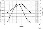
- Fig. 6 is a plot that shows the constant-volume adiabatic flame temperature and the flame speed versus lambda ⁇ .
- the plot serves to indicate a general relationship of hydrogen fuel properties to lambda, applicable for example to optimize the normalized air/hydrogen fuel ratio ⁇ inside the pre-chamber at the time of igniting the injected hydrogen fuel in the pre-chamber, i.e. at spark timing.
Landscapes
- Engineering & Computer Science (AREA)
- Chemical & Material Sciences (AREA)
- Combustion & Propulsion (AREA)
- Mechanical Engineering (AREA)
- General Engineering & Computer Science (AREA)
- Chemical Kinetics & Catalysis (AREA)
- General Chemical & Material Sciences (AREA)
- Oil, Petroleum & Natural Gas (AREA)
- Combustion Methods Of Internal-Combustion Engines (AREA)
- Output Control And Ontrol Of Special Type Engine (AREA)
- Fuel-Injection Apparatus (AREA)
- Electrical Control Of Air Or Fuel Supplied To Internal-Combustion Engine (AREA)
Abstract
- providing an internal combustion engine 1 having at least one cylinder 2 and a piston 3 supported at a crankshaft 5 for repeated reciprocal movement in the cylinder 2 so as to define a main combustion chamber 21, the internal combustion engine 1 further having an ignition device 4 arranged in said cylinder 2 with an igniter portion 42 and a hydrogen fuel injector 43 which are both arranged at a pre-chamber 41, wherein the pre-chamber 41 has a plurality of orifices 44 for providing fluid communication between said pre-chamber 41 and the main combustion chamber 21; and
- operating the engine in cycles comprising the following steps:
- introducing hydrogen fuel in the pre-chamber 41;
- introducing hydrogen fuel in the main combustion chamber 21; and
- igniting the introduced hydrogen fuel in the pre-chamber 41 for combusting the introduced hydrogen fuel in the main combustion chamber 21.
Description
- The present invention relates to a method for operating an internal combustion engine using hydrogen fuel and to a hydrogen fuelled internal combustion engine according to the independent claim.
- The invention lies in the technical field of internal combustion engines using hydrogen fuel and having a pre-chamber for the ignition of the combustion chamber by use of turbulent jet ignition.
- Internal combustion engines using hydrogen fuel contribute to climate change mitigation, since hydrogen is a substitute for fossil fuels such as gasoline or diesel. In particular, a largely CO2 neutral supply of hydrogen can be achieved by using hydrogen produced in hydrolysis processes using renewable energies. In addition, the emission of CO2 is avoided in hydrogen combustion engines.
- However, the unique fuel properties of hydrogen such as low minimum ignition energy, wide flammability limits, and simple low-temperature kinetics make it prone to abnormal combustion. One form of abnormal combustion is knock, which refers to an uncontrolled combustion of fuel in engines caused by undesired auto-ignition. This is accompanied by pressure peaks, which can damage pistons, bearings, cylinder head, valves, etc. Consequently, forms of abnormal combustion need to be prevented.
- For conventional fuels, such as gasoline, a method of controlling knock is by reducing the combustion duration. This reduces the residence time that the unburned fuel/air mixture ahead of the flame experiences at high temperature, thereby reducing its likelihood to auto-ignite prior to normal consumption by the initiated flame.
- However, with hydrogen fuel abnormal combustion occurs very quickly once the hydrogen fuel reaches a certain temperature threshold. Unlike more complex hydrocarbons, hydrogen's low-temperature kinetics are such that it has minimal sensitivity to the residence time of the unburned air/hydrogen fuel mixture, meaning that combustion duration reduction is significantly less effective as a mechanism for knock mitigation.
- There are therefore two effective methods for reducing abnormal combustion with hydrogen fuel. The first is to reduce bulk in-cylinder temperature. The second is to alter the air/hydrogen fuel mixture's composition in order to increase the temperature threshold at which successful ignition of hydrogen will occur.
- The fuel-agnostic mass ratio of air to fuel (air-fuel ratio / stoichiometric air-fuel ratio) present in a combustion chamber, commonly denoted as lambda (λ), indicates the mass ratio of air to fuel relative to the respective stoichiometrically ideal ratio for a theoretically complete combustion process. The ratio becomes stoichiometric when just enough air is provided to combust the fuel completely. This defines λ = 1. A lower air/fuel ratio (λ < 1) is called "rich", whereas a higher air/fuel ratio (λ > 1) is called "lean". The present invention distinguishes between the λ in the pre-chamber and in the main combustion chamber. Conventionally λ being far from 1 results in a poor ignition quality of the mixture and ultimately to λ limit values, which, if they are violated, lead to a poor combustion performance.
- Turbulent jet ignition enables the engine to operate within wider λ limit values compared to spark ignited engines where ignition is achieved only via traditional spark plugs. A prior art internal combustion engine for fossil fuel employing an ignition system for turbulent jet ignition is disclosed in
US 2012 103 302 A1 . The internal combustion engine has an engine block with cylinders. Each cylinder has a cylinder head bordering a main combustion chamber in which the main air fuel charge is ignited. A piston is arranged bordering the combustion chamber, which is connected via a rod at a crankshaft to allow a reciprocal movement. Each cylinder roof defines an intake opening and an exhaust opening. The intake and exhaust openings are opened and closed via cam driven valves to provide fluid communication between the cylinder and an intake manifold and an exhaust manifold. - The internal combustion engine also includes a fuel injector mounted in the intake manifold as a means of introducing the main fuel/air charge into the combustion chamber through the intake port. The ignition device has an igniter portion and an injector arranged to face an inner pre-chamber volume.
- The pre-chamber is shaped to form a nozzle having a plurality of orifices disposed spaced from one another and providing fluid communication between the pre-chamber and the combustion chamber. The igniter portion ignites the fuel in the pre-chamber. The orifice diameter is kept small to promote flame quenching as the combustion products exit out of the pre-chamber into the main combustion chamber. Flame quenching means that the partially combusted pre-chamber products are forced through the small orifices of the pre-chamber. The combustion products are extinguished, but disperse through the main combustion chamber, then react with the main fuel charge and initiate combustion in the main combustion chamber at multiple locations through chemical, thermal and turbulent effects at some distance from the pre-chamber nozzle.
- An improved ignition device capable of creating a more efficient reactive jet is disclosed in
US 2015 006 848 9 A1 . The pre-chamber of this ignition device includes a plurality of orifices of an advantageous design (i.e. diameter size) to provide a fluid communication between the pre-chamber volume and the main chamber volume. - In the case of the jet igniter, electrical energy from the spark plug is used to convert the small amount of the fuel/air mixture in the pre-chamber into chemical energy via the pre-chamber combustion. The resulting pressure increase in the pre-chamber causes this chemical energy to be rapidly transferred to the main combustion chamber in the form of jets which are formed when the contents flow through the nozzle openings of the pre-chamber. Since turbulent jet ignition (TJI) is a high-energy ignition source, the above mentioned techniques allow the use of low ignition quality mixtures characterized by an ultra lean air-fuel ratio.
- It is an object of the present invention to provide a method for operating an internal combustion engine using hydrogen fuel being ignited by turbulent jet ignition to improve combustion and mitigate abnormal combustion and further to provide an hydrogen fuelled internal combustion engine.
- This object is achieved by a method for operating a hydrogen fuelled combustion engine comprising the steps of:
- providing an internal combustion engine having at least one cylinder and a piston supported at a crankshaft for repeated reciprocal movement in the cylinder so as to define a combustion chamber. The internal combustion engine has an ignition device arranged in said cylinder with an igniter portion and a hydrogen fuel injector which are both arranged at a pre-chamber. The pre-chamber has a plurality of orifices for providing fluid communication between said pre-chamber and the combustion chamber.
- operating the engine in cycles comprising the following steps:
- introducing hydrogen fuel in the pre-chamber;
- introducing hydrogen fuel in the main combustion chamber; and
- igniting the injected hydrogen fuel in the pre-chamber for combusting the introduced hydrogen fuel in the main combustion chamber.
- Hydrogen fuel refers to hydrogen fuel blends containing more than 50% hydrogen by volume. The use of an (actively hydrogen fuelled) pre-chamber combustor (active jet ignition) decouples the λ in the pre-chamber from the λ in the main combustion chamber. This allows tuning λ in the pre-chamber for an optimal spark event to occur in the pre-chamber, the highly reactive products of which subsequently initiate the second combustion event in the main combustion chamber. The λ in the main combustion chamber can be tuned independently from the λ in the pre-chamber in such a way that both abnormal combustion in the pre-chamber and in the main combustion chamber are mitigated.
- Specifically, the step of introducing hydrogen fuel in the pre-chamber is conducted after the step of introducing hydrogen fuel in the main combustion chamber. This allows for separately controlling the air/hydrogen fuel mixture (and λ) in the pre-chamber and the main combustion chamber.
- Alternatively, the step of introducing hydrogen fuel in the pre-chamber and the step of introducing hydrogen fuel in the main combustion chamber are conducted at least partially overlapping. This allows improved simultaneous controlling of the air/hydrogen fuel mixture in the main combustion chamber and the pre-chamber.
- It is particularly preferred, when the step of introducing hydrogen fuel in the pre-chamber comprises that a portion of the hydrogen fuel introduced into the main combustion chamber enters the pre-chamber.
- According to a preferred aspect, the step of introducing hydrogen fuel in the pre-chamber comprises that a portion of the hydrogen fuel introduced into the main combustion chamber enters the pre-chamber during a compression stroke of the piston in the cylinder.
- According to another preferred aspect, the step of introducing hydrogen fuel in the pre-chamber comprises that a portion of the hydrogen fuel introduced into the main combustion chamber enters the pre-chamber partially during an intake stroke of the piston in the cylinder.
- Advantageously, the step of introducing hydrogen fuel in the pre-chamber comprises that hydrogen fuel is injected into the pre-chamber by the hydrogen fuel injector. This allows to reduce the air/hydrogen fuel ratio λ in the pre-chamber and to compensate for a lean lambda of the hydrogen fuel entering the pre-chamber from the main combustion chamber.
- According to an advantageous aspect, the step of introducing hydrogen fuel in the pre-chamber comprises multiple injections of hydrogen fuel via the fuel injector in the pre-chamber. This allows for adding more hydrogen fuel and, hence, to provide a rich mixture to be ignited in the pre-chamber which improves flammability of the hydrogen fuel-air mixture.
- A particularly preferred aspect relates to the amount of injected hydrogen fuel in the pre-chamber being chosen so that the air/hydrogen fuel ratio λ inside the pre-chamber is within the range 0.25 ≤ λ ≤ 0.4 at the time of igniting the injected hydrogen fuel in the pre-chamber. This range of λ is selected to reduce the combustion temperatures within the pre-chamber to mitigate abnormal combustion (e.g. pre-ignition, knock) in the pre-chamber. Furthermore, this range of λ is selected for optimal pre-chamber combustion duration to mitigate abnormal combustion (e.g. pre-ignition, knock) in pre-chamber and in the main chamber.
- According to another preferred aspect the amount of injected hydrogen fuel in the pre-chamber is chosen so that the air/hydrogen fuel ratio λ inside the pre-chamber is within the range 1.4 ≤ λ ≤ 2.5 at the time of igniting the injected hydrogen fuel in the pre-chamber. This range of λ is selected to reduce the combustion temperatures within the pre-chamber to mitigate abnormal combustion (e.g. pre-ignition, knock) in the pre-chamber. Furthermore, this range of λ is selected for optimal pre-chamber combustion duration to mitigate abnormal combustion (e.g. pre-ignition, knock) in the pre-chamber and the main chamber.
- It is particularly preferred that the injection of hydrogen fuel in the pre-chamber is carried out so that the air/hydrogen fuel ratio λ inside the pre-chamber is maintained at 1.4 ≤ λ during the steps of injecting hydrogen fuel in the pre-chamber until igniting the injected hydrogen fuel in the pre-chamber. This applies in conjunction with achieving a range of 1.4 ≤ λ ≤ 2.5 at the time of igniting the injected hydrogen fuel in the pre-chamber. This allows to reduce the likelihood of abnormal combustion (e.g. pre-ignition, knock) to occur in the pre-chamber.
- The advantages of the invention are described in the following in connection to the drawings. In the following:
-
Fig. 1 is a vertical cross-section of an internal combustion engine using hydrogen fuel having an ignition device for turbulent jet ignition; -
Fig. 2 is a block diagram describing the steps of a method for operating an internal combustion engine using hydrogen fuel; -
Fig. 3 is a plot that shows the pre-chamber combustion duration versus pre-chamber lambda at time of ignition (spark timing); -
Fig. 4 is a plot that shows the early burn duration in the main combustion chamber versus pre-chamber combustion duration; -
Fig. 5 is a plot that shows simulated peak combustion temperature of contents interior to the pre-chamber versus pre-chamber lambda at time of ignition (spark timing). -
Fig. 6 is a plot that shows the constant-volume adiabatic flame temperature and the flame speed versus lambda A. - In
Fig. 1 , an example forinternal combustion engine 1 using hydrogen fuel is given which shows in the present illustration onecylinder 2 and apiston 3 supported at acrankshaft 5 for repeated reciprocal movement in thecylinder 2.Cylinder 2 andpiston 3 define amain combustion chamber 21. Theinternal combustion engine 1 has anignition device 4 arranged to face thecombustion chamber 21. Theignition device 4 has anigniter portion 42 and ahydrogen fuel injector 43 which are both arranged at a pre-chamber 41 so as to form a part of the inner volume of the pre-chamber 41. The pre-chamber 41 has a plurality oforifices 44 for providing fluid communication between the inner volume ofpre-chamber 41 and the inner volume ofmain combustion chamber 21. - According to the invention, the hydrogen fuel is introduced in
main combustion chamber 21. Subsequently, hydrogen fuel is introduced in the pre-chamber 41 in such a way that hydrogen fuel enters the pre-chamber 41 from themain combustion chamber 21 during a compression stroke of thepiston 3 in thecylinder 2. More hydrogen fuel is introduced in the pre-chamber 41 by injecting hydrogen fuel into the pre-chamber 41 by thehydrogen fuel injector 43. The introduced hydrogen fuel is ignited in the pre-chamber 41 via theigniter portion 42. The resulting pressure increase in the pre-chamber 41 causes this chemical energy to be rapidly transferred to themain combustion chamber 21 in the form of jets, which are formed when the contents flow through theorifices 44 to themain combustion chamber 21 for combusting the introduced hydrogen fuel in themain combustion chamber 21. - The method for operating a hydrogen fuelled combustion engine (as shown in
Fig. 1 ) is illustrated by the block diagram ofFig. 2 . The reference numbers ofFig. 1 andFig. 2 correspond to each other so that in the following the reference numbers shown inFig. 1 are used for the description ofFig. 2 . - Step A relates to introducing hydrogen fuel in the
main combustion chamber 21. - In step B hydrogen fuel is introduced in the pre-chamber 41 in such a way that hydrogen fuel enters the pre-chamber 41 from the
main combustion chamber 21 during a compression stroke of thepiston 3 in thecylinder 2. - In step C hydrogen fuel is injected into the pre-chamber 41 via the
hydrogen fuel injector 43. This allows to reduce the air/hydrogen fuel ratio λ in the pre-chamber 41 and to compensate for a lean lambda of the hydrogen fuel entering the pre-chamber 41 from themain combustion chamber 21. The present example comprises multiple injections (Step C, Step C, Step C,...) of hydrogen fuel via thehydrogen fuel injector 43 in the pre-chamber 41. The provided air/hydrogen fuel mixture in the pre-chamber 41 will become richer after every injection which improves flammability of the hydrogen fuel-air mixture. - The introduced hydrogen fuel is ignited in the pre-chamber 41 via the
igniter portion 42 in step D. By the resulting pressure increase in the pre-chamber 41 chemical energy is rapidly transferred to themain combustion chamber 21 in the form of jets, which are formed when the contents flow through theorifices 44 to themain combustion chamber 21 for combusting the introduced hydrogen fuel in themain combustion chamber 21. -
Fig. 3 is a plot that shows the pre-chamber combustion duration versus pre-chamber lambda at the time of igniting the injected hydrogen fuel in the pre-chamber, i.e. at spark timing. For optimal combustion performance the amount of injected hydrogen fuel in the pre-chamber is chosen so that the normalized air/hydrogen fuel ratio λ inside the pre-chamber is within the range 0.25 ≤ λ ≤ 0.4 or within the range 1.4 ≤ λ ≤ 2.5 at the time of igniting the injected hydrogen fuel in the pre-chamber, i.e. at spark timing. Furthermore, these ranges of λ are selected for optimal pre-chamber combustion duration to mitigate abnormal combustion (e.g. pre-ignition, knock). Outside these regions overly slow pre-chamber combustion leads to a high likelihood of poor engine performance, e.g. because of unacceptable combustion instability or misfires in either the pre-chamber or main chamber, or excessively fast pre-chamber combustion leads to abnormal combustion in the pre-chamber, e.g. knocking. -
Fig. 4 is a plot that shows the early burn duration in the main combustion chamber (duration in crank angle degrees of the time it takes the main chamber to consume from 0% to 10% of the fuel mass present) versus pre-chamber combustion duration. Region A identifies the area where overly slow pre-chamber combustion produces overly slow early combustion in the main chamber, leading to a high likelihood of poor engine performance, e.g. unacceptable combustion instability or misfires in the pre-chamber or main chamber. Region B identifies the area where an excessively fast pre-chamber combustion event can lead to abnormal combustion in the pre-chamber, e.g. knocking. -
Fig. 5 is a plot that shows simulated peak combustion temperature of contents interior to the pre-chamber versus pre-chamber lambda λ at the time of igniting the injected hydrogen fuel in the pre-chamber, i.e. at spark timing. High combustion temperatures within the range 0.4 ≤ λ ≤ 1.4 increase the likelihood of abnormal combustion, e.g. pre-ignition or knock, occurring in subsequent engine cycles. - For optimal combustion performance the amount of injected hydrogen fuel in the pre-chamber is chosen so that the normalized air/hydrogen fuel ratio λ inside the pre-chamber is within the range 0.25 ≤ λ ≤ 0.4 or within the range 1.4 ≤ λ ≤ 2.5 at the time of igniting the injected hydrogen fuel in the pre-chamber, i.e. at spark timing. Both ranges of λ are selected to reduce the combustion temperatures within the pre-chamber to an extent to mitigate abnormal combustion, e.g. pre-ignition or knock.
-
Fig. 6 is a plot that shows the constant-volume adiabatic flame temperature and the flame speed versus lambda λ. The plot serves to indicate a general relationship of hydrogen fuel properties to lambda, applicable for example to optimize the normalized air/hydrogen fuel ratio λ inside the pre-chamber at the time of igniting the injected hydrogen fuel in the pre-chamber, i.e. at spark timing. - For optimal combustion performance the amount of injected hydrogen fuel in the pre-chamber is chosen so that the normalized air/hydrogen fuel ratio λ inside the pre-chamber is within the range 0.25 ≤ λ ≤ 0.4 or within the range 1.4 ≤ λ ≤ 2.5 at the time of igniting the injected hydrogen fuel in the pre-chamber, i.e. at spark timing, in order to take into account both the constant-volume adiabatic flame temperature and the flame speed which influence the combustion behaviour. For example, under lean conditions, the high flame temperature at λ = 1.4 is somewhat balanced out by slower chemical reactions, followed by low flame speed, which leads to lower peak combustion pressure in the pre-chamber.
- For this reason, the optimal λ range for good pre-chamber and subsequent main chamber combustion do not need to be symmetric about λ = 1, but instead are shifted to richer values.
Claims (12)
- Method for operating a hydrogen fuelled combustion engine (1) comprising the steps of:- providing an internal combustion engine (1) having at least one cylinder (2) and a piston (3) supported at a crankshaft (5) for repeated reciprocal movement in the cylinder (2) so as to define a main combustion chamber (21), the internal combustion engine (1) further having an ignition device (4) arranged in said cylinder (2) with an igniter portion (42) and a hydrogen fuel injector (43) which are both arranged at a pre-chamber (41), wherein the pre-chamber (41) has a plurality of orifices (44) for providing fluid communication between said pre-chamber (41) and the main combustion chamber (21); and- operating the engine in cycles comprising the following steps:- introducing hydrogen fuel in the pre-chamber (41);- introducing hydrogen fuel in the main combustion chamber (21); and- igniting the introduced hydrogen fuel in the pre-chamber (41) for combusting the introduced hydrogen fuel in the main combustion chamber (21).
- Method according to claim 1, wherein the step of introducing hydrogen fuel in the pre-chamber (41) is conducted after the step of introducing hydrogen fuel in the main combustion chamber (21).
- Method according to claim 1, wherein the step of introducing hydrogen fuel in the pre-chamber (41) and the step of introducing hydrogen fuel in the main combustion chamber (21) are conducted at least partially overlapping.
- Method according to any one of the preceding claims, wherein the step of introducing hydrogen fuel in the pre-chamber (41) comprises that a portion of the hydrogen fuel introduced into the main combustion chamber (21) enters the pre-chamber (41).
- Method according to claim 4, wherein the step of introducing hydrogen fuel in the pre-chamber (41) comprises that a portion of the hydrogen fuel introduced into the main combustion chamber (21) enters the pre-chamber (41) during a compression stroke of the piston (3) in the cylinder (2).
- Method according to any one of claims 4, wherein the step of introducing hydrogen fuel in the pre-chamber (41) comprises that a portion of the hydrogen fuel introduced into the main combustion chamber (21) enters the pre-chamber (41) partially during an intake stroke of the piston (3) in the cylinder (2).
- Method according to any one of the preceding claims, wherein the step of introducing hydrogen fuel in the pre-chamber (41) comprises that hydrogen fuel is injected into the pre-chamber (41) by the hydrogen fuel injector (43).
- Method according to claim 7, wherein the step of introducing hydrogen fuel in the pre-chamber (41) comprises multiple injections of hydrogen fuel via the fuel injector (43) in the pre-chamber (41).
- Method according to any one of the preceding claims, wherein the amount of introduced hydrogen fuel in the pre-chamber (41) is chosen so that the air/hydrogen fuel ratio λ inside the pre-chamber (41) is within the range 0.25 ≤ λ ≤ 0.4 at the time of igniting the injected hydrogen fuel in the pre-chamber (41).
- Method according to any one of claims 1 to 8, wherein the amount of introduced hydrogen fuel in the pre-chamber (41) is chosen so that the air/hydrogen fuel ratio λ inside the pre-chamber (41) is within the range 1.4 ≤ λ ≤ 2.5 at the time of igniting the injected hydrogen fuel in the pre-chamber (41).
- Method according to claim 10, wherein the step of introducing hydrogen fuel in the pre-chamber (41) is carried out so that the air/hydrogen fuel ratio λ inside the pre-chamber (41) is maintained at 1.4 ≤ λ during the steps of introducing hydrogen fuel in the pre-chamber (41) until igniting the introduced hydrogen fuel in the pre-chamber (41).
- Hydrogen fuelled internal combustion engine (1) comprising at least one cylinder (2) and a piston (3) supported at a crankshaft (5) for repeated reciprocal movement in the cylinder (2) so as to define a main combustion chamber (21), the internal combustion engine (1) further having an ignition device (4) arranged in said cylinder (2) with an igniter portion (42) and a hydrogen fuel injector (43) which are both arranged at a pre-chamber (41), wherein the pre-chamber (41) has a plurality of orifices (44) for providing fluid communication between said pre-chamber (41) and the main combustion chamber (21), and the hydrogen fuelled internal combustion engine (1) being operated by the method according to any one of the preceding claims.
Priority Applications (5)
| Application Number | Priority Date | Filing Date | Title |
|---|---|---|---|
| EP20200941.1A EP3981978A1 (en) | 2020-10-09 | 2020-10-09 | Method for operating a hydrogen fuelled combustion engine |
| JP2021120107A JP2022063214A (en) | 2020-10-09 | 2021-07-21 | Method for operating hydrogen-fueled internal combustion engine |
| CN202111169199.7A CN114320571A (en) | 2020-10-09 | 2021-09-30 | Method of operating a hydrogen-fueled internal combustion engine |
| US17/496,159 US20220112835A1 (en) | 2020-10-09 | 2021-10-07 | Method for operating a hydrogen fuelled combustion engine |
| KR1020210133866A KR20220047528A (en) | 2020-10-09 | 2021-10-08 | Method for operating a hydrogen fuelled combustion engine |
Applications Claiming Priority (1)
| Application Number | Priority Date | Filing Date | Title |
|---|---|---|---|
| EP20200941.1A EP3981978A1 (en) | 2020-10-09 | 2020-10-09 | Method for operating a hydrogen fuelled combustion engine |
Publications (1)
| Publication Number | Publication Date |
|---|---|
| EP3981978A1 true EP3981978A1 (en) | 2022-04-13 |
Family
ID=72826679
Family Applications (1)
| Application Number | Title | Priority Date | Filing Date |
|---|---|---|---|
| EP20200941.1A Pending EP3981978A1 (en) | 2020-10-09 | 2020-10-09 | Method for operating a hydrogen fuelled combustion engine |
Country Status (5)
| Country | Link |
|---|---|
| US (1) | US20220112835A1 (en) |
| EP (1) | EP3981978A1 (en) |
| JP (1) | JP2022063214A (en) |
| KR (1) | KR20220047528A (en) |
| CN (1) | CN114320571A (en) |
Families Citing this family (4)
| Publication number | Priority date | Publication date | Assignee | Title |
|---|---|---|---|---|
| CN114934839B (en) * | 2022-05-05 | 2023-10-03 | 北京工业大学 | Hydrogen jet ignition ammonia internal combustion engine and control method |
| CN115217622B (en) * | 2022-07-15 | 2024-01-30 | 天津大学 | Ammonia-hydrogen fusion fuel control system based on reactive regulation and control |
| CN115126592B (en) * | 2022-07-27 | 2023-08-29 | 同济大学 | Hydrogen precombustion chamber type engine and control method thereof |
| CN116201630B (en) * | 2023-02-27 | 2024-04-16 | 重庆长安汽车股份有限公司 | Hydrogen engine combustion system and combustion mode control method |
Citations (5)
| Publication number | Priority date | Publication date | Assignee | Title |
|---|---|---|---|---|
| WO1999054605A1 (en) * | 1998-04-17 | 1999-10-28 | Caterpillar Inc. | Fuel combustion assembly for an internal combustion engine having an encapsulated spark plug for igniting lean gaseous fuel within a precombustion chamber |
| US20120103302A1 (en) | 2010-11-01 | 2012-05-03 | William Attard | Turbulent jet ignition pre-chamber combustion system for spark ignition engines |
| US20150068489A1 (en) | 2010-11-01 | 2015-03-12 | Mahle Powertrain, Llc | Turbulent jet ignition pre-chamber combustion system for spark ignition engines |
| US20160348569A1 (en) * | 2015-05-28 | 2016-12-01 | Caterpillar Inc. | Combustion Pre-Chamber and Method for Operating Same |
| EP3901435A2 (en) | 2020-04-23 | 2021-10-27 | Liebherr Machines Bulle SA | Engine with pre-chamber ignition and method for controlling such an engine |
Family Cites Families (12)
| Publication number | Priority date | Publication date | Assignee | Title |
|---|---|---|---|---|
| JP2002266645A (en) * | 2001-03-13 | 2002-09-18 | Osaka Gas Co Ltd | Engine, its operating method and auxiliary combustion chamber mechanism |
| JP2006177248A (en) * | 2004-12-22 | 2006-07-06 | Nissan Motor Co Ltd | Divided chamber type internal combustion engine |
| JP2006322367A (en) * | 2005-05-18 | 2006-11-30 | Nissan Motor Co Ltd | Sub-chamber type internal combustion engine |
| JP2007085181A (en) * | 2005-09-20 | 2007-04-05 | Nissan Motor Co Ltd | Indirect injection internal combustion engine |
| JP2007085255A (en) * | 2005-09-22 | 2007-04-05 | Nissan Motor Co Ltd | Auxiliary chamber internal combustion engine |
| JP4458036B2 (en) * | 2005-12-15 | 2010-04-28 | 日産自動車株式会社 | Sub-chamber engine |
| JP2007205236A (en) * | 2006-02-01 | 2007-08-16 | Nissan Motor Co Ltd | Auxiliary chamber type internal combustion engine |
| CN106194395A (en) * | 2014-09-25 | 2016-12-07 | 马勒动力总成有限公司 | The turbulent jet igniting precombustion chamber combustion system of spark ignition engine |
| AT516490B1 (en) * | 2014-12-19 | 2016-06-15 | Ge Jenbacher Gmbh & Co Og | Method for operating a spark-ignited internal combustion engine |
| JP2017137853A (en) * | 2016-02-04 | 2017-08-10 | 本田技研工業株式会社 | Gas engine |
| EP3267008A1 (en) * | 2016-07-06 | 2018-01-10 | Mahle Powertrain LLC | Method for starting an internal combustion engine |
| JP7175213B2 (en) * | 2019-02-12 | 2022-11-18 | 大阪瓦斯株式会社 | engine system |
-
2020
- 2020-10-09 EP EP20200941.1A patent/EP3981978A1/en active Pending
-
2021
- 2021-07-21 JP JP2021120107A patent/JP2022063214A/en active Pending
- 2021-09-30 CN CN202111169199.7A patent/CN114320571A/en active Pending
- 2021-10-07 US US17/496,159 patent/US20220112835A1/en not_active Abandoned
- 2021-10-08 KR KR1020210133866A patent/KR20220047528A/en not_active Application Discontinuation
Patent Citations (5)
| Publication number | Priority date | Publication date | Assignee | Title |
|---|---|---|---|---|
| WO1999054605A1 (en) * | 1998-04-17 | 1999-10-28 | Caterpillar Inc. | Fuel combustion assembly for an internal combustion engine having an encapsulated spark plug for igniting lean gaseous fuel within a precombustion chamber |
| US20120103302A1 (en) | 2010-11-01 | 2012-05-03 | William Attard | Turbulent jet ignition pre-chamber combustion system for spark ignition engines |
| US20150068489A1 (en) | 2010-11-01 | 2015-03-12 | Mahle Powertrain, Llc | Turbulent jet ignition pre-chamber combustion system for spark ignition engines |
| US20160348569A1 (en) * | 2015-05-28 | 2016-12-01 | Caterpillar Inc. | Combustion Pre-Chamber and Method for Operating Same |
| EP3901435A2 (en) | 2020-04-23 | 2021-10-27 | Liebherr Machines Bulle SA | Engine with pre-chamber ignition and method for controlling such an engine |
Also Published As
| Publication number | Publication date |
|---|---|
| CN114320571A (en) | 2022-04-12 |
| US20220112835A1 (en) | 2022-04-14 |
| KR20220047528A (en) | 2022-04-18 |
| JP2022063214A (en) | 2022-04-21 |
Similar Documents
| Publication | Publication Date | Title |
|---|---|---|
| CN107587930B (en) | Method for starting an internal combustion engine | |
| EP3981978A1 (en) | Method for operating a hydrogen fuelled combustion engine | |
| US8857405B2 (en) | Turbulent jet ignition pre-chamber combustion system for spark ignition engines | |
| US7464688B2 (en) | Active radical initiator for internal combustion engines | |
| US7398743B2 (en) | Compression ignition initiation device and internal combustion engine using same | |
| US5119780A (en) | Staged direct injection diesel engine | |
| EP3001008B1 (en) | Turbulent jet ingnition pre-chamber combustion system for spark ignition engines | |
| US20190353088A1 (en) | Variable volume pre-chamber for a combustion engine | |
| AU2013205863B2 (en) | Method for operating an engine | |
| CN110094257A (en) | The precombustion chamber jet flame ignition combustion system of piston type Heavy End Aviation Fuel engine | |
| CN108291476B (en) | Passive precombustor direct injection combustion | |
| RU2541346C2 (en) | Method of ice operation | |
| CN210239841U (en) | Pre-combustion chamber jet flow flame ignition combustion system of piston type aviation heavy oil engine | |
| US6595181B2 (en) | Dual mode engine combustion process | |
| JP5765819B2 (en) | 2-cycle gas engine | |
| JP2017008752A (en) | Gas engine | |
| KR20220009355A (en) | Internal combustion engine | |
| CN115038860A (en) | Method for operating an internal combustion engine of a motor vehicle, in particular of a motor vehicle | |
| JP4073315B2 (en) | Sub-chamber engine | |
| JP2016006325A (en) | Two-cycle gas engine and fuel gas injection system for two-cycle gas engine | |
| JPS62135611A (en) | Combustion chamber of internal combustion engine | |
| EP3037646B1 (en) | Method for operating internal combustion engines | |
| JPS6045716A (en) | Internal-combustion engine | |
| US11739702B2 (en) | Reheated residual gas ignitor | |
| JP2004285928A (en) | Engine and its operation method |
Legal Events
| Date | Code | Title | Description |
|---|---|---|---|
| PUAI | Public reference made under article 153(3) epc to a published international application that has entered the european phase |
Free format text: ORIGINAL CODE: 0009012 |
|
| STAA | Information on the status of an ep patent application or granted ep patent |
Free format text: STATUS: THE APPLICATION HAS BEEN PUBLISHED |
|
| AK | Designated contracting states |
Kind code of ref document: A1 Designated state(s): AL AT BE BG CH CY CZ DE DK EE ES FI FR GB GR HR HU IE IS IT LI LT LU LV MC MK MT NL NO PL PT RO RS SE SI SK SM TR |
|
| STAA | Information on the status of an ep patent application or granted ep patent |
Free format text: STATUS: REQUEST FOR EXAMINATION WAS MADE |
|
| 17P | Request for examination filed |
Effective date: 20221013 |
|
| RBV | Designated contracting states (corrected) |
Designated state(s): AL AT BE BG CH CY CZ DE DK EE ES FI FR GB GR HR HU IE IS IT LI LT LU LV MC MK MT NL NO PL PT RO RS SE SI SK SM TR |
|
| STAA | Information on the status of an ep patent application or granted ep patent |
Free format text: STATUS: EXAMINATION IS IN PROGRESS |
|
| 17Q | First examination report despatched |
Effective date: 20240111 |
|
| TPAC | Observations filed by third parties |
Free format text: ORIGINAL CODE: EPIDOSNTIPA |