EP3975488A1 - Method and communication device for transmitting time-critical data - Google Patents
Method and communication device for transmitting time-critical data Download PDFInfo
- Publication number
- EP3975488A1 EP3975488A1 EP20198954.8A EP20198954A EP3975488A1 EP 3975488 A1 EP3975488 A1 EP 3975488A1 EP 20198954 A EP20198954 A EP 20198954A EP 3975488 A1 EP3975488 A1 EP 3975488A1
- Authority
- EP
- European Patent Office
- Prior art keywords
- communication devices
- datagrams
- transmission
- path
- paths
- Prior art date
- Legal status (The legal status is an assumption and is not a legal conclusion. Google has not performed a legal analysis and makes no representation as to the accuracy of the status listed.)
- Withdrawn
Links
Images

Classifications
-
- H—ELECTRICITY
- H04—ELECTRIC COMMUNICATION TECHNIQUE
- H04L—TRANSMISSION OF DIGITAL INFORMATION, e.g. TELEGRAPHIC COMMUNICATION
- H04L12/00—Data switching networks
- H04L12/28—Data switching networks characterised by path configuration, e.g. LAN [Local Area Networks] or WAN [Wide Area Networks]
- H04L12/40—Bus networks
- H04L12/40169—Flexible bus arrangements
- H04L12/40176—Flexible bus arrangements involving redundancy
- H04L12/40182—Flexible bus arrangements involving redundancy by using a plurality of communication lines
-
- H—ELECTRICITY
- H04—ELECTRIC COMMUNICATION TECHNIQUE
- H04L—TRANSMISSION OF DIGITAL INFORMATION, e.g. TELEGRAPHIC COMMUNICATION
- H04L45/00—Routing or path finding of packets in data switching networks
- H04L45/22—Alternate routing
-
- H—ELECTRICITY
- H04—ELECTRIC COMMUNICATION TECHNIQUE
- H04L—TRANSMISSION OF DIGITAL INFORMATION, e.g. TELEGRAPHIC COMMUNICATION
- H04L45/00—Routing or path finding of packets in data switching networks
- H04L45/302—Route determination based on requested QoS
- H04L45/306—Route determination based on the nature of the carried application
- H04L45/3065—Route determination based on the nature of the carried application for real time traffic
-
- H—ELECTRICITY
- H04—ELECTRIC COMMUNICATION TECHNIQUE
- H04L—TRANSMISSION OF DIGITAL INFORMATION, e.g. TELEGRAPHIC COMMUNICATION
- H04L45/00—Routing or path finding of packets in data switching networks
- H04L45/24—Multipath
- H04L45/243—Multipath using M+N parallel active paths
-
- H—ELECTRICITY
- H04—ELECTRIC COMMUNICATION TECHNIQUE
- H04L—TRANSMISSION OF DIGITAL INFORMATION, e.g. TELEGRAPHIC COMMUNICATION
- H04L45/00—Routing or path finding of packets in data switching networks
- H04L45/24—Multipath
- H04L45/247—Multipath using M:N active or standby paths
-
- Y—GENERAL TAGGING OF NEW TECHNOLOGICAL DEVELOPMENTS; GENERAL TAGGING OF CROSS-SECTIONAL TECHNOLOGIES SPANNING OVER SEVERAL SECTIONS OF THE IPC; TECHNICAL SUBJECTS COVERED BY FORMER USPC CROSS-REFERENCE ART COLLECTIONS [XRACs] AND DIGESTS
- Y02—TECHNOLOGIES OR APPLICATIONS FOR MITIGATION OR ADAPTATION AGAINST CLIMATE CHANGE
- Y02D—CLIMATE CHANGE MITIGATION TECHNOLOGIES IN INFORMATION AND COMMUNICATION TECHNOLOGIES [ICT], I.E. INFORMATION AND COMMUNICATION TECHNOLOGIES AIMING AT THE REDUCTION OF THEIR OWN ENERGY USE
- Y02D30/00—Reducing energy consumption in communication networks
Definitions
- Industrial automation systems usually include a large number of automation devices that are networked with one another via an industrial communication network and are used in the context of manufacturing or process automation to control or regulate systems, machines or devices. Due to time-critical framework conditions in industrial automation systems, real-time communication protocols such as PROFINET, PROFIBUS, Real-Time Ethernet or Time-Sensitive Networking (TSN) are predominantly used for communication between automation devices. In particular, control services or applications can be automated and distributed to currently available servers or virtual machines of an industrial automation system depending on the workload.
- real-time communication protocols such as PROFINET, PROFIBUS, Real-Time Ethernet or Time-Sensitive Networking (TSN) are predominantly used for communication between automation devices.
- TSN Time-Sensitive Networking
- control services or applications can be automated and distributed to currently available servers or virtual machines of an industrial automation system depending on the workload.
- Interruptions in communication links between computer units in an industrial automation system or automation devices can lead to an unwanted or unnecessary repetition of a transmission of a service request.
- messages that are not transmitted or not transmitted in full can, for example, prevent an industrial automation system from transitioning to or remaining in a safe operating state.
- a prioritized transmission of data frames is possible, for example, on the basis of virtual local networks or virtual local area networks (VLAN) according to the IEEE 802.1Q standard, in principle by means of appropriate tags inserted into data frames.
- VLAN virtual local area networks
- first data frames which include control data for the automation system, are transmitted by coupling communication devices of the communication network only within periodic first time intervals.
- Second data frames which are assigned to sequences of data streams comprising data frames, or third data frames, for the transmission of which no or a quality of service below a predetermined threshold value is specified, are transmitted within periodic second time intervals.
- the first time intervals are divided into first and second sub-intervals.
- First data frames to be forwarded are inserted into a first or second queue alternately in sub-intervals and removed alternately from the queues for forwarding.
- an individual time window is specified within predetermined time intervals for data streams that are assigned to selected control applications running on terminals.
- the time windows each have an individual cycle time that is a multiple of a general cycle time or corresponds to the general cycle time.
- First and second communication devices each check for the selected control applications whether a specified time window for data transmission is available. When a time window is available, information about the start of the time window is transmitted within the specified time intervals to the terminal device on which the respective selected control application is running. Data streams associated with selected control applications are each transmitted according to the information about the start of the individual time slot.
- MRP Media Redundancy Protocol
- HSR High-availability Seamless Redundancy
- PRP Parallel Redundancy Protocol
- IEEE 802.1CB FRER IEEE 802.1CB FRER
- Bursty redundancy methods are characterized in that data transmission is only switched to an available redundant path if a transmission link or a communication device fails. This is associated with a reconfiguration of the communication network, which usually requires a reconfiguration time of a few milliseconds. During this reconfiguration time, functions of the communication network are available to a limited extent.
- HSR and PRP are defined in the IEC 62439, Clause 3 standard and enable seamless, redundant data transmission (seamless redundancy).
- each data frame is duplicated by a sending communication device and sent to one or more recipients on at least two different paths. Redundantly received data frames are detected and filtered out at the receiver end.
- Bumpless redundancy methods require a high level of resource expenditure for duplicate filtering, which is not matched by adequate hardware resources in numerous switches or bridges. According to IEEE 802.1CB (Frame Replication and Elimination for Reliability), only bumpless redundancy methods are provided for the transmission of TSN data streams.
- the present invention is based on the object of creating a method for the redundant transmission of data streams with time-critical data which, on the one hand, enables short reconfiguration times and, on the other hand, with low Resource expenditure can be realized, as well as specify a suitable device for carrying out the method.
- selected datagrams are assigned to data streams and transmitted from first communication devices to second communication devices via third communication devices including paths.
- the first communication devices send first datagrams, in particular Talker Advertise or Talker Announce messages, each comprising a data stream identifier, via at least two mutually redundant paths and specify quality of service parameters for the respective data stream in the first datagrams.
- a talker function is assigned to each of the first communication devices, while a listener function is assigned to each of the second communication devices.
- the paths for the data streams can be determined, for example, using shortest path bridging in accordance with IEEE 802.1aq.
- the communication devices are preferably connected to one another via a time-sensitive network, in particular in accordance with IEEE 802.1Q, IEEE 802.1AB, IEEE 802.1AS, IEEE 802.1BA and/or IEEE 802.1CB.
- the selected datagrams can be forwarded by means of frame preemption, in particular in accordance with IEEE 802.1Qbu, time-aware shaper, in particular in accordance with IEEE 802.1Qbv, credit-based shaper, in particular in accordance with IEEE 802.1Qav, Burst Limiting Shaper, Peristaltic Shaper and/or Priority-Based Shaper can be controlled.
- the third communication devices when the first datagrams are transmitted via the redundant paths, the third communication devices each determine a quality indicator and insert this into the first datagrams.
- the second communication devices each send second datagrams, in particular Listener Ready, Listener Join or Listener Attach messages, and specify the respective data stream identifier in these.
- the third communication devices reserve resources for the transmission of the data streams via the redundant paths, provided there is sufficient availability.
- the resources to be made available by the communication devices include, in particular, usable transmission time windows, bandwidth, guaranteed maximum latency, number of queues, queue cache or address cache in switches or bridges.
- the second communication devices select one of the redundant paths for the transmission of the data streams on the basis of the respective quality indicator. In this case, non-selected paths are made available as reserve paths by the third communication devices.
- the present invention can thus be implemented in the communication devices with little outlay on resources.
- reconfiguration times can be minimized by reserving resources for the reserve paths will. In this way, a transmission of a data stream can be switched over from the respectively selected path to a reserve path with very little delay in the event of topology changes.
- the quality indicator can include, for example, a latency value determined along the respective path, a maximum reserved bandwidth for a selected data flow class along the respective path, a maximum utilization of transmission links for a selected data flow class along the respective path or path costs.
- the quality indicator can include a combination of these criteria.
- the second communication devices each select the path with the lowest latency value, with the lowest maximum reserved bandwidth, with the lowest maximum utilization or with the lowest path costs as the initially active path.
- the transmission of the respective data stream is preferably switched to a reserve path.
- the resources for transmitting the respective data stream via the reserve path can only be reserved after the interruption along the selected path. This enables a further reduction in the resource requirements for realizing the present invention.
- the selected datagrams are transmitted from the first communication devices to the second communication devices within predetermined periodic time intervals.
- the specified time intervals are synchronized on all communication devices.
- the present invention is also suitable for transmitting data streams for cyclic data traffic, particularly in industrial automation systems.
- each communication device along a path for a data stream uses the quality of service parameters to check in the case of a reservation request whether sufficient resources are available in the respective communication device for data transmission while complying with the specified quality of service parameters. If there are sufficient resources, configuration control units of the communication devices determine configuration information along a path for a data stream and set up the respective communication device according to the determined configuration information for resource provision for transmission of the data streams. According to a particularly preferred embodiment of the present invention, if sufficient resources are available, a multicast address assigned to the specified data stream identifier is transmitted to a requesting second communication device.
- the communication device is intended for carrying out a method in accordance with the preceding statements and comprises a number of connections for connection to further communication devices and a coupling element, by means of which the connections can be connected to one another in a switchable manner.
- the coupling element can be a backplane switch, which is connected to the transmission and reception units assigned to the connections.
- the transmitting and receiving units are preferably implemented using PHY/MAC circuits.
- the communication device is designed and set up according to the invention to assign selected datagrams to data streams and to transmit them from first communication devices to second communication devices.
- the communication device is designed and set up to determine a quality indicator and insert it into the first datagrams when first datagrams are transmitted by the first communication devices via at least two mutually redundant paths.
- the first datagrams each include a data flow identifier and quality of service parameters specified for the respective data flow.
- the communication device is designed and set up according to the invention to reserve resources for the transmission of the data streams via the redundant paths for the first datagrams and for second datagrams sent by the second communication devices for reserving resources in each case when there is sufficient availability.
- the second datagrams each include a data flow identifier specified for the respective data flow.
- the communication device is designed and set up to provide paths selected by the second communication devices based on the respective quality indicator for the transmission of the data streams and non-selected paths as reserve paths.
- This in figure 1 illustrated communication network of an industrial automation system includes several automation or communication devices 101-103.
- the communication devices 103 are arranged at intermediate network nodes and can be bridges, switches or routers, for example, and can be used to connect programmable logic controllers 101, input/output units (I/O modules) or operator control and monitoring stations 102 of the industrial automation system.
- the communication network comprising the automation or communication devices 101-103 is designed as a time-sensitive network, in particular according to IEEE 802.1Q, IEEE 802.1AB, IEEE 802.1AS, IEEE 802.1BA or IEEE 802.1CB.
- Programmable logic controllers 101 typically each include a communication module, a central processing unit and at least one input/output unit. Input/output units can in principle also be designed as decentralized peripheral modules that are located remotely from a programmable logic controller.
- a programmable logic controller 101 is connected via the communication module to a switch or router, for example, or additionally to a fieldbus.
- the input/output unit is used for an exchange of control and measured variables between the programmable logic controller 101 and a machine or device 200 controlled by the programmable logic controller 101.
- the central unit is provided in particular for determining suitable control variables from detected measured variables.
- the above components of the programmable logic controller 101 are connected to one another via a backplane bus system.
- An operating and monitoring station 102 is used to visualize process data or measurement and control variables that are processed or recorded by programmable logic controllers, input/output units or sensors.
- an operator control and monitoring station 102 is used to display values of a control circuit and to change control parameters.
- Operating and monitoring stations 102 comprise at least a graphical user interface, an input device, a processor unit and a communication module.
- First communication devices 101 which are designed as automation devices connected to source network nodes and have a talker function, are used to provide information or services via multicast data streams for use on second communication devices 102, which are designed as automation devices connected to destination network nodes and have a listener function.
- An automation device can have both a talker function and a listener function at the same time, for example if it provides automation services on the one hand and uses automation services from other devices on the other.
- the programmable logic controller 101 has a talker function
- the operator control and monitoring station 102 has a listener function and, in particular, receives information provided by the programmable logic controller 101 .
- the operator control and monitoring station 102 could analyze information received from the programmable logic controller 101 and specify control parameters for the programmable logic controller 101 from this.
- both the programmable logic controller 101 and the operator control and monitoring station would perform both functions.
- both devices each have only one assigned function.
- selected datagrams 300 are assigned to data streams and transmitted from first communication devices 101 to second communication devices 102 via third communication devices 103 along paths.
- the selected datagrams 300 are preferably transmitted from the first communication devices 101 to the second communication devices 102 within predetermined periodic time intervals which are synchronized at all communication devices. Forwarding of the selected datagrams 300 can be controlled in particular by means of frame preemption according to IEEE 802.1Qbu, time-aware shaper according to IEEE 802.1Qbv, credit-based shaper according to IEEE 802.1Qav, burst limiting shaper, peristaltic shaper or priority-based shaper.
- the first communication devices 101 each send first datagrams 301 containing a data stream identifier, in particular Talker Advertise or Talker Announce messages, via at least two mutually redundant paths 310, 320 and specify in the first datagrams 301 quality of service parameters for the respective data stream.
- the third communication devices 103 each determine a quality indicator 311 and insert this into the first datagrams 301 in each case.
- the quality indicator 311 can, for example, be a latency value determined along the respective path 310, 320, a maximum reserved bandwidth for a selected data stream class along the respective path 310, 320, a maximum utilization of transmission links for a selected data stream class along the respective path 310 , 320, path cost, or a combination of these criteria.
- the second communication devices 102 each send second datagrams 302, in particular Listener Ready, Listener Join or Listener Attach messages, and specify the respective data stream identifier in these.
- the third communication devices 103 reserve resources for the first and second datagrams 301, 302 - in each case with sufficient availability - for the transmission of the data streams via the redundant paths 310, 320.
- the resources to be provided by the communication devices 101-103 include, for example, usable transmission time windows, bandwidth, guaranteed maximum latency, number of queues, queue cache or address cache in switches or bridges.
- the second communication devices 102 use the respective quality indicator 311 to select one of the redundant paths 310, 320 for transmitting the data streams.
- non-selected paths are provided by the third communication devices 103 as reserve paths.
- the second communication devices 102 each select the path 310, 320 with the lowest latency value, with the lowest maximum reserved bandwidth, with the lowest maximum utilization or with the lowest path costs, or with an optimal combination of these criteria.
- the transmission of the respective data stream is switched to a reserve path in the event of an interruption along a selected path 310, 320.
- the resources for transmitting the respective data stream via the reserve path do not necessarily have to be reserved prophylactically. Rather, it is generally sufficient if the Resources for the transmission of the respective data stream are reserved via the reserve path only after the interruption along the selected path.
- each communication device 101-103 along a path 310, 320 for a data stream based on the quality of service parameters in a reservation request checks whether the respective communication device 101-103 has sufficient resources for data transmission in compliance with the specified Quality of service parameters are available.
- a central entity for resource management or path determination is not required with the decentralized approach to resource reservation for data streams.
- the paths 310, 320 for the data streams can be determined, for example, using shortest path bridging in accordance with IEEE 802.1aq.
- configuration control units of the communication devices 101-103 determine configuration information along a path 310, 320 for a data stream if there are sufficient resources and set up the respective communication device 101-103 according to the determined configuration information for resource provision for transmission of the data streams.
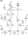
- the talker 110 sends talker advertisement messages 111 in both directions of the ring topology within a ring topology comprising a number of switches 100.
- a first listener 120a and a second listener 120b use accumulated latency as a path selection criterion. For example, due to a better accumulated latency for talker advertisement messages 111 sent in a clockwise direction, the first listener 120a selects a path in the counterclockwise direction to the talker 110 and sends its listener ready messages 121 in this direction.
- the second listener 120b selects a path in the clockwise direction, for example because of a better accumulated latency for talker advertisement messages 111 sent counterclockwise, and sends its listener ready messages 122 in this direction.
- the accumulated latency of the talker advertisement messages 111 in the present exemplary embodiment is the same in both directions within the ring topology. Because of this, the third listener 120c uses a low resource utilization as an additional path selection criterion. For example, clockwise resource utilization may be higher as a result of a data stream set up for video transmission from a camera 130 to an operator control and monitoring station 140 . In this case, the third listener 120c selects the counterclockwise path and sends its Listener Ready messages 123 in this direction.
- the fourth listener 120d simply joins this data stream and sends its listener ready message 124 accordingly in a clockwise direction.
Landscapes
- Engineering & Computer Science (AREA)
- Computer Networks & Wireless Communication (AREA)
- Signal Processing (AREA)
- Small-Scale Networks (AREA)
Abstract
Die Erfindung betrifft ein Verfahren und ein Kommunikationsgerät zur Übermittlung zeitkritischer Daten. Das Kommunikationsgerät dafür ausgestaltet und eingerichtet ist, bei einer Übermittlung von durch erste Kommunikationsgeräte über zumindest zwei zueinander redundante Pfade gesendeten ersten Datagrammen jeweils einen Güteindikator zu ermitteln und in die ersten Datagramme einzufügen. Außerdem reserviert das Kommunikationsgerät auf die ersten Datagramme und auf durch zweite Kommunikationsgeräte zur Reservierung von Ressourcen gesendete zweite Datagramme jeweils bei ausreichender Verfügbarkeit Ressourcen zur Übermittlung von Datenströmen über die redundanten Pfade. Darüber hinaus stellt das Kommunikationsgerät durch die zweiten Kommunikationsgeräte anhand des jeweiligen Güteindikators ausgewählte Pfade zur Übermittlung der Datenströme und nicht ausgewählte Pfade als Reserve-Pfade bereit.The invention relates to a method and a communication device for transmitting time-critical data. The communication device is designed and set up to determine a quality indicator and insert it into the first datagrams when first datagrams are transmitted by first communication devices via at least two mutually redundant paths. In addition, the communication device reserves resources for the transmission of data streams via the redundant paths for the first datagrams and for second datagrams sent by second communication devices for reserving resources, in each case if there is sufficient availability. In addition, the communication device provides paths selected by the second communication devices based on the respective quality indicator for the transmission of the data streams and non-selected paths as reserve paths.
Description
Industrielle Automatisierungssysteme umfassen üblicherweise eine Vielzahl von über ein industrielles Kommunikationsnetz miteinander vernetzten Automatisierungsgeräten und dienen im Rahmen einer Fertigungs- oder Prozessautomatisierung zur Steuerung oder Regelung von Anlagen, Maschinen bzw. Geräten. Aufgrund zeitkritischer Rahmenbedingungen in industriellen Automatisierungssystemen werden zur Kommunikation zwischen Automatisierungsgeräten überwiegend Echtzeit-Kommunikationsprotokolle, wie PROFINET, PROFIBUS, Real-Time-Ethernet oder Time-Sensitive Networking (TSN), verwendet. Insbesondere können Steuerungsdienste bzw. -anwendungen automatisiert und auslastungsabhängig auf aktuell verfügbare Server oder virtuelle Maschinen eines industriellen Automatisierungssystems verteilt werden.Industrial automation systems usually include a large number of automation devices that are networked with one another via an industrial communication network and are used in the context of manufacturing or process automation to control or regulate systems, machines or devices. Due to time-critical framework conditions in industrial automation systems, real-time communication protocols such as PROFINET, PROFIBUS, Real-Time Ethernet or Time-Sensitive Networking (TSN) are predominantly used for communication between automation devices. In particular, control services or applications can be automated and distributed to currently available servers or virtual machines of an industrial automation system depending on the workload.
Unterbrechungen von Kommunikationsverbindungen zwischen Rechnereinheiten eines industriellen Automatisierungssystems oder Automatisierungsgeräten können zu einer unerwünschten oder unnötigen Wiederholung einer Übermittlung einer Dienstanforderung führen. Außerdem können nicht oder nicht vollständig übermittelte Nachrichten beispielsweise einen Übergang oder Verbleib eines industriellen Automatisierungssystems in einen sicheren Betriebszustand verhindern.Interruptions in communication links between computer units in an industrial automation system or automation devices can lead to an unwanted or unnecessary repetition of a transmission of a service request. In addition, messages that are not transmitted or not transmitted in full can, for example, prevent an industrial automation system from transitioning to or remaining in a safe operating state.
In Ethernet-basierten Kommunikationsnetzen können Probleme entstehen, wenn Netzressourcen für eine Übermittlung von Datenströmen oder von Datenrahmen mit Echtzeitanforderungen konkurrierend für eine Übermittlung von Datenrahmen mit großem Nutzdateninhalt ohne spezielle Dienstgüteanforderungen beansprucht werden. Dies kann schließlich dazu führen, dass Datenströme oder Datenrahmen mit Echtzeitanforderungen nicht entsprechend einer angeforderten bzw. benötigten Dienstgüte übermittelt werden.Problems can arise in Ethernet-based communication networks when network resources for transmission of data streams or data frames with real-time requirements compete for transmission of data frames with large user data content without special quality of service requirements be claimed. Ultimately, this can lead to data streams or data frames with real-time requirements not being transmitted in accordance with a requested or required quality of service.
Eine priorisierte Übermittlung von Datenrahmen ist beispielsweise auf Grundlage von virtuellen lokalen Netzen bzw. Virtual Local Area Networks (VLAN) entsprechend Standard IEEE 802.1Q grundsätzlich mittels entsprechender in Datenrahmen eingefügter Tags möglich. Zur synchronisierten und priorisierten Übertragung insbesondere von Audio- und Videodatenströmen (Audio/Video Bridging) über Kommunikationsnetze ist eine Bandbreitenreservierung für einzelne Kommunikationsverbindungen vorgesehen, denen eine höchste Priorität zugeordnet ist. Für eine Übertragung von Audio- und Videodatenströmen benötigte Ressourcen werden dabei in Kommunikationsgeräten wie Switches reserviert. Eine Weiterleitung hochpriorisierter Datenrahmen erfolgt jedoch erst nach einer erfolgreichen Reservierung. Im Rahmen einer Bandbreitenüberwachung wird sichergestellt, dass hinsichtlich tatsächlich genutzter Bandbreite ausreichend reservierte Bandbreite vorliegt. Eine Kommunikationsverbindung, die mehr Bandbreite nutzt als reserviert ist, würde ansonsten zu einer Störung eines gesamten Kommunikationsnetzes führen, im ungünstigsten Fall zu dessen Stillstand aufgrund Überlastung.A prioritized transmission of data frames is possible, for example, on the basis of virtual local networks or virtual local area networks (VLAN) according to the IEEE 802.1Q standard, in principle by means of appropriate tags inserted into data frames. For the synchronized and prioritized transmission of audio and video data streams in particular (audio/video bridging) via communication networks, a bandwidth reservation is provided for individual communication connections that are assigned the highest priority. Resources required for the transmission of audio and video data streams are reserved in communication devices such as switches. However, high-priority data frames are only forwarded after a successful reservation. As part of bandwidth monitoring, it is ensured that there is sufficient reserved bandwidth with regard to the bandwidth actually used. A communication connection that uses more bandwidth than is reserved would otherwise lead to a disruption in an entire communication network, and in the worst case to its standstill due to overload.
Entsprechend
Aus
Um Ausfälle von Übertragungsstrecken oder Kommunikationsgeräten kompensieren zu können, sind Kommunikationsprotokolle, wie Media Redundancy Protocol (MRP), High-availability Seamless Redundancy (HSR), Parallel Redundancy Protocol (PRP) oder IEEE 802.1CB FRER, für hochverfügbare, redundant betreibbare Kommunikationsnetze entwickelt worden. MRP ist im Standard IEC 62439, Clause 2 definiert und ermöglicht eine Kompensation einzelner Verbindungsausfälle in Netzen mit einfacher Ringtopologie durch stoßbehaftete redundante Datenübermittlung (non-seamless redundancy).In order to be able to compensate for failures of transmission links or communication devices, communication protocols such as Media Redundancy Protocol (MRP), High-availability Seamless Redundancy (HSR), Parallel Redundancy Protocol (PRP) or IEEE 802.1CB FRER have been developed for high-availability, redundantly operable communication networks . MRP is defined in the IEC 62439, Clause 2 standard and enables compensation individual connection failures in networks with a simple ring topology due to bursty redundant data transmission (non-seamless redundancy).
Stoßbehaftete Redundanzverfahren sind dadurch gekennzeichnet, dass eine Datenübermittlung erst bei einem Ausfall einer Übertragungsstrecke oder eines Kommunikationsgeräts auf einen verfügbaren redundanten Pfad umgeschaltet wird. Dies ist mit einer Rekonfiguration des Kommunikationsnetzes verbunden, die üblicherweise eine Rekonfigurationszeit von einigen Millisekunden erfordert. Während dieser Rekonfigurationszeit stehen Funktionen des Kommunikationsnetzes eingeschränkt zur Verfügung.Bursty redundancy methods are characterized in that data transmission is only switched to an available redundant path if a transmission link or a communication device fails. This is associated with a reconfiguration of the communication network, which usually requires a reconfiguration time of a few milliseconds. During this reconfiguration time, functions of the communication network are available to a limited extent.
HSR und PRP sind im Standard IEC 62439, Clause 3 definiert und ermöglichen eine stoßfreie redundante Datenübermittlung (seamless redundancy). Entsprechend HSR und PRP wird jeder Datenrahmen von einem sendenden Kommunikationsgerät dupliziert und auf zumindest zwei verschiedenen Pfaden an einen oder mehrere Empfänger gesendet. Redundant empfangene Datenrahmen werden empfängerseitig detektiert und ausgefiltert.HSR and PRP are defined in the IEC 62439, Clause 3 standard and enable seamless, redundant data transmission (seamless redundancy). According to HSR and PRP, each data frame is duplicated by a sending communication device and sent to one or more recipients on at least two different paths. Redundantly received data frames are detected and filtered out at the receiver end.
Stoßfreie Redundanzverfahren erfordern einen hohen Ressourcenaufwand zur Duplikatefilterung, dem in zahlreichen Switchen oder Bridges keine adäquaten Hardware-Ressourcen gegenüberstehen. Entsprechend IEEE 802.1CB (Frame Replication and Elimination for Reliability) sind zur Übermittlung von TSN-Datenströmen lediglich stoßfreie Redundanzverfahren vorgesehen.Bumpless redundancy methods require a high level of resource expenditure for duplicate filtering, which is not matched by adequate hardware resources in numerous switches or bridges. According to IEEE 802.1CB (Frame Replication and Elimination for Reliability), only bumpless redundancy methods are provided for the transmission of TSN data streams.
Der vorliegenden Erfindung liegt die Aufgabe zugrunde, ein Verfahren zur redundanten Übermittlung von Datenströmen mit zeitkritischen Daten zu schaffen, das einerseits geringe Rekonfigurationszeiten ermöglicht und andererseits mit niedrigem Ressourcenaufwand realisierbar ist, sowie eine geeignete Vorrichtung zur Durchführung des Verfahrens anzugeben.The present invention is based on the object of creating a method for the redundant transmission of data streams with time-critical data which, on the one hand, enables short reconfiguration times and, on the other hand, with low Resource expenditure can be realized, as well as specify a suitable device for carrying out the method.
Diese Aufgabe wird erfindungsgemäß durch ein Verfahren mit den in Anspruch 1 angegebenen Merkmalen und durch ein Kommunikationsgerät mit den in Anspruch 14 angegebenen gelöst. Vorteilhafte Weiterbildungen sind in den abhängigen Ansprüchen angegeben.According to the invention, this object is achieved by a method having the features specified in claim 1 and by a communication device having the features specified in claim 14 . Advantageous developments are specified in the dependent claims.
Entsprechend dem erfindungsgemäßen Verfahren zur Übermittlung zeitkritischer Daten innerhalb eines Kommunikationssystems werden ausgewählte Datagramme Datenströmen zugeordnet und von ersten Kommunikationsgeräten zu zweiten Kommunikationsgeräten über dritte Kommunikationsgeräte umfassende Pfade übermittelt. Die ersten Kommunikationsgeräte senden zur Bekanntmachung abonnierbarer Datenströme jeweils einen Datenstrom-Identifikator umfassende erste Datagramme, insbesondere Talker Advertise oder Talker Announce Nachrichten, über zumindest zwei zueinander redundante Pfade und spezifizieren in den ersten Datagrammen Dienstgüteparameter für den jeweiligen Datenstrom. Insbesondere ist den ersten Kommunikationsgeräten jeweils eine Talker-Funktion zugeordnet, während den zweiten Kommunikationsgeräten jeweils eine Listener-Funktion zugeordnet ist. Die Pfade für die Datenströme können beispielsweise mittels Shortest Path Bridging entsprechend IEEE 802.1aq ermittelt werden.According to the method according to the invention for the transmission of time-critical data within a communication system, selected datagrams are assigned to data streams and transmitted from first communication devices to second communication devices via third communication devices including paths. To announce subscribable data streams, the first communication devices send first datagrams, in particular Talker Advertise or Talker Announce messages, each comprising a data stream identifier, via at least two mutually redundant paths and specify quality of service parameters for the respective data stream in the first datagrams. In particular, a talker function is assigned to each of the first communication devices, while a listener function is assigned to each of the second communication devices. The paths for the data streams can be determined, for example, using shortest path bridging in accordance with IEEE 802.1aq.
Vorzugsweise sind die Kommunikationsgeräte über ein Time-sensitive Network, insbesondere entsprechend IEEE 802.1Q, IEEE 802.1AB, IEEE 802.1AS, IEEE 802.1BA und/oder IEEE 802.1CB, miteinander verbunden. Dabei kann eine Weiterleitung der ausgewählten Datagramme mittels Frame Preemption, insbesondere gemäß IEEE 802.1Qbu, Time-Aware Shaper, insbesondere gemäß IEEE 802.1Qbv, Credit-Based Shaper, insbesondere gemäß IEEE 802.1Qav, Burst Limiting Shaper, Peristaltic Shaper und/oder Priority-Based Shaper gesteuert werden.The communication devices are preferably connected to one another via a time-sensitive network, in particular in accordance with IEEE 802.1Q, IEEE 802.1AB, IEEE 802.1AS, IEEE 802.1BA and/or IEEE 802.1CB. The selected datagrams can be forwarded by means of frame preemption, in particular in accordance with IEEE 802.1Qbu, time-aware shaper, in particular in accordance with IEEE 802.1Qbv, credit-based shaper, in particular in accordance with IEEE 802.1Qav, Burst Limiting Shaper, Peristaltic Shaper and/or Priority-Based Shaper can be controlled.
Die dritten Kommunikationsgeräte ermitteln bei einer Übermittlung der ersten Datagramme über die redundanten Pfade erfindungsgemäß jeweils einen Güteindikator und fügen diesen in die ersten Datagramme ein. Die zweiten Kommunikationsgeräte senden zur Reservierung von durch die dritten Kommunikationsgeräte für eine Übermittlung der Datenströme bereitzustellenden Ressourcen jeweils zweite Datagramme, insbesondere Listener Ready, Listener Join oder Listener Attach Nachrichten, und spezifizieren in diesen den jeweiligen Datenstrom-Identifikator. Auf die ersten und zweiten Datagramme reservieren die dritten Kommunikationsgeräte jeweils bei ausreichender Verfügbarkeit Ressourcen zur Übermittlung der Datenströme über die redundanten Pfade. Die durch die Kommunikationsgeräte bereitzustellenden Ressourcen umfassen insbesondere nutzbare Übertragungszeitfenster, Bandbreite, zugesicherte maximale Latenz, Queue-Anzahl, Queue-Cache bzw. Adress-Cache in Switchen oder Bridges. Die zweiten Kommunikationsgeräte wählen anhand des jeweiligen Güteindikators erfindungsgemäß einen der redundanten Pfade zur Übermittlung der Datenströme aus. Dabei werden nicht ausgewählte Pfade durch die dritten Kommunikationsgeräte als Reserve-Pfade bereitstellt.According to the invention, when the first datagrams are transmitted via the redundant paths, the third communication devices each determine a quality indicator and insert this into the first datagrams. To reserve resources to be provided by the third communication devices for transmission of the data streams, the second communication devices each send second datagrams, in particular Listener Ready, Listener Join or Listener Attach messages, and specify the respective data stream identifier in these. In response to the first and second datagrams, the third communication devices reserve resources for the transmission of the data streams via the redundant paths, provided there is sufficient availability. The resources to be made available by the communication devices include, in particular, usable transmission time windows, bandwidth, guaranteed maximum latency, number of queues, queue cache or address cache in switches or bridges. According to the invention, the second communication devices select one of the redundant paths for the transmission of the data streams on the basis of the respective quality indicator. In this case, non-selected paths are made available as reserve paths by the third communication devices.
Dadurch dass genau einer der redundanten Pfade zur Übermittlung des jeweiligen Datenstroms ausgewählt wird, während die nicht ausgewählten Pfade lediglich als Reserve-Pfade bereitgestellt werden, sind im Gegensatz zu stoßfreien Redundanzverfahren empfängerseitig keine Duplikatefilter-Funktionen erforderlich. Somit lässt sich die vorliegende Erfindung mit geringem Ressourcenaufwand in den Kommunikationsgeräten realisieren. Außerdem können Rekonfigurationszeiten minimiert werden, indem auch Ressourcen für die Reserve-Pfade reserviert werden. Damit kann eine Übermittlung eines Datenstroms bei Topologieänderungen mit sehr geringen Verzögerungen vom jeweils ausgewählten Pfad auf einen Reserve-Pfad umgeschaltet werden.Because exactly one of the redundant paths is selected for the transmission of the respective data stream, while the unselected paths are only provided as reserve paths, no duplicate filter functions are required at the receiver end, in contrast to seamless redundancy methods. The present invention can thus be implemented in the communication devices with little outlay on resources. In addition, reconfiguration times can be minimized by reserving resources for the reserve paths will. In this way, a transmission of a data stream can be switched over from the respectively selected path to a reserve path with very little delay in the event of topology changes.
Der Güteindikator kann beispielsweise einen entlang des jeweiligen Pfads ermittelter Latenzwert, eine maximale reservierte Bandbreite für eine ausgewählte Datenstrom-Klasse entlang des jeweiligen Pfads, eine maximale Auslastung von Übertragungsstrecken für eine ausgewählte Datenstrom-Klasse entlang des jeweiligen Pfads bzw. Pfadkosten umfassen. Insbesondere kann der Güteindikator eine Kombination dieser Kriterien umfassen.The quality indicator can include, for example, a latency value determined along the respective path, a maximum reserved bandwidth for a selected data flow class along the respective path, a maximum utilization of transmission links for a selected data flow class along the respective path or path costs. In particular, the quality indicator can include a combination of these criteria.
Vorteilhafterweise wählen die zweiten Kommunikationsgeräte jeweils den Pfad mit dem niedrigsten Latenzwert, mit der niedrigsten maximalen reservierten Bandbreite, mit der niedrigsten maximalen Auslastung bzw. mit den niedrigsten Pfadkosten als zunächst aktiven Pfad aus. Bei einer Unterbrechung entlang eines ausgewählten Pfads wird die Übermittlung des jeweiligen Datenstroms vorzugsweise auf einen Reserve-Pfad umgeschaltet. Grundsätzlich können die Ressourcen zur Übermittlung des jeweiligen Datenstroms über den Reserve-Pfad erst nach der Unterbrechung entlang des ausgewählten Pfads reserviert werden. Dies ermöglicht eine weitere Reduktion des Ressourcenaufwands zur Realisierung der vorliegenden Erfindung.Advantageously, the second communication devices each select the path with the lowest latency value, with the lowest maximum reserved bandwidth, with the lowest maximum utilization or with the lowest path costs as the initially active path. In the event of an interruption along a selected path, the transmission of the respective data stream is preferably switched to a reserve path. In principle, the resources for transmitting the respective data stream via the reserve path can only be reserved after the interruption along the selected path. This enables a further reduction in the resource requirements for realizing the present invention.
Entsprechend einer bevorzugten Ausgestaltung der vorliegenden Erfindung werden die ausgewählten Datagramme von den ersten Kommunikationsgeräten zu den zweiten Kommunikationsgeräten innerhalb vorgegebener periodischer Zeitintervalle übermittelt werden. Dabei werden die vorgegebenen Zeitintervalle an allen Kommunikationsgeräten synchronisiert. Somit ist die vorliegende Erfindung auch zur Übermittlung von Datenströmen für zyklischem Datenverkehr geeignet, insbesondere in industriellen Automatisierungssystemen.According to a preferred embodiment of the present invention, the selected datagrams are transmitted from the first communication devices to the second communication devices within predetermined periodic time intervals. The specified time intervals are synchronized on all communication devices. Thus the The present invention is also suitable for transmitting data streams for cyclic data traffic, particularly in industrial automation systems.
Vorzugsweise überprüft jedes Kommunikationsgerät entlang eines Pfads für einen Datenstrom anhand der Dienstgüteparameter bei einer Reservierungsanfrage jeweils, ob im jeweiligen Kommunikationsgerät ausreichende Ressourcen zur Datenübermittlung unter Einhaltung der spezifizierten Dienstgüteparameter verfügbar sind. Bei ausreichenden Ressourcen ermitteln Konfigurationssteuerungseinheiten der Kommunikationsgeräte entlang eines Pfads für einen Datenstrom jeweils Konfigurationsinformationen und richten das jeweilige Kommunikationsgerät entsprechend den ermittelten Konfigurationsinformationen zur Ressourcen-Bereitstellung für eine Übermittlung der Datenströme ein. Entsprechend einer besonders bevorzugten Ausgestaltung der vorliegenden Erfindung wird bei Verfügbarkeit ausreichender Ressourcen jeweils eine dem spezifizierten Datenstrom-Identifikator zugeordnete Multicast-Adresse an ein anfragendes zweites Kommunikationsgerät übermittelt.Preferably, each communication device along a path for a data stream uses the quality of service parameters to check in the case of a reservation request whether sufficient resources are available in the respective communication device for data transmission while complying with the specified quality of service parameters. If there are sufficient resources, configuration control units of the communication devices determine configuration information along a path for a data stream and set up the respective communication device according to the determined configuration information for resource provision for transmission of the data streams. According to a particularly preferred embodiment of the present invention, if sufficient resources are available, a multicast address assigned to the specified data stream identifier is transmitted to a requesting second communication device.
Das erfindungsgemäße Kommunikationsgerät ist zur Durchführung eines Verfahrens entsprechend vorangehenden Ausführungen vorgesehen und umfasst mehrere Anschlüsse zur Verbindung mit weiteren Kommunikationsgeräten sowie ein Koppelelement, durch das die Anschlüsse schaltbar miteinander verbindbar sind. Das Koppelelement kann insbesondere ein Backplane Switch sein, der mit den Anschlüssen zugeordneten Sende- und Empfangseinheiten verbunden ist. Die Sende- und Empfangseinheiten sind vorzugsweise mittels PHY/MAC-Schaltkreisen realisiert. Darüber hinaus ist das Kommunikationsgerät erfindungsgemäß dafür ausgestaltet und eingerichtet, ausgewählte Datagramme Datenströmen zuzuordnen und von ersten Kommunikationsgeräten zu zweiten Kommunikationsgeräten zu übermitteln. Außerdem ist das Kommunikationsgerät dafür ausgestaltet und eingerichtet, bei einer Übermittlung von durch die ersten Kommunikationsgeräte über zumindest zwei zueinander redundante Pfade gesendeten ersten Datagrammen jeweils einen Güteindikator zu ermitteln und in die ersten Datagramme einzufügen. Dabei umfassen die ersten Datagramme jeweils einen Datenstrom-Identifikator und für den jeweiligen Datenstrom spezifizierte Dienstgüteparameter.The communication device according to the invention is intended for carrying out a method in accordance with the preceding statements and comprises a number of connections for connection to further communication devices and a coupling element, by means of which the connections can be connected to one another in a switchable manner. In particular, the coupling element can be a backplane switch, which is connected to the transmission and reception units assigned to the connections. The transmitting and receiving units are preferably implemented using PHY/MAC circuits. In addition, the communication device is designed and set up according to the invention to assign selected datagrams to data streams and to transmit them from first communication devices to second communication devices. Besides is the communication device is designed and set up to determine a quality indicator and insert it into the first datagrams when first datagrams are transmitted by the first communication devices via at least two mutually redundant paths. The first datagrams each include a data flow identifier and quality of service parameters specified for the respective data flow.
Darüber hinaus ist das Kommunikationsgerät erfindungsgemäß dafür ausgestaltet und eingerichtet, auf die ersten Datagramme und auf durch die zweiten Kommunikationsgeräte zur Reservierung von Ressourcen gesendete zweite Datagramme jeweils bei ausreichender Verfügbarkeit Ressourcen zur Übermittlung der Datenströme über die redundanten Pfade zu reservieren. Dabei umfassen die zweiten Datagramme jeweils einen für den jeweiligen Datenstrom spezifizierten Datenstrom-Identifikator. Schließlich ist das Kommunikationsgerät dafür ausgestaltet und eingerichtet, durch die zweiten Kommunikationsgeräte anhand des jeweiligen Güteindikators ausgewählte Pfade zur Übermittlung der Datenströme und nicht ausgewählte Pfade als Reserve-Pfade bereitzustellen.In addition, the communication device is designed and set up according to the invention to reserve resources for the transmission of the data streams via the redundant paths for the first datagrams and for second datagrams sent by the second communication devices for reserving resources in each case when there is sufficient availability. The second datagrams each include a data flow identifier specified for the respective data flow. Finally, the communication device is designed and set up to provide paths selected by the second communication devices based on the respective quality indicator for the transmission of the data streams and non-selected paths as reserve paths.
Die vorliegende Erfindung wird nachfolgend an einem Ausführungsbeispiel anhand der Zeichnung näher erläutert. Es zeigt
- Figur 1
- ein mehrere Kommunikationsgeräte umfassendes Kommunikationsnetz eines industriellen Automatisierungssystems,
- Figur 2
- eine schematische Darstellung einer Übermittlung eines Datenstroms an mehrere Abonnenten über redundante, umschaltbare Pfade.
- figure 1
- a communication network of an industrial automation system comprising several communication devices,
- figure 2
- a schematic representation of a transmission of a data stream to multiple subscribers via redundant, switchable paths.
Das in
Speicherprogrammierbare Steuerungen 101 umfassen typischerweise jeweils ein Kommunikationsmodul, eine Zentraleinheit sowie zumindest eine Eingabe/Ausgabe-Einheit dar. Eingabe/ Ausgabe-Einheiten können grundsätzlich auch als dezentrale Peripheriemodule ausgestaltet sein, die entfernt von einer speicherprogrammierbaren Steuerung angeordnet sind. Über das Kommunikationsmodul ist eine speicherprogrammierbare Steuerung 101 beispielsweise mit einem Switch oder Router oder zusätzlich mit einem Feldbus verbunden. Die Eingabe/AusgabeEinheit dient einem Austausch von Steuerungs- und Messgrößen zwischen der speicherprogrammierbaren Steuerung 101 und einer durch die speicherprogrammierbare Steuerung 101 gesteuerten Maschine oder Vorrichtung 200. Die Zentraleinheit ist insbesondere für eine Ermittlung geeigneter Steuerungsgrößen aus erfassten Messgrößen vorgesehen. Obige Komponenten der speicherprogrammierbaren Steuerung 101 sind im vorliegenden Ausführungsbeispiel über ein Rückwandbus-System miteinander verbunden.
Eine Bedien- und Beobachtungsstation 102 dient zur Visualisierung von Prozessdaten bzw. Mess- und Steuerungsgrößen, die durch speicherprogrammierbare Steuerungen, Eingabe/Ausgabe-Einheiten oder Sensoren verarbeitet bzw. erfasst werden. Insbesondere wird eine Bedien- und Beobachtungsstation 102 zur Anzeige von Werten eines Regelungskreises und zur Veränderung von Regelungsparametern verwendet. Bedien- und Beobachtungsstationen 102 umfassen zumindest eine graphische Benutzerschnittstelle, ein Eingabegerät, eine Prozessoreinheit und ein Kommunikationsmodul.An operating and
Mittels erster Kommunikationsgeräte 101, die als an Quell-Netzknoten angeschlossene Automatisierungsgeräte ausgestaltet sind und eine Talker-Funktion haben, werden Informationen bzw. Dienste über Multicast-Datenströme zur Nutzung an zweiten Kommunikationsgeräten 102 bereitgestellt, die als an Ziel-Netzknoten angeschlossene Automatisierungsgeräte ausgestaltet sind und eine Listener-Funktion haben. Einem Automatisierungsgerät kann gleichzeitig sowohl eine Talker-Funktion als auch eine Listener-Funktion haben, beispielsweise wenn es einerseits Automatisierungsdienste bereitstellt und andererseits Automatisierungsdienste anderer Geräte nutzt.
Im vorliegenden Ausführungsbeispiel hat die speicherprogrammierbare Steuerung 101 eine Talker-Funktion, während die Bedien- und Beobachtungsstation 102 eine Listener-Funktion aufweist und insbesondere durch die speicherprogrammierbare Steuerung 101 bereitgestellte Informationen empfängt. Grundsätzlich könnte die Bedien- und Beobachtungsstation 102 von der speicherprogrammierbaren Steuerung 101 empfangene Informationen analysieren und hieraus Steuerungsparameter für die speicherprogrammierbare Steuerung 101 vorgeben. Somit würden sowohl die speicherprogrammierbare Steuerung 101 als auch die Bedien- und Beobachtungsstation beide Funktionen wahrnehmen.In the present exemplary embodiment, the
Im Sinn einer vereinfachten Darstellung wird nachfolgend davon ausgegangen, dass beide Geräte jeweils nur eine zugeordnete Funktion aufweisen.For the sake of a simplified representation, it is assumed below that both devices each have only one assigned function.
Im vorliegenden Ausführungsbeispiel werden ausgewählte Datagramme 300 Datenströmen zugeordnet und von ersten Kommunikationsgeräten 101 zu zweiten Kommunikationsgeräten 102 über dritte Kommunikationsgeräte 103 umfassende Pfade übermittelt. Vorzugsweise werden die ausgewählten Datagramme 300 von den ersten Kommunikationsgeräten 101 zu den zweiten Kommunikationsgeräten 102 innerhalb vorgegebener periodischer Zeitintervalle übermittelt, die an allen Kommunikationsgeräten synchronisiert werden. Eine Weiterleitung der ausgewählten Datagramme 300 kann insbesondere mittels Frame Preemption gemäß IEEE 802.1Qbu, Time-Aware Shaper gemäß IEEE 802.1Qbv, Credit-Based Shaper gemäß IEEE 802.1Qav, Burst Limiting Shaper, Peristaltic Shaper bzw. Priority-Based Shaper gesteuert werden.In the present exemplary embodiment, selected
Zur Bekanntmachung abonnierbarer Datenströme senden die ersten Kommunikationsgeräte 101 jeweils einen Datenstrom-Identifikator umfassende erste Datagramme 301, insbesondere Talker Advertise oder Talker Announce Nachrichten, über zumindest zwei zueinander redundante Pfade 310, 320 senden und spezifizieren in den ersten Datagrammen 301 Dienstgüteparameter für den jeweiligen Datenstrom. Bei einer Übermittlung der ersten Datagramme 301 über die redundanten Pfade 310, 320 ermitteln die dritten Kommunikationsgeräte 103 jeweils einen Güteindikator 311 und fügen diesen jeweils in die ersten Datagramme 301 ein. Der Güteindikator 311 kann beispielsweise einen entlang des jeweiligen Pfads 310, 320 ermittelten Latenzwert, eine maximale reservierte Bandbreite für eine ausgewählte Datenstrom-Klasse entlang des jeweiligen Pfads 310, 320, eine maximale Auslastung von Übertragungsstrecken für eine ausgewählte Datenstrom-Klasse entlang des jeweiligen Pfads 310, 320, Pfadkosten oder eine Kombination dieser Kriterien umfassen.To announce data streams that can be subscribed to, the
Die zweiten Kommunikationsgeräte 102 senden zur Reservierung von durch die dritten Kommunikationsgeräte 103 für eine Übermittlung der Datenströme bereitzustellenden Ressourcen jeweils zweite Datagramme 302, insbesondere Listener Ready, Listener Join oder Listener Attach Nachrichten, und spezifizieren in diesen den jeweiligen Datenstrom-Identifikator. Die dritten Kommunikationsgeräte 103 reservieren auf die ersten und zweiten Datagramme 301, 302 - jeweils bei ausreichender Verfügbarkeit - Ressourcen zur Übermittlung der Datenströme über die redundanten Pfade 310, 320. Die durch die Kommunikationsgeräte 101-103 bereitzustellenden Ressourcen umfassen beispielsweise nutzbare Übertragungszeitfenster, Bandbreite, zugesicherte maximale Latenz, Queue-Anzahl, Queue-Cache bzw. Adress-Cache in Switchen oder Bridges.To reserve resources to be provided by the
Die zweiten Kommunikationsgeräte 102 wählen anhand des jeweiligen Güteindikators 311 einen der redundanten Pfade 310, 320 zur Übermittlung der Datenströme aus. Dabei werden nicht ausgewählte Pfade durch die dritten Kommunikationsgeräte 103 als Reserve-Pfade bereitstellt. Im vorliegenden Ausführungsbeispiel wählen die zweiten Kommunikationsgeräte 102 jeweils den Pfad 310, 320 mit dem niedrigsten Latenzwert, mit der niedrigsten maximalen reservierten Bandbreite, mit der niedrigsten maximalen Auslastung bzw. mit den niedrigsten Pfadkosten oder mit einer optimalen Kombination dieser Kriterien aus. Insbesondere wird die Übermittlung des jeweiligen Datenstroms bei einer Unterbrechung entlang eines ausgewählten Pfads 310, 320 auf einen Reserve-Pfad umgeschaltet. Hierzu müssen die Ressourcen zur Übermittlung des jeweiligen Datenstroms über den Reserve-Pfad nicht unbedingt prophylaktisch reserviert werden. Vielmehr ist es grundsätzlich ausreichend, wenn die Ressourcen zur Übermittlung des jeweiligen Datenstroms über den Reserve-Pfad erst nach der Unterbrechung entlang des ausgewählten Pfads reserviert werden.The
Entsprechend einem dezentralen Ansatz zur Reservierung von Ressourcen zur Übermittlung von Datenströmen überprüft jedes Kommunikationsgerät 101-103 entlang eines Pfads 310, 320 für einen Datenstrom anhand der Dienstgüteparameter bei einer Reservierungsanfrage jeweils, ob im jeweiligen Kommunikationsgerät 101-103 ausreichende Ressourcen zur Datenübermittlung unter Einhaltung der spezifizierten Dienstgüteparameter verfügbar sind. Eine zentrale Instanz zur Ressourcenverwaltung oder Pfadermittlung ist mit dem dezentralen Ansatz zur Ressourcen-Reservierung für Datenströme nicht erforderlich. Die Pfade 310, 320 für die Datenströme können beispielsweise mittels Shortest Path Bridging entsprechend IEEE 802.1aq ermittelt werden.According to a decentralized approach to reserving resources for the transmission of data streams, each communication device 101-103 along a
Bei Verfügbarkeit ausreichender Ressourcen wird jeweils eine dem spezifizierten Datenstrom-Identifikator zugeordnete Multicast-Adresse an ein anfragendes zweites Kommunikationsgerät 102 übermittelt. Außerdem ermitteln Konfigurationssteuerungseinheiten der Kommunikationsgeräte 101-103 entlang eines Pfads 310, 320 für einen Datenstrom bei ausreichenden Ressourcen jeweils Konfigurationsinformationen und richten das jeweilige Kommunikationsgerät 101-103 entsprechend den ermittelten Konfigurationsinformationen zur Ressourcen-Bereitstellung für eine Übermittlung der Datenströme ein.If sufficient resources are available, a multicast address assigned to the specified data stream identifier is transmitted to a requesting
Entsprechend der Darstellung in
Für einen dritten Listener 120c ist die Accumulated Latency der Talker Advertisment Nachtrichten 111 im vorliegenden Ausführungsbeispiel in beiden Richtungen innerhalb der Ringtopologie gleich. Aufgrund dessen verwendet der dritte Listener 120c eine geringe Ressourcenauslastung als zusätzliches Pfadauswahlkriterium. Beispielsweise kann die Ressourcenauslastung in Uhrzeigerrichtung infolge eines für eine Videoübertragung von einer Kamera 130 zu einer Bedien- und Beobachtungsstation 140 eingerichteten Datenstroms höher sein. In diesem Fall wählt der dritte Listener 120c den Pfad in Gegenuhrzeigerrichtung aus und versendet seine Listener Ready Nachtrichten 123 in diese Richtung.For a
Ist bereits ein Datenstrom vom Talker 110 in Gegenuhrzeigerrichtung zum dritten Listener 120c über einen Switch 100 aufgebaut, an den ein vierter Listener 120d angeschlossen ist, so schließt sich der vierte Listener 120d diesem Datenstrom einfach an und versendet seine Listener Ready Nachricht 124 dementsprechend in Uhrzeigerrichtung.If a data stream has already been established from the
Claims (14)
bei dem der Güteindikator einen entlang des jeweiligen Pfads ermittelter Latenzwert, eine maximale reservierte Bandbreite für eine ausgewählte Datenstrom-Klasse entlang des jeweiligen Pfads, eine maximale Auslastung von Übertragungsstrecken für eine ausgewählte Datenstrom-Klasse entlang des jeweiligen Pfads und/oder Pfadkosten umfasst.Method according to claim 1,
in which the quality indicator includes a latency value determined along the respective path, a maximum reserved bandwidth for a selected data flow class along the respective path, a maximum utilization of transmission links for a selected data flow class along the respective path and/or path costs.
bei dem die zweiten Kommunikationsgeräte jeweils den Pfad mit dem niedrigsten Latenzwert, mit der niedrigsten maximalen reservierten Bandbreite, mit der niedrigsten maximalen Auslastung und/oder mit den niedrigsten Pfadkosten auswählen.Method according to claim 2,
in which the second communication devices each select the path with the lowest latency value, with the lowest maximum reserved bandwidth, with the lowest maximum load and/or with the lowest path costs.
bei dem bei einer Unterbrechung entlang eines ausgewählten Pfads die Übermittlung des jeweiligen Datenstroms auf einen Reserve-Pfad umgeschaltet wird.Method according to one of claims 1 to 3,
in which, in the event of an interruption along a selected path, the transmission of the respective data stream is switched to a reserve path.
bei dem die Ressourcen zur Übermittlung des jeweiligen Datenstroms über den Reserve-Pfad erst nach der Unterbrechung entlang des ausgewählten Pfads reserviert werden.Method according to claim 4,
in which the resources for the transmission of the respective data stream via the reserve path are only reserved after the interruption along the selected path.
bei dem die ausgewählten Datagramme (300) von den ersten Kommunikationsgeräten (101) zu den zweiten Kommunikationsgeräten (102) innerhalb vorgegebener periodischer Zeitintervalle übermittelt werden und bei dem die vorgegebenen Zeitintervalle an allen Kommunikationsgeräten (101-103) synchronisiert werden.Method according to one of claims 1 to 5,
in which the selected datagrams (300) are transmitted from the first communication devices (101) to the second communication devices (102) within predetermined periodic time intervals and in which the predetermined time intervals are synchronized at all communication devices (101-103).
bei dem jedes Kommunikationsgerät (101-103) entlang eines Pfads (310, 320) für einen Datenstrom anhand der Dienstgüteparameter bei einer Reservierungsanfrage jeweils überprüft, ob im jeweiligen Kommunikationsgerät ausreichende Ressourcen zur Datenübermittlung unter Einhaltung der spezifizierten Dienstgüteparameter verfügbar sind und bei dem Konfigurationssteuerungseinheiten der Kommunikationsgeräte entlang eines Pfads für einen Datenstrom bei ausreichenden Ressourcen jeweils Konfigurationsinformationen ermitteln und das jeweilige Kommunikationsgerät entsprechend den ermittelten Konfigurationsinformationen zur Ressourcen-Bereitstellung für eine Übermittlung der Datenströme einrichten.Method according to one of claims 1 to 6,
in which each communication device (101-103) along a path (310, 320) for a data stream uses the quality of service parameters in a reservation request to check whether sufficient resources for data transmission are available in the respective communication device while complying with the specified quality of service parameters and in the configuration control units of the communication devices determine configuration information along a path for a data stream given sufficient resources and set up the respective communication device according to the determined configuration information for resource provision for transmission of the data streams.
bei dem die durch die Kommunikationsgeräte bereitzustellenden Ressourcen nutzbare Übertragungszeitfenster, Bandbreite, zugesicherte maximale Latenz, Queue-Anzahl, Queue-Cache und/oder Adress-Cache in Switchen oder Bridges umfassen.Method according to one of claims 1 to 7,
in which the resources to be made available by the communication devices include usable transmission time windows, bandwidth, guaranteed maximum latency, queue number, queue cache and/or address cache in switches or bridges.
bei dem bei Verfügbarkeit ausreichender Ressourcen jeweils eine dem spezifizierten Datenstrom-Identifikator zugeordnete Multicast-Adresse an ein anfragendes zweites Kommunikationsgerät übermittelt wird.Method according to one of claims 1 to 8,
in which, if sufficient resources are available, a multicast address assigned to the specified data flow identifier is transmitted to a requesting second communication device.
bei dem die Kommunikationsgeräte über ein Time-sensitive Network, insbesondere entsprechend IEEE 802.1Q, IEEE 802.1AB, IEEE 802.1AS, IEEE 802.1BA und/oder IEEE 802.1CB, miteinander verbunden sind.Method according to one of claims 1 to 9,
in which the communication devices are connected to one another via a time-sensitive network, in particular according to IEEE 802.1Q, IEEE 802.1AB, IEEE 802.1AS, IEEE 802.1BA and/or IEEE 802.1CB.
bei dem eine Weiterleitung der ausgewählten Datagramme mittels Frame Preemption, insbesondere gemäß IEEE 802.1Qbu, Time-Aware Shaper, insbesondere gemäß IEEE 802.1Qbv, Credit-Based Shaper, insbesondere gemäß IEEE 802.1Qav, Burst Limiting Shaper, Peristaltic Shaper und/oder Priority-Based Shaper gesteuert wird.Method according to claim 10,
in which the selected datagrams are forwarded by means of frame preemption, in particular in accordance with IEEE 802.1Qbu, time-aware shaper, in particular in accordance with IEEE 802.1Qbv, credit-based shaper, in particular in accordance with IEEE 802.1Qav, burst limiting shaper, peristaltic shaper and/or priority Based Shaper is controlled.
bei dem den ersten Kommunikationsgeräten jeweils eine Talker-Funktion zugeordnet ist und bei dem den zweiten Kommunikationsgeräten jeweils eine Listener-Funktion zugeordnet ist.Method according to one of claims 1 to 11,
in which a talker function is assigned to each of the first communication devices and in which a listener function is assigned to each of the second communication devices.
bei dem die Pfade für die Datenströme mittels Shortest Path Bridging entsprechend IEEE 802.1aq ermittelt werden.Method according to one of claims 1 to 12,
where the paths for the data streams are determined using shortest path bridging in accordance with IEEE 802.1aq.
Priority Applications (1)
| Application Number | Priority Date | Filing Date | Title |
|---|---|---|---|
| EP20198954.8A EP3975488A1 (en) | 2020-09-29 | 2020-09-29 | Method and communication device for transmitting time-critical data |
Applications Claiming Priority (1)
| Application Number | Priority Date | Filing Date | Title |
|---|---|---|---|
| EP20198954.8A EP3975488A1 (en) | 2020-09-29 | 2020-09-29 | Method and communication device for transmitting time-critical data |
Publications (1)
| Publication Number | Publication Date |
|---|---|
| EP3975488A1 true EP3975488A1 (en) | 2022-03-30 |
Family
ID=72670570
Family Applications (1)
| Application Number | Title | Priority Date | Filing Date |
|---|---|---|---|
| EP20198954.8A Withdrawn EP3975488A1 (en) | 2020-09-29 | 2020-09-29 | Method and communication device for transmitting time-critical data |
Country Status (1)
| Country | Link |
|---|---|
| EP (1) | EP3975488A1 (en) |
Citations (4)
| Publication number | Priority date | Publication date | Assignee | Title |
|---|---|---|---|---|
| EP2501078A1 (en) * | 2011-03-14 | 2012-09-19 | Broadcom Corporation | Stream path selection within convergent networks |
| US20120314597A1 (en) * | 2011-06-08 | 2012-12-13 | Harkirat Singh | Enhanced stream reservation protocol for audio video networks |
| EP3038325B1 (en) | 2014-12-22 | 2019-12-11 | Siemens Aktiengesellschaft | Method for transmitting data in a communications network of an industrial automation system and coupling communication device |
| EP3674824A1 (en) | 2018-12-28 | 2020-07-01 | Siemens Aktiengesellschaft | Method for operating a communication system for transferring time-critical data and communication device |
-
2020
- 2020-09-29 EP EP20198954.8A patent/EP3975488A1/en not_active Withdrawn
Patent Citations (4)
| Publication number | Priority date | Publication date | Assignee | Title |
|---|---|---|---|---|
| EP2501078A1 (en) * | 2011-03-14 | 2012-09-19 | Broadcom Corporation | Stream path selection within convergent networks |
| US20120314597A1 (en) * | 2011-06-08 | 2012-12-13 | Harkirat Singh | Enhanced stream reservation protocol for audio video networks |
| EP3038325B1 (en) | 2014-12-22 | 2019-12-11 | Siemens Aktiengesellschaft | Method for transmitting data in a communications network of an industrial automation system and coupling communication device |
| EP3674824A1 (en) | 2018-12-28 | 2020-07-01 | Siemens Aktiengesellschaft | Method for operating a communication system for transferring time-critical data and communication device |
Non-Patent Citations (3)
| Title |
|---|
| ANONYMOUS: "Time-Sensitive Networking - Wikipedia -Version vom 17. Juni 2020", 17 June 2020 (2020-06-17), XP055781066, Retrieved from the Internet <URL:https://de.wikipedia.org/w/index.php?title=Time-Sensitive_Networking&oldid=201060322> [retrieved on 20210302] * |
| FENG CHEN (CHEN FENG@SIEMENS COM) CONTRIBUTORS: FRANZ-JOSEF GOETZ ET AL: "Resource Allocation Protocol (RAP) 1 based on LRP for Distributed 2 Configuration of Time-Sensitive Streams 3", vol. 802, no. v02, 7 November 2017 (2017-11-07), pages 1 - 21, XP068120402, Retrieved from the Internet <URL:grouper.ieee.org/groups/802/1/files/public/docs2017/tsn-chen-RAP-whitepaper-1117-v02.pdf> [retrieved on 20171107] * |
| MARCEL KIESSLING ET AL: "How to continue with Qcc ; cc-kiessling-Next-Steps-0715-v01", IEEE DRAFT; CC-KIESSLING-NEXT-STEPS-0715-V01, IEEE-SA, PISCATAWAY, NJ USA, vol. 802, no. v01, 14 July 2015 (2015-07-14), pages 1 - 17, XP068101265 * |
Similar Documents
| Publication | Publication Date | Title |
|---|---|---|
| EP3038325B1 (en) | Method for transmitting data in a communications network of an industrial automation system and coupling communication device | |
| EP3674824B1 (en) | Method for operating a communication system for transferring time-critical data and communication device | |
| EP3664465B1 (en) | Method for operating a communication system for transferring time-critical data, and communication control device | |
| EP3035606A1 (en) | Method for transmitting data in a communication network comprising at least 2 virtual local networks and communication device for an industrial automation system | |
| WO2004039012A1 (en) | Methods, interface unit and nodes for using in parallel a communication network for real-time applications and non real-time applications | |
| EP2661023A1 (en) | Communication device for a redundant industrial communication network and method for operating a communication device | |
| DE102017125086A1 (en) | Data transmission method and communication network | |
| EP3618384B1 (en) | Method for simulating a processing of reservation requests for multi cast data flows in communication networks and simulation system | |
| WO2021170343A1 (en) | Method for synchronizing control applications by means of a communication network for transferring time-critical data, network infrastructure device and communication terminal | |
| EP2670078A1 (en) | Communication device for a redundant industrial communication network and method for operating a communication device | |
| EP3226484A1 (en) | Method for transmitting data in a communications network of an industrial automation system and communication device | |
| EP3629548B1 (en) | Method for transmitting data within an industrial communication network and communication device | |
| WO2023126127A1 (en) | Method and system for providing time-critical control applications | |
| EP3975488A1 (en) | Method and communication device for transmitting time-critical data | |
| EP1599980A1 (en) | Synchronous multi-cluster network architecture | |
| EP3629550A1 (en) | Method for transmitting data within an industrial communication system and coupling communication device | |
| EP3917089A1 (en) | Method for operating a communication system for transferring time-critical data and switch | |
| EP3715983A1 (en) | Method for providing control applications over a communications network for transmitting time-critical data and coordination device | |
| EP3905602A1 (en) | Method for operating a communication system for transferring time-critical data and control device | |
| EP3846395A1 (en) | Method for redundant transmission of data streams in a communication network, network infrastructure device and communication terminal | |
| EP3758310A1 (en) | Method for data communication, network control device, network, computer program and computer readable medium | |
| EP3716519A1 (en) | Method for transmitting time-critical data within a communication network and communication device | |
| EP3896918A1 (en) | Method for operating a communication system for transferring time-critical data, domain control device and communication control device | |
| EP2854345A1 (en) | Method and coupling communication device for message delivery in a redundantly operable industrial communication network | |
| EP4156644A1 (en) | Method for transmitting time-critical data within a communication system and communication device |
Legal Events
| Date | Code | Title | Description |
|---|---|---|---|
| PUAI | Public reference made under article 153(3) epc to a published international application that has entered the european phase |
Free format text: ORIGINAL CODE: 0009012 |
|
| STAA | Information on the status of an ep patent application or granted ep patent |
Free format text: STATUS: THE APPLICATION HAS BEEN PUBLISHED |
|
| AK | Designated contracting states |
Kind code of ref document: A1 Designated state(s): AL AT BE BG CH CY CZ DE DK EE ES FI FR GB GR HR HU IE IS IT LI LT LU LV MC MK MT NL NO PL PT RO RS SE SI SK SM TR |
|
| STAA | Information on the status of an ep patent application or granted ep patent |
Free format text: STATUS: THE APPLICATION IS DEEMED TO BE WITHDRAWN |
|
| 18D | Application deemed to be withdrawn |
Effective date: 20221001 |