EP3968722A1 - Verbesserte ratensignalisierung in drahtlosen netzwerken mit relaisfunktion - Google Patents
Verbesserte ratensignalisierung in drahtlosen netzwerken mit relaisfunktion Download PDFInfo
- Publication number
- EP3968722A1 EP3968722A1 EP20196334.5A EP20196334A EP3968722A1 EP 3968722 A1 EP3968722 A1 EP 3968722A1 EP 20196334 A EP20196334 A EP 20196334A EP 3968722 A1 EP3968722 A1 EP 3968722A1
- Authority
- EP
- European Patent Office
- Prior art keywords
- data rate
- communication device
- logical channel
- relay
- downstream
- Prior art date
- Legal status (The legal status is an assumption and is not a legal conclusion. Google has not performed a legal analysis and makes no representation as to the accuracy of the status listed.)
- Withdrawn
Links
Images


Classifications
-
- H—ELECTRICITY
- H04—ELECTRIC COMMUNICATION TECHNIQUE
- H04W—WIRELESS COMMUNICATION NETWORKS
- H04W76/00—Connection management
- H04W76/10—Connection setup
- H04W76/14—Direct-mode setup
-
- H—ELECTRICITY
- H04—ELECTRIC COMMUNICATION TECHNIQUE
- H04B—TRANSMISSION
- H04B7/00—Radio transmission systems, i.e. using radiation field
- H04B7/14—Relay systems
- H04B7/15—Active relay systems
- H04B7/155—Ground-based stations
- H04B7/15528—Control of operation parameters of a relay station to exploit the physical medium
-
- H—ELECTRICITY
- H04—ELECTRIC COMMUNICATION TECHNIQUE
- H04W—WIRELESS COMMUNICATION NETWORKS
- H04W28/00—Network traffic management; Network resource management
- H04W28/16—Central resource management; Negotiation of resources or communication parameters, e.g. negotiating bandwidth or QoS [Quality of Service]
- H04W28/18—Negotiating wireless communication parameters
- H04W28/22—Negotiating communication rate
-
- H—ELECTRICITY
- H04—ELECTRIC COMMUNICATION TECHNIQUE
- H04W—WIRELESS COMMUNICATION NETWORKS
- H04W88/00—Devices specially adapted for wireless communication networks, e.g. terminals, base stations or access point devices
- H04W88/02—Terminal devices
- H04W88/04—Terminal devices adapted for relaying to or from another terminal or user
Definitions
- the invention relates to resource scheduling in wireless networks with relay function, such as - but not limited to - cellular networks with indirect network connections for remote communication devices (e.g. terminal devices such as user equipments (UEs)) which are out of network coverage.
- remote communication devices e.g. terminal devices such as user equipments (UEs)
- network access devices such as base stations, Node Bs (eNBs, eNodeBs, gNBs, gNodeBs, ng-eNBs, etc.), access points or the like
- wireless communication devices e.g. terminal devices such as mobile stations or UEs
- the access devices are connected within a network allowing communication links to be made between the wireless communication devices and other devices.
- the communication links are between wireless communication devices that are close to each other. In these situations, it may be desirable to have a direct communication link between two wireless communication devices rather than communicating through an access device.
- D2D device-to-device
- P2P peer-to-peer
- the communication resources e.g., time-frequency blocks
- the communication resources used for D2D or P2P communication can be a subset of the communication resources used by the communication system for communication between wireless communication devices and access devices or they can be a different set of communication resources (e.g. unlicensed band or millimeter wave band).
- An in-coverage (InC) communication device is a communication device that is within the service area of an access device and is capable of communication with the access device.
- An out-of-coverage (OoC) communication device is typically a communication device that is not within a service area of any access device or that is in the service area of an access device but the access device does not allow access (e.g. because it is a non-public network (NPN) access device).
- An OoC communication device may use an indirect network connection to an access device. It is noted that a communication device can also be an OoC communication device without having any connectivity.
- Resource scheduling may be based on an intricate interplay of multiple scheduling mechanisms and protocols that work alongside each other.
- a scheduler (which may be located at an access device) is expected to take care for a good agreement between resource allocations and recommended bit rate values that it sends to communication devices.
- resources are typically scheduled at a very fine-grained level, i.e. per frame/subframe or even smaller resource units.
- the scheduling is typically defined in terms of quality-of-service (QoS) profiles, priorities, etc.
- QoS quality-of-service
- 3GPP has defined a concept called Recommended Bitrate at the MAC layer (see 3GPP specification TS 38.321).
- This rate has a default averaging window of two seconds and is provided to each UE connected to the access device, and is meant for a specific logical channel.
- the use of this MAC mechanism allows the access device to indicate in a fairly dynamic manner (e.g. not to generate too much data to be transferred), or shift the balance between UEs or between certain logical channels (e.g. because another UE or another channel gets temporarily a higher priority to transmit or receive data). This in turn will have to lead to adhering to a higher layer QoS profile, e.g., to guarantee a certain bitrate for a longer period of time for several UEs.
- the physical layer scheduler needs to take the MAC recommended bit rate into account. For example, a scheduler could allocate a persistent schedule to a specific communication device which means this communication device is granted periodically recurring resources, that enable it to send data at a bit rate of approximately the value recommended to it.
- CN core network
- RAN radio access network
- relay communication devices For good system operation, control mechanisms on both RAN and CN are needed as each has their unique requirements.
- a remote communication device is a communication device that is indirectly connected to a core network via one or more relay functions.
- a problem is that the RAN mechanisms for recommending bit or data rates do not work anymore for indirectly connected communication devices. This means that these communication devices cannot query an access device for a bit rate recommendation and cannot receive a bit rate recommendation from the access device.
- an indirectly connected communication device has no information about what bit rate it could expect from the access device for a particular logical channel, the access device has no information about what bit rate a particular indirectly connected communication device would like to use for a particular logical channel, the access device has no way to influence an indirectly connected communication device that is a data source to go to a lower (or higher) bit rate, and/or the indirectly connected communication device has no direct way to influence the access device to obtain a higher bit rate in case it needs that and to signal which rate would be desired.
- an apparatus for controlling scheduling of communication resources to communication devices at a relay communication device in a wireless network, wherein the apparatus is configured to:
- a method of controlling scheduling of communication resources to communication devices in a wireless network comprises:
- a relay communication device for a wireless network which comprises an apparatus of the first aspect.
- a wireless communication system comprising a relay communication device of the third aspect and an access device, wherein the access device is configured to receive from the relay communication device an aggregate desired data rate for a logical channel, and to determine based on an identity of the logical channel to which downstream communication devices the aggregate desired data rate applies.
- a computer program product which comprises code means for producing the steps of the above method of the second aspect when run on a computer device.
- the new recommendation and/or limit may be an aggregate recommendation and/or limit for the downstream communication device and all its downstream (e.g., child) communication devices. Assigning a logical channel to one or more downstream devices by the relay communication device can be achieved by one or more of the following procedures:
- Determining a new data rate recommendation and/or limit may involve the creation of a new message, the new message including a new data rate and/or limit, and/or including a different logical channel identity than the logical channel identity of the logical channel for which the (aggregate) data rate recommendation was received from an access device or upstream relay communication device, and/or including a different destination than the message received from the access device or upstream relay communication device containing the (aggregate) data rate recommendation.
- the new data rate recommendation and/or limit may be determined to be less than or equal to the aggregate data rate recommendation and/or limit. This allows to schedule a portion of the aggregate data rate recommendation and/or limit to the relay communication device itself. It also allows, for example, to distribute a received aggregate recommendation between multiple downstream communication devices without keeping anything for the relay communication device itself.
- the aggregate data rate recommendation and/or limit may comprise indicator data that indicates whether the aggregate recommendation and/or limit applies to an upstream data flow or a downstream data flow.
- scheduling can be separated for upstream and downstream, which leads to a more efficient schedule for both.
- the resource scheduling by the access device can be made more efficient and more fine-tuned with separate data flow recommendations and/or limits for upstream and downstream.
- a request for an aggregate desired data rate for a logical channel may be sent to the access device or the upstream relay communication device of the relay communication device.
- data rate requests from downstream remote communication devices can be collected at the relay communication device and signaled to the access device or the upstream relay (parent) communication device.
- the request for an aggregate desired data rate for a logical channel may be triggered by and at least partly based on at least one request for a desired data rate received from one of the one or more downstream communication devices. This measure allows to provide a trigger mechanism for aggregate desired data rate request, which can be based on individual data rate requests of remote communication devices.
- a request for a desired data rate for a logical channel may be received at the relay communication device from one of the one or more downstream communication devices, wherein a data rate recommendation and/or limit for the logical channel may be determined at the relay communication device based on the received request, and the determined data rate recommendation and/or limit may be used by the relay communication device to respond to the request.
- the relay communication device may directly respond to desired data rate requests from remote communication devices.
- the relay communication device may be configured to look up in an internal table a corresponding downstream communication device and/or an identity of a second logical channel for which to send a new data rate recommendation and/or limit to the downstream communication device in response to a data rate recommendation and/or limit received from the access device or the upstream relay communication device of the relay communication device and indicating an identity of a first logical channel, or the relay communication device may be configured to look up in the internal table an identity of a second logical channel for which to send a new request for a desired data rate to the access device or an upstream relay communication device of the relay communication device in response to a request for a desired data rate received from one of the one or more downstream communication devices and indicating an identity of a first logical channel.
- logical channel mapping can be applied at the relay communication device in upstream and/or downstream direction to identify target devices for signaling recommendations, limits or desired data rates.
- the relay communication device may be configured to create an additional logical channel on a wireless link with the access device or an upstream relay (e.g. its parent) communication device when it determines that a new logical channel has been created for a communication link with one of the one or more downstream communication devices.
- This measure ensures that channel mapping options are provided for all available logical channels.
- a child communication device may create a new logical channel and in response the parent relay communication device adds a new logical channel on the upstream link.
- the new logical channel may be created towards a first parent communication device while the aggregate recommendations are received from a second parent communication device.
- This can be achieved e.g. by the 3GPP Dual Connectivity mode (cf. 3GPP specifications TS 23.504, TS 38.300 and TS 37.340), which is a mode of operation where a multiple receiver (Rx) / transmitter (Tx) capable UE in RRC Connected mode can be configured to utilize the radio resource of two distinct schedulers located in two access devices, namely Master gNB and Secondary gNB.
- logical channel identities e.g. for a multi-hop relay topology
- may be centrally assigned e.g.
- mapping can be provided to improve signalling efficiency.
- This mapping (or parts thereof) may also be transmitted to an upstream access device or relay communication device, which allows the upstream access device or relay communication device to identify each downstream logical channel individually. Possibly, this mapping may be sent together with or the mapping may be extended with a desired (aggregate) recommended data rate or a recommended data rate being used for each logical channel identity as further input for the upstream access device or relay communication device.
- the internal table may be configured to map an identity of a logical channel between the relay communication device and the access device or the upstream relay (e.g. its parent) communication device to a plurality of identities of logical channels between the relay communication device and the one or more downstream communication devices.
- a one-to-many channel mapping can be provided to improve signaling efficiency.
- a one-to-many mapping may be provided, that maps each logical channel identity to an identifier of the communication device that created the logical channel identity or to a set of identifiers of communication devices that are involved in the logical channel identified by the logical channel identity.
- This mapping (or parts thereof) may also be transmitted to an upstream access device or relay communication device, which allows the upstream access device or relay communication device to identify each downstream logical channel individually. Possibly, this mapping may be sent together with or the mapping may be extended with a desired (aggregate) recommended data rate or a recommended data rate being used for each logical channel identity as further input for the upstream access device or relay communication device.
- the data rate recommendation and/or limit may be transmitted using at least one of Medium Access Control protocol, Radio Link Control protocol, Packet Data Convergence Protocol, Radio Resource Control protocol, and Service Data Adaptation Protocol.
- Medium Access Control protocol Radio Link Control protocol
- Packet Data Convergence Protocol Packet Data Convergence Protocol
- Radio Resource Control protocol Packet Data Convergence Protocol
- Service Data Adaptation Protocol Service Data Adaptation Protocol
- the relay communication device may be configured to collect information about at least one desired data rate received from the one or more downstream communication devices, to transmit the collected information to the upstream relay communication device or the access device, to receive an aggregate data rate recommendation and/or limit from the upstream relay communication device or the access device, and to distribute the aggregate data rate recommendation and/or limit at least partially among the one or more downstream communication devices using a predetermined policy. This measure allows to control the distribution of the aggregate data rate recommendation and/or limit among downstream communication devices at the relay communication device.
- the relay communication device may be configured to select the predetermined policy based on at least one of a quality indicator of a logical channel of the relay communication device, a type of downstream communication device, a selection information received from an upstream communication device or the access device, a quality of service identifier, a network slice identifier, and a buffer status of the relay communication device.
- the above apparatuses may be implemented based on discrete hardware circuitries with discrete hardware components, integrated chips, or arrangements of chip modules, or based on signal processing devices or chips controlled by software routines or programs stored in memories, written on a computer readable media, or downloaded from a network, such as the Internet.
- the apparatus of claim 1, the relay communication device of claim 13, the wireless communication system of claim 14, the method of claim 15, and the computer program product may have similar and/or identical preferred embodiments, in particular, as defined in the dependent claims.
- Embodiments of the present invention are now described based on a resource scheduling for 5G cellular networks in which UE-to-network relay functions are enabled, where 4G network elements may be incorporated in the proposed 5G solutions. Furthermore, at least some of the below embodiments are described based on a 5G New Radio (5G NR) radio access technology.
- the relay functions enable multi-hop indirect network connections for remote communication devices (e.g. UEs). This is done to achieve improved coverage for communication devices and improved low-power operation for IoT communication devices specifically.
- eNB 4G terminology
- gNB gNB
- 5G terminology are intended to mean access device such as a cellular base station or a WiFi access point.
- a gNB may consist of a centralized control plane unit (gNB-CU-CP), multiple centralized user plane units (gNB-CU-UPs) and/or multiple distributed units (gNB-DUs).
- the eNB/gNB is part of the radio access network (RAN), which provides an interface to functions in the core network (CN).
- CN core network
- the RAN is part of a wireless communication network. It implements a radio access technology (RAT).
- RAT radio access technology
- the CN is the communication network's core part, which offers numerous services to customers who are interconnected via the RAN. More specifically, it directs communication streams over the communication network and possibly other networks.
- ProSe proximity service
- eNB access device
- This particular function is called ProSe UE-to-network relay, or Relay UE.
- the Relay UE is a relay communication device that helps another OoC UE (i.e. indirectly connected remote communication device) to communicate to the eNB (i.e.
- PC5 designates an interface for sidelink communication as defined by ProSe and in 5G networks also used to denote sidelink communication for V2X (cf. 3GPP specification TS 23.287 / TR 37.985 ).
- UL is used for the uplink direction from the communication device (e.g. UE) to the access device (e.g.
- the term "logical channel” generally denotes a layer-2 logical channel.
- the logical channel may be for example a MAC logical channel, an RLC channel (i.e. RLC bearer), or a radio bearer implemented by a PDCP entity.
- the OoC UE is connected via the Relay UE and acts in a role of "Remote UE".
- a UE can connect to the network directly (direct network connection), or by using another UE as a relay UE (indirect network connection), or by using both types of connections.
- the term "upstream” is used for data destined towards an access device or to indicate a communication device that is closer (in terms of number of hops) to an access device, while the term “downstream” is used for data flows from an access device destined towards a communication device in the RAN or to indicate a communication device that is further away (in terms of number of hops) from an access device.
- a prefix "parent” denotes an upstream relay communication device being used by a remote or relay communication device
- a prefix "child” denotes a downstream relay communication device that is directly connected (e.g. via a single wireless link) to a given relay communication device, or a downstream remote communication device that is directly using a particular relay communication device as a parent.
- Ongoing standardization work (e.g. 3GPP specification TR 22.866 v17.1.0 ) extends the concept of single-hop relay to support communication over multiple wireless hops and the use of relays for commercial or IoT application areas.
- ProSe Release 15 only allows relay communication devices that provide a single hop towards the network (access device), to enable a remote communication device to have an indirect network connection to the access device (e.g. eNB) and the 4G CN.
- 3GPP Release 17 will define how ProSe including relays will operate in 5G networks, when using 5GS (5G System) and/or NR radio access technology. For Release 18 or later, the aim is to enable multi-hop relaying for 5GS, where Relay UEs can be connected to other Relay UEs and so on.
- 3GPP specifications TR 23.733 v15.1.0 and TR 36.746 v15.1.1 provide studies on architectural enhancements e.g. to enable an IoT device (in a role of Remote UE) to operate on very low power by using a Relay UE to connect to the wider network. Because the Relay UE is physically very close, it can be reached using very low power transmissions. This work also includes security, speed and stability improvements to ProSe. These extensions of ProSe are called enhanced ProSe ("eProSe").
- eProSe enhanced ProSe
- the new L2 architecture intended to offer end-to-end Internet Protocol (IP) packet and Packet Data Convergence Protocol (PDCP) packet transmissions to remote communication devices for application and/or user data.
- IP Internet Protocol
- PDCP Packet Data Convergence Protocol
- a benefit of this architecture is that the remote communication devices becomes directly visible as a registered entity in the CN, which is relevant for monitoring and billing purposes and for improved control by the access device over the communication device.
- the Remote UE can access all functions of the CN and access device (e.g. gNB), as if it were directly connected.
- L3 relaying in ProSe 5G, which keeps the relaying mechanism similar to how it was in 4G.
- An element for implementing scheduling mechanisms may be the Radio Resource Control (RRC) protocol which can operate end-to-end to UEs, potentially over one or more hops taking into consideration the above new relay architecture on the second protocol layer (i.e. L2). It may be used for non-time-critical, static or semi-static schedule information. In other words, the configuration of schedules.
- RRC Radio Resource Control
- ConfiguredGrantConfig may be an information element for uplink or sidelink scheduling.
- CEs control elements of the Media Access Control (MAC) protocol, which are short elements (or information elements (IEs)) inserted between existing UL/DL/SL transmissions over the MAC layer, used to efficiently signal certain events, measurements or configurations.
- MAC CEs may be used by the access device (e.g. gNB) to control the behavior of the communication device (e.g. UE) when executing various other 3GPP mechanisms such as Channel State Information (CSI) reporting, Sounding Reference Signals (SRS), or Discontinuous Reception (DRX).
- CSI Channel State Information
- SRS Sounding Reference Signals
- DRX Discontinuous Reception
- a further element may be the use of a downlink control information (DCI), which is a short message sent in a low-bitrate control channel (e.g. Physical Downlink Control Channel (PDCCH)) with a special blindly detectable modulation or coding.
- DCI downlink control information
- PDCCH Physical Downlink Control Channel
- PHY L1 Physical Protocol layer
- Communication resources for dynamic scheduling can be indicated in the DCI.
- a DL data transmission may follow the DCI message after e.g. less than 1 ms but can be scheduled for up to 4 ms ahead. For UL, the scheduling may be made for a next time slot 1-2 ms ahead but can be up to 8 ms ahead.
- a still further element may be the use of uplink or sidelink control information (UCI, SCI).
- UCI uplink or sidelink control information
- This may include a scheduling request (SR) bit used e.g. when no communication resources are available.
- SR scheduling request
- the scheduler of the access device e.g. gNB
- the communication device e.g. UE
- the above resource scheduling overview is applicable for communication devices (e.g. UE) and could be used for multi-hop solutions as well. Therefore, according to various embodiments, new network elements may need to be added or the existing elements may need to be extended, as described below. If single- or multi-hop relay communication devices are introduced into a network, then existing solutions may not be sufficient because these may operate on a direct link between the access device (e.g. gNB) and the communication device (e.g. UE), and not necessarily on an indirect link between the access device and the communication device via a relay.
- the access device e.g. gNB
- the communication device e.g. UE
- the scheduler is expected to take care for a good agreement between resource allocations and recommended bit rate values that it sends to UEs. For example, a scheduler could allocate a persistent schedule to a specific UE which means this UE is granted periodically recurring resources, that enable it to send data at a bit rate of approximately the value the gNB has recommended to the UE.
- This MAC layer CE can be used in the UL direction to indicate to the gNB/scheduler a desired bit rate of a UE for UL data (originating from the UE) or for DL data (going to UE) for a specific Logical Channel ID (LCID).
- this MAC layer CE can be used in the DL direction as an indication from the gNB/scheduler of the recommended bit rate for UL data (originating from the UE) or for DL data (going to UE).
- the Recommended Bit Rate MAC CE contains an LCID, i.e., a single logical channel for which the request/recommendation holds.
- the LCID contains a "Bit Rate" field that is 6 bits long, where the bit values are to be interpreted as in the following table: Index NR Recommended Bit Rate value [kbit/s] Index NR Recommended Bit Rate value [kbit/s] 0 Note 1 32 700 1 0 33 800 2 9 34 900 3 11 35 1000 4 13 36 1100 5 17 37 1200 6 21 38 1300 7 25 39 1400 8 29 40 1500 9 32 41 1750 10 36 42 2000 11 40 43 2250 12 48 44 2500 13 56 45 2750 14 72 46 3000 15 88 47 3500 16 104 48 4000 17 120 49 4500 18 140 50 5000 19 160 51 5500 20 180 52 6000 21 200 53 6500 22 220 54 7000 23 240 55 7500 24 260 56 8000 25 280 57 Reserved 26 300 58 Reserved 27 350 59 Reserved 28 400 60 Reserved 29 450
- a gNB can send the Recommended Bit Rate MAC CE to a UE based on own decision - to provide a recommendation - and/or a UE can query for a recommendation for a specific LCID by sending the Recommended Bit Rate MAC CE to the gNB, then including a desired bit rate value.
- the Recommended Bit Rate MAC CE is defined in a more generic way than in 4G.
- 4G specifications it was specifically defined as part of the MMtel (multimedia telephony) specific features in 3GPP specification TS 36.331 v15.2.2 as “MMTEL-Parameters-r14" under the general RAN capabilities signalling in RRC.
- MMTEL-Parameters-r14 under the general RAN capabilities signalling in RRC.
- 5G it is defined in 3GPP specification TS 38.331 v15.5.1, NR under "MAC-ParametersCommon" under the general RAN capabilities signalling in RRC.
- the eNB/gNB signals to the UE whether the Recommended Bit Rate MAC CE is supported in upstream direction (as a query towards eNB/gNB) and/or supported in downstream direction (as a recommendation towards UE).
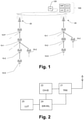
- Fig. 1 schematically shows a network architecture with relay communication devices.
- a 5G core network (CN) 100 is connected to a plurality of base stations (i.e. gNBs) 20 of a radio access network.
- First UEs 10-1 are directly or indirectly connected to a respective one of the base stations 20 and act as Relay UEs configured to transport upstream data from two or more downstream UEs 10-D to the respective (serving) base station 20 and downstream data from a respective base station 20 to the two or more downstream UEs 10-D.
- Relay UEs configured to transport upstream data from two or more downstream UEs 10-D to the respective (serving) base station 20 and downstream data from a respective base station 20 to the two or more downstream UEs 10-D.
- at least one parent UE 10-P may be connected as Relay UE between the first UE 10-1 and the respective base station 20.
- one or more downstream second UEs 10-2 that are in radio range (coverage) of a respective first UE 10-1 are provided, each capable of acting as either Remote UE or Relay UE or both and connecting directly to the respective first UE 10-1 over a wireless link and indirectly to a respective base station 20 via a relay function of the respective first UE 10-1.
- Dotted lines indicate possible/optional links to further UEs (not shown).
- the core network 100 may comprise network functions such as a network slice selection function (NSSF), a user plane function (UPF), a session management function (SMF), and an access and mobility management function (AMF).
- NSSF network slice selection function
- UPF user plane function
- SMF session management function
- AMF access and mobility management function
- the base stations 20 or a function in the core network 100 acting via the base stations 20 provides downstream data to the first UEs 10-1 that includes a data rate recommendation and/or limit for a logical channel ID (LCID).
- This data rate recommendation and/or limit for a single LCID contains an aggregate data rate recommendation and/or limit for at least two UEs.
- the first UE 10-1 determines at least partly based on the associated LCID which one(s) of the second UEs 10-2 are to receive a new data rate recommendation and/or limit.
- the first UE 10-1 provides downstream data to at least one of the second UEs 10-2 which includes a new data rate recommendation and/or limit, which is at least partly based on the received aggregate data rate recommendation and/or limit.
- the new data rate recommendation and/or limit provided by the first UE 10-1 may comprise a recommendation and/or limit value that is lower than the value of the aggregate recommendation and/or limit included in the received data.
- the new data rate recommendation and/or limit provided by the first UE 10-1 has a recommendation/limit value that is equal to the value of the aggregate data rate recommendation and/or limit included in said received data.
- the aggregate data rate recommendation and/or limit sent to the first UE 10-1 may comprise indicator data for indicating whether the aggregate data rate recommendation and/or limit applies to an upstream data flow or to a downstream data flow.
- a UE can send an aggregate desired data rate request for an LCID to an upstream UE or to a base station 20 that is in its radio range.
- At least one of the second UEs 10-2 may be arranged to transmit a desired data rate request for an LCID to a first UE 10-1, wherein the first UE 10-1 may respond to the request with a data rate recommendation and/or limit for that LCID and optionally for one or more other LCID(s).
- the first UE 10-1 may be arranged to send a desired data rate request for an LCID to an upstream UE (e.g. parent UE 10-P) or a base station 20 in radio range, where the request is triggered by and at least partly based on at least one desired data rate request received from a second UE 10-2.
- the upstream desired data rate request may contain a single desired data rate for the LCID, where the single desired rate may be the added total of a plurality of received desired data rates. If a look-up table of recommendation and/or limit values is used in an embodiment, the added total (sum) of desired data rates sent to the upstream UE (e.g. parent UE 10-P or the base station 20) is an approximation (e.g. the lowest value from the table that is at least equal to or larger than the sum of desired data rates).
- the first UE 10-1 may receive an aggregate data rate limit of e.g. 1Mbps from the parent UE 10-P or the base station 20 and may then split this into a first limit (e.g. 500 kbps) to use for itself and a second limit (e.g. 500 kbps) to use for the (one) second UE (i.e. child UE) 10-2. Or, in case of a received aggregate rate recommendation, this may be used for the first UE 10-1 itself (acting in Remote UE role, i.e. data producer/consumer itself, or acting in a regular UE role as data producer/consumer) and a child Remote UE of the first UE 10-1.
- second UEs 10-2 that do not have any further children themselves can be considered as Remote UEs.
- any distribution e.g. 20% for itself and 80% for one downstream UE may be implemented.
- a Relay UE may always be enabled to operate as a regular UE in "directly connected" mode too. Also, a Relay UE can be enabled to operate as Remote UE itself. Vice versa, a Remote UE can be enabled to operate as a Relay UE.
- the aggregate data rate recommendation and/or limit is interpreted by the first UE 10-1 and based thereon the first UE will generate and send a new data rate recommendation and/or limit to at least one downstream device.
- L3 layer-3
- L2 layer-2
- the first UE 10-1 may also have to add an RLC bearer or RLC channel (because RLC acts over just one hop) in order to send a new data rate recommendation. This may be triggered automatically or by an RRC setup procedure.
- the first UE 10-1 may receive an RRC rlc-BearerToAddModList element or a similar element defined for Sidelink RLC bearer creation such that it will also create a Radio Link Control (RLC) bearer and its associated logical MAC channel ID in response thereto.
- RLC Radio Link Control
- the aggregate data rate recommendation and/or limit may be passed downstream hop-by-hop by at least one Relay UE (e.g. the parent UE 10-P of the left branch in Fig. 1 ) to the first UE 10-1.
- the first UE 10-1 receives aggregate data rate recommendations and/or limits from the base station 20 via the relay function of the at least one Relay UE which could have even been modified by the at least one Relay UE in transit.
- the first UE 10-1 may receive its aggregate data rate recommendation and/or limit directly from the at least one upstream Relay UE and may not recognize that it is coming from the base station 20.
- the aggregate data rate recommendation and/or limit may be created by a parent UE 10-P (e.g. MAC CE Recommended Bit Rate like method) or by the access device 20 directly (e.g. sent via RRC over multiple relay hops to the relay UE 10-1). In both cases, a message carrying the aggregate data rate recommendation and/or limit may be sent by the parent UE 10-P to the first UE 10-1 while the creator of the message may differ.
- a parent UE 10-P e.g. MAC CE Recommended Bit Rate like method
- the access device 20 directly (e.g. sent via RRC over multiple relay hops to the relay UE 10-1).
- a message carrying the aggregate data rate recommendation and/or limit may be sent by the parent UE 10-P to the first UE 10-1 while the creator of the message may differ.
- Fig. 2 schematically shows a block diagram of a relay communication device according to various embodiments.
- the relay communication device of Fig. 2 may correspond to the first UE 10-1 of Fig. 1 or any other type of relay communication device for any wireless network having a data rate recommendation and/or limitation function.
- the relay communication device comprises a transceiver unit (TRX) 21 for transmitting and receiving wireless messages and/or other wireless signals via an antenna.
- TRX transceiver unit
- Messages with new data rate recommendations or limits are created by an individual data rate recommendation and/or limit creator (IDR-R/L) 24 based at least partially on a logical channel identity (ID) (e.g. LCID) derived by a channel detector (CH-ID) 22 from an aggregate data rate recommendation and/or limit received by the transceiver unit 21 from an access device (e.g. base station 20 of Fig. 1 ) or another upstream communication device (e.g. parent UE 10-P of Fig. 1 ).
- ID logical channel identity
- CH-ID channel detector
- the relay communication device comprises a memory with a look-up table (LUT) 25 which provides a mapping table between logical channel IDs of parent (upstream) devices and associated logical channel IDs of child (downstream) devices and/or remote downstream communication devices.
- LUT look-up table
- the individual data rate recommendation and/or limit creator 24 Based on information provided in the mapping table of the look-up table 25 and the aggregate data rate obtained from a received data rate recommendation and/or limit, the individual data rate recommendation and/or limit creator 24 creates a new data rate recommendation and/or limit for at least one of the one or more downstream communication devices and transmits the new data rate recommendation and/or limit through the logical channel with the derived logical channel ID to the derived downstream communication device and/or to the downstream communication device(s) listed in the mapping table in association with the received logical channel ID.
- the transmission may be directly or indirectly (e.g. over multiple hops, and/or via a network function).
- the relay communication device may create the new data rate recommendation and/or limit under consideration of its own desired data rate and/or data rate limitation(s).
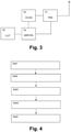
- Fig. 3 schematically shows a block diagram of an access device according to various embodiments.
- the access device of Fig. 3 may correspond to the base station (gNB) 20 of Fig. 1 or any other type of access device for any wireless network having a resource scheduling function.
- the access device comprises a transceiver unit (TRX) 31 for transmitting and receiving wireless messages and/or other wireless signals via an antenna.
- Messages with aggregate data rate recommendations and/or limits are generated by an aggregate data rate recommendation and/or limit creator (ADR-R/L) 34 based on a logical channel ID (e.g. LCID) derived by a channel detector (CH-ID) 32 from an aggregate desired data rate received by the transceiver unit 31 from a downstream communication device.
- the access device e.g. base station (gNB) 20 in Fig. 1
- the channel detector 32 does not act on received "desired data rate" messages, but on other considerations (e.g. available resources and a fair distribution of those).
- the access device comprises a memory with a look-up table (LUT) 35 which provides a mapping table between logical channel IDs and associated directly and indirectly connected remote downstream communication devices.
- the mapping table may be one table defined per directly connected communication device (e.g. Relay UE).
- the mapping table can be implemented as one table for all communication devices. In that case, e.g.
- LCID 4 may be mapped to Remote UEs ⁇ x,y,z ⁇ for directly connected Relay UE1 and may as well be mapped to different Remote UEs ⁇ a,b ⁇ for directly connected Relay UE2.
- the aggregate data rate recommendation and/or limit creator 34 Based on the received logical channel ID and aggregate desired data rate, the aggregate data rate recommendation and/or limit creator 34 creates at least one aggregate data rate recommendation and/or limit for downstream communication devices based on the information in the mapping table and transmits the at least one aggregate data rate recommendation and/or limit through the logical channel with the received logical channel ID.
- the mapping table is thus used by the access device to derive communication devices to be addressed, if it sends on a particular logical channel ID to a particular directly connected relay communication device.
- the transmission may be directly or indirectly (e.g. over multiple hops, and/or via a network function).
- the individual blocks of the block diagrams of Figs. 2 and 3 may be implemented by discrete hardware circuit(s) such as application specific integrated circuit(s) (ASIC(s)), programmable logic array(s) (PLA(s)), field programmable gate array(s) (FPGA(s)) or the like, or by digital signal processor(s) (DSP) or other software-controlled processor circuit(s).
- ASIC application specific integrated circuit
- PLA programmable logic array
- FPGA field programmable gate array
- DSP digital signal processor
- Fig. 4 schematically shows a flow diagram of an enhanced rate recommendation and/or limitation procedure according to various embodiments, which may be implemented at a relay communication device (e.g. first UE 10-1 of Fig. 1 ) of a cellular or other wireless network.
- a relay communication device e.g. first UE 10-1 of Fig. 1
- the relay communication device receives an aggregate data rate recommendation and/or limit from a parent communication device or an access device. Then, in step S402, a logical channel ID (e.g. LCID) is derived from the received aggregate data rate recommendation and/or limit. In step S403, associated logical channel IDs of downstream devices and/or associated remote communication devices are derived from a mapping table available at the relay communication device. Then, in step S404, a new data rate recommendation and/or limit with associated logical channel ID is created based at least partly on the received aggregate data rate recommendation and/or limit and the associated logical channel IDs of downstream devices and/or associated remote communication devices derived from the mapping table under optional consideration of own data rate requirements of the relay communication device.
- a logical channel ID e.g. LCID
- step S405 the created new data rate recommendation and/or limit is transmitted to one or more downstream communication devices.
- Fig. 5 schematically shows a flow diagram of an aggregate desired rate reporting procedure according to various embodiments, which may be implemented at an access device (e.g. base station (gNB) 20 of Fig. 1 or eNB or access point) of a cellular or other wireless network.
- an access device e.g. base station (gNB) 20 of Fig. 1 or eNB or access point
- gNB base station
- a first step S501 the access device receives from a downstream communication device an aggregate desired data rate for a logical channel. Then, in step S502, the logical channel ID (e.g. LCID) of the associated logical channel is determined. In step S503, a mapping table is consulted to derive from the determined logical channel ID associated directly and indirectly connected downstream communication devices. Then, in step S504, an aggregate data rate recommendation and/or limit is created based at least partly on the received aggregate desired data rate and the associated directly and indirectly connected downstream communication devices.
- the logical channel ID e.g. LCID
- step S505 the created aggregate data rate recommendation and/or limit is transmitted to the associated downstream communication device, i.e., back to the requesting device.
- This may be single-hop transmission over a logical channel e.g. as in a MAC CE, or a potential multi-hop transmission as in e.g. an IP packet, PDCP PDU, or RRC message.
- the original query of the desired data rate might have triggered a change in the resource allocations so that also recommendations and/or limits may be sent to other downstream devices, not only the requesting communication device, and may also be sent to other logical channels, not only the logical channel for which the data rate recommendation and/or limit was requested.
- steps of the flow diagrams of Figs. 4 and 5 may be implemented based on one or more software routines used for controlling a processor or computing unit provided in the relay communication device or the access device, respectively.
- transmission of the new and/or aggregate data rate recommendations or limits and/or aggregate desired data rates may be achieved by at least one of the following options:
- Fig. 6 schematically shows a network architecture with one-to-one mapping between LCIDs in the first UE according to an embodiment.
- a one-to-one mapping is implemented in the first UE (UE1) between respectively an LCIDi used between the first UE and its parent node (UEO) and an LCIDj used between the first UE (UE1) and a second UE (UE2, UE3), where the second UE may be a Relay UE (UE2), Remote UE (UE3), or both (UE2).
- the second UE (UE2) comprises both functionalities, because it also gets its own LCID for its own data.
- the first UE when the first UE (UE1) receives a data rate recommendation or limit from its parent node (UEO) indicating LCIDi, it can look up in an internal mapping table 25 the corresponding second UE (UE2 and/or UE3) and the LCIDj that identifies a logical channel for which to send a new data rate recommendation or limit to the second UE.
- the first UE when the first UE (UE1) receives a desired data rate request from a second UE (UE2 or UE3) indicating LCIDj, it can look up in the mapping table 25 the corresponding LCIDi to use when sending a new desired data rate request to its parent node (UE0), wherein the desired data rate value is at least partially based on the value received from second UE.
- the LCID can be in the range of "1" to "32".
- the first UE (U1, Relay UE) can support at most 32 second UEs given that each second UE needs at least one associated LCID for a logical channel assigned on the communication link between first UE and its parent node (UEO) to be able to communicate over a logical channel.
- More LCID values for uplink and downlink are defined in 3GPP Release 16 (e.g.
- a mapping may be created in a relay UE that maps the limited number of LCIDs to a larger number of LCIDs, e.g., by assigning a different LCID for each downstream UE that supports only a limited number of LCIDs and report to the upstream access device or relay UE the new LCID instead. In this way, older Remote UEs or Relay UEs can be supported in a backwards compatible manner.
- the mapping may also include for each downstream UE the number of LCIDs it supports or may include the version of the standard specification it supports (e.g. 3GPP uses "capability reporting" for this so more like a flag saying "support-extended:true”).
- the assigning of a new LCID may take this into account and e.g. only reserve values "4" to "19” for assignment to older downstream UEs, and reserve an extended set of values for newer downstream UEs.
- the upstream UE or access device is only capable of handling LCID values "4" to "19"
- the LCID for any upstream logical channel has to be chosen amongst those values.
- a second UE being a Relay UE (UE2) or Remote UE (UE3) or both (UE2)
- UE2 Relay UE
- UE3 Remote UE
- UE2 Remote UE
- this embodiment implies that the first UE will need to create an additional logical channel with an LCIDi on the wireless link with its parent node.
- the relayed data traffic coming from LCIDj of the second UE will then be transported over the logical channel LCIDi and vice versa incoming relayed data over LCIDi if forwarded will be sent over LCIDj to the second UE.
- Any bit rate recommendation or limit received for LCIDi will then trigger a creation of a new data rate recommendation and/or limit to be sent to the second UE indicating an LCIDj and indicating a recommendation or limit value that is typically equal to the received value.
- second UE(s) could optionally also implement the proposed enhanced recommendation or limitation procedure, acting like first UE and using a mapping table.
- the base station (gNB) 20 can send data rate recommendations and/or limits downstream using e.g. the Recommended Bit Rate MAC CE to e.g. a directly connected UE (UEO).
- the directly connected UE receiving these data rate recommendation and/or limits can use e.g. an equivalent Sidelink Recommended Bit Rate MAC CE to send a new data rate recommendation to the first UE (UE1) and/or e.g. an equivalent Sidelink Bit Rate Limit MAC CE to send a new data rate limit to the first UE (UE1).
- the first UE (UE1) receiving these recommendations and/or limits can use Sidelink Recommended Bit Rate MAC CEs to send new data rate recommendations to downstream second UEs (UE2, UE3).
- UE2, UE3 second UEs
- the base station (gNB) 20 of a Relay UE may request the creation of a new radio bearer (e.g. data radio bearer, DRB) or new RLC channel to first UE (UE1) using an RRC reconfiguration message sent from the base station 20 to the UE, in response to determining that a downstream UE of first UE (e.g. a second UE (UE2,UE3)) requires a new logical channel and/or determining that a new Relay UE or Remote UE downstream of first UE (e.g. UE2, UE3 or UE4) is added to the network topology.
- Using RRC messages may require control plane connectivity between the base station 20 and first UE.
- the request may trigger the creation of a new logical channel, associated to the new radio bearer, in first UE.
- the first UE requests to the core network (CN) 100 the establishment of a new PDU session after creation of a new radio bearer on first UE, or upon determining that a downstream UE requires a new logical channel and/or determining that a new Relay UE or Remote UE downstream of first UE is added to the network topology. This may require control plane connectivity between the base station 20 and first UE. If the core network accepts the new PDU session, the first UE uses this PDU session to relay data traffic between this particular downstream UE and the core network.
- CN core network
- self-selection of an LCID for a sidelink communication channel by one of the involved UEs can be used or any other mechanisms being considered in 3GPP for LCID selection for ProSe-D2D/V2X-SL communication.
- One possible implementation can also be that only Relay UEs directly in radio range of the base station 20 implement the embodiment using RRC messaging, while other UEs not in radio range of the base station 20 implement other embodiments.
- a radio bearer may be created on request of the base station 20, a communication device (UE) may request a new PDU session, or a communication device may select LCID(s) itself.
- UE communication device
- LCID LCID
- the first UE may send a lower recommendation or limit value to a second UE, instead of "equal" as defined earlier.
- a second UE instead of "equal" as defined earlier.
- the first UE uses a part of the capacity on channel LCIDi for its own purposes, which of course may only be possible in case sharing of a single logical channel (and corresponding data radio bearer, DRB) will be allowed by 3GPP specifications.
- the proposed one-to-one mapping between logical channels (LCIDi) of parent communication devices (P-CD) and logical channels (LCIDj) of child communication devices (CH-CD) in the mapping table 25 can be used for example for fine-grained recommended data rate control by an upstream node (e.g. base station (gNB) 20, or another parent Relay UE (UE0 in Fig. 6 ) of the first UE (UE1)).
- an upstream node e.g. base station (gNB) 20
- UE0 parent Relay UE
- the parent communication device has created logical channels P-LCID1, P-LCID3, P-LCID4, and P-LCID5 to the first UE (UE1) and the first UE (UE1) as child communication device has created logical channels CH-LCID3, CH-LCID4, CH-LCID4' and CH-LCID9 to the second UEs (UE2, UE3).
- P-LCID1 is associated with CH-LCID4' and UE3
- P-LCID3 is associated with CH-LCID4 and UE2
- P-LCID4 is associated with CH-LCID9 and UE2
- P-LCID5 has no associated logical channel on the child UE side (e.g.
- the two CH-LCID4s indicated in Fig. 6 are two distinct logical channels (a first CH-LCID4 between UE1 and UE2 and a second CH-LCID4' between UE1 and UE3).
- An LCID included within a MAC sub-header uniquely identifies a logical channel within the scope of the combination of Source Layer-2 ID and Destination Layer-2 ID.
- the upstream node When the upstream node (UEO) wants to recommend a data rate for a specific downstream Remote UE (UE3 or UE4 in Fig. 6 ), it can send a Sidelink Recommended Bit Rate MAC CE for the specific logical channel P-LCIDi (e.g. P-LCID1 in Fig. 6 ) which is associated to the Remote UE.
- P-LCIDi e.g. P-LCID1 in Fig. 6
- the first UE UE1 which is a Relay UE
- CH-LCIDj e.g. CH-LCID4' in Fig. 6
- mapping table 25 e.g. CH-LCID4' in Fig. 6
- CH-LCIDj e.g. CH-LCID4 in Fig. 6
- the first UE (UE1) will send the recommendation value, e.g. by using a new Sidelink Recommended Bit Rate MAC CE, directly to the next-hop Relay UE (UE2) in the path towards the Remote UE (UE4).
- the next-hop Relay UE (UE2) also applies the same algorithm as first UE (UE1), and so eventually the recommendation arrives at the targeted Remote UE (UE4).
- an upstream node e.g. base station (gNB) 20 or parent Relay UE (UE0)
- UE0 parent Relay UE
- an upstream node e.g. base station (gNB) 20 or parent Relay UE (UE0)
- gNB base station
- UE0 parent Relay UE
- RRC Radio Resource Control
- the base station uses RRC signaling to create a new data radio bearer (DRB) between itself and the Remote UE, as well as any new logical channels (e.g.
- DRB data radio bearer
- the parent Relay UE allocates new logical channel(s) to the new downstream child Remote UE.
- the parent Relay UE if not directly connected to the base station, uses the same or similar D2D communication to report the logical channel allocations to its next upstream parent Relay UE. This next parent in turn may create a new logical channel towards the reporting Relay UE. This next parent may in turn report the new logical channel allocations to its next upstream parent Relay, and so on.
- the final Relay UE that is in direct connection with the base station may report the aggregate collected information about logical channel identities and configurations to the base station using e.g. RRC signaling. Also it may initiate the process to create a new PDU session via core network functions.
- the core network may send the decision on creating a new PDU session to the base station (gNB) 20, via which it will also be sent to the requesting Relay UE.
- the base station can allocate a specific data radio bearer with own LCID(s) for the Relay UE for the new PDU session (one bearer may associate to one or more LCIDs, depending on bearer properties). This way the core network can be aware of the Remote UEs that are active for a given Relay UE, and the base station (gNB) 20 can also be aware of these Relay UEs and knows the associated LCIDi for each.
- the first UE may aggregate multiple desired bit rate messages from downstream UEs, that are received for example using Recommended Bit Rate MAC CE from child UEs or other means.
- the first UE reports these values upstream by mapping the CH-LCIDj for which it has received a message to a corresponding upstream P-LCIDi for which a new report message with aggregate desired bit rate is to be transmitted e.g. at a future point in time.
- Specific trigger conditions and/or timers can govern the time of upstream transmission(s).
- Multiple reports with desired bit rate messages about multiple P-LCIDi may be aggregated into a single upstream message.
- the first UE finds no match in the mapping table 25 towards a downstream second UE (UE2 or UE3) this could be handled as follows: If the P-LCIDi is used for the first UE's own communications, then it may use the aggregate bit rate recommendation itself.
- the first UE could ignore recommendation messages for this P-LCIDi for a certain amount of time.
- the base station (gNB) 20 may notice the new situation and may request for removal of P-LCIDi since the channel is no longer needed.
- the first UE (UE1) could return back an error message report for P-LCIDi to the upstream UE (UEO) or base station (gNB) 20 immediately or at a future point in time (e.g. included in a future/next MAC PDU that is sent).
- the first UE itself may initiate itself a procedure to remove or deactivate the logical channel indicated by the LCIDi and/or a data radio bearer associated to it. Or, the first UE itself may initiate a procedure to stop the PDU session related to P-LCIDi, if any, since this is no longer required now that the Remote UE has left.
- the first UE may ignore the message. This is an error situation that is not expected to occur frequently.
- a second UE may apply 3GPP power saving methods while staying connected to the first UE (UE1) as its parent Relay. It may thus happen that a second UE to which a recommendation/limit needs to be delivered is unavailable at the time that the first UE would like to send the recommended/limit bit rate.
- the first UE should cache the recommendation/limit and wait until the next occasion where either (1) data is to be sent to the second UE i.e. a MAC PDU, or (2) the second UE wakes up again and starts sending new data i.e. a MAC PDU to the first UE, and may then send the recommendation/limit.
- it may be included for example as a MAC CE inside the MAC PDU sent.
- it may be included for example as a MAC CE in a MAC PDU sent to the second UE following the event of the MAC PDU sent by the second UE to the first UE after the wake-up, or possibly as part of an ACK message sent by the first UE to the second UE to confirm reception of the data or MAC PDU.
- the old cached recommendation can be discarded.
- the second UE may have left and the corresponding options described above for the case of a non-available downstream second UE can be applied.
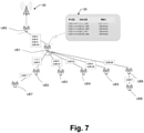
- Fig. 7 schematically shows a network architecture with one-to-many mapping between logical channels (LCIDs) in the first UE (UE1) according to various embodiments.
- LCIDs logical channels
- a one-to-many mapping is implemented in the first UE (UE1) between respectively a P-LCIDi (e.g. P-LCID1, P-LCID3, P-LCID4 and P-LCID15 in Fig. 7 ) used between the first UE and its parent node (UEO) and a CH-LCIDj (e.g. CH-LCID2, CH-LCID3, CH-LCID8, CH-LCID9, CH-LCID17, CH-LCID18, CH-LCID23 and CH-LCID29 in Fig. 7 ) used between the first UE (UE1) and a second UE (UE2 to UE6).
- P-LCIDi e.g. P-LCID1, P-LCID3, P-LCID4 and P-LCID15 in Fig. 7
- a CH-LCIDj e.g. CH-LCID2, CH-LCID3, CH-LCID8, CH-LCID9, CH-LCID17, CH-LCID18, CH-LCID23 and
- the first UE receives a data rate recommendation from its parent node (UEO) indicating P-LCIDi, it can look up in its internal mapping table 25 potentially multiple corresponding second UEs and potentially multiple corresponding CH-LCIDj that identify a logical channel for which to send a new data rate recommendation.
- UEO parent node
- a single aggregate data rate recommendation received from upstream P-LCIDI can map to five downstream second UEs (UE2, UE3, UE4, UE5 and UE6) with respective CH-LCID8, CH-LCID17, CH-LCID23, CH-LCID2 and CH-LCID29.
- a single data rate recommendation for P-LCID1 of 3000 kbit/s may map to five downstream data rate recommendations ("REC" in mapping table 25) of respectively 1000 kbit/s for CH-LCID8 to UE2, 500 kbit/s for CH-LCID17 to UE3, 500 kbit/s for CH-LCID23 to UE4, 500 kbit/s for CH-LCID2 to UE5 and 500 kbit/s for CH-LCID29 to UE6.
- REC data rate recommendations
- the first of these downstream UEs may be given priority based on some quality of service (QoS) related policy executed by the first UE, as explained later.
- QoS quality of service
- Any quality indicator of a logical channel (upstream, downstream, relay-related, non-relay-related, etc.) or multiple quality indicators coming from multiple logical channels could be used by the first UE (UE1) for the policy execution.
- An alternative policy could allocate more bit rate to UE2 and UE6 because these are relays with further downstream UEs (UE7, UE8), so they could potentially have higher need for bandwidth.
- a single aggregate data rate recommendation received on, or indicating, logical upstream channel P-LCID1 could map to two second UEs, first one with three logical downstream channels CH-LCID8, CH-LCID9 and CH-LCID10 and a second one with one logical downstream channel CH-LCID16.
- the first UE when the first UE (UE1) receives a desired data rate request from a second UE indicating CH-LCIDj, it can look up in the mapping table 15 the corresponding P-LCIDi to use when sending a new desired data rate request to its parent node (UE0), wherein the desired data rate value is at least partially based on the value received from second UE.
- a new second UE (either Relay (such as UE2 and UE6) or Remote (such as UE3 to UE5) or both) connects to the first UE (UE1)
- this embodiment does not require that the first UE will request an additional logical channel with a new P-LCIDi on the wireless link with its parent node (UEO).
- the relayed data traffic of the new second UE can be transported in principle over an existing logical channel (e.g. P-LCID1) between the first UE (UE1) and its parent node (UEO).
- the first UE may transmit downstream recommendation/limit values to second UEs, the sum of these being lower than the received aggregate recommendation/limit value from an upstream device.
- This is useful for example if the first UE (UE1) has limited buffer space available and needs to reduce its buffer sizes, or if it needs to use some capacity of the same upstream P-LCIDi itself.
- a table may be used that maps a bitrate ID value to an actual bit rate. Then, the sum of recommendations sent downstream must not exceed the received aggregate recommendation value.
- the first UE may not further send a downstream recommendation/limit to a second UE if that recommendation does not substantially deviate from an earlier recommendation/limit sent to that same UE.
- the first UE may perform fair sharing of bitrate between multiple downstream UEs.
- all Relay/Remote UEs may use the Sidelink Recommended Bit Rate MAC CE or another MAC CE in their communication with upstream and downstream nodes.
- the first UE may be configured to carry relay-related data traffic upstream over one or more separate logical channels, while data of the first UE (UE1) itself to/from the base station (gNB) 20 (not related to relaying operations performed by first UE) may be transferred using different logical channel(s).
- the first UE receives from its upstream node (UEO) a Sidelink Recommended Bit Rate MAC CE and the included P-LCIDi is a relay-related logical channel, then it first identifies the set of all involved downstream UEs that have their data flowing through this logical channel.
- the first UE has received a recommendation data rate value Vrec for this logical channel P-LCIDi. Then, it maps for every set member the LCID to a downstream CH-LCIDj (which could be same or different value) and sends to every member a Recommended Bit Rate MAC CE that includes a new recommendation value Vrec _ i ⁇ Vrec, wherein the sum over i of all Vrec_i does not exceed the value Vrec.
- the available data rate recommendation can be distributed over the set of potentially multiple downstream UEs.
- the above distribution can be made fair by using a previously received desired data rate (e.g. using a recommended data rate query mechanism as described above) of each set member (i.e. downstream UE) to guide the distribution of the recommended data rate.
- a UE in the set that desires twice as much data rate as another UE in the set will receive approximately twice as much recommended data rate as the other UE.
- Fig. 8 schematically shows an example of network architecture with one-to-many channel mapping where a single logical channel indicates relayed data of a group of communication devices.
- the first UE sends an aggregate desired data rate request to the base station (gNB) 20 which may respond with an aggregate recommended data rate, wherein a policy is used to distribute data rate recommendations to downstream UEs.
- This embodiment covers first collecting a number of desired data rates received from downstream UEs and then sending the combined number (aggregate desired data rate) to the base station (gNB) 20 and then receiving a recommended data rate total value (aggregate data rate recommendation) from the base station (gNB) 20, which is then distributed to downstream UEs using a policy.
- a single logical channel P-LCID5 used by the first UE indicates all relayed data of a group of UEs consisting of all downstream UEs of the first UE (UE1).
- a mapping table 25 of the first UE maps logical parent channel P-LCID5 to a group of all downstream UEs (UE2 to UE4) indicated by "A" in the mapping table.
- a logical parent channel P-LCID1 is used for own data (OD) of the first UE (UE1).
- a mapping table 25 of the parent Relay UE maps logical parent channels P-LCID25, P-LCID26 and P-LCID27 to own data (OD) usage of the parent Relay UE (UE0), the logical channel CH-LCID5 of child device UE1, and the logical channel CH-LCID1 of child device UE1, respectively, wherein the logical parent channel P-LCID25 is used for own data (OD) of the parent relay UE (UEO).
- the first UE (UE1) sends one aggregate desired bit rate value upstream (indicating e.g. a logical channel P-LCID5), which is approximately the sum of desired bit rates received from multiple child UEs (Relays and/or Remotes) that are allocated to the same upstream logical channel P-LCID5 of the first UE (UE1).
- P-LCID5 a logical channel
- the parent relay UE receives the aggregate desired bit rate value from the first UE (UE1) and sends the same value upstream to the base station (gNB) 20 as aggregate desired bit rate for a logical channel P-LCID26.
- the base station (gNB) 20 receives the one aggregate desired total bit rate message indicating P-LCID26 and due to the LCID information contained in the message it can determine for which group of UEs (UE2 to UE4 encircled as a group in Fig. 8 ) the aggregate desired bit rate holds, regardless of whether the determined UEs (UE2 to UE4) are directly or indirectly connected to first UE (UE1).
- Fig. 9 schematically shows an example of network architecture with unique downstream LCIDs, i.e., one data rate recommendation/limit is used per Remote UE.
- a mapping table 25 used by the first UE (UE1) of Fig. 9 does not indicate a UE in this example.
- the downstream LCIDs are unique values and the mapping table 25 therefore does not need to indicate a child UE by its identity anymore.
- the identity of a child UE directly follows from the LCID as downstream LCIDs are unique.
- the mapping table 25 maps logical parent channels P-LCID1, P-LCID3, P-LCID4 and P-LCID5 to unique logical child channels CH-LCID4 of child device UE2, CH-LCID5 of child device UE3, and CH-LCID9 of child device UE2, respectively, wherein the logical parent channel P-LCID5 is not mapped to any downstream logical channel yet.
- base station (gNB) 20 can send individual data rate recommendations and/or limits to a selected Remote UE (e.g. UE3) just by picking the right channel (e.g. P-LCID3), assuming that all traffic on that channel is related to that particular Remote UE.
- a selected Remote UE e.g. UE3
- P-LCID3 the right channel
- each Relay UE has SL links setup with its child UEs so it knows the L2 identity (ID) per child, per the V2X sidelink solution described in 3GPP specification TS 23.287 v16.2.0, therefore it can use L2 child UE identities in the mapping table 25.
- the base station (gNB) 20 knows the entire relay network topology (e.g. based on previous channel creation, configuration and/or commissioning procedures and/or reporting procedures of communication devices or the like) and that in relation to the topology the base station (gNB) 20 knows the purpose of the different logical channels and/or radio bearers created and/or used by UEs (e.g. relaying data traffic purpose) and their associated LCIDs. So, in the example of Fig. 8 , the base station (gNB) 20 knows that by sending an aggregate recommendation value to UE0 for the logical channel P-LCID26 this value will get distributed as a new recommendation to the first UE (UE1) indicating logical channel CH-LCID5.
- the base station (gNB) 20 knows the entire relay network topology (e.g. based on previous channel creation, configuration and/or commissioning procedures and/or reporting procedures of communication devices or the like) and that in relation to the topology the base station (gNB) 20 knows the purpose of the different logical channels and/or radio bearers
- the base station (gNB) 20 also knows that first UE (UE1) will distribute this value over its downstream second UEs (UE2 and UE3) using a selected policy, where the relay-type UE (UE2) of the second UEs may also share the received aggregate data rate recommendation from the first UE (UE1) over itself (UE2) and its child UE (UE4).
- the exact sharing method (policy) used by the first UE (UE1) may also be known by the base station (gNB) 20 in case that the policy of data rate distribution is governed by the base station (gNB) 20 (e.g. through RRC configuration messages). If the policy is fixed (another option), then the base station (gNB) will know the fixed policy being used.
- the base station (gNB) 20 knows that a recommendation value sent to the parent Relay UE (UEO) for logical channel P-LCID26 will be sent as a new recommendation with equal recommendation value to logical channel CH-LCID5 of the parent Relay UE (UEO) which equals the logical channel P-LCID5 of the first UE (UE1).
- the base station (gNB) 20 determines a total recommended data rate value (aggregate data rate recommendation) for the group of UE(s) (UE2 to UE4).
- the total recommended data rate value of the aggregate data rate recommendation is sent back to the parent Relay UE (UEO) as a Recommended Bit Rate MAC CE element indicating the same logical channel P-LCID26 as was indicated in the aggregate desired bit rate message.
- UEO Relay UE
- the parent Relay UE sends a new Sidelink Recommended Bit Rate MAC CE indicating logical channel CH-LCID5 to the first UE (UE1).
- the first UE applies a policy to distribute the recommended bit rate among the UEs (UE2 to UE4) that are in the group of UEs as indicated by above logical channel LCID5. This may include downstream UE(s) and the first UE (UE1) itself.
- the first UE (UE1) may send new recommendations only to UE2 and UE3 (i.e. its children). Then, UE2 may send another new recommendation further to its child UE4.
- the policy may be applied with a goal to distribute recommendations to the whole group.
- the policy could be the fair-sharing policy described above or any other one. It may be configurable by the base station (gNB) 20 or by a function in the core network.
- the logical channel CH-LCID5 indicates all its child UEs ("A" in the mapping table 25 of the first UE (UE1)).
- the first UE (UE1) sends to each of the child UEs a recommended data rate message (Sidelink Recommended Bit Rate MAC CE or another MAC type of CE) including a value that is approximately a specific fraction/portion of the total recommended data rate value of the aggregate data rate recommendation according to the selected policy.
- a recommended data rate message (Sidelink Recommended Bit Rate MAC CE or another MAC type of CE) including a value that is approximately a specific fraction/portion of the total recommended data rate value of the aggregate data rate recommendation according to the selected policy.
- child UE2 After child UE2 receives the recommended data rate message from first UE, it may apply a policy to assign a specific fraction/portion of the total recommended data rate it received to its child UE4 and assign the remainder to itself. It may then send a recommended data rate message (e.g. Sidelink Recommended Bit Rate MAC CE or other MAC CE) containing the assigned data rate to its child UE4.
- a recommended data rate message e.g. Sidelink Recommended Bit Rate MAC CE or other MAC CE
- an example of a policy could be to provide more data rate to a Relay UE than to a Remote UE, since a Relay UE may need to further distribute the data rate budget to downstream UEs while a Remote-only UE does not.
- the embodiments described herein can be implemented with another MAC CE element, or a modified one, that defines a data rate limit instead of a recommendation.
- the Recommended Bit Rate MAC CE could be re-used as such but could also be defined as a different type of MAC CE such as Sidelink Bit Rate Limit MAC CE or other type.
- the data rate limit carried by the MAC CE element may be expressed as an Aggregated Maximum Bit Rate (AMBR), e.g. per logical channel or set of logical channels, or other type.
- AMBR Aggregated Maximum Bit Rate
- both types of information may be carried in separate MAC CE elements or a combined new MAC CE element.
- the recommendation and/or limit may be defined as a relative value, e.g., relative to a maximum data rate that a child UE can support e.g. over a sidelink connection towards a parent Relay UE.
- a relative value e.g., relative to a maximum data rate that a child UE can support e.g. over a sidelink connection towards a parent Relay UE.
- it may be calculated similar to the DL and UL maximum data rate supported by the UE (e.g. as defined in section 4.1.2 of 3GPP specification TS 38.306 v16.0.0).
- the access device or parent Relay UE may transmit the recommendation and/or limit to a downstream UE encoded e.g. as an indicator of a fraction or percentage of the supported maximum sidelink data rate of that downstream UE.
- the parent Relay UE may know the parameters required for doing the maximum sidelink data rate calculation due to its communication link with the downstream UE.
- the downstream UE may also calculate its own maximum sidelink data rate based on these parameters, so that it can derive the absolute recommendation and/or limit values from the received relative (e.g. fraction/percentage) indicator values.
- a configurable policy may be implemented in the Relay UE (e.g. the first UE) and extra bits may optionally be added in a MAC CE element or other conveying message to be able to select a policy (out of a finite number of policies) to apply in the Relay UE.
- the Recommended Bit Rate MAC CE has a couple of 'reserved' unused bits which could be used for this purpose.
- bits may be repurposed to select a policy in the downstream Relay UE to apply, wherein the selected policy influences the distribution of recommended bit rate to its further-downstream UEs.
- policies may be predefined per specification of a selected standard (e.g. 3GPP), preconfigured, or configured using RRC at the moment that a UE becomes a Relay UE.
- a set of policies to choose from may also be selected based on a QoS indicator that is known by the Relay UE to be related to the specific LCID indicated in the MAC CE element.
- Example policies could be "distribute up to 90% of recommended bit rate fairly between all high-priority logical channels and distribute the remaining 10% fairly between low-priority logical channels" or “use up to 40% of recommended bit rate for yourself and distribute the remaining 60% fairly between downstream UEs”.
- a configurable policy may be used in the Relay UE (e.g. first UE), wherein the policy selection for the distribution policy when receiving a bit rate recommendation from an upstream communication device can be based on the value of a quality indicator (e.g. 5G QoS indicator, such as the 5QI value).
- a quality indicator e.g. 5G QoS indicator, such as the 5QI value.
- a quality indicator may be known in the Relay UE for each logical channel identity (LCID) it uses.
- Examples are a MAC CE element that combines a recommended value plus a limit (e.g. maximum) value, or a MAC CE element that includes an integer number denoting a bit rate value (e.g. kbit/sec) instead of an integer category or class number.
- various ways of sending the data rate information to the Relay UE (e.g. first UE) or Remote UE can be used.
- Examples are MAC CE, PDCP protocol (can be end-to-end from base station (gNB) to Relay UE or single hop e.g. from a Relay UE to a Remote UE, or single hop e.g. from a Relay UE to a Relay UE), RRC protocol (e.g.
- gNB base station
- Relay UE can be end-to-end from base station (gNB) to Relay UE or single hop (e.g. from a Relay UE to a Remote UE or from a Relay UE to a Relay UE)).
- Relay UEs when to send an upstream message with desired data rate request information can be:
- Relay UEs when to send a recommendation received from an upstream node (UE or base station (gNB) to one or more downstream nodes
- UE or base station gNB
- An example may be using the existing Recommended Bit Rate MAC CE as defined in 3GPP specification TS 38.321 v15.5.0. Multiple of these can be sent in a single MAC PDU if needed, or multiple can be sent distributed over multiple MAC PDUs.
- a message could consist of a list of tuples: ⁇ LCID_i, UL/DL or upstream/downstream or UL/DL/SL_i, Data Rate recommendation i ⁇
- a message could consist of a list of tuples: ⁇ UE-ID_k, LCID_i, UL/DL_i, Data Rate recommendation_i ⁇ where UE-ID is a short identifier for a specific Remote/Relay UE in the RAN, or for a specific Remote/Relay UE downstream of the message's sender (this would allow IDs to be encoded even shorter, in principle).
- a message could consist of a list of tuples: ⁇ LCID_i, UL/DL_i, Data Rate recommendation_i, Data Rate limit_i ⁇
- the above format examples can be wrapped in a MAC CE or transported via one of the other protocols described above.
- the base station (gNB) could decide based on received reports that a Relay UE or Remote UE needs an additional upstream Relay UE on top of its current one. Because if not, the desired data rate of one or more crucial data streams (e.g. high-priority, real-time, or low-latency data) cannot be met. To fulfill this need, the base station (gNB) may instruct a specific Relay UE or Remote UE to acquire an additional parent Relay UE or to initiate a replacement by new parent Relay UE that can provide more bandwidth (i.e. data rate).
- the base station (gNB) may instruct a specific Relay UE or Remote UE to acquire an additional parent Relay UE or to initiate a replacement by new parent Relay UE that can provide more bandwidth (i.e. data rate).
- the base station (gNB) and its scheduler may control and/or influence a recommended data rate for one logical channel (LCID1) for at least one specific UE (e.g. UE1) that is directly connected to the base station (gNB), triggered by receiving new information about a (aggregate) desired data rate for another logical channel (LCID2) on a UE (e.g. UE2, where either UE1 may or may not equal UE2).
- LCID1 logical channel
- UE1 logical channel 1
- UE2 e.g. UE2
- UE2 e.g. UE2
- the base station (gNB) or its scheduler may for example schedule less resources for LCID1 and more for LCID2 if UE2 for LCID2 indicates that more data rate is desired there, and vice versa, or schedule more resources for LCID1 and less for LCID2 if UE2 for LCID2 indicates less data rate is required/desired.
- a related embodiment may be to send lower recommended data rate than previous on LCID1 if UE2 for LCID2 indicates that more data rate is desired there, and vice versa, or to send higher recommended data rate than previous on LCID1 if UE2 for LCID2 indicates less data rate is required/desired.
- the sent recommendations may be respectively lower/higher because respectively less/more resources are available for LCID1 in above cases.
- the Relay UE may reduce data rate recommendation(s) to downstream UEs when its buffer fills above a threshold or may adapt its data rate recommendation(s) to downstream UE(s) based on its buffer status.
- the Relay UE may start a policy of reducing the recommended data rate to downstream UE(s).
- the reduction of recommended data rate could be specific for one or more LCID(s) depending on the status of the upstream data buffer for a specific upstream LCID.
- the Relay UE may start to apply its original policy again without any reduction of recommendation(s).
- a data rate recommendation has been initially created by a base station (gNB) and then sent to one or more Relay UEs. In this way, the data rate recommendation "trickles down" into the local part of the cellular network initiated by the base station (gNB).
- initiation mechanisms e.g. RRC or SDAP or PDCP
- data rate recommendations and/or limits can be used.
- control messages from the core network, i.e., coming from any function in the core network that carry such information.
- Such other messages may be used to convey e.g. slice-specific data limits for uplink to be adhered to by a UE, or recommendations to follow by a UE.
- the recommendation and/or limitation control messages sent to one or more downstream UE(s) may be based on received data rate recommendation/limit information and may be sent using another protocol than the one used to receive the recommendation/limit.
- the Recommended Bit Rate MAC CE or Sidelink Recommended Bit Rate MAC CE could be used to send a recommended data rate value to child UE(s) by the Relay UE (e.g. first UE), based on a limit sent through an extended SDAP protocol message.
- a recommendation is sent based on a limit value.
- Downstream UEs may be OoC without access to most base station functions and/or core network functions, e.g., they could be unable to use control plane messaging to/from a base station or to establish a PDU session with the core network.
- the OoC UEs can still receive data rate recommendations indirectly via the Relay UE and apply the recommendations to their upstream data.
- the Relay UE may send a limit value to downstream UE(s) based on above data rate limit information, e.g., using a newly defined Sidelink Bit Rate Limit MAC CE or similar.
- a further way to potentially send a data rate limit/recommendation to a downstream UE is via the RRC protocol over Sidelink (SL), i.e., the PC5 interface.
- SL Sidelink
- relay communication devices can be introduced to support an indirect network connection for remote communication devices in OoC areas to thereby extend access device coverage and increase available data capacity for communication devices that may not be in optimal coverage of an access device.
- mechanisms for bit rate recommendation, bit rate query and desired bit rate indication are defined.
- these existing mechanisms do not work for communication devices indirectly connected via a relay communication device. It is therefore proposed to determine a new data rate recommendation and/or limit for one or more downstream communication devices at least partly based on an identity of a logical channel indicated in a received recommendation and/or limit.
- the proposed enhanced rate recommendation or limitation can be implemented in all types of wireless networks where relays are used. E.g., it can be applied to devices communicating using cellular wireless communication standards, specifically the 3 rd Generation Partnership Project (3GPP) 5G specifications.
- 3GPP 3 rd Generation Partnership Project
- the wireless communication devices can be different types of devices, e.g. mobile phones, vehicles (for vehicle-to-vehicle (V2V) communication or more general vehicle-to-everything (V2X) communication), V2X devices, IoT hubs, IoT devices, including low-power medical sensors for health monitoring, medical (emergency) diagnosis and treatment devices, for hospital use or first-responder use, virtual reality (VR) headsets, etc.
- V2V vehicle-to-vehicle
- V2X vehicle-to-everything
- IoT hubs IoT devices, including low-power medical sensors for health monitoring, medical (emergency) diagnosis and treatment devices, for hospital use or first-responder use, virtual reality (VR) headsets, etc.
- VR virtual reality
- the invention can be applied in medical applications or connected healthcare in which multiple wireless (e.g. 4G/5G) connected sensor or actuator nodes participate, in medical applications or connected healthcare in which a wireless (e.g. 4G/5G) connected equipment consumes or generates occasionally a continuous data stream of a certain average data rate, for example video, ultrasound, X-Ray, Computed Tomography (CT) imaging devices, real-time patient sensors, audio or voice or video streaming devices used by medical staff, in general IoT applications involving wireless, mobile or stationary, sensor or actuator nodes (e.g. smart city, logistics, farming, etc.), in emergency services and critical communication applications, in V2X systems, in systems for improved coverage for 5G cellular networks using high-frequency (e.g. mmWave) RF, and any other application areas of 5G communication where relaying is used.
- a wireless (e.g. 4G/5G) connected equipment consumes or generates occasionally a continuous data stream of a certain average data rate, for example video, ultrasound, X-Ray,
- a single unit or device may fulfill the functions of several items recited in the claims.
- the mere fact that certain measures are recited in mutually different dependent claims does not indicate that a combination of these measures cannot be used to advantage.
- the described operations like those indicated in Figs. 4 and 5 can be implemented as program code means of a computer program and/or as dedicated hardware of the related communication device or access device, respectively.
- the computer program may be stored and/or distributed on a suitable medium, such as an optical storage medium or a solid-state medium, supplied together with or as part of other hardware, but may also be distributed in other forms, such as via the Internet or other wired or wireless telecommunication systems.
Landscapes
- Engineering & Computer Science (AREA)
- Computer Networks & Wireless Communication (AREA)
- Signal Processing (AREA)
- Quality & Reliability (AREA)
- Mobile Radio Communication Systems (AREA)
Priority Applications (8)
| Application Number | Priority Date | Filing Date | Title |
|---|---|---|---|
| EP20196334.5A EP3968722A1 (de) | 2020-09-15 | 2020-09-15 | Verbesserte ratensignalisierung in drahtlosen netzwerken mit relaisfunktion |
| BR112023004458A BR112023004458A2 (pt) | 2020-09-15 | 2021-09-14 | Aparelho, dispositivo de comunicação de retransmissão, sistema de comunicação sem fio e método |
| CN202180063208.6A CN116326123A (zh) | 2020-09-15 | 2021-09-14 | 具有中继功能的无线网络中的增强速率信令 |
| PCT/EP2021/075146 WO2022058290A1 (en) | 2020-09-15 | 2021-09-14 | Enhanced rate signaling in wireless networks with relay function |
| JP2023516708A JP2023542106A (ja) | 2020-09-15 | 2021-09-14 | 中継機能を有するワイヤレスネットワークにおける強化レート信号伝達 |
| MX2023002916A MX2023002916A (es) | 2020-09-15 | 2021-09-14 | Se?alizacion de tasa mejorada en redes inalambricas con funcion de retransmision. |
| EP21777498.3A EP4215002A1 (de) | 2020-09-15 | 2021-09-14 | Signalisierung mit erhöhter rate in drahtlosen netzwerken mit relaisfunktion |
| US18/025,976 US20230354103A1 (en) | 2020-09-15 | 2021-09-14 | Enhanced rate signaling in wireless networks with relay function |
Applications Claiming Priority (1)
| Application Number | Priority Date | Filing Date | Title |
|---|---|---|---|
| EP20196334.5A EP3968722A1 (de) | 2020-09-15 | 2020-09-15 | Verbesserte ratensignalisierung in drahtlosen netzwerken mit relaisfunktion |
Publications (1)
| Publication Number | Publication Date |
|---|---|
| EP3968722A1 true EP3968722A1 (de) | 2022-03-16 |
Family
ID=72521467
Family Applications (1)
| Application Number | Title | Priority Date | Filing Date |
|---|---|---|---|
| EP20196334.5A Withdrawn EP3968722A1 (de) | 2020-09-15 | 2020-09-15 | Verbesserte ratensignalisierung in drahtlosen netzwerken mit relaisfunktion |
Country Status (1)
| Country | Link |
|---|---|
| EP (1) | EP3968722A1 (de) |
Cited By (1)
| Publication number | Priority date | Publication date | Assignee | Title |
|---|---|---|---|---|
| WO2023001171A1 (zh) * | 2021-07-23 | 2023-01-26 | 维沃移动通信有限公司 | 推荐比特率确定方法、装置及相关设备 |
Citations (3)
| Publication number | Priority date | Publication date | Assignee | Title |
|---|---|---|---|---|
| EP2066084A1 (de) * | 2007-11-27 | 2009-06-03 | Nokia Siemens Networks Oy | Drahtloses Telekommunikationssystem mit Basisstation, Relaisknoten und Verfahren zur globalen Terminplanung |
| EP3051736A1 (de) * | 2015-01-30 | 2016-08-03 | Panasonic Intellectual Property Corporation of America | Priorisierung im Verfahren zur logischen Kanalpriorisierung für logische Sidelink-Kanäle in ProSe-Direktkommunikationen |
| EP3255950A1 (de) * | 2016-06-06 | 2017-12-13 | ASUSTek Computer Inc. | Verfahren und vorrichtung zur ressourcenzuweisung für ein d2d relais in einem drahtloskommunikationssystem |
-
2020
- 2020-09-15 EP EP20196334.5A patent/EP3968722A1/de not_active Withdrawn
Patent Citations (3)
| Publication number | Priority date | Publication date | Assignee | Title |
|---|---|---|---|---|
| EP2066084A1 (de) * | 2007-11-27 | 2009-06-03 | Nokia Siemens Networks Oy | Drahtloses Telekommunikationssystem mit Basisstation, Relaisknoten und Verfahren zur globalen Terminplanung |
| EP3051736A1 (de) * | 2015-01-30 | 2016-08-03 | Panasonic Intellectual Property Corporation of America | Priorisierung im Verfahren zur logischen Kanalpriorisierung für logische Sidelink-Kanäle in ProSe-Direktkommunikationen |
| EP3255950A1 (de) * | 2016-06-06 | 2017-12-13 | ASUSTek Computer Inc. | Verfahren und vorrichtung zur ressourcenzuweisung für ein d2d relais in einem drahtloskommunikationssystem |
Non-Patent Citations (1)
| Title |
|---|
| ETSI ETSI: "5G; NR; Medium Access Control (MAC) protocol specification (3GPP TS 38.321 version 15.3.0 Release 15)", 1 September 2018 (2018-09-01), pages 2018 - 9, XP055779987, Retrieved from the Internet <URL:https://www.etsi.org/deliver/etsi_ts/138300_138399/138321/15.03.00_60/ts_138321v150300p.pdf> [retrieved on 20210226] * |
Cited By (1)
| Publication number | Priority date | Publication date | Assignee | Title |
|---|---|---|---|---|
| WO2023001171A1 (zh) * | 2021-07-23 | 2023-01-26 | 维沃移动通信有限公司 | 推荐比特率确定方法、装置及相关设备 |
Similar Documents
| Publication | Publication Date | Title |
|---|---|---|
| JP6983216B2 (ja) | 送信装置、方法および集積回路 | |
| JP6652577B2 (ja) | リモートueに応対するproseリレーのための改善されたスケジューリングメカニズム | |
| WO2020192778A1 (zh) | 一种混合自动重传请求harq反馈控制方法及相关设备 | |
| RU2708300C2 (ru) | Процедура приоритизации логического канала для логических каналов одноуровневой линии связи | |
| CN108207036B (zh) | 一种半持久调度的方法及装置 | |
| US11160107B2 (en) | Method for performing a LCP procedure in wireless communication system and a device therefor | |
| US20230345456A1 (en) | Enhanced scheduling in wireless networks with relay function | |
| WO2021109429A1 (en) | Access network signaling and resource allocation for multicast/broadcast sessions | |
| US20180359765A1 (en) | Method for allocating priorities to a logical channel group implicitly in a d2d communication system and device therefor | |
| US20230262734A1 (en) | Access network signaling and resource allocation for multicast/broadcast sessions | |
| US20230354103A1 (en) | Enhanced rate signaling in wireless networks with relay function | |
| US20230038562A1 (en) | Methods and infrastructure equipment | |
| US8976743B2 (en) | Method and apparatus for transmitting and receiving resource allocation scheme information in a wireless communication system | |
| US20230370902A1 (en) | Relay UE Selection for Transmission Over Sidelink | |
| CN113475145A (zh) | 用于在无线通信系统中减少调度时延的方法和装置 | |
| EP3968722A1 (de) | Verbesserte ratensignalisierung in drahtlosen netzwerken mit relaisfunktion | |
| KR20200027288A (ko) | 차량 통신을 지원하는 무선통신 시스템에서 단말간 통신을 위한 자원 요청 방법 및 장치 | |
| CN113615293B (zh) | 逻辑信道优先级的协调 | |
| EP3902352A1 (de) | Verbesserte planung in drahtlosen netzwerken mit relaisfunktion | |
| CN111757499A (zh) | 资源管理方法、控制信息传输方法、以及信息配置方法 | |
| WO2023013608A1 (ja) | 通信方法 | |
| WO2023072258A1 (en) | Method and apparatus for carrier aggregation | |
| US20220393806A1 (en) | Method and device for determining transmission priority | |
| CN115696273A (zh) | 通信方法、装置及系统 |
Legal Events
| Date | Code | Title | Description |
|---|---|---|---|
| PUAI | Public reference made under article 153(3) epc to a published international application that has entered the european phase |
Free format text: ORIGINAL CODE: 0009012 |
|
| STAA | Information on the status of an ep patent application or granted ep patent |
Free format text: STATUS: THE APPLICATION HAS BEEN PUBLISHED |
|
| AK | Designated contracting states |
Kind code of ref document: A1 Designated state(s): AL AT BE BG CH CY CZ DE DK EE ES FI FR GB GR HR HU IE IS IT LI LT LU LV MC MK MT NL NO PL PT RO RS SE SI SK SM TR |
|
| STAA | Information on the status of an ep patent application or granted ep patent |
Free format text: STATUS: THE APPLICATION IS DEEMED TO BE WITHDRAWN |
|
| 18D | Application deemed to be withdrawn |
Effective date: 20220917 |