EP3965247A1 - Mobile network distribution system - Google Patents
Mobile network distribution system Download PDFInfo
- Publication number
- EP3965247A1 EP3965247A1 EP21190484.2A EP21190484A EP3965247A1 EP 3965247 A1 EP3965247 A1 EP 3965247A1 EP 21190484 A EP21190484 A EP 21190484A EP 3965247 A1 EP3965247 A1 EP 3965247A1
- Authority
- EP
- European Patent Office
- Prior art keywords
- loading area
- cable
- distribution system
- mobile network
- connection
- Prior art date
- Legal status (The legal status is an assumption and is not a legal conclusion. Google has not performed a legal analysis and makes no representation as to the accuracy of the status listed.)
- Pending
Links
Images


Classifications
-
- H—ELECTRICITY
- H02—GENERATION; CONVERSION OR DISTRIBUTION OF ELECTRIC POWER
- H02J—CIRCUIT ARRANGEMENTS OR SYSTEMS FOR SUPPLYING OR DISTRIBUTING ELECTRIC POWER; SYSTEMS FOR STORING ELECTRIC ENERGY
- H02J3/00—Circuit arrangements for ac mains or ac distribution networks
- H02J3/007—Arrangements for selectively connecting the load or loads to one or several among a plurality of power lines or power sources
- H02J3/0073—Arrangements for selectively connecting the load or loads to one or several among a plurality of power lines or power sources for providing alternative feeding paths between load and source when the main path fails, e.g. transformers, busbars
-
- H—ELECTRICITY
- H02—GENERATION; CONVERSION OR DISTRIBUTION OF ELECTRIC POWER
- H02B—BOARDS, SUBSTATIONS OR SWITCHING ARRANGEMENTS FOR THE SUPPLY OR DISTRIBUTION OF ELECTRIC POWER
- H02B1/00—Frameworks, boards, panels, desks, casings; Details of substations or switching arrangements
- H02B1/26—Casings; Parts thereof or accessories therefor
- H02B1/52—Mobile units, e.g. for work sites
-
- H—ELECTRICITY
- H02—GENERATION; CONVERSION OR DISTRIBUTION OF ELECTRIC POWER
- H02G—INSTALLATION OF ELECTRIC CABLES OR LINES, OR OF COMBINED OPTICAL AND ELECTRIC CABLES OR LINES
- H02G11/00—Arrangements of electric cables or lines between relatively-movable parts
-
- Y—GENERAL TAGGING OF NEW TECHNOLOGICAL DEVELOPMENTS; GENERAL TAGGING OF CROSS-SECTIONAL TECHNOLOGIES SPANNING OVER SEVERAL SECTIONS OF THE IPC; TECHNICAL SUBJECTS COVERED BY FORMER USPC CROSS-REFERENCE ART COLLECTIONS [XRACs] AND DIGESTS
- Y04—INFORMATION OR COMMUNICATION TECHNOLOGIES HAVING AN IMPACT ON OTHER TECHNOLOGY AREAS
- Y04S—SYSTEMS INTEGRATING TECHNOLOGIES RELATED TO POWER NETWORK OPERATION, COMMUNICATION OR INFORMATION TECHNOLOGIES FOR IMPROVING THE ELECTRICAL POWER GENERATION, TRANSMISSION, DISTRIBUTION, MANAGEMENT OR USAGE, i.e. SMART GRIDS
- Y04S10/00—Systems supporting electrical power generation, transmission or distribution
- Y04S10/50—Systems or methods supporting the power network operation or management, involving a certain degree of interaction with the load-side end user applications
- Y04S10/52—Outage or fault management, e.g. fault detection or location
Definitions
- the subject relates to a mobile network distribution system, in particular for an electrical low-voltage network.
- Errors occur irregularly and unpredictably in electrical low-voltage networks, which means that the participants (loads and/or feeders) connected to the low-voltage networks are disconnected from the electrical low-voltage network and, in particular, cannot draw or feed in any energy.
- this fault is detected at the grid connection point and the phase is separated from the rest of the network.
- the participants in the thread are de-energized and a repair of the thread is initiated.
- the object was therefore based on the object of making available a system with which an initial supply can be provided flexibly and quickly for participants in electrical energy networks after a fault has occurred.
- the mobile network distribution system is designed in particular to provide electrical networks with powers between 50kVA and 800kVA, preferably between 90kVA and 650kVA, in particular between 90kVA and 400kVA, preferably between 250kVA and 400kVA.
- a low-voltage network is connected to a higher network level, in particular a medium-voltage network, at the network connection point via a transformer.
- Transformers with outputs between 90kVA and 650kVA are used for this, depending on the number of strands that the transformer serves and the type of participants arranged on the strands.
- Faults can occur along only one outgoing leg of a transformer, i.e. one leg is faulty and can be shed, but the transformer will still function properly.
- a fault can also occur in or on the transformer or at the grid connection point or along all strands, so that the transformer as such can no longer be used.
- the transformer can be replaced by an emergency power system, for example a mobile generator, and new cables are laid along the strands, starting from the emergency power system.
- a mobile network distribution system which is loaded on a mobile trailer with at least one loading area and one axle.
- the mobile trailer has one or two axles and can be connected to a towing vehicle via a trailer hitch.
- the mobile trailer can, for example, be coupled directly to the trailer hitch of a truck on which the emergency power system is loaded.
- the mobile trailer can also be coupled to any other vehicle and thus be taken quickly and easily from the depot to the location of the fault.
- connection field with at least three single-phase input connections is provided on the loading area.
- the system can be connected to the emergency power system or the existing transformer via this connection panel.
- a respective input connection is provided for each phase.
- three connections are provided for the phases L1, L2, L3 and at least one connection for the combined or possibly separate neutral conductor and/or the potential earth.
- the connection panel can have further input connections for neutral conductors and/or grounding conductors.
- the input connections are connected to the emergency power system or the transformer using commercially available, conventional plug-in couplings that are easily available.
- the network distribution system can thus easily and without problems over the input connections at the location of the fault Standard components can be connected to the still functional transformer or the network system.
- a distribution box is also mounted on the loading area for distributing the electrical power.
- the distribution box has an input field and at least two, preferably more than two, in particular six, outgoing fields.
- a second distribution box can also be mounted on the loading area in order to increase the number of outgoing panels; a three-phase output connection can be provided on each outgoing panel. In this way, the network distribution system can serve one branch with one or more participants via the output connections.
- the input panel is hardwired to the input terminals of the connector panel.
- a busbar can be provided for each phase, the neutral conductor and/or the grounding conductor, which busbars are each hard-wired to one of the input terminals on the input panel.
- the output panels can be coupled to the respective busbars and each have a three-phase output connection on the output side.
- connection consoles be mounted on the loading area.
- the connection consoles can be mounted directly or indirectly on the loading area.
- the respective connection consoles are each connected to the output connections, with one connection console being connected to an output connection of an output field, in particular being hard-wired.
- the connection consoles are preferably designed as plug-in couplings for distribution cables.
- the system in question is characterized by the fact that it is mounted on a trailer and can therefore be moved to the place of use in a mobile manner and as required.
- the service technician who is on duty to rectify the fault can simply plug the distribution cables into the plug-in couplings and connect them to the house connections.
- the output connections can be secured via the distribution box.
- the connector panel is particularly easy to install on a working one Infrastructure such as a functioning transformer or an emergency power system.
- the network distribution system thus makes it possible for the service technician to provide the subscribers with an initial supply after a fault in a particularly quick and simple manner via the distribution cable.
- At least one, preferably a plurality of distribution cables designed as extension cables is loosely stored on the loading area.
- Distribution cables with different lengths for example 10m, 25m, 50m or the like, can be stored on the loading area.
- the distribution cables can be taken from the loading area by the service technician and connected to the plug-in couplings of the connection consoles, as well as routed to the participants. Chains can also be formed by several distribution cables lined up in a row.
- the distribution cables allow the network distribution system to be connected to the participants above ground.
- the distribution cables are conventional, rubber-coated cables with cable cross-sections between 16mm 2 and 25mm 2 .
- the distribution cables are formed with terminal plug-in couplings.
- the distribution cables can be conventional CEE extension cables with rubber jackets.
- the distribution cables usually have five lines for the phases L1, L2, L3 as well as N and earth.
- the plug-in couplings are in particular CEE plugs, which are standardized and are designed for currents of over 40A, in particular up to 63A.
- the plug-in coupling of the connection console is designed in particular as a socket for receiving a plug of a distribution cable.
- the various distribution cables allow the service technician to flexibly wire the distribution system to the participants.
- the distribution cables are mounted on a cable drum, with the cable drum being mounted fixedly, pivotably fixedly or loosely on the loading area.
- a fixed or pivotally fixed cable drum is coupled to the trailer and the distribution cable can be unwound from the cable drum by the trailer.
- Loosely stored cable drums are suitable for further laying away from the distribution system.
- the cable can be easily transported via the cable drum and laid where it is needed. Because the cable drum can be pivoted, narrow outlet radii can also be implemented directly on the distribution system.
- the performance requirements of different participants may differ. It is also possible that, starting from the distribution system, a first distribution cable is routed at a connection to a sub-distribution and sub-distribution to a plurality of subscribers takes place there. Due to these very different performance requirements for the cables, it is proposed for flexible use of the network distribution system that the distribution cables with different cable cross sections are stored loosely on the loading area.
- loosely stored means that the components are removably stored on the trailer.
- the components can be fixed for transport, they can be removed in particular without tools.
- Loose storage can be in boxes, suitcases, carriers or by lashing or hooking. During transport, the components can be stored at a fixed location on the loading area, but for use the components can then be removed from there, in particular without tools, and taken away from the loading area.
- the cables can also have different cable lengths, for example 10m, 25m and 50m, so that a flexible Distribution in the area of the disorder is possible. Since the cables are intended to supply subscribers in a low-voltage network and, if necessary, long line lengths with high performance requirements are implemented, it is also proposed that the line cross sections of the lines or the cables be 16 mm 2 or more. In particular, the line cross sections are between 16 mm 2 and 250 mm 2 , preferably between 16 mm 2 and 35 mm 2 .
- the cables have an outer insulation. In the outer insulation, which can be formed as rubber insulation, individual lines, each of which is insulated individually, are routed.
- the lines can be core lines or stranded lines and in particular made of copper or copper alloys. If lines are mentioned in this context, the line covered with the insulation can be meant on the one hand and the metallic wire or strand on the other.
- the lines or cables can each also be shielded.
- connection cable with a plug-in coupling at its first end and stripped cable ends at its second end be stored loosely on the loading area.
- an electrical connection is made in particular at the subscriber's house connection box or network connection point.
- the difference between different network connection points, in particular different house connection boxes with their different topologies and connection options, means that the connection cable for the final connection to the subscriber has stripped cable ends on one side.
- a ferrule, an eyelet, a bolt or the like can be connected to these line ends in order to establish a connection with the network connection point of the subscriber.
- a distribution box is provided on the network distribution system.
- An input field and at least two output fields are provided on this distribution box.
- fuses can be provided on the input panel.
- fuses can be provided on the respective connection panels. In particular, provision is made for one fuse per phase to be provided on the input panel. Provision is also made for one fuse per phase to be provided on the respective output field.
- a needs-based protection of the input field and output fields is necessary for mobile, dynamic use in the event of a fault.
- the fuses are in particular standard fuses that can be plugged into sockets in the input field and/or the output fields.
- the fuses can have different fuse characteristics, in particular they can have a wide variety of tripping currents.
- the appropriate fuse can then be plugged into the receptacle of the input field or one of the output fields, so that the participant and the distribution system can be protected as required.
- At least one mobile electrical sub-distribution board with at least one input and at least two outputs be loosely mounted on the loading area.
- the input as well as the outputs can be formed as a plug-in coupling for the distribution cable.
- the plug-in couplings are preferably standardized, in particular CEE couplings. It can make sense to branch off with a first distribution cable from the connection console on the loading area to a sub-distributor. From there, two or more distribution cables can branch off from the outputs and be routed to the participants.
- a first distribution cable is connected to the network distribution system.
- the connection cable is then connected to the stripped end of the line, via which the network connection point of the subscriber is connected.
- the input connections are provided with plug-in couplings for the connection of the power distribution system to a transformer or an emergency power system.
- the input connections are single-phase and the plug-in connectors are standardized plug-in connectors specifically designed for this purpose. In the case of connection to an emergency power system, this usually has a rollable cable with plug-in couplings that can be plugged into the input connections. In the event of a connection to a functioning transformer, a rollable cable can be provided separately for each input connection on the loading area.
- the plug-in couplings on the input connections, connection consoles, distribution cables and/or distribution boxes can be protected in particular against splashing water.
- the distribution cable with the stripped cable ends is electrically connected to the subscriber's network connection point.
- plugging in, screwing in, screwing, clamping, screwing on or the like can take place.
- the network connection point is electrically protected, for example by a cover or the like. This is the case in particular in the case of a house junction box. Such a cover has to be removed in order to establish contact for interference suppression, and that Distribution cables are connected with the stripped ends.
- at least one insulation cover for a house connection box be mounted loosely on the storage area. The service technician can open the house connection box, connect the cable and then cover the electrical contacts with the insulating hood so that they cannot be touched.
- the mobile trailer have fixed side walls delimiting the storage area.
- a preferably rear side wall can also be pivotable, in particular about a horizontal axis, but also rear side walls pivotable by two vertical axes.
- a cover can also be provided, which can also be pivoted about a horizontal axis and can be fastened to the side walls.
- a further advantageous aspect can be a measuring device which is electrically contacted on the input field and/or the output field.
- current and voltage can be measured using such a measuring device.
- the current can, for example, be measured via the cables by Rogowski coils provided on the measuring device.
- the actual consumption in the event of a fault or the power flows in the event of a fault can be measured.
- the measuring device can be read remotely, so that the power flows and the functionality of the distribution system can always be monitored during the provisional fault clearance.
- a position determination device in particular a GPS receiver, is provided on the trailer, which can also be read out remotely. This can be used to determine the position of the distribution system.
- FIG. 1 shows two mobile distribution systems 2, each mounted on a trailer 4 and pulled by a tractor 6.
- the two systems 2 can be used independently of one another and are only shown twice for illustration purposes.
- a system 2 can be electrically connected to a backup power system 8, as will be shown below.
- a system 2 can also be connected to a network connection point 10 . Both arrangements, both with the emergency power system 8 and with the grid connection point 10, are present at the input connections of the systems 2.
- subscribers 12 can be supplied with emergency power via distribution cables 14 with the electrical supply network. The cabling from the systems 2 to the participants 12 takes place via a large number of different distribution cables 14.
- a possible topology is in 2 shown.
- a grid error has occurred in the grid area shown schematically.
- an emergency power system 8 is relocated to the site together with a system 2 .
- the system 2 is then wired to the emergency power system 8 on the one hand and to the subscribers 12 on the other.
- Distribution cables 14 branch off from the system 2 for the distribution of the electrical energy to the subscribers 12 or they are laid manually above ground.
- the distribution cable 14 can also be lengthened on the way from the system 2 to the subscriber 12 by being connected to one another via plug-in couplings 16 .
- Sub-distributors 18 can also be provided, which are also connected to the distribution cables via plug-in couplings 16 .
- connection cable 20 can be routed to the network connection point of the subscriber.
- the connecting cable 20 can have a plug-in coupling 16 on one side, with which it can be connected to the distribution cable 14 .
- the connection cable 20 can have exposed lines on the opposite side, via which an electrical connection to the house distribution box or another network connection point of the subscriber 12 is possible.
- system 2 and emergency power system 8 are relocated to the site.
- the connection cables 20 are then connected to the house connection boxes and the house connection boxes connected in this way are connected to the output connections of the system 2 via the plug-in couplings 16 and the distribution cables 14 .
- the system 2 is connected to the emergency power system.
- a distribution box is equipped with the appropriate fuses.
- the emergency power system 8 is first switched on and then the fuse in the distribution box of the system 2 is switched on, so that the provisional supply network is energized and the subscribers 12 are supplied with electricity.
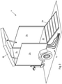
- the system 2 is on a trailer 4, as in the 3 shown mounted.
- the trailer 4 has a loading area 22.
- Various components are fixedly or loosely mounted on the loading area 22, as will be described below.
- three side walls 24 are preferably fixedly attached to the truck bed.
- a fourth side wall 26 is pivoted about a horizontal axis on the loading area 22 so that the loading area 22 can be reached via this side wall 26 .
- Doors and openings as well as cable bushings and connection consoles, in particular plug-in couplings, can be mounted in the side walls 24 so that assembly is possible from the outside.
- the distribution cables 14 can be brought out of the side walls 24 and connected and laid as required.
- a cover 28 can cover the system 2 from above.
- the loading area 22 can be completely closed via the side walls 24, 26 and the cover 28, so that after the installation of the emergency power supply, it can be closed and operated unattended without any danger to life and limb.
- a connection panel 34 is provided on the input side of the system 2 .
- the connector panel 34 can, for example, according to the figure 5 be educated.
- a double connector panel in which a single-core rubber cable 38 is provided on each cable drum 36 for connection to a network connection point.
- the cables 38 are all equipped with standardized plug-in couplings 39 and can thus be connected to connection consoles of a network connection point without tools or almost without tools.
- the connection panel 34 can also have permanently installed plug-in couplings.
- the corresponding emergency power system 8 with cable drum 36 and cable 38 as in figure 5 be equipped as described and thus, starting from the emergency power system, the system 2 can be connected to the connection panel 34 .
- the cables 38 of the connection panel 34 are hard-wired to an input panel of a connection box 40.
- the junction box 40 is an example in 6 shown.
- the junction box 40 can be a standard junction box with a housing and an opening door. On the input side, the connection box 40 can have an input panel 42 .
- the cables 38 are each connected to one of the terminals of the input panel 42 . Starting from the input panel 42, one busbar is led horizontally to the output panels 44 in each case.
- One receptacle for a plug-in fuse can be provided at the connections of the input field 42 and the output fields 44 per phase and per field. Starting from the fuses of the output fields 40, the individual phases are routed to three-phase output connections 46.
- the junction box 40 has an input panel 42 and six output panels 44 and thus six output terminals 46.
- the output terminals 46 are connected to the phases L1, L2, L3 via the output panels 44.
- busbars are the Output terminals also connected to the neutral and ground conductors.
- the fuse holders of the input panel 42 and the output panel 44 are unloaded, but are set up to be loaded with standard fuses by plugging them in.
- the output ports 46 are connected to port panels 50 on the system 4, such as 4 displays.
- port panels 50 on the system 4, such as 4 displays.
- connection console 50 is a standardized CEE socket, which enables a three-phase including neutral conductor and grounding conductor to be connected to a plug-in coupling of a distribution cable.
- a storage box 52 is provided on the loading area 22 for storing fuses with a wide variety of fuse characteristics.
- the fuses can be stored here, preferably sorted according to fuse characteristic or nominal value.
- Distribution cables are, in particular, standard cables 14, as specified in 8 are shown, which are terminally provided with standardized plugs and sockets.
- these cables can be 14 five-core cables with cable cross-sections of 16 mm 2 .
- the cables 14 can be rubber-coated and the plug-in couplings can be splash-proof.
- the cables can be shielded.
- a sub-distributor 58 as in the 10 be stored loosely shown on the loading area 22.
- the sub-distributor 58 has an input for connection to a distribution cable 14 and two or more outputs for connection to a distribution cable 14 .
- connection cables 60 are stored on the loading area 22.
- the connecting cables 60 are provided with a plug-in coupling on one side in order to be plugged into the distribution cable 14 .
- the cables 60 are stripped so that they can be connected to a house distribution box.
- the stripped ends can be provided with eyelets, cable end sleeves or the like.
- a position module can be mounted on the loading area 22, for example a GPS module, a Glonass module, a Galileo module or the like, which in particular can be read out remotely and makes the position of the system 2 determinable.
- a measuring device (not shown) can be connected to the input field 42 and/or one or more phases of the output field 44, with which the power flows on the individual phases and/or the individual output connections 46 and/or the input connections can be measured in emergency operation. This allows the emergency system to be monitored and evaluated.
- One or more hoods 62 can also be provided on the loading area 22, which are used to protect an open house connection box or another network connection point on a subscriber.
- the system 2 In the event of a fault, the system 2 is attached to a tractor 6 with the trailer hitch 2 and relocated to the fault. If an emergency power system 8 is necessary, it can also be relocated there.
- connection cables 60 are electrically connected to the house connection boxes of the subscribers 12 by first disconnecting the disrupted network previously connected to the house connection box and then placing the individual phases, the neutral conductor and the grounding conductor.
- the connection cables 60 are then optionally connected to the connection consoles 40 via the sub-distribution board 58 and via at least one distribution cable 14 .
- the emergency power system 8 is connected to the input field 42 of the connection box 40 via the cable 38 .
- fuses are plugged in and switched over as required.
- the network is then set up provisionally and the participants 12 are supplied with electricity.
Abstract
Mobiles Netzverteilsystem umfassend einen mobilen Anhänger mit zumindest einer Achse und einer Ladefläche, ein auf der Ladefläche montiertes Anschlussfeld mit zumindest drei jeweils einphasigen Eingangsanschlüssen, zumindest einen Verteilkasten, der über ein Eingangsfeld mit den jeweiligen Eingangsanschlüssen verbunden ist und über zumindest zwei Ausgangsfelder mit jeweils zumindest zwei zumindest dreiphasigen Ausgangsanschlüssen verbunden ist, und zumindest zwei Anschlusskonsolen, die jeweils mit den Ausgangsanschlüssen verbunden sind und als Steckkupplungen für Verteilkabel gebildet sind.Mobile network distribution system comprising a mobile trailer with at least one axle and a loading area, a connection panel mounted on the loading area with at least three single-phase input connections, at least one distribution box which is connected via an input panel to the respective input connections and via at least two output panels each with at least two at least three-phase output terminals is connected, and at least two connection panels, which are each connected to the output terminals and are formed as plug-in couplings for distribution cables.
Description
Der Gegenstand betrifft ein mobiles Netzverteilsystem, insbesondere für ein elektrisches Niederspannungsnetz.The subject relates to a mobile network distribution system, in particular for an electrical low-voltage network.
In elektrischen Niederspannungsnetzen treten unregelmäßig und unvorhersehbar Fehler auf, die dazu führen, dass die an die Niederspannungsnetze angeschlossenen Teilnehmer (Lasten und/oder Einspeiser) vom elektrischen Niederspannungsnetz getrennt sind und insbesondere keine Energie beziehen oder einspeisen können. Im Falle eines Fehlers entlang eines Strangs eines Niederspannungsnetzes wird dieser Fehler am Netzverknüpfungspunkt detektiert und der Strang wird vom restlichen Netz getrennt. Die Teilnehmer an dem Strang werden spannungslos gesetzt und eine Reparatur des Strangs wird in Gang gesetzt.Errors occur irregularly and unpredictably in electrical low-voltage networks, which means that the participants (loads and/or feeders) connected to the low-voltage networks are disconnected from the electrical low-voltage network and, in particular, cannot draw or feed in any energy. In the event of a fault along a phase of a low-voltage network, this fault is detected at the grid connection point and the phase is separated from the rest of the network. The participants in the thread are de-energized and a repair of the thread is initiated.
In der Regel ist eine Reparatur eines Niederspannungsstrangs jedoch mit Tiefbauarbeiten verbunden, da insbesondere in Deutschland ein Großteil der zumindest städtischen Niederspannungsnetze im Tiefbau verlegt ist. Im Grunde ist dies unproblematisch, kann jedoch vereinzelt zu Ressourcenengpässen führen. Insbesondere müssen die Wartungstrupps für solche Wartungsarbeiten in Bereitschaft gehalten werden. Für den Fall das mehrere Fehler gleichzeitig auftreten, reichen die Ressourcen nicht aus. Auch Fehler zu Nachtzeiten oder an Wochenenden oder Feiertagen sind problematisch, da das Vorhalten einer Wartungsbereitschaft extrem teuer ist. Andererseits ist es notwendig, dass Störungsende so schnell wie möglich nach Eintritt der Störung herbeizuführen. Dies hat zweierlei Gründe. Einerseits ist es den Teilnehmern nicht zuzumuten, zu lange ohne elektrische Energieversorgung auszukommen. Andererseits besteht jedoch häufig auch durch regulatorische Vorgaben der Zwang zu einer schnellen Störungsbeseitigung. Dabei kann die Dauer einer Störung bis zur Behebung der Störung relevant für eine Pönale sein. Daher ist es für den Netzbetreiber von großer Bedeutung, möglichst schnell ein Störungsende herbeizuführen. Aus den oben genannten Gründen ist dies bisher nicht immer möglich.As a rule, however, a repair of a low-voltage line is associated with civil engineering work, since a large part of the at least urban low-voltage networks is laid in civil engineering, particularly in Germany. Basically, this is not a problem, but it can occasionally lead to resource bottlenecks. In particular, the maintenance crews must be kept on standby for such maintenance work. If several errors occur at the same time, the resources are not sufficient. Errors at night or on weekends or public holidays are also problematic, since maintaining readiness for maintenance is extremely expensive. On the other hand, it is necessary to bring about the end of the disruption as quickly as possible after the disruption has occurred. There are two reasons for this. On the one hand, the participants cannot be expected to manage without an electrical power supply for too long. On the other hand, however, there is often a need for rapid troubleshooting due to regulatory requirements. The duration of a disruption until the disruption is rectified can be relevant for a penalty be. It is therefore of great importance for the network operator to bring about an end to the fault as quickly as possible. For the reasons mentioned above, this has not always been possible.
Dem Gegenstand lag daher die Aufgabe zugrunde, ein System zur Verfügung zu stellen, mit dem flexibel und schnell eine Erstversorgung von Teilnehmern an elektrischen Energienetzen nach Eintritt einer Störung bereitgestellt werden kann.The object was therefore based on the object of making available a system with which an initial supply can be provided flexibly and quickly for participants in electrical energy networks after a fault has occurred.
Diese Aufgabe wird durch ein mobiles Netzverteilsystem nach Anspruch 1 gelöst.This object is achieved by a mobile network distribution system according to
Das mobile Netzverteilsystem ist insbesondere dazu ausgelegt, elektrische Netze mit Leistungen zwischen 50kVA und 800kVA, bevorzugt zwischen 90kVA und 650kVA, insbesondere zwischen 90kVA und 400kVA, bevorzugt zwischen 250kVA und 400kVA zur Verfügung zu stellen. In der Regel ist ein Niederspannungsnetz am Netzverknüpfungspunkt über einen Transformator an eine höhere Netzebene, insbesondere ein Mittelspannungsnetz angeschlossen. Transformatoren mit Leistungen zwischen 90kVA und 650kVA werden hierfür eingesetzt, je nach Anzahl der Stränge, die der Transformator bedient und der Art der an den Strängen angeordneten Teilnehmer. Störungen können entlang nur eines Abgangsstrangs eines Transformators auftreten, d.h. ein Strang ist fehlerhaft und kann abgeworfen werden, der Transformator funktioniert jedoch nach wie vor einwandfrei. Auch kann in oder am Transformator oder am Netzverknüpfungspunkt oder entlang aller Stränge ein Fehler auftreten, sodass der Transformator als solcher nicht mehr eingesetzt werden kann.The mobile network distribution system is designed in particular to provide electrical networks with powers between 50kVA and 800kVA, preferably between 90kVA and 650kVA, in particular between 90kVA and 400kVA, preferably between 250kVA and 400kVA. As a rule, a low-voltage network is connected to a higher network level, in particular a medium-voltage network, at the network connection point via a transformer. Transformers with outputs between 90kVA and 650kVA are used for this, depending on the number of strands that the transformer serves and the type of participants arranged on the strands. Faults can occur along only one outgoing leg of a transformer, i.e. one leg is faulty and can be shed, but the transformer will still function properly. A fault can also occur in or on the transformer or at the grid connection point or along all strands, so that the transformer as such can no longer be used.
Im ersten Fall ist zur Störungsbeseitigung der Anschluss der Teilnehmer des gestörten Strangs an den bisherigen Transformator möglich, wobei jedoch eine neue Leitungsverlegung entlang des gestörten Strangs erfolgt. Im zweiten Fall kann durch eine Netzersatzanlage, beispielsweise ein mobiler Generator, der Transformator ersetzt werden und eine neue Leitungsverlegung entlang der Stränge erfolgt ausgehend von der Netzersatzanlage.In the first case, it is possible to connect the subscribers of the faulty line to the previous transformer to eliminate the fault, but with a new line being laid along the faulty line. In the second case, the transformer can be replaced by an emergency power system, for example a mobile generator, and new cables are laid along the strands, starting from the emergency power system.
Um zu vermeiden, dass zur Behebung des Fehlers langwierige Fehlersuche und Baumaßnahmen notwendig sind, wird ein mobiles Netzverteilsystem vorgeschlagen, welches auf einem mobilen Anhänger mit zumindest einer Ladefläche und einer Achse geladen ist. Der mobile Anhänger ist dabei ein- oder zweiachsig und kann über eine Anhängerkupplung mit einem Zugwagen verbunden werden. Der mobile Anhänger kann beispielsweise unmittelbar an die Anhängerkupplung eines Lkws, auf den die Netzersatzanlage geladen ist, angekoppelt werden. Auch kann der mobile Anhänger an ein jegliches anderes Fahrzeug angekoppelt werden und so vom Betriebshof schnell und einfach an die Störungsstelle herangeführt werden.In order to avoid lengthy troubleshooting and construction work being necessary to rectify the error, a mobile network distribution system is proposed which is loaded on a mobile trailer with at least one loading area and one axle. The mobile trailer has one or two axles and can be connected to a towing vehicle via a trailer hitch. The mobile trailer can, for example, be coupled directly to the trailer hitch of a truck on which the emergency power system is loaded. The mobile trailer can also be coupled to any other vehicle and thus be taken quickly and easily from the depot to the location of the fault.
Für die Störungsbehebung ist es zunächst nicht notwendig, dass der Fehler selbst behoben wird sondern vielmehr, dass die Teilnehmer schnell an das Versorgungsnetz angeschlossen werden. Hierzu ist auch eine provisorische, oberirdische Leitungsverlegung möglich, die durch den mobilen Anhänger in einer besonders flexiblen Weise bereitgestellt wird. Auf der Ladefläche des mobilen Anhängers lässt sich das notwendige Equipment leicht anordnen, um für die verschiedenen Fehlerfälle und unterschiedlichen Topologien und notwendige Verlegewege gerüstet zu sein.In order to rectify the fault, it is not initially necessary for the fault to be rectified itself, but rather for the participants to be quickly connected to the supply network. For this purpose, a provisional, above-ground line laying is possible, which is provided by the mobile trailer in a particularly flexible manner. The necessary equipment can be easily arranged on the loading area of the mobile trailer in order to be prepared for the various faults and different topologies and necessary laying routes.
Zunächst wird vorgeschlagen, dass auf der Ladefläche ein Anschlussfeld mit zumindest drei jeweils einphasigen Eingangsanschlüssen vorgesehen ist. Über dieses Anschlussfeld lässt sich das System mit der Netzersatzanlage oder dem vorhandenen Trafo koppeln. Für jede Phase ist ein jeweiliger Eingangsanschluss vorgesehen. Im Falle des typischen Drehstromnetzes sind drei Anschlüsse für die Phasen L1, L2, L3 sowie mindestens ein Anschluss für den kombinierten oder ggf. separierten Neutralleiter und/oder der Potentialerde vorgesehen. Somit kann das Anschlussfeld neben den drei Phasen weitere Eingangsanschlüsse für Neutralleiter und/oder Erdungsleiter aufweisen. Die Verbindung der Eingangsanschlüsse mit der Netzersatzanlage oder dem Trafo erfolgt über handelsübliche, herkömmliche Steckkupplungen, die einfach verfügbar sind. Das Netzverteilsystem kann somit am Ort der Störung über die Eingangsanschlüsse leicht und unproblematisch über Standartkomponenten mit dem noch funktionsfähigen Transformator oder der Netzanlage verbunden werden.First of all, it is proposed that a connection field with at least three single-phase input connections is provided on the loading area. The system can be connected to the emergency power system or the existing transformer via this connection panel. A respective input connection is provided for each phase. In the case of the typical three-phase network, three connections are provided for the phases L1, L2, L3 and at least one connection for the combined or possibly separate neutral conductor and/or the potential earth. Thus, in addition to the three phases, the connection panel can have further input connections for neutral conductors and/or grounding conductors. The input connections are connected to the emergency power system or the transformer using commercially available, conventional plug-in couplings that are easily available. The network distribution system can thus easily and without problems over the input connections at the location of the fault Standard components can be connected to the still functional transformer or the network system.
Für die Verteilung der elektrischen Leistung ist weiterhin auf der Ladefläche ein Verteilkasten montiert. Der Verteilkasten verfügt über ein Eingangsfeld und zumindest zwei, bevorzugter Weise mehr als zwei, insbesondere sechs Abgangsfelder. Auch kann ein zweiter Verteilkasten auf der Ladefläche montiert sein um die Anzahl der Abgangsfelder zu erhöhen, an jedem Abgangsfeld kann ein dreiphasiger Ausgangsanschluss vorgesehen sein. Somit kann das Netzverteilsystem über die Ausgangsanschlüsse jeweils einen Strang mit einem oder mehreren Teilnehmern bedienen. Das Eingangsfeld ist mit den Eingangsanschlüssen des Anschlussfeldes fest verdrahtet. Dabei kann für jede Phase, den Nullleiter und/oder den Erdungsleiter eine Sammelschiene vorgesehen sein, die am Eingangsfeld jeweils mit einem der Eingangsanschlüsse fest verdrahtet sind. Die Ausgangsfelder können mit den jeweiligen Sammelschienen gekoppelt sein und ausgangsseitig jeweils einen dreiphasigen Ausgangsanschluss aufweisen.A distribution box is also mounted on the loading area for distributing the electrical power. The distribution box has an input field and at least two, preferably more than two, in particular six, outgoing fields. A second distribution box can also be mounted on the loading area in order to increase the number of outgoing panels; a three-phase output connection can be provided on each outgoing panel. In this way, the network distribution system can serve one branch with one or more participants via the output connections. The input panel is hardwired to the input terminals of the connector panel. In this case, a busbar can be provided for each phase, the neutral conductor and/or the grounding conductor, which busbars are each hard-wired to one of the input terminals on the input panel. The output panels can be coupled to the respective busbars and each have a three-phase output connection on the output side.
Zur Kopplung der Ausgangsanschlüsse mit Verteilkabeln wird vorgeschlagen, dass auf der Ladefläche zumindest zwei Anschlusskonsolen montiert sind. Dabei können die Anschlusskonsolen unmittelbar oder mittelbar auf der Ladefläche montiert sein. Die jeweiligen Anschlusskonsolen sind jeweils mit den Ausgangsanschlüssen verbunden, wobei jeweils eine Anschlusskonsole mit einem Ausgangsanschluss eines Ausgangsfeldes verbunden, insbesondere fest verdrahtet ist. Die Anschlusskonsolen sind bevorzugt als Steckkupplungen für Verteilkabel gebildet.In order to couple the output connections with distribution cables, it is proposed that at least two connection consoles be mounted on the loading area. The connection consoles can be mounted directly or indirectly on the loading area. The respective connection consoles are each connected to the output connections, with one connection console being connected to an output connection of an output field, in particular being hard-wired. The connection consoles are preferably designed as plug-in couplings for distribution cables.
Das gegenständliche System zeichnet sich dadurch aus, dass es auf einem Anhänger montiert ist und so mobil und bedarfsgerecht zum Einsatzort verlegt werden kann. Der Servicetechniker, der zur Behebung der Störung im Einsatz ist, kann Verteilkabel an die Steckkupplungen einfach anstecken und mit den Hausanschlüssen verbinden. Über den Verteilkasten kann eine Absicherung der Ausgangsanschlüsse erfolgen. Über das Anschlussfeld erfolgt eine besonders einfache Montage an eine funktionierende Infrastruktur wie einen funktionieren Transformator oder eine Netzersatzanlage. Das Netzverteilsystem ermöglicht es somit, dem Servicetechniker in besonders schneller und einfacher Weise, über die Verteilkabel eine Erstversorgung der Teilnehmer nach einer Störung bereitzustellen.The system in question is characterized by the fact that it is mounted on a trailer and can therefore be moved to the place of use in a mobile manner and as required. The service technician who is on duty to rectify the fault can simply plug the distribution cables into the plug-in couplings and connect them to the house connections. The output connections can be secured via the distribution box. The connector panel is particularly easy to install on a working one Infrastructure such as a functioning transformer or an emergency power system. The network distribution system thus makes it possible for the service technician to provide the subscribers with an initial supply after a fault in a particularly quick and simple manner via the distribution cable.
Um nun eine Mehrzahl von Teilnehmern oder von der Infrastruktur entfernt liegende Teilnehmer mit den Anschlusskonsolen zu verbinden, wird gemäß einem Ausführungsbeispiel vorgeschlagen, dass auf der Ladefläche zumindest ein, in bevorzugter Weise eine Mehrzahl von als Verlängerungskabeln gebildeter Verteilkabel lose gelagert ist. Auf der Ladefläche können Verteilkabel mit unterschiedlichen Längen, beispielsweise 10m, 25m, 50m oder dergleichen gelagert sein. Die Verteilkabel können durch den Servicetechniker von der Ladefläche genommen und an die Steckkupplungen der Anschlusskonsolen angeschlossen werden, sowie zu den Teilnehmern hin verlegt werden. Hierbei können auch Ketten von mehreren aneinander gereihten Verteilkabeln gebildet werden.In order to connect a plurality of subscribers or subscribers located away from the infrastructure with the connection consoles, it is proposed according to one exemplary embodiment that at least one, preferably a plurality of distribution cables designed as extension cables is loosely stored on the loading area. Distribution cables with different lengths, for example 10m, 25m, 50m or the like, can be stored on the loading area. The distribution cables can be taken from the loading area by the service technician and connected to the plug-in couplings of the connection consoles, as well as routed to the participants. Chains can also be formed by several distribution cables lined up in a row.
Die Verteilkabel ermöglichen einen oberirdischen Anschluss des Netzverteilsystems an die Teilnehmer. Die Verteilkabel sind dabei herkömmliche, gummiummantelte Kabel mit Leitungsquerschnitten zwischen 16mm2 und 25mm2. Die Verteilkabel sind mit endständigen Steckkupplungen gebildet. Die Verteilkabel können herkömmliche CEE-Verlängerungskabel mit Gummimantel sein. Die Verteilkabel haben in der Regel fünf Leitungen für die Phasen L1, L2, L3 sowie N und Erde.The distribution cables allow the network distribution system to be connected to the participants above ground. The distribution cables are conventional, rubber-coated cables with cable cross-sections between 16mm 2 and 25mm 2 . The distribution cables are formed with terminal plug-in couplings. The distribution cables can be conventional CEE extension cables with rubber jackets. The distribution cables usually have five lines for the phases L1, L2, L3 as well as N and earth.
Die Steckkupplungen sind insbesondere CEE-Stecker, welche genormt sind und für Ströme von über 40A, insbesondere bis zu 63A ausgelegt sind. Die Steckkupplung der Anschlusskonsole ist insbesondere als Buchse zur Aufnahme eines Steckers eines Verteilkabels gebildet. Durch die verschiedenen Verteilkabel kann der Servicetechniker flexibel eine Verkabelung des Verteilsystems mit den Teilnehmern vornehmen.The plug-in couplings are in particular CEE plugs, which are standardized and are designed for currents of over 40A, in particular up to 63A. The plug-in coupling of the connection console is designed in particular as a socket for receiving a plug of a distribution cable. The various distribution cables allow the service technician to flexibly wire the distribution system to the participants.
Insbesondere bei langen Kabellängen und den gegebenen Leitungsquerschnitten kann es vorteilhaft sein, die Kabel auf einer Kabeltrommel auf dem Anhänger zu lagern. Es wird daher vorgeschlagen, dass die Verteilkabel auf einer Kabeltrommel gelagert sind, wobei die Kabeltrommel fest, schwenkbar fest oder lose auf der Ladefläche gelagert ist. Eine feste oder schwenkbar feste Kabeltrommel ist mit dem Anhänger gekoppelt und das Verteilkabel kann von dem Anhänger von der Kabeltrommel abgerollt werden. Lose gelagerte Kabeltrommeln eignen sich zu einer weiteren Verlegung entfernt von dem Verteilsystem. Das Kabel kann über die Kabeltrommel in einfacher Weise transportiert werden und dort verlegt werden, wo es benötigt wird. Durch die Schwenkbarkeit der Kabeltrommel können auch enge Abgangsradien unmittelbar an dem Verteilsystem realisiert werden.Especially with long cable lengths and the given cable cross-sections, it can be advantageous to store the cable on a cable drum on the trailer. It is therefore proposed that the distribution cables are mounted on a cable drum, with the cable drum being mounted fixedly, pivotably fixedly or loosely on the loading area. A fixed or pivotally fixed cable drum is coupled to the trailer and the distribution cable can be unwound from the cable drum by the trailer. Loosely stored cable drums are suitable for further laying away from the distribution system. The cable can be easily transported via the cable drum and laid where it is needed. Because the cable drum can be pivoted, narrow outlet radii can also be implemented directly on the distribution system.
Die Leistungsanforderungen verschiedener Teilnehmer können unterschiedlich sein. Auch ist es möglich, dass ausgehend von dem Verteilsystem an einem Anschluss ein erstes Verteilkabel hin zu einer Unterverteilung geführt wird und dort eine Unterverteilung auf eine Mehrzahl von Teilnehmern erfolgt. Durch diese unterschiedlichsten Leistungsanforderungen an die Kabel wird für einen flexiblen Einsatz des Netzverteilsystems vorgeschlagen, dass die Verteilkabel mit voneinander verschiedenen Leitungsquerschnitten auf der Ladefläche lose gelagert sind.The performance requirements of different participants may differ. It is also possible that, starting from the distribution system, a first distribution cable is routed at a connection to a sub-distribution and sub-distribution to a plurality of subscribers takes place there. Due to these very different performance requirements for the cables, it is proposed for flexible use of the network distribution system that the distribution cables with different cable cross sections are stored loosely on the loading area.
Lose gelagert bedeutet im Sinne dieser Anmeldung, dass die Komponenten auf dem Anhänger entfernbar gelagert sind. Die Komponenten können zwar für den Transport fixiert sein, sind jedoch insbesondere werkzeuglos entfernbar. Eine lose Lagerung kann in Kisten, Koffern, Trägern oder durch Verzurren oder Verhaken erfolgen. Während des Transports können die Komponenten an einem festen Ort auf der Ladefläche gelagert sein, für den Einsatz können die Komponenten dann jedoch von dort insbesondere werkzeuglos entfernt werden und von der Ladefläche weggenommen werden.For the purposes of this application, loosely stored means that the components are removably stored on the trailer. Although the components can be fixed for transport, they can be removed in particular without tools. Loose storage can be in boxes, suitcases, carriers or by lashing or hooking. During transport, the components can be stored at a fixed location on the loading area, but for use the components can then be removed from there, in particular without tools, and taken away from the loading area.
Neben den verschiedenen Leitungsquerschnitten können die Kabel auch verschiedene Kabellängen, beispielsweise 10m, 25m und 50m aufweisen, sodass eine flexible Verteilung in dem Gebiet der Störung möglich ist. Da die Kabel zur Versorgung von Teilnehmern eines Niederspannungsnetzes gedacht sind und ggf. lange Leitungslängen mit hohen Leistungsanforderungen realisiert werden, wird auch vorgeschlagen, dass die Leitungsquerschnitte der Leitungen, bzw. der Kabel 16mm2 oder mehr betragen. Insbesondere sind die Leitungsquerschnitte zwischen 16mm2 und 250mm2, bevorzugt zwischen 16mm2 und 35mm2. Die Kabel haben eine äußere Isolation. In der äußeren Isolation, die als Gummiisolation gebildet sein kann, werden einzelne Leitungen, die jeweils einzeln isoliert sind geführt. Die Leitungen können Aderleitungen oder Litzenleitungen sein und insbesondere aus Kupfer oder Kupferlegierungen. Wenn in diesem Zusammenhang von Leitungen die Rede ist, so kann einerseits die mit der Isolation ummantelte Leitung und andererseits die metallische Ader bzw. Litze gemeint sein. Die Leitungen bzw. Kabel können jeweils auch als geschirmt ausgeführt sein.In addition to the different cable cross-sections, the cables can also have different cable lengths, for example 10m, 25m and 50m, so that a flexible Distribution in the area of the disorder is possible. Since the cables are intended to supply subscribers in a low-voltage network and, if necessary, long line lengths with high performance requirements are implemented, it is also proposed that the line cross sections of the lines or the cables be 16 mm 2 or more. In particular, the line cross sections are between 16 mm 2 and 250 mm 2 , preferably between 16 mm 2 and 35 mm 2 . The cables have an outer insulation. In the outer insulation, which can be formed as rubber insulation, individual lines, each of which is insulated individually, are routed. The lines can be core lines or stranded lines and in particular made of copper or copper alloys. If lines are mentioned in this context, the line covered with the insulation can be meant on the one hand and the metallic wire or strand on the other. The lines or cables can each also be shielded.
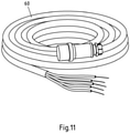
Gemäß einem Ausführungsbeispiel wird vorgeschlagen, dass auf der Ladefläche zumindest ein Anschlusskabel mit einer Steckkupplung an seinem ersten Ende und abisolierten Leitungsenden an seinem zweiten Ende lose gelagert ist. Für den finalen Anschluss des Verteilsystems an dem Teilnehmer wird insbesondere am Hausanschlusskasten oder Netzverknüpfungspunkt des Teilnehmers eine elektrische Verbindung hergestellt. Die Unterschiedlichkeit verschiedener Netzverknüpfungspunkte, insbesondere verschiedener Hausanschlusskästen mit ihren verschiedenen Topologien und Anschlussmöglichkeiten bedingt, dass das Anschlusskabel für den finalen Anschluss an den Teilnehmer auf der einen Seite abisolierte Leitungsenden aufweist. An diese Leitungsenden kann je nach Anforderung des Netzverknüpfungspunkts des Teilnehmers eine Aderendhülse, eine Öse, ein Bolzen oder dergleichen angeschlossen werden, um hierüber eine Verbindung mit dem Netzverknüpfungspunkt des Teilnehmers herzustellen.According to one exemplary embodiment, it is proposed that at least one connection cable with a plug-in coupling at its first end and stripped cable ends at its second end be stored loosely on the loading area. For the final connection of the distribution system to the subscriber, an electrical connection is made in particular at the subscriber's house connection box or network connection point. The difference between different network connection points, in particular different house connection boxes with their different topologies and connection options, means that the connection cable for the final connection to the subscriber has stripped cable ends on one side. Depending on the requirements of the network connection point of the subscriber, a ferrule, an eyelet, a bolt or the like can be connected to these line ends in order to establish a connection with the network connection point of the subscriber.
Wie bereits ausgeführt, ist auf dem Netzverteilsystem ein Verteilkasten vorgesehen. An diesem Verteilkasten sind ein Eingangsfeld und zumindest zwei Ausgangsfelder vorgesehen. Um die Netzersatzanlage oder den Transformator gegenüber dem Verteilsystem abzusichern, können an dem Eingangsfeld Sicherungen vorgesehen werden. Um die Anschlussfelder gegenüber dem Verteilsystem und untereinander abzusichern, können an den jeweiligen Anschlussfeldern Sicherungen vorgesehen sein. Es ist insbesondere vorgesehen, dass an dem Eingangsfeld pro Phase eine Sicherung vorgesehen ist. Auch ist vorgesehen, dass an dem jeweiligen Ausgangsfeld eine Sicherung pro Phase vorgesehen ist.As already explained, a distribution box is provided on the network distribution system. An input field and at least two output fields are provided on this distribution box. To the emergency power system or the transformer opposite To secure the distribution system, fuses can be provided on the input panel. In order to protect the connection panels from the distribution system and from one another, fuses can be provided on the respective connection panels. In particular, provision is made for one fuse per phase to be provided on the input panel. Provision is also made for one fuse per phase to be provided on the respective output field.
Da, wie bereits erwähnt, unterschiedlichste Leistungsanforderungen der Teilnehmer bestehen können, ist für einen mobilen, dynamischen Einsatz im Störfall eine bedarfsgerechte Absicherung von Eingangsfeld und Ausgangsfeldern notwendig. Um dies sicherzustellen, wird vorgeschlagen, dass auf der Ladefläche eine Mehrzahl von für das Eingangsfeld und/oder das Ausgangsfeld dimensionierten Stecksicherungen mit voneinander verschiedenen Sicherungskennlinien gelagert sind. Die Sicherungen sind insbesondere Standartsicherungen, die in Buchsen des Eingangsfeld und/oder der Ausgangsfelder einsteckbar sind. Die Sicherungen können unterschiedliche Sicherungskennlinien haben, insbesondere können diese unterschiedlichste Auslöseströme aufweisen. Je nach Einsatz kann dann die geeignete Sicherung in die Aufnahme des Eingangsfeldes oder eines der Ausgangsfelder eingesteckt werden, sodass der Teilnehmer als auch das Verteilsystem bedarfsgerecht abgesichert werden kann.Since, as already mentioned, the participants can have a wide variety of performance requirements, a needs-based protection of the input field and output fields is necessary for mobile, dynamic use in the event of a fault. In order to ensure this, it is proposed that a plurality of plug-in fuses dimensioned for the input panel and/or the output panel and having different fuse characteristics are stored on the loading area. The fuses are in particular standard fuses that can be plugged into sockets in the input field and/or the output fields. The fuses can have different fuse characteristics, in particular they can have a wide variety of tripping currents. Depending on the application, the appropriate fuse can then be plugged into the receptacle of the input field or one of the output fields, so that the participant and the distribution system can be protected as required.
Gemäß einem Ausführungsbeispiel wird vorgeschlagen, dass auf der Ladefläche zumindest ein mobiler elektrischer Unterverteiler mit zumindest einem Eingang und zumindest zwei Ausgängen lose gelagert ist. Der Eingang als auch die Ausgänge können als Steckkupplung für die Verteilkabel gebildet sein. Die Steckkupplungen sind bevorzugt genormt, insbesondere CEE-Kupplungen. Es kann sinnvoll sein, mit einem ersten Verteilkabel ausgehend von der Anschlusskonsole auf der Ladefläche zu einem Unterverteiler zu verzweigen. Von dort können dann zwei oder mehr Verteilkabel von den Ausgängen abzweigen und zu den Teilnehmern geführt werden.According to one exemplary embodiment, it is proposed that at least one mobile electrical sub-distribution board with at least one input and at least two outputs be loosely mounted on the loading area. The input as well as the outputs can be formed as a plug-in coupling for the distribution cable. The plug-in couplings are preferably standardized, in particular CEE couplings. It can make sense to branch off with a first distribution cable from the connection console on the loading area to a sub-distributor. From there, two or more distribution cables can branch off from the outputs and be routed to the participants.
Es ist insbesondere vorgeschlagen, dass ausgehend von der Ladefläche ein erstes Verteilkabel an dem Netzverteilsystem angeschlossen ist. Am Ende zumindest eines ersten Verteilkabels ist dann das Anschlusskabel mit dem abisolierten Leitungsende angeschlossen, über welches der Netzverknüpfungspunkt des Teilnehmers angeschlossen wird.In particular, it is proposed that, starting from the loading area, a first distribution cable is connected to the network distribution system. At the end of at least one first distribution cable, the connection cable is then connected to the stripped end of the line, via which the network connection point of the subscriber is connected.
Für die Anbindung des Netzverteilsystems an einen Transformator oder eine Netzersatzanlage werden die Eingangsanschlüsse mit Steckkupplungen vorgesehen. Die Eingangsanschlüsse sind einphasig und die Steckkupplungen sind insbesondere hierfür vorgesehene, genormte Steckkupplungen. Für den Fall der Ankopplung an eine Netzersatzanlage, verfügt diese in der Regel über abrollbare Kabel mit Steckkupplungen, die in die Eingangsanschlüsse eingesteckt werden können. Für den Fall einer Ankopplung an einen funktionierenden Transformator kann auf der Ladefläche für jeden Eingangsanschluss separat ein abrollbares Kabel vorgesehen sein.The input connections are provided with plug-in couplings for the connection of the power distribution system to a transformer or an emergency power system. The input connections are single-phase and the plug-in connectors are standardized plug-in connectors specifically designed for this purpose. In the case of connection to an emergency power system, this usually has a rollable cable with plug-in couplings that can be plugged into the input connections. In the event of a connection to a functioning transformer, a rollable cable can be provided separately for each input connection on the loading area.
Die Steckkupplungen an den Eingangsanschlüssen, Anschlusskonsolen, Verteilkabeln und/oder Verteilkästen können insbesondere Spritzwasser geschützt sein. Die Steckkupplungen sind insbesondere genormte Steckkupplungen, beispielsweise CEE-Steckkupplungen mit IPXY mit mindestens X=4 und mindestens Y≥4 nach DIN EN60529 oder ISO20653. Hierdurch kann eine Entstörung auch über mehrere Tage gewährleistet sein, da die Steckkupplungen vor Spritzwasser geschützt sind und somit auch in feuchten Umgebungen und außen dauerhaft elektrisch sicher sind.The plug-in couplings on the input connections, connection consoles, distribution cables and/or distribution boxes can be protected in particular against splashing water. The plug-in couplings are in particular standardized plug-in couplings, for example CEE plug-in couplings with IPXY with at least X=4 and at least Y≥4 according to DIN EN60529 or ISO20653. This means that interference suppression can also be guaranteed for several days, since the plug-in couplings are protected against splashing water and are therefore permanently electrically safe even in damp environments and outdoors.
Das mit den abisolierten Leitungsenden versehene Verteilkabel wird beim Teilnehmer an dessen Netzverknüpfungspunkt elektrisch angeschlossen. Hierzu kann ein Einstecken, Einschrauben, Verschrauben, Festklemmen, Anschrauben oder dergleichen erfolgen. In der Regel ist der Netzverknüpfungspunkt elektrisch abgesichert, beispielsweise durch einen Deckel oder dergleichen. Dies ist insbesondere im Falle eines Hausanschlusskastens der Fall. Um die Kontaktierung für den Entstörfall herzustellen, muss ein solcher Deckel entfernt werden und das Verteilkabel mit dem abisolierten Enden angeschlossen werden. Um einen Berührschutz sicherzustellen, insbesondere für die Dauer der Entstörung, wird vorgeschlagen, dass zumindest eine Isolationshaube für ein Hausanschlusskasten lose auf der Lagerfläche gelagert ist. Der Servicetechniker kann den Hausanschlusskasten öffnen, das Kabel anschließen und anschließend über die Isolationshaube die elektrischen Kontakte berührsicher abdecken.The distribution cable with the stripped cable ends is electrically connected to the subscriber's network connection point. For this purpose, plugging in, screwing in, screwing, clamping, screwing on or the like can take place. As a rule, the network connection point is electrically protected, for example by a cover or the like. This is the case in particular in the case of a house junction box. Such a cover has to be removed in order to establish contact for interference suppression, and that Distribution cables are connected with the stripped ends. In order to ensure protection against accidental contact, in particular for the duration of interference suppression, it is proposed that at least one insulation cover for a house connection box be mounted loosely on the storage area. The service technician can open the house connection box, connect the cable and then cover the electrical contacts with the insulating hood so that they cannot be touched.
Um die Einrichtung auf dem Anhänger vor Umwelteinflüssen zu schützen wird vorgeschlagen, dass der mobile Anhänger feste, die Lagefläche eingrenzende Seitenwände aufweist. Eine bevorzugt hintere Seitenwand kann darüber hinaus schwenkbar sein, insbesondere um eine horizontale Achse, aber auch durch zwei vertikale Achsen schwenkbare hintere Seitenwände. Auch Ein Deckel kann vorgesehen sein, der ebenfalls um eine horizontale Achse schwenkbar ist und an den Seitenwänden befestigt werden kann. Somit können die Komponenten auf dem Anhänger durch die Seitenwände und den Deckel geschützt werden.In order to protect the device on the trailer from environmental influences, it is proposed that the mobile trailer have fixed side walls delimiting the storage area. A preferably rear side wall can also be pivotable, in particular about a horizontal axis, but also rear side walls pivotable by two vertical axes. A cover can also be provided, which can also be pivoted about a horizontal axis and can be fastened to the side walls. Thus, the components on the trailer can be protected by the side walls and the lid.
Ein weiterer vorteilhafter Aspekt kann ein Messgerät sein, welches an dem Eingangsfeld und/oder dem Ausgangsfeld elektrisch kontaktiert ist. Über ein solches Messgerät kann insbesondere Strom und Spannung gemessen werden. Der Strom kann beispielsweise durch an dem Messgerät vorgesehene Rogowski - Spulen über die Kabel gemessen werden. Mit Hilfe des Messgerätes kann der tatsächliche Verbrauch im Störfall bzw. die Leistungsflüsse im Störfall gemessen werden. Das Messgerät kann fernauslesbar sein, sodass während der provisorischen Entstörung stets eine Überwachung der Leistungsflüsse und der Funktionalität des Verteilsystems möglich ist.A further advantageous aspect can be a measuring device which is electrically contacted on the input field and/or the output field. In particular, current and voltage can be measured using such a measuring device. The current can, for example, be measured via the cables by Rogowski coils provided on the measuring device. With the help of the measuring device, the actual consumption in the event of a fault or the power flows in the event of a fault can be measured. The measuring device can be read remotely, so that the power flows and the functionality of the distribution system can always be monitored during the provisional fault clearance.
Für eine Überwachung des Verteilsystems kann auch vorgesehen sein, dass auf dem Anhänger ein Positionsbestimmungsgerät, insbesondere ein GPS-Empfänger vorgesehen ist, der ebenfalls fernauslesbar ist. Hierüber kann die Position des Verteilsystems bestimmt werden.To monitor the distribution system, it can also be provided that a position determination device, in particular a GPS receiver, is provided on the trailer, which can also be read out remotely. This can be used to determine the position of the distribution system.
Nachfolgend wird der Gegenstand anhand einer Ausführungsbeispiele zeigenden Zeichnung näher erläutert. In der Zeichnung zeigen:
- Fig. 1
- einen schematischen Aufbau eines provisorischen Verteilnetzes, welches mit einem gegenständlichen Netzverteilsystem aufgebaut werden kann;
- Fig. 2
- eine Topologie eines aufgebauten Verteilnetzes gemäß einem Ausführungsbeispiel;
- Fig. 3
- einen gegenständlichen Anhänger gemäß einem Ausführungsbeispiel;
- Fig. 4
- einen bestückten mobilen Anhänger gemäß einem Ausführungsbeispiel;
- Fig. 5
- ein Anschlussfeld gemäß einem Ausführungsbeispiel;
- Fig. 6
- einen Verteilkasten gemäß einem Ausführungsbeispiel;
- Fig. 7
- eine Anschlusskonsole gemäß einem Ausführungsbeispiel;
- Fig. 8
- lose gelagerte Verteilkabel gemäß einem Ausführungsbeispiel;
- Fig. 9
- Kabeltrommeln gemäß einem Ausführungsbeispiel;
- Fig. 10
- einen Verteilkasten gemäß einem Ausführungsbeispiel;
- Fig. 11
- ein Anschlusskabel gemäß einem Ausführungsbeispiel.
- 1
- a schematic structure of a provisional distribution network, which can be set up with a physical network distribution system;
- 2
- a topology of an established distribution network according to an embodiment;
- 3
- a physical tag according to one embodiment;
- 4
- a populated mobile trailer according to one embodiment;
- figure 5
- a connector pad according to an embodiment;
- 6
- a junction box according to an embodiment;
- 7
- a connection panel according to an embodiment;
- 8
- loosely stored distribution cables according to an embodiment;
- 9
- Cable reels according to an embodiment;
- 10
- a junction box according to an embodiment;
- 11
- a connection cable according to an embodiment.
Ein System 2 kann mit einer Netzersatzanlage 8 elektrisch verbunden sein, wie nachfolgend noch gezeigt werden wird. Ein System 2 kann alternativ auch mit einem Netzverknüpfungspunkt 10 verbunden sein. Beide Anordnungen, sowohl mit Netzersatzanlage 8 als auch mit Netzverknüpfungspunkt 10 liegen an den Eingangsanschlüssen der Systeme 2 an. Ausgehend von den Systemen 2 können Teilnehmer 12 über Verteilkabel 14 mit dem elektrischen Versorgungsnetz notversorgt werden. Die Verkabelung ausgehend von den Systemen 2 hin zu den Teilnehmern 12 erfolgt über eine Vielzahl unterschiedlicher Verteilkabel 14.A
Eine mögliche Topologie ist in
Für die Verteilung der elektrischen Energie zu den Teilnehmern 12 zweigen Verteilkabel 14 von dem System 2 ab bzw. sie werden manuell oberirdisch verlegt. Die Verteilkabel 14 können auf dem Weg vom System 2 zum Teilnehmer 12 auch verlängert werden, indem sie über Steckkupplungen 16 miteinander verbunden werden. Ferner können Unterverteiler 18 vorgesehen sein, die ebenfalls über Steckkupplungen 16 mit den Verteilkabeln verbunden werden.
Ausgehend von den Unterverteilern 18 oder unmittelbar von einer Steckkupplung 16 kann ein Anschlusskabel 20 bis an den Netzverknüpfungspunkt des Teilnehmers geführt werden. Das Anschlusskabel 20 kann auf der einen Seite eine Steckkupplung aufweisen 16, mit der dieses mit dem Verteilkabel 14 verbunden werden kann. Andererseits kann das Anschlusskabel 20 auf der gegenüberliegenden Seite freigelegte Leitungen aufweisen, über die ein elektrischer Anschluss an den Hausverteilkasten oder einen sonstigen Netzverknüpfungspunkt des Teilnehmers 12 möglich ist.Starting from the sub-distributors 18 or directly from a plug-in
Im Störungsfall wird das System 2 sowie die Netzersatzanlage 8 an den Standort verlegt. Anschließend werden die Anschlusskabel 20 mit den Hausanschlusskästen verbunden und über die Steckkupplungen 16 und die Verteilkabel 14 werden die so angeschlossenen Hausanschlusskästen mit den Ausgangsanschlüssen des Systems 2 verbunden. Gleichzeitig oder nachfolgend erfolgt eine Verbindung des Systems 2 mit der Netzersatzanlage. Im System 2 wird ein Verteilkasten mit den entsprechenden Sicherungen bestückt. Nach vollständiger Verkabelung wird zunächst die Netzersatzanlage 8 eingeschaltet und anschließend die Sicherung im Verteilkasten des Systems 2 eingeschaltet, sodass das provisorische Versorgungsnetz unter Spannung gesetzt wird und die Teilnehmer 12 mit elektrischem Strom versorgt sind.In the event of a fault,
Das System 2 ist auf einem Anhänger 4, wie in der
In der
Der Anschlusskasten 40 ist beispielhaft in
Der Anschlusskasten 40 kann ein Standard Anschlusskasten sein mit einem Gehäuse und einer Tür zum Öffnen. Eingangsseitig kann der Anschlusskasten 40 über ein Eingangsfeld 42 verfügen. Die Kabel 38 sind jeweils mit einem der Anschlüsse des Eingangsfelds 42 verbunden. Ausgehend von dem Eingangsfeld 42 wird jeweils eine Sammelschiene horizontal zu Ausgangsfeldern 44 geführt. An den Anschlüssen des Eingangsfelds 42 als auch den Ausgangsfeldern 44 kann pro Phase und pro Feld jeweils eine Aufnahme für eine Stecksicherung vorgesehen werden. Ausgehend von den Sicherungen der Ausgangsfelder 40 werden die einzelnen Phasen auf dreiphasige Ausgangsanschlüsse 46 geführt. In dem gezeigten Beispiel hat der Anschlusskasten 40 ein Eingangsfeld 42 und sechs Ausgangsfelder 44 und somit sechs Ausgangsanschlüsse 46. Die Ausgangsanschlüsse 46 sind mit den Phasen L1, L2, L3 über die Ausgangsfelder 44 verbunden. Über Sammelschienen sind die Ausgangsanschlüsse darüber hinaus mit dem Neutralleiter und dem Erdungsleiter verbunden. Im Bereitschaftsmodus, das heißt, wenn noch keine Notstromversorgung etabliert ist, sind die Sicherungsaufnahmen von Eingangsfeld 42 und der Ausgangsfelder 44 unbestückt, sind jedoch so eingerichtet, dass sie mit Standard Sicherungen bestückt werden, indem diese eingesteckt werden.The
Die Ausgangsanschlüsse 46 sind auf dem System 4 mit Anschlusskonsolen 50 verbunden, wie
Neben diesen fest auf der Ladefläche 22 montierten Komponenten ist auf der Ladefläche 22 Stauraum für eine lose Lagerung von weiteren Komponenten. Zunächst ist es notwendig, nach dem Verdrahten die Sicherungen in den Anschlusskasten 40 einzusetzen. Zur Verwahrung von Sicherungen verschiedenster Sicherungskennlinien ist eine Verwahrbox 52 auf der Ladefläche 22 vorgesehen. Hierin können die Sicherungen, bevorzugt sortiert nach Sicherungskennlinie oder Nennwert, gelagert werden.In addition to these components permanently mounted on the
Neben der Sicherung ist es notwendig, ausgehend von den Anschlusskonsolen 50 Verteilkabel anzuschließen. Diese Verteilkabel können in einer Box 54 verwahrt werden. Verteilkabel sind insbesondere Standard Kabel 14, wie sie in
Um die Verteilkabel 14 abzurollen, entweder unmittelbar von der Ladefläche 22 oder an einen entfernten Ort, sind Kabeltrommeln 56, wie in der
Darüber hinaus kann ein Unterverteiler 58, wie in der
Zum abschließenden Anschluss eines Verteilkabels an einen Hausverteilkasten, können Anschlusskabel 60, wie in
Zusätzlich, aber nicht gezeigt, kann auf der Ladefläche 22 ein Positionsmodul montiert sein, beispielsweise ein GPS-Modul, ein Glonass-Modul, ein Galileo-Modul oder dergleichen, welches insbesondere fernauslesbar ist und die Position des Systems 2 bestimmbar macht.In addition, but not shown, a position module can be mounted on the
Darüber hinaus kann an dem Eingangsfeld 42 und/oder eine oder mehrere Phasen des Ausgangsfeldes 44 ein nicht gezeigtes Messgerät angeschlossen werden, mit welchem im Notbetrieb die Leistungsflüsse auf den einzelnen Phasen und/oder den einzelnen Ausgangsanschlüssen 46 und/oder den Eingangsanschlüssen messbar sind. Hierdurch kann eine Überwachung und Bewertung des Notsystems erfolgen.In addition, a measuring device (not shown) can be connected to the
Auch können auf der Ladefläche 22 ein oder mehrere Abdeckhauben 62 vorgesehen sein, die zum Schutz eines geöffneten Hausanschlusskastens oder eines sonstigen Netzverknüpfungspunkts an einem Teilnehmer dienen.One or
Im Störungsfall wird das System 2 mit der Anhängerkupplung 2 an eine Zugmaschine 6 gehängt und zu der Störung verlegt. Ist eine Netzersatzanlage 8 notwendig, kann diese ebenfalls dorthin verlegt werden.In the event of a fault, the
Die Anschlusskabel 60 werden an den Hausanschlusskästen der Teilnehmer 12 elektrisch verbunden, indem zunächst das gestörte, bisher am Hausanschlusskasten angeschlossene Netz abgetrennt wird und anschließend die einzelnen Phasen, der Neutralleiter und der Erdungsleiter aufgelegt wird. Anschließend werden die Anschlusskabel 60 optional über die Unterverteilung 58 und über zumindest ein Verteilkabel 14 mit den Anschlusskonsolen 40 verbunden. Eingangsseitig wird die Netzersatzanlage 8 über die Kabel 38 mit dem Eingangsfeld 42 des Anschlusskastens 40 verbunden. Im Eingangsfeld 42 als auch in den benötigten Ausgangsfeldern 44 werden bedarfsgerecht Sicherungen eingesteckt und umgelegt. Hiernach ist das Netz provisorisch aufgebaut und die Teilnehmer 12 mit Strom versorgt.The
- 22
- Systemsystem
- 44
- Anhängerfollower
- 66
- Zugmaschinetractor
- 88th
- Netzersatzanlageemergency power system
- 1010
- Netzverknüpfungspunktnetwork connection point
- 1212
- TeilnehmerAttendees
- 1414
- Verteilkabeldistribution cable
- 1616
- Steckkupplungplug-in coupling
- 1818
- Unterverteilungsub-distribution
- 2020
- Anschlusskabelconnection cable
- 2222
- Ladeflächetruck bed
- 24, 2624, 26
- SeitenwandSide wall
- 2828
- Deckellid
- 3030
- Deichseldrawbar
- 3232
- Anhängerkupplungtrailer hitch
- 3434
- Anschlussfeldconnector panel
- 3636
- Kabeltrommelcable reel
- 3838
- Kabelcable
- 4040
- Anschlusskastenjunction box
- 4242
- Eingangsfeldinput field
- 4444
- Ausgangsfeldexit field
- 4646
- Ausgangsanschlussoutput port
- 5050
- Anschlusskonsoleconnection console
- 5252
- Aufbewahrungsboxstorage box
- 5454
- Aufbewahrungskastenstorage box
- 5656
- Kabeltrommelcable reel
- 5858
- Unterverteilungsub-distribution
- 6060
- Anschlusskabelconnection cable
- 6262
- Sicherungfuse
Claims (12)
dadurch gekennzeichnet,
characterized,
dadurch gekennzeichnet,
characterized,
dadurch gekennzeichnet,
characterized,
dadurch gekennzeichnet,
characterized,
dadurch gekennzeichnet,
characterized,
dadurch gekennzeichnet,
characterized,
dadurch gekennzeichnet,
characterized,
dadurch gekennzeichnet,
characterized,
dadurch gekennzeichnet,
characterized,
dadurch gekennzeichnet,
characterized,
dadurch gekennzeichnet,
characterized,
Applications Claiming Priority (1)
| Application Number | Priority Date | Filing Date | Title |
|---|---|---|---|
| DE102020123259.4A DE102020123259A1 (en) | 2020-09-07 | 2020-09-07 | Mobile network distribution system |
Publications (1)
| Publication Number | Publication Date |
|---|---|
| EP3965247A1 true EP3965247A1 (en) | 2022-03-09 |
Family
ID=77499610
Family Applications (1)
| Application Number | Title | Priority Date | Filing Date |
|---|---|---|---|
| EP21190484.2A Pending EP3965247A1 (en) | 2020-09-07 | 2021-08-10 | Mobile network distribution system |
Country Status (2)
| Country | Link |
|---|---|
| EP (1) | EP3965247A1 (en) |
| DE (1) | DE102020123259A1 (en) |
Citations (2)
| Publication number | Priority date | Publication date | Assignee | Title |
|---|---|---|---|---|
| US20110188167A1 (en) * | 2010-01-30 | 2011-08-04 | Jack Jumper, Llc | Portable transformer with safety interlock |
| CN203553683U (en) * | 2013-11-27 | 2014-04-16 | 国家电网公司 | Mobile temporary distribution and transformation wagon |
-
2020
- 2020-09-07 DE DE102020123259.4A patent/DE102020123259A1/en active Pending
-
2021
- 2021-08-10 EP EP21190484.2A patent/EP3965247A1/en active Pending
Patent Citations (2)
| Publication number | Priority date | Publication date | Assignee | Title |
|---|---|---|---|---|
| US20110188167A1 (en) * | 2010-01-30 | 2011-08-04 | Jack Jumper, Llc | Portable transformer with safety interlock |
| CN203553683U (en) * | 2013-11-27 | 2014-04-16 | 国家电网公司 | Mobile temporary distribution and transformation wagon |
Non-Patent Citations (1)
| Title |
|---|
| NORDWEST HANDEL AG ROBERT-SCHUMAN-STR. 17 D-44263 DORTMUND: "Der Baukatalog", 30 April 2017 (2017-04-30), XP055586057, Retrieved from the Internet <URL:https://www.kicherer.de/fileadmin/user_upload/bilder/pdf/Kicherer_Der_Baukatalog_2017.pdf> [retrieved on 20190507] * |
Also Published As
| Publication number | Publication date |
|---|---|
| DE102020123259A1 (en) | 2022-03-10 |
Similar Documents
| Publication | Publication Date | Title |
|---|---|---|
| US6696925B1 (en) | Electrical revenue meter and instrument transformers mobile station | |
| EP1864361B1 (en) | Switchgear cabinet assembly or rack assembly | |
| DE102017011374A1 (en) | Protective device for low-voltage systems with integrated measuring electronics | |
| EP3829010A1 (en) | Adapter device for busbar systems | |
| DE102015105152A1 (en) | Arrangement and method for reducing unbalanced load in a three-phase distribution network | |
| EP2978091B1 (en) | Method for the transmission of electric power | |
| DE102013106216B4 (en) | Measuring device for current measurement | |
| DE102017011373A1 (en) | Measuring and control electronics for low-voltage switchgear | |
| EP3965247A1 (en) | Mobile network distribution system | |
| DE202014100207U1 (en) | Coupler for medium voltage powerline communication | |
| DE69834554T2 (en) | ELECTRIC SCHOOL EQUIPMENT | |
| DE4210657C2 (en) | Plug-in low-voltage switchgear for the supply or distribution of electrical energy | |
| DE2554619A1 (en) | Three-phase supply distribution socket - has plug, cable and socket block with one three-phase and three single-phase sockets | |
| DE1591204A1 (en) | Branch for community antenna | |
| WO2018153433A1 (en) | Modular multilevel power converter | |
| DE102006054940A1 (en) | Switchgear with redundancy | |
| DE3723991C2 (en) | ||
| WO2006105878A1 (en) | Electrical switchgear | |
| DE102021111396B4 (en) | Adapter for a busbar support | |
| DE60133580T2 (en) | ELECTRICALLY CONDUCTIVE ELEMENT TO REVERSE ELECTRICITY SUPPLY | |
| DE102004006851B4 (en) | Control cabinet or rack arrangement | |
| DE3328785A1 (en) | Bushing insulator for a bulkhead wall in an installation cabinet for medium-voltage switching and distribution installations | |
| EP0582954B2 (en) | Wiring in cable ducts | |
| DE102015218486A1 (en) | Charging device for an electric vehicle | |
| DE112020000655T5 (en) | Electric power cable |
Legal Events
| Date | Code | Title | Description |
|---|---|---|---|
| PUAI | Public reference made under article 153(3) epc to a published international application that has entered the european phase |
Free format text: ORIGINAL CODE: 0009012 |
|
| STAA | Information on the status of an ep patent application or granted ep patent |
Free format text: STATUS: THE APPLICATION HAS BEEN PUBLISHED |
|
| AK | Designated contracting states |
Kind code of ref document: A1 Designated state(s): AL AT BE BG CH CY CZ DE DK EE ES FI FR GB GR HR HU IE IS IT LI LT LU LV MC MK MT NL NO PL PT RO RS SE SI SK SM TR |
|
| STAA | Information on the status of an ep patent application or granted ep patent |
Free format text: STATUS: REQUEST FOR EXAMINATION WAS MADE |
|
| 17P | Request for examination filed |
Effective date: 20220906 |
|
| RBV | Designated contracting states (corrected) |
Designated state(s): AL AT BE BG CH CY CZ DE DK EE ES FI FR GB GR HR HU IE IS IT LI LT LU LV MC MK MT NL NO PL PT RO RS SE SI SK SM TR |