EP3960075A1 - Systems and methods for tracking positions between imaging modalities and transforming a displayed three-dimensional image corresponding to a position and orientation of a probe - Google Patents
Systems and methods for tracking positions between imaging modalities and transforming a displayed three-dimensional image corresponding to a position and orientation of a probe Download PDFInfo
- Publication number
- EP3960075A1 EP3960075A1 EP21203277.5A EP21203277A EP3960075A1 EP 3960075 A1 EP3960075 A1 EP 3960075A1 EP 21203277 A EP21203277 A EP 21203277A EP 3960075 A1 EP3960075 A1 EP 3960075A1
- Authority
- EP
- European Patent Office
- Prior art keywords
- ordinate
- space
- landmark
- ultrasound
- probe
- Prior art date
- Legal status (The legal status is an assumption and is not a legal conclusion. Google has not performed a legal analysis and makes no representation as to the accuracy of the status listed.)
- Pending
Links
- 239000000523 sample Substances 0.000 title claims abstract description 174
- 238000000034 method Methods 0.000 title claims abstract description 110
- 238000003384 imaging method Methods 0.000 title claims abstract description 74
- 230000001131 transforming effect Effects 0.000 title claims abstract description 26
- 238000002604 ultrasonography Methods 0.000 claims description 233
- 239000011159 matrix material Substances 0.000 claims description 81
- 210000001519 tissue Anatomy 0.000 claims description 60
- 230000009466 transformation Effects 0.000 claims description 49
- 210000000988 bone and bone Anatomy 0.000 claims description 7
- 210000002435 tendon Anatomy 0.000 claims description 6
- 210000001367 artery Anatomy 0.000 claims description 4
- 239000003550 marker Substances 0.000 claims description 4
- 210000002445 nipple Anatomy 0.000 claims description 4
- 210000003462 vein Anatomy 0.000 claims description 4
- 238000002595 magnetic resonance imaging Methods 0.000 description 166
- 239000013598 vector Substances 0.000 description 71
- 238000012285 ultrasound imaging Methods 0.000 description 50
- 238000004891 communication Methods 0.000 description 47
- 230000003287 optical effect Effects 0.000 description 21
- 238000012937 correction Methods 0.000 description 13
- 230000008569 process Effects 0.000 description 10
- 238000012545 processing Methods 0.000 description 8
- 238000002059 diagnostic imaging Methods 0.000 description 7
- 238000004458 analytical method Methods 0.000 description 6
- 230000008901 benefit Effects 0.000 description 6
- 230000006870 function Effects 0.000 description 5
- 230000005540 biological transmission Effects 0.000 description 4
- 238000001574 biopsy Methods 0.000 description 4
- 238000004590 computer program Methods 0.000 description 4
- 230000005284 excitation Effects 0.000 description 3
- 238000013519 translation Methods 0.000 description 3
- 230000000007 visual effect Effects 0.000 description 3
- PXFBZOLANLWPMH-UHFFFAOYSA-N 16-Epiaffinine Natural products C1C(C2=CC=CC=C2N2)=C2C(=O)CC2C(=CC)CN(C)C1C2CO PXFBZOLANLWPMH-UHFFFAOYSA-N 0.000 description 2
- 206010028980 Neoplasm Diseases 0.000 description 2
- 241001422033 Thestylus Species 0.000 description 2
- 238000002591 computed tomography Methods 0.000 description 2
- 238000013500 data storage Methods 0.000 description 2
- 238000013178 mathematical model Methods 0.000 description 2
- 230000007246 mechanism Effects 0.000 description 2
- 238000012014 optical coherence tomography Methods 0.000 description 2
- 238000002600 positron emission tomography Methods 0.000 description 2
- 210000004872 soft tissue Anatomy 0.000 description 2
- 210000003484 anatomy Anatomy 0.000 description 1
- 201000011510 cancer Diseases 0.000 description 1
- 230000001413 cellular effect Effects 0.000 description 1
- 238000001514 detection method Methods 0.000 description 1
- 230000000694 effects Effects 0.000 description 1
- 238000001839 endoscopy Methods 0.000 description 1
- 239000000835 fiber Substances 0.000 description 1
- 238000002594 fluoroscopy Methods 0.000 description 1
- 210000004884 grey matter Anatomy 0.000 description 1
- 125000004435 hydrogen atom Chemical group [H]* 0.000 description 1
- 210000003734 kidney Anatomy 0.000 description 1
- 210000004185 liver Anatomy 0.000 description 1
- 210000004072 lung Anatomy 0.000 description 1
- 238000005259 measurement Methods 0.000 description 1
- 238000012986 modification Methods 0.000 description 1
- 230000004048 modification Effects 0.000 description 1
- 230000006855 networking Effects 0.000 description 1
- 230000000149 penetrating effect Effects 0.000 description 1
- 230000035515 penetration Effects 0.000 description 1
- 230000036316 preload Effects 0.000 description 1
- 238000002603 single-photon emission computed tomography Methods 0.000 description 1
- 230000004083 survival effect Effects 0.000 description 1
- 238000012360 testing method Methods 0.000 description 1
- 238000007794 visualization technique Methods 0.000 description 1
- XLYOFNOQVPJJNP-UHFFFAOYSA-N water Substances O XLYOFNOQVPJJNP-UHFFFAOYSA-N 0.000 description 1
- 210000004885 white matter Anatomy 0.000 description 1
Images


Classifications
-
- G—PHYSICS
- G06—COMPUTING; CALCULATING OR COUNTING
- G06T—IMAGE DATA PROCESSING OR GENERATION, IN GENERAL
- G06T15/00—3D [Three Dimensional] image rendering
- G06T15/10—Geometric effects
- G06T15/20—Perspective computation
-
- A—HUMAN NECESSITIES
- A61—MEDICAL OR VETERINARY SCIENCE; HYGIENE
- A61B—DIAGNOSIS; SURGERY; IDENTIFICATION
- A61B8/00—Diagnosis using ultrasonic, sonic or infrasonic waves
- A61B8/42—Details of probe positioning or probe attachment to the patient
- A61B8/4245—Details of probe positioning or probe attachment to the patient involving determining the position of the probe, e.g. with respect to an external reference frame or to the patient
-
- A—HUMAN NECESSITIES
- A61—MEDICAL OR VETERINARY SCIENCE; HYGIENE
- A61B—DIAGNOSIS; SURGERY; IDENTIFICATION
- A61B8/00—Diagnosis using ultrasonic, sonic or infrasonic waves
- A61B8/42—Details of probe positioning or probe attachment to the patient
- A61B8/4272—Details of probe positioning or probe attachment to the patient involving the acoustic interface between the transducer and the tissue
- A61B8/4281—Details of probe positioning or probe attachment to the patient involving the acoustic interface between the transducer and the tissue characterised by sound-transmitting media or devices for coupling the transducer to the tissue
-
- A—HUMAN NECESSITIES
- A61—MEDICAL OR VETERINARY SCIENCE; HYGIENE
- A61B—DIAGNOSIS; SURGERY; IDENTIFICATION
- A61B8/00—Diagnosis using ultrasonic, sonic or infrasonic waves
- A61B8/44—Constructional features of the ultrasonic, sonic or infrasonic diagnostic device
- A61B8/4444—Constructional features of the ultrasonic, sonic or infrasonic diagnostic device related to the probe
- A61B8/4455—Features of the external shape of the probe, e.g. ergonomic aspects
-
- A—HUMAN NECESSITIES
- A61—MEDICAL OR VETERINARY SCIENCE; HYGIENE
- A61B—DIAGNOSIS; SURGERY; IDENTIFICATION
- A61B8/00—Diagnosis using ultrasonic, sonic or infrasonic waves
- A61B8/46—Ultrasonic, sonic or infrasonic diagnostic devices with special arrangements for interfacing with the operator or the patient
- A61B8/461—Displaying means of special interest
- A61B8/463—Displaying means of special interest characterised by displaying multiple images or images and diagnostic data on one display
-
- A—HUMAN NECESSITIES
- A61—MEDICAL OR VETERINARY SCIENCE; HYGIENE
- A61B—DIAGNOSIS; SURGERY; IDENTIFICATION
- A61B8/00—Diagnosis using ultrasonic, sonic or infrasonic waves
- A61B8/46—Ultrasonic, sonic or infrasonic diagnostic devices with special arrangements for interfacing with the operator or the patient
- A61B8/461—Displaying means of special interest
- A61B8/465—Displaying means of special interest adapted to display user selection data, e.g. icons or menus
-
- A—HUMAN NECESSITIES
- A61—MEDICAL OR VETERINARY SCIENCE; HYGIENE
- A61B—DIAGNOSIS; SURGERY; IDENTIFICATION
- A61B8/00—Diagnosis using ultrasonic, sonic or infrasonic waves
- A61B8/46—Ultrasonic, sonic or infrasonic diagnostic devices with special arrangements for interfacing with the operator or the patient
- A61B8/461—Displaying means of special interest
- A61B8/466—Displaying means of special interest adapted to display 3D data
-
- A—HUMAN NECESSITIES
- A61—MEDICAL OR VETERINARY SCIENCE; HYGIENE
- A61B—DIAGNOSIS; SURGERY; IDENTIFICATION
- A61B8/00—Diagnosis using ultrasonic, sonic or infrasonic waves
- A61B8/52—Devices using data or image processing specially adapted for diagnosis using ultrasonic, sonic or infrasonic waves
- A61B8/5215—Devices using data or image processing specially adapted for diagnosis using ultrasonic, sonic or infrasonic waves involving processing of medical diagnostic data
- A61B8/5238—Devices using data or image processing specially adapted for diagnosis using ultrasonic, sonic or infrasonic waves involving processing of medical diagnostic data for combining image data of patient, e.g. merging several images from different acquisition modes into one image
-
- G06T3/08—
-
- G—PHYSICS
- G06—COMPUTING; CALCULATING OR COUNTING
- G06T—IMAGE DATA PROCESSING OR GENERATION, IN GENERAL
- G06T3/00—Geometric image transformation in the plane of the image
- G06T3/60—Rotation of a whole image or part thereof
-
- G—PHYSICS
- G06—COMPUTING; CALCULATING OR COUNTING
- G06T—IMAGE DATA PROCESSING OR GENERATION, IN GENERAL
- G06T7/00—Image analysis
- G06T7/0002—Inspection of images, e.g. flaw detection
- G06T7/0012—Biomedical image inspection
-
- G—PHYSICS
- G06—COMPUTING; CALCULATING OR COUNTING
- G06T—IMAGE DATA PROCESSING OR GENERATION, IN GENERAL
- G06T7/00—Image analysis
- G06T7/10—Segmentation; Edge detection
- G06T7/13—Edge detection
-
- G—PHYSICS
- G06—COMPUTING; CALCULATING OR COUNTING
- G06T—IMAGE DATA PROCESSING OR GENERATION, IN GENERAL
- G06T7/00—Image analysis
- G06T7/70—Determining position or orientation of objects or cameras
- G06T7/73—Determining position or orientation of objects or cameras using feature-based methods
-
- A—HUMAN NECESSITIES
- A61—MEDICAL OR VETERINARY SCIENCE; HYGIENE
- A61B—DIAGNOSIS; SURGERY; IDENTIFICATION
- A61B8/00—Diagnosis using ultrasonic, sonic or infrasonic waves
- A61B8/13—Tomography
-
- G—PHYSICS
- G06—COMPUTING; CALCULATING OR COUNTING
- G06T—IMAGE DATA PROCESSING OR GENERATION, IN GENERAL
- G06T2207/00—Indexing scheme for image analysis or image enhancement
- G06T2207/10—Image acquisition modality
- G06T2207/10132—Ultrasound image
- G06T2207/10136—3D ultrasound image
Definitions
- This invention relates to the field of medical imaging and more specifically relates to dynamically transforming a displayed three dimensional medical image of a tissue.
- Medical imaging devices provide non- invasive methods to visualize the internal structure of a patient. Such non-invasive visualization methods can be helpful in treating patients for various ailments. For example, the early detection of cancer in a patient can be important in treating that patient. For most cancers, when detected at an early stage, the survival probability of the patient can increase.
- any displayed three-dimensional image can be dynamically transformed using the systems and methods described herein, for example a three-dimensional CT image, three-dimensional optical coherence tomography image, or other three-dimensional medical image of a tissue of a patient such as single photon emission computed tomography or positron emission tomography.
- any medical imaging method having a field of view can be used in the systems and methods described herein, including OCT (optical) sensors and PET detectors.
- Magnetic resonance imaging is one such non-invasive medical imaging technique which uses magnetic fields to image tissue of a patient.
- a patient is placed inside a powerful uniform magnetic field of an MRI scanner, which can align the magnetic moments of protons in the tissue (typically hydrogen protons of water molecules in the tissue) in the direction of the field, precessing about the field at their Larmor frequency.
- An excitation magnetic field typically orthogonal to the main magnetic field
- the protons emit a photon that can be detected and processed to form an MRI image of the tissue.
- Ultrasound imaging uses sound waves, typically produced by piezoelectric transducers to image a tissue in a patient.
- the ultrasound probe focuses the sound waves, typically producing an arc-shaped sound wave which travels into the body and is partially reflected from the layers between different tissues in the patient.
- the reflected sound wave is detected by the transducer and converted into electrical signals that can be processed by the ultrasound scanner to form an ultrasound image of the tissue.
- ultrasound imaging and ultrasound imaging has certain advantages and certain drawbacks.
- ultrasound tends to provide improved imaging of tendon structure in a patient over the images of the same tendon structure provided by an MRI.
- Ultrasound tends to provide superior spatial resolution over similar images obtained by an MRI machine.
- MRI imaging tends to provide superior soft-tissue contrast resolution as compared to ultrasound images, typical MRI images tending to allow individual structures such as a lung, liver, kidney, bowel, and gray and white matter to be distinguished. Additionally, ultrasound provides a smaller field-of-view as compared to MRI imaging, and the resolution of ultrasound images tends to be restricted by the sound wave penetration through soft tissues and bone. For example, ultrasound imaging has difficulty penetrating bone and thus typically only sees the outer surface of bone structure and not what lies within.
- ultrasound imaging provides real-time feedback.
- an ultrasound technician can position the ultrasound transducer directly on a patent in a first position and view the ultrasound image in real time. Subsequently, the technician can move the ultrasound transducer to a second, perhaps more desirable position, to view the new ultrasound image, again in real time.
- This ability to adjust the position of the transducer, while viewing the ultrasound image in real time provides the technician the ability adjust the ultrasound image until they are satisfied with the displayed image.
- Real-time imaging can be helpful during biopsy, where the ultrasound transducer can be used to view an image of the biopsy tool in real-time, for example a biopsy needle as it is inserted in the tissue.
- MRI imaging or any three-dimensional medical image such as single positron emission computed tomography, computed tomography, positron emission tomography, fluoroscopy or endoscopy
- ultrasound imaging to view an image of a tissue in a patient simultaneously using multiple imaging techniques.
- MRI imaging or any three-dimensional medical image such as single positron emission computed tomography, computed tomography, positron emission tomography, fluoroscopy or endoscopy
- ultrasound imaging By tracking the movement of an ultrasound probe and dynamically adjusting a MRI image (or any three-dimensional medical image), for example, to show the slice of the tissue in the MRI image currently being imaged by the ultrasound imaging device, a user is provided with two images of the same tissue at the same time, taking advantage of the benefits of multiple imaging techniques.
- a method of co-registering a first co-ordinate space with a second co-ordinate space comprising: determining a 4 ⁇ 4 transformation matrix capable of transforming a co-ordinate in the first co-ordinate space to the second co-ordinate space, the transformation matrix having a rotational component and a translational component.
- the translational component is determined by: selecting a landmark in the first co-ordinate space; locating the landmark in the second co-ordinate space; determining the position of the landmark in the second co-ordinate space; and determining the translational component being the relative difference between the position of the landmark in the first co-ordinate space and the position of the landmark in the second coordinate space.
- the rotational component is determined by: selecting a plane; determining the orientation of the selected plane in the first co-ordinate space; positioning a probe having a plurality of transmitters removably connected thereto, the transmitters operable to determine the position and orientation of the probe in the second co-ordinate space; determining the rotational component being the relative rotational differences between the orientation the probe in the second co-ordinate space with the selected plane in the first co-ordinate space.
- an apparatus for transforming a displayed three-dimensional image corresponding to a position and orientation of a field of view of an imaging probe comprising: a three dimensional image of a tissue having a first co-ordinate space; a tracking module in communication with a tracking system capable of tracking the positions of a plurality of transmitters removably connected to the imaging probe; a calibration module capable of calibrating the field of view of the imaging probe relative to the tracked positions of the plurality of transmitters in the second coordinate space; a transformation module capable of co-registering the first and second coordinate spaces; an image processing module capable of transforming the position and orientation of the field of view in the second co-ordinate space to the first co-ordinate space; and a display capable of displaying the three-dimensional image to correspond to the transformed position and orientation of the field of view.
- the apparatus may further comprise an error correction capable of checking for errors in calibrating the field of view.
- a computer-readable medium having instructions thereon for causing a processor to execute the instructions, the instructions adapted to be executed to implement a method for transforming a displayed three-dimensional image corresponding to a position and orientation of a field of view of an imaging probe, the method comprising: displaying a three dimensional image of a tissue having a first co-ordinate space; calibrating the field of view of the imaging probe in a second co-ordinate space to a plurality of transmitters removably connected to the imaging probe, the transmitters operable to determine the position and orientation of the field of view relative to the positions of the transmitters in the second coordinate space; co-registering the first and second co-ordinate spaces; transforming the position and orientation of the field of view in the second co-ordinate space to the first coordinate space; and displaying the three-dimensional image to correspond to the transformed position and orientation of the field of view.
- a method for determining the co-ordinates of a landmark visible in a field of view of an ultrasound image in a coordinate space comprising: calibrating the field of view of the ultrasound probe with a plurality of transmitters removably connected to the imaging probe, the transmitters operable to determine the position and orientation of the field of view relative to the positions of the transmitters in the co-ordinate space; determining a calibration matrix that relates a transducer co-ordinate frame in the co-ordinate space to a transmitter co-ordinate frame in the co-ordinate space, wherein the transducer co-ordinate frame has an origin (O) at a midpoint of a face of the transducer; determining the coordinates of the landmark in the field of view relative to a midpoint of a line formed between the upper right corner of the field of view and an upper left corner of the field of view by: determining an axial distance to the landmark in the field of view, wherein the axial distance is the perpendicular distance from the landmark to the
- the method may further comprise offsetting the axial distance to compensate for the curvilinear shape of the transducer.
- systems and methods are provide a means of registering an ultrasound image space with a tracked coordinate space, in some embodiments the co-ordinate system of an optical or magnetic tracking system.
- systems and methods are provided that can be used with any ultrasound transducer with a scan head that has four identifiable corners (including linear, curvilinear, array and phased array transducers).
- systems and methods are provided that can perform platform independent co-registration between two imaging modalities, such as ultrasound and MRI, without communications between them.
- systems and methods described herein can reformat three-dimensional image data to match real-time two-dimensional ultrasound data without direct communication with the ultrasound machine.
- systems and methods are provided that can be used with any six degree of freedom (6-DOF) positional tracking system, such as optical tracking systems, radiofrequency magnetic tracking systems, mechanical linkage tracking systems and fiber optic positioning devices.
- 6-DOF six degree of freedom
- a method for transforming a displayed three-dimensional image corresponding to a position and orientation of a field of view of an imaging probe comprising displaying a three dimensional image of a tissue having a first co-ordinate space; calibrating the field of view of the imaging probe in a second co-ordinate space to a plurality of transmitters removably connected to the imaging probe, the transmitters operable to determine the position and orientation of the field of view relative to the positions of the transmitters in the second co-ordinate space; co-registering the first and second co-ordinate spaces; transforming the position and orientation of the field of view in the second co-ordinate space to the first co-ordinate space; and displaying the three-dimensional image to correspond to the transformed position and orientation of the field of view.
- the calibrating of the field of view of the imaging probe can comprise positioning a configuration tool at configuration positions on a transducer of the imaging probe and determining a calibration matrix.
- the calibration positions can be corners of a face of the transducer.
- the calibration matrix can relate a transducer coordinate frame in the second co-ordinate space to a transmitter co-ordinate frame in the second co-ordinate space, wherein the transducer co-ordinate frame has an origin (O) at a midpoint of the face of the transducer.
- the calibration matrix can be a 4 ⁇ 4 matrix and can be determined by: determining the origin (O) specified in co-ordinates in the transmitter coordinate frame; determining a first vector (X) that can be normal to a face of the transducer at the origin (O) specified in co-ordinates in the transmitter co-ordinate frame; determining a second vector (Y) that can be perpendicular to the field of view and containing the origin (O) specified in co-ordinates in the transmitter co-ordinate frame; determining a third vector (Z) that can be orthogonal to the first and second vectors and containing the origin (O) specified in co-ordinates in the transmitter co-ordinate frame; and defining the calibration matrix which can be [X Y Z O; 0 0 0 1] and can be capable of relating the transducer co-ordinate frame to the transmitter co-ordinate frame in the second co-ordinate space.
- the transducer can be curvilinear in shape and the method further comprises shifting the position of the origin (O) to compensate for the curvilinear shape of a the face of the transducer.
- the method may further comprise checking for errors in calibrating the field of view.
- the co-registering of the first and second coordinate spaces can comprise determining a 4 ⁇ 4 transformation matrix having a rotational component and a translational component.
- the rotational component can be determined by: selecting an anatomical plane; determining the orientation of the selected anatomical plane in the first co-ordinate space; positioning the imaging probe in the orientation of the anatomical plane; determining the rotational component being the relative rotational differences between the orientation of the field of view of the imaging probe in the second co-ordinate space with the selected anatomical plane in the first co-ordinate space.
- the translational component can be determined by: selecting a landmark in the three-dimensional image, the landmark having a position in the first coordinate space; locating the landmark in the field of view; determining the position of the landmark in the second co-ordinate space; and determining the translational component being the relative difference between the position of the landmark in the first co-ordinate space and the position of the landmark in the second coordinate space.
- determining the position of the landmark in the second coordinate space can comprise: determining an axial distance to the landmark, wherein the axial distance is the perpendicular distance from the landmark to a line formed between an upper right corner of the field of view and an upper left corner of the field of view; and determining a lateral distance to the landmark, wherein the lateral distance is the distance to the landmark from a midpoint of the line when the landmark is projected onto the line.
- the method can further comprise offsetting the axial distance to compensate for the curvilinear shape of the field of view.
- the landmark can be an internal tissue landmark and in other embodiments the landmark can be an external landmark.
- the three dimensional image is an MRI image and the imaging probe is an ultrasound imaging probe.
- a method for calibrating a field of view of an imaging probe relative to a plurality of transmitters removably connected to the imaging probe comprising: positioning a configuration tool at configuration positions on a transducer of the imaging probe and determining a calibration matrix, wherein the calibration matrix relates a transducer co-ordinate frame to a transmitter co-ordinate frame, wherein the transducer co-ordinate frame has an origin (O) at a center of a face of the transducer.
- the calibration positions can be corners of the transducer.
- the calibration matrix can be a 4 ⁇ 4 matrix and can be determined by: determining the origin (O) specified in co-ordinates in the transmitter coordinate frame; determining a first vector (X) that can be normal to transducer at the origin (O) specified in co-ordinates in the transmitter co-ordinate frame; determining a second vector (Y) that can be perpendicular to the field of view and containing the origin (O) specified in co-ordinates in the transmitter co-ordinate frame; determining a third vector (Z) that can be orthogonal to the first and second vectors and containing the origin (O) specified in co-ordinates in the transmitter co-ordinate frame; defining the transformation matrix as [X Y Z O; 0 0 0 1] capable of relating the transducer co-ordinate frame to the transmitter co-ordinate frame.
- the transducer can be curvilinear in shape and the method can further comprise the step of shifting the position of the origin (O) to compensate for the curvilinear shape of the face of the transducer.
- systems and methods are provided that can be performed by a single operator and can be implemented with minimal additional hardware which may simply the systems and methods and may allow such systems and methods to be performed with improved efficiency.
- the embodiments of the systems and methods described herein may be implemented in hardware or software, or a combination of both.
- these systems and methods are implemented in computer programs executing on programmable computers each comprising at least one processor, a data storage system (including volatile and non-volatile memory and/or storage elements), at least one input device, and at least one output device.
- the programmable computers may be a mainframe computer, server, personal computer, laptop, personal data assistant, or cellular telephone.
- Program code is applied to input data to perform the functions described herein and generate output information.
- the output information is applied to one or more output devices, in known fashion.
- Each program can be implemented in a high level procedural or object oriented programming and/or scripting language to communicate with a computer system.
- the programs can be implemented in assembly or machine language, if desired. In any case, the language may be a compiled or interpreted language.
- Each such computer program can be stored on a storage media or a device (e.g. ROM or magnetic diskette) readable by a general or special purpose programmable computer, for configuring and operating the computer when the storage media or device is read by the computer to perform the procedures described herein.
- the embodiments may also be considered to be implemented as a computer-readable storage medium, configured with a computer program, where the storage medium so configured causes a computer to operate in a specific and predefined manner to perform the functions described herein.
- system, processes and methods of the described embodiments are capable of being distributed in a computer program product comprising a computer readable medium that bears computer usable instructions for one or more processors.
- the medium may be provided in various forms, including one or more diskettes, compact disks, tapes, chips, wireline transmissions, satellite transmissions, internet transmission or downloadings, magnetic and electronic storage media, digital and analog signals, and the like.
- the computer useable instructions may also be in various forms, including compiled and non-compiled code.
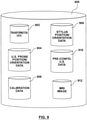
- System 100 has MRI imaging system 106, tracking system 108, ultrasound imaging system 104 and navigation system 102.
- MRI imaging system 106, tracking system 108 and navigation system 102 are communicatively connected via communication network 110 and ultrasound imaging system 104 in a stand-alone system.
- ultrasound imaging system 104 can additionally be communicatively connected via communication network 110.
- communication network 110 can be a local area network, wide area network, wireless network, internet, intranet, or other similar communication network.
- MRI imaging system 106 obtains an MRI image of a tissue of a patient.
- the MRI image obtained is stored locally on MRI imaging system 106 or in some embodiments in a Picture Archiving Communications System (PACS).
- PACS Picture Archiving Communications System
- the image format of the MRI image is a DICOM format, however, skilled persons will understand that other image formats can be used.
- the stored image of the tissue can be reconstructed into a three-dimensional ("3D") image of the tissue and can be displayed by MRI imaging system 106, or another workstation.
- the MRI image when displayed by MRI imaging system 106, can be reformatted and repositioned to view the tissue image at any plane and any slice position.
- MRI imaging system 106 transmits the MRI image to navigation system 102 via communication network 110, where such MRI image can be stored and viewed.
- Skilled persons will understand that the MRI image of a patient can, in alternative embodiments, be stored locally on MRI imaging system 106 and accessed remotely by navigation system 102 via communications network 110, and in other embodiments can be stored on a server in communication with navigation system 102 via communications network 110.
- Navigation system 102 displays the MRI image obtained by MRI imaging system and once reconstructed for display on navigation system 102 the MRI image can be reformatted and repositioned to view the image at any plane and any slice position or orientation. In some embodiments navigation system 102 displays multiple frames or windows on the same screen showing alternative positions or orientations of the MRI-image slice.
- the MRI image obtained by MRI imaging system 106 can be transmitted to navigation system 102 at any point in time and is not necessarily transmitted immediately after obtaining the MRI image, but instead can be transmitted on the request of navigation system 102.
- the MRI image is transmitted to navigation system 102 by a transportable media device, such as a flash drive, CD-ROM, diskette, or other such transportable media device.
- Ultrasound imaging system 104 obtains an ultrasound image of a tissue of a patient, typically using an ultrasound probe, which is used to image a portion of a tissue of a patient within the field of view of the ultrasound probe. Ultrasound imaging system 104 obtains and displays an ultrasound image of a patient's anatomy within the field of view of the ultrasound probe and typically displays the image in real-time as the patient is being imaged. In some embodiments, the ultrasound image can additionally be stored on a storage medium, such as a harddrive, CD-ROM, flash drive or diskette, for reconstruction or playback at a later time.
- a storage medium such as a harddrive, CD-ROM, flash drive or diskette
- navigation system 102 can access the ultrasound image, and in such embodiments ultrasound imaging system 104 is further connected to communication network 1 10 and a copy of the ultrasound image obtained by ultrasound imaging system 104 can be transmitted to navigation system 102 via communication network 1 10.
- navigation system 102 can remotely access and copy the ultrasound image via communication network 100, and in alternative embodiments, a copy of the ultrasound image can be stored on a server in communication with navigation system 102 via communications network 1 10 and accessed remotely by navigation system 102.
- Tracking system 108 is in communication with navigation system 102 via communications network 1 10 and tracks the physical position in which ultrasound imaging system 104 is imaging the tissue of the patient.
- tracking system 108 can be connected directly to navigation system 102 via a direct communication link or wireless communication link.
- Tracking system 108 tracks the position of transmitters connected to ultrasound imaging system 104 and provides navigation system 102 with data representing their co-ordinates in a tracker co-ordinate space.
- tracking system may be an optical tracking system comprising an optical camera and optical transmitters, however skilled persons will understand that any device or system capable of tracking the position of an object in space can be used.
- an RF tracking system can be used, comprising an RF receiver and RF transmitters.
- Ultrasound imaging system 104 is configured for use with navigation system 102 by a calibration process using tracking system 108.
- Transmitters that are removably connected to the ultrasound probe of ultrasound imaging system 104 can transmit their position to tracking system 102 in the tracker co-ordinate space, which in turn provides this information to navigation system 102.
- transmitters may be positioned on the probe of ultrasound imaging system 104 so that tracking system 108 can monitor the position and orientation of the ultrasound probe and provide this information to navigation system 102 in the tracker co-ordinate space.
- Navigation system 102 can use this tracked position to determine the position and orientation of the transducer, an ultrasound probe, relative to the tracked position of the transmitters.
- configuration occurs using a configuration tool, where its position and orientation can be additionally tracked by tracking system 108.
- the configuration tool contacts the transducer face of the ultrasound probe of ultrasound imaging system 104 and tracking system 108 transmits information representing the position and orientation of the configuration tool in the tracker coordinate space to navigation system 102.
- Navigation system 102 can determine a configuration matrix that can be used to determine the position and orientation of the field of view of the ultrasound probe in the tracker co-ordinate space, based on the tracked position of the transmitters connected to the ultrasound probe.
- a database having configuration data of a plurality of brands or models of various ultrasound probes can be used to pre-load a field of view configuration into navigation system 102 during configuration.
- ultrasound imaging system 104 is configured with navigation system 102, the tissue of a patient can be imaged with ultrasound imaging system 104.
- tracking system 108 monitors the position and orientation of the ultrasound probe of ultrasound imaging system 104 and provides this information in the tracker co-ordinate space to navigation system 102. Since ultrasound imaging system 104 has been configured for use with navigation system 102, navigation system 102 is able to determine position and orientation of the field of view of the ultrasound probe of ultrasound imaging system 104.
- Navigation system 102 can be configured to co-register an ultrasound image with an MRI image.
- navigation system 102 can be configured to transform the position and orientation of the field of view of the ultrasound probe from the tracker coordinate space to a position and orientation in the MRI image, for example, to DICOM coordinates. This can be accomplished by tracking the position and orientation of the ultrasound probe and transmitting this positional information in the tracker co-ordinate space to navigation system 102 and relating this positional information to the MRI co-ordinate system.
- a user can select an anatomical plane within the MRI image, and the user can then manipulate the position and orientation of a tracked ultrasound probe to align the field of view of the ultrasound probe with the selected anatomical plane.
- the associated tracker co-ordinate space co-ordinates of the ultrasound image can be captured. Registration of the anatomic axes (superior-inferior (SI), left-right (LR) and anterior-posterior (AP)) between the MRI image and the tracker coordinate space can be determined from the relative rotational differences between the tracked ultrasound field of view orientation and the selected anatomical plane.
- SI superior-inferior
- LR left-right
- AP anterior-posterior
- This configuration further includes the selection of landmark within the MRI image, for example, using an interface permitting a user to select an anatomical target.
- the landmark can be an internal tissue landmark, such as tendon, bone, veins or arteries, and in other embodiments, the landmark can be an external landmark, such as a fiducial skin marker or external landmark, such as a navel or nipple.
- the same landmark selected in the MRI image can be located with the ultrasound probe, and upon location, a mechanism can be provided for capturing coordinates of the representation of the target in the tracker co-ordinate space.
- the relative differences between the coordinates of the target in the MRI image and the co-ordinates of the target in the tracker co-ordinate space are used to determine the translational parameters required to align the two co-ordinate spaces.
- the plane orientation information acquired previously can be combined with the translation parameters to provide a complete 4x4 transformation matrix capable of co-registering the two coordinate spaces.
- Navigation system 102 can then use the transformation matrix to reformat the MRI image being displayed so that the slice of tissue being displayed is in the same plane and in the same orientation as the field of view of the ultrasound probe of ultrasound imaging system 104.
- Matched ultrasound and MRI images may then be displayed side by side, or directly overlaid in a single image viewing frame.
- navigation system 102 can display additional MRI images in separate frames or positions on a display screen.
- the MRI image can be displayed with a graphical representation of the field of view of ultrasound imaging system 104 wherein the graphical representation of the field of view is shown slicing through a 3D representation of the MRI image.
- annotations can be additionally displayed, these annotations representing, for example, the position of instruments imaged by ultrasound imaging system 104, such as biopsy needles, guidance wires, imaging probes or other similar devices.
- the ultrasound image being displayed by ultrasound imaging system 104 can be superimposed on the slice of the MRI image being displayed by navigation system 102 so that a user can view both the MRI and ultrasound images simultaneously, overlaid on the same display.
- navigation system 102 can enhance certain aspects of the super imposed ultrasound or MRI images to increase the quality of the resulting combined image.
- MRI imaging system 106 comprises MRI imager 222 and MRI workstation 224.
- MRI imager 222 is an MRI magnet or other MRI imaging device and is in communication with MRI workstation 224 for obtaining an MRI image of a tissue of interest of patient 216.
- MRI imager 222 and MRI workstation 224 can be any known MRI imaging system, and skilled persons will understand that, in other embodiments, other 3D imaging systems can be used in place of MRI imager 222 and MRI workstation 224, generating alternative 3D images that can be used instead of an MRI image.
- MRI workstation 224 is connected to communication network 110 for transmitting the MRI image obtained during MRI imaging, or any other relevant information and/or data to other workstations or networking devices connected to communication network 110.
- the MRI image obtained is stored locally on MRI workstation 224 and is transmitted to navigation system 102 via communication network 1 10; however, skilled persons will understand that navigation system 102 can access the resulting MRI image remotely via communication network 1 10 from MRI workstation 224 or, in some embodiments, the resulting MRI image can be stored on a network server connected to communication network 110 which can transmit the MRI image to navigation system 102 or can provide remote access to the resulting MRI image. In other embodiments, skilled persons will understand that the MRI image can be stored on a transportable storage medium at MRI workstation 224, such as a CD-ROM, flash drive or diskette, and loaded into navigation system 102. Navigation system 102 can reconstruct and display the MRI image into a 3D image of the tissue that was imaged during the MRI imaging process. The displayed MRI image can be transformed by navigation system 102 to view the MRI image at any plane and any slice position.
- the MRI image obtained can be transmitted to navigation system 102 at any point in time and is not necessarily transmitted immediately after MRI workstation 224 has obtained the completed MRI image. Instead, the MRI image can be transmitted to navigation system 102 on the request of navigation system 102 or by a user using a transportable media device.
- ultrasound imaging system 104 comprises ultrasound probe 204 and ultrasound workstation 202.
- Ultrasound workstation 202 is connected to ultrasound probe 204 for obtaining an ultrasound image of patient 216.
- Ultrasound probe 204 has ultrasound transducer 206 for transmitting sound waves and receiving the reflected sound waves within field of view 210.
- Ultrasound probe 204 is used to obtain an ultrasound image of a tissue of patient 216 who is positioned on examination table 214; however skilled persons will appreciate that patient 216 may be positioned in any convenient location to obtain an ultrasound image of a tissue of interest and on any support structure, for example a chair.
- Ultrasound probe 204 provides data to ultrasound workstation 202 which interprets the data to generate and display an ultrasound image of the tissue of patient 216 within the field of view 210 of ultrasound probe 204.
- ultrasound workstation is a stand-alone workstation; however, in some embodiments, ultrasound workstation 202 can be connected to communication network 110 and can transmit the ultrasound image to navigation system 102 via communication network 110, or in alternative embodiments, through a transportable media device, such as a CD-ROM, flash drive, diskette or other similar transportable media device.
- navigation workstation 102 can access the ultrasound image remotely via communication network 110 or in some embodiments, the ultrasound image can be stored on a network server in communication with communication network 110 and navigation system can remotely access, or obtain a copy, from such network server via communication network 110.
- tracking system 108 comprises optical camera 218 and a plurality optical transmitters; however, skilled persons will understand that alternative tracking systems can be used, such as RF magnetic tracking systems.
- Optical camera 218 is connected to communication network 110 for transmitting the three dimensional coordinate data of the plurality of optical transmitters to navigation system 102 in the tracker co-ordinate space.
- Optical camera 218 monitors the position and orientation of ultrasound probe 204 by tracking ultrasound transmitters 250 and transmits this data to navigation system 102 via communication network 110.
- Skilled persons will appreciate that in some alternative embodiments, optical camera 218 can be connected directly to navigation system 102 via a direct communication link, which may be a physical communication link or a wireless communication link.
- ultrasound probe 204 is removably engaged to ultrasound tracker 208 which has ultrasound transmitters 250 that are tracked by optical camera 218 in the tracker co-ordinate space.
- ultrasound transmitters 250 are optical transmitters tracked by optical camera 218, other transmitter-receiver systems can be used.
- RF transmitters and receivers can be used to track the position and orientation of ultrasound probe 204 in the tracker co-ordinate space.
- orientations and positions of ultrasound transmitters 250 on ultrasound tracker 208 can be used to provide position and orientation information detectable by optical camera 218 and transmitted to navigation system 102.
- transmitters that are removably connected to ultrasound probe 204 can tend to provide the ability to configure any ultrasound probe with any shape of transducer, such as linear transducers, curvilinear transducers and array and phased array transducers.
- ultrasound tracker 208 having extension arm 306 and branches 310 with ultrasound transmitters 250 connected to branches 310 of ultrasound tracker 208.
- Ultrasound tracker 208 additionally has engagement brace 302 and locking screw 304, engagement brace 302 connectable to ultrasound bracket 314 by slidable connection to engagement bracket 316.
- Locking screw 304 is turned to lock engagement brace 302 to engagement bracket 316.
- Ultrasound bracket 314 additionally has connection arms 312 for frictional engagement to ultrasound probe 204 when in use. Skilled persons will appreciate that other mechanical means can be used to maintain the position of ultrasound tracker 208 on ultrasound probe 204.
- ultrasound probe 204 is configured to be used with navigation system 102 using stylus 212.
- Stylus 212 is fitted with stylus transmitters 252 and its position and orientation is received by optical camera 218 in the tracker coordinate space.
- the orientation and position information of stylus 212 is transmitted to navigation system 102 via communication network 110 where it is used to configure ultrasound imaging probe 204 with navigation system 102 so that navigation system 102 can determine the position and orientation of field of view 210 of ultrasound probe 204 in the tracker co-ordinate space.
- stylus 212 is shown, having tip 502 and stylus transmitters 252 arranged at locations on stylus 212 to provide position and orientation data of stylus 212 to camera 218.
- stylus 212 is an exemplary embodiment of a configuration tool that can be used to configure ultrasound probe 204 with navigation system 102 so that navigation system 102 can determine field of view 210 of ultrasound probe 204.
- Other configuration tools may be used.
- navigation system 102 is set to a configuration mode, where an operator can use stylus 212 to configure ultrasound probe 204 with navigation system 102.
- tip 502 of stylus 212 can be touched to predetermined points on transducer 206 to configure ultrasound probe 204 with navigation system 102.
- Navigation system 102 can use a pre-computed 4 4 stylus calibration matrix to determine the co-ordinates of stylus tip 502 in the tracker co-ordinate space given the tracked position and orientation of the stylus transmitters 252.
- a user acknowledges with navigation system 102 that stylus 212 is in contact with a first corner of the face of transducer 206 on navigation system 102, and the position of the first corner of the face of transducer 206 is recorded by navigation system 102 in tracker co-ordinate space.
- the user moves stylus 212 to each corner of the face of transducer 206 and acknowledges such corner on navigation system 102, and at the conclusion of acknowledging and recording the position of each corner of transducer 206 in the tracker co-ordinate space, navigation system 102 can configure ultrasound probe 204 by determining the geometric relationship between field of view 210 and ultrasound tracker 208.
- Navigation system 102 can additionally perform an error check on the configuration and can reject the configuration of ultrasound probe 204 if, for example, the user improperly positioned stylus 212 during the configuration procedure, or if, for example, the user improperly acknowledged the position of stylus 212 during the configuration procedure.
- field of view 210 of ultrasound probe 204 can be configured in navigation system 102 by accessing a database of pre-configuration data based on the brand and type of ultrasound probe being configured. In such embodiments, it may be desirable to position ultrasound tracker 208 in a predetermined position on ultrasound probe 204 based on the specific brand and type of ultrasound probe 204 being configured.
- This pre-configuration data can also be used when field of view 210 of ultrasound probe 204 is configured using stylus 212, or another configuration tool, to error check the calculated geometric relationship between field of view 210 and ultrasound tracker 208. For example, the determined geometric transformation can be compared to the pre-configuration data to determine if it is within a tolerance value, and if not, navigation system 102 may prompt the user to re-configure ultrasound probe 204.
- Navigation system 102 can be configured to transform the position and orientation of the field of view of the ultrasound probe from the tracker co-ordinate space to a position and orientation in the MRI image, for example, to DICOM co-ordinates. This can be accomplished by tracking the position and orientation of field of view 210 of ultrasound probe 204 based on the tracked position of ultrasound transmitters 250, transmitting this positional information in the tracker co-ordinate space to navigation system 102 and relating this positional information to the MRI co-ordinate system. For example, in some embodiments, this configuration can occur by a user selecting an anatomical plane within the MRI image and a user can then align ultrasound probe 204 so that field of view 210 is in the selected anatomical plane.
- the associated tracker co-ordinate space co-ordinates of the ultrasound image can be captured. Registration of the anatomic axes (superior-inferior (SI), left-right (LR) and anterior-posterior (AP)) between the MRI image and the tracker co-ordinate space can be determined from the relative rotational differences between the tracked ultrasound field of view orientation and the selected anatomical plane.
- SI superior-inferior
- LR left-right
- AP anterior-posterior
- a landmark in the MRI image can be selected using, for example, a user interface that permits the user to select the landmark.
- the landmark can be an internal tissue landmark, such as tendon, bone, veins or arteries, and in other embodiments,
- the target can be an external landmark, such as a fiducial skin marker or external landmark, such as a navel or nipple.
- the same landmark selected in the MRI image can be located with ultrasound probe 204, and upon location, a mechanism can be provided for capturing coordinates of the representation of the target in the tracker co- ordinate space.
- the relative differences between the coordinates of the target and the coordinates of the MRI image and the located target in the tracker co-ordinate space are used to determine the translational parameters between the two co-ordinate spaces.
- the plane orientation information can be combined with the previously acquired translation parameters to provide a complete 4x4 transformation matrix which can co-register the tracker space and MRI space co-ordinate systems.
- navigation system 102 can display additional MRI images in separate frames or positions on a display screen.
- the MRI image can be displayed with a graphical representation of field of view 210 of ultrasound probe 204 wherein the graphical representation is positioned to represent the position and orientation of field of view 210.
- a graphical representation of field of view 210 may be displayed in a plane normal to field of view 210 and navigation system 102 can show a 3D MRI image of the tissue of the patient, but rotated and oriented to show the position and orientation of the tissue of patient 216 relative to field of view 210 of ultrasound probe 204.
- the ultrasound image being displayed by ultrasound imaging system 104 can be superimposed on the slice of the MRI image being displayed by navigation system 102 such that a user can view both the MRI and ultrasound images simultaneously, overlaid on the same display.
- navigation system 102 can enhance certain aspects of the ultrasound or MRI images to increase the quality of the resulting combined image.
- Ultrasound workstation 202 has display 602, ultrasound 170 604, ultrasound image processing module 606 and ultrasound image data 608.
- Ultrasound I/O 604 communicates with ultrasound probe 204, such that transducer 206 produces sound waves that penetrate the tissue of patient 216 and reflect off internal tissue elements in patient 216 the reflected sound waves being received by transducer 206 and transmitted to and received by ultrasound I/O 604.
- the ultrasound data received is processed by ultrasound image processing module 606 to generate an ultrasound image of the tissue of patient 216 in field of view and displayed on display 602.
- Display 602 shows an ultrasound image of the tissue of patient 216 in field of view 210 of ultrasound probe 204.
- ultrasound workstation 202 can communicate via communication network 110 to transmit data, such as ultrasound image data 608, to other nodes or network elements, such as navigation system 102, in communication with communication network 110.
- data such as ultrasound image data 608
- ultrasound workstation 202 may consist of other configurations and may include additional elements that enable ultrasound workstation 202 to obtain and display an ultrasound image of the tissue of patient 216 in field of view 210 of ultrasound probe 204.
- MRI workstation 224 having display 702, MRI I/O 704, MRI image processing module 706 and MRI image data 708.
- MRI I/O 704 communicates with MRI imager 222 for sending and receiving excitation signals during the MRI imaging process.
- MRI image processing module 706 receives signals from MRI I/O 704 and detects and processes these signals to generate MRI image data 708.
- MRI image data 708 is additionally processed by MRI image processing module 706 to display an MRI image of the tissue of patient 216 on display 702 which can be reformatted and repositioned using user interface devices, for example a mouse, keyboard, touch screen, or other similar user interface device, to display MRI image 708 at any plane and any slice position.
- user interface devices for example a mouse, keyboard, touch screen, or other similar user interface device, to display MRI image 708 at any plane and any slice position.
- Skilled persons will appreciate that MRI workstation 224 may consist of other configurations and may include additional elements that enable MRI workstation 224
- Navigation system 102 has calibration module 802, tracking module 804, image processing module 806, transformation configuration module 812, navigation system data 808, and display 810.
- navigation system data 808 is provided and comprises transformation data 902, ultrasound probe position and orientation data 904, stylus position and orientation data 906, calibration data 908, pre-configuration ultrasound data 910, MRI image data 912.
- Ultrasound position module 1104 receives information from optical camera 218 through communications network 110 and interprets that information to generate ultrasound position and orientation data 904 in the tracker co-ordinate space.
- Stylus position module 1106 receives information from optical camera 218 through communications network 110 and interprets that information to generate stylus position and orientation data 906 in the tracker co-ordinate space.
- Stylus position module 1106 can additionally determine the physical position and orientation of tip 502 of stylus 212 based on a pre-configured 4 4 stylus transformation matrix based on the position of stylus transmitters 252 on stylus 212.
- Calibration module 802 calibrates field of view 210 of ultrasound probe 204 with navigation system 102 using ultrasound probe position and orientation data 904 and stylus position and orientation data 906 to generate and store calibration data 908.
- calibration module 802 is shown and consists of calibration configuration module 1002, error correction module 1004 and pre-configuration module 1006.
- Calibration configuration module 1002 determines the calibration matrix used to transform ultrasound position and orientation data 904 in the tracker co-ordinate space into coordinates representing the position and orientation of field of view 210 in MRI image 912.
- stylus 212 is used to select the four corner points of the face of transducer 206 and navigation system 102 can store the tracked stylus position and orientation data 906 relative to the coordinate frame of ultrasound transmitters 250.
- the computed column vectors can be defined in the co-ordinate frame of ultrasound transmitters 250.
- navigation system 102 provides a visual prompt to a user and indicates which corner of the face of transducer 206 should be selected by stylus 212; however in alternative embodiments the user can select any corner point and may not be prompted for a specific corner point.
- a user touches tip 502 of stylus to the specified corner point of the face of transducer 206 and provides a user acknowledgement to navigation system 102, typically through a user interface device, such as, a keyboard, mouse, or touch screen.
- navigation system 102 can store the tracked position of stylus tip 502 in stylus position and orientation data 908 relative to the co-ordinate frame of ultrasound transmitters 250.
- calibration configuration module 1002 performs a principle components analysis using the four corner points as inputs.
- the origin (O) of the coordinate frame of transducer 206 is located at the mean of the corner points stored in stylus position and orientation data 906.
- the mean is calculated as the vector sum of the four corner points divided by a scalar factor of 4.
- calibration configuration module 1002 continues the principle components analysis and determines the Z, Y, and X axes of the co-ordinate frame defined by transducer 206 which can be defined as the 1st, 2nd and 3rd principle components of the principle components analysis.
- a convention can be defined to reproducibly assign the positive "sense" of each of the X, Y and Z axes.
- the 4 ⁇ 4 configuration matrix can be determined as [X Y Z O; 0 0 0 1 ] where X, Y, Z and O are three element column vectors, which can be used to transform tracked position and orientation information in the co-ordinate frame of transducer 206 into the tracker coordinate space.
- stylus 212 is used to select the four corner points of the face of transducer 206.
- navigation system 102 can store the tracked position of stylus tip 502 in stylus position and orientation data 908 relative to the co-ordinate frame of ultrasound transmitters 250.
- the co-ordinates of the four corner points can be defined as the upper-left, upper-right, lower-left and lower-right, which can be three dimensional column vectors specified in the co-ordinate frame of ultrasound transmitters 250.
- display 810 of navigation system 102 provides a visual prompt to a user and indicates which corner of the face of transducer 206 should be selected by stylus 212; however in alternative embodiments the user can select any corner point and may not be prompted for a specific corner point.
- a user touches tip 502 of stylus 212 to the specified corner point of the face of transducer 206 and provides a user acknowledgement to navigation system 102, typically through a user interface device such as a keyboard, mouse, or touch screen.
- tracking module 804 records the position and orientation of tip 502 of stylus 212 determined from the position and orientation of stylus transmitters 252 on stylus 212.
- Each corner point is stored in stylus position and orientation data 906.
- the user may select each corner point of the face of transducer multiple times and tracking module 804 averages the multiple selections of the same corner point, which can tend to reduce errors due to noise and user selection variability.
- calibration configuration module 1002 determines the origin (O) of the coordinate frame of transducer 206 which is located at the vector sum of the corner points stored in stylus position and orientation data 906, divided by a scalar factor of 4, specified in co-ordinates in the co-ordinate frame of ultrasound transmitters 250. At 1406, calibration configuration module 1002 uses the four corner points to determine a plane representing the face of ultrasound probe 202.
- calibration configuration module 1002 determines the normal of the plane representing the face of ultrasound probe 206, which corresponds to the X vector for the coordinate frame of transducer 206, meaning the vector along the axis of ultrasound probe 206. Additionally, at 1406, calibration configuration module 1002 performs a check to see if the sense of vector X points toward the image plane rather than towards the handle of ultrasound probe 204, which can be done by calculating the dot product of the X vector and any point on the face of transducer 206 (including O or any of the 4 corner points) wherein if the dot product is positive, the X vector is pointing towards the image plane, and if not, the X vector may be negated so that it is pointing towards the image plane.
- calibration configuration module 1002 determines the vector defined by the upper left and upper right corner points and additionally determines the vector defined by the lower left and lower right corner points.
- Calibration configuration module 1002 defines both vectors to be the Z vector, or in some embodiments, may average the two vectors to obtain an estimate of the Z vector.
- calibration configuration module 1002 determines the Y vector of the coordinate frame of transducer 206 which is the cross product of the X and Z vectors. Skilled persons will understand if the Y vector is directed in a negative direction the Y vector can be negated to form a right handed coordinate system.
- calibration configuration module 1002 stores the 4 ⁇ 4 calibration matrix as calibration data 908, wherein the 4 ⁇ 4 calibration matrix can be defined as [X Y Z O, 0 0 0 1], which can be used to transform tracked position and orientation information in the co-ordinate frame of transducer 206 into the tracker coordinate space.
- stylus 212 is used to select the four corner points of the face of transducer 206.
- navigation system 102 can store the tracked position of stylus tip 502 in stylus position and orientation data 908 relative to the co-ordinate frame of ultrasound transmitters 250.
- display 810 of navigation system 102 provides a visual prompt to a user and indicates which corner of the face of transducer 206 should be selected by stylus 212; however in alternative embodiments the user can select any corner point and may not be prompted for a specific corner point.
- a user touches tip 502 of stylus 212 to the specified corner point of transducer 206 and provides a user acknowledgement to navigation system 102, typically through a user interface device such as a keyboard, mouse, or touch screen.
- tracking module 804 records the position and orientation of tip 502 of stylus 212 determined from the position and orientation of stylus transmitters 252 on stylus 212.
- Each corner point is stored in stylus position and orientation data 906.
- the user may select each corner point of the face of transducer multiple times and tracking module 804 averages the multiple selections of the same corner point, which can tend to reduce errors due to noise and user selection variability.
- calibration configuration module 1002 determines the origin (O) of the coordinate frame of transducer 206 which is located at the vector sum of the corner points stored in stylus position and orientation data 906 divided by a scalar factor of 4.
- the mean vector sum is calculated by the average vector sum of the four corner points.
- calibration configuration module 1002 uses a principle components analysis function, using the compiled list of all of the selected corner points (xi, yi and zi) as input.
- the principle components analysis function is insensitive to the order of the input points, so one may not have to know which corner points are which.
- the calibration configuration module 1002 using the principle components analysis function, outputs three principle components, each representing a three dimensional vector.
- the first principle component is the direction which explains the most variability in the data and is defined as the Z vector specified in the co-ordinate frame of ultrasound transmitters 250.
- the second principle component is the direction which is orthogonal to the first principle component and explains the most of the remaining variability in the data is defined as the Y vector specified in the co-ordinate frame of ultrasound transmitters 250.
- the remaining third principle component is the direction which explains the least variability in the data and is defined as the X vector specified in the co-ordinate frame of ultrasound transmitters 250.
- Calibration configuration module 1002 determines the correct sense of the Z, Y and X vectors of transducer 206 by determining the dot products of each of vectors X and Y vector with the origin of the co-ordinate frame of transducer 206.
- the sign of the dot product can be used to insure that the directions of the X, Y, and Z vectors are consistent with a previously defined sign convention. For example, if the previously defined sign convention is that the X vector is positive pointing along the transducer axis toward the ultrasound image plane and away from the transducer handle, then the dot product of X and O should be positive. If this dot product is negative, the X vector can be negated to be consistent with the previously defined sign convention.
- the dot product of Z and O should be negative, assuming that the transmitters 250 are also located on the top surface of the transducer. If this dot product is positive, the Z vector can be negated to be consistent with the previously defined sign convention.
- the direction of the Y vector can then be chosen to provide a right handed co-ordinate system, i.e., Y points in the direction of the negated cross product of X and Z.
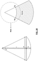
- calibration configuration module 1002 stores the 4 ⁇ 4 calibration matrix as calibration data 908, wherein the 4 ⁇ 4 calibration matrix can be defined as [X Y Z O, 0 0 0 1], which can be used to transform tracked position and orientation information in the coordinate frame of transducer 206 into the tracker co-ordinate space.
- ultrasound probe 202 has a curvilinear transducer
- additional steps can be performed to compensate for the curvilinear transducer.
- navigation system 102 can store the tracked position of stylus tip 502 in stylus position and orientation data 908 relative to the coordinate frame of ultrasound transmitters 250.
- stylus 212 a user can select the approximate center for transducer 206, which can define a 3 dimensional column vector (C) which can be the co-ordinate of the approximate center of the face of transducer 206 in the co-ordinate frame of ultrasound transmitters 206.
- Vector C as well as the previously computed O vector, can be projected onto the X axis of the co-ordinate frame of transducer 206.
- the scalar distance (D) between the projections of the C and O vectors can be computed by taking the absolute value of the difference between the projections of the vectors C and O onto the X vector of the co-ordinate frame of transducer 206.
- This distance D can be the distance that the co-ordinate frame of transducer 206 can be shifted from the previously computed origin O, along the X axis of the co-ordinate frame of transducer 206.
- the vector O can be shifted by the distance D along the X axis of the co-ordinate frame of transducer 206 to bring the co-ordinate frame of transducer 206 to the location of the surface of transducer 206.
- the origin O of the co-ordinate frame of transducer 206 will lie behind the face of transducer 206, in the plane of the 4 corners of the face of transducer 206.
- error correction module 1004 can perform various tests to determine the accuracy of the transducer calibration with respect to predefined tolerance levels.
- error correction module 1004 determines the best fit plane of each of the corner points and if the perpendicular distance from any corner point to the best fit plane is greater than a predetermined error distance, for example, 2.0 mm, the calibration matrix generated by configuration calibration module 1002 is rejected and the user is prompted to re-configure ultrasound probe 204 with navigation system 102.
- a predetermined error distance for example, 2.0 mm
- error correction module 1004 computes the center of the face of transducer 206 using the corner points and the distance from each corner point to the computed center is determined. Those distances are compared and if there is a variation between the shortest distance and the longest distance of more than a predetermined value, for example, 2.0 mm, the calibration matrix generated by configuration calibration module 1002 is rejected and the user is prompted to re-configure ultrasound probe 204 with navigation system 102.
- a predetermined value for example, 2.0 mm
- error correction module 1004 projects each of the corner points onto a line that intersects the computed center point of the face of transducer 206 and is perpendicular to field of view 210. The distance between each projection and the computed center point is determined and if there is a variation between the shortest distance and the longest distance of more than a predetermined value, for example, 2.0 mm, the calibration matrix generated by configuration calibration module 1002 is rejected and the user is prompted to re-configure ultrasound probe 204 with navigation system 102.
- a predetermined value for example, 2.0 mm
- error correction module 1004 proj ects each of the corner points onto a line that is normal to transducer 206 and containing the computed center point of the face of transducer 206.
- the distance between each projection and the computed center point is determined and if there is a variation between the shortest distance and the longest distance of more than a predetermined value, for example, 2.0 mm, the calibration matrix generated by configuration calibration module 1002 is rejected and the user is prompted to re-configure ultrasound probe 204 with navigation system 102.
- error correction module 1004 determines the angle between the vector that is normal to the face of transducer 206 and the vector extending from tip 502 of stylus 212 as stylus 212 contacts each corner point of the face of transducer 206 during configuration. If any of the calculated angles are greater than a predetermined amount, for example 20 degrees, the calibration matrix generated by configuration calibration module 1002 is rejected and the user is prompted to re-configure ultrasound probe 204 with navigation system 102.
- a predetermined amount for example 20 degrees
- error correction module 1004 can be implemented by error correction module 1004 after or during calibration by calibration configuration module 1002. Additionally, skilled persons will understand that alternative error correction steps can be implemented to determine if the calibration matrix generated by calibration configuration module 1002 should be rejected and a re-calibration of ultrasound probe 204 with navigation system 102 should occur.
- calibration module 802 additionally has pre-configuration module 1006, which skilled persons will understand is an optional element in calibration module 802.
- Pre-configuration module can receive an input from a user, using a user input device such as a keyboard, mouse, touch screen, or other similar user input device, representing a brand or model number of a known ultrasound probe. The calculated dimensions of the ultrasound transducer face can then be compared against the known dimensions of this transducer as determined by previous calibrations or manufacturer mechanical specifications. The transducer calibration can then be rejected by the system if this discrepancy exceeds a pre-specified error threshold.
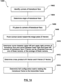
- process 1600 is shown, process 1600 being carried out by transformation configuration module 812 to determine a transformation matrix capable of being used to co-register the tracker co-ordinate space with the co- ordinate space of the MRI image.
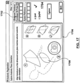
- the type of ultrasound probe 204 is identified by transformation configuration module 812. This identification can be provided by user input using navigation system, for example using drop down menu 1702 on display 810, as shown in Figure 17 . Using drop down menu 1702 a user can select a type of ultrasound probe, such as a curvilinear ultrasound probe or a flat ultrasound probe.
- a user selects the anatomic plane orientation to position ultrasound probe 204 relative to the tissue of the patient.
- a user can select a particular plane of orientation such as axial or sagittal, and a viewing window 1706 and planar image 1708 can be displayed representing field of view 210. Skilled persons will understand that the choice of a particular plane can depend on a variety of factors, such as the particular tissue being imaged. It should be noted that the present invention is not limited in any matter to the selection of any particular plane.
- the user positioned ultrasound probe 204 in the selected plane of orientation.
- This alignment can be determined visually by the user or can additionally be determined mathematically by correspondence of desired number of planar points by the navigation system.
- the ultrasound position and orientation as well as the ultrasound image is captured.
- a user can select capture selection 1704; however, skilled persons will understand that any user acknowledgement can initiate a capture, such as a foot pedal, keyboard stroke, mouse selection, or any other similar user acknowledgment device.
- the directions of the anatomic axes (superior-inferior (SI), left-right (LR) and anterior-posterior (AP)) within the tracker co-ordinate space can be inferred by the orientation of ultrasound probe 204.
- the rotational parameters of the transformation matrix are determined from the rotational offsets between the directions of the anatomical axes in the tracker co-ordinate space and their implicit directions in the MRI image. Once the three rotational parameters of the registration have been calculated, the transformation matrix is completed by calculating three translational parameters to define a six degree of freedom rigid body matrix.
- a landmark is identified in the MRI image displayed on display 810 of navigation system 102.
- landmark 1804 can be identified on display 1802 by a user. Skilled persons will understand that while in the embodiment shown the landmark identified is an internal tissue landmark, in other embodiments external anatomical landmarks can be identified.
- Transformation configuration module 812 stores the co-ordinates of landmark 1804 in the MRI image in transformation data 808.
- the landmark can be an internal tissue landmark, such as tendon, bone, veins or arteries, and in other embodiments, the landmark can be an external target, such as a fiducial skin marker or external landmark, such as a navel or nipple.
- the user positions ultrasound probe 204 so that field of view 210 can detect the internal landmark in the tissue of the patient and the ultrasound image is displayed by ultrasound workstation 202 on display 602. Once the internal landmark is displayed on display 602, the user can freeze the ultrasound image displayed on display 602.
- the user uses standard measurement tools to measure the distance between the landmark in field of view 210 and the upper right and left corners of field of view 210 of ultrasound probe 204.
- This distance information can be used to determine the co-ordinates of the landmark in the co-ordinate frame of transducer 206, meaning the distance of the landmark from the center point of the face of transducer 206 along the axial and lateral axes of ultrasound probe 204 and the calibration matrix, described above, can be used to transform these co-ordinates into the tracker co-ordinate space.
- ⁇ L cos ⁇ 1 F 2 + d L 2 ⁇ d R 2 2 Fd L
- the co-ordinates of the selected target relative to the front center of the ultrasound transducer face would be ( ⁇ - ⁇ , y) where x and y are computed using equations [1] and [2], and ⁇ is computed using equation [3].
- Transformation configuration module 812 can compute the transformation matrix, which can convert co-ordinates in the co-ordinate frame of tracking system 108 to coordinates in the MRI image.
- the methods described herein describe the generation of a matrix for transforming co-ordinates in the MRI image to the tracker space co-ordinate frame; however, skilled persons will understand that the geometric transformation from tracker space to MRI space is a linear, invertible operation, and the transformation matrix from tracker space to MRI space is the matrix inverse of the matrix transformation from MRI space to tracker space.
- the vectors corresponding to the AP, SI and LR directions in the coordinate frame of tracking system 108 are determined by the orientation of ultrasound probe 204 when the axial plane is acquired, combined with the previously computed transducer configuration matrix. Skilled persons will understand that in the embodiment shown, the axial plane is the selected plane, however other planes can be selected, such as a sagittal or coronal plane.
- the SI direction will correspond to the slice axis of ultrasound probe 204
- the LR direction will correspond to the lateral axis of ultrasound probe 204
- the AP 01871 direction will correspond to the axial axis of ultrasound probe 204.
- Unit vectors along each of these directions can be computed in the tracker co-ordinate space using the tracked position and orientation of transducer 206. This can yield three unit vectors in the tracker co-ordinate space that represent the AP, LR and SI directions of the 3d MRI image (which will be referred to as the AP tracker , LR tracker and SR tracker vectors. Note that this correspondence assumes that the MRI image was acquired with the patient in a known orientation with respect to the coordinate axes used to define the MRI data acquisition.
- the representations of these unit column vectors in the tracker co-ordinate space are placed in the first three columns of a 4 ⁇ 4 transformation matrix (with the fourth row of the 4 ⁇ 4 transformation matrix containing [0 0 0 1].
- the order of the AP tracker , LR tracker and SI tracker vectors should match the order of the corresponding axes of the MRI image.
- the sign of these vectors may have to be negated to match the MRI co-ordinate system, for example, if the AP axis is positive in the anterior direction in the MRI image, the AP tracker vector would be negated before being inserted into the transformation matrix to match the MRI co-ordinate system, since ultrasound probe was pointing posteriorly when the plane orientation was captured.
- the co-ordinates of the landmark in the tracker space should be converted into co-ordinates along the AP, LR and SI axes. This can be accomplished by projecting the co-ordinates (xo, yo, zo) onto each of the AP, LR and SI axes in tracker coordinate space (which are determined by the transducer orientation when the anatomic plane was selected).
- the resulting projected co-ordinates of the landmark (referred to as APproj, LRproj and SIproj) are now in a co-ordinate system with the same axes as the MRI image (for example DICOM co-ordinates), however, having a different origin (the origin is the origin of the tracker coordinate space, not the origin of the MRI/DICOM space).
- the translation components of the transformation matrix can be computed by taking the difference between the MRI coordinates of the selected landmark and the projected coordinates of the ultrasound selected landmark, where the offsets can be calculated as AP proj - AP dicom , LR proj - LR dicom and SI proj - Si dicom -
- These offsets represent rows 1 to 3 of column 4 in 4 ⁇ 4 transformation matrix, the order reflecting the order of the DICOM dimensions in the MRI image, for example, if the DICOM dimensions are AP, LR and SI, row 1 contains the AP offset, row 2 contains the LR offset, etc.
- the resulting 4 ⁇ 4 transformation matrix defines the transformation from the co-ordinate space of the MRI image to the tracker co-ordinate space, thus, the transformation matrix from the tracker co-ordinate space to the co-ordinate space of the MRI image is the inverse of the determined 4 ⁇ 4 transformation matrix.
- FIG. 12 an embodiment of method 1200 is shown representing the use of system 100.
- patient 216 is positioned in an MRI system to obtain an MRI image of a tissue of patient 216.
- An MRI image of a tissue of patient 216 is obtained using MRI system 106 and is transmitted, via communication network 110 to navigation system 102.
- the transmission of the obtained MRI image is not required to occur immediately after the MRI image is obtained, but can be transmitted upon request of navigation system 102 or can be transported by a user on a transportable media device, for example a flash drive, CD-ROM or diskette.
- navigation system 102 can access the MRI image remotely via communication network 110.
- patient 216 is transported to an ultrasound imaging area for ultrasound imaging by ultrasound imaging system 104.
- the ultrasound imaging area is in the same location as MRI imaging system 106 and patient 216 does not need to be physically moved to the ultrasound imaging area, but instead, ultrasound imaging system 104 is brought to patient 216, who remains in the same position they were in during MRI imaging.
- ultrasound imaging system 104 is calibrated with navigation system 102.
- display 810 prompts a user to position stylus 212 on corners of transducer 206 and upon positioning of stylus 212 on each of the corners of transducer 206, the user provides a user acknowledgement to navigation system 102, typically using a user interface device such as a keyboard, mouse, touch screen or foot pedal, to acknowledge that the stylus 212 is at the desired position.
- a user interface device such as a keyboard, mouse, touch screen or foot pedal
- ultrasound probe 204 and stylus can be monitored by tracking system 108, in some embodiments ultrasound probe 204 being fitted with ultrasound transmitters 250 and stylus being fitted with stylus transmitters 252, each being monitored by optical camera 218 which transmits data to navigation system 102 representing the physical position and orientation of each of ultrasound probe 204 and stylus 212.
- navigation system 102 After the user has acknowledged each of the user prompts provided during the configuration process at 1206, at 1208 navigation system 102 error checks the calibration performed at 1206. If an error in calibration is detected, the user must recalibrate ultrasound imaging system 104 with navigation system 102.
- the transformation matrix is determined by navigation system 102, which can be used to transform co-ordinates in the coordinate frame of transducer 206 into co-ordinates in the MRI image.
- the user performs an ultrasound scan of the tissue of patient 216 using ultrasound imaging system 104.
- the user administers ultrasound gel to the surface of the tissue being imaged with ultrasound probe 204 and the user positioned ultrasound probe 204 to desired positions to obtain images.
- ultrasound system 104 displays the obtained ultrasound image on display 602.
- navigation system 102 displays and reformats the MRI image displayed on display 810 so that the slice of the MRI image shown is in the same plane and orientation that ultrasound imaging system 104 is imaging the tissue of patient 216 and is concurrently displayed by ultrasound imaging system 104.
- the series of reformatted images of MRI image displayed on display 810 can be stored on navigation system 104, or in some embodiments on a data storage medium, for subsequent play back by a user on navigation system 104 at a later point in time.
- a method for transforming a displayed three-dimensional image corresponding to a position and orientation of a field of view of an imaging probe comprising:
- Clause 6 The method of clause 5, wherein the transducer is curvilinear in shape and the method further comprises shifting the position of the origin (O) to compensate for the curvilinear shape of a the face of the transducer.
- Clause 7 The method of clause 1 , further comprising checking for errors in calibrating the field of view.
- Clause 8 The method of clause 1, wherein the co-registering of the first and second coordinate spaces comprises determining a 4 ⁇ 4 transformation matrix having a rotational component and a translational component.
- Clause 11 The method of clause 10, wherein the field of view is curvilinear in shape and the method further comprises offsetting the axial distance to compensate for the curvilinear shape of the field of view.
- Clause 14 The method of clause 1, wherein the three dimensional image is an MRI image and the imaging probe is an ultrasound imaging probe.
- a method for calibrating a field of view of an imaging probe relative to a plurality of transmitters removably connected to the imaging probe comprising:
- Clause 18 The method of clause 17, where the transducer is curvilinear in shape and the method further comprises shifting the position of the origin (O) to compensate for the curvilinear shape of the face of the transducer.
- a method of co-registering a first co-ordinate space with a second co-ordinate space comprising:
- An apparatus for transforming a displayed three-dimensional image corresponding to a position and orientation of a field of view of an imaging probe comprising:
- Clause 21 The apparatus of clause 20, further comprising an error correction capable of checking for errors in calibrating the field of view.
- a computer-readable medium having instructions thereon for causing a processor to execute the instructions, the instructions adapted to be executed to implement a method for transforming a displayed three-dimensional image corresponding to a position and orientation of a field of view of an imaging probe, the method comprising:
- a method of determining the co-ordinates of a landmark visible in a field of view ultrasound image in a co-ordinate space comprising:
- Clause 24 The method of clause 23, wherein the transducer is curvilinear in shape and the method further comprises offsetting the axial distance to compensate for the curvilinear shape of the transducer.
Abstract
Description
- This application claims priority from
United States Provisional Application No. 61/264,743 filed November 27, 2009 United States Provisional Application No. 61/394,734 filed October 19, 2010 - This invention relates to the field of medical imaging and more specifically relates to dynamically transforming a displayed three dimensional medical image of a tissue.
- Medical imaging devices provide non- invasive methods to visualize the internal structure of a patient. Such non-invasive visualization methods can be helpful in treating patients for various ailments. For example, the early detection of cancer in a patient can be important in treating that patient. For most cancers, when detected at an early stage, the survival probability of the patient can increase.
- There are many medical imaging methods available for visualizing the internal structure of a patient, each with its own benefits and its own limitations and while the examples and embodiments described herein relate to MRI systems, MRI scanners and MRI images, any displayed three-dimensional image can be dynamically transformed using the systems and methods described herein, for example a three-dimensional CT image, three-dimensional optical coherence tomography image, or other three-dimensional medical image of a tissue of a patient such as single photon emission computed tomography or positron emission tomography. Additionally, it will be appreciated there are many medical imaging methods that use a probe having a field of view and while the examples and embodiments described herein relate to ultrasound systems having a field of view, any medical imaging method having a field of view can be used in the systems and methods described herein, including OCT (optical) sensors and PET detectors.
- Magnetic resonance imaging (MRI) is one such non-invasive medical imaging technique which uses magnetic fields to image tissue of a patient. A patient is placed inside a powerful uniform magnetic field of an MRI scanner, which can align the magnetic moments of protons in the tissue (typically hydrogen protons of water molecules in the tissue) in the direction of the field, precessing about the field at their Larmor frequency. An excitation magnetic field (typically orthogonal to the main magnetic field) near the Larmor frequency is applied to alter the alignment of the protons in the tissue, typically flipping the magnetic moment of the protons in the main field. When the excitation field is turned off, the protons emit a photon that can be detected and processed to form an MRI image of the tissue.
- Ultrasound imaging, another non-invasive medical imaging technique, uses sound waves, typically produced by piezoelectric transducers to image a tissue in a patient. The ultrasound probe focuses the sound waves, typically producing an arc-shaped sound wave which travels into the body and is partially reflected from the layers between different tissues in the patient. The reflected sound wave is detected by the transducer and converted into electrical signals that can be processed by the ultrasound scanner to form an ultrasound image of the tissue.
- Each of MRI imaging and ultrasound imaging has certain advantages and certain drawbacks. For example, ultrasound tends to provide improved imaging of tendon structure in a patient over the images of the same tendon structure provided by an MRI. Ultrasound tends to provide superior spatial resolution over similar images obtained by an MRI machine.
- MRI imaging tends to provide superior soft-tissue contrast resolution as compared to ultrasound images, typical MRI images tending to allow individual structures such as a lung, liver, kidney, bowel, and gray and white matter to be distinguished. Additionally, ultrasound provides a smaller field-of-view as compared to MRI imaging, and the resolution of ultrasound images tends to be restricted by the sound wave penetration through soft tissues and bone. For example, ultrasound imaging has difficulty penetrating bone and thus typically only sees the outer surface of bone structure and not what lies within.
- An advantage of ultrasound as compared to MRI imaging is that ultrasound imaging provides real-time feedback. For example, an ultrasound technician can position the ultrasound transducer directly on a patent in a first position and view the ultrasound image in real time. Subsequently, the technician can move the ultrasound transducer to a second, perhaps more desirable position, to view the new ultrasound image, again in real time. This ability to adjust the position of the transducer, while viewing the ultrasound image in real time, provides the technician the ability adjust the ultrasound image until they are satisfied with the displayed image. Real-time imaging can be helpful during biopsy, where the ultrasound transducer can be used to view an image of the biopsy tool in real-time, for example a biopsy needle as it is inserted in the tissue.
- It would be advantageous to combine the advantages of MRI imaging (or any three-dimensional medical image such as single positron emission computed tomography, computed tomography, positron emission tomography, fluoroscopy or endoscopy) and ultrasound imaging, to view an image of a tissue in a patient simultaneously using multiple imaging techniques. By tracking the movement of an ultrasound probe and dynamically adjusting a MRI image (or any three-dimensional medical image), for example, to show the slice of the tissue in the MRI image currently being imaged by the ultrasound imaging device, a user is provided with two images of the same tissue at the same time, taking advantage of the benefits of multiple imaging techniques.
- In an aspect of the present invention, a method of co-registering a first co-ordinate space with a second co-ordinate space is provided, the method comprising: determining a 4 × 4 transformation matrix capable of transforming a co-ordinate in the first co-ordinate space to the second co-ordinate space, the transformation matrix having a rotational component and a translational component. The translational component is determined by: selecting a landmark in the first co-ordinate space; locating the landmark in the second co-ordinate space; determining the position of the landmark in the second co-ordinate space; and determining the translational component being the relative difference between the position of the landmark in the first co-ordinate space and the position of the landmark in the second coordinate space. The rotational component is determined by: selecting a plane; determining the orientation of the selected plane in the first co-ordinate space; positioning a probe having a plurality of transmitters removably connected thereto, the transmitters operable to determine the position and orientation of the probe in the second co-ordinate space; determining the rotational component being the relative rotational differences between the orientation the probe in the second co-ordinate space with the selected plane in the first co-ordinate space.
- In a further aspect of the present invention an apparatus for transforming a displayed three-dimensional image corresponding to a position and orientation of a field of view of an imaging probe is provided, the apparatus comprising: a three dimensional image of a tissue having a first co-ordinate space; a tracking module in communication with a tracking system capable of tracking the positions of a plurality of transmitters removably connected to the imaging probe; a calibration module capable of calibrating the field of view of the imaging probe relative to the tracked positions of the plurality of transmitters in the second coordinate space; a transformation module capable of co-registering the first and second coordinate spaces; an image processing module capable of transforming the position and orientation of the field of view in the second co-ordinate space to the first co-ordinate space; and a display capable of displaying the three-dimensional image to correspond to the transformed position and orientation of the field of view.
- In some embodiments, the apparatus may further comprise an error correction capable of checking for errors in calibrating the field of view.
- In another aspect of the present invention, a computer-readable medium is provided, the computer readable medium having instructions thereon for causing a processor to execute the instructions, the instructions adapted to be executed to implement a method for transforming a displayed three-dimensional image corresponding to a position and orientation of a field of view of an imaging probe, the method comprising: displaying a three dimensional image of a tissue having a first co-ordinate space; calibrating the field of view of the imaging probe in a second co-ordinate space to a plurality of transmitters removably connected to the imaging probe, the transmitters operable to determine the position and orientation of the field of view relative to the positions of the transmitters in the second coordinate space; co-registering the first and second co-ordinate spaces; transforming the position and orientation of the field of view in the second co-ordinate space to the first coordinate space; and displaying the three-dimensional image to correspond to the transformed position and orientation of the field of view.
- In another aspect of the present invention, a method for determining the co-ordinates of a landmark visible in a field of view of an ultrasound image in a coordinate space is provided, the method comprising: calibrating the field of view of the ultrasound probe with a plurality of transmitters removably connected to the imaging probe, the transmitters operable to determine the position and orientation of the field of view relative to the positions of the transmitters in the co-ordinate space; determining a calibration matrix that relates a transducer co-ordinate frame in the co-ordinate space to a transmitter co-ordinate frame in the co-ordinate space, wherein the transducer co-ordinate frame has an origin (O) at a midpoint of a face of the transducer; determining the coordinates of the landmark in the field of view relative to a midpoint of a line formed between the upper right corner of the field of view and an upper left corner of the field of view by: determining an axial distance to the landmark in the field of view, wherein the axial distance is the perpendicular distance from the landmark to the line; and determining a lateral distance to the landmark in the field of view, wherein the lateral distance is the distance to the landmark when the landmark is projected onto the line; and transforming the co-ordinates of the landmark in the field of view into the co-ordinate space using the calibration matrix.
- In embodiments where transducer is curvilinear in shape and the method may further comprise offsetting the axial distance to compensate for the curvilinear shape of the transducer.
- In another aspect of the system and methods described herein, systems and methods are provide a means of registering an ultrasound image space with a tracked coordinate space, in some embodiments the co-ordinate system of an optical or magnetic tracking system.
- In another aspect of the systems and methods described herein, systems and methods are provided that can be used with any ultrasound transducer with a scan head that has four identifiable corners (including linear, curvilinear, array and phased array transducers).
- In other aspects, systems and methods are provided that can perform platform independent co-registration between two imaging modalities, such as ultrasound and MRI, without communications between them. In some embodiments, systems and methods described herein can reformat three-dimensional image data to match real-time two-dimensional ultrasound data without direct communication with the ultrasound machine.
- In a further aspect of the systems and methods described herein, systems and methods are provided that can be used with any six degree of freedom (6-DOF) positional tracking system, such as optical tracking systems, radiofrequency magnetic tracking systems, mechanical linkage tracking systems and fiber optic positioning devices.
- In another aspect of the present invention, a method for transforming a displayed three-dimensional image corresponding to a position and orientation of a field of view of an imaging probe is described, the method comprising displaying a three dimensional image of a tissue having a first co-ordinate space; calibrating the field of view of the imaging probe in a second co-ordinate space to a plurality of transmitters removably connected to the imaging probe, the transmitters operable to determine the position and orientation of the field of view relative to the positions of the transmitters in the second co-ordinate space; co-registering the first and second co-ordinate spaces; transforming the position and orientation of the field of view in the second co-ordinate space to the first co-ordinate space; and displaying the three-dimensional image to correspond to the transformed position and orientation of the field of view.
- In some embodiments, the calibrating of the field of view of the imaging probe can comprise positioning a configuration tool at configuration positions on a transducer of the imaging probe and determining a calibration matrix. In some embodiments, the calibration positions can be corners of a face of the transducer.
- In some embodiments, the calibration matrix can relate a transducer coordinate frame in the second co-ordinate space to a transmitter co-ordinate frame in the second co-ordinate space, wherein the transducer co-ordinate frame has an origin (O) at a midpoint of the face of the transducer.
- In some embodiments, the calibration matrix can be a 4 × 4 matrix and can be determined by: determining the origin (O) specified in co-ordinates in the transmitter coordinate frame; determining a first vector (X) that can be normal to a face of the transducer at the origin (O) specified in co-ordinates in the transmitter co-ordinate frame; determining a second vector (Y) that can be perpendicular to the field of view and containing the origin (O) specified in co-ordinates in the transmitter co-ordinate frame; determining a third vector (Z) that can be orthogonal to the first and second vectors and containing the origin (O) specified in co-ordinates in the transmitter co-ordinate frame; and defining the calibration matrix which can be [X Y Z O; 0 0 0 1] and can be capable of relating the transducer co-ordinate frame to the transmitter co-ordinate frame in the second co-ordinate space.
- In some embodiments, the transducer can be curvilinear in shape and the method further comprises shifting the position of the origin (O) to compensate for the curvilinear shape of a the face of the transducer.
- In some embodiments, the method may further comprise checking for errors in calibrating the field of view.
- In some embodiments, the co-registering of the first and second coordinate spaces can comprise determining a 4 × 4 transformation matrix having a rotational component and a translational component. In some embodiments, the rotational component can be determined by: selecting an anatomical plane; determining the orientation of the selected anatomical plane in the first co-ordinate space; positioning the imaging probe in the orientation of the anatomical plane; determining the rotational component being the relative rotational differences between the orientation of the field of view of the imaging probe in the second co-ordinate space with the selected anatomical plane in the first co-ordinate space.
- In some embodiments the translational component can be determined by: selecting a landmark in the three-dimensional image, the landmark having a position in the first coordinate space; locating the landmark in the field of view; determining the position of the landmark in the second co-ordinate space; and determining the translational component being the relative difference between the position of the landmark in the first co-ordinate space and the position of the landmark in the second coordinate space.
- In some embodiments, determining the position of the landmark in the second coordinate space can comprise: determining an axial distance to the landmark, wherein the axial distance is the perpendicular distance from the landmark to a line formed between an upper right corner of the field of view and an upper left corner of the field of view; and determining a lateral distance to the landmark, wherein the lateral distance is the distance to the landmark from a midpoint of the line when the landmark is projected onto the line. In embodiments where the field of view is curvilinear in shape, the method can further comprise offsetting the axial distance to compensate for the curvilinear shape of the field of view.
- In some embodiments the landmark can be an internal tissue landmark and in other embodiments the landmark can be an external landmark.
- In some embodiments, the three dimensional image is an MRI image and the imaging probe is an ultrasound imaging probe.
- In another aspect of the present invention, a method for calibrating a field of view of an imaging probe relative to a plurality of transmitters removably connected to the imaging probe is provided, the method comprising: positioning a configuration tool at configuration positions on a transducer of the imaging probe and determining a calibration matrix, wherein the calibration matrix relates a transducer co-ordinate frame to a transmitter co-ordinate frame, wherein the transducer co-ordinate frame has an origin (O) at a center of a face of the transducer.
- In some embodiments, the calibration positions can be corners of the transducer. In some embodiments, the calibration matrix can be a 4 × 4 matrix and can be determined by: determining the origin (O) specified in co-ordinates in the transmitter coordinate frame; determining a first vector (X) that can be normal to transducer at the origin (O) specified in co-ordinates in the transmitter co-ordinate frame; determining a second vector (Y) that can be perpendicular to the field of view and containing the origin (O) specified in co-ordinates in the transmitter co-ordinate frame; determining a third vector (Z) that can be orthogonal to the first and second vectors and containing the origin (O) specified in co-ordinates in the transmitter co-ordinate frame; defining the transformation matrix as [X Y Z O; 0 0 0 1] capable of relating the transducer co-ordinate frame to the transmitter co-ordinate frame.
- In some embodiments, the transducer can be curvilinear in shape and the method can further comprise the step of shifting the position of the origin (O) to compensate for the curvilinear shape of the face of the transducer.
- In other aspects, systems and methods are provided that can be performed by a single operator and can be implemented with minimal additional hardware which may simply the systems and methods and may allow such systems and methods to be performed with improved efficiency.
- For a better understanding of embodiments of the system and methods described herein, and to show more clearly how they may be carried into effect, reference will be made by way of example, to the accompanying drawings in which:
-
Figure 1 shows an embodiment of a system for dynamically transforming a displayed three-dimensional image; -
Figure 2 shows an embodiment of a system for dynamically transforming a displayed MRI image; -
Figure 3 shows an embodiment of an ultrasound tracker for removable engagement with an ultrasound probe in the system shown inFigure 2 ; -
Figure 4 shows an embodiment of the ultrasound tracker shown inFigure 3 engaged to an ultrasound probe; -
Figure 5 shows an embodiment of a stylus for use configuring the ultrasound probe with the navigation workstation shown in the system shown inFigure 2 ; -
Figure 6 shows an embodiment of the ultrasound workstation shown inFigure 2 ; -
Figure 7 shows an embodiment of the MRI workstation shown inFigure 2 ; -
Figure 8 shows an embodiment of the navigation system shown inFigure 2 ; -
Figure 9 shows an embodiment of the data of the navigation system shown inFigure 8 ; -
Figure 10 shows an embodiment of the calibration module of the navigation system shown inFigure 8 ; -
Figure 11 shows an embodiment of the tracking module of the navigation system shown inFigure 8 ; -
Figure 12 shows an embodiment of a method for dynamically transforming a displayed MRI image; -
Figure 13 shows an embodiment of a method for configuring the ultrasound probe shown inFigure 2 with the navigation workstation shown inFigure 2 ; -
Figure 14 shows another embodiment of a method for configuring the ultrasound probe shown inFigure 2 with the navigation workstation shown inFigure 2 ; -
Figure 15 shows a further embodiment of a method for configuring the ultrasound probe shown inFigure 2 with the navigation workstation shown inFigure 2 ; -
Figure 16 shows an embodiment of a process for co-registering an ultrasound image with an MRI image; -
Figure 17 shows an embodiment of a display screen of a navigation system useful for the selection of an ultrasound probe type when co-registering an ultrasound image with an MRI image; -
Figure 18 shows an embodiment of a display screen of a navigation system where a landmark in the tissue is identified; -
Figure 19 shows a mathematical model useful in determining the offset of a target in a field of view of a linear ultrasound probe; and -
Figure 20 shows a mathematical model useful in determining the offset of a target in a field of view of a curvilinear ultrasound probe. - It will be appreciated that for simplicity and clarity of illustration, where considered appropriate, reference numerals may be repeated among the figures to indicate corresponding or analogous elements or steps. In addition, numerous specific details are set forth in order to provide a thorough understanding of the embodiments described herein. However, it will be understood by those of ordinary skill in the art that the embodiments described herein may be practiced without these specific details. In other instances, well-known methods, procedures and components have not been described in detail so as not to obscure the embodiments described herein. Furthermore, this description is not to be considered as limiting the scope of the embodiments described herein in any way, but rather as merely describing the implementation of the various embodiments described herein.
- The embodiments of the systems and methods described herein may be implemented in hardware or software, or a combination of both. In an embodiment these systems and methods are implemented in computer programs executing on programmable computers each comprising at least one processor, a data storage system (including volatile and non-volatile memory and/or storage elements), at least one input device, and at least one output device. For example and without limitation, the programmable computers may be a mainframe computer, server, personal computer, laptop, personal data assistant, or cellular telephone. Program code is applied to input data to perform the functions described herein and generate output information. The output information is applied to one or more output devices, in known fashion.
- Each program can be implemented in a high level procedural or object oriented programming and/or scripting language to communicate with a computer system. However, the programs can be implemented in assembly or machine language, if desired. In any case, the language may be a compiled or interpreted language. Each such computer program can be stored on a storage media or a device (e.g. ROM or magnetic diskette) readable by a general or special purpose programmable computer, for configuring and operating the computer when the storage media or device is read by the computer to perform the procedures described herein. The embodiments may also be considered to be implemented as a computer-readable storage medium, configured with a computer program, where the storage medium so configured causes a computer to operate in a specific and predefined manner to perform the functions described herein.
- Furthermore, the system, processes and methods of the described embodiments are capable of being distributed in a computer program product comprising a computer readable medium that bears computer usable instructions for one or more processors. The medium may be provided in various forms, including one or more diskettes, compact disks, tapes, chips, wireline transmissions, satellite transmissions, internet transmission or downloadings, magnetic and electronic storage media, digital and analog signals, and the like. The computer useable instructions may also be in various forms, including compiled and non-compiled code.
- With reference to
Figure 1 , an embodiment ofsystem 100 is shown.System 100 hasMRI imaging system 106,tracking system 108,ultrasound imaging system 104 andnavigation system 102. In the embodiment shown,MRI imaging system 106,tracking system 108 andnavigation system 102 are communicatively connected viacommunication network 110 andultrasound imaging system 104 in a stand-alone system. However, skilled persons will understand that in some embodiments,ultrasound imaging system 104 can additionally be communicatively connected viacommunication network 110. Skilled persons will additionally appreciate thatcommunication network 110 can be a local area network, wide area network, wireless network, internet, intranet, or other similar communication network. -
MRI imaging system 106 obtains an MRI image of a tissue of a patient. The MRI image obtained is stored locally onMRI imaging system 106 or in some embodiments in a Picture Archiving Communications System (PACS). Typically, the image format of the MRI image is a DICOM format, however, skilled persons will understand that other image formats can be used. - Once a tissue of a patient is imaged with
MRI imaging system 106, the stored image of the tissue can be reconstructed into a three-dimensional ("3D") image of the tissue and can be displayed byMRI imaging system 106, or another workstation. The MRI image, when displayed byMRI imaging system 106, can be reformatted and repositioned to view the tissue image at any plane and any slice position. -
MRI imaging system 106 transmits the MRI image tonavigation system 102 viacommunication network 110, where such MRI image can be stored and viewed. Skilled persons will understand that the MRI image of a patient can, in alternative embodiments, be stored locally onMRI imaging system 106 and accessed remotely bynavigation system 102 viacommunications network 110, and in other embodiments can be stored on a server in communication withnavigation system 102 viacommunications network 110.Navigation system 102 displays the MRI image obtained by MRI imaging system and once reconstructed for display onnavigation system 102 the MRI image can be reformatted and repositioned to view the image at any plane and any slice position or orientation. In someembodiments navigation system 102 displays multiple frames or windows on the same screen showing alternative positions or orientations of the MRI-image slice. - Skilled persons will understand that the MRI image obtained by
MRI imaging system 106 can be transmitted tonavigation system 102 at any point in time and is not necessarily transmitted immediately after obtaining the MRI image, but instead can be transmitted on the request ofnavigation system 102. In alternative embodiments, the MRI image is transmitted tonavigation system 102 by a transportable media device, such as a flash drive, CD-ROM, diskette, or other such transportable media device. -
Ultrasound imaging system 104 obtains an ultrasound image of a tissue of a patient, typically using an ultrasound probe, which is used to image a portion of a tissue of a patient within the field of view of the ultrasound probe.Ultrasound imaging system 104 obtains and displays an ultrasound image of a patient's anatomy within the field of view of the ultrasound probe and typically displays the image in real-time as the patient is being imaged. In some embodiments, the ultrasound image can additionally be stored on a storage medium, such as a harddrive, CD-ROM, flash drive or diskette, for reconstruction or playback at a later time. - In some embodiments,
navigation system 102 can access the ultrasound image, and in such embodimentsultrasound imaging system 104 is further connected tocommunication network 1 10 and a copy of the ultrasound image obtained byultrasound imaging system 104 can be transmitted tonavigation system 102 viacommunication network 1 10. In other embodiments,navigation system 102 can remotely access and copy the ultrasound image viacommunication network 100, and in alternative embodiments, a copy of the ultrasound image can be stored on a server in communication withnavigation system 102 viacommunications network 1 10 and accessed remotely bynavigation system 102. -
Tracking system 108 is in communication withnavigation system 102 viacommunications network 1 10 and tracks the physical position in whichultrasound imaging system 104 is imaging the tissue of the patient. In some embodiments,tracking system 108 can be connected directly tonavigation system 102 via a direct communication link or wireless communication link.Tracking system 108 tracks the position of transmitters connected toultrasound imaging system 104 and providesnavigation system 102 with data representing their co-ordinates in a tracker co-ordinate space. In some embodiments, tracking system may be an optical tracking system comprising an optical camera and optical transmitters, however skilled persons will understand that any device or system capable of tracking the position of an object in space can be used. For example, skilled persons will understand that in some embodiments an RF tracking system can be used, comprising an RF receiver and RF transmitters. -
Ultrasound imaging system 104 is configured for use withnavigation system 102 by a calibration process usingtracking system 108. Transmitters that are removably connected to the ultrasound probe ofultrasound imaging system 104 can transmit their position to trackingsystem 102 in the tracker co-ordinate space, which in turn provides this information tonavigation system 102. For example, transmitters may be positioned on the probe ofultrasound imaging system 104 so that trackingsystem 108 can monitor the position and orientation of the ultrasound probe and provide this information tonavigation system 102 in the tracker co-ordinate space.Navigation system 102 can use this tracked position to determine the position and orientation of the transducer, an ultrasound probe, relative to the tracked position of the transmitters. - In some embodiments, configuration occurs using a configuration tool, where its position and orientation can be additionally tracked by tracking
system 108. During configuration the configuration tool contacts the transducer face of the ultrasound probe ofultrasound imaging system 104 andtracking system 108 transmits information representing the position and orientation of the configuration tool in the tracker coordinate space tonavigation system 102.Navigation system 102 can determine a configuration matrix that can be used to determine the position and orientation of the field of view of the ultrasound probe in the tracker co-ordinate space, based on the tracked position of the transmitters connected to the ultrasound probe. In alternative embodiments, a database having configuration data of a plurality of brands or models of various ultrasound probes can be used to pre-load a field of view configuration intonavigation system 102 during configuration. - Once
ultrasound imaging system 104 is configured withnavigation system 102, the tissue of a patient can be imaged withultrasound imaging system 104. During ultrasound imaging,tracking system 108 monitors the position and orientation of the ultrasound probe ofultrasound imaging system 104 and provides this information in the tracker co-ordinate space tonavigation system 102. Sinceultrasound imaging system 104 has been configured for use withnavigation system 102,navigation system 102 is able to determine position and orientation of the field of view of the ultrasound probe ofultrasound imaging system 104. -
Navigation system 102 can be configured to co-register an ultrasound image with an MRI image. In some embodiments,navigation system 102 can be configured to transform the position and orientation of the field of view of the ultrasound probe from the tracker coordinate space to a position and orientation in the MRI image, for example, to DICOM coordinates. This can be accomplished by tracking the position and orientation of the ultrasound probe and transmitting this positional information in the tracker co-ordinate space tonavigation system 102 and relating this positional information to the MRI co-ordinate system. For example, in some embodiments, a user can select an anatomical plane within the MRI image, and the user can then manipulate the position and orientation of a tracked ultrasound probe to align the field of view of the ultrasound probe with the selected anatomical plane. Once alignment is achieved, the associated tracker co-ordinate space co-ordinates of the ultrasound image can be captured. Registration of the anatomic axes (superior-inferior (SI), left-right (LR) and anterior-posterior (AP)) between the MRI image and the tracker coordinate space can be determined from the relative rotational differences between the tracked ultrasound field of view orientation and the selected anatomical plane. - This configuration further includes the selection of landmark within the MRI image, for example, using an interface permitting a user to select an anatomical target. In some embodiments, the landmark can be an internal tissue landmark, such as tendon, bone, veins or arteries, and in other embodiments, the landmark can be an external landmark, such as a fiducial skin marker or external landmark, such as a navel or nipple. The same landmark selected in the MRI image can be located with the ultrasound probe, and upon location, a mechanism can be provided for capturing coordinates of the representation of the target in the tracker co-ordinate space. The relative differences between the coordinates of the target in the MRI image and the co-ordinates of the target in the tracker co-ordinate space are used to determine the translational parameters required to align the two co-ordinate spaces. The plane orientation information acquired previously can be combined with the translation parameters to provide a complete 4x4 transformation matrix capable of co-registering the two coordinate spaces.
-
Navigation system 102 can then use the transformation matrix to reformat the MRI image being displayed so that the slice of tissue being displayed is in the same plane and in the same orientation as the field of view of the ultrasound probe ofultrasound imaging system 104. Matched ultrasound and MRI images may then be displayed side by side, or directly overlaid in a single image viewing frame. In some embodiments,navigation system 102 can display additional MRI images in separate frames or positions on a display screen. For example, the MRI image can be displayed with a graphical representation of the field of view ofultrasound imaging system 104 wherein the graphical representation of the field of view is shown slicing through a 3D representation of the MRI image. In other embodiments annotations can be additionally displayed, these annotations representing, for example, the position of instruments imaged byultrasound imaging system 104, such as biopsy needles, guidance wires, imaging probes or other similar devices. - In other embodiments, the ultrasound image being displayed by
ultrasound imaging system 104 can be superimposed on the slice of the MRI image being displayed bynavigation system 102 so that a user can view both the MRI and ultrasound images simultaneously, overlaid on the same display. In some embodiments,navigation system 102 can enhance certain aspects of the super imposed ultrasound or MRI images to increase the quality of the resulting combined image. - With reference to
Figure 2 , an embodiment ofsystem 100 for MRI and ultrasound imaging is shown. In the embodiment shown,MRI imaging system 106 comprisesMRI imager 222 andMRI workstation 224.MRI imager 222 is an MRI magnet or other MRI imaging device and is in communication withMRI workstation 224 for obtaining an MRI image of a tissue of interest ofpatient 216. -
MRI imager 222 andMRI workstation 224 can be any known MRI imaging system, and skilled persons will understand that, in other embodiments, other 3D imaging systems can be used in place ofMRI imager 222 andMRI workstation 224, generating alternative 3D images that can be used instead of an MRI image. -
MRI workstation 224 is connected tocommunication network 110 for transmitting the MRI image obtained during MRI imaging, or any other relevant information and/or data to other workstations or networking devices connected tocommunication network 110. - The MRI image obtained is stored locally on
MRI workstation 224 and is transmitted tonavigation system 102 viacommunication network 1 10; however, skilled persons will understand thatnavigation system 102 can access the resulting MRI image remotely viacommunication network 1 10 fromMRI workstation 224 or, in some embodiments, the resulting MRI image can be stored on a network server connected tocommunication network 110 which can transmit the MRI image tonavigation system 102 or can provide remote access to the resulting MRI image. In other embodiments, skilled persons will understand that the MRI image can be stored on a transportable storage medium atMRI workstation 224, such as a CD-ROM, flash drive or diskette, and loaded intonavigation system 102.Navigation system 102 can reconstruct and display the MRI image into a 3D image of the tissue that was imaged during the MRI imaging process. The displayed MRI image can be transformed bynavigation system 102 to view the MRI image at any plane and any slice position. - Skilled persons will understand that the MRI image obtained can be transmitted to
navigation system 102 at any point in time and is not necessarily transmitted immediately afterMRI workstation 224 has obtained the completed MRI image. Instead, the MRI image can be transmitted tonavigation system 102 on the request ofnavigation system 102 or by a user using a transportable media device. - In the embodiment shown in
Figure 2 ,ultrasound imaging system 104 comprisesultrasound probe 204 andultrasound workstation 202.Ultrasound workstation 202 is connected toultrasound probe 204 for obtaining an ultrasound image ofpatient 216.Ultrasound probe 204 hasultrasound transducer 206 for transmitting sound waves and receiving the reflected sound waves within field ofview 210.Ultrasound probe 204 is used to obtain an ultrasound image of a tissue ofpatient 216 who is positioned on examination table 214; however skilled persons will appreciate thatpatient 216 may be positioned in any convenient location to obtain an ultrasound image of a tissue of interest and on any support structure, for example a chair. -
Ultrasound probe 204 provides data toultrasound workstation 202 which interprets the data to generate and display an ultrasound image of the tissue ofpatient 216 within the field ofview 210 ofultrasound probe 204. In the embodiment shown, ultrasound workstation is a stand-alone workstation; however, in some embodiments,ultrasound workstation 202 can be connected tocommunication network 110 and can transmit the ultrasound image tonavigation system 102 viacommunication network 110, or in alternative embodiments, through a transportable media device, such as a CD-ROM, flash drive, diskette or other similar transportable media device. Additionally, skilled persons will appreciate thatnavigation workstation 102 can access the ultrasound image remotely viacommunication network 110 or in some embodiments, the ultrasound image can be stored on a network server in communication withcommunication network 110 and navigation system can remotely access, or obtain a copy, from such network server viacommunication network 110. - In the embodiment shown,
tracking system 108 comprisesoptical camera 218 and a plurality optical transmitters; however, skilled persons will understand that alternative tracking systems can be used, such as RF magnetic tracking systems.Optical camera 218 is connected tocommunication network 110 for transmitting the three dimensional coordinate data of the plurality of optical transmitters tonavigation system 102 in the tracker co-ordinate space.Optical camera 218 monitors the position and orientation ofultrasound probe 204 by trackingultrasound transmitters 250 and transmits this data tonavigation system 102 viacommunication network 110. Skilled persons will appreciate that in some alternative embodiments,optical camera 218 can be connected directly tonavigation system 102 via a direct communication link, which may be a physical communication link or a wireless communication link. - In the embodiment shown,
ultrasound probe 204 is removably engaged toultrasound tracker 208 which hasultrasound transmitters 250 that are tracked byoptical camera 218 in the tracker co-ordinate space. Skilled persons will appreciate that while in the embodiment shown,ultrasound transmitters 250 are optical transmitters tracked byoptical camera 218, other transmitter-receiver systems can be used. For example, in other embodiments, RF transmitters and receivers can be used to track the position and orientation ofultrasound probe 204 in the tracker co-ordinate space. Additionally, skilled persons will appreciate that other orientations and positions ofultrasound transmitters 250 onultrasound tracker 208 can be used to provide position and orientation information detectable byoptical camera 218 and transmitted tonavigation system 102. Skilled persons will understand that the use of transmitters that are removably connected toultrasound probe 204 can tend to provide the ability to configure any ultrasound probe with any shape of transducer, such as linear transducers, curvilinear transducers and array and phased array transducers. - With additional reference to
Figures 3 and4 , an embodiment ofultrasound tracker 208 is shown havingextension arm 306 andbranches 310 withultrasound transmitters 250 connected tobranches 310 ofultrasound tracker 208.Ultrasound tracker 208 additionally hasengagement brace 302 and lockingscrew 304,engagement brace 302 connectable toultrasound bracket 314 by slidable connection toengagement bracket 316. Lockingscrew 304 is turned to lockengagement brace 302 toengagement bracket 316.Ultrasound bracket 314 additionally hasconnection arms 312 for frictional engagement toultrasound probe 204 when in use. Skilled persons will appreciate that other mechanical means can be used to maintain the position ofultrasound tracker 208 onultrasound probe 204. - Referring back to
Figure 2 ,ultrasound probe 204 is configured to be used withnavigation system 102 usingstylus 212.Stylus 212 is fitted withstylus transmitters 252 and its position and orientation is received byoptical camera 218 in the tracker coordinate space. The orientation and position information ofstylus 212 is transmitted tonavigation system 102 viacommunication network 110 where it is used to configureultrasound imaging probe 204 withnavigation system 102 so thatnavigation system 102 can determine the position and orientation of field ofview 210 ofultrasound probe 204 in the tracker co-ordinate space. - With additional reference to
Figure 5 , an embodiment ofstylus 212 is shown, havingtip 502 andstylus transmitters 252 arranged at locations onstylus 212 to provide position and orientation data ofstylus 212 tocamera 218. Skilled persons will appreciate thatstylus 212 is an exemplary embodiment of a configuration tool that can be used to configureultrasound probe 204 withnavigation system 102 so thatnavigation system 102 can determine field ofview 210 ofultrasound probe 204. Other configuration tools may be used. - In use,
navigation system 102 is set to a configuration mode, where an operator can usestylus 212 to configureultrasound probe 204 withnavigation system 102. In some embodiments,tip 502 ofstylus 212 can be touched to predetermined points ontransducer 206 to configureultrasound probe 204 withnavigation system 102.Navigation system 102 can use a pre-computed 4 4 stylus calibration matrix to determine the co-ordinates ofstylus tip 502 in the tracker co-ordinate space given the tracked position and orientation of thestylus transmitters 252. For example, in such embodiments, a user acknowledges withnavigation system 102 thatstylus 212 is in contact with a first corner of the face oftransducer 206 onnavigation system 102, and the position of the first corner of the face oftransducer 206 is recorded bynavigation system 102 in tracker co-ordinate space. In such embodiments, the user movesstylus 212 to each corner of the face oftransducer 206 and acknowledges such corner onnavigation system 102, and at the conclusion of acknowledging and recording the position of each corner oftransducer 206 in the tracker co-ordinate space,navigation system 102 can configureultrasound probe 204 by determining the geometric relationship between field ofview 210 andultrasound tracker 208. This geometric relationship may take the form of a linear affine transformation, which may be represented and stored in a 4x4 affine transformation matrix.Navigation system 102 can additionally perform an error check on the configuration and can reject the configuration ofultrasound probe 204 if, for example, the user improperly positionedstylus 212 during the configuration procedure, or if, for example, the user improperly acknowledged the position ofstylus 212 during the configuration procedure. - In other embodiments, field of
view 210 ofultrasound probe 204 can be configured innavigation system 102 by accessing a database of pre-configuration data based on the brand and type of ultrasound probe being configured. In such embodiments, it may be desirable to positionultrasound tracker 208 in a predetermined position onultrasound probe 204 based on the specific brand and type ofultrasound probe 204 being configured. This pre-configuration data can also be used when field ofview 210 ofultrasound probe 204 is configured usingstylus 212, or another configuration tool, to error check the calculated geometric relationship between field ofview 210 andultrasound tracker 208. For example, the determined geometric transformation can be compared to the pre-configuration data to determine if it is within a tolerance value, and if not,navigation system 102 may prompt the user to re-configureultrasound probe 204. -
Navigation system 102 can be configured to transform the position and orientation of the field of view of the ultrasound probe from the tracker co-ordinate space to a position and orientation in the MRI image, for example, to DICOM co-ordinates. This can be accomplished by tracking the position and orientation of field ofview 210 ofultrasound probe 204 based on the tracked position ofultrasound transmitters 250, transmitting this positional information in the tracker co-ordinate space tonavigation system 102 and relating this positional information to the MRI co-ordinate system. For example, in some embodiments, this configuration can occur by a user selecting an anatomical plane within the MRI image and a user can then alignultrasound probe 204 so that field ofview 210 is in the selected anatomical plane. Once alignment is achieved, the associated tracker co-ordinate space co-ordinates of the ultrasound image can be captured. Registration of the anatomic axes (superior-inferior (SI), left-right (LR) and anterior-posterior (AP)) between the MRI image and the tracker co-ordinate space can be determined from the relative rotational differences between the tracked ultrasound field of view orientation and the selected anatomical plane. - A landmark in the MRI image can be selected using, for example, a user interface that permits the user to select the landmark. In some embodiments, the landmark can be an internal tissue landmark, such as tendon, bone, veins or arteries, and in other embodiments,
- The target can be an external landmark, such as a fiducial skin marker or external landmark, such as a navel or nipple. The same landmark selected in the MRI image can be located with
ultrasound probe 204, and upon location, a mechanism can be provided for capturing coordinates of the representation of the target in the tracker co- ordinate space. The relative differences between the coordinates of the target and the coordinates of the MRI image and the located target in the tracker co-ordinate space are used to determine the translational parameters between the two co-ordinate spaces. The plane orientation information can be combined with the previously acquired translation parameters to provide a complete 4x4 transformation matrix which can co-register the tracker space and MRI space co-ordinate systems. - In some embodiments,
navigation system 102 can display additional MRI images in separate frames or positions on a display screen. For example, the MRI image can be displayed with a graphical representation of field ofview 210 ofultrasound probe 204 wherein the graphical representation is positioned to represent the position and orientation of field ofview 210. In alternative embodiments, a graphical representation of field ofview 210 may be displayed in a plane normal to field ofview 210 andnavigation system 102 can show a 3D MRI image of the tissue of the patient, but rotated and oriented to show the position and orientation of the tissue ofpatient 216 relative to field ofview 210 ofultrasound probe 204. - In other embodiments, the ultrasound image being displayed by
ultrasound imaging system 104 can be superimposed on the slice of the MRI image being displayed bynavigation system 102 such that a user can view both the MRI and ultrasound images simultaneously, overlaid on the same display. In such embodiments,navigation system 102 can enhance certain aspects of the ultrasound or MRI images to increase the quality of the resulting combined image. - With reference to
Figure 6 , an embodiment ofultrasound workstation 202 is shown.Ultrasound workstation 202 hasdisplay 602, ultrasound 170 604, ultrasoundimage processing module 606 andultrasound image data 608. Ultrasound I/O 604 communicates withultrasound probe 204, such thattransducer 206 produces sound waves that penetrate the tissue ofpatient 216 and reflect off internal tissue elements inpatient 216 the reflected sound waves being received bytransducer 206 and transmitted to and received by ultrasound I/O 604. - The ultrasound data received is processed by ultrasound
image processing module 606 to generate an ultrasound image of the tissue ofpatient 216 in field of view and displayed ondisplay 602.Display 602 shows an ultrasound image of the tissue ofpatient 216 in field ofview 210 ofultrasound probe 204. - In some embodiments,
ultrasound workstation 202 can communicate viacommunication network 110 to transmit data, such asultrasound image data 608, to other nodes or network elements, such asnavigation system 102, in communication withcommunication network 110. Skilled persons will appreciate thatultrasound workstation 202 may consist of other configurations and may include additional elements that enableultrasound workstation 202 to obtain and display an ultrasound image of the tissue ofpatient 216 in field ofview 210 ofultrasound probe 204. - With reference to
Figure 7 an embodiment ofMRI workstation 224 is shown havingdisplay 702, MRI I/O 704, MRIimage processing module 706 andMRI image data 708. MRI I/O 704 communicates withMRI imager 222 for sending and receiving excitation signals during the MRI imaging process. MRIimage processing module 706 receives signals from MRI I/O 704 and detects and processes these signals to generateMRI image data 708.MRI image data 708 is additionally processed by MRIimage processing module 706 to display an MRI image of the tissue ofpatient 216 ondisplay 702 which can be reformatted and repositioned using user interface devices, for example a mouse, keyboard, touch screen, or other similar user interface device, to displayMRI image 708 at any plane and any slice position. Skilled persons will appreciate thatMRI workstation 224 may consist of other configurations and may include additional elements that enableMRI workstation 224 to obtain and display an MRI image of the tissue ofpatient 216. - With reference to
Figure 8 , an embodiment ofnavigation system 102 is shown.Navigation system 102 hascalibration module 802,tracking module 804,image processing module 806,transformation configuration module 812,navigation system data 808, anddisplay 810. With additional reference toFigure 9 , an embodiment ofnavigation system data 808 is provided and comprisestransformation data 902, ultrasound probe position andorientation data 904, stylus position andorientation data 906,calibration data 908,pre-configuration ultrasound data 910,MRI image data 912. - With additional reference to
Figure 11 , an embodiment oftracking module 804 is shown. Ultrasound position module 1104 receives information fromoptical camera 218 throughcommunications network 110 and interprets that information to generate ultrasound position andorientation data 904 in the tracker co-ordinate space.Stylus position module 1106 receives information fromoptical camera 218 throughcommunications network 110 and interprets that information to generate stylus position andorientation data 906 in the tracker co-ordinate space.Stylus position module 1106 can additionally determine the physical position and orientation oftip 502 ofstylus 212 based on a pre-configured 4 4 stylus transformation matrix based on the position ofstylus transmitters 252 onstylus 212. - It will be understood by those skilled in the art that, while this embodiment shows an optical transmitter-receiver system, other transmitter-receiver devices can be used to generate ultrasound probe position and
orientation data 904 and stylus position andorientation data 906, such as RF transmitter receiver systems. Additionally skilled persons will understand that the tracking system may interpret and process the data received directly and transmit position and orientation data tonavigation system 102. -
Calibration module 802 calibrates field ofview 210 ofultrasound probe 204 withnavigation system 102 using ultrasound probe position andorientation data 904 and stylus position andorientation data 906 to generate andstore calibration data 908. With additional reference toFigure 10 , an embodiment ofcalibration module 802 is shown and consists ofcalibration configuration module 1002,error correction module 1004 andpre-configuration module 1006.Calibration configuration module 1002 determines the calibration matrix used to transform ultrasound position andorientation data 904 in the tracker co-ordinate space into coordinates representing the position and orientation of field ofview 210 inMRI image 912. - With additional reference to
Figure 13 , an embodiment of a method of calibration implemented bycalibration module 1002 is shown. At 1302,stylus 212 is used to select the four corner points of the face oftransducer 206 andnavigation system 102 can store the tracked stylus position andorientation data 906 relative to the coordinate frame ofultrasound transmitters 250. In some embodiments, where all of the column vectors determined below are derived from these initial corner point selections, the computed column vectors can be defined in the co-ordinate frame ofultrasound transmitters 250. In some embodiments,navigation system 102 provides a visual prompt to a user and indicates which corner of the face oftransducer 206 should be selected bystylus 212; however in alternative embodiments the user can select any corner point and may not be prompted for a specific corner point. A user touchestip 502 of stylus to the specified corner point of the face oftransducer 206 and provides a user acknowledgement tonavigation system 102, typically through a user interface device, such as, a keyboard, mouse, or touch screen. Using a pre-computed 4 × 4 stylus calibration matrix (used to determine the co-ordinates ofstylus tip 502 relative to the tracked position of stylus transmitters 252)navigation system 102 can store the tracked position ofstylus tip 502 in stylus position andorientation data 908 relative to the co-ordinate frame ofultrasound transmitters 250. - At 1304,
calibration configuration module 1002 performs a principle components analysis using the four corner points as inputs. The origin (O) of the coordinate frame oftransducer 206 is located at the mean of the corner points stored in stylus position andorientation data 906. The mean is calculated as the vector sum of the four corner points divided by a scalar factor of 4. - At 1306,
calibration configuration module 1002 continues the principle components analysis and determines the Z, Y, and X axes of the co-ordinate frame defined bytransducer 206 which can be defined as the 1st, 2nd and 3rd principle components of the principle components analysis. A convention can be defined to reproducibly assign the positive "sense" of each of the X, Y and Z axes. In some embodiments, when the X, Y and Z axes, as well as the origin (O) are determined in the co-ordinate frame defined byultrasound transmitters 250, at 1308, the 4 × 4 configuration matrix can be determined as [X Y Z O; 0 0 0 1 ] where X, Y, Z and O are three element column vectors, which can be used to transform tracked position and orientation information in the co-ordinate frame oftransducer 206 into the tracker coordinate space. - With reference to
Figure 14 , an alternative embodiment of a method of calibration implemented bycalibration configuration module 1002 is shown. At 1402,stylus 212 is used to select the four corner points of the face oftransducer 206. Using a pre-computed 4 × 4 stylus calibration matrix (used to determine the co-ordinates ofstylus tip 502 relative to the tracked position of stylus transmitters 252)navigation system 102 can store the tracked position ofstylus tip 502 in stylus position andorientation data 908 relative to the co-ordinate frame ofultrasound transmitters 250. In some embodiments, the co-ordinates of the four corner points can be defined as the upper-left, upper-right, lower-left and lower-right, which can be three dimensional column vectors specified in the co-ordinate frame ofultrasound transmitters 250. - In some embodiments,
display 810 ofnavigation system 102 provides a visual prompt to a user and indicates which corner of the face oftransducer 206 should be selected bystylus 212; however in alternative embodiments the user can select any corner point and may not be prompted for a specific corner point. A user touchestip 502 ofstylus 212 to the specified corner point of the face oftransducer 206 and provides a user acknowledgement tonavigation system 102, typically through a user interface device such as a keyboard, mouse, or touch screen. At each user acknowledgement,tracking module 804 records the position and orientation oftip 502 ofstylus 212 determined from the position and orientation ofstylus transmitters 252 onstylus 212. Each corner point is stored in stylus position andorientation data 906. In some embodiments, the user may select each corner point of the face of transducer multiple times andtracking module 804 averages the multiple selections of the same corner point, which can tend to reduce errors due to noise and user selection variability. - At 1404,
calibration configuration module 1002 determines the origin (O) of the coordinate frame oftransducer 206 which is located at the vector sum of the corner points stored in stylus position andorientation data 906, divided by a scalar factor of 4, specified in co-ordinates in the co-ordinate frame ofultrasound transmitters 250. At 1406,calibration configuration module 1002 uses the four corner points to determine a plane representing the face ofultrasound probe 202. - At 1408,
calibration configuration module 1002 determines the normal of the plane representing the face ofultrasound probe 206, which corresponds to the X vector for the coordinate frame oftransducer 206, meaning the vector along the axis ofultrasound probe 206. Additionally, at 1406,calibration configuration module 1002 performs a check to see if the sense of vector X points toward the image plane rather than towards the handle ofultrasound probe 204, which can be done by calculating the dot product of the X vector and any point on the face of transducer 206 (including O or any of the 4 corner points) wherein if the dot product is positive, the X vector is pointing towards the image plane, and if not, the X vector may be negated so that it is pointing towards the image plane. - At 1410,
calibration configuration module 1002 determines the vector defined by the upper left and upper right corner points and additionally determines the vector defined by the lower left and lower right corner points.Calibration configuration module 1002 defines both vectors to be the Z vector, or in some embodiments, may average the two vectors to obtain an estimate of the Z vector. - At 1412,
calibration configuration module 1002 determines the Y vector of the coordinate frame oftransducer 206 which is the cross product of the X and Z vectors. Skilled persons will understand if the Y vector is directed in a negative direction the Y vector can be negated to form a right handed coordinate system. At 1414,calibration configuration module 1002 stores the 4 × 4 calibration matrix ascalibration data 908, wherein the 4 × 4 calibration matrix can be defined as [X Y Z O, 0 0 0 1], which can be used to transform tracked position and orientation information in the co-ordinate frame oftransducer 206 into the tracker coordinate space. - With additional reference to
Figure 15 , a further embodiment of a method of calibration implemented bycalibration configuration module 1002 is shown. It should be noted that for the method shown inFigure 15 , it is assumed thatultrasound transmitters 250 are located on the top surface ofultrasound transducer 204. - At 1502,
stylus 212 is used to select the four corner points of the face oftransducer 206. Using a pre-computed 4 × 4 stylus calibration matrix (used to determine the co-ordinates ofstylus tip 502 relative to the tracked position of stylus transmitters 252)navigation system 102 can store the tracked position ofstylus tip 502 in stylus position andorientation data 908 relative to the co-ordinate frame ofultrasound transmitters 250. - In some embodiments,
display 810 ofnavigation system 102 provides a visual prompt to a user and indicates which corner of the face oftransducer 206 should be selected bystylus 212; however in alternative embodiments the user can select any corner point and may not be prompted for a specific corner point. A user touchestip 502 ofstylus 212 to the specified corner point oftransducer 206 and provides a user acknowledgement tonavigation system 102, typically through a user interface device such as a keyboard, mouse, or touch screen. At each user acknowledgement,tracking module 804 records the position and orientation oftip 502 ofstylus 212 determined from the position and orientation ofstylus transmitters 252 onstylus 212. Each corner point is stored in stylus position andorientation data 906. In some embodiments, the user may select each corner point of the face of transducer multiple times andtracking module 804 averages the multiple selections of the same corner point, which can tend to reduce errors due to noise and user selection variability. - At 1504,
calibration configuration module 1002 determines the origin (O) of the coordinate frame oftransducer 206 which is located at the vector sum of the corner points stored in stylus position andorientation data 906 divided by a scalar factor of 4. The mean vector sum is calculated by the average vector sum of the four corner points. - At 1506,
calibration configuration module 1002 uses a principle components analysis function, using the compiled list of all of the selected corner points (xi, yi and zi) as input. The principle components analysis function is insensitive to the order of the input points, so one may not have to know which corner points are which. - At 1508, the
calibration configuration module 1002, using the principle components analysis function, outputs three principle components, each representing a three dimensional vector. The first principle component is the direction which explains the most variability in the data and is defined as the Z vector specified in the co-ordinate frame ofultrasound transmitters 250. The second principle component is the direction which is orthogonal to the first principle component and explains the most of the remaining variability in the data is defined as the Y vector specified in the co-ordinate frame ofultrasound transmitters 250. The remaining third principle component is the direction which explains the least variability in the data and is defined as the X vector specified in the co-ordinate frame ofultrasound transmitters 250. Calibration
configuration module 1002 determines the correct sense of the Z, Y and X vectors oftransducer 206 by determining the dot products of each of vectors X and Y vector with the origin of the co-ordinate frame oftransducer 206. The sign of the dot product can be used to insure that the directions of the X, Y, and Z vectors are consistent with a previously defined sign convention. For example, if the previously defined sign convention is that the X vector is positive pointing along the transducer axis toward the ultrasound image plane and away from the transducer handle, then the dot product of X and O should be positive. If this dot product is negative, the X vector can be negated to be consistent with the previously defined sign convention. Analogously, if the previously defined sign convention is that the Z vector points along the direction perpendicular to the ultrasound image plane toward the top of the transducer, the dot product of Z and O should be negative, assuming that thetransmitters 250 are also located on the top surface of the transducer. If this dot product is positive, the Z vector can be negated to be consistent with the previously defined sign convention. The direction of the Y vector can then be chosen to provide a right handed co-ordinate system, i.e., Y points in the direction of the negated cross product of X and Z. - At 1508,
calibration configuration module 1002 stores the 4 × 4 calibration matrix ascalibration data 908, wherein the 4 × 4 calibration matrix can be defined as [X Y Z O, 0 0 0 1], which can be used to transform tracked position and orientation information in the coordinate frame oftransducer 206 into the tracker co-ordinate space. - In other embodiments where
ultrasound probe 202 has a curvilinear transducer, additional steps can be performed to compensate for the curvilinear transducer. Using a pre-computed 4 × 4 stylus calibration matrix (used to determine the co-ordinates ofstylus tip 502 relative to the tracked position of stylus transmitters 252)navigation system 102 can store the tracked position ofstylus tip 502 in stylus position andorientation data 908 relative to the coordinate frame ofultrasound transmitters 250. Usingstylus 212, a user can select the approximate center fortransducer 206, which can define a 3 dimensional column vector (C) which can be the co-ordinate of the approximate center of the face oftransducer 206 in the co-ordinate frame ofultrasound transmitters 206. Vector C, as well as the previously computed O vector, can be projected onto the X axis of the co-ordinate frame oftransducer 206. The scalar distance (D) between the projections of the C and O vectors can be computed by taking the absolute value of the difference between the projections of the vectors C and O onto the X vector of the co-ordinate frame oftransducer 206. This distance D can be the distance that the co-ordinate frame oftransducer 206 can be shifted from the previously computed origin O, along the X axis of the co-ordinate frame oftransducer 206. The vector O can be shifted by the distance D along the X axis of the co-ordinate frame oftransducer 206 to bring the co-ordinate frame oftransducer 206 to the location of the surface oftransducer 206. Skilled persons will appreciate that in embodiments using curvilinear transducers that do not compensate with such a correction, the origin O of the co-ordinate frame oftransducer 206 will lie behind the face oftransducer 206, in the plane of the 4 corners of the face oftransducer 206. - Once
calibration configuration module 1002 has determined the calibration matrix and has stored the calibration matrix ascalibration data 908,error correction module 1004 can perform various tests to determine the accuracy of the transducer calibration with respect to predefined tolerance levels.. - In some embodiments,
error correction module 1004 determines the best fit plane of each of the corner points and if the perpendicular distance from any corner point to the best fit plane is greater than a predetermined error distance, for example, 2.0 mm, the calibration matrix generated byconfiguration calibration module 1002 is rejected and the user is prompted to re-configureultrasound probe 204 withnavigation system 102. - In some embodiments,
error correction module 1004 computes the center of the face oftransducer 206 using the corner points and the distance from each corner point to the computed center is determined. Those distances are compared and if there is a variation between the shortest distance and the longest distance of more than a predetermined value, for example, 2.0 mm, the calibration matrix generated byconfiguration calibration module 1002 is rejected and the user is prompted to re-configureultrasound probe 204 withnavigation system 102. - In some embodiments,
error correction module 1004 projects each of the corner points onto a line that intersects the computed center point of the face oftransducer 206 and is perpendicular to field ofview 210. The distance between each projection and the computed center point is determined and if there is a variation between the shortest distance and the longest distance of more than a predetermined value, for example, 2.0 mm, the calibration matrix generated byconfiguration calibration module 1002 is rejected and the user is prompted to re-configureultrasound probe 204 withnavigation system 102. - In some embodiments,
error correction module 1004 proj ects each of the corner points onto a line that is normal totransducer 206 and containing the computed center point of the face oftransducer 206. The distance between each projection and the computed center point is determined and if there is a variation between the shortest distance and the longest distance of more than a predetermined value, for example, 2.0 mm, the calibration matrix generated byconfiguration calibration module 1002 is rejected and the user is prompted to re-configureultrasound probe 204 withnavigation system 102. - In some embodiments,
error correction module 1004 determines the angle between the vector that is normal to the face oftransducer 206 and the vector extending fromtip 502 ofstylus 212 asstylus 212 contacts each corner point of the face oftransducer 206 during configuration. If any of the calculated angles are greater than a predetermined amount, for example 20 degrees, the calibration matrix generated byconfiguration calibration module 1002 is rejected and the user is prompted to re-configureultrasound probe 204 withnavigation system 102. - Skilled persons will understand that any or all of the error correction embodiments described above can be implemented by
error correction module 1004 after or during calibration bycalibration configuration module 1002. Additionally, skilled persons will understand that alternative error correction steps can be implemented to determine if the calibration matrix generated bycalibration configuration module 1002 should be rejected and a re-calibration ofultrasound probe 204 withnavigation system 102 should occur. - In the embodiment shown in
Figure 10 ,calibration module 802 additionally haspre-configuration module 1006, which skilled persons will understand is an optional element incalibration module 802. Pre-configuration module can receive an input from a user, using a user input device such as a keyboard, mouse, touch screen, or other similar user input device, representing a brand or model number of a known ultrasound probe. The calculated dimensions of the ultrasound transducer face can then be compared against the known dimensions of this transducer as determined by previous calibrations or manufacturer mechanical specifications. The transducer calibration can then be rejected by the system if this discrepancy exceeds a pre-specified error threshold. - With reference to
Figure 16 ,process 1600 is shown,process 1600 being carried out bytransformation configuration module 812 to determine a transformation matrix capable of being used to co-register the tracker co-ordinate space with the co- ordinate space of the MRI image. At 1602 the type ofultrasound probe 204 is identified bytransformation configuration module 812. This identification can be provided by user input using navigation system, for example using drop downmenu 1702 ondisplay 810, as shown inFigure 17 . Using drop down menu 1702 a user can select a type of ultrasound probe, such as a curvilinear ultrasound probe or a flat ultrasound probe. - Additionally, at 1602, a user selects the anatomic plane orientation to position
ultrasound probe 204 relative to the tissue of the patient. For example, with additional reference toFigure 17 , a user can select a particular plane of orientation such as axial or sagittal, and aviewing window 1706 andplanar image 1708 can be displayed representing field ofview 210. Skilled persons will understand that the choice of a particular plane can depend on a variety of factors, such as the particular tissue being imaged. It should be noted that the present invention is not limited in any matter to the selection of any particular plane. - At 1606, the user positioned
ultrasound probe 204 in the selected plane of orientation. This alignment can be determined visually by the user or can additionally be determined mathematically by correspondence of desired number of planar points by the navigation system. - At 1608, once alignment is achieved the ultrasound position and orientation as well as the ultrasound image is captured. In some embodiments, a user can select
capture selection 1704; however, skilled persons will understand that any user acknowledgement can initiate a capture, such as a foot pedal, keyboard stroke, mouse selection, or any other similar user acknowledgment device. Assuming thatultrasound probe 204 is correctly aligned with the selected anatomic plane orientation, the directions of the anatomic axes (superior-inferior (SI), left-right (LR) and anterior-posterior (AP)) within the tracker co-ordinate space can be inferred by the orientation ofultrasound probe 204. The rotational parameters of the transformation matrix are determined from the rotational offsets between the directions of the anatomical axes in the tracker co-ordinate space and their implicit directions in the MRI image. Once the three rotational parameters of the registration have been calculated, the transformation matrix is completed by calculating three translational parameters to define a six degree of freedom rigid body matrix. - At 1608, a landmark is identified in the MRI image displayed on
display 810 ofnavigation system 102. For example, with reference toFigure 18 , landmark 1804 can be identified ondisplay 1802 by a user. Skilled persons will understand that while in the embodiment shown the landmark identified is an internal tissue landmark, in other embodiments external anatomical landmarks can be identified.Transformation configuration module 812 stores the co-ordinates of landmark 1804 in the MRI image intransformation data 808. In some embodiments, the landmark can be an internal tissue landmark, such as tendon, bone, veins or arteries, and in other embodiments, the landmark can be an external target, such as a fiducial skin marker or external landmark, such as a navel or nipple. - At 1610, the user
positions ultrasound probe 204 so that field ofview 210 can detect the internal landmark in the tissue of the patient and the ultrasound image is displayed byultrasound workstation 202 ondisplay 602. Once the internal landmark is displayed ondisplay 602, the user can freeze the ultrasound image displayed ondisplay 602. - At 1612, the user uses standard measurement tools to measure the distance between the landmark in field of
view 210 and the upper right and left corners of field ofview 210 ofultrasound probe 204. This distance information can be used to determine the co-ordinates of the landmark in the co-ordinate frame oftransducer 206, meaning the distance of the landmark from the center point of the face oftransducer 206 along the axial and lateral axes ofultrasound probe 204 and the calibration matrix, described above, can be used to transform these co-ordinates into the tracker co-ordinate space. - With additional reference to
Figure 19 , where F is the length of the face oftransducer 206, UL and UR are the upper left and upper right corners of field ofview 210, for an ultrasound probe with a linear transducer, the axial distance to the internal landmark (x) can be determined in accordance with the following equations:
- Then, assuming right is positive, the distance to the internal landmark (x) can be solved in accordance with the following:

- And the lateral distance from the midpoint to the target (y) can be solved in accordance with the following:

- With reference to
Figure 20 , in an alternative embodiment, whereultrasound probe 204 is a curvilinear probe (the face oftransducer 204 being curvilinear), the x offset of target co-ordinates can be determined in accordance with the following, where ROC is the radius of curvature of the curvilinear transducer face:
- In this case the co-ordinates of the selected target relative to the front center of the ultrasound transducer face would be (χ-δ, y) where x and y are computed using equations [1] and [2], and δ is computed using equation [3].
-
Transformation configuration module 812 can compute the transformation matrix, which can convert co-ordinates in the co-ordinate frame oftracking system 108 to coordinates in the MRI image. The methods described herein describe the generation of a matrix for transforming co-ordinates in the MRI image to the tracker space co-ordinate frame; however, skilled persons will understand that the geometric transformation from tracker space to MRI space is a linear, invertible operation, and the transformation matrix from tracker space to MRI space is the matrix inverse of the matrix transformation from MRI space to tracker space. The vectors corresponding to the AP, SI and LR directions in the coordinate frame oftracking system 108 are determined by the orientation ofultrasound probe 204 when the axial plane is acquired, combined with the previously computed transducer configuration matrix. Skilled persons will understand that in the embodiment shown, the axial plane is the selected plane, however other planes can be selected, such as a sagittal or coronal plane. - The SI direction will correspond to the slice axis of
ultrasound probe 204, the LR direction will correspond to the lateral axis ofultrasound probe 204, and the AP 01871 direction will correspond to the axial axis ofultrasound probe 204. Unit vectors along each of these directions can be computed in the tracker co-ordinate space using the tracked position and orientation oftransducer 206. This can yield three unit vectors in the tracker co-ordinate space that represent the AP, LR and SI directions of the 3d MRI image (which will be referred to as the APtracker, LRtracker and SRtracker vectors. Note that this correspondence assumes that the MRI image was acquired with the patient in a known orientation with respect to the coordinate axes used to define the MRI data acquisition. - The representations of these unit column vectors in the tracker co-ordinate space are placed in the first three columns of a 4 × 4 transformation matrix (with the fourth row of the 4 × 4 transformation matrix containing [0 0 0 1]. It should be noted that the order of the APtracker, LRtracker and SItracker vectors should match the order of the corresponding axes of the MRI image. The sign of these vectors may have to be negated to match the MRI co-ordinate system, for example, if the AP axis is positive in the anterior direction in the MRI image, the APtracker vector would be negated before being inserted into the transformation matrix to match the MRI co-ordinate system, since ultrasound probe was pointing posteriorly when the plane orientation was captured.
- The co-ordinates of the landmark in the tracker space (xo, yo, zo) should be converted into co-ordinates along the AP, LR and SI axes. This can be accomplished by projecting the co-ordinates (xo, yo, zo) onto each of the AP, LR and SI axes in tracker coordinate space (which are determined by the transducer orientation when the anatomic plane was selected). The resulting projected co-ordinates of the landmark (referred to as APproj, LRproj and SIproj) are now in a co-ordinate system with the same axes as the MRI image (for example DICOM co-ordinates), however, having a different origin (the origin is the origin of the tracker coordinate space, not the origin of the MRI/DICOM space). The translation components of the transformation matrix can be computed by taking the difference between the MRI coordinates of the selected landmark and the projected coordinates of the ultrasound selected landmark, where the offsets can be calculated as
APproj - APdicom, LRproj - LRdicom and SIproj - Sidicom- These offsets representrows 1 to 3 of column 4 in 4 × 4 transformation matrix, the order reflecting the order of the DICOM dimensions in the MRI image, for example, if the DICOM dimensions are AP, LR and SI,row 1 contains the AP offset,row 2 contains the LR offset, etc. In this embodiment, the resulting 4 × 4 transformation matrix defines the transformation from the co-ordinate space of the MRI image to the tracker co-ordinate space, thus, the transformation matrix from the tracker co-ordinate space to the co-ordinate space of the MRI image is the inverse of the determined 4 × 4 transformation matrix. - Referring to
Figure 12 , an embodiment ofmethod 1200 is shown representing the use ofsystem 100. At 1202,patient 216 is positioned in an MRI system to obtain an MRI image of a tissue ofpatient 216. - An MRI image of a tissue of
patient 216 is obtained usingMRI system 106 and is transmitted, viacommunication network 110 tonavigation system 102. Skilled persons will understand that alternatively, the transmission of the obtained MRI image is not required to occur immediately after the MRI image is obtained, but can be transmitted upon request ofnavigation system 102 or can be transported by a user on a transportable media device, for example a flash drive, CD-ROM or diskette. Additionally, in some embodiments,navigation system 102 can access the MRI image remotely viacommunication network 110. - At 1204,
patient 216 is transported to an ultrasound imaging area for ultrasound imaging byultrasound imaging system 104. In some embodiments, the ultrasound imaging area is in the same location asMRI imaging system 106 andpatient 216 does not need to be physically moved to the ultrasound imaging area, but instead,ultrasound imaging system 104 is brought topatient 216, who remains in the same position they were in during MRI imaging. - At 1206,
ultrasound imaging system 104 is calibrated withnavigation system 102. In some embodiments,display 810 prompts a user to positionstylus 212 on corners oftransducer 206 and upon positioning ofstylus 212 on each of the corners oftransducer 206, the user provides a user acknowledgement tonavigation system 102, typically using a user interface device such as a keyboard, mouse, touch screen or foot pedal, to acknowledge that thestylus 212 is at the desired position. - The position and orientation of
ultrasound probe 204 and stylus can be monitored by trackingsystem 108, in someembodiments ultrasound probe 204 being fitted withultrasound transmitters 250 and stylus being fitted withstylus transmitters 252, each being monitored byoptical camera 218 which transmits data tonavigation system 102 representing the physical position and orientation of each ofultrasound probe 204 andstylus 212. - After the user has acknowledged each of the user prompts provided during the configuration process at 1206, at 1208
navigation system 102 error checks the calibration performed at 1206. If an error in calibration is detected, the user must recalibrateultrasound imaging system 104 withnavigation system 102. - If the calibration performed at 1206 is error free, at 1210 the transformation matrix is determined by
navigation system 102, which can be used to transform co-ordinates in the coordinate frame oftransducer 206 into co-ordinates in the MRI image. - At 1214 the user performs an ultrasound scan of the tissue of
patient 216 usingultrasound imaging system 104. In some embodiments, the user administers ultrasound gel to the surface of the tissue being imaged withultrasound probe 204 and the user positionedultrasound probe 204 to desired positions to obtain images. In some embodiments,ultrasound system 104 displays the obtained ultrasound image ondisplay 602. - At 1216,
navigation system 102 displays and reformats the MRI image displayed ondisplay 810 so that the slice of the MRI image shown is in the same plane and orientation thatultrasound imaging system 104 is imaging the tissue ofpatient 216 and is concurrently displayed byultrasound imaging system 104. At 1216, the series of reformatted images of MRI image displayed ondisplay 810 can be stored onnavigation system 104, or in some embodiments on a data storage medium, for subsequent play back by a user onnavigation system 104 at a later point in time. - The present invention has been described with regard to specific embodiments; however, it will be obvious to persons skilled in the art that a number of variants and modifications can be made without departing from the scope of the invention as described herein.
-
Clause 1. A method for transforming a displayed three-dimensional image corresponding to a position and orientation of a field of view of an imaging probe, the method comprising: - displaying a three dimensional image of a tissue having a first co-ordinate space;
- calibrating the field of view of the imaging probe in a second co-ordinate space to a plurality of transmitters removably connected to the imaging probe, the transmitters operable to determine the position and orientation of the field of view relative to the positions of the transmitters in the second coordinate space;
- co-registering the first and second co-ordinate spaces;
- transforming the position and orientation of the field of view in the second coordinate space to the first co-ordinate space; and
- displaying the three-dimensional image to correspond to the transformed position and orientation of the field of view.
-
Clause 2. The method ofclause 1 , wherein the calibrating of the field of view of the imaging probe comprises positioning a configuration tool at configuration positions on a transducer of the imaging probe and determining a calibration matrix. -
Clause 3. The method ofclause 2, wherein the calibration positions are corners of a face of the transducer. - Clause 4. The method of
clause 3, wherein the calibration matrix relates a transducer coordinate frame in the second co-ordinate space to a transmitter co-ordinate frame in the second co-ordinate space, wherein the transducer co-ordinate frame has an origin (O) at a midpoint of the face of the transducer. - Clause 5. The method of clause 4, wherein the calibration matrix is a 4 × 4 matrix and is determined by:
- determining the origin (O) specified in co-ordinates in the transmitter co-ordinate frame;
- determining a first vector (X) that is normal to a face of the transducer at the origin (O) specified in co-ordinates in the transmitter co-ordinate frame;
- determining a second vector (Y) that is perpendicular to the field of view and containing the origin (O) specified in co-ordinates in the transmitter coordinate frame;
- determining a third vector (Z) that is orthogonal to the first and second vectors and containing the origin (O) specified in co-ordinates in the transmitter coordinate frame; and
- defining the calibration matrix as [X Y Z O; 0 0 0 1] capable of relating the transducer co-ordinate frame to the transmitter co-ordinate frame in the second co-ordinate space.
- Clause 6. The method of clause 5, wherein the transducer is curvilinear in shape and the method further comprises shifting the position of the origin (O) to compensate for the curvilinear shape of a the face of the transducer.
- Clause 7. The method of
clause 1 , further comprising checking for errors in calibrating the field of view. - Clause 8. The method of
clause 1, wherein the co-registering of the first and second coordinate spaces comprises determining a 4 × 4 transformation matrix having a rotational component and a translational component. - Clause 9. The method of clause 8, wherein the rotational component is determined by:
- selecting an anatomical plane;
- determining the orientation of the selected anatomical plane in the first coordinate space;
- positioning the imaging probe in the orientation of the anatomical plane;
- determining the rotational component being the relative rotational differences between the orientation of the field of view of the imaging probe in the second coordinate space with the selected anatomical plane in the first co-ordinate space; and
- selecting a landmark in the three-dimensional image, the landmark having a position in the first co-ordinate space;
- locating the landmark in the field of view;
- determining the position of the landmark in the second co-ordinate space; and
- determining the translational component being the relative difference between the position of the landmark in the first co-ordinate space and the position of the landmark in the second co-ordinate space.
- Clause 10. The method of clause 9, wherein determining the position of the landmark in the second co-ordinate space comprises:
- determining an axial distance to the landmark, wherein the axial distance is the perpendicular distance from the landmark to a line formed between an upper right corner of the field of view and an upper left corner of the field of view; and
- determining a lateral distance to the landmark, wherein the lateral distance is the distance to the landmark from a midpoint of the line when the landmark is projected onto the line.
- Clause 11. The method of clause 10, wherein the field of view is curvilinear in shape and the method further comprises offsetting the axial distance to compensate for the curvilinear shape of the field of view.
- Clause 12. The method of clause 9, wherein the landmark is an internal tissue landmark.
- Clause 13. The method of clause 9, wherein the landmark is an external landmark.
- Clause 14. The method of
clause 1, wherein the three dimensional image is an MRI image and the imaging probe is an ultrasound imaging probe. - Clause 15. A method for calibrating a field of view of an imaging probe relative to a plurality of transmitters removably connected to the imaging probe, the method comprising:
- positioning a configuration tool at configuration positions on a transducer of the imaging probe and determining a calibration matrix,
- Clause 16. The method of clause 15, wherein the calibration positions are corners of the transducer.
- Clause 17. The method of clause 16, wherein the calibration matrix is a 4 × 4 matrix and is determined by:
- determining the origin (O) specified in co-ordinates in the transmitter co-ordinate frame;
- determining a first vector (X) that is normal to transducer at the origin (O) specified in co-ordinates in the transmitter co-ordinate frame;
- determining a second vector (Y) that is perpendicular to the field of view and containing the origin (O) specified in co-ordinates in the transmitter coordinate frame;
- determining a third vector (Z) that is orthogonal to the first and second vectors and containing the origin (O) specified in co-ordinates in the transmitter coordinate frame;
- defining the transformation matrix as [X Y Z O; 0 0 0 1] capable of relating the transducer co-ordinate frame to the transmitter co-ordinate frame.
- Clause 18. The method of clause 17, where the transducer is curvilinear in shape and the method further comprises shifting the position of the origin (O) to compensate for the curvilinear shape of the face of the transducer.
- Clause 19. A method of co-registering a first co-ordinate space with a second co-ordinate space, the method comprising:
- determining a 4 × 4 transformation matrix capable of transforming a co-ordinate in the first co-ordinate space to the second co-ordinate space, the transformation matrix having a rotational component and a translational component;
- selecting a plane;
- determining the orientation of the selected plane in the first co-ordinate space;
- positioning a probe having a plurality of transmitters removably connected thereto, the transmitters operable to determine the position and orientation of the probe in the second co-ordinate space;
- determining the rotational component being the relative rotational differences between the orientation the probe in the second coordinate space with the selected plane in the first co-ordinate space; and
- selecting a landmark in the first co-ordinate space;
- locating the landmark in the second co-ordinate space;
- determining the position of the landmark in the second co-ordinate space; and
- determining the translational component being the relative difference between the position of the landmark in the first co-ordinate space and the position of the landmark in the second co-ordinate space.
- Clause 20. An apparatus for transforming a displayed three-dimensional image corresponding to a position and orientation of a field of view of an imaging probe, the apparatus comprising:
- a three dimensional image of a tissue having a first co-ordinate space;
- a tracking module in communication with a tracking system capable of tracking the positions of a plurality of transmitters removably connected to the imaging probe;
- a calibration module capable of calibrating the field of view of the imaging probe relative to the tracked positions of the plurality of transmitters in the second coordinate space;
- a transformation module capable of co-registering the first and second co-ordinate spaces;
- an image processing module capable of transforming the position and orientation of the field of view in the second co-ordinate space to the first co-ordinate space; and
- a display capable of displaying the three-dimensional image to correspond to the transformed position and orientation of the field of view.
- Clause 21. The apparatus of clause 20, further comprising an error correction capable of checking for errors in calibrating the field of view.
- Clause 22. A computer-readable medium having instructions thereon for causing a processor to execute the instructions, the instructions adapted to be executed to implement a method for transforming a displayed three-dimensional image corresponding to a position and orientation of a field of view of an imaging probe, the method comprising:
- displaying a three dimensional image of a tissue having a first co-ordinate space;
- calibrating the field of view of the imaging probe in a second co-ordinate space to a plurality of transmitters removably connected to the imaging probe, the transmitters operable to determine the position and orientation of the field of view relative to the positions of the transmitters in the second coordinate space;
- co-registering the first and second co-ordinate spaces;
- transforming the position and orientation of the field of view in the second coordinate space to the first co-ordinate space; and
- displaying the three-dimensional image to correspond to the transformed position and orientation of the field of view.
- Clause 23. A method of determining the co-ordinates of a landmark visible in a field of view ultrasound image in a co-ordinate space, the method comprising:
- calibrating the field of view of the ultrasound probe with a plurality of transmitters removably connected to the imaging probe, the transmitters operable to determine the position and orientation of the field of view relative to the positions of the transmitters in the co-ordinate space;
- determining a calibration matrix that relates a transducer co-ordinate frame in the coordinate space to a transmitter co-ordinate frame in the co-ordinate space, wherein the transducer co-ordinate frame has an origin (O) at a midpoint of a face of the transducer;
- determining the co-ordinates of the landmark in the field of view relative to a midpoint of a line formed between the upper right corner of the field of view and an upper left corner of the field of view by:
- determining an axial distance to the landmark in the field of view, wherein the axial distance is the perpendicular distance from the landmark to the line; and
- determining a lateral distance to the landmark in the field of view, wherein the lateral distance is the distance to the landmark when the landmark is projected onto the line; and
- transforming the co-ordinates of the landmark in the field of view into the coordinate space using the calibration matrix.
- Clause 24. The method of clause 23, wherein the transducer is curvilinear in shape and the method further comprises offsetting the axial distance to compensate for the curvilinear shape of the transducer.
Claims (15)
- A method of co-registering a first co-ordinate space with a second co-ordinate space, the method comprising:determining a transformation matrix capable of transforming a co-ordinate in the first co-ordinate space to the second co-ordinate space, the transformation matrix having a rotational component and a translational component;wherein the translational component is determined by:selecting a landmark in the first co-ordinate space;locating the landmark in the second co-ordinate space;determining the position of the landmark in the second co-ordinate space; anddetermining the translational component being the relative difference between the position of the landmark in the first co-ordinate space and the position of the landmark in the second co-ordinate space.
- The method of claim 1, wherein determining the position of the landmark in the second co-ordinate space comprises:capturing an image of the landmark; andmeasuring distances between the landmark in a field of view and the upper right and left corners of the field of view.
- The method according to claim 1 or 2, further comprising positioning a probe (204) so that a field of view (210) detects the landmark.
- The method according to any of the previous claims, wherein the rotational component is determined by:selecting a plane in the first co-ordinate space;determining the orientation of the selected plane in the first co-ordinate space;positioning a probe in the second co-ordinate space;determining the rotational component being the relative rotational differences between the orientation of the probe in the second coordinate space with the selected plane in the first co-ordinate space.
- The method according to claim 4 wherein the selected plane is an axial or sagittal plane.
- The method according to claim 4 or 5, wherein positioning the probe in the selected plane comprises visually determining the position of the probe or mathematically determining the position of the probe by correspondence of a number of points in the selected plane.
- The method according to any of the previous claims wherein the first coordinate space is the co-ordinate space of an magnetic resonance image (MRI) and the second co-ordinate space is the coordinate space of an ultrasound tracker.
- The method according to any of the previous claims wherein the landmark is a an internal tissue landmark, such as tendon, bone, veins or arteries,
- The method according claim 1 to 8 wherein the landmark is an external target, such as a fiducial skin marker or wherein the landmark is an external landmark, such as a navel or nipple.
- The method according to any of the previous claims wherein the probe is an ultrasound probe.
- The method according to any of the previous claims, wherein the probe comprises a plurality of transmitters removably connected thereto, the transmitters operable to determine the position and orientation of the probe.
- A method of co-registering a first co-ordinate space with a second co-ordinate space, the method comprising:determining a transformation matrix capable of transforming a co-ordinate in the first co-ordinate space to the second co-ordinate space, the transformation matrix having a rotational component and a translational component;wherein the rotational component is determined by:selecting a plane in the first co-ordinate space;determining the orientation of the selected plane in the first co-ordinate space;positioning a probe in the second co-ordinate space;determining the rotational component being the relative rotational differences between the orientation of the probe in the second coordinate space with the selected plane in the first co-ordinate space.
- A system for co-registering a first co-ordinate space with a second coordinate space by determining a transformation matrix capable of transforming a co-ordinate in the first co-ordinate space to the second co-ordinate space, the transformation matrix having a rotational component and a translational component, the apparatus comprising:a navigation system (102) comprising:a display (810) configured to assist a user in selecting a landmark identified by the user in the first co-ordinate space;a transformation configuration module (812) configured to store the coordinates of the landmark in the first co-ordinate space;an imaging system (104) comprising:
a probe (204) configured to determine the position of the landmark in the second co-ordinate space;wherein the transformation configuration module is further configured to determine the translational component being the relative difference between the position of the landmark in the first co-ordinate space and the position of the landmark in the second co-ordinate space. - The system according claim 13 wherein the first co-ordinate space is the coordinate space of an magnetic resonance image (MRI) and the second co-ordinate space is the coordinate space of an ultrasound tracker.
- The system according to claim 13 or 14, wherein the probe comprises a plurality of transmitters removably connected thereto, the transmitters operable to determine the position and orientation of the probe.
Applications Claiming Priority (4)
| Application Number | Priority Date | Filing Date | Title |
|---|---|---|---|
| US26474309P | 2009-11-27 | 2009-11-27 | |
| US39473410P | 2010-10-19 | 2010-10-19 | |
| EP10832468.2A EP2503934B1 (en) | 2009-11-27 | 2010-11-25 | Systems and methods for tracking positions between imaging modalities and transforming a displayed three-dimensional image corresponding to a position and orientation of a probe |
| PCT/CA2010/001871 WO2011063517A1 (en) | 2009-11-27 | 2010-11-25 | Systems and methods for tracking positions between imaging modalities and transforming a displayed three-dimensional image corresponding to a position and orientation of a probe |
Related Parent Applications (1)
| Application Number | Title | Priority Date | Filing Date |
|---|---|---|---|
| EP10832468.2A Division EP2503934B1 (en) | 2009-11-27 | 2010-11-25 | Systems and methods for tracking positions between imaging modalities and transforming a displayed three-dimensional image corresponding to a position and orientation of a probe |
Publications (1)
| Publication Number | Publication Date |
|---|---|
| EP3960075A1 true EP3960075A1 (en) | 2022-03-02 |
Family
ID=44065785
Family Applications (2)
| Application Number | Title | Priority Date | Filing Date |
|---|---|---|---|
| EP21203277.5A Pending EP3960075A1 (en) | 2009-11-27 | 2010-11-25 | Systems and methods for tracking positions between imaging modalities and transforming a displayed three-dimensional image corresponding to a position and orientation of a probe |
| EP10832468.2A Active EP2503934B1 (en) | 2009-11-27 | 2010-11-25 | Systems and methods for tracking positions between imaging modalities and transforming a displayed three-dimensional image corresponding to a position and orientation of a probe |
Family Applications After (1)
| Application Number | Title | Priority Date | Filing Date |
|---|---|---|---|
| EP10832468.2A Active EP2503934B1 (en) | 2009-11-27 | 2010-11-25 | Systems and methods for tracking positions between imaging modalities and transforming a displayed three-dimensional image corresponding to a position and orientation of a probe |
Country Status (3)
| Country | Link |
|---|---|
| US (2) | US9019262B2 (en) |
| EP (2) | EP3960075A1 (en) |
| WO (1) | WO2011063517A1 (en) |
Families Citing this family (35)
| Publication number | Priority date | Publication date | Assignee | Title |
|---|---|---|---|---|
| US7379769B2 (en) | 2003-09-30 | 2008-05-27 | Sunnybrook Health Sciences Center | Hybrid imaging method to monitor medical device delivery and patient support for use in the method |
| US8155417B2 (en) | 2007-03-27 | 2012-04-10 | Hologic, Inc. | Post-acquisition adaptive reconstruction of MRI data |
| US7940047B2 (en) | 2007-11-23 | 2011-05-10 | Sentinelle Medical, Inc. | Microcontroller system for identifying RF coils in the bore of a magnetic resonance imaging system |
| US8747331B2 (en) | 2009-06-23 | 2014-06-10 | Hologic, Inc. | Variable angle guide holder for a biopsy guide plug |
| WO2011063517A1 (en) | 2009-11-27 | 2011-06-03 | Sentinelle Medical Inc. | Systems and methods for tracking positions between imaging modalities and transforming a displayed three-dimensional image corresponding to a position and orientation of a probe |
| CN102970926B (en) * | 2010-06-28 | 2016-08-17 | 皇家飞利浦电子股份有限公司 | The real-time quality of EM calibration controls |
| US9332926B2 (en) | 2010-11-25 | 2016-05-10 | Invivo Corporation | MRI imaging probe |
| CN103281961A (en) | 2010-12-14 | 2013-09-04 | 豪洛捷公司 | System and method for fusing three dimensional image data from a plurality of different imaging systems for use in diagnostic imaging |
| CN102679867A (en) * | 2011-03-15 | 2012-09-19 | 鸿富锦精密工业(深圳)有限公司 | Measuring head management system and method |
| US8887551B2 (en) * | 2011-09-06 | 2014-11-18 | Trig Medical Ltd. | Calibration of instrument relative to ultrasonic probe |
| JP5682873B2 (en) * | 2011-09-27 | 2015-03-11 | ジーイー・メディカル・システムズ・グローバル・テクノロジー・カンパニー・エルエルシー | Ultrasonic diagnostic equipment |
| JP6176818B2 (en) * | 2011-12-06 | 2017-08-09 | 東芝メディカルシステムズ株式会社 | Ultrasonic diagnostic apparatus and coordinate conversion program |
| US9076246B2 (en) | 2012-08-09 | 2015-07-07 | Hologic, Inc. | System and method of overlaying images of different modalities |
| US9519351B2 (en) | 2013-03-08 | 2016-12-13 | Google Inc. | Providing a gesture-based interface |
| US20140258943A1 (en) * | 2013-03-08 | 2014-09-11 | Google Inc. | Providing events responsive to spatial gestures |
| CN105210083B (en) | 2013-03-15 | 2019-05-21 | 霍罗杰克股份有限公司 | For checking and the system and method for analytical cytology sample |
| JP5942044B2 (en) * | 2014-02-14 | 2016-06-29 | オリンパス株式会社 | Endoscope system |
| US10912537B2 (en) | 2014-03-11 | 2021-02-09 | Koninklijke Philips N.V. | Image registration and guidance using concurrent X-plane imaging |
| EP2930462B1 (en) * | 2014-04-08 | 2017-09-13 | Hexagon Technology Center GmbH | Method for generating information about a sensor chain of a coordinate measuring machine (CMM) |
| US10966688B2 (en) * | 2014-08-26 | 2021-04-06 | Rational Surgical Solutions, Llc | Image registration for CT or MR imagery and ultrasound imagery using mobile device |
| US10991069B2 (en) * | 2014-10-08 | 2021-04-27 | Samsung Electronics Co., Ltd. | Method and apparatus for registration of medical images |
| WO2016134093A1 (en) * | 2015-02-19 | 2016-08-25 | Metritrack, Inc. | System and method for positional registration of medical image data |
| WO2016210086A1 (en) * | 2015-06-24 | 2016-12-29 | Edda Technology, Inc. | Method and system for interactive 3d scope placement and measurements for kidney stone removal procedure |
| USD823470S1 (en) | 2015-07-10 | 2018-07-17 | Brainlab Ag | Reference array |
| AU2016204942A1 (en) | 2015-07-23 | 2017-02-09 | Biosense Webster (Israel) Ltd. | Surface registration of a ct image with a magnetic tracking system |
| GB2557559B (en) * | 2015-10-06 | 2021-09-15 | Synaptive Medical Inc | Method, system and apparatus for image-guided insertion of implant devices |
| CN109313698B (en) | 2016-05-27 | 2022-08-30 | 霍罗吉克公司 | Simultaneous surface and internal tumor detection |
| JP2020512166A (en) * | 2017-03-20 | 2020-04-23 | エグザクト イメージング インコーポレイテッド | Method and system for visually assisting an operator of an ultrasound system |
| RU2769065C2 (en) | 2017-05-11 | 2022-03-28 | Конинклейке Филипс Н.В. | Technological process, system and method of motion compensation during ultrasonic procedures |
| TWI639414B (en) * | 2017-11-17 | 2018-11-01 | 財團法人國家同步輻射研究中心 | Projection matching method for x-ray tomography |
| CN109975814B (en) * | 2017-12-28 | 2020-09-22 | 深圳先进技术研究院 | Ultrasound imaging method, system and device |
| JP6695475B2 (en) * | 2019-04-26 | 2020-05-20 | ジーイー・メディカル・システムズ・グローバル・テクノロジー・カンパニー・エルエルシー | Ultrasonic diagnostic equipment |
| WO2021146465A1 (en) * | 2020-01-15 | 2021-07-22 | The Johns Hopkins University | Devices and related aspects for magnetic resonance imaging-based in- situ tissue characterization |
| WO2022056221A1 (en) * | 2020-09-10 | 2022-03-17 | Dignity Health | Systems and methods for volumetric measurement of maximal allowable working volume within a surgical corridor |
| US11308627B1 (en) * | 2021-09-17 | 2022-04-19 | King Abdulaziz University | Method for 3D ultrasound reconstruction of supraspinatus (SSP) tendon |
Citations (2)
| Publication number | Priority date | Publication date | Assignee | Title |
|---|---|---|---|---|
| US20060267977A1 (en) * | 2005-05-19 | 2006-11-30 | Helmut Barfuss | Method for expanding the display of a volume image of an object region |
| US20080200808A1 (en) * | 2007-02-15 | 2008-08-21 | Martin Leidel | Displaying anatomical patient structures in a region of interest of an image detection apparatus |
Family Cites Families (116)
| Publication number | Priority date | Publication date | Assignee | Title |
|---|---|---|---|---|
| US3115140A (en) | 1960-08-18 | 1963-12-24 | Baltimore Instr Company | Apparatus for stereotaxic brain operations |
| US4733661A (en) | 1987-04-27 | 1988-03-29 | Palestrant Aubrey M | Guidance device for C.T. guided drainage and biopsy procedures |
| US4825162A (en) | 1987-12-07 | 1989-04-25 | General Electric Company | Nuclear magnetic resonance (NMR) imaging with multiple surface coils |
| US4987412A (en) * | 1988-08-25 | 1991-01-22 | The United States Of America As Represented By The United States Department Of Energy | Method and apparatus for the simultaneous display and correlation of independently generated images |
| NL8802874A (en) | 1988-11-22 | 1990-06-18 | Philips Nv | PATIENT POSITIONING AND TRANSPORT SYSTEM, PATIENT TABLE, TROLLEY AND TABLETOP FOR USE IN SUCH A SYSTEM. |
| US4930525A (en) | 1989-03-28 | 1990-06-05 | Palestrant Aubrey M | Method for performing C.T. guided drainage and biopsy procedures |
| US5047036A (en) | 1989-11-17 | 1991-09-10 | Koutrouvelis Panos G | Stereotactic device |
| US5308352A (en) | 1989-11-17 | 1994-05-03 | Koutrouvelis Panos G | Stereotactic device |
| US5196019A (en) | 1991-10-04 | 1993-03-23 | Dlp, Inc. | Goniometer for needle placement |
| US6697659B1 (en) | 1991-12-04 | 2004-02-24 | Bonutti 2003 Trust-A | Method of imaging a joint in a body of patient |
| US5297551A (en) | 1992-08-06 | 1994-03-29 | Picker International, Inc. | Weighted ray projection imaging for MR angiography |
| US6005916A (en) | 1992-10-14 | 1999-12-21 | Techniscan, Inc. | Apparatus and method for imaging with wavefields using inverse scattering techniques |
| US5594337A (en) | 1993-05-07 | 1997-01-14 | Medical Advances, Inc. | Local coil for magnetic resonance angiography |
| DE69534233T2 (en) | 1994-09-16 | 2005-10-27 | Ethicon Endo-Surgery, Inc., Cincinnati | DEVICES FOR DETERMINING AND MARKING TISSUE |
| US5682890A (en) | 1995-01-26 | 1997-11-04 | Picker International, Inc. | Magnetic resonance stereotactic surgery with exoskeleton tissue stabilization |
| US6163616A (en) | 1995-12-29 | 2000-12-19 | Feldman; Stephen E. | System and method for verifying the identity of a person |
| US5817023A (en) * | 1997-05-12 | 1998-10-06 | General Electrical Company | Ultrasound imaging system with dynamic window function generator |
| US6021342A (en) | 1997-06-30 | 2000-02-01 | Neorad A/S | Apparatus for assisting percutaneous computed tomography-guided surgical activity |
| IL122839A0 (en) * | 1997-12-31 | 1998-08-16 | Ultra Guide Ltd | Calibration method and apparatus for calibrating position sensors on scanning transducers |
| JP4187830B2 (en) * | 1998-07-03 | 2008-11-26 | 東芝医用システムエンジニアリング株式会社 | Medical image synthesizer |
| US6335723B1 (en) * | 1998-10-02 | 2002-01-01 | Tidenet, Inc. | Transmitter pen location system |
| US6159221A (en) | 1998-11-25 | 2000-12-12 | The Ohio State University | Stereotactic apparatus and methods |
| EP1161178A2 (en) | 1998-12-23 | 2001-12-12 | Medispectra Inc. | Systems and methods for optical examination of samples |
| US6281681B1 (en) | 1999-01-28 | 2001-08-28 | General Electric Company | Magnetic resonance imaging with interleaved Fibonacci spiral scanning |
| US6421454B1 (en) | 1999-05-27 | 2002-07-16 | Litton Systems, Inc. | Optical correlator assisted detection of calcifications for breast biopsy |
| US6324243B1 (en) | 2000-02-23 | 2001-11-27 | General Electric Company | Method and apparatus for reconstructing images from projection data acquired by a computed tomography system |
| CA2412879A1 (en) | 2000-06-22 | 2001-12-27 | Nuvasive, Inc. | Polar coordinate surgical guideframe |
| CA2314794A1 (en) * | 2000-08-01 | 2002-02-01 | Dimitre Hristov | Apparatus for lesion or organ localization |
| US6628983B1 (en) | 2000-10-25 | 2003-09-30 | Koninklijke Philips Electronics N.V. | Nuclear imaging systems and methods with feature-enhanced transmission imaging |
| US6591128B1 (en) | 2000-11-09 | 2003-07-08 | Koninklijke Philips Electronics, N.V. | MRI RF coil systems having detachable, relocatable, and or interchangeable sections and MRI imaging systems and methods employing the same |
| US7597663B2 (en) * | 2000-11-24 | 2009-10-06 | U-Systems, Inc. | Adjunctive ultrasound processing and display for breast cancer screening |
| US7556602B2 (en) | 2000-11-24 | 2009-07-07 | U-Systems, Inc. | Breast cancer screening with adjunctive ultrasound mammography |
| US20030055436A1 (en) | 2001-09-14 | 2003-03-20 | Wolfgang Daum | Navigation of a medical instrument |
| US20030086596A1 (en) * | 2001-11-07 | 2003-05-08 | Medical Metrics, Inc. | Method, computer software, and system for tracking, stabilizing, and reporting motion between vertebrae |
| US7024027B1 (en) | 2001-11-13 | 2006-04-04 | Koninklijke Philips Electronics N.V. | Method and apparatus for three-dimensional filtering of angiographic volume data |
| US7020314B1 (en) | 2001-11-13 | 2006-03-28 | Koninklijke Philips Electronics N.V. | Black blood angiography method and apparatus |
| US7155043B2 (en) | 2001-11-21 | 2006-12-26 | Confirma, Incorporated | User interface having analysis status indicators |
| AU2003202771A1 (en) | 2002-03-08 | 2003-09-22 | Koninklijke Philips Electronics N.V. | Quality of video |
| US20030194050A1 (en) | 2002-04-15 | 2003-10-16 | General Electric Company | Multi modality X-ray and nuclear medicine mammography imaging system and method |
| US7280710B1 (en) * | 2002-05-24 | 2007-10-09 | Cleveland Clinic Foundation | Architecture for real-time 3D image registration |
| US6709395B2 (en) * | 2002-06-25 | 2004-03-23 | Koninklijke Philips Electronics N.V. | System and method for electronically altering ultrasound scan line origin for a three-dimensional ultrasound system |
| AU2003282690B2 (en) * | 2002-10-07 | 2008-12-18 | Best Medical International, Inc. | Method and apparatus for target position verification |
| US7438692B2 (en) | 2002-10-18 | 2008-10-21 | Mark Tsonton | Localization mechanism for an MRI compatible biopsy device |
| WO2004049906A2 (en) * | 2002-11-27 | 2004-06-17 | U-Systems, Inc. | Volumetric ultrasound scanning of smaller-sized breast |
| US6810595B2 (en) | 2002-12-24 | 2004-11-02 | Wing-Sheung Chan | Laser angle guide assembly for computed tomography and method for the same |
| US20070055142A1 (en) * | 2003-03-14 | 2007-03-08 | Webler William E | Method and apparatus for image guided position tracking during percutaneous procedures |
| CN1764849B (en) | 2003-03-27 | 2010-05-26 | 皇家飞利浦电子股份有限公司 | Guidance of invasive medical devices by wide view three dimensional ultrasonic imaging |
| US7545966B2 (en) | 2003-05-05 | 2009-06-09 | Case Western Reserve University | Efficient methods for reconstruction and deblurring of magnetic resonance images |
| EP1638459A2 (en) * | 2003-06-11 | 2006-03-29 | Case Western Reserve University | Computer-aided-design of skeletal implants |
| WO2005009206A2 (en) | 2003-06-25 | 2005-02-03 | Besson Guy M | Dynamic multi-spectral imaging system |
| US20050033315A1 (en) | 2003-08-01 | 2005-02-10 | Hankins Carol A. | Apparatus and method for guiding a medical device |
| US7850625B2 (en) * | 2003-08-06 | 2010-12-14 | Trig Medical Ltd. | Method and apparatus for monitoring labor parameter |
| DE10337932B4 (en) | 2003-08-18 | 2009-02-05 | Siemens Ag | Apparatus and method for minimizing stripe artifacts in radial or helical k-space sampling in magnetic resonance imaging |
| US7313430B2 (en) | 2003-08-28 | 2007-12-25 | Medtronic Navigation, Inc. | Method and apparatus for performing stereotactic surgery |
| US20050085717A1 (en) | 2003-10-21 | 2005-04-21 | Ramin Shahidi | Systems and methods for intraoperative targetting |
| EP1689290A2 (en) * | 2003-10-21 | 2006-08-16 | The Board of Trustees of The Leland Stanford Junior University | Systems and methods for intraoperative targeting |
| WO2005065337A2 (en) | 2003-12-29 | 2005-07-21 | Hankins Carol A | Apparatus and method for guiding a medical device in multiple planes |
| US20080234569A1 (en) * | 2004-01-20 | 2008-09-25 | Topspin Medical (Israel) Ltd. | Mri Probe for Prostate Imaging |
| US7867167B2 (en) * | 2004-04-15 | 2011-01-11 | Johns Hopkins University | Ultrasound calibration and real-time quality assurance based on closed form formulation |
| DE102004020587B4 (en) * | 2004-04-27 | 2016-02-18 | Siemens Aktiengesellschaft | Method and apparatus for visually assisting a catheter electrophysiology application with 2D fluoroscopic images |
| US7809426B2 (en) | 2004-04-29 | 2010-10-05 | The Cleveland Clinic Foundation | Acquiring contrast-enhanced, T1 weighted, cine magnetic resonance images |
| US7708751B2 (en) | 2004-05-21 | 2010-05-04 | Ethicon Endo-Surgery, Inc. | MRI biopsy device |
| US20050267373A1 (en) | 2004-05-28 | 2005-12-01 | Doohi Lee | Tool insertion guidance device for use with a medical imaging system |
| US20060020204A1 (en) * | 2004-07-01 | 2006-01-26 | Bracco Imaging, S.P.A. | System and method for three-dimensional space management and visualization of ultrasound data ("SonoDEX") |
| JP2008505712A (en) | 2004-07-09 | 2008-02-28 | フィッシャー イメイジング コーポレイション | Diagnostic system for multi-modality mammography |
| US7555331B2 (en) * | 2004-08-26 | 2009-06-30 | Stereotaxis, Inc. | Method for surgical navigation utilizing scale-invariant registration between a navigation system and a localization system |
| US7460733B2 (en) * | 2004-09-02 | 2008-12-02 | Siemens Medical Solutions Usa, Inc. | System and method for registration and modeling of deformable shapes by direct factorization |
| DE102005003380A1 (en) | 2005-01-24 | 2006-08-03 | Innomedic Gmbh | holder |
| US8126537B2 (en) | 2005-02-04 | 2012-02-28 | General Electric Company | Method and apparatus for a multi-modality imaging system |
| US20060241432A1 (en) * | 2005-02-15 | 2006-10-26 | Vanderbilt University | Method and apparatus for calibration, tracking and volume construction data for use in image-guided procedures |
| US20060210192A1 (en) * | 2005-03-17 | 2006-09-21 | Symagery Microsystems Inc. | Automatic perspective distortion detection and correction for document imaging |
| US20060221942A1 (en) | 2005-03-31 | 2006-10-05 | Frank Fruth | Intelligent voice network monitoring |
| US7176683B2 (en) | 2005-05-06 | 2007-02-13 | The Board Of Trustees Of The Leland Stanford Junior University | Iterative decomposition of water and fat with echo asymmetry and least square estimation |
| US9398892B2 (en) | 2005-06-21 | 2016-07-26 | Koninklijke Philips N.V. | Device and method for a trackable ultrasound |
| WO2007019216A1 (en) | 2005-08-04 | 2007-02-15 | Teratech Corporation | Integrated ultrasound and magnetic resonance imaging system |
| US7245694B2 (en) | 2005-08-15 | 2007-07-17 | Hologic, Inc. | X-ray mammography/tomosynthesis of patient's breast |
| EP1769768A1 (en) * | 2005-09-28 | 2007-04-04 | DePuy Orthopädie GmbH | Surgical instrument calibration |
| ES2313223T3 (en) * | 2005-10-06 | 2009-03-01 | Medcom Gesellschaft Fur Medizinische Bildverarbeitung Mbh | RECORD OF 2D ULTRASONID IMAGE DATA AND 3-D PICTURE DATA OF AN OBJECT. |
| US8275449B2 (en) | 2005-11-11 | 2012-09-25 | Visualsonics Inc. | Overlay image contrast enhancement |
| US8303505B2 (en) | 2005-12-02 | 2012-11-06 | Abbott Cardiovascular Systems Inc. | Methods and apparatuses for image guided medical procedures |
| US7740593B2 (en) | 2005-12-09 | 2010-06-22 | Senorx, Inc | Guide block for biopsy or surgical devices |
| JP2007175431A (en) * | 2005-12-28 | 2007-07-12 | Olympus Medical Systems Corp | Ultrasonograph |
| CN100518675C (en) | 2006-01-23 | 2009-07-29 | 张惠玲 | Guiding puncture needling tool and puncture guiding method |
| US20070233157A1 (en) | 2006-03-29 | 2007-10-04 | Mark Joseph L | Flexible needle guide |
| WO2007115174A2 (en) * | 2006-03-31 | 2007-10-11 | Traxtal Inc. | System, methods, and instrumentation for image guided prostate treatment |
| GB0608235D0 (en) * | 2006-04-26 | 2006-06-07 | Renishaw Plc | Differential calibration |
| US8568333B2 (en) | 2006-05-01 | 2013-10-29 | Devicor Medical Products, Inc. | Grid and rotatable cube guide localization fixture for biopsy device |
| US7507210B2 (en) | 2006-05-01 | 2009-03-24 | Ethicon Endo-Surgery, Inc. | Biopsy cannula adjustable depth stop |
| KR20070110965A (en) | 2006-05-16 | 2007-11-21 | 주식회사 메디슨 | Ultrasound system for displaying compound image of ultrasound image and external medical image |
| US8126239B2 (en) * | 2006-10-20 | 2012-02-28 | Siemens Aktiengesellschaft | Registering 2D and 3D data using 3D ultrasound data |
| US20100053300A1 (en) | 2007-02-02 | 2010-03-04 | Einarsson Torbjoern | Method And Arrangement For Video Telephony Quality Assessment |
| US8155417B2 (en) | 2007-03-27 | 2012-04-10 | Hologic, Inc. | Post-acquisition adaptive reconstruction of MRI data |
| US8068650B2 (en) * | 2007-03-30 | 2011-11-29 | Siemens Information Systems, Ltd. | Lesion quantification and tracking using multiple modalities |
| US10531858B2 (en) * | 2007-07-20 | 2020-01-14 | Elekta, LTD | Methods and systems for guiding the acquisition of ultrasound images |
| US8064732B2 (en) * | 2007-09-27 | 2011-11-22 | Siemens Medical Solutions Usa, Inc. | Field of view calibration for modular nuclear medical imaging system |
| CA2751629C (en) * | 2007-10-19 | 2016-08-23 | Metritrack, Llc | Three dimensional mapping display system for diagnostic ultrasound machines and method |
| WO2009063360A1 (en) * | 2007-11-14 | 2009-05-22 | Koninklijke Philips Electronics, N.V. | System and method for automatic calibration of tracked ultrasound |
| US7940047B2 (en) | 2007-11-23 | 2011-05-10 | Sentinelle Medical, Inc. | Microcontroller system for identifying RF coils in the bore of a magnetic resonance imaging system |
| JP5278728B2 (en) * | 2008-02-28 | 2013-09-04 | アイシン精機株式会社 | Distance image sensor calibration apparatus and calibration method |
| US8333685B2 (en) | 2008-03-11 | 2012-12-18 | Hologic, Inc. | System and method for image-guided therapy planning and procedure |
| WO2009117419A2 (en) | 2008-03-17 | 2009-09-24 | Worcester Polytechnic Institute | Virtual interactive system for ultrasound training |
| EP2105107A1 (en) * | 2008-03-27 | 2009-09-30 | BrainLAB AG | Method for calibrating axial medicinal or medical technical instruments |
| US8532748B2 (en) | 2008-04-23 | 2013-09-10 | Devicor Medical Products, Inc. | Devices useful in imaging |
| DE102008023218A1 (en) * | 2008-05-10 | 2009-11-12 | Aesculap Ag | Method and device for examining a body with an ultrasound head |
| WO2009143491A2 (en) * | 2008-05-22 | 2009-11-26 | The Trustees Of Dartmouth College | System and method for calibration for image-guided surgery |
| WO2010019795A2 (en) | 2008-08-13 | 2010-02-18 | John Schlitt | Needle guides for catheter delivery |
| JP5259346B2 (en) | 2008-11-05 | 2013-08-07 | 富士フイルム株式会社 | Biopsy equipment |
| US8206314B2 (en) | 2009-06-17 | 2012-06-26 | Devicor Medical Products, Inc. | MRI biopsy targeting grid with round openings |
| US20100324445A1 (en) | 2009-06-17 | 2010-12-23 | Mollere Rebecca J | MRI Biopsy Cylindraceous Targeting Guide |
| US8298245B2 (en) | 2009-08-17 | 2012-10-30 | Chang Gung University | Three-dimensional positioning device for minimally invasive surgery |
| US8162848B2 (en) | 2009-10-16 | 2012-04-24 | Devicor Medical Products, Inc. | MRI biopsy targeting cube with eccentric lock |
| US8162847B2 (en) | 2009-10-16 | 2012-04-24 | Devicor Medical Products, Inc. | MRI biopsy targeting cube with snap corners |
| US8162849B2 (en) | 2009-10-16 | 2012-04-24 | Devicor Medical Products, Inc. | MRI biopsy targeting cube with gripping arms |
| WO2011063517A1 (en) | 2009-11-27 | 2011-06-03 | Sentinelle Medical Inc. | Systems and methods for tracking positions between imaging modalities and transforming a displayed three-dimensional image corresponding to a position and orientation of a probe |
| CN102959976B (en) | 2010-04-30 | 2016-01-20 | 汤姆森特许公司 | The method and apparatus of assessment video flow quality |
| US9076246B2 (en) | 2012-08-09 | 2015-07-07 | Hologic, Inc. | System and method of overlaying images of different modalities |
-
2010
- 2010-11-25 WO PCT/CA2010/001871 patent/WO2011063517A1/en active Application Filing
- 2010-11-25 US US12/954,663 patent/US9019262B2/en active Active
- 2010-11-25 EP EP21203277.5A patent/EP3960075A1/en active Pending
- 2010-11-25 EP EP10832468.2A patent/EP2503934B1/en active Active
-
2015
- 2015-04-07 US US14/680,911 patent/US9558583B2/en active Active
Patent Citations (2)
| Publication number | Priority date | Publication date | Assignee | Title |
|---|---|---|---|---|
| US20060267977A1 (en) * | 2005-05-19 | 2006-11-30 | Helmut Barfuss | Method for expanding the display of a volume image of an object region |
| US20080200808A1 (en) * | 2007-02-15 | 2008-08-21 | Martin Leidel | Displaying anatomical patient structures in a region of interest of an image detection apparatus |
Non-Patent Citations (1)
| Title |
|---|
| NIKO PAGOULATOS ET AL: "Interactive 3-D Registration of Ultrasound and Magnetic Resonance Images Based on a Magnetic Position Sensor", IEEE TRANSACTIONS ON INFORMATION TECHNOLOGY IN BIOMEDICINE, IEEE SERVICE CENTER, LOS ALAMITOS, CA, US, vol. 3, no. 4, 1 December 1999 (1999-12-01), XP011028360, ISSN: 1089-7771 * |
Also Published As
| Publication number | Publication date |
|---|---|
| EP2503934A1 (en) | 2012-10-03 |
| EP2503934A4 (en) | 2015-12-16 |
| WO2011063517A1 (en) | 2011-06-03 |
| US9019262B2 (en) | 2015-04-28 |
| EP2503934B1 (en) | 2021-10-20 |
| US9558583B2 (en) | 2017-01-31 |
| US20110134113A1 (en) | 2011-06-09 |
| US20150279088A1 (en) | 2015-10-01 |
Similar Documents
| Publication | Publication Date | Title |
|---|---|---|
| US9558583B2 (en) | Systems and methods for tracking positions between imaging modalities and transforming a displayed three-dimensional image corresponding to a position and orientation of a probe | |
| US20200352543A1 (en) | System and method for fusing three dimensional image data from a plurality of different imaging systems for use in diagnostic imaging | |
| US8831708B2 (en) | Multi-modal medical imaging | |
| US11504095B2 (en) | Three-dimensional imaging and modeling of ultrasound image data | |
| US6379302B1 (en) | Navigation information overlay onto ultrasound imagery | |
| CN108095761B (en) | Spatial alignment apparatus, spatial alignment system and method for guiding a medical procedure | |
| US20180153504A1 (en) | 3d ultrasound imaging, associated methods, devices, and systems | |
| US20210224508A1 (en) | Synchronized surface and internal tumor detection | |
| US20230103969A1 (en) | Systems and methods for correlating regions of interest in multiple imaging modalities | |
| JP6833533B2 (en) | Ultrasonic diagnostic equipment and ultrasonic diagnostic support program | |
| KR20170084435A (en) | Ultrasound imaging apparatus and control method for the same | |
| US20230098305A1 (en) | Systems and methods to produce tissue imaging biomarkers | |
| US20230124481A1 (en) | Systems and methods for identifying regions of interest in multiple imaging modalities | |
| JP3988183B2 (en) | Magnetic resonance imaging system | |
| TW201304737A (en) | Method for auxiliary perspective of multi-position |
Legal Events
| Date | Code | Title | Description |
|---|---|---|---|
| PUAI | Public reference made under article 153(3) epc to a published international application that has entered the european phase |
Free format text: ORIGINAL CODE: 0009012 |
|
| STAA | Information on the status of an ep patent application or granted ep patent |
Free format text: STATUS: REQUEST FOR EXAMINATION WAS MADE |
|
| 17P | Request for examination filed |
Effective date: 20211018 |
|
| AC | Divisional application: reference to earlier application |
Ref document number: 2503934 Country of ref document: EP Kind code of ref document: P |
|
| AK | Designated contracting states |
Kind code of ref document: A1 Designated state(s): AL AT BE BG CH CY CZ DE DK EE ES FI FR GB GR HR HU IE IS IT LI LT LU LV MC MK MT NL NO PL PT RO RS SE SI SK SM TR |
|
| REG | Reference to a national code |
Ref country code: HK Ref legal event code: DE Ref document number: 40067526 Country of ref document: HK |
|
| P01 | Opt-out of the competence of the unified patent court (upc) registered |
Effective date: 20230525 |