EP3932312A1 - Wearable device and dry electrode for detecting electrophysiological signals and method of manufacturing the same - Google Patents
Wearable device and dry electrode for detecting electrophysiological signals and method of manufacturing the same Download PDFInfo
- Publication number
- EP3932312A1 EP3932312A1 EP21182624.3A EP21182624A EP3932312A1 EP 3932312 A1 EP3932312 A1 EP 3932312A1 EP 21182624 A EP21182624 A EP 21182624A EP 3932312 A1 EP3932312 A1 EP 3932312A1
- Authority
- EP
- European Patent Office
- Prior art keywords
- layer
- textile carrier
- living
- transfer printing
- areas
- Prior art date
- Legal status (The legal status is an assumption and is not a legal conclusion. Google has not performed a legal analysis and makes no representation as to the accuracy of the status listed.)
- Pending
Links
Images


Classifications
-
- A—HUMAN NECESSITIES
- A61—MEDICAL OR VETERINARY SCIENCE; HYGIENE
- A61N—ELECTROTHERAPY; MAGNETOTHERAPY; RADIATION THERAPY; ULTRASOUND THERAPY
- A61N1/00—Electrotherapy; Circuits therefor
- A61N1/02—Details
- A61N1/08—Arrangements or circuits for monitoring, protecting, controlling or indicating
-
- A—HUMAN NECESSITIES
- A61—MEDICAL OR VETERINARY SCIENCE; HYGIENE
- A61B—DIAGNOSIS; SURGERY; IDENTIFICATION
- A61B5/00—Measuring for diagnostic purposes; Identification of persons
- A61B5/24—Detecting, measuring or recording bioelectric or biomagnetic signals of the body or parts thereof
- A61B5/25—Bioelectric electrodes therefor
- A61B5/251—Means for maintaining electrode contact with the body
- A61B5/256—Wearable electrodes, e.g. having straps or bands
-
- A—HUMAN NECESSITIES
- A61—MEDICAL OR VETERINARY SCIENCE; HYGIENE
- A61B—DIAGNOSIS; SURGERY; IDENTIFICATION
- A61B5/00—Measuring for diagnostic purposes; Identification of persons
- A61B5/24—Detecting, measuring or recording bioelectric or biomagnetic signals of the body or parts thereof
- A61B5/25—Bioelectric electrodes therefor
- A61B5/263—Bioelectric electrodes therefor characterised by the electrode materials
- A61B5/265—Bioelectric electrodes therefor characterised by the electrode materials containing silver or silver chloride
-
- A—HUMAN NECESSITIES
- A61—MEDICAL OR VETERINARY SCIENCE; HYGIENE
- A61B—DIAGNOSIS; SURGERY; IDENTIFICATION
- A61B5/00—Measuring for diagnostic purposes; Identification of persons
- A61B5/24—Detecting, measuring or recording bioelectric or biomagnetic signals of the body or parts thereof
- A61B5/25—Bioelectric electrodes therefor
- A61B5/263—Bioelectric electrodes therefor characterised by the electrode materials
- A61B5/268—Bioelectric electrodes therefor characterised by the electrode materials containing conductive polymers, e.g. PEDOT:PSS polymers
-
- A—HUMAN NECESSITIES
- A61—MEDICAL OR VETERINARY SCIENCE; HYGIENE
- A61B—DIAGNOSIS; SURGERY; IDENTIFICATION
- A61B5/00—Measuring for diagnostic purposes; Identification of persons
- A61B5/24—Detecting, measuring or recording bioelectric or biomagnetic signals of the body or parts thereof
- A61B5/25—Bioelectric electrodes therefor
- A61B5/263—Bioelectric electrodes therefor characterised by the electrode materials
- A61B5/27—Conductive fabrics or textiles
-
- A—HUMAN NECESSITIES
- A61—MEDICAL OR VETERINARY SCIENCE; HYGIENE
- A61B—DIAGNOSIS; SURGERY; IDENTIFICATION
- A61B5/00—Measuring for diagnostic purposes; Identification of persons
- A61B5/24—Detecting, measuring or recording bioelectric or biomagnetic signals of the body or parts thereof
- A61B5/25—Bioelectric electrodes therefor
- A61B5/279—Bioelectric electrodes therefor specially adapted for particular uses
- A61B5/28—Bioelectric electrodes therefor specially adapted for particular uses for electrocardiography [ECG]
- A61B5/282—Holders for multiple electrodes
-
- A—HUMAN NECESSITIES
- A61—MEDICAL OR VETERINARY SCIENCE; HYGIENE
- A61B—DIAGNOSIS; SURGERY; IDENTIFICATION
- A61B5/00—Measuring for diagnostic purposes; Identification of persons
- A61B5/68—Arrangements of detecting, measuring or recording means, e.g. sensors, in relation to patient
- A61B5/6801—Arrangements of detecting, measuring or recording means, e.g. sensors, in relation to patient specially adapted to be attached to or worn on the body surface
- A61B5/683—Means for maintaining contact with the body
- A61B5/6831—Straps, bands or harnesses
-
- A—HUMAN NECESSITIES
- A61—MEDICAL OR VETERINARY SCIENCE; HYGIENE
- A61N—ELECTROTHERAPY; MAGNETOTHERAPY; RADIATION THERAPY; ULTRASOUND THERAPY
- A61N1/00—Electrotherapy; Circuits therefor
- A61N1/02—Details
- A61N1/04—Electrodes
- A61N1/0404—Electrodes for external use
- A61N1/0472—Structure-related aspects
- A61N1/0484—Garment electrodes worn by the patient
-
- A—HUMAN NECESSITIES
- A61—MEDICAL OR VETERINARY SCIENCE; HYGIENE
- A61B—DIAGNOSIS; SURGERY; IDENTIFICATION
- A61B2562/00—Details of sensors; Constructional details of sensor housings or probes; Accessories for sensors
- A61B2562/12—Manufacturing methods specially adapted for producing sensors for in-vivo measurements
- A61B2562/125—Manufacturing methods specially adapted for producing sensors for in-vivo measurements characterised by the manufacture of electrodes
-
- A—HUMAN NECESSITIES
- A61—MEDICAL OR VETERINARY SCIENCE; HYGIENE
- A61B—DIAGNOSIS; SURGERY; IDENTIFICATION
- A61B5/00—Measuring for diagnostic purposes; Identification of persons
- A61B5/68—Arrangements of detecting, measuring or recording means, e.g. sensors, in relation to patient
- A61B5/6801—Arrangements of detecting, measuring or recording means, e.g. sensors, in relation to patient specially adapted to be attached to or worn on the body surface
- A61B5/6802—Sensor mounted on worn items
- A61B5/6804—Garments; Clothes
- A61B5/6805—Vests
Definitions
- Embodiments of the present invention relate to a wearable device for detecting electrophysiological signals. Further exemplary embodiments relate to a dry electrode for recording electrophysiological signals. Further exemplary embodiments relate to a method for producing a wearable device for detecting electrophysiological signals.
- the primary transducers e.g. electrodes
- this adaptation must also be sufficiently robust, since during signal acquisition in everyday life and when moving, otherwise disturbances occur due to electrodes that are not evenly attached (movement artifacts).
- the measured value recorders should ensure good signal detection even with different body sizes, different body proportions and for different genders. Therefore, textile carrier systems with integrated measurement sensors (e.g. shirt or vest or belt) must take these anatomical requirements into account.
- silver-silver chloride adhesive electrodes (Ag / AgCI) are typically used in everyday clinical practice. This kind of
- Electrodes have an adhesive edge (similar to a plaster) and a conductive core, which is also made with a contact gel, so that a low skin-electrode resistance can be achieved.
- the textile wearer must always meet the above-mentioned anatomical requirements of the wearer (e.g. gender, size, proportions, restrictions).
- the present invention is therefore based on the object of improving the existing situation.
- Embodiments provide a wearable device for detecting electrophysiological signals from a living being [e.g. Animal or human [e.g. human patients]].
- the device comprises a textile support, at least two dry electrodes [e.g. two, three or four dry electrodes], which are attached to an inside of the textile carrier, and at least two adjustable straps attached to the textile carrier, which allow the device to be put on a body of the living being and a contact pressure of the at least two dry electrodes to adjust a skin of the living being.
- the at least two dry electrodes can be at least four dry electrodes for recording a multi-channel electrocardiogram of the living being.
- the textile support can be made from a [e.g. single] piece of material.
- the textile carrier together with the at least two belts, can form the shape of a belt system.
- the textile carrier can have a central area, two upper areas, which each extend away from the central area, and two lateral areas, which each extend away from the central area.
- the middle area of the textile carrier extends over a back area of the living being, the two upper areas of the textile carrier extending from the back area over respective shoulder areas to the upper chest areas of the living being, and the two lateral areas of the textile carrier extend starting from the back area over respective axillary lines up to respective upper abdominal areas or lower chest areas.
- the two upper areas of the textile carrier can be connected to the two lateral areas of the textile carrier via two of the at least two straps.
- the two lateral areas of the textile carrier can be connected via a connecting element [e.g. Velcro fastener, buckle, clamping strap or push button] can be connected to one another.
- a connecting element e.g. Velcro fastener, buckle, clamping strap or push button
- the two lateral areas of the textile carrier can be connected to one another via a third strap of the at least two straps.
- the at least two dry electrodes can be attached to the textile carrier in at least two areas from the two upper areas and the two lateral areas of the textile carrier.
- the at least two dry electrodes can be at least four dry electrodes, two dry electrodes of the at least four dry electrodes being attached to an inside of the two upper areas of the textile carrier, with two other dry electrodes of the at least four dry electrodes on an inside of the two lateral areas of the textile carrier are attached.
- the two dry electrodes can contact clavicle areas [eg left and right clavicle areas] or upper areas above a chest area of the living being.
- the two other dry electrodes may include abdominal areas [e.g. within an abdominal quadrant] or lower areas below a chest area of the living being.
- the textile carrier and / or the at least two straps can be elastic.
- the at least two dry electrodes can each have a layer of conductive fabric [e.g. silver-plated fabric] and a layer of electrically conductive polymer [e.g. Silicone], which covers the layer of conductive fabric.
- conductive fabric e.g. silver-plated fabric
- electrically conductive polymer e.g. Silicone
- the layer of electrically conductive polymer can be thinner than 1 mm.
- a screen printing process e.g. for preparing the individual functional layers
- the at least two dry electrodes can be connected via insulated lines with a connection [e.g. for providing the electrophysiological signals detected with the at least two dry electrodes].
- the insulated lines may each have a layer of conductive fabric and at least one layer of insulating material [e.g. only top layer or also base and top layer], which covers the layer of conductive fabric.
- layers of the insulated lines can be formed by means of a combination of a screen printing process and a transfer printing process.
- the insulated lines can each be connected to a connection element [for example push button, banana socket] of the connection that is led to the outside.
- a connection element for example push button, banana socket
- the connector can include at least one layer of insulating material [e.g. only cover layer or also base and cover layer], a layer of the at least one layer of insulation material being opened in areas of the connection elements so that the connection elements are exposed.
- at least one layer of insulating material e.g. only cover layer or also base and cover layer
- the dry electrode comprises a layer of conductive fabric [e.g. silver-plated fabric], and a layer of electrically conductive polymer [e.g. Silicone], which covers the layer of conductive fabric.
- conductive fabric e.g. silver-plated fabric
- electrically conductive polymer e.g. Silicone
- the conductive fabric can be a silver-plated fabric.
- the layer of electrically conductive polymer e.g. Silicone
- the layer of electrically conductive polymer have a thickness of less than 1 mm.
- the dry electrode can furthermore have a thermoplastic polyurethane film, the layer of conductive fabric being arranged on the thermoplastic polyurethane film.
- the dry electrode can be embedded in a transfer printing film layer system composed of at least two transfer printing films, the transfer printing film layer system being embedded in one of the layers of electrically conductive polymer [e.g. Silicone] adjacent area is partially open, so that the layer of electrically conductive polymer is partially exposed.
- electrically conductive polymer e.g. Silicone
- the dry electrode can be attached to a textile carrier by means of a transfer printing process.
- the method comprises a step of providing a textile carrier.
- the method further comprises a step of forming at least two dry electrodes on an inside of the textile carrier by means of a transfer printing method.
- the method further comprises a step of providing at least two adjustable straps and attaching the at least two adjustable straps to the textile carrier.
- forming the at least two dry electrodes can include a step of providing a layer of electrically conductive fabric [e.g. silver-plated fabric], and a step of providing a layer of electrically conductive polymer [e.g. Silicone] on the layer of electrically conductive fabric, so that the layer of electrically conductive polymer at least partially covers the layer of electrically conductive fabric.
- a layer of electrically conductive fabric e.g. silver-plated fabric
- a layer of electrically conductive polymer e.g. Silicone
- the formation of the at least two dry electrodes can further include a step of providing a thermoplastic polyurethane film, the layer of conductive fabric being arranged on the thermoplastic polyurethane film.
- the formation of the at least two dry electrodes can further include a step of providing a first transfer printing film and a second transfer printing film, wherein the layer of electrically conductive polymer and the layer of electrically conductive fabric are arranged between the first transfer printing film and the second transfer printing film, the The first transfer printing film is arranged on the layer of electrically conductive polymer, the first transfer printing film being partially open in an area adjacent to the layer of electrically conductive polymer, so that the layer of electrically conductive polymer is partially exposed.
- the layer of electrically conductive polymer and the layer of electrically conductive fabric can be embedded between the first transfer printing film and the second transfer printing film by means of the transfer printing process.
- At least two insulated lines can also be formed.
- the method may further include a step of forming a port [e.g. for providing the electrophysiological signals detected with the at least two dry electrodes] on an outside of the textile carrier, the connection being connected to the at least two insulated lines.
- a port e.g. for providing the electrophysiological signals detected with the at least two dry electrodes
- connection elements for example push buttons or banana sockets
- connection elements which are led to the outside and which are each connected to one of the at least two insulated lines can be formed.
- a further transfer printing film can be provided when the connection is formed, the further transfer printing film being opened in areas of the connection elements led to the outside, so that the connection elements are exposed, the further transfer printing film being attached to the outside of the textile carrier by means of a transfer printing process, to form the connection.
- the method comprises a step of coupling a reference signal into the living being with a dry electrode of the at least four dry electrodes of the wearable device.
- the method further comprises a step of acquiring at least three electrophysiological signals from the living being using at least three other dry electrodes of the at least four dry electrodes of the wearable device to obtain the multi-channel electrocardiogram [e.g
- Embodiments described herein create a textile carrier with which both the above-described objectives with regard to stable, comfortable signal acquisition of physiological parameters in everyday life and mobile use can be implemented, but without the disadvantages of previous technologies.
- a first aspect relates to a textile carrier with an adjustable belt system that can be put on like a vest or a rucksack.
- the straps can be adjusted to the user's body size and proportions at any time, for example by means of a system of Velcro fasteners on both shoulders and on the stomach.
- the adaptation of the belt system mainly influences the adaptation of the primary measurement sensors (EKG electrodes), so that there is always a sufficiently good skin-electrode contact and thus a high signal quality.
- the setting does not have to be made before the textile wearer is put on (such as the adjustment buckle on a heart rate chest belt to initially change the width), but can also be adapted to the wearer's activities and needs again and again during the data acquisition phase.
- the carrier textile Due to the pattern (no pieces of fabric on the front of the chest), the carrier textile is implicitly suitable for women and men. Both the adjustability to the current situation and activity as well as the conception as a gender-independent textile support the target achievement of a continuously good adaptation and thus a high one Signal quality when recording signals in everyday life (also across different phases in the course of the day).
- the materials used generate a signal transmission chain with which improved (e.g. best possible) signal qualities can be achieved.
- the concept of the carrier textile enables individual and temporally flexible adaptability, so that a sufficiently good adaptation and thus good signal detection is always guaranteed even with different people and activities.
- the way of integration creates improved (eg good) interference stability and artifact stability for the measuring line, long-term stability over a longer period of use in everyday monitoring (in particular with regard to washing cycles).
- Embodiments of the present invention are used in the medical monitoring of patients with a cardiovascular risk constellation, in the medical monitoring of patients in cardiological rehabilitation and in telemedical cardio-monitoring.
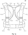
- Fig. 1a shows a schematic front view of a device 100 for detecting electrophysiological signals of a living being (for example animals or humans) and
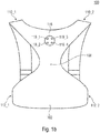
- Figure 1b a schematic rear view of the device 100 for detecting electrophysiological signals of a living being, according to an embodiment of the present invention.
- the device 100 comprises a textile carrier 102, at least two dry electrodes 104_1-104_4, which are attached to an inner side of the textile carrier 102, and at least two belts 106_1-106_2 attached to the textile carrier 102.
- the at least two straps 106_1-106_2 allow the donnable device 100 to be set on a body of the living being and / or a contact pressure of the at least two dry electrodes 104 on a skin of the living being, for example by means of which a quality that can be detected by the at least two dry electrodes 104_1-104_4 physiological signals can be improved.
- the device 100 has four dry electrodes. It should be noted, however, that the invention is not restricted to such exemplary embodiments. Rather, the device 100 can generally have n dry electrodes 104_1-104_n, where n is a natural number greater than or equal to two, n 2, such as two, three, four, five, six or more dry electrodes.
- the textile carrier 102 can be made from a (eg, single) piece of material and shaped in such a way that it has five areas: a middle area 108, two upper areas 110_1-110_2, each extending away from the middle area 108 and two lateral regions 112_1-112_2, each extending away from the central region 108, wherein, when the device 100 is worn by a living being, the central region 108 of the textile carrier 102 extends over a back region of the living being the two upper areas 110_1-110_2 of the textile carrier 102 extend starting from the back area over respective shoulder areas up to the upper chest areas of the living being, and the two lateral areas 112_1-112_2 of the textile carrier 102 starting from the back area over respective axillary lines up to respective upper abdominal areas or lower chest areas.
- the two upper areas 110_1-110_2 of the textile carrier 102 can be connected to the two lateral areas 112_1-112_2 of the textile carrier via two of the at least two straps.
- a first upper area 110_1 of the textile carrier 102 can be connected to a first lower area 112_1 of the textile carrier 102 via a first belt 106_1
- a second upper area 110_2 of the textile carrier 102 can be connected to a second lower area 112_2 via a second belt 106_2 of the textile carrier 102 can be connected.
- the two lateral areas 112_1-112_2 can be connected to one another via a third strap or alternatively via a connecting element such as a Velcro fastener, buckle, clamping strap or snap fastener.
- the at least two dry electrodes can be attached to at least two areas from the two upper areas 110_1-110_2 and the two lateral areas 112_1-112_2 of the textile carrier 102 on an inside of the textile carrier 102.
- a A second dry electrode 104_2 can be attached to a first lower area 112_1 of the textile carrier 102
- a third dry electrode 104_3 to a second upper area of the textile carrier 102
- a fourth dry electrode 104_4 to the second lower area 112_2 of the textile carrier 102.
- the at least two dry electrodes 104_1-104_4 can be connected via insulated lines 114_1-114_4 to a connection 116 attached to an outside of the textile carrier 102, e.g. to provide the electrophysiological signals detected with the at least two dry electrodes.
- the connection 116 can have connection elements 118_1-118_4 which are led to the outside and which are connected to the at least two insulated lines.
- the textile carrier 102 together with the at least two belts 106_1-106_2 can form, for example, the shape of a belt system.
- the belt system can, for example, have the shape of a vest.
- the device 100 shown can be used, for example, for recording an electrocardiogram (EKG) or for monitoring patients with a cardiovascular risk constellation or for monitoring patients in cardiological rehabilitation or for telemedical cardiac monitoring.
- EKG electrocardiogram
- Fig. 1a shows a front view of the device 100 (belt system) and Figure 1b a rear view of the device 100.
- the textile carrier 102 (for example in the form of a vest) consists of a single stretchable piece of material to which the straps 106_1-106_2 are sewn.
- the straps 106_1-106_2 are elastic and have a Velcro fastener so that when they are put on, the electrodes 104_1-104_4 can be adjusted to a tightness and an even contact pressure.
- the electrodes 104_1-104_4 are located on the inside of the belt system. So that the electrodes 104_1-104_4 adhere better to the head, the electrodes have non-slip surfaces. On the outside of the belt system there are contacts 118_1-118_4 on the back for connecting a measuring device (see Figure 1b ).
- FIG. 11 shows an illustration of a front view of the device 100 when it is carried by a doll as a representation for a living being, for example, while Figure 2b shows an illustration of a rear view of the device 100 when this is carried, for example, by a doll as a representation of a living being.
- Fig. 3 shows a schematic view of a dry electrode 104, according to an embodiment of the present invention.
- the dry electrode 104 has a layer 150 made of electrically conductive fabric and a layer 152 made of electrically conductive polymer, which covers the layer 150 made of conductive fabric.
- the requirements placed on the dry electrodes 104 during the EKG measurement are that the resistance of the dry electrodes 104 is low and remains almost constant over time.
- the dry electrodes should adhere well to the patient's skin.
- a combination of materials can be used in exemplary embodiments, as will be explained below.
- a silver-plated knitted fabric can be used as the base material as the electrically conductive material.
- the advantage of this substance is its improved (e.g. high) electrical conductivity, but when washing in open areas of the electrodes, silver particles are washed out. This leads to an increase in the electrical resistance, which leads to a deterioration in the EKG signal.
- this fabric is protected with an electrically conductive polymer, such as a silicone coating, in the exemplary embodiments (see FIG Fig. 3 ). Electrically conductive silicone has a lower conductivity than the silver-plated knitted fabric, but if this is applied in a thin layer (e.g.
- the improved (e.g. high) conductivity of the dry electrode 104 is maintained and at the same time the Dry electrode 104 protected from the washing out of silver particles.
- silicone due to its good elasticity, silicone has good adhesive properties on the skin of a living being (e.g. humans or animals). This combination of materials makes it possible to use the dry electrodes several times and to use them in washable clothing.
- FIG. 10 shows a flow diagram of a method 200 for producing a device 100 for detecting electrophysiological signals, according to an exemplary embodiment of the present invention.
- the method 200 comprises a step 202 of providing a textile carrier.
- the method 200 further comprises a step 204 of forming at least two dry electrodes on an inside of the textile carrier by means of a transfer printing method.
- the method 200 further comprises a step 206 of providing at least two adjustable straps and attaching the at least two adjustable straps to the textile carrier.
- the insulated lines connected to the at least two dry electrodes and (optionally) also the connection connected to the insulated lines can be formed.
- step 204 Preferred exemplary embodiments of step 204 are described in more detail below.
- the transfer printing method can be used in exemplary embodiments.
- transfer printing is used to decorate and seal clothes.
- this method is used to weld all components (dry electrodes, lines, connection) to the base textiles (textile carriers) and to seal electrically conductive materials.
- a multilayer material structure can be used for this purpose, as shown below with reference to FIG Fig. 5 is explained.
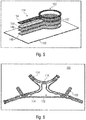
- FIG. 5 Shows in detail Fig. 5 a schematic view of a layer structure (for example multi-layer integration structure) of a dry electrode 104 and a section of a line 114, according to an embodiment of the present invention.
- a layer structure for example multi-layer integration structure
- this layer structure (sandwich structure) can be heated under pressure (eg 170 ° C).
- pressure eg 170 ° C.
- Fig. 6 a schematic view of an inside of the device 100, according to an embodiment of the present invention.
- the dry electrodes 104, insulated lines 114 and an inner part of the connection 116 are attached to an inside of the textile carrier 102.
- the inner part of the connection 116 can realize connections between the insulated lines 114 and the connection elements exposed on the outside of the textile carrier.
- the belts 106 attached to the textile carrier can also be seen.
- Fig. 7 shows a schematic detailed view of an external part of the connection 116 with the connecting elements 118, according to an embodiment of the present invention.
- the connecting elements can be implemented using push buttons or banana sockets, for example.
- Fig. 8 shows a schematic detailed view of an inner part of the connection 116, which realizes the connections between the insulated lines 114 and the connection elements exposed on the outside of the textile carrier.
- the structure of cables described above is waterproof and protects against moisture or sweat during use.
- exemplary embodiments implement one Combination of improved (e.g. best possible) material components for signal acquisition and signal transmission.
- embodiments implement the chosen form of integration of these materials in a textile carrier, the requirements for interference stability.
- embodiments address and mitigate further critical points through the chosen concept (as an adjustable belt system) so that a sufficiently good signal quality can always be provided for different genders, body sizes and body proportions.
- aspects have been described in connection with a device, it goes without saying that these aspects also represent a description of the corresponding method, so that a block or a component of a device is also to be understood as a corresponding method step or as a feature of a method step. Analogously to this, aspects that have been described in connection with or as a method step also represent a description of a corresponding block or details or features of a corresponding device.
- Some or all of the method steps can be carried out by a hardware apparatus (or using a hardware Apparatus), such as a microprocessor, a programmable computer or an electronic circuit. In some embodiments, some or more of the most important process steps can be performed by such an apparatus.
Landscapes
- Health & Medical Sciences (AREA)
- Life Sciences & Earth Sciences (AREA)
- Animal Behavior & Ethology (AREA)
- Veterinary Medicine (AREA)
- Public Health (AREA)
- Engineering & Computer Science (AREA)
- Biomedical Technology (AREA)
- General Health & Medical Sciences (AREA)
- Heart & Thoracic Surgery (AREA)
- Surgery (AREA)
- Physics & Mathematics (AREA)
- Molecular Biology (AREA)
- Medical Informatics (AREA)
- Pathology (AREA)
- Biophysics (AREA)
- Cardiology (AREA)
- Nuclear Medicine, Radiotherapy & Molecular Imaging (AREA)
- Radiology & Medical Imaging (AREA)
- Neurology (AREA)
- Measurement And Recording Of Electrical Phenomena And Electrical Characteristics Of The Living Body (AREA)
Abstract
Ausführungsbeispiele schaffen eine anziehbare Vorrichtung zur Erfassung elektrophysiologischer Signale eines Lebewesens. Die Vorrichtung umfasst einen textilen Träger, zumindest zwei Trockenelektroden, die auf einer Innenseite des textilen Trägers angebracht sind, und zumindest zwei an dem textilen Träger angebrachten, einstellbaren Gurten, die es ermöglichen, die anziehbare Vorrichtung auf einen Körper des Lebewesens und einen Anpressdruck der zumindest zwei Trockenelektroden auf eine Haut des Lebewesens einzustellen.Embodiments provide a wearable device for acquiring electrophysiological signals from a subject. The device comprises a textile carrier, at least two dry electrodes that are attached to the inside of the textile carrier, and at least two adjustable straps that are attached to the textile carrier and allow the wearable device to be placed on a body of the living being and a contact pressure of at least to adjust two dry electrodes to a skin of the living being.
Description
Ausführungsbeispiele der vorliegenden Erfindung beziehen sich auf eine anziehbare Vorrichtung zur Erfassung elektrophysiologischer Signale. Weitere Ausführungsbeispiele beziehen sich auf eine Trockenelektrode zur Erfassung elektrophysiologischer Signale. Weitere Ausführungsbeispiele beziehen sich auf ein Verfahren zur Herstellung einer anziehbaren Vorrichtung zur Erfassung elektrophysiologischer Signale.Embodiments of the present invention relate to a wearable device for detecting electrophysiological signals. Further exemplary embodiments relate to a dry electrode for recording electrophysiological signals. Further exemplary embodiments relate to a method for producing a wearable device for detecting electrophysiological signals.
Für die Erfassung elektrophysiologischer Signale an Lebewesen, wie z.B. am menschlichen Körper, ist eine gute Kontaktierung der primäre Messwertaufnehmer (z.B. Elektroden) notwendig, damit eine gute Signalqualität erzielt werden kann. Darüber hinaus muss diese Adaption auch eine ausreichende Robustheit aufweisen, da bei Signalerfassung im Alltag und unter Bewegung sonst Störungen durch nicht gleichmäßig anliegende Elektroden auftreten (Bewegungsartefakte).For the acquisition of electrophysiological signals on living beings, e.g. on the human body, good contacting of the primary transducers (e.g. electrodes) is necessary so that a good signal quality can be achieved. In addition, this adaptation must also be sufficiently robust, since during signal acquisition in everyday life and when moving, otherwise disturbances occur due to electrodes that are not evenly attached (movement artifacts).
Wird die Signalverarbeitungskette genauer betrachtet, so sind für die Signalerfassung vom Körper bis zu einer Auswerteelektronik verschiedene Funktionsblöcke miteinander verknüpft:
- ▪ der Elektrodenbereich muss leitfähig sei und einen möglichst geringen Widerstand aufweisen, um die physiologischen Signale in guter Qualität aufzunehmen,
- ▪ der Leitungsabschnitt soll die aufgenommenen Messwerte möglichst störungsfrei bis zur Kontaktierungsstelle mit der Auswerteelektronik übertragen, und
- ▪ alle verwendeten Komponenten und Materialien sollen einen hohen Tragekomfort und Biokompatibilität aufweisen.,
- ▪ the electrode area must be conductive and have the lowest possible resistance in order to receive the physiological signals in good quality,
- ▪ the line section should transmit the recorded measured values as smoothly as possible to the contacting point with the evaluation electronics, and
- ▪ All components and materials used should be extremely comfortable and biocompatible.,
Im Sinne einer guten Adaption sollen die Messwertaufnehmer auch bei unterschiedlichen Körpergrößen, unterschiedlichen Körperproportionen und für verschiedene Geschlechter eine gute Signalerfassung gewährleisten. Daher müssen textile Trägersysteme mit integrierten Messwertaufnehmern (z.B. Shirt oder Weste oder Gurt) diesen anatomischen Anforderungen Rechnung tragen.In terms of good adaptation, the measured value recorders should ensure good signal detection even with different body sizes, different body proportions and for different genders. Therefore, textile carrier systems with integrated measurement sensors (e.g. shirt or vest or belt) must take these anatomical requirements into account.
Bei der Erfassung elektrophysiologischer Signale am Körper werden im klinischen Alltag typischerweise Silber-Silberchlorid-Klebeelektroden (Ag/AgCI) verwendet. Diese Art vonWhen recording electrophysiological signals on the body, silver-silver chloride adhesive electrodes (Ag / AgCI) are typically used in everyday clinical practice. This kind of
Elektroden verfügen über einen Kleberand (ähnlich wie bei einem Pflaster) und einen leitfähigen Kern, der zusätzlich mit einem Kontaktgel ausgeführt ist, damit ein geringer Haut-Elektroden-Widerstand erreicht werden kann.Electrodes have an adhesive edge (similar to a plaster) and a conductive core, which is also made with a contact gel, so that a low skin-electrode resistance can be achieved.
Diese Elektroden haben jedoch die folgenden Nachteile:
- ▪ Beim Anlegen der Elektroden fühlt sich das Gel für die zu vermessenden Personen unangenehm an.
- ▪ Mit längerer Messdauer verliert der Kleberand aufgrund der natürlichen Transpiration seine Klebewirkung, wodurch die Elektroden abfallen können und aufgrund von Signalverlust keine auswertbaren Daten mehr aufgenommen werden können.
- ▪ Bei längerer Anwendung (z.B. 24h-EKG (EKG = Elektrokardiogramm) oder Messung bis zu einer Woche) können Hautirritationen auftreten.
- ▪ When the electrodes are applied, the gel feels uncomfortable for the people to be measured.
- ▪ With a longer measurement period, the adhesive edge loses its adhesive effect due to natural transpiration, which means that the electrodes can fall off and no more evaluable data can be recorded due to a loss of signal.
- ▪ Long-term use (eg 24-hour EKG (EKG = electrocardiogram) or measurement for up to a week) can cause skin irritation.
Seit einigen Jahren werden verschiedene Materialien für Trockenelektroden erforscht, die aufgrund einer hohen Leitfähigkeit den Einsatz von Kontaktgel vermeiden. Diese Trockenelektroden sind in den allermeisten Fällen in textile Trägersysteme eingearbeitet (z.B. Pulsbrustgurt, Sensorshirt, Weste, Gurtsystem). Sensorsysteme für ein Ein-Kanal-EKG können recht einfach umgesetzt werden. Hier werden zwei Elektroden z.B. in einen Brustgurt integriert, der nahezu immer gleichmäßig am Körper anliegt und stabile Signale liefert. An Sensorsysteme zur Aufzeichnung von Mehrkanal-EKGs sind deutliche höhere Anforderungen gestellt, da hier mehrere Elektroden (z.B. vier Elektroden für ein Dreikanal-EKG bzw. sieben Elektroden für ein Neuen-Kanal-EKG bzw. zehn Elektroden für ein zwölf-Kanal-EKG) in das Textil an unterschiedlichen Applikationsstellen zu integrieren sind und dabei immer eine ausreichend gute Adaption gewährleistet werden muss.For some years now, various materials for dry electrodes have been researched that avoid the use of contact gel due to their high conductivity. In the vast majority of cases, these dry electrodes are incorporated into textile carrier systems (e.g. pulse chest belt, sensor shirt, vest, belt system). Sensor systems for a single-channel EKG can be implemented quite easily. Here two electrodes are integrated into a chest strap, for example, which is almost always evenly attached to the body and delivers stable signals. Significantly higher requirements are placed on sensor systems for recording multi-channel EKGs, as there are several electrodes (e.g. four electrodes for a three-channel EKG or seven electrodes for a new-channel EKG or ten electrodes for a twelve-channel EKG) must be integrated into the textile at different application points and a sufficiently good adaptation must always be guaranteed.
Dabei müssen die textilen Träger immer auch den schon oben erwähnten anatomischen Anforderungen der Trägerinnen oder Träger gerecht werden (z.B. Geschlecht, Größe, Proportionen, Einschränkungen).The textile wearer must always meet the above-mentioned anatomical requirements of the wearer (e.g. gender, size, proportions, restrictions).
Nachteile bisheriger textilintegrierter Sensorsysteme:
- ▪ Keine ausreichend gute Signale wegen zu schlechter Elektrodenmaterialien.
- ▪ Keine ausreichend gute Signale wegen zu geringer Adaption (z.B. kein ausreichend hoher Anpressdruck).
- ▪ Keine ausreichend guten Signale wegen Bewegungsartefakten.
- ▪ Verwendete Konstruktion und Materialien nicht waschbar, keine Aufbereitung möglich.
- ▪ Keine Langzeitstabilität der Signalqualität (Leitwert des Elektrodenmaterials nimmt ab, z.B. bei Waschvorgängen) Qualität der.
- ▪ Spezifische Ausführung für Frauen und Männer notwendig.
- ▪ Viele verschiedene Konfektionsgrößen notwendig.
- ▪ Sensorsystem zu auffällig und daher nicht akzeptiert.
- ▪ Sensorsystem unkomfortabel im Alltag zu tragen.
- ▪ Sensorsystem unkomfortabel bei Schlafanalyse zu tragen.
- ▪ Sensorsystem nicht einstellbar.
- ▪ Sensorsystem nicht allein anziehbar.
- ▪ Sensorsystem führt zu starken Einschränkungen bei der Kleiderwahl.
- ▪ No sufficiently good signals due to poor electrode materials.
- ▪ No sufficiently good signals due to insufficient adaptation (eg insufficient contact pressure).
- ▪ No sufficiently good signals due to movement artifacts.
- ▪ Construction and materials used cannot be washed, processing is not possible.
- ▪ No long-term stability of the signal quality (conductivity of the electrode material decreases, e.g. during washing processes).
- ▪ Specific design required for women and men.
- ▪ Many different clothing sizes required.
- ▪ Sensor system too conspicuous and therefore not accepted.
- ▪ Sensor system uncomfortable to wear in everyday life.
- ▪ Sensor system uncomfortable to wear during sleep analysis.
- ▪ Sensor system not adjustable.
- ▪ Sensor system cannot be worn alone.
- ▪ Sensor system leads to severe restrictions in the choice of clothes.
Ein wichtiger Punkt beim Monitoring im Alltag ist die ausreichende Akzeptanz und gute Anwendbarkeit durch die Nutzer. Die Anwender müssen die textilen Trägersysteme einfach anlegen und im Alltag jederzeit schnell und unkompliziert anpassen können.An important point in everyday monitoring is sufficient acceptance and good usability by users. Users have to put on the textile carrier systems easily and be able to adjust them quickly and easily in everyday life at any time.
Der vorliegenden Erfindung liegt daher die Aufgabe zugrunde die bestehende Situation zu verbessern.The present invention is therefore based on the object of improving the existing situation.
Diese Aufgabe wird durch die unabhängigen Patentansprüche gelöst.This problem is solved by the independent patent claims.
Vorteilhafte Weiterbildungen finden sich in den abhängigen Patentansprüchen.Advantageous further developments can be found in the dependent claims.
Ausführungsbeispiele schaffen eine anziehbare Vorrichtung zur Erfassung elektrophysiologischer Signale eines Lebewesens [z.B. Tieres oder Menschen [z.B. menschlichen Patienten]]. Die Vorrichtung umfasst einen textilen Träger, zumindest zwei Trockenelektroden [z.B. zwei, drei oder vier Trockenelektroden], die auf einer Innenseite des textilen Trägers angebracht sind, und zumindest zwei an dem textilen Träger angebrachten, einstellbaren Gurten, die es ermöglichen, die anziehbare Vorrichtung auf einen Körper des Lebewesens und einen Anpressdruck der zumindest zwei Trockenelektroden auf eine Haut des Lebewesens einzustellen.Embodiments provide a wearable device for detecting electrophysiological signals from a living being [e.g. Animal or human [e.g. human patients]]. The device comprises a textile support, at least two dry electrodes [e.g. two, three or four dry electrodes], which are attached to an inside of the textile carrier, and at least two adjustable straps attached to the textile carrier, which allow the device to be put on a body of the living being and a contact pressure of the at least two dry electrodes to adjust a skin of the living being.
Bei Ausführungsbeispielen können die zumindest zwei Trockenelektroden zumindest vier Trockenelektroden zur Erfassung eines mehrkanaligen Elektrokardiogramms des Lebewesens sein.In exemplary embodiments, the at least two dry electrodes can be at least four dry electrodes for recording a multi-channel electrocardiogram of the living being.
Bei Ausführungsbeispielen kann der textile Träger aus einem [z.B. einzigen] Materialstück gefertigt sein.In embodiments, the textile support can be made from a [e.g. single] piece of material.
Bei Ausführungsbeispielen kann der textile Träger zusammen mit den zumindest zwei Gurten die Form eines Gurtsystems bilden.In exemplary embodiments, the textile carrier, together with the at least two belts, can form the shape of a belt system.
Bei Ausführungsbeispielen kann der textile Träger einen mittleren Bereich, zwei obere Bereiche, die sich jeweils von dem mittleren Bereich weg erstrecken, und zwei seitliche Bereiche, die sich jeweils von dem mittleren Bereich weg erstrecken, aufweisen.In exemplary embodiments, the textile carrier can have a central area, two upper areas, which each extend away from the central area, and two lateral areas, which each extend away from the central area.
Bei Ausführungsbeispielen kann sich, wenn die Vorrichtung von dem Lebewesen getragen wird, der mittlere Bereich des textilen Trägers über einen Rückenbereich des Lebewesen erstreckt, die zwei oberen Bereiche des textilen Trägers ausgehend von dem Rückenbereich über jeweilige Schulterbereiche bis hin zu oberen Brustbereichen des Lebewesen erstrecken, und die zwei seitlichen Bereiche des textilen Trägers ausgehend von dem Rückenbereich über jeweilige Axillarlinien bis hin zu jeweiligen oberen Bauchbereichen oder unteren Brustbereichen erstrecken.In embodiments, when the device is worn by the living being, the middle area of the textile carrier extends over a back area of the living being, the two upper areas of the textile carrier extending from the back area over respective shoulder areas to the upper chest areas of the living being, and the two lateral areas of the textile carrier extend starting from the back area over respective axillary lines up to respective upper abdominal areas or lower chest areas.
Bei Ausführungsbeispielen können die zwei oberen Bereiche des textilen Trägers mit den zwei seitlichen Bereichen des textilen Trägers über zwei der zumindest zwei Gurte verbindbar sein.In embodiments, the two upper areas of the textile carrier can be connected to the two lateral areas of the textile carrier via two of the at least two straps.
Bei Ausführungsbeispielen können die zwei seitlichen Bereiche des textilen Trägers über ein Verbindungselement [z.B. Klettverschluss, Steckschnalle, Klemmriemen oder Druckknopf] miteinander verbindbar sein.In embodiments, the two lateral areas of the textile carrier can be connected via a connecting element [e.g. Velcro fastener, buckle, clamping strap or push button] can be connected to one another.
Bei Ausführungsbeispielen können die zwei seitlichen Bereiche des textilen Trägers über einen dritten Gurt der zumindest zwei Gurte miteinander verbindbar sein.In embodiments, the two lateral areas of the textile carrier can be connected to one another via a third strap of the at least two straps.
Bei Ausführungsbeispielen können die zumindest zwei Trockenelektroden an zumindest zwei Bereichen aus den zwei oberen Bereichen und den zwei seitlichen Bereichen des textilen Trägers an dem textilen Träger angebracht sein.In embodiments, the at least two dry electrodes can be attached to the textile carrier in at least two areas from the two upper areas and the two lateral areas of the textile carrier.
Bei Ausführungsbeispielen können die zumindest zwei Trockenelektroden zumindest vier Trockenelektroden sein, wobei zwei Trockenelektroden der zumindest vier Trockenelektroden auf einer Innenseite der zwei oberen Bereiche des textilen Trägers angebracht sind, wobei zwei andere Trockenelektroden der zumindest vier Trockenelektroden auf einer Innenseite der zwei seitlichen Bereiche des textilen Trägers angebracht sind.In embodiments, the at least two dry electrodes can be at least four dry electrodes, two dry electrodes of the at least four dry electrodes being attached to an inside of the two upper areas of the textile carrier, with two other dry electrodes of the at least four dry electrodes on an inside of the two lateral areas of the textile carrier are attached.
Bei Ausführungsbeispielen können die zwei Trockenelektroden, wenn die Vorrichtung von dem Lebewesen getragen wird, Schlüsselbeinbereiche [z.B. einen linken und rechten Schlüsselbeinbereich] oder obere Bereiche oberhalb eines Brustbereich des Lebewesens kontaktieren.In embodiments, when the device is worn by the living being, the two dry electrodes can contact clavicle areas [eg left and right clavicle areas] or upper areas above a chest area of the living being.
Bei Ausführungsbeispielen können die zwei anderen Trockenelektroden, wenn die Vorrichtung von dem Lebewesen getragen wird, abdominale Bereiche [z.B. innerhalb eines abdominalen Quadranten] oder untere Bereiche unterhalb eines Brustbereichs des Lebewesens kontaktieren.In embodiments, when the device is worn by the living being, the two other dry electrodes may include abdominal areas [e.g. within an abdominal quadrant] or lower areas below a chest area of the living being.
Bei Ausführungsbeispielen können der textile Träger und/oder die zumindest zwei Gurte elastisch sein.In embodiments, the textile carrier and / or the at least two straps can be elastic.
Bei Ausführungsbeispielen können die zumindest zwei Trockenelektroden jeweils eine Schicht aus leitfähigem Gewebe [z.B. versilbertem Gewebe] und eine Schicht aus elektrisch leitfähigem Polymer [z.B. Silikon], die die Schicht aus leitfähigem Gewebe bedeckt, aufweisen.In embodiments, the at least two dry electrodes can each have a layer of conductive fabric [e.g. silver-plated fabric] and a layer of electrically conductive polymer [e.g. Silicone], which covers the layer of conductive fabric.
Bei Ausführungsbeispielen kann die Schicht aus elektrisch leitfähigem Polymer dünner sein als 1 mm.In embodiments, the layer of electrically conductive polymer can be thinner than 1 mm.
Bei Ausführungsbeispielen können [z.B. verschiedene] Schichten der zumindest zwei Trockenelektroden mittels einer Kombination aus einem Siebdruckverfahren [z.B. zum Vorbereiten der einzelnen Funktionsschichten] und einem Transferdruckverfahren [z.B. zum Packaging = Zusammenschweißen und Integration in den textilen Träger] gebildet sein.In embodiments, [e.g. different] layers of the at least two dry electrodes by a combination of a screen printing process [e.g. for preparing the individual functional layers] and a transfer printing process [e.g. for packaging = welding together and integration into the textile carrier].
Bei Ausführungsbeispielen können die zumindest zwei Trockenelektroden über isolierte Leitungen mit einem an einer Außenseite des textilen Trägers angebrachten Anschluss [z.B. zum Bereitstellen der mit den zumindest zwei Trockenelektroden erfassten elektrophysiologischen Signale] verbunden sein.In exemplary embodiments, the at least two dry electrodes can be connected via insulated lines with a connection [e.g. for providing the electrophysiological signals detected with the at least two dry electrodes].
Bei Ausführungsbeispielen können die isolierten Leitungen jeweils eine Schicht aus leitfähigem Gewebe und zumindest eine Schicht aus Isolationsmaterial [z.B. nur Deckschicht oder auch Grund- und Deckschicht], die die Schicht aus leitfähigem Gewebe bedeckt, aufweisen.In embodiments, the insulated lines may each have a layer of conductive fabric and at least one layer of insulating material [e.g. only top layer or also base and top layer], which covers the layer of conductive fabric.
Bei Ausführungsbeispielen können Schichten der isolierten Leitungen mittels einer Kombination aus einem Siebdruckverfahren und einem Transferdruckverfahren gebildet sein.In exemplary embodiments, layers of the insulated lines can be formed by means of a combination of a screen printing process and a transfer printing process.
Bei Ausführungsbeispielen können die isolierten Leitungen jeweils mit einem nach außen geführten Anschlusselement [z.B. Druckknopf, Bananenbuchse] des Anschlusses verbunden sein.In exemplary embodiments, the insulated lines can each be connected to a connection element [for example push button, banana socket] of the connection that is led to the outside.
Bei Ausführungsbeispielen kann der Anschluss zumindest eine Schicht aus Isolationsmaterial [z.B. nur Deckschicht oder auch Grund- und Deckschicht] aufweisen, wobei eine Schicht aus der zumindest einen Schicht aus Isolationsmaterial in Bereichen der Anschlusselemente geöffnet ist, so dass die Anschlusselemente frei liegen.In embodiments, the connector can include at least one layer of insulating material [e.g. only cover layer or also base and cover layer], a layer of the at least one layer of insulation material being opened in areas of the connection elements so that the connection elements are exposed.
Weitere Ausführungsbeispiele schaffen eine Trockenelektrode zur Erfassung elektrophysiologischer Signale eines Lebewesens. Die Trockenelektrode umfasst eine Schicht aus leitfähigem Gewebe [z.B. versilbertem Gewebe], und einer Schicht aus elektrisch leitfähigem Polymer [z.B. Silikon], die die Schicht aus leitfähigem Gewebe bedeckt.Further exemplary embodiments create a dry electrode for detecting electrophysiological signals from a living being. The dry electrode comprises a layer of conductive fabric [e.g. silver-plated fabric], and a layer of electrically conductive polymer [e.g. Silicone], which covers the layer of conductive fabric.
Bei Ausführungsbeispielen kann das leitfähige Gewebe ein versilbertes Gewebe sein.In exemplary embodiments, the conductive fabric can be a silver-plated fabric.
Bei Ausführungsbeispielen kann die Schicht aus elektrisch leitfähigem Polymer [z.B. Silikon] eine Dicke von Weniger als 1 mm aufweisen.In embodiments, the layer of electrically conductive polymer [e.g. Silicone] have a thickness of less than 1 mm.
Bei Ausführungsbeispielen kann die Trockenelektrode ferner eine thermoplastische Polyurethanfolie aufweisen, wobei die Schicht aus leitfähigem Gewebe auf der thermoplastischen Polyurethanfolie angeordnet ist.In exemplary embodiments, the dry electrode can furthermore have a thermoplastic polyurethane film, the layer of conductive fabric being arranged on the thermoplastic polyurethane film.
Bei Ausführungsbeispielen kann die Trockenelektrode in einem Transferdruckfolienschichtsystem aus zumindest zwei Transferdruckfolien eingebettet sein, wobei das Transferdruckfolienschichtsystem in einem zu der Schicht aus elektrisch leitfähigem Polymer [z.B. Silikon] benachbarten Bereich teilweise geöffnet ist, so dass die Schicht aus elektrisch leitfähigem Polymer teilweise freiliegt.In exemplary embodiments, the dry electrode can be embedded in a transfer printing film layer system composed of at least two transfer printing films, the transfer printing film layer system being embedded in one of the layers of electrically conductive polymer [e.g. Silicone] adjacent area is partially open, so that the layer of electrically conductive polymer is partially exposed.
Bei Ausführungsbeispielen kann die Trockenelektrode mittels eines Transferdruckverfahrens auf einem textilen Träger angebracht sein.In embodiments, the dry electrode can be attached to a textile carrier by means of a transfer printing process.
Weitere Ausführungsbeispiele schaffen ein Verfahren zur Herstellung einer anziehbaren Vorrichtung zur Erfassung elektrophysiologischer Signale eines Lebewesens. Das Verfahren umfasst einen Schritt des Bereitstellens eines textilen Trägers. Ferner umfasst das Verfahren einen Schritt des Bildens von zumindest zwei Trockenelektroden auf einer Innenseite des textilen Trägers mittels eines Transferdruckverfahrens. Ferner umfasst das Verfahren einen Schritt des Bereitstellen von zumindest zwei einstellbaren Gurten und Anbringen der zumindest zwei einstellbaren Gurte an den textilen Träger.Further exemplary embodiments provide a method for producing a wearable device for detecting electrophysiological signals of a living being. The method comprises a step of providing a textile carrier. The method further comprises a step of forming at least two dry electrodes on an inside of the textile carrier by means of a transfer printing method. The method further comprises a step of providing at least two adjustable straps and attaching the at least two adjustable straps to the textile carrier.
Bei Ausführungsbeispielen kann das Bilden der zumindest zwei Trockenelektroden einen Schritt des Bereitstellens einer Schicht aus elektrisch leitfähigem Gewebe [z.B. versilbertem Gewebe], und einen Schritt des Bereitstellens einer Schicht aus elektrisch leitfähigem Polymer [z.B. Silikon] auf der Schicht aus elektrisch leitfähigem Gewebe, so dass die Schicht aus elektrisch leitfähigem Polymer die Schicht aus elektrisch leitfähigem Gewebe zumindest teilweise bedeckt, aufweisen.In embodiments, forming the at least two dry electrodes can include a step of providing a layer of electrically conductive fabric [e.g. silver-plated fabric], and a step of providing a layer of electrically conductive polymer [e.g. Silicone] on the layer of electrically conductive fabric, so that the layer of electrically conductive polymer at least partially covers the layer of electrically conductive fabric.
Bei Ausführungsbeispielen kann das Bilden der zumindest zwei Trockenelektrode ferner einen Schritt des Bereitstellens einer thermoplastischen Polyurethanfolie aufweisen, wobei die Schicht aus leitfähigem Gewebe auf der thermoplastischen Polyurethanfolie angeordnet ist.In embodiments, the formation of the at least two dry electrodes can further include a step of providing a thermoplastic polyurethane film, the layer of conductive fabric being arranged on the thermoplastic polyurethane film.
Bei Ausführungsbeispielen kann das Bilden der zumindest zwei Trockenelektroden ferner einen Schritt des Bereitstellens einer ersten Transferdruckfolie und einer zweiten Transferdruckfolie aufweisen, wobei die Schicht aus elektrisch leitfähigem Polymer und die Schicht aus elektrisch leitfähigem Gewebe zwischen der ersten Transferdruckfolie und der zweiten Transferdruckfolie angeordnet sind, wobei die erste Transferdruckfolie auf der Schicht aus elektrisch leitfähigem Polymer angeordnet ist, wobei die erste Transferdruckfolie in einem zu der Schicht aus elektrisch leitfähigem Polymer benachbarten Bereich teilweise geöffnet ist, so dass die Schicht aus elektrisch leitfähigem Polymer teilweise freiliegt.In embodiments, the formation of the at least two dry electrodes can further include a step of providing a first transfer printing film and a second transfer printing film, wherein the layer of electrically conductive polymer and the layer of electrically conductive fabric are arranged between the first transfer printing film and the second transfer printing film, the The first transfer printing film is arranged on the layer of electrically conductive polymer, the first transfer printing film being partially open in an area adjacent to the layer of electrically conductive polymer, so that the layer of electrically conductive polymer is partially exposed.
Bei Ausführungsbeispielen können die die Schicht aus elektrisch leitfähigem Polymer und die Schicht aus elektrisch leitfähigem Gewebe mittels des Transferdruckverfahrens zwischen der ersten Transferdruckfolie und der zweiten Transferdruckfolie eingebettet werden.In embodiments, the layer of electrically conductive polymer and the layer of electrically conductive fabric can be embedded between the first transfer printing film and the second transfer printing film by means of the transfer printing process.
Bei Ausführungsbeispielen können bei dem Bilden der zumindest zwei Trockenelektroden ferner zumindest zwei isolierte Leitungen gebildet werden.In embodiments, when the at least two dry electrodes are formed, at least two insulated lines can also be formed.
Bei Ausführungsbeispielen kann das Verfahren ferner einen Schritt des Bildens eines Anschlusses [z.B. zum Bereitstellen der mit den zumindest zwei Trockenelektroden erfassten elektrophysiologischen Signale] an einer Außenseite des textilen Trägers aufweisen, wobei der Anschluss mit den zumindest zwei isolierten Leitungen verbunden ist.In embodiments, the method may further include a step of forming a port [e.g. for providing the electrophysiological signals detected with the at least two dry electrodes] on an outside of the textile carrier, the connection being connected to the at least two insulated lines.
Bei Ausführungsbeispielen können bei dem Bilden des Anschlusses nach außen geführte Anschlusselemente [z.B. Druckknöpfe oder Bananenbuchsen] gebildet werden, die mit jeweils einer der zumindest zwei isolierten Leitungen verbunden sind.In exemplary embodiments, when the connection is formed, connection elements [for example push buttons or banana sockets] which are led to the outside and which are each connected to one of the at least two insulated lines can be formed.
Bei Ausführungsbeispielen kann bei dem Bilden des Anschlusses eine weitere Transferdruckfolie bereitgestellt werden, wobei die weitere Transferdruckfolie in Bereichen der nach außen geführten Anschlusselementen geöffnet ist, so dass die Anschlusselemente freiliegen, wobei die weitere Transferdruckfolie mittels eines Transferdruckverfahrens an der Außenseite des textilen Trägers angebracht wird, um den Anschluss zu bilden.In exemplary embodiments, a further transfer printing film can be provided when the connection is formed, the further transfer printing film being opened in areas of the connection elements led to the outside, so that the connection elements are exposed, the further transfer printing film being attached to the outside of the textile carrier by means of a transfer printing process, to form the connection.
Weitere Ausführungsbeispiele schaffen ein Verfahren zur Erfassung eines mehrkanaligen Elektrokardiogramms eines Lebewesens mit einer anziehbaren Vorrichtung mit zumindest vier Trockenelektroden gem. einem der hierin beschriebenen Ausführungsbeispiele. Das Verfahren umfasst einen Schritt des Einkoppelns eines Referenzsignals in das Lebewesen mit einer Trockenelektrode der zumindest vier Trockenelektroden der anziehbaren Vorrichtung. Das Verfahren umfasst ferner einen Schritt des Erfassens von zumindest drei elektrophysiologischen Signalen des Lebewesens mittels zumindest drei anderen Trockenelektroden der zumindest vier Trockenelektroden der anziehbaren Vorrichtung, um das mehrkanalige Elektrokardiogramm zu erhalten [z.B. mittels Verarbeiten der erfassten zumindest drei elektrophysiologischen Signalen].Further exemplary embodiments create a method for acquiring a multi-channel electrocardiogram of a living being with a wearable device with at least four dry electrodes according to one of the exemplary embodiments described herein. The method comprises a step of coupling a reference signal into the living being with a dry electrode of the at least four dry electrodes of the wearable device. The method further comprises a step of acquiring at least three electrophysiological signals from the living being using at least three other dry electrodes of the at least four dry electrodes of the wearable device to obtain the multi-channel electrocardiogram [e.g. by processing the acquired at least three electrophysiological signals].
Hierin beschriebene Ausführungsbeispiele schaffen einen textilen Träger, mit dem sowohl die oben beschriebenen Zielsetzungen hinsichtlich stabiler, komfortabler Signalerfassung physiologischer Parameter im Alltag und mobilen Einsatz umsetzen lassen, dabei aber ohne die Nachteile bisheriger Technologien realisiert werden können.Embodiments described herein create a textile carrier with which both the above-described objectives with regard to stable, comfortable signal acquisition of physiological parameters in everyday life and mobile use can be implemented, but without the disadvantages of previous technologies.
Ein erster Aspekt bezieht sich auf einen textilen Träger mit einem einstellbares Gurtsystem, das ähnlich wie eine Weste angezogen bzw. ein Rucksack aufgesetzt werden kann. Bei Ausführungsbeispielen lassen sich die Gurte z.B. über ein System aus Klettverschlüssen an beiden Schultern sowie am Bauch jederzeit auf die Körpergröße und Körperproportionen der Anwenderin oder des Anwenders anpassen. Durch die Anpassung des Gurtsystems wird vor allem die Adaption der primären Messwertaufnehmer (EKG-Elektroden) beeinflusst, sodass immer ein ausreichend guter Haut-Elektroden-Kontakt und damit eine hohe Signalqualität. Die Einstellung muss nicht vor dem Anlegen des textilen Trägers erfolgen (wie z.B. die Einstellschnalle bei einem Pulsbrustgurt zur initialen Weitenänderung), sondern kann auch in der Phase der Datenerfassung immer wieder auf die Aktivitäten und Bedürfnisse des Trägers angepasst werden. Aufgrund des Schnittmusters (keine Stoffpartien vorne am Brustkorb) ist das Trägertextil implizit für Frauen und Männer geeignet. Sowohl die Einstellbarkeit auf die aktuelle Situation und Tätigkeit als auch die Konzeption als geschlechterunabhängiges Textil, unterstützen die Zielerreichung einer kontinuierlich guten Adaption und damit einer hohen Signalqualität bei der Signalerfassung im Alltag (auch über verschiedene Phasen Im tagesverlauf hinweg).A first aspect relates to a textile carrier with an adjustable belt system that can be put on like a vest or a rucksack. In exemplary embodiments, the straps can be adjusted to the user's body size and proportions at any time, for example by means of a system of Velcro fasteners on both shoulders and on the stomach. The adaptation of the belt system mainly influences the adaptation of the primary measurement sensors (EKG electrodes), so that there is always a sufficiently good skin-electrode contact and thus a high signal quality. The setting does not have to be made before the textile wearer is put on (such as the adjustment buckle on a heart rate chest belt to initially change the width), but can also be adapted to the wearer's activities and needs again and again during the data acquisition phase. Due to the pattern (no pieces of fabric on the front of the chest), the carrier textile is implicitly suitable for women and men. Both the adjustability to the current situation and activity as well as the conception as a gender-independent textile support the target achievement of a continuously good adaptation and thus a high one Signal quality when recording signals in everyday life (also across different phases in the course of the day).
Ein zweiter Aspekt, welcher die Zielsetzung einer guten Signalqualität unterstützt, bezieht sich auf eine geschickte Auswahl und Kombination von jeweils den am besten geeigneten Materialien für die Signalerfassung, Signalübertragung und Störunterdrückung. Die Übertragungsstrecke von den primären Messwertaufnehmern hin zur Kontaktierungsstelle für die Auswerteelektronik gliedert sind in folgende Funktionsblöcke:
- ▪ Elektrodenmaterial, das in direktem Kontakt mit der Hautoberfläche steht und die physiologischen Parameter aufnimmt. Die Elektroden sollen hohen Leitwert, einen ausgeprägten Hafteffekt auf der Hautoberfläche (kein Wegrutschten bei Bewegungen) und Biokompatibilität aufweisen.
- ▪ Die Messleitung soll die aufgenommenen Signale verlustfrei und störungsarm übertragen. Das bedeutet, dass das verwendete Material und die aufgebaute Struktur einen hohen Leitwert, eine ausreichen Dehnbarkeit und geringe Widerstandänderung bei mechanischer Beeinflussung aufweisen muss.
- ▪ Die Isolationsschicht schützt das erfasste Signal in der Messleitung vor Störeinkopplungen.
- ▪ Electrode material that is in direct contact with the skin surface and that records the physiological parameters. The electrodes should have a high conductivity, a pronounced adhesive effect on the skin surface (no slipping when moving) and biocompatibility.
- ▪ The measuring line should transmit the recorded signals without loss and with little interference. This means that the material used and the structure built up must have a high conductance, sufficient ductility and little change in resistance in the event of mechanical influences.
- ▪ The insulation layer protects the recorded signal in the measuring line from interference.
Für alle Komponenten gilt, dass die geforderten Eigenschaften durch die chemischen und mechanischen Einflüsse beim Waschen nicht verändert werden dürfen.For all components, the required properties must not be changed by the chemical and mechanical influences during washing.
Ein dritter Aspekt zur Verbesserung der Qualität erfasster Signale bezieht sich auf die Art und Weise der Integration der ausgewählten Materialien in das textile Trägersystem. Bei Ausführungsbeispielen werden Elektrodenmaterial, Messleitung und Isolationsschicht in einem mehrschichtigen Strukturaufbau eingebracht:
- ▪ Die unterste Schicht direkt auf dem Trägertextil ist zum einen untere Isolationsebene und zugleich die Trägerfläche für das gesamte System aus Messwertaufnehmer und Messleitung (unterer Mantel).
- ▪ Die zweite Schicht ist ein leitfähiges Material (Kern).
- ▪ Die dritte Schicht ist ein elektrisch leitfähiges und hautfreundliches Silikon, das nur lokal bei der Elektrodenfläche platziert wird. Damit das darunterliegende leitfähige Material vor Auswaschung geschützt und zugleich eine gute Signalübertragung von Haut zu Silikon zu Messleitung gebildet wird (Elektrode).
- ▪ Die vierte Schicht ist die obere Isolationsschicht, die bis auf die Elektrodenfläche (bereits durch die dritte Schicht abgedeckt) alle Bereiche der noch offenen Messleitung abdeckt (oberer Mantel).
- ▪ The bottom layer directly on the carrier textile is, on the one hand, the lower insulation level and, at the same time, the carrier surface for the entire system of sensor and measuring line (lower jacket).
- ▪ The second layer is a conductive material (core).
- ▪ The third layer is an electrically conductive and skin-friendly silicone that is only placed locally on the electrode surface. So that the conductive material underneath is protected from being washed out and, at the same time, good signal transmission from the skin to the silicone to the measuring line is formed (electrode).
- ▪ The fourth layer is the upper insulation layer, which covers all areas of the open measuring line except for the electrode surface (already covered by the third layer) (upper jacket).
Die aus den beiden Mantelflächen aufgebaute Struktur erfüllt im textilen Trägersystem folgende drei Aufgaben:
- ▪ Elektrische Isolation und Schutz der erfassten Signale und damit Vermeidung von Störsignalen und Kurzschlüssen.
- ▪ Mechanische Stabilisierung der Messleitung und Reduzierung von Bewegungsartefakten.
- ▪ Schutz des leitfähigen Materials vor Auswaschen und damit Erhaltung der physikalischen Materialeigenschaften.
- ▪ Electrical isolation and protection of the recorded signals and thus avoidance of interference signals and short circuits.
- ▪ Mechanical stabilization of the measuring line and reduction of movement artifacts.
- ▪ Protection of the conductive material from being washed out and thus preservation of the physical material properties.
Zur erweiterten Dehnbarkeit der Messleitungen bei Bewegungen des Anwenders, können diese in einer Mäanderstruktur ausgeführt sein. Beim Dehnen und Stauchen findet dann eine geringere mechanische Belastung und damit eine geringe Widerstandsmodulation statt.To increase the flexibility of the measuring lines when the user moves, they can be designed in a meandering structure. When stretching and compressing, there is then less mechanical stress and thus less resistance modulation.
Ausführungsbeispiele schaffen einen textilen Träger, der die oben beschriebenen Merkmale in der folgenden Art und Weise zusammenführt:
- ▪ Kombination geeigneter Werkstoffe für ein Sensorsystem mit Trockenelektroden mit hohem Tragekomfort und verbesserter (z.B. bestmöglicher) Signalqualität.
- ▪ Konzeption eines einstellbaren textilen Trägers für flexible und verbesserter (z.B. guter Adaption).
- ▪ Integration der Funktionskomponenten für verbesserte (z.B. höchste) Störstabilität und geringer Artefaktanfälligkeit.
- ▪ Ergänzend weist das entwickelte Trägersystem eine einfache Handhabung, flexible Anpassung, Unauffälligkeit und hohen Tragekomfort auf, so dass von einer hohen Nutzerakzeptanz und damit sowohl anwendungsbezogenen Verbesserungen als auch kommerziellen Erfolgen zu rechnen ist.
- ▪ Combination of suitable materials for a sensor system with dry electrodes with high wearing comfort and improved (eg best possible) signal quality.
- ▪ Conception of an adjustable textile carrier for flexible and improved (eg good adaptation).
- ▪ Integration of the functional components for improved (eg highest) interference stability and low susceptibility to artifacts.
- ▪ In addition, the carrier system that has been developed is easy to use, flexibly adapted, inconspicuous and is extremely comfortable to wear, so that a high level of user acceptance and thus both application-related improvements and commercial success can be expected.
Bei Ausführungsbeispielen erzeugen die verwendeten Materialien eine Signalübertragungskette, mit der verbesserte (z.B. bestmögliche) Signalqualitäten erzielt werden können.In exemplary embodiments, the materials used generate a signal transmission chain with which improved (e.g. best possible) signal qualities can be achieved.
Bei Ausführungsbeispielen ermöglicht das Konzept des Trägertextils eine individuelle und zeitliche flexible Anpassbarkeit, so dass auch bei unterschiedlichen Personen und Aktivitäten immer eine ausreichend gute Adaption und damit eine gute Signalerfassung gewährleistet ist. Bei Ausführungsbeispielen erzeugt die Art und Weise der Integration eine verbesserte (z.B. gute) Störstabilität und Artefaktstabilität für die Messleitung, Langzeitstabilität über längere Verwendungsdauer beim Monitoring im Alltag (insbesondere hinsichtlich Waschzyklen).In the case of exemplary embodiments, the concept of the carrier textile enables individual and temporally flexible adaptability, so that a sufficiently good adaptation and thus good signal detection is always guaranteed even with different people and activities. In exemplary embodiments, the way of integration creates improved (eg good) interference stability and artifact stability for the measuring line, long-term stability over a longer period of use in everyday monitoring (in particular with regard to washing cycles).
Ausführungsbeispiele der vorliegenden Erfindung finden Anwendung beim medizinischen Monitoring von Patienten mit kardiovaskulärer Risikokonstellation, beim medizinischen Monitoring von Patienten in einer kardiologischen Rehabilitation und beim telemedizinischen Kardio-Monitoring.Embodiments of the present invention are used in the medical monitoring of patients with a cardiovascular risk constellation, in the medical monitoring of patients in cardiological rehabilitation and in telemedical cardio-monitoring.
Ausführungsbeispiele der vorliegenden Erfindung werden bezugnehmend auf die beiliegenden Figuren näher beschrieben. Es zeigen:
- Fig. 1a
- eine schematische Vorderansicht einer Vorrichtung zur Erfassung elektrophysiologischer Signale eines Lebewesens, gemäß einem Ausführungsbeispiel der vorliegenden Erfindung,
- Fig. 1b
- eine schematische Rückansicht der Vorrichtung zur Erfassung elektrophysiologischer Signale eines Lebewesens, gemäß einem Ausführungsbeispiel der vorliegenden Erfindung,
- Fig. 2a
- eine Illustration einer Vorderansicht der Vorrichtung zur Erfassung elektrophysiologischer Signale eines Lebewesens, wenn diese beispielhaft von einer Puppe als Repräsentation für ein Lebewesen getragen wird,
- Fig. 2b
- eine Illustration einer Rückansicht der Vorrichtung zur Erfassung elektrophysiologischer Signale eines Lebewesens, wenn diese beispielhaft von einer Puppe als Repräsentation für ein Lebewesen getragen wird,
- Fig. 3
- eine schematische Ansicht einer Trockenelektrode, gemäß einem Ausführungsbeispiel der vorliegenden Erfindung,
- Fig. 4
- ein Flussdiagramm eines Verfahrens zur Herstellung einer Vorrichtung zur Erfassung elektrophysiologischer Signale, gemäß einem Ausführungsbeispiel der vorliegenden Erfindung,
- Fig. 5
- eine schematische Ansicht eines Schichtaufbaus einer Trockenelektrode sowie eines Abschnitts einer Leitung, gemäß einem Ausführungsbeispiel der vorliegenden Erfindung,
- Fig. 6
- eine schematische Ansicht einer Innenseite der Vorrichtung zur Erfassung elektrophysiologischer Signale, gemäß einem Ausführungsbeispiel der vorliegenden Erfindung,
- Fig. 7
- eine schematische Detailansicht eines außenliegenden Teils des Anschlusses mit den Verbindungselementen, gemäß einem Ausführungsbeispiel der vorliegenden Erfindung, und
- Fig. 8
- eine schematische Detailansicht eines innenliegenden Teils des Anschlusses, der die Verbindungen zwischen den isolierten Leitungen und den an der Außenseite des textilen Trägers frei liegenden Verbindungselementen realisiert.
- Fig. 1a
- a schematic front view of a device for detecting electrophysiological signals of a living being, according to an embodiment of the present invention,
- Figure 1b
- a schematic rear view of the device for detecting electrophysiological signals of a living being, according to an embodiment of the present invention,
- Fig. 2a
- an illustration of a front view of the device for detecting electrophysiological signals of a living being, if this is carried by a doll as a representation for a living being, for example,
- Figure 2b
- an illustration of a rear view of the device for detecting electrophysiological signals of a living being, if this is carried by a doll as a representation for a living being, for example,
- Fig. 3
- a schematic view of a dry electrode, according to an embodiment of the present invention,
- Fig. 4
- a flowchart of a method for producing a device for detecting electrophysiological signals, according to an embodiment of the present invention,
- Fig. 5
- a schematic view of a layer structure of a dry electrode and a section of a line, according to an embodiment of the present invention,
- Fig. 6
- a schematic view of an inside of the device for detecting electrophysiological signals, according to an embodiment of the present invention,
- Fig. 7
- a schematic detailed view of an external part of the connection with the connecting elements, according to an embodiment of the present invention, and
- Fig. 8
- a schematic detailed view of an inner part of the connection which realizes the connections between the insulated lines and the connection elements exposed on the outside of the textile carrier.
In der nachfolgenden Beschreibung der Ausführungsbeispiele der vorliegenden Erfindung werden in den Figuren gleiche oder gleichwirkende Elemente mit dem gleichen Bezugszeichen versehen, so dass deren Beschreibung untereinander austauschbar ist.In the following description of the exemplary embodiments of the present invention, elements that are the same or have the same effect are provided with the same reference symbols in the figures, so that their descriptions can be interchanged with one another.
Die Vorrichtung 100 umfasst einen textilen Träger 102, zumindest zwei Trockenelektroden 104_1-104_4, die auf einer Innenseite des textilen Trägers 102 angebracht sind, und zumindest zwei an dem textilen Träger 102 angebrachten Gurten 106_1-106_2. Die zumindest zwei Gurte 106_1-106_2 ermöglichen es hierbei die anziehbare Vorrichtung 100 auf einen Körper des Lebewesens und/oder einen Anpressdruck der zumindest zwei Trockenelektroden 104 auf eine Haut des Lebewesens einzustellen, z.B. wodurch eine Qualität der durch die zumindest zwei Trockenelektroden 104_1-104_4 erfassbaren physiologischen Signale verbessert werden kann.The
In den
Wie dies in den
Die zwei oberen Bereiche 110_1-110_2 des textilen Trägers 102 können mit den zwei seitlichen Bereichen 112_1-112_2 des textilen Trägers über zwei der zumindest zwei Gurte verbindbar sind. Beispielsweise kann ein erster oberer Bereich 110_1 des textilen Trägers 102 über einen ersten Gurt 106_1 mit einem ersten unteren Bereich 112_1 des textilen Trägers 102 verbunden sein, während ein zweiter oberer Bereich 110_2 des textilen Trägers 102 über einen zweiten Gurt 106_2 mit einem zweiten unteren Bereich 112_2 des textilen Trägers 102 verbunden sein kann.The two upper areas 110_1-110_2 of the
Die zwei seitlichen Bereiche 112_1-112_2 können über einen dritten Gurt oder alternativ über ein Verbindungselement, wie z.B. Klettverschluss, Steckschnalle, Klemmriemen oder Druckknopf, miteinander verbindbar sein.The two lateral areas 112_1-112_2 can be connected to one another via a third strap or alternatively via a connecting element such as a Velcro fastener, buckle, clamping strap or snap fastener.
Bei Ausführungsbeispielen können die zumindest zwei Trockenelektroden an zumindest zwei Bereichen aus den zwei oberen Bereichen 110_1-110_2 und den zwei seitlichen Bereichen 112_1-112_2 des textilen Trägers 102 an einer Innenseite des textilen Trägers 102 angebracht sein. Beispielsweise kann, wie dies in den
Bei Ausführungsbeispielen können die zumindest zwei Trockenelektroden 104_1-104_4 über isolierte Leitungen 114_1-114_4 mit einem an einer Außenseite des textilen Trägers 102 angebrachten Anschluss 116 verbunden sein, z.B. zum Bereitstellen der mit den zumindest zwei Trockenelektroden erfassten elektrophysiologischen Signale. Hierzu kann der Anschluss 116 nach außen geführte Anschlusselemente 118_1-118_4 aufweisen, die mit den zumindest zwei isolierten Leitungen verbunden sind.In exemplary embodiments, the at least two dry electrodes 104_1-104_4 can be connected via insulated lines 114_1-114_4 to a
Wie in den
Bei Ausführungsbeispielen kann die in den
Mit anderen Worten,
Die Elektroden 104_1-104_4 befinden sich auf der Innenseite des Gurtsystems. Damit die Elektroden 104_1-104_4 besser mit Haupt haften haben die Elektroden die rutschfesten Oberflächen. An der Außenseite des Gurtsystems befinden sich auf der Rückseite Kontakte 118_1-118_4 zum Anschluss eines Messgerätes (siehe
Die Anforderungen an den Trockenelektroden 104 bei der EKG-Messung ist, dass der Widerstand der Trockenelektroden 104 niedrig ist und über die Zeit nahezu Konstant bleibt. Außerdem sollten die Trockenelektroden eine gute Haftung auf der Haut des Patienten aufweisen. Um diese Anforderungen zu erfüllen kann bei Ausführungsbeispielen eine Kombination von Materialien zum Einsatz kommen, wie dies im Folgenden erläutert wird.The requirements placed on the
Bei Ausführungsbeispielen kann als elektrisch leitfähiger Stoff ein versilbertes Strickgewebe als Grundmaterial zum Einsatz kommen. Der Vorteil dieses Stoffs ist seine verbesserte (z.B. hohe) elektrische Leitfähigkeit, aber beim Waschen in offenen Bereichen den Elektroden werden Silberpartikel ausgewaschen. Dies führt zu einer Erhöhung des elektrischen Widerstands, was eine Verschlechterung des EKG-Signals zur Folge hat. Um das Auswaschen von Silberpartikeln zu vermeiden, wird dieses Gewebe bei Ausführungsbeispielen mit einem elektrisch leitfähigen Polymer, wie z.B. einer Silikonbeschichtung, geschützt (siehe
Bei Ausführungsbeispielen können bei dem Schritt 204 des Bildens der zumindest zwei Trockenelektroden auch die mit den zumindest zwei Trockenelektroden verbundenen isolierten Leitungen und (optional) auch der Anschluss, der mit den isolierten Leitungen verbunden ist, gebildet werden.In embodiments, in
Im Folgenden werden bevorzugte Ausführungsbeispiele des Schritts 204 näher beschrieben.Preferred exemplary embodiments of
Um die Vorrichtung 100 alltagstauglich und widerstandsfähig gegen wiederverwendbare Wäsche zu machen, kann bei Ausführungsbeispielen das Transferdruckverfahren verwendet werden. Normalerweise wird das Transferdruckverfahren zum Dekorieren und Abdichten von Kleidung verwendet. Bei Ausführungsbeispielen wird dieses Verfahren verwendet, um alle Komponenten (Trockenelektroden, Leitungen, Anschluss) mit den Grundtextilien (textilen Träger) zu verschweißen und elektrisch leitende Materialien abzudichten. Zu diesem Zweck kann ein mehrschichtiger Materialaufbau verwendet werden, wie dies im Folgenden anhand von
Im Detail zeigt
In einer Vorbereitungsphase können alle Schichten für die Trockenelektrode 104 und die isolierte Leitung 114 bereitgestellt werden, z.B. nach einer Schablone ausgeschnitten und dann übereinander gelagert werden. Wie in
- ▪
textiler Träger 102, - ▪
Transferdruckfolie 146, - ▪ thermoplastische Polyurethanfolie (TPU) 148,
- ▪
leitfähiges Gewebe 150, - ▪ leitfähige Polymerschicht (z.B. Silikonschicht) 152 (nur auf
dem leitfähigen Gewebe 150 im Bereich der Trockenelektrode 102), und - ▪ Transferdruckfolie 154 (geöffnet im
Bereich der Trockenelektrode 102, so dass dieleitfähige Polymerschicht 152 teilweise freiliegt (z.B. nur an am Randvon der Transferdruckfolie 154 bedeckt ist)).
- ▪
textile carrier 102, - ▪
Transfer printing film 146, - ▪ thermoplastic polyurethane film (TPU) 148,
- ▪
conductive fabric 150, - ▪ conductive polymer layer (eg silicone layer) 152 (only on
conductive fabric 150 in the area of dry electrode 102), and - ▪ Transfer printing film 154 (opened in the area of the
dry electrode 102, so that theconductive polymer layer 152 is partially exposed (for example, it is only covered by thetransfer printing film 154 at the edge)).
Nach dem die obigen Schichten verlegt sind, kann dieser Schichtaufbau (Sandwichstruktur) unter Druck erhitzt werden (z.B. 170°C). Das Ergebnis der Verklebung ist in den
Hierbei zeigt
Der oben beschriebene Aufbau von Leitungen ist wasserdicht und schützt vor Feuchtigkeit oder Schweiß während der Nutzung.The structure of cables described above is waterproof and protects against moisture or sweat during use.
Zur Aufnahme von physiologischen Signalen in möglichst hoher Qualität sowie zur Vermeidung von Störeinflüssen bei der Datenerfassung (insbesondere in Anwendungsszenarien im mobilen Alltag) stellt die ausreichend gute und zuverlässige Adaption der primären Messwertaufnehmer (hier EGK-Elektroden) an den menschlichen Körper eine große Herausforderung dar. Ausführungsbeispiele realisieren erstens eine Kombination verbesserter (z.B. bestmöglicher) Materialkomponenten für Signalerfassung und Signalübertragung. Zweitens setzen Ausführungsbeispiele die gewählte Form der Integration dieser Materialien in einen textilen Träger die Anforderungen nach Störstabilität um. Drittens adressieren und entschärfen Ausführungsbeispiele durch das gewählte Konzept (als einstellbares Gurtsystem) weitere kritische Punkte, so dass für verschiedene Geschlechter, Körpergrößen und Körperproportionen immer eine ausreichend gute Signalqualität bereitgestellt werden kann.To record physiological signals in the highest possible quality and to avoid interference during data acquisition (especially in application scenarios in everyday mobile life), sufficiently good and reliable adaptation of the primary measurement sensors (here EGK electrodes) to the human body is a major challenge. Firstly, exemplary embodiments implement one Combination of improved (e.g. best possible) material components for signal acquisition and signal transmission. Second, embodiments implement the chosen form of integration of these materials in a textile carrier, the requirements for interference stability. Thirdly, embodiments address and mitigate further critical points through the chosen concept (as an adjustable belt system) so that a sufficiently good signal quality can always be provided for different genders, body sizes and body proportions.
Obwohl manche Aspekte im Zusammenhang mit einer Vorrichtung beschrieben wurden, versteht es sich, dass diese Aspekte auch eine Beschreibung des entsprechenden Verfahrens darstellen, sodass ein Block oder ein Bauelement einer Vorrichtung auch als ein entsprechender Verfahrensschritt oder als ein Merkmal eines Verfahrensschrittes zu verstehen ist. Analog dazu stellen Aspekte, die im Zusammenhang mit einem oder als ein Verfahrensschritt beschrieben wurden, auch eine Beschreibung eines entsprechenden Blocks oder Details oder Merkmals einer entsprechenden Vorrichtung dar. Einige oder alle der Verfahrensschritte können durch einen Hardware-Apparat (oder unter Verwendung eines Hardware-Apparats), wie zum Beispiel einen Mikroprozessor, einen programmierbaren Computer oder eine elektronische Schaltung ausgeführt werden. Bei einigen Ausführungsbeispielen können einige oder mehrere der wichtigsten Verfahrensschritte durch einen solchen Apparat ausgeführt werden.Although some aspects have been described in connection with a device, it goes without saying that these aspects also represent a description of the corresponding method, so that a block or a component of a device is also to be understood as a corresponding method step or as a feature of a method step. Analogously to this, aspects that have been described in connection with or as a method step also represent a description of a corresponding block or details or features of a corresponding device. Some or all of the method steps can be carried out by a hardware apparatus (or using a hardware Apparatus), such as a microprocessor, a programmable computer or an electronic circuit. In some embodiments, some or more of the most important process steps can be performed by such an apparatus.
Die oben beschriebenen Ausführungsbeispiele stellen lediglich eine Veranschaulichung der Prinzipien der vorliegenden Erfindung dar. Es versteht sich, dass Modifikationen und Variationen der hierin beschriebenen Anordnungen und Einzelheiten anderen Fachleuten einleuchten werden. Deshalb ist beabsichtigt, dass die Erfindung lediglich durch den Schutzumfang der nachstehenden Patentansprüche und nicht durch die spezifischen Einzelheiten, die anhand der Beschreibung und der Erläuterung der Ausführungsbeispiele hierin präsentiert wurden, beschränkt sei.The above-described embodiments are merely illustrative of the principles of the present invention. It is to be understood that modifications and variations of the arrangements and details described herein will be apparent to other skilled persons. It is therefore intended that the invention be limited only by the scope of protection of the following patent claims and not by the specific details presented herein on the basis of the description and the explanation of the exemplary embodiments.
Claims (36)
wobei die zumindest zwei Trockenelektroden (104_1-104_4) zumindest vier Trockenelektroden (104_1-104_4) zur Erfassung eines mehrkanaligen Elektrokardiogramms des Lebewesens sind.The pull-on device (100) according to the preceding claim,
wherein the at least two dry electrodes (104_1-104_4) are at least four dry electrodes (104_1-104_4) for recording a multi-channel electrocardiogram of the living being.
wobei der textile Träger (102) aus einem Materialstück gefertigt ist.Donnable device (100) according to one of the preceding claims,
wherein the textile carrier (102) is made from one piece of material.
wobei der textile Träger (102) zusammen mit den zumindest zwei Gurten (106_1-106_2) die Form eines Gurtsystems bilden.Donnable device (100) according to one of the preceding claims,
wherein the textile carrier (102) together with the at least two belts (106_1-106_2) form the shape of a belt system.
wobei der textile Träger (102) einen mittleren Bereich (108), zwei obere Bereiche (110_1-110_2), die sich jeweils von dem mittleren Bereich (108) weg erstrecken, und zwei seitliche Bereiche (112_1-112_2), die sich jeweils von dem mittleren Bereich (108) weg erstrecken, aufweist.Donnable device (100) according to one of the preceding claims,
wherein the textile carrier (102) has a central region (108), two upper regions (110_1-110_2) each extending away from the central region (108), and two lateral areas (112_1-112_2), each extending away from the central area (108).
wobei, wenn die Vorrichtung (100) von dem Lebewesen getragen wird, sich der mittlere Bereich (108) des textilen Trägers (102) über einen Rückenbereich des Lebewesen erstreckt, sich die zwei oberen Bereiche (110_1-110_2) des textilen Trägers (102) ausgehend von dem Rückenbereich über jeweilige Schulterbereiche bis hin zu oberen Brustbereichen des Lebewesen erstrecken, und sich die zwei seitlichen Bereiche (112_1-112_2) des textilen Trägers (102) ausgehend von dem Rückenbereich über jeweilige Axillarlinien bis hin zu jeweiligen oberen Bauchbereichen oder unteren Brustbereichen erstrecken.The wearable device (100) of claim 5,
wherein, when the device (100) is carried by the living being, the middle area (108) of the textile carrier (102) extends over a back area of the living being, the two upper areas (110_1-110_2) of the textile carrier (102) starting from the back area over respective shoulder areas up to the upper chest areas of the living being, and the two lateral areas (112_1-112_2) of the textile carrier (102) extend starting from the back area over respective axillary lines up to respective upper abdominal areas or lower chest areas .
wobei die zwei oberen Bereiche (110_1-110_2) des textilen Trägers (102) mit den zwei seitlichen Bereichen (112_1 -112_2) des textilen Trägers (102) über zwei der zumindest zwei Gurte (106_1-106_2) verbindbar sind.Dressable device (100) according to one of Claims 5 to 6,
wherein the two upper areas (110_1-110_2) of the textile carrier (102) can be connected to the two lateral areas (112_1-112_2) of the textile carrier (102) via two of the at least two straps (106_1-106_2).
wobei die zwei seitlichen Bereiche (112_1-112_2) des textilen Trägers (102) über ein Verbindungselement miteinander verbindbar sind,
oder wobei die zwei seitlichen Bereiche (112_1-112_2) des textilen Trägers (102) über einen dritten Gurt der zumindest zwei Gurte (106_1-106_2) miteinander verbindbar sind.Dressable device (100) according to one of Claims 5 to 7,
wherein the two lateral areas (112_1-112_2) of the textile carrier (102) can be connected to one another via a connecting element,
or wherein the two lateral areas (112_1-112_2) of the textile carrier (102) can be connected to one another via a third strap of the at least two straps (106_1-106_2).
wobei die zumindest zwei Trockenelektroden (104_1-104_4) an zumindest zwei Bereichen aus den zwei oberen Bereichen (110_1-110_2) und den zwei seitlichen Bereichen (112_1-112_2) des textilen Trägers (102) an dem textilen Träger (102) angebracht sind.Dressable device (100) according to one of Claims 5 to 8,
wherein the at least two dry electrodes (104_1-104_4) are attached to the textile carrier (102) in at least two areas from the two upper areas (110_1-110_2) and the two lateral areas (112_1-112_2) of the textile carrier (102).
wobei die zumindest zwei Trockenelektroden (104_1-104_4) zumindest vier Trockenelektroden (104_1-104_4) sind,
wobei zwei Trockenelektroden (104_1, 104_3) der zumindest vier Trockenelektroden auf einer Innenseite der zwei oberen Bereiche (110_1-110_2) des textilen Trägers (102) angebracht sind,
wobei zwei andere Trockenelektroden (104_2, 104_4) der zumindest vier Trockenelektroden auf einer Innenseite der zwei seitlichen Bereiche (112_1-112_2) des textilen Trägers (102) angebracht sind.Dressable device (100) according to one of Claims 5 to 9,
wherein the at least two dry electrodes (104_1-104_4) are at least four dry electrodes (104_1-104_4),
wherein two dry electrodes (104_1, 104_3) of the at least four dry electrodes are attached to an inside of the two upper areas (110_1-110_2) of the textile carrier (102),
two other dry electrodes (104_2, 104_4) of the at least four dry electrodes being attached to an inside of the two lateral areas (112_1-112_2) of the textile carrier (102).
wobei, wenn die Vorrichtung (100) von dem Lebewesen getragen wird, die zwei Trockenelektroden (104_1, 104_3) Schlüsselbeinbereiche [z.B. linken und rechten Schlüsselbeinbereich] oder obere Bereiche oberhalb eines Brustbereich des Lebewesens kontaktieren,
und/oder wobei, wenn die Vorrichtung (100) von dem Lebewesen getragen wird, die zwei anderen Trockenelektroden (104_1, 104_4) abdominale Bereiche [z.B. innerhalb eines abdominalen Quadranten] oder untere Bereiche unterhalb eines Brustbereichs des Lebewesens kontaktieren.The pull-on device (100) of claim 10,
wherein, when the device (100) is carried by the living being, the two dry electrodes (104_1, 104_3) contact clavicle areas [eg left and right clavicle area] or upper areas above a chest area of the living being,
and / or wherein, when the device (100) is carried by the living being, the two other dry electrodes (104_1, 104_4) contact abdominal areas [eg within an abdominal quadrant] or lower areas below a chest area of the living being.
wobei der textile Träger (102) und/oder die zumindest zwei Gurte (106_1-106_2) elastisch sind.Donnable device (100) according to one of the preceding claims,
wherein the textile carrier (102) and / or the at least two straps (106_1-106_2) are elastic.
wobei die zumindest zwei Trockenelektroden (104_1-104_4) jeweils eine Schicht (150) aus leitfähigem Gewebe und eine Schicht (152) aus elektrisch leitfähigem Polymer, die die Schicht (150) aus leitfähigem Gewebe bedeckt, aufweisen.Donnable device (100) according to one of the preceding claims,
wherein the at least two dry electrodes (104_1-104_4) each have a layer (150) made of conductive fabric and a layer (152) made of electrically conductive polymer which covers the layer (150) made of conductive fabric.
wobei die Schicht (152) aus elektrisch leitfähigem Polymer dünner ist als 1 mm.The pull-on device (100) of claim 13,
wherein the layer (152) of electrically conductive polymer is thinner than 1 mm.
wobei Schichten (150,152) der zumindest zwei Trockenelektroden (104_1-104_4) mittels einer Kombination aus einem Siebdruckverfahren und einem Transferdruckverfahren gebildet sind.Donnable device (100) according to one of claims 13 to 14,
wherein layers (150, 152) of the at least two dry electrodes (104_1-104_4) are formed by means of a combination of a screen printing method and a transfer printing method.
wobei die zumindest zwei Trockenelektroden (104_1-104_4) über isolierte Leitungen (114_1-144_4) mit einem an einer Außenseite des textilen Trägers (102) angebrachten Anschluss (116) verbunden sind.Donnable device (100) according to one of the preceding claims,
wherein the at least two dry electrodes (104_1-104_4) are connected via insulated lines (114_1-144_4) to a connection (116) attached to an outside of the textile carrier (102).
wobei die isolierten Leitungen (114_1-114_4)jeweils eine Schicht (150) aus leitfähigem Gewebe und zumindest eine Schicht (154) aus Isolationsmaterial, die die Schicht (150) aus leitfähigem Gewebe bedeckt, aufweisen.The pull-on device (100) of claim 16,
wherein the insulated lines (114_1-114_4) each have a layer (150) of conductive fabric and at least one layer (154) of insulation material which covers the layer (150) of conductive fabric.
wobei Schichten (150, 154) der isolierten Leitungen (114_1-114_4) mittels einer Kombination aus einem Siebdruckverfahren und einem Transferdruckverfahren gebildet sind.The wearable device (100) of claim 17,
wherein layers (150, 154) of the insulated lines (114_1-114_4) are formed by means of a combination of a screen printing method and a transfer printing method.
wobei die isolierten Leitungen (114_1-114_4) jeweils mit einem nach außen geführten Anschlusselement (118_1-118_4) des Anschlusses (116) verbunden ist.Donnable device (100) according to one of claims 16 to 18,
wherein the insulated lines (114_1-114_4) are each connected to a connection element (118_1-118_4) of the connection (116) which is led to the outside.
wobei der Anschluss (116) zumindest eine Schicht aus Isolationsmaterial aufweist,
wobei eine Schicht aus der zumindest einen Schicht aus Isolationsmaterial in Bereichen der Anschlusselemente (118_1-118_4) geöffnet ist, so dass die Anschlusselemente frei liegen.The pull-on device (100) of claim 19,
wherein the connection (116) has at least one layer of insulation material,
wherein a layer of the at least one layer of insulation material is opened in areas of the connection elements (118_1-118_4) so that the connection elements are exposed.
wobei das leitfähige Gewebe ein versilbertes Gewebe ist.Dry electrode (114) according to claim 21,
wherein the conductive fabric is a silver plated fabric.
wobei die Schicht (152) aus elektrisch leitfähigem Polymer eine Dicke von Weniger als 1 mm aufweist.Dry electrode (114) according to one of Claims 21 to 22,
wherein the layer (152) of electrically conductive polymer has a thickness of less than 1 mm.
wobei die Trockenelektrode (114) ferner eine thermoplastische Polyurethanfolie aufweist,
wobei die Schicht (150) aus leitfähigem Gewebe auf der thermoplastischen Polyurethanfolie (148) angeordnet ist.Dry electrode (114) according to one of claims 21 to 23,
wherein the dry electrode (114) further comprises a thermoplastic polyurethane film,
wherein the layer (150) of conductive fabric is arranged on the thermoplastic polyurethane film (148).
wobei die Trockenelektrode (114) in einem Transferdruckfolienschichtsystem aus zumindest zwei Transferdruckfolien (146,154) eingebettet ist,
wobei das Transferdruckfolienschichtsystem in einem zu der Schicht (152) aus elektrisch leitfähigem Polymer benachbarten Bereich teilweise geöffnet ist, so dass die Schicht (152) aus elektrisch leitfähigem Polymer teilweise freiliegt.Dry electrode (114) according to one of claims 21 to 24,
wherein the dry electrode (114) is embedded in a transfer printing film layer system composed of at least two transfer printing films (146, 154),
wherein the transfer printing film layer system is partially open in an area adjacent to the layer (152) of electrically conductive polymer, so that the layer (152) of electrically conductive polymer is partially exposed.
wobei die Trockenelektrode (114) mittels eines Transferdruckverfahrens auf einem textilen Träger (102) angebracht ist.Dry electrode (114) according to one of claims 21 to 25,
wherein the dry electrode (114) is attached to a textile carrier (102) by means of a transfer printing process.
wobei das Bilden der zumindest zwei Trockenelektroden (104_1-104_4) aufweist:
wherein the formation of the at least two dry electrodes (104_1-104_4) comprises:
wobei das Bilden der zumindest zwei Trockenelektroden (104_1-104_4) ferner aufweist:
wherein the formation of the at least two dry electrodes (104_1-104_4) further comprises:
wobei das Bilden der zumindest zwei Trockenelektroden (104_1-104_4) ferner aufweist:
wherein the formation of the at least two dry electrodes (104_1-104_4) further comprises:
wobei die die Schicht (152) aus elektrisch leitfähigem Polymer und die Schicht (150) aus elektrisch leitfähigem Gewebe mittels des Transferdruckverfahrens zwischen der ersten Transferdruckfolie (154) und der zweiten Transferdruckfolie (146) eingebettet wird.The method (200) according to claim 30,
wherein the layer (152) of electrically conductive polymer and the layer (150) of electrically conductive fabric are embedded between the first transfer printing film (154) and the second transfer printing film (146) by means of the transfer printing process.
wobei bei dem Bilden der zumindest zwei Trockenelektroden (104_1-104_4) ferner zumindest zwei isolierte Leitungen (114_1-114_4) gebildet werden.Method (200) according to one of claims 27 to 31,
wherein when the at least two dry electrodes (104_1-104_4) are formed, at least two insulated lines (114_1-114_4) are also formed.
wobei das Verfahren (200) ferner aufweist:
the method (200) further comprising:
wobei bei dem Bilden des Anschlusses (116) nach außen geführte Anschlusselemente (118_1-118_4) gebildet werden, die mit jeweils einer der zumindest zwei isolierten Leitungen (114_1-114_4) verbunden sind.Method (200) according to claim 33,
wherein when the connection (116) is formed, connection elements (118_1-118_4) which are led to the outside are formed which are each connected to one of the at least two insulated lines (114_1-114_4).
wobei bei dem Bilden des Anschlusses (116) eine weitere Transferdruckfolie bereitgestellt wird, wobei die weitere Transferdruckfolie in Bereichen der nach außen geführten Anschlusselementen (118_1-118_4) geöffnet ist, so dass die Anschlusselemente (118_1-118_4) freiliegen, wobei die weitere Transferdruckfolie mittels eines Transferdruckverfahrens an der Außenseite des textilen Trägers (102) angebracht wird, um den Anschluss (116) zu bilden.Method (200) according to claim 34,
wherein a further transfer printing film is provided during the formation of the connection (116), the further transfer printing film being opened in areas of the connection elements (118_1-118_4) led outwards so that the connection elements (118_1-118_4) are exposed, the further transfer printing film using a transfer printing process is applied to the outside of the textile carrier (102) in order to form the connection (116).
Applications Claiming Priority (1)
| Application Number | Priority Date | Filing Date | Title |
|---|---|---|---|
| DE102020208157.3A DE102020208157A1 (en) | 2020-06-30 | 2020-06-30 | Wearable device and dry electrode for the acquisition of electrophysiological signals and a method for producing the same |
Publications (1)
| Publication Number | Publication Date |
|---|---|
| EP3932312A1 true EP3932312A1 (en) | 2022-01-05 |
Family
ID=76730287
Family Applications (1)
| Application Number | Title | Priority Date | Filing Date |
|---|---|---|---|
| EP21182624.3A Pending EP3932312A1 (en) | 2020-06-30 | 2021-06-30 | Wearable device and dry electrode for detecting electrophysiological signals and method of manufacturing the same |
Country Status (3)
| Country | Link |
|---|---|
| US (1) | US20210401343A1 (en) |
| EP (1) | EP3932312A1 (en) |
| DE (1) | DE102020208157A1 (en) |
Families Citing this family (1)
| Publication number | Priority date | Publication date | Assignee | Title |
|---|---|---|---|---|
| WO2023209148A1 (en) * | 2022-04-29 | 2023-11-02 | Aarhus Universitet | Dry electrode integrated with garment |
Citations (3)
| Publication number | Priority date | Publication date | Assignee | Title |
|---|---|---|---|---|
| WO2017033058A1 (en) * | 2015-08-24 | 2017-03-02 | L.I.F.E. Corporation S.A. | Physiological monitoring garments with enhanced sensor stabilization |
| US20190132948A1 (en) * | 2012-09-11 | 2019-05-02 | L.I.F.E. Corporation S.A. | Physiological monitoring garments |
| US20200101278A1 (en) * | 2018-09-28 | 2020-04-02 | Zoll Medical Corporation | Adhesively coupled wearable medical device |
Family Cites Families (2)
| Publication number | Priority date | Publication date | Assignee | Title |
|---|---|---|---|---|
| US10932720B2 (en) | 2011-03-08 | 2021-03-02 | Nanowear Inc. | Smart materials, dry textile sensors, and electronics integration in clothing, bed sheets, and pillow cases for neurological, cardiac and/or pulmonary monitoring |
| US11160972B2 (en) | 2018-03-30 | 2021-11-02 | Zoll Medical Corporation | Garments for wearable cardiac monitoring and treatment devices |
-
2020
- 2020-06-30 DE DE102020208157.3A patent/DE102020208157A1/en active Pending
-
2021
- 2021-06-29 US US17/362,516 patent/US20210401343A1/en active Pending
- 2021-06-30 EP EP21182624.3A patent/EP3932312A1/en active Pending
Patent Citations (3)
| Publication number | Priority date | Publication date | Assignee | Title |
|---|---|---|---|---|
| US20190132948A1 (en) * | 2012-09-11 | 2019-05-02 | L.I.F.E. Corporation S.A. | Physiological monitoring garments |
| WO2017033058A1 (en) * | 2015-08-24 | 2017-03-02 | L.I.F.E. Corporation S.A. | Physiological monitoring garments with enhanced sensor stabilization |
| US20200101278A1 (en) * | 2018-09-28 | 2020-04-02 | Zoll Medical Corporation | Adhesively coupled wearable medical device |
Also Published As
| Publication number | Publication date |
|---|---|
| US20210401343A1 (en) | 2021-12-30 |
| DE102020208157A1 (en) | 2021-12-30 |
Similar Documents
| Publication | Publication Date | Title |
|---|---|---|
| DE112004001921B4 (en) | Sensor arrangement for measuring signals on the skin surface and method for producing the sensor arrangement | |
| DE60318827T2 (en) | A PORTABLE MONITORING SYSTEM AND MANUFACTURING METHOD FOR A PORTABLE MONITORING SYSTEM | |
| DE102012106893B4 (en) | Electrode and measuring device for recording biomedical vital signs | |
| EP1773195B1 (en) | Article of clothing with an integrated sensor system | |
| US8548558B2 (en) | Electrode capable of attachment to a garment, system, and methods of manufacturing | |
| US20180117302A1 (en) | A wet/dry convertible electrode and method of use | |
| JP7459072B2 (en) | Electrode patch with multiple measurement points | |
| DE2504338A1 (en) | DISPOSABLE ELECTRODE ARRANGEMENT FOR MONITORING THE BREATHABILITY AND / OR HEARTY ACTIVITY OF AN INFANT | |
| DE112004001857T5 (en) | Method for detecting the heartbeat and for calculating quantities determined therefrom | |
| EP3463052A1 (en) | Textile product with skin-contact element and/or establishing external contact with the skin-contact element, and method for producing the same | |
| EP1819273A1 (en) | Textile device for electrophysiological measurements or electrostimulation | |
| DE3637956A1 (en) | FLEXIBLE DISPOSABLE ELECTRODE TAPE DEVICE | |
| DE202018100556U1 (en) | Textile bioelectric monitoring electrode | |
| DE102015105004B3 (en) | Textile material with incorporated elastomer sensors | |
| EP3932312A1 (en) | Wearable device and dry electrode for detecting electrophysiological signals and method of manufacturing the same | |
| EP2854628A1 (en) | Diagnostic plaster with textile base for connection with electronics | |
| DE102018104774B3 (en) | On the skin portable electrode as well as garment | |
| DE102018101561B3 (en) | An electrically conductive yarn for garment electrodes, garment and method of making an electrically conductive garment for garments for stimulation and data collection of body areas | |
| WO2020058027A1 (en) | Galvanic cell for providing a direct voltage for a device that can be worn on the body, and device that can be worn on the body | |
| DE102004007132A1 (en) | Patient Monitoring System | |
| AT404797B (en) | Device for use and storage of skin electrodes in electrostimulation and measurement of bioelectrical signals on the human body | |
| DE102018101559B9 (en) | Garment for the stimulation of body areas and method for its production | |
| US11806521B1 (en) | System and method for a dry elastomer electrode in a wearable garment | |
| WO2023073155A1 (en) | Apparatus for measuring vital parameters | |
| DE102021209778A1 (en) | Electrode arrangement for measuring biopotentials on a human head |
Legal Events
| Date | Code | Title | Description |
|---|---|---|---|
| PUAI | Public reference made under article 153(3) epc to a published international application that has entered the european phase |
Free format text: ORIGINAL CODE: 0009012 |
|
| STAA | Information on the status of an ep patent application or granted ep patent |
Free format text: STATUS: THE APPLICATION HAS BEEN PUBLISHED |
|
| AK | Designated contracting states |
Kind code of ref document: A1 Designated state(s): AL AT BE BG CH CY CZ DE DK EE ES FI FR GB GR HR HU IE IS IT LI LT LU LV MC MK MT NL NO PL PT RO RS SE SI SK SM TR |
|
| B565 | Issuance of search results under rule 164(2) epc |
Effective date: 20211122 |
|
| RAP3 | Party data changed (applicant data changed or rights of an application transferred) |
Owner name: FRAUNHOFER-GESELLSCHAFT ZUR FOERDERUNG DER ANGEWANDTEN FORSCHUNG E.V. |
|
| STAA | Information on the status of an ep patent application or granted ep patent |
Free format text: STATUS: REQUEST FOR EXAMINATION WAS MADE |
|
| 17P | Request for examination filed |
Effective date: 20220705 |
|
| RBV | Designated contracting states (corrected) |
Designated state(s): AL AT BE BG CH CY CZ DE DK EE ES FI FR GB GR HR HU IE IS IT LI LT LU LV MC MK MT NL NO PL PT RO RS SE SI SK SM TR |