EP3912496A1 - Cartridge for an aerosol-generating system - Google Patents
Cartridge for an aerosol-generating system Download PDFInfo
- Publication number
- EP3912496A1 EP3912496A1 EP21186043.2A EP21186043A EP3912496A1 EP 3912496 A1 EP3912496 A1 EP 3912496A1 EP 21186043 A EP21186043 A EP 21186043A EP 3912496 A1 EP3912496 A1 EP 3912496A1
- Authority
- EP
- European Patent Office
- Prior art keywords
- capillary material
- aerosol
- housing
- storage portion
- liquid storage
- Prior art date
- Legal status (The legal status is an assumption and is not a legal conclusion. Google has not performed a legal analysis and makes no representation as to the accuracy of the status listed.)
- Pending
Links
- 239000000463 material Substances 0.000 claims abstract description 306
- 239000007788 liquid Substances 0.000 claims abstract description 136
- 239000000758 substrate Substances 0.000 claims abstract description 81
- 238000003860 storage Methods 0.000 claims abstract description 63
- 239000012530 fluid Substances 0.000 claims abstract description 14
- 238000004891 communication Methods 0.000 claims abstract description 9
- 239000011148 porous material Substances 0.000 claims description 48
- 230000000391 smoking effect Effects 0.000 claims description 16
- 238000003780 insertion Methods 0.000 claims description 13
- 230000037431 insertion Effects 0.000 claims description 13
- 238000000034 method Methods 0.000 claims description 10
- 238000004519 manufacturing process Methods 0.000 claims description 7
- 230000006835 compression Effects 0.000 claims description 5
- 238000007906 compression Methods 0.000 claims description 5
- 239000000835 fiber Substances 0.000 claims description 4
- -1 polyethylene Polymers 0.000 description 14
- 241000208125 Nicotiana Species 0.000 description 10
- 235000002637 Nicotiana tabacum Nutrition 0.000 description 10
- 239000000443 aerosol Substances 0.000 description 9
- 239000000919 ceramic Substances 0.000 description 8
- 239000004743 Polypropylene Substances 0.000 description 7
- 239000005020 polyethylene terephthalate Substances 0.000 description 7
- 229920001155 polypropylene Polymers 0.000 description 7
- 238000005979 thermal decomposition reaction Methods 0.000 description 7
- 150000001875 compounds Chemical class 0.000 description 6
- 229920000139 polyethylene terephthalate Polymers 0.000 description 6
- 239000004698 Polyethylene Substances 0.000 description 5
- 239000000796 flavoring agent Substances 0.000 description 5
- 238000010438 heat treatment Methods 0.000 description 5
- 239000002184 metal Substances 0.000 description 5
- 229910052751 metal Inorganic materials 0.000 description 5
- 229920000573 polyethylene Polymers 0.000 description 5
- 241000196324 Embryophyta Species 0.000 description 4
- 239000004696 Poly ether ether ketone Substances 0.000 description 4
- 235000019504 cigarettes Nutrition 0.000 description 4
- 229920001707 polybutylene terephthalate Polymers 0.000 description 4
- 229920002530 polyetherether ketone Polymers 0.000 description 4
- DNIAPMSPPWPWGF-UHFFFAOYSA-N Propylene glycol Chemical compound CC(O)CO DNIAPMSPPWPWGF-UHFFFAOYSA-N 0.000 description 3
- 235000019506 cigar Nutrition 0.000 description 3
- 230000003247 decreasing effect Effects 0.000 description 3
- 229920003023 plastic Polymers 0.000 description 3
- 239000004033 plastic Substances 0.000 description 3
- 238000005096 rolling process Methods 0.000 description 3
- OKTJSMMVPCPJKN-UHFFFAOYSA-N Carbon Chemical compound [C] OKTJSMMVPCPJKN-UHFFFAOYSA-N 0.000 description 2
- PEDCQBHIVMGVHV-UHFFFAOYSA-N Glycerine Chemical compound OCC(O)CO PEDCQBHIVMGVHV-UHFFFAOYSA-N 0.000 description 2
- 229920000271 Kevlar® Polymers 0.000 description 2
- 230000004913 activation Effects 0.000 description 2
- 238000001994 activation Methods 0.000 description 2
- 239000000654 additive Substances 0.000 description 2
- 239000000956 alloy Substances 0.000 description 2
- 229910045601 alloy Inorganic materials 0.000 description 2
- 229920002301 cellulose acetate Polymers 0.000 description 2
- 239000002131 composite material Substances 0.000 description 2
- 230000007423 decrease Effects 0.000 description 2
- 239000011152 fibreglass Substances 0.000 description 2
- 235000019634 flavors Nutrition 0.000 description 2
- 235000013305 food Nutrition 0.000 description 2
- 229920001903 high density polyethylene Polymers 0.000 description 2
- 239000004700 high-density polyethylene Substances 0.000 description 2
- 239000004615 ingredient Substances 0.000 description 2
- 239000004761 kevlar Substances 0.000 description 2
- 230000014759 maintenance of location Effects 0.000 description 2
- 230000007246 mechanism Effects 0.000 description 2
- 150000002739 metals Chemical class 0.000 description 2
- 238000005192 partition Methods 0.000 description 2
- 230000002093 peripheral effect Effects 0.000 description 2
- 230000000704 physical effect Effects 0.000 description 2
- 239000002985 plastic film Substances 0.000 description 2
- 229920003223 poly(pyromellitimide-1,4-diphenyl ether) Polymers 0.000 description 2
- 229920000728 polyester Polymers 0.000 description 2
- 229920001721 polyimide Polymers 0.000 description 2
- 125000006850 spacer group Chemical group 0.000 description 2
- 229920001169 thermoplastic Polymers 0.000 description 2
- 239000004416 thermosoftening plastic Substances 0.000 description 2
- SNICXCGAKADSCV-JTQLQIEISA-N (-)-Nicotine Chemical compound CN1CCC[C@H]1C1=CC=CN=C1 SNICXCGAKADSCV-JTQLQIEISA-N 0.000 description 1
- WNEODWDFDXWOLU-QHCPKHFHSA-N 3-[3-(hydroxymethyl)-4-[1-methyl-5-[[5-[(2s)-2-methyl-4-(oxetan-3-yl)piperazin-1-yl]pyridin-2-yl]amino]-6-oxopyridin-3-yl]pyridin-2-yl]-7,7-dimethyl-1,2,6,8-tetrahydrocyclopenta[3,4]pyrrolo[3,5-b]pyrazin-4-one Chemical compound C([C@@H](N(CC1)C=2C=NC(NC=3C(N(C)C=C(C=3)C=3C(=C(N4C(C5=CC=6CC(C)(C)CC=6N5CC4)=O)N=CC=3)CO)=O)=CC=2)C)N1C1COC1 WNEODWDFDXWOLU-QHCPKHFHSA-N 0.000 description 1
- 244000025254 Cannabis sativa Species 0.000 description 1
- 235000012766 Cannabis sativa ssp. sativa var. sativa Nutrition 0.000 description 1
- 235000012765 Cannabis sativa ssp. sativa var. spontanea Nutrition 0.000 description 1
- 229920000742 Cotton Polymers 0.000 description 1
- 238000006424 Flood reaction Methods 0.000 description 1
- 239000004677 Nylon Substances 0.000 description 1
- 229920000265 Polyparaphenylene Polymers 0.000 description 1
- UCKMPCXJQFINFW-UHFFFAOYSA-N Sulphide Chemical compound [S-2] UCKMPCXJQFINFW-UHFFFAOYSA-N 0.000 description 1
- 229920004933 Terylene® Polymers 0.000 description 1
- 238000004026 adhesive bonding Methods 0.000 description 1
- 239000002386 air freshener Substances 0.000 description 1
- 238000009835 boiling Methods 0.000 description 1
- 239000006227 byproduct Substances 0.000 description 1
- 235000009120 camo Nutrition 0.000 description 1
- 239000003990 capacitor Substances 0.000 description 1
- 229910052799 carbon Inorganic materials 0.000 description 1
- 235000005607 chanvre indien Nutrition 0.000 description 1
- 239000011248 coating agent Substances 0.000 description 1
- 238000000576 coating method Methods 0.000 description 1
- 238000010276 construction Methods 0.000 description 1
- 230000001419 dependent effect Effects 0.000 description 1
- 230000000694 effects Effects 0.000 description 1
- 238000005530 etching Methods 0.000 description 1
- 239000004744 fabric Substances 0.000 description 1
- 239000002657 fibrous material Substances 0.000 description 1
- 239000006261 foam material Substances 0.000 description 1
- 239000011888 foil Substances 0.000 description 1
- 239000003365 glass fiber Substances 0.000 description 1
- 235000011187 glycerol Nutrition 0.000 description 1
- 239000010439 graphite Substances 0.000 description 1
- 229910002804 graphite Inorganic materials 0.000 description 1
- 239000003779 heat-resistant material Substances 0.000 description 1
- 239000011487 hemp Substances 0.000 description 1
- GELKBWJHTRAYNV-UHFFFAOYSA-K lithium iron phosphate Chemical compound [Li+].[Fe+2].[O-]P([O-])([O-])=O GELKBWJHTRAYNV-UHFFFAOYSA-K 0.000 description 1
- 210000004072 lung Anatomy 0.000 description 1
- 229960002715 nicotine Drugs 0.000 description 1
- SNICXCGAKADSCV-UHFFFAOYSA-N nicotine Natural products CN1CCCC1C1=CC=CN=C1 SNICXCGAKADSCV-UHFFFAOYSA-N 0.000 description 1
- 229920001778 nylon Polymers 0.000 description 1
- 239000005416 organic matter Substances 0.000 description 1
- 239000013618 particulate matter Substances 0.000 description 1
- 238000011056 performance test Methods 0.000 description 1
- 229920000642 polymer Polymers 0.000 description 1
- 229920000098 polyolefin Polymers 0.000 description 1
- 239000000843 powder Substances 0.000 description 1
- 230000001007 puffing effect Effects 0.000 description 1
- 230000000717 retained effect Effects 0.000 description 1
- 238000007789 sealing Methods 0.000 description 1
- 239000000779 smoke Substances 0.000 description 1
- 238000012384 transportation and delivery Methods 0.000 description 1
- 239000002699 waste material Substances 0.000 description 1
- XLYOFNOQVPJJNP-UHFFFAOYSA-N water Substances O XLYOFNOQVPJJNP-UHFFFAOYSA-N 0.000 description 1
- 238000003466 welding Methods 0.000 description 1
- 238000004804 winding Methods 0.000 description 1
Images


Classifications
-
- G—PHYSICS
- G05—CONTROLLING; REGULATING
- G05D—SYSTEMS FOR CONTROLLING OR REGULATING NON-ELECTRIC VARIABLES
- G05D23/00—Control of temperature
- G05D23/19—Control of temperature characterised by the use of electric means
- G05D23/20—Control of temperature characterised by the use of electric means with sensing elements having variation of electric or magnetic properties with change of temperature
- G05D23/24—Control of temperature characterised by the use of electric means with sensing elements having variation of electric or magnetic properties with change of temperature the sensing element having a resistance varying with temperature, e.g. a thermistor
- G05D23/2401—Control of temperature characterised by the use of electric means with sensing elements having variation of electric or magnetic properties with change of temperature the sensing element having a resistance varying with temperature, e.g. a thermistor using a heating element as a sensing element
-
- A—HUMAN NECESSITIES
- A24—TOBACCO; CIGARS; CIGARETTES; SIMULATED SMOKING DEVICES; SMOKERS' REQUISITES
- A24B—MANUFACTURE OR PREPARATION OF TOBACCO FOR SMOKING OR CHEWING; TOBACCO; SNUFF
- A24B15/00—Chemical features or treatment of tobacco; Tobacco substitutes, e.g. in liquid form
- A24B15/10—Chemical features of tobacco products or tobacco substitutes
- A24B15/16—Chemical features of tobacco products or tobacco substitutes of tobacco substitutes
- A24B15/167—Chemical features of tobacco products or tobacco substitutes of tobacco substitutes in liquid or vaporisable form, e.g. liquid compositions for electronic cigarettes
-
- A—HUMAN NECESSITIES
- A24—TOBACCO; CIGARS; CIGARETTES; SIMULATED SMOKING DEVICES; SMOKERS' REQUISITES
- A24F—SMOKERS' REQUISITES; MATCH BOXES; SIMULATED SMOKING DEVICES
- A24F40/00—Electrically operated smoking devices; Component parts thereof; Manufacture thereof; Maintenance or testing thereof; Charging means specially adapted therefor
- A24F40/10—Devices using liquid inhalable precursors
-
- A—HUMAN NECESSITIES
- A24—TOBACCO; CIGARS; CIGARETTES; SIMULATED SMOKING DEVICES; SMOKERS' REQUISITES
- A24F—SMOKERS' REQUISITES; MATCH BOXES; SIMULATED SMOKING DEVICES
- A24F40/00—Electrically operated smoking devices; Component parts thereof; Manufacture thereof; Maintenance or testing thereof; Charging means specially adapted therefor
- A24F40/30—Devices using two or more structurally separated inhalable precursors, e.g. using two liquid precursors in two cartridges
-
- A—HUMAN NECESSITIES
- A24—TOBACCO; CIGARS; CIGARETTES; SIMULATED SMOKING DEVICES; SMOKERS' REQUISITES
- A24F—SMOKERS' REQUISITES; MATCH BOXES; SIMULATED SMOKING DEVICES
- A24F40/00—Electrically operated smoking devices; Component parts thereof; Manufacture thereof; Maintenance or testing thereof; Charging means specially adapted therefor
- A24F40/40—Constructional details, e.g. connection of cartridges and battery parts
- A24F40/42—Cartridges or containers for inhalable precursors
-
- A—HUMAN NECESSITIES
- A24—TOBACCO; CIGARS; CIGARETTES; SIMULATED SMOKING DEVICES; SMOKERS' REQUISITES
- A24F—SMOKERS' REQUISITES; MATCH BOXES; SIMULATED SMOKING DEVICES
- A24F40/00—Electrically operated smoking devices; Component parts thereof; Manufacture thereof; Maintenance or testing thereof; Charging means specially adapted therefor
- A24F40/40—Constructional details, e.g. connection of cartridges and battery parts
- A24F40/44—Wicks
-
- A—HUMAN NECESSITIES
- A24—TOBACCO; CIGARS; CIGARETTES; SIMULATED SMOKING DEVICES; SMOKERS' REQUISITES
- A24F—SMOKERS' REQUISITES; MATCH BOXES; SIMULATED SMOKING DEVICES
- A24F40/00—Electrically operated smoking devices; Component parts thereof; Manufacture thereof; Maintenance or testing thereof; Charging means specially adapted therefor
- A24F40/40—Constructional details, e.g. connection of cartridges and battery parts
- A24F40/46—Shape or structure of electric heating means
-
- A—HUMAN NECESSITIES
- A24—TOBACCO; CIGARS; CIGARETTES; SIMULATED SMOKING DEVICES; SMOKERS' REQUISITES
- A24F—SMOKERS' REQUISITES; MATCH BOXES; SIMULATED SMOKING DEVICES
- A24F40/00—Electrically operated smoking devices; Component parts thereof; Manufacture thereof; Maintenance or testing thereof; Charging means specially adapted therefor
- A24F40/50—Control or monitoring
- A24F40/53—Monitoring, e.g. fault detection
-
- A—HUMAN NECESSITIES
- A24—TOBACCO; CIGARS; CIGARETTES; SIMULATED SMOKING DEVICES; SMOKERS' REQUISITES
- A24F—SMOKERS' REQUISITES; MATCH BOXES; SIMULATED SMOKING DEVICES
- A24F40/00—Electrically operated smoking devices; Component parts thereof; Manufacture thereof; Maintenance or testing thereof; Charging means specially adapted therefor
- A24F40/70—Manufacture
-
- A—HUMAN NECESSITIES
- A24—TOBACCO; CIGARS; CIGARETTES; SIMULATED SMOKING DEVICES; SMOKERS' REQUISITES
- A24F—SMOKERS' REQUISITES; MATCH BOXES; SIMULATED SMOKING DEVICES
- A24F42/00—Simulated smoking devices other than electrically operated; Component parts thereof; Manufacture or testing thereof
- A24F42/80—Manufacture
-
- A—HUMAN NECESSITIES
- A24—TOBACCO; CIGARS; CIGARETTES; SIMULATED SMOKING DEVICES; SMOKERS' REQUISITES
- A24F—SMOKERS' REQUISITES; MATCH BOXES; SIMULATED SMOKING DEVICES
- A24F47/00—Smokers' requisites not otherwise provided for
-
- A—HUMAN NECESSITIES
- A24—TOBACCO; CIGARS; CIGARETTES; SIMULATED SMOKING DEVICES; SMOKERS' REQUISITES
- A24F—SMOKERS' REQUISITES; MATCH BOXES; SIMULATED SMOKING DEVICES
- A24F7/00—Mouthpieces for pipes; Mouthpieces for cigar or cigarette holders
-
- A—HUMAN NECESSITIES
- A61—MEDICAL OR VETERINARY SCIENCE; HYGIENE
- A61M—DEVICES FOR INTRODUCING MEDIA INTO, OR ONTO, THE BODY; DEVICES FOR TRANSDUCING BODY MEDIA OR FOR TAKING MEDIA FROM THE BODY; DEVICES FOR PRODUCING OR ENDING SLEEP OR STUPOR
- A61M11/00—Sprayers or atomisers specially adapted for therapeutic purposes
- A61M11/04—Sprayers or atomisers specially adapted for therapeutic purposes operated by the vapour pressure of the liquid to be sprayed or atomised
- A61M11/041—Sprayers or atomisers specially adapted for therapeutic purposes operated by the vapour pressure of the liquid to be sprayed or atomised using heaters
- A61M11/042—Sprayers or atomisers specially adapted for therapeutic purposes operated by the vapour pressure of the liquid to be sprayed or atomised using heaters electrical
-
- A—HUMAN NECESSITIES
- A61—MEDICAL OR VETERINARY SCIENCE; HYGIENE
- A61M—DEVICES FOR INTRODUCING MEDIA INTO, OR ONTO, THE BODY; DEVICES FOR TRANSDUCING BODY MEDIA OR FOR TAKING MEDIA FROM THE BODY; DEVICES FOR PRODUCING OR ENDING SLEEP OR STUPOR
- A61M15/00—Inhalators
- A61M15/06—Inhaling appliances shaped like cigars, cigarettes or pipes
-
- H—ELECTRICITY
- H05—ELECTRIC TECHNIQUES NOT OTHERWISE PROVIDED FOR
- H05B—ELECTRIC HEATING; ELECTRIC LIGHT SOURCES NOT OTHERWISE PROVIDED FOR; CIRCUIT ARRANGEMENTS FOR ELECTRIC LIGHT SOURCES, IN GENERAL
- H05B3/00—Ohmic-resistance heating
- H05B3/02—Details
- H05B3/06—Heater elements structurally combined with coupling elements or holders
-
- H—ELECTRICITY
- H05—ELECTRIC TECHNIQUES NOT OTHERWISE PROVIDED FOR
- H05B—ELECTRIC HEATING; ELECTRIC LIGHT SOURCES NOT OTHERWISE PROVIDED FOR; CIRCUIT ARRANGEMENTS FOR ELECTRIC LIGHT SOURCES, IN GENERAL
- H05B3/00—Ohmic-resistance heating
- H05B3/10—Heating elements characterised by the composition or nature of the materials or by the arrangement of the conductor
- H05B3/12—Heating elements characterised by the composition or nature of the materials or by the arrangement of the conductor characterised by the composition or nature of the conductive material
- H05B3/14—Heating elements characterised by the composition or nature of the materials or by the arrangement of the conductor characterised by the composition or nature of the conductive material the material being non-metallic
- H05B3/145—Carbon only, e.g. carbon black, graphite
-
- H—ELECTRICITY
- H05—ELECTRIC TECHNIQUES NOT OTHERWISE PROVIDED FOR
- H05B—ELECTRIC HEATING; ELECTRIC LIGHT SOURCES NOT OTHERWISE PROVIDED FOR; CIRCUIT ARRANGEMENTS FOR ELECTRIC LIGHT SOURCES, IN GENERAL
- H05B3/00—Ohmic-resistance heating
- H05B3/10—Heating elements characterised by the composition or nature of the materials or by the arrangement of the conductor
- H05B3/16—Heating elements characterised by the composition or nature of the materials or by the arrangement of the conductor the conductor being mounted on an insulating base
-
- H—ELECTRICITY
- H05—ELECTRIC TECHNIQUES NOT OTHERWISE PROVIDED FOR
- H05B—ELECTRIC HEATING; ELECTRIC LIGHT SOURCES NOT OTHERWISE PROVIDED FOR; CIRCUIT ARRANGEMENTS FOR ELECTRIC LIGHT SOURCES, IN GENERAL
- H05B3/00—Ohmic-resistance heating
- H05B3/20—Heating elements having extended surface area substantially in a two-dimensional plane, e.g. plate-heater
- H05B3/22—Heating elements having extended surface area substantially in a two-dimensional plane, e.g. plate-heater non-flexible
- H05B3/26—Heating elements having extended surface area substantially in a two-dimensional plane, e.g. plate-heater non-flexible heating conductor mounted on insulating base
- H05B3/265—Heating elements having extended surface area substantially in a two-dimensional plane, e.g. plate-heater non-flexible heating conductor mounted on insulating base the insulating base being an inorganic material, e.g. ceramic
-
- H—ELECTRICITY
- H05—ELECTRIC TECHNIQUES NOT OTHERWISE PROVIDED FOR
- H05B—ELECTRIC HEATING; ELECTRIC LIGHT SOURCES NOT OTHERWISE PROVIDED FOR; CIRCUIT ARRANGEMENTS FOR ELECTRIC LIGHT SOURCES, IN GENERAL
- H05B3/00—Ohmic-resistance heating
- H05B3/20—Heating elements having extended surface area substantially in a two-dimensional plane, e.g. plate-heater
- H05B3/34—Heating elements having extended surface area substantially in a two-dimensional plane, e.g. plate-heater flexible, e.g. heating nets or webs
- H05B3/342—Heating elements having extended surface area substantially in a two-dimensional plane, e.g. plate-heater flexible, e.g. heating nets or webs heaters used in textiles
- H05B3/347—Heating elements having extended surface area substantially in a two-dimensional plane, e.g. plate-heater flexible, e.g. heating nets or webs heaters used in textiles woven fabrics
-
- A—HUMAN NECESSITIES
- A61—MEDICAL OR VETERINARY SCIENCE; HYGIENE
- A61M—DEVICES FOR INTRODUCING MEDIA INTO, OR ONTO, THE BODY; DEVICES FOR TRANSDUCING BODY MEDIA OR FOR TAKING MEDIA FROM THE BODY; DEVICES FOR PRODUCING OR ENDING SLEEP OR STUPOR
- A61M15/00—Inhalators
- A61M15/0001—Details of inhalators; Constructional features thereof
- A61M15/0021—Mouthpieces therefor
-
- A—HUMAN NECESSITIES
- A61—MEDICAL OR VETERINARY SCIENCE; HYGIENE
- A61M—DEVICES FOR INTRODUCING MEDIA INTO, OR ONTO, THE BODY; DEVICES FOR TRANSDUCING BODY MEDIA OR FOR TAKING MEDIA FROM THE BODY; DEVICES FOR PRODUCING OR ENDING SLEEP OR STUPOR
- A61M15/00—Inhalators
- A61M15/0028—Inhalators using prepacked dosages, one for each application, e.g. capsules to be perforated or broken-up
- A61M15/003—Inhalators using prepacked dosages, one for each application, e.g. capsules to be perforated or broken-up using capsules, e.g. to be perforated or broken-up
- A61M15/0043—Non-destructive separation of the package, e.g. peeling
-
- A—HUMAN NECESSITIES
- A61—MEDICAL OR VETERINARY SCIENCE; HYGIENE
- A61M—DEVICES FOR INTRODUCING MEDIA INTO, OR ONTO, THE BODY; DEVICES FOR TRANSDUCING BODY MEDIA OR FOR TAKING MEDIA FROM THE BODY; DEVICES FOR PRODUCING OR ENDING SLEEP OR STUPOR
- A61M16/00—Devices for influencing the respiratory system of patients by gas treatment, e.g. mouth-to-mouth respiration; Tracheal tubes
- A61M16/0003—Accessories therefor, e.g. sensors, vibrators, negative pressure
- A61M2016/0015—Accessories therefor, e.g. sensors, vibrators, negative pressure inhalation detectors
- A61M2016/0018—Accessories therefor, e.g. sensors, vibrators, negative pressure inhalation detectors electrical
- A61M2016/0021—Accessories therefor, e.g. sensors, vibrators, negative pressure inhalation detectors electrical with a proportional output signal, e.g. from a thermistor
-
- A—HUMAN NECESSITIES
- A61—MEDICAL OR VETERINARY SCIENCE; HYGIENE
- A61M—DEVICES FOR INTRODUCING MEDIA INTO, OR ONTO, THE BODY; DEVICES FOR TRANSDUCING BODY MEDIA OR FOR TAKING MEDIA FROM THE BODY; DEVICES FOR PRODUCING OR ENDING SLEEP OR STUPOR
- A61M16/00—Devices for influencing the respiratory system of patients by gas treatment, e.g. mouth-to-mouth respiration; Tracheal tubes
- A61M16/0003—Accessories therefor, e.g. sensors, vibrators, negative pressure
- A61M2016/0015—Accessories therefor, e.g. sensors, vibrators, negative pressure inhalation detectors
- A61M2016/0018—Accessories therefor, e.g. sensors, vibrators, negative pressure inhalation detectors electrical
- A61M2016/0024—Accessories therefor, e.g. sensors, vibrators, negative pressure inhalation detectors electrical with an on-off output signal, e.g. from a switch
-
- A—HUMAN NECESSITIES
- A61—MEDICAL OR VETERINARY SCIENCE; HYGIENE
- A61M—DEVICES FOR INTRODUCING MEDIA INTO, OR ONTO, THE BODY; DEVICES FOR TRANSDUCING BODY MEDIA OR FOR TAKING MEDIA FROM THE BODY; DEVICES FOR PRODUCING OR ENDING SLEEP OR STUPOR
- A61M2202/00—Special media to be introduced, removed or treated
- A61M2202/04—Liquids
- A61M2202/0468—Liquids non-physiological
-
- A—HUMAN NECESSITIES
- A61—MEDICAL OR VETERINARY SCIENCE; HYGIENE
- A61M—DEVICES FOR INTRODUCING MEDIA INTO, OR ONTO, THE BODY; DEVICES FOR TRANSDUCING BODY MEDIA OR FOR TAKING MEDIA FROM THE BODY; DEVICES FOR PRODUCING OR ENDING SLEEP OR STUPOR
- A61M2205/00—General characteristics of the apparatus
- A61M2205/02—General characteristics of the apparatus characterised by a particular materials
- A61M2205/0211—Ceramics
-
- A—HUMAN NECESSITIES
- A61—MEDICAL OR VETERINARY SCIENCE; HYGIENE
- A61M—DEVICES FOR INTRODUCING MEDIA INTO, OR ONTO, THE BODY; DEVICES FOR TRANSDUCING BODY MEDIA OR FOR TAKING MEDIA FROM THE BODY; DEVICES FOR PRODUCING OR ENDING SLEEP OR STUPOR
- A61M2205/00—General characteristics of the apparatus
- A61M2205/02—General characteristics of the apparatus characterised by a particular materials
- A61M2205/0238—General characteristics of the apparatus characterised by a particular materials the material being a coating or protective layer
-
- A—HUMAN NECESSITIES
- A61—MEDICAL OR VETERINARY SCIENCE; HYGIENE
- A61M—DEVICES FOR INTRODUCING MEDIA INTO, OR ONTO, THE BODY; DEVICES FOR TRANSDUCING BODY MEDIA OR FOR TAKING MEDIA FROM THE BODY; DEVICES FOR PRODUCING OR ENDING SLEEP OR STUPOR
- A61M2205/00—General characteristics of the apparatus
- A61M2205/33—Controlling, regulating or measuring
- A61M2205/3368—Temperature
-
- A—HUMAN NECESSITIES
- A61—MEDICAL OR VETERINARY SCIENCE; HYGIENE
- A61M—DEVICES FOR INTRODUCING MEDIA INTO, OR ONTO, THE BODY; DEVICES FOR TRANSDUCING BODY MEDIA OR FOR TAKING MEDIA FROM THE BODY; DEVICES FOR PRODUCING OR ENDING SLEEP OR STUPOR
- A61M2205/00—General characteristics of the apparatus
- A61M2205/36—General characteristics of the apparatus related to heating or cooling
- A61M2205/3633—General characteristics of the apparatus related to heating or cooling thermally insulated
-
- A—HUMAN NECESSITIES
- A61—MEDICAL OR VETERINARY SCIENCE; HYGIENE
- A61M—DEVICES FOR INTRODUCING MEDIA INTO, OR ONTO, THE BODY; DEVICES FOR TRANSDUCING BODY MEDIA OR FOR TAKING MEDIA FROM THE BODY; DEVICES FOR PRODUCING OR ENDING SLEEP OR STUPOR
- A61M2205/00—General characteristics of the apparatus
- A61M2205/36—General characteristics of the apparatus related to heating or cooling
- A61M2205/3653—General characteristics of the apparatus related to heating or cooling by Joule effect, i.e. electric resistance
-
- A—HUMAN NECESSITIES
- A61—MEDICAL OR VETERINARY SCIENCE; HYGIENE
- A61M—DEVICES FOR INTRODUCING MEDIA INTO, OR ONTO, THE BODY; DEVICES FOR TRANSDUCING BODY MEDIA OR FOR TAKING MEDIA FROM THE BODY; DEVICES FOR PRODUCING OR ENDING SLEEP OR STUPOR
- A61M2205/00—General characteristics of the apparatus
- A61M2205/36—General characteristics of the apparatus related to heating or cooling
- A61M2205/3673—General characteristics of the apparatus related to heating or cooling thermo-electric, e.g. Peltier effect, thermocouples, semi-conductors
-
- A—HUMAN NECESSITIES
- A61—MEDICAL OR VETERINARY SCIENCE; HYGIENE
- A61M—DEVICES FOR INTRODUCING MEDIA INTO, OR ONTO, THE BODY; DEVICES FOR TRANSDUCING BODY MEDIA OR FOR TAKING MEDIA FROM THE BODY; DEVICES FOR PRODUCING OR ENDING SLEEP OR STUPOR
- A61M2205/00—General characteristics of the apparatus
- A61M2205/82—Internal energy supply devices
- A61M2205/8206—Internal energy supply devices battery-operated
-
- A—HUMAN NECESSITIES
- A61—MEDICAL OR VETERINARY SCIENCE; HYGIENE
- A61M—DEVICES FOR INTRODUCING MEDIA INTO, OR ONTO, THE BODY; DEVICES FOR TRANSDUCING BODY MEDIA OR FOR TAKING MEDIA FROM THE BODY; DEVICES FOR PRODUCING OR ENDING SLEEP OR STUPOR
- A61M2207/00—Methods of manufacture, assembly or production
-
- H—ELECTRICITY
- H05—ELECTRIC TECHNIQUES NOT OTHERWISE PROVIDED FOR
- H05B—ELECTRIC HEATING; ELECTRIC LIGHT SOURCES NOT OTHERWISE PROVIDED FOR; CIRCUIT ARRANGEMENTS FOR ELECTRIC LIGHT SOURCES, IN GENERAL
- H05B2203/00—Aspects relating to Ohmic resistive heating covered by group H05B3/00
- H05B2203/011—Heaters using laterally extending conductive material as connecting means
-
- H—ELECTRICITY
- H05—ELECTRIC TECHNIQUES NOT OTHERWISE PROVIDED FOR
- H05B—ELECTRIC HEATING; ELECTRIC LIGHT SOURCES NOT OTHERWISE PROVIDED FOR; CIRCUIT ARRANGEMENTS FOR ELECTRIC LIGHT SOURCES, IN GENERAL
- H05B2203/00—Aspects relating to Ohmic resistive heating covered by group H05B3/00
- H05B2203/014—Heaters using resistive wires or cables not provided for in H05B3/54
- H05B2203/015—Heater wherein the heating element is interwoven with the textile
-
- H—ELECTRICITY
- H05—ELECTRIC TECHNIQUES NOT OTHERWISE PROVIDED FOR
- H05B—ELECTRIC HEATING; ELECTRIC LIGHT SOURCES NOT OTHERWISE PROVIDED FOR; CIRCUIT ARRANGEMENTS FOR ELECTRIC LIGHT SOURCES, IN GENERAL
- H05B2203/00—Aspects relating to Ohmic resistive heating covered by group H05B3/00
- H05B2203/016—Heaters using particular connecting means
-
- H—ELECTRICITY
- H05—ELECTRIC TECHNIQUES NOT OTHERWISE PROVIDED FOR
- H05B—ELECTRIC HEATING; ELECTRIC LIGHT SOURCES NOT OTHERWISE PROVIDED FOR; CIRCUIT ARRANGEMENTS FOR ELECTRIC LIGHT SOURCES, IN GENERAL
- H05B2203/00—Aspects relating to Ohmic resistive heating covered by group H05B3/00
- H05B2203/017—Manufacturing methods or apparatus for heaters
-
- H—ELECTRICITY
- H05—ELECTRIC TECHNIQUES NOT OTHERWISE PROVIDED FOR
- H05B—ELECTRIC HEATING; ELECTRIC LIGHT SOURCES NOT OTHERWISE PROVIDED FOR; CIRCUIT ARRANGEMENTS FOR ELECTRIC LIGHT SOURCES, IN GENERAL
- H05B2203/00—Aspects relating to Ohmic resistive heating covered by group H05B3/00
- H05B2203/021—Heaters specially adapted for heating liquids
-
- H—ELECTRICITY
- H05—ELECTRIC TECHNIQUES NOT OTHERWISE PROVIDED FOR
- H05B—ELECTRIC HEATING; ELECTRIC LIGHT SOURCES NOT OTHERWISE PROVIDED FOR; CIRCUIT ARRANGEMENTS FOR ELECTRIC LIGHT SOURCES, IN GENERAL
- H05B2203/00—Aspects relating to Ohmic resistive heating covered by group H05B3/00
- H05B2203/022—Heaters specially adapted for heating gaseous material
Definitions
- the present invention relates aerosol-generating systems.
- the invention relates to handheld aerosol-generating system, such as electrically operated smoking systems.
- aspects of the invention relate to a cartridge for aerosol-generating systems, in particular electrically operated smoking systems.
- Aerosol-generating system is an electrically operated smoking system.
- Handheld electrically operated smoking systems consisting of a device portion comprising a battery and control electronics, and a cartridge portion comprising a supply of aerosol-forming substrate, and an electrically operated vapouriser, are known.
- a cartridge comprising both a supply of aerosol-forming substrate and a vapouriser is sometimes referred to as a "cartomiser”.
- the vapouriser typically comprises a coil of heater wire wound around an elongate wick soaked in liquid aerosol-forming substrate. Capillary material soaked in the aerosol-forming substrate supplies the liquid to the wisk.
- the cartridge portion typically comprises not only the supply of aerosol-forming substrate and an electrically operated vapouriser, but also a mouthpiece, which the user sucks on in use to draw aerosol into their mouth.
- a reservoir of aerosol-forming liquid is provided in a tank.
- the liquid is conveyed from the tank by capillary action into the wick of a coil wick heater assembly where the liquid is vaporized.
- an airstream flows over the heater assembly and the generated aerosol is inhaled by the user.
- a problem of such a tank device is, that the system stops generating the aerosol if the device is held at such an angle that the liquid aerosol-generating substrate in the tank is not in contact with the capillary system. Moreover, these systems can be prone to leakage for example where the liquid from the tank floods the core or leaks through the airflow path.
- the liquid storage portion of a cartridge is filled with a capillary medium.
- the liquid aerosol-generating substrate is held in the capillary material and delivered to the wick.
- a cartridge for use in an aerosol-generating system for example an electrically operated aerosol-generating system, comprising a liquid storage portion for holding a liquid aerosol-forming substrate.
- the liquid storage portion comprises at least two parts in fluid communication with each other.
- the first part of the liquid storage portion comprises a heater assembly, a first capillary material, provided in contact with the heater assembly, and a second capillary material in contact with the first capillary material and spaced apart from the heater assembly by the first capillary material.
- the second part of the liquid storage portion comprises a container for holding aerosol-forming substrate in liquid form and preferably arranged for supplying the liquid to the second capillary material.
- the second part of the liquid storage portion may comprise a tank that is substantially empty and is suitable for holding aerosol-forming substrate in liquid form.
- the capillary material is preferably designed such that it is capable of holding sufficient liquid substrate for several puffs. As the capillary material is located in contact with the heater, the heater is provided independent of the holding angle of the aerosol-generating liquid with sufficient aerosol-generating liquid.
- the remaining inner volume of the liquid storage portion comprises no capillary material but represents an empty tank for storing aerosol-generating liquid. Under normal handling conditions an aerosol-generating medium, in particular an aerosol-generating smoking device, is transported between puffs and the capillary material will regularly contact and re-absorb new aerosol-generating liquid.
- the amount of residual liquid remaining in the capillary material after usage of the cartridge is smaller than in conventional cartridges in which the whole liquid storage portion is filled with capillary material.
- performance tests have shown that the TPM (total particulate matter) yield of aerosol-generating smoking devices equipped with cartridges of the present invention is in many examples at least comparable to the performance of aerosol-generating smoking devices equipped with currently available cartridges.
- the liquid capacity of the capillary material is such that it can hold enough liquid for 30 to 40 puffs or more.
- a 3 second puff may include about 1 mg to 4mg of liquid, for example 3mg to 4mg of liquid.
- the capacity of the capillary material is between about 30mg to about 160mg, preferably 90 mg to about 160 mg or more, preferably 100 mg to 150 mg, for example 130 mg.
- the capacity of the first and second layers may be such that about 10 to 20 % by weight of the liquid capacity is in the first layer. For example, where the capacity of the capillary material is 30 puffs, the capacity of the first layer may be about 5 puffs, and the capacity of the second layer may be about 25 puffs.
- the capillary material having capacity for several puffs, for example 30 or more puffs, the risk of leakage from the device is reduced. It is thought that if the capillary material is too small, then on puffing, liquid may be drawn from the reservoir straight through the capillary material and heater without being vapourised, leading to leakage. Also by having a capacity of 90 mg and more, a number of puffs can be taken from the device, even when the liquid in the reservoir is not in direct contact with the capillary material.
- the heater assembly may be substantially flat and may comprise electrically conductive filaments, without the need for any winding of a heater wire around a capillary wick.
- the electrically conductive filaments may lie in a single plane.
- a planar heater assembly can be easily handled during manufacture and provides for a robust construction.
- the electrically conductive filaments may define interstices between the filaments and the interstices may have a width of between 10 ⁇ m and 100 ⁇ m.
- the filaments may give rise to capillary action in the interstices, so that in use, liquid to be vapourised is drawn into the interstices, increasing the contact area between the heater assembly and the liquid.
- the electrically conductive filaments may form a mesh of size between 160 and 600 Mesh US (+/- 10%) (i.e. between 160 and 600 filaments per inch (+/- 10%)).
- the width of the interstices is preferably between 75 ⁇ m and 25 ⁇ m.
- the percentage of open area of the mesh which is the ration of the area of the interstices to the total area of the mesh is preferably between 25 and 56%.
- the mesh may be formed using different types of weave or lattice structures.
- the electrically conductive filaments consist of an array of filaments arranged parallel to one another.
- the electrically conductive filaments may have a diameter of between 10 ⁇ m and 100 ⁇ m, preferably between 8 ⁇ m and 50 ⁇ m, and more preferably between 8 ⁇ m and 39 ⁇ m.
- the filaments may have a round cross section or may have a flattened cross-section.
- the heater filaments may be formed by etching a sheet material, such as a foil. This may be particularly advantageous when the heater assembly comprises an array of parallel filaments. If the heater assembly comprises a mesh or fabric of filaments, the filaments may be individually formed and knitted together.
- the heater assembly may comprise at least one filament made from a first material and at least one filament made from a second material different from the first material.
- the heater assembly may comprise an electrically insulating substrate on which the filaments are supported, the filaments extending across an aperture formed in the substrate.
- the electrically insulating substrate may comprise any suitable material, and is preferably a material that is able to tolerate high temperatures (in excess of 300 degree Celsius) and rapid temperature changes.
- a suitable material is a polyimide film, such as Kapton®.
- the heater assembly may comprise an electrically conductive contact in contact with a plurality of the filaments.
- the electrically conductive contact may be provided between the housing of the liquid storage portion and the electrically insulating substrate.
- the electrically conductive contact may be provided between the filaments and the electrically insulating substrate.
- An aperture may be formed in the electrically insulating layer, and the cartridge may comprise two electrically conductive contacts positioned on opposite sides on the aperture to one another.
- a capillary material is preferably a material that actively conveys liquid from one end of the material to another.
- the capillary material is advantageously oriented in the housing to convey liquid to the heater assembly.
- the second capillary material may comprise a fibrous structure wherein the fibres are generally oriented in the direction of movement in the liquid to the heater.
- the first capillary material may have less oriented fibres.
- the first capillary material may have the structure of a felt.
- the capillary material may have a fibrous or spongy structure.
- the capillary material preferably comprises a bundle of capillaries.
- the capillary material may comprise a plurality of fibres or threads or other fine bore tubes. The fibres or threads may be generally aligned to convey liquid to the heater.
- the capillary material may comprise sponge-like or foam-like material.
- the structure of the capillary material forms a plurality of small bores or tubes, through which the liquid can be transported by capillary action.
- the capillary material may comprise any suitable material or combination of materials.
- suitable materials are a sponge or foam material, ceramic- or graphite-based materials in the form of fibres or sintered powders, foamed metal or plastics material, a fibrous material, for example made of spun or extruded fibres, such as cellulose acetate, polyester, or bonded polyolefin, polyethylene, terylene or polypropylene fibres, nylon fibres or ceramic.
- the capillary material may have any suitable capillarity and porosity so as to be used with different liquid physical properties.
- the liquid has physical properties, including but not limited to viscosity, surface tension, density, thermal conductivity, boiling point and vapour pressure, which allow the liquid to be transported through the capillary device by capillary action.
- the capillary material may be in contact with the heater, for example with the electrically conductive filaments.
- the capillary material may extend into interstices between the filaments.
- the heater assembly may draw liquid aerosol-forming substrate into the interstices by capillary action.
- the capillary material may be in contact with the electrically conductive filaments over substantially the entire extent of the aperture.
- the housing may contain two or more different capillary materials, wherein a first capillary material, in contact with the heater element, has a higher thermal decomposition temperature and a second capillary material, in contact with the first capillary material but not in contact with the heater element has a lower thermal decomposition temperature.
- the first capillary material effectively acts as a spacer separating the heater element from the second capillary material so that the second capillary material is not exposed to temperatures above its thermal decomposition temperature.
- thermal decomposition temperature means the temperature at which a material begins to decompose and lose mass by generation of gaseous by products.
- the second capillary material may advantageously occupy a greater volume than the first capillary material and may hold more aerosol-forming substrate that the first capillary material.
- the second capillary material may have superior wicking performance to the first capillary material.
- the second capillary material may be cheaper than the first capillary material.
- the second capillary material may be polypropylene.
- the first capillary material can be selected from the group of kevlar felt, ceramic paper, ceramic felt, carbon felt, cellulose acetate, hemp felt, PET/PBT sheet, cotton pad, porous ceramic disc or porous metal disc.
- Preferred materials include Kevlar felt, ceramic paper, ceramic felt, porous ceramic disc or porous metal disc.
- the first capillary material may comprise glass fibre paper or felt.
- Preferably the first capillary material includes substantially no organic matter.
- the porosity of the first capillary material is less than that of the second capillary material.
- the pore size of the first capillary material is less than that of the second capillary material.
- the pore size may be for example measured as being an average pore size for a region of the capillary material. In this way it can be seen that the aerosol-generating substrate moves more efficiently to the heater.
- a cartridge is provided which includes a heater and a capillary material in contact with the heater for supplying aerosol-generating substrate to the heater, wherein the porosity or pore size of a region of the capillary material adjacent the heater is less than the porosity or pore size of a region of the capillary material remote from the heater.
- a single material may be used, for example which has a gradient of pore size in one or more of its dimensions.
- the first capillary material may have a fiber size/pore size of between 0,1 to 50 ⁇ m, preferably of between 0,5 to 10 ⁇ m and most preferably of about 4 ⁇ m.
- the first capillary material has a density of below 2 g/ml, and preferably of about 0.5 g/ml.
- the second capillary material can be a so-called high retention material (HRM) material, selected from the group of polypropylene (PP), polyethylene (PE), polyphenylene sulphide (PPS), polyethylene terephthalate (PET), polybutylene terephthalate (PBT), rolled non-woven material or rolled felts.
- HRM high retention material
- PP polypropylene
- PE polyethylene
- PPS polyphenylene sulphide
- PET polyethylene terephthalate
- PBT polybutylene terephthalate
- rolled non-woven material or rolled felts.
- the second capillary material comprises a polymeric material.
- the material may include a coating, for example to reduce hydrophobicity.
- the second capillary material may have a fiber size/pore size of between 1 to 100 ⁇ m, preferably of between 15 to 40 ⁇ m and most preferably of about 25 ⁇ m.
- the second capillary material may have a density of below 1 g/ml, and preferably of between 0.1 and 0.3 g/ml.
- the first capillary material may separate the heater assembly from the second capillary material by a distance of at least 0.8 mm, for example at least 1.5 mm, and preferably between 0.8mm and 2 mm in order to provide a sufficient temperature drop across the first capillary material.
- the first and second capillary material can also be made from the same material, and can only be distinguished from each other in that they exhibit different porosities or different capillarity.
- the first capillary material can be compressed such that its pore size or porotisy is reduced and its capillarity is increased compared to the second capillary material which may be used in an uncompressed or at least in a less compressed state.
- the first and the second material are made from a single continuous element of the same base material. More preferably the material is treated such that a gradient of pore size or porosity is obtained in a direction towards the heater element or the opening, such that the pore size or porosity decreases, for example continuously decreases, within the capillary material towards the heater element.
- the single continuous element may have the shape of a truncated cone, wherein the diameter of the circular base of the truncated cone is larger than the inner diameter of the cylindrical housing of the liquid storage portion, while the diameter of the truncated apex of the cone substantially corresponds to the inner diameter of the cylindrical housing of the liquid storage portion.
- the capillary material at the base of the cone of capillary material is more compressed than at the area of the truncated apex. The more compressed material represents the first capillary material and the less compressed material represents the second capillary material.
- the resulting gradient of compression depends on the relative shape chosen for the capillary element and the housing of the liquid storage portion.
- the capillary element has a regular cylindrical shape with circular cross-section and a predefined diameter.
- the inner surface of the housing comprises a tapered portion at the opening end, such that the capillary material is compressed by this tapered portion upon insertion of the capillary material into the housing.
- the inner surface of the housing has a conical shape such that the inner diameter continuously increases from the open end towards the closed end of the cartridge.
- the first capillary material and the second capillary material may comprise different regions of the same capillary material element. Compression of the capillary material when laced in the housing may be such that the pore size or porosity of the capillary material reduced or continuously reduces towards the heater assembly.
- first and the second capillary material again are formed from a single continuous piece of the same material.
- the capillary material may be rectangular web of capillary material having a thickness that amounts to below 50%, preferably to about 25 % of the inner diameter of the cylindrical housing of the cartridge.
- the width of the web of capillary material corresponds to the peripheral circumference of the housing.
- the web of capillary material can have any desired length and preferably is about half the length of the housing of the cartridge.
- the web of capillary material is rolled up to form a cylindrical shape.
- the central portion of the web is compressed to a higher degree than the outer portions of the web such that a gradient of pore size or porosity is obtained in radial direction of the rolled-up web of capillary material.
- an air channel is formed in the middle the rolled-up capillary material.
- a tube shaped fluid permeable heater element is provided in the air channel such that the heater is in direct contact with the inner surface of the rolled-up capillary material.
- the capillary material is in fluid connection with a liquid reservoir, wherein the liquid reservoir is provided in the part of the housing that is not occupied by the capillary material.
- a partition is provided within the housing to ensure that the liquid substrate is not in direct communication with the air flow channel.
- the web of capillary material may also comprise a plurality of layers of capillary material, such that the liquid retention properties of the capillary material can be designed in any desired way that is most suitable for the given aerosol-generating system.
- the heater element is rolled-up together with the capillary material, such that in only one manufacturing step a combined capillary material with radial gradient and included heating element is obtained.
- the liquid storage portion may be positioned on a first side of the electrically conductive filaments and an airflow channel positioned on an opposite side of the electrically conductive filaments to the liquid storage portion, such that air flow past the electrically conductive filaments entrains vapourised liquid aerosol-forming substrate.
- the aerosol generating system comprises a housing.
- the housing is elongate.
- the housing may comprise any suitable material or combination of materials. Examples of suitable materials include metals, alloys, plastics or composite materials containing one or more of those materials, or thermoplastics that are suitable for food or pharmaceutical applications, for example polypropylene, polyetheretherketone (PEEK) and polyethylene.
- PEEK polyetheretherketone
- the material is light and non-brittle.
- the material may include PET, PBT or PPS.
- the aerosol-generating system is portable.
- the aerosol-generating system may have a size comparable to a conventional cigar or cigarette.
- the smoking system may have a total length between approximately 30 mm and approximately 150 mm.
- the smoking system may have an external diameter between approximately 5 mm and approximately 30mm.
- the aerosol-forming substrate is a substrate capable of releasing volatile compounds that can form an aerosol.
- the volatile compounds may be released by heating the aerosol-forming substrate.
- the aerosol-forming substrate may comprise plant-based material.
- the aerosol-forming substrate may comprise tobacco.
- the aerosol-forming substrate may comprise a tobacco-containing material containing volatile tobacco flavour compounds, which are released from the aerosol-forming substrate upon heating.
- the aerosol-forming substrate may alternatively comprise a non-tobacco-containing material.
- the aerosol-forming substrate may comprise homogenised plant-based material.
- the aerosol-forming substrate may comprise homogenised tobacco material.
- the aerosol-forming substrate may comprise at least one aerosol-former.
- the aerosol-forming substrate may comprise other additives and ingredients, such as flavourants.
- the liquid storage portion comprises an opening and the heater assembly extends across the opening of the housing.
- the heater assembly may comprise an electrically insulating substrate on which the heater element is supported.
- the electrically insulating substrate may comprise any suitable material, and is preferably a material that is able to tolerate high temperatures (in excess of 300 degree Celsius) and rapid temperature changes.
- An example of a suitable material is a polyimide film, such as Kapton®.
- the electrically insulating substrate may have an aperture formed in it, with the heater element extending across the aperture.
- the heater assembly may comprise electrical contacts connected to the electrically conductive filaments.
- a cartridge for use in an aerosol-generating system for example an electrically operated aerosol-generating system
- a liquid storage portion comprising a housing for holding a liquid aerosol-forming substrate
- the liquid storage portion comprises at least two parts in fluid communication to each other.
- the first part of the liquid storage portion comprises a first capillary material, provided at the vicinity of the opening of the housing, and a second capillary material in contact with the first capillary material and spaced apart from the opening by the first capillary material.
- the second part of the liquid storage portion may be substantially empty and being suitable for holding aerosol-forming substrate in liquid form.
- the cartridge preferably further comprises a fluid permeable heater assembly extending across the opening of the housing.
- the first part of the liquid storage portion occupies below 50 %, preferably between 10 % and 30 %, more preferably between 15 % and 25 % and most preferably about 20 % of the volume of the liquid storage portion.
- the capillary material extends across the complete cross-section of the first part of the liquid storage portion, such that it is not possible for the liquid aerosol-generating substrate to flow directly to the heater assembly or the opening of the cartridge.
- an aerosol-generating system comprising a cartridge according to the present invention.
- the system may further comprise electric circuitry connected to the heater assembly and to an electrical power source, the electric circuitry configured to monitor the electrical resistance of the heater assembly or of one or more filaments of the heater assembly, and to control the supply of power to the heater assembly dependent on the electrical resistance of the heater assembly or the one or more filaments.
- the electric circuitry may comprise a microprocessor, which may be a programmable microprocessor.
- the electric circuitry may comprise further electronic components.
- the electric circuitry may be configured to regulate a supply of power to the heater assembly. Power may be supplied to the heater assembly continuously following activation of the system or may be supplied intermittently, such as on a puff-by-puff basis. The power may be supplied to the heater assembly in the form of pulses of electrical current.
- the system advantageously comprises a power supply, typically a battery, within the main body of the housing.
- the power supply may be another form of charge storage device such as a capacitor.
- the power supply may require recharging and may have a capacity that allows for the storage of enough energy for one or more smoking experiences; for example, the power supply may have sufficient capacity to allow for the continuous generation of aerosol for a period of around six minutes, corresponding to the typical time taken to smoke a conventional cigarette, or for a period that is a multiple of six minutes.
- the power supply may have sufficient capacity to allow for a predetermined number of puffs or discrete activations of the heater assembly.
- the aerosol generating system comprises a housing.
- the housing is elongate.
- the housing may comprise any suitable material or combination of materials. Examples of suitable materials include metals, alloys, plastics or composite materials containing one or more of those materials, or thermoplastics that are suitable for food or pharmaceutical applications, for example polypropylene, polyetheretherketone (PEEK) and polyethylene.
- PEEK polyetheretherketone
- the material is light and non-brittle.
- the aerosol-generating system is portable.
- the aerosol-generating system may have a size comparable to a conventional cigar or cigarette.
- the smoking system may have a total length between approximately 30 mm and approximately 150 mm.
- the smoking system may have an external diameter between approximately 5 mm and approximately 30mm.
- the aerosol-forming substrate is a substrate capable of releasing volatile compounds that can form an aerosol.
- the volatile compounds may be released by heating the aerosol-forming substrate.
- the aerosol-forming substrate may comprise plant-based material.
- the aerosol-forming substrate may comprise tobacco.
- the aerosol-forming substrate may comprise a tobacco-containing material containing volatile tobacco flavour compounds, which are released from the aerosol-forming substrate upon heating.
- the aerosol-forming substrate may alternatively comprise a non-tobacco-containing material.
- the aerosol-forming substrate may comprise homogenised plant-based material.
- the aerosol-forming substrate may comprise homogenised tobacco material.
- the aerosol-forming substrate may comprise at least one aerosol-former.
- the aerosol-forming substrate may comprise other additives and ingredients, such as flavourants.
- the system comprises a mouthpiece, wherein the cartridge is inserted into the system in an orientation that the opening of the cartridge points away from the mouthpiece.
- the cartridge is inserted into the system in an orientation that the opening of the cartridge points towards the mouthpiece.
- one of these orientations of the cartridge may provide for superior performance compared to the other.
- a cartridge for use in an aerosol-generating system comprising: a liquid storage portion comprising a housing for holding a liquid aerosol-forming substrate, the liquid storage portion comprising a heater assembly, and a capillary material, provided in contact with the heater assembly, wherein the average porosity or pore size of a region of the capillary material adjacent the heater assembly is smaller than the average porosity or pore size of a region of the capillary material remote from the heater assembly.
- a portion of the capillary material in the region may be compressed to reduce its porosity or pore size.
- the liquid storage portion may comprise at least two parts in fluid communication with each other, the first part of the liquid storage portion comprising the capillary material, and the second part of the liquid storage portion comprising a container for holding aerosol-forming substrate in liquid form and supplying the liquid to the higher porosity or pore size region of the capillary material.
- the present invention is also directed to a method for manufacturing a cartridge for use in an electrically operated aerosol-generating system, comprising the steps of providing a liquid storage portion comprising a housing with a first part and a second part, providing heater assembly, placing a first capillary material in the first part of the housing of the liquid storage portion, such that first capillary material is provided in direct contact with the heater assembly, placing a second capillary material in the first part of the housing of the liquid storage portion, such that the second capillary material is in contact with the first capillary material and is spaced apart from the heater assembly by the first capillary material.
- the second part of the liquid storage portion is substantially empty and is suitable for holding aerosol-forming substrate in liquid form.
- the first capillary material is compressed during or before insertion into the housing such that its pore size or porosity is reduced compared to the pore size or porosity in the relaxed state.
- An aspect of the invention further provides a method of manufacture of a cartridge for use in an aerosol-generating system, comprising: providing a liquid storage portion comprising a housing, providing a heater assembly, placing a capillary material in the housing of the liquid storage portion, such that the capillary material is provided in direct contact with the heater assembly, wherein the method includes the step of compressing a portion of the capillary material during or before placing in the housing such that the porosity or pore size of the portion of the capillary material is reduced.
- the invention also provides an aerosol-generating system as described herein being an electrically operated smoking system.
- substantially flat filament arrangement preferably refers to a filament arrangement that is in the form of a substantially two dimensional topological manifold.
- the substantially flat filament arrangement extends in two dimensions along a surface substantially more than in a third dimension.
- the dimensions of the substantially flat filament arrangement in the two dimensions within the surface is at least 5 times larger than in the third dimension, normal to the surface.
- An example of a substantially flat filament arrangement is a structure between two substantially parallel surfaces, wherein the distance between these two surfaces is substantially smaller than the extension within the surfaces.
- the substantially flat filament arrangement is planar.
- the substantially flat filament arrangement is curved along one or more dimensions, for example forming a dome shape or bridge shape.
- filament preferably refers to an electrical path arranged between two electrical contacts.
- a filament may arbitrarily branch off and diverge into several paths or filaments, respectively, or may converge from several electrical paths into one path.
- a filament may have a round, square, flat or any other form of cross-section.
- a filament may be arranged in a straight or curved manner.
- filament arrangement preferably refers to an arrangement of one or preferably a plurality of filaments.
- the filament arrangement may be an array of filaments, for example arranged parallel to each other.
- the filaments may form a mesh.
- the mesh may be woven or non-woven.
- Figures 1a to 1d are schematic illustrations of an aerosol-generating system, including a cartridge in accordance with an embodiment of the invention.
- Figure 1a is a schematic view of an aerosol-generating device 10 and a separate cartridge 20, which together form the aerosol-generating system.
- the aerosol-generating system is an electrically operated smoking system.
- the cartridge 20 contains an aerosol-forming substrate and is configured to be received in a cavity 18 within the device. Cartridge 20 should be replaceable by a user when the aerosol-forming substrate provided in the cartridge is depleted.
- Figure 1a shows the cartridge 20 just prior to insertion into the device, with the arrow 1 in Figure 1a indicating the direction of insertion of the cartridge.
- the aerosol-generating device 10 is portable and has a size comparable to a conventional cigar or cigarette.
- the device 10 comprises a main body 11 and a mouthpiece portion 12.
- the main body 11 contains a battery 14, such as a lithium iron phosphate battery, control electronics 16 and a cavity 18.
- the mouthpiece portion 12 is connected to the main body 11 by a hinged connection 21 and can move between an open position as shown in Figure 1a to 1c and a closed position as shown in Figure 1d .
- the mouthpiece portion 12 is placed in the open position to allow for insertion and removal of cartridges 20 and is placed in the closed position when the system is to be used to generate aerosol, as will be described.
- the mouthpiece portion comprises a plurality of air inlets 13 and an outlet 15.
- a user sucks or puffs on the outlet to draw air from the air inlets 13, through the mouthpiece portion to the outlet 15, and thereafter into the mouth or lungs of the user.
- Internal baffles 17 are provided to force the air flowing through the mouthpiece portion 12 past the cartridge, as will be described.
- the cavity 18 has a circular cross-section and is sized to receive a housing 24 of the cartridge 20.
- Electrical connectors 19 are provided at the sides of the cavity 18 to provide an electrical connection between the control electronics 16 and battery 14 and corresponding electrical contacts on the cartridge 20.
- Figure 1b shows the system of Figure 1a with the cartridge inserted into the cavity 118, and the cover 26 being removed. In this position, the electrical connectors rest against the electrical contacts on the cartridge, as will be described.
- Figure 1c shows the system of Figure 1b with the cover 26 fully removed and the mouthpiece portion 12 being moved to a closed position.
- Figure 1d shows the system of Figure 1c with the mouthpiece portion 12 in the closed position.
- the mouthpiece portion 12 is retained in the closed position by a clasp mechanism,
- the mouthpiece portion 12 in a closed position retains the cartridge in electrical contact with the electrical connectors 19 so that a good electrical connection is maintained in use, whatever the orientation of the system is.
- the mouthpiece portion 12 may include an annular elastomeric element that engages a surface of the cartridge and is compressed between a rigid mouthpiece housing element and the cartridge when the mouthpiece portion 12 is in the closed position. This ensures that a good electrical connection is maintained despite manufacturing tolerances.
- the housing 24 of the cartridge 20 may be provided with a thread or groove (not illustrated) that engages a corresponding groove or thread (not illustrated) formed in the wall of the cavity 18.
- a threaded engagement between the cartridge and device can be used to ensure the correct rotational alignment as well as retaining the cartridge in the cavity and ensuring a good electrical connection.
- the threaded connection may extend for only half a turn or less of the cartridge, or may extend for several turns.
- the electrical connectors 19 may be biased into contact with the contacts on the cartridge.
- the cartridge may include a mouthpiece portion, may include more than one heater assembly and may have any desired shape.
- a capillary assembly in accordance with the disclosure may be used in systems of other types to those already described, such as humidifiers, air fresheners, and other aerosol-generating systems
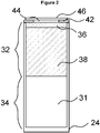
- the cartridge shown in Figure 2 comprises a housing 24 made from polypropylene, with a two-part liquid storage portion.
- the first part 32 of the liquid storage portion comprises a first capillary material 36 and a second capillary material 38.
- the second part 34 of the liquid storage portion is an empty tank that can be filled or partly filled with liquid aerosol-generating substrate.
- a ceramic substrate 42 is provided at the upper end of the cartridge.
- the substrate 24 defines an opening 44 and has electric contacts (not shown) at opposite sides thereof.
- a heater element 46 is connected to the electrical contacts of the substrate 32 and extends over the opening 44 defined by the substrate.
- Both the first capillary material 36 and the second capillary material 38 retain liquid aerosol-forming substrate.
- the first capillary material 16 which is in direct contact with the heater element 46, has a higher thermal decomposition temperature (at least 160 degree Celsius or higher such as approximately 250 degree Celsius) than the second capillary material 38.
- the first capillary material 36 effectively acts as a spacer separating the heater element 46 from the second capillary material 38 so that the second capillary material 38 is not exposed to temperatures above its thermal decomposition temperature.
- the thermal gradient across the first capillary material 36 is such that the second capillary material 38 is exposed to temperatures below its thermal decomposition temperature.
- the second capillary material 38 may be chosen to have superior wicking performance to the first capillary material 36, may retain more liquid per unit volume than the first capillary material 36 and may be less expensive than the first capillary material 36.
- the first capillary material 36 is a heat resistant material, such as a fiberglass or fiberglass containing material and the second capillary material 38 is a polymer such as high density polyethylene (HDPE), or polyethylene terephthalate (PET).
- HDPE high density polyethylene
- PET polyethylene terephthalate
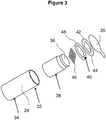
- FIG. 3 is an exploded view of a cartridge similar to the cartridge of Fig. 2 .
- the cartridge comprises a generally circular cylindrical housing 24 comprising a first part 32 and a second part 34.
- the first part of the housing 24 contains a first and a second capillary material 36, 38 that are soaked in a liquid aerosol-forming substrate.
- the aerosol-forming substrate comprises 39% by weight glycerine, 39% by weight propylene glycol, 20% by weight water and flavourings, and 2% by weight nicotine.
- a capillary material here is a material that actively conveys liquid from one end to another, and may be made from any suitable material. In this example the capillary material is formed from polyester.
- the housing 24 has an open end to which a heater assembly is fixed.
- the heater assembly comprises a substrate 42 having an aperture 44 formed in it, a pair of electrical contacts 48 fixed to the substrate 42 and separated from each other by a gap 40, and an resistive heater element 46 extending over the aperture 44 and being fixed to the electrical contacts 48 on opposing sides of the aperture 44.
- the heater assembly is covered by a removable cover 26.
- the cover 26 comprises a liquid impermeable plastic sheet that is glued to the heater assembly but which can be easily peeled off.
- a tab is provided on the side of the cover to allow a user to grasp the cover when peeling it off.
- Figure 4 shows an embodiment wherein the housing 24 has the shape of a regular cylinder with circular cross-section.
- the first and the second capillary material are made from the same material and are integrally formed as single continuous piece of capillary material 60 having the shape of a truncated cone.
- the diameter of the truncated apex of the cone corresponds to the inner diameter of the cylindrical housing.
- the diameter of the base of the cone is twice as large as the inner diameter of the cylindrical housing.
- the capillary material 60 is inserted apex first into the cylindrical housing 24 until the surface of the base of the cone lies flush with the front face of the cylindrical housing.
- the capillary material 40 Upon insertion the capillary material 40 is compressed, whereby due to the relative shape of the capillary material and the cylindrical housing, compression of the capillary material 60 is increased towards end face of the cylindrical housing. At the same time pore size or porosity of the capillary material is reduced such that the pore size or porosity of the capillary material in the vicinity of the end face of the housing is smaller than the pore size or porosity of the capillary material located in the center of the cylindrical housing.
- the open end of the cylindrical housing at the right hand side in Figure 4 is provided with a closure, such that the inside of the cylindrical housing forms a tank reservoir for holding liquid aerosol-generating substrate. At the other end the heater assembly as illustrated in Figures 2 and 3 can be provided.
- Figure 5 shows an alternative embodiment having a similar effect as the embodiment depicted in Figure 4 .
- the inner surface of the housing is provided with a conical shape, such that the interior tapers towards one end of the housing 24.
- the inner diameter of housing 24 at the left hand side in Figure 5 is half the inner diameter of housing 24 at the right hand side.
- the first and the second capillary material are made from the same material and are integrally formed as single continuous piece of capillary material 60.
- the piece of capillary material 60 has regular cylindrical form with a circular cross-section.
- the diameter cylindrical piece of capillary material 60 corresponds to the inner diameter of the housing 24 at the right hand side In Figure 5 .
- the capillary material 60 is inserted into the housing 24 until an end face of the capillary material 60 lies flush with the smaller diameter front face of the cylindrical housing, i.e with the end face at the left hand side of the housing 24. Again the capillary material 60 is compressed upon insertion, whereby due to the relative shape of the capillary material and the cylindrical housing, compression of the capillary material 60 is increased towards the left hand side end face of the cylindrical housing 24. At the same time pore size or porosity of the capillary is reduced such that the pore size or porosity of the capillary material 60 in the vicinity of the end face of the housing is smaller than the pore size or porosity of the capillary material 60 located in the center of the cylindrical housing.
- the open end of the cylindrical housing at the right hand side in Figure 5 is provided with a closure, such that the inside of the cylindrical housing forms a tank reservoir for holding liquid aerosol-generating substrate.
- the heater assembly as illustrated in Figures 2 and 3 can be provided.
- FIG. 6 a further embodiment is depicted, whereby only the capillary material 50 that is to be used with a cylindrically housing is shown.
- the first and the second capillary material again are formed from a single continuous piece of the same material 50.
- the capillary material is a rectangular piece web of capillary material having a thickness that amounts to about 25% of the inner diameter of the cylindrical housing of the cartridge.
- the width of the web of capillary material corresponds to the peripheral circumference of the housing.
- the length of the web of capillary material is about half the length of the housing of the cartridge.
- the web of capillary material is rolled up to form a cylindrical shape. In the middle of the rolled-up capillary material an air channel 52 is formed.
- a tube shaped fluid permeable heater element 54 is provided in the air channel 52 such that the heater 54 is in direct contact with the inner surface 56 of the rolled-up capillary material 50.
- the material portion 50a that is closer to the center axis of the cylinder is more compressed than the material 50b in the radial outward located portion of the capillary material.
- the capillary material is in fluid connection with a liquid reservoir (not shown), wherein the liquid reservoir is provided in the part of the housing that is not occupied by the capillary material.
- a partition is provided within the housing to ensure that the liquid substrate is not in direct communication with the air flow channel 52.
- the capillary material having a different pore size or porosity in different regions.
- a region of smaller pore size or porosity is located at one end of the capillary material.
- the region of smaller pore size or porosity is then located at the heater.
- the gradient in pore size or porosity then enhances the capillary action in the material, to draw aerosol-generating substrate liquid to the heater.
Landscapes
- Engineering & Computer Science (AREA)
- Health & Medical Sciences (AREA)
- Veterinary Medicine (AREA)
- Anesthesiology (AREA)
- Biomedical Technology (AREA)
- Heart & Thoracic Surgery (AREA)
- Hematology (AREA)
- Life Sciences & Earth Sciences (AREA)
- Animal Behavior & Ethology (AREA)
- General Health & Medical Sciences (AREA)
- Public Health (AREA)
- Textile Engineering (AREA)
- Pulmonology (AREA)
- Bioinformatics & Cheminformatics (AREA)
- Chemical & Material Sciences (AREA)
- General Chemical & Material Sciences (AREA)
- General Physics & Mathematics (AREA)
- Chemical Kinetics & Catalysis (AREA)
- Automation & Control Theory (AREA)
- Physics & Mathematics (AREA)
- Ceramic Engineering (AREA)
- Disinfection, Sterilisation Or Deodorisation Of Air (AREA)
- Catching Or Destruction (AREA)
- Containers And Packaging Bodies Having A Special Means To Remove Contents (AREA)
- Acyclic And Carbocyclic Compounds In Medicinal Compositions (AREA)
- Nozzles (AREA)
Abstract
Description
- The present invention relates aerosol-generating systems. In particular, the invention relates to handheld aerosol-generating system, such as electrically operated smoking systems. Aspects of the invention relate to a cartridge for aerosol-generating systems, in particular electrically operated smoking systems.
- One type of aerosol-generating system is an electrically operated smoking system. Handheld electrically operated smoking systems consisting of a device portion comprising a battery and control electronics, and a cartridge portion comprising a supply of aerosol-forming substrate, and an electrically operated vapouriser, are known. A cartridge comprising both a supply of aerosol-forming substrate and a vapouriser is sometimes referred to as a "cartomiser". The vapouriser typically comprises a coil of heater wire wound around an elongate wick soaked in liquid aerosol-forming substrate. Capillary material soaked in the aerosol-forming substrate supplies the liquid to the wisk. The cartridge portion typically comprises not only the supply of aerosol-forming substrate and an electrically operated vapouriser, but also a mouthpiece, which the user sucks on in use to draw aerosol into their mouth.
- In some types of electrically operated aerosol-generating devices, a reservoir of aerosol-forming liquid is provided in a tank. In use in the aerosol-generating system, the liquid is conveyed from the tank by capillary action into the wick of a coil wick heater assembly where the liquid is vaporized. When a user draws at the mouthpiece an airstream flows over the heater assembly and the generated aerosol is inhaled by the user.
- A problem of such a tank device is, that the system stops generating the aerosol if the device is held at such an angle that the liquid aerosol-generating substrate in the tank is not in contact with the capillary system. Moreover, these systems can be prone to leakage for example where the liquid from the tank floods the core or leaks through the airflow path.
- In other systems, the liquid storage portion of a cartridge is filled with a capillary medium. The liquid aerosol-generating substrate is held in the capillary material and delivered to the wick. With such system the above mentioned problems of the holding angle and the risk of leakage can be reduced. However, some residual liquid will remain in the capillary material after usage, leading to wastage. Further, there can be an inconsistency in puff deliveries in such systems due to decreasing saturation of the capillary medium during usage, which does not allow for a constant high quality smoking experience.
- It would be desirable to have a cartridge that avoids one or more of the above mentioned or other disadvantages, for example that avoids waste of aerosol-generating substrate liquid , preferably while maintaining or improving aerosol-generating performance of the aerosol-generating system, in which the cartridge is used.
- According to a first aspect of the invention there is provided a cartridge for use in an aerosol-generating system, for example an electrically operated aerosol-generating system, comprising a liquid storage portion for holding a liquid aerosol-forming substrate. The liquid storage portion comprises at least two parts in fluid communication with each other. The first part of the liquid storage portion comprises a heater assembly, a first capillary material, provided in contact with the heater assembly, and a second capillary material in contact with the first capillary material and spaced apart from the heater assembly by the first capillary material. The second part of the liquid storage portion comprises a container for holding aerosol-forming substrate in liquid form and preferably arranged for supplying the liquid to the second capillary material. The second part of the liquid storage portion may comprise a tank that is substantially empty and is suitable for holding aerosol-forming substrate in liquid form.
- The capillary material is preferably designed such that it is capable of holding sufficient liquid substrate for several puffs. As the capillary material is located in contact with the heater, the heater is provided independent of the holding angle of the aerosol-generating liquid with sufficient aerosol-generating liquid. The remaining inner volume of the liquid storage portion comprises no capillary material but represents an empty tank for storing aerosol-generating liquid. Under normal handling conditions an aerosol-generating medium, in particular an aerosol-generating smoking device, is transported between puffs and the capillary material will regularly contact and re-absorb new aerosol-generating liquid.
- Because of the reduced amount of the capillary material used, the amount of residual liquid remaining in the capillary material after usage of the cartridge is smaller than in conventional cartridges in which the whole liquid storage portion is filled with capillary material. Moreover, performance tests have shown that the TPM (total particulate matter) yield of aerosol-generating smoking devices equipped with cartridges of the present invention is in many examples at least comparable to the performance of aerosol-generating smoking devices equipped with currently available cartridges.
- Preferably the liquid capacity of the capillary material is such that it can hold enough liquid for 30 to 40 puffs or more. A 3 second puff may include about 1 mg to 4mg of liquid, for example 3mg to 4mg of liquid. Preferably the capacity of the capillary material is between about 30mg to about 160mg, preferably 90 mg to about 160 mg or more, preferably 100 mg to 150 mg, for example 130 mg. Where there are two layers making up the capillary material, the capacity of the first and second layers may be such that about 10 to 20 % by weight of the liquid capacity is in the first layer. For example, where the capacity of the capillary material is 30 puffs, the capacity of the first layer may be about 5 puffs, and the capacity of the second layer may be about 25 puffs.
- Without wishing to be bound by any particular theory, it is thought that by the capillary material having capacity for several puffs, for example 30 or more puffs, the risk of leakage from the device is reduced. It is thought that if the capillary material is too small, then on puffing, liquid may be drawn from the reservoir straight through the capillary material and heater without being vapourised, leading to leakage. Also by having a capacity of 90 mg and more, a number of puffs can be taken from the device, even when the liquid in the reservoir is not in direct contact with the capillary material.
- The heater assembly may be substantially flat and may comprise electrically conductive filaments, without the need for any winding of a heater wire around a capillary wick.
- The electrically conductive filaments may lie in a single plane. A planar heater assembly can be easily handled during manufacture and provides for a robust construction.
- The electrically conductive filaments may define interstices between the filaments and the interstices may have a width of between 10 µm and 100 µm. The filaments may give rise to capillary action in the interstices, so that in use, liquid to be vapourised is drawn into the interstices, increasing the contact area between the heater assembly and the liquid.
- The electrically conductive filaments may form a mesh of size between 160 and 600 Mesh US (+/- 10%) (i.e. between 160 and 600 filaments per inch (+/- 10%)). The width of the interstices is preferably between 75 µm and 25 µm. The percentage of open area of the mesh, which is the ration of the area of the interstices to the total area of the mesh is preferably between 25 and 56%. The mesh may be formed using different types of weave or lattice structures. Alternatively, the electrically conductive filaments consist of an array of filaments arranged parallel to one another.
- The electrically conductive filaments may have a diameter of between 10 µm and 100 µm, preferably between 8 µm and 50 µm, and more preferably between 8 µm and 39 µm. The filaments may have a round cross section or may have a flattened cross-section. The heater filaments may be formed by etching a sheet material, such as a foil. This may be particularly advantageous when the heater assembly comprises an array of parallel filaments. If the heater assembly comprises a mesh or fabric of filaments, the filaments may be individually formed and knitted together.
- As described in relation to the first aspect, the heater assembly may comprise at least one filament made from a first material and at least one filament made from a second material different from the first material.
- The heater assembly may comprise an electrically insulating substrate on which the filaments are supported, the filaments extending across an aperture formed in the substrate. The electrically insulating substrate may comprise any suitable material, and is preferably a material that is able to tolerate high temperatures (in excess of 300 degree Celsius) and rapid temperature changes. An example of a suitable material is a polyimide film, such as Kapton®.
- The heater assembly may comprise an electrically conductive contact in contact with a plurality of the filaments. The electrically conductive contact may be provided between the housing of the liquid storage portion and the electrically insulating substrate. The electrically conductive contact may be provided between the filaments and the electrically insulating substrate. An aperture may be formed in the electrically insulating layer, and the cartridge may comprise two electrically conductive contacts positioned on opposite sides on the aperture to one another.
- A capillary material is preferably a material that actively conveys liquid from one end of the material to another. The capillary material is advantageously oriented in the housing to convey liquid to the heater assembly.
- The second capillary material may comprise a fibrous structure wherein the fibres are generally oriented in the direction of movement in the liquid to the heater. The first capillary material may have less oriented fibres. For example the first capillary material may have the structure of a felt.
- The capillary material may have a fibrous or spongy structure. The capillary material preferably comprises a bundle of capillaries. For example, the capillary material may comprise a plurality of fibres or threads or other fine bore tubes. The fibres or threads may be generally aligned to convey liquid to the heater. Alternatively, the capillary material may comprise sponge-like or foam-like material. The structure of the capillary material forms a plurality of small bores or tubes, through which the liquid can be transported by capillary action. The capillary material may comprise any suitable material or combination of materials. Examples of suitable materials are a sponge or foam material, ceramic- or graphite-based materials in the form of fibres or sintered powders, foamed metal or plastics material, a fibrous material, for example made of spun or extruded fibres, such as cellulose acetate, polyester, or bonded polyolefin, polyethylene, terylene or polypropylene fibres, nylon fibres or ceramic. The capillary material may have any suitable capillarity and porosity so as to be used with different liquid physical properties. The liquid has physical properties, including but not limited to viscosity, surface tension, density, thermal conductivity, boiling point and vapour pressure, which allow the liquid to be transported through the capillary device by capillary action.
- The capillary material may be in contact with the heater, for example with the electrically conductive filaments. The capillary material may extend into interstices between the filaments. The heater assembly may draw liquid aerosol-forming substrate into the interstices by capillary action. The capillary material may be in contact with the electrically conductive filaments over substantially the entire extent of the aperture.
- The housing may contain two or more different capillary materials, wherein a first capillary material, in contact with the heater element, has a higher thermal decomposition temperature and a second capillary material, in contact with the first capillary material but not in contact with the heater element has a lower thermal decomposition temperature. The first capillary material effectively acts as a spacer separating the heater element from the second capillary material so that the second capillary material is not exposed to temperatures above its thermal decomposition temperature. As used herein, "thermal decomposition temperature" means the temperature at which a material begins to decompose and lose mass by generation of gaseous by products. The second capillary material may advantageously occupy a greater volume than the first capillary material and may hold more aerosol-forming substrate that the first capillary material. The second capillary material may have superior wicking performance to the first capillary material. The second capillary material may be cheaper than the first capillary material. The second capillary material may be polypropylene.
- The first capillary material can be selected from the group of kevlar felt, ceramic paper, ceramic felt, carbon felt, cellulose acetate, hemp felt, PET/PBT sheet, cotton pad, porous ceramic disc or porous metal disc.
- Preferred materials include Kevlar felt, ceramic paper, ceramic felt, porous ceramic disc or porous metal disc. The first capillary material may comprise glass fibre paper or felt. Preferably the first capillary material includes substantially no organic matter.
- Preferably the porosity of the first capillary material is less than that of the second capillary material. Preferably the pore size of the first capillary material is less than that of the second capillary material. The pore size may be for example measured as being an average pore size for a region of the capillary material. In this way it can be seen that the aerosol-generating substrate moves more efficiently to the heater. In a broad aspect of the invention, a cartridge is provided which includes a heater and a capillary material in contact with the heater for supplying aerosol-generating substrate to the heater, wherein the porosity or pore size of a region of the capillary material adjacent the heater is less than the porosity or pore size of a region of the capillary material remote from the heater. Thus a single material may be used, for example which has a gradient of pore size in one or more of its dimensions.
- The first capillary material may have a fiber size/pore size of between 0,1 to 50 µm, preferably of between 0,5 to 10 µm and most preferably of about 4 µm. The first capillary material has a density of below 2 g/ml, and preferably of about 0.5 g/ml.
- The second capillary material can be a so-called high retention material (HRM) material, selected from the group of polypropylene (PP), polyethylene (PE), polyphenylene sulphide (PPS), polyethylene terephthalate (PET), polybutylene terephthalate (PBT), rolled non-woven material or rolled felts. Preferably the second capillary material comprises a polymeric material. The material may include a coating, for example to reduce hydrophobicity.
- The second capillary material may have a fiber size/pore size of between 1 to 100 µm, preferably of between 15 to 40 µm and most preferably of about 25 µm. The second capillary material may have a density of below 1 g/ml, and preferably of between 0.1 and 0.3 g/ml.
- The first capillary material may separate the heater assembly from the second capillary material by a distance of at least 0.8 mm, for example at least 1.5 mm, and preferably between 0.8mm and 2 mm in order to provide a sufficient temperature drop across the first capillary material.
- The first and second capillary material can also be made from the same material, and can only be distinguished from each other in that they exhibit different porosities or different capillarity. For example the first capillary material can be compressed such that its pore size or porotisy is reduced and its capillarity is increased compared to the second capillary material which may be used in an uncompressed or at least in a less compressed state.
- In a preferred embodiment the first and the second material are made from a single continuous element of the same base material. More preferably the material is treated such that a gradient of pore size or porosity is obtained in a direction towards the heater element or the opening, such that the pore size or porosity decreases, for example continuously decreases, within the capillary material towards the heater element.
- Preferably at least the first capillary material is compressed upon insertion into the first part of the housing of the liquid storage portion such that its effective pore size or porosity is reduced. For example the single continuous element may have the shape of a truncated cone, wherein the diameter of the circular base of the truncated cone is larger than the inner diameter of the cylindrical housing of the liquid storage portion, while the diameter of the truncated apex of the cone substantially corresponds to the inner diameter of the cylindrical housing of the liquid storage portion. Upon insertion the capillary material at the base of the cone of capillary material is more compressed than at the area of the truncated apex. The more compressed material represents the first capillary material and the less compressed material represents the second capillary material. The skilled artisan will readily appreciate that the resulting gradient of compression depends on the relative shape chosen for the capillary element and the housing of the liquid storage portion.
- In a particularly preferred embodiment, the capillary element has a regular cylindrical shape with circular cross-section and a predefined diameter. The inner surface of the housing comprises a tapered portion at the opening end, such that the capillary material is compressed by this tapered portion upon insertion of the capillary material into the housing. Preferably the inner surface of the housing has a conical shape such that the inner diameter continuously increases from the open end towards the closed end of the cartridge.
- The first capillary material and the second capillary material may comprise different regions of the same capillary material element. Compression of the capillary material when laced in the housing may be such that the pore size or porosity of the capillary material reduced or continuously reduces towards the heater assembly.
- In a further embodiment the first and the second capillary material again are formed from a single continuous piece of the same material. The capillary material may be rectangular web of capillary material having a thickness that amounts to below 50%, preferably to about 25 % of the inner diameter of the cylindrical housing of the cartridge. The width of the web of capillary material corresponds to the peripheral circumference of the housing. The web of capillary material can have any desired length and preferably is about half the length of the housing of the cartridge. The web of capillary material is rolled up to form a cylindrical shape. By rolling up, the central portion of the web is compressed to a higher degree than the outer portions of the web such that a gradient of pore size or porosity is obtained in radial direction of the rolled-up web of capillary material. In the middle the rolled-up capillary material an air channel is formed. A tube shaped fluid permeable heater element is provided in the air channel such that the heater is in direct contact with the inner surface of the rolled-up capillary material. Upon rolling up the capillary material the material portion that is closer to the center axis of the cylinder is more compressed than the material in the radial outward located portion of the capillary material. Thus, again a gradient of pore size is obtained, wherein the pore size of the capillary material is continuously decreased within the capillary material in the direction to the heater element. The capillary material is in fluid connection with a liquid reservoir, wherein the liquid reservoir is provided in the part of the housing that is not occupied by the capillary material. A partition is provided within the housing to ensure that the liquid substrate is not in direct communication with the air flow channel.
- The web of capillary material may also comprise a plurality of layers of capillary material, such that the liquid retention properties of the capillary material can be designed in any desired way that is most suitable for the given aerosol-generating system.
- In a particular preferred embodiment the heater element is rolled-up together with the capillary material, such that in only one manufacturing step a combined capillary material with radial gradient and included heating element is obtained.
- The liquid storage portion may be positioned on a first side of the electrically conductive filaments and an airflow channel positioned on an opposite side of the electrically conductive filaments to the liquid storage portion, such that air flow past the electrically conductive filaments entrains vapourised liquid aerosol-forming substrate.
- Preferably, the aerosol generating system comprises a housing. Preferably, the housing is elongate. The housing may comprise any suitable material or combination of materials. Examples of suitable materials include metals, alloys, plastics or composite materials containing one or more of those materials, or thermoplastics that are suitable for food or pharmaceutical applications, for example polypropylene, polyetheretherketone (PEEK) and polyethylene. Preferably, the material is light and non-brittle. The material may include PET, PBT or PPS.
- Preferably, the aerosol-generating system is portable. The aerosol-generating system may have a size comparable to a conventional cigar or cigarette. The smoking system may have a total length between approximately 30 mm and approximately 150 mm. The smoking system may have an external diameter between approximately 5 mm and approximately 30mm.
- The aerosol-forming substrate is a substrate capable of releasing volatile compounds that can form an aerosol. The volatile compounds may be released by heating the aerosol-forming substrate.
- The aerosol-forming substrate may comprise plant-based material. The aerosol-forming substrate may comprise tobacco. The aerosol-forming substrate may comprise a tobacco-containing material containing volatile tobacco flavour compounds, which are released from the aerosol-forming substrate upon heating. The aerosol-forming substrate may alternatively comprise a non-tobacco-containing material. The aerosol-forming substrate may comprise homogenised plant-based material. The aerosol-forming substrate may comprise homogenised tobacco material. The aerosol-forming substrate may comprise at least one aerosol-former. The aerosol-forming substrate may comprise other additives and ingredients, such as flavourants.
- Preferably the liquid storage portion comprises an opening and the heater assembly extends across the opening of the housing. The heater assembly may comprise an electrically insulating substrate on which the heater element is supported. The electrically insulating substrate may comprise any suitable material, and is preferably a material that is able to tolerate high temperatures (in excess of 300 degree Celsius) and rapid temperature changes. An example of a suitable material is a polyimide film, such as Kapton®. The electrically insulating substrate may have an aperture formed in it, with the heater element extending across the aperture. The heater assembly may comprise electrical contacts connected to the electrically conductive filaments.
- According to a second aspect of the invention there is provided a cartridge for use in an aerosol-generating system, for example an electrically operated aerosol-generating system, with a liquid storage portion comprising a housing for holding a liquid aerosol-forming substrate, wherein the liquid storage portion comprises at least two parts in fluid communication to each other. The first part of the liquid storage portion comprises a first capillary material, provided at the vicinity of the opening of the housing, and a second capillary material in contact with the first capillary material and spaced apart from the opening by the first capillary material. The second part of the liquid storage portion may be substantially empty and being suitable for holding aerosol-forming substrate in liquid form.
- The cartridge preferably further comprises a fluid permeable heater assembly extending across the opening of the housing.
- In the embodiments of the present invention wherein the first part of the liquid storage portion occupies below 50 %, preferably between 10 % and 30 %, more preferably between 15 % and 25 % and most preferably about 20 % of the volume of the liquid storage portion.
- The capillary material extends across the complete cross-section of the first part of the liquid storage portion, such that it is not possible for the liquid aerosol-generating substrate to flow directly to the heater assembly or the opening of the cartridge.
- According to a further aspect of the invention there is provided an aerosol-generating system comprising a cartridge according to the present invention.
- The system may further comprise electric circuitry connected to the heater assembly and to an electrical power source, the electric circuitry configured to monitor the electrical resistance of the heater assembly or of one or more filaments of the heater assembly, and to control the supply of power to the heater assembly dependent on the electrical resistance of the heater assembly or the one or more filaments.
- The electric circuitry may comprise a microprocessor, which may be a programmable microprocessor. The electric circuitry may comprise further electronic components. The electric circuitry may be configured to regulate a supply of power to the heater assembly. Power may be supplied to the heater assembly continuously following activation of the system or may be supplied intermittently, such as on a puff-by-puff basis. The power may be supplied to the heater assembly in the form of pulses of electrical current.
- The system advantageously comprises a power supply, typically a battery, within the main body of the housing. As an alternative, the power supply may be another form of charge storage device such as a capacitor. The power supply may require recharging and may have a capacity that allows for the storage of enough energy for one or more smoking experiences; for example, the power supply may have sufficient capacity to allow for the continuous generation of aerosol for a period of around six minutes, corresponding to the typical time taken to smoke a conventional cigarette, or for a period that is a multiple of six minutes. In another example, the power supply may have sufficient capacity to allow for a predetermined number of puffs or discrete activations of the heater assembly.
- Preferably, the aerosol generating system comprises a housing. Preferably, the housing is elongate. The housing may comprise any suitable material or combination of materials. Examples of suitable materials include metals, alloys, plastics or composite materials containing one or more of those materials, or thermoplastics that are suitable for food or pharmaceutical applications, for example polypropylene, polyetheretherketone (PEEK) and polyethylene. Preferably, the material is light and non-brittle.
- Preferably, the aerosol-generating system is portable. The aerosol-generating system may have a size comparable to a conventional cigar or cigarette. The smoking system may have a total length between approximately 30 mm and approximately 150 mm. The smoking system may have an external diameter between approximately 5 mm and approximately 30mm.
- The aerosol-forming substrate is a substrate capable of releasing volatile compounds that can form an aerosol. The volatile compounds may be released by heating the aerosol-forming substrate.
- The aerosol-forming substrate may comprise plant-based material. The aerosol-forming substrate may comprise tobacco. The aerosol-forming substrate may comprise a tobacco-containing material containing volatile tobacco flavour compounds, which are released from the aerosol-forming substrate upon heating. The aerosol-forming substrate may alternatively comprise a non-tobacco-containing material. The aerosol-forming substrate may comprise homogenised plant-based material. The aerosol-forming substrate may comprise homogenised tobacco material. The aerosol-forming substrate may comprise at least one aerosol-former. The aerosol-forming substrate may comprise other additives and ingredients, such as flavourants.
- Preferably the system comprises a mouthpiece, wherein the cartridge is inserted into the system in an orientation that the opening of the cartridge points away from the mouthpiece.
- In another preferred embodiment the cartridge is inserted into the system in an orientation that the opening of the cartridge points towards the mouthpiece. Depending on the circumstances of usage one of these orientations of the cartridge may provide for superior performance compared to the other.
- According to a further aspect of the invention there is provided a cartridge for use in an aerosol-generating system, comprising: a liquid storage portion comprising a housing for holding a liquid aerosol-forming substrate, the liquid storage portion comprising a heater assembly, and a capillary material, provided in contact with the heater assembly, wherein the average porosity or pore size of a region of the capillary material adjacent the heater assembly is smaller than the average porosity or pore size of a region of the capillary material remote from the heater assembly. A portion of the capillary material in the region may be compressed to reduce its porosity or pore size. The liquid storage portion may comprise at least two parts in fluid communication with each other, the first part of the liquid storage portion comprising the capillary material, and the second part of the liquid storage portion comprising a container for holding aerosol-forming substrate in liquid form and supplying the liquid to the higher porosity or pore size region of the capillary material.
- The present invention is also directed to a method for manufacturing a cartridge for use in an electrically operated aerosol-generating system, comprising the steps of providing a liquid storage portion comprising a housing with a first part and a second part, providing heater assembly, placing a first capillary material in the first part of the housing of the liquid storage portion, such that first capillary material is provided in direct contact with the heater assembly, placing a second capillary material in the first part of the housing of the liquid storage portion, such that the second capillary material is in contact with the first capillary material and is spaced apart from the heater assembly by the first capillary material. The second part of the liquid storage portion is substantially empty and is suitable for holding aerosol-forming substrate in liquid form.
- Preferably the first capillary material is compressed during or before insertion into the housing such that its pore size or porosity is reduced compared to the pore size or porosity in the relaxed state.
- An aspect of the invention further provides a method of manufacture of a cartridge for use in an aerosol-generating system, comprising: providing a liquid storage portion comprising a housing, providing a heater assembly, placing a capillary material in the housing of the liquid storage portion, such that the capillary material is provided in direct contact with the heater assembly, wherein the method includes the step of compressing a portion of the capillary material during or before placing in the housing such that the porosity or pore size of the portion of the capillary material is reduced.
- The invention also provides an aerosol-generating system as described herein being an electrically operated smoking system.
- The term "substantially flat" filament arrangement preferably refers to a filament arrangement that is in the form of a substantially two dimensional topological manifold. Thus, the substantially flat filament arrangement extends in two dimensions along a surface substantially more than in a third dimension. In particular, the dimensions of the substantially flat filament arrangement in the two dimensions within the surface is at least 5 times larger than in the third dimension, normal to the surface. An example of a substantially flat filament arrangement is a structure between two substantially parallel surfaces, wherein the distance between these two surfaces is substantially smaller than the extension within the surfaces. In some embodiments, the substantially flat filament arrangement is planar. In other embodiments, the substantially flat filament arrangement is curved along one or more dimensions, for example forming a dome shape or bridge shape.
- The term "filament" preferably refers to an electrical path arranged between two electrical contacts. A filament may arbitrarily branch off and diverge into several paths or filaments, respectively, or may converge from several electrical paths into one path. A filament may have a round, square, flat or any other form of cross-section. A filament may be arranged in a straight or curved manner.
- The term "filament arrangement" preferably refers to an arrangement of one or preferably a plurality of filaments. The filament arrangement may be an array of filaments, for example arranged parallel to each other. Preferably, the filaments may form a mesh. The mesh may be woven or non-woven.
- It will be understood that, where appropriate, features of one aspect of the invention may be provided in relation to another aspect of the invention, in any appropriate combination.
- The invention will be further described, by way of example only, with reference to the accompanying drawings in which:
-
Figures 1a to 1d are schematic illustrations of a system, incorporating a cartridge, in accordance with an embodiment of the invention -
Figure 2 shows a cartridge with porous medium according to a first aspect of the present invention; -
Figure 3 shows an exploded view of a similar cartridge as shown inFig. 2 ; -
Figure 4 shows a cartridge with a single porous medium compressed by the shape of porous material upon insertion into the housing; -
Figure 5 shows a cartridge with a single porous medium compressed by the shape of inner surface of the housing upon insertion into the housing; -
Figure 6 shows a capillary material rolled-up into a cylindrical shape and being provided with a tube-shaped heater in the centre. -
Figures 1a to 1d are schematic illustrations of an aerosol-generating system, including a cartridge in accordance with an embodiment of the invention.Figure 1a is a schematic view of an aerosol-generatingdevice 10 and aseparate cartridge 20, which together form the aerosol-generating system. In this example, the aerosol-generating system is an electrically operated smoking system. - The
cartridge 20 contains an aerosol-forming substrate and is configured to be received in acavity 18 within the device.Cartridge 20 should be replaceable by a user when the aerosol-forming substrate provided in the cartridge is depleted.Figure 1a shows thecartridge 20 just prior to insertion into the device, with the arrow 1 inFigure 1a indicating the direction of insertion of the cartridge. - The aerosol-generating
device 10 is portable and has a size comparable to a conventional cigar or cigarette. Thedevice 10 comprises amain body 11 and amouthpiece portion 12. Themain body 11 contains abattery 14, such as a lithium iron phosphate battery,control electronics 16 and acavity 18. Themouthpiece portion 12 is connected to themain body 11 by a hingedconnection 21 and can move between an open position as shown inFigure 1a to 1c and a closed position as shown inFigure 1d . Themouthpiece portion 12 is placed in the open position to allow for insertion and removal ofcartridges 20 and is placed in the closed position when the system is to be used to generate aerosol, as will be described. The mouthpiece portion comprises a plurality ofair inlets 13 and anoutlet 15. In use, a user sucks or puffs on the outlet to draw air from theair inlets 13, through the mouthpiece portion to theoutlet 15, and thereafter into the mouth or lungs of the user. Internal baffles 17 are provided to force the air flowing through themouthpiece portion 12 past the cartridge, as will be described. - The
cavity 18 has a circular cross-section and is sized to receive ahousing 24 of thecartridge 20.Electrical connectors 19 are provided at the sides of thecavity 18 to provide an electrical connection between thecontrol electronics 16 andbattery 14 and corresponding electrical contacts on thecartridge 20. -
Figure 1b shows the system ofFigure 1a with the cartridge inserted into the cavity 118, and thecover 26 being removed. In this position, the electrical connectors rest against the electrical contacts on the cartridge, as will be described. -
Figure 1c shows the system ofFigure 1b with thecover 26 fully removed and themouthpiece portion 12 being moved to a closed position. -
Figure 1d shows the system ofFigure 1c with themouthpiece portion 12 in the closed position. Themouthpiece portion 12 is retained in the closed position by a clasp mechanism, Themouthpiece portion 12 in a closed position retains the cartridge in electrical contact with theelectrical connectors 19 so that a good electrical connection is maintained in use, whatever the orientation of the system is. Themouthpiece portion 12 may include an annular elastomeric element that engages a surface of the cartridge and is compressed between a rigid mouthpiece housing element and the cartridge when themouthpiece portion 12 is in the closed position. This ensures that a good electrical connection is maintained despite manufacturing tolerances. - Of course other mechanisms for maintaining a good electrical connection between the cartridge and the device may, alternatively or in addition, be employed. For example, the
housing 24 of thecartridge 20 may be provided with a thread or groove (not illustrated) that engages a corresponding groove or thread (not illustrated) formed in the wall of thecavity 18. A threaded engagement between the cartridge and device can be used to ensure the correct rotational alignment as well as retaining the cartridge in the cavity and ensuring a good electrical connection. The threaded connection may extend for only half a turn or less of the cartridge, or may extend for several turns. Alternatively, or in addition, theelectrical connectors 19 may be biased into contact with the contacts on the cartridge. - Other cartridge designs incorporating a capillary material arrangement in accordance with this disclosure can now be conceived by one of ordinary skill in the art. For example, the cartridge may include a mouthpiece portion, may include more than one heater assembly and may have any desired shape. Furthermore, a capillary assembly in accordance with the disclosure may be used in systems of other types to those already described, such as humidifiers, air fresheners, and other aerosol-generating systems
- The exemplary embodiments described above illustrate but are not limiting. In view of the above discussed exemplary embodiments, other embodiments consistent with the above exemplary embodiments will now be apparent to one of ordinary skill in the art.
- The cartridge shown in
Figure 2 comprises ahousing 24 made from polypropylene, with a two-part liquid storage portion. Thefirst part 32 of the liquid storage portion comprises a firstcapillary material 36 and a secondcapillary material 38. Thesecond part 34 of the liquid storage portion is an empty tank that can be filled or partly filled with liquid aerosol-generating substrate. - At the upper end of the cartridge a
ceramic substrate 42 is provided. Thesubstrate 24 defines anopening 44 and has electric contacts (not shown) at opposite sides thereof. Aheater element 46 is connected to the electrical contacts of thesubstrate 32 and extends over theopening 44 defined by the substrate. - Both the first
capillary material 36 and the secondcapillary material 38 retain liquid aerosol-forming substrate. The firstcapillary material 16, which is in direct contact with theheater element 46, has a higher thermal decomposition temperature (at least 160 degree Celsius or higher such as approximately 250 degree Celsius) than the secondcapillary material 38. The firstcapillary material 36 effectively acts as a spacer separating theheater element 46 from the secondcapillary material 38 so that the secondcapillary material 38 is not exposed to temperatures above its thermal decomposition temperature. The thermal gradient across the firstcapillary material 36 is such that the secondcapillary material 38 is exposed to temperatures below its thermal decomposition temperature. The secondcapillary material 38 may be chosen to have superior wicking performance to the firstcapillary material 36, may retain more liquid per unit volume than the firstcapillary material 36 and may be less expensive than the firstcapillary material 36. In this example the firstcapillary material 36 is a heat resistant material, such as a fiberglass or fiberglass containing material and the secondcapillary material 38 is a polymer such as high density polyethylene (HDPE), or polyethylene terephthalate (PET). -
Figure 3 is an exploded view of a cartridge similar to the cartridge ofFig. 2 . The cartridge comprises a generally circularcylindrical housing 24 comprising afirst part 32 and asecond part 34. The first part of thehousing 24 contains a first and a secondcapillary material - The
housing 24 has an open end to which a heater assembly is fixed. The heater assembly comprises asubstrate 42 having anaperture 44 formed in it, a pair ofelectrical contacts 48 fixed to thesubstrate 42 and separated from each other by agap 40, and anresistive heater element 46 extending over theaperture 44 and being fixed to theelectrical contacts 48 on opposing sides of theaperture 44. - The heater assembly is covered by a
removable cover 26. Thecover 26 comprises a liquid impermeable plastic sheet that is glued to the heater assembly but which can be easily peeled off. A tab is provided on the side of the cover to allow a user to grasp the cover when peeling it off. It will now be apparent to one of ordinary skill in the art that although gluing is described as the method to a secure the impermeable plastic sheet to the heater assembly, other methods familiar to those in the art may also be used including heat sealing or ultrasonic welding, so long as the cover may easily be removed by a consumer. -
Figure 4 shows an embodiment wherein thehousing 24 has the shape of a regular cylinder with circular cross-section. The first and the second capillary material are made from the same material and are integrally formed as single continuous piece ofcapillary material 60 having the shape of a truncated cone. The diameter of the truncated apex of the cone corresponds to the inner diameter of the cylindrical housing. The diameter of the base of the cone is twice as large as the inner diameter of the cylindrical housing. Thecapillary material 60 is inserted apex first into thecylindrical housing 24 until the surface of the base of the cone lies flush with the front face of the cylindrical housing. Upon insertion thecapillary material 40 is compressed, whereby due to the relative shape of the capillary material and the cylindrical housing, compression of thecapillary material 60 is increased towards end face of the cylindrical housing. At the same time pore size or porosity of the capillary material is reduced such that the pore size or porosity of the capillary material in the vicinity of the end face of the housing is smaller than the pore size or porosity of the capillary material located in the center of the cylindrical housing. The open end of the cylindrical housing at the right hand side inFigure 4 is provided with a closure, such that the inside of the cylindrical housing forms a tank reservoir for holding liquid aerosol-generating substrate. At the other end the heater assembly as illustrated inFigures 2 and3 can be provided. -
Figure 5 shows an alternative embodiment having a similar effect as the embodiment depicted inFigure 4 . In this case the inner surface of the housing is provided with a conical shape, such that the interior tapers towards one end of thehousing 24. Here the inner diameter ofhousing 24 at the left hand side inFigure 5 is half the inner diameter ofhousing 24 at the right hand side. Again the first and the second capillary material are made from the same material and are integrally formed as single continuous piece ofcapillary material 60. The piece ofcapillary material 60 has regular cylindrical form with a circular cross-section. The diameter cylindrical piece ofcapillary material 60 corresponds to the inner diameter of thehousing 24 at the right hand side InFigure 5 . Thecapillary material 60 is inserted into thehousing 24 until an end face of thecapillary material 60 lies flush with the smaller diameter front face of the cylindrical housing, i.e with the end face at the left hand side of thehousing 24. Again thecapillary material 60 is compressed upon insertion, whereby due to the relative shape of the capillary material and the cylindrical housing, compression of thecapillary material 60 is increased towards the left hand side end face of thecylindrical housing 24. At the same time pore size or porosity of the capillary is reduced such that the pore size or porosity of thecapillary material 60 in the vicinity of the end face of the housing is smaller than the pore size or porosity of thecapillary material 60 located in the center of the cylindrical housing. Again, the open end of the cylindrical housing at the right hand side inFigure 5 is provided with a closure, such that the inside of the cylindrical housing forms a tank reservoir for holding liquid aerosol-generating substrate. At the other end face of the housing, the heater assembly as illustrated inFigures 2 and3 can be provided. - In
Figure 6 a further embodiment is depicted, whereby only thecapillary material 50 that is to be used with a cylindrically housing is shown. The first and the second capillary material again are formed from a single continuous piece of thesame material 50. The capillary material is a rectangular piece web of capillary material having a thickness that amounts to about 25% of the inner diameter of the cylindrical housing of the cartridge. The width of the web of capillary material corresponds to the peripheral circumference of the housing. The length of the web of capillary material is about half the length of the housing of the cartridge. The web of capillary material is rolled up to form a cylindrical shape. In the middle of the rolled-up capillary material anair channel 52 is formed. A tube shaped fluidpermeable heater element 54 is provided in theair channel 52 such that theheater 54 is in direct contact with theinner surface 56 of the rolled-upcapillary material 50. Upon rolling up the capillary material thematerial portion 50a that is closer to the center axis of the cylinder is more compressed than the material 50b in the radial outward located portion of the capillary material. Thus, again a gradient of pore size or porosity is obtained, wherein the pore size or porosity of thecapillary material 50 is continuously decreased within the capillary material in the direction towards theheater element 54. The capillary material is in fluid connection with a liquid reservoir (not shown), wherein the liquid reservoir is provided in the part of the housing that is not occupied by the capillary material. A partition is provided within the housing to ensure that the liquid substrate is not in direct communication with theair flow channel 52. - It will be understood that different methods and configurations are possible to obtain the capillary material having a different pore size or porosity in different regions. In each example, a region of smaller pore size or porosity is located at one end of the capillary material. The region of smaller pore size or porosity is then located at the heater. The gradient in pore size or porosity then enhances the capillary action in the material, to draw aerosol-generating substrate liquid to the heater.
Claims (24)
- A cartridge for use in an aerosol-generating system, comprising:a liquid storage portion comprisinga housing for holding a liquid aerosol-forming substrate, wherein the liquid storage portion comprises at least two parts in fluid communication with each other, the first part of the liquid storage portion comprising- a heater assembly,- a first capillary material, provided in contact with the heater assembly,- a second capillary material in contact with the first capillary material and spaced apart from the heater assembly by the first capillary material,the second part of the liquid storage portion comprising a container for holding aerosol-forming substrate in liquid form and supplying the liquid to the second capillary material.
- A cartridge according to claim 1, wherein the liquid storage portion comprises an opening and the heater assembly extends across the opening of the housing.
- A cartridge for use in an aerosol-generating system, comprising:a liquid storage portion comprisinga housing for holding a liquid aerosol-forming substrate, the housing having an opening,wherein the liquid storage portion comprises at least two parts in fluid communication to each other, the first part of the liquid storage portion comprising- a first capillary material, provided in the vicinity of the opening of the housing,- a second capillary material in fluid contact with the first capillary material and spaced apart from the opening by the first capillary material,the second part of the liquid storage portion comprising a container for holding aerosol-forming substrate in liquid form and supplying the liquid to the second capillary material.
- A cartridge according to claim 3, further comprising a fluid permeable heater assembly extending across the opening of the housing.
- A cartridge according to one of the preceding claims, wherein the average pore size or porosity of the first capillary material is less than the average pore size or porosity of the second capillary material.
- A cartridge according to any one of the preceding claims, wherein the first capillary material has a fiber size or pore size of between 0,1 to 50 µm, preferably of between 0,5 to 10 µm and most preferably of about 4 µm.
- A cartridge according to any one of the preceding claims, wherein the first capillary material has a density of below 2 g/ml, and preferably of about 0.5 g/ml.
- A cartridge according to any one of the preceding claims, wherein the second capillary material has a fiber size or pore size of between 1 to 100 µm, preferably of between 15 to 40 µm and most preferably of about 25 µm.
- A cartridge according to claim 7 or 8, wherein the second capillary material has a density of below 1 g/ml, and preferably of between 0.1 and 0.3 g/ml.
- A cartridge according to one of the previous claims, wherein the first capillary material or the second capillary is compressed in the housing such that its effective pore size is reduced.
- A cartridge according to any one of the preceding claims wherein the first capillary material and the second capillary material comprise different regions of the same capillary material element.
- A cartridge according to one of the previous claims, wherein the compression of the capillary material when placed in the housing is such that the pore size or porosity of the capillary material continuously reduces towards the heater assembly.
- A cartridge according to one of the previous claims, wherein the first and the second capillary material are formed as an integral element from a continuous piece of material, whereby the cross-section at one end of the element is increased.
- A cartridge according to one of the previous claims, wherein the inner surface of the housing is shaped in form of a regular cylinder with circular cross-section and the piece of capillary material is cone-shaped.
- A cartridge according to one of the previous claims, wherein the capillary material has regular cylindrical shape with circular cross section, and wherein the inner surface of the housing comprises a tapered portion at the opening end, such that the capillary material is compressed by this tapered portion upon insertion of the capillary material into the housing.
- A cartridge for use in an aerosol-generating system, comprising:a liquid storage portion comprisinga housing for holding a liquid aerosol-forming substrate, the liquid storage portion comprising- a heater assembly,- a capillary material, provided in contact with the heater assembly,wherein the average porosity or pore size of a region of the capillary material adjacent the heater assembly is smaller than the average porosity or pore size of a region of the capillary material remote from the heater assembly.
- A cartridge according to claim 16, wherein a portion of the capillary material in the region is compressed to reduce its porosity or pore size.
- A cartridge according to claim 16 or claim 17, wherein the liquid storage portion comprises at least two parts in fluid communication with each otherthe first part of the liquid storage portion comprising the capillary material, andthe second part of the liquid storage portion comprising a container for holding aerosol-forming substrate in liquid form and supplying the liquid to the higher porosity or pore size region of the capillary material.
- A method of manufacture of a cartridge for use in an aerosol-generating system, comprising:- providing a liquid storage portion comprising a housing with a first part and a second part,- providing a heater assembly,- placing a first capillary material in the first part of the housing of the liquid storage portion, such that first capillary material is provided in direct contact with the heater assembly,- placing a second capillary material in the first part of the housing of the liquid storage portion, such that the second capillary material is in contact with the first capillary material and is spaced apart from the heater assembly by the first capillary material,wherein the second part of the liquid storage portion is substantially empty and is suitable for holding aerosol-forming substrate in liquid form.
- The method according to the preceding claim wherein a portion of the capillary material is compressed during or before insertion into housing such that the porosity or pore size of the portion of the capillary material is reduced.
- A method of manufacture of a cartridge for use in an aerosol-generating system, comprising:- providing a liquid storage portion comprising a housing,- providing a heater assembly,- placing a capillary material in the housing of the liquid storage portion, such that the capillary material is provided in direct contact with the heater assembly,wherein the method includes the step of compressing a portion of the capillary material during or before placing in the housing such that the porosity or pore size of the portion of the capillary material is reduced.
- An aerosol-generating system comprising a cartridge according to any one of claims 1 to 17.
- An aerosol-generating system according to claim 22, further comprising mouthpiece, wherein the cartridge is inserted into the system in an orientation that the opening of the cartridge points away from or towards the mouthpiece.
- An aerosol-generating system according to claim 22 or claim 23, wherein the system is an electrically operated smoking system.
Applications Claiming Priority (5)
| Application Number | Priority Date | Filing Date | Title |
|---|---|---|---|
| EP14154552 | 2014-02-10 | ||
| EP14154554 | 2014-02-10 | ||
| EP14154553 | 2014-02-10 | ||
| EP14812501.6A EP3104723B1 (en) | 2014-02-10 | 2014-12-15 | Cartridge for an aerosol-generating system |
| PCT/EP2014/077852 WO2015117705A2 (en) | 2014-02-10 | 2014-12-15 | Cartridge for an aerosol-generating system |
Related Parent Applications (1)
| Application Number | Title | Priority Date | Filing Date |
|---|---|---|---|
| EP14812501.6A Division EP3104723B1 (en) | 2014-02-10 | 2014-12-15 | Cartridge for an aerosol-generating system |
Publications (1)
| Publication Number | Publication Date |
|---|---|
| EP3912496A1 true EP3912496A1 (en) | 2021-11-24 |
Family
ID=69953596
Family Applications (2)
| Application Number | Title | Priority Date | Filing Date |
|---|---|---|---|
| EP14812501.6A Active EP3104723B1 (en) | 2014-02-10 | 2014-12-15 | Cartridge for an aerosol-generating system |
| EP21186043.2A Pending EP3912496A1 (en) | 2014-02-10 | 2014-12-15 | Cartridge for an aerosol-generating system |
Family Applications Before (1)
| Application Number | Title | Priority Date | Filing Date |
|---|---|---|---|
| EP14812501.6A Active EP3104723B1 (en) | 2014-02-10 | 2014-12-15 | Cartridge for an aerosol-generating system |
Country Status (19)
| Country | Link |
|---|---|
| US (3) | US10555556B2 (en) |
| EP (2) | EP3104723B1 (en) |
| JP (1) | JP6711752B2 (en) |
| KR (3) | KR20220066423A (en) |
| CN (2) | CN105916399B (en) |
| AU (1) | AU2014381789B2 (en) |
| BR (1) | BR112016016645B1 (en) |
| CA (1) | CA2936273C (en) |
| ES (1) | ES2887365T3 (en) |
| IL (2) | IL246354B (en) |
| MX (1) | MX2016010327A (en) |
| NZ (1) | NZ722801A (en) |
| PH (2) | PH12016501200B1 (en) |
| PL (1) | PL3104723T3 (en) |
| RU (2) | RU2666670C2 (en) |
| SG (1) | SG11201606494VA (en) |
| UA (1) | UA119761C2 (en) |
| WO (1) | WO2015117705A2 (en) |
| ZA (1) | ZA201604184B (en) |
Families Citing this family (71)
| Publication number | Priority date | Publication date | Assignee | Title |
|---|---|---|---|---|
| GB201407056D0 (en) * | 2014-04-22 | 2014-06-04 | Essentra Filter Products Dev Co Pte Ltd | Smoking article |
| TWI660685B (en) * | 2014-05-21 | 2019-06-01 | 瑞士商菲利浦莫里斯製品股份有限公司 | Electrically heated aerosol-generating system and cartridge for use in such a system |
| GB201411483D0 (en) * | 2014-06-27 | 2014-08-13 | Batmark Ltd | Vaporizer Assembly |
| CN204070562U (en) * | 2014-08-12 | 2015-01-07 | 深圳市合元科技有限公司 | Nebulizer for electronic cigarette and electronic cigarette |
| CN111713747B (en) | 2014-12-15 | 2023-09-26 | 菲利普莫里斯生产公司 | Aerosol generating system and cartridge for use in an aerosol generating system |
| PL3288403T3 (en) * | 2015-04-30 | 2023-04-24 | Philip Morris Products S.A. | Cartridge for an aerosol-generating system |
| CN108135259B (en) | 2015-08-07 | 2021-07-06 | 菲利普莫里斯生产公司 | Aerosol-generating system with enhanced airflow management |
| JP7013247B2 (en) | 2015-08-07 | 2022-01-31 | フィリップ・モーリス・プロダクツ・ソシエテ・アノニム | Aerosol generation system with enhanced airflow management |
| WO2017207586A1 (en) | 2016-05-31 | 2017-12-07 | Philip Morris Products S.A. | Aerosol-generating system comprising a heated aerosol-generating article |
| WO2017207580A1 (en) | 2016-05-31 | 2017-12-07 | Philip Morris Products S.A. | Aerosol generating article with heat diffuser |
| US10660368B2 (en) | 2016-05-31 | 2020-05-26 | Altria Client Services Llc | Aerosol generating article with heat diffuser |
| RU2738994C2 (en) * | 2016-06-20 | 2020-12-21 | Филип Моррис Продактс С.А. | Evaporation unit for aerosol generating system |
| CN109310156B (en) * | 2016-07-14 | 2022-08-12 | 菲利普莫里斯生产公司 | Fluid permeable heater assembly and cartomizer cartridge for aerosol-generating system |
| US10327477B2 (en) | 2016-07-25 | 2019-06-25 | Altria Client Services Llc | Cartridge for an aerosol-generating system with heater protection |
| US10737419B2 (en) | 2016-07-25 | 2020-08-11 | Altria Client Services Llc | Manufacturing a fluid permeable heater assembly with cap |
| EP3487324B1 (en) * | 2016-07-25 | 2020-11-18 | Philip Morris Products S.a.s. | Fluid permeable heater assembly with cap |
| US10485267B2 (en) | 2016-07-25 | 2019-11-26 | Altria Client Services Llc | Fluid permeable heater assembly with cap |
| WO2018019486A1 (en) | 2016-07-25 | 2018-02-01 | Philip Morris Products S.A. | Manufacturing a fluid permeable heater assembly with cap |
| CN109890229B (en) * | 2016-11-14 | 2022-01-14 | 菲利普莫里斯生产公司 | Aerosol-generating system comprising solid and liquid aerosol-forming substrates |
| US10743583B2 (en) | 2016-11-14 | 2020-08-18 | Altria Client Services Llc | Aerosol-generating system including solid and liquid aerosol-forming substrates |
| CN109890232B (en) * | 2016-11-14 | 2022-04-08 | 菲利普莫里斯生产公司 | Aerosol-generating system with variable airflow |
| WO2018153608A1 (en) * | 2017-02-24 | 2018-08-30 | Philip Morris Products S.A. | An aerosol-generating system and a cartridge for an aerosol generating system having a two-part liquid storage compartment |
| GB2561867B (en) * | 2017-04-25 | 2021-04-07 | Nerudia Ltd | Aerosol delivery system |
| GB201707805D0 (en) | 2017-05-16 | 2017-06-28 | Nicoventures Holdings Ltd | Atomiser for vapour provision device |
| DE102017111435B4 (en) * | 2017-05-24 | 2018-12-06 | Hauni Maschinenbau Gmbh | An evaporator unit for an inhaler and method for controlling an evaporator unit |
| IL270625B (en) * | 2017-06-08 | 2022-09-01 | Philip Morris Products Sa | Cartridge having a susceptor material |
| US11785677B2 (en) | 2017-06-08 | 2023-10-10 | Altria Client Services Llc | Cartridge having a susceptor material |
| US10792443B2 (en) | 2017-06-30 | 2020-10-06 | Blackship Technologies Development Llc | Composite micro-vaporizer wicks |
| US11324257B2 (en) * | 2017-09-06 | 2022-05-10 | Tuanfang Liu | Electronic cigarette comprising meshed heating disc |
| US10314342B2 (en) | 2017-10-20 | 2019-06-11 | Altria Client Services Llc | E-vaping device using a jet dispensing cartridge, and method of operating the e-vaping device |
| CN109222235A (en) * | 2017-12-01 | 2019-01-18 | 深圳市卓力能电子有限公司 | A kind of fluid storage method and storage device |
| KR102492875B1 (en) * | 2017-12-06 | 2023-01-30 | 니뽄 다바코 산교 가부시키가이샤 | Cartridges for aerosol aspirators, aerosol aspirators, and metal heaters for aerosol aspirators |
| US11259370B2 (en) | 2017-12-08 | 2022-02-22 | Altria Client Services Llc | Multi-component aerosol-generating device with impact absorbing part |
| GB201721766D0 (en) * | 2017-12-22 | 2018-02-07 | British American Tobacco Investments Ltd | Electronic aerosol provision system |
| KR20200116960A (en) * | 2018-02-06 | 2020-10-13 | 맥닐 에이비 | Cartridges for electronic delivery systems |
| CN108185536B (en) * | 2018-02-13 | 2020-01-21 | 深圳麦克韦尔科技有限公司 | Electronic cigarette and atomizer thereof |
| US11903419B2 (en) * | 2018-02-13 | 2024-02-20 | Shenzhen Smoore Technology Limited | Electronic cigarette and heating assembly and heating member thereof |
| GB201805510D0 (en) * | 2018-04-04 | 2018-05-16 | Nicoventures Trading Ltd | Vapour provision systems |
| EP4205581A1 (en) | 2018-05-31 | 2023-07-05 | Philip Morris Products S.A. | Heater assembly with pierced transport material |
| IL280887B1 (en) * | 2018-08-30 | 2024-05-01 | Philip Morris Products Sa | Shisha cartridge with absorbent carrier |
| WO2020044181A1 (en) * | 2018-08-30 | 2020-03-05 | Philip Morris Products S.A. | Aerosol-generating article with absorbent carrier |
| WO2020064921A1 (en) * | 2018-09-27 | 2020-04-02 | Philip Morris Products S.A. | Mouthpiece for aerosol-generating device with woven fiber liner |
| KR102467836B1 (en) * | 2018-10-30 | 2022-11-16 | 주식회사 케이티앤지 | Aerosol-generating article and aerosol-generating device comprising theh same |
| WO2020097567A1 (en) | 2018-11-08 | 2020-05-14 | Juul Labs, Inc. | Vaporizer device with more than one heating element |
| KR102203852B1 (en) | 2018-11-16 | 2021-01-15 | 주식회사 케이티앤지 | Apparatus and system for generating aerosols |
| CN209498589U (en) | 2019-01-05 | 2019-10-18 | 深圳市合元科技有限公司 | Atomization core and electronic cigarette |
| CN111434252A (en) * | 2019-01-11 | 2020-07-21 | 上海新型烟草制品研究院有限公司 | Liquid container, gas mist generating device and manufacturing method of liquid container |
| KR102635677B1 (en) * | 2019-01-14 | 2024-02-13 | 필립모리스 프로덕츠 에스.에이. | Radiant heated aerosol generating system, cartridge, aerosol generating element and method |
| JP7292395B2 (en) * | 2019-01-15 | 2023-06-16 | フィリップ・モーリス・プロダクツ・ソシエテ・アノニム | Aerosol generator with closable cavity |
| EP3711796A1 (en) * | 2019-03-21 | 2020-09-23 | Nerudia Limited | Aerosol delivery system |
| EP3711795A1 (en) * | 2019-03-21 | 2020-09-23 | Nerudia Limited | Aerosol delivery system |
| US20220295889A1 (en) * | 2019-06-25 | 2022-09-22 | Philip Morris Products S.A. | An aerosol-generating system and a cartridge for an aerosol-generating system having particulate filter |
| KR102272406B1 (en) * | 2019-07-24 | 2021-07-02 | 주식회사 케이티앤지 | Aerosol generating device |
| WO2021013373A1 (en) * | 2019-07-25 | 2021-01-28 | Jt International S.A. | Liquid cartridge for a personal vaporizer device |
| CN114096169A (en) * | 2019-07-25 | 2022-02-25 | 日本烟草国际股份有限公司 | Liquid cartridge for personal vaporization device |
| CN114173585A (en) * | 2019-07-25 | 2022-03-11 | 日本烟草国际股份有限公司 | Liquid cartridge for personal vaporization device |
| CN112826132B (en) * | 2019-11-22 | 2022-07-08 | 常州市派腾电子技术服务有限公司 | Liquid guide piece, atomizing core, atomizer and aerosol generating system |
| US11278688B2 (en) * | 2020-03-12 | 2022-03-22 | Max Azevedo | Inhaling device for heavy metal salts and a method of use thereof for medical treatment |
| KR102428411B1 (en) * | 2020-03-31 | 2022-08-02 | 주식회사 케이티앤지 | Aerosol generating device including deteachable heater module |
| KR102503276B1 (en) * | 2020-04-17 | 2023-02-23 | 주식회사 케이티앤지 | Cartridge and Aerosol generating device comprising thereof |
| KR102391290B1 (en) * | 2020-04-22 | 2022-04-26 | 주식회사 케이티앤지 | Mouthpiece for smoking aritcle, smoking article and smoking article assembly and smoking article package including the same |
| EP4205580A4 (en) * | 2020-08-27 | 2023-10-11 | Shenzhen Smoore Technology Limited | Electronic atomization device |
| KR102603309B1 (en) * | 2020-12-03 | 2023-11-17 | 주식회사 케이티앤지 | Atomization assembly for aerosol generating device and aerosol generating device including the same |
| EP4072357A4 (en) * | 2020-12-03 | 2023-01-18 | KT&G Corporation | Atomization assembly, cartridge, and aerosol generating device including the same |
| US11910826B2 (en) * | 2021-01-18 | 2024-02-27 | Altria Client Services Llc | Heat-not-burn (HNB) aerosol-generating devices and capsules |
| US20220225667A1 (en) * | 2021-01-18 | 2022-07-21 | Altria Client Services Llc | Capsules including embedded heaters and heat-not-burn (hnb) aerosol-generating devices |
| DE102021202549A1 (en) * | 2021-03-16 | 2022-09-22 | Alveon GmbH | Ceramic for an evaporator device |
| CN113475770B (en) * | 2021-08-05 | 2024-02-27 | 深圳市基克纳科技有限公司 | Atomizer liquid guide device |
| WO2023117671A1 (en) * | 2021-12-20 | 2023-06-29 | Philip Morris Products S.A. | Replaceable cartridge with capillary |
| CN116473283A (en) * | 2022-01-14 | 2023-07-25 | 深圳市合元科技有限公司 | Atomizer and heating element thereof |
| EP4351369A1 (en) * | 2022-08-08 | 2024-04-17 | KT&G Corporation | Method of manufacturing cartridge, cartridge manufactured by the manufacturing method, and aerosol generating device comprising the cartridge |
Citations (5)
| Publication number | Priority date | Publication date | Assignee | Title |
|---|---|---|---|---|
| WO2011042212A1 (en) * | 2009-10-09 | 2011-04-14 | Philip Morris Products S.A. | Aerosol generator including multi-component wick |
| US20110226236A1 (en) * | 2008-10-23 | 2011-09-22 | Helmut Buchberger | Inhaler |
| WO2011146316A2 (en) * | 2010-05-15 | 2011-11-24 | Nathan Andrew Terry | Activation trigger for a personal vaporizing inhaler |
| CN102861694A (en) * | 2012-10-18 | 2013-01-09 | 深圳市博格科技有限公司 | Plant essential oil mist atomizer and production method thereof |
| WO2013083634A1 (en) * | 2011-12-08 | 2013-06-13 | Philip Morris Products S.A. | An aerosol generating device with a capillary interface |
Family Cites Families (66)
| Publication number | Priority date | Publication date | Assignee | Title |
|---|---|---|---|---|
| US2057353A (en) | 1936-10-13 | Vaporizing unit fob therapeutic | ||
| US2513638A (en) * | 1948-08-21 | 1950-07-04 | Food Technology | Compositions containing amylaceous materials and a dihydroxyphospholipid |
| US2504076A (en) * | 1949-03-14 | 1950-04-11 | Welsh Mfg Co | Writing instrument carrying telephone numbers |
| US4874567A (en) | 1987-04-24 | 1989-10-17 | Millipore Corporation | Microporous membranes from polypropylene |
| US4947874A (en) | 1988-09-08 | 1990-08-14 | R. J. Reynolds Tobacco Company | Smoking articles utilizing electrical energy |
| US5525407A (en) | 1994-01-03 | 1996-06-11 | Mcneil-Ppc, Inc. | Integrated absorbent structures with density and liquid affinity gradients |
| US6585509B2 (en) | 1995-05-10 | 2003-07-01 | Allports Llc International | Vaporization and pressurization of liquid in a porous material |
| JP2984657B2 (en) * | 1997-07-23 | 1999-11-29 | 日本たばこ産業株式会社 | Flavor generator |
| KR100289448B1 (en) | 1997-07-23 | 2001-05-02 | 미즈노 마사루 | Flavor generator |
| US6269361B1 (en) * | 1999-05-28 | 2001-07-31 | Goto.Com | System and method for influencing a position on a search result list generated by a computer network search engine |
| US6889280B1 (en) | 2000-06-30 | 2005-05-03 | Intel Corporation | Motherboard extension features to provide plug and play information |
| CA2425589A1 (en) | 2000-10-09 | 2002-04-18 | Thr Dial Corporation | Method and apparatus for fastening a fluid transport mechanism to a container |
| US7888275B2 (en) | 2005-01-21 | 2011-02-15 | Filtrona Porous Technologies Corp. | Porous composite materials comprising a plurality of bonded fiber component structures |
| US6598607B2 (en) * | 2001-10-24 | 2003-07-29 | Brown & Williamson Tobacco Corporation | Non-combustible smoking device and fuel element |
| US6899280B2 (en) * | 2002-10-08 | 2005-05-31 | S. C. Johnson & Son, Inc. | Wick-based delivery system with wick having sections of varying porosities |
| JP5008207B2 (en) * | 2005-05-16 | 2012-08-22 | ベイポーア・インコーポレイテッド | Improved capillary force vaporizer |
| DE102005054344B3 (en) * | 2005-11-15 | 2007-06-28 | Dräger Medical AG & Co. KG | A liquid vaporizer |
| CN201067079Y (en) | 2006-05-16 | 2008-06-04 | 韩力 | Simulation aerosol inhaler |
| EP1972215A1 (en) | 2007-03-20 | 2008-09-24 | Wedegree GmbH | Smoke-free cigarette substitute |
| EP2113178A1 (en) | 2008-04-30 | 2009-11-04 | Philip Morris Products S.A. | An electrically heated smoking system having a liquid storage portion |
| CN201197360Y (en) | 2008-05-14 | 2009-02-25 | 陈志平 | Electric cigarette |
| CN201379072Y (en) | 2009-02-11 | 2010-01-13 | 韩力 | Improved atomizing electronic cigarette |
| CN101518361B (en) | 2009-03-24 | 2010-10-06 | 北京格林世界科技发展有限公司 | High-simulation electronic cigarette |
| DK2456329T3 (en) | 2009-07-22 | 2013-07-15 | Philip Morris Prod | Smoke-free cigarette replacement product |
| WO2012037635A1 (en) | 2009-09-02 | 2012-03-29 | Nortel Networks Limited | Mac packet data unit construction for wireless systems |
| EP2319334A1 (en) | 2009-10-27 | 2011-05-11 | Philip Morris Products S.A. | A smoking system having a liquid storage portion |
| GB201003552D0 (en) * | 2010-03-03 | 2010-04-21 | Kind Consumer Ltd | A simulated cigarette |
| CA2959909C (en) | 2010-04-30 | 2019-10-29 | Fontem Holdings 4 B.V. | Electronic smoking device |
| US8314591B2 (en) | 2010-05-15 | 2012-11-20 | Nathan Andrew Terry | Charging case for a personal vaporizing inhaler |
| EP2584977A4 (en) | 2010-06-26 | 2017-08-09 | Vasostitch, Inc. | Method and apparatus for transapical access and closure |
| PL2631613T3 (en) * | 2010-07-30 | 2018-09-28 | Ecolab Usa Inc. | Method and system for calibrating a liquid dispensing system |
| EP3222297A1 (en) * | 2010-08-02 | 2017-09-27 | S.C. Johnson & Son, Inc. | System for consistently emitting a volatile material |
| DE102010033327A1 (en) | 2010-08-04 | 2012-02-09 | Siemens Aktiengesellschaft | Domestic steam turbine with reheat |
| EA019736B1 (en) * | 2010-12-01 | 2014-05-30 | Евгений Иванович Евсюков | Inhaling device |
| EP2460424A1 (en) * | 2010-12-03 | 2012-06-06 | Philip Morris Products S.A. | An aerosol generating system with leakage prevention |
| EP2460423A1 (en) | 2010-12-03 | 2012-06-06 | Philip Morris Products S.A. | An electrically heated aerosol generating system having improved heater control |
| EP2468118A1 (en) * | 2010-12-24 | 2012-06-27 | Philip Morris Products S.A. | An aerosol generating system with means for disabling a consumable |
| AU2012214085B2 (en) * | 2011-02-11 | 2015-07-09 | Nicoventures Trading Limited | Inhaler component |
| AT510837B1 (en) * | 2011-07-27 | 2012-07-15 | Helmut Dr Buchberger | INHALATORKOMPONENTE |
| US9507029B2 (en) * | 2011-03-31 | 2016-11-29 | Rikkyo Gakuin | Silver-containing lithium heptaborate photostimulable phosphor, method for producing same, and laminate using said photostimulable phosphor |
| CN102326869B (en) | 2011-05-12 | 2013-04-03 | 陈志平 | Atomization nozzle of electronic atomization inhaler |
| US8528569B1 (en) * | 2011-06-28 | 2013-09-10 | Kyle D. Newton | Electronic cigarette with liquid reservoir |
| WO2013013508A1 (en) | 2011-07-28 | 2013-01-31 | 中国石油化工股份有限公司 | Adsorbent for desulfurization of hydrocarbon oils, preparation method therefor and use thereof |
| EP2574247B1 (en) | 2011-09-28 | 2019-08-28 | Philip Morris Products S.A. | Permeable electric heat resistant foil for evaporating liquids out of disposable mouthpieces with evaporator nozzles |
| CN202456410U (en) | 2011-11-22 | 2012-10-03 | 深圳市合元科技有限公司 | Atomization device of electronic cigarette |
| GB2500957A (en) | 2011-12-23 | 2013-10-09 | Qiuming Liu | Electronic cigarette suction nozzle |
| US9854839B2 (en) | 2012-01-31 | 2018-01-02 | Altria Client Services Llc | Electronic vaping device and method |
| JP6420155B2 (en) * | 2012-02-22 | 2018-11-07 | アルトリア クライアント サービシーズ エルエルシー | Electronic smoking article and improved heater element |
| WO2013181796A1 (en) * | 2012-06-05 | 2013-12-12 | Liu Qiuming | Electronic cigarette and suction rod thereof |
| RU2597531C2 (en) | 2012-04-26 | 2016-09-10 | Фонтем Холдингз 1 Б.В. | Electronic cigarette with sealed cartridge |
| US10004259B2 (en) | 2012-06-28 | 2018-06-26 | Rai Strategic Holdings, Inc. | Reservoir and heater system for controllable delivery of multiple aerosolizable materials in an electronic smoking article |
| GB2504076A (en) * | 2012-07-16 | 2014-01-22 | Nicoventures Holdings Ltd | Electronic smoking device |
| US20140123989A1 (en) | 2012-11-05 | 2014-05-08 | The Safe Cig, Llc | Device and method for vaporizing a fluid |
| CN204317489U (en) | 2012-11-22 | 2015-05-13 | 惠州市吉瑞科技有限公司 | Electronic cigarette and electronic cigarette device |
| US20140150785A1 (en) | 2012-12-05 | 2014-06-05 | Vire, L.L.C. | Electronic cigarette or inhaler |
| US9198466B2 (en) | 2012-12-28 | 2015-12-01 | Huizhou Kimree Technology Co., Ltd., Shenzhen Branch | Electronic cigarette and soft absorption stem thereof |
| US8910640B2 (en) | 2013-01-30 | 2014-12-16 | R.J. Reynolds Tobacco Company | Wick suitable for use in an electronic smoking article |
| KR20160012104A (en) | 2013-02-22 | 2016-02-02 | 알트리아 클라이언트 서비시즈 엘엘씨 | Electronic smoking article |
| US20140261487A1 (en) | 2013-03-14 | 2014-09-18 | R. J. Reynolds Tobacco Company | Electronic smoking article with improved storage and transport of aerosol precursor compositions |
| GB2513638A (en) * | 2013-05-02 | 2014-11-05 | Nicoventures Holdings Ltd | Electronic cigarette |
| CN103932401B (en) | 2013-09-29 | 2015-09-30 | 深圳麦克韦尔股份有限公司 | Electronic cigarette |
| US10292424B2 (en) | 2013-10-31 | 2019-05-21 | Rai Strategic Holdings, Inc. | Aerosol delivery device including a pressure-based aerosol delivery mechanism |
| CN203986096U (en) | 2014-04-03 | 2014-12-10 | 惠州市吉瑞科技有限公司 | A kind of atomizer and electronic cigarette |
| CN203986095U (en) | 2014-04-03 | 2014-12-10 | 惠州市吉瑞科技有限公司 | A kind of atomizer and electronic cigarette |
| CN204070542U (en) | 2014-07-11 | 2015-01-07 | 深圳市合元科技有限公司 | Atomising device and electronic cigarette |
| CN204317492U (en) | 2014-11-14 | 2015-05-13 | 深圳市合元科技有限公司 | Be applicable to atomising device and the electronic cigarette of fluid matrix |
-
2014
- 2014-12-15 CN CN201480073510.XA patent/CN105916399B/en active Active
- 2014-12-15 EP EP14812501.6A patent/EP3104723B1/en active Active
- 2014-12-15 KR KR1020227015861A patent/KR20220066423A/en active Application Filing
- 2014-12-15 CA CA2936273A patent/CA2936273C/en active Active
- 2014-12-15 UA UAA201607986A patent/UA119761C2/en unknown
- 2014-12-15 PL PL14812501T patent/PL3104723T3/en unknown
- 2014-12-15 WO PCT/EP2014/077852 patent/WO2015117705A2/en active Application Filing
- 2014-12-15 SG SG11201606494VA patent/SG11201606494VA/en unknown
- 2014-12-15 AU AU2014381789A patent/AU2014381789B2/en active Active
- 2014-12-15 ES ES14812501T patent/ES2887365T3/en active Active
- 2014-12-15 RU RU2016130885A patent/RU2666670C2/en active
- 2014-12-15 BR BR112016016645-0A patent/BR112016016645B1/en active IP Right Grant
- 2014-12-15 US US15/117,663 patent/US10555556B2/en active Active
- 2014-12-15 CN CN202010774669.1A patent/CN111904032B/en active Active
- 2014-12-15 KR KR1020167021372A patent/KR102398497B1/en active IP Right Grant
- 2014-12-15 MX MX2016010327A patent/MX2016010327A/en unknown
- 2014-12-15 EP EP21186043.2A patent/EP3912496A1/en active Pending
- 2014-12-15 KR KR1020247005530A patent/KR20240027860A/en active Search and Examination
- 2014-12-15 JP JP2016546461A patent/JP6711752B2/en active Active
- 2014-12-15 RU RU2018130815A patent/RU2688868C2/en active
- 2014-12-15 NZ NZ72280114A patent/NZ722801A/en unknown
-
2016
- 2016-06-20 IL IL246354A patent/IL246354B/en active IP Right Grant
- 2016-06-20 PH PH12016501200A patent/PH12016501200B1/en unknown
- 2016-06-21 ZA ZA2016/04184A patent/ZA201604184B/en unknown
- 2016-06-23 PH PH12016501236A patent/PH12016501236A1/en unknown
-
2019
- 2019-12-20 US US16/723,790 patent/US11287838B2/en active Active
-
2020
- 2020-05-18 US US16/877,198 patent/US20200281269A1/en active Pending
-
2021
- 2021-06-06 IL IL283740A patent/IL283740A/en unknown
Patent Citations (5)
| Publication number | Priority date | Publication date | Assignee | Title |
|---|---|---|---|---|
| US20110226236A1 (en) * | 2008-10-23 | 2011-09-22 | Helmut Buchberger | Inhaler |
| WO2011042212A1 (en) * | 2009-10-09 | 2011-04-14 | Philip Morris Products S.A. | Aerosol generator including multi-component wick |
| WO2011146316A2 (en) * | 2010-05-15 | 2011-11-24 | Nathan Andrew Terry | Activation trigger for a personal vaporizing inhaler |
| WO2013083634A1 (en) * | 2011-12-08 | 2013-06-13 | Philip Morris Products S.A. | An aerosol generating device with a capillary interface |
| CN102861694A (en) * | 2012-10-18 | 2013-01-09 | 深圳市博格科技有限公司 | Plant essential oil mist atomizer and production method thereof |
Also Published As
Similar Documents
| Publication | Publication Date | Title |
|---|---|---|
| US11287838B2 (en) | Cartridge for an aerosol-generating system | |
| US11602602B2 (en) | Aerosol-generating system having a heater assembly and a cartridge for an aerosol-generating system having a fluid permeable heater assembly | |
| RU2674537C2 (en) | Aerosol-generating system comprising device and cartridge, in which device ensures electrical contact with cartridge | |
| JP7382482B2 (en) | Cartridge for aerosol generation system |
Legal Events
| Date | Code | Title | Description |
|---|---|---|---|
| PUAI | Public reference made under article 153(3) epc to a published international application that has entered the european phase |
Free format text: ORIGINAL CODE: 0009012 |
|
| STAA | Information on the status of an ep patent application or granted ep patent |
Free format text: STATUS: REQUEST FOR EXAMINATION WAS MADE |
|
| 17P | Request for examination filed |
Effective date: 20210716 |
|
| AC | Divisional application: reference to earlier application |
Ref document number: 3104723 Country of ref document: EP Kind code of ref document: P |
|
| AK | Designated contracting states |
Kind code of ref document: A1 Designated state(s): AL AT BE BG CH CY CZ DE DK EE ES FI FR GB GR HR HU IE IS IT LI LT LU LV MC MK MT NL NO PL PT RO RS SE SI SK SM TR |
|
| B565 | Issuance of search results under rule 164(2) epc |
Effective date: 20211008 |
|
| RAP3 | Party data changed (applicant data changed or rights of an application transferred) |
Owner name: PHILIP MORRIS PRODUCTS S.A. |
|
| REG | Reference to a national code |
Ref country code: HK Ref legal event code: DE Ref document number: 40062754 Country of ref document: HK |
|
| STAA | Information on the status of an ep patent application or granted ep patent |
Free format text: STATUS: EXAMINATION IS IN PROGRESS |
|
| 17Q | First examination report despatched |
Effective date: 20230314 |