EP3906962A1 - Device for closing the opening of a vein in the treatment of varicosis - Google Patents
Device for closing the opening of a vein in the treatment of varicosis Download PDFInfo
- Publication number
- EP3906962A1 EP3906962A1 EP20173475.3A EP20173475A EP3906962A1 EP 3906962 A1 EP3906962 A1 EP 3906962A1 EP 20173475 A EP20173475 A EP 20173475A EP 3906962 A1 EP3906962 A1 EP 3906962A1
- Authority
- EP
- European Patent Office
- Prior art keywords
- catheter
- sheath
- balloon
- vein
- adhesive
- Prior art date
- Legal status (The legal status is an assumption and is not a legal conclusion. Google has not performed a legal analysis and makes no representation as to the accuracy of the status listed.)
- Pending
Links
Images


Classifications
-
- A—HUMAN NECESSITIES
- A61—MEDICAL OR VETERINARY SCIENCE; HYGIENE
- A61B—DIAGNOSIS; SURGERY; IDENTIFICATION
- A61B17/00—Surgical instruments, devices or methods, e.g. tourniquets
- A61B17/12—Surgical instruments, devices or methods, e.g. tourniquets for ligaturing or otherwise compressing tubular parts of the body, e.g. blood vessels, umbilical cord
- A61B17/12022—Occluding by internal devices, e.g. balloons or releasable wires
- A61B17/12131—Occluding by internal devices, e.g. balloons or releasable wires characterised by the type of occluding device
- A61B17/12168—Occluding by internal devices, e.g. balloons or releasable wires characterised by the type of occluding device having a mesh structure
- A61B17/12177—Occluding by internal devices, e.g. balloons or releasable wires characterised by the type of occluding device having a mesh structure comprising additional materials, e.g. thrombogenic, having filaments, having fibers or being coated
-
- A—HUMAN NECESSITIES
- A61—MEDICAL OR VETERINARY SCIENCE; HYGIENE
- A61B—DIAGNOSIS; SURGERY; IDENTIFICATION
- A61B17/00—Surgical instruments, devices or methods, e.g. tourniquets
- A61B17/00491—Surgical glue applicators
-
- A—HUMAN NECESSITIES
- A61—MEDICAL OR VETERINARY SCIENCE; HYGIENE
- A61B—DIAGNOSIS; SURGERY; IDENTIFICATION
- A61B17/00—Surgical instruments, devices or methods, e.g. tourniquets
- A61B17/12—Surgical instruments, devices or methods, e.g. tourniquets for ligaturing or otherwise compressing tubular parts of the body, e.g. blood vessels, umbilical cord
- A61B17/12022—Occluding by internal devices, e.g. balloons or releasable wires
- A61B17/12027—Type of occlusion
- A61B17/12031—Type of occlusion complete occlusion
-
- A—HUMAN NECESSITIES
- A61—MEDICAL OR VETERINARY SCIENCE; HYGIENE
- A61B—DIAGNOSIS; SURGERY; IDENTIFICATION
- A61B17/00—Surgical instruments, devices or methods, e.g. tourniquets
- A61B17/12—Surgical instruments, devices or methods, e.g. tourniquets for ligaturing or otherwise compressing tubular parts of the body, e.g. blood vessels, umbilical cord
- A61B17/12022—Occluding by internal devices, e.g. balloons or releasable wires
- A61B17/12099—Occluding by internal devices, e.g. balloons or releasable wires characterised by the location of the occluder
- A61B17/12109—Occluding by internal devices, e.g. balloons or releasable wires characterised by the location of the occluder in a blood vessel
-
- A—HUMAN NECESSITIES
- A61—MEDICAL OR VETERINARY SCIENCE; HYGIENE
- A61B—DIAGNOSIS; SURGERY; IDENTIFICATION
- A61B17/00—Surgical instruments, devices or methods, e.g. tourniquets
- A61B17/12—Surgical instruments, devices or methods, e.g. tourniquets for ligaturing or otherwise compressing tubular parts of the body, e.g. blood vessels, umbilical cord
- A61B17/12022—Occluding by internal devices, e.g. balloons or releasable wires
- A61B17/12131—Occluding by internal devices, e.g. balloons or releasable wires characterised by the type of occluding device
- A61B17/12136—Balloons
-
- A—HUMAN NECESSITIES
- A61—MEDICAL OR VETERINARY SCIENCE; HYGIENE
- A61B—DIAGNOSIS; SURGERY; IDENTIFICATION
- A61B17/00—Surgical instruments, devices or methods, e.g. tourniquets
- A61B17/32—Surgical cutting instruments
- A61B17/3205—Excision instruments
- A61B17/3207—Atherectomy devices working by cutting or abrading; Similar devices specially adapted for non-vascular obstructions
- A61B17/320725—Atherectomy devices working by cutting or abrading; Similar devices specially adapted for non-vascular obstructions with radially expandable cutting or abrading elements
-
- A—HUMAN NECESSITIES
- A61—MEDICAL OR VETERINARY SCIENCE; HYGIENE
- A61F—FILTERS IMPLANTABLE INTO BLOOD VESSELS; PROSTHESES; DEVICES PROVIDING PATENCY TO, OR PREVENTING COLLAPSING OF, TUBULAR STRUCTURES OF THE BODY, e.g. STENTS; ORTHOPAEDIC, NURSING OR CONTRACEPTIVE DEVICES; FOMENTATION; TREATMENT OR PROTECTION OF EYES OR EARS; BANDAGES, DRESSINGS OR ABSORBENT PADS; FIRST-AID KITS
- A61F2/00—Filters implantable into blood vessels; Prostheses, i.e. artificial substitutes or replacements for parts of the body; Appliances for connecting them with the body; Devices providing patency to, or preventing collapsing of, tubular structures of the body, e.g. stents
- A61F2/82—Devices providing patency to, or preventing collapsing of, tubular structures of the body, e.g. stents
- A61F2/86—Stents in a form characterised by the wire-like elements; Stents in the form characterised by a net-like or mesh-like structure
-
- A—HUMAN NECESSITIES
- A61—MEDICAL OR VETERINARY SCIENCE; HYGIENE
- A61F—FILTERS IMPLANTABLE INTO BLOOD VESSELS; PROSTHESES; DEVICES PROVIDING PATENCY TO, OR PREVENTING COLLAPSING OF, TUBULAR STRUCTURES OF THE BODY, e.g. STENTS; ORTHOPAEDIC, NURSING OR CONTRACEPTIVE DEVICES; FOMENTATION; TREATMENT OR PROTECTION OF EYES OR EARS; BANDAGES, DRESSINGS OR ABSORBENT PADS; FIRST-AID KITS
- A61F2/00—Filters implantable into blood vessels; Prostheses, i.e. artificial substitutes or replacements for parts of the body; Appliances for connecting them with the body; Devices providing patency to, or preventing collapsing of, tubular structures of the body, e.g. stents
- A61F2/95—Instruments specially adapted for placement or removal of stents or stent-grafts
- A61F2/958—Inflatable balloons for placing stents or stent-grafts
-
- A—HUMAN NECESSITIES
- A61—MEDICAL OR VETERINARY SCIENCE; HYGIENE
- A61L—METHODS OR APPARATUS FOR STERILISING MATERIALS OR OBJECTS IN GENERAL; DISINFECTION, STERILISATION OR DEODORISATION OF AIR; CHEMICAL ASPECTS OF BANDAGES, DRESSINGS, ABSORBENT PADS OR SURGICAL ARTICLES; MATERIALS FOR BANDAGES, DRESSINGS, ABSORBENT PADS OR SURGICAL ARTICLES
- A61L31/00—Materials for other surgical articles, e.g. stents, stent-grafts, shunts, surgical drapes, guide wires, materials for adhesion prevention, occluding devices, surgical gloves, tissue fixation devices
- A61L31/005—Ingredients of undetermined constitution or reaction products thereof
-
- A—HUMAN NECESSITIES
- A61—MEDICAL OR VETERINARY SCIENCE; HYGIENE
- A61B—DIAGNOSIS; SURGERY; IDENTIFICATION
- A61B17/00—Surgical instruments, devices or methods, e.g. tourniquets
- A61B2017/00004—(bio)absorbable, (bio)resorbable, resorptive
-
- A—HUMAN NECESSITIES
- A61—MEDICAL OR VETERINARY SCIENCE; HYGIENE
- A61B—DIAGNOSIS; SURGERY; IDENTIFICATION
- A61B17/00—Surgical instruments, devices or methods, e.g. tourniquets
- A61B2017/00743—Type of operation; Specification of treatment sites
- A61B2017/00778—Operations on blood vessels
-
- A—HUMAN NECESSITIES
- A61—MEDICAL OR VETERINARY SCIENCE; HYGIENE
- A61B—DIAGNOSIS; SURGERY; IDENTIFICATION
- A61B17/00—Surgical instruments, devices or methods, e.g. tourniquets
- A61B2017/00831—Material properties
- A61B2017/00951—Material properties adhesive
-
- A—HUMAN NECESSITIES
- A61—MEDICAL OR VETERINARY SCIENCE; HYGIENE
- A61B—DIAGNOSIS; SURGERY; IDENTIFICATION
- A61B17/00—Surgical instruments, devices or methods, e.g. tourniquets
- A61B17/12—Surgical instruments, devices or methods, e.g. tourniquets for ligaturing or otherwise compressing tubular parts of the body, e.g. blood vessels, umbilical cord
- A61B17/12022—Occluding by internal devices, e.g. balloons or releasable wires
- A61B2017/1205—Introduction devices
- A61B2017/12054—Details concerning the detachment of the occluding device from the introduction device
- A61B2017/12081—Details concerning the detachment of the occluding device from the introduction device detachable by inflation
-
- A—HUMAN NECESSITIES
- A61—MEDICAL OR VETERINARY SCIENCE; HYGIENE
- A61M—DEVICES FOR INTRODUCING MEDIA INTO, OR ONTO, THE BODY; DEVICES FOR TRANSDUCING BODY MEDIA OR FOR TAKING MEDIA FROM THE BODY; DEVICES FOR PRODUCING OR ENDING SLEEP OR STUPOR
- A61M25/00—Catheters; Hollow probes
- A61M25/10—Balloon catheters
- A61M2025/1043—Balloon catheters with special features or adapted for special applications
- A61M2025/1056—Balloon catheters with special features or adapted for special applications having guide wire lumens outside the main shaft, i.e. the guide wire lumen is within or on the surface of the balloon
Definitions
- the invention relates to a device for closing a vein opening in the treatment of varicose veins.
- the perforating veins can also be affected, in which the physiological direction of flow is directed from the superficial veins into the deep veins.
- the perforating veins there is a reversal of flow in the perforating veins, with congestion of the superficial veins.
- the endovenous procedures mentioned at the beginning do not offer an optimal solution for treating the problem of insufficient perforating veins.
- the device according to claim 1 comprises a sheath which can be expanded by means of a balloon in order to close a venous opening.
- the device can be designed for different applications.
- the cross of the great saphenous / parva vein can be sealed with millimeter precision so that no thrombosis can penetrate the deep leg vein system and there is no risk of early variceal recurrence.
- a perforating vein in another application, can be securely sealed so that the reflux in its area can be eliminated without endangering the deep leg vein system as a result of this intervention.
- the device can be configured in different ways.
- the casing of the device for example, can have a tubular central part which is designed to be open either only at one casing end or at both casing ends.
- the sheath is, for example, sack-like so that, in the expanded state, it can be used to delimit a free space in the vein that is closed at one end and open at the other end.
- the sheath is continuously tubular, so that in the expanded state it can be used to define a free space in the vein which is open at both ends.
- proximal and distal are used from the perspective of the user of the device.
- the proximal end is thus the end facing the user and the distal end is the end facing away from the user.
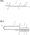
- Fig. 1 shows a catheter 1 which can be inserted into a vein and which has an expandable balloon 5 at the distal end.
- An expandable sheath 10 is arranged on this.
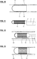
- the catheter 1 has a first channel 2, which fluidly connects a connection 2a to the balloon 5, and a second channel 3, which connects an inlet opening 3a to an outlet opening 3b.
- a syringe or the like can be connected to connection 2a, for example, in order to pump a fluid into the balloon 5 via the first channel 2 or to let it out again and thus enable the balloon 5 to inflate and deflate.
- air is not used as the fluid for inflating, but a liquid, for example a sodium chloride solution.
- a guide wire 4 can be received in the second channel 3.
- the balloon 5 and the envelope 10 are arranged in relation to the exit opening 3b in such a way that there is sufficient space to the side for the guide wire 4 to be guided past.
- the sheath 10 is shaped like a sack and is therefore open at the proximal sheath end 10a and closed at the distal sheath end 10b.
- the length of the sleeve 10 (distance between the ends 10a and 10b) is typically less than 10 cm in the non-expanded state.
- the envelope 10 is designed as a thin layer like a membrane and is impermeable to the blood, in particular the blood plasma.
- the sheath 10 is made of a body-compatible material, e.g., bovine pericardium. Another biological or synthetic material that is tolerated by the body and not rejected can also be used.
- the material of the cover 10, which is intended to remain in the body at least for a certain time, is soft so that it does not hurt and / or chafe when moving, especially when moving the hip joint when the cover 10 is used nearby.
- the material of the cover 10 is chosen so that it is not broken down by the body or that it dissolves after a certain time. In the latter case, the period of time until resorption is at least long enough that, when the device is used to close the cross, no neocross is formed.
- the device described here can be used in many ways to close a vein opening.
- Fig. 3 shows, for example, the confluence CM of the great saphenous vein VSM into the common femoral vein VFC ("Crosse").
- the superficial epigastric vein VES is also shown, which opens into the great saphenous vein VSM.
- the guide wire 4 is pushed into the vein VSM up to the cross CM and then the device according to FIG Fig. 1 Introduced into the VSM vein by sliding the second canal 3 over the wire 4. If the balloon 5 is together with the sheath 10 at the desired location, the guide wire 4 is removed. Then the balloon 5 is inflated. The shell 10 expands accordingly, cf. Fig. 3 . The sleeve 10 finally comes into contact with the vein wall and remains adhered there. The balloon 10 is deflated and removed from the VSM vein. The sheath 10 is now in place, as in FIG Fig. 4 shown.
- the Crosse CM is now closed and the VSM can be treated further, for example as described below in connection with the Fig. 17-19 explained.
- Fig. 5 shows another example in which the sheath 10 is analogous to that in the example according to FIG Fig. 4 has been set in such a way that the cross CP of the small saphenous vein VSP, which opens into the popliteal vein VP, is closed.
- the sheath 10 can adhere to the vein wall by means of at least one adhesive. This is designed in such a way that, together with the cover 10, a non-rigid structure is created which enables painless movements.
- the sheath 10 can, for example, have an outer layer which adheres there when it comes into contact with the vein wall.
- the outer layer is preferably expandable and can contain collagen, for example.
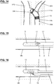
- Fig. 6 shows an example in which the casing 10 has a plurality of reservoirs all around on its surface, which contain a body-compatible adhesive 11 and are covered by a membrane 12.
- a body-compatible adhesive 11 When the balloon 5 is inflated, the membranes 12 burst and the adhesive 11 is released. If the balloon 5 is sufficiently expanded, as in Fig. 7 shown, the adhesive 11 comes into contact with the vein wall so that the sheath 10 is adhered thereto.
- a tissue adhesive for example one based on cyanoacrylate, is suitable as the adhesive 11.
- Fig. 8 shows an example in which the sleeve 10 is provided on the outside and circumferentially with hook elements 13 which are set up to engage the vein wall.
- the hook elements 13 When expanding the balloon 9, cf. Fig. 9 , the hook elements 13 come into contact with the vein wall VW and are finally anchored therein, cf. Fig. 10 .
- Fig. 11 shows an example in which the shell 10 is provided with a tubular lattice framework 14.
- This can, for example, be designed similar to a stent, but does not necessarily extend over the entire length of the sheath 10.
- the lattice framework 14 expands when the balloon 5 is expanded and remains in the expanded state when the balloon 5 is removed.
- the lattice framework 14 is arranged between the balloon 5 and the envelope 10. It can also be arranged on the outside of the casing 10.
- the lattice framework 14 can be attached to the shell 14.
- the lattice frame 14 is made of a body-compatible material, for example metal. Depending on the intended use, the material is absorbable.
- the balloon 5 together with the elements 10 and 14 arranged thereon is brought to the desired location in the vein and then inflated, cf. Fig. 12 until the sheath 10 rests against the vein wall VW.
- the balloon 5 is deflated and taken out.
- the sheath 10 is now fixed on the vein wall VW by means of the lattice framework 14, cf. Fig. 13 .
- Fig. 14 shows an example of a shell 10 with two lattice frames 14a, 14b, which has been placed in the cross CM.
- the respective lattice framework 14a, 14b is arranged on the shell 10, ie on or in the shell 10, and is preferably attached thereto.
- Figures 15 and 16 show variants in which an adhesive 11 can be applied to the surface of the envelope 10 within the vein after the balloon 5 has been placed but not yet expanded. The adhesive 11 is released and is distributed over the envelope 10. The balloon 5 is then inflated and the envelope 10 is thus glued to the vein wall VW.
- the further channel 18 is formed separately from the catheter 2, 3.
- the further channel 18 is introduced, for example, by means of a second venipuncture.
- Fig. 17-19 show a supplemented embodiment in which the device, in addition to the closure of a vein opening, enables the vein to be treated by applying a sclerosant and cutting it up.
- This treatment is in the patent EP3135206B1 by the same applicant.
- the catheter 1 ' is an external catheter and has the balloon 5 with the expandable sheath 10 at the distal end. As Fig. 19 shows, the balloon 5 is fluidically connected to the connection 2a at the proximal end via a first channel 2.
- the catheter 1 ' has the second channel 3, which connects the inlet opening 3a with the outlet opening 3b and in which a guide wire can be received.
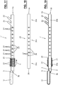
- the catheter 1 ' is fenestrated.
- it is provided with side openings 24 (“catheter window”) between the balloon 20 and the connections 2a, 22. These are arranged distributed around the circumference of the catheter 1 'and are fluidically connected to the inlet opening 3 a via the channel 3.
- a sclerosant can be injected into the vein to be treated via the side openings 24.
- Two adjacent side openings 24 are arranged axially and radially offset from one another. The offset allows the most homogeneous possible distribution of sclerosant in the vein.
- Markings 23 are provided on the catheter shaft between the balloon 20 and the connections 2a, 22, which markings are attached, for example, at regular intervals and, among other things, provide information about how far the catheter 1 'has been inserted into a vein.
- markings 23 in the form of lines and numbers 0, 10, 20, 30, ..., 80 can be seen. Of course, other types of markings are also possible.
- the side openings 24 are arranged in groups, so that the part of the catheter 1 ′ provided with the side openings 24 is divided into sections which each have the same arrangement of side openings 24.
- a group with three side openings can be seen between sections 0 to 10.
- the same arrangement of side openings is repeated in the respective subsequent section 10 to 20, 20 to 30, etc.
- the side openings 24 in the respective group are arranged radially offset by an angle. In the example with three side openings, this angle can be 120 degrees. However, an uneven radial distribution is also conceivable.
- the number of side openings 24 per group or section can differ from that in FIG Fig. 17 be shown and be one, two or more. Since the side openings 24 extend through the outer wall of the catheter 1 ', the number and arrangement are selected so that enough space remains to be able to provide the channels from the connections 2a and 22 to the balloons 5 and 20.
- a second catheter 30 (hereinafter also “inner catheter”) can be introduced via the inlet opening 3a of the catheter 1 ′, as shown in FIG Fig. 18 is shown.
- the catheter 30 has a distal end section 30a and a proximal end section 30b with a connector 34.
- the distal end section 30a is formed by a closed wall.
- the end 36 of the end section 30a is free of an end opening.
- the closed end 36 of the inner catheter 30 allows the lumen at the tip of the outer catheter 1 'to be closed, which prevents it from flowing away through the outlet opening 3b when sclerosant is used.
- the catheter 30 has an intermediate part 30c which has an inner channel (“lumen”) and which is provided with side openings 37. These are fluidically connected to the connection 34 via the inner channel. Subsequent to the distal closed end section 30a, the catheter 30 is only provided with side openings 37 on a partial section, while the rest of the catheter shaft has no openings. In contrast to the external catheter 1 ′, only a single group of side openings 37 is therefore provided.
- the number and / or arrangement of the side openings 37 preferably corresponds to the number or arrangement of the first group of side openings 24 in the external catheter 1 '. In the example according to Fig.
- three side openings 37 can be seen, which are arranged radially and axially offset to one another, similar to the side openings 24 in a group in the outer catheter 1 'according to FIG Fig. 17 .
- the number of side openings 37 can be one, two or more.
- Markings 38 are provided along the intermediate part 30c of the catheter 30, which are attached, for example, at regular intervals and, among other things, provide information about how far the catheter 30 is inserted into the outer catheter 1 '. Lines, numbers, etc. serve as markings 38.
- the outer shape of the inner catheter 30 is designed in such a way that space can be provided in the outer catheter 1 ′ for the channel 2 to the balloon 5 and for the channel to the balloon 20.
- the inner catheter 30 is received in the outer catheter 1 'and then withdrawn in sections.
- the side openings 38 are located here first near the side openings 24 of the first group, then near the side openings 24 of the second group, etc.
- the closed end section 30a of the inner catheter 30 seals the channel 3 of the outer catheter 1 'between the ends 3b and 36.
- a sclerosant can thus be introduced into the vein to be treated in sections via the connection 34 and the side openings 37 and 24.
- the balloon 20 is in the Figures 17 and 19 is shown in a slightly inflated condition.
- the direction in which the axis A runs, along which the outer catheter 1 ′ extends from the outlet opening 3b to the inlet opening 3a, is referred to as "axial", while “radial” is transverse to the axis A.
- the balloon 20 is a “cutting balloon” and has one or more cutting elements 21 (“blades”) for this purpose.
- a respective cutting element 32 does not run straight when viewed in the axial direction A.
- the cutting edge of a cutting element can be curved so that it winds around axis A, e.g., helically. It is also conceivable that, viewed in the direction of the axis A, the cutting edge has a section with a straight axial course which merges again into a straight section via a curved intermediate section. It is also conceivable to provide only a single cutting element 3 which runs around the axis A.
- the uneven course of a cutting element 3 means that, viewed in the axial direction A, the ends of a cutting element 3 are arranged radially offset by an angle which is greater than 0 degrees.
- the angle is preferably at least 10 degrees and particularly preferably at least 20 degrees.
- the course can be such that said angle is less than 360 degrees. It is preferably at most 180 degrees and particularly preferably at most 90 degrees.
- the maximum extension of a cutting element 21 transversely to the axis A can also be variable, in that the cutting edge runs at a height which decreases in the direction of the connection 3a.
- the cutting element 21 is wedge-shaped.
- the maximum height H of a cutting element 21 is typically in the range of 0.5-1.5 mm.
- the balloon 21 extends axially over a length which is typically in the range of 5-30 mm.
- the axially or radially variable shape of a cutting element 21 allows a comprehensive mechanical action on an inner wall of the vein when the catheter 1 'inserted into the vein is withdrawn again.
- the tapering cutting edges of the cutting elements 21 gradually dig into the inner wall of the veins, similar to a plow. An abrupt mechanical action is therefore avoided, so that a more painless treatment is possible, which under certain circumstances can also be carried out without local anesthesia in the form of a tumescent anesthesia. This is the case, for example, when Aethoxysklerol® is used as a sclerosant, which is also a local anesthetic.
- the device according to Fig. 17-19 can be used, for example, as follows: The catheter 1 'is inserted into the trunk vein VSM, if necessary by means of a guide wire, and the sheath 10 is placed by inflating and deflating the balloon 5 so that the cross CM is closed, cf. Fig. 4 .
- the balloon 20 is then inflated.
- the inner catheter 20 is pushed into the channel 3 of the outer catheter 1 ', unless it has already been introduced together with the catheter 1' in the event that no guide wire has been used.
- the sclerosant is supplied via the inner catheter 20 by means of a syringe attached to the connection 34.
- the inner catheter 30 is withdrawn in e.g. 10 cm steps. Sclerosant is applied every 10 cm and a certain time, e.g. approx. 1 minute, is waited before the next section is treated. The procedure is continued until the entire inner catheter 30 is removed.
- the device comprises a catheter 41 which has a first channel which connects an inlet opening 43a to the outlet opening 43b and which is used to receive a guide wire 4 (cf. Fig. 2 ) is designed.
- a balloon 45 is arranged at the distal end of the catheter 41. This runs around the outer wall of the catheter 41 so that the first channel can extend through the balloon 45 and the exit opening 43b is axially offset from the balloon 45.
- the balloon 45 is fluidically connected to a connector 42a at the proximal end of the catheter 41 via a second channel. A fluid can be conveyed via the second channel in order to be able to inflate and deflate the balloon 45.
- An expandable envelope 50 is arranged on the balloon 45. Like the sheath 10 in the first exemplary embodiment, this is designed as a membrane and can consist of the same material.
- the length of the sleeve 50 (distance between the ends 50a and 50b) is typically less than 10 cm in the non-expanded state.
- the device according to Fig. 20 can be used, for example, to close a vein opening into a perforating vein.
- Fig. 21 shows schematically a perforating vein PV, which connects a superficial vein OV with a deep vein TV.
- the perforating vein PV is insufficient and should be shut down. To do this, proceed as follows: After the guide wire 4 has been pushed under ultrasound control via the vein OV into the area of the perforating vein PV to be treated, the catheter becomes 41 is advanced along the guide wire 4 until the balloon 45, together with the sheath 50, covers the perforating vein PV. The guide wire 4 is removed and the balloon 45 is inflated until the sheath 50 contacts the vein wall VW, cf. Fig. 21 . Because of the adhesive, the sheath 50 remains adhered to the vein wall VW. The balloon 45 is deflated and removed by pulling out the catheter 41. The vein opening into the perforating vein PV is now closed by means of the sheath 50, cf. Fig. 22 .
- Fig. 20 can also be used for the treatment of the Magnacrosse CM.
- Fig. 23 shows the situation in which the sheath 50, which is open on both sides, has been placed in such a way that the open end 50b extends into the superficial epigastric vein VES, whereby the connection to the common femoral vein VFC is sealed.
- the sheath 50 in such a way that it closes the great saphenous vein VSM or its cross CM from the common femoral vein VFC, cf. Fig. 25 .
- Fig. 24 shows some leg veins, namely popliteal vein VP, femoral vein VF, common femoral vein VFC, deep femoral vein VPF and great saphenous vein VSM.
- the catheter 41 with the balloon 45 and the sheath 50 is introduced into the popliteal vein VP and thus into the deep leg vein system via a puncture in the hollow of the knee.
- the balloon 45 and envelope 50 are pushed up over the femoral vein VF into the common femoral vein VPF and the envelope is placed at the magnacross CM.
- the devices described herein can be designed for single use and are provided in sterile form in packages.
- the cutting device 20, 21 and / or the side openings 24 in the variant according to FIG Fig. 17 can also be formed on a separately formed catheter which can be inserted into the vein after the sheath 10, 50 has been placed and the device according to FIG Fig. 1 or 20 has been removed.
Landscapes
- Health & Medical Sciences (AREA)
- Life Sciences & Earth Sciences (AREA)
- Surgery (AREA)
- Biomedical Technology (AREA)
- Engineering & Computer Science (AREA)
- Public Health (AREA)
- Heart & Thoracic Surgery (AREA)
- Veterinary Medicine (AREA)
- Animal Behavior & Ethology (AREA)
- General Health & Medical Sciences (AREA)
- Vascular Medicine (AREA)
- Nuclear Medicine, Radiotherapy & Molecular Imaging (AREA)
- Medical Informatics (AREA)
- Molecular Biology (AREA)
- Reproductive Health (AREA)
- Cardiology (AREA)
- Oral & Maxillofacial Surgery (AREA)
- Transplantation (AREA)
- Epidemiology (AREA)
- Chemical & Material Sciences (AREA)
- Chemical Kinetics & Catalysis (AREA)
- Media Introduction/Drainage Providing Device (AREA)
Abstract
Die Vorrichtung zum Verschliessen einer Veneneinmündung bei der Behandlung der Varikose umfasst einen in ein Venensystem einführbaren Katheter (1), an dessen distalen Ende ein aufweitbarer Ballon (5) angeordnet ist, eine Hülle (10), welche umlaufend auf dem Ballon angeordnet ist und mittels diesem aufweitbar ist, wobei das proximale Hüllenende offen ausgestaltet ist, und mindestens ein Haftmittel zum Einwirken auf die aufgeweitete Hülle derart, dass sie zum Verschliessen der Veneneinmündung an einer Venenwand anhaftet.The device for closing a vein opening in the treatment of varicose veins comprises a catheter (1) which can be inserted into a venous system and at the distal end of which an expandable balloon (5) is arranged, a sheath (10) which is arranged circumferentially on the balloon and by means of this is expandable, wherein the proximal end of the sheath is designed to be open, and at least one adhesive for acting on the expanded sheath in such a way that it adheres to a vein wall to close the vein opening.
Description
Die Erfindung betrifft eine Vorrichtung zum Verschliessen einer Veneneinmündung bei der Behandlung der Varikose.The invention relates to a device for closing a vein opening in the treatment of varicose veins.
Es sind neuere endovenöse Verfahren zur Behandlung der Varikose bekannt, bei welchen Laser, Radiofrequenz oder Kleber zum Verkleben eingesetzt werden. Diese Verfahren sind bei der Behandlung der Vena saphena magna oder der Vena saphena parva problematisch, da die Crosse (auf Englisch "saphenofemoral junction" bzw. "saphenopopliteal junction") nicht genau verschlossen werden kann. Kommt man bei der Behandlung zu nahe an die Crosse, so droht die Gefahr einer Thrombose und Embolie. Ist die Behandlung zu weit weg von der Crosse, kann es zu einem Rezidiv kommen.There are newer endovenous methods known for treating varicose veins, in which laser, radio frequency or glue are used for gluing. These procedures are problematic in the treatment of the great saphenous vein or the small saphenous vein, since the cross (in English "saphenofemoral junction" or "saphenopopliteal junction") cannot be closed exactly. If you get too close to the cross during treatment, there is a risk of thrombosis and embolism. If the treatment is too far from the cross, a relapse can occur.
Bei der Varikose können auch die Perforansvenen betroffen sein, bei welchen die physiologische Flussrichtung von der oberflächlichen Venen in die tiefen Venen gerichtet ist. Bei der Insuffizienz der Perforansvenen kommt es zu einer Strömungsumkehr in den Perforansvenen, mit Stauungen der oberflächlichen Venen. Die eingangs erwähnten endovenösen Verfahren bieten keine optimale Lösung, um auch das Problem der insuffizienten Perforansvenen behandeln zu können.In the case of varicose veins, the perforating veins can also be affected, in which the physiological direction of flow is directed from the superficial veins into the deep veins. In the case of insufficiency of the perforating veins, there is a reversal of flow in the perforating veins, with congestion of the superficial veins. The endovenous procedures mentioned at the beginning do not offer an optimal solution for treating the problem of insufficient perforating veins.
Es ist eine Aufgabe der vorliegenden Erfindung, eine Vorrichtung anzugeben, die ein sicheres Verschliessen einer Veneneinmündung bei der Behandlung der Varikose ermöglicht.It is an object of the present invention to provide a device which enables a vein opening to be securely closed in the treatment of varicose veins.
Eine Vorrichtung, die diese Aufgabe löst, ist im Patentanspruch 1 angegeben. Die weiteren Patentansprüche geben bevorzugte Ausführungen der Vorrichtung an.A device that achieves this object is specified in
Die Vorrichtung gemäss Anspruch 1 umfasst eine Hülle, welche mittels eines Ballons aufweitbar ist, um eine Veneneinmündung zu verschliessen.The device according to
Die Vorrichtung ist für unterschiedliche Anwendungen auslegbar. In einer Anwendung kann die Crosse der Vena saphena magna/parva millimetergenau abgedichtet werden, so dass keine Thrombose ins tiefe Beinvenensystem gelangen kann und kein frühes Varizenrezidiv droht.The device can be designed for different applications. In one application, the cross of the great saphenous / parva vein can be sealed with millimeter precision so that no thrombosis can penetrate the deep leg vein system and there is no risk of early variceal recurrence.
In einer anderen Anwendung kann eine Perforansvene sicher abgedichtet werden, so dass der Reflux in ihrem Bereich behoben werden kann, ohne dass durch diese Intervention das tiefe Beinvenensystem gefährdet wird.In another application, a perforating vein can be securely sealed so that the reflux in its area can be eliminated without endangering the deep leg vein system as a result of this intervention.
Die Vorrichtung ist unterschiedlich ausgestaltbar. Die Hülle der Vorrichtung beispielsweise kann einen röhrenförmigen Mittelteil aufweisen, der entweder nur an einem Hüllenende oder an beiden Hüllenenden offen ausgestaltet ist. Die Hülle ist z.B. sackartig ausgebildet, so dass mit ihr im aufgeweiteten Zustand ein Freiraum in der Vene abgrenzbar ist, der an den einem Ende verschlossen und an dem anderen Ende offen ist. In einer anderen Ausführungsform ist die Hülle durchgehend röhrenförmig ausgebildet, so dass mit ihr im aufgeweiteten Zustand ein Freiraum in der Vene abgrenzbar ist, der an den beiden Enden offen ist.The device can be configured in different ways. The casing of the device, for example, can have a tubular central part which is designed to be open either only at one casing end or at both casing ends. The sheath is, for example, sack-like so that, in the expanded state, it can be used to delimit a free space in the vein that is closed at one end and open at the other end. In another embodiment, the sheath is continuously tubular, so that in the expanded state it can be used to define a free space in the vein which is open at both ends.
Weitere spezifische Konstruktionsmerkmale der Vorrichtung und deren Vorteile sind aus folgender Beschreibung und Zeichnungen von Ausführungsbeispielen ersichtlich. Es zeigen
-
Fig. 1 ein erstes Ausführungsbeispiel einer Vorrichtung in einer Seitenansicht, -
Fig. 2 den vorderen Teil der Vorrichtung gemässFig. 1 zusammen mit einem Führungsdraht in einer geschnittenen Seitenansicht, -
Fig. 3 eine schematische Ansicht der Venen im Bereich der Crosse der Vena saphena magna mit eingeführter Vorrichtung gemässFig. 1 , -
Fig. 4 die Ansicht gemässFig. 3 nach der Behandlung, wobei die Hülle geschnitten dargestellt ist, -
Fig. 5 eine schematische Ansicht der Venen im Bereich der Crosse der Vena saphena parva nach der Behandlung, wobei die Hülle geschnitten dargestellt ist, -
Fig. 6 den vorderen Teil einer Variante der Vorrichtung in einer teilweise geschnittenen Seitenansicht, -
Fig. 7 die Vorrichtung gemässFig. 6 in einer Vene, wobei Ballon und Hülle im aufgeweiteten Zustand sind, -
Fig. 8 den vorderen Teil einer weiteren Variante der Vorrichtung in einer teilweise geschnittenen Seitenansicht, -
Fig. 9 die Vorrichtung gemässFig. 9 in einer Vene, wobei Ballon und Hülle in einem aufgeweiteten Zustand sind, -
Fig. 10 die Ansicht gemässFig. 9 nach der Behandlung, -
Fig. 11 den vorderen Teil einer anderen weiteren Variante der Vorrichtung in einer Seitenansicht, wobei die Hülle geschnitten dargestellt ist, -
Fig. 12 die Vorrichtung gemässFig. 11 in einem etwas aufgeweiteten Zustand in einer Vene, -
Fig. 13 die Ansicht gemässFig. 12 nach der Behandlung, -
Fig. 14 eine schematische Ansicht der Venen im Bereich der Crosse der Vena saphena magna, in welche eine Hülle mit Gittergerüsten platziert worden ist, wobei die Hülle geschnitten dargestellt ist, -
Fig. 15 den vorderen Teil einer weiteren Variante der Vorrichtung in einer Vene, -
Fig. 16 den vorderen Teil einer anderen weiteren Variante der Vorrichtung in einer Vene, -
Fig. 17 eine anderen weitere Variante der Vorrichtung ohne Innenkatheter in einer Seitenansicht, -
Fig. 18 den Innenkatheter für die Vorrichtung gemässFig. 17 in einer Seitenansicht, -
Fig. 19 die Vorrichtung gemässFig. 17 mit eingeführtem Innenkatheter gemässFig. 18 in einer teilweise geschnittenen Seitenansicht, -
Fig. 20 ein zweites Ausführungsbeispiel einer Vorrichtung in einer Seitenansicht, -
Fig. 21 eine schematische Ansicht der Venen im Bereich einer Perforansvene mit eingeführter Vorrichtung gemässFig. 20 , -
Fig. 22 die Ansicht gemässFig. 21 nach der Behandlung, wobei die Hülle geschnitten dargestellt ist, -
Fig. 23 eine schematische Ansicht der Venen im Bereich der Crosse der Vena saphena magna nach der Behandlung mit der Vorrichtung gemässFig. 20 , wobei die Hülle geschnitten dargestellt ist, -
Fig. 24 schematisch ein Bein mit einem Teil des Venensystems, und -
Fig. 25 eine schematische Ansicht der Venen im Bereich der Crosse der Vena saphena magna nach der Behandlung mit der Vorrichtung gemässFig. 20 , wobei die Hülle geschnitten dargestellt ist.
-
Fig. 1 a first embodiment of a device in a side view, -
Fig. 2 the front part of the device according toFig. 1 together with a guide wire in a sectional side view, -
Fig. 3 a schematic view of the veins in the region of the cross of the great saphenous vein with the device inserted according to FIGFig. 1 , -
Fig. 4 the view according toFig. 3 after the treatment, with the shell shown in section, -
Fig. 5 a schematic view of the veins in the area of the cross of the small saphenous vein after the treatment, the sheath being shown in section, -
Fig. 6 the front part of a variant of the device in a partially sectioned side view, -
Fig. 7 the device according toFig. 6 in a vein with the balloon and envelope expanded, -
Fig. 8 the front part of a further variant of the device in a partially sectioned side view, -
Fig. 9 the device according toFig. 9 in a vein with the balloon and envelope in an expanded state, -
Fig. 10 the view according toFig. 9 after treatment, -
Fig. 11 the front part of another further variant of the device in a side view, the shell being shown in section, -
Fig. 12 the device according toFig. 11 in a slightly dilated state in a vein, -
Fig. 13 the view according toFig. 12 after treatment, -
Fig. 14 a schematic view of the veins in the area of the cross of the great saphenous vein, in which a sheath with lattice frameworks has been placed, the sheath being shown in section, -
Fig. 15 the front part of another variant of the device in a vein, -
Fig. 16 the front part of another further variant of the device in a vein, -
Fig. 17 another further variant of the device without inner catheter in a side view, -
Fig. 18 the inner catheter for the device according toFig. 17 in a side view, -
Fig. 19 the device according toFig. 17 with inserted inner catheter according toFig. 18 in a partially sectioned side view, -
Fig. 20 a second embodiment of a device in a side view, -
Fig. 21 a schematic view of the veins in the area of a perforating vein with an inserted device according to FIGFig. 20 , -
Fig. 22 the view according toFig. 21 after the treatment, with the shell shown in section, -
Fig. 23 a schematic view of the veins in the area of the cross of the great saphenous vein after treatment with the device according to FIGFig. 20 , with the shell shown in section, -
Fig. 24 schematically a leg with part of the venous system, and -
Fig. 25 a schematic view of the veins in the area of the cross of the great saphenous vein after treatment with the device according to FIGFig. 20 , the shell is shown in section.
In der nachfolgenden Beschreibung werden die Begriffe "proximal" und "distal" aus Sicht des Benutzers der Vorrichtung verwendet. Das proximale Ende ist somit das Ende, welches dem Benutzer zugewandt ist, und das distale Ende ist das dem Benutzer abgewandte Ende.In the following description, the terms “proximal” and “distal” are used from the perspective of the user of the device. The proximal end is thus the end facing the user and the distal end is the end facing away from the user.
Am Anschluss 2a ist z.B. eine Spritze oder drgl. anschliessbar, um über den ersten Kanal 2 ein Fluid in den Ballon 5 zu pumpen bzw. aus diesem wieder abzulassen und so ein In- und Deflatieren des Ballons 5 zu ermöglichen. Um einen Patienten durch eine etwaige Undichtigkeit des in die Vene eingeführten Ballons 5 nicht zu gefährden, wird nicht Luft als Fluid zum Inflatieren verwendet, sondern eine Flüssigkeit, beispielsweise eine Natriumchloridlösung.A syringe or the like can be connected to
Wie
Die Hülle 10 ist sackartig geformt und somit am proximalen Hüllenende 10a offen und am distalen Hüllenende 10b geschlossen ausgestaltet. Die Länge der Hülle 10 (Distanz zwischen den Enden 10a und 10b) ist im nicht-aufgeweiteten Zustand typischerweise kleiner als 10 cm.The
Die Hülle 10 ist wie eine Membrane als dünne Schicht ausgebildet und ist für das Blut, insbesondere das Blutplasma, undurchlässig.The
Die Hülle 10 besteht aus einem körperverträglichen Material, z.B. Rinderperikard. Es kann auch ein anderes biologisches oder auch synthetisches Material verwendet werden, das vom Körper toleriert und nicht abgestossen wird. Das Material der Hülle 10, welches im Körper zumindest für eine gewisse Zeit verbleiben soll, ist weich, so dass sie bei Bewegungen nicht schmerzt und/oder scheuert, insbesondere bei Bewegungen im Hüftgelenk, wenn die Hülle 10 in der Nähe eingesetzt wird.The
Je nach Anwendungszweck ist das Material der Hülle 10 so gewählt, dass es vom Körper nicht abgebaut wird oder sich nach einer gewissen Zeit auflöst. Im letzteren Fall ist die Zeitdauer bis zur Resorption mindestens so lange, dass bei Verwendung der Vorrichtung zum Verschliessen der Crosse es nicht zur Bildung einer Neocrosse kommt.Depending on the intended use, the material of the
Die hier beschriebene Vorrichtung ist vielseitig anwendbar, um eine Veneneinmündung zu verschliessen.The device described here can be used in many ways to close a vein opening.
Bei der Anwendung wird der Führungsdraht 4 in der Vene VSM bis zur Crosse CM gestossen und dann die Vorrichtung gemäss
Die Crosse CM ist nun verschlossen, und die Vene VSM kann weiter behandelt werden, z.B. so wie unten im Zusammenhang mit den
Das Anhaften der Hülle 10 an der Venenwandung ist durch mindestens ein Haftmittel erzielbar. Dieses ist so ausgelegt, dass zusammen mit der Hülle 10 ein nicht-starres Gebilde entsteht, welches schmerzfreie Bewegungen ermöglicht.The
Ein Haftmittel ist in vielfältiger Weise bereitstellbar:
Die Hülle 10 kann z.B. eine Aussenschicht aufweisen, die beim Kontakt mit der Venenwand dort haften bleibt. Die Aussenschicht ist vorzugsweise aufweitbar und kann z.B. Kollagen enthalten.An adhesive can be provided in a variety of ways:
The
Bei der Anwendung wird der Ballon 5 zusammen den darauf angeordneten Elementen 10 und 14 an die gewünschte Stelle in der Vene gebracht und anschliessend inflatiert, vgl.
Als Alternative zu der Ausführungsform gemäss
Bei der Variante gemäss
Bei der Variante gemäss
Der Katheter 1' ist ein Aussenkatheter und weist am distalen Ende den Ballon 5 mit der aufweitbaren Hülle 10 auf. Wie
Auf dem Katheter 1' ist nachfolgend zum Ballon 5 ein weiterer Ballon 20 mit Schneidelementen 21 angeordnet. Der weitere Ballon 20 ist über einen weiteren (hier nicht dargestellten) Kanal fluidisch mit einem weiteren Anschluss 22 am proximalen Ende des Katheters 1' verbunden. So wie beim Ballon 5 und dem Anschluss 2a kann über den Anschluss 22 ein Fluid in den Ballon 20 gepumpt werden, um diesen zu Inflatieren.A
Der Katheter 1' ist fenestriert. Zu diesem Zweck ist er zwischen dem Ballon 20 und den Anschlüssen 2a, 22 mit Seitenöffnungen 24 ("Katheterfenster") versehen. Diese sind um den Umfang des Katheters 1' herum verteilt angeordnet und über den Kanal 3 fluidisch mit der Eingangsöffnung 3a verbunden. Bei der Anwendung ist über die Seitenöffnungen 24 ein Sklerosierungsmittel in die zu behandelnde Vene injizierbar. Zwei benachbarte Seitenöffnungen 24 sind axial und radial versetzt zueinander angeordnet. Der Versatz erlaubt eine möglichst homogene Verteilung von Sklerosierungsmittel in der Vene.The catheter 1 'is fenestrated. For this purpose, it is provided with side openings 24 (“catheter window”) between the
Zwischen dem Ballon 20 und den Anschlüssen 2a, 22 sind auf dem Katheterschaft Markierungen 23 vorgesehen, die beispielsweise in regelmässigen Abständen angebracht sind und u.a. Angaben darüber liefern, wie weit der Katheter 1' in eine Vene eingeführt ist. In der Variante gemäss
Die Seitenöffnungen 24 sind in Gruppen angeordnet, so dass der mit den Seitenöffnungen 24 versehene Teil des Katheters 1' in Abschnitte unterteilt ist, die jeweils die gleiche Anordnung an Seitenöffnungen 24 aufweist. Im Beispiel gemäss
Über die Eingangsöffnung 3a des Katheters 1' ist ein zweiter Katheter 30 (im Folgenden auch "Innenkatheter") einführbar, wie er in
Zwischen den beiden Endabschnitten 30a und 30b weist der Katheter 30 einen Zwischenteil 30c auf, der einen Innenkanal ("Lumen") aufweist und der mit Seitenöffnungen 37 versehen ist. Diese sind über den Innenkanal fluidisch mit dem Anschluss 34 verbunden. Der Katheter 30 ist anschliessend zum distalen geschlossenen Endabschnitt 30a lediglich auf einem Teilabschnitt mit Seitenöffnungen 37 versehen, während der übrige Katheterschaft keine Öffnungen aufweist. Es ist somit im Gegensatz zum Aussenkatheter 1' nur eine einzelne Gruppe an Seitenöffnungen 37 vorgesehen. Vorzugsweise entspricht die Anzahl und/oder Anordnung der Seitenöffnungen 37 der Anzahl bzw. Anordnung der ersten Gruppe an Seitenöffnungen 24 beim Aussenkatheter 1'. Im Beispiel gemäss
Entlang des Zwischenteils 30c des Katheters 30 sind Markierungen 38 vorgesehen, die beispielsweise in regelmässigen Abständen angebracht sind und u.a. Angaben darüber liefern, wie weit der Katheter 30 in den Aussenkatheter 1' eingeführt ist. Als Markierungen 38 dienen z.B. Striche, Zahlen, etc.
Die Aussenform des Innenkatheters 30 ist so gestaltet, dass im Aussenkatheter 1' Platz für den Kanal 2 zum Ballon 5 sowie für den Kanal zum Ballon 20 vorgesehen werden kann.The outer shape of the
Bei der Anwendung wird der Innenkatheter 30 im Aussenkatheter 1' aufgenommen und dann abschnittsweise zurückgezogen. Dabei befinden sich die Seitenöffnungen 38 zuerst in der Nähe der Seitenöffnungen 24 der ersten Gruppe, anschliessend bei den Seitenöffnungen 24 der zweiten Gruppe, usw. Der verschlossene Endabschnitt 30a des Innenkatheters 30 dichtet dabei den Kanal 3 des Aussenkatheters 1' zwischen den Enden 3b und 36 ab. Über den Anschluss 34 und die Seitenöffnungen 37 und 24 ist somit ein Sklerosierungsmittel abschnittsweise in die zu behandelnde Vene einleitbar.During use, the
Der Ballon 20 ist in den
Der Ballon 20 ist ein "Cutting Balloon" und weist zu diesem Zweck ein oder mehrere Schneidelemente 21 ("Klingen") auf. Ein jeweiliges Schneidelement 32 verläuft in axialer Richtung A gesehen nicht gerade.The
Es sind vielfältige Formen an Verläufen denkbar. Beispielsweise kann die Schnittkante eines Schneidelements so gekrümmt sein, dass sie sich um die Achse A windet, z.B. schraubenförmig. Es ist auch denkbar, dass in Richtung der Achse A gesehen die Schnittkante einen Abschnitt mit einem geraden axialen Verlauf aufweist, der über einen gekrümmten Zwischenabschnitt wieder in einen geraden Abschnitt übergeht. Es ist auch denkbar, nur ein einzelnes Schneidelement 3 vorzusehen, welches um die Achse A verläuft.Diverse forms of gradients are conceivable. For example, the cutting edge of a cutting element can be curved so that it winds around axis A, e.g., helically. It is also conceivable that, viewed in the direction of the axis A, the cutting edge has a section with a straight axial course which merges again into a straight section via a curved intermediate section. It is also conceivable to provide only a
Der ungerade Verlauf eines Schneidelements 3 führt dazu, dass gesehen in der axialen Richtung A die Enden eines Schneidelements 3 um einen Winkel radial versetzt angeordnet sind, der grösser als 0 Grad ist. Bevorzugt beträgt der Winkel mindestens 10 Grad und besonders bevorzugt mindestens 20 Grad. Im Weiteren kann der Verlauf so sein, dass besagter Winkel weniger als 360 Grad ist. Bevorzugt beträgt er höchstens 180 Grad und besonders bevorzugt höchstens 90 Grad.The uneven course of a
Die maximale Ausdehnung eines Schneidelements 21 quer zur Achse A kann ebenfalls veränderlich sein, indem die Schneidkante auf einer Höhe verläuft, die in Richtung zum Anschluss 3a hin abnimmt. Im vorliegenden Ausführungsbeispiel ist das Schneidelement 21 keilförmig ausgebildet. Die maximale Höhe H eines Schneidelements 21 ist typischerweise im Bereich von 0.5 - 1.5 mm.The maximum extension of a cutting
Der Ballon 21 erstreckt sich axial auf einer Länge, welche typischerweise im Bereich von 5 - 30 mm liegt.The
Die sich axial bzw. radial veränderliche Formgebung eines Schneidelements 21 erlaubt eine umfassende mechanische Einwirkung auf eine Veneninnenwand, wenn der in die Vene eingeführte Katheter 1' wieder herausgezogen wird. Dabei graben sich die sich verjüngenden Schneidkanten der Schneidelemente 21 ähnlich eines Pflugs allmählich in die Veneninnenwand ein. Es wird daher eine abrupte mechanische Einwirkung vermieden, so dass eine schmerzfreiere Behandlung möglich ist, die unter Umständen auch ohne örtliche Betäubung in Form einer Tumeszenzanästhesie erfolgen kann. Dies ist z.B. dann der Fall, wenn Aethoxysklerol® als Sklerosierungsmittel eingesetzt wird, das ja auch ein Lokalanästhetikum ist.The axially or radially variable shape of a cutting
Die Vorrichtung gemäss
Der Katheter 1' wird gegebenenfalls mittels Führungsdraht in die Stammvene VSM eingeführt und die Hülle 10 durch In- und Deflatieren des Ballons 5 platziert, so dass die Crosse CM verschlossen ist, vgl.
The catheter 1 'is inserted into the trunk vein VSM, if necessary by means of a guide wire, and the
Anschliessend wird der Ballon 20 inflatiert. Der Innenkatheter 20 wird in den Kanal 3 des Aussenkatheters 1' einschoben, sofern er nicht schon zusammen mit dem Katheter 1' eingeführt worden ist im Falle, dass kein Führungsdraht verwendet wurde.The
Mittels einer am Anschluss 34 angebrachten Spritze wird über den Innenkatheter 20 das Sklerosierungsmittel zugeführt. Der Innenkatheter 30 wird in z.B. 10 cm-Schritten herausgezogen. Pro 10 cm wird jeweils Sklerosierungsmittel appliziert und eine bestimmte Zeit, z.B. ca. 1 Minute, gewartet, bevor der nächste Abschnitt behandelt wird. Es wird so weiterverfahren, bis der gesamte Innenkatheter 30 entfernt ist.The sclerosant is supplied via the
Die Einwirkung des Sklerosierungsmittels hat zu einem Vasospasmus geführt. Zudem sollte auch die Schmerzempfindlichkeit vermindert sein. Nun wird der Katheter 1 mit dem inflatierten Ballon 20 langsam zurückgezogen. Durch die mechanische Einwirkung eines Schneidelements 21 auf dem Ballon 20 wird die Intima und Media der Vene zerstört. Die spezielle Formgebung eines Schneidelements 21 erlaubt eine wirksame Zerstörung der Veneninnenwand, die beim Zurückziehen des Ballons 20 in multiple Fragmente zerschnitten wird.Exposure to the sclerosant has caused vasospasm. In addition, the sensitivity to pain should also be reduced. The
Beim in
Auf dem Ballon 45 ist eine aufweitbare Hülle 50 angeordnet. Diese ist wie die Hülle 10 beim ersten Ausführungsbeispiel als Membran ausgebildet und kann aus demselben Material bestehen.An
Im Gegensatz zur Hülle 10 ist die Hülle 50 beidseitig an beiden Hüllenenden 50a, 50b offen und somit durchgehen röhrenförmig ausgestaltet.In contrast to the
Die Länge der Hülle 50 (Distanz zwischen den Enden 50a und 50b) ist im nicht-aufgeweiteten Zustand typischerweise kleiner als 10 cm.The length of the sleeve 50 (distance between the
Zur Fixation der Hülle 50 an einer Venenwand ist mindestens ein Haftmittel vorgesehen, das so ausgestaltet sein kann wie beim ersten Ausführungsbeispiel: Vorsehen einer haftenden Aussenschicht auf der Hülle 50, Vorsehen von Klebstoff 12 mittels Reservoir 11 und/oder durch einen weiteren Kanal 17, 18, Vorsehen von Hakenelementen 13, Vorsehen eines oder mehrerer aufweitbaren Gittergerüsten 14, etc.To fix the
Die Vorrichtung gemäss
Nachdem der Führungsdraht 4 unter Ultraschallkontrolle über die Vene OV in den Bereich der zu behandelnden Perforansvene PV gestossen worden ist, wird der Katheter 41 entlang des Führungsdrahts 4 soweit vorgeschoben, bis der Ballon 45 zusammen mit der Hülle 50 die Perforansvene PV abdeckt. Der Führungsdraht 4 wird entfernt und der Ballon 45 wird inflatiert, bis die Hülle 50 die Venenwandung VW kontaktiert, vgl.
After the
Die Vorrichtung gemäss
Als weitere Anwendungsvariante ist es möglich, die Hülle 50 so zu setzen, dass sie die Vena saphena magna VSM bzw. ihre Crosse CM von der Vena femoralis communis VFC aus verschliesst, vgl.
Der Katheter 41 mit dem Ballon 45 und der Hülle 50 wird über eine Punktion in der Kniekehle in die Vena poplitea VP und damit ins tiefe Beinvenensystem eingebracht. Ballon 45 und Hülle 50 werden über die Vena femoralis VF bis in die Vena femoralis communis VPF hochgeschoben und die Hülle bei der Magnacrosse CM platziert.The
Die hier beschriebenen Vorrichtungen können für einen Einweggebrauch ausgelegt werden und sind in steriler Form in Verpackungen bereitgestellt.The devices described herein can be designed for single use and are provided in sterile form in packages.
Aus der vorangehenden Beschreibung sind dem Fachmann zahlreiche Abwandlungen zugänglich, ohne den Schutzbereich der Erfindung zu verlassen, der durch die Ansprüche definiert ist.Numerous modifications are accessible to the person skilled in the art from the foregoing description without departing from the scope of protection of the invention, which is defined by the claims.
Die Schneideinrichtung 20, 21 und/oder die Seitenöffnungen 24 in der Variante gemäss
Claims (10)
einen in ein Venensystem einführbaren Katheter (1, 1', 41), an dessen distalen Ende ein aufweitbarer Ballon (5, 45) angeordnet ist,
eine Hülle (10, 50), welche umlaufend auf dem Ballon angeordnet ist und mittels diesem aufweitbar ist, wobei sich die Hülle von einem proximalen Hüllenende (10a, 50a) zu einem distalen Hüllenende (10b, 50b) erstreckt und wobei das proximale Hüllenende offen ausgestaltet ist, und
mindestens ein Haftmittel (11-14, 17, 18) zum Einwirken auf die aufgeweitete Hülle derart, dass sie zum Verschliessen der Veneneinmündung an einer Venenwand anhaftet.A device for closing a venous opening in the treatment of varicose veins, comprising
a catheter (1, 1 ', 41) which can be inserted into a venous system and at the distal end of which an expandable balloon (5, 45) is arranged,
a sheath (10, 50) which is arranged circumferentially on the balloon and can be expanded by means of it, the sheath extending from a proximal sheath end (10a, 50a) to a distal sheath end (10b, 50b) and the proximal sheath end being open is designed, and
at least one adhesive (11-14, 17, 18) for acting on the expanded envelope in such a way that it adheres to a vein wall to close the vein opening.
oder wobei die Ausgangsöffnung (43b) axial zum Ballon (45) versetzt angeordnet ist, so dass der im zweiten Kanal aufgenommene Führungsdraht durch den Ballon hindurch verlaufen kann.Device according to claim 4, wherein the outlet opening (3b) is arranged offset radially to the balloon (5) so that the balloon with the sheath (10) can be arranged laterally to the guide wire (4) received in the second channel (3),
or wherein the exit opening (43b) is arranged axially offset to the balloon (45) so that the guide wire received in the second channel can run through the balloon.
Priority Applications (2)
| Application Number | Priority Date | Filing Date | Title |
|---|---|---|---|
| EP20173475.3A EP3906962A1 (en) | 2020-05-07 | 2020-05-07 | Device for closing the opening of a vein in the treatment of varicosis |
| US17/308,770 US20210346034A1 (en) | 2020-05-07 | 2021-05-05 | Device for closing a vein juncture in the treatment of varicose veins |
Applications Claiming Priority (1)
| Application Number | Priority Date | Filing Date | Title |
|---|---|---|---|
| EP20173475.3A EP3906962A1 (en) | 2020-05-07 | 2020-05-07 | Device for closing the opening of a vein in the treatment of varicosis |
Publications (1)
| Publication Number | Publication Date |
|---|---|
| EP3906962A1 true EP3906962A1 (en) | 2021-11-10 |
Family
ID=70616976
Family Applications (1)
| Application Number | Title | Priority Date | Filing Date |
|---|---|---|---|
| EP20173475.3A Pending EP3906962A1 (en) | 2020-05-07 | 2020-05-07 | Device for closing the opening of a vein in the treatment of varicosis |
Country Status (2)
| Country | Link |
|---|---|
| US (1) | US20210346034A1 (en) |
| EP (1) | EP3906962A1 (en) |
Citations (9)
| Publication number | Priority date | Publication date | Assignee | Title |
|---|---|---|---|---|
| WO1997027893A1 (en) * | 1996-02-02 | 1997-08-07 | Transvascular, Inc. | Methods and apparatus for blocking flow through blood vessels |
| WO2002003893A2 (en) * | 2000-06-26 | 2002-01-17 | Rex Medical, L.P. | Vascular device for valve leaflet apposition |
| WO2003032815A2 (en) * | 2001-10-15 | 2003-04-24 | Scimed Life Systems, Inc. | Medical device for delivering patches |
| WO2004045393A2 (en) * | 2002-11-20 | 2004-06-03 | Fogarty, Thomas, J. | Devices and methods for treatment of vascular aneurysms |
| WO2005048884A1 (en) * | 2003-11-17 | 2005-06-02 | Vnus Medical Technologies, Inc. | Temporary absorbable venous occlusive device and superficial vein treatment method |
| US20120232581A1 (en) * | 2011-03-10 | 2012-09-13 | Western New England University | Tamponade for Biopsy Surgery and Method of Operation |
| WO2014201434A2 (en) * | 2013-06-14 | 2014-12-18 | Artventive Medical Group, Inc. | Implantable luminal devices |
| WO2015052703A2 (en) * | 2013-10-13 | 2015-04-16 | V.V.T. Med Ltd. | Vein ablation device and method |
| EP3135206B1 (en) | 2015-08-31 | 2020-01-15 | Gefässpraxis Dr. Erpen AG | Device for treating varicose veins |
Family Cites Families (6)
| Publication number | Priority date | Publication date | Assignee | Title |
|---|---|---|---|---|
| US5669936A (en) * | 1983-12-09 | 1997-09-23 | Endovascular Technologies, Inc. | Endovascular grafting system and method for use therewith |
| JPH10509349A (en) * | 1994-10-19 | 1998-09-14 | アーテリアル ヴァスキュラー エンジニアリング インコーポレイテッド | Stent surface fixing device |
| US6379329B1 (en) * | 1999-06-02 | 2002-04-30 | Cordis Neurovascular, Inc. | Detachable balloon embolization device and method |
| US20060206140A1 (en) * | 2005-02-24 | 2006-09-14 | Samuel Shaolian | Adjustable embolic aneurysm coil |
| US20140180069A1 (en) * | 2012-12-21 | 2014-06-26 | Volcano Corporation | Intraluminal imaging system |
| CN113274099B (en) * | 2020-10-14 | 2022-10-11 | 普利瑞医疗科技(苏州)有限公司 | Cutting device for treating atherosclerosis obliterans |
-
2020
- 2020-05-07 EP EP20173475.3A patent/EP3906962A1/en active Pending
-
2021
- 2021-05-05 US US17/308,770 patent/US20210346034A1/en active Pending
Patent Citations (9)
| Publication number | Priority date | Publication date | Assignee | Title |
|---|---|---|---|---|
| WO1997027893A1 (en) * | 1996-02-02 | 1997-08-07 | Transvascular, Inc. | Methods and apparatus for blocking flow through blood vessels |
| WO2002003893A2 (en) * | 2000-06-26 | 2002-01-17 | Rex Medical, L.P. | Vascular device for valve leaflet apposition |
| WO2003032815A2 (en) * | 2001-10-15 | 2003-04-24 | Scimed Life Systems, Inc. | Medical device for delivering patches |
| WO2004045393A2 (en) * | 2002-11-20 | 2004-06-03 | Fogarty, Thomas, J. | Devices and methods for treatment of vascular aneurysms |
| WO2005048884A1 (en) * | 2003-11-17 | 2005-06-02 | Vnus Medical Technologies, Inc. | Temporary absorbable venous occlusive device and superficial vein treatment method |
| US20120232581A1 (en) * | 2011-03-10 | 2012-09-13 | Western New England University | Tamponade for Biopsy Surgery and Method of Operation |
| WO2014201434A2 (en) * | 2013-06-14 | 2014-12-18 | Artventive Medical Group, Inc. | Implantable luminal devices |
| WO2015052703A2 (en) * | 2013-10-13 | 2015-04-16 | V.V.T. Med Ltd. | Vein ablation device and method |
| EP3135206B1 (en) | 2015-08-31 | 2020-01-15 | Gefässpraxis Dr. Erpen AG | Device for treating varicose veins |
Also Published As
| Publication number | Publication date |
|---|---|
| US20210346034A1 (en) | 2021-11-11 |
Similar Documents
| Publication | Publication Date | Title |
|---|---|---|
| EP3135206B1 (en) | Device for treating varicose veins | |
| DE60130457T2 (en) | CATHETER DEVICE FOR THE ARTERIALIZATION OF A VEIN | |
| DE69936223T2 (en) | CATHETER FOR ENDOVASCULAR TREATMENT OF STENOSIS OF THE HEADSHAKES | |
| DE69631531T2 (en) | Drug delivery catheter | |
| EP0080436B1 (en) | Device for the removal or dilatation of occlusions in vessels carrying body fluids | |
| DE69825162T2 (en) | INTRAVASCULAR STENT WITH A DEFLECTION DEVICE | |
| DE69825200T2 (en) | Catheter system for stent delivery | |
| DE60204258T2 (en) | Feather for folding a catheter balloon | |
| EP0604761B1 (en) | Device for closing an opening in a vessel | |
| DE60031270T2 (en) | SYSTEM FOR INTRODUCING AN EXPANDABLE MEDICAL DEVICE | |
| DE60037245T2 (en) | PRESSURE-CONTROLLED DEVICE FOR THE CONTINUOUS CLOSING OF THE CORONARSINUS | |
| DE60020881T2 (en) | DEVICE FOR CONTROLLING EXTRA VASCULAR BLEEDING | |
| DE60005062T2 (en) | ENDOLUMINAL DEVICE FOR INSERTING AND UNFOLDING AN ENDOLUMINAL EXPANDABLE PROSTHESIS | |
| DE69532267T2 (en) | Stent implantation catheter | |
| WO2006047977A1 (en) | Stent to be implanted in or around a hollow organ, comprising marker elements made of an x-ray opaque material | |
| CH684307A5 (en) | Extension of linear and tubular tissue. | |
| WO1995003081A1 (en) | Sleeve cathether | |
| DE3821544A1 (en) | DILATATION CATHETER | |
| WO2010049121A2 (en) | Medical device for recanalization of thrombi | |
| EP2446918A1 (en) | Balloon catheter with a radially asymmetrically dilatable portion | |
| EP2510972B1 (en) | Catheter device | |
| EP2730309A1 (en) | Balloon catheter for curved vessels | |
| WO1999035975A1 (en) | Expansion catheter for bypass surgery | |
| DE10145138B4 (en) | Interventional instrument | |
| DE60306455T2 (en) | Catheter for the treatment of intimal dissection |
Legal Events
| Date | Code | Title | Description |
|---|---|---|---|
| PUAI | Public reference made under article 153(3) epc to a published international application that has entered the european phase |
Free format text: ORIGINAL CODE: 0009012 |
|
| STAA | Information on the status of an ep patent application or granted ep patent |
Free format text: STATUS: THE APPLICATION HAS BEEN PUBLISHED |
|
| AK | Designated contracting states |
Kind code of ref document: A1 Designated state(s): AL AT BE BG CH CY CZ DE DK EE ES FI FR GB GR HR HU IE IS IT LI LT LU LV MC MK MT NL NO PL PT RO RS SE SI SK SM TR |
|
| B565 | Issuance of search results under rule 164(2) epc |
Effective date: 20201109 |
|
| STAA | Information on the status of an ep patent application or granted ep patent |
Free format text: STATUS: REQUEST FOR EXAMINATION WAS MADE |
|
| 17P | Request for examination filed |
Effective date: 20220509 |
|
| RBV | Designated contracting states (corrected) |
Designated state(s): AL AT BE BG CH CY CZ DE DK EE ES FI FR GB GR HR HU IE IS IT LI LT LU LV MC MK MT NL NO PL PT RO RS SE SI SK SM TR |