EP3892366A1 - Method for magnetic mixing - Google Patents
Method for magnetic mixing Download PDFInfo
- Publication number
- EP3892366A1 EP3892366A1 EP21170510.8A EP21170510A EP3892366A1 EP 3892366 A1 EP3892366 A1 EP 3892366A1 EP 21170510 A EP21170510 A EP 21170510A EP 3892366 A1 EP3892366 A1 EP 3892366A1
- Authority
- EP
- European Patent Office
- Prior art keywords
- magnetically responsive
- chamber
- shaft
- responsive component
- clause
- Prior art date
- Legal status (The legal status is an assumption and is not a legal conclusion. Google has not performed a legal analysis and makes no representation as to the accuracy of the status listed.)
- Pending
Links
- 238000000034 method Methods 0.000 title claims abstract description 79
- 238000002156 mixing Methods 0.000 title claims abstract description 31
- 238000003752 polymerase chain reaction Methods 0.000 claims description 108
- 239000003153 chemical reaction reagent Substances 0.000 claims description 57
- 238000006243 chemical reaction Methods 0.000 claims description 19
- 230000033001 locomotion Effects 0.000 claims description 19
- 238000010839 reverse transcription Methods 0.000 claims description 13
- 102000004190 Enzymes Human genes 0.000 claims description 12
- 108090000790 Enzymes Proteins 0.000 claims description 12
- 102000004533 Endonucleases Human genes 0.000 claims description 4
- 108010042407 Endonucleases Proteins 0.000 claims description 4
- 108060002716 Exonuclease Proteins 0.000 claims description 4
- 102000013165 exonuclease Human genes 0.000 claims description 4
- 230000008569 process Effects 0.000 description 20
- 230000003321 amplification Effects 0.000 description 15
- 238000003199 nucleic acid amplification method Methods 0.000 description 15
- 108020004707 nucleic acids Proteins 0.000 description 15
- 150000007523 nucleic acids Chemical class 0.000 description 15
- 102000039446 nucleic acids Human genes 0.000 description 15
- 239000000463 material Substances 0.000 description 12
- 230000036961 partial effect Effects 0.000 description 11
- 229910001220 stainless steel Inorganic materials 0.000 description 10
- 239000010935 stainless steel Substances 0.000 description 10
- 239000007788 liquid Substances 0.000 description 8
- 230000003287 optical effect Effects 0.000 description 7
- XEEYBQQBJWHFJM-UHFFFAOYSA-N Iron Chemical compound [Fe] XEEYBQQBJWHFJM-UHFFFAOYSA-N 0.000 description 6
- 239000000872 buffer Substances 0.000 description 5
- 239000000203 mixture Substances 0.000 description 5
- 239000000523 sample Substances 0.000 description 5
- 230000008901 benefit Effects 0.000 description 4
- 230000008878 coupling Effects 0.000 description 4
- 238000010168 coupling process Methods 0.000 description 4
- 238000005859 coupling reaction Methods 0.000 description 4
- 230000005484 gravity Effects 0.000 description 4
- -1 polyethylene Polymers 0.000 description 4
- 230000004888 barrier function Effects 0.000 description 3
- 238000004925 denaturation Methods 0.000 description 3
- 230000036425 denaturation Effects 0.000 description 3
- 238000001704 evaporation Methods 0.000 description 3
- 230000008020 evaporation Effects 0.000 description 3
- 230000004907 flux Effects 0.000 description 3
- 238000010438 heat treatment Methods 0.000 description 3
- 229910052742 iron Inorganic materials 0.000 description 3
- 230000004048 modification Effects 0.000 description 3
- 238000012986 modification Methods 0.000 description 3
- 238000003757 reverse transcription PCR Methods 0.000 description 3
- 108091093088 Amplicon Proteins 0.000 description 2
- 229910052779 Neodymium Inorganic materials 0.000 description 2
- 239000012807 PCR reagent Substances 0.000 description 2
- 230000001351 cycling effect Effects 0.000 description 2
- 238000001514 detection method Methods 0.000 description 2
- HOWGUJZVBDQJKV-UHFFFAOYSA-N docosane Chemical compound CCCCCCCCCCCCCCCCCCCCCC HOWGUJZVBDQJKV-UHFFFAOYSA-N 0.000 description 2
- 230000000694 effects Effects 0.000 description 2
- 238000004945 emulsification Methods 0.000 description 2
- 238000004108 freeze drying Methods 0.000 description 2
- 239000012212 insulator Substances 0.000 description 2
- 230000000670 limiting effect Effects 0.000 description 2
- 230000005499 meniscus Effects 0.000 description 2
- QEFYFXOXNSNQGX-UHFFFAOYSA-N neodymium atom Chemical compound [Nd] QEFYFXOXNSNQGX-UHFFFAOYSA-N 0.000 description 2
- 239000002777 nucleoside Substances 0.000 description 2
- 125000003729 nucleotide group Chemical group 0.000 description 2
- 239000008188 pellet Substances 0.000 description 2
- 239000004033 plastic Substances 0.000 description 2
- 229920003023 plastic Polymers 0.000 description 2
- 229920000573 polyethylene Polymers 0.000 description 2
- 238000003756 stirring Methods 0.000 description 2
- 235000000346 sugar Nutrition 0.000 description 2
- 150000008163 sugars Chemical class 0.000 description 2
- 239000001226 triphosphate Substances 0.000 description 2
- 235000011178 triphosphate Nutrition 0.000 description 2
- 239000004698 Polyethylene Substances 0.000 description 1
- 239000004743 Polypropylene Substances 0.000 description 1
- 239000004793 Polystyrene Substances 0.000 description 1
- 238000010521 absorption reaction Methods 0.000 description 1
- 239000002253 acid Substances 0.000 description 1
- 238000007792 addition Methods 0.000 description 1
- 230000004075 alteration Effects 0.000 description 1
- XAGFODPZIPBFFR-UHFFFAOYSA-N aluminium Chemical compound [Al] XAGFODPZIPBFFR-UHFFFAOYSA-N 0.000 description 1
- 229910052782 aluminium Inorganic materials 0.000 description 1
- 238000004458 analytical method Methods 0.000 description 1
- 230000000712 assembly Effects 0.000 description 1
- 238000000429 assembly Methods 0.000 description 1
- 230000015572 biosynthetic process Effects 0.000 description 1
- 239000000919 ceramic Substances 0.000 description 1
- 230000008859 change Effects 0.000 description 1
- 230000001010 compromised effect Effects 0.000 description 1
- 238000011109 contamination Methods 0.000 description 1
- 238000001816 cooling Methods 0.000 description 1
- 238000005260 corrosion Methods 0.000 description 1
- 230000007797 corrosion Effects 0.000 description 1
- 238000006073 displacement reaction Methods 0.000 description 1
- 238000000605 extraction Methods 0.000 description 1
- 239000011521 glass Substances 0.000 description 1
- 230000003993 interaction Effects 0.000 description 1
- 230000002452 interceptive effect Effects 0.000 description 1
- 230000014759 maintenance of location Effects 0.000 description 1
- 230000007246 mechanism Effects 0.000 description 1
- 239000002480 mineral oil Substances 0.000 description 1
- 235000010446 mineral oil Nutrition 0.000 description 1
- 239000002773 nucleotide Substances 0.000 description 1
- 239000003921 oil Substances 0.000 description 1
- 229920001084 poly(chloroprene) Polymers 0.000 description 1
- 229920001155 polypropylene Polymers 0.000 description 1
- 229920002223 polystyrene Polymers 0.000 description 1
- 229920001343 polytetrafluoroethylene Polymers 0.000 description 1
- 239000013615 primer Substances 0.000 description 1
- 239000002987 primer (paints) Substances 0.000 description 1
- 230000008707 rearrangement Effects 0.000 description 1
- 230000002829 reductive effect Effects 0.000 description 1
- 239000007787 solid Substances 0.000 description 1
- 239000003381 stabilizer Substances 0.000 description 1
- 239000000126 substance Substances 0.000 description 1
- 238000006467 substitution reaction Methods 0.000 description 1
- 238000009827 uniform distribution Methods 0.000 description 1
Images


Classifications
-
- B—PERFORMING OPERATIONS; TRANSPORTING
- B01—PHYSICAL OR CHEMICAL PROCESSES OR APPARATUS IN GENERAL
- B01F—MIXING, e.g. DISSOLVING, EMULSIFYING OR DISPERSING
- B01F33/00—Other mixers; Mixing plants; Combinations of mixers
- B01F33/45—Magnetic mixers; Mixers with magnetically driven stirrers
- B01F33/452—Magnetic mixers; Mixers with magnetically driven stirrers using independent floating stirring elements
-
- B—PERFORMING OPERATIONS; TRANSPORTING
- B01—PHYSICAL OR CHEMICAL PROCESSES OR APPARATUS IN GENERAL
- B01F—MIXING, e.g. DISSOLVING, EMULSIFYING OR DISPERSING
- B01F33/00—Other mixers; Mixing plants; Combinations of mixers
- B01F33/25—Mixers with loose mixing elements, e.g. loose balls in a receptacle
- B01F33/251—Mixers with loose mixing elements, e.g. loose balls in a receptacle using balls as loose mixing element
-
- B—PERFORMING OPERATIONS; TRANSPORTING
- B01—PHYSICAL OR CHEMICAL PROCESSES OR APPARATUS IN GENERAL
- B01F—MIXING, e.g. DISSOLVING, EMULSIFYING OR DISPERSING
- B01F33/00—Other mixers; Mixing plants; Combinations of mixers
- B01F33/80—Mixing plants; Combinations of mixers
- B01F33/81—Combinations of similar mixers, e.g. with rotary stirring devices in two or more receptacles
- B01F33/813—Combinations of similar mixers, e.g. with rotary stirring devices in two or more receptacles mixing simultaneously in two or more mixing receptacles
-
- B—PERFORMING OPERATIONS; TRANSPORTING
- B01—PHYSICAL OR CHEMICAL PROCESSES OR APPARATUS IN GENERAL
- B01F—MIXING, e.g. DISSOLVING, EMULSIFYING OR DISPERSING
- B01F35/00—Accessories for mixers; Auxiliary operations or auxiliary devices; Parts or details of general application
- B01F35/90—Heating or cooling systems
-
- B—PERFORMING OPERATIONS; TRANSPORTING
- B01—PHYSICAL OR CHEMICAL PROCESSES OR APPARATUS IN GENERAL
- B01L—CHEMICAL OR PHYSICAL LABORATORY APPARATUS FOR GENERAL USE
- B01L7/00—Heating or cooling apparatus; Heat insulating devices
- B01L7/52—Heating or cooling apparatus; Heat insulating devices with provision for submitting samples to a predetermined sequence of different temperatures, e.g. for treating nucleic acid samples
-
- C—CHEMISTRY; METALLURGY
- C12—BIOCHEMISTRY; BEER; SPIRITS; WINE; VINEGAR; MICROBIOLOGY; ENZYMOLOGY; MUTATION OR GENETIC ENGINEERING
- C12M—APPARATUS FOR ENZYMOLOGY OR MICROBIOLOGY; APPARATUS FOR CULTURING MICROORGANISMS FOR PRODUCING BIOMASS, FOR GROWING CELLS OR FOR OBTAINING FERMENTATION OR METABOLIC PRODUCTS, i.e. BIOREACTORS OR FERMENTERS
- C12M27/00—Means for mixing, agitating or circulating fluids in the vessel
- C12M27/02—Stirrer or mobile mixing elements
-
- H—ELECTRICITY
- H01—ELECTRIC ELEMENTS
- H01F—MAGNETS; INDUCTANCES; TRANSFORMERS; SELECTION OF MATERIALS FOR THEIR MAGNETIC PROPERTIES
- H01F7/00—Magnets
-
- B—PERFORMING OPERATIONS; TRANSPORTING
- B01—PHYSICAL OR CHEMICAL PROCESSES OR APPARATUS IN GENERAL
- B01F—MIXING, e.g. DISSOLVING, EMULSIFYING OR DISPERSING
- B01F35/00—Accessories for mixers; Auxiliary operations or auxiliary devices; Parts or details of general application
- B01F35/90—Heating or cooling systems
- B01F2035/99—Heating
-
- B—PERFORMING OPERATIONS; TRANSPORTING
- B01—PHYSICAL OR CHEMICAL PROCESSES OR APPARATUS IN GENERAL
- B01F—MIXING, e.g. DISSOLVING, EMULSIFYING OR DISPERSING
- B01F2101/00—Mixing characterised by the nature of the mixed materials or by the application field
- B01F2101/23—Mixing of laboratory samples e.g. in preparation of analysing or testing properties of materials
Abstract
Description
- This application claims priority to
U.S. Provisional Patent application Serial No. 62/013,648 filed June 18, 2014 EP 15 809 156.1WO 2015/195357 A1 ) the contents of which are incorporated herein by reference. - Embodiments of the present invention relate to mixing components using magnetic fields. Particular embodiments relate to applying a magnetic field to one or more chambers and moving a magnetically responsive component in each chamber to mix contents in the chamber(s).
- The following descriptions and examples are not admitted to be prior art by virtue of their inclusion within this section.
- Chemical and biological reactions, including polymerase chain reactions (PCR), typically utilize multiple types of reagents in one or more physical states. It is often desirable to mix the components of the reaction, for example to increase efficiency and/or consistency of results. Lyophilized reagents, in particular, may require more extensive mixing than liquids in order to rehydrate and distribute the reagents in the reaction volume. In the context of PCR, for example, the reagents are commonly mixed by pipetting the liquid up and down a number of times.
- Mixing of components prior to or during PCR processes can present several challenges. For example, it can be difficult to incorporate a mixing mechanism in an enclosed sample-to-answer system. In addition, it may be desirable to mix components in certain processes in a precisely controlled manner to reduce the likelihood of emulsification of the reaction components.
-
US 4 911 555 A suggests a magnetic stirrer for stirring of multiple samples in multiple sample containers containing a stirring magnet. An elongate armature of nonmagnetic material is mounted for rotation on a substantially vertical axis. A motor rotates the elongate armature. First and second drive magnets are mounted at opposite ends of the elongate arms. The drive magnets are oriented with the respective magnetic pole axes in opposite substantially vertical directions. The drive magnets describe a circumference of a circle in a plane upon rotation of the armature. Multiple samples in multiple sample containers are placed at locations spaced from the plane. - Exemplary embodiments of the present disclosure provide for mixing of components in a precisely controlled manner. In addition, exemplary embodiments can be incorporated within the space limitations of PCR assemblies.
- Exemplary embodiments of the present disclosure relate to systems and methods for mixing contents in a chamber via a magnetic coupling between components located within and outside of the chamber.
- Particular embodiments relate to applying a magnetic field to move a magnetically responsive component in the chamber. The magnetically responsive component may be, for example, a ball, disk, or rod. In specific embodiments, magnetic mixing using the magnetically responsive component aids in one or more of: the displacement of air bubbles from the bottom or sides of the reaction volume, the resuspension of lyophilized reagents, and/or the inversion of wax that has not naturally inverted by disrupting the surface tension at the wax-resuspension buffer interface. In certain embodiments, the magnetically responsive component also disrupts the surface tension, which can allow for air bubbles to more easily escape from the liquid. Furthermore, magnetic mixing may be used continuously or intermittently in order to reduce temperature gradients in the reaction volume. This can be advantageous in, for example, applications like PCR that involve heating and/or cooling of the chamber. In particular embodiments, during the mixing process, a magnet moves towards the chamber, which lifts the magnetically responsive component to just under the meniscus of the liquid, and then the magnet moves away from the chamber either by a motion that directs the magnetically responsive component to the bottom of the chamber by magnetic attraction or by a motion whereby the magnetically responsive component falls to the bottom of the chamber due to gravity. In certain embodiments, the magnetically responsive component is held at its upper position (e.g., near the meniscus) for about 0, 1, 2, 3, 4, or 5 seconds, and is held at its lower position (e.g., at the bottom of the chamber) for about 0, 1, 2, 3, 4, or 5 seconds. In particular embodiments, the movement of the magnetically responsive component between its upper and lower positions can be continued for about 15, 30, 60, 90, 120, 180, 240 or 360 seconds, or between about 15 to 180 seconds, 30 to 120 seconds, or about 60 to 120 seconds, or about 60 to 240 seconds, or about 60 to 360 seconds in order to mix the contents of the chamber. In certain embodiments, the movement of the magnetically responsive component between its upper and lower positions is continuous or intermittent throughout the time of a reaction occurring in the chamber. In particular embodiments, the chamber has a volume of between 25 µl and 2 ml, 25 µl and 1 ml, 25 µl and 500 µl, 25 µl and 100 µl, 50 µl and 2 ml, 50 µl and 1 ml, or 50 µl and 500 µl.
- Certain embodiments include an apparatus comprising: a shaft comprising a first end and a second end and a longitudinal axis extending between the first end and the second end; a motor coupled to the shaft, where the motor is configured to rotate the shaft about the longitudinal axis of the shaft; a magnet coupled to the shaft, where the magnet comprises a first end proximal to the longitudinal axis of the shaft and a second end distal to the longitudinal axis of the shaft; and a housing configured to receive a chamber. In particular embodiments, the shaft is configured to move from a first shaft position to a second shaft position, where, in the first shaft position, the second end of the magnet is distal from the housing, and in the second shaft position, the second end of the magnet is proximal to the housing.
- In specific embodiments, the shaft is configured to rotate from the first shaft position to the second shaft position. In some embodiments, the housing comprises an insert configured to receive the chamber. Certain embodiments can further comprise a chamber received within the housing, and a moveable magnetically responsive component disposed within the chamber. In particular embodiments, the moveable magnetically responsive component is in a first position when the shaft is in the first shaft position, and the moveable magnetically responsive component is in a second position when the shaft is in the second shaft position.
- In some embodiments, the moveable magnetically responsive component is in contact with the bottom surface of the chamber when the moveable magnetically responsive component is in the first position, and the moveable magnetically responsive component is in contact with the side surface (and not the bottom surface) of the chamber when the moveable magnetically responsive component is in the second position. In specific embodiments, the housing comprises a thermoelectric cooler (TEC). In certain embodiments, the chamber comprises a composition of stabilized lyophilized biological reagents. In particular embodiments, the side surface of the chamber is tapered and the bottom surface of the chamber is curved. In specific embodiments, the bottom surface is curved with a first radius; the moveable magnetically responsive component is a spherical ball with a second radius; and the first radius is greater than the second radius. In certain embodiments, the second radius (i.e., the radius of the ball) is at least 50%, 60%, 70%, 80%, or 90% (but less than 100%) of the first radius (i.e., the radius of the bottom surface).
- In particular embodiments, the moveable magnetically responsive component is a ball, a disk, or a rod. In certain aspects, the magnetically responsive component may have a diameter or length in its longest dimension of between about 0.5 mm to about 5 mm, or between about 1 mm to about 2 mm. In some embodiments, the rod has a length between approximately 0.159 cm and 0.318 cm (0.0625 inches and 0.125 inches). In specific embodiments, the moveable magnetically responsive component is a stainless steel ball. In particular embodiments, the stainless steel ball is a 400 series stainless steel ball. In some embodiments the ball has a diameter of about 1.6 mm. In some embodiments, the stainless steel object (e.g., ball, disk, or rod) has been passivated to remove free iron or other inclusions from its surface. Stainless steel can be passivated by, for example, a series of acid baths, which clean free iron or other inclusions from the surface, and form a uniform natural oxide layer that protects the stainless steel from corrosion. The magnetically responsive component is preferably made of, or at least coated with, a material that is inert to the reaction conditions in which it is present. In certain aspects, magnetic or magnetically responsive materials may be encased in or coated with non-magnetically responsive material in order to prevent their interaction with the reaction environment. For example, the magnetic or magnetically responsive materials may be encased in or coated with ceramic, glass, , or plastic (e.g., polystyrene, polyethylene, polyethene, polypropylene, neoprene, poly(tetrafluoroethylene)).
- In certain embodiments, the chamber comprises contents suitable for use in a polymerase chain reaction (PCR) nucleic acid amplification process and the moveable magnetically responsive component is passivated to form an oxide layer that is non-reactive with contents of the chamber. In particular embodiments, the chamber comprises reagents suitable for use in polymerase chain reaction (PCR) nucleic acid amplification process.
- In some embodiments, the first shaft position is approximately, 15, 20, 25, 30, 35, 50, 60, 70, 80, or 90 degrees from the second shaft position. In some embodiments, the first shaft position is between about 15 to 90 degrees, 20 to 50 degrees, or 20 to 30 degrees from the second shaft position. Specific embodiments further comprise a switch configured to limit rotation of the shaft between the first shaft position and the second shaft position. In certain embodiments, the switch is an optical switch comprising a disc coupled to the shaft. In particular embodiments, the apparatus is coupled to a polymerase chain reaction (PCR) control module configured to control rotation of the shaft between the first shaft position and the second shaft position. In some embodiments, the PCR control module is configured to control rotation of the shaft from the first shaft position to the second shaft position such that the moveable magnetically responsive component is held in the first position for approximately 0, 1, 2, 3, 4, 5 seconds (or any range therein) and then moved to the second position and held in the second position for approximately 0, 1, 2, 3, 4, 5 seconds (or any range therein). In specific embodiments, the PCR control module is configured to control rotation of the shaft from the first shaft position to the second shaft position such that the moveable magnetically responsive component is cycled between the first and second positions for approximately 15, 30, 60, 90, 120, 180, 240 or 360 seconds (or any range therein). In some embodiments, the PCR control module is configured to control rotation of the shaft from the first shaft position to the second shaft position such that the moveable magnetically responsive component is cycled between the first and second positions prior to concurrent with the start of the PCR (e.g., during an initial denaturation step or during a reverse transcription phase if it is an RT-PCR), intermittently during the PCR (e.g., mixing during temperature changes to reduce thermal gradients in the reaction), or continuously during all or a substantial portion of the PCR.
- In certain embodiments, the magnet has a maximum energy product (BHmax) of between 48 and 54 Megagauss-Oersteds (MGOe). In some embodiments, the magnet has a maximum energy product (BHmax) of approximately 52 MGOe. In particular embodiments, the second end of the magnet is located approximately 1.8, 1.9, 2.0, 2.1, 2.2 or 2.3 cm (0.70, 0.75, 0.80, 0.82, 0.85, or 0.90 inches) (or any range therein) from the longitudinal axis of the rotating shaft. In some embodiments, the second end of the magnet is approximately 0.25, 0.38, 0,51, 0,53, 0.56 or 0.64 cm (0.10, 0.15, 0.20, 0.21, 0.22, or 0.25 inches) (or any range therein) from a centroid of the moveable magnetically responsive component when the system is in the first shaft position. The apparatus may be configured such that the magnet is only close enough to magnetically attract the magnetically responsive component when the magnet is in the second position or it may be configured such that the magnet is close enough to magnetically attract the magnetically responsive component when the magnet is in both the second and first positions. Magnetically attracting the magnetically responsive component to its lower position provides the ability, if desired, to move the magnetically responsive component to the lower position faster than with gravity alone. In specific embodiments, the magnet is longitudinally magnetized. In certain embodiments, the magnet is a made of neodymium. In particular embodiments, the magnet is cylindrical in shape, with a diameter of approximately 0.318 cm (0.125 inches) and a length of 0.953 cm (0.375 inches). In some embodiments, the housing comprises a first opening configured to receive the magnet such that the second end of the magnet extends into the first opening when the shaft is in the second shaft position. In certain embodiments, the second end of the magnet also may extend into or partially into the first opening when the shaft is in the first shaft position. In specific embodiments, the housing comprises a second opening configured to receive a chamber. In particular embodiments, the housing comprises a third opening configured to receive a fiber-optic cable. In some embodiments, the housing comprises a fourth opening configured to receive a second fiber-optic cable. In certain embodiments, the housing comprises an insert defining a conical space.
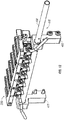
- Some embodiments include an apparatus comprising: a shaft comprising a first end and a second end and a longitudinal axis extending between the first end and the second end; a motor coupled to the shaft, wherein the motor is configured to rotate the shaft about the longitudinal axis of the shaft; a plurality of magnets coupled to the shaft along the longitudinal axis of the shaft, wherein each magnet comprises a first end proximal to the longitudinal axis of the shaft and a second end distal to the longitudinal axis of the shaft; and a module comprising a plurality of housings arranged along a linear axis. The module may comprise, for example, 4 to 24 housings, 4 to 12 housings, 4 to 8 housings, 4 to 6 housings, 6 to 24 housings, or 6 to 12 housings. In specific embodiments, the longitudinal axis of the shaft is substantially parallel to the linear axis of the plurality of housings; and each magnet of the plurality of magnets is aligned with a corresponding housing of the plurality of housings.
- In certain embodiments, the shaft is configured to rotate from a first shaft position in which the second end of each magnet is distal from the corresponding housing; and the shaft is configured to rotate to a second shaft position in which the second end of each magnet is proximal from the corresponding housing. Particular embodiments further comprise: a chamber disposed within each housing of the plurality of housings; and a moveable magnetically responsive component disposed within each chamber. In some embodiments, the second end of each magnet is distal to a side surface of the chamber when the shaft is in the first position; and the second end of each magnet is proximal to a side surface of the chamber and distal to the bottom surface of the chamber when the shaft is in the second position. In specific embodiments, the moveable magnetically responsive component in each chamber is in a first position in contact with a bottom surface of the chamber when the shaft is in the first shaft position; and the moveable magnetically responsive component in each chamber is in a second position in contact with a side surface of the chamber and not in contact with a bottom surface of the chamber when the shaft is in the second shaft position.
- In certain embodiments, the side surface of each chamber is tapered and the bottom surface of each chamber is curved. In particular embodiments, the housing comprises a thermoelectric cooler (TEC). In some embodiments, each chamber comprises a composition of stabilized lyophilized biological reagents comprising a lyophilized pellet comprising nucleoside triphosphates (NTPs) and a polymerase enzyme. In particular embodiments, the moveable magnetically responsive component is a stainless steel ball. In certain aspects, the magnetically responsive component may have a diameter or length in its longest dimension of between about 0.5 mm to about 5 mm, or between about 1 mm to about 2 mm. In some embodiments, the moveable magnetically responsive component is a sphere (i.e., ball) with a diameter of approximately 0.159 cm (0.0625 inches). In specific embodiments, each chamber comprises contents suitable for use in a polymerase chain reaction (PCR) nucleic acid amplification process and wherein the moveable magnetically responsive component is passivated to form an oxide layer that is non-reactive with contents of the chamber. In certain embodiments, each chamber comprises reagents suitable for use in polymerase chain reaction (PCR) nucleic acid amplification process. In particular embodiments, each chamber further comprises a liquid.
- In some embodiments, the moveable magnetically responsive component in each chamber is in a first position in contact with a bottom surface of the chamber when the shaft is in the first shaft position; the moveable magnetically responsive component in each chamber is in a second position that contacts a side surface of the chamber when the shaft is in the second shaft position; and the second position of the moveable magnetically responsive component is located between the surface of the liquid and the bottom surface of the chamber. In specific embodiments, the first shaft position is approximately 15, 20, 25, 30, 35, 50, 60, 70, 80, or 90 degrees from the second shaft position. In some embodiments, the first shaft position is between about 15 to 90 degrees, 20 to 50 degrees, or 20 to 30 degrees from the second shaft position.
- Certain embodiments further comprise a switch configured to limit rotation of the shaft between the first shaft position and the second shaft position. In particular embodiments, the switch is an optical switch comprising a disc coupled to the shaft. In some embodiments, the apparatus is coupled to a polymerase chain reaction (PCR) control module configured to control rotation of the shaft between the first shaft position and the second shaft position. In specific embodiments, the PCR control module is configured to control rotation of the shaft from the first shaft position to the second shaft position such that the moveable magnetically responsive component is held in the first position for approximately 0, 1, 2, 3, 4, 5 seconds (or any range therein) and then moved to the second position and held in the second position for approximately 0, 1, 2, 3, 4, 5 seconds (or any range therein). In certain embodiments, the PCR control module is configured to control rotation of the shaft from the first shaft position to the second shaft position such that the moveable magnetically responsive component is cycled between the first and second positions for approximately 15, 30, 60, 90, 120, 180, 240 or 360 seconds (or any range therein). In some embodiments, the PCR control module is configured to control rotation of the shaft from the first shaft position to the second shaft position such that the moveable magnetically responsive component is cycled between the first and second positions prior to concurrent with the start of the PCR (e.g., during an initial denaturation step or during a reverse transcription phase if it is an RT-PCR), intermittently during the PCR (e.g., mixing during temperature changes to reduce thermal gradients in the reaction), or continuously during all or a substantial portion of the PCR.
- Other embodiments include methods of mixing reagents using an apparatus as disclosed herein. The method may comprise, for example: obtaining an apparatus comprising: a chamber containing a magnetically responsive component and reagents; and a magnet coupled to a rotating shaft, where: the shaft is configured to move from a first shaft position to a second shaft position; in the first shaft position, the second end of the magnet is distal from the chamber; and in the second shaft position, the second end of the magnet is proximal to the chamber; and moving the shaft from a first position to a second position, wherein the magnetically responsive component is moved within the chamber from a first position to a second position, thereby mixing the reagents. The reagents may be, for example, PCR reagents and/or reverse transcription reagents. In some embodiments, the reagents may comprise an enzyme. In certain embodiments, the enzyme may be a polymerase, an endonuclease, or an exonuclease. Certain embodiments include a method of mixing reagents during a polymerase chain reaction (PCR). In specific embodiments the method includes obtaining an apparatus comprising: a chamber containing a magnetically responsive component and reagents, wherein the reagents are suitable for PCR; and a magnet configured to move the magnetically responsive component between a first position in the chamber and a second position in the chamber (e.g. between a bottom surface of the chamber and a side surface of the chamber. Particular embodiments can include a magnet coupled to a rotating shaft, where the shaft is configured to move from a first shaft position to a second shaft position, and in the first shaft position, the second end of the magnet is distal from the chamber, and in the second shaft position, the second end of the magnet is proximal to the chamber. In certain embodiments, the method includes moving the shaft from a first position to a second position, wherein the magnetically responsive component is moved within the chamber from a first position to a second position, thereby mixing the reagents.
- In particular embodiments, the chamber comprises a bottom surface and a side surface, and wherein the magnetically responsive component contacts the bottom surface in the first position and wherein the magnetically responsive component contacts the side surface in the second position. In some embodiments, the magnetically responsive component is moved from the first position to the second position and held in the second position for approximately 0, 1, 2, 3, 4, 5 seconds (or any range therein); and the magnetically responsive component is moved from the second position to the first position and held in the first position for approximately 0, 1, 2, 3, 4, 5 seconds (or any range therein). In specific embodiments, the magnetically responsive component is cycled between the first and second positions for approximately 15, 30, 60, 90, 120, 180, 240 or 360 seconds (or any range therein). In certain embodiments, the moveable magnetically responsive component is cycled between the first and second positions prior to or concurrent with the start of the PCR (e.g., during an initial denaturation step or during a reverse transcription phase if it is an RT-PCR), intermittently during the PCR (e.g., mixing during temperature changes to reduce thermal gradients in the reaction), or continuously during all or a substantial portion of the PCR. In particular embodiments, at least one of the reagents is provided in a lyophilized form. In some embodiments, the side surface of the chamber is tapered and the bottom surface of the chamber is curved. In specific embodiments of the method, the bottom surface is curved with a first radius; the moveable magnetically responsive component is a spherical ball with a second radius; and the first radius is greater than the second radius. Certain embodiments of the method comprise moving the magnetically responsive component prior to beginning a first PCR cycle. Particular embodiments comprise moving the magnetically responsive component during at least a portion of each PCR cycle.
- In some embodiments, the movement of the magnetically responsive component occurs during a temperature ramping phase. In specific embodiments, movement of the magnetically responsive component from the first position to the second position reduces a temperature gradient in the chamber. Certain embodiments comprise moving the magnetically responsive component prior to and during a polymerase chain reaction. Particular embodiments comprise moving the magnetically responsive component prior to beginning a reverse transcription reaction. Some embodiments comprise moving the magnetically responsive component during at least a portion of a reverse transcription reaction. Specific embodiments comprise moving the magnetically responsive component prior to and during a polymerase chain reaction.
- In certain embodiments, movement of the magnetically responsive component from the first position to the second position inverts a melted wax layer in the chamber. In particular embodiments of the methods, the magnetically responsive component is a sphere. In some embodiments of the method, the sphere has a diameter of approximately 0.159 cm (0.0625 inches). In specific embodiments of the method, the magnetically responsive component is a disk or a sphere having a first diameter, and wherein a distance from first position to the second position of the magnetically responsive component is between two and five times the first diameter. In certain embodiments, the reagents are polymerase chain reaction (PCR) reagent. In particular embodiments, the reagents are reverse transcription reagents. In some embodiments, the reagents comprise an enzyme, and in specific embodiments, the enzyme is a polymerase, endonuclease, or a exonuclease.
- Certain embodiments include an apparatus comprising: a housing; an insert disposed within the housing, wherein the insert is configured to receive a chamber; a first electromagnet proximal to a first location on the insert; and a second electromagnet proximal to a second location on the insert. In particular embodiments, the first and second electromagnets are configured to alternatingly and respectively apply a magnetic force to the first and second locations on the insert. In some embodiments, the insert comprises a conical space defined by a tapered side surface having a first end and a second end; the first end is larger in diameter than the second end; the first end is open and the second end is closed; the first location on the insert is located between the first end and the second end of the insert; and the second location is located proximal to the second end of the insert.
- Some embodiments further comprise: a chamber received within the insert; and a moveable magnetically responsive component disposed within the chamber. In specific embodiments, the moveable magnetically responsive component is in a first position when the first electromagnet is activated to apply a magnetic force; and the moveable magnetically responsive component is in a second position when the second electromagnet is activated to apply a magnetic force. In certain embodiments, the chamber comprises contents suitable for use in a polymerase chain reaction (PCR) nucleic acid amplification process and the moveable magnetically responsive component is passivated to form an oxide layer that is non-reactive with contents of the chamber. In particular embodiments, the chamber comprises reagents suitable for use in polymerase chain reaction (PCR) nucleic acid amplification process.
- Certain embodiments include an apparatus comprising: a housing; an insert disposed within the housing, wherein the insert is configured to receive a chamber; and an electromagnet proximal to a first location on the insert, where the electromagnet is configured to alternatingly apply a magnetic force to the location on the insert. In specific embodiments, the insert comprises a conical space defined by a tapered side surface having a first end and a second end; the first end is larger in diameter than the second end; the first end is open and the second end is closed; and the first location on the insert is located between the first end and the second end of the insert.
- Certain embodiments further comprise: a chamber received within the insert; and a moveable magnetically responsive component disposed within the chamber. In particular embodiments, the moveable magnetically responsive component is in a first position when the electromagnet is energized to apply a magnetic force; and the moveable magnetically responsive component is in a second position when the electromagnet is not energized to apply a magnetic force. In certain embodiments, the chamber comprises contents suitable for use in a polymerase chain reaction (PCR) nucleic acid amplification process and the moveable magnetically responsive component is passivated to form an oxide layer that is non-reactive with contents of the chamber. In particular embodiments, the chamber comprises reagents suitable for use in polymerase chain reaction (PCR) nucleic acid amplification process.
- The term "coupled" is defined as connected, although not necessarily directly, and not necessarily mechanically. Two items are "coupleable" if they can be coupled to each other, and, when coupled, may still be characterized as "coupleable." Unless the context explicitly requires otherwise, items that are coupleable are also decoupleable, and vice-versa. One non-limiting way in which a first structure is coupleable to a second structure is for the first structure to be configured to be coupled (or configured to be coupleable) to the second structure.
- The terms "a" and "an" are defined as one or more unless this disclosure explicitly requires otherwise.
- The term "substantially" and its variations (e.g., "approximately" and "about") are defined as being largely but not necessarily wholly what is specified (and include wholly what is specified) as understood by one of ordinary skill in the art. In any disclosed embodiment, the terms "substantially," "approximately," and "about" may be substituted with "within [a percentage] of' what is specified, where the percentage includes .1, 1, 5, and 10 percent.
- The terms "comprise" (and any form of comprise, such as "comprises" and "comprising"), "have" (and any form of have, such as "has" and "having"), "include" (and any form of include, such as "includes" and "including") and "contain" (and any form of contain, such as "contains" and "containing") are open-ended linking verbs. As a result, a method or device that "comprises," "has," "includes" or "contains" one or more steps or elements possesses those one or more steps or elements, but is not limited to possessing only those one or more elements. Likewise, a step of a method or an element of a device that "comprises," "has," "includes" or "contains" one or more features possesses those one or more features, but is not limited to possessing only those one or more features. For example, a system that comprises an ultrasonic transducer has one sample reservoir unit, but may have more than one ultrasonic transducer.
- Furthermore, a device or structure that is configured in a certain way is configured in at least that way, but may also be configured in ways that are not listed. Metric units may be derived from the English units provided by applying a conversion and rounding to the nearest millimeter.
- The feature or features of one embodiment may be applied to other embodiments, even though not described or illustrated, unless expressly prohibited by this disclosure or the nature of the embodiments.
- Any embodiment of any of the disclosed devices and methods can consist of or consist essentially of-rather than comprise/include/contain/have-any of the described elements and/or features and/or steps. Thus, in any of the claims, the term "consisting of' or "consisting essentially of' can be substituted for any of the open-ended linking verbs recited above, in order to change the scope of a given claim from what it would otherwise be using the open-ended linking verb.
- Other features and associated advantages will become apparent with reference to the following detailed description of specific embodiments in connection with the accompanying drawings.
- The following drawings illustrate by way of example and not limitation. For the sake of brevity and clarity, every feature of a given structure may not be labeled in every figure in which that structure appears. Identical reference numbers do not necessarily indicate an identical structure. Rather, the same reference number may be used to indicate a similar feature or a feature with similar functionality, as may non-identical reference numbers.
-
FIG. 1 is perspective view of a polymerase chain reaction (PCR) modular assembly comprising a magnetic actuation assembly and thermo-electric cooler (TEC) sub-assembly according to exemplary embodiments of the present disclosure. -
FIG. 2 is a perspective view of the magnetic actuation assembly of the embodiment ofFIG. 1 . -
FIG. 3 is a perspective view of the (TEC) sub-assembly of the embodiment ofFIG. 1 . -
FIG. 4 is a first perspective view of the magnetic actuation assembly and the (TEC) sub-assembly of the embodiment ofFIG. 1 . -
FIG. 5 is a second perspective view of a partial magnetic actuation assembly and the (TEC) sub-assembly of the embodiment ofFIG. 1 . -
FIG. 6 is a third perspective view of a partial magnetic actuation assembly and the (TEC) sub-assembly of the embodiment ofFIG. 1 . -
FIG. 7 is a partial section view of the magnetic actuation assembly and the (TEC) sub-assembly of the embodiment ofFIG. 1 in a first position. -
FIG. 8 is a partial section view of the magnetic actuation assembly and the (TEC) sub-assembly of the embodiment ofFIG. 1 in a second position. -
FIG. 9 is a partial perspective view of the magnetic actuation assembly and the (TEC) sub-assembly of the embodiment ofFIG. 1 in a first position. -
FIG. 10 is a partial perspective view of the magnetic actuation assembly and the (TEC) sub-assembly of the embodiment ofFIG. 1 in a second position. -
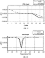
FIG. 11 is a graph of relative fluorescence units (RFU) detected during PCR plotted against PCR cycles performed by the embodiment ofFIG. 1 . -
FIG. 12 is a graph of the delta relative fluorescence units (RFU) detected during melt plotted against temperature performed by the embodiment ofFIG. 1 . -
FIG. 13 is a perspective view of a partial magnetic actuation assembly and a (TEC) sub-assembly. -
FIG. 14 is a partial section view of the embodiment ofFIG. 13 . -
FIG. 15 is a partial section view of a PCR modular assembly comprising electromagnets. -
FIG. 16 is a partial section view of a PCR modular assembly comprising a single electromagnet. - Various features and advantageous details are explained more fully with reference to the non-limiting embodiments that are illustrated in the accompanying drawings and detailed in the following description. It should be understood, however, that the detailed description and the specific examples, while indicating embodiments of the invention, are given by way of illustration only, and not by way of limitation. Various substitutions, modifications, additions, and/or rearrangements will become apparent to those of ordinary skill in the art from this disclosure.
- In the following description, numerous specific details are provided to provide a thorough understanding of the disclosed embodiments. One of ordinary skill in the relevant art will recognize, however, that the invention may be practiced without one or more of the specific details, or with other methods, components, materials, and so forth. In other instances, well-known structures, materials, or operations are not shown or described in detail to avoid obscuring aspects of the invention. It is understood that for purposes of clarity, not all reference numbers are shown for every component visible in each figure.
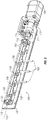
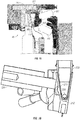
- Referring initially to
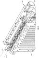
FIGS. 1-6 , a polymerase chain reaction (PCR)modular assembly 50 configured for nucleic acid amplification comprises amagnetic actuation assembly 100 coupled to a thermo-electric cooler (TEC)sub-assembly 200. In the embodiment shown, (PCR)modular assembly 50 also comprises aPCR control module 60 configured to controlmagnetic actuation assembly 100, including for example, the movement or rotation of ashaft 110 ofmagnetic actuation assembly 100. - Referring particularly now to
FIGS. 2-6 ,magnetic actuation assembly 100 comprisesshaft 110 coupled to anelectric motor 120 via a coupling 125 (e.g., a bellows coupling). In the embodiment shown,magnetic actuation assembly 100 also comprises asupport plate 130 andsupport members 135 that supportshaft 110. In particular embodiments,support members 135 can be configured as pillow blocks containing plastic bushings.Magnetic actuation assembly 100 may also comprise one ormore switches 115 that can limit rotation ofshaft 110, as explained in further detail below. - In the embodiment shown,
shaft 110 comprises afirst end 111 and asecond end 112 with alongitudinal axis 113 extending between the first and second end. The embodiment shown also comprises a plurality ofmagnets 150 coupled toshaft 110 alonglongitudinal axis 113. -
Magnetic actuation assembly 100 also comprises a plurality ofretention members 160 configured to retain other components (e.g. fiber-optic cables 161) from interfering with operation ofmagnetic actuation assembly 100. As shown inFIGS. 4 and5 ,TEC sub-assembly 200 can also comprise aheating module 201 and aheat sink 202. - As shown in
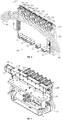
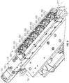
FIGS. 3 and6 ,TEC sub-assembly 200 comprises a plurality ofinserts 250 each disposed within ahousing 205. In exemplary embodiments, inserts 250 can be configured as aluminum TEC blocks configured to conduct thermal energy to a chamber 230 (e.g. a PCR tube) as shown inFIGS. 7 and 8 .Housing 205 may be configured as a TEC block insulator in exemplary embodiments. - As shown in
FIGS. 7 and 8 , aninsert 250 can be configured to receive achamber 230. In particular embodiments, insert 250 comprises aconical space 210 configured to receivechamber 230. In the embodiment shown,conical space 210 ofinsert 250 is defined by a taperedside surface 270 having afirst end 271 that is larger and open, and asecond end 272 that is smaller and closed. In the embodiment shown, the plurality ofhousings 205 are arranged along alinear axis 217 that is substantially parallel tolongitudinal axis 113 of shaft 110 (shown inFIG. 5 ). In the illustrated embodiment eachmagnet 150 is aligned with acorresponding housing 205. - In particular embodiments, each
chamber 230 comprises aside surface 211 that is tapered and abottom surface 212 that is curved, such thatside surface 211 andbottom surface 212 form a generally conical structure. It is understood that the terms "side surface" and "bottom surface" used throughout this disclosure are used only for reference purposes with respect to the drawings. For example,bottom surface 212 does not necessarily have to be at an absolute lowest portion ofchamber 230, depending on the orientation ofchamber 230. During operation,chambers 230 may comprise many different components used for PCR nucleic acid amplification. Forexample chambers 230 may comprise reagents including buffers, nucleotides, modified nucleotides, primers, probes, enzymes, sugars, and stabilizers. - In certain instances, it can be desirable to ensure the reagents are sufficiently mixed together to promote efficiency and accuracy in the PCR process. However, mixing of the components can also create undesirable effects. For example, mixing can create bubbles that interfere with the optical detection by fiber-
optic cables 161. In addition, certain PCR processes can include an insulating layer 213 (e.g. an oil or wax layer) on top of thereagents 214 to reduce evaporation. In specific embodiments, insulatinglayer 213 may comprise 25 µL of docosane wax or mineral oil. If the mixing process is not properly controlled, insulatinglayer 213 can become emulsified withreagents 214, thereby increasing evaporation and reducing accuracy in the PCR detection and analysis. - Embodiments of the present disclosure provide for mixing of the PCR reagents in a controlled manner that reduces the likelihood of unwanted bubble formation or emulsification of insulating
layer 213 andreagents 214. Particular embodiments comprise a moveable magneticallyresponsive component 220 disposed within achamber 230. In certain embodiments, moveable magneticallyresponsive component 220 may be configured as a magnetic 400 series stainless steel (e.g. 440C grade) ball that is passivated to form a non-reactive oxide layer. In specific embodiments, moveable magneticallyresponsive component 220 may be sized in relation to the dimensions ofbottom surface 212 ofchamber 230. For example, moveable magneticallyresponsive component 220 can be a magnetic ball sized to engage the lowest portion of bottom surface 212 (e.g. the portion distal from insulating layer 213) without simultaneously engaging taperedside surface 211. In particular, moveable magneticallyresponsive component 220 can be a spherical or ball shape with a radius R1 that is less than a radius R2 ofbottom surface 212. This can allow moveable magneticallyresponsive component 220 to adequately engage and mix the contents throughoutchamber 230 without trapping bubbles between moveable magneticallyresponsive component 220 andbottom surface 212. In specific embodiments, moveable magneticallyresponsive component 220 can be configured as a spherical ball having a 0.159 cm (1/16 (0.0625) inch) diameter (i.e. a 1/32 or 0.03125 inch radius). - Referring now to
FIGS. 7-10 ,magnetic actuation assembly 100 can be actuated such thatshaft 110 is moved (e.g. rotated) from afirst shaft position 117 to asecond shaft position 119. As shown inFIGS. 7 and 8 ,magnet 150 is coupled toshaft 110 via acoupler 155 thatspaces magnet 150 away fromaxis 113 ofshaft 110. In this embodiment, eachmagnet 150 comprises afirst end 151 proximal tolongitudinal axis 113 and asecond end 152 distal tolongitudinal axis 113. Such a configuration allowssecond end 152 to swing in a wider rotational arc thanfirst end 151 asshaft 110 is rotated. - In the embodiment shown, switch 115 (shown in
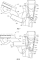
FIG. 2 ) can limit rotation ofshaft 110 betweenfirst shaft position 117 andsecond shaft position 119. In particular embodiments, switch 115 may be configured as an optical switch that limits rotation ofshaft 110 to approximately 25 degrees between the first shaft position and the second shaft position. In specific embodiments, switch 115 may comprise a disc 116 that breaks an optical path withinswitch 115 to control rotation ofshaft 110. - In first shaft position 117 (shown in
FIGS. 7 and9 )second end 152 ofmagnet 150 is distal fromchamber 230. In the first position, moveable magneticallyresponsive component 220 also contactsbottom surface 212 ofchamber 230. In particular embodiments,magnet 150 may be an axially-magnetized magnet. Such a configuration can allowmagnet 150 to exert a magnetic force on moveable magneticallyresponsive component 220 towardsbottom surface 212 whenshaft 110 is in the first position. This can help overcome viscosity drag forces between moveable magneticallyresponsive component 220 andreagents 214 and assist moveable magneticallyresponsive component 220 to contactbottom surface 212. In certain cases, the force of gravity alone may not be sufficient to overcome the viscous forces to ensure contact between moveable magneticallyresponsive component 220 andbottom surface 212. - In
second shaft position 119 of shaft 110 (shown inFIGS. 8 and10 ),second end 152 ofmagnet 150 is proximal tochamber 230 and moveable magneticallyresponsive component 220contacts side surface 211 ofchamber 230 as a result of the magnetic force exerted bymagnet 150. As shown inFIG. 8 , insecond shaft position 119, moveable magneticallyresponsive component 220 is located below an interface 215 of insulatinglayer 213 and reagents 214 (e.g. between interface 215 and bottom surface 212). The relocation of moveable magneticallyresponsive component 220 between the first position contactingbottom surface 212 and the second position contactingside surface 211 can promote mixing of the contents ofchamber 230. - As shown in
FIGS. 3 ,9 and 10 , eachhousing 205 may include a slot or opening 206 facing amagnet 150. In the first position shown inFIG. 9 ,magnet 150 is proximal to the lower portion of opening 206, and in the second position shown inFIG. 10 ,magnet 150 extends into opening 206 and is proximal to the upper end of opening 206. Opening 206 is configured to receivemagnet 150 such thatsecond end 152 ofmagnet 150 extends into opening 206 whenshaft 110 is insecond shaft position 119. - In certain embodiments,
housing 205 may function as an insulator or heat block to retain thermal energy inchamber 230 provided byheating module 201. In addition,housing 205 may comprise openings 207 for receiving and coupling fiber-optic cables 161. Furthermore,housing 205 may comprise an opening 208 for receivingchamber 230 and tapered wall 221 (defining a generally conical shape) configured to engageside surface 270 ofchamber 230. - In particular embodiments, moveable magnetically
responsive component 220 can be held in the second position for approximately 3 seconds, and then moved back to the first position for approximately 3 seconds to mix the contents ofchamber 230. In certain embodiments, this cycling of moveable magneticallyresponsive component 220 between the first and second positions can be repeated for approximately 90 seconds. In particular embodiments, the rotation ofshaft 110 between the first shaft position and the second shaft position can be controlled byPCR control module 60 of PCRmodular assembly 50. - In specific embodiments,
chamber 230 may comprise biological reagents that are inherently unstable at ambient temperatures and are stabilized with sugars via lyophilization. Lyophilization of biological reagents results in generation of material with low moisture content (e.g., less than 5 percent) and the functionality of the lyophilized material is compromised if it is not stored dry. Continued stability of lyophilized material therefore requires methods to prevent moisture absorption which includes secondary containers, storage in dry humidity environment, etc. In certain examples, a layer of wax can be used to create a moisture barrier for the lyophilized material that improves the stability of lyophilized reagents. - In certain embodiments, lyophilized material can be stabilized with insulating
layer 213, which allows for storage of sample extraction cassette at ambient conditions without special requirements for a low humidity environment. As previously mentioned, insulatinglayer 213 can also used as a vapor barrier during PCR to reduce or prevent evaporation. After PCR cycling, insulating layer 213 (e.g. wax) can also solidify and create a full or partial barrier to potential amplicon contamination. An amplicon can be difficult to eliminate if it contaminates a lab and the solid wax significantly reduces the chance of such an occurrence. - The mixing process described herein can assist in the inversion of insulating
layer 213 that has not naturally inverted by disrupting the surface tension at the insulating layer-resuspension buffer interface. Moveable magneticallyresponsive component 220 can also disrupt the surface tension, allowing for air bubbles that may be caught in the resuspension buffer to be released and rise to the top. Furthermore, the magnetic mixing process described herein can be used to mix the resuspension buffer with the lyophilized cake and promote uniform distribution of components, as well as reduce a temperature gradient withinchamber 230. - Examples of the benefits of mixing contents of
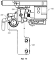
chamber 230 can be illustrated inFIGS. 11 and 12 . InFIG. 11 , the relative fluorescence units (RFU) detected during PCR are plotted against PCR cycles.FIG. 12 illustrates the delta in RFU plotted against temperature in a derivative melt curve. InFIGS. 11 and 12 the lighter / dotted line illustrates results from of contents that are not mixed in the PCR chamber, while the darker (non-dotted) lines illustrated results from contents that are mixed.FIG. 11 shows that the non-mixed results did not reach the desired baseline RFU value until approximately 18-20 cycles had been performed and there was a delay in shoulder between mixed and non-mixed.FIG. 12 shows the delta RFU is substantially reduced in the non-mixed results as compared to those of the mixed results. - Other exemplary embodiments may utilize different components or configurations from those disclosed above. For example, certain exemplary embodiments may comprise a rotating magnetic rod rather than a plurality of magnets coupled to a rotating rod. Referring now to
FIGS. 13-14 ,TEC 200 is coupled to amagnetic actuation assembly 400 that comprises a rotatingmagnetic rod 450 supported bybrackets FIG. 14 ,magnetic rod 450 is radially magnetized such that the north pole (N) of the magnetic field extends from location on the circumference of the rod and the south pole (S) of the magnetic field extends from a location approximately 180 degrees circumferentially from the north pole. Accordingly, asmagnetic rod 450 rotates along axis 413, the north and south poles N and S will be directed towardinsert 250 and a PCR chamber (not shown) inserted intoinsert 250. Similar to previously described embodiments, the alternating magnetic field can direct movement of a moveable magnetically responsive component contained within a PCR chamber disposed withininsert 250. Such movement can be used for multiple purposes, including for example, mixing components or reducing a temperature gradient. - In addition to the previously described embodiments, certain embodiments may utilize electromagnets to apply a magnetic force to the contents of a PCR chamber, including a moveable magnetically responsive component. Referring now to
FIG. 15 , a polymerase chain reaction (PCR)modular assembly 40 configured for nucleic acid amplification comprises afirst electromagnet 351 and asecond electromagnet 352. Similar to previous embodiments, this embodiment also compriseshousing 205 and insert 250. For purposes of clarity, not all features ofinsert 250 are labeled inFIG. 15 , but it is understood thatinsert 250 inFIG. 15 comprises features equivalent to those shown inFIGS. 7 and 8 (including for example, taperedside surface 270 havingfirst end 271 that is larger and open, andsecond end 272 that is smaller and closed.) - In this embodiment,
first electromagnet 351 is proximal to afirst location 261 oninsert 250 that is located betweenfirst end 271 andsecond end 272.Second electromagnet 352 is proximal to asecond location 262 that is proximal tosecond end 272 ofinsert 250. First andsecond electromagnets second locations insert 250. For example,first electromagnet 351 can be energized to apply a magnetic force tofirst location 261 whilesecond electromagnet 352 is not energized to exert a magnetic force. Subsequently,second electromagnet 352 can be energized to apply a magnetic force tosecond location 352 whilefirst electromagnet 352 is not energized to apply a magnetic force. This pattern can be repeated such that magnetic forces are alternatingly applied to first andsecond locations - Accordingly, as first and
second electromagnets second locations insert 250 and a PCR chamber (not shown) inserted intoinsert 250. Similar to previously described embodiments, the alternating magnetic field can direct movement of a moveable magnetically responsive component contained within a PCR chamber disposed withininsert 250. Such movement can be used for multiple purposes, including for example, to mix components or reduce a temperature within the insert or a chamber disposed within the insert. - Referring now to
FIG. 16 , another exemplary embodiment comprises asingle electromagnet 551. This embodiment is similar to the embodiment described inFIG. 15 , but allows the force of gravity to direct magneticallyresponsive component 220 tobottom surface 212 of chamber 230 (instead of a magnetic force applied by a second electromagnet). In this embodiment,electromagnet 551 can be energized to apply a magnetic force and direct magneticallyresponsive component 220 toside surface 211 ofchamber 230.Electromagnet 551 can then be de-energized to reduce or eliminate the magnetic force applied to magneticallyresponsive component 220, allowing magneticallyresponsive component 220 to fall tobottom surface 212 ofchamber 230.Electromagnet 551 can be alternatingly energized and de-energized to move the ball from a first location (e.g. side surface 211) to a second location (e.g. bottom surface 212). Such movement can be used, for example, to mix components or reduce a temperature within the insert or a chamber disposed within the insert. - Still other embodiments may comprise a different configuration of electromagnets. For example, certain embodiments may comprise two electromagnets at the same level, but wired in opposite polarity so that the magnetic flux jumps the gap between the electromagnets (similar to the spark in a spark plug). Other embodiments may comprise electromagnets that alternate polarity along an array of adjacent PCR chambers, for the effect of concentrating flux in the zone of the PCR chamber. Certain embodiments may comprise electromagnets with various back iron configurations to control the shape of the magnetic flux field.
- It should be understood that the present devices and methods are not intended to be limited to the particular forms disclosed. Rather, they are to cover all modifications, equivalents, and alternatives falling within the scope of the claims. For example, in certain embodiments different configurations of magnets and or moveable magnetically responsive components may be used. In addition, other embodiments may use different time periods for holding shaft and moveable magnetically responsive components in the different positions.
- The above specification and examples provide a complete description of the structure and use of an exemplary embodiment. Although certain embodiments have been described above with a certain degree of particularity, or with reference to one or more individual embodiments, those skilled in the art could make numerous alterations to the disclosed embodiments without departing from the scope of this invention. As such, the illustrative embodiment of the present devices is not intended to be limited to the particular forms disclosed. Rather, they include all modifications and alternatives falling within the scope of the claims, and embodiments other than the one shown may include some or all of the features of the depicted embodiment. Further, where appropriate, aspects of any of the examples described above may be combined with aspects of any of the other examples described to form further examples having comparable or different properties and addressing the same or different problems. Similarly, it will be understood that the benefits and advantages described above may relate to one embodiment or may relate to several embodiments.
- The claims are not to be interpreted as including means-plus- or step-plus-function limitations, unless such a limitation is explicitly recited in a given claim using the phrase(s) "means for" or "step for," respectively.
- Below, aspects of the invention are summarized in clauses. Any information provided by these clauses forms a part of the disclosure of the present application and may be included in the claims and/or may be the subject of potential divisional applications. This paragraph and the following clauses may be cancelled when preparing the text in which the EPO intends to grant the patent as defined by R. 71(3) EPC.
-
- Clause 1. An apparatus comprising:
- a shaft comprising a first end and a second end and a longitudinal axis extending between the first end and the second end;
- a motor coupled to the shaft, wherein the motor is configured to rotate the shaft about the longitudinal axis of the shaft;
- a magnet coupled to the shaft, wherein the magnet comprises a first end proximal to the longitudinal axis of the shaft and a second end distal to the longitudinal axis of the shaft; and
- a housing configured to receive a chamber, wherein:
- the shaft is configured to move from a first shaft position to a second shaft position;
- in the first shaft position, the second end of the magnet is distal from the housing; and
- in the second shaft position, the second end of the magnet is proximal to the housing.
- Clause 2: The apparatus of clause 1 wherein the shaft is configured to rotate from the first shaft position to the second shaft position.
- Clause 3: The apparatus of clause 1 wherein the housing comprises an insert configured to receive the chamber.
- Clause 4: The apparatus of clause 1 further comprising:
- a chamber received within the housing; and
- a moveable magnetically responsive component disposed within the chamber, wherein:
- the moveable magnetically responsive component is in a first position when the shaft is in the first shaft position; and
- the moveable magnetically responsive component is in a second position when the shaft is in the second shaft position.
- Clause 5: The apparatus of clause 4 wherein:
- the moveable magnetically responsive component is in contact with the bottom surface of the chamber when the moveable magnetically responsive component is in the first position; and
- the moveable magnetically responsive component is in contact with the side surface of the chamber when the moveable magnetically responsive component is in the second position.
- Clause 6: The apparatus of clause 4 wherein the housing comprises a thermoelectric cooler (TEC).
- Clause 7: The apparatus of clause 4 wherein the chamber comprises a composition of stabilized lyophilized biological reagents.
- Clause 8: The apparatus of clause 4 wherein the side surface of the chamber is tapered and the bottom surface of the chamber is curved.
- Clause 9: The apparatus of clause 8 wherein:
- the bottom surface is curved with a first radius;
- the moveable magnetically responsive component is a spherical ball with a second radius; and
- the first radius is greater than the second radius.
- Clause 10: The apparatus of clause 4 wherein the moveable magnetically responsive component is a disk.
- Clause 11: The apparatus of clause 4 wherein the moveable magnetically responsive component is a rod.
- Clause 12: The apparatus of clause 11 wherein the rod has a length between approximately 0.0625 inches and 0.125 inches.
- Clause 13: The apparatus of clause 4 wherein the moveable magnetically responsive component is a magnetic 400 series stainless steel ball.
- Clause 14: The apparatus of clause 13 wherein the chamber comprises contents suitable for use in a polymerase chain reaction (PCR) nucleic acid amplification process and wherein the moveable magnetically responsive component is passivated to form an oxide layer that is non-reactive with contents of the chamber.
- Clause 15: The apparatus of clause 4 wherein the chamber comprises reagents suitable for use in polymerase chain reaction (PCR) nucleic acid amplification process.
- Clause 16: The apparatus of clause 1 wherein the first shaft position is approximately 25 degrees from the second shaft position.
- Clause 17: The apparatus of clause 1 further comprising a switch configured to limit rotation of the shaft between the first shaft position and the second shaft position.
- Clause 18: The apparatus of clause 17 wherein the switch is an optical switch comprising a disc coupled to the shaft.
- Clause 19: The apparatus of clause 1, wherein the apparatus is coupled to a polymerase chain reaction (PCR) control module configured to control rotation of the shaft between the first shaft position and the second shaft position.
- Clause 20: The apparatus of clause 19 wherein the PCR control module is configured to control rotation of the shaft from the first shaft position to the second shaft position such that the moveable magnetically responsive component is held in the first position for approximately 3 seconds and then moved to the second position and held in the second position for approximately 3 seconds.
- Clause 21: The apparatus of
clause 20 wherein the PCR control module is configured to control rotation of the shaft from the first shaft position to the second shaft position such that the moveable magnetically responsive component is cycled between the first and second positions for approximately 90 seconds. - Clause 22: The apparatus of clause 1 wherein the magnet has a maximum energy product (BHmax) of approximately 52 Megagauss-Oersteds (MGOe).
- Clause 23: The apparatus of clause 1 wherein the second end of the magnet is located approximately 0.82 inches from the longitudinal axis of the rotating shaft.
- Clause 24: The apparatus of clause 1 wherein the second end of the magnet is approximately 0.21 inches from a centroid of the moveable magnetically responsive component when the system is in the first shaft position.
- Clause 25: The apparatus of clause 1 wherein the magnet is longitudinally magnetized.
- Clause 26: The apparatus of clause 1 wherein the magnet is a made of neodymium.
- Clause 27: The apparatus of clause 1 wherein the magnet is cylindrical in shape, with a diameter of approximately 0.125 inches and a length of 0.375 inches.
- Clause 28: The apparatus of clause 1 wherein the housing comprises a first opening configured to receive the magnet such that the second end of the magnet extends into the first opening when the shaft is in the second shaft position.
- Clause 29: The apparatus of clause 1 wherein the housing comprises a second opening configured to receive a chamber.
- Clause 30: The apparatus of clause 1 wherein the housing comprises a third opening configured to receive a fiber-optic cable.
- Clause 31: The apparatus of clause 1 wherein the housing comprises an insert defining a conical space.
- Clause 32: An apparatus comprising:
- a shaft comprising a first end and a second end and a longitudinal axis extending between the first end and the second end;
- a motor coupled to the shaft, wherein the motor is configured to rotate the shaft about the longitudinal axis of the shaft;
- a plurality of magnets coupled to the shaft along the longitudinal axis of the shaft, wherein each magnet comprises a first end proximal to the longitudinal axis of the shaft and a second end distal to the longitudinal axis of the shaft; and
- a module comprising a plurality of housings arranged along a linear axis, wherein:
- the longitudinal axis of the shaft is substantially parallel to the linear axis of the plurality of housings; and
- each magnet of the plurality of magnets is aligned with a corresponding housing of the plurality of housings.
- Clause 33: The apparatus of clause 32, wherein:
- the shaft is configured to rotate from a shaft first position in which the second end of each magnet is distal from the corresponding housing; and
- the shaft is configured to rotate to a second shaft position in which the second end of each magnet is proximal from the corresponding housing.
- Clause 34: The apparatus of clause 32 further comprising:
- a chamber disposed within each housing of the plurality of housings; and
- a moveable magnetically responsive component disposed within each chamber.
- Clause 35: The apparatus of clause 34 wherein:
- the second end of each magnet is distal to a side surface of the chamber when the shaft is in the first position; and
- the second end of each magnet is proximal to a side surface of the chamber and distal to the bottom surface of the chamber when the shaft is in the second position.
- Clause 36: The apparatus of clause 34 wherein:
- the moveable magnetically responsive component in each chamber is in a first position in contact with a bottom surface of the chamber when the shaft is in the first shaft position; and
- the moveable magnetically responsive component in each chamber is in a second position in contact with a side surface of the chamber and not in contact with a bottom surface of the chamber when the shaft is in the second shaft position.
- Clause 37: The apparatus of clause 36 wherein the side surface of each chamber is tapered and the bottom surface of each chamber is curved.
- Clause 38: The apparatus of clause 34 wherein the apparatus is wherein the housing comprises a thermoelectric cooler (TEC).
- Clause 39: The apparatus of clause 34 wherein each chamber comprises a composition of stabilized lyophilized biological reagents comprising a lyophilized pellet comprising nucleoside triphosphates (NTPs) and a polymerase enzyme.
- Clause 40: The apparatus of clause 34 wherein the moveable magnetically responsive component is a magnetic 400 series stainless steel ball.
- Clause 41: The apparatus of clause 34 wherein the moveable magnetically responsive component is a sphere with a diameter of approximately 0.0625 inches.
- Clause 42: The apparatus of clause 34 wherein each chamber comprises contents suitable for use in a polymerase chain reaction (PCR) nucleic acid amplification process and wherein the moveable magnetically responsive component is passivated to form an oxide layer that is non-reactive with contents of the chamber.
- Clause 43: The apparatus of clause 34 wherein each chamber comprises reagents suitable for use in polymerase chain reaction (PCR) nucleic acid amplification process.
- Clause 44: The apparatus of clause 34 wherein each chamber further comprises a liquid.
- Clause 45: The apparatus of clause 44 wherein:
- the moveable magnetically responsive component in each chamber is in a first position in contact with a bottom surface of the chamber when the shaft is in the first shaft position;
- the moveable magnetically responsive component in each chamber is in a second position that contacts a side surface of the chamber when the shaft is in the second shaft position; and
- the second position of the moveable magnetically responsive component is located between the surface of the liquid and the bottom surface of the chamber.
- Clause 46: The apparatus of clause 32 wherein the first shaft position is approximately 25 degrees from the second shaft position.
- Clause The apparatus of clause 32 further comprising a switch configured to limit rotation of the shaft between the first shaft position and the second shaft position.
- Clause 48: The apparatus of clause 47 wherein the switch is an optical switch comprising a disc coupled to the shaft.
- Clause 49: The apparatus of clause 32, wherein the apparatus is coupled to a polymerase chain reaction (PCR) control module configured to control rotation of the shaft between the first shaft position and the second shaft position.
- Clause 50: The apparatus of clause 49 wherein the PCR control module is configured to control rotation of the shaft from the first shaft position to the second shaft position such that the moveable magnetically responsive component is held in the first position for approximately 3 seconds and then moved to the second position and held in the second position for approximately 3 seconds.
- Clause 51: The apparatus of
clause 50 wherein the PCR control module is configured to control rotation of the shaft from the first shaft position to the second shaft position such that the moveable magnetically responsive component is cycled between the first and second positions for approximately 90 seconds. - Clause 52. A method of mixing reagents, the method comprising:
- obtaining an apparatus comprising:
- a chamber containing a magnetically responsive component and reagents; and
- a magnet coupled to a rotating shaft, where:
- the shaft is configured to move from a first shaft position to a second shaft position;
- in the first shaft position, the second end of the magnet is distal from the chamber; and
- in the second shaft position, the second end of the magnet is proximal to the chamber; and
- moving the shaft from a first position to a second position, wherein the magnetically responsive component is moved within the chamber from a first position to a second position, thereby mixing the reagents.
- obtaining an apparatus comprising:
- Clause 53: The method of clause 52 wherein the chamber comprises a bottom surface and a side surface, and wherein the magnetically responsive component contacts the bottom surface in the first position and wherein the magnetically responsive component contacts the side surface in the second position.
- Clause 54: The method of clause 52 wherein:
- the magnetically responsive component is moved from the first position to the second position and held in the second position for approximately 3 seconds; and
- the magnetically responsive component is moved from the second position to the first position and held in the first position for approximately 3 seconds.
- Clause 55: The method of clause 54 wherein the magnetically responsive component is cycled between the first and second positions for approximately 90 seconds.
- Clause 56: The method of clause 52 wherein at least one of the reagents is provided in a lyophilized form.
- Clause 57: The method of clause 52 wherein the side surface of the chamber is tapered and the bottom surface of the chamber is curved.
- Clause 58: The method of clause 57 wherein:
- the bottom surface is curved with a first radius;
- the moveable magnetically responsive component is a spherical ball with a second radius; and
- the first radius is greater than the second radius.
- Clause 59: The method of clause 52, comprising moving the magnetically responsive component prior to beginning a polymerase chain reaction.
- Clause 60: The method of clause 52, comprising moving the magnetically responsive component during at least a portion of a polymerase chain reaction.
- Clause 61: The method of
clause 60, wherein movement of the magnetically responsive component occurs during a temperature ramping phase. - Clause 62: The method of
clause 60, wherein movement of the magnetically responsive component from the first position to the second position reduces a temperature gradient in the chamber. - Clause 63: The method of clause 52, comprising moving the magnetically responsive component prior to and during a polymerase chain reaction.
- Clause 64: The method of clause 52, comprising moving the magnetically responsive component prior to beginning a reverse transcription reaction.
- Clause 65: The method of clause 52, comprising moving the magnetically responsive component during at least a portion of a reverse transcription reaction.
- Clause 66: The method of clause 52, comprising moving the magnetically responsive component prior to and during a polymerase chain reaction.
- Clause 67: The method of clause 52, wherein movement of the magnetically responsive component from the first position to the second position inverts a wax lyophilized layer in the chamber.
- Clause 68: The method of clause 52 wherein the magnetically responsive component is a sphere.
- Clause 69: The method of clause 68 wherein the sphere has a diameter of approximately 0.0625 inches.
- Clause 70: The method of clause 52 wherein the magnetically responsive component is a disk or a sphere having a first diameter, and wherein a distance from first position to the second position of the magnetically responsive component is between two and five times the first diameter.
- Clause 71: The method of clause 52 wherein the reagents are polymerase chain reaction (PCR) reagents.
- Clause 72: The method of clause 52 wherein the reagents are reverse transcription reagents.
- Clause 73: The method of clause 52 wherein the reagents comprise an enzyme.
- Clause 74: The method of clause 73 wherein the enzyme is a polymerase, endonuclease, or a exonuclease.
- Clause 75: An apparatus comprising:
- a housing;
- an insert disposed within the housing, wherein the insert is configured to receive a chamber;
- a first electromagnet proximal to a first location on the insert; and
- a second electromagnet proximal to a second location on the insert, wherein:
the first and second electromagnets are configured to alternatingly and respectively apply a magnetic force to the first and second locations on the insert.
- Clause 76: The apparatus of
clause 75, wherein:- the insert comprises a conical space defined by a tapered side surface having a first end and a second end;
- the first end is larger in diameter than the second end;
- the first end is open and the second end is closed;
- the first location on the insert is located between the first end and the second end of the insert; and
- the second location is located proximal to the second end of the insert.
- Clause 77: The apparatus of
clause 75 further comprising:- a chamber received within the insert; and
- a moveable magnetically responsive component disposed within the chamber, wherein:
- the moveable magnetically responsive component is in a first position when the first electromagnet is activated to apply a magnetic force; and
- the moveable magnetically responsive component is in a second position when the second electromagnet is activated to apply a magnetic force.
- Clause 78: An apparatus comprising:
- a housing;
- an insert disposed within the housing, wherein the insert is configured to receive a chamber; and
- an electromagnet proximal to a first location on the insert, wherein:
the electromagnet is configured to alternatingly apply a magnetic force to the location on the insert.
- Clause 79: The apparatus of clause 78, wherein:
- the insert comprises a conical space defined by a tapered side surface having a first end and a second end;
- the first end is larger in diameter than the second end;
- the first end is open and the second end is closed; and
- the first location on the insert is located between the first end and the second end of the insert.
- Clause 80: The apparatus of clause 78 further comprising:
- a chamber received within the insert; and
- a moveable magnetically responsive component disposed within the chamber, wherein:
- the moveable magnetically responsive component is in a first position when the electromagnet is energized to apply a magnetic force; and
- the moveable magnetically responsive component is in a second position when the electromagnet is not energized to apply a magnetic force.
- The following references are incorporated herein by reference:
Claims (15)
- A method of mixing reagents, the method comprising:obtaining an apparatus comprising:a chamber (230) containing a magnetically responsive component (220) and reagents; anda magnet (150) coupled to a rotating shaft (110), where:the shaft (110) is configured to move from a first shaft position (117) to a second shaft position (119);in the first shaft position (117), the second end of the magnet (150) is distal from the chamber (230); andin the second shaft position (119), the second end of the magnet (150) is proximal to the chamber (230); andmoving the shaft (110) from a first shaft position (117) to a second shaft position (119), wherein the magnetically responsive component (220) is moved within the chamber (230) from a first position to a second position, thereby mixing the reagents.
- The method of claim 1 wherein the chamber (230) comprises a bottom surface (212) and a side surface (211), and wherein the magnetically responsive component contacts the bottom surface in the first position and wherein the magnetically responsive component contacts the side surface in the second position.
- The method of claim 1 wherein:the magnetically responsive component (220) is moved from the first position to the second position and held in the second position for approximately 3 seconds; andthe magnetically responsive component (220) is moved from the second position to the first position and held in the first position for approximately 3 seconds.
- The method of claim 3 wherein the magnetically responsive component (220) is cycled between the first and second positions for approximately 90 seconds.
- The method of claim 1 wherein at least one of the reagents is provided in a lyophilized form.
- The method of claim 1 wherein the side surface (211) of the chamber (230) is tapered and the bottom surface (212) of the chamber (230) is curved.
- The method of claim 6 wherein:the bottom surface (212) is curved with a first radius;the moveable magnetically responsive component (220) is a spherical ball with a second radius; andthe first radius is greater than the second radius.
- The method of claim 1, comprising moving the magnetically responsive component (220)- prior to beginning a polymerase chain reaction, and/or- during at least a portion of a polymerase chain reaction, or
- The method of claim 1, characterized in that it comprises moving the magnetically responsive component (220) during at least a portion of a polymerase chain reaction, wherein- movement of the magnetically responsive component (220) occurs during a temperature ramping phase, or- movement of the magnetically responsive component (220) from the first position to the second position reduces a temperature gradient in the chamber (230).
- The method of claim 1, comprising moving the magnetically responsive component (220)- prior to beginning a reverse transcription reaction, or- during at least a portion of a reverse transcription reaction.
- The method of claim 1, wherein movement of the magnetically responsive
component (220) from the first position to the second position inverts a wax lyophilized layer in the chamber (230). - The method of claim 1 wherein the magnetically responsive component (220) is a sphere.
- The method of claim 12 wherein the sphere has a diameter of approximately 0.159 cm (0.0625 inches).
- The method of claim 1 wherein the magnetically responsive component (220) is a disk or a sphere having a first diameter, and wherein a distance from first position to the second position of the magnetically responsive component (220) is between two and five times the first diameter.
- The method of claim 1 wherein the reagents- are polymerase chain reaction (PCR) reagents or reverse transcription reagents, or- comprise an enzyme, or- comprise an enzyme, wherein the enzyme is a polymerase, endonuclease, or a exonuclease.
Applications Claiming Priority (3)
| Application Number | Priority Date | Filing Date | Title |
|---|---|---|---|
| US201462013648P | 2014-06-18 | 2014-06-18 | |
| PCT/US2015/034332 WO2015195357A1 (en) | 2014-06-18 | 2015-06-05 | Apparatus and methods for magnetic mixing |
| EP15809156.1A EP3157658B1 (en) | 2014-06-18 | 2015-06-05 | Apparatus for magnetic mixing |
Related Parent Applications (2)
| Application Number | Title | Priority Date | Filing Date |
|---|---|---|---|
| EP15809156.1A Division EP3157658B1 (en) | 2014-06-18 | 2015-06-05 | Apparatus for magnetic mixing |
| EP15809156.1A Division-Into EP3157658B1 (en) | 2014-06-18 | 2015-06-05 | Apparatus for magnetic mixing |
Publications (1)
| Publication Number | Publication Date |
|---|---|
| EP3892366A1 true EP3892366A1 (en) | 2021-10-13 |
Family
ID=54869086
Family Applications (2)
| Application Number | Title | Priority Date | Filing Date |
|---|---|---|---|
| EP15809156.1A Active EP3157658B1 (en) | 2014-06-18 | 2015-06-05 | Apparatus for magnetic mixing |
| EP21170510.8A Pending EP3892366A1 (en) | 2014-06-18 | 2015-06-05 | Method for magnetic mixing |
Family Applications Before (1)
| Application Number | Title | Priority Date | Filing Date |
|---|---|---|---|
| EP15809156.1A Active EP3157658B1 (en) | 2014-06-18 | 2015-06-05 | Apparatus for magnetic mixing |
Country Status (8)
| Country | Link |
|---|---|
| US (2) | US10179899B2 (en) |
| EP (2) | EP3157658B1 (en) |
| JP (2) | JP6491240B2 (en) |
| KR (2) | KR102381695B1 (en) |
| CN (2) | CN106488799B (en) |
| AU (1) | AU2015277637B2 (en) |
| CA (1) | CA2951649C (en) |
| WO (1) | WO2015195357A1 (en) |
Families Citing this family (4)
| Publication number | Priority date | Publication date | Assignee | Title |
|---|---|---|---|---|
| AU2015277637B2 (en) | 2014-06-18 | 2019-03-28 | Luminex Corporation | Apparatus and methods for magnetic mixing |
| FR3038526A1 (en) * | 2015-07-06 | 2017-01-13 | Provaine | SYSTEM FOR MANUFACTURING A FORMULATION |
| US10953376B2 (en) * | 2015-09-03 | 2021-03-23 | Tetracore, Inc. | Device and method for mixing and bubble removal |
| KR102092003B1 (en) * | 2019-12-05 | 2020-05-15 | 한창기전 주식회사 | Total phosphorus and total nitrogen measurement system with oxidation pre-treatment unit integral fluid movement system |
Citations (12)
| Publication number | Priority date | Publication date | Assignee | Title |
|---|---|---|---|---|
| FR2109370A5 (en) * | 1970-10-14 | 1972-05-26 | Bernard Du Grail Alain | |
| US4040605A (en) * | 1976-07-14 | 1977-08-09 | Marvin Stanley Towsend | Magnetic stirring apparatus |
| US4911555A (en) | 1989-05-04 | 1990-03-27 | The Jackson Laboratory | Magnetic stirrer for multiple samples |
| US5352036A (en) | 1992-09-23 | 1994-10-04 | Habley Medical Technology Corporation | Method for mixing and dispensing a liquid pharmaceutical with a miscible component |
| US5578201A (en) | 1993-07-30 | 1996-11-26 | E. I. Du Pont De Nemours And Company | Apparatus for mixing liquids used in countercurrent multiphase liquid separation |
| US6176609B1 (en) | 1998-10-13 | 2001-01-23 | V & P Scientific, Inc. | Magnetic tumble stirring method, devices and machines for mixing in vessels |
| US6357907B1 (en) | 1999-06-15 | 2002-03-19 | V & P Scientific, Inc. | Magnetic levitation stirring devices and machines for mixing in vessels |
| US20020154570A1 (en) * | 2001-04-24 | 2002-10-24 | Dade Behring Inc. | Method and apparatus for mixing liquid samples in a container using rotating magnetic fields |
| US6579453B1 (en) * | 1997-09-29 | 2003-06-17 | Roche Diagnostics Corporation | Apparatus for separating magnetic particles |
| US8048375B2 (en) | 2007-06-21 | 2011-11-01 | Gen-Probe Incorporated | Gravity-assisted mixing methods |
| US8550694B2 (en) | 2008-09-16 | 2013-10-08 | Ibis Biosciences, Inc. | Mixing cartridges, mixing stations, and related kits, systems, and methods |
| WO2015195357A1 (en) | 2014-06-18 | 2015-12-23 | Luminex Corporation | Apparatus and methods for magnetic mixing |
Family Cites Families (26)
| Publication number | Priority date | Publication date | Assignee | Title |
|---|---|---|---|---|
| US2774803A (en) | 1952-09-20 | 1956-12-18 | Asea Ab | Inductive stirring device for metallurgical furnace |
| US5306510A (en) * | 1988-01-14 | 1994-04-26 | Cyberlab, Inc. | Automated pipetting system |
| US5599660A (en) | 1993-01-19 | 1997-02-04 | Pharmacia Biotech Inc. | Method and preparation for sequential delivery of wax-embedded, inactivated biological and chemical reagents |
| DE19644302A1 (en) | 1995-11-28 | 1997-06-05 | Boehringer Mannheim Gmbh | Method for the detection of telomerase activity |
| US6086831A (en) * | 1998-06-10 | 2000-07-11 | Mettler-Toledo Bohdan, Inc. | Modular reaction block assembly with thermoelectric cooling and heating |
| US6793167B2 (en) * | 1999-01-12 | 2004-09-21 | Island Oasis Cocktail Company, Inc. | Food processing apparatus including magnetic drive |
| WO2001001136A1 (en) | 1999-06-30 | 2001-01-04 | Quidel Corporation | Method and kit for measuring total pyridinium crosslinks |
| WO2001011336A1 (en) * | 1999-08-05 | 2001-02-15 | Harrison, Bruce Trading As Sxy Tech | Direct aspiration-reaction and injection device and methods of use |
| US6382827B1 (en) * | 2000-11-01 | 2002-05-07 | Dade Behring Inc. | Method and apparatus for mixing liquid solutions using a rotating magnet to generate a stirring vortex action |
| JP2002152308A (en) * | 2000-11-09 | 2002-05-24 | Nec Corp | Data communication system, data communication method, and recording medium with communication program recorded therein |
| EP1243315A1 (en) * | 2001-03-22 | 2002-09-25 | Avantium International B.V. | Stirring device and method for measuring a parameter of the substance to be stirred |
| US20030017620A1 (en) * | 2001-06-21 | 2003-01-23 | Carron Keith T. | Lyophilization of colloidal metals for surface enhanced Raman scattering |
| US6461034B1 (en) | 2001-11-14 | 2002-10-08 | V & P Scientific, Inc. | Use of a bubble paddle tumble stirrer to mix the contents of a vessel while the contents are being removed |
| US20040053319A1 (en) * | 2002-09-17 | 2004-03-18 | Mcwilliams Diana R. | Isolation of genetic molecules from a complex biological constrauct for use in genetic expression analysis |
| US7351337B1 (en) | 2003-11-07 | 2008-04-01 | Chester Milo | Magnetic fuel conditioning apparatus |
| US7484880B2 (en) | 2005-06-24 | 2009-02-03 | V & P Scientific, Inc. | Vortex stirring of vessels in a two-dimensional array |
| JP4981295B2 (en) * | 2005-10-04 | 2012-07-18 | キヤノン株式会社 | DNA processing method and DNA processing apparatus |
| AU2007274748A1 (en) * | 2006-06-21 | 2008-01-24 | Spinomix S.A. | A device and method for manipulating and mixing magnetic particles in a liquid medium |
| US7520657B2 (en) * | 2006-07-14 | 2009-04-21 | Sigma-Aldrich Co. | Magnetic stirrer |
| US7791441B1 (en) * | 2008-04-15 | 2010-09-07 | Jefferson George F | Magnetically powered spinning magnet |
| WO2010089138A1 (en) * | 2009-02-09 | 2010-08-12 | Caprotec Bioanalytics Gmbh | Devices, systems and methods for separating magnetic particles |
| FR2972646B1 (en) * | 2011-03-14 | 2015-02-27 | Total Sa | MIXING A MULTIPHASE FLUID |
| US9340417B2 (en) * | 2011-06-29 | 2016-05-17 | The Regents Of The University Of California | Magnetic recovery method of magnetically responsive high-aspect ratio photoresist microstructures |
| US8657484B1 (en) * | 2012-01-18 | 2014-02-25 | The United States Of America As Represented By The Secretary Of The Army | Apparatus for mixing contents enclosed within a container |
| DE102012201475B4 (en) * | 2012-02-01 | 2014-12-18 | Gna Biosolutions Gmbh | Method for multiplying nucleic acids |
| US9527049B2 (en) * | 2012-06-20 | 2016-12-27 | Bio-Rad Laboratories, Inc. | Stabilized droplets for calibration and testing |
-
2015
- 2015-06-05 AU AU2015277637A patent/AU2015277637B2/en active Active
- 2015-06-05 CA CA2951649A patent/CA2951649C/en active Active
- 2015-06-05 KR KR1020177001571A patent/KR102381695B1/en active IP Right Grant
- 2015-06-05 US US14/731,459 patent/US10179899B2/en active Active
- 2015-06-05 WO PCT/US2015/034332 patent/WO2015195357A1/en active Application Filing
- 2015-06-05 EP EP15809156.1A patent/EP3157658B1/en active Active
- 2015-06-05 JP JP2016573903A patent/JP6491240B2/en active Active
- 2015-06-05 CN CN201580037764.0A patent/CN106488799B/en active Active
- 2015-06-05 KR KR1020227010091A patent/KR102513883B1/en active IP Right Grant
- 2015-06-05 EP EP21170510.8A patent/EP3892366A1/en active Pending
- 2015-06-05 CN CN201910773669.7A patent/CN110575781B/en active Active
-
2018
- 2018-11-28 US US16/202,315 patent/US10851336B2/en active Active
-
2019
- 2019-02-28 JP JP2019035341A patent/JP6754458B2/en active Active
Patent Citations (13)
| Publication number | Priority date | Publication date | Assignee | Title |
|---|---|---|---|---|
| FR2109370A5 (en) * | 1970-10-14 | 1972-05-26 | Bernard Du Grail Alain | |
| US4040605A (en) * | 1976-07-14 | 1977-08-09 | Marvin Stanley Towsend | Magnetic stirring apparatus |
| US4911555A (en) | 1989-05-04 | 1990-03-27 | The Jackson Laboratory | Magnetic stirrer for multiple samples |
| US5352036A (en) | 1992-09-23 | 1994-10-04 | Habley Medical Technology Corporation | Method for mixing and dispensing a liquid pharmaceutical with a miscible component |
| US5578201A (en) | 1993-07-30 | 1996-11-26 | E. I. Du Pont De Nemours And Company | Apparatus for mixing liquids used in countercurrent multiphase liquid separation |
| US6579453B1 (en) * | 1997-09-29 | 2003-06-17 | Roche Diagnostics Corporation | Apparatus for separating magnetic particles |
| US6176609B1 (en) | 1998-10-13 | 2001-01-23 | V & P Scientific, Inc. | Magnetic tumble stirring method, devices and machines for mixing in vessels |
| US6357907B1 (en) | 1999-06-15 | 2002-03-19 | V & P Scientific, Inc. | Magnetic levitation stirring devices and machines for mixing in vessels |
| US20020154570A1 (en) * | 2001-04-24 | 2002-10-24 | Dade Behring Inc. | Method and apparatus for mixing liquid samples in a container using rotating magnetic fields |
| US8048375B2 (en) | 2007-06-21 | 2011-11-01 | Gen-Probe Incorporated | Gravity-assisted mixing methods |
| US8052929B2 (en) | 2007-06-21 | 2011-11-08 | Gen-Probe Incorporated | Gravity-assisted mixing methods |
| US8550694B2 (en) | 2008-09-16 | 2013-10-08 | Ibis Biosciences, Inc. | Mixing cartridges, mixing stations, and related kits, systems, and methods |
| WO2015195357A1 (en) | 2014-06-18 | 2015-12-23 | Luminex Corporation | Apparatus and methods for magnetic mixing |
Also Published As
| Publication number | Publication date |
|---|---|
| CN106488799B (en) | 2019-10-08 |
| KR20170018957A (en) | 2017-02-20 |
| JP2017524352A (en) | 2017-08-31 |
| JP6754458B2 (en) | 2020-09-09 |
| US20190093061A1 (en) | 2019-03-28 |
| EP3157658A4 (en) | 2018-02-21 |
| AU2015277637A1 (en) | 2017-01-05 |
| CN106488799A (en) | 2017-03-08 |
| CA2951649C (en) | 2023-10-03 |
| KR20220044381A (en) | 2022-04-07 |
| CN110575781B (en) | 2022-07-29 |
| CA2951649A1 (en) | 2015-12-23 |
| US10851336B2 (en) | 2020-12-01 |
| KR102513883B1 (en) | 2023-03-24 |
| JP6491240B2 (en) | 2019-03-27 |
| AU2015277637B2 (en) | 2019-03-28 |
| CN110575781A (en) | 2019-12-17 |
| JP2019110913A (en) | 2019-07-11 |
| WO2015195357A1 (en) | 2015-12-23 |
| US10179899B2 (en) | 2019-01-15 |
| EP3157658A1 (en) | 2017-04-26 |
| EP3157658B1 (en) | 2021-10-13 |
| KR102381695B1 (en) | 2022-04-01 |
| US20150368601A1 (en) | 2015-12-24 |
Similar Documents
| Publication | Publication Date | Title |
|---|---|---|
| US10851336B2 (en) | Apparatus and methods for magnetic mixing | |
| JP7252899B2 (en) | Automated point-of-care device and method of use for complex sample processing | |
| ES2438989T3 (en) | Devices, systems and droplet actuator methods | |
| US11274291B2 (en) | Sample preparation method and apparatus | |
| Ohashi et al. | A simple device using magnetic transportation for droplet-based PCR | |
| CN102686306B (en) | Magnetic force cleavage method and device | |
| JP4844263B2 (en) | Trace chemical reaction method and apparatus | |
| US20110183378A1 (en) | Nucleic acid amplification method, nucleic acid amplification apparatus, and chip used in nucleic acid amplification | |
| US20170298417A1 (en) | System and Method for Nucleic Acids Containing Fluid Processing | |
| US20130059366A1 (en) | Integrated Droplet Actuator for Gel; Electrophoresis and Molecular Analysis | |
| US20130273552A1 (en) | Device and method for processing target component in tube | |
| EP3796999A1 (en) | Control of evaporation in digital microfluidics | |
| US20120145260A1 (en) | Biotip | |
| US20150343448A1 (en) | Nucleic acid amplification reaction apparatus | |
| EP2913406A1 (en) | Nucleic acid amplification method | |
| EP2949395A1 (en) | Control method for nucleic acid amplification reaction apparatus, and nucleic acid amplification reaction apparatus | |
| US20170349935A1 (en) | Biochip | |
| JP2017112937A (en) | Heat cycle device and control method thereof |
Legal Events
| Date | Code | Title | Description |
|---|---|---|---|
| PUAI | Public reference made under article 153(3) epc to a published international application that has entered the european phase |
Free format text: ORIGINAL CODE: 0009012 |
|
| STAA | Information on the status of an ep patent application or granted ep patent |
Free format text: STATUS: THE APPLICATION HAS BEEN PUBLISHED |
|
| AC | Divisional application: reference to earlier application |
Ref document number: 3157658 Country of ref document: EP Kind code of ref document: P |
|
| AK | Designated contracting states |
Kind code of ref document: A1 Designated state(s): AL AT BE BG CH CY CZ DE DK EE ES FI FR GB GR HR HU IE IS IT LI LT LU LV MC MK MT NL NO PL PT RO RS SE SI SK SM TR |
|
| STAA | Information on the status of an ep patent application or granted ep patent |
Free format text: STATUS: REQUEST FOR EXAMINATION WAS MADE |
|
| 17P | Request for examination filed |
Effective date: 20220329 |
|
| RBV | Designated contracting states (corrected) |
Designated state(s): AL AT BE BG CH CY CZ DE DK EE ES FI FR GB GR HR HU IE IS IT LI LT LU LV MC MK MT NL NO PL PT RO RS SE SI SK SM TR |
|
| REG | Reference to a national code |
Ref country code: HK Ref legal event code: DE Ref document number: 40061931 Country of ref document: HK |
|
| REG | Reference to a national code |
Ref country code: DE Ref legal event code: R079 Free format text: PREVIOUS MAIN CLASS: B01F0013000000 Ipc: B01F0033250000 |
|
| GRAP | Despatch of communication of intention to grant a patent |
Free format text: ORIGINAL CODE: EPIDOSNIGR1 |
|
| STAA | Information on the status of an ep patent application or granted ep patent |
Free format text: STATUS: GRANT OF PATENT IS INTENDED |
|
| RIC1 | Information provided on ipc code assigned before grant |
Ipc: B01L 7/00 20060101ALI20230130BHEP Ipc: B01F 33/81 20220101ALI20230130BHEP Ipc: B01F 33/452 20220101ALI20230130BHEP Ipc: B01F 33/25 20220101AFI20230130BHEP |
|
| INTG | Intention to grant announced |
Effective date: 20230216 |
|
| GRAS | Grant fee paid |
Free format text: ORIGINAL CODE: EPIDOSNIGR3 |
|
| GRAJ | Information related to disapproval of communication of intention to grant by the applicant or resumption of examination proceedings by the epo deleted |
Free format text: ORIGINAL CODE: EPIDOSDIGR1 |
|
| GRAL | Information related to payment of fee for publishing/printing deleted |
Free format text: ORIGINAL CODE: EPIDOSDIGR3 |
|
| STAA | Information on the status of an ep patent application or granted ep patent |
Free format text: STATUS: REQUEST FOR EXAMINATION WAS MADE |
|
| GRAP | Despatch of communication of intention to grant a patent |
Free format text: ORIGINAL CODE: EPIDOSNIGR1 |
|
| STAA | Information on the status of an ep patent application or granted ep patent |
Free format text: STATUS: GRANT OF PATENT IS INTENDED |
|
| INTC | Intention to grant announced (deleted) | ||
| INTG | Intention to grant announced |
Effective date: 20230712 |
|
| STAA | Information on the status of an ep patent application or granted ep patent |
Free format text: STATUS: THE APPLICATION IS DEEMED TO BE WITHDRAWN |