EP3866657B1 - Use of a suction-cleaning attachment of a cleaning device for cleaning the interior of motor vehicles - Google Patents
Use of a suction-cleaning attachment of a cleaning device for cleaning the interior of motor vehicles Download PDFInfo
- Publication number
- EP3866657B1 EP3866657B1 EP19719410.3A EP19719410A EP3866657B1 EP 3866657 B1 EP3866657 B1 EP 3866657B1 EP 19719410 A EP19719410 A EP 19719410A EP 3866657 B1 EP3866657 B1 EP 3866657B1
- Authority
- EP
- European Patent Office
- Prior art keywords
- compressed air
- suction
- channel
- housing
- switch
- Prior art date
- Legal status (The legal status is an assumption and is not a legal conclusion. Google has not performed a legal analysis and makes no representation as to the accuracy of the status listed.)
- Active
Links
- 238000004140 cleaning Methods 0.000 title claims description 141
- 230000000903 blocking effect Effects 0.000 claims description 17
- 238000006073 displacement reaction Methods 0.000 claims 2
- 238000010407 vacuum cleaning Methods 0.000 description 127
- 239000002245 particle Substances 0.000 description 32
- 230000004888 barrier function Effects 0.000 description 9
- 239000004698 Polyethylene Substances 0.000 description 8
- 210000003811 finger Anatomy 0.000 description 8
- 239000000463 material Substances 0.000 description 8
- 238000000034 method Methods 0.000 description 8
- 229920000573 polyethylene Polymers 0.000 description 8
- 238000013461 design Methods 0.000 description 7
- 238000003780 insertion Methods 0.000 description 7
- 230000037431 insertion Effects 0.000 description 7
- 230000008901 benefit Effects 0.000 description 6
- 229920003023 plastic Polymers 0.000 description 6
- 239000004033 plastic Substances 0.000 description 6
- -1 polyethylene Polymers 0.000 description 6
- 230000003993 interaction Effects 0.000 description 5
- 239000004743 Polypropylene Substances 0.000 description 4
- 230000006378 damage Effects 0.000 description 4
- 229920001155 polypropylene Polymers 0.000 description 4
- 239000004793 Polystyrene Substances 0.000 description 3
- 239000004676 acrylonitrile butadiene styrene Substances 0.000 description 3
- 230000004913 activation Effects 0.000 description 3
- 210000004247 hand Anatomy 0.000 description 3
- 210000004932 little finger Anatomy 0.000 description 3
- 230000002093 peripheral effect Effects 0.000 description 3
- 230000001681 protective effect Effects 0.000 description 3
- XECAHXYUAAWDEL-UHFFFAOYSA-N acrylonitrile butadiene styrene Chemical compound C=CC=C.C=CC#N.C=CC1=CC=CC=C1 XECAHXYUAAWDEL-UHFFFAOYSA-N 0.000 description 2
- 229920000122 acrylonitrile butadiene styrene Polymers 0.000 description 2
- 238000005452 bending Methods 0.000 description 2
- 239000000428 dust Substances 0.000 description 2
- 238000009434 installation Methods 0.000 description 2
- 239000004800 polyvinyl chloride Substances 0.000 description 2
- 238000007639 printing Methods 0.000 description 2
- 239000000758 substrate Substances 0.000 description 2
- 229920001169 thermoplastic Polymers 0.000 description 2
- 210000003813 thumb Anatomy 0.000 description 2
- 238000012546 transfer Methods 0.000 description 2
- 230000015572 biosynthetic process Effects 0.000 description 1
- 239000003795 chemical substances by application Substances 0.000 description 1
- 230000006835 compression Effects 0.000 description 1
- 238000007906 compression Methods 0.000 description 1
- 238000011109 contamination Methods 0.000 description 1
- 230000008878 coupling Effects 0.000 description 1
- 238000010168 coupling process Methods 0.000 description 1
- 238000005859 coupling reaction Methods 0.000 description 1
- 230000006735 deficit Effects 0.000 description 1
- 238000005265 energy consumption Methods 0.000 description 1
- 210000003746 feather Anatomy 0.000 description 1
- 238000005286 illumination Methods 0.000 description 1
- 238000007373 indentation Methods 0.000 description 1
- 239000007788 liquid Substances 0.000 description 1
- 238000012423 maintenance Methods 0.000 description 1
- 238000012946 outsourcing Methods 0.000 description 1
- 238000005192 partition Methods 0.000 description 1
- 229920002223 polystyrene Polymers 0.000 description 1
- 230000002028 premature Effects 0.000 description 1
- 230000002035 prolonged effect Effects 0.000 description 1
- 230000008439 repair process Effects 0.000 description 1
- 238000003756 stirring Methods 0.000 description 1
- 238000012360 testing method Methods 0.000 description 1
- 230000007704 transition Effects 0.000 description 1
- 230000001960 triggered effect Effects 0.000 description 1
- 230000000007 visual effect Effects 0.000 description 1
Images


Classifications
-
- A—HUMAN NECESSITIES
- A47—FURNITURE; DOMESTIC ARTICLES OR APPLIANCES; COFFEE MILLS; SPICE MILLS; SUCTION CLEANERS IN GENERAL
- A47L—DOMESTIC WASHING OR CLEANING; SUCTION CLEANERS IN GENERAL
- A47L9/00—Details or accessories of suction cleaners, e.g. mechanical means for controlling the suction or for effecting pulsating action; Storing devices specially adapted to suction cleaners or parts thereof; Carrying-vehicles specially adapted for suction cleaners
- A47L9/02—Nozzles
- A47L9/08—Nozzles with means adapted for blowing
-
- B—PERFORMING OPERATIONS; TRANSPORTING
- B60—VEHICLES IN GENERAL
- B60S—SERVICING, CLEANING, REPAIRING, SUPPORTING, LIFTING, OR MANOEUVRING OF VEHICLES, NOT OTHERWISE PROVIDED FOR
- B60S3/00—Vehicle cleaning apparatus not integral with vehicles
- B60S3/008—Vehicle cleaning apparatus not integral with vehicles for interiors of land vehicles
-
- A—HUMAN NECESSITIES
- A47—FURNITURE; DOMESTIC ARTICLES OR APPLIANCES; COFFEE MILLS; SPICE MILLS; SUCTION CLEANERS IN GENERAL
- A47L—DOMESTIC WASHING OR CLEANING; SUCTION CLEANERS IN GENERAL
- A47L5/00—Structural features of suction cleaners
- A47L5/12—Structural features of suction cleaners with power-driven air-pumps or air-compressors, e.g. driven by motor vehicle engine vacuum
- A47L5/22—Structural features of suction cleaners with power-driven air-pumps or air-compressors, e.g. driven by motor vehicle engine vacuum with rotary fans
- A47L5/38—Built-in suction cleaner installations, i.e. with fixed tube system to which, at different stations, hoses can be connected
-
- A—HUMAN NECESSITIES
- A47—FURNITURE; DOMESTIC ARTICLES OR APPLIANCES; COFFEE MILLS; SPICE MILLS; SUCTION CLEANERS IN GENERAL
- A47L—DOMESTIC WASHING OR CLEANING; SUCTION CLEANERS IN GENERAL
- A47L7/00—Suction cleaners adapted for additional purposes; Tables with suction openings for cleaning purposes; Containers for cleaning articles by suction; Suction cleaners adapted to cleaning of brushes; Suction cleaners adapted to taking-up liquids
- A47L7/0076—Suction cleaners adapted for additional purposes; Tables with suction openings for cleaning purposes; Containers for cleaning articles by suction; Suction cleaners adapted to cleaning of brushes; Suction cleaners adapted to taking-up liquids adapted for vehicle cleaning
-
- A—HUMAN NECESSITIES
- A47—FURNITURE; DOMESTIC ARTICLES OR APPLIANCES; COFFEE MILLS; SPICE MILLS; SUCTION CLEANERS IN GENERAL
- A47L—DOMESTIC WASHING OR CLEANING; SUCTION CLEANERS IN GENERAL
- A47L9/00—Details or accessories of suction cleaners, e.g. mechanical means for controlling the suction or for effecting pulsating action; Storing devices specially adapted to suction cleaners or parts thereof; Carrying-vehicles specially adapted for suction cleaners
- A47L9/24—Hoses or pipes; Hose or pipe couplings
- A47L9/248—Parts, details or accessories of hoses or pipes
Definitions
- the invention relates to the use of a suction cleaning attachment of a cleaning device for cleaning the interior of motor vehicles by means of a suction air flow, with a housing having a suction channel for guiding the suction air flow.
- Cleaning devices of the aforementioned type are also referred to as car vacuum cleaners, which are usually used in the commercial sector, with dirt and/or particles being sucked out of the interior of the vehicle by means of the vacuum cleaning attachment or the vacuum cleaner nozzle.
- the cleaning device is generally designed in such a way that dirt and/or particles can be sucked up from a substrate, for example the seats and/or the floor mats.
- a compressed air channel for guiding a compressed air flow is provided in the housing in addition to the suction channel and/or a compressed air channel for guiding a compressed air flow is assigned to the housing in addition to the suction channel.
- the compressed air duct is assigned to the housing is to be understood in particular in such a way that the compressed air duct does not run in the housing of the vacuum cleaning attachment, but is provided, for example, on the outside of the housing, but is then preferably firmly connected to the housing.
- the exit of the compressed air from the compressed air duct is in particular in the form of a jet, so that the compressed air jet or the compressed air flow can be directed in a targeted and purposeful manner onto an area to be cleaned, in particular one that is difficult to access. the If necessary, the compressed air flow can be switched on during suction operation and then used simultaneously with the suction air flow for cleaning the interior of motor vehicles.
- a combination of a compressed air flow and a suction air flow, both of which preferably emerge from the suction cleaning attachment according to the invention in the front region, is therefore known in the prior art.
- the compressed air flow is intended to whirl up particles and/or dirt, in particular dust particles, in areas that are difficult to access.
- the compressed air can be directed to areas that are difficult to access and whirl up the dirt particles in these areas, which can then be sucked off by the suction air flow.
- the dirt particles can be transported by means of compressed air from areas that are difficult to access, in particular gaps, depressions and/or slots, into open areas and/or areas accessible to the suction air flow and/or the vacuum cleaning attachment, with the dirt particles being able to be sucked off in these areas. This significantly increases the cleaning efficiency of the cleaning device compared to "pure" suction operation, since cleaning can be guaranteed not only in easily accessible areas of the vehicle interior, but also in areas that cannot be reached directly with the mouth of the suction cleaning attachment.
- the compressed air channel can be formed independently of the suction channel. Ultimately, both channels run separately from one another, since the suction operation and the compressed air operation can take place at the same time. The suction operation and the compressed air operation are thus decoupled from each other.
- the respective outlet openings from the respective channels for the compressed air flow and the suction air flow can be provided at least essentially in a common plane. In particular, the suction air and the compressed air exit at the front opening of the vacuum cleaning attachment.
- the advantage of the aforementioned vacuum cleaning attachment is that it can be connected to existing cleaning devices, in particular car vacuum cleaners.
- a disadvantage of the aforementioned vacuum cleaning attachment known from the prior art is that it is comparatively unwieldy and ultimately difficult to operate.
- the compressed air flow must be switched on in such a way that the suction cleaning attachment must be gripped.
- To switch on the compressed air operation are provided in the prior art actuators that require another hand and / or another operator. It must be operated with both hands.
- a grip area for gripping the vacuum cleaning attachment with one hand is provided on the outside of the housing.
- the hand of a user grasps at least some areas of the grip area, so that the suction cleaning attachment can be held and guided.
- the other hand has to be used to switch on the compressed air operation and/or the suction operation or suction has to be interrupted.
- the FR 2 867 052 A1 relates to a device comprising a suction nozzle.
- the suction nozzle consists of a tubular handle connected to a vacuum source by a flexible hose.
- the KR 2014 0003023 U relates to a cleaning device that can be used for vacuuming.
- the US 3,525,118A relates to a cleaning attachment which can be operated by a user's hand.
- the object of the present invention is now to avoid the aforementioned disadvantages of the prior art or at least to substantially reduce them.
- the object of the present invention is to provide a vacuum cleaning attachment with which a good cleaning result can be achieved in a short time.
- the use of a suction cleaning attachment of a cleaning device for the interior cleaning of motor vehicles by means of a suction air flow is provided to achieve the above-mentioned object.
- the suction cleaning attachment is provided with a housing having a suction duct for guiding the flow of suction air.
- a compressed air channel for guiding a compressed air flow is provided in the housing and/or the housing is assigned a compressed air channel for guiding a compressed air flow in addition to the suction channel.
- On the outside of the housing there is a gripping area—provided for gripping the vacuum cleaning attachment with one hand.
- a switch namely a pivoted lever, is provided for controlling the flow of compressed air, the switch being arranged on the handle area and/or in the area and/or in the vicinity of the handle area in such a way that the switch can be actuated by a hand gripping the handle area with the same hand is.
- a release of the compressed air flow can be triggered by actuating the switch. Therefore, the compressed air connection can be connected to the switch, preferably directly.
- the arrangement of the switch according to the invention enables simple operation of the vacuum cleaning attachment, in which the compressed air operation or the compressed air flow when using the vacuum cleaning attachment for vacuuming can be switched on easily with the same hand that is holding the vacuum cleaning attachment. Ultimately, no other hand is required to operate the switch.
- the switch can be coupled to a valve of a compressed air device, in particular a compressed air reservoir, with the compressed air device being assigned to the compressed air duct.
- the compressed air can be applied to the compressed air reservoir and after Release via the switch, the compressed air can be made available to the compressed air channel of the vacuum cleaning attachment via the compressed air connection.
- the switch can be connected to the valve via a control line.
- the switch can be used to release the compressed air flow via the valve and/or the compressed air flow can be shut off and/or interrupted—ultimately the compressed air flow can be controlled via the valve by actuating the switch.
- the intensity of the compressed air flow, in particular the excess pressure, can be adjusted by means of a pressure regulator, which is arranged in particular outside of the suction cleaning attachment.
- the compressed air flow can also be controlled via the switch, in particular the flow rate, the overpressure in the compressed air flow and/or the temperature of the compressed air flow.
- the advantageous arrangement of the switch on the handle area also makes it possible to ensure easy operation of the switch during suction operation, since the switch can be actuated by at least one finger of the hand that is positioned in the handle area.
- the compressed air operation can be switched on or activated quickly and easily from the suction operation.
- This simplified activation is in particular independent of whether or not the suction air flow is also active during compressed air operation.
- a further advantage results from the fact that the user tends to switch on the compressed air flow more frequently, since this involves little effort. If the user were to continue to interrupt the suction operation and have to remove his hand from the grip area, as was previously the case in the prior art, he would only switch on the compressed air flow if it was "urgently necessary”. This also results in an improved cleaning result.
- An arrangement of the switch on the handle area is to be understood in such a way that the switch can adjoin the handle area and/or is arranged at least essentially completely on the handle area.
- the arrangement of the switch is selected in such a way that the compressed air operation can be activated without releasing one hand from the grip area.
- the switch operated by at least one finger in particular the little finger and/or the index finger and/or the thumb.
- the grip area is formed by that area provided on the outside of the housing which is provided and used for gripping the vacuum cleaning attachment.
- the handling of the vacuum cleaning attachment is made easier, with the vacuum cleaning attachment being held in the grip area by a user's hand and thus easier operation being ensured; namely during the activation of the compressed air operation and/or during the provision of the suction air flow.
- a predetermined, preferably clearly recognizable, grip area is provided.
- the gripping area is not limited on the outside or in terms of circumference, so that it is easily possible for the user of the vacuum cleaning attachment to grasp the gripping area from different positions.
- the handle area can be freely accessible from all sides. It is also the case that the handle area is not bridged by a bracket or the like and is limited in terms of circumference and is therefore freely accessible, so that the vacuum cleaning attachment can be used or the handle area can be grasped from any user situation.
- the switch namely the pivoting lever
- the switch is spring-loaded by at least one spring.
- the spring loading ie actuation of the switch against the spring force, can make it possible to actuate the switch, in particular the pivoted lever. In the (spring) unloaded state, the switch is thus closed.
- the switch can also be designed as a pushbutton switch and/or as a switching plunger.
- the push button design of the switch it can be provided that the release of the compressed air flow is made possible by a pressure exerted on the switch or a force exerted on the switch.
- the switch can be designed as a pressure switch, preferably as a mechanical pressure switch, which can be actuated by changing the pressure of a gaseous and/or liquid medium.
- the switch When the switch is designed as a plunger or switching plunger, it can be provided that the release occurs by actuating the plunger, with different plunger shapes being able to be used.
- the plunger can interact with other switch elements in such a way that the compressed air flow can be released when the switch is actuated.
- a coupling element is provided that brings the plunger into and/or out of engagement with the switch element.
- the plunger is provided for transmitting the movement of the external actuator, with the movement being able to be transmitted into the interior of the switch or to other switch elements. Accordingly, closing or opening of contacts can be initiated. If necessary, the plunger is pushed into the off position (locked position) by compression springs.
- the switch has a pivoted lever which is pivotably mounted at one end and whose other end is designed to actuate the switch.
- the other end designed to actuate the switch protrudes into the grip area, so that the switch can be actuated easily.
- the housing of the switch can be made in at least two parts, namely in particular the pivotable or displaceable pivoted lever, which can be used to actuate the switch, and a stationary switch housing, which is used to arrange the pivotable pivoted lever and/or the compressed air connection.
- the other components of the switch that are not arranged in the pivoting lever can be provided in the switch housing.
- the switch housing can be directly connected to the housing of the vacuum cleaning attachment.
- the switch housing is arranged at least in certain areas on the handle area.
- the switch housing can be connected to the housing of the vacuum cleaning attachment in a positive, non-positive and/or cohesive manner.
- the pivoted lever can be designed to be pivotable about a pivot axis, in particular with one end of the pivoted lever being able to be mounted on the switch housing.
- the additional or other end of the pivoting lever can be used for actuation and can in particular have an actuation section.
- the spring-loaded pivoting lever can be pivoted and/or displaced from at least one blocking position blocking the flow of compressed air into at least one release position releasing the flow of compressed air, preferably by an adjusting force exerted on the switch, in particular on the pivoting lever, against the spring force of the spring.
- the adjustment force exerted can be exerted by the user's hand, which encompasses the grip area, in particular by at least one finger.
- the adjusting force exerted must be greater than the spring force of the spring so that the switch or the pivoting lever can be pivoted.
- the pivoting lever can be pivoted and/or displaced from the release position into the blocking position by the spring force of the spring. If the switch or the pivoted lever is to be returned to the locked position, in particular no adjustment force is exerted on the switch, in particular the pivoted lever. Ultimately, the blocking position together with the "rest position" of the spring after the release position - that is after the end of the compressed air flow - can be resumed. So if the user takes his finger off the switch, in particular from the swivel lever, it is automatically returned to the locked position.
- the spring is at least indirectly connected to an actuating means, in particular rod-shaped, at least essentially cylindrical and/or plunger-shaped, in such a way that the actuating means is designed to rotate and/or actuate a triggering means, preferably an eccentric disk.
- the rotation and/or actuation of the triggering means can take place on the one hand when the pivoted lever is pivoted and/or shifted from the locked position to the release position and/or on the other hand when it is pivoted and/or shifted from the released position to the locked position.
- the triggering means can be designed in such a way that it causes the release and/or blocking of the flow of compressed air.
- the actuating means ultimately serves to couple the switch or the pivoted lever to the triggering means.
- Preferred the actuating means is directly connected to the triggering means, in particular wherein the triggering means can be arranged on the front side of the actuating means and/or the actuating means is guided at least essentially centrally through the triggering means. In particular, the actuating means is guided through the triggering means.
- the triggering means interacts with a lock, which is preferably at least essentially spherical.
- the lock can in particular be slidably mounted in a guide channel having a channel opening.
- the compressed air flow present in the guide channel is blocked in the blocking position of the pivoted lever or switch by the block that closes the channel opening, which is preferably at least essentially circular.
- the guide channel can be connected to the compressed air connection, in particular the compressed air being present in the guide channel and the compressed air only being made available when the lock is released—which is initiated via the release position of the pivoting lever.
- the guide channel can preferably be designed in such a way that the lock can be displaced—at least indirectly—along the inner walls of the guide channel.
- the release position of the lock can be designed in such a way that the compressed air flow can "flow past" the lock.
- the barrier can rest on at least one, preferably at least four, webs of the guide channel designed as a projection and border on the side walls of the guide channel and/or other webs of the guide channel, in particular with the preferably spherical barrier along the web, preferably adjacent to the webs of the side walls, can be transferred into the release position in the guide channel.
- the block In the blocking position, the block can be arranged in such a way that the compressed air flow cannot escape past the block and out of the guide channel.
- the barrier is adjacent to a stop or to the channel opening in the blocked position in such a way that the guide channel and the channel opening are closed and the compressed air flow is blocked.
- the triggering means has at least one, preferably two, projections which are designed in such a way that the lock can be displaced to open the channel opening of the guide channel or to release the compressed air flow.
- the projection can interact with the lock - in such a way that the lock can be displaced by the force transmitted by the projection.
- the pivoting lever can preferably be pivoted and/or displaced in two opposite directions in a release position in each case, starting from the blocked position.
- the blocking position is preferably arranged in the middle between the two maximum deflections in the release positions.
- the pivoting lever can be shifted to the left and to the right into the release position from the centrally arranged blocking position. This is particularly advantageous for actuating the swiveling lever with different fingers and/or for using the vacuum cleaning attachment both for left-handers and for right-handers. This results in improved ergonomic adaptability both for left-handers and for right-handers, so that a vacuum cleaning attachment designed to be more user-friendly for the application situation can be provided.
- the switch can be arranged at the end of the handle area facing away from the suction opening of the vacuum cleaning attachment. Such an arrangement is advantageous from different points of view.
- the compressed air connection can be arranged preferably directly on the switch.
- no lines or the like of the compressed air flow, which are routed to the compressed air connection "interfere" with the grasping or grasping of the vacuum cleaning attachment.
- the handle area can thus be kept free of compressed air lines and/or compressed air connections.
- the actuation can be carried out in an ergonomically simple manner, in particular with the little finger of the hand gripping the grip area.
- the switch in particular the pivoting lever, at the end on the handle area, it is also possible, at least essentially, to prevent the compressed air flow from switching on in the wrong way.
- the pivoted lever can be pivoted and/or displaced by the hand gripping the grip area, undesired actuation of the pivoted lever can be reliably avoided, at least to a large extent. If the switch were arranged in the middle of the handle area, for example, the compressed air flow could be switched on "accidentally" comparatively easily and thus ultimately reduce the cleaning efficiency and/or disrupt the suction operation.
- the cross-sectional area of the compressed air opening of the compressed air channel is between 0.5 mm 2 and 200 mm 2 , preferably between 1 mm 2 and 80 mm 2 and more preferably between 10 mm 2 and 30 mm 2 .
- the compressed air opening is preferably designed in such a way that the compressed air flow exits in the form of a jet.
- the jet cone of the exiting jet of compressed air should be less than 30°, preferably less than 20° and in particular less than 10°.
- the jet-shaped outlet of the compressed air flow can be used to focus and selectively use the compressed air flow.
- the compressed air opening of the compressed air channel preferably has a circular cross section.
- the compressed air channel can have a diameter of between 0.5 mm and 20 mm, more preferably between 1 mm and 10 mm and in particular between 4 mm and 6 mm.
- the aforesaid diameter is selected to be large enough to ensure that dirt particles are whirled up in a targeted manner in areas that are difficult to access.
- the cross-sectional area of the suction opening of the suction channel is preferably between 100 mm 2 and 1,000 mm 2 , preferably between 200 mm 2 and 800 mm 2 , more preferably between 300 mm 2 and 600 mm 2 and in particular at least essentially between 400 mm 2 and 500 mm 2 .
- a large surface area in the vehicle interior, in particular on the floor and/or on the upholstery, can be sucked off in a short time in a simple manner due to the aforementioned preferred area of the cross-sectional area of the suction opening.
- the compressed air opening is preferably very much smaller than the suction opening.
- the ratio of the cross-sectional area of the suction opening to the cross-sectional area of the compressed air outlet opening is between 10:1 to 100:1, preferably between 12:1 to 50:1, more preferably between 15:1 to 25:1 and in particular between 18:1 to 20:1.
- a substantially larger cross-sectional area of the suction opening is preferably provided in comparison to the compressed air opening.
- a jet of compressed air is opposed to a large-area suction air flow.
- the aforementioned ratios according to the invention between the cross-sectional areas require optimal cleaning efficiency, since the dirt particles are ultimately sucked off and/or removed via the suction air flow and the compressed air flow serves to stir up the dirt particles, especially from areas that are difficult to access. Furthermore, by means of the compressed air flow, the dirt particles can be displaced and/or blown into easily accessible areas, preferably in the area of the vehicle floor, with the dirt particles in the easily accessible areas being able to be removed or sucked up in a targeted and purposeful manner by means of the suction air flow.
- the housing can have a grip section forming the grip region at least in some areas, a housing socket that can be releasably connected to the grip portion, and an end piece that can be releasably connected to the housing socket.
- the housing can be designed in several parts, so that the individual components of the housing are interchangeable. This is particularly relevant for the end piece, as this is usually subject to the greatest wear.
- the multi-part nature of the housing has the advantage that access, in particular to the suction channel and/or the compressed air channel, which are preferably located within the housing, is possible. This also plays a role in maintenance or repair work where access to the interior of the vacuum cleaning attachment is required.
- the aforementioned components namely the housing socket, the end piece and the handle section, can in particular be plugged into one another.
- the housing connector is connected to the handle section and/or the end piece to the housing connector and/or the handle section in a form-fitting, force-fitting and/or friction-fitting manner.
- a frictional connection in particular in the form of a plug-in connection, is particularly preferred.
- the handle section can be inserted into the housing connector with a connection area.
- the housing socket ultimately has a receptacle that corresponds to the connection area.
- the connection area of the handle section borders on the inner wall of the housing socket.
- the housing connector can be inserted into the end piece with a connection area, wherein the connection area of the end piece adjoins the inner wall of the end piece on the inside and the end piece can have a receiving area that corresponds to the connection area of the housing connector.
- the handle section can be inserted into the housing connector and/or the end piece can be inserted into the housing connector.
- the connection areas are provided on the end piece or on the housing connector.
- a narrowing of the suction channel in the housing socket is provided, with the at least essentially hollow-cylindrical shape of the grip section changing into an at least essentially slot-like shape.
- the housing connection piece can have transition surfaces that taper conically at least in regions, in particular that taper towards the suction opening.
- the housing socket and/or the end piece preferably has two Side main surfaces, which together with an upper side surface and a lower side surface form the lateral surface of the housing socket and / or the end piece.
- the main side surfaces have an area that is up to 1000%, preferably between 300% and 800%, larger than the upper and/or lower side surface compared to the upper side surface and/or the lower side surface. Consequently, an at least essentially elongated or slit-like shape of the suction opening and the suction channel can be achieved.
- the aforementioned shape makes handling easier when cleaning the interior of motor vehicles, since the housing socket and/or the end piece towards the suction opening have a slim shape to enable better access to narrow and difficult-to-access areas in the interior of a vehicle.
- the suction channel and/or the compressed air channel can be provided at least in sections in or on the handle section, in or on the housing connector and/or in or on the end piece.
- the suction channel is guided along the inside of the handle section, in the housing connection piece and in the end piece, with the suction air flow exiting or being sucked in at the end at the end piece opening facing away from the housing connection piece.
- the compressed air duct can also be arranged on the suction air duct or assigned to the housing, which can result in an arrangement of the compressed air duct on the housing socket.
- the housing socket and/or the suction channel tapers in the direction of the end piece. Accordingly, a higher flow rate can be provided in the narrowed area of the housing connector and/or the suction channel in comparison to the widened area.
- the suction channel can have a piece of pipe that is or can be inserted into the housing connection piece, in particular with the piece of pipe protruding into the handle section and/or into the end piece.
- the piece of pipe can be releasably connected to the end piece and/or the handle section.
- the piece of pipe can have an inside diameter of (40 ⁇ 10) mm.
- the housing socket can have an outside diameter of (55 ⁇ 15) mm.
- the compressed air channel which can be separated from the suction channel by the walls of the pipe section, can be arranged in the housing socket.
- the piece of pipe can taper towards the end piece and thus ensure advantageous flow conditions of the suction air flow.
- the compressed air channel which is designed in particular as a compressed air line, is preferably held and/or arranged on the pipe section and/or on the housing socket.
- the compressed air line is preferably designed as a hose, in particular made of plastic.
- a plurality of holding means for latching the compressed air line or for clamping the compressed air line can be provided on the piece of pipe.
- the compressed air line can be detachably connected to the piece of pipe.
- the compressed air line can end in the end piece, with the compressed air flow being guided along the end piece preferably in a channel separated from the suction channel.
- the compressed air duct is arranged in the housing connection piece and, preferably, is separated at least in regions from the suction duct in the housing connection piece by at least one separating strip and/or partition.
- the separating strip can also be arranged in particular in the interior of the housing socket, preferably adjacent to an inner wall of the housing socket, so that ultimately the compressed air channel can be spaced or separated from the suction channel by the separating strip.
- the separating strip is preferably firmly connected to the housing connector via at least one screw connection.
- the compressed air channel which is designed at least in certain areas, in particular as a compressed air line, is held and/or arranged on the separating strip.
- the compressed air line is preferably designed as a hose, in particular made of plastic.
- the separating strip can preferably be designed in such a way that the compressed air duct can be releasably fastened to the separating strip by clamping using clamping and/or holding means. Accordingly, a plurality of holding means for latching the compressed air line or for clamping the compressed air line can be provided on the separating strip.
- the compressed air duct can adjoin the inner wall of the housing socket, in which case the separating strip can be connected, preferably detachably, in particular to the inner wall of the housing socket.
- the compressed air flow can be transferred from the switch to the compressed air line that forms the compressed air channel at least in some areas, or is transferred in the release position of the switch.
- the compressed air line is guided on the inside in the handle section, the housing socket and/or the end piece adjacent to a respective inner wall, in particular is connected and/or fixed to the respective inner wall.
- at least one recess for at least partially receiving the compressed air line is provided at least partially in the handle section on the inner wall and/or in the housing socket on the inner wall and/or in the end piece on the inner wall.
- the depression can be designed to correspond to the shape of the compressed air line.
- the compressed air channel provided in the housing can be designed without a valve.
- a valve of the compressed air device is assigned to the switch and can be controlled via the switch. Outsourcing the valve means that both the weight and the space requirement of the suction cleaning attachment can be kept as low as possible.
- the handle section has two outer connection ends and a handle section area provided between the connection ends, wherein the outer diameters of the connection ends are each larger than the outer diameter of the handle section area. It can be provided that the inside of the handle section does not have the aforementioned ratios of the inside diameter of the connection ends to the inside diameter of the handle section area. Ultimately, the inside diameter of the grip section area can be designed to be at least essentially the same size as the inside diameters of the connection ends. The handle section area is used for easy handling of the vacuum cleaning attachment.
- the central gripping area on the gripping section is very advantageous, since a predetermined area—designed according to the ergonomics of the average user—is available as a gripping surface, which is particularly important for prolonged use.
- the handle section may have a length of (250 ⁇ 50) mm, wherein the outside diameter of the handle portion area may be (45 ⁇ 10) mm.
- the above-described shape of the handle section area results in a special aesthetic design that clearly stands out from previously known vacuum cleaning attachments and is ultimately appealing to the user due to its functional appearance. It is particularly preferred if the handle section area also has an indication function, in particular haptic means, such as a plurality of parallel grooves.
- the haptic means can signal to the user that the suction cleaning attachment is intended to be touched in this area.
- the pivoting lever protrudes into the grip section region of the grip section, which is in particular recessed and/or forms the grip region.
- the pivoting lever protrudes with its first, free end into the handle section area.
- the handle area and/or the handle section area preferably has a corrugation and/or a structured surface on the outside at least in areas. Accordingly, on the one hand an increased grip strength is made possible and on the other hand a visual identification of the gripping surface can be produced.
- the grooves may be spaced (5 ⁇ 2) mm apart.
- the haptics are also improved by the corrugation and/or the structured surface and the user is also given a further signal (haptic indication) as to which area of the vacuum cleaning attachment forms the gripping area.
- the grip section area can at least essentially correspond visually to the shape of the suction hose.
- the handle section area and/or the handle section is very particularly preferably designed to be rotationally symmetrical and/or mirror-symmetrical to a central longitudinal axis.
- the symmetry results in ergonomically adapted handling of the vacuum cleaning attachment and, in particular, in an aesthetically pleasing design of the handle section.
- both the handle section area and the handle section are sleeve-shaped bodies that can be produced in a simple manner.
- a lighting device preferably by means of at least one, preferably two, LEDs, is provided on the tubular piece, the end piece, the housing socket and/or the handle section, preferably on the outside, in particular facing the end piece.
- the lighting device can be connected to at least one line for carrying current.
- the line can preferably be arranged and/or held on the inside on the housing connection piece, on the outside on the piece of pipe and/or on the inside of the end piece and/or at least in certain areas on the separating strip.
- the switch preferably the switch housing, is arranged at least in regions on the connection end facing away from the suction opening, in particular with the pivoting lever protruding at least at the end into the particularly recessed area of the handle section area or being arranged in this.
- a power connection in particular a 4-pin plug, which is connected to the lighting device via the at least one line, is preferably arranged on the housing, preferably adjacent to the compressed air connection.
- the power connection can be arranged on the switch, preferably on the switch housing.
- the lighting device can be mounted inside the suction channel and/or outside the suction channel on the housing socket, on the handle section and/or on the end piece be. Ultimately, the lighting device ensures that the area to be cleaned is illuminated, in particular when the light cone faces the suction opening.
- control line in particular provided for controlling the valve arranged outside of the vacuum cleaning attachment, can be connected to the power connection.
- a protective device in particular an LED cover, can be connected to the lighting device.
- the LED cover and/or the protective device can be replaced at regular intervals.
- the protective device can also be releasably connected, in particular latched, to the housing socket, the end piece, the grip section and/or the suction channel.
- a plurality of light sources can also be provided inside or on the housing. If the lighting means and/or the lighting device are arranged inside the housing, the housing socket, the end piece, the tube piece, the grip section and/or the bracket can be transparent and/or translucent at least in sections.
- the lighting device can preferably illuminate the surface to be vacuumed and/or cleaned in the vehicle interior in a targeted and purposeful manner.
- the lighting device radiates beyond the end piece and/or the housing socket and is attached to the housing socket and/or the handle section.
- the lighting device can illuminate poorly lit areas, for example between the vehicle seats, in the vehicle interior.
- a channel designed to accommodate the lighting device is preferably provided on the end piece, on the housing socket and/or on the pipe piece.
- the lighting device can be detachably attached to the separating strip.
- the channel and/or the lighting device is/are preferably integrated in the housing connection piece or arranged in the housing connection piece, in particular on the outside, facing the housing connection piece, on the piece of pipe.
- This channel is set back from the suction port. This is the end of the channel from the suction port spaced. In this way, the area to be cleaned is well illuminated, even when the end piece with the suction opening is placed on the surface to be cleaned.
- good illumination of the area to be cleaned is provided by the recess of the channel in relation to the suction opening, since the light cone or light beam generated by the lighting device can spread sufficiently far and radiate accordingly.
- the lighting device or LED lighting can be controlled via a further switch.
- the lighting device also increases cleaning efficiency, since it makes the dirt and/or particles that can be removed by the vacuum cleaning attachment visible, for example in niches, gaps and/or on the vehicle floor, so that these dirt particles are suctioned off and/or whirled up in a targeted manner can be.
- the material of the housing, the end piece, the housing socket, the pipe piece, the switch, the guide channel and/or the handle section can be a preferably thermoplastic plastic, preferably polyethylene (PE), polypropylene (PP), polyvinyl chloride (PVC) and/or or polystyrene (PS).
- PE polyethylene
- PP polypropylene
- PVC polyvinyl chloride
- PS polystyrene
- Polyethylene is preferably used as the material, since this is particularly easy on the upholstery in the interior of the motor vehicle.
- Most plastic parts inside the vehicle are made of acrylonitrile butadiene styrene (ABS) and/or contain ABS as a material. Since PE is softer than ABS, damage caused by the vacuum cleaning attachment in the vehicle interior is at least largely avoided.
- Polystyrene can also be provided at least for the housing socket to make it transparent.
- a preferably bracket-like line fastening means can be fastened to the handle section, in particular to the connection end facing away from the end piece, as a strain relief.
- the line fastening means can be provided for passing through and/or fastening the line(s) to be connected to the power connection and/or compressed air connection, in particular the line(s) being fixable to the line fastening means by means of cable ties and/or suitable fastening means. Accordingly, an impairment of the cleaning operation by the line(s) can preferably be avoided.
- the suction cleaning attachment is intended in particular to be inserted and held in a holder when it is not in use. Ultimately, the suction cleaning attachment removed from the quiver for cleaning the interior of motor vehicles.
- the non-use state is provided before and after the interior cleaning of the motor vehicle.
- the suction cleaning attachment is used to suck off dirt particles in the interior of motor vehicles by means of a suction air flow.
- a stop designed as a step or a stop projecting beyond the grip area is provided on the outside of the housing between the suction opening and the grip area for interaction with the outer edge or the peripheral edge of the holder.
- the stop which is in particular circumferential, preferably terminates at least essentially flush with the outer edge of the holder.
- the stop preferably protrudes beyond the outer edge of the holder.
- the outer edge of the holder is also understood below to mean the outer edge region of the holder—both on the inside and the outside—or the outer edge.
- the stop of the suction cleaning attachment can be arranged at least in some areas within the outer edge area of the holder when not in use.
- the quiver can have an inner stop arranged in the outer edge area for preferably flush termination with the stop of the vacuum cleaning attachment. Consequently, the stop of the suction cleaning attachment can be surrounded at least in some areas by the outer edge of the holder when not in use.
- the aforementioned arrangement of the stop of the vacuum cleaning attachment within the outer edge area is also understood as a “flush finish” between the holder and the stop of the vacuum cleaning attachment.
- the quiver forms a receptacle for the vacuum cleaning attachment, wherein it has a lateral surface and an underside that is closed at the end or front.
- the quiver opening, into which the vacuum cleaning attachment can be guided, is ultimately designed to be open or exposed and readily accessible to the user.
- the quiver can have a hollow-cylindrical shape.
- the quiver is designed to be at least essentially tight on its lateral surface and on its closed underside, in particular with the quiver having no further openings next to the quiver opening.
- the stop allows an at least essentially pressure-tight seal to be ensured between the holder and the vacuum cleaning attachment when not in use. This achieves a large number of advantages according to the invention.
- the stop also limits the insertion movement of the vacuum cleaning attachment into the holder. In particular, insertion into the quiver beyond the stop is not intended or even possible.
- the gripping area which is preferably clearly recognizable, is arranged in the holder outside of the holder, in particular when it is not in use and when it is in place.
- the stop and the resulting defined grip area also ensure that the vacuum cleaning attachment can be removed from the holder comparatively easily. Since the vacuum cleaning attachment cannot be drawn into the holder due to the stop, the user can easily grasp the defined gripping area and easily "pull" the vacuum cleaning attachment out of the holder. After loosening the pressure-tight seal, the vacuum cleaning attachment can be removed from the quiver easily and with little effort.
- the energy required for the blower device can be significantly reduced, preferably by up to 20%, by the at least essentially pressure-tight seal between the holder and the suction cleaning attachment.
- a negative pressure can be maintained comparatively easily when not in use, ie with little energy expenditure.
- An at least essentially self-contained system having the negative pressure of the suction air flow is therefore made possible according to the invention when not in use.
- the stop In order to interact with the outer edge of the holster, it is particularly necessary for the stop to be arranged on the outer rim of the holster, so that an at least essentially pressure-tight seal is created between the holster and the vacuum cleaning attachment.
- the stop can be designed as a step, with the step between the gripping area, which is located outside of the holder when not in use (i.e. when the vacuum cleaning attachment is inserted in the holder), and the front area of the vacuum cleaning attachment that is inserted into the holder .
- the stop is designed as a peripheral, in particular ring-shaped, projection.
- the stop is directly adjacent to the housing and/or forms part of the housing.
- the stop is preferably designed to correspond to the shape of the outer edge of the holder, so that there is a flush support.
- the stop can be arranged on the connection end facing the suction opening.
- the stop projects beyond the surface of the connection end on the outside.
- the connection end can have an at least essentially hollow-cylindrical shape.
- the stop is directly adjacent to the housing socket.
- the stop adjoining the housing connection piece can preferably protrude beyond the grip area, in particular beyond the connection end.
- the stop can be arranged on the connection end and adjacent to the connection area for the housing connector.
- the thickness or height of the stop can in particular be greater than the material thickness of the housing socket, so that even after the housing socket has been arranged on the connection area of the connection end of the handle section, the stop projects beyond the housing socket and the connection end.
- the stop can be designed in such a way that it is flush with the outer edge of the holder when it is not in use.
- the stop preferably designed as a step, is arranged on the outside of the housing connection piece. Included the stop can be arranged on the outside of the housing socket and adjacent to the connection end. The step formed by the stop can be designed in such a way that the stop can limit the insertion movement of the vacuum cleaning attachment into the holder.
- the operational safety can be increased by the interaction of the stop and the outer edge of the quiver, since a predetermined and defined arrangement of the vacuum cleaning attachment in the quiver is made possible via the stop.
- the end piece advantageously has a bevel at the suction end forming the suction opening.
- the bevel can be arranged in particular along the at least essentially rectangular configuration of the suction opening. The slope allows for an improved placement of the end piece with the suction opening on the surfaces to be cleaned. This can make it easier to operate when used for cleaning the interior of motor vehicles.
- the end piece which is formed at an angle at the end, can ensure improved contacting or the accessibility of areas that are difficult to access.
- the bevel at the end can run at an angle of 45° ⁇ 15°, as a result of which areas of the interior of motor vehicles that are difficult to reach can be reached by the user without the user having to adopt a forced posture.
- the end piece has a marking on the outside, in particular running parallel to the slope, as a wear indicator.
- the marking can either be embossed into the end piece and/or be arranged on the top side of the end piece by means of a colored highlight.
- the ultimate purpose of the wear indicator is to indicate to the user when the end piece needs to be replaced, particularly to prevent damage to the body stub.
- the marking is arranged behind the housing connection piece, facing the suction opening, when the end piece is in the connected state with the housing connection piece. If the mark is exceeded, a There is wear on the housing socket, which should preferably be avoided.
- the marking on the end piece inserted into the housing socket is arranged at a distance from the outer edge of the housing socket facing the suction opening.
- the end piece can be designed as a "wearing piece” that is relatively easy to replace.
- the end piece is dimensioned in terms of its dimensions and its design such that it can reach both the largest possible suction surface in the shortest possible time and hard-to-reach areas of the interior of motor vehicles and can at least essentially free them of dirt particles.
- the invention relates to the use of a cleaning device for cleaning the interior of motor vehicles, with a suction cleaning attachment of the type described above, with a fan device for generating a vacuum and a compressed air device, in particular a compressed air reservoir and/or compressed air generator, the compressed air device being Compressed air duct of the vacuum cleaning attachment is assigned and/or wherein the blower device is assigned to the suction duct of the vacuum cleaning attachment.
- the blower device can be connected in terms of flow to the vacuum cleaning attachment via a suction hose. Accordingly, the suction hose over a suction adapter with the suction cleaning attachment, in particular the handle section, preferably at the connection end of the handle section.
- the fan device can be assigned a blow-out device that can blow out cleaned air.
- the dirt particles picked up by the suction flow can be separated from the air in the blow-off device.
- the lighting device of the vacuum cleaning attachment can be coupled to the blower device and/or the switch and/or the compressed air device.
- the lighting device can be controlled depending on the suction operation, the compressed air operation and/or the switch position.
- the LEDs or the lighting device can light up during suction and/or compressed air operation.
- a compressed air connection line connecting the vacuum cleaning attachment to the compressed air device and/or at least one connection line, in particular connecting the lighting device to an energy supply device is connected to the suction hose via at least one fastening means, in particular in a form-fitting manner.
- the fastening means is preferably connected to the corrugated suction hose via a snap-in connection, in particular a detachable one.
- the fastening means can be connected to at least one grooved leg of the suction hose, in particular detachably, positively and/or latched.
- the fastening means can be multi-part and designed to accommodate the compressed air connection line and the electrical connection line.
- the fastening means has two side parts to be latched together and an attachment to be positively connected to the side parts as a cover, wherein the attachment can have a rounded and/or curved outside as well as rounded edges. Any damage to the interior of the vehicle during handling and any injuries to the user can be avoided by the above-mentioned design of the covering attachment.
- the fastening means can have a receptacle with at least one, preferably two or three receptacle areas, with the pressure connection line and, preferably, the at least one electrical connection line being provided in the receptacle areas. Two receiving areas can be provided for the electrical connection line, so that the fastener is independent of the Recording of the electrical connection line can be locked on or with the suction hose.
- the compressed air connection line and/or the electrical connection line can be securely fixed to the suction hose and in this way, when the vacuum cleaning attachment is used, an undesired movement, for example the compressed air connection line and/or the electrical connection line becoming trapped in the vehicle interior, is avoided.
- the fastening means are designed in such a way that the bending radius and/or the freedom of movement of the suction hose is not reduced or restricted.
- the cleaning device can include at least one holder for holding the vacuum cleaning attachment when it is not in use—that is, before and after the interior cleaning of motor vehicles.
- the quiver can in particular be designed in the form of a hollow cylinder.
- the quiver can also be closed at the end, with the preferably provided stop of the suction cleaning attachment interacting with the outer edge of the quiver in such a way that an at least essentially pressure-tight closure results.
- the pressure-tight seal between the outer edge of the holder and the stop of the vacuum cleaning attachment ensures an at least essentially self-contained, preferably pressure-tight, system between the vacuum cleaning attachment and the fan device, which means that the electrical energy consumption of the system can be reduced.
- at least one pressure sensor can be assigned to the vacuum cleaning attachment, which measures the existing negative pressure and thus increases the electrical energy supplied via an energy supply device when in use. When not in use, in particular the electrical energy required for the suction air flow of the suction cleaning attachment is reduced.
- the stop When the vacuum cleaning attachment is inserted, the stop is directly adjacent to the holder. In particular, the stop protrudes beyond the outer edge of the quiver. Ultimately, the stop also forms a limit to the insertion movement of the vacuum cleaning attachment into the holder.
- the stop can run around the housing corresponding to the outer Be formed edge of the quiver, so that an at least substantially pressure-tight seal is made possible while avoiding frictional clamping between the suction cleaning attachment and the quiver.
- the holster can have an inner stop in the outer edge area for flush termination with the stop of the vacuum cleaning attachment, in particular wherein the stop of the vacuum cleaning attachment can be surrounded at least in certain areas by the outer edge of the holster and/or can be arranged within the outer edge area of the holster.
- the outer edge of the holder can also be understood as meaning the outer edge area and thus also an inner stop in the outer edge area of the holder.
- the "outermost, uppermost edge" of the quiver does not necessarily have to be regarded as the "outer rim" of the quiver.
- the quiver can have a circumferential step or a circumferential inner stop in the outer edge area for flush termination with the stop of the vacuum cleaning attachment when not in use.
- the blower device has a control device that reduces the electrical energy supplied to the blower device to generate the negative pressure while the vacuum cleaning attachment is in the inserted state.
- At least one pressure sensor can be assigned to the control device, which determines the vacuum required, which in turn can be used to regulate and/or control the pressure. It goes without saying that an at least essentially pressure-tight seal between the stop and the sleeve means that less electrical energy is required, since the pressure difference to be bridged can be significantly reduced compared to the state of use during the interior cleaning of motor vehicles.
- a plurality of suction cleaning attachments preferably at least two, can preferably be connected to a blower device. It goes without saying that ultimately the electrical energy supplied to the blower device can also be reduced as soon as at least one suction cleaning attachment is arranged in a holder. According to the invention, continuous suction operation can be provided, so that a pressure-tight seal between the holder and the stop is advantageous in terms of energy and/or operating costs.
- the present invention relates to a method for cleaning the interior of motor vehicles, with a cleaning device of the aforementioned type, dirt and/or particles being sucked off for cleaning the interior in suction mode and dirt and/or particles being removed during suction mode in compressed air mode by means of a compressed air flow Particles can be whirled up.
- the advantage of the invention is, among other things, that areas that are difficult to reach can be cleaned easily, since the dirt particles deposited in these areas can be blown into more accessible areas and then sucked up or sucked off by the suction air flow.
- the compressed air operation can be switched on via the switch.
- the compressed air operation can be switched on and off during suction operation--depending on the area of the vehicle interior to be cleaned.
- compressed air operation or the compressed air flow can be used if this becomes necessary from a cleaning point of view.
- the compressed air flow is switched on by actuating the switch.
- actuation of the switch according to the invention reference may be made to the above explanations in order to avoid unnecessary repetition.
- intervals and range limits contain any intermediate intervals and individual values and are to be regarded as disclosed as essential to the invention, even if these intermediate intervals and individual values are not specifically specified.
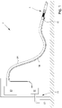
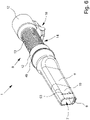
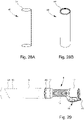
- the 1 shows a suction cleaning attachment 1 of a cleaning device 2, which is used for the interior cleaning of motor vehicles, not shown.
- a suction air flow which rests against the end of the suction cleaning attachment 1, is used for internal cleaning.
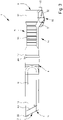
- FIG. 3 shows a suction channel 3 of the suction cleaning attachment 1 for guiding the suction air flow. Furthermore, in 3 the housing 4 of the suction cleaning attachment 1 is shown, which has the suction channel 3 . In addition to the suction channel 3, a compressed air channel 5 for guiding a compressed air flow is arranged in the housing 4. In a further exemplary embodiment, not shown, the housing 4 can be assigned a compressed air duct 5 in addition to the suction duct 3 for guiding a compressed air flow, i.e. in particular firmly connected to the housing 4 but not arranged or provided within the housing 4 .
- the compressed air flow is jet-shaped out of the compressed air channel 5 via the compressed air opening 6 .
- the compressed air cone is only slightly fanned out.
- the compressed air is used to blow out dirt particles from areas that are difficult to access.
- the suction channel 3 is formed independently of the compressed air channel 5.
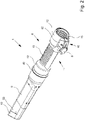
- the in the 2 and 6 Schematically shown in perspective vacuum cleaning attachment 1 has a grip area 14 which is provided for gripping the vacuum cleaning attachment 1 with one hand.
- the handle area 14 is designed in such a way that the vacuum cleaning attachment 1 can be held or guided by the user's hand gripping the handle area 14 .
- both of the user's hands are not required to hold and guide the vacuum cleaning attachment 1 .
- the hand does not have to grip the grip area 14 of the vacuum cleaning attachment 1 completely around the circumference. It is also sufficient to grip the vacuum cleaning attachment 1 in sections or areas for safe guidance of the vacuum cleaning attachment 1 .
- the outer diameter of the handle area 14, in particular the handle section area 13, is between 4 cm and 15 cm, preferably between 6 cm and 10 cm, in particular at least essentially 7 cm.
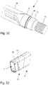
- FIG. 2 shows that a switch 16 is provided to control the flow of compressed air.
- the switch 16 is arranged on the handle area 14 in such a way that the switch 16 can be actuated by a hand gripping the handle area 14 with the same hand.
- the switch 16 shown is also arranged and designed in such a way that it can be actuated in particular by just one finger, preferably the little finger or the thumb, of the user's hand gripping the grip area 14 . Accordingly, the flow of compressed air can easily be switched on during suction operation during the cleaning of motor vehicles.
- the switch 16 shown in the exemplary embodiments has a pivoted lever 51 which can be pivoted into different positions for controlling or releasing the flow of compressed air.
- the pivoting lever 51 is pivotably mounted at one end, with its other, free end being designed for actuating the switch, in particular having an actuating section.
- the switch 16 can also be in the form of a pushbutton switch and/or switch plunger.
- the switch 16 is designed in such a way that it is arranged adjacent to the grip area 14 or in the grip area 14 and can be actuated by the hand of the user gripping the grip area 14 .
- the pivoting lever 51 is loaded by at least one spring 17 .
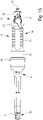
- the spring 17 is also shown in the exploded view of the vacuum cleaning attachment 1 in figure 5 shown.
- the switch 16 can have the pivoting lever 51 and a switch housing 52 as the outer housing, as is the case, for example, in FIGS 2 and 3 is shown.
- the switch housing 52 can be arranged in a fixed or non-pivoting manner on the housing 4 of the vacuum cleaning attachment 1, in particular at least in some areas adjacent to the handle area 14.
- the pivoting lever 51 is arranged on the upper side on the switch housing 52 and is ultimately designed as a pivotable lever.
- the pivoted lever 51 extends into the handle area 14 and can be actuated, in particular pivoted, by a hand grasping the handle area 14 .
- the other components of the switch 16 can also be arranged in the housing of the switch 16 be that work together to release or block the flow of compressed air.
- the compressed air connection 15, such as 2 can be seen to be arranged.
- the compressed air flow can be fed to the vacuum cleaning attachment 1 via the compressed air connection 15, with the compressed air flow in the illustrated exemplary embodiments always being present at the compressed air connection 15 when using the vacuum cleaning attachment 1 and can ultimately be transferred via the switch 16 into the compressed air channel 5.
- the switch housing 52 is arranged on the housing 4 of the vacuum cleaning attachment 1 in such a way that it adapts or nestles to the shape of the housing 4 .
- a switch 16 can be realized with the lowest possible installation height of a few centimeters, in particular from 1 cm to 3 cm.
- the pivoting lever 51 is of at least one compressed air flow blocking blocking position in the Figures 2 to 4 is shown, in at least one release position releasing the compressed air flow, which is in the 13 and 22 is shown, pivotable or displaceable.
- the transfer of the pivoted lever 51 into the release position, starting from the locked position, can be carried out by an adjusting force exerted on the pivoted lever 51 against the spring force of the spring 17 by at least one finger of the hand of a user gripping the gripping area 14 at least in certain areas.
- the pivoted lever 51 can be pivoted and/or displaced from the release position into the blocking position by the spring force of the spring 17 .
- a force In order to move from the locked position to the release position, a force must ultimately be exerted on the pivoted lever 51 .
- the pivoting lever 51 can be returned "independently" from the release position to the locked position without the application of external force.
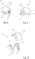
- FIG. 16 shows the switch 16 without the pivoted lever 51 in a first representation, in which the switch housing 52 is clearly visible, and in a second representation that shows the switch 16 without the compressed air connection 15, without pivoted lever 51 and without the switch housing 52.
- the switch 16 is shown in the release position. 14 shows a cross-sectional view of the switch 16 on the underside of the vacuum cleaning attachment 1.
- the Figures 22 to 24 correspond to the 13 and 14 , where the Figures 22 to 24 show the switch 16 in detail. This corresponds to the 22 to the 13 and the 24 to the 14 .
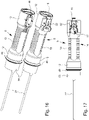
- the spring 17 is tensioned by pivoting the pivoting lever 51, this in the 17 is shown. In this position, the spring force of spring 17 causes the at least essentially rod-shaped or plunger-shaped actuating means 40 to rotate.
- the actuating means 40 interacts with the triggering means 41 in such a way that the actuating means 40 can cause the triggering means 41 to rotate.
- the triggering means 41 is preferably designed as an eccentric disk.
- the actuating means 40 can engage in the triggering means 41 or be guided through the triggering means 41 .
- the actuating means 40 has, at least in regions, an at least essentially rectangular cross-sectional shape, as indicated 24 as can be seen, namely in the section which bears against the triggering means 41 .
- the triggering means 41 has a receiving opening which corresponds to the actuating means 40 and which likewise has an at least essentially rectangular cross section, so that when the actuating means 40 rotates, the triggering means 41 also rotates.
- the actuating means 40 also rotates the triggering means 41 when the pivoting lever is pivoted and/or shifted from the release position into the locked position 26 and 27 as well as the 15 out.
- the 26 is ultimately a detailed representation of the in 15 shown switch 16.
- the 23 and 24 and FIGS. 26 and 27 show that the triggering means 41 interacts with a lock 42.
- the barrier 42 is at least generally spherical in shape, such as, but not limited to, FIG 20 indicates.
- the lock 42 is displaceably mounted in a guide channel 44 having a channel opening 43 .
- the guide channel 44 is in the 20 and 21 shown.
- the channel opening 43 is in 21 apparent.
- the compressed air is routed through the guide channel 44 and made available via the compressed air connection 15 .
- the compressed air present in the guide channel 44 is blocked in the blocking position of the switch 16 by the lock 42 closing the channel opening 43 .
- a channel opening 43 closing lock 42 is in the 26 and 27 shown.
- the 23 and 24 show that in the release position of the switch 16 or the pivoted lever 51, the lock 42 has been displaced by the triggering means 41 in such a way that the compressed air present can be guided or can flow through the duct opening 43 of the guide duct 44 into the compressed air duct 5.
- the lock 42 can be moved in the guide channel 44, whereby in the locked position of the switch 16 or the pivoted lever 51 it terminates with the triggering means 41 or nestles against it such that the channel opening 43 is blocked or closed.
- the channel opening 43 can have a shape or cross section that corresponds to the shape of the barrier 42 , in particular can have an at least essentially circular or round cross section.
- the guide channel 44 can be designed in such a way that the barrier 42 can be guided along the inner wall of the guide channel 44 .
- 20 shows that webs 58 are provided in the guide channel 44, along which the lock 42 is guided can be.
- at least one web 58 can also be provided in further, non-illustrated embodiments.
- the webs 58 are designed in such a way that when the switch 16 or the pivoted lever 51 is in the release position, the compressed air can be transferred or flow from the guide channel 44 via the channel opening 43 into the compressed air channel 5 .
- the compressed air can ultimately flow past the barrier 42 next to the webs 58 .
- the webs 58 therefore serve, among other things, to abut, fix and move the lock 42 in the guide channel 44.
- the webs 58 form areas through which the compressed air can flow past the lock 42, with these areas being in the release position of the Switch 16 and the pivoting lever 51 are created and used.
- FIG 19 is a cross-sectional view of FIG 18 shown vacuum cleaning attachment 1 in the release position of the switch 16 and the pivoting lever 51 shown. 19 makes it clear that the barrier 42 rests on or rests against the webs 58 of the guide channel 44 and the compressed air can flow past between the areas that result between the webs 58 .
- the webs 58 can in particular be designed as projections which protrude beyond the side walls or the base areas of the side walls of the guide channel 44 .
- the guide channel 44 has an at least substantially rectangular cross section, like this 19 indicates.
- the triggering means 41 has at least one projection 45, in the exemplary embodiment shown two projections 45, the projections 45 being designed in such a way that the lock 42 can be displaced to open the channel opening 43 of the guide channel 44.
- the barrier 42 is slid along at least one web 58 .
- the projection 45 engages the surface or the outer surface of the lock 42 .
- the projections 45 of the triggering means 41 are arranged adjacent to the lock 42 in such a way that the channel opening 43 is closed, as shown in FIG 27 is evident.
- the switch 16 shown in the embodiments is based on the pivoted lever 51 in two opposite directions in each case a release position pivotable and/or displaceable from the locked position.
- the above-mentioned projections 45 prove to be particularly advantageous, since two projections 45 can ultimately ensure that, starting from an at least essentially central blocked position of the switch 16 or the pivoted lever 51, the pivoted lever 51 can be transferred into the release position. and in two different directions. If only one projection 45 of the triggering means 41 were present, the pivoting lever 51 could also only be pivoted in one direction.
- the compressed air line 27 of the compressed air duct 5 can at least partially be guided into the switch 16, in particular into the switch housing 52, as is the case, inter alia 26 indicates.
- the cross-sectional area of the compressed air opening 6 of the compressed air channel 5 is approximately 20 mm 2 . In further embodiments, which are not shown here, the cross-sectional area of the compressed air opening 6 of the compressed air channel 5 can be between 0.5 mm 2 and 100 mm 2 . In the exemplary embodiment shown, the cross section of the compressed air duct 5 has an at least essentially circular basic shape and also a diameter of approximately 5 mm.
- the cross-sectional area shown of the suction opening 7 of the suction channel 3 is approximately 450 mm 2 .
- the cross-sectional area of the suction opening 5 of the suction channel 3 can be between 100 mm 2 and 1,000 mm 2 .
- the vacuum cleaning attachment 1 shown in the exemplary embodiments shown has a ratio between the cross-sectional area of the suction opening 7 and the compressed air opening 6 of approximately 22.5:1. In further embodiments it can be provided that the ratio of the cross-sectional area of the suction opening 7 to the cross-sectional area of the compressed air opening 6 is between 10:1 and 100:1.
- an overpressure of 7 bar is provided in the compressed air duct 5 or the compressed air exits the compressed air duct 5 with the aforementioned overpressure.
- the overpressure can be between 5 bar and 10 bar.
- there is a negative pressure which is about 0.5 bar in the illustrated embodiments.
- the negative pressure can be between 0.3 and 0.8 bar.
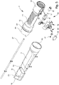
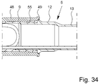
- FIG 5 shows that the housing 4 is designed in several parts or at least in three parts, as can also be seen from the other figures.
- the individual components of the vacuum cleaning attachment 1 and the housing 5 can be designed to be plugged into one another.
- a detachable connection between the multi-part components of the housing 4 of the vacuum cleaning attachment 1 can be provided.
- the housing 4 has a grip section 8 having the grip region 14 , a housing socket 9 which can be releasably connected to the grip portion 8 and an end piece 10 which can be releasably connected to the housing socket 9 .
- the end piece 10, which is subject to greater wear than the rest of the housing 4, can be replaced independently of the other components of the housing 4.
- the detachable connections of the components 8, 9, 10 of the housing 4 to one another allow access to the interior of the housing 4.
- end piece 10 is beveled at the end facing away from the housing connection piece 9 .
- the housing socket 9 can be releasably connected to the handle section 8 in a form-fitting, force-fitting and/or friction-fitting manner.
- the end piece 10 can in turn also be connected to the housing socket 9 in a form-fitting, force-fitting and/or friction-fitting manner.
- the connection is designed in such a way that a loosening of the aforementioned components during use of the vacuum cleaning attachment 1 can be at least essentially avoided.
- suction channel 3 and the compressed air channel 5 are provided at least in sections in the grip section 8 , in the housing connector 9 and in the end piece 10 .
- the suction channel 3 and/or compressed air channel 5 can be provided at least in sections on the housing connector 9 and/or on the end piece 10 .
- the handle portion 8 facing the end piece 10 on the inside has a tapering cross-sectional area.
- FIG. 5 Furthermore shows figure 5 that the handle portion area 13 and / or the handle portion 8 is rotationally symmetrical and / or mirror-symmetrical to a central longitudinal axis.
- FIG. 5 shows figure 5 that the handle section 8 with the connection area 55 can be inserted into the housing socket 9 .
- the housing socket 9 can be inserted into the handle section 8 .
- FIG. 5 shows figure 5 that the housing connector 9 is formed with a connection area 59 in the end piece 10 can be inserted.
- the end piece 10 can also be designed so that it can be inserted into the housing socket 9 .
- Corresponding receiving areas are provided for the respective connection areas 55, 59.
- connection area 56 shows that following the receiving area corresponding to the connection area 55 there is a, in particular conical, narrowing of the suction channel 3 of the housing connection piece 9 .
- an at least essentially hollow cuboid or slit-like shape is formed, as also in figure 5 shown.
- the suction channel 3 has a piece of pipe 11 inserted into the housing socket 9 .
- the pipe section 11 can protrude into the handle section 8 and into the end piece 10 .
- the compressed air channel 5 is designed as a compressed air line 27 and is arranged at least in certain areas in the housing socket 9 and in the handle section 8 .
- the compressed air line 27 can be designed as a hose, in particular a plastic hose.
- the compressed air line 27 ends in the end piece 10, the compressed air channel 5 being subsequently formed by a channel of the end piece 10 adjoining the compressed air line 27 in the direction of flow.
- the compressed air line 27 is held on the piece of pipe 11 .
- the compressed air line 27 can be clamped on the pipe section 11 or held by the pipe section 11 via appropriate holding means.
- the compressed air channel 5, in particular the compressed air line 27, extends at least in some areas from the suction channel into the housing connector 9 at least one separating strip 46 is separated.
- the separating strip 46 (not shown) can be fixed to the housing socket 9 and to the inner wall 47 of the housing socket 9 by means of a screw connection. The screw connection is shown schematically in the exploded view in figure 5 apparent.
- the separating strip 46 serves to space the compressed air line 27 from the suction channel 3.
- the compressed air channel 5 shown is adjacent to the inner wall 47 of the housing socket 9 and to the inner wall of the handle section 8 .
- separating strip 46 is connected to the inner wall 47 of the housing socket 9, in particular by screw connections.
- corresponding depressions for the compressed air line 27 are provided on the inner wall 47 of the housing connector 9 and/or on the inner wall of the handle section 8 for at least regionally receiving the compressed air line 27 .
- the compressed air line 27 can be guided safely through the handle section 8 and/or the housing connection piece 9 by means of the indentations, which are not shown in detail.
- a channel accommodating the compressed air line 27 can also be provided, in particular adjacent to the inner wall 47 of the housing connection piece 9 and/or the inner wall of the handle section 8, which duct accommodates the compressed air line 27 and ultimately to the Tail 10 leads.
- the handle section 8 has two outer connection ends 12 and a handle section area 13 provided between the connection ends 12 .
- the outer diameters of the terminal ends 12 are each larger than the outer diameter of the handle section area 13.
- the handle section area 13 can form the handle area 14.
- the suction channel 3 can taper towards the suction opening 7 in the area of the handle section area 13 and the housing connection piece 9 .
- the switch 16 and the switch housing 52 are arranged on the handle section 8 in the illustrated exemplary embodiments.
- the 16 shows that the switch housing 52 is arranged on the connection end 12 of the handle section 8 facing away from the suction opening 7 and extends at least in certain areas into the handle section area 13 .
- the pivoting lever 51 is adjacent to the handle section area 13 and protrudes with its free end, which is used for actuation, into the handle area 14, such as this in particular 13 emerges.
- connection end 12 and the handle section area 13 have an at least essentially hollow-cylindrical shape.
- the handle section area 13 is ultimately freely accessible from the outside and is not impeded by other components, in particular not by a bracket spanning the handle section area 13 .
- a user can grasp the grip section area 13 of the vacuum cleaning attachment 1 from any side or in any position.
- the suction cleaning attachment 1 can be easily guided to clean the interior of motor vehicles.
- connection end 12 in the illustrated embodiment, both outer diameters of the connection ends 12, is formed larger than the outer diameter of the handle section area 13.
- the outer diameter of at least one connection end 12 is at least 10% larger than the outer diameter of the handle section area 13 .
- the aforementioned difference between the outer diameters results in a defined length of the grip section area 13 and, moreover, a limitation of the movement of the hand on the grip section area 13 in the state of use is specified.
- the handle section area 13 has a corrugation and/or a structured surface on the outside.
- the corrugation is in the form of grooves—in the manner of grooves lined up in a row—with the grooves being arranged at a distance from one another on the outside of the handle section region 13 .
- a lighting device 18 can be provided for the vacuum cleaning attachment 1 .
- the lighting device 18 has at least one LED.
- the lighting device 18 is held on the pipe section 11 and on the housing socket 9 in an exemplary embodiment that is not shown.
- the lighting device 18 can be arranged on the end piece 10, on the housing socket 9, on the handle section 8, on the bracket 14 and/or on the pipe piece 11, in particular firmly connected to the aforementioned components.
- the lighting device 18 is connected via at least one line 19 for carrying current.
- the line 19 is connected to a power connection 24 which may be provided on the switch 16 .
- the line 19 can be held on the pipe section 11 and fed to the lighting device 18 on the side of the pipe section 11 opposite the compressed air line 27 .
- the line 19 can be arranged and/or held on the inside of the pipe piece 11 , on the outside of the suction channel 3 and/or on the inside of the end piece 10 .
- the power connection 24 can be provided adjacent to the compressed air connection 15 .
- the lighting device 18 is arranged on the housing socket 9 and on the pipe section 11 in the channel 33 and in the housing socket 9 .
- the end piece 10 can partially cover the housing socket 9 on the outside, so that the lighting device 18 can also be surrounded by the end piece 10 on the outside.
- the lighting device 18 is arranged on the outside of the pipe section 11 facing the housing connection piece 9 .
- An LED cover protects the LED and/or the lighting device 18 from dirt.
- the resulting light beam is larger or wider than the light beam generated due to the spacing of the light exit opening 34 from the suction opening 7 or the compressed air opening 6 when using the vacuum cleaning attachment 1 for cleaning the interior of motor vehicles.
- the vacuum cleaning attachment 1 shown has a housing 4 made of a plastic material.
- the plastic material includes polyethylene (PE).
- the material of the housing 4, the end piece 10, the housing socket 9, the switch 16, the pivoting lever 51, the switch housing 52, the handle section 8 and/or the guide channel 44 can be a preferably thermoplastic plastic, preferably polyethylene (PE ), polypropylene (PP), polyvinyl chloride (PVC) and/or polystyrene (PS).
- a bracket-like line fastening means 28 is fastened adjacent to the compressed air connection 15, which is designed to fix the line of the compressed air device 21 and the energy supply device 25, for example by means of cable ties.
- the vacuum cleaning attachment 1 shown is intended to be inserted and held in a quiver 48 when it is not in use.
- a holder of the suction cleaning attachment 1 in the quiver 48 is, for example, in the 29 and 30 shown.
- the non-use state is ultimately before and after the interior cleaning of the motor vehicle before or when the vacuum cleaning attachment 1 is not used for interior cleaning.
- the suction cleaning attachment 1 in the quiver 48 as from 30 visible, used and kept in it.
- the handle area 14 can also be understood as that area of the vacuum cleaning attachment 1 which is arranged outside of the holder 48 or above the outer edge 57 of the holder 48 when the vacuum cleaning attachment 1 is inserted into the holder 48 .
- FIG. 6 also shows that on the outside of the housing 4 between the suction opening 7 and the handle area 14 there is a stop 49 that protrudes beyond the handle area 14 for interaction with the outer edge 57 of the holder 48 . Interaction between the stop 49 and the outer edge 57 or the outer edge of the holder 48 is, among other things, 29 shown.
- stop 49 is designed as a step.
- FIG 5 shows that the stop 49 is designed as a peripheral, in particular ring-shaped, projection.
- the stop 49 is at least substantially straight, uninterrupted and/or planar on its arrangement surface facing the outer edge 57 of the holder 48 .
- the stop 49 can be designed to correspond to the outer edge 57 of the quiver 48 so that when the vacuum cleaning attachment 1 is inserted into the quiver 48 there is a pressure-tight and friction-locked connection.
- the stop 49 ultimately represents a limitation of the insertion movement of the vacuum cleaning attachment 1 into the quiver 48. In particular, no movement beyond the stop 49 into the quiver 48 is possible. This is particularly important because, in the prior art, the vacuum cleaning attachment 1 is often inserted very firmly into the holder 48 by the user, resulting in a very firm frictional connection, which often makes it very difficult to remove the vacuum cleaning attachment 1 again pull out the quiver 48. This problem is completely avoided in the invention.
- figure 5 shows that the stop 49 is arranged on the connection end 12 facing the suction opening 7 .
- the stop 49 protrudes beyond the connection end 12 on the outside.
- the 32 shows that the stop 49 is directly adjacent to the housing socket 9 .
- the stop 49 protrudes both over the connection end 12 and over the housing socket 9 .
- the stop 49 has a width that exceeds the material thickness of the housing socket 9 .
- the width or height of the stop 49 depends in particular on the insertion path of the vacuum cleaning attachment 1 in the quiver 48 and depending on the outer edge 57 of the quiver 48 is formed.
- the stop 49 which is designed in particular as a step, is arranged on the outside of the housing connection piece 9 .
- the stop 49 would not necessarily have to protrude beyond the handle area 14, the handle section 8 and/or the connection end 12.
- the stop 49 should be designed to limit the insertion movement into the quiver 48 . Ultimately, this presupposes that behind the stop 49—facing the suction opening 7—there is no elevation or enlargement of the suction cleaning attachment 1 or the housing 4 that exceeds the stop 49 .
- Figure 33 shows that the end piece 10 has a bevel 56 at the suction end forming the suction opening 7 .
- the incline 56 can be designed in particular as an incline of 45° ⁇ 15°.
- Out of Figure 33 also shows that the end piece 10 has a marking 53 on the outside, in particular running parallel to the bevel 56, as a wear indicator.
- the marking 53 is arranged in such a way that it is arranged on the end piece 10 connected to the housing connection piece 9 at a distance from the outer edge 50 of the housing connection piece 9 facing the suction opening 7 .
- the outer edge 50 of the housing socket 9 is in 4 shown.
- a cleaning device 2 for cleaning the interior of motor vehicles is shown.
- the cleaning device 1 has a suction cleaning attachment 2 of the type described above.
- the cleaning device 2 has a fan device 20 for generating a negative pressure and a compressed air device 21 .
- the compressed air device 21 has a compressed air reservoir 22 and a compressed air generator 23 .
- the compressed air is stored or stored in the compressed air reservoir 22 and the required excess pressure of the compressed air flow is generated by the compressed air generator 23 .
- the compressed air device 21 is assigned to the compressed air channel 5 of the vacuum cleaning attachment 1 and the blower device 20 is assigned to the suction channel 3 of the vacuum cleaning attachment 1 .
- an assignment takes place in such a way that the blower device 20 is connected in terms of flow to the vacuum cleaning attachment 1 via a suction hose 26 .
- the compressed air channel 5 is connected to the compressed air device 21 via the compressed air connection 15 via a further compressed air line.
- the further compressed air line can be designed as a compressed air connection line 36 .
- the switch 16 of the vacuum cleaning attachment can release the compressed air flow provided by the compressed air connection line 36 and accordingly transfers the compressed air flow to the compressed air channel 5. Ultimately, the switch 16 can block the compressed air flow provided by the compressed air connection line 36 and the compressed air flow cannot be transferred to the compressed air channel 5.
- the lighting device 18 is connected via a power connection via a further power line to an energy supply device that provides the required power for the lighting device 18 .
- the energy supply device can have an energy store, for example an accumulator.
- the energy supply device can also be designed as a connection to the public power grid.
- the energy supply device can be controlled via a control cabinet.
- the lighting device 18 of the vacuum cleaning attachment 1 can be coupled to the blower device 20, the switch 16 and/or the compressed air device 21, in particular the valve of the compressed air device 21.
- the lighting device 18 can be switched on in the suction mode and/or in the compressed air mode.
- a plurality of lighting means of the lighting device 18 can be provided, which can be controlled independently of one another, for example.
- the vacuum cleaning attachment 1 is torsionally rigid with the suction hose 26 in the 8 illustrated embodiment connected. What is not shown is that an anti-twist device 37 in the form of a clamping screw is provided on the connection end 12 and interacts with the suction hose 26 .
- FIG. 7 shows that a compressed air connection line 36 connecting the vacuum cleaning attachment 1 to the compressed air device 21 is connected to the suction hose 26 via at least one fastening means 29 .
- the compressed air connection line 36 is connected to the compressed air connection 15 .
- connection line 35 connecting the lighting device 18 to an energy supply device via at least a fastener 29 is connected to the suction hose 26.
- the connection line 35 can be connected to the power connection and .
- the fastening means 29 is connected to the corrugated suction hose 26 via a detachable latching connection. 12 shows that the fastening means 29 is locked with a grooved leg 30 of the suction hose 26. That in the Figures 8 to 10 Fastening means 29 shown is in several parts and designed to accommodate the compressed air connection line 36 and optionally an electrical connection line 35 (not shown).
- the fastening means 29 has two side parts 31 to be latched together and an attachment 32 to be positively connected to the side parts 31, the attachment 32 having a rounded or curved outer side 38 to cover sharp edges of the side parts 31.
- the rounded design of the attachment 32 results in a cross-sectional shape of the attachment 32 and the fastening means 29 that is at least essentially in the form of a segment of an arc.
- the fastening means 29 has a receptacle with at least two, in which in 10 embodiment shown three, receiving areas 39 on. 7 shows that the compressed air connection line 36 is provided in the receiving area 39 and is securely fixed in it.
- Two receiving areas 39 are provided for the at least one electrical connecting line 35 (not shown), so that the fastening means 29 can be latched to the suction hose 26 independently of the electrical connecting line 35 being seated, as is also evident 7 results.
- FIG. 7 shows that the bending radius and/or the freedom of movement of the suction hose 26 is not reduced or restricted by the fastening means 29.
- a plurality of fastening means 29 for fixing the compressed air connection line 36 to the suction hose 26 is provided.
- the compressed air connection line 36 is arranged on the suction hose 26 via the fastening means 29 in such a way that it is or is provided in alignment with the compressed air connection 15 and the power connection 24 .
- a quiver 48 is in accordance with 30 provided in a cleaning device 2 for holding the vacuum cleaning attachment 1 when not in use.
- the compressed air device 21 and the compressed air connection line 36 are not shown for reasons of clarity.
- the quiver 48 is shown.
- the quiver 48 can be in the form of a hollow cylinder.
- the quiver 48 is closed at the end on its underside and has a quiver opening opposite the underside.
- the quiver 48 illustrated provides that the outer edge 57 of the quiver 48 is at least substantially flush with the stop 49 of the vacuum cleaning attachment 1 when it is not in use, as in 29 shown.
- Figure 28B shows that the outer edge area can be understood as the outer edge 57 of the quiver 48 .
- the outer edge 57 has an inner stop which can be at least essentially flush with the stop 49 of the vacuum cleaning attachment 1 when it is not in use.
- the stop 49 of the suction cleaning attachment 1 when not in use and when inserted in the quiver 48 can be surrounded at least in regions by the outer edge 57 of the quiver 48, as shown in FIG 34 apparent.
- the outside diameter of the outer edge area 57 of the holder 48 can be at least essentially equal to the outside diameter of the stop 49 of the vacuum cleaning attachment 1 .
- the mutually facing surfaces of the stop 49 and the step formed in the quiver 48 rest on one another, so that the stop function described above ultimately results.
- 34 also shows that the inner diameter of the inner stop of the outer edge 57 of the quiver 48 is greater than or equal to the largest outer diameter of the front region arranged behind (i.e. facing the closed underside of the quiver 48) the inner stop of the quiver 48 when inserted in the quiver 48 of the vacuum cleaning attachment 1 is formed.
- the stop 49 of the vacuum cleaning attachment 1 interacts with the outer edge 57 of the holder 48 in such a way that an at least essentially pressure-tight seal results.
- the pressure-tight seal results when not in use.
- the negative pressure is in particular provided continuously by the blower device 20 . Due to the pressure-tight closure, an at least essentially self-contained system can be provided if the cleaning device 2 only has a suction cleaning attachment 1 .
- the cleaning device 2 has a plurality of suction cleaning attachments 1 . It is also possible for only one vacuum cleaning attachment 1 to be inserted into the quiver 48 while another vacuum cleaning attachment 1 is being used. In this case there would be no self-contained system, but the electrical energy required for the blower device 20 is reduced by the arrangement of at least one vacuum cleaning attachment 1 in the holder 48 and the pressure-tight seal between the holder 48 and the vacuum cleaning attachment 1 .
- the blower device 20 has a control device 24 .
- the control device 24 can reduce the electrical energy supplied to the blower device 20 from an energy supply device 25 for generating the negative pressure while the vacuum cleaning attachment 1 is in the inserted state in the holder 48 .
- At least one pressure sensor can be assigned to the control device 24, which in particular measures and/or determines the pressure difference to be overcome. If the suction cleaning attachment 1 is inserted into the quiver 48 and there is a pressure-tight seal between the outer edge 57 of the quiver 48 and the stop 49, the pressure difference in particular is very small. As a result, the electrical energy provided by the energy supply device 25 for the blower device 20 can be reduced.
- the method for cleaning the interior of motor vehicles is not shown in the exemplary embodiments shown.
- the cleaning device 1 explained above is used in the method for cleaning the interior of motor vehicles.
- dirt and/or particles are sucked off in the suction mode, dirt and/or particles being able to be whirled up by means of a compressed air flow during the suction mode in the compressed air mode.
- Compressed air operation can be switched on via switch 16.
- the method can be operated in a suction mode, a compressed air mode, a suction and compressed air mode and a suction mode with the pressure mode being switched on as required. Due to the compressed air flow, particles, in particular those that are difficult to access, can be swirled or whirled up and then sucked up via the suction air flow.
- This method can also be used to reliably remove dirt particles from areas of the interior of motor vehicles that are difficult to reach.
- the dirt particles can be removed from areas that are difficult to access and blown or transported to easily accessible areas by means of the compressed air flow. The dirt particles can then be sucked up or removed from the easily accessible areas by the suction air flow.
Landscapes
- Engineering & Computer Science (AREA)
- Mechanical Engineering (AREA)
- Cleaning In General (AREA)
Description
Die Erfindung betrifft die Verwendung eines Saugreinigungsvorsatzes einer Reinigungsvorrichtung zur Innenreinigung von Kraftfahrzeugen mittels einer Saugluftströmung, mit einem einen Saugkanal zum Führen der Saugluftströmung aufweisenden Gehäuse.The invention relates to the use of a suction cleaning attachment of a cleaning device for cleaning the interior of motor vehicles by means of a suction air flow, with a housing having a suction channel for guiding the suction air flow.
Reinigungsvorrichtungen der vorgenannten Art werden auch als Autostaubsauger bezeichnet, die üblicherweise im gewerblichen Bereich eingesetzt werden, wobei mittels des Saugreinigungsvorsatzes bzw. der Staubsaugdüse Schmutz und/oder Partikel aus dem Innenraum des Fahrzeugs gesaugt werden. Die Reinigungsvorrichtung ist in der Regel derart ausgebildet, dass Schmutz und/oder Partikel von einem Untergrund, beispielsweise den Sitzen und/oder den Bodenmatten, aufsaugbar sind.Cleaning devices of the aforementioned type are also referred to as car vacuum cleaners, which are usually used in the commercial sector, with dirt and/or particles being sucked out of the interior of the vehicle by means of the vacuum cleaning attachment or the vacuum cleaner nozzle. The cleaning device is generally designed in such a way that dirt and/or particles can be sucked up from a substrate, for example the seats and/or the floor mats.
Allerdings ergeben sich in der Praxis Probleme bei der Innenreinigung von Kraftfahrzeugen. Im Fahrzeuginnenraum sind viele Bereiche gar nicht oder nur schwer bei der Reinigung zugänglich, so dass diese Bereiche auch nicht oder nicht hinreichend gereinigt werden können. Dies betrifft beispielsweise den Bereich zwischen den Autositzen, aber auch Bereiche, die verwinkelt oder schlecht zugänglich sind. Demgemäß ist keine effiziente Absaugung von Schmutzpartikeln in den vorgenannten Bereichen möglich.However, problems arise in practice when cleaning the interior of motor vehicles. Many areas of the vehicle interior are not accessible at all or only with difficulty for cleaning, so that these areas cannot be cleaned or cannot be cleaned sufficiently. This applies, for example, to the area between the car seats, but also to areas that are angled or difficult to access. Accordingly, no efficient suction of dirt particles in the aforementioned areas is possible.
Im Stand der Technik ist zur Verbesserung der Innenreinigung von Kraftfahrzeugen vorgesehen, dass im Gehäuse zusätzlich zum Saugkanal ein Druckluftkanal zum Führen einer Druckluftströmung vorgesehen ist und/oder dass dem Gehäuse zusätzlich zum Saugkanal ein Druckluftkanal zum Führen einer Druckluftströmung zugeordnet ist.In the prior art, to improve the interior cleaning of motor vehicles, a compressed air channel for guiding a compressed air flow is provided in the housing in addition to the suction channel and/or a compressed air channel for guiding a compressed air flow is assigned to the housing in addition to the suction channel.
Dass der Druckluftkanal dem Gehäuse zugeordnet ist, ist insbesondere derart zu verstehen, dass der Druckluftkanal zwar nicht im Gehäuse des Saugreinigungsvorsatzes verläuft, sondern beispielsweise außenseitig am Gehäuse vorgesehen ist, dann jedoch vorzugsweise fest mit dem Gehäuse verbunden ist. Der Austritt der Druckluft aus dem Druckluftkanal ist insbesondere strahlförmig, so dass der Druckluftstrahl bzw. die Druckluftströmung ziel- und zweckgerichtet auf einen zu reinigenden, insbesondere schwer zugänglichen, Bereich gerichtet werden kann. Die Druckluftströmung kann bedarfsweise während des Saugbetriebes zugeschaltet und dann gleichzeitig mit der Saugluftströmung zur Innenreinigung von Kraftfahrzeugen eingesetzt werden.The fact that the compressed air duct is assigned to the housing is to be understood in particular in such a way that the compressed air duct does not run in the housing of the vacuum cleaning attachment, but is provided, for example, on the outside of the housing, but is then preferably firmly connected to the housing. The exit of the compressed air from the compressed air duct is in particular in the form of a jet, so that the compressed air jet or the compressed air flow can be directed in a targeted and purposeful manner onto an area to be cleaned, in particular one that is difficult to access. the If necessary, the compressed air flow can be switched on during suction operation and then used simultaneously with the suction air flow for cleaning the interior of motor vehicles.
Im Stand der Technik ist daher ist eine Kombination einer Druckluftströmung und einer Saugluftströmung, die beide bevorzugt im vorderen Bereich aus dem erfindungsgemäßen Saugreinigungsvorsatz austreten, bekannt. Die Druckluftströmung ist dabei zum Aufwirbeln von Partikeln und/oder Schmutz, insbesondere Staubpartikeln, an schwer zugänglichen Bereichen vorgesehen. So kann die Druckluft gezielt auf schwer zugängliche Bereiche gerichtet werden und in diesen Bereichen die Schmutzpartikel aufwirbeln, welche anschließend durch die Saugluftströmung absaugbar sind. Die Schmutzpartikel können mittels Druckluft aus schwer zugänglichen Bereichen, insbesondere Spalten, Vertiefungen und/oder Schlitzen, in offene und/oder für die Saugluftströmung und/oder den Saugreinigungsvorsatz zugängliche Bereiche transportiert werden, wobei die Schmutzpartikel in diesen Bereichen absaugbar sind. Hierdurch erhöht sich die Reinigungseffizienz der Reinigungsvorrichtung im Vergleich zum "reinen" Saugbetrieb signifikant, da eine Reinigung nicht nur an leicht zugänglichen Bereichen im Fahrzeuginnenraum, sondern auch in Bereichen, die mit der Mündung des Saugreinigungsvorsatzes nicht unmittelbar zu erreichen sind, gewährleistet werden kann.A combination of a compressed air flow and a suction air flow, both of which preferably emerge from the suction cleaning attachment according to the invention in the front region, is therefore known in the prior art. The compressed air flow is intended to whirl up particles and/or dirt, in particular dust particles, in areas that are difficult to access. In this way, the compressed air can be directed to areas that are difficult to access and whirl up the dirt particles in these areas, which can then be sucked off by the suction air flow. The dirt particles can be transported by means of compressed air from areas that are difficult to access, in particular gaps, depressions and/or slots, into open areas and/or areas accessible to the suction air flow and/or the vacuum cleaning attachment, with the dirt particles being able to be sucked off in these areas. This significantly increases the cleaning efficiency of the cleaning device compared to "pure" suction operation, since cleaning can be guaranteed not only in easily accessible areas of the vehicle interior, but also in areas that cannot be reached directly with the mouth of the suction cleaning attachment.
Der Druckluftkanal kann unabhängig von dem Saugkanal ausgebildet sein. Beide Kanäle verlaufen letztlich getrennt voneinander, da der Saugbetrieb und der Druckluftbetrieb gleichzeitig erfolgen können. Der Saugbetrieb und der Druckluftbetrieb sind damit voneinander entkoppelt. Allerdings können die jeweiligen Austrittsöffnungen aus den jeweiligen Kanälen für die Druckluftströmung und die Saugluftströmung zumindest im Wesentlichen in einer gemeinsamen Ebene vorgesehen sein. Insbesondere treten die Saugluft und die Druckluft an der vorderseitigen Mündung des Saugreinigungsvorsatzes aus.The compressed air channel can be formed independently of the suction channel. Ultimately, both channels run separately from one another, since the suction operation and the compressed air operation can take place at the same time. The suction operation and the compressed air operation are thus decoupled from each other. However, the respective outlet openings from the respective channels for the compressed air flow and the suction air flow can be provided at least essentially in a common plane. In particular, the suction air and the compressed air exit at the front opening of the vacuum cleaning attachment.
Vorteilhaft an dem vorgenannten Saugreinigungsvorsatz ist, dass dieser an bereits bestehenden Reinigungsvorrichtungen, insbesondere Autostaubsauger, anschließbar ist.The advantage of the aforementioned vacuum cleaning attachment is that it can be connected to existing cleaning devices, in particular car vacuum cleaners.
Nachteilig an dem vorgenannten aus dem Stand der Technik bekannten Saugreinigungsvorsatz ist, dass dieser vergleichsweise unhandlich und letztlich schwer zu bedienen ist. Ein Zuschalten der Druckluftströmung ist dergestalt durchzuführen, dass ein Umgreifen des Saugreinigungsvorsatzes erfolgen muss. Zum Einschalten des Druckluftbetriebes sind beim Stand der Technik Betätigungseinrichtungen vorgesehen, die eine weitere Hand und/oder eine weitere Bedienperson benötigen. Die Betätigung muss beidhändig erfolgen.A disadvantage of the aforementioned vacuum cleaning attachment known from the prior art is that it is comparatively unwieldy and ultimately difficult to operate. The compressed air flow must be switched on in such a way that the suction cleaning attachment must be gripped. To switch on the compressed air operation are provided in the prior art actuators that require another hand and / or another operator. It must be operated with both hands.
Bei dem bekannten Saugreinigungsvorsatz ist außenseitig am Gehäuse ein Griffbereich zum Greifen des Saugreinigungsvorsatzes mit einer Hand vorgesehen. Während des Saugbetriebes wird der Saugreinigungsvorsatz zumindest bereichsweise am Griffbereich durch die Hand eines Benutzers umgriffen, so dass der Saugreinigungsvorsatz gehalten und geführt werden kann. Letztlich ist es allerdings so, dass zum Zuschalten des Druckluftbetriebes die weitere Hand genutzt und/oder der Saugbetrieb bzw. das Absaugen unterbrochen werden muss.In the known vacuum cleaning attachment, a grip area for gripping the vacuum cleaning attachment with one hand is provided on the outside of the housing. During suction operation, the hand of a user grasps at least some areas of the grip area, so that the suction cleaning attachment can be held and guided. Ultimately, however, it is the case that the other hand has to be used to switch on the compressed air operation and/or the suction operation or suction has to be interrupted.
Demzufolge ist die Aktivierung des Druckluftbetriebes beim Stand der Technik nur mit einem vergleichsweise hohen Aufwand durchführbar, was letztlich auch die benötigte Zeit zur Innenreinigung von Kraftfahrzeugen erhöht und zudem dazu führen kann, dass die zuvor beschriebene vorteilhafte Druckluftströmung nur selten zur Innenreinigung von Kraftfahrzeugen genutzt wird, worunter das Reinigungsergebnis leidet.As a result, the activation of the compressed air operation in the prior art can only be carried out with a comparatively high level of effort, which ultimately also increases the time required for cleaning the interior of motor vehicles and can also lead to the advantageous compressed air flow described above being used only rarely for cleaning the interior of motor vehicles. which affects the cleaning result.
Die
Die
Die
Aufgabe der vorliegenden Erfindung ist es nun, die vorgenannten Nachteile des Standes der Technik zu vermeiden oder aber zumindest im Wesentlichen zu reduzieren. Insbesondere ist es die Aufgabe der vorliegenden Erfindung, einen Saugreinigungsvorsatz bereitzustellen, mit dem in kurzer Zeit ein gutes Reinigungsergebnis erzielbar ist.The object of the present invention is now to avoid the aforementioned disadvantages of the prior art or at least to substantially reduce them. In particular, the object of the present invention is to provide a vacuum cleaning attachment with which a good cleaning result can be achieved in a short time.
Erfindungsgemäß ist zur Lösung der vorgenannten Aufgabe eine Verwendung eines Saugreinigungsvorsatzes einer Reinigungsvorrichtung zur Innenreinigung von Kraftfahrzeugen mittels einer Saugluftströmung vorgesehen. Der Saugreinigungsvorsatz ist mit einem einen Saugkanal zum Führen der Saugluftströmung aufweisenden Gehäuse versehen. Im Gehäuse ist zusätzlich zum Saugkanal ein Druckluftkanal zum Führen einer Druckluftströmung vorgesehen und/oder dem Gehäuse ist zusätzlich zum Saugkanal ein Druckluftkanal zum Führen einer Druckluftströmung zugeordnet. Außenseitig ist am Gehäuse ein Griffbereich - vorgesehen zum Greifen des Saugreinigungsvorsatzes mit einer Hand - vorgesehen. Erfindungsgemäß ist ein Schalter, nämlich ein Schwenkhebel, zur Steuerung der Druckluftströmung vorgesehen, wobei der Schalter am Griffbereich und/oder im Bereich und/oder in der Nähe des Griffbereichs derart angeordnet ist, dass der Schalter durch eine den Griffbereich umfassende Hand mit derselben Hand betätigbar ist.According to the invention, the use of a suction cleaning attachment of a cleaning device for the interior cleaning of motor vehicles by means of a suction air flow is provided to achieve the above-mentioned object. The suction cleaning attachment is provided with a housing having a suction duct for guiding the flow of suction air. In addition to the suction channel, a compressed air channel for guiding a compressed air flow is provided in the housing and/or the housing is assigned a compressed air channel for guiding a compressed air flow in addition to the suction channel. On the outside of the housing there is a gripping area—provided for gripping the vacuum cleaning attachment with one hand. According to the invention, a switch, namely a pivoted lever, is provided for controlling the flow of compressed air, the switch being arranged on the handle area and/or in the area and/or in the vicinity of the handle area in such a way that the switch can be actuated by a hand gripping the handle area with the same hand is.
Durch Betätigung des Schalters kann eine Freigabe der Druckluftströmung ausgelöst werden. Daher kann der Druckluftanschluss mit dem Schalter verbunden sein, vorzugsweise unmittelbar.A release of the compressed air flow can be triggered by actuating the switch. Therefore, the compressed air connection can be connected to the switch, preferably directly.
Zudem wird durch die erfindungsgemäße Anordnung des Schalters eine einfache Bedienung des Saugreinigungsvorsatzes ermöglicht, bei der der Druckluftbetrieb bzw. die Druckluftströmung bei Nutzung des Saugreinigungsvorsatzes zum Saugen in einfacher Weise mit der gleichen Hand, die den Saugreinigungsvorsatz hält, zugeschaltet werden kann. Letztlich wird keine weitere Hand zur Betätigung des Schalters benötigt.In addition, the arrangement of the switch according to the invention enables simple operation of the vacuum cleaning attachment, in which the compressed air operation or the compressed air flow when using the vacuum cleaning attachment for vacuuming can be switched on easily with the same hand that is holding the vacuum cleaning attachment. Ultimately, no other hand is required to operate the switch.
Dies ergibt eine ergonomisch deutlich vereinfachte Verwendung des Saugreinigungsvorsatzes, bei der zudem die Effizienz der Innenreinigung von Kraftfahrzeugen erhöht werden kann.This results in an ergonomically significantly simplified use of the vacuum cleaning attachment, in which the efficiency of the interior cleaning of motor vehicles can also be increased.
Eine Erhöhung der Effizienz ergibt sich nicht zuletzt dadurch, dass das Zuschalten der Druckluftströmung zur verbesserten Absaugung von schwer zugänglichen Schmutzpartikeln während des Saugbetriebes einfach durchgeführt werden kann, so dass Zeit eingespart wird. Es versteht sich, dass sich die Effizienzsteigerung auch dann ergibt, wenn während des Druckluftbetriebes keine Saugluftströmung benötigt wird - d.h. während des Druckluftbetriebes der Saugbetrieb eingestellt wird.An increase in efficiency results not least from the fact that switching on the compressed air flow for improved suction of dirt particles that are difficult to access can be carried out easily during suction operation, so that time is saved. It goes without saying that the increase in efficiency also results when no suction air flow is required during compressed air operation - i.e. suction operation is stopped during compressed air operation.
Der Schalter kann mit einem Ventil einer Drucklufteinrichtung, insbesondere eines Druckluftspeichers, gekoppelt sein, wobei die Drucklufteinrichtung dem Druckluftkanal zugeordnet ist. Am Druckluftspeicher kann die Druckluft anliegen und nach Freigabe über den Schalter kann dem Druckluftkanal des Saugreinigungsvorsatzes über den Druckluftanschluss die Druckluft zur Verfügung gestellt werden.The switch can be coupled to a valve of a compressed air device, in particular a compressed air reservoir, with the compressed air device being assigned to the compressed air duct. The compressed air can be applied to the compressed air reservoir and after Release via the switch, the compressed air can be made available to the compressed air channel of the vacuum cleaning attachment via the compressed air connection.
Ferner kann der Schalter mit dem Ventil über eine Steuerungsleitung verbunden sein. Durch den Schalter kann über das Ventil eine Freigabe des Druckluftstromes erfolgen und/oder der Druckluftstrom kann abgesperrt und/oder unterbrochen werden - letztlich kann die Druckluftströmung über das Ventil durch Betätigung des Schalters gesteuert werden. Die Stärke der Druckluftströmung, insbesondere der Überdruck, kann mittels eines, insbesondere außerhalb des Saugreinigungsvorsatzes angeordneten, Druckreglers einstellbar sein.Furthermore, the switch can be connected to the valve via a control line. The switch can be used to release the compressed air flow via the valve and/or the compressed air flow can be shut off and/or interrupted—ultimately the compressed air flow can be controlled via the valve by actuating the switch. The intensity of the compressed air flow, in particular the excess pressure, can be adjusted by means of a pressure regulator, which is arranged in particular outside of the suction cleaning attachment.
Darüber hinaus kann es insbesondere erfindungsgemäß auch möglich sein, dass über den Schalter eine Steuerung des Druckluftstromes erfolgt, insbesondere der Strömungsgeschwindigkeit, des Überdrucks in der Druckluftströmung und/oder der Temperatur der Druckluftströmung.In addition, it can also be possible, in particular according to the invention, for the compressed air flow to be controlled via the switch, in particular the flow rate, the overpressure in the compressed air flow and/or the temperature of the compressed air flow.
Durch die vorteilhafte Anordnung des Schalters an dem Griffbereich lässt sich ferner eine leichte Bedienung des Schalters während des Saugbetriebes gewährleisten, da der Schalter durch wenigstens einen Finger der Hand, die in dem Griffbereich positioniert ist, betätigt werden kann.The advantageous arrangement of the switch on the handle area also makes it possible to ensure easy operation of the switch during suction operation, since the switch can be actuated by at least one finger of the hand that is positioned in the handle area.
Erfindungsgemäß ist wesentlich, dass aus dem Saugbetrieb heraus ein Zuschalten bzw. eine Aktivierung des Druckluftbetriebes schnell und einfach durchgeführt werden kann. Diese vereinfachte Aktivierung ist insbesondere unabhängig davon, ob während des Druckluftbetriebes auch die Saugluftströmung aktiv ist oder nicht.According to the invention, it is essential that the compressed air operation can be switched on or activated quickly and easily from the suction operation. This simplified activation is in particular independent of whether or not the suction air flow is also active during compressed air operation.
Ein weiterer Vorteil ergibt sich dadurch, dass der Nutzer eher dazu geneigt ist, die Druckluftströmung häufiger zuzuschalten, da dies mit einem geringen Aufwand einhergeht. Würde der Nutzer weiterhin - wie bislang im Stand der Technik vorgesehen - den Saugbetrieb unterbrechen und seine Hand von dem Griffbereich lösen müssen, so würde er nur bei "dringender Notwendigkeit" die Druckluftströmung zuschalten. Auch hierdurch ergibt sich ein verbessertes Reinigungsergebnis.A further advantage results from the fact that the user tends to switch on the compressed air flow more frequently, since this involves little effort. If the user were to continue to interrupt the suction operation and have to remove his hand from the grip area, as was previously the case in the prior art, he would only switch on the compressed air flow if it was "urgently necessary". This also results in an improved cleaning result.
Eine Anordnung des Schalters am Griffbereich ist derart zu verstehen, dass der Schalter am Griffbereich angrenzen kann und/oder zumindest im Wesentlichen vollständig am Griffbereich angeordnet ist. Letztlich ist die Anordnung des Schalters so gewählt, dass eine Aktivierung des Druckluftbetriebes ohne ein Lösen der einen Hand von dem Griffbereich möglich ist. Beispielsweise kann der Schalter durch wenigstens einen Finger, insbesondere den kleinen Finger und/oder den Zeigefinger und/oder den Daumen, bedient werden.An arrangement of the switch on the handle area is to be understood in such a way that the switch can adjoin the handle area and/or is arranged at least essentially completely on the handle area. Ultimately, the arrangement of the switch is selected in such a way that the compressed air operation can be activated without releasing one hand from the grip area. For example, the switch operated by at least one finger, in particular the little finger and/or the index finger and/or the thumb.
Der Griffbereich wird, wie zuvor erwähnt, durch denjenigen außenseitig am Gehäuse vorgesehenen Bereich gebildet, der zum Greifen des Saugreinigungsvorsatzes vorgesehen ist und genutzt wird.As previously mentioned, the grip area is formed by that area provided on the outside of the housing which is provided and used for gripping the vacuum cleaning attachment.
Erfindungsgemäß wird demzufolge die Handhabung des Saugreinigungsvorsatzes erleichtert, wobei der Saugreinigungsvorsatz im Griffbereich von einer Hand eines Benutzers umfasst und somit eine erleichterte Bedienung gewährleistet werden kann; und zwar während der Aktivierung des Druckluftbetriebes und/oder während der Zurverfügungstellung der Saugluftströmung. In jedem Falle ist ein vorgegebener, vorzugsweise eindeutig erkennbarer, Griffbereich vorgesehen.According to the invention, therefore, the handling of the vacuum cleaning attachment is made easier, with the vacuum cleaning attachment being held in the grip area by a user's hand and thus easier operation being ensured; namely during the activation of the compressed air operation and/or during the provision of the suction air flow. In any case, a predetermined, preferably clearly recognizable, grip area is provided.
Insbesondere ist der Griffbereich außenseitig bzw. umfangsmäßig nicht begrenzt, so dass ein Umfassen des Griffbereichs aus verschiedenen Positionen für den Benutzer des Saugreinigungsvorsatzes ohne Weiteres möglich ist. Letztlich kann der Griffbereich allseitig frei zugänglich sein. Dabei ist es im Übrigen so, dass der Griffbereich durch keinen Bügel oder dergleichen überbrückt wird und umfangsmäßig begrenzt ist und somit frei zugänglich ist, so dass eine Benutzung des Saugreinigungsvorsatzes oder ein Umfassen des Griffbereichs aus jeder Nutzersituation heraus möglich ist.In particular, the gripping area is not limited on the outside or in terms of circumference, so that it is easily possible for the user of the vacuum cleaning attachment to grasp the gripping area from different positions. Ultimately, the handle area can be freely accessible from all sides. It is also the case that the handle area is not bridged by a bracket or the like and is limited in terms of circumference and is therefore freely accessible, so that the vacuum cleaning attachment can be used or the handle area can be grasped from any user situation.
Erfindungsgemäß ist vorgesehen, dass der Schalter, nämlich der Schwenkhebel, durch wenigstens eine Feder federbelastet ist. Durch die Federbelastung, also eine Betätigung des Schalters gegen die Federkraft, kann eine Betätigung des Schalters, insbesondere des Schwenkhebels, ermöglicht werden. Im (feder-)unbelasteten Zustand ist der Schalter damit geschlossen.According to the invention it is provided that the switch, namely the pivoting lever, is spring-loaded by at least one spring. The spring loading, ie actuation of the switch against the spring force, can make it possible to actuate the switch, in particular the pivoted lever. In the (spring) unloaded state, the switch is thus closed.
Alternativ oder zusätzlich kann der Schalter auch als Druckknopf-Schalter und/oder als Schaltstößel ausgebildet sein. Bei der Druckknopf-Ausbildung des Schalters kann vorgesehen sein, dass durch einen auf den Schalter ausgeübten Druck bzw. einer auf den Schalter ausgeübten Kraft die Freigabe der Druckluftströmung ermöglicht wird. Insbesondere kann der Schalter als Druckschalter ausgebildet werden, vorzugsweise als mechanischer Druckschalter, der durch Druckänderung eines gasförmigen und/oder flüssigen Mediums betätigbar ist.Alternatively or additionally, the switch can also be designed as a pushbutton switch and/or as a switching plunger. In the case of the push button design of the switch, it can be provided that the release of the compressed air flow is made possible by a pressure exerted on the switch or a force exerted on the switch. In particular, the switch can be designed as a pressure switch, preferably as a mechanical pressure switch, which can be actuated by changing the pressure of a gaseous and/or liquid medium.
Bei der Ausbildung des Schalters als Stößel bzw. Schaltstößel kann vorgesehen sein, dass die Freigabe durch Betätigen des Stößels erfolgt, wobei unterschiedliche Stößelformen verwendet werden können. Der Stößel kann mit weiteren Schalterelementen derart zusammenwirken, dass ein Freischalten der Druckluftströmung bei Betätigung des Schalters erfolgen kann. Gegebenenfalls ist ein Kopplungselement vorgesehen, dass den Stößel in und/oder außer Eingriff mit dem Schalterelement bringt. Letztlich ist der Stößel zur Übertragung der Bewegung des externen Betätigers vorgesehen, wobei die Bewegung in das Innere des Schalters bzw. an weitere Schalterelemente übertragbar ist. Demzufolge kann ein Schließen oder Öffnen von Kontakten eingeleitet werden. Gegebenenfalls wird der Stößel durch Druckfedern in die Aus-Stellung (Sperrstellung) gedrängt.When the switch is designed as a plunger or switching plunger, it can be provided that the release occurs by actuating the plunger, with different plunger shapes being able to be used. The plunger can interact with other switch elements in such a way that the compressed air flow can be released when the switch is actuated. If necessary, a coupling element is provided that brings the plunger into and/or out of engagement with the switch element. Ultimately, the plunger is provided for transmitting the movement of the external actuator, with the movement being able to be transmitted into the interior of the switch or to other switch elements. Accordingly, closing or opening of contacts can be initiated. If necessary, the plunger is pushed into the off position (locked position) by compression springs.
Erfindungsgemäß weist der Schalter einen Schwenkhebel auf, der an seinem einen Ende schwenkbar gelagert ist und dessen anderes Ende zur Schalterbetätigung ausgebildet ist. Insbesondere ragt das zur Schalterbetätigung ausgebildete andere Ende in den Griffbereich, so dass eine einfache Betätigung des Schalters erfolgen kann.According to the invention, the switch has a pivoted lever which is pivotably mounted at one end and whose other end is designed to actuate the switch. In particular, the other end designed to actuate the switch protrudes into the grip area, so that the switch can be actuated easily.
Besonders bevorzugt ist vorgesehen, dass der Schalter eine möglichst geringe Aufbauhöhe von vorzugsweise kleiner als 6 cm, bevorzugt zwischen 0,5 bis 5 cm, weiter bevorzugt kleiner als 2 cm, vorzugsweise kleiner als 1,5 cm, aufweist und sich insbesondere der Form des Gehäuses und/oder des Bereichs, an dem er angeordnet ist, anpasst bzw. anschmiegt. Dies erleichtert die Handhabung und ermöglicht einen verbesserten Zugang an schlecht zugängliche Stellen im Innenraum des Kraftfahrzeuges.Provision is particularly preferably made for the switch to have the lowest possible installation height of preferably less than 6 cm, preferably between 0.5 and 5 cm, more preferably less than 2 cm, preferably less than 1.5 cm, and in particular to adapt to the shape of the Housing and / or the area on which it is arranged, adapts or clings. This facilitates handling and allows better access to poorly accessible places in the interior of the motor vehicle.
Weiter bevorzugt kann das Gehäuse des Schalters wenigstens zweiteilig ausgebildet sein, nämlich insbesondere der verschwenkbare bzw. verlagerbare Schwenkhebel, der zur Betätigung des Schalters dienen kann, und ein feststehendes Schaltergehäuse, das zur Anordnung des verschwenkbaren Schwenkhebels und/oder des Druckluftanschlusses dient, aufweisen. In dem Schaltergehäuse können die weiteren Bestandteile des Schalters, die nicht in dem Schwenkhebel angeordnet sind, vorgesehen sein. Das Schaltergehäuse kann unmittelbar fest mit dem Gehäuse des Saugreinigungsvorsatzes verbunden sein. Insbesondere ist das Schaltergehäuse zumindest bereichsweise am Griffbereich angeordnet. Das Schaltergehäuse kann formschlüssig, kraftschlüssig und/oder stoffschlüssig mit dem Gehäuse des Saugreinigungsvorsatzes verbunden sein.More preferably, the housing of the switch can be made in at least two parts, namely in particular the pivotable or displaceable pivoted lever, which can be used to actuate the switch, and a stationary switch housing, which is used to arrange the pivotable pivoted lever and/or the compressed air connection. The other components of the switch that are not arranged in the pivoting lever can be provided in the switch housing. The switch housing can be directly connected to the housing of the vacuum cleaning attachment. In particular, the switch housing is arranged at least in certain areas on the handle area. The switch housing can be connected to the housing of the vacuum cleaning attachment in a positive, non-positive and/or cohesive manner.
Der Schwenkhebel kann um eine Schwenkachse herum verschwenkbar ausgebildet sein, insbesondere wobei der Schwenkhebel mit seinem einem Ende an dem Schaltergehäuse gelagert sein kann. Das weitere bzw. andere Ende des Schwenkhebels kann zur Betätigung dienen und insbesondere einen Betätigungsabschnitt aufweisen.The pivoted lever can be designed to be pivotable about a pivot axis, in particular with one end of the pivoted lever being able to be mounted on the switch housing. The additional or other end of the pivoting lever can be used for actuation and can in particular have an actuation section.
Vorzugsweise ist der federbelastete der Schwenkhebel von wenigstens einer die Druckluftströmung sperrende Sperrstellung in wenigstens eine die Druckluftströmung freigebende Freigabestellung, vorzugweise durch eine auf den Schalter, insbesondere auf den Schwenkhebel, entgegen der Federkraft der Feder ausgeübte Verstellkraft, verschwenkbar und/oder verlagerbar. Die ausgeübte Verstellkraft kann durch die Hand des Benutzers, die den Griffbereich umfasst, ausgeübt werden, insbesondere durch wenigstens einen Finger. Die ausgeübte Verstellkraft muss dabei größer als die Federkraft der Feder sein, so dass ein Verschwenken des Schalters bzw. des Schwenkhebels erfolgen kann.Preferably, the spring-loaded pivoting lever can be pivoted and/or displaced from at least one blocking position blocking the flow of compressed air into at least one release position releasing the flow of compressed air, preferably by an adjusting force exerted on the switch, in particular on the pivoting lever, against the spring force of the spring. The adjustment force exerted can be exerted by the user's hand, which encompasses the grip area, in particular by at least one finger. The adjusting force exerted must be greater than the spring force of the spring so that the switch or the pivoting lever can be pivoted.
Ferner kann bei einer weiteren bevorzugten Ausführungsform der Schwenkhebel von der Freigabestellung in die Sperrstellung durch die Federkraft der Feder verschwenkbar und/oder verlagerbar sein. Wenn der Schalter bzw. der Schwenkhebel in die Sperrstellung zurückgeführt werden soll, wird insbesondere keine Verstellkraft mehr auf den Schalter, insbesondere den Schwenkhebel, ausgeübt. Letztlich kann die Sperrstellung gemeinsam mit der "Ruhestellung" der Feder nach der Freigabestellung - das heißt nach Beendigung der Druckluftströmung - wieder eingenommen werden. Nimmt der Nutzer also den Finger vom Schalter, insbesondere vom Schwenkhebel, wird dieser automatisch in die Sperrstellung zurückgeführt.Furthermore, in a further preferred embodiment, the pivoting lever can be pivoted and/or displaced from the release position into the blocking position by the spring force of the spring. If the switch or the pivoted lever is to be returned to the locked position, in particular no adjustment force is exerted on the switch, in particular the pivoted lever. Ultimately, the blocking position together with the "rest position" of the spring after the release position - that is after the end of the compressed air flow - can be resumed. So if the user takes his finger off the switch, in particular from the swivel lever, it is automatically returned to the locked position.
Erfindungsgemäß ist die Feder zumindest mittelbar mit einem, insbesondere stabförmigen, zumindest im Wesentlichen zylinderförmigen und/oder stößelförmigen, Betätigungsmittel derart verbunden, dass das Betätigungsmittel zur Rotation und/oder Betätigung eines Auslösemittels, vorzugsweise einer Exzenterscheibe, ausgebildet ist. Die Rotation und/oder Betätigung des Auslösemittels kann zum einen bei Verschwenkung und/oder Verlagerung des Schwenkhebels von der Sperrstellung in die Freigabestellung und/oder zum anderen bei der Verschwenkung und/oder Verlagerung von der Freigabestellung in die Sperrstellung erfolgen.According to the invention, the spring is at least indirectly connected to an actuating means, in particular rod-shaped, at least essentially cylindrical and/or plunger-shaped, in such a way that the actuating means is designed to rotate and/or actuate a triggering means, preferably an eccentric disk. The rotation and/or actuation of the triggering means can take place on the one hand when the pivoted lever is pivoted and/or shifted from the locked position to the release position and/or on the other hand when it is pivoted and/or shifted from the released position to the locked position.
Das Auslösemittel kann derart ausgebildet sein, dass es die Freigabe und/oder die Sperrung der Druckluftströmung bewirkt. Das Betätigungsmittel dient letztlich zur Kopplung des Schalters bzw. des Schwenkhebels mit dem Auslösemittel. Bevorzugt ist das Betätigungsmittel unmittelbar mit dem Auslösemittel verbunden, insbesondere wobei das Auslösemittel stirnseitig an das Betätigungsmittel angeordnet werden kann und/oder das Betätigungsmittel zumindest im Wesentlichen mittig durch das Auslösemittel geführt ist. Insbesondere ist das Betätigungsmittel durch das Auslösemittel hindurchgeführt.The triggering means can be designed in such a way that it causes the release and/or blocking of the flow of compressed air. The actuating means ultimately serves to couple the switch or the pivoted lever to the triggering means. Preferred the actuating means is directly connected to the triggering means, in particular wherein the triggering means can be arranged on the front side of the actuating means and/or the actuating means is guided at least essentially centrally through the triggering means. In particular, the actuating means is guided through the triggering means.
Bei einer weiteren, ganz besonders bevorzugten Ausführungsform ist vorgesehen, dass das Auslösemittel mit einer, vorzugsweise zumindest im Wesentlichen kugelförmigen, Sperre zusammenwirkt. Die Sperre kann insbesondere verschieblich in einem eine Kanalöffnung aufweisenden Führungskanal gelagert sein. Alternativ oder zusätzlich kann vorgesehen sein, dass die im Führungskanal anliegende Druckluftströmung in der Sperrstellung des Schwenkhebels bzw. Schalters durch die die, vorzugsweise zumindest im Wesentlichen kreisrunde, Kanalöffnung verschließende Sperre gesperrt wird.In a further, very particularly preferred embodiment, it is provided that the triggering means interacts with a lock, which is preferably at least essentially spherical. The lock can in particular be slidably mounted in a guide channel having a channel opening. Alternatively or additionally, it can be provided that the compressed air flow present in the guide channel is blocked in the blocking position of the pivoted lever or switch by the block that closes the channel opening, which is preferably at least essentially circular.
Der Führungskanal kann mit dem Druckluftanschluss verbunden sein, insbesondere wobei in dem Führungskanal die Druckluft anliegt und erst durch die Freigabe der Sperre - die über die Freigabestellung des Schwenkhebels eingeleitet wird - die Druckluft zur Verfügung gestellt wird.The guide channel can be connected to the compressed air connection, in particular the compressed air being present in the guide channel and the compressed air only being made available when the lock is released—which is initiated via the release position of the pivoting lever.
Letztlich kann bei einer weiteren bevorzugten Ausführungsform vorgesehen sein, dass in der Freigabestellung des Schwenkhebels die Sperre durch das Auslösemittel derart verschoben worden ist, dass die Druckluftströmung durch die Kanalöffnung des Führungskanals in den Druckluftkanal führbar ist.Finally, in a further preferred embodiment it can be provided that in the release position of the pivoted lever the lock has been displaced by the triggering means in such a way that the compressed air flow can be guided through the channel opening of the guide channel into the compressed air channel.
Der Führungskanal kann vorzugsweise derart ausgebildet sein, dass die Sperre - zumindest mittelbar - entlang der Innenwände des Führungskanals verschiebbar ist. Die Freigabestellung der Sperre kann derart ausgebildet sein, dass die Druckluftströmung an der Sperre "vorbeiströmen" kann. Die Sperre kann auf wenigstens einem, bevorzugt wenigstens vier, als Vorspring ausgebildeten Steg des Führungskanals aufliegen und an die Seitenwände des Führungskanals und/oder weitere Stege des Führungskanals angrenzen, insbesondere wobei die, vorzugsweise kugelförmige, Sperre längs des Steges, vorzugsweise angrenzend an die Stege der Seitenwände, in dem Führungskanal in die Freigabestellung überführt werden kann.The guide channel can preferably be designed in such a way that the lock can be displaced—at least indirectly—along the inner walls of the guide channel. The release position of the lock can be designed in such a way that the compressed air flow can "flow past" the lock. The barrier can rest on at least one, preferably at least four, webs of the guide channel designed as a projection and border on the side walls of the guide channel and/or other webs of the guide channel, in particular with the preferably spherical barrier along the web, preferably adjacent to the webs of the side walls, can be transferred into the release position in the guide channel.
In der Sperrstellung kann die Sperre derart angeordnet sein, dass die Druckluftströmung nicht an der Sperre vorbei aus dem Führungskanal austreten kann. Insbesondere grenzt die Sperre an einen Anschlag bzw. an die Kanalöffnung in der Sperrstellung derart an, so dass der Führungskanal und die Kanalöffnung verschlossen und die Druckluftströmung gesperrt wird.In the blocking position, the block can be arranged in such a way that the compressed air flow cannot escape past the block and out of the guide channel. Especially the barrier is adjacent to a stop or to the channel opening in the blocked position in such a way that the guide channel and the channel opening are closed and the compressed air flow is blocked.
Bei einer weiteren, ganz besonders bevorzugten Ausführungsform des Erfindungsgedankens weist das Auslösemittel wenigstens einen, vorzugsweise zwei, Vorsprung auf, der derart ausgebildet ist, dass die Sperre zur Öffnung der Kanalöffnung des Führungskanals bzw. zur Freigabe der Druckluftströmung verschiebbar ist. Letztlich kann der Vorsprung mit der Sperre zusammenwirken - und zwar derart, dass die Sperre durch die von dem Vorsprung übertragene Kraft verschoben werden kann.In a further, very particularly preferred embodiment of the inventive concept, the triggering means has at least one, preferably two, projections which are designed in such a way that the lock can be displaced to open the channel opening of the guide channel or to release the compressed air flow. Ultimately, the projection can interact with the lock - in such a way that the lock can be displaced by the force transmitted by the projection.
Vorzugsweise ist der Schwenkhebel in zwei entgegengesetzte Richtungen in jeweils einer Freigabestellung ausgehend von der Sperrstellung verschwenkbar und/oder verlagerbar. Bevorzugt ist die Sperrstellung mittig zwischen den beiden maximalen Auslenkungen in den Freigabestellungen angeordnet. Insbesondere kann der Schwenkhebel nach links und nach rechts in die Freigabestellung von der mittig angeordneten Sperrstellung verschoben werden. Besonders vorteilhaft ist dies zur Betätigung mit unterschiedlichen Fingern des Schwenkhebels und/oder zur Verwendung des Saugreinigungsvorsatzes sowohl für Linkshänder als auch für Rechtshänder. Dies ergibt eine verbesserte ergonomische Anpassbarkeit sowohl für Linkshänder als auch für Rechtshänder, so dass ein für die Anwendungssituation nutzerfreundlicher ausgebildeter Saugreinigungsvorsatz bereitgestellt werden kann.The pivoting lever can preferably be pivoted and/or displaced in two opposite directions in a release position in each case, starting from the blocked position. The blocking position is preferably arranged in the middle between the two maximum deflections in the release positions. In particular, the pivoting lever can be shifted to the left and to the right into the release position from the centrally arranged blocking position. This is particularly advantageous for actuating the swiveling lever with different fingers and/or for using the vacuum cleaning attachment both for left-handers and for right-handers. This results in improved ergonomic adaptability both for left-handers and for right-handers, so that a vacuum cleaning attachment designed to be more user-friendly for the application situation can be provided.
Insbesondere kann der Schalter an dem der Saugöffnung des Saugreinigungsvorsatzes abgewandten Ende des Griffbereichs angeordnet sein. Eine derartige Anordnung ist aus unterschiedlichen Gesichtspunkten vorteilhaft.In particular, the switch can be arranged at the end of the handle area facing away from the suction opening of the vacuum cleaning attachment. Such an arrangement is advantageous from different points of view.
Zum einen kann so an dem Schalter vorzugsweise unmittelbar der Druckluftanschluss angeordnet werden. Somit "stören" keine Leitungen oder dergleichen der Druckluftströmung, die zum Druckluftanschluss geführt werden, das Umgreifen bzw. das Greifen des Saugreinigungsvorsatzes. Der Griffbereich kann somit frei von Druckluftleitungen und/oder Druckluftanschlüssen gehalten werden.On the one hand, the compressed air connection can be arranged preferably directly on the switch. Thus, no lines or the like of the compressed air flow, which are routed to the compressed air connection, "interfere" with the grasping or grasping of the vacuum cleaning attachment. The handle area can thus be kept free of compressed air lines and/or compressed air connections.
Zum anderen ist vorteilhaft, dass das Betätigen auf ergonomische einfache Art und Weise, insbesondere durch den kleinen Finger der Hand, die den Griffbereich umgreift, durchgeführt werden kann.On the other hand, it is advantageous that the actuation can be carried out in an ergonomically simple manner, in particular with the little finger of the hand gripping the grip area.
Durch die endseitige Anordnung des Schalters, insbesondere des Schwenkhebels, an dem Griffbereich kann auch eine "Fehlzuschaltung" der Druckluftströmung zumindest im Wesentlichen vermieden werden. Der Schwenkhebel kann zwar durch die Hand, die den Griffbereich umfasst, verschwenkt und/oder verlagert werden, jedoch kann ein unerwünschtes Betätigen des Schwenkhebels zumindest im Wesentlichen sicher vermieden werden. Wäre der Schalter beispielsweise mittig am Griffbereich angeordnet, könnte vergleichsweise einfach die Druckluftströmung "aus Versehen" zugeschaltet werden und somit letztlich die Reinigungseffizienz herabsetzen und/oder den Saugbetrieb stören.By arranging the switch, in particular the pivoting lever, at the end on the handle area, it is also possible, at least essentially, to prevent the compressed air flow from switching on in the wrong way. Although the pivoted lever can be pivoted and/or displaced by the hand gripping the grip area, undesired actuation of the pivoted lever can be reliably avoided, at least to a large extent. If the switch were arranged in the middle of the handle area, for example, the compressed air flow could be switched on "accidentally" comparatively easily and thus ultimately reduce the cleaning efficiency and/or disrupt the suction operation.
Bei einer besonders bevorzugten Ausführungsform liegt die Querschnittsfläche der Druckluftöffnung des Druckluftkanals zwischen 0,5 mm2 bis 200 mm2, bevorzugt zwischen 1 mm2 bis 80 mm2 und weiter bevorzugt zwischen 10 mm2 bis 30 mm2. Vorzugsweise ist die Druckluftöffnung derart ausgebildet, dass sich ein strahlförmiger Austritt der Druckluftströmung ergibt. Dabei sollte der Strahlkegel des austretenden Druckluftstrahls kleiner 30°, vorzugsweise kleiner 20° und insbesondere kleiner 10° sein. Der strahlförmige Austritt der Druckluftströmung kann zur Fokussierung und punktuellen Verwendung der Druckluftströmung dienen. Vorzugsweise weist die Druckluftöffnung des Druckluftkanals einen kreisförmigen Querschnitt auf. Darüber hinaus kann der Druckluftkanal einen Durchmesser zwischen 0,5 mm bis 20 mm, weiter bevorzugt zwischen 1 mm bis 10 mm und insbesondere zwischen 4 mm bis 6 mm, aufweisen. Der vorgenannte Durchmesser ist hinreichend groß gewählt, so dass eine punktuelle und zielgerichtete Aufwirbelung von Schmutzpartikeln in schwer zugänglichen Bereichen gewährleistet werden kann.In a particularly preferred embodiment, the cross-sectional area of the compressed air opening of the compressed air channel is between 0.5 mm 2 and 200 mm 2 , preferably between 1 mm 2 and 80 mm 2 and more preferably between 10 mm 2 and 30 mm 2 . The compressed air opening is preferably designed in such a way that the compressed air flow exits in the form of a jet. The jet cone of the exiting jet of compressed air should be less than 30°, preferably less than 20° and in particular less than 10°. The jet-shaped outlet of the compressed air flow can be used to focus and selectively use the compressed air flow. The compressed air opening of the compressed air channel preferably has a circular cross section. In addition, the compressed air channel can have a diameter of between 0.5 mm and 20 mm, more preferably between 1 mm and 10 mm and in particular between 4 mm and 6 mm. The aforesaid diameter is selected to be large enough to ensure that dirt particles are whirled up in a targeted manner in areas that are difficult to access.
Vorzugsweise liegt demgegenüber die Querschnittsfläche der Saugöffnung des Saugkanals zwischen 100 mm2 bis 1.000 mm2, bevorzugt zwischen 200 mm2 bis 800 mm2, weiter bevorzugt zwischen 300 mm2 bis 600 mm2 und insbesondere zumindest im Wesentlichen zwischen 400 mm2 bis 500 mm2. Durch den vorgenannten bevorzugten Bereich der Querschnittsfläche der Saugöffnung kann in einfacher Weise ein großer Flächenbereich im Fahrzeuginnenraum, insbesondere am Boden und/oder an den Polstern, in kurzer Zeit abgesaugt werden.In contrast, the cross-sectional area of the suction opening of the suction channel is preferably between 100 mm 2 and 1,000 mm 2 , preferably between 200 mm 2 and 800 mm 2 , more preferably between 300 mm 2 and 600 mm 2 and in particular at least essentially between 400 mm 2 and 500 mm 2 . A large surface area in the vehicle interior, in particular on the floor and/or on the upholstery, can be sucked off in a short time in a simple manner due to the aforementioned preferred area of the cross-sectional area of the suction opening.
Aus den vorstehenden Bereichsangaben für die Druckluftöffnung des Druckluftkanals und die Saugöffnung des Saugkanals ergibt sich, dass die Druckluftöffnung im Vergleich zur Saugöffnung bevorzugt sehr viel kleiner ist. Erfindungsgemäß ist vorgesehen, dass das Verhältnis der Querschnittsfläche der Saugöffnung zur Querschnittsfläche der Druckluftaustrittsöffnung zwischen 10:1 bis 100:1, bevorzugt zwischen 12:1 bis 50:1, weiter bevorzugt zwischen 15:1 bis 25:1 und insbesondere zwischen 18:1 bis 20:1, liegt. Demgemäß ist vorzugsweise eine wesentlich größere Querschnittsfläche der Saugöffnung im Vergleich zur Druckluftöffnung vorgesehen. Bei einer bevorzugten Ausführungsform steht damit einem strahlförmigen Druckluftstrom eine großflächige Saugluftströmung gegenüber. Die vorgenannten erfindungsgemäßen Verhältnisse zwischen den Querschnittsflächen bedingen eine optimale Reinigungseffizienz, da letztlich ein Absaugen und/oder eine Entfernung der Schmutzpartikel über die Saugluftströmung erfolgt und die Druckluftströmung bedarfsweise zur Aufwirbelung der Schmutzpartikel, insbesondere aus schlecht zugänglichen Bereichen, dient. Ferner kann mittels der Druckluftströmung eine Verlagerung und/oder Verblasung der Schmutzpartikel in leicht zugängliche Bereiche, vorzugsweise im Bereich des Fahrzeugbodens, erfolgen, wobei die Schmutzpartikel in den leicht zugänglichen Bereichen ziel- und zweckgerichtet mittels der Saugluftströmung entfernbar bzw. aufsaugbar sind.From the above range information for the compressed air opening of the compressed air duct and the suction opening of the suction duct, it follows that the compressed air opening is preferably very much smaller than the suction opening. According to the invention it is provided that the ratio of the cross-sectional area of the suction opening to the cross-sectional area of the compressed air outlet opening is between 10:1 to 100:1, preferably between 12:1 to 50:1, more preferably between 15:1 to 25:1 and in particular between 18:1 to 20:1. Accordingly, a substantially larger cross-sectional area of the suction opening is preferably provided in comparison to the compressed air opening. In a preferred embodiment, a jet of compressed air is opposed to a large-area suction air flow. The aforementioned ratios according to the invention between the cross-sectional areas require optimal cleaning efficiency, since the dirt particles are ultimately sucked off and/or removed via the suction air flow and the compressed air flow serves to stir up the dirt particles, especially from areas that are difficult to access. Furthermore, by means of the compressed air flow, the dirt particles can be displaced and/or blown into easily accessible areas, preferably in the area of the vehicle floor, with the dirt particles in the easily accessible areas being able to be removed or sucked up in a targeted and purposeful manner by means of the suction air flow.
Bei Versuchen im Zusammenhang mit der vorliegenden Erfindung ist festgestellt worden, dass für den konkreten Anwendungsfall der Innenreinigung von Fahrzeugen ein Überdruck der Druckluft im Druckluftkanal zwischen 5 bis 10 bar, bevorzugt zwischen 6 bis 8 bar, gute Ergebnisse erbringt. Dabei wird der Druckbetrieb in der Regel nur diskontinuierlich eingeschaltet, während der Saugbetrieb kontinuierlich erfolgt. Dabei ist üblicherweise während des Saugbetriebes ein Unterdruck zwischen 0,3 bis 0,8 bar, bevorzugt zwischen 0,4 bis 0,5 bar, vorgesehen. Es ist festgestellt worden, dass bei Einschalten des Druckbetriebes bei laufendem Saugbetrieb eine hervorragende Innenreinigung möglich ist, da die Druckluftströmung zielgerichtet an die schwer zugängliche Stelle im Innenraum des Fahrzeugs gelangen kann und dabei ohne Weiteres den Unterdruck beim Saugbetrieb überwindet. Wird der Druckbetrieb dann beendet, erfolgt unmittelbar die Absaugung über den Absaugkanal und es werden die aufgewirbelten Partikel aus der Luft und am zu reinigenden Untergrund abgesaugt.In tests in connection with the present invention, it was found that for the specific application of cleaning the interior of vehicles, an overpressure of the compressed air in the compressed air duct of between 5 and 10 bar, preferably between 6 and 8 bar, produces good results. In this case, the pressure mode is usually switched on only intermittently, while the suction mode is continuous. In this case, a negative pressure of between 0.3 and 0.8 bar, preferably between 0.4 and 0.5 bar, is usually provided during the suction operation. It has been found that when the pressure mode is switched on while the suction mode is running, excellent interior cleaning is possible, since the compressed air flow can reach the hard-to-reach place in the interior of the vehicle in a targeted manner and easily overcome the negative pressure during suction mode. If the printing operation is then ended, suction takes place immediately via the suction channel and the particles that have been thrown up are sucked out of the air and on the substrate to be cleaned.
Darüber hinaus kann bei einer weiteren, besonders bevorzugten Ausführungsform der Erfindung das Gehäuse einen zumindest bereichsweise den Griffbereich bildenden Griffabschnitt, einen mit dem Griffabschnitt lösbar verbindbaren Gehäusestutzen und ein mit dem Gehäusestutzen lösbar verbindbares Endstück aufweisen. Demgemäß kann das Gehäuse mehrteilig ausgebildet sein, so dass die einzelnen Bestandteile des Gehäuses austauschbar sind. Dies ist insbesondere für das Endstück relevant, da dieses in der Regel dem größten Verschleiß unterliegt. Im Übrigen hat die Mehrteiligkeit des Gehäuses den Vorteil, dass ein Zugang, insbesondere zu dem Saugkanal und/oder dem Druckluftkanal, die sich bevorzugt innerhalb des Gehäuses befinden, möglich ist. Dies spielt auch bei Wartungs- oder Reparaturarbeiten, bei denen ein Zugang zum Inneren des Staubsaugreinigungsvorsatzes erforderlich ist, eine Rolle.In addition, in a further, particularly preferred embodiment of the invention, the housing can have a grip section forming the grip region at least in some areas, a housing socket that can be releasably connected to the grip portion, and an end piece that can be releasably connected to the housing socket. Accordingly, the housing can be designed in several parts, so that the individual components of the housing are interchangeable. This is particularly relevant for the end piece, as this is usually subject to the greatest wear. Furthermore the multi-part nature of the housing has the advantage that access, in particular to the suction channel and/or the compressed air channel, which are preferably located within the housing, is possible. This also plays a role in maintenance or repair work where access to the interior of the vacuum cleaning attachment is required.
Die vorgenannten Komponenten, nämlich der Gehäusestutzen, das Endstück und der Griffabschnitt, können insbesondere ineinandergesteckt werden. Letztlich kann vorgesehen sein, dass der Gehäusestutzen mit dem Griffabschnitt und/oder das Endstück mit dem Gehäusestutzen und/oder dem Griffabschnitt formschlüssig, kraftschlüssig und/oder reibschlüssig verbunden ist. Ganz besonders bevorzugt ist eine reibschlüssige Verbindung, insbesondere in Form einer Steckverbindung, vorgesehen. Im Gebrauchszustand des Saugreinigungsvorsatzes sind die vorgenannten Teile - das heißt der Griffabschnitt, das Endstück und der Gehäusestutzen - fest miteinander verbunden. Werden jedoch beispielsweise der Griffabschnitt und der Gehäusestutzen gegeneinander verdreht, so kann die Verbindung gelöst werden - z. B. zum Austausch des Gehäusestutzens.The aforementioned components, namely the housing socket, the end piece and the handle section, can in particular be plugged into one another. Finally, it can be provided that the housing connector is connected to the handle section and/or the end piece to the housing connector and/or the handle section in a form-fitting, force-fitting and/or friction-fitting manner. A frictional connection, in particular in the form of a plug-in connection, is particularly preferred. When the vacuum cleaning attachment is in use, the aforementioned parts—that is, the handle section, the end piece and the housing connector—are firmly connected to one another. However, if, for example, the handle section and the housing socket are twisted against each other, the connection can be released - e.g. B. to replace the housing socket.
Insbesondere ist der Griffabschnitt mit einem Anschlussbereich in den Gehäusestutzen einsteckbar. Der Gehäusestutzen weist letztlich eine zu dem Anschlussbereich korrespondierende Aufnahme auf. Insbesondere grenzt der Anschlussbereich des Griffabschnitts an die Innenwandung des Gehäusestutzen an. Alternativ oder zusätzlich kann vorgesehen sein, dass der Gehäusestutzen mit einem Anschlussbereich in das Endstück einsteckbar ist, wobei der Anschlussbereich des Endstücks innenseitig an die Innenwandung des Endstücks angrenzen und das Endstück einen zu dem Anschlussbereich des Gehäusestutzens korrespondierenden Aufnahmebereich aufweisen kann. Darüber hinaus ist es auch möglich, dass der Griffabschnitt in den Gehäusestutzen und/oder das Endstück in den Gehäusestutzen einsteckbar ist. Zu diesem Zweck sind die Anschlussbereiche an dem Endstück bzw. an dem Gehäusestutzen vorgesehen.In particular, the handle section can be inserted into the housing connector with a connection area. The housing socket ultimately has a receptacle that corresponds to the connection area. In particular, the connection area of the handle section borders on the inner wall of the housing socket. Alternatively or additionally, it can be provided that the housing connector can be inserted into the end piece with a connection area, wherein the connection area of the end piece adjoins the inner wall of the end piece on the inside and the end piece can have a receiving area that corresponds to the connection area of the housing connector. In addition, it is also possible that the handle section can be inserted into the housing connector and/or the end piece can be inserted into the housing connector. For this purpose, the connection areas are provided on the end piece or on the housing connector.
Vorteilhafterweise ist eine Verjüngung des Saugkanals in dem Gehäusestutzen vorgesehen, wobei die zumindest im Wesentlichen hohlzylindrische Form des Griffabschnitts in eine zumindest im Wesentlichen schlitzartige Form übergeht.Advantageously, a narrowing of the suction channel in the housing socket is provided, with the at least essentially hollow-cylindrical shape of the grip section changing into an at least essentially slot-like shape.
Darüber hinaus kann der Gehäusestutzen zumindest bereichsweise konisch zulaufende, insbesondere sich zur Saugöffnung hin verjüngende, Übergangsflächen aufweisen. Vorzugsweise weist der Gehäusestutzen und/oder das Endstück zwei Seitenhauptflächen auf, die gemeinsam mit einer oberen Seitenfläche und einer unteren Seitenfläche die Mantelfläche des Gehäusestutzens und/oder des Endstücks bilden. In diesem Zusammenhang kann vorgesehen sein, dass die Seitenhauptflächen im Vergleich zu der oberen Seitenfläche und/oder der unteren Seitenfläche eine um bis zu 1000%, vorzugsweise zwischen 300% bis 800%, größer ausgebildete Fläche als die obere und/oder untere Seitenfläche aufweisen. Folglich kann so eine zumindest im Wesentlichen langgestreckte bzw. schlitzartige Form der Saugöffnung und des Saugkanals erreicht werden. Durch die vorgenannte Form wird eine Handhabung bei der Innenreinigung von Kraftfahrzeugen erleichtert, da der Gehäusestutzen und/oder das Endstück zur Saugöffnung hin eine schlanke Form haben, um einen besseren Zugang zu engen und schlecht zugänglichen Bereichen im Innenraum eines Fahrzeugs zu ermöglichen.In addition, the housing connection piece can have transition surfaces that taper conically at least in regions, in particular that taper towards the suction opening. The housing socket and/or the end piece preferably has two Side main surfaces, which together with an upper side surface and a lower side surface form the lateral surface of the housing socket and / or the end piece. In this context, it can be provided that the main side surfaces have an area that is up to 1000%, preferably between 300% and 800%, larger than the upper and/or lower side surface compared to the upper side surface and/or the lower side surface. Consequently, an at least essentially elongated or slit-like shape of the suction opening and the suction channel can be achieved. The aforementioned shape makes handling easier when cleaning the interior of motor vehicles, since the housing socket and/or the end piece towards the suction opening have a slim shape to enable better access to narrow and difficult-to-access areas in the interior of a vehicle.
Ferner kann der Saugkanal und/oder der Druckluftkanal zumindest abschnittsweise im oder am Griffabschnitt, im oder am Gehäusestutzen und/oder im oder am Endstück vorgesehen sein. Insbesondere wird der Saugkanal innenseitig im Griffabschnitt, im Gehäusestutzen und im Endstück entlanggeführt, wobei die Saugluftströmung endseitig an der dem Gehäusestutzen abgewandten Öffnung des Endstückes austritt bzw. eingesogen wird. Der Druckluftkanal kann ferner am Saugluftkanal angeordnet oder dem Gehäuse zugeordnet sein, wodurch sich eine Anordnung des Druckluftkanals am Gehäusestutzen ergeben kann. Insbesondere verjüngt sich der Gehäusestutzen und/oder der Saugkanal in Richtung des Endstücks. In dem verjüngten Bereich des Gehäusestutzens und/oder des Saugkanals kann demgemäß eine höhere Strömungsgeschwindigkeit im Vergleich zu dem verbreiterten Bereich vorgesehen sein.Furthermore, the suction channel and/or the compressed air channel can be provided at least in sections in or on the handle section, in or on the housing connector and/or in or on the end piece. In particular, the suction channel is guided along the inside of the handle section, in the housing connection piece and in the end piece, with the suction air flow exiting or being sucked in at the end at the end piece opening facing away from the housing connection piece. The compressed air duct can also be arranged on the suction air duct or assigned to the housing, which can result in an arrangement of the compressed air duct on the housing socket. In particular, the housing socket and/or the suction channel tapers in the direction of the end piece. Accordingly, a higher flow rate can be provided in the narrowed area of the housing connector and/or the suction channel in comparison to the widened area.
Weiterhin kann der Saugkanal ein in den Gehäusestutzen eingesetztes bzw. einsetzbares Rohrstück aufweisen, insbesondere wobei das Rohrstück in den Griffabschnitt und/oder in das Endstück ragt. Das Rohrstück kann lösbar mit dem Endstück und/oder dem Griffabschnitt verbindbar sein. Zudem kann das Rohrstück einen Innendurchmesser von (40 ± 10) mm aufweisen.Furthermore, the suction channel can have a piece of pipe that is or can be inserted into the housing connection piece, in particular with the piece of pipe protruding into the handle section and/or into the end piece. The piece of pipe can be releasably connected to the end piece and/or the handle section. In addition, the piece of pipe can have an inside diameter of (40±10) mm.
Der Gehäusestutzen kann einen Außendurchmesser von (55 ± 15) mm aufweisen.The housing socket can have an outside diameter of (55 ± 15) mm.
Folglich kann in dem Gehäusestutzen der Druckluftkanal, der durch die Wandungen des Rohrstücks von dem Saugkanal getrennt sein kann, angeordnet sein. Das Rohrstück kann sich zu dem Endstück hin verjüngen und so vorteilhafte Strömungsverhältnisse der Saugluftströmung gewährleisten.Consequently, the compressed air channel, which can be separated from the suction channel by the walls of the pipe section, can be arranged in the housing socket. The piece of pipe can taper towards the end piece and thus ensure advantageous flow conditions of the suction air flow.
Vorzugsweise ist der insbesondere als Druckluftleitung ausgebildete Druckluftkanal am Rohrstück und/oder am Gehäusestutzen gehalten und/oder angeordnet.The compressed air channel, which is designed in particular as a compressed air line, is preferably held and/or arranged on the pipe section and/or on the housing socket.
Die Druckluftleitung ist vorzugsweise als Schlauch, insbesondere aus Kunststoff bestehend, ausgebildet.The compressed air line is preferably designed as a hose, in particular made of plastic.
Am Rohrstück können eine Mehrzahl an Haltemitteln zur Verrastung der Druckluftleitung bzw. zum Anklemmen der Druckluftleitung vorgesehen sein. Die Druckluftleitung kann lösbar mit dem Rohrstück verbunden sein.A plurality of holding means for latching the compressed air line or for clamping the compressed air line can be provided on the piece of pipe. The compressed air line can be detachably connected to the piece of pipe.
Durch die lösbare Verbindung zwischen dem Gehäusestutzen und dem Griffabschnitt kann ein Zugang zur Druckluftleitung im Inneren des Saugreinigungsvorsatzes sichergestellt werden. Die Druckluftleitung kann im Endstück enden, wobei die Druckluftströmung entlang des Endstücks vorzugsweise in einem vom Saugkanal abgetrennten Kanal geführt wird.Access to the compressed air line inside the vacuum cleaning attachment can be ensured by the detachable connection between the housing socket and the handle section. The compressed air line can end in the end piece, with the compressed air flow being guided along the end piece preferably in a channel separated from the suction channel.
Alternativ oder zusätzlich kann vorgesehen sein, dass der Druckluftkanal in dem Gehäusestutzen angeordnet ist und, vorzugsweise, zumindest bereichsweise von dem Saugkanal in dem Gehäusestutzen durch wenigstens eine Trennleiste und/oder -wandung getrennt ist. Die Trennleiste kann ferner insbesondere im Inneren des Gehäusestutzens, vorzugsweise angrenzend an eine Innenwandung des Gehäusestutzens, angeordnet sein kann, so dass letztlich der Druckluftkanal von dem Saugkanal durch die Trennleiste beabstandet bzw. getrennt werden kann. Vorzugsweise ist die Trennleiste über wenigstens eine Schraubverbindung fest mit dem Gehäusestutzen verbunden.Alternatively or additionally, it can be provided that the compressed air duct is arranged in the housing connection piece and, preferably, is separated at least in regions from the suction duct in the housing connection piece by at least one separating strip and/or partition. The separating strip can also be arranged in particular in the interior of the housing socket, preferably adjacent to an inner wall of the housing socket, so that ultimately the compressed air channel can be spaced or separated from the suction channel by the separating strip. The separating strip is preferably firmly connected to the housing connector via at least one screw connection.
Vorzugsweise ist der zumindest bereichsweise insbesondere als Druckluftleitung ausgebildete Druckluftkanal an der Trennleiste gehalten und/oder angeordnet. Die Druckluftleitung ist, wie zuvor erläutert, bevorzugt als Schlauch, insbesondere aus Kunststoff bestehend, ausgebildet.Preferably, the compressed air channel, which is designed at least in certain areas, in particular as a compressed air line, is held and/or arranged on the separating strip. As explained above, the compressed air line is preferably designed as a hose, in particular made of plastic.
Die Trennleiste kann bevorzugt derart ausgebildet sein, dass der Druckluftkanal lösbar an der Trennleiste durch Anklemmen mittels Klemm- und/oder Haltemitteln befestigbar ist. An der Trennleiste kann dementsprechend eine Mehrzahl an Haltemitteln zur Verrastung der Druckluftleitung bzw. zum Anklemmen der Druckluftleitung vorgesehen sein.The separating strip can preferably be designed in such a way that the compressed air duct can be releasably fastened to the separating strip by clamping using clamping and/or holding means. Accordingly, a plurality of holding means for latching the compressed air line or for clamping the compressed air line can be provided on the separating strip.
Der Druckluftkanal kann an der Innenwand des Gehäusestutzens angrenzen, wobei die Trennleiste insbesondere mit der Innenwand des Gehäusestutzens, vorzugsweise lösbar, verbunden sein kann.The compressed air duct can adjoin the inner wall of the housing socket, in which case the separating strip can be connected, preferably detachably, in particular to the inner wall of the housing socket.
Alternativ oder zusätzlich kann vorgesehen sein, dass die Druckluftströmung von dem Schalter an die zumindest bereichsweise den Druckluftkanal bildende Druckluftleitung übergebbar ist bzw. in der Freigabestellung des Schalters übergeben wird. Insbesondere ist vorgesehen, dass die Druckluftleitung innenseitig in dem Griffabschnitt, dem Gehäusestutzen und/oder dem Endstück angrenzend an eine jeweilige Innenwandung geführt ist, insbesondere mit der jeweiligen Innenwandung verbunden ist und/oder fixiert ist. Vorzugsweise ist zumindest bereichsweise in dem Griffabschnitt an der Innenwandung und/oder in dem Gehäusestutzen an der Innenwand und/oder in dem Endstück an der Innenwandung wenigstens eine Vertiefung zur zumindest bereichsweisen Aufnahme der Druckluftleitung vorgesehen. Die Vertiefung kann korrespondierend zur Form der Druckluftleitung ausgebildet sein.Alternatively or additionally, it can be provided that the compressed air flow can be transferred from the switch to the compressed air line that forms the compressed air channel at least in some areas, or is transferred in the release position of the switch. In particular, it is provided that the compressed air line is guided on the inside in the handle section, the housing socket and/or the end piece adjacent to a respective inner wall, in particular is connected and/or fixed to the respective inner wall. Preferably, at least one recess for at least partially receiving the compressed air line is provided at least partially in the handle section on the inner wall and/or in the housing socket on the inner wall and/or in the end piece on the inner wall. The depression can be designed to correspond to the shape of the compressed air line.
Im Übrigen kann der im Gehäuse vorgesehene Druckluftkanal ventilfrei ausgebildet sein. Insbesondere ist ein Ventil der Drucklufteinrichtung dem Schalter zugeordnet und über den Schalter steuerbar. Die Auslagerung des Ventils führt dazu, dass sowohl das Gewicht als auch der Platzbedarf des Saugreinigungsvorsatzes so gering wie möglich gehalten werden kann.Furthermore, the compressed air channel provided in the housing can be designed without a valve. In particular, a valve of the compressed air device is assigned to the switch and can be controlled via the switch. Outsourcing the valve means that both the weight and the space requirement of the suction cleaning attachment can be kept as low as possible.
Bei einer weiteren bevorzugten Ausführungsform weist der Griffabschnitt zwei äußere Anschlussenden und einen zwischen den Anschlussenden vorgesehenen Griffabschnittsbereich auf, wobei die Außendurchmesser der Anschlussenden jeweils größer sind als der Außendurchmesser des Griffabschnittsbereichs. Dabei kann vorgesehen sein, dass der Griffabschnitt innenseitig nicht die vorgenannten Verhältnisse der Innendurchmesser der Anschlussenden zu dem Innendurchmesser des Griffabschnittsbereichs aufweist. Letztlich kann der Innendurchmesser des Griffabschnittsbereichs zumindest im Wesentlich gleich groß zu den Innendurchmessern der Anschlussenden ausgebildet sein. Der Griffabschnittsbereich dient zur einfachen Handhabbarkeit des Saugreinigungsvorsatzes.In a further preferred embodiment, the handle section has two outer connection ends and a handle section area provided between the connection ends, wherein the outer diameters of the connection ends are each larger than the outer diameter of the handle section area. It can be provided that the inside of the handle section does not have the aforementioned ratios of the inside diameter of the connection ends to the inside diameter of the handle section area. Ultimately, the inside diameter of the grip section area can be designed to be at least essentially the same size as the inside diameters of the connection ends. The handle section area is used for easy handling of the vacuum cleaning attachment.
Bei in der Praxis bekannten Staubsaugdüsen ist keine vertiefte Angriffsfläche für die Hände des Nutzers vorgesehen. Ergonomisch ist der mittige Griffbereich am Griffabschnitt sehr vorteilhaft, da ein vorgegebener Bereich - entsprechend der Ergonomie des durchschnittlichen Anwenders ausgebildet - als Angriffsfläche vorhanden ist, was gerade bei einer längeren Benutzung entscheidend ist. Der Griffabschnitt kann eine Länge von (250 ± 50) mm aufweisen, wobei der Außendurchmesser des Griffabschnittsbereichs (45 ± 10) mm betragen kann.In the case of vacuum cleaner nozzles known in practice, there is no recessed contact surface for the user's hands. Ergonomically, the central gripping area on the gripping section is very advantageous, since a predetermined area—designed according to the ergonomics of the average user—is available as a gripping surface, which is particularly important for prolonged use. The handle section may have a length of (250 ± 50) mm, wherein the outside diameter of the handle portion area may be (45 ± 10) mm.
Neben der technischen Funktionalität des Griffabschnitts ergibt die zuvor beschriebene Form des Griffabschnittsbereichs durch die vorbeschriebene Form des Griffabschnittsbereichs eine besondere ästhetische Gestaltung, die sich deutlich von bisher bekannten Saugreinigungsvorsätzen abhebt und letztlich durch ihre funktionale Ausstrahlung ansprechend für den Nutzer ist. Besonders bevorzugt ist, wenn der Griffabschnittsbereich auch eine Anzeichenfunktion, insbesondere haptische Mittel, wie eine Mehrzahl parallel verlaufender Rillen, aufweist. Die haptischen Mittel können dem Nutzer signalisieren, dass ein Anfassen des Saugreinigungsvorsatzes in diesem Bereich vorgesehen ist.In addition to the technical functionality of the handle section, the above-described shape of the handle section area results in a special aesthetic design that clearly stands out from previously known vacuum cleaning attachments and is ultimately appealing to the user due to its functional appearance. It is particularly preferred if the handle section area also has an indication function, in particular haptic means, such as a plurality of parallel grooves. The haptic means can signal to the user that the suction cleaning attachment is intended to be touched in this area.
Durch den ergonomisch geformten Griffbereich und/oder Griffabschnittsbereich kann ein ermüdungsfreies Arbeiten ermöglicht werden. Dieses zeichnet sich letztlich dadurch aus, dass die zur Halterung des Saugreinigungsvorsatzes benötigte Griffkraft wesentlich länger als bei der im Stand der Technik bekannten Staubsaugdüse aufgebracht werden kann. Dabei versteht es sich, dass die Muskulatur in der Hand des Nutzers nicht überstrapaziert und demgemäß ein frühzeitiges Nachlassen der Griffkraft vermieden werden kann. Demzufolge lässt sich eine sichere Handhabung des erfindungsgemäßen Staubreinigungsvorsatzes in teilweise engen Fahrzeuginnenräumen gewährleisten.Thanks to the ergonomically shaped handle area and/or handle section area, fatigue-free work can be made possible. This is ultimately characterized by the fact that the gripping force required to hold the vacuum cleaning attachment can be applied much longer than with the vacuum cleaner nozzle known in the prior art. It goes without saying that the musculature in the user's hand is not overstrained and accordingly a premature decrease in grip strength can be avoided. As a result, safe handling of the dust cleaning attachment according to the invention can be guaranteed in sometimes narrow vehicle interiors.
Bei einer besonders bevorzugten Ausführungsform der Erfindung ist vorgesehen, dass der Schwenkhebel in den, insbesondere vertieften und/oder den Griffbereich bildenden, Griffabschnittsbereich des Griffabschnitts ragt. Ganz besonders bevorzugt ragt der Schwenkhebel mit seinem ersten, freien Ende in den Griffabschnittsbereich. Durch die vorgenannte vorteilhafte Anordnung des Schwenkhebels wird eine ergonomisch besonders einfache Schalterbetätigung ermöglicht. Die den Griffabschnittsbereich umfassende Hand kann mit wenigstens einem Finder den Schwenkhebel zur Schalterbetätigung verschwenken.In a particularly preferred embodiment of the invention, it is provided that the pivoting lever protrudes into the grip section region of the grip section, which is in particular recessed and/or forms the grip region. Very particularly preferably, the pivoting lever protrudes with its first, free end into the handle section area. The aforesaid advantageous arrangement of the pivoting lever enables an ergonomically particularly simple switch actuation. The hand gripping the grip section area can pivot the pivoting lever for switch actuation with at least one finder.
Vorzugsweise weist der Griffbereich und/oder der Griffabschnittsbereich außenseitig zumindest bereichsweise eine Riffelung und/oder eine strukturierte Oberfläche auf. Demgemäß kann zum einen eine erhöhte Grifffestigkeit ermöglicht und zum anderen eine optische Kennzeichnung der Grifffläche erzeugt werden. Die Rillen können einen Abstand von (5 ± 2) mm zueinander aufweisen.The handle area and/or the handle section area preferably has a corrugation and/or a structured surface on the outside at least in areas. Accordingly, on the one hand an increased grip strength is made possible and on the other hand a visual identification of the gripping surface can be produced. The grooves may be spaced (5 ± 2) mm apart.
Folglich wird auch die Haptik durch die Riffelung und/oder die strukturierte Oberfläche verbessert und dem Nutzer ferner ein weiteres Signalzeichen (haptisches Anzeichen) gegeben, welcher Bereich des Saugreinigungsvorsatzes den Griffbereich bildet. Aus formalästhetischen Gesichtspunkten ist besonders vorteilhaft, dass der Griffabschnittsbereich zumindest im Wesentlichen optisch der Formgebung des Saugschlauches entsprechen kann.Consequently, the haptics are also improved by the corrugation and/or the structured surface and the user is also given a further signal (haptic indication) as to which area of the vacuum cleaning attachment forms the gripping area. From a formal-aesthetic point of view, it is particularly advantageous that the grip section area can at least essentially correspond visually to the shape of the suction hose.
Ganz besonders bevorzugt ist der Griffabschnittsbereich und/oder der Griffabschnitt rotationssymmetrisch und/oder spiegelsymmetrisch zu einer Mittellängsachse ausgebildet. Die Symmetrie ergibt eine ergonomisch angepasste Handhabung des Saugreinigungsvorsatzes sowie insbesondere eine ästhetisch ansprechende Ausbildung des Griffabschnitts. Letztlich handelt es sich sowohl beim Griffabschnittsbereich als auch beim Griffabschnitt um einen hülsenförmigen Körper, der in einfacher Weise hergestellt werden kann.The handle section area and/or the handle section is very particularly preferably designed to be rotationally symmetrical and/or mirror-symmetrical to a central longitudinal axis. The symmetry results in ergonomically adapted handling of the vacuum cleaning attachment and, in particular, in an aesthetically pleasing design of the handle section. Ultimately, both the handle section area and the handle section are sleeve-shaped bodies that can be produced in a simple manner.
Gemäß einer weiteren vorteilhaften Ausführungsform ist eine Leuchteinrichtung, vorzugsweise mittels wenigstens einer, vorzugsweise zwei, LED, an dem Rohrstück, dem Endstück, dem Gehäusestutzen und/oder dem Griffabschnitt, bevorzugt außenseitig, insbesondere dem Endstück zugewandt, vorgesehen. Die Leuchteinrichtung kann mit wenigstens einer Leitung zur Stromführung verbunden sein. Die Leitung kann vorzugsweise innenseitig am Gehäusestutzen, außenseitig auf dem Rohrstück und/oder innenseitig des Endstücks und/oder zumindest bereichsweise an der Trennleiste angeordnet und/oder gehalten sein.According to a further advantageous embodiment, a lighting device, preferably by means of at least one, preferably two, LEDs, is provided on the tubular piece, the end piece, the housing socket and/or the handle section, preferably on the outside, in particular facing the end piece. The lighting device can be connected to at least one line for carrying current. The line can preferably be arranged and/or held on the inside on the housing connection piece, on the outside on the piece of pipe and/or on the inside of the end piece and/or at least in certain areas on the separating strip.
Insbesondere ist der Schalter, vorzugsweise das Schaltergehäuse, zumindest bereichsweise an dem der Saugöffnung abgewandten Anschlussende angeordnet, insbesondere wobei der Schwenkhebel zumindest endseitig in den insbesondere vertieften Bereich des Griffabschnittsbereichs ragt bzw. in diesem angeordnet ist.In particular, the switch, preferably the switch housing, is arranged at least in regions on the connection end facing away from the suction opening, in particular with the pivoting lever protruding at least at the end into the particularly recessed area of the handle section area or being arranged in this.
Vorzugsweise ist ein Stromanschluss, insbesondere ein 4-poliger Stecker, der mit der Leuchteinrichtung über die wenigstens eine Leitung verbunden ist, am Gehäuse angeordnet, vorzugsweise benachbart zu dem Druckluftanschluss.A power connection, in particular a 4-pin plug, which is connected to the lighting device via the at least one line, is preferably arranged on the housing, preferably adjacent to the compressed air connection.
Insbesondere kann der Stromanschluss an dem Schalter, bevorzugt an dem Schaltergehäuse angeordnet sein.In particular, the power connection can be arranged on the switch, preferably on the switch housing.
Die Leuchteinrichtung kann innerhalb des Saugkanals und/oder außerhalb des Saugkanals am Gehäusestutzen, am Griffabschnitt und/oder am Endstück montiert sein. Letztlich wird durch die Leuchteinrichtung, insbesondere wenn der Lichtkegel der Saugöffnung zugewandt ist, sichergestellt, dass der zu reinigende Bereich ausgeleuchtet wird.The lighting device can be mounted inside the suction channel and/or outside the suction channel on the housing socket, on the handle section and/or on the end piece be. Ultimately, the lighting device ensures that the area to be cleaned is illuminated, in particular when the light cone faces the suction opening.
An dem Stromanschluss kann alternativ oder ergänzend zu der elektrischen Leitung der Leuchteinrichtung die Steuerungsleitung, insbesondere vorgesehen zur Steuerung des außerhalb des Saugreinigungsvorsatzes angeordneten Ventils, angeschlossen werden.As an alternative or in addition to the electrical line of the lighting device, the control line, in particular provided for controlling the valve arranged outside of the vacuum cleaning attachment, can be connected to the power connection.
Zur Vermeidung der Verschmutzung der LED, zur Erhaltung der Leuchtkraft der LED und/oder zur Minimierung der mechanischen Belastung kann eine Schutzeinrichtung, insbesondere eine LED-Abdeckung, mit der Leuchteinrichtung verbunden werden. Die LED-Abdeckung und/oder die Schutzeinrichtung kann turnusmäßig ausgetauscht werden. Die Schutzreinrichtung kann ferner lösbar mit dem Gehäusestutzen, dem Endstück, dem Griffabschnitt und/oder dem Saugkanal verbindbar, insbesondere verrastbar, sein.To avoid contamination of the LED, to maintain the luminosity of the LED and/or to minimize the mechanical load, a protective device, in particular an LED cover, can be connected to the lighting device. The LED cover and/or the protective device can be replaced at regular intervals. The protective device can also be releasably connected, in particular latched, to the housing socket, the end piece, the grip section and/or the suction channel.
Darüber hinaus kann auch eine Mehrzahl von Leuchtmitteln, insbesondere LEDs, innerhalb oder am Gehäuse vorgesehen sein. Sofern die Leuchtmittel und/oder die Leuchteinrichtung innerhalb des Gehäuses angeordnet sind, können der Gehäusestutzen, das Endstück, das Rohrstück, der Griffabschnitt und/oder der Bügel zumindest abschnittsweise transparent und/oder transluzent ausgebildet sein.In addition, a plurality of light sources, in particular LEDs, can also be provided inside or on the housing. If the lighting means and/or the lighting device are arranged inside the housing, the housing socket, the end piece, the tube piece, the grip section and/or the bracket can be transparent and/or translucent at least in sections.
Vorzugsweise kann die Leuchteinrichtung ziel- und zweckgerichtet die abzusaugende und/oder zu reinigende Fläche im Fahrzeuginnenraum beleuchten. Vorteilhafterweise strahlt die Leuchteinrichtung über das Endstück und/oder den Gehäusestutzen hinweg und ist am Gehäusestutzen und/oder am Griffabschnitt befestigt. Die Leuchteinrichtung kann insbesondere schlecht ausgeleuchtete Bereiche, beispielsweise zwischen den Fahrzeugsitzen, im Fahrzeuginnenraum beleuchten.The lighting device can preferably illuminate the surface to be vacuumed and/or cleaned in the vehicle interior in a targeted and purposeful manner. Advantageously, the lighting device radiates beyond the end piece and/or the housing socket and is attached to the housing socket and/or the handle section. In particular, the lighting device can illuminate poorly lit areas, for example between the vehicle seats, in the vehicle interior.
Bevorzugt ist am Endstück, am Gehäusestutzen und/oder am Rohrstück ein zur Aufnahme der Leuchteinrichtung ausgebildeter Kanal vorgesehen. Alternativ kann die Leuchteinrichtung lösbar mit der Trennleiste befestigt werden.A channel designed to accommodate the lighting device is preferably provided on the end piece, on the housing socket and/or on the pipe piece. Alternatively, the lighting device can be detachably attached to the separating strip.
Vorzugsweise ist der Kanal und/oder die Leuchteinrichtung im Gehäusestutzen integriert bzw. in dem Gehäusestutzen angeordnet, insbesondere außenseitig, dem Gehäusestutzen zugewandt auf dem Rohrstück. Dieser Kanal ist gegenüber der Saugöffnung zurückgesetzt. Damit ist das Ende des Kanals von der Saugöffnung beabstandet. Auf diese Weise ergibt sich eine gute Ausleuchtung des zu reinigenden Bereichs, auch wenn das Endstück mit der Saugöffnung auf die zu reinigende Fläche aufgesetzt wird. Auch im Übrigen ist eine gute Ausleuchtung des zu reinigenden Bereichs durch die Rücksetzung des Kanals in Bezug auf die Saugöffnung gegeben, da der von der Leuchteinrichtung erzeugte Lichtkegel bzw. Lichtstrahl sich hinreichend weit ausbreiten und entsprechend strahlen kann.The channel and/or the lighting device is/are preferably integrated in the housing connection piece or arranged in the housing connection piece, in particular on the outside, facing the housing connection piece, on the piece of pipe. This channel is set back from the suction port. This is the end of the channel from the suction port spaced. In this way, the area to be cleaned is well illuminated, even when the end piece with the suction opening is placed on the surface to be cleaned. In addition, good illumination of the area to be cleaned is provided by the recess of the channel in relation to the suction opening, since the light cone or light beam generated by the lighting device can spread sufficiently far and radiate accordingly.
Bedarfsweise kann die Leuchteinrichtung bzw. LED-Beleuchtung über einen weiteren Schalter gesteuert werden. Die Leuchteinrichtung steigert zudem die Reinigungseffizienz, da sie beispielsweise in Nischen, Zwischenräumen und/oder am Fahrzeugboden den Schmutz und/oder die Partikel, die durch den Saugreinigungsvorsatz entfernbar sind, sichtbar macht, so dass ein Absaugen und/oder eine Aufwirbelung dieser Schmutzpartikel zielgerichtet durchgeführt werden kann.If required, the lighting device or LED lighting can be controlled via a further switch. The lighting device also increases cleaning efficiency, since it makes the dirt and/or particles that can be removed by the vacuum cleaning attachment visible, for example in niches, gaps and/or on the vehicle floor, so that these dirt particles are suctioned off and/or whirled up in a targeted manner can be.
Zudem kann das Material des Gehäuses, des Endstücks, des Gehäusestutzens, des Rohrstücks, des Schalters, des Führungskanals und/oder des Griffabschnitts einen, vorzugsweise thermoplastischen, Kunststoff, bevorzugt Polyethylen (PE), Polypropylen (PP), Polyvinylchlorid (PVC) und/oder Polystyrol (PS), aufweisen. Bevorzugt wird als Material Polyethylen verwendet, da dieses besonders schonend im Umgang mit den Polstern im Innenraum des Kraftfahrzeuges ist. Die meisten Kunststoffteile im Inneren des Fahrzeuges sind aus Acrylnitril-Butadien-Styrol (ABS) gefertigt und/oder weisen ABS als Material auf. Da PE weicher als ABS ist, werden Beschädigungen durch den Saugreinigungsvorsatz im Fahrzeuginnenraum zumindest im Wesentlichen vermieden. Polystyrol kann außerdem zur transparenten Ausbildung zumindest für den Gehäusestutzen vorgesehen sein.In addition, the material of the housing, the end piece, the housing socket, the pipe piece, the switch, the guide channel and/or the handle section can be a preferably thermoplastic plastic, preferably polyethylene (PE), polypropylene (PP), polyvinyl chloride (PVC) and/or or polystyrene (PS). Polyethylene is preferably used as the material, since this is particularly easy on the upholstery in the interior of the motor vehicle. Most plastic parts inside the vehicle are made of acrylonitrile butadiene styrene (ABS) and/or contain ABS as a material. Since PE is softer than ABS, damage caused by the vacuum cleaning attachment in the vehicle interior is at least largely avoided. Polystyrene can also be provided at least for the housing socket to make it transparent.
Ferner kann am Griffabschnitt, insbesondere an dem dem Endstück abgewandten Anschlussende, ein, vorzugsweise bügelartiges, Leitungsbefestigungsmittel als Zugentlastung befestigt sein. Das Leitungsbefestigungsmittel kann zur Hindurchführung und/oder Befestigung der an den Stromanschluss und/oder Druckluftanschluss anzuschließenden Leitung(en) vorgesehen sein, insbesondere wobei die Leitung(en) mittels Kabelbinder und/oder geeigneter Befestigungsmittel an das Leitungsbefestigungsmittel fixierbar sind. Vorzugsweise kann demgemäß eine Beeinträchtigung beim Reinigungsbetrieb durch die Leitung(en) vermieden werden.Furthermore, a preferably bracket-like line fastening means can be fastened to the handle section, in particular to the connection end facing away from the end piece, as a strain relief. The line fastening means can be provided for passing through and/or fastening the line(s) to be connected to the power connection and/or compressed air connection, in particular the line(s) being fixable to the line fastening means by means of cable ties and/or suitable fastening means. Accordingly, an impairment of the cleaning operation by the line(s) can preferably be avoided.
Der Saugreinigungsvorsatz ist insbesondere zum Einsetzen und zur Halterung in einen Köcher im Nicht-Gebrauchszustand vorgesehen. Letztlich kann der Saugreinigungsvorsatz aus dem Köcher zur Innenreinigung von Kraftfahrzeugen entnommen werden.The suction cleaning attachment is intended in particular to be inserted and held in a holder when it is not in use. Ultimately, the suction cleaning attachment removed from the quiver for cleaning the interior of motor vehicles.
Der Nicht-Gebrauchszustand ist demgemäß vor und nach der Innenreinigung der Kraftfahrzeuge vorgesehen. Der Saugreinigungsvorsatz dient zum Absaugen von Schmutzpartikeln im Innenraum von Kraftfahrzeugen mittels einer Saugluftströmung.Accordingly, the non-use state is provided before and after the interior cleaning of the motor vehicle. The suction cleaning attachment is used to suck off dirt particles in the interior of motor vehicles by means of a suction air flow.
Bei einer ganz besonders bevorzugten Ausführungsform ist erfindungsgemäß außenseitig am Gehäuse zwischen der Saugöffnung und dem Griffbereich ein als Stufe ausgebildeter Anschlag oder ein über den Griffbereich überstehender Anschlag zum Zusammenwirken mit dem äußeren Rand bzw. der Randkante des Köchers vorgesehen.In a particularly preferred embodiment, according to the invention, a stop designed as a step or a stop projecting beyond the grip area is provided on the outside of the housing between the suction opening and the grip area for interaction with the outer edge or the peripheral edge of the holder.
Bevorzugt schließt der, insbesondere umlaufende, Anschlag zumindest im Wesentlichen bündig mit dem äußeren Rand des Köchers ab. Vorzugsweise steht der Anschlag im im Köcher eingesetzten Zustand des Saugreinigungsvorsatzes über den äußeren Rand des Köchers über.The stop, which is in particular circumferential, preferably terminates at least essentially flush with the outer edge of the holder. When the suction cleaning attachment is in the inserted state in the holder, the stop preferably protrudes beyond the outer edge of the holder.
Als äußerer Rand des Köchers wird erfindungsgemäß im Folgenden auch der äußere Randbereich des Köchers - sowohl innen- als auch außenseitig - oder die äußere Randkante verstanden. Insbesondere kann der Anschlag des Saugreinigungsvorsatzes zumindest bereichsweise innerhalb des äußeren Randbereiches des Köchers im Nicht-Gebrauchszustand angeordnet sein.According to the invention, the outer edge of the holder is also understood below to mean the outer edge region of the holder—both on the inside and the outside—or the outer edge. In particular, the stop of the suction cleaning attachment can be arranged at least in some areas within the outer edge area of the holder when not in use.
Zum Beispiel kann der Köcher einen im äußeren Randbereich angeordneten inneren Anschlag zum, vorzugsweise bündigen, Abschluss mit dem Anschlag des Saugreinigungsvorsatzes aufweisen. Demzufolge kann der Anschlag des Saugreinigungsvorsatzes zumindest bereichsweise von dem äußeren Rand des Köchers im Nicht-Gebrauchszustand umgeben sein. Im Folgenden wird die vorgenannte Anordnung des Anschlags des Saugreinigungsvorsatzes innerhalb des äußeren Randbereichs auch als "bündiger Abschluss" zwischen dem Köcher und dem Anschlag des Saugreinigungsvorsatzes verstanden.For example, the quiver can have an inner stop arranged in the outer edge area for preferably flush termination with the stop of the vacuum cleaning attachment. Consequently, the stop of the suction cleaning attachment can be surrounded at least in some areas by the outer edge of the holder when not in use. In the following, the aforementioned arrangement of the stop of the vacuum cleaning attachment within the outer edge area is also understood as a “flush finish” between the holder and the stop of the vacuum cleaning attachment.
Der Köcher bildet eine Aufnahme für den Saugreinigungsvorsatz, wobei er eine Mantelfläche und eine end- bzw. stirnseitig geschlossene Unterseite aufweist. Die Köcheröffnung, in die der Saugreinigungsvorsatz hineingeführt werden kann, ist letztlich offen bzw. freiliegend ausgebildet und für den Nutzer ohne weiteres zugänglich. Insbesondere kann der Köcher eine hohlzylindrische Form aufweisen. Letztlich ist der Köcher an seiner Mantelfläche und an seiner geschlossenen Unterseite zumindest im Wesentlichen dicht ausgebildet, insbesondere wobei der Köcher keine weiteren Öffnungen neben der Köcheröffnung aufweist.The quiver forms a receptacle for the vacuum cleaning attachment, wherein it has a lateral surface and an underside that is closed at the end or front. The quiver opening, into which the vacuum cleaning attachment can be guided, is ultimately designed to be open or exposed and readily accessible to the user. In particular, the quiver can have a hollow-cylindrical shape. Ultimately, the quiver is designed to be at least essentially tight on its lateral surface and on its closed underside, in particular with the quiver having no further openings next to the quiver opening.
Erfindungsgemäß ermöglicht der Anschlag, dass ein zumindest im Wesentlichen druckdichter Abschluss zwischen dem Köcher und dem Saugreinigungsvorsatz im Nicht-Gebrauchszustand sichergestellt werden kann. Hierdurch wird eine Vielzahl von erfindungsgemäßen Vorteilen erreicht.According to the invention, the stop allows an at least essentially pressure-tight seal to be ensured between the holder and the vacuum cleaning attachment when not in use. This achieves a large number of advantages according to the invention.
Durch den Anschlag wird auch eine Begrenzung der Einsteckbewegung des Saugreinigungsvorsatzes in den Köcher bereitgestellt. Ein Einführen in den Köcher über den Anschlag hinaus ist insbesondere nicht vorgesehen oder überhaupt möglich.The stop also limits the insertion movement of the vacuum cleaning attachment into the holder. In particular, insertion into the quiver beyond the stop is not intended or even possible.
Der, vorzugsweise eindeutig erkennbare, Griffbereich ist insbesondere im Nicht-Gebrauchszustand und im eingesetzten Zustand im Köcher außerhalb des Köchers angeordnet.The gripping area, which is preferably clearly recognizable, is arranged in the holder outside of the holder, in particular when it is not in use and when it is in place.
Durch den Anschlag und den sich dadurch ergebenden definierten Griffbereich wird im Übrigen gewährleistet, dass der Saugreinigungsvorsatz vergleichsweise einfach aus dem Köcher entfernt werden kann. Da sich der Saugreinigungsvorsatz aufgrund des Anschlags nicht in den Köcher hineinziehen kann, kann der Benutzer den definierten Griffbereich ohne weiteres umgreifen und den Saugreinigungsvorsatz problemlos aus dem Köcher "ziehen". Nach Lösen des druckdichten Abschlusses lässt sich der Saugreinigungsvorsatz einfach und ohne großen Kraftaufwand bedienfreundlich aus dem Köcher entfernen.The stop and the resulting defined grip area also ensure that the vacuum cleaning attachment can be removed from the holder comparatively easily. Since the vacuum cleaning attachment cannot be drawn into the holder due to the stop, the user can easily grasp the defined gripping area and easily "pull" the vacuum cleaning attachment out of the holder. After loosening the pressure-tight seal, the vacuum cleaning attachment can be removed from the quiver easily and with little effort.
Des Weiteren ist beim Zustandekommen der Erfindung erkannt worden, dass durch den zumindest im Wesentlichen druckdichten Abschluss zwischen dem Köcher und dem Saugreinigungsvorsatz die für die Gebläseeinrichtung benötige Energie deutlich, vorzugsweise um bis zu 20%, gesenkt werden kann. Letztlich kann durch den zumindest im Wesentlichen druckdichten Abschluss zwischen dem äußeren Rand des Köchers und dem Anschlag ein Unterdruck im Nicht-Gebrauchszustand vergleichsweise einfach - d. h. mit einem geringen Energieaufwand - gehalten werden. Ein zumindest im Wesentlichen in sich geschlossenes, den Unterdruck der Saugluftströmung aufweisendes, System wird demzufolge im Nicht-Gebrauchszustand erfindungsgemäß ermöglicht.Furthermore, when the invention came about, it was recognized that the energy required for the blower device can be significantly reduced, preferably by up to 20%, by the at least essentially pressure-tight seal between the holder and the suction cleaning attachment. Ultimately, due to the at least essentially pressure-tight seal between the outer edge of the holder and the stop, a negative pressure can be maintained comparatively easily when not in use, ie with little energy expenditure. An at least essentially self-contained system having the negative pressure of the suction air flow is therefore made possible according to the invention when not in use.
Zum Zusammenwirken mit dem äußeren Rand des Köchers ist es insbesondere erforderlich, dass sich der Anschlag an den äußeren Rand des Köchers anordnet, so dass ein zumindest im Wesentlichen druckdichter Abschluss zwischen dem Köcher und dem Saugreinigungsvorsatz entsteht. In diesem Zusammenhang sind grundsätzlich zwei Ausführungsformen denkbar. Erstens kann der Anschlag als Stufe ausgebildet sein, wobei die Stufe zwischen dem Griffbereich, der im Nicht-Gebrauchszustand (d.h. eingesetzter Zustand des Saugreinigungsvorsatzes in den Köcher) außerhalb des Köchers angeordnet ist, und dem vorderen, in den Köcher eingesetzten Bereich des Saugreinigungsvorsatzes angeordnet ist. Alternativ oder zusätzlich ist erfindungsgemäß zweitens vorgesehen, dass der Anschlag über den Griffbereich übersteht und somit letztlich als Vorsprung ausgebildet sein kann.In order to interact with the outer edge of the holster, it is particularly necessary for the stop to be arranged on the outer rim of the holster, so that an at least essentially pressure-tight seal is created between the holster and the vacuum cleaning attachment. In this context, two embodiments are basically conceivable. First, the stop can be designed as a step, with the step between the gripping area, which is located outside of the holder when not in use (i.e. when the vacuum cleaning attachment is inserted in the holder), and the front area of the vacuum cleaning attachment that is inserted into the holder . Alternatively or additionally, according to the invention, provision is secondly made for the stop to protrude beyond the grip area and can therefore ultimately be designed as a projection.
Bei einer besonders bevorzugten Ausführungsform ist vorgesehen, dass der Anschlag als umlaufender, insbesondere ringförmiger, Vorsprung ausgebildet ist. Der Anschlag grenzt unmittelbar an das Gehäuse an und/oder bildet einen Teil des Gehäuses. Vorzugsweise ist der Anschlag korrespondierend zur Form des äußeren Randes des Köchers ausgebildet, so dass sich eine bündige Auflage ergibt.In a particularly preferred embodiment, it is provided that the stop is designed as a peripheral, in particular ring-shaped, projection. The stop is directly adjacent to the housing and/or forms part of the housing. The stop is preferably designed to correspond to the shape of the outer edge of the holder, so that there is a flush support.
Darüber hinaus kann der Anschlag an dem der Saugöffnung zugewandten Anschlussende angeordnet sein. Insbesondere steht der Anschlag außenseitig über der Oberfläche des Anschlussendes über. Das Anschlussende kann eine zumindest im Wesentlichen hohlzylindrische Form aufweisen.In addition, the stop can be arranged on the connection end facing the suction opening. In particular, the stop projects beyond the surface of the connection end on the outside. The connection end can have an at least essentially hollow-cylindrical shape.
Bei einer weiteren besonders bevorzugten Ausführungsform der vorliegenden Erfindung grenzt der Anschlag unmittelbar an den Gehäusestutzen an. Vorzugsweise kann der an den Gehäusestutzen angrenzende Anschlag über den Griffbereich, insbesondere über das Anschlussende, überstehen. Der Anschlag kann dabei an dem Anschlussende und angrenzend zum Anschlussbereich für den Gehäusestutzen angeordnet sein. Die Dicke bzw. die Höhe des Anschlages kann insbesondere größer als die Materialstärke des Gehäusestutzens ausgebildet sein, so dass auch nach Anordnung des Gehäusestutzens auf den Anschlussbereich des Anschlussendes des Griffabschnitts der Anschlag über den Gehäusestutzen und über das Anschlussende übersteht. Letztlich kann der Anschlag derart ausgebildet sein, dass er bündig mit dem äußeren Rand des Köchers im Nicht-Gebrauchszustand abschließt.In a further particularly preferred embodiment of the present invention, the stop is directly adjacent to the housing socket. The stop adjoining the housing connection piece can preferably protrude beyond the grip area, in particular beyond the connection end. The stop can be arranged on the connection end and adjacent to the connection area for the housing connector. The thickness or height of the stop can in particular be greater than the material thickness of the housing socket, so that even after the housing socket has been arranged on the connection area of the connection end of the handle section, the stop projects beyond the housing socket and the connection end. Ultimately, the stop can be designed in such a way that it is flush with the outer edge of the holder when it is not in use.
Alternativ oder zusätzlich kann vorgesehen sein, dass der, vorzugsweise als Stufe ausgebildete, Anschlag außenseitig an dem Gehäusestutzen angeordnet ist. Dabei kann der Anschlag außenseitig auf dem Gehäusestutzen und angrenzend an das Anschlussende angeordnet sein. Die durch den Anschlag gebildete Stufe kann derart ausgebildet sein, dass der Anschlag eine Begrenzung der Einschubbewegung des Saugreinigungsvorsatzes in den Köcher bilden kann.Alternatively or additionally, it can be provided that the stop, preferably designed as a step, is arranged on the outside of the housing connection piece. Included the stop can be arranged on the outside of the housing socket and adjacent to the connection end. The step formed by the stop can be designed in such a way that the stop can limit the insertion movement of the vacuum cleaning attachment into the holder.
Erfindungsgemäß kann die Betriebssicherheit durch das Zusammenwirken des Anschlags und des äußeren Rand des Köchers erhöht werden, da eine vorgegebene und definierte Anordnung des Saugreinigungsvorsatzes in den Köcher über den Anschlag ermöglicht wird.According to the invention, the operational safety can be increased by the interaction of the stop and the outer edge of the quiver, since a predetermined and defined arrangement of the vacuum cleaning attachment in the quiver is made possible via the stop.
Vorteilhafterweise weist das Endstück an dem die Saugöffnung bildenden Saugende eine Schräge auf. Die Schräge kann insbesondere längs der zumindest im Wesentlichen rechteckförmigen Ausbildung der Saugöffnung angeordnet sein. Die Schräge ermöglicht eine verbesserte Anordnung des Endstücks mit der Saugöffnung auf den zu reinigenden Oberflächen. Hierdurch kann die Bedienfreundlichkeit bei der Benutzung zur Innenreinigung von Kraftfahrzeugen erleichtert werden.The end piece advantageously has a bevel at the suction end forming the suction opening. The bevel can be arranged in particular along the at least essentially rectangular configuration of the suction opening. The slope allows for an improved placement of the end piece with the suction opening on the surfaces to be cleaned. This can make it easier to operate when used for cleaning the interior of motor vehicles.
Bei der Innenreinigung von Kraftfahrzeugen müssen häufig schwer zu erreichende Bereiche des Innenraums der Saugluftströmung zur Absaugung von Schmutzpartikeln ausgesetzt werden. Durch das endseitig schräg ausgebildete Endstück kann eine verbesserte Kontaktierung bzw. Erreichbarkeit schwer zugänglicher Bereiche sichergestellt werden.When cleaning the interior of motor vehicles, areas of the interior that are difficult to reach often have to be exposed to the suction air flow for sucking off dirt particles. The end piece, which is formed at an angle at the end, can ensure improved contacting or the accessibility of areas that are difficult to access.
Insbesondere kann die endseitige Schräge unter einem Winkel von 45° ± 15° verlaufen, wodurch schwer zu erreichende Bereiche des Innenraums von Kraftfahrzeugen vom Benutzer, ohne Einnahme einer Zwangshaltung eines Nutzers, erreicht werden können.In particular, the bevel at the end can run at an angle of 45°±15°, as a result of which areas of the interior of motor vehicles that are difficult to reach can be reached by the user without the user having to adopt a forced posture.
Bei einer weiteren Ausgestaltung der Erfindung ist vorgesehen, dass das Endstück außenseitig eine, insbesondere parallel zur Schräge verlaufende, Markierung als Verschleißanzeige aufweist. Die Markierung kann entweder in das Endstück eingeprägt und/oder oberseitig durch eine farbliche Hervorhebung auf dem Endstück angeordnet sein. Die Verschleißanzeige ist letztlich dafür vorgesehen, dem Nutzer anzuzeigen, wann ein Austausch des Endstücks erforderlich ist, insbesondere um eine Beschädigung des Gehäusestutzens zu vermeiden. In diesem Zusammenhang ist es vorteilhaft, wenn die Markierung im verbundenen Zustand des Endstücks mit dem Gehäusestutzen hinter dem Gehäusestutzen, der Saugöffnung zugewandt, angeordnet ist. Bei Überschreiten der Markierung würde letztlich auch ein Verschleiß des Gehäusestutzens vorliegen, der vorzugsweise vermieden werden soll.In a further embodiment of the invention, it is provided that the end piece has a marking on the outside, in particular running parallel to the slope, as a wear indicator. The marking can either be embossed into the end piece and/or be arranged on the top side of the end piece by means of a colored highlight. The ultimate purpose of the wear indicator is to indicate to the user when the end piece needs to be replaced, particularly to prevent damage to the body stub. In this context, it is advantageous if the marking is arranged behind the housing connection piece, facing the suction opening, when the end piece is in the connected state with the housing connection piece. If the mark is exceeded, a There is wear on the housing socket, which should preferably be avoided.
Insbesondere ist die Markierung bei dem in den Gehäusestutzen eingesteckten Endstück beabstandet zum der Saugöffnung zugewandten äußeren Rand des Gehäusestutzens angeordnet.In particular, the marking on the end piece inserted into the housing socket is arranged at a distance from the outer edge of the housing socket facing the suction opening.
Demzufolge kann durch das austauschbare Endstück eine verlängerte Nutzungsdauer des Saugreinigungsvorsatzes erreicht werden, insbesondere wobei bei Verschleiß lediglich das Endstück ausgetauscht werden muss. Gerade im Zusammenhang mit einer guten ökologischen Komptabilität sowie einer ressourcenschonenden Verwendung des Saugreinigungsvorsatzes zeigt sich eine derartige mehrteilige Ausbildung des Saugreinigungsvorsatzes als vorteilhaft.As a result, an extended service life of the vacuum cleaning attachment can be achieved through the exchangeable end piece, in particular with only the end piece having to be exchanged when it is worn. Such a multi-part design of the vacuum cleaning attachment proves to be advantageous precisely in connection with good ecological compatibility and resource-saving use of the vacuum cleaning attachment.
Letztlich kann das Endstück als "Verschleißstück" ausgebildet sein, das vergleichsweise einfach austauschbar ist. Das Endstück ist dabei von seinen Abmaßen und seiner Ausgestaltung derart dimensioniert, dass es in Innenräumen von Kraftfahrzeugen sowohl eine möglichst große Saugfläche in kürzester Zeit als auch schwer zugängliche Bereiche des Innenraums erreichen und von Schmutzpartikeln zumindest im Wesentlichen befreien kann.Ultimately, the end piece can be designed as a "wearing piece" that is relatively easy to replace. The end piece is dimensioned in terms of its dimensions and its design such that it can reach both the largest possible suction surface in the shortest possible time and hard-to-reach areas of the interior of motor vehicles and can at least essentially free them of dirt particles.
Gemäß einem weiteren Aspekt der vorliegenden Erfindung betrifft die Erfindung die Verwendung einer Reinigungsvorrichtung zur Innenreinigung von Kraftfahrzeugen, mit einem Saugreinigungsvorsatz der zuvor beschriebenen Art, mit einer Gebläseeinrichtung zur Erzeugung eines Unterdrucks und einer Drucklufteinrichtung, insbesondere einem Druckluftspeicher und/oder Drucklufterzeuger, wobei die Drucklufteinrichtung dem Druckluftkanal des Saugreinigungsvorsatzes zugeordnet ist und/oder wobei die Gebläseeinrichtung dem Saugkanal des Saugreinigungsvorsatzes zugeordnet ist.According to a further aspect of the present invention, the invention relates to the use of a cleaning device for cleaning the interior of motor vehicles, with a suction cleaning attachment of the type described above, with a fan device for generating a vacuum and a compressed air device, in particular a compressed air reservoir and/or compressed air generator, the compressed air device being Compressed air duct of the vacuum cleaning attachment is assigned and/or wherein the blower device is assigned to the suction duct of the vacuum cleaning attachment.
Zur Vermeidung von unnötigen Wiederholungen sei auf die vorherigen Ausführungen zum erfindungsgemäßen Saugreinigungsvorsatz verwiesen, die in gleicher Weise auch für die erfindungsgemäße Reinigungsvorrichtung gelten. Letztlich versteht es sich, dass auch bevorzugte Ausführungsformen des Saugreinigungsvorsatzes sich auf die erfindungsgemäße Reinigungsvorrichtung anwenden lassen.In order to avoid unnecessary repetition, reference is made to the previous statements on the suction cleaning attachment according to the invention, which also apply in the same way to the cleaning device according to the invention. Finally, it goes without saying that preferred embodiments of the suction cleaning attachment can also be applied to the cleaning device according to the invention.
Die Gebläseeinrichtung kann über einen Saugschlauch mit dem Saugreinigungsvorsatz strömungsmäßig verbunden sein. Demgemäß kann der Saugschlauch über einen Saugadapter mit dem Saugreinigungsvorsatz, insbesondere dem Griffabschnitt, vorzugsweise am Anschlussende des Griffabschnitts, verbunden sein.The blower device can be connected in terms of flow to the vacuum cleaning attachment via a suction hose. Accordingly, the suction hose over a suction adapter with the suction cleaning attachment, in particular the handle section, preferably at the connection end of the handle section.
Der Gebläseeinrichtung kann eine Ausblaseinrichtung zugeordnet sein, die gereinigte Luft ausblasen kann. In der Ausblaseinrichtung können die durch den Saugstrom erfassten Schmutzpartikel aus der Luft abgeschieden werden.The fan device can be assigned a blow-out device that can blow out cleaned air. The dirt particles picked up by the suction flow can be separated from the air in the blow-off device.
Die Leuchteinrichtung des Saugreinigungsvorsatzes kann mit der Gebläseeinrichtung und/oder dem Schalter und/oder der Drucklufteinrichtung gekoppelt sein. So kann die Leuchteinrichtung in Abhängigkeit des Saugbetriebes, des Druckluftbetriebes und/oder der Schalterstellung gesteuert werden. Beispielsweise können die LEDs bzw. kann die Leuchteinrichtung während des Saug- und/oder Druckluftbetriebes leuchten.The lighting device of the vacuum cleaning attachment can be coupled to the blower device and/or the switch and/or the compressed air device. The lighting device can be controlled depending on the suction operation, the compressed air operation and/or the switch position. For example, the LEDs or the lighting device can light up during suction and/or compressed air operation.
Bei einer weiteren bevorzugten Ausführungsform ist eine den Saugreinigungsvorsatz mit der Drucklufteinrichtung verbindende Druckluftanschlussleitung und/oder wenigstens eine, insbesondere die Leuchteinrichtung mit einer Energiezufuhreinrichtung verbindende Anschlussleitung über wenigstens ein Befestigungsmittel mit dem Saugschlauch, insbesondere formschlüssig, verbunden. Vorzugsweise ist das Befestigungsmittel mit dem geriffelten Saugschlauch über eine, insbesondere lösbare, Rastverbindung verbunden. So kann das Befestigungsmittel mit wenigstens einem Rillenschenkel des Saugschlauches, insbesondere lösbar, formschlüssig und/oder verrastet, verbunden sein. Zudem kann das Befestigungsmittel mehrteilig und zur Aufnahme der Druckluftanschlussleitung und der elektrischen Anschlussleitung ausgebildet sein. Insbesondere weist das Befestigungsmittel zwei miteinander zu verrastende Seitenteile und einen mit den Seitenteilen formschlüssig zu verbindenden Aufsatz als Abdeckung auf, wobei der Aufsatz eine gerundete und/oder gekrümmte Außenseite sowie gerundete Kanten aufweisen kann. Durch die vorgenannte Ausbildung des abdeckenden Aufsatzes lassen sich etwaige Beschädigungen im Innenraum des Fahrzeugs bei der Handhabung sowie etwaige Verletzungen des Benutzers vermeiden.In a further preferred embodiment, a compressed air connection line connecting the vacuum cleaning attachment to the compressed air device and/or at least one connection line, in particular connecting the lighting device to an energy supply device, is connected to the suction hose via at least one fastening means, in particular in a form-fitting manner. The fastening means is preferably connected to the corrugated suction hose via a snap-in connection, in particular a detachable one. Thus, the fastening means can be connected to at least one grooved leg of the suction hose, in particular detachably, positively and/or latched. In addition, the fastening means can be multi-part and designed to accommodate the compressed air connection line and the electrical connection line. In particular, the fastening means has two side parts to be latched together and an attachment to be positively connected to the side parts as a cover, wherein the attachment can have a rounded and/or curved outside as well as rounded edges. Any damage to the interior of the vehicle during handling and any injuries to the user can be avoided by the above-mentioned design of the covering attachment.
Das Befestigungsmittel kann eine Aufnahme mit wenigstens einer, bevorzugt zwei drei, Aufnahmebereichen aufweisen, wobei in den Aufnahmebereichen die Druckanschlussleitung und, vorzugsweise, die wenigstens eine elektrische Anschlussleitung vorgesehen sind. Für die elektrische Anschlussleitung können zwei Aufnahmebereiche vorgesehen sein, so dass das Befestigungsmittel unabhängig von der Aufnahme der elektrischen Anschlussleitung an dem bzw. mit dem Saugschlauch verrastet werden kann.The fastening means can have a receptacle with at least one, preferably two or three receptacle areas, with the pressure connection line and, preferably, the at least one electrical connection line being provided in the receptacle areas. Two receiving areas can be provided for the electrical connection line, so that the fastener is independent of the Recording of the electrical connection line can be locked on or with the suction hose.
Mit Hilfe des Befestigungsmittels können die Druckluftanschlussleitung und/oder die elektrische Anschlussleitung sicher an dem Saugschlauch fixiert werden und so wird gleichfalls bei Verwendung des Saugreinigungsvorsatzes eine unerwünschte Bewegung, beispielsweise ein Einklemmen im Kraftfahrzeuginnenraum, der Druckluftanschlussleitung und/oder der elektrischen Anschlussleitung vermieden. Insbesondere sind die Befestigungsmittel derart ausgebildet, dass der Biegeradius und/oder die Bewegungsfreiheit des Saugschlauchs nicht reduziert bzw. eingeschränkt wird.With the help of the fastening means, the compressed air connection line and/or the electrical connection line can be securely fixed to the suction hose and in this way, when the vacuum cleaning attachment is used, an undesired movement, for example the compressed air connection line and/or the electrical connection line becoming trapped in the vehicle interior, is avoided. In particular, the fastening means are designed in such a way that the bending radius and/or the freedom of movement of the suction hose is not reduced or restricted.
Ferner kann die Reinigungsvorrichtung wenigstens einen Köcher zur Halterung des Saugreinigungsvorsatzes im Nicht-Gebrauchszustand - das heißt vor und nach der Innenreinigung von Kraftfahrzeugen - umfassen.Furthermore, the cleaning device can include at least one holder for holding the vacuum cleaning attachment when it is not in use—that is, before and after the interior cleaning of motor vehicles.
Der Köcher kann insbesondere hohlzylinderförmig ausgebildet sein. Der Köcher kann ferner endseitig geschlossen sein, wobei der bevorzugt vorgesehene Anschlag des Saugreinigungsvorsatzes derart mit dem äußeren Rand des Köchers zusammenwirkt, dass sich ein zumindest im Wesentlichen druckdichter Abschluss ergibt.The quiver can in particular be designed in the form of a hollow cylinder. The quiver can also be closed at the end, with the preferably provided stop of the suction cleaning attachment interacting with the outer edge of the quiver in such a way that an at least essentially pressure-tight closure results.
Durch den druckdichten Abschluss zwischen dem äußeren Rand des Köchers und dem Anschlag des Saugreinigungsvorsatzes wird ein zumindest im Wesentlichen in sich geschlossenes, vorzugsweise druckdichtes, System zwischen dem Saugreinigungsvorsatz und der Gebläseeinrichtung sichergestellt, wodurch der elektrische Energieverbrauch der Anlage verringert werden kann. Letztlich kann dem Saugreinigungsvorsatz wenigstens ein Drucksensor zugeordnet sein, der den vorhandenen Unterdruck misst und somit im Gebrauchszustand die über eine Energiezuführeinrichtung zugeführte elektrische Energie erhöht. Im Nicht-Gebrauchszustand wird insbesondere die benötige elektrische Energie für die Saugluftströmung des Saugreinigungsvorsatzes reduziert.The pressure-tight seal between the outer edge of the holder and the stop of the vacuum cleaning attachment ensures an at least essentially self-contained, preferably pressure-tight, system between the vacuum cleaning attachment and the fan device, which means that the electrical energy consumption of the system can be reduced. Finally, at least one pressure sensor can be assigned to the vacuum cleaning attachment, which measures the existing negative pressure and thus increases the electrical energy supplied via an energy supply device when in use. When not in use, in particular the electrical energy required for the suction air flow of the suction cleaning attachment is reduced.
Im eingesetzten Zustand des Saugreinigungsvorsatzes grenzt der Anschlag unmittelbar an den Köcher an. Insbesondere steht der Anschlag über den äußeren Rand des Köchers über. Letztlich bildet darüber hinaus auch der Anschlag eine Begrenzung der Einschubbewegung des Saugreinigungsvorsatzes in den Köcher. Dabei kann der Anschlag umlaufend um das Gehäuse korrespondierend zum äußeren Rand des Köchers ausgebildet sein, so dass ein zumindest im Wesentlichen druckdichter Abschluss bei Vermeidung einer reibschlüssigen Klemmung zwischen dem Saugreinigungsvorsatz und dem Köcher ermöglicht wird.When the vacuum cleaning attachment is inserted, the stop is directly adjacent to the holder. In particular, the stop protrudes beyond the outer edge of the quiver. Ultimately, the stop also forms a limit to the insertion movement of the vacuum cleaning attachment into the holder. The stop can run around the housing corresponding to the outer Be formed edge of the quiver, so that an at least substantially pressure-tight seal is made possible while avoiding frictional clamping between the suction cleaning attachment and the quiver.
Alternativ oder zusätzlich kann der Köcher im äußeren Randbereich einen inneren Anschlag zum bündigen Abschluss mit dem Anschlag des Saugreinigungsvorsatzes aufweisen, insbesondere wobei der Anschlag des Saugreinigungsvorsatzes zumindest bereichsweise von dem äußeren Rand des Köchers umgeben und/oder innerhalb des äußeren Randbereichs des Köchers angeordnet sein kann. Hierbei kann als äußerer Rand des Köchers auch der äußere Randbereich und somit auch ein innerer Anschlag im äußeren Randbereich des Köchers erfindungsgemäß verstanden werden. Als "äußerer Rand" des Köchers muss nicht zwingend der "äußerste, oberste Rand" des Köchers angesehen werden.Alternatively or additionally, the holster can have an inner stop in the outer edge area for flush termination with the stop of the vacuum cleaning attachment, in particular wherein the stop of the vacuum cleaning attachment can be surrounded at least in certain areas by the outer edge of the holster and/or can be arranged within the outer edge area of the holster. According to the invention, the outer edge of the holder can also be understood as meaning the outer edge area and thus also an inner stop in the outer edge area of the holder. The "outermost, uppermost edge" of the quiver does not necessarily have to be regarded as the "outer rim" of the quiver.
Insbesondere kann der Köcher im äußeren Randbereich eine umlaufende Stufe bzw. einen umlaufenden inneren Anschlag zum bündigen Abschluss mit dem Anschlag des Saugreinigungsvorsatzes im Nicht-Gebrauchszustand aufweisen.In particular, the quiver can have a circumferential step or a circumferential inner stop in the outer edge area for flush termination with the stop of the vacuum cleaning attachment when not in use.
Weiterhin ist bei einer besonders bevorzugten Ausführungsform vorgesehen, dass die Gebläseeinrichtung eine Steuereinrichtung aufweist, die die der Gebläseeinrichtung zugeführte elektrische Energie zur Erzeugung des Unterdrucks während des in den Köcher eingesetzten Zustands des Saugreinigungsvorsatzes verringert.Furthermore, in a particularly preferred embodiment, it is provided that the blower device has a control device that reduces the electrical energy supplied to the blower device to generate the negative pressure while the vacuum cleaning attachment is in the inserted state.
Der Steuereinrichtung kann wenigstens ein Drucksensor zugeordnet sein, der den benötigen Unterdruck bestimmt, der wiederum zur Regelung und/oder Steuerung des Drucks verwendet werden kann. Es versteht sich, dass durch einen zumindest im Wesentlichen druckdichten Abschluss zwischen dem Anschlag und dem Köcher weniger elektrische Energie benötigt wird, da die zu überbrückende Druckdifferenz im Vergleich zum Gebrauchszustand während der Innenreinigung von Kraftfahrzeugen deutlich reduziert werden kann.At least one pressure sensor can be assigned to the control device, which determines the vacuum required, which in turn can be used to regulate and/or control the pressure. It goes without saying that an at least essentially pressure-tight seal between the stop and the sleeve means that less electrical energy is required, since the pressure difference to be bridged can be significantly reduced compared to the state of use during the interior cleaning of motor vehicles.
Vorzugsweise kann mit einer Gebläseeinrichtung eine Vielzahl von Saugreinigungsvorsätzen, bevorzugt wenigstens zwei, verbunden sein. Es versteht sich, dass letztlich auch die der Gebläseeinrichtung zugeführte elektrische Energie verringert werden kann, sobald wenigstens ein Saugreinigungsvorsatz in einem Köcher angeordnet ist. Erfindungsgemäß kann ein kontinuierlicher Saugbetrieb vorgesehen sein, so dass ein druckdichter Abschluss zwischen Köcher und Anschlag vorteilhaft hinsichtlich der Energie- und/oder Betriebskosten ist.A plurality of suction cleaning attachments, preferably at least two, can preferably be connected to a blower device. It goes without saying that ultimately the electrical energy supplied to the blower device can also be reduced as soon as at least one suction cleaning attachment is arranged in a holder. According to the invention, continuous suction operation can be provided, so that a pressure-tight seal between the holder and the stop is advantageous in terms of energy and/or operating costs.
Im Übrigen betrifft die vorliegende Erfindung gemäß einem weiteren Aspekt ein Verfahren zur Innenreinigung von Kraftfahrzeugen, mit einer Reinigungsvorrichtung der vorgenannten Art, wobei zur Innenreinigung im Saugbetrieb Schmutz und/oder Partikel abgesaugt werden und wobei während des Saugbetriebes im Druckluftbetrieb mittels einer Druckluftströmung Schmutz und/oder Partikel aufwirbelbar sind.Furthermore, according to a further aspect, the present invention relates to a method for cleaning the interior of motor vehicles, with a cleaning device of the aforementioned type, dirt and/or particles being sucked off for cleaning the interior in suction mode and dirt and/or particles being removed during suction mode in compressed air mode by means of a compressed air flow Particles can be whirled up.
Zur Vermeidung von unnötigen Wiederholungen sei auf die Ausführungen zu dem erfindungsgemäßen Saugreinigungsvorsatz und der erfindungsgemäßen Reinigungsvorrichtung verwiesen, die sich in gleicher Weise auch für das erfindungsgemäße Verfahren zur Innenreinigung von Kraftfahrzeugen anwenden lassen. Letztlich versteht es sich, dass bevorzugte Ausführungsformen der Reinigungsvorrichtung und des Saugreinigungsvorsatzes ebenfalls erfindungsgemäß für das erfindungsgemäße Verfahren anwendbar sind.To avoid unnecessary repetition, reference is made to the statements on the suction cleaning attachment according to the invention and the cleaning device according to the invention, which can also be used in the same way for the method according to the invention for cleaning the interior of motor vehicles. Finally, it goes without saying that preferred embodiments of the cleaning device and the suction cleaning attachment can also be used according to the invention for the method according to the invention.
Der Vorteil der Erfindung besteht unter anderem letztlich darin, dass ohne Weiteres schwer erreichbare Bereiche gereinigt werden können, da die in diesen Bereichen abgesetzten Schmutzpartikel in besser zugängliche Bereiche geblasen und anschließend durch die Saugluftströmung aufgesaugt bzw. abgesaugt werden können.The advantage of the invention is, among other things, that areas that are difficult to reach can be cleaned easily, since the dirt particles deposited in these areas can be blown into more accessible areas and then sucked up or sucked off by the suction air flow.
Erfindungsgemäß ist vorgesehen, dass der Druckluftbetrieb über den Schalter zuschaltbar ist. So kann im Rahmen des erfindungsgemäßen Verfahrens während des Saugbetriebes der Druckluftbetrieb - in Abhängigkeit des zu reinigenden Bereiches des Fahrzeuginnenraums - sowohl ein- als auch ausschaltbar sein. Letztlich kann der Druckluftbetrieb bzw. die Druckluftströmung dann verwendet werden, wenn dies aus reinigungstechnischen Gesichtspunkten erforderlich wird.According to the invention it is provided that the compressed air operation can be switched on via the switch. Thus, within the scope of the method according to the invention, the compressed air operation can be switched on and off during suction operation--depending on the area of the vehicle interior to be cleaned. Ultimately, compressed air operation or the compressed air flow can be used if this becomes necessary from a cleaning point of view.
Ein Zuschalten der Druckluftströmung erfolgt erfindungsgemäß durch die Betätigung des Schalters. Im Hinblick auf die erfindungsgemäße Betätigung des Schalters darf zur Vermeidung von unnötigen Wiederholungen auf die vorstehenden Ausführungen verwiesen werden.According to the invention, the compressed air flow is switched on by actuating the switch. With regard to the actuation of the switch according to the invention, reference may be made to the above explanations in order to avoid unnecessary repetition.
Im Übrigen versteht es sich, dass in den vorgenannten Intervallen und Bereichsgrenzen jegliche Zwischenintervalle und Einzelwerte enthalten und als erfindungswesentlich offenbart anzusehen sind, auch wenn diese Zwischenintervalle und Einzelwerte nicht konkret angegeben sind.Furthermore, it is understood that the aforementioned intervals and range limits contain any intermediate intervals and individual values and are to be regarded as disclosed as essential to the invention, even if these intermediate intervals and individual values are not specifically specified.
Weitere Merkmale, Vorteile und Anwendungsmöglichkeiten der vorliegenden Erfindung ergeben sich aus der nachfolgenden Beschreibung von Ausführungsbeispielen anhand der Zeichnung und der Zeichnung selbst. Dabei bilden alle beschriebenen und/oder bildlich dargestellten Merkmale für sich oder in beliebiger Kombination den Gegenstand der vorliegenden Erfindung, unabhängig von ihrer Zusammenfassung in den Ansprüchen oder deren Rückbeziehung.Further features, advantages and possible applications of the present invention result from the following description of exemplary embodiments with reference to the drawing and the drawing itself Summary in the claims or their reference.
Es zeigt:
- Fig. 1
- eine schematische Seitenansicht auf eine erfindungsgemäße Reinigungsvorrichtung,
- Fig. 2
- eine schematische perspektivische Darstellung eines erfindungsgemäßen Saugreinigungsvorsatzes,
- Fig. 3
- eine schematische Seitenansicht des in
Fig. 2 dargestellten Saugreinigungsvorsatzes, - Fig. 4
- eine schematische Querschnittsansicht des in
Fig. 2 und3 dargestellten Saugreinigungsvorsatzes, - Fig. 5
- eine Explosionsansicht des in
Fig. 2 bis Fig. 4 dargestellten Saugreinigungsvorsatzes, - Fig. 6
- eine weitere schematische perspektive Darstellung des in
Fig. 2 bis Fig. 4 dargestellten Saugreinigungsvorsatzes, - Fig. 7
- eine schematische perspektive Darstellung von Teilen einer erfindungsgemäßen Reinigungsvorrichtung,
- Fig. 8
- eine schematische perspektive Darstellung eines erfindungsgemäßen Befestigungsmittels,
- Fig. 9
- eine weitere schematische perspektive Darstellung des in
Fig. 8 dargestellten Befestigungsmittels, - Fig. 10
- eine Explosionsansicht des in
Fig. 7 bis Fig. 9 dargestellten Befestigungsmittels, - Fig. 11
- eine schematische Querschnittsansicht des in
Fig. 7 bis Fig. 9 dargestellten Befestigungsmittels, - Fig. 12
- eine schematische Querschnittsansicht des in
Fig. 7 dargestellten Befestigungsmittels und des Saugschlauches, - Fig. 13
- eine schematische Unteransicht des in
Fig. 2 dargestellten Saugreinigungsvorsatzes, - Fig. 14
- eine schematische Unteransicht mit einem Querschnitt des Schalters des in
Fig. 2 dargestellten Saugreinigungsvorsatzes, - Fig. 15
- eine schematische Seitenansicht mit einem Querschnitt des Schalters des in
Fig. 2 dargestellten Saugreinigungsvorsatzes, - Fig. 16
- eine schematische perspektivische Ansicht von Teilen des in
Fig. 2 dargestellten Saugreinigungsvorsatzes, - Fig. 17
- eine schematische Unteransicht von Teilen des in
Fig. 2 dargestellten Saugreinigungsvorsatzes, - Fig. 18
- eine schematische Vorderansicht des in
Fig. 2 dargestellten Saugreinigungsvorsatzes, - Fig. 19
- eine schematische Querschnittsansicht des in
Fig. 18 dargestellten Saugreinigungsvorsatzes, - Fig. 20
- eine schematische perspektivische Ansicht des Führungskanals und der Sperre des in
Fig. 2 dargestellten Saugreinigungsvorsatzes, - Fig. 21
- eine weitere schematische perspektivische Ansicht des Führungskanals und der Sperre des in
Fig. 2 dargestellten Saugreinigungsvorsatzes, - Fig. 22
- eine schematische Draufsicht auf einen erfindungsgemäßen Schalter in der Freigabestellung,
- Fig. 23
- eine schematische Querschnittsansicht des in
Fig. 22 dargestellten Schalters, - Fig. 24
- eine weitere schematische Querschnittsansicht des in
Fig. 22 dargestellten Schalters, - Fig. 25
- eine schematische Draufsicht auf einen erfindungsgemäßen Schalter in der Sperrstellung,
- Fig. 26
- eine schematische Querschnittsansicht des in
Fig. 25 dargestellten Schalters, - Fig. 27
- eine weitere schematische Querschnittsansicht des in
Fig. 25 dargestellten Schalters, - Fig. 28A
- eine schematische perspektivische Darstellung des erfindungsgemäßen Köchers,
- Fig. 28B
- eine schematische perspektivische Darstellung einer weiteren Ausführungsform des erfindungsgemäßen Köchers,
- Fig. 29
- eine schematische Seitenansicht einer weiteren Ausführungsform des in den Köcher eingesetzten erfindungsgemäßen Saugreinigungsvorsatzes,
- Fig. 30
- eine schematische perspektivische Darstellung einer weiteren Ausführungsform der erfindungsgemäßen Reinigungsvorrichtung,
- Fig. 31
- eine schematische Darstellung einer weiteren Ausführungsform der erfindungsgemäßen Reinigungsvorrichtung,
- Fig. 32
- eine schematische perspektivische Darstellung eines Abschnitts des erfindungsgemäßen Saugreinigungsvorsatzes,
- Fig. 33
- eine schematische perspektivische Darstellung eines weiteren Abschnitts des erfindungsgemäßen Saugreinigungsvorsatzes und
- Fig. 34
- eine schematische Querschnittsdarstellung des in einem Köcher eingesetzten erfindungsgemäßen Saugreinigungsvorsatzes.
- 1
- a schematic side view of a cleaning device according to the invention,
- 2
- a schematic perspective view of a vacuum cleaning attachment according to the invention,
- 3
- a schematic side view of the in
2 illustrated suction cleaning attachment, - 4
- a schematic cross-sectional view of the in
2 and3 illustrated suction cleaning attachment, - figure 5
- an exploded view of the in
Figures 2 to 4 illustrated suction cleaning attachment, - 6
- another schematic perspective representation of the in
Figures 2 to 4 illustrated suction cleaning attachment, - 7
- a schematic perspective representation of parts of a cleaning device according to the invention,
- 8
- a schematic perspective view of a fastener according to the invention,
- 9
- another schematic perspective representation of the in
8 fasteners shown, - 10
- an exploded view of the in
Figures 7 to 9 fasteners shown, - 11
- a schematic cross-sectional view of the in
Figures 7 to 9 fasteners shown, - 12
- a schematic cross-sectional view of the in
7 illustrated fasteners and the suction hose, - 13
- a schematic bottom view of the in
2 illustrated suction cleaning attachment, - 14
- a schematic bottom view with a cross section of the switch of in
2 illustrated suction cleaning attachment, - 15
- a schematic side view with a cross section of the switch of the in
2 illustrated suction cleaning attachment, - 16
- a schematic perspective view of parts of the in
2 illustrated suction cleaning attachment, - 17
- a schematic bottom view of parts of the in
2 illustrated suction cleaning attachment, - 18
- a schematic front view of the in
2 illustrated suction cleaning attachment, - 19
- a schematic cross-sectional view of the in
18 illustrated suction cleaning attachment, - 20
- a schematic perspective view of the guide channel and the lock of the in
2 illustrated suction cleaning attachment, - 21
- another schematic perspective view of the guide channel and the lock of the in
2 illustrated suction cleaning attachment, - 22
- a schematic plan view of a switch according to the invention in the release position,
- 23
- a schematic cross-sectional view of the in
22 shown switch, - 24
- another schematic cross-sectional view of the in
22 shown switch, - 25
- a schematic plan view of a switch according to the invention in the blocked position,
- 26
- a schematic cross-sectional view of the in
25 shown switch, - 27
- another schematic cross-sectional view of the in
25 shown switch, - 28A
- a schematic perspective view of the quiver according to the invention,
- Figure 28B
- a schematic perspective view of a further embodiment of the quiver according to the invention,
- 29
- a schematic side view of a further embodiment of the suction cleaning attachment according to the invention used in the quiver,
- 30
- a schematic perspective view of a further embodiment of the cleaning device according to the invention,
- 31
- a schematic representation of a further embodiment of the cleaning device according to the invention,
- 32
- a schematic perspective view of a section of the vacuum cleaning attachment according to the invention,
- Figure 33
- a schematic perspective view of a further section of the vacuum cleaning attachment according to the invention and
- 34
- a schematic cross-sectional view of the suction cleaning attachment according to the invention used in a quiver.
Die
Anhand von
Der in den
Dementsprechend liegt der Außendurchmesser des Griffbereichs 14, insbesondere des Griffabschnittsbereich 13, zwischen 4 cm bis 15 cm, bevorzugt zwischen 6 cm bis 10 cm, insbesondere zumindest im Wesentlichen bei 7 cm.Accordingly, the outer diameter of the
Der in
Der in den Ausführungsbeispielen dargestellte Schalter 16 weist einen Schwenkhebel 51 auf, der in unterschiedliche Positionen zur Steuerung bzw. Freigabe der Druckluftströmung verschwenkt werden kann. Der Schwenkhebel 51 ist an seinem einen Ende schwenkbar gelagert, wobei dessen anderes, freies Ende zur Schalterbetätigung ausgebildet ist, insbesondere einen Betätigungsabschnitt aufweist.The
Nicht dargestellt ist, dass der Schalter 16 auch als Druckknopfschalter und/oder Schaltstößel ausgebildet sein kann. Letztlich ist der Schalter 16 in weiteren Ausführungsformen derart ausgebildet, dass er zum einen an den Griffbereich 14 angrenzend bzw. im Griffbereich 14 angeordnet ist und durch die den Griffbereich 14 umfassende Hand des Nutzers betätigt werden kann.It is not shown that the
In
Der Schalter 16 kann als äußeres Gehäuse den Schwenkhebel 51 und ein Schaltergehäuse 52 aufweisen, wie dies beispielsweise in den
An dem Schaltergehäuse 52 kann der Druckluftanschluss 15, wie aus
In den dargestellten Ausführungsformen ist das Schaltergehäuse 52 derart an dem Gehäuse 4 des Saugreinigungsvorsatzes 1 angeordnet, dass es sich der Form des Gehäuses 4 anpasst bzw. anschmiegt. Hierdurch kann ein Schalter 16 mit einer möglichst geringen Aufbauhöhe von wenigen Zentimetern, insbesondere von 1 cm bis 3 cm, realisiert werden.In the illustrated embodiments, the
In den dargestellten Ausführungsbeispielen ist der Schwenkhebel 51 von wenigstens einer die Druckluftströmung sperrende Sperrstellung, die in den
Die Überführung des Schwenkhebels 51 in die Freigabestellung ausgehend von der Sperrstellung kann durch eine auf den Schwenkhebel 51 entgegen der Federkraft der Feder 17 ausgeübte Verstellkraft durch wenigstens einen Finger der den Griffbereich 14 zumindest bereichsweise umfassenden Hand eines Nutzers durchgeführt werden.The transfer of the pivoted
Der Schwenkhebel 51 kann von der Freigabestellung in die Sperrstellung durch die Federkraft der Feder 17 verschwenkbar und/oder verlagerbar sein. Um ausgehend von der Sperrstellung in die Freigabestellung zu gelangen, muss letztlich eine Kraft auf den Schwenkhebel 51 ausgeübt werden. Allerdings kann aufgrund der Federkraft der Feder 17 der Schwenkhebel 51 von der Freigabestellung in die Sperrstellung ohne äußere Krafteinwirkung "selbstständig" zurückgeführt werden.The pivoted
Um den Schwenkhebel 51 in der in
In den
Aus den
Letztlich wird die Feder 17 durch Verschwenkung des Schwenkhebels 51 gespannt, wobei dies in der
Das Betätigungsmittel 40 wirkt derart mit dem Auslösemittel 41 zusammen, dass das Betätigungsmittel 40 zur Rotation des Auslösemittels 41 führen kann. Das Auslösemittel 41 ist bevorzugt als Exzenterscheibe ausgebildet. Insbesondere kann das Betätigungsmittel 40 in das Auslösemittel 41 eingreifen bzw. durch das Auslösemittel 41 hindurchgeführt sein. Das Betätigungsmittel 40 weist zumindest bereichsweise eine zumindest im Wesentlichen rechteckförmige Querschnittsform, wie dies aus
Natürlich führt das Betätigungsmittel 40 auch bei Verschwenkung und/oder Verlagerung des Schwenkhebels von der Freigabestellung in die Sperrstellung zur Rotation des Auslösemittels 41. Die Sperrstellung und das Zusammenwirken zwischen dem Betätigungsmittel 40 und dem Auslösemittel 41 geht dabei aus den
Die
Die Sperre 42 ist verschieblich in einem eine Kanalöffnung 43 aufweisenden Führungskanal 44 gelagert. Der Führungskanal 44 ist in den
Die Druckluft wird durch den Führungskanal 44 geführt und über den Druckluftanschluss 15 zur Verfügung gestellt. Die in dem Führungskanal 44 anliegende Druckluft ist in der Sperrstellung des Schalters 16 durch die die Kanalöffnung 43 verschließende Sperre 42 gesperrt. Eine die Kanalöffnung 43 verschließende Sperre 42 ist in den
Die
Letztlich kann die Sperre 42 in dem Führungskanal 44 verschoben werden, wobei sie in der Sperrstellung des Schalters 16 bzw. des Schwenkhebels 51 derart mit dem Auslösemittel 41 abschließt bzw. sich an dieses anschmiegt, dass die Kanalöffnung 43 gesperrt bzw. verschlossen ist.Ultimately, the
Dabei kann die Kanalöffnung 43 eine zu der Form der Sperre 42 korrespondierende Form bzw. Querschnitt aufweisen, insbesondere einen zumindest im Wesentlichen kreisförmigen bzw. runden Querschnitt haben.The
Der Führungskanal 44 kann derart ausgebildet sein, dass die Sperre 42 entlang der Innenwand des Führungskanals 44 geführt werden kann.
Die Stege 58 sind derart ausgebildet, dass in der Freigabestellung des Schalters 16 bzw. des Schwenkhebels 51 die Druckluft von dem Führungskanal 44 über die Kanalöffnung 43 in den Druckluftkanal 5 überführt werden bzw. strömen kann. Dabei kann die Druckluft letztlich neben den Stegen 58 an der Sperre 42 vorbeiströmen. Die Stege 58 dienen demzufolge unter anderem zur Anlage sowie zur Fixierung und zur Verschiebung der Sperre 42 in dem Führungskanal 44. Weiterhin werden durch die Stege 58 Bereiche gebildet, durch die die Druckluft an der Sperre 42 vorbeiströmen kann, wobei diese Bereich in der Freigabestellung des Schalters 16 bzw. des Schwenkhebels 51 geschaffen und genutzt werden.The
In
Die Stege 58 können insbesondere als Vorsprünge ausgebildet sein, die über die Seitenwände bzw. die Grundflächen der Seitenwände des Führungskanals 44 überstehen. Insbesondere weist der Führungskanal 44 einen zumindest im Wesentlichen rechteckförmigen Querschnitt auf, wie dies
In der Sperrstellung des Schalters 16 bzw. des Schwenkhebels 51 sind die Vorsprünge 45 des Auslösemittels 41 derart angrenzend an die Sperre 42 angeordnet, dass die Kanalöffnung 43 verschlossen wird, wie dies aus
Der in den Ausführungsformen dargestellte Schalter 16 ist über den Schwenkhebel 51 in zwei entgegengesetzte Richtungen in jeweils eine Freigabestellung ausgehend von der Sperrstellung verschwenkbar und/oder verlagerbar. In diesem Zusammenhang zeigen sich die vorgenannten Vorsprünge 45 als besonders vorteilhaft, da durch zwei Vorsprünge 45 letztlich gewährleistet werden kann, dass ausgehend von einer zumindest im Wesentlichen mittigen Sperrstellung des Schalters 16 bzw. des Schwenkhebels 51 der Schwenkhebel 51 in die Freigabestellung überführt werden kann, und zwar in zwei unterschiedliche Richtungen. Wäre nur ein Vorsprung 45 des Auslösemittels 41 vorhanden, so könnte der Schwenkhebel 51 auch nur in eine Richtung verschwenkt werden.The
Die Druckluftleitung 27 des Druckluftkanals 5 kann zumindest bereichsweise in den Schalter 16 geführt sein, insbesondere in das Schaltergehäuse 52, wie dies u. a. die
In den dargestellten Ausführungsformen beträgt die Querschnittsfläche der Druckluftöffnung 6 des Druckluftkanals 5 etwa 20 mm2. In weiteren Ausführungsformen, die an dieser Stelle nicht dargestellt sind, kann die Querschnittsfläche der Druckluftöffnung 6 des Druckluftkanals 5 zwischen 0,5 mm2 bis 100 mm2 liegen. In dem dargestellten Ausführungsbeispiel weist der Querschnitt des Druckluftkanals 5 eine zumindest im Wesentlichen kreisförmige Grundform und ferner einen Durchmesser von etwa 5 mm auf.In the illustrated embodiments, the cross-sectional area of the
Die in
Während des Druckbetriebes ist in dem Druckluftkanal 5 ein Überdruck von 7 bar vorgesehen bzw. die Druckluft tritt mit dem vorgenannten Überdruck aus dem Druckluftkanal 5 aus. In weiteren Ausführungsformen kann der Überdruck zwischen 5 bar bis 10 bar liegen. In dem Saugkanal 3 hingegen herrscht ein Unterdruck, der in den dargestellten Ausführungsbeispielen etwa 0,5 bar beträgt. In weiteren Ausführungsformen kann der Unterdruck zwischen 0,3 bis 0,8 bar liegen.During the printing operation, an overpressure of 7 bar is provided in the
Das Gehäuse 4 weist einen den Griffbereich 14 aufweisenden Griffabschnitt 8, einen mit dem Griffabschnitt 8 lösbar verbindbaren Gehäusestutzen 9 und ein mit dem Gehäusestutzen 9 lösbar verbindbares Endstück 10 auf. Das Endstück 10, das einem größeren Verschleiß als dem Rest des Gehäuses 4 unterliegt, kann unabhängig von den weiteren Komponenten des Gehäuses 4 ausgetauscht werden. Durch die lösbaren Verbindungen der Komponenten 8, 9, 10 des Gehäuses 4 untereinander kann ein Zugang zum Inneren des Gehäuses 4 erfolgen.The
Darüber hinaus ist in dem dargestellten Ausführungsbeispiel gezeigt, dass das Endstück 10 endseitig, dem Gehäusestutzen 9 abgewandt, angeschrägt ausgebildet ist.In addition, it is shown in the exemplary embodiment shown that the
Der Gehäusestutzen 9 kann mit dem Griffabschnitt 8 formschlüssig, kraftschlüssig und/oder reibschlüssig lösbar verbunden sein. Das Endstück 10 kann mit dem Gehäusestutzen 9 wiederum ebenfalls formschlüssig, kraftschlüssig und/oder reibschlüssig verbunden sein. Letztlich ist die Verbindung derart ausgebildet, dass ein Lösen der vorgenannten Komponenten während der Benutzung des Saugreinigungsvorsatzes 1 zumindest im Wesentlichen vermieden werden kann.The
Ferner zeigt
Zudem zeigt
Weiter zeigt
Nicht dargestellt ist, dass der Saugkanal 3 ein in den Gehäusestutzen 9 eingesetztes Rohrstück 11 aufweist. Das Rohrstück 11 kann in den Griffabschnitt 8 und in das Endstück 10 ragen.It is not shown that the
Der Druckluftkanal 5 ist in dem dargestellten Ausführungsbeispiel als Druckluftleitung 27 ausgebildet und zumindest bereichsweise im Gehäusestutzen 9 und im Griffabschnitt 8 angeordnet. Die Druckluftleitung 27 kann als Schlauch, insbesondere Kunststoffschlauch, ausgebildet sein. Ferner endet die Druckluftleitung 27 im Endstück 10, wobei der Druckluftkanal 5 nachfolgend durch einen sich in Strömungsrichtung an die Druckluftleitung 27 anschließenden Kanal des Endstücks 10 gebildet ist.In the exemplary embodiment shown, the
Nicht dargestellt ist, dass die Druckluftleitung 27 am Rohrstück 11 gehalten wird. Dabei kann die Druckluftleitung 27 am Rohrstück 11 eingeklemmt bzw. über entsprechende Haltemittel von dem Rohrstück 11 gehalten werden.It is not shown that the
Nicht dargestellt ist, dass der Druckluftkanal 5, insbesondere die Druckluftleitung 27, zumindest bereichsweise von dem Saugkanal in den Gehäusestutzen 9 durch wenigstens eine Trennleiste 46 getrennt ist. Die nicht dargestellte Trennleiste 46 kann durch eine Schraubverbindung mit dem Gehäusestutzen 9 und mit der Innenwand 47 des Gehäusestutzens 9 fixiert werden. Die Schraubverbindung ist schematisch aus der Explosionsansicht in
Der in
Nicht dargestellt ist, dass die Trennleiste 46 mit der Innenwand 47 des Gehäusestutzens 9, insbesondere durch Schraubverbindungen, verbunden ist.What is not shown is that the separating strip 46 is connected to the
Darüber hinaus kann bei weiteren Ausführungsformen vorgesehen sein, dass an der Innenwandung 47 des Gehäusestutzens 9 und/oder an der Innenwand des Griffabschnitts 8 für die Druckluftleitung 27 korrespondierende Vertiefungen zur zumindest bereichsweisen Aufnahme der Druckluftleitung 27 vorgesehen sind. Durch die nicht näher dargestellten Vertiefungen kann die Druckluftleitung 27 sicher durch den Griffabschnitt 8 und/oder den Gehäusestutzen 9 geführt sein.In addition, in further embodiments it can be provided that corresponding depressions for the
Es versteht sich, dass auch bei weiteren, nicht dargestellten Ausführungsformen auch ein die Druckluftleitung 27 aufnehmender Kanal, insbesondere angrenzend an die Innenwand 47 des Gehäusestutzens 9 und/oder der Innenwand des Griffabschnitts 8, vorgesehen sein kann, der die Druckluftleitung 27 aufnimmt und letztlich zum Endstück 10 führt.It goes without saying that in further, not-shown embodiments, a channel accommodating the
Im Übrigen zeigt
Des Weiteren zeigt
Der Saugkanal 3 kann sich im Bereich des Griffabschnittsbereichs 13 und des Gehäusestutzens 9 hin zur Saugöffnung 7 verjüngen.The
Der Schalter 16 und das Schaltergehäuse 52 sind in den dargestellten Ausführungsbeispielen am Griffabschnitt 8 angeordnet. Die
In
Ferner zeigt
Nicht dargestellt ist, dass eine Leuchteinrichtung 18 beim Saugreinigungsvorsatz 1 vorgesehen sein kann. Die Leuchteinrichtung 18 weist wenigstens eine LED auf. Darüber hinaus ist die Leuchteinrichtung 18 in einem nicht dargestellten Ausführungsbeispiel am Rohrstück 11 und am Gehäusestutzen 9 gehalten. In weiteren nicht dargestellten Ausführungsformen kann die Leuchteinrichtung 18 am Endstück 10, am Gehäusestutzen 9, am Griffabschnitt 8, am Bügel 14 und/oder am Rohrstück 11 angeordnet, insbesondere fest mit den vorgenannten Komponenten verbunden sein.It is not shown that a
Weiter nicht dargestellt ist, dass die Leuchteinrichtung 18 über wenigstens eine Leitung 19 zur Stromführung verbunden ist. Die Leitung 19 ist mit einem Stromanschluss 24, der an dem Schalter 16 vorgesehen sein kann, verbunden. Die Leitung 19 kann am Rohrstück 11 gehalten und an der der Druckluftleitung 27 gegenüberliegenden Seite des Rohrstücks 11 der Leuchteinrichtung 18 zugeführt werden.It is also not shown that the
In weiteren nicht dargestellten Ausführungsformen kann die Leitung 19 innenseitig am Rohrstück 11, außenseitig auf dem Saugkanal 3 und/oder innenseitig am Endstück 10 angeordnet und/oder gehalten sein.In further embodiments that are not shown, the line 19 can be arranged and/or held on the inside of the
In einem nicht dargestellten Ausführungsbeispiel kann der Stromanschluss 24 benachbart zu dem Druckluftanschluss 15 vorgesehen sein.In an exemplary embodiment that is not shown, the
Weiter nicht dargestellt ist, dass die Leuchteinrichtung 18 am Gehäusestutzen 9 und am Rohrstück 11 in dem Kanal 33 und in dem Gehäusestutzen 9 angeordnet ist. Das Endstück 10 kann teilweise außenseitig den Gehäusestutzen 9 überdecken, so dass die Leuchteinrichtung 18 außenseitig auch von dem Endstück 10 umgeben sein kann.Also not shown is that the
Die Leuchteinrichtung 18 ist in einem nicht dargestellten Ausführungsbeispiel an der dem Gehäusestutzen 9 zugewandten Außenseite des Rohrstücks 11 angeordnet. Aus der Lichtaustrittsöffnung 34 tritt der Lichtstrahl bzw. -kegel der die wenigstens eine LED, in dem dargestellten Ausführungsbeispiel zwei LEDs, aufweisenden Leuchteinrichtung 18 aus. Eine LED-Abdeckung schützt die LED und/oder die Leuchteinrichtung 18 vor Verschmutzungen. Der sich ergebende Lichtstrahl ist durch die Beabstandung der Lichtaustrittöffnung 34 von der Saugöffnung 7 bzw. der Druckluftöffnung 6 bei Verwendung des Saugreinigungsvorsatzes 1 zur Reinigung eines Innenraumes von Kraftfahrzeugen größer bzw. breiter als der erzeugte Lichtstrahl.In an exemplary embodiment that is not shown, the
Der in
Nicht dargestellt ist, dass endseitig an dem dem Endstück 10 abgewandten Anschlussende 12 ein zu dem Druckluftanschluss 15 benachbartes bügelartiges Leitungsbefestigungsmittel 28 befestigt ist, welches zur Fixierung der Leitung der Drucklufteinrichtung 21 und der Energiezufuhreinrichtung 25 beispielsweise mittels Kabelbinder ausgebildet ist.What is not shown is that at the end of the connection end 12 facing away from the
Der in
Eine Halterung des Saugreinigungsvorsatzes 1 in dem Köcher 48 ist beispielsweise in den
Als Griffbereich 14 kann zudem zusätzlich derjenige Bereich des Saugreinigungsvorsatzes 1 verstanden werden, der bei in den Köcher 48 eingesetzten Zustand des Saugreinigungsvorsatzes 1 außerhalb des Köchers 48 bzw. oberhalb des äußeren Randes 57 des Köchers 48 angeordnet ist.The
Nicht dargestellt ist, dass der Anschlag 49 als Stufe ausgebildet ist.It is not shown that the
Nicht dargestellt ist, dass der, insbesondere als Stufe ausgebildete, Anschlag 49 außenseitig an dem Gehäusestutzen 9 angeordnet ist. In diesem Fall müsste der Anschlag 49 nicht zwingend über den Griffbereich 14, den Griffabschnitt 8 und/oder über das Anschlussende 12 überstehen. Allerdings sollte der Anschlag 49 zur Begrenzung der Einsteckbewegung in den Köcher 48 ausgebildet sein. Dies setzt letztlich voraus, dass hinter dem Anschlag 49 - der Saugöffnung 7 zugewandt - keine den Anschlag 49 übersteigende Erhöhung oder Vergrößerung des Saugreinigungsvorsatzes 1 bzw. des Gehäuses 4 vorgesehen ist.What is not shown is that the
Aus
In
Die weitere Druckluftleitung kann als Druckluftanschlussleitung 36 ausgebildet sein.The further compressed air line can be designed as a compressed
Der Schalter 16 des Saugreinigungsvorsatzes kann die durch die Druckluftanschlussleitung 36 bereitgestellte Druckluftströmung freigeben und übergibt demgemäß die Druckluftströmung in den Druckluftkanal 5. Letztlich kann der Schalter 16 die die durch die Druckluftanschlussleitung 36 bereitgestellte Druckluftströmung sperren und die Druckluftströmung nicht in den Druckluftkanal 5 überführen.The
Nicht dargestellt ist, dass die Leuchteinrichtung 18 über einen Stromanschluss über eine weitere Stromleitung mit einer Energiezufuhreinrichtung, die den benötigten Strom für die Leuchteinrichtung 18 zur Verfügung stellt, verbunden ist. Die Energiezufuhreinrichtung kann in weiteren Ausführungsformen einen Energiespeicher, beispielsweise einen Akkumulator, aufweisen. Die Energiezufuhreinrichtung kann auch als Anschluss zum öffentlichen Stromnetz ausgebildet sein. Des Weiteren kann die Energiezufuhreinrichtung in einem nicht dargestellten Ausführungsbeispiel über einen Schaltschrank gesteuert werden.What is not shown is that the
Nicht dargestellt ist, dass die Leuchteinrichtung 18 des Saugreinigungsvorsatzes 1 mit der Gebläseeinrichtung 20, dem Schalter 16 und/oder der Drucklufteinrichtung 21, insbesondere dem Ventil der Drucklufteinrichtung 21, gekoppelt sein kann. So kann ein Einschalten der Leuchteinrichtung 18 im Saugbetrieb und/oder im Druckluftbetrieb vorgesehen sein. Ferner kann eine Mehrzahl an Leuchtmitteln der Leuchteinrichtung 18 vorgesehen sein, die beispielsweise unabhängig voneinander steuerbar sind.It is not shown that the
Der Saugreinigungsvorsatz 1 ist drehsteif mit Saugschlauch 26 in dem in
Nicht dargestellt ist, dass wenigstens eine die Leuchteinrichtung 18 mit einer Energiezufuhreinrichtung verbindende elektrische Anschlussleitung 35 über wenigstens ein Befestigungsmittel 29 mit dem Saugschlauch 26 verbunden ist. Die Anschlussleitung 35 kann mit dem Stromanschluss und verbunden sein.It is not shown that at least one electrical connection line 35 connecting the
Das Befestigungsmittel 29 ist mit dem geriffelten Saugschlauch 26 über eine lösbare Rastverbindung verbunden.
Das Befestigungsmittel 29 weist eine Aufnahme mit wenigstens zwei, bei dem in
Für die wenigstens eine, nicht dargestellte elektrische Anschlussleitung 35 sind zwei Aufnahmebereiche 39 vorgesehen, so dass das Befestigungsmittel 29 unabhängig von der Aufnahme der elektrischen Anschlussleitung 35 an dem Saugschlauch 26 verrastet werden kann, wie sich dies ebenfalls aus
Des Weiteren zeigt
Ein Köcher 48 ist gemäß
In
Bei dem in
In weiteren Ausführungsformen kann der Außendurchmesser des äußeren Randbereichs 57 des Köchers 48 zumindest im Wesentlichen gleich dem Außendurchmesser des Anschlags 49 des Saugreinigungsvorsatzes 1 ausgebildet sein. Dabei liegen die einander zugewandten Flächen des Anschlags 49 und der im Köcher 48 gebildeten Stufe aufeinander auf, so dass sich letztlich die zuvor beschriebene Anschlagfunktion ergibt.
Der Anschlag 49 des Saugreinigungsvorsatzes 1 wirkt derart mit dem äußeren Rand 57 des Köchers 48 zusammen, dass sich ein zumindest im Wesentlichen druckdichter Abschluss ergibt. Der druckdichte Abschluss ergibt sich im Nicht-Gebrauchszustand. Der Unterdruck wird insbesondere kontinuierlich durch die Gebläseeinrichtung 20 bereitgestellt. Durch den druckdichten Abschluss kann ein zumindest im Wesentlichen in sich geschlossenes System bereitgestellt werden, sofern die Reinigungsvorrichtung 2 lediglich einen Saugreinigungsvorsatz 1 aufweist.The
In
Insbesondere kann der Steuereinrichtung 24 wenigstens ein Drucksensor zugeordnet sein, der insbesondere die zu überwindende Druckdifferenz misst und/oder bestimmt. Sofern der Saugreinigungsvorsatz 1 in den Köcher 48 eingesetzt ist und sich ein druckdichter Abschluss zwischen dem äußeren Rand 57 des Köchers 48 und dem Anschlag 49 ergibt, ist insbesondere die Druckdifferenz sehr gering. Dadurch kann die von der Energieversorgungseinrichtung 25 bereitgestellte elektrische Energie für die Gebläseeinrichtung 20 reduziert werden.In particular, at least one pressure sensor can be assigned to the
Im Gebrauchszustand ist jedoch eine Druckdifferenz zum Atmosphärendruck (ca. 1 bar) vorhanden, die letztlich den "Saugbetrieb" sicherstellt. Zum Bereitstellen der kontinuierlichen Saugluftströmung und des dafür benötigten Unterdrucks wird insbesondere im Gebrauchszustand die Druckdifferenz gehalten und somit auch die dafür benötigte elektrische Energie durch die Energieversorgungseinrichtung 25 bereitgestellt.When in use, however, there is a pressure difference to atmospheric pressure (approx. 1 bar), which ultimately ensures "suction operation". In order to provide the continuous flow of suction air and the negative pressure required for it, in particular the pressure difference is maintained when in use and the electrical energy required for this is therefore also provided by the
Das Verfahren zur Innenreinigung von Kraftfahrzeugen ist in den dargestellten Ausführungsbeispielen nicht gezeigt. Bei dem Verfahren zur Innenreinigung von Kraftfahrzeugen wird die zuvor erläuterte Reinigungsvorrichtung 1 verwendet. Zur Innenreinigung werden im Saugbetrieb Schmutz und/oder Partikel abgesaugt, wobei während des Saugbetriebes im Druckluftbetrieb mittels einer Druckluftströmung Schmutz und/oder Partikel aufwirbelbar sind.The method for cleaning the interior of motor vehicles is not shown in the exemplary embodiments shown. The
Der Druckluftbetrieb ist über den Schalter 16 zuschaltbar. So kann das Verfahren in einem Saugbetrieb, einem Druckluftbetrieb, einem Saug- und Druckluftbetrieb und einem Saugbetrieb mit bedarfsweiser Zuschaltung des Druckbetriebes betrieben werden. Durch die Druckluftströmung können, insbesondere schwer zugängliche, Partikel verwirbelt bzw. aufgewirbelt und anschließend über die Saugluftströmung aufgesaugt werden. So können mit dem Verfahren auch schwer zu erreichende Bereiche des Innenraums von Kraftfahrzeugen sicher von Schmutzpartikeln befreit werden. Darüber hinaus können die Schmutzpartikel aus schwer zugänglichen Bereichen herausgelöst und in einfach zugängliche Bereiche mittels der Druckluftströmung verblasen bzw. transportiert werden. Anschließend können die Schmutzpartikel aus den einfach zugänglichen Bereichen durch die Saugluftströmung aufgesaugt bzw. entfernt werden.Compressed air operation can be switched on via
- 11
- Saugreinigungsvorsatzsuction cleaning attachment
- 22
- Reinigungsvorrichtungcleaning device
- 33
- Saugkanalsuction channel
- 44
- GehäuseHousing
- 55
- Druckluftkanalcompressed air duct
- 66
- Druckluftöffnungcompressed air opening
- 77
- Saugöffnungsuction port
- 88th
- Griffabschnitthandle section
- 99
- Gehäusestutzenhousing socket
- 1010
- Endstücktail
- 1111
- Rohrstückpiece of pipe
- 1212
- Anschlussendeconnection end
- 1313
- Griffabschnittsbereichhandle section area
- 1414
- Griffbereichgrip area
- 1515
- Druckluftanschlusscompressed air connection
- 1616
- SchalterSwitch
- 1717
- FederFeather
- 1818
- Leuchteinrichtunglighting device
- 1919
- LeitungManagement
- 2020
- Gebläseeinrichtungfan device
- 2121
- Drucklufteinrichtungcompressed air device
- 2222
- Druckluftspeichercompressed air storage
- 2323
- Drucklufterzeugercompressed air generator
- 2424
- Steuereinrichtungcontrol device
- 2525
- Energieversorgungseinrichtungpower supply device
- 2626
- Saugschlauchsuction hose
- 2727
- Druckluftleitungcompressed air line
- 2828
- Leitungsbefestigungsmittelline fasteners
- 2929
- Befestigungsmittelfasteners
- 3030
- Rillenschenkel des SaugschlauchesGrooved leg of the suction hose
- 3131
- Seitenteilside panel
- 3232
- Aufsatzessay
- 3333
- Kanalchannel
- 3434
- Lichtaustrittsöffnunglight exit opening
- 3535
- elektrische Anschlussleitungelectrical connection line
- 3636
- Druckluftanschlussleitungcompressed air connection line
- 3737
- Verdrehsicherunganti-rotation device
- 3838
- Außenseite Aufsatzoutside tower
- 3939
- Aufnahmebereichrecording area
- 4040
- Betätigungsmittelactuating means
- 4141
- Auslösemittelrelease agent
- 4242
- Sperrelock
- 4343
- Kanalöffnungchannel opening
- 4444
- Führungskanalguide channel
- 4545
- Vorsprunghead Start
- 4646
- Trennleistedivider bar
- 4747
- Innenwand von 9inner wall of 9
- 4848
- Köcherquiver
- 4949
- Anschlagattack
- 5050
- äußerer Rand von 9outer edge of 9
- 5151
- Schwenkhebelswing lever
- 5252
- Schaltergehäuseswitch housing
- 5353
- Markierungmark
- 5454
- äußeres Ende von 3outer end of 3
- 5555
- Anschlussbereich von 8connection area of 8
- 5656
- Schrägeoblique
- 5757
- äußerer Rand von 48outer edge of 48
- 5858
- Steg von 44Jetty of 44
- 5959
- Anschlussbereich von 9connection area of 9
Claims (15)
- Use of a suction cleaning attachment (1) of a cleaning device (2) for cleaning the interior of motor vehicles by means of a suction air flow, with a housing (4) having a suction channel (3) for guiding the suction airflow,wherein, in addition to the suction channel (3), a compressed air channel (5) for guiding a compressed air flow is provided in the housing (4) and/or wherein, in addition to the suction channel (3), a compressed air channel (5) for guiding a compressed air flow is associated with the housing (4), wherein a handle area (14) is provided on the outside of the housing for gripping the suction cleaning attachment (1) with one hand, wherein a switch (16) is provided for controlling the compressed air flow and the switch (16) is arranged at the handle area (14) in such a way that the switch (16) can be actuated by a hand encompassing the handle area (14) with the same hand,wherein the switch (16) has a swivel lever (51) which is pivotably mounted at its one end and whose other end is designed for switch actuation, andwherein the swivel lever (51) is spring-loaded by at least one spring (17),wherein the swivel lever (51) can be pivotable and/or displaceable from at least one blocking position blocking the compressed air flow into at least one release position releasing the compressed air flow and/or wherein the swivel lever (51) can be pivoted and/or displaced from the release position into the blocking position by the spring force of the spring (17)characterized in thatthe spring (17) is at least indirectly connected to an actuating means (40) in such a way that the actuating means (40) is designed to rotate a release means (41) upon pivoting and/or displacement of the swivel lever (51) from the locked position into the release position and/or from pivoting and/or displacement from the release position into the locked position.
- Use according to claim 1, characterized in that the release means (41) is designed as an eccentric disc.
- Use according to one of the preceding claims, characterized in that the release means (41) cooperates with a, preferably at least substantially spherical, lock (42), in particular wherein the lock (42) is displaceably mounted in a guide channel (44) having a channel opening (43) and/or wherein the compressed air present in the guide channel (44) is blocked in the blocking position of the swivel lever (51) by the lock (42) closing the channel opening (43).
- Use according to claim 3, characterized in that, in the release position of the swivel lever (51), the lock (42) has been displaced by the release means (41) in such a way that the compressed air can be guided through the channel opening (43) of the guide channel (44) into the compressed air channel (5).
- Use according to claim 3 or 4, characterized in that the release means (41) has at least one protrusion (45), preferably two protrusions (45), which is designed in such a way that the lock (42) is displaceable towards the opening of the channel opening (43) of the guide channel (44).
- Use according to one of the preceding claims, characterized in that the swivel lever (51) can be pivoted and/or displaced in two opposite directions into a respective release position starting from the locked position.
- Use according to one of the preceding claims, characterized in that the switch (16) is arranged at the end of the handle area (14) facing away from the suction opening (7) of the suction cleaning attachment (1).
- Use according to one of the preceding claims, characterized in that the other, free end of the swivel lever (51), which in particular has the actuating section, projects into a, preferably recessed, handle section area (13) of the handle area (14).
- Use according to one of the preceding claims, characterized in that the cross-sectional area of the compressed air opening (6) of the compressed-air channel (5) is between 0.5 mm2 to 200 mm2, preferably between 1 mm2 to 80 mm2, more preferably between 10 mm2 to 30 mm2, and/or in that the cross-sectional area of the suction opening (7) of the suction channel (3) is between 100 mm2 to 1000 mm2, preferably between 200 mm2 to 800 mm2, more preferably between 300 mm2 to 600 mm2 and in particular at least substantially between 400 mm2 to 500 mm2, and/or that the ratio of the cross-sectional area of the suction opening (7) to the cross-sectional area of the compressed air opening (6) is between 10:1 to 100:1, preferably between 12:1 to 50:1, more preferably between 15:1 to 25:1, more preferably further between 18:1 to 20:1.
- Use according to one of the preceding claims, characterized in that an overpressure between 5 to 10 bar, preferably between 6 to 8 bar, is provided in the compressed air channel (5) during the pressure operation and/or that a negative pressure between 0.3 to 0.8 bar, preferably between 0.4 to 0.6 bar, is provided in the suction channel (3) during the suction operation.
- Use according to one of the preceding claims, characterized in that the housing (4) has a handle section (8) comprising the handle area, a housing nozzle (9) that can be detachably connected to the handle section (8), and an end piece (10) that can be detachably connected to the housing nozzle (9).
- Use according claim 11, characterized in that the suction channel (3) and/or the compressed air channel (5) is provided at least in sections in or on the handle section (8), in or on the housing nozzle (9) and/or in or on the end piece (10).
- Use according to claim 11 or 12, characterized in that the compressed air channel (5) is arranged in the housing connecting piece (9) and, preferably, is separated at least in regions from the suction channel (3) in the housing connecting piece (9) by at least one separator bar (46), in particular wherein the compressed air channel (5) is adjacent to the inner wall (47) of the housing nozzle (9) and the separator bar (46) is connected to the inner wall (47) of the housing nozzle (9), and/or in that the suction channel (3) has a pipe section (11) inserted into the housing nozzle (9), in particular wherein the pipe section (11) projects into the handle section (8) and/or into the end piece (10).
- Use according to claims 11 to 13, characterized in that the compressed-air channel (5), which is designed in particular as a compressed-air line (27), is held and/or arranged on the housing nozzle (9) and/or on the pipe section (11), in particular wherein the compressed air channel (5) provided in the housing (4) is designed to be valve-free.
- Use of a cleaning device (2) for cleaning the interior of motor vehicles, having a suction cleaning attachment (1) according to one of the preceding claims, having a fan device (20) for generating a negative pressure and a compressed air device (21), in particular a compressed air reservoir (22) and/or compressed air generator (23), the compressed air device (21) being assigned to the compressed air channel (5) of the suction cleaning attachment (1), and the fan device (20) being assigned to the suction channel (5) of the suction cleaning attachment (1).
Priority Applications (1)
| Application Number | Priority Date | Filing Date | Title |
|---|---|---|---|
| PL19719410.3T PL3866657T3 (en) | 2019-04-15 | 2019-04-15 | Use of a suction-cleaning attachment of a cleaning device for cleaning the interior of motor vehicles |
Applications Claiming Priority (1)
| Application Number | Priority Date | Filing Date | Title |
|---|---|---|---|
| PCT/EP2019/059699 WO2020211925A1 (en) | 2019-04-15 | 2019-04-15 | Use of a suction-cleaning attachment of a cleaning device for cleaning the interior of motor vehicles |
Publications (2)
| Publication Number | Publication Date |
|---|---|
| EP3866657A1 EP3866657A1 (en) | 2021-08-25 |
| EP3866657B1 true EP3866657B1 (en) | 2022-06-01 |
Family
ID=66349493
Family Applications (1)
| Application Number | Title | Priority Date | Filing Date |
|---|---|---|---|
| EP19719410.3A Active EP3866657B1 (en) | 2019-04-15 | 2019-04-15 | Use of a suction-cleaning attachment of a cleaning device for cleaning the interior of motor vehicles |
Country Status (6)
| Country | Link |
|---|---|
| US (1) | US20220041140A1 (en) |
| EP (1) | EP3866657B1 (en) |
| CA (1) | CA3121224C (en) |
| ES (1) | ES2922407T3 (en) |
| PL (1) | PL3866657T3 (en) |
| WO (1) | WO2020211925A1 (en) |
Family Cites Families (4)
| Publication number | Priority date | Publication date | Assignee | Title |
|---|---|---|---|---|
| US3525118A (en) * | 1968-08-05 | 1970-08-25 | Gerard J Viollet | Compressed air vacuum and blow gun apparatus |
| FR2867052A1 (en) * | 2004-03-02 | 2005-09-09 | David Sadaune | Suction cleaning device for cleaning e.g. mat, in car, has suction head with rectangular or oval shape flat transversal section and including free end whose edge provides air duct when it contacts surface to be cleaned |
| KR20140003023U (en) * | 2012-11-14 | 2014-05-22 | 주식회사 현대미포조선 | Multifunction cleaner |
| BE1022169B1 (en) * | 2014-11-28 | 2016-02-24 | Ergox Bvba | CENTRAL DUST VACUUM SYSTEM AND ITS USE |
-
2019
- 2019-04-15 CA CA3121224A patent/CA3121224C/en active Active
- 2019-04-15 EP EP19719410.3A patent/EP3866657B1/en active Active
- 2019-04-15 US US17/414,174 patent/US20220041140A1/en active Pending
- 2019-04-15 WO PCT/EP2019/059699 patent/WO2020211925A1/en unknown
- 2019-04-15 PL PL19719410.3T patent/PL3866657T3/en unknown
- 2019-04-15 ES ES19719410T patent/ES2922407T3/en active Active
Also Published As
| Publication number | Publication date |
|---|---|
| ES2922407T3 (en) | 2022-09-14 |
| EP3866657A1 (en) | 2021-08-25 |
| CA3121224A1 (en) | 2020-10-22 |
| PL3866657T3 (en) | 2022-11-14 |
| CA3121224C (en) | 2023-10-17 |
| WO2020211925A1 (en) | 2020-10-22 |
| US20220041140A1 (en) | 2022-02-10 |
Similar Documents
| Publication | Publication Date | Title |
|---|---|---|
| EP1818106A1 (en) | Spray gun | |
| EP3890891A1 (en) | Paint spray gun | |
| EP3727960B1 (en) | Suction cleaning attachment | |
| EP3538405A1 (en) | Handheld blower device | |
| DE102018002099B4 (en) | Use of a suction cleaning attachment of a cleaning device for cleaning the interior of motor vehicles | |
| EP2482991A1 (en) | Portable paint spraying device | |
| EP3866657B1 (en) | Use of a suction-cleaning attachment of a cleaning device for cleaning the interior of motor vehicles | |
| DE102009034955B4 (en) | Automatically movable floor dust collector | |
| EP3592192B1 (en) | Battery driven vacuum cleaner | |
| EP1604777B1 (en) | Device for handling a drill or drill apparatus | |
| CH712010B1 (en) | Pipette with ejection mechanism for pipette tips. | |
| DE102007035202A1 (en) | Material i.e. sun cream, applying device, has commercial spray can storing sun cream, where commercial spray can is accommodated in region that is covered by housing, and handle provided for manual holding of device | |
| EP3538276B1 (en) | Manual metering device and manual metering device arrangement | |
| DE102018109589B3 (en) | CARTRIDGE AND HAND UNIT FOR USE WITH SUCH A | |
| DE102011003111A1 (en) | Dye applicator | |
| DE102004007764B3 (en) | Hand held electric drill or screwdriver with secondary detachable snap-fit U-shaped handle | |
| EP3048943B1 (en) | Vacuum cleaner nozzle for a cleaning device and cleaning device | |
| DE102019128051B4 (en) | Suction cleaning device with a chamber lid closing a filter chamber | |
| EP1023865A1 (en) | Guide device for guiding and connecting a nozzle to a hose of a cleaning machine | |
| DE2445437C3 (en) | Lighting device on a floor cleaning or maintenance device | |
| DE102022209164A1 (en) | Suction device for a detachable connection to a hand-held power tool | |
| DE10117766A1 (en) | Razor with shaving head also has shaving gel dispenser spaced out from head | |
| DE4445252C2 (en) | Edge stop slide | |
| EP3838099A1 (en) | Cleaning device | |
| DE102020216474A1 (en) | rivet attachment device |
Legal Events
| Date | Code | Title | Description |
|---|---|---|---|
| STAA | Information on the status of an ep patent application or granted ep patent |
Free format text: STATUS: UNKNOWN |
|
| STAA | Information on the status of an ep patent application or granted ep patent |
Free format text: STATUS: THE INTERNATIONAL PUBLICATION HAS BEEN MADE |
|
| PUAI | Public reference made under article 153(3) epc to a published international application that has entered the european phase |
Free format text: ORIGINAL CODE: 0009012 |
|
| STAA | Information on the status of an ep patent application or granted ep patent |
Free format text: STATUS: REQUEST FOR EXAMINATION WAS MADE |
|
| 17P | Request for examination filed |
Effective date: 20210427 |
|
| AK | Designated contracting states |
Kind code of ref document: A1 Designated state(s): AL AT BE BG CH CY CZ DE DK EE ES FI FR GB GR HR HU IE IS IT LI LT LU LV MC MK MT NL NO PL PT RO RS SE SI SK SM TR |
|
| GRAP | Despatch of communication of intention to grant a patent |
Free format text: ORIGINAL CODE: EPIDOSNIGR1 |
|
| STAA | Information on the status of an ep patent application or granted ep patent |
Free format text: STATUS: GRANT OF PATENT IS INTENDED |
|
| DAV | Request for validation of the european patent (deleted) | ||
| DAX | Request for extension of the european patent (deleted) | ||
| INTG | Intention to grant announced |
Effective date: 20220321 |
|
| GRAS | Grant fee paid |
Free format text: ORIGINAL CODE: EPIDOSNIGR3 |
|
| GRAA | (expected) grant |
Free format text: ORIGINAL CODE: 0009210 |
|
| STAA | Information on the status of an ep patent application or granted ep patent |
Free format text: STATUS: THE PATENT HAS BEEN GRANTED |
|
| AK | Designated contracting states |
Kind code of ref document: B1 Designated state(s): AL AT BE BG CH CY CZ DE DK EE ES FI FR GB GR HR HU IE IS IT LI LT LU LV MC MK MT NL NO PL PT RO RS SE SI SK SM TR |
|
| REG | Reference to a national code |
Ref country code: GB Ref legal event code: FG4D Free format text: NOT ENGLISH |
|
| REG | Reference to a national code |
Ref country code: AT Ref legal event code: REF Ref document number: 1494827 Country of ref document: AT Kind code of ref document: T Effective date: 20220615 Ref country code: CH Ref legal event code: EP |
|
| REG | Reference to a national code |
Ref country code: IE Ref legal event code: FG4D Free format text: LANGUAGE OF EP DOCUMENT: GERMAN |
|
| REG | Reference to a national code |
Ref country code: DE Ref legal event code: R096 Ref document number: 502019004512 Country of ref document: DE |
|
| REG | Reference to a national code |
Ref country code: NL Ref legal event code: FP |
|
| REG | Reference to a national code |
Ref country code: ES Ref legal event code: FG2A Ref document number: 2922407 Country of ref document: ES Kind code of ref document: T3 Effective date: 20220914 |
|
| REG | Reference to a national code |
Ref country code: LT Ref legal event code: MG9D |
|
| PG25 | Lapsed in a contracting state [announced via postgrant information from national office to epo] |
Ref country code: SE Free format text: LAPSE BECAUSE OF FAILURE TO SUBMIT A TRANSLATION OF THE DESCRIPTION OR TO PAY THE FEE WITHIN THE PRESCRIBED TIME-LIMIT Effective date: 20220601 Ref country code: NO Free format text: LAPSE BECAUSE OF FAILURE TO SUBMIT A TRANSLATION OF THE DESCRIPTION OR TO PAY THE FEE WITHIN THE PRESCRIBED TIME-LIMIT Effective date: 20220901 Ref country code: LT Free format text: LAPSE BECAUSE OF FAILURE TO SUBMIT A TRANSLATION OF THE DESCRIPTION OR TO PAY THE FEE WITHIN THE PRESCRIBED TIME-LIMIT Effective date: 20220601 Ref country code: HR Free format text: LAPSE BECAUSE OF FAILURE TO SUBMIT A TRANSLATION OF THE DESCRIPTION OR TO PAY THE FEE WITHIN THE PRESCRIBED TIME-LIMIT Effective date: 20220601 Ref country code: GR Free format text: LAPSE BECAUSE OF FAILURE TO SUBMIT A TRANSLATION OF THE DESCRIPTION OR TO PAY THE FEE WITHIN THE PRESCRIBED TIME-LIMIT Effective date: 20220902 Ref country code: FI Free format text: LAPSE BECAUSE OF FAILURE TO SUBMIT A TRANSLATION OF THE DESCRIPTION OR TO PAY THE FEE WITHIN THE PRESCRIBED TIME-LIMIT Effective date: 20220601 Ref country code: BG Free format text: LAPSE BECAUSE OF FAILURE TO SUBMIT A TRANSLATION OF THE DESCRIPTION OR TO PAY THE FEE WITHIN THE PRESCRIBED TIME-LIMIT Effective date: 20220901 |
|
| PG25 | Lapsed in a contracting state [announced via postgrant information from national office to epo] |
Ref country code: RS Free format text: LAPSE BECAUSE OF FAILURE TO SUBMIT A TRANSLATION OF THE DESCRIPTION OR TO PAY THE FEE WITHIN THE PRESCRIBED TIME-LIMIT Effective date: 20220601 Ref country code: LV Free format text: LAPSE BECAUSE OF FAILURE TO SUBMIT A TRANSLATION OF THE DESCRIPTION OR TO PAY THE FEE WITHIN THE PRESCRIBED TIME-LIMIT Effective date: 20220601 |
|
| PG25 | Lapsed in a contracting state [announced via postgrant information from national office to epo] |
Ref country code: SM Free format text: LAPSE BECAUSE OF FAILURE TO SUBMIT A TRANSLATION OF THE DESCRIPTION OR TO PAY THE FEE WITHIN THE PRESCRIBED TIME-LIMIT Effective date: 20220601 Ref country code: SK Free format text: LAPSE BECAUSE OF FAILURE TO SUBMIT A TRANSLATION OF THE DESCRIPTION OR TO PAY THE FEE WITHIN THE PRESCRIBED TIME-LIMIT Effective date: 20220601 Ref country code: RO Free format text: LAPSE BECAUSE OF FAILURE TO SUBMIT A TRANSLATION OF THE DESCRIPTION OR TO PAY THE FEE WITHIN THE PRESCRIBED TIME-LIMIT Effective date: 20220601 Ref country code: PT Free format text: LAPSE BECAUSE OF FAILURE TO SUBMIT A TRANSLATION OF THE DESCRIPTION OR TO PAY THE FEE WITHIN THE PRESCRIBED TIME-LIMIT Effective date: 20221003 Ref country code: EE Free format text: LAPSE BECAUSE OF FAILURE TO SUBMIT A TRANSLATION OF THE DESCRIPTION OR TO PAY THE FEE WITHIN THE PRESCRIBED TIME-LIMIT Effective date: 20220601 Ref country code: CZ Free format text: LAPSE BECAUSE OF FAILURE TO SUBMIT A TRANSLATION OF THE DESCRIPTION OR TO PAY THE FEE WITHIN THE PRESCRIBED TIME-LIMIT Effective date: 20220601 |
|
| PG25 | Lapsed in a contracting state [announced via postgrant information from national office to epo] |
Ref country code: IS Free format text: LAPSE BECAUSE OF FAILURE TO SUBMIT A TRANSLATION OF THE DESCRIPTION OR TO PAY THE FEE WITHIN THE PRESCRIBED TIME-LIMIT Effective date: 20221001 |
|
| REG | Reference to a national code |
Ref country code: DE Ref legal event code: R097 Ref document number: 502019004512 Country of ref document: DE |
|
| PG25 | Lapsed in a contracting state [announced via postgrant information from national office to epo] |
Ref country code: AL Free format text: LAPSE BECAUSE OF FAILURE TO SUBMIT A TRANSLATION OF THE DESCRIPTION OR TO PAY THE FEE WITHIN THE PRESCRIBED TIME-LIMIT Effective date: 20220601 |
|
| PLBE | No opposition filed within time limit |
Free format text: ORIGINAL CODE: 0009261 |
|
| STAA | Information on the status of an ep patent application or granted ep patent |
Free format text: STATUS: NO OPPOSITION FILED WITHIN TIME LIMIT |
|
| PG25 | Lapsed in a contracting state [announced via postgrant information from national office to epo] |
Ref country code: DK Free format text: LAPSE BECAUSE OF FAILURE TO SUBMIT A TRANSLATION OF THE DESCRIPTION OR TO PAY THE FEE WITHIN THE PRESCRIBED TIME-LIMIT Effective date: 20220601 |
|
| 26N | No opposition filed |
Effective date: 20230302 |
|
| P01 | Opt-out of the competence of the unified patent court (upc) registered |
Effective date: 20230613 |
|
| PGFP | Annual fee paid to national office [announced via postgrant information from national office to epo] |
Ref country code: FR Payment date: 20230424 Year of fee payment: 5 Ref country code: ES Payment date: 20230627 Year of fee payment: 5 Ref country code: DE Payment date: 20230421 Year of fee payment: 5 Ref country code: CH Payment date: 20230502 Year of fee payment: 5 |
|
| PGFP | Annual fee paid to national office [announced via postgrant information from national office to epo] |
Ref country code: PL Payment date: 20230411 Year of fee payment: 5 |
|
| PGFP | Annual fee paid to national office [announced via postgrant information from national office to epo] |
Ref country code: BE Payment date: 20230419 Year of fee payment: 5 |
|
| PGFP | Annual fee paid to national office [announced via postgrant information from national office to epo] |
Ref country code: GB Payment date: 20230419 Year of fee payment: 5 |
|
| PG25 | Lapsed in a contracting state [announced via postgrant information from national office to epo] |
Ref country code: LU Free format text: LAPSE BECAUSE OF NON-PAYMENT OF DUE FEES Effective date: 20230415 |
|
| PG25 | Lapsed in a contracting state [announced via postgrant information from national office to epo] |
Ref country code: MC Free format text: LAPSE BECAUSE OF FAILURE TO SUBMIT A TRANSLATION OF THE DESCRIPTION OR TO PAY THE FEE WITHIN THE PRESCRIBED TIME-LIMIT Effective date: 20220601 |
|
| PG25 | Lapsed in a contracting state [announced via postgrant information from national office to epo] |
Ref country code: MC Free format text: LAPSE BECAUSE OF FAILURE TO SUBMIT A TRANSLATION OF THE DESCRIPTION OR TO PAY THE FEE WITHIN THE PRESCRIBED TIME-LIMIT Effective date: 20220601 Ref country code: IT Free format text: LAPSE BECAUSE OF FAILURE TO SUBMIT A TRANSLATION OF THE DESCRIPTION OR TO PAY THE FEE WITHIN THE PRESCRIBED TIME-LIMIT Effective date: 20220601 |
|
| REG | Reference to a national code |
Ref country code: IE Ref legal event code: MM4A |
|
| PG25 | Lapsed in a contracting state [announced via postgrant information from national office to epo] |
Ref country code: IE Free format text: LAPSE BECAUSE OF NON-PAYMENT OF DUE FEES Effective date: 20230415 |
|
| PG25 | Lapsed in a contracting state [announced via postgrant information from national office to epo] |
Ref country code: IE Free format text: LAPSE BECAUSE OF NON-PAYMENT OF DUE FEES Effective date: 20230415 |
|
| PGFP | Annual fee paid to national office [announced via postgrant information from national office to epo] |
Ref country code: NL Payment date: 20240418 Year of fee payment: 6 |