EP3863185A1 - Communication device and method for operating the same - Google Patents
Communication device and method for operating the same Download PDFInfo
- Publication number
- EP3863185A1 EP3863185A1 EP20156033.1A EP20156033A EP3863185A1 EP 3863185 A1 EP3863185 A1 EP 3863185A1 EP 20156033 A EP20156033 A EP 20156033A EP 3863185 A1 EP3863185 A1 EP 3863185A1
- Authority
- EP
- European Patent Office
- Prior art keywords
- antenna
- nfc
- communication device
- wireless charging
- selection unit
- Prior art date
- Legal status (The legal status is an assumption and is not a legal conclusion. Google has not performed a legal analysis and makes no representation as to the accuracy of the status listed.)
- Pending
Links
- 238000004891 communication Methods 0.000 title claims abstract description 65
- 238000000034 method Methods 0.000 title claims abstract description 33
- 238000001514 detection method Methods 0.000 claims description 21
- 238000012546 transfer Methods 0.000 claims description 4
- 238000005516 engineering process Methods 0.000 description 4
- 230000005540 biological transmission Effects 0.000 description 3
- 239000003990 capacitor Substances 0.000 description 3
- 238000013461 design Methods 0.000 description 3
- 238000011161 development Methods 0.000 description 2
- 238000004519 manufacturing process Methods 0.000 description 2
- 230000035945 sensitivity Effects 0.000 description 2
- 230000001419 dependent effect Effects 0.000 description 1
- 239000012212 insulator Substances 0.000 description 1
- 239000004065 semiconductor Substances 0.000 description 1
- 238000010200 validation analysis Methods 0.000 description 1
Images


Classifications
-
- H04B5/79—
-
- H04B5/72—
-
- H—ELECTRICITY
- H02—GENERATION; CONVERSION OR DISTRIBUTION OF ELECTRIC POWER
- H02J—CIRCUIT ARRANGEMENTS OR SYSTEMS FOR SUPPLYING OR DISTRIBUTING ELECTRIC POWER; SYSTEMS FOR STORING ELECTRIC ENERGY
- H02J50/00—Circuit arrangements or systems for wireless supply or distribution of electric power
- H02J50/10—Circuit arrangements or systems for wireless supply or distribution of electric power using inductive coupling
-
- H—ELECTRICITY
- H04—ELECTRIC COMMUNICATION TECHNIQUE
- H04B—TRANSMISSION
- H04B1/00—Details of transmission systems, not covered by a single one of groups H04B3/00 - H04B13/00; Details of transmission systems not characterised by the medium used for transmission
- H04B1/005—Details of transmission systems, not covered by a single one of groups H04B3/00 - H04B13/00; Details of transmission systems not characterised by the medium used for transmission adapting radio receivers, transmitters andtransceivers for operation on two or more bands, i.e. frequency ranges
- H04B1/0064—Details of transmission systems, not covered by a single one of groups H04B3/00 - H04B13/00; Details of transmission systems not characterised by the medium used for transmission adapting radio receivers, transmitters andtransceivers for operation on two or more bands, i.e. frequency ranges with separate antennas for the more than one band
-
- H04B5/24—
-
- H04B5/48—
-
- H04B5/73—
Definitions
- the present disclosure relates to a communication device. Furthermore, the present disclosure relates to a corresponding method for operating a communication device.
- NFC Near field communication
- a primary device may generate a radio frequency (RF) field at a frequency of 13.56 MHz to power a secondary device. Modulation techniques are used to communicate in both directions.
- the secondary device may be a passive device (e.g. a tag or a transponder) or an active, typically battery-powered device.
- An RF field generated by an NFC reader can be used to charge the battery of the secondary device. This process is referred to as wireless charging.
- the NFC communication channel may be used to control the charging operation.
- a communication device comprising: a first antenna configured to receive and transmit a first set of NFC signals, wherein said first set of NFC signals relates to NFC transactions; a second antenna configured to receive and transmit a second set of NFC signals, wherein said second set of NFC signals relates to wireless charging operations; a controller; and an antenna selection unit configured to select the first antenna or the second antenna in response to a selection signal received from said controller.
- the device further comprises a radio frequency (RF) matching unit and an NFC transceiver which are operatively coupled to each other, wherein said RF matching unit comprises the antenna selection unit.
- RF radio frequency
- the antenna selection unit is configured to select the first antenna in a default condition.
- the antenna selection unit comprises digital control interfaces for selecting the first antenna or the second antenna, wherein selecting the first antenna or the second antenna comprises connecting said first antenna and second antenna, respectively, to a transmitter and/or receiver of the communication device.
- the antenna selection unit comprises a combined digital control interface for selecting the first antenna or the second antenna, wherein selecting the first antenna or second antenna comprises connecting said first antenna and second antenna, respectively, to both a transmitter and receiver of the communication device.
- the antenna selection unit is configured to insert a low attenuation on a selected antenna path.
- the antenna selection unit is configured to drive a predefined load impedance state of an unselected antenna path.
- the controller is configured to generate the selection signal based on a result of a detection process.
- the detection process comprises transmitting radio frequency (RF) pulses and/or RF polling commands through the first antenna or the second antenna, to detect the presence of an external communication device.
- RF radio frequency
- the RF pulses and/or RF polling commands are transmitted during configurable intervals.
- transmitting the RF pulses and/or RF polling commands is repeated for a configurable number of times during said intervals.
- the number of times is configurable for the first antenna and for the second antenna.
- one or more signals of the second set of NFC signals transfer power to an external communication device.
- the device comprises at least one further antenna, said further antenna being configured to receive and transmit a further set of NFC signals, wherein said further set of NFC signals relates to wireless charging operations, and wherein the antenna selection unit is configured to select the first antenna, the second antenna or the further antenna in response to the selection signal.
- a method for operating a communication device comprising: receiving and transmitting, by a first antenna, a first set of NFC signals, wherein said first set of NFC signals relates to NFC transactions; receiving and transmitting, by a second antenna, a second set of NFC signals, wherein said second set of NFC signals relates to wireless charging operations; selecting the first antenna or the second antenna in response to a selection signal received from a controller.
- NFC Near field communication
- a primary device may generate a radio frequency (RF) field at a frequency of 13.56 MHz to power a secondary device. Modulation techniques are used to communicate in both directions.
- the secondary device may be a passive device (e.g. a tag or a transponder) or an active, typically battery-powered device.
- An RF field generated by an NFC reader can be used to charge the battery of the secondary device. This process is referred to as wireless charging.
- the NFC communication channel may be used to control the charging operation.
- Typical implementations of NFC direct wireless charging make use of a WLC-P (wireless charging poller) device and a WLC-L (wireless charging listener) device.
- the wireless charging poller may be a standalone reader device which is configured to charge the battery of the wireless charging listener, i.e. a secondary accessory device like a watch or fitness tracker.
- the requirements for the antenna size and the placement of the antenna in wireless charging (WLC) use cases is often at odds with typical NFC use cases (such as NFC payment, ticketing, access or tag reading).
- Typical WLC accessory devices have a small form factor and require small WLC antenna sizes for a high-power efficiency.
- using a regular NFC antenna such as an antenna used in a mobile phone, is typically not preferable.
- a reader e.g., a mobile phone
- a communication device and a corresponding method of operating a communication device which facilitate the use of two or more different NFC antennas, specifically the use of antennas for regular NFC transactions and for wireless charging operations.
- regular NFC transactions include payment transactions and public transport ticket validations, which are carried out when an NFC-enabled mobile device (e.g., a phone) is within close proximity of an NFC-enabled terminal.
- Fig. 1 shows an illustrative embodiment of a communication device 100.
- the communication device 100 comprises a first antenna 102, a second antenna 104, an antenna selection circuit 106 and a controller 108.
- the first antenna 102 is configured to receive and transmit a first set of NFC signals relating to NFC transactions
- the second antenna 104 is configured to receive and transmit a second set of NFC signals relating to wireless charging operations.
- the antenna selection unit is configured to select the first antenna or the second antenna in response to a selection signal received from the controller. In this way, the use of two or more different NFC antennas can be facilitated.
- Fig. 2 shows an illustrative embodiment of a method 200 of operating a communication device.
- the method 200 comprises, at 202, receiving and transmitting, by a first antenna, a first set of NFC signals, wherein said first set of NFC signals relates to NFC transactions. Furthermore, the method 200 comprises, at 204, receiving and transmitting, by a second antenna, a second set of NFC signals, wherein said second set of NFC signals relates to wireless charging operations. Finally, the method 200 comprises, at 206, selecting the first antenna or the second antenna in response to a selection signal received from a controller.
- the communication device further comprises a radio frequency (RF) matching unit and an NFC transceiver which are operatively coupled to each other, wherein the RF matching unit comprises the antenna selection unit.
- the antenna selection unit is configured to select the first antenna in a default condition. In this way, NFC transactions may be performed as quickly as possible.
- the antenna selection unit comprises digital control interfaces for selecting the first antenna or the second antenna, wherein selecting the first antenna or the second antenna comprises connecting said first antenna and second antenna, respectively, to a transmitter and/or receiver of the communication device.
- the antenna selection unit comprises a combined digital control interface for selecting the first antenna or the second antenna, wherein selecting the first antenna or second antenna comprises connecting said first antenna and second antenna, respectively, to both a transmitter and receiver of the communication device.
- the antenna selection unit is configured to insert a low attenuation on a selected antenna path.
- a good power efficiency may be achieved from the transmitter to the antenna.
- the consumed transmit power should primarily be used to generate the radio frequency field and not be dissipated within the matching and switching circuitry.
- a low attenuation on the selected antenna path such dissipation may be avoided.
- this feature may be realized by a proper choice of the matching topology and switching circuitry and a proper selection of a switching component. For example, the on-resistance of a switch should be low to achieve a low attenuation.
- the antenna selection unit is configured to drive a predefined load impedance state of an unselected antenna path.
- a deterministic detection sensitivity may be achieved.
- the unselected antenna may form part of a radio frequency field detection network.
- the detection sensitivity of the network may become deterministic.
- this feature may be realized by a proper choice of the matching topology, for example a proper placement of a switching component.
- the controller may be configured to generate the selection signal based on a result of a detection process.
- the detection process may be used to detect the presence of an external communication device in proximity of the first antenna and/or the second antenna. In this way, the first antenna and/or second antenna can quickly be selected, to start performing transactions and/or operations through said antenna without a significant delay.
- the detection process may comprise transmitting RF pulses - for example using low-power card detection (LPCD) techniques - and/or RF polling commands through the first antenna or the second antenna, to detect the presence of an external communication device. This results in practical implementation. Furthermore, the use of RF pulses facilitates reducing the power consumption of the communication device.
- LPCD low-power card detection
- the RF pulses and/or polling commands are transmitted during configurable intervals. Furthermore, transmitting the RF pulses and/or RF polling commands may be repeated for a configurable number of times during said intervals. In particular, said number of times may be configurable for the first antenna and for the second antenna. In other words, the number of times the RF pulses or polling commands are repeated within a given interval can be different for the first antenna and second antenna. In this way, the flexibility of the detection process may be increased. For instance, a higher priority may be given to detecting external communication devices either through the first antenna or through the second antenna. Furthermore, one or more signals of the second set of NFC signals may transfer power to an external communication device. In this way, the second antenna may effectively be used for a wireless transfer of power to an external device to be charged.
- the communication device may include more than two antennas, for example an antenna for performing regular NFC transactions and a plurality of antennas for charging different types of external communication devices.
- the communication device comprises at least one further antenna, said further antenna being configured to receive and transmit a further set of NFC signals, wherein said further set of NFC signals relates to wireless charging operations, and the antenna selection unit is configured to select the first antenna, the second antenna or the further antenna in response to the selection signal.
- Fig. 3 shows an illustrative embodiment of an NFC-enabled device 300.
- the NFC-enabled device 300 comprises a first antenna, i.e. an NFC antenna 302 for carrying out regular NFC transactions and a second antenna, i.e. a wireless charging antenna 304 for carrying out wireless charging operations.
- the second antenna may be an NFC antenna that is specifically designed for wireless charging operations, having a smaller form factor than a regular NFC antenna.
- a single NFC controller may be connected to NFC and wireless charging (WLC) antennas.
- WLC wireless charging
- device detection may be performed on the different links, i.e. through the different antennas.
- antenna switching concepts with combined and separated links for transmission and reception interface may be conceived.
- a single primary NFC device may be operated in a time-multiplexed manner, for supporting regular NFC use cases on an NFC antenna and for supporting wireless charging use cases on at least one second WLC antenna.
- a detection process may be carried out to detect a counterpart device on one or the other RF link.
- Fig. 4 shows an illustrative embodiment of a communication device 400 with an NFC interface and a wireless charging interface.
- the device 400 comprises an NFC antenna 402 and a wireless charging antenna 404, both of which are operatively coupled to an RF matching and antenna selection unit 406.
- the RF matching and antenna selection unit 406 is operatively connected to an NFC transceiver unit 410, which is included in an NFC controller 408 of the device 400.
- the RF matching and antenna selection unit 406 is configured to select the NFC antenna 402 or the wireless charging antenna 404 in response to an antenna selection signal received from the NFC controller 408.
- the RF modem (i.e., the NFC transceiver 410) of the NFC controller 408 is connected to a combined RF matching circuit for both antennas.
- a selection interface may define which antenna is connected to the RF modem. The default selection may be to connect the NFC antenna 402 to the NFC controller 408 (to enable regular NFC use cases).
- the wireless charging antenna 404 is connected to the RF modem.
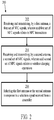
- Fig. 5 shows an illustrative embodiment of a detection process 500.
- the NFC controller may be searching for communication counterparts on all connected antennas. Detection methods like low-power card detection (LPCD) may be used, by means of which short RF sense pulses are transmitted, to detect load changes indicating the presence of counterparts.
- the poll interval timings can be set for each antenna independently. Once a counterpart is detected, communication with the counterpart or wireless charging of the counterpart can be initiated.
- An example of a poll interval with three polls for an NFC counterpart and one poll for a wireless charging counterpart per time interval is shown in Fig. 5 .
- the time interval may for example be one second.
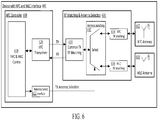
- Fig. 6 shows another illustrative embodiment of a communication device 600 with an NFC interface and a wireless charging interface.
- the communication device 600 comprises an NFC antenna 602 and a wireless charging antenna 604 which are operatively coupled to an RF matching and antenna selection unit 606.
- the RF matching and antenna selection unit 606 is operatively coupled to an NFC transceiver 620, which is comprised in an NFC controller 608.
- the RF matching and antenna selection unit 606 comprises a common part and an antenna-specific part.
- the antenna can be switched by means of a multiplexer comprised in an antenna switching block 612.
- the multiplexer received an antenna selection signal as an input; said antenna selection signal is provided by an NFC and wireless charging control unit 618 through an antenna selection interface 622.
- the RF modem transmission and reception connection can be commonly connected to the antennas (as shown in Fig. 6 ) or can be set independently (as shown in Fig. 7 ).
- the antenna selection unit may insert a low attenuation on the selected antenna. Furthermore, the antenna selection unit may terminate the unselected antenna or antennas with a predefined load impedance. It is noted that the presently disclosed concept can be expanded to support more than two antennas. This could be used to support different wireless charging antennas optimized for various accessories.
- the antenna selection interface may be a digital bus interface coding which antenna to be selected.
- the antenna selection unit can be implemented with various components, including metal-oxide-semiconductor (MOS) transistors, silicon-on-insulator (SOI) switches, RF switches and/or analog switches.
- MOS metal-oxide-semiconductor
- SOI silicon-on-insulator
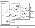
- Fig. 7 shows a further illustrative embodiment of a communication device 700 with an NFC interface and a wireless charging interface.
- the communication device 700 comprises components similar to those shown in Fig. 6 .
- the communication device 700 comprises an NFC antenna 702 and a wireless charging antenna 704 which are operatively coupled to an RF matching and antenna selection unit 706.
- the RF matching and antenna selection unit 706 is operatively coupled to an NFC transceiver 730, which is comprised in an NFC controller 708.
- the RF matching and antenna selection unit 706 comprises a common part and an antenna-specific part.
- the antenna can be switched by means of multiplexers comprised in an antenna switching block 714.
- the multiplexers receive an antenna selection signal as an input; said antenna selection signal is provided by an NFC and wireless charging control unit 728 through an antenna selection interface 732.
- the RF modem transmission and reception connections are set independently.
- Fig. 8 shows a further illustrative embodiment of a communication device 800 with an NFC interface and a wireless charging interface.
- a possible implementation is shown of the communication device shown in Fig. 6 .
- the communication device 800 comprises a single ended NFC antenna 802 and a wireless charging antenna 804 which are operatively coupled to an NFC RF matching circuit 806, respectively a wireless charging RF matching circuit 808.
- the NFC RF matching circuit 806 and wireless charging RF matching circuit 808 are operatively coupled to an antenna switching block 810, which is in turn operatively coupled to a common RF matching circuit 812.
- An NFC controller 814 is operatively coupled to both the common RF matching circuit 812 and the antenna switching block 810 and is configured to send control signals to the antenna switching block, in order to disable the NFC interface or the wireless charging interface.
- Fig. 8 shows a possible application circuit, which connects a single NFC controller 814 with a differential ended RF modem to an NFC antenna 802 and a wireless charging antenna 804.
- This example uses a single ended NFC antenna 802 and a differential ended wireless charging antenna 804.
- the presently disclosed device and method can be implemented using other types of antennas as well, i.e. both the NFC antenna and the wireless charging antenna can be single ended, or differential ended.
- a NFC controller is connected to a single antenna interconnect subblock (i.e., a common RF matching circuit), which is in turn connected to an antenna-specific antenna matching subblock.
- an antenna switching subblock 810 is added, in order to select only one active antenna from a set of two or more antennas.
- the antenna switching subblock 810 comprises a plurality of switches being configured to disconnect an unused antenna from the RF modem by connecting the relevant paths to ground potential.
- the switches can be implemented using RF switching devices which support electrical signal levels for NFC and wireless charging use cases (RF switches, NMOS transistors, etc.).
- Control signals DISABLE_NFC and DISABLE_WLC for the NFC controller enable the latter control the switches. More specifically, the switches of the antenna that should be disconnected can be closed, in order to short series capacitors C 0a or C 0b to ground.
- Control signals for the NFC controller enable the switches of the antenna to be disconnected to short series capacitors C 0a or C 0b to ground. This will put them in parallel to main EMC capacitor C 0 .
- DISABLE_NFC or DISABLE_WLC may be active, in order to connect only one antenna at a time to the RF modem.
Abstract
Description
- The present disclosure relates to a communication device. Furthermore, the present disclosure relates to a corresponding method for operating a communication device.
- Near field communication (NFC) is an established technology for proximity communication for various use cases. Using this technology, a primary device may generate a radio frequency (RF) field at a frequency of 13.56 MHz to power a secondary device. Modulation techniques are used to communicate in both directions. The secondary device may be a passive device (e.g. a tag or a transponder) or an active, typically battery-powered device. An RF field generated by an NFC reader can be used to charge the battery of the secondary device. This process is referred to as wireless charging. In such a scenario, the NFC communication channel may be used to control the charging operation.
- In accordance with a first aspect of the present disclosure, a communication device is provided, comprising: a first antenna configured to receive and transmit a first set of NFC signals, wherein said first set of NFC signals relates to NFC transactions; a second antenna configured to receive and transmit a second set of NFC signals, wherein said second set of NFC signals relates to wireless charging operations; a controller; and an antenna selection unit configured to select the first antenna or the second antenna in response to a selection signal received from said controller.
- In one or more embodiments, the device further comprises a radio frequency (RF) matching unit and an NFC transceiver which are operatively coupled to each other, wherein said RF matching unit comprises the antenna selection unit.
- In one or more embodiments, the antenna selection unit is configured to select the first antenna in a default condition.
- In one or more embodiments, the antenna selection unit comprises digital control interfaces for selecting the first antenna or the second antenna, wherein selecting the first antenna or the second antenna comprises connecting said first antenna and second antenna, respectively, to a transmitter and/or receiver of the communication device.
- In one or more embodiments, the antenna selection unit comprises a combined digital control interface for selecting the first antenna or the second antenna, wherein selecting the first antenna or second antenna comprises connecting said first antenna and second antenna, respectively, to both a transmitter and receiver of the communication device.
- In one or more embodiments, the antenna selection unit is configured to insert a low attenuation on a selected antenna path.
- In one or more embodiments, the antenna selection unit is configured to drive a predefined load impedance state of an unselected antenna path.
- In one or more embodiments, the controller is configured to generate the selection signal based on a result of a detection process.
- In one or more embodiments, the detection process comprises transmitting radio frequency (RF) pulses and/or RF polling commands through the first antenna or the second antenna, to detect the presence of an external communication device.
- In one or more embodiments, the RF pulses and/or RF polling commands are transmitted during configurable intervals.
- In one or more embodiments, transmitting the RF pulses and/or RF polling commands is repeated for a configurable number of times during said intervals.
- In one or more embodiments, the number of times is configurable for the first antenna and for the second antenna.
- In one or more embodiments, one or more signals of the second set of NFC signals transfer power to an external communication device.
- In one or more embodiments, the device comprises at least one further antenna, said further antenna being configured to receive and transmit a further set of NFC signals, wherein said further set of NFC signals relates to wireless charging operations, and wherein the antenna selection unit is configured to select the first antenna, the second antenna or the further antenna in response to the selection signal.
- In accordance with a second aspect of the present disclosure, a method for operating a communication device is conceived, the method comprising: receiving and transmitting, by a first antenna, a first set of NFC signals, wherein said first set of NFC signals relates to NFC transactions; receiving and transmitting, by a second antenna, a second set of NFC signals, wherein said second set of NFC signals relates to wireless charging operations; selecting the first antenna or the second antenna in response to a selection signal received from a controller.
- Embodiments will be described in more detail with reference to the appended drawings, in which:
-
Fig. 1 shows an illustrative embodiment of a communication device; -
Fig. 2 shows an illustrative embodiment of a method of operating a communication device; -
Fig. 3 shows an illustrative embodiment of an NFC-enabled device; -
Fig. 4 shows an illustrative embodiment of a communication device with an NFC interface and a wireless charging interface; -
Fig. 5 shows an illustrative embodiment of a detection process; -
Fig. 6 shows another illustrative embodiment of a communication device with an NFC interface and a wireless charging interface; -
Fig. 7 shows a further illustrative embodiment of a communication device with an NFC interface and a wireless charging interface; and -
Fig. 8 shows a further illustrative embodiment of a communication device with an NFC interface and a wireless charging interface. - Near field communication (NFC) is an established technology for proximity communication for various use cases. Using this technology, a primary device may generate a radio frequency (RF) field at a frequency of 13.56 MHz to power a secondary device. Modulation techniques are used to communicate in both directions. The secondary device may be a passive device (e.g. a tag or a transponder) or an active, typically battery-powered device. An RF field generated by an NFC reader can be used to charge the battery of the secondary device. This process is referred to as wireless charging. In such a scenario, the NFC communication channel may be used to control the charging operation.
- Typical implementations of NFC direct wireless charging make use of a WLC-P (wireless charging poller) device and a WLC-L (wireless charging listener) device. The wireless charging poller may be a standalone reader device which is configured to charge the battery of the wireless charging listener, i.e. a secondary accessory device like a watch or fitness tracker. The requirements for the antenna size and the placement of the antenna in wireless charging (WLC) use cases is often at odds with typical NFC use cases (such as NFC payment, ticketing, access or tag reading). Typical WLC accessory devices have a small form factor and require small WLC antenna sizes for a high-power efficiency. Thus, using a regular NFC antenna, such as an antenna used in a mobile phone, is typically not preferable. In other words, in addition to a regular NFC antenna, a reader (e.g., a mobile phone) should be equipped with a smaller antenna for wireless charging. In that case, the reader should then typically contain an additional controller, which increases the cost of the reader.
- Now discussed are a communication device and a corresponding method of operating a communication device, which facilitate the use of two or more different NFC antennas, specifically the use of antennas for regular NFC transactions and for wireless charging operations. Examples of regular NFC transactions include payment transactions and public transport ticket validations, which are carried out when an NFC-enabled mobile device (e.g., a phone) is within close proximity of an NFC-enabled terminal.
-
Fig. 1 shows an illustrative embodiment of acommunication device 100. Thecommunication device 100 comprises afirst antenna 102, asecond antenna 104, anantenna selection circuit 106 and acontroller 108. Thefirst antenna 102 is configured to receive and transmit a first set of NFC signals relating to NFC transactions, and thesecond antenna 104 is configured to receive and transmit a second set of NFC signals relating to wireless charging operations. Furthermore, the antenna selection unit is configured to select the first antenna or the second antenna in response to a selection signal received from the controller. In this way, the use of two or more different NFC antennas can be facilitated. -
Fig. 2 shows an illustrative embodiment of amethod 200 of operating a communication device. Themethod 200 comprises, at 202, receiving and transmitting, by a first antenna, a first set of NFC signals, wherein said first set of NFC signals relates to NFC transactions. Furthermore, themethod 200 comprises, at 204, receiving and transmitting, by a second antenna, a second set of NFC signals, wherein said second set of NFC signals relates to wireless charging operations. Finally, themethod 200 comprises, at 206, selecting the first antenna or the second antenna in response to a selection signal received from a controller. - In a practical implementation, the communication device further comprises a radio frequency (RF) matching unit and an NFC transceiver which are operatively coupled to each other, wherein the RF matching unit comprises the antenna selection unit. Furthermore, in one or more embodiments, the antenna selection unit is configured to select the first antenna in a default condition. In this way, NFC transactions may be performed as quickly as possible. In a practical implementation, the antenna selection unit comprises digital control interfaces for selecting the first antenna or the second antenna, wherein selecting the first antenna or the second antenna comprises connecting said first antenna and second antenna, respectively, to a transmitter and/or receiver of the communication device. In an alternative practical implementation, the antenna selection unit comprises a combined digital control interface for selecting the first antenna or the second antenna, wherein selecting the first antenna or second antenna comprises connecting said first antenna and second antenna, respectively, to both a transmitter and receiver of the communication device.
- In one or more embodiments, the antenna selection unit is configured to insert a low attenuation on a selected antenna path. In this way, a good power efficiency may be achieved from the transmitter to the antenna. More specifically, the consumed transmit power should primarily be used to generate the radio frequency field and not be dissipated within the matching and switching circuitry. By inserting a low attenuation on the selected antenna path, such dissipation may be avoided. The skilled person will appreciate that this feature may be realized by a proper choice of the matching topology and switching circuitry and a proper selection of a switching component. For example, the on-resistance of a switch should be low to achieve a low attenuation.
- In one or more embodiments, the antenna selection unit is configured to drive a predefined load impedance state of an unselected antenna path. In this way, a deterministic detection sensitivity may be achieved. More specifically, the unselected antenna may form part of a radio frequency field detection network. By driving a predefined load impedance state of the unselected antenna path, the detection sensitivity of the network may become deterministic. The skilled person will appreciate that this feature may be realized by a proper choice of the matching topology, for example a proper placement of a switching component.
- In one or more embodiments, the controller may be configured to generate the selection signal based on a result of a detection process. In particular, the detection process may be used to detect the presence of an external communication device in proximity of the first antenna and/or the second antenna. In this way, the first antenna and/or second antenna can quickly be selected, to start performing transactions and/or operations through said antenna without a significant delay. The detection process may comprise transmitting RF pulses - for example using low-power card detection (LPCD) techniques - and/or RF polling commands through the first antenna or the second antenna, to detect the presence of an external communication device. This results in practical implementation. Furthermore, the use of RF pulses facilitates reducing the power consumption of the communication device. In one or more embodiments, the RF pulses and/or polling commands are transmitted during configurable intervals. Furthermore, transmitting the RF pulses and/or RF polling commands may be repeated for a configurable number of times during said intervals. In particular, said number of times may be configurable for the first antenna and for the second antenna. In other words, the number of times the RF pulses or polling commands are repeated within a given interval can be different for the first antenna and second antenna. In this way, the flexibility of the detection process may be increased. For instance, a higher priority may be given to detecting external communication devices either through the first antenna or through the second antenna. Furthermore, one or more signals of the second set of NFC signals may transfer power to an external communication device. In this way, the second antenna may effectively be used for a wireless transfer of power to an external device to be charged.
- It is noted that the communication device may include more than two antennas, for example an antenna for performing regular NFC transactions and a plurality of antennas for charging different types of external communication devices. In this way, the system can be extended to cover various use cases. Thus, in one or more embodiments, the communication device comprises at least one further antenna, said further antenna being configured to receive and transmit a further set of NFC signals, wherein said further set of NFC signals relates to wireless charging operations, and the antenna selection unit is configured to select the first antenna, the second antenna or the further antenna in response to the selection signal.
-
Fig. 3 shows an illustrative embodiment of an NFC-enableddevice 300. The NFC-enableddevice 300 comprises a first antenna, i.e. anNFC antenna 302 for carrying out regular NFC transactions and a second antenna, i.e. awireless charging antenna 304 for carrying out wireless charging operations. The second antenna may be an NFC antenna that is specifically designed for wireless charging operations, having a smaller form factor than a regular NFC antenna. In accordance with the present disclosure, a single NFC controller may be connected to NFC and wireless charging (WLC) antennas. Furthermore, device detection may be performed on the different links, i.e. through the different antennas. This allows a mobile device, such as a mobile phone, to support regular NFC use cases as well as WLC poller use cases with optimized WLC antennas. Furthermore, in accordance with the present disclosure, antenna switching concepts with combined and separated links for transmission and reception interface may be conceived. In particular, a single primary NFC device may be operated in a time-multiplexed manner, for supporting regular NFC use cases on an NFC antenna and for supporting wireless charging use cases on at least one second WLC antenna. This allows adding WLC use cases to mobile devices with NFC support without adding an additional NFC controller and allows to control RF concurrency between both RF antenna links. A detection process may be carried out to detect a counterpart device on one or the other RF link. -
Fig. 4 shows an illustrative embodiment of acommunication device 400 with an NFC interface and a wireless charging interface. Thedevice 400 comprises anNFC antenna 402 and awireless charging antenna 404, both of which are operatively coupled to an RF matching andantenna selection unit 406. The RF matching andantenna selection unit 406 is operatively connected to anNFC transceiver unit 410, which is included in anNFC controller 408 of thedevice 400. In accordance with the present disclosure, the RF matching andantenna selection unit 406 is configured to select theNFC antenna 402 or thewireless charging antenna 404 in response to an antenna selection signal received from theNFC controller 408. In particular, the RF modem (i.e., the NFC transceiver 410) of theNFC controller 408 is connected to a combined RF matching circuit for both antennas. A selection interface may define which antenna is connected to the RF modem. The default selection may be to connect theNFC antenna 402 to the NFC controller 408 (to enable regular NFC use cases). During a detection process for detecting an external device to be charged, as well as during a wireless charging operation, thewireless charging antenna 404 is connected to the RF modem. -
Fig. 5 shows an illustrative embodiment of adetection process 500. During a device detection phase, the NFC controller may be searching for communication counterparts on all connected antennas. Detection methods like low-power card detection (LPCD) may be used, by means of which short RF sense pulses are transmitted, to detect load changes indicating the presence of counterparts. The poll interval timings can be set for each antenna independently. Once a counterpart is detected, communication with the counterpart or wireless charging of the counterpart can be initiated. An example of a poll interval with three polls for an NFC counterpart and one poll for a wireless charging counterpart per time interval is shown inFig. 5 . The time interval may for example be one second. -
Fig. 6 shows another illustrative embodiment of acommunication device 600 with an NFC interface and a wireless charging interface. Thecommunication device 600 comprises anNFC antenna 602 and awireless charging antenna 604 which are operatively coupled to an RF matching andantenna selection unit 606. The RF matching andantenna selection unit 606 is operatively coupled to anNFC transceiver 620, which is comprised in anNFC controller 608. The RF matching andantenna selection unit 606 comprises a common part and an antenna-specific part. The antenna can be switched by means of a multiplexer comprised in anantenna switching block 612. The multiplexer received an antenna selection signal as an input; said antenna selection signal is provided by an NFC and wireless chargingcontrol unit 618 through an antenna selection interface 622. The RF modem transmission and reception connection can be commonly connected to the antennas (as shown inFig. 6 ) or can be set independently (as shown inFig. 7 ). The antenna selection unit may insert a low attenuation on the selected antenna. Furthermore, the antenna selection unit may terminate the unselected antenna or antennas with a predefined load impedance. It is noted that the presently disclosed concept can be expanded to support more than two antennas. This could be used to support different wireless charging antennas optimized for various accessories. The antenna selection interface may be a digital bus interface coding which antenna to be selected. The antenna selection unit can be implemented with various components, including metal-oxide-semiconductor (MOS) transistors, silicon-on-insulator (SOI) switches, RF switches and/or analog switches. -
Fig. 7 shows a further illustrative embodiment of acommunication device 700 with an NFC interface and a wireless charging interface. Thecommunication device 700 comprises components similar to those shown inFig. 6 . Thecommunication device 700 comprises anNFC antenna 702 and awireless charging antenna 704 which are operatively coupled to an RF matching andantenna selection unit 706. The RF matching andantenna selection unit 706 is operatively coupled to anNFC transceiver 730, which is comprised in anNFC controller 708. The RF matching andantenna selection unit 706 comprises a common part and an antenna-specific part. The antenna can be switched by means of multiplexers comprised in anantenna switching block 714. The multiplexers receive an antenna selection signal as an input; said antenna selection signal is provided by an NFC and wireless chargingcontrol unit 728 through anantenna selection interface 732. The RF modem transmission and reception connections are set independently. -
Fig. 8 shows a further illustrative embodiment of acommunication device 800 with an NFC interface and a wireless charging interface. In particular, a possible implementation is shown of the communication device shown inFig. 6 . It is noted that the presently disclosed device and method are not limited to this implementation. In particular, the skilled person will appreciate that other implementations are possible too, either based on the communication device shown inFig. 6 or the communication device shown inFig. 7 . Thecommunication device 800 comprises a single endedNFC antenna 802 and awireless charging antenna 804 which are operatively coupled to an NFCRF matching circuit 806, respectively a wireless chargingRF matching circuit 808. The NFCRF matching circuit 806 and wireless chargingRF matching circuit 808 are operatively coupled to anantenna switching block 810, which is in turn operatively coupled to a commonRF matching circuit 812. AnNFC controller 814 is operatively coupled to both the commonRF matching circuit 812 and theantenna switching block 810 and is configured to send control signals to the antenna switching block, in order to disable the NFC interface or the wireless charging interface. - In particular,
Fig. 8 shows a possible application circuit, which connects asingle NFC controller 814 with a differential ended RF modem to anNFC antenna 802 and awireless charging antenna 804. This example uses a single endedNFC antenna 802 and a differential endedwireless charging antenna 804. However, it is noted that the presently disclosed device and method can be implemented using other types of antennas as well, i.e. both the NFC antenna and the wireless charging antenna can be single ended, or differential ended. Typically, a NFC controller is connected to a single antenna interconnect subblock (i.e., a common RF matching circuit), which is in turn connected to an antenna-specific antenna matching subblock. In accordance with the present disclosure, anantenna switching subblock 810 is added, in order to select only one active antenna from a set of two or more antennas. Theantenna switching subblock 810 comprises a plurality of switches being configured to disconnect an unused antenna from the RF modem by connecting the relevant paths to ground potential. The switches can be implemented using RF switching devices which support electrical signal levels for NFC and wireless charging use cases (RF switches, NMOS transistors, etc.). Control signals DISABLE_NFC and DISABLE_WLC for the NFC controller enable the latter control the switches. More specifically, the switches of the antenna that should be disconnected can be closed, in order to short series capacitors C0a or C0b to ground. Control signals for the NFC controller enable the switches of the antenna to be disconnected to short series capacitors C0a or C0b to ground. This will put them in parallel to main EMC capacitor C0. Thus, either DISABLE_NFC or DISABLE_WLC may be active, in order to connect only one antenna at a time to the RF modem. - It is noted that the embodiments above have been described with reference to different subject-matters. In particular, some embodiments may have been described with reference to method-type claims whereas other embodiments may have been described with reference to apparatus-type claims. However, a person skilled in the art will gather from the above that, unless otherwise indicated, in addition to any combination of features belonging to one type of subject-matter also any combination of features relating to different subject-matters, in particular a combination of features of the method-type claims and features of the apparatus-type claims, is considered to be disclosed with this document.
- Furthermore, it is noted that the drawings are schematic. In different drawings, similar or identical elements are provided with the same reference signs. Furthermore, it is noted that in an effort to provide a concise description of the illustrative embodiments, implementation details which fall into the customary practice of the skilled person may not have been described. It should be appreciated that in the development of any such implementation, as in any engineering or design project, numerous implementation-specific decisions must be made in order to achieve the developers' specific goals, such as compliance with system-related and business-related constraints, which may vary from one implementation to another. Moreover, it should be appreciated that such a development effort might be complex and time consuming, but would nevertheless be a routine undertaking of design, fabrication, and manufacture for those of ordinary skill.
- Finally, it is noted that the skilled person will be able to design many alternative embodiments without departing from the scope of the appended claims. In the claims, any reference sign placed between parentheses shall not be construed as limiting the claim. The word "comprise(s)" or "comprising" does not exclude the presence of elements or steps other than those listed in a claim. The word "a" or "an" preceding an element does not exclude the presence of a plurality of such elements. Measures recited in the claims may be implemented by means of hardware comprising several distinct elements and/or by means of a suitably programmed processor. In a device claim enumerating several means, several of these means may be embodied by one and the same item of hardware. The mere fact that certain measures are recited in mutually different dependent claims does not indicate that a combination of these measures cannot be used to advantage.
-
- 100
- communication device
- 102
- first antenna
- 104
- second antenna
- 106
- antenna selection circuit
- 108
- controller
- 200
- method operating a communication device
- 202
- receiving and transmitting, by a first antenna, a first set of NFC signals, wherein said first set of NFC signals relates to NFC transactions
- 204
- receiving and transmitting, by a second antenna, a second set of NFC signals, wherein said second set of NFC signals relates to wireless charging operations;
- 206
- selecting the first antenna or the second antenna in response to a selection signal received from a controller
- 300
- NFC-enabled device
- 302
- near field communication antenna
- 304
- wireless charging antenna
- 400
- communication device with NFC interface and wireless charging interface
- 402
- NFC antenna
- 404
- wireless charging antenna
- 406
- RF matching and antenna selection unit
- 408
- NFC controller
- 410
- NFC transceiver
- 500
- detection process
- 600
- communication device with NFC interface and wireless charging interface
- 602
- NFC antenna
- 604
- wireless charging antenna
- 606
- RF matching and antenna selection unit
- 608
- NFC controller
- 610
- common transmitter and receiver RF matching circuit
- 612
- antenna switching block
- 614
- NFC RF matching circuit
- 616
- wireless charging RF matching circuit
- 618
- NFC and wireless charging control unit
- 620
- NFC transceiver
- 622
- antenna selection interface
- 700
- communication device with NFC interface and wireless charging interface
- 702
- NFC antenna
- 704
- wireless charging antenna
- 706
- RF matching and antenna selection unit
- 708
- NFC controller
- 710
- common transmitter RF matching circuit
- 712
- common receiver RF matching circuit
- 714
- antenna switching block
- 716
- NFC transmitter RF matching circuit
- 718
- wireless charging transmitter RF matching circuit
- 720
- NFC receiver RF matching circuit
- 722
- wireless charging receiver RF matching circuit
- 724
- NFC antenna combiner
- 726
- wireless charging antenna combiner
- 800
- communication device with NFC interface and wireless charging interface
- 802
- NFC single ended antenna
- 804
- NFC wireless charging antenna
- 806
- NFC RF matching circuit
- 808
- wireless charging RF matching circuit
- 810
- antenna switching block
- 812
- common RF matching circuit
- 814
- NFC controller
Claims (15)
- A communication device, comprising:a first antenna configured to receive and transmit a first set of NFC signals, wherein said first set of NFC signals relates to NFC transactions;a second antenna configured to receive and transmit a second set of NFC signals, wherein said second set of NFC signals relates to wireless charging operations;a controller; andan antenna selection unit configured to select the first antenna or the second antenna in response to a selection signal received from said controller.
- The device of claim 1, further comprising a radio frequency, RF, matching unit and an NFC transceiver which are operatively coupled to each other, and wherein said RF matching unit comprises the antenna selection unit.
- The device of claim 1 or 2, wherein the antenna selection unit is configured to select the first antenna in a default condition.
- The device of any preceding claim, wherein the antenna selection unit comprises digital control interfaces for selecting the first antenna or the second antenna, wherein selecting the first antenna or the second antenna comprises connecting said first antenna and second antenna, respectively, to a transmitter and/or receiver of the communication device.
- The device of any one of claims 1 to 3, wherein the antenna selection unit comprises a combined digital control interface for selecting the first antenna or the second antenna, wherein selecting the first antenna or second antenna comprises connecting said first antenna and second antenna, respectively, to both a transmitter and receiver of the communication device.
- The device of any preceding claim, wherein the antenna selection unit is configured to insert a low attenuation on a selected antenna path.
- The device of any preceding claim, wherein the antenna selection unit is configured to drive a predefined load impedance state of an unselected antenna path.
- The device of any preceding claim, wherein the controller is configured to generate the selection signal based on a result of a detection process.
- The device of any preceding claim, wherein the detection process comprises transmitting radio frequency, RF, pulses and/or RF polling commands through the first antenna or the second antenna, to detect the presence of an external communication device.
- The device of claim 9, wherein the RF pulses and/or RF polling commands are transmitted during configurable intervals.
- The device of claim 10, wherein transmitting the RF pulses and/or RF polling commands is repeated for a configurable number of times during said intervals.
- The device of claim 11, wherein the number of times is configurable for the first antenna and for the second antenna.
- The device of any preceding claim, wherein one or more signals of the second set of NFC signals transfer power to an external communication device.
- The device of any preceding claim, comprising at least one further antenna, said further antenna being configured to receive and transmit a further set of NFC signals, wherein said further set of NFC signals relates to wireless charging operations, and wherein the antenna selection unit is configured to select the first antenna, the second antenna or the further antenna in response to the selection signal.
- A method for operating a communication device, comprising:receiving and transmitting, by a first antenna, a first set of NFC signals, wherein said first set of NFC signals relates to NFC transactions;receiving and transmitting, by a second antenna, a second set of NFC signals, wherein said second set of NFC signals relates to wireless charging operations;selecting the first antenna or the second antenna in response to a selection signal received from a controller.
Priority Applications (3)
| Application Number | Priority Date | Filing Date | Title |
|---|---|---|---|
| EP20156033.1A EP3863185A1 (en) | 2020-02-07 | 2020-02-07 | Communication device and method for operating the same |
| CN202110055930.7A CN113258960A (en) | 2020-02-07 | 2021-01-15 | Communication device and operation method thereof |
| US17/158,081 US11411611B2 (en) | 2020-02-07 | 2021-01-26 | Communication device and method for operating the same |
Applications Claiming Priority (1)
| Application Number | Priority Date | Filing Date | Title |
|---|---|---|---|
| EP20156033.1A EP3863185A1 (en) | 2020-02-07 | 2020-02-07 | Communication device and method for operating the same |
Publications (1)
| Publication Number | Publication Date |
|---|---|
| EP3863185A1 true EP3863185A1 (en) | 2021-08-11 |
Family
ID=69526158
Family Applications (1)
| Application Number | Title | Priority Date | Filing Date |
|---|---|---|---|
| EP20156033.1A Pending EP3863185A1 (en) | 2020-02-07 | 2020-02-07 | Communication device and method for operating the same |
Country Status (3)
| Country | Link |
|---|---|
| US (1) | US11411611B2 (en) |
| EP (1) | EP3863185A1 (en) |
| CN (1) | CN113258960A (en) |
Families Citing this family (2)
| Publication number | Priority date | Publication date | Assignee | Title |
|---|---|---|---|---|
| KR20220062381A (en) * | 2019-09-16 | 2022-05-16 | 스냅 인코포레이티드 | Wireless communication device for RF charging enclosures |
| CN114863599A (en) * | 2022-04-07 | 2022-08-05 | 华南师范大学 | Access control system based on RFID and NB-IoT and control method thereof |
Citations (4)
| Publication number | Priority date | Publication date | Assignee | Title |
|---|---|---|---|---|
| US20080272889A1 (en) * | 2005-01-19 | 2008-11-06 | Innovision Research & Technology Plc | Nfc Communicators and Nfc Communications Enabled Devices |
| US20120149301A1 (en) * | 2010-12-13 | 2012-06-14 | Qualcomm Incorporated | Receiver for near field communication and wireless power functionalities |
| EP2683090A2 (en) * | 2012-07-03 | 2014-01-08 | Samsung Electronics Co., Ltd | Apparatus and method for operating antennas |
| EP3280005A1 (en) * | 2016-08-04 | 2018-02-07 | Samsung Electronics Co., Ltd. | Electronic device including shielding structure |
Family Cites Families (26)
| Publication number | Priority date | Publication date | Assignee | Title |
|---|---|---|---|---|
| US8238823B2 (en) * | 2005-02-09 | 2012-08-07 | Nxp B.V. | Method for ensuring a secure NFC functionality of a wireless mobile communication device and wireless mobile communication device having a secure NFC functionality |
| US9240824B2 (en) * | 2009-02-13 | 2016-01-19 | Qualcomm Incorporated | Wireless power and wireless communication for electronic devices |
| US10079090B2 (en) * | 2010-12-01 | 2018-09-18 | Triune Systems, LLC | Multiple coil data transmission system |
| KR101265234B1 (en) * | 2012-01-30 | 2013-05-16 | 쓰리에이로직스(주) | Nfc device |
| EP3012981B1 (en) * | 2012-03-15 | 2019-11-13 | Intel Corporation | Near field communication (nfc) and proximity sensor for portable devices |
| KR101192665B1 (en) * | 2012-04-03 | 2012-10-19 | 주식회사 맥스웨이브 | Mobile device using a common antenna for near field communication and wireless charging |
| KR20140112231A (en) * | 2013-03-13 | 2014-09-23 | 삼성전자주식회사 | Apparatus and method for connecting an antenna of a near field communication in a portable terminal |
| US20140347232A1 (en) * | 2013-05-21 | 2014-11-27 | Alireza Mahanfar | Electronic device components as antennas |
| CN104319830B (en) * | 2014-10-09 | 2017-02-01 | 深圳市安普盛科技有限公司 | Near field communication (NFC)-based charging system and method |
| KR102324342B1 (en) | 2014-12-24 | 2021-11-10 | 삼성에스디아이 주식회사 | Battery pack with wireless charging and near field communication functions |
| KR102276841B1 (en) * | 2015-01-14 | 2021-07-14 | 삼성전자주식회사 | Antenna device and control method thereof |
| KR101594380B1 (en) * | 2015-03-04 | 2016-02-16 | 엘지전자 주식회사 | Mobile terminal and coil antenna moduel |
| TWM508155U (en) | 2015-06-10 | 2015-09-01 | Jogtek Corp | Near field communication wireless charging apparatus |
| CN105262513B (en) * | 2015-09-17 | 2019-02-05 | 王清斌 | A kind of NFC active communication interface with high transmitting power |
| WO2017062647A1 (en) | 2015-10-06 | 2017-04-13 | Witricity Corporation | Rfid tag and transponder detection in wireless energy transfer systems |
| KR102440975B1 (en) * | 2016-01-21 | 2022-09-07 | 삼성전자주식회사 | Electronic device and method for short range wireless communication in the electronic device |
| KR102548688B1 (en) * | 2016-03-28 | 2023-06-28 | 삼성전자주식회사 | Processing method for leakage power and electronic device supporting the same |
| US10461812B2 (en) * | 2016-04-01 | 2019-10-29 | Nan Jing Qiwei Technology Limited | Near-field communication (NFC) tags optimized for high performance NFC and wireless power reception with small antennas |
| KR101846953B1 (en) * | 2016-04-06 | 2018-04-09 | 주식회사 맵스 | Communication apparatus and electronic device having the protection function from wireless recharging |
| CN107547103A (en) | 2016-12-23 | 2018-01-05 | 西安闻泰电子科技有限公司 | NFC and wireless charging common antenna system and method |
| KR102381435B1 (en) * | 2017-10-30 | 2022-03-31 | 삼성전자주식회사 | Antenna for electromagnetic interference detection and portable electronic device including the same |
| CN108075231A (en) * | 2017-12-28 | 2018-05-25 | 广州土圭垚信息科技有限公司 | A kind of antenna module and terminal device |
| KR102564363B1 (en) * | 2018-07-27 | 2023-08-08 | 삼성전자 주식회사 | Electronic device for controlling a communication channel associated with wireless charging based on identification information received from external device and methd for the same |
| KR102541839B1 (en) * | 2018-07-31 | 2023-06-09 | 삼성전자 주식회사 | Electronic device having a plurality of stacked coil antennas |
| US10997483B2 (en) * | 2019-06-12 | 2021-05-04 | Stmicroelectronics, Inc | NFC antenna switch |
| EP3890196B1 (en) | 2020-04-03 | 2023-06-21 | Nxp B.V. | Communication and wireless charging device and operating method |
-
2020
- 2020-02-07 EP EP20156033.1A patent/EP3863185A1/en active Pending
-
2021
- 2021-01-15 CN CN202110055930.7A patent/CN113258960A/en active Pending
- 2021-01-26 US US17/158,081 patent/US11411611B2/en active Active
Patent Citations (4)
| Publication number | Priority date | Publication date | Assignee | Title |
|---|---|---|---|---|
| US20080272889A1 (en) * | 2005-01-19 | 2008-11-06 | Innovision Research & Technology Plc | Nfc Communicators and Nfc Communications Enabled Devices |
| US20120149301A1 (en) * | 2010-12-13 | 2012-06-14 | Qualcomm Incorporated | Receiver for near field communication and wireless power functionalities |
| EP2683090A2 (en) * | 2012-07-03 | 2014-01-08 | Samsung Electronics Co., Ltd | Apparatus and method for operating antennas |
| EP3280005A1 (en) * | 2016-08-04 | 2018-02-07 | Samsung Electronics Co., Ltd. | Electronic device including shielding structure |
Also Published As
| Publication number | Publication date |
|---|---|
| US20210250064A1 (en) | 2021-08-12 |
| CN113258960A (en) | 2021-08-13 |
| US11411611B2 (en) | 2022-08-09 |
Similar Documents
| Publication | Publication Date | Title |
|---|---|---|
| US10887847B2 (en) | Active antenna system, mobile terminal, and configuration method of antenna system | |
| CN105099414B (en) | TX/RX based on RF transformers integrates RF switches | |
| US8725088B2 (en) | Antenna solution for near-field and far-field communication in wireless devices | |
| EP1897231B1 (en) | Device, module and method for shared antenna operation in a rfid technology based communication environment | |
| CN101926096A (en) | Integrated antenna array and RF front end module | |
| CN103703689B (en) | Use the front end with High Linear and low-loss pin diode switch being used for simultaneously transmitting | |
| CN108988877A (en) | Radio frequency system, antenna switching control method and Related product | |
| US11411611B2 (en) | Communication device and method for operating the same | |
| US8543059B2 (en) | Combo wireless system and method using the same | |
| CN108199728A (en) | Multidiameter option switch, radio frequency system and wireless telecom equipment | |
| CN104247286B (en) | Wireless docking link budget optimizes system | |
| US20140349572A1 (en) | Integrated inductive power receiver and near field communicator | |
| US20070123174A1 (en) | Device and method for single connector access to multiple transceivers | |
| EP2600537B1 (en) | Apparatus and method for providing diversity service antenna in portable terminal | |
| CN101019334A (en) | Zero power radio | |
| CN109980759B (en) | Method for managing contactless communication and contactless charging within a system and corresponding system | |
| US11784681B2 (en) | Communication device and operating method | |
| EP4064760A1 (en) | Device control method and apparatus, storage medium and electronic device | |
| CN111669199A (en) | Power detection circuit and electronic equipment | |
| CN106933762A (en) | Internal serial interface | |
| EP2947785B1 (en) | Pru short beacon detection | |
| CN109560837A (en) | For operating the method and system of the communication device communicated by inductive coupling | |
| US11038553B2 (en) | EMC inductor-free RF front-end method and topology with power by field function for an inductively coupled communication system | |
| US20130203355A1 (en) | Short-distance wireless communication device | |
| CN105703804B (en) | The data rate or range of near-field communication are improved using difference coil topology |
Legal Events
| Date | Code | Title | Description |
|---|---|---|---|
| PUAI | Public reference made under article 153(3) epc to a published international application that has entered the european phase |
Free format text: ORIGINAL CODE: 0009012 |
|
| STAA | Information on the status of an ep patent application or granted ep patent |
Free format text: STATUS: THE APPLICATION HAS BEEN PUBLISHED |
|
| AK | Designated contracting states |
Kind code of ref document: A1 Designated state(s): AL AT BE BG CH CY CZ DE DK EE ES FI FR GB GR HR HU IE IS IT LI LT LU LV MC MK MT NL NO PL PT RO RS SE SI SK SM TR |
|
| STAA | Information on the status of an ep patent application or granted ep patent |
Free format text: STATUS: REQUEST FOR EXAMINATION WAS MADE |
|
| 17P | Request for examination filed |
Effective date: 20220211 |
|
| RBV | Designated contracting states (corrected) |
Designated state(s): AL AT BE BG CH CY CZ DE DK EE ES FI FR GB GR HR HU IE IS IT LI LT LU LV MC MK MT NL NO PL PT RO RS SE SI SK SM TR |
|
| STAA | Information on the status of an ep patent application or granted ep patent |
Free format text: STATUS: EXAMINATION IS IN PROGRESS |
|
| 17Q | First examination report despatched |
Effective date: 20230613 |