EP3861958A1 - Support arm joint device and support system for a medical device - Google Patents
Support arm joint device and support system for a medical device Download PDFInfo
- Publication number
- EP3861958A1 EP3861958A1 EP20155980.4A EP20155980A EP3861958A1 EP 3861958 A1 EP3861958 A1 EP 3861958A1 EP 20155980 A EP20155980 A EP 20155980A EP 3861958 A1 EP3861958 A1 EP 3861958A1
- Authority
- EP
- European Patent Office
- Prior art keywords
- support arm
- joint device
- spring
- arm joint
- fastening element
- Prior art date
- Legal status (The legal status is an assumption and is not a legal conclusion. Google has not performed a legal analysis and makes no representation as to the accuracy of the status listed.)
- Withdrawn
Links
Images


Classifications
-
- A—HUMAN NECESSITIES
- A61—MEDICAL OR VETERINARY SCIENCE; HYGIENE
- A61B—DIAGNOSIS; SURGERY; IDENTIFICATION
- A61B34/00—Computer-aided surgery; Manipulators or robots specially adapted for use in surgery
- A61B34/30—Surgical robots
-
- A—HUMAN NECESSITIES
- A61—MEDICAL OR VETERINARY SCIENCE; HYGIENE
- A61B—DIAGNOSIS; SURGERY; IDENTIFICATION
- A61B34/00—Computer-aided surgery; Manipulators or robots specially adapted for use in surgery
- A61B34/70—Manipulators specially adapted for use in surgery
-
- A—HUMAN NECESSITIES
- A61—MEDICAL OR VETERINARY SCIENCE; HYGIENE
- A61B—DIAGNOSIS; SURGERY; IDENTIFICATION
- A61B90/00—Instruments, implements or accessories specially adapted for surgery or diagnosis and not covered by any of the groups A61B1/00 - A61B50/00, e.g. for luxation treatment or for protecting wound edges
- A61B90/50—Supports for surgical instruments, e.g. articulated arms
-
- F—MECHANICAL ENGINEERING; LIGHTING; HEATING; WEAPONS; BLASTING
- F16—ENGINEERING ELEMENTS AND UNITS; GENERAL MEASURES FOR PRODUCING AND MAINTAINING EFFECTIVE FUNCTIONING OF MACHINES OR INSTALLATIONS; THERMAL INSULATION IN GENERAL
- F16M—FRAMES, CASINGS OR BEDS OF ENGINES, MACHINES OR APPARATUS, NOT SPECIFIC TO ENGINES, MACHINES OR APPARATUS PROVIDED FOR ELSEWHERE; STANDS; SUPPORTS
- F16M13/00—Other supports for positioning apparatus or articles; Means for steadying hand-held apparatus or articles
- F16M13/02—Other supports for positioning apparatus or articles; Means for steadying hand-held apparatus or articles for supporting on, or attaching to, an object, e.g. tree, gate, window-frame, cycle
- F16M13/022—Other supports for positioning apparatus or articles; Means for steadying hand-held apparatus or articles for supporting on, or attaching to, an object, e.g. tree, gate, window-frame, cycle repositionable
-
- A—HUMAN NECESSITIES
- A61—MEDICAL OR VETERINARY SCIENCE; HYGIENE
- A61B—DIAGNOSIS; SURGERY; IDENTIFICATION
- A61B34/00—Computer-aided surgery; Manipulators or robots specially adapted for use in surgery
- A61B34/30—Surgical robots
- A61B2034/305—Details of wrist mechanisms at distal ends of robotic arms
-
- A—HUMAN NECESSITIES
- A61—MEDICAL OR VETERINARY SCIENCE; HYGIENE
- A61B—DIAGNOSIS; SURGERY; IDENTIFICATION
- A61B90/00—Instruments, implements or accessories specially adapted for surgery or diagnosis and not covered by any of the groups A61B1/00 - A61B50/00, e.g. for luxation treatment or for protecting wound edges
- A61B90/06—Measuring instruments not otherwise provided for
- A61B2090/064—Measuring instruments not otherwise provided for for measuring force, pressure or mechanical tension
-
- A—HUMAN NECESSITIES
- A61—MEDICAL OR VETERINARY SCIENCE; HYGIENE
- A61B—DIAGNOSIS; SURGERY; IDENTIFICATION
- A61B90/00—Instruments, implements or accessories specially adapted for surgery or diagnosis and not covered by any of the groups A61B1/00 - A61B50/00, e.g. for luxation treatment or for protecting wound edges
- A61B90/50—Supports for surgical instruments, e.g. articulated arms
- A61B2090/508—Supports for surgical instruments, e.g. articulated arms with releasable brake mechanisms
-
- F—MECHANICAL ENGINEERING; LIGHTING; HEATING; WEAPONS; BLASTING
- F16—ENGINEERING ELEMENTS AND UNITS; GENERAL MEASURES FOR PRODUCING AND MAINTAINING EFFECTIVE FUNCTIONING OF MACHINES OR INSTALLATIONS; THERMAL INSULATION IN GENERAL
- F16M—FRAMES, CASINGS OR BEDS OF ENGINES, MACHINES OR APPARATUS, NOT SPECIFIC TO ENGINES, MACHINES OR APPARATUS PROVIDED FOR ELSEWHERE; STANDS; SUPPORTS
- F16M2200/00—Details of stands or supports
- F16M2200/04—Balancing means
- F16M2200/047—Balancing means for balancing translational movement of the head
-
- F—MECHANICAL ENGINEERING; LIGHTING; HEATING; WEAPONS; BLASTING
- F16—ENGINEERING ELEMENTS AND UNITS; GENERAL MEASURES FOR PRODUCING AND MAINTAINING EFFECTIVE FUNCTIONING OF MACHINES OR INSTALLATIONS; THERMAL INSULATION IN GENERAL
- F16M—FRAMES, CASINGS OR BEDS OF ENGINES, MACHINES OR APPARATUS, NOT SPECIFIC TO ENGINES, MACHINES OR APPARATUS PROVIDED FOR ELSEWHERE; STANDS; SUPPORTS
- F16M2200/00—Details of stands or supports
- F16M2200/06—Arms
- F16M2200/068—Arms being part of the undercarriage
Definitions
- the present invention relates to a support arm joint device for a support system for holding at least one medical device and a support system for a medical device.
- Support arm systems are used, for example, in operating theaters for locally displaceable holding of a medical device or device.
- a support arm can be movably anchored to a ceiling, a wall or a floor by means of a bearing arrangement for this purpose. It can also be attached to a frame with rollers.
- a support system with at least one support arm can also be referred to as a support arm system and a support system which is designed to hold medical devices can also be referred to as a medical support system.
- Support systems usually have at least one axis of movement so that the medical device held, which is also referred to as a medical device and can have, for example, an operating lamp, a monitor, examination devices, one or more injectors, surgical instruments or dental drills, in accordance with the respective requirements can be moved.
- the mounting that enables the movement can also be referred to as a joint device or a support arm joint device, it also being possible for this to include a support arm.
- the medical device can be brought into a comfortable and safe position for carrying out the respective medical procedures and monitoring.
- the local relocation of medical devices is essential in many medical procedures in order to facilitate the work of the medical staff or to enable them at all.
- a lever arm By pivoting a support arm, however, a lever arm can be changed with regard to its mounting.
- the support arm is pivoted about an essentially horizontal axis, as a result of which the height of the medical device held thereon can be changed, the weight of the medical device becomes a lever arm changed compared to the attachment or storage of the support arm. Nevertheless, it is desirable for the medical device to remain in a position set by pivoting the support arm.
- Spring-balanced support arms or support arm joint devices are often used for this purpose. Two arms spaced apart from one another are provided, which mutually support one another by means of a spring. By pivoting the spring-balanced support arm, the lever arm of the spring force changes to correspond to the lever arm of the load, so that the medical device can be held equally well in different positions. Alternatively or additionally, the spring can also be compressed or stretched by pivoting, whereby a corresponding supporting force can also be changed.
- Such a support arm joint device is for example in the EP 3 217 939 A1 shown.
- There the distance between a bearing of two arms can be adjusted in order to be able to support different large loads equally or to be able to hold them in position.
- the pivoting of the support arm joint device shown there itself takes place directly manually, which requires accessibility for the user.
- the object of the present invention is to provide an improved support arm joint device, an improved support arm system and an improved method for operating a support arm joint device.
- inexpensive holding of medical devices in a precisely adjustable position should be made possible in a simple manner.
- a first aspect of the invention relates to a support arm joint device for a support system for movably holding at least one medical device. After the device has been moved, its position or posture can be held, which can also be referred to as fixing in the posture or position.
- the support arm joint device has a first and a second fastening element which are connected to one another in a relatively pivotable manner by means of a spring arm.
- the spring arm is also part of the support arm joint device and enables the two fastening elements to be moved relative to one another by pivoting at least about a pivot axis, preferably in a pivot plane.
- One of the two fastening elements, preferably the first fastening element can be stationary, for example by being anchored to a wall.
- the other fastening element can thus preferably be pivoted relative to this anchorage, in particular in order to change its height.
- the spring arm can have a support arm and a lever arm which are pivotably mounted on the first fastening element with an associated support arm pivot axis and lever arm pivot axis. These two pivot axes should be spaced apart from one another, the pivot axes preferably being arranged parallel to one another.
- the support arm and the lever arm are preferably also pivoted relative to one another during a pivoting movement of the spring arm or upon pivoting of the two fastening elements. At least one of the two fastening elements is articulated on the spring arm, in particular the first fastening element is articulated both on the support arm and on the lever arm.
- the other fastening element, in particular the second fastening element is preferably likewise mounted in an articulated manner on the spring arm, preferably exclusively on the support arm.
- the support arm is preferably mounted pivotably on the second fastening element.
- the lever arm on the other hand, is mounted on the support arm, for example by means of a spring device, in such a way that a weight force of the medical device being held is supported in different pivoting positions. Due to the spring device and the spaced-apart mounting of the support arm and lever arm, a support force of the support arm joint device can automatically adapt to its pivot angle or its pivot position in order to equally support the weight force with different lever arm lengths of the weight force.
- the support arm joint device is thus self-balancing and / or supports an adjustment of the pivot angle against gravity.
- the weight of the respective components of the support arm joint device can also be supported or balanced.
- a weight force of a non-anchored one of the two fastening elements also acts with different lever arms, whereby different torques should be supported depending on the position of the support arm joint device.
- the lever arm relates to a component of the support arm joint device, which can be designed, for example, as a rod, rod, tube, hollow profile or the like.
- This lever arm also supports the medical device to be held.
- Lever arms in the context of forces denote the distance between a force application point and a swivel joint or pivot point. Such lever arms thus designate a length, the multiplication of which by the respective force enables the torque acting at the pivot point, often also referred to as the moment, to be calculated.
- the spring device can have an adjusting device, by means of which a position of the mounting of the lever arm on the support arm can be adjusted along a longitudinal extension of the support arm. This position adjustment therefore adjusts a position at which the lever arm engages the support arm.
- a pivot angle of the lever arm with respect to the lever arm pivot axis can also be set in this way. Overall, this adjustment results in a pivot angle of the support arm joint device or a relative position of the two fastening elements to one another. By moving the mounting of the lever arm on the support arm and / or moving a A pivot angle of the support arm joint device or of the spring arm can therefore be set at the force application point.
- the adjustment device is preferably designed so that a tension state of the spring arm or the spring device changes by adjusting the mounting of the lever arm on the support arm.
- a spring can be compressed or relaxed accordingly.
- the spring device is preferably designed to store a potential energy released when the support arm joint device or the medical device held thereon is lowered and to release it again when the support arm joint device or the medical device held thereon is raised.
- a spring of the spring device can be compressed and when lifting the spring arm by adjusting the mounting of the lever arm on the support arm, a spring of the spring device can be relaxed.
- the spring provides support when lowering, which means that lower supporting forces have to be applied.
- the spring When lifting, the spring releases the energy stored during lowering, which means that less effort is required to lift it. This enables precise position adjustment with little effort and a simple mechanism. It may even be necessary to apply a force in addition to its own weight during the downward movement in order to move the spring arm against the supporting spring force.
- the support arm joint device in particular the spring device, can be designed in such a way that approximately the same forces are required when lowering and lifting. This enables operation and position adjustment to be particularly intuitive and precise.
- the support arm joint device thus allows a balanced support arm with an adjustable pivot angle to be provided.
- By adjusting the spring device it is also possible to dispense with pulling any component for adjustment and instead provide mechanical adjustability. This allows a much more precise and / or faster setting, in particular by means of a reduction or translation, for example on an adjusting element such as a rotary knob.
- the adjusting device can also be designed to be self-locking, self-locking and / or locking.
- an adjusting screw such as a threaded rod, can be provided which, by means of a thread pitch, prevents the position of the mounting of the lever arm from being adjusted by the weight of the medical device. This keeps its position precisely. Post-oscillation after an adjustment can also be effectively prevented or at least reduced in this way.
- a motorized and / or mechanically adjustable spring arm in the area of light and medium-sized loads can also be made available.
- the construction is simple and inexpensive.
- the adjustment device can be designed for stepless adjustment, in particular stepless positioning and / or height adjustment.
- the spring arm can also remain in position in the event of a load loss, for example due to dismantling of the medical device, and / or additional loads, for example pressing on control panels of the medical device, in particular due to the self-locking described.
- the spring device can, for example, have a pretensioned spring which, for example, already bears or balances a large part of the loads acting. Adjustment thus only requires very small forces, which means that, for example, a small operating force and / or only a small motor is / are necessary.
- the spring is preferably designed as a helical spring and / or a compression spring. The risk of possible collisions in the event of incorrect operation is also lower because the operating forces then acting are also low. When used as part of a robotic arm, for example, significantly fewer risk avoidance measures may be necessary.
- the respective fastening elements can be designed, for example, to hold the medical device, a support arm and / or a further support arm joint device.
- the medical device is preferably fastened to the second fastening element.
- the medical device can, for example, be a monitor, an EKG device, a device for infusions and / or operations, part of a drilling device for dentists or also a tray for holding medical tools such as scalpels and the like.
- One of the fastening elements can be designed, for example, for fastening to a wall, a ceiling, a floor and / or a movable or stationary base unit.
- the fastening elements can, for example, be a coupling, such as respective screws and / or quick-release clamps, for fastening respective parts of the support arm system to it, such as further support arms and / or the medical device.
- One or both of the fastening elements can also be designed for coupling to a support arm, in particular for movable coupling.
- the respective fastening element can have a bearing and / or a joint for this purpose.
- the fastening element and thus also the medical device can be aligned relative to the spring arm and / or the other fastening element, for example by rotating in a vertical or horizontal plane. Overall, the result is a flexible and / or modular design.
- the lever arm and the support arm can be designed as elongated bolts, rods, rods, cylinders, hollow profiles, solid profiles and / or the like. Plastic or metal, for example, are used as materials.
- the lever arm and the support arm can be formed in one piece or in several pieces.
- the lever arm and the support arm are preferably mounted with a respective end on their associated support arm pivot axis or lever arm pivot axis, that is to say with the respective end on the first fastening element.
- the support arm is preferably mounted on the second fastening element, in particular pivotably or non-rotatably.
- the opposite end of the lever arm is preferably mounted on that of the spring device, in particular the adjusting device, and / or on the support arm.
- This storage should be axially adjustable to allow the swivel adjustment.
- the mounting is preferably supported axially along the longitudinal extension of the support arm by the spring device in order to be able to support the respective forces required for adjustment by means of the spring device.
- the lever arm is preferably held at a distance from the second fastening element on the support arm by means of the spring device.
- the lever arm can be held on the support arm indirectly via the spring device or adjusting device or can also be mounted directly on it, the adjusting device causing a movement of the mounting and / or the spring device enabling a flow of force from the lever arm to the support arm, in particular along the axial extension of the support arm.
- One of the two fastening elements can be locally displaced by means of the spring arm relative to the other of the two fastening elements, in particular in an upright or vertical direction.
- a support arm joint device in particular by means of the spring arm, a local displacement in a transverse or horizontal direction can also be made possible.
- only one swivel plane, in particular a vertically aligned swivel plane for adjustment in the vertical direction, is balanced by means of the spring arm.
- the respective fastening elements are arranged, in particular fastened, on opposite ends of the spring arm.
- the spring device has a spring.
- a spring is a simple element for absorbing or storing and releasing potential energy, with which balancing is possible with simple means and / or an adjustment or operating force can be particularly small.
- a hydraulic or mechanical spring is suitable, in particular a gas pressure spring and / or a helical spring.
- a mechanical spring is particularly inexpensive and robust.
- the spring device can also have a damping system, which prevents, for example, a sudden jump up when the load is removed, for example when the medical device is removed. This damping can be integrated particularly easily in a hydraulic spring.
- the spring is preferably guided and / or arranged essentially within the support arm.
- the spring is arranged so that it is protected from environmental influences and / or the risk of injury due to incorrect operation, for example grasping the spring, can be minimized.
- the spring can partially protrude from the support arm, depending on the position of the support arm joint device or the spring arm and / or the mounting of the lever arm.
- the spring is preferably completely received in the support arm in every position.
- the support arm can comprise a spring tube or be designed as such.
- the lever arm is pivotably mounted on the spring device, in particular with a pivot axis parallel to the lever arm pivot axis, by means of which the lever arm is mounted on the first fastening element.
- the position of this pivot axis can be axially displaceable along the support arm.
- a corresponding storage can also be referred to as a lever bearing.
- the lever arm is preferably mounted within the support arm and / or a cladding in order to reduce the risk of crushing and to reliably avoid damage.
- the lever arm is mounted on the support arm along its longitudinal extension by means of a slide, the slide preferably being guided essentially within the support arm.
- the slide can be axially movably mounted on or in the support arm on the latter.
- the slide is adapted to an inner diameter of a tube of the support arm and is guided in this way.
- the lever arm can be mounted pivotably on the slide.
- the slide allows simple guidance of the lever arm with axial adjustability and power transmission to and from the spring device. The arrangement within allows the parts and people to be protected. In particular, contamination and thus premature wear can be avoided in this way.
- the slide can be part of the adjustment device and is moved axially on the support arm when the position of the bearing is adjusted. Depending on the position, the slide can partially protrude from the support arm or be completely received in it in any position.
- the adjustment device has a threaded rod, the displacement of which can be used to adjust the position of the mounting of the lever arm on the support arm.
- the threaded rod can be moved relative to the support arm.
- the displacement can be caused, for example, by a rotation of the threaded rod.
- the threaded rod allows a transmission ratio that can be specified in a structurally simple manner, in particular a reduction. The adjustment of the support arm joint device can thus take place with little force or little torque.
- a threaded rod can simply be self-locking, so that if a drive, in particular the motor, and / or the spring fails, a support arm or the medical device held on it does not simply fall down.
- the threaded rod can also reliably absorb high forces.
- the threaded rod is preferably arranged essentially within the support arm, wherein, depending on the position, the threaded rod can partially protrude from the support arm or be completely received therein in any position or position.
- the threaded rod is mounted on an axially fastened and rotatable nut which is fastened in or on the support arm.
- a rotation of the nut then causes an axial adjustment of the position of the threaded rod.
- the nut can in particular be designed as a spindle nut.
- the threaded rod is preferably fastened to the slide and / or the lever arm, in particular with one end, preferably one end facing away from the nut.
- the nut can be fixed in its axial position along the longitudinal extension of the support arm, for example by a stop element which is arranged in a corresponding groove in the nut and / or in a groove or receptacle in the support arm.
- the adjusting device has an adjusting element, by means of which the position of the mounting of the lever arm on the support arm can be adjusted, the adjusting element preferably being mounted on the support arm.
- the adjusting element can, for example, cause a manual displacement of the mounting of the lever arm on the support arm, with which a pivot angle can be precisely adjusted accordingly manually.
- the adjusting element can therefore be designed for manual actuation and / or as a rotary knob.
- the adjusting element is preferably in engagement with the threaded rod and / or the nut by means of a gear, such as, for example, corresponding bevel gears.
- An actuation or rotation axis of the actuating element is preferably oriented transversely, in particular orthogonally, to the longitudinal extension of the support arm.
- Respective bevel gears allow a transmission ratio to be simply specified and / or the actuation axis of the adjusting device and the actuating element to be aligned transversely, in particular orthogonally, to one another.
- the support arm joint device can be designed to be particularly compact.
- the adjustment device has a motor by means of which the position of the mounting of the lever arm on the support arm can be adjusted, the motor preferably being mounted on the support arm.
- the motor can be arranged in the support arm at least partially or completely and / or in an axial extension of the support arm, whereby the device can be compact and robust.
- the motor thus provides a drive for adjusting the support arm joint device. Automation and / or regulation is thereby possible; in particular, the support arm joint device can be used so easily as part of a robotic support arm system.
- the motor is preferably designed as an electric motor.
- the motor can be designed to rotate the nut and / or the threaded rod.
- the motor allows electrical control of the pivot angle of the support arm joint device or of the two fastening elements relative to one another.
- the motor is preferably designed as a geared motor.
- the support arm joint device has a sensor device which is designed to detect a force acting on the support arm joint device and / or a position of the two fastening elements relative to one another. This detection can, for example, also take place simply by detecting a pivot angle of the support arm and / or the lever arm with respect to the support arm pivot axis and / or the lever arm pivot axis, for example by means of a protractor.
- an accelerometer or an image acquisition is suitable, for example.
- the support arm joint device can have a control device which, depending on the detected force acting on the support arm joint device and / or the detected position of the support arm joint device, controls the motor for maintaining the relative position of the two fastening elements to one another.
- the detected position of the support arm joint device can include the relative position or position of the two fastening elements to one another or be defined as this. In this way, an automatic control for taking up and / or holding certain positions can be implemented. In particular, a regulation is possible in this way in order to maintain the position of the medical device.
- the support arm joint device can thus compensate for external forces, for example by pressing an actuating element of the medical device. This enables the position to be held precisely, so that a corresponding support arm system can also be used effectively in operations that are only partially robotically performed, without the risk of unintentional adjustment from accidentally touching or loading the respective support arms.
- the support arm joint device has a parallel guide element which is pivotably mounted on the first fastening element and the second fastening element at a distance from the support arm, in particular its mounting on the respective fastening element.
- respective bearing axes of the parallel guide element are preferably parallel to one another and / or to respective bearing axes of the support arm.
- a monitor can be retained in a selected orientation, for example a horizontal orientation, even with a height adjustment.
- the parallel guide element is preferably designed as a parallel guide rod.
- a coupling of the pivot angle of the first fastening element with the pivot angle of the second fastening element can be provided by means of the parallel guide element.
- the support arm joint device is designed to adapt a supporting force to different weight forces of different held medical devices in different pivot positions, in particular by replacing the spring of the spring device, setting a pretensioning force of the spring device and / or setting a distance between the lever arm pivot axis and the support arm pivot axis on the first fastening element.
- a lever arm of the supporting force and thus a supporting torque can be set by the distance between the lever arm pivot axis and the support arm pivot axis.
- the supporting force can also be adjusted by preloading a spring.
- the adjustability of the supporting force enables a particularly variably usable support arm joint device.
- the exchange or the provision of a spring adapted to the respective payload enables a particularly cost-effective and robust construction.
- the first fastening element and / or the second fastening element are attached to a wall, a ceiling, a floor, a movable and / or a stationary base unit and / or the first fastening element and / or the second fastening element for coupling to a support arm, a joint, a further support arm joint device and / or the or a medical device is formed.
- a modular design can be made possible.
- a center of gravity of the support arm joint device can thus be shifted in the direction of a fixed anchoring, as a result of which the weight of the support arm joint device can be supported or compensated for with lower forces.
- a second aspect of the invention relates to a support arm system for movably holding at least one medical device.
- This support system has a support arm joint device according to the first aspect of the invention.
- the support arm joint device can also be viewed as a support arm, in particular its spring arm.
- the support system can have one or more support arms and / or support arm joint devices, which can be coupled to one another, in particular by means of respective fastening elements.
- a common fastening element can be provided for each two support arms and / or support arm joint device, by means of which they are connected or coupled to one another.
- the support arm system can be designed, for example, as a ceiling supply unit, wall bracket, monitor support and / or as part of a mobile solution.
- the support arm system can also have a base unit, a stationary attachment, one or more interconnected support arms and / or at least one medical device held by means of the support arm system.
- the medical device is preferably moveable by means of at least the support arm joint device, in particular held adjustable in the vertical direction or in a vertical direction by a pivoting movement of the spring arm, in particular by pivoting the support arm with respect to the first and / or the second fastening element.
- a third aspect of the invention relates to a method for operating the support arm joint device and / or the support arm system according to the first or second aspect, the adjustment device having at least the motor by means of which the position of the mounting of the lever arm on the support arm can be adjusted.
- the sensor device and the control device can also be provided.
- the support arm joint device and / or the support arm system is provided for operation, in particular with a medical device attached to it. There is also a detection of a force acting on the support arm joint device and / or a position of the two fastening elements relative to one another. Depending on the detected force acting on the support arm joint device and / or the detected position of the support arm joint device, the motor of the support arm joint device is controlled to maintain the relative position of the two fastening elements to one another.
- an application in the field of injectors can be improved in this way.
- a suspended load is reduced. Normally, this would mean that a spring arm would no longer be in equilibrium and would move upwards.
- the adjustable spring arm can hold it in position so that it can be used on the patient.
- An application in the area of a documentation terminal is also possible in this way, in which, for example, a monitor and a keyboard are kept. With the operation of the keyboard, an additional operating force is brought in by typing, which means that the spring arm could move downwards. This can also be compensated for by the drive.
- the drive also enables exact positioning, for example controlled by a microscope, for example as a function of a three-dimensional scan of a patient.
- Any changes in weight force can alternatively or additionally also be absorbed in an inhibited manner by the mechanism of the adjustment which, for example, through their friction, prevents the spring arm from being adjusted in the event of slight changes in the load.
- Fig. 1 shows a support arm joint device 10 according to the prior art in a schematic side view.
- This has a first fastening element 12, by means of which the support arm joint device 10 can hold an operating theater lamp, for example.
- a support arm 14 is arranged on this fastening element 12.
- the support arm 14 is pivotably connected to the first fastening element 12 on a pivot axis formed by a bolt 16.
- the support arm joint device 10 has a second fastening element 18, by means of which the support arm joint device 10 can be fastened, for example, on a table.
- the second fastening element 18 comprises an adjusting device 20, which has a motor 22 and a threaded spindle 24.
- This adjusting device 20 is connected to the support arm 14 in the manner of a rocker. As a result, the support arm 14 can be pivoted up and down. A downwardly pivoted position is, for example, in Fig. 2 shown while Fig. 1 shows a horizontal position.
- the pivot axis of the rocker is formed by a further bearing pin 26.
- a lever arm from the adjustment device 20 to the bearing bolt 26 is significantly shorter than a lever arm from the first fastening element 12 to the bearing bolt 26.
- the surgical lamp held, for example, on the first fastening element 12 has a significantly greater torque due to its own weight of the bearing pin 26, as a comparable force generated by the adjusting device 20.
- the Adjusting device 20 or motor 22 can be designed to be able to generate a force that is significantly higher than the force of weight to be held.
- the construction of the support arm joint device 10 according to FIGS. 1 and 2 thus requires a comparatively strong and large motor 22. Such a construction can be useful, for example, if there is enough space, the motor 22 should be very robust and should also be easily accessible for maintenance.
- the example shown is an adjustable support arm joint device 10, the adjustment of which is carried out by a direct force control.
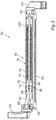
- the support arm joint device 50 as shown in a sectional schematic side view in FIG Fig. 3 is shown, provided which forms an articulated support arm.
- the support arm joint device 50 has a first fastening element 52 by means of which the support arm joint device 50 can be fastened, for example, to a ceiling of an operating room.
- the first fastening element 52 can, for example, also be arranged on a further support arm.
- the support arm joint device 50 has a second fastening element 54, which is designed, for example, to fasten a medical device, such as an operating theater lamp, or also a further support arm.
- the two fastening elements 52, 54 are connected to one another by means of a spring arm 56, the spring arm 56 allowing the two fastening elements 52, 54 to pivot relative to one another.
- the support arm joint device 50 is designed in such a way that this pivoting takes place in a vertical plane, which in the present case corresponds to the plane of the drawing Fig. 3 is equivalent to.
- the support arm joint device 50 preferably enables a height adjustment of a medical device held thereon.
- the spring arm 56 has a support arm 58 and a lever arm 60.
- the support arm 58 is formed from several parts, including a tube 72.
- the support arm 58 is mounted on the first fastening element 52 at one end by means of a bolt 64 so as to be pivotable about a support arm pivot axis. At an end facing away from this, the support arm 58 is also pivotably mounted on the second fastening element 54 by means of a further bolt 62.
- the extension from the bolt 64 to the bolt 62 corresponds to the axial extension of the support arm 58.
- the lever arm 60 is designed as a rod and is mounted on the first fastening element 52 by means of a further bolt 66 at one end so as to be pivotable about its lever arm pivot axis.
- the lever arm 60 is also mounted on a slide 70 in an axially movable manner in the tube 72 of the support arm 58 by means of a bolt 68.
- the slide is held by a threaded rod 74, around which a spiral spring 76 is arranged radially outside inside the tube 72.
- the spring arm 56 thus has a spring device 78 by means of which respective weight forces acting on the support arm joint device 50 can be supported.
- lever arm 60 and the support arm 58 with their respective support arm pivot axis or lever arm pivot axis are mounted spaced apart from one another on the first fastening element 52 results in a lever arm or angle that is different depending on the position of the support arm joint device 50, by means of which the lever arm 60 supports the support arm 58 .
- the same weight force can be equally supported. It is therefore a balanced spring arm 56.
- the respective bolts 62, 64, 66 and 68 are aligned parallel to one another.
- the respective bolts thereby form an assigned pivot axis, which in the present case is orthogonal to the plane of the paper from Fig. 3 extend.
- the respective bolts or the respective connections of parts there can therefore also be referred to as axles or bearings.
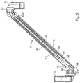
- Fig. 4 illustrates a lowermost position of the support arm joint device 50, in which the spring arm 56 or the second fastening element 54 has been pivoted downward as far as possible.
- Fig. 5 illustrates an opposite, supreme one Extreme positions of the spring arm 56. The respective directions of the forces acting and their respective associated lever arms for determining a torque acting thereby can thus be easily understood.
- Fig. 3 shows an essentially horizontal position of the support arm joint device 50.
- the support arm 58 is, for example, 70 ° with respect to a horizontal position in FIG Fig. 4 pivoted down and 45 ° in Fig. 5 up.
- the support arm joint device 50 its position or the pivot angle can be set by adjusting the threaded rod 74 and thus axially displacing the slide 70 or mounting the lever arm 60 on the support arm 58 axially along the longitudinal extent of the support arm 58.
- the threaded rod 74 is mounted in the support arm 58 or the tube 72 by means of a nut 80 at its end facing away from the slide 70.
- the mother 80 is in Fig. 7 and 9 shown in Figures 3 to 5 however not shown.
- This nut 80 is axially fixed on the support arm 58, but can be rotated about its longitudinal axis in the circumferential direction.
- the threaded rod 74 is displaced within the support arm 58.
- the slide 70 is pulled by the coupled threaded rod 74 in the corresponding direction and the spring arm 56 is adjusted upward accordingly.
- Fig. 4 shows, however, a shift in the opposite direction, whereby the spring arm 56 is lowered.
- a spring 76 of the spring device 78 is thus compressed in the downwardly pivoted position.
- any potential energy that is released when lowering a device with the support arm joint device 50 can be stored in the spring device 78.
- the spring 76 is relaxed and releases the stored energy again.
- this pivoting movement or the adjustment of the slide 70 is supported, so that the respective actuating forces when pivoting upwards can be particularly low.
- a force similar to that required for pivoting up can also be required when lowering so that the adjustment is intuitive and more precise in both directions.
- gravity acts in the Figures 3 to 5 down in the image plane.
- the spring 76 is preferably installed in a pretensioned manner.
- the spring 76 can also be in the uppermost, in Fig. 5 position shown still have a bias so that a support over the entire adjustment range of the support arm joint device 50 is made possible.
- the spring 76 is designed as a compression spring.
- the spring 76 could also be arranged in the axial direction of the support arm 58 on the side of the slide 70 facing the first fastening element 52 instead of on the side facing the second fastening element 54 in the axial direction.
- the spring 76 is supported on one side on a stop 100, by means of which a spring force can be transmitted axially to the threaded rod 74.
- the spring 76 is axially supported on a taper 98 of the tube 72.
- An insert washer is arranged on the taper 98 for better assembly.
- the taper 98 also limits a maximum axial movement of the slide 70.
- the spring 76 could also be supported directly on the slide 70.
- the adjustment device with the threaded rod 74 allows a particularly precise setting of the position of the support arm joint device 50 through the respective thread.
- the threaded rod 74 can provide a transmission ratio of an operating force, whereby the support arm joint device 50 can be moved or adjusted with little effort.
- the threaded rod 74 is self-locking, i. H. if a drive force is lost, the support arm joint device 50 does not automatically lower itself.
- the adjustment device is relieved by the spiral spring 76, which means that even lower operating forces are required. Low operating forces facilitate the adjustment and enable a more precise adjustment.
- Fig. 6 illustrates a manually adjustable embodiment of the support arm joint device 50 according to FIG Fig. 3 .
- the support arm joint device 50 according to FIG Fig. 6 a laterally arranged rotary knob 82 as an adjusting element.
- This rotary knob 82 is connected to two bevel gears 84, 86 with the nut 80 for its rotation, which in the present case is designed as a spindle nut, for example.
- This nut 80 has a groove 88 in which a stop element 90 is arranged.
- the stop element 90 is guided through a through opening in the tube 72, as shown in FIG Fig.
- the support arm joint device 50 is easy to dismantle.
- a further transmission step can also be provided, which can either reduce the required operating force or can increase an adjustment speed.
- the respective bevel gears 84, 86 allow the rotary knob 82 to be arranged transversely to the longitudinal axis of the threaded rod 74, as a result of which the support arm joint device 50 can be particularly compact.
- Fig. 8 illustrates, however, an embodiment of the support arm joint device 50 according to FIG Fig. 3 , in which an adjustment takes place by means of a motor 92.
- this motor 92 is designed as an electric gear motor which is arranged in an axial extension of the support arm 58.
- the motor 92 is, as in the sectional view according to FIG Fig. 9 is to be recognized, fastened to the tube 72 by means of respective clamping screws 94 and clamped with the nut 80 and thus connected to the threaded rod 74 for force transmission.
- the nut 80 is also axially fixed in this embodiment, but rotatable in the circumferential direction.
- the nut 80 can be analogous to the embodiment according to FIG Fig.
- the motor 92 could also be connected directly to the threaded rod 74 for adjusting or rotating it.
- the motor 92 can also be arranged at least partially in the tube 72, since this only has to provide a low torque and a low power due to the construction of the support arm joint device 50. As a result, the support arm joint device 50 can be particularly compact and simple.
- the support arm joint device 50 can have a parallel guide element 94.
- the parallel guide element 94 is in the present case designed as a rod which is mounted pivotably on the first fastening element 52 with a first end and pivotably with a second end on the second fastening element 54.
- a nodding movement of the two fastening elements 52, 54 is synchronized with a pivoting movement of the spring arm 56.
- an alignment of the two fastening elements 52, 54 can remain the same in all positions of the spring arm 56. This is immediate by comparing the Fig. 3 , Fig. 4 and Fig. 5 can be seen with each other, in which the alignment of the two fastening elements 52, 54 remains the same in the image or drawing plane.
Landscapes
- Health & Medical Sciences (AREA)
- Engineering & Computer Science (AREA)
- Surgery (AREA)
- Life Sciences & Earth Sciences (AREA)
- Animal Behavior & Ethology (AREA)
- General Health & Medical Sciences (AREA)
- Biomedical Technology (AREA)
- Heart & Thoracic Surgery (AREA)
- Medical Informatics (AREA)
- Molecular Biology (AREA)
- Nuclear Medicine, Radiotherapy & Molecular Imaging (AREA)
- Veterinary Medicine (AREA)
- Public Health (AREA)
- General Engineering & Computer Science (AREA)
- Oral & Maxillofacial Surgery (AREA)
- Pathology (AREA)
- Robotics (AREA)
- Mechanical Engineering (AREA)
- Manipulator (AREA)
- Surgical Instruments (AREA)
Abstract
Die Erfindung betrifft eine Tragarmgelenkvorrichtung (50) zum bewegbaren Halten eines medizinischen Geräts,aufweisend ein erstes und zweites Befestigungselement (52, 54), welche mittels eines Federarms (56) verschwenkbar miteinander verbunden sind,wobei der Federarm (56) einen Stützarm (58) und einen Hebelarm (60) aufweist, welche mit einer zugeordneten Stützarmschwenkachse (64) und Hebelarmschwenkachse (66) an dem ersten Befestigungselement (52) verschwenkbar gelagert sind,wobei die beiden Schwenkachsen (64, 66) voneinander beabstandet sind,wobei der Stützarm (58) an dem zweiten Befestigungselement (54) verschwenkbar gelagert ist und der Hebelarm (60) mittels einer Federvorrichtung (78) an dem Stützarm (58) gelagert ist, sodass eine Gewichtskraft des gehaltenen medizinischen Geräts bei unterschiedlichen Schwenkpositionen abgestützt wird,wobei die Federvorrichtung (78) eine Verstellvorrichtung aufweist, mittels welcher eine Position der Lagerung (68, 70) des Hebelarms (60) an dem Stützarm (58) entlang einer Längserstreckung des Stützarms (58) einstellbar ist.Weiterhin betrifft die Erfindung ein Tragarmsystem und ein Verfahren zum Betreiben einer Tragarmgelenkvorrichtung.The invention relates to a support arm joint device (50) for movably holding a medical device, having a first and second fastening element (52, 54) which are pivotably connected to one another by means of a spring arm (56), the spring arm (56) having a support arm (58). and a lever arm (60) which are pivotably mounted on the first fastening element (52) with an associated support arm pivot axis (64) and lever arm pivot axis (66), the two pivot axes (64, 66) being spaced from one another, the support arm (58 ) is pivotably mounted on the second fastening element (54) and the lever arm (60) is mounted on the support arm (58) by means of a spring device (78) so that a weight of the medical device held is supported in different pivoting positions, the spring device (78 ) has an adjusting device, by means of which a position of the bearing (68, 70) of the lever arm (60) on the support arm (58) is adjustable along a longitudinal extension of the support arm (58). Furthermore, the invention relates to a support arm system and a method for operating a support arm joint device.
Description
Die vorliegende Erfindung betrifft eine Tragarmgelenkvorrichtung für ein Tragsystem zum Halten wenigstens eines medizinischen Geräts sowie ein Tragsystem für ein medizinisches Gerät.The present invention relates to a support arm joint device for a support system for holding at least one medical device and a support system for a medical device.
Tragarmsysteme werden beispielsweise in Operationssälen zum örtlichen verlagerbaren Halten eines medizintechnischen Einrichtung bzw. Geräts genutzt. Beispielsweise kann dazu ein Tragarm beweglich mittels einer Lageranordnung an einer Decke, einer Wand oder einem Boden verankert sein. Auch eine Befestigung auf einem Gestell mit Rollen ist möglich. Ein Tragsystem mit wenigstens einem Tragarm kann auch als Tragarmsystem bezeichnet werden und ein Tragsystem, welches zum Halten medizinischer Geräte ausgebildet ist, kann auch als medizinisches Tragsystem bezeichnet werden. Tragsysteme weisen üblicherweise wenigstens eine Bewegungsachse auf, damit das gehaltene medizinischen Gerät, welches auch als medizintechnisches Gerät bezeichnet werden und beispielsweise eine OP-Lampe, einen Monitor, Untersuchungsgeräte, einen oder mehrere Injektoren, OP-Besteck oder zahnmedizinische Bohrer aufweisen kann, gemäß jeweiliger Anforderungen bewegt werden kann. Die Lagerung, welche die Bewegung ermöglicht, kann auch als Gelenkvorrichtung oder Tragarmgelenkvorrichtung bezeichnet werden, wobei diese auch einen Tragarm umfassen kann. Damit kann das medizinische Gerät in eine angenehme und sichere Position zum Durchführen jeweiliger medizinischer Prozeduren und Überwachungen verbracht werden. Das örtliche Verlagern medizinischer Geräte ist bei vielen medizinischen Prozeduren essentiell, um dem medizinischen Personal die Arbeit zu erleichtern oder überhaupt zu ermöglichen.Support arm systems are used, for example, in operating theaters for locally displaceable holding of a medical device or device. For example, a support arm can be movably anchored to a ceiling, a wall or a floor by means of a bearing arrangement for this purpose. It can also be attached to a frame with rollers. A support system with at least one support arm can also be referred to as a support arm system and a support system which is designed to hold medical devices can also be referred to as a medical support system. Support systems usually have at least one axis of movement so that the medical device held, which is also referred to as a medical device and can have, for example, an operating lamp, a monitor, examination devices, one or more injectors, surgical instruments or dental drills, in accordance with the respective requirements can be moved. The mounting that enables the movement can also be referred to as a joint device or a support arm joint device, it also being possible for this to include a support arm. In this way, the medical device can be brought into a comfortable and safe position for carrying out the respective medical procedures and monitoring. The local relocation of medical devices is essential in many medical procedures in order to facilitate the work of the medical staff or to enable them at all.
Durch ein Schwenken eines Tragarms kann jedoch ein Hebelarm bezüglich dessen Lagerung verändert werden. Insbesondere bei einem Schwenken des Tragarms um eine im Wesentlichen horizontale Achse, wodurch die Höhe des daran gehaltenen medizinischen Geräts verändert werden kann, wird ein Hebelarm der Gewichtskraft des medizinischen Geräts gegenüber der Befestigung bzw. Lagerung des Tragarms verändert. Dennoch ist es gewünscht, dass das medizinische Gerät dabei in einer durch das Schwenken des Tragarms eingestellten Position bleibt.By pivoting a support arm, however, a lever arm can be changed with regard to its mounting. In particular when the support arm is pivoted about an essentially horizontal axis, as a result of which the height of the medical device held thereon can be changed, the weight of the medical device becomes a lever arm changed compared to the attachment or storage of the support arm. Nevertheless, it is desirable for the medical device to remain in a position set by pivoting the support arm.
Zu diesem Zweck werden häufig federbalancierte Tragarme oder Tragarmgelenkvorrichtungen genutzt. Dabei werden zwei voneinander beabstandete Arme vorgesehen, welche sich mittels einer Feder gegenseitig stützen. Durch Verschwenken des federbalancierten Tragarms ändert sich dabei der Hebelarm der Federkraft korrespondierend zu dem Hebelarm der Traglast, wodurch das medizinische Gerät in unterschiedlichen Positionen gleichermaßen gut gehalten werden kann. Alternativ oder zusätzlich kann auch die Feder durch das Schwenken komprimiert oder gestreckt werden, wodurch ebenfalls eine korrespondierende Stützkraft geändert werden kann.Spring-balanced support arms or support arm joint devices are often used for this purpose. Two arms spaced apart from one another are provided, which mutually support one another by means of a spring. By pivoting the spring-balanced support arm, the lever arm of the spring force changes to correspond to the lever arm of the load, so that the medical device can be held equally well in different positions. Alternatively or additionally, the spring can also be compressed or stretched by pivoting, whereby a corresponding supporting force can also be changed.
Eine solche Tragarmgelenkvorrichtung ist beispielsweise in der
Bekannt ist es auch, Bremsen zu verwenden, welche einen Tragarm in Position halten. Bremsen haben jedoch den Nachteil, dass sie verschleißen. Zudem ist auch eine Lastanpassung bei Bremsen gegebenenfalls notwendig.It is also known to use brakes which hold a support arm in position. However, brakes have the disadvantage that they wear out. In addition, it may be necessary to adjust the load when braking.
Weiterhin bekannt ist ein direktes Verschwenken mittels eines Motors, welcher an einer Lagerung eines Tragarms angeordnet ist. Dafür kann jedoch ein großer und starker Motor notwendig sein. Ein Beispiel für solch eine Technologie wird später noch anhand von Figuren detaillierter erläutert.Also known is a direct pivoting by means of a motor which is arranged on a bearing of a support arm. However, this may require a large and powerful engine. An example of such a technology will be explained in more detail later on the basis of figures.
Aufgabe der vorliegenden Erfindung ist es, eine verbesserte Tragarmgelenkvorrichtung, ein verbessertes Tragarmsystem und ein verbessertes Verfahren zum Betreiben einer Tragarmgelenkvorrichtung bereitzustellen. Insbesondere soll ein kostengünstiges Halten von medizinischen Geräten in einer präzise einstellbaren Stellung einfach ermöglicht werden.The object of the present invention is to provide an improved support arm joint device, an improved support arm system and an improved method for operating a support arm joint device. In particular, inexpensive holding of medical devices in a precisely adjustable position should be made possible in a simple manner.
Diese Aufgaben werden erfindungsgemäß durch die Gegenstände der unabhängigen Patentansprüche gelöst. Vorteilhafte Ausgestaltungen mit zweckmäßigen Weiterbildungen der Erfindung sind in den jeweiligen Unteransprüchen angegeben, wobei vorteilhafte Ausgestaltungen eines Aspekts als vorteilhafte Ausgestaltungen jeweiliger anderer Aspekte und umgekehrt anzusehen sind.According to the invention, these objects are achieved by the subjects of the independent claims. Advantageous refinements with expedient refinements of the invention are specified in the respective subclaims, with advantageous refinements of one aspect being regarded as advantageous refinements of respective other aspects and vice versa.
Ein erster Aspekt der Erfindung betrifft eine Tragarmgelenkvorrichtung für ein Tragsystem zum bewegbaren Halten wenigstens eines medizinischen Geräts. Nach einem Bewegen des Geräts kann dabei dessen Position bzw. Stellung gehalten werden, was auch als Fixierung in der Stellung bzw. Position bezeichnet werden kann.A first aspect of the invention relates to a support arm joint device for a support system for movably holding at least one medical device. After the device has been moved, its position or posture can be held, which can also be referred to as fixing in the posture or position.
Die Tragarmgelenkvorrichtung weist ein erstes und ein zweites Befestigungselement auf, welche mittels eines Federarms relativ verschwenkbar zueinander miteinander verbunden sind. Der Federarm ist dabei auch Teil der Tragarmgelenkvorrichtung und ermöglicht durch ein Verschwenken wenigstens um eine Schwenkachse, bevorzugt in einer Schwenkebene, die beiden Befestigungselemente relativ zueinander zu bewegen. Eines der beiden Befestigungselemente, bevorzugt das erste Befestigungselement, kann ortsfest sein, beispielsweise durch eine Verankerung an einer Wand. Das andere Befestigungselement kann so vorzugsweise relativ zu dieser Verankerung verschwenkt werden, insbesondere um dessen Höhe zu ändern.The support arm joint device has a first and a second fastening element which are connected to one another in a relatively pivotable manner by means of a spring arm. The spring arm is also part of the support arm joint device and enables the two fastening elements to be moved relative to one another by pivoting at least about a pivot axis, preferably in a pivot plane. One of the two fastening elements, preferably the first fastening element, can be stationary, for example by being anchored to a wall. The other fastening element can thus preferably be pivoted relative to this anchorage, in particular in order to change its height.
Der Federarm kann einen Stützarm und einen Hebelarm aufweisen, welche mit einer zugeordneten Stützarmschwenkachse und Hebelarmschwenkachse an dem ersten Befestigungselement verschwenkbar gelagert sind. Diese beiden Schwenkachsen sollten voneinander beabstandet sein, wobei die Schwenkachsen bevorzugt parallel zueinander angeordnet sind. Der Stützarm und der Hebelarm werden vorzugsweise bei einer Schwenkbewegung des Federarms bzw. beim Verschwenken der beiden Befestigungselemente relativ zueinander ebenfalls verschwenkt. Wenigstens eines der beiden Befestigungselemente ist gelenkig an dem Federarm angeordnet, insbesondere das erste Befestigungselement gelenkig sowohl an dem Stützarm als auch an dem Hebelarm. Bevorzugt ist das andere Befestigungselement, insbesondere das zweite Befestigungselement, ebenfalls gelenkig an dem Federarm gelagert, vorzugsweise ausschließlich an dem Stützarm.The spring arm can have a support arm and a lever arm which are pivotably mounted on the first fastening element with an associated support arm pivot axis and lever arm pivot axis. These two pivot axes should be spaced apart from one another, the pivot axes preferably being arranged parallel to one another. The support arm and the lever arm are preferably also pivoted relative to one another during a pivoting movement of the spring arm or upon pivoting of the two fastening elements. At least one of the two fastening elements is articulated on the spring arm, in particular the first fastening element is articulated both on the support arm and on the lever arm. The other fastening element, in particular the second fastening element, is preferably likewise mounted in an articulated manner on the spring arm, preferably exclusively on the support arm.
Der Stützarm ist bevorzugt an dem zweiten Befestigungselement verschwenkbar gelagert. Der Hebelarm ist dagegen beispielsweise mittels einer Federvorrichtung an dem Stützarm derart gelagert ist, dass eine Gewichtskraft des gehaltenen medizinischen Geräts bei unterschiedlichen Schwenkpositionen abgestützt wird. Durch die Federvorrichtung und die beabstandete Lagerung von Stützarm und Hebelarm kann sich eine Stützkraft der Tragarmgelenkvorrichtung automatisch an deren Schwenkwinkel bzw. deren Schwenkposition anpassen, um die Gewichtskraft gleichermaßen bei unterschiedlichen Hebelarmlängen der Gewichtskraft abzustützen. Die Tragarmgelenkvorrichtung ist so selbstbalancierend und/oder unterstützt ein Verstellen des Schwenkwinkels gegen die Schwerkraft.The support arm is preferably mounted pivotably on the second fastening element. The lever arm, on the other hand, is mounted on the support arm, for example by means of a spring device, in such a way that a weight force of the medical device being held is supported in different pivoting positions. Due to the spring device and the spaced-apart mounting of the support arm and lever arm, a support force of the support arm joint device can automatically adapt to its pivot angle or its pivot position in order to equally support the weight force with different lever arm lengths of the weight force. The support arm joint device is thus self-balancing and / or supports an adjustment of the pivot angle against gravity.
Zusätzlich zu der Gewichtskraft des medizinischen Geräts kann so auch das Eigengewicht jeweiliger Komponenten der Tragarmgelenkvorrichtung abgestützt bzw. ausbalanciert werden. Beispielsweise wirkt auch eine Gewichtskraft eines nicht verankerten der beiden Befestigungselemente mit unterschiedlichen Hebelarmen, womit unterschiedliche Drehmomente je nach Stellung der Tragarmgelenkvorrichtung abgestützt werden sollte.In addition to the weight of the medical device, the weight of the respective components of the support arm joint device can also be supported or balanced. For example, a weight force of a non-anchored one of the two fastening elements also acts with different lever arms, whereby different torques should be supported depending on the position of the support arm joint device.
Im Rahmen dieser Anmeldung betrifft der Hebelarm ein Bauteil der Tragarmgelenkvorrichtung, welcher beispielsweise als Stab, Stange Rohr, Hohlprofil oder dergleichen ausgebildet sein kann. Dieser Hebelarm stützt das zu haltende medizinische Gerät mit ab. Hebelarme im Kontext von Kräften bezeichnen dagegen den Abstand eines Kraftangriffspunkts von einem Drehgelenk bzw. Drehpunkt. Solche Hebelarme bezeichnen also eine Länge, durch deren Multiplikation mit der jeweiligen Kraft sich das an dem Drehpunkt wirkende Drehmoment, häufig auch als Moment bezeichnet, berechnen lässt.In the context of this application, the lever arm relates to a component of the support arm joint device, which can be designed, for example, as a rod, rod, tube, hollow profile or the like. This lever arm also supports the medical device to be held. Lever arms in the context of forces, on the other hand, denote the distance between a force application point and a swivel joint or pivot point. Such lever arms thus designate a length, the multiplication of which by the respective force enables the torque acting at the pivot point, often also referred to as the moment, to be calculated.
Die Federvorrichtung kann eine Verstellvorrichtung aufweisen, mittels welcher eine Position der Lagerung des Hebelarms an dem Stützarm entlang einer Längserstreckung des Stützarms einstellbar ist. Durch diese Positionsverstellung wird also eine Position verstellt, an welcher der Hebelarm an dem Stützarm angreift. Alternativ oder zusätzlich kann so auch ein Schwenkwinkel des Hebelarms bezüglich der Hebelarmschwenkachse eingestellt werden. Insgesamt ergibt sich durch diese Verstellung ein Schwenkwinkel der Tragarmgelenkvorrichtung bzw. eine relative Position der beiden Befestigungselemente zueinander. Durch Verschieben der Lagerung des Hebelarms am Stützarm und/oder ein Verschieben eines Kraftangriffspunkts kann also ein Schwenkwinkel der Tragarmgelenkvorrichtung bzw. des Federarms eingestellt werden.The spring device can have an adjusting device, by means of which a position of the mounting of the lever arm on the support arm can be adjusted along a longitudinal extension of the support arm. This position adjustment therefore adjusts a position at which the lever arm engages the support arm. As an alternative or in addition, a pivot angle of the lever arm with respect to the lever arm pivot axis can also be set in this way. Overall, this adjustment results in a pivot angle of the support arm joint device or a relative position of the two fastening elements to one another. By moving the mounting of the lever arm on the support arm and / or moving a A pivot angle of the support arm joint device or of the spring arm can therefore be set at the force application point.
Vorzugsweise ist die Verstellvorrichtung dazu ausgebildet, dass sich ein Spannungszustand des Federarms bzw. der Federvorrichtung durch ein Verstellen der Lagerung des Hebelarms an dem Stützarm ändert. Beispielsweise kann entsprechend eine Feder komprimiert oder entspannt werden. Bevorzugt ist die Federvorrichtung dabei dazu ausgebildet, eine frei werdende potentielle Energie bei einem Absenken der Tragarmgelenkvorrichtung bzw. des daran gehaltenen medizinischen Geräts zu speichern und beim Anheben der Tragarmgelenkvorrichtung bzw. des daran gehaltenen medizinischen Geräts wieder abzugeben. Beispielsweise kann beim Absenken des Federarms durch Verstellen der Lagerung des Hebelarms an dem Stützarm eine Feder der Federvorrichtung komprimiert werden und beim Anheben des Federarms durch Verstellen der Lagerung des Hebelarms an dem Stützarm eine Feder der Federvorrichtung entspannt werden. Entsprechend stützt die Feder beim Absenken, wodurch geringere Stützkräfte aufgebracht werden müssen. Beim Anheben gibt die Feder die beim Absenken gespeicherte Energie wieder ab, wodurch ein Kraftaufwand zum Anheben geringer ist. Dadurch ist eine präzise Positionseinstellung mit geringem Kraftaufwand und einer simplen Mechanik einfach möglich. Gegebenenfalls muss sogar bei der Abwärtsbewegung eine Kraft zusätzlich zum Eigengewicht aufgebracht werden, um den Federarm entgegen der stützenden Federkraft zu bewegen. Die Tragarmgelenkvorrichtung, insbesondere die Federvorrichtung, kann so ausgebildet sein, dass beim Absenken und Anheben annähernd die gleichen Kräfte benötigt werden. Damit ist die Bedienung und Positionseinstellung besonders intuitiv und präzise möglich.The adjustment device is preferably designed so that a tension state of the spring arm or the spring device changes by adjusting the mounting of the lever arm on the support arm. For example, a spring can be compressed or relaxed accordingly. The spring device is preferably designed to store a potential energy released when the support arm joint device or the medical device held thereon is lowered and to release it again when the support arm joint device or the medical device held thereon is raised. For example, when lowering the spring arm by adjusting the mounting of the lever arm on the support arm, a spring of the spring device can be compressed and when lifting the spring arm by adjusting the mounting of the lever arm on the support arm, a spring of the spring device can be relaxed. Correspondingly, the spring provides support when lowering, which means that lower supporting forces have to be applied. When lifting, the spring releases the energy stored during lowering, which means that less effort is required to lift it. This enables precise position adjustment with little effort and a simple mechanism. It may even be necessary to apply a force in addition to its own weight during the downward movement in order to move the spring arm against the supporting spring force. The support arm joint device, in particular the spring device, can be designed in such a way that approximately the same forces are required when lowering and lifting. This enables operation and position adjustment to be particularly intuitive and precise.
Die Tragarmgelenkvorrichtung erlaubt also einen balancierten Tragarm mit einem einstellbaren Schwenkwinkel bereitzustellen. Durch das Einstellen an der Federvorrichtung kann dabei auch ein Ziehen an irgendeiner Komponente zum Verstellen verzichtet werden und stattdessen eine mechanische Einstellbarkeit bereitgestellt werden. Diese erlaubt ein wesentlich präziseres und/oder schnelleres Einstellen, insbesondere durch eine Untersetzung oder Übersetzung beispielsweise an einem Einstellelement, wie einem Drehknopf.The support arm joint device thus allows a balanced support arm with an adjustable pivot angle to be provided. By adjusting the spring device, it is also possible to dispense with pulling any component for adjustment and instead provide mechanical adjustability. This allows a much more precise and / or faster setting, in particular by means of a reduction or translation, for example on an adjusting element such as a rotary knob.
Auch kann die Verstellvorrichtung selbsthemmend, selbstblockierend und/oder arretierend ausgebildet sein. Beispielsweise kann eine Verstellschraube, wie eine Gewindestange, vorgesehen werden, welche durch eine Gewindesteigung ein Verstellen der Position der Lagerung des Hebelarms durch Gewichtskräfte des medizinischen Geräts verhindert. Dadurch wird dessen Position präzise gehalten. Auch ein Nachschwingen nach einer Verstellung kann so wirksam verhindert oder zumindest reduziert werden.The adjusting device can also be designed to be self-locking, self-locking and / or locking. For example, an adjusting screw, such as a threaded rod, can be provided which, by means of a thread pitch, prevents the position of the mounting of the lever arm from being adjusted by the weight of the medical device. This keeps its position precisely. Post-oscillation after an adjustment can also be effectively prevented or at least reduced in this way.
Insbesondere kann so auch ein motorisch und/oder mechanisch verstellbarer Federarm im Bereich von leichten und mittelgroßen Lasten zur Verfügung gestellt werden. Der Aufbau ist einfach und kostengünstig. Die Verstellvorrichtung kann für eine stufenlose Verstellung ausgebildet sein, insbesondere eine stufenlose Positionierung und/oder Höhenverstellung. Auch bei Traglastverlusten, beispielsweise durch ein Abmontieren des medizinischen Geräts, und/oder zusätzliche Lasten, beispielsweise ein Drücken auf Bedienfelder des medizinischen Geräts, kann der Federarm in Position bleiben, insbesondere durch die beschriebene Selbsthemmung.In particular, a motorized and / or mechanically adjustable spring arm in the area of light and medium-sized loads can also be made available. The construction is simple and inexpensive. The adjustment device can be designed for stepless adjustment, in particular stepless positioning and / or height adjustment. The spring arm can also remain in position in the event of a load loss, for example due to dismantling of the medical device, and / or additional loads, for example pressing on control panels of the medical device, in particular due to the self-locking described.
Die Federvorrichtung kann beispielsweise eine vorgespannte Feder aufweisen, welche beispielsweise bereits einen großen Teil der wirkenden Lasten trägt bzw. ausbalanciert. Ein Verstellen benötigt so nur noch sehr geringe Kräfte, womit beispielsweise eine geringe Bedienkraft und/oder nur ein kleiner Motor notwendig ist/sind. Vorzugsweise ist die Feder als Schraubenfeder und/oder Druckfeder ausgebildet. Auch die Gefahr durch mögliche Kollisionen bei einer Fehlbedienung ist so geringer, da die dann wirkenden Bedienkräfte ebenfalls gering ist. Bei einem Einsatz als Teil eines Robotikarms können so beispielsweise deutlich weniger Risikovermeidungsmaßnahmen notwendig sein.The spring device can, for example, have a pretensioned spring which, for example, already bears or balances a large part of the loads acting. Adjustment thus only requires very small forces, which means that, for example, a small operating force and / or only a small motor is / are necessary. The spring is preferably designed as a helical spring and / or a compression spring. The risk of possible collisions in the event of incorrect operation is also lower because the operating forces then acting are also low. When used as part of a robotic arm, for example, significantly fewer risk avoidance measures may be necessary.
Die jeweiligen Befestigungselemente können beispielsweise zum Halten des medizinischen Geräts, eines Tragarms und/oder einer weiteren Tragarmgelenkvorrichtung ausgebildet sein. Bevorzugt ist das medizinische Gerät an dem zweiten Befestigungselement befestigt. Das medizinische Gerät kann beispielsweise ein Monitor, ein EKG-Gerät, ein Gerät für Infusionen und/oder Operationen sein, Teil einer Bohrvorrichtung für Zahnärzte oder auch eines Tabletts zum Halten medizinischer Werkzeuge, wie Skalpelle und dergleichen, sein. Eines der Befestigungselemente kann beispielsweise zur Befestigung an einer Wand, einer Decke, einem Boden und/oder einer beweglichen oder stationären Basiseinheit ausgebildet sein. Die Befestigungselemente können beispielsweise eine Kopplung, wie jeweilige Schrauben und/oder Schnellspanner, zum Befestigen von jeweiligen Teilen des Tragarmsystems daran, wie beispielsweise weiteren Tragarmen und/oder des medizinischen Geräts, aufweisen. Eines oder beide der Befestigungselemente kann/können auch zum Koppeln mit einem Tragarm ausgebildet sein, insbesondere zu einem bewegbaren Koppeln. Beispielsweise kann das jeweilige Befestigungselement hierzu ein Lager und/oder ein Gelenk aufweisen. Dadurch kann das Befestigungselemente und damit auch das medizinische Gerät relativ zu dem Federarm und/oder dem anderen Befestigungselement ausgerichtet werden, beispielsweise durch Drehung in einer vertikalen oder horizontalen Ebene. Insgesamt ergibt sich eine flexible und/oder modulare Gestaltung.The respective fastening elements can be designed, for example, to hold the medical device, a support arm and / or a further support arm joint device. The medical device is preferably fastened to the second fastening element. The medical device can, for example, be a monitor, an EKG device, a device for infusions and / or operations, part of a drilling device for dentists or also a tray for holding medical tools such as scalpels and the like. One of the fastening elements can be designed, for example, for fastening to a wall, a ceiling, a floor and / or a movable or stationary base unit. The fastening elements can, for example, be a coupling, such as respective screws and / or quick-release clamps, for fastening respective parts of the support arm system to it, such as further support arms and / or the medical device. One or both of the fastening elements can also be designed for coupling to a support arm, in particular for movable coupling. For example, the respective fastening element can have a bearing and / or a joint for this purpose. As a result, the fastening element and thus also the medical device can be aligned relative to the spring arm and / or the other fastening element, for example by rotating in a vertical or horizontal plane. Overall, the result is a flexible and / or modular design.
Der Hebelarm und der Stützarm können als längliche Bolzen, Stange, Stab, Zylinder, Hohlprofile, Massivprofile und/oder ähnliches ausgebildet sein. Als Materialien kommen beispielsweise Kunststoff oder Metall zum Einsatz. Der Hebelarm und der Stützarm können einteilig oder mehrteilig ausgebildet sein. Vorzugsweise sind der Hebelarm und der Stützarm mit einem jeweiligen Ende an deren zugeordneten Stützarmschwenkachse bzw. Hebelarmschwenkachse gelagert, also mit dem jeweiligen Ende an dem ersten Befestigungselement. Mit seinem gegenüberliegenden Ende ist der Stützarm bevorzugt an dem zweiten Befestigungselement gelagert, insbesondere schwenkbar oder drehfest. Der Hebelarm ist mit seinem gegenüberliegenden Ende bevorzugt an der der Federvorrichtung, insbesondere der Verstellvorrichtung, und/oder an dem Stützarm gelagert. Diese Lagerung sollte axial verstellbar sein, um die Schwenkverstellung. Vorzugsweise ist die Lagerung dabei axial entlang der Längserstreckung des Stützarms durch die Federvorrichtung abgestützt, um jeweilige zum Verstellen notwendige Kräfte mittels der Federvorrichtung stützen zu können.The lever arm and the support arm can be designed as elongated bolts, rods, rods, cylinders, hollow profiles, solid profiles and / or the like. Plastic or metal, for example, are used as materials. The lever arm and the support arm can be formed in one piece or in several pieces. The lever arm and the support arm are preferably mounted with a respective end on their associated support arm pivot axis or lever arm pivot axis, that is to say with the respective end on the first fastening element. With its opposite end, the support arm is preferably mounted on the second fastening element, in particular pivotably or non-rotatably. The opposite end of the lever arm is preferably mounted on that of the spring device, in particular the adjusting device, and / or on the support arm. This storage should be axially adjustable to allow the swivel adjustment. The mounting is preferably supported axially along the longitudinal extension of the support arm by the spring device in order to be able to support the respective forces required for adjustment by means of the spring device.
Der Hebelarm ist mittels der Federvorrichtung vorzugsweise von dem zweiten Befestigungselement beabstandet an dem Stützarm gehalten. Der Hebelarm kann dabei mittelbar über die Federvorrichtung bzw. Verstellvorichtung an dem Stützarm gehalten sein oder auch direkt an diesem gelagert sein, wobei die Verstellvorrichtung eine Bewegung der Lagerung bewirkt und/oder die Federvorrichtung einen Kraftfluss von dem Hebelarm zu dem Stützarm ermöglicht, insbesondere entlang der axialen Erstreckung des Stützarms.The lever arm is preferably held at a distance from the second fastening element on the support arm by means of the spring device. The lever arm can be held on the support arm indirectly via the spring device or adjusting device or can also be mounted directly on it, the adjusting device causing a movement of the mounting and / or the spring device enabling a flow of force from the lever arm to the support arm, in particular along the axial extension of the support arm.
Das eine der beiden Befestigungselemente kann mittels des Federarms relativ zu dem anderen der beiden Befestigungselemente örtlich verlagert werden, insbesondere in einer Hoch- bzw. Vertikalrichtung. Alternativ oder zusätzlich kann mittels Tragarmgelenkvorrichtung, insbesondere mittels des Federarms, auch eine örtliche Verlagerung in einer Quer- bzw. Horizontalrichtung ermöglicht werden. Vorzugsweise ist dabei nur eine Schwenkebene, insbesondere eine vertikale ausgerichtete Schwenkebene für das Verstellen in Hochrichtung, mittels des Federarms ausbalanciert. Beispielsweise sind die jeweiligen Befestigungselemente an gegenüberliegenden Enden des Federarms an diesem angeordnet, insbesondere befestigt.One of the two fastening elements can be locally displaced by means of the spring arm relative to the other of the two fastening elements, in particular in an upright or vertical direction. Alternatively or additionally, using a support arm joint device, in particular by means of the spring arm, a local displacement in a transverse or horizontal direction can also be made possible. Preferably, only one swivel plane, in particular a vertically aligned swivel plane for adjustment in the vertical direction, is balanced by means of the spring arm. For example, the respective fastening elements are arranged, in particular fastened, on opposite ends of the spring arm.
In weiterer vorteilhafter Ausgestaltung der Tragarmgelenkvorrichtung ist es vorgesehen, dass die Federvorrichtung eine Feder aufweist. Eine Feder ist ein einfaches Element zum Aufnehmen bzw. Speichern und Abgeben potentieller Energie, womit ein Ausbalancieren mit einfachen Mitteln möglich ist und/oder eine Verstell- bzw. Bedienkraft besonders klein sein kann. Beispielsweise ist eine hydraulische oder mechanische Feder geeignet, insbesondere eine Gasdruckfeder und/oder eine Schraubenfeder. Eine mechanische Feder ist besonders kostengünstig und robust. Zusätzlich kann die Federvorrichtung auch eine Dämpfung aufweisen, welche beispielsweise ein plötzliches Hochschnellen bei Entlastung, z.B. durch Abnahme des medizinischen Geräts, verhindert. Diese Dämpfung kann besonders einfach in einer hydraulischen Feder integriert sein. Vorzugsweise ist die Feder im Wesentlichen innerhalb des Stützarms geführt und/oder angeordnet. Dadurch ist die Feder vor Umwelteinflüssen geschützt angeordnet und/oder ein Verletzungsrisiko durch Fehlbedienung, beispielsweise ein Greifen der Feder, kann minimiert werden. Im Wesentlichen bedeutet hier insbesondere, dass die Feder je nach Position der Tragarmgelenkvorrichtung bzw. des Federarms und/oder der Lagerung des Hebelarms, teilweise aus dem Stützarm ragen kann. Bevorzugt ist die Feder in jeder Position vollständig im Stützarm aufgenommen. Der Stützarm kann hierzu ein Federrohr umfassen oder als solches ausgebildet sein.In a further advantageous embodiment of the support arm joint device, it is provided that the spring device has a spring. A spring is a simple element for absorbing or storing and releasing potential energy, with which balancing is possible with simple means and / or an adjustment or operating force can be particularly small. For example, a hydraulic or mechanical spring is suitable, in particular a gas pressure spring and / or a helical spring. A mechanical spring is particularly inexpensive and robust. In addition, the spring device can also have a damping system, which prevents, for example, a sudden jump up when the load is removed, for example when the medical device is removed. This damping can be integrated particularly easily in a hydraulic spring. The spring is preferably guided and / or arranged essentially within the support arm. As a result, the spring is arranged so that it is protected from environmental influences and / or the risk of injury due to incorrect operation, for example grasping the spring, can be minimized. Essentially here means in particular that the spring can partially protrude from the support arm, depending on the position of the support arm joint device or the spring arm and / or the mounting of the lever arm. The spring is preferably completely received in the support arm in every position. For this purpose, the support arm can comprise a spring tube or be designed as such.
In weiterer vorteilhafter Ausgestaltung der Tragarmgelenkvorrichtung ist es vorgesehen, dass der Hebelarm verschwenkbar an der Federvorrichtung gelagert ist, insbesondere mit einer Schwenkachse parallel zu der Hebelarmschwenkachse, mittels welcher der Hebelarm an dem ersten Befestigungselement gelagert ist. Die Position dieser Schwenkachse kann axial entlang des Stützarms verschiebbar sein. Eine entsprechende Lagerung kann auch als Hebellager bezeichnet werden. Bevorzugt ist der Hebelarm innerhalb des Stützarms und/oder einer Verkleidung gelagert, um ein Quetschungsrisiko zu reduzieren und Beschädigungen zuverlässig zu vermeiden.In a further advantageous embodiment of the support arm joint device, it is provided that the lever arm is pivotably mounted on the spring device, in particular with a pivot axis parallel to the lever arm pivot axis, by means of which the lever arm is mounted on the first fastening element. The position of this pivot axis can be axially displaceable along the support arm. A corresponding storage can also be referred to as a lever bearing. The lever arm is preferably mounted within the support arm and / or a cladding in order to reduce the risk of crushing and to reliably avoid damage.
In weiterer vorteilhafter Ausgestaltung der Tragarmgelenkvorrichtung ist es vorgesehen, dass der Hebelarm mittels eines Schlittens an dem Stützarm entlang dessen Längserstreckung gelagert ist, wobei der Schlitten vorzugsweise im Wesentlichen innerhalb des Stützarms geführt ist. Insbesondere kann der Schlitten axial beweglich an oder in dem Stützarm an diesem gelagert sein. In der einfachsten Form ist der Schlitten an einen Innendurchmesser eines Rohrs des Stützarms angepasst und so geführt. Insbesondere kann der Hebelarm verschwenkbar an dem Schlitten gelagert sein. Der Schlitten erlaubt eine einfache Führung des Hebelarms bei einer axialen Verstellbarkeit und Kraftübertragung an die bzw. von der Federvorrichtung. Die Anordnung innerhalb erlaubt auch hier den Schutz der Teile und von Personen. Insbesondere eine Verschmutzung und damit frühzeitiger Verschleiß kann so vermieden werden. Der Schlitten kann Teil der Verstellvorrichtung sein und wird axial am Stützarm beim Einstellen der Position der Lagerung verschoben. Der Schlitten kann, je nach Position, teilweise aus dem Stützarm ragen oder in jeder Position vollständig darin aufgenommen sein.In a further advantageous embodiment of the support arm joint device, it is provided that the lever arm is mounted on the support arm along its longitudinal extension by means of a slide, the slide preferably being guided essentially within the support arm. In particular, the slide can be axially movably mounted on or in the support arm on the latter. In its simplest form, the slide is adapted to an inner diameter of a tube of the support arm and is guided in this way. In particular, the lever arm can be mounted pivotably on the slide. The slide allows simple guidance of the lever arm with axial adjustability and power transmission to and from the spring device. The arrangement within allows the parts and people to be protected. In particular, contamination and thus premature wear can be avoided in this way. The slide can be part of the adjustment device and is moved axially on the support arm when the position of the bearing is adjusted. Depending on the position, the slide can partially protrude from the support arm or be completely received in it in any position.
In weiterer vorteilhafter Ausgestaltung der Tragarmgelenkvorrichtung ist es vorgesehen, dass die Verstellvorrichtung eine Gewindestange aufweist, durch deren Verschieben die Position der Lagerung des Hebelarms am Stützarm einstellbar ist. Das Verschieben der Gewindestange kann dabei relativ zu dem Stützarm erfolgen. Das Verschieben kann beispielsweise durch eine Drehung der Gewindestange verursacht werden. Durch die Drehung der Gewindestange kann demnach die Position der Lagerung des Hebelarms am Stützarm eingestellt werden. Die Gewindestange erlaubt ein konstruktiv einfach vorgebbares Übersetzungsverhältnis, insbesondere eine Untersetzung. So kann die Verstellung der Tragarmgelenkvorrichtung mit geringer Kraft bzw. geringem Drehmoment erfolgen. Zudem kann eine Gewindestange einfach selbsthemmend sein, sodass bei Ausfall eines Antriebs, insbesondere des Motors, und/oder einem defekt der Feder ein Tragarm bzw. das daran gehaltene medizinische Gerät nicht einfach herunterfällt. Außerdem kann die Gewindestange auch hohe Kräfte zuverlässig aufnehmen. Vorzugsweise ist die Gewindestange im Wesentlichen innerhalb des Stützarms angeordnet, wobei, je nach Stellung, die Gewindestange teilweise aus dem Stützarm ragen oder in jeder Position bzw. Stellung vollständig darin aufgenommen sein kann.In a further advantageous embodiment of the support arm joint device, it is provided that the adjustment device has a threaded rod, the displacement of which can be used to adjust the position of the mounting of the lever arm on the support arm. The threaded rod can be moved relative to the support arm. The displacement can be caused, for example, by a rotation of the threaded rod. By rotating the threaded rod, the position of the mounting of the lever arm on the support arm can accordingly be adjusted. The threaded rod allows a transmission ratio that can be specified in a structurally simple manner, in particular a reduction. The adjustment of the support arm joint device can thus take place with little force or little torque. In addition, a threaded rod can simply be self-locking, so that if a drive, in particular the motor, and / or the spring fails, a support arm or the medical device held on it does not simply fall down. In addition, the threaded rod can also reliably absorb high forces. The threaded rod is preferably arranged essentially within the support arm, wherein, depending on the position, the threaded rod can partially protrude from the support arm or be completely received therein in any position or position.
In weiterer vorteilhafter Ausgestaltung der Tragarmgelenkvorrichtung ist es vorgesehen, dass die Gewindestange an einer axial befestigten und drehbaren Mutter gelagert ist, welche in oder an dem Stützarm befestigt ist. Eine Drehung der Mutter bewirkt dann eine axiale Verstellung der Position der Gewindestange. Die Mutter kann insbesondere als Spindelmutter ausgebildet sein. Bevorzugt ist die Gewindestange an dem Schlitten und/oder dem Hebelarm befestigt, insbesondere mit einem Ende, bevorzugt einem der Mutter abgewandten Ende. Die Mutter kann in ihrer axialen Position entlang der Längserstreckung des Stützarms festgelegt befestigt sein, beispielsweise durch ein Anschlagelement, welches in einer korrespondierenden Nut der Mutter und/oder einer Nut oder Aufnahme des Stützarms angeordnet ist. Insgesamt kann mit der Gewindestange und optional mit der Mutter eine einfache, robuste, zuverlässige, kostengünstige und wartungsarme Verstellvorrichtung bereitgestellt werden.In a further advantageous embodiment of the support arm joint device, it is provided that the threaded rod is mounted on an axially fastened and rotatable nut which is fastened in or on the support arm. A rotation of the nut then causes an axial adjustment of the position of the threaded rod. The nut can in particular be designed as a spindle nut. The threaded rod is preferably fastened to the slide and / or the lever arm, in particular with one end, preferably one end facing away from the nut. The nut can be fixed in its axial position along the longitudinal extension of the support arm, for example by a stop element which is arranged in a corresponding groove in the nut and / or in a groove or receptacle in the support arm. Overall, a simple, robust, reliable, inexpensive and low-maintenance adjustment device can be provided with the threaded rod and optionally with the nut.
In weiterer vorteilhafter Ausgestaltung der Tragarmgelenkvorrichtung ist es vorgesehen, dass die Verstellvorrichtung ein Stellelement aufweist, mittels welchem die Position der Lagerung des Hebelarms an dem Stützarm einstellbar ist, wobei das Stellelement bevorzugt an dem Stützarm gelagert ist. Das Stellelement kann beispielsweise eine manuelle Verschiebung der Lagerung des Hebelarms an dem Stützarm bewirken, womit entsprechend manuell ein Schwenkwinkel präzise einstellbar ist. Das Stellelement kann also für eine manuelle Betätigung und/oder als Drehknopf ausgebildet sein. Bevorzugt ist das Stellelement mittels eines Getriebes, wie beispielsweise korrespondierender Kegelräder, mit der Gewindestange und/oder der Mutter im Eingriff. Bevorzugt ist eine Betätigungs- bzw. Drehachse des Stelleelements quer, insbesondere orthogonal, zur Längserstreckung des Stützarms ausgerichtet. Jeweilige Kegelräder erlauben es, ein Übersetzungsverhältnis einfach vorzugeben und/oder die Betätigungsachse der Verstellvorrichtung und des Stellelements quer, insbesondere orthogonal, zueinander auszurichten. Dadurch kann die Tragarmgelenkvorrichtung besonders kompakt ausgebildet sein.In a further advantageous embodiment of the support arm joint device, it is provided that the adjusting device has an adjusting element, by means of which the position of the mounting of the lever arm on the support arm can be adjusted, the adjusting element preferably being mounted on the support arm. The adjusting element can, for example, cause a manual displacement of the mounting of the lever arm on the support arm, with which a pivot angle can be precisely adjusted accordingly manually. The adjusting element can therefore be designed for manual actuation and / or as a rotary knob. The adjusting element is preferably in engagement with the threaded rod and / or the nut by means of a gear, such as, for example, corresponding bevel gears. An actuation or rotation axis of the actuating element is preferably oriented transversely, in particular orthogonally, to the longitudinal extension of the support arm. Respective bevel gears allow a transmission ratio to be simply specified and / or the actuation axis of the adjusting device and the actuating element to be aligned transversely, in particular orthogonally, to one another. As a result, the support arm joint device can be designed to be particularly compact.
In weiterer vorteilhafter Ausgestaltung der Tragarmgelenkvorrichtung ist es vorgesehen, dass die Verstellvorrichtung einen Motor aufweist, mittels welchem die Position der Lagerung des Hebelarms an dem Stützarm einstellbar ist, wobei der Motor bevorzugt an dem Stützarm gelagert ist. Insbesondere kann der Motor in dem Stützarm wenigstens teilweise oder komplett und/oder in einer axialen Verlängerung des Stützarms angeordnet sein, wodurch die Vorrichtung kompakt und robust sein kann. Mit dem Motor wird also ein Antrieb der Verstellung der Tragarmgelenkvorrichtung bereitgestellt. Dadurch ist eine Automation und/oder Regelung möglich, insbesondere kann die Tragarmgelenkvorrichtung so einfach als Teil eines robotischen Tragarmsystems genutzt werden. Der Motor ist bevorzugt als Elektromotor ausgebildet. Beispielsweise kann der Motor zum Drehen der Mutter und/oder der Gewindestange ausgebildet sein. Der Motor erlaubt eine elektrische Steuerung des Schwenkwinkels der Tragarmgelenkvorrichtung bzw. der beiden Befestigungselemente relativ zueinander. Bevorzugt ist der Motor als Getriebemotor ausgebildet.In a further advantageous embodiment of the support arm joint device, it is provided that the adjustment device has a motor by means of which the position of the mounting of the lever arm on the support arm can be adjusted, the motor preferably being mounted on the support arm. In particular, the motor can be arranged in the support arm at least partially or completely and / or in an axial extension of the support arm, whereby the device can be compact and robust. The motor thus provides a drive for adjusting the support arm joint device. Automation and / or regulation is thereby possible; in particular, the support arm joint device can be used so easily as part of a robotic support arm system. The motor is preferably designed as an electric motor. For example, the motor can be designed to rotate the nut and / or the threaded rod. The motor allows electrical control of the pivot angle of the support arm joint device or of the two fastening elements relative to one another. The motor is preferably designed as a geared motor.
In weiterer vorteilhafter Ausgestaltung der Tragarmgelenkvorrichtung ist es vorgesehen, dass die Tragarmgelenkvorrichtung eine Sensorvorrichtung aufweist, welche dazu ausgebildet ist, eine auf die Tragarmgelenkvorrichtung wirkende Kraft und/oder eine Stellung der beiden Befestigungselemente relativ zueinander zu erfassen. Diese Erfassung kann beispielsweise auch einfach dadurch erfolgen, dass ein Schwenkwinkel des Stützarms und/oder des Hebelarms bezüglich der Stützarmschwenkachse und/oder der Hebelarmschwenkachse erfasst wird, beispielsweise durch einen Winkelmesser. Alternativ oder zusätzlich ist beispielsweise ein Beschleunigungsmesser oder eine bildliche Erfassung geeignet.In a further advantageous embodiment of the support arm joint device, it is provided that the support arm joint device has a sensor device which is designed to detect a force acting on the support arm joint device and / or a position of the two fastening elements relative to one another. This detection can, for example, also take place simply by detecting a pivot angle of the support arm and / or the lever arm with respect to the support arm pivot axis and / or the lever arm pivot axis, for example by means of a protractor. As an alternative or in addition, an accelerometer or an image acquisition is suitable, for example.
Zudem kann die Tragarmgelenkvorrichtung eine Steuervorrichtung aufweist, welche in Abhängigkeit von der erfassten auf die Tragarmgelenkvorrichtung wirkende Kraft und/oder der erfassten Stellung der Tragarmgelenkvorrichtung den Motor zum Halten der relativen Stellung der beiden Befestigungselemente zueinander steuert. Die erfasste Stellung der Tragarmgelenkvorrichtung kann dabei die relative Position bzw. Stellung der beiden Befestigungselemente zueinander mit umfassen oder als diese definiert sein. So kann eine automatische Steuerung zum Einnehmen und/oder Halten bestimmter Stellungen implementiert werden. Insbesondere ist so eine Regelung möglich, um die Position des medizinischen Geräts zu halten. Die Tragarmgelenkvorrichtung kann so äußere Kräfte, beispielsweise durch ein Drücken eines Betätigungselements des medizinischen Geräts, kompensieren. Dies ermöglicht ein präzises Halten der Position, sodass ein entsprechendes Tragarmsystem auch bei nur teilrobotisch durchgeführten OPs gut genutzt werden kann, ohne dass durch ein versehentliches Berühren bzw. Belasten jeweiliger Tragarme eine Gefahr eines unbeabsichtigten Verstellens droht.In addition, the support arm joint device can have a control device which, depending on the detected force acting on the support arm joint device and / or the detected position of the support arm joint device, controls the motor for maintaining the relative position of the two fastening elements to one another. The detected position of the support arm joint device can include the relative position or position of the two fastening elements to one another or be defined as this. In this way, an automatic control for taking up and / or holding certain positions can be implemented. In particular, a regulation is possible in this way in order to maintain the position of the medical device. The support arm joint device can thus compensate for external forces, for example by pressing an actuating element of the medical device. This enables the position to be held precisely, so that a corresponding support arm system can also be used effectively in operations that are only partially robotically performed, without the risk of unintentional adjustment from accidentally touching or loading the respective support arms.
In weiterer vorteilhafter Ausgestaltung der Tragarmgelenkvorrichtung ist es vorgesehen, dass die Tragarmgelenkvorrichtung ein Parallelführungselement aufweist, welches jeweils schwenkbar an dem ersten Befestigungselement und dem zweiten Befestigungselement beabstandet zu dem Stützarm gelagert ist, insbesondere dessen Lagerung an dem jeweiligen Befestigungselement. Vorzugsweise sind dabei jeweilige Lagerachsen des Parallelführungselements parallel zueinander und/oder zu jeweiligen Lagerachsen des Stützarms. Mittels des Parallelführungselements kann eine Ausrichtung des gehaltenen medizinischen Geräts bei Verschwenken der Tragarmgelenkvorrichtung bzw. des Federarms beibehalten werden. Das Parallelführungselement ist beispielsweise dazu ausgebildet, eine Ausrichtung des zweiten Befestigungselements an eine Schwenkbewegung der beiden Befestigungselemente zueinander zu koppeln. So kann beispielsweise ein Monitor in einer gewählten Ausrichtung, beispielsweise einer horizontalen Ausrichtung, auch bei einer Höhenverstellung dessen Halterung beibehalten werden. Bevorzugt ist das Parallelführungselement als Parallelführungsstange ausgebildet. Mittels des Parallelführungselements kann eine Kopplung des Schwenkwinkels des ersten Befestigungselements mit dem Schwenkwinkel des zweiten Befestigungselements bereitgestellt werden.In a further advantageous embodiment of the support arm joint device, it is provided that the support arm joint device has a parallel guide element which is pivotably mounted on the first fastening element and the second fastening element at a distance from the support arm, in particular its mounting on the respective fastening element. In this case, respective bearing axes of the parallel guide element are preferably parallel to one another and / or to respective bearing axes of the support arm. By means of the parallel guide element, an alignment of the medical device held can be maintained when the support arm joint device or the spring arm is pivoted. The parallel guide element is designed, for example, to couple an alignment of the second fastening element to a pivoting movement of the two fastening elements with respect to one another. For example, a monitor can be retained in a selected orientation, for example a horizontal orientation, even with a height adjustment. The parallel guide element is preferably designed as a parallel guide rod. A coupling of the pivot angle of the first fastening element with the pivot angle of the second fastening element can be provided by means of the parallel guide element.
In weiterer vorteilhafter Ausgestaltung der Tragarmgelenkvorrichtung ist es vorgesehen, dass die Tragarmgelenkvorrichtung dazu ausgebildet ist, eine Stützkraft an unterschiedliche Gewichtskräfte unterschiedlicher gehaltener medizinischer Geräte bei unterschiedlichen Schwenkpositionen anzupassen, insbesondere durch Austausch der Feder der Federvorrichtung, Einstellen einer Vorspannkraft der Federvorrichtung und/oder Einstellen eines Abstands zwischen der Hebelarmschwenkachse und der Stützarmschwenkachse an dem ersten Befestigungselement. Durch den Abstand zwischen der Hebelarmschwenkachse und der Stützarmschwenkachse kann ein Hebelarm der Stützkraft und damit ein stützendes Drehmoment eingestellt werden. Ebenso kann die Stützkraft durch eine Vorspannung einer Feder angepasst werden. Die Einstellbarkeit der Stützkraft ermöglicht eine besonders variabel einsetzbare Tragarmgelenkvorrichtung. Der Austausch bzw. das Vorsehen einer an jeweiligen Nutzlasten angepasster Federn ermöglicht eine besonders kostengünstige und robuste Bauweise.In a further advantageous embodiment of the support arm joint device, it is provided that the support arm joint device is designed to adapt a supporting force to different weight forces of different held medical devices in different pivot positions, in particular by replacing the spring of the spring device, setting a pretensioning force of the spring device and / or setting a distance between the lever arm pivot axis and the support arm pivot axis on the first fastening element. A lever arm of the supporting force and thus a supporting torque can be set by the distance between the lever arm pivot axis and the support arm pivot axis. The supporting force can also be adjusted by preloading a spring. The adjustability of the supporting force enables a particularly variably usable support arm joint device. The exchange or the provision of a spring adapted to the respective payload enables a particularly cost-effective and robust construction.
In weiterer vorteilhafter Ausgestaltung der Tragarmgelenkvorrichtung ist es vorgesehen, dass das erste Befestigungselement und/oder das zweite Befestigungselement zur Befestigung an einer Wand, einer Decke, einem Boden, einer beweglichen und/oder einer stationären Basiseinheit ausgebildet ist und/oder das erste Befestigungselement und/oder das zweite Befestigungselement zur Kopplung mit einem Tragarm, einem Gelenk, einer weiteren Tragarmgelenkvorrichtung und/oder dem bzw. einem medizinischen Gerät ausgebildet ist. So kann eine modulare Bauweise ermöglicht werden. Zudem kann so ein Schwerpunkt der Tragarmgelenkvorrichtung in Richtung einer festen Verankerung verlagert werden, wodurch das Eigengewicht der Tragarmgelenkvorrichtung mit geringeren Kräften gestützt bzw. kompensiert werden kann.In a further advantageous embodiment of the support arm joint device, it is provided that the first fastening element and / or the second fastening element are attached to a wall, a ceiling, a floor, a movable and / or a stationary base unit and / or the first fastening element and / or the second fastening element for coupling to a support arm, a joint, a further support arm joint device and / or the or a medical device is formed. In this way, a modular design can be made possible. In addition, a center of gravity of the support arm joint device can thus be shifted in the direction of a fixed anchoring, as a result of which the weight of the support arm joint device can be supported or compensated for with lower forces.
Ein zweiter Aspekt der Erfindung betrifft ein Tragarmsystem zum bewegbaren Halten wenigstens eines medizinischen Geräts. Dieses Tragsystem weist eine Tragarmgelenkvorrichtung gemäß dem ersten Aspekt der Erfindung auf. Die Tragarmgelenkvorrichtung kann dabei auch als Tragarm betrachtet werden, insbesondere deren Federarm. Das Tragsystem kann ein oder mehrere Tragarme und/oder Tragarmgelenkvorrichtung aufweisen, welche miteinander gekoppelt sein können, insbesondere mittels jeweiliger Befestigungselemente. Dabei kann pro zwei Tragarme und/oder Tragarmgelenkvorrichtung ein gemeinsames Befestigungselement vorgesehen sein, mittels welchem diese miteinander verbunden bzw. gekoppelt sind. Die sich aus der Tragarmgelenkvorrichtung gemäß dem ersten Erfindungsaspekt ergebenden Merkmale und Vorteile sind den Beschreibungen des ersten Erfindungsaspekts zu entnehmen, wobei vorteilhafte Ausgestaltungen des ersten Erfindungsaspekts als vorteilhafte Ausgestaltungen des zweiten Erfindungsaspekts und umgekehrt anzusehen sind.A second aspect of the invention relates to a support arm system for movably holding at least one medical device. This support system has a support arm joint device according to the first aspect of the invention. The support arm joint device can also be viewed as a support arm, in particular its spring arm. The support system can have one or more support arms and / or support arm joint devices, which can be coupled to one another, in particular by means of respective fastening elements. A common fastening element can be provided for each two support arms and / or support arm joint device, by means of which they are connected or coupled to one another. The features and advantages resulting from the support arm joint device according to the first aspect of the invention can be found in the descriptions of the first aspect of the invention, with advantageous configurations of the first aspect of the invention being regarded as advantageous configurations of the second aspect of the invention and vice versa.
Das Tragarmsystem kann beispielsweise als Deckenversorgungseinheit, Wandhalterung, Monitorträger und/oder als Teil einer Mobillösung ausgebildet sein. Das Tragarmsystem kann auch eine Basiseinheit, eine stationäre Befestigung, ein oder mehrere miteinander verbundene Tragarme und/oder wenigstens ein mittels des Tragarmsystems gehaltenes medizinisches Gerät aufweisen.
Bevorzugt ist das medizinische Gerät mittels wenigstens der Tragarmgelenkvorrichtung bewegbar, insbesondere in Hochrichtung bzw. in einer vertikalen Richtung durch eine Schwenkbewegung des Federarms verstellbar gehalten, insbesondere durch Schwenken des Stützarms bezüglich des ersten und/oder des zweiten Befestigungselements.The support arm system can be designed, for example, as a ceiling supply unit, wall bracket, monitor support and / or as part of a mobile solution. The support arm system can also have a base unit, a stationary attachment, one or more interconnected support arms and / or at least one medical device held by means of the support arm system.
The medical device is preferably moveable by means of at least the support arm joint device, in particular held adjustable in the vertical direction or in a vertical direction by a pivoting movement of the spring arm, in particular by pivoting the support arm with respect to the first and / or the second fastening element.
Ein dritter Aspekt der Erfindung betrifft ein Verfahren zum Betreiben der Tragarmgelenkvorrichtung und/oder des Tragarmsystems gemäß dem ersten bzw. zweiten Aspekts, wobei die Verstellvorrichtung wenigstens den Motor aufweist, mittels welchem die Position der Lagerung des Hebelarms an dem Stützarm einstellbar ist. Zusätzlich können auch die Sensorvorrichtung und die Steuervorrichtung vorgesehen sein. Die sich aus der Tragarmgelenkvorrichtung gemäß dem ersten Erfindungsaspekt und dem Tragarmsystem gemäß dem zweiten Erfindungsaspekt ergebenden Merkmale und Vorteile sind den Beschreibungen des ersten bzw. zweiten Erfindungsaspekts zu entnehmen, wobei vorteilhafte Ausgestaltungen des ersten und des zweiten Erfindungsaspekts als vorteilhafte Ausgestaltungen des dritten Erfindungsaspekts und umgekehrt anzusehen sind.A third aspect of the invention relates to a method for operating the support arm joint device and / or the support arm system according to the first or second aspect, the adjustment device having at least the motor by means of which the position of the mounting of the lever arm on the support arm can be adjusted. In addition, the sensor device and the control device can also be provided. The features and advantages resulting from the support arm joint device according to the first aspect of the invention and the support arm system according to the second aspect of the invention can be found in the descriptions of the first and second aspect of the invention, with advantageous configurations of the first and second aspects of the invention being regarded as advantageous configurations of the third aspect of the invention and vice versa are.
Für das Betreiben wird die Tragarmgelenkvorrichtung und/oder des Tragarmsystems bereitgestellt, insbesondere mit daran befestigtem medizinischem Gerät. Es erfolgt zudem ein Erfassen einer auf die Tragarmgelenkvorrichtung wirkende Kraft und/oder einer Stellung der beiden Befestigungselemente relativ zueinander. In Abhängigkeit von der erfassten auf die Tragarmgelenkvorrichtung wirkende Kraft und/oder der erfassten Stellung der Tragarmgelenkvorrichtung wird zum Halten der relativen Stellung der beiden Befestigungselemente zueinander der Motor der Tragarmgelenkvorrichtung gesteuert.The support arm joint device and / or the support arm system is provided for operation, in particular with a medical device attached to it. There is also a detection of a force acting on the support arm joint device and / or a position of the two fastening elements relative to one another. Depending on the detected force acting on the support arm joint device and / or the detected position of the support arm joint device, the motor of the support arm joint device is controlled to maintain the relative position of the two fastening elements to one another.
Beispielsweise kann sich so eine Anwendung im Bereich der Injektoren verbessert werden. Durch das Entleeren von Flüssigkeit aus dem Injektor wird eine angehängte Traglast reduziert. Normalerweise würde sich dadurch ein Federarm nicht mehr im Gleichgewicht befinden und nach oben bewegen. Durch den einstellbaren Federarm kann dieser jedoch in Position gehalten werden, sodass die Anwendung am Patienten erfolgen kann.For example, an application in the field of injectors can be improved in this way. By emptying liquid from the injector, a suspended load is reduced. Normally, this would mean that a spring arm would no longer be in equilibrium and would move upwards. However, the adjustable spring arm can hold it in position so that it can be used on the patient.
Auch eine Anwendung im Bereich eines Dokumentationsterminals ist so gut möglich, bei welchem beispielsweise ein Monitor und eine Tastatur gehalten ist. Mit der Bedienung der Tastatur wird eine zusätzliche Bedienkraft durch das Tippen eingebracht, wodurch sich der Federarm nach unten bewegen könnte. Auch dies kann durch den Antrieb kompensiert werden.An application in the area of a documentation terminal is also possible in this way, in which, for example, a monitor and a keyboard are kept. With the operation of the keyboard, an additional operating force is brought in by typing, which means that the spring arm could move downwards. This can also be compensated for by the drive.
Ansonsten ermöglicht der Antrieb auch eine exakte Positionierung, beispielsweise eines Mikroskops gesteuert beispielsweise in Abhängigkeit von einem dreidimensionalen Scan eines Patienten.Otherwise, the drive also enables exact positioning, for example controlled by a microscope, for example as a function of a three-dimensional scan of a patient.
Jeweilige Gewichtskraftänderungen können alternativ oder zusätzlich auch durch die Mechanik der Verstellung gehemmt aufgenommen werden, welche beispielsweise durch ihre Reibung bei geringfügigen Belastungsänderungen des Federarms dessen Verstellen verhindern.Any changes in weight force can alternatively or additionally also be absorbed in an inhibited manner by the mechanism of the adjustment which, for example, through their friction, prevents the spring arm from being adjusted in the event of slight changes in the load.
Weitere Merkmale der Erfindung ergeben sich in den Ansprüchen, den Ausführungsbeispielen sowie anhand der Zeichnungen. Die vorstehend in der Beschreibung genannten Merkmale und Merkmalskombinationen sowie die nachfolgend in den Ausführungsbeispielen genannten Merkmale und Merkmalskombinationen sind nicht nur in der jeweils angegebenen Kombination, sondern auch in anderen Kombinationen verwendbar, ohne den Rahmen der Erfindung zu verlassen.Further features of the invention emerge from the claims, the exemplary embodiments and from the drawings. The features and combinations of features mentioned above in the description as well as the features and combinations of features mentioned below in the exemplary embodiments can be used not only in the respectively specified combination but also in other combinations without departing from the scope of the invention.
Dabei zeigt:
- Fig. 1
- in einer schematischen Seitenansicht eine Tragarmgelenkvorrichtung gemäß dem Stand der Technik in einer waagerechten Position;
- Fig. 2
- in einer schematischen Seitenansicht die Tragarmgelenkvorrichtung gemäß
Fig. 1 in einer unteren Position; - Fig. 3
- in einer schematischen seitlichen Schnittansicht eine erfindungsgemäße Tragarmgelenkvorrichtung in einer waagerechten Position;
- Fig. 4
- in einer schematischen seitlichen Schnittansicht die Tragarmgelenkvorrichtung gemäß
Fig. 3 in einer unteren Position; - Fig. 5
- in einer schematischen seitlichen Schnittansicht die Tragarmgelenkvorrichtung gemäß
Fig. 3 in einer oberen Position; - Fig. 6
- in einer schematischen Perspektivansicht ein Detail einer Ausführungsform der Tragarmgelenkvorrichtung gemäß
Fig. 3 ; - Fig. 7
- das in
Fig. 6 gezeigte Detail in einer schematischen geschnittenen Perspektivansicht. - Fig. 8
- in einer schematischen Perspektivansicht ein Detail einer weiteren Ausführungsform der Tragarmgelenkvorrichtung gemäß
Fig. 3 ; - Fig. 9
- das in
Fig. 8 gezeigte Detail in einer schematischen seitlichen Schnittansicht;
- Fig. 1
- in a schematic side view a support arm joint device according to the prior art in a horizontal position;
- Fig. 2
- in a schematic side view of the support arm joint device according to
Fig. 1 in a lower position; - Fig. 3
- in a schematic sectional side view of a support arm joint device according to the invention in a horizontal position;
- Fig. 4
- in a schematic sectional side view of the support arm joint device according to FIG
Fig. 3 in a lower position; - Fig. 5
- in a schematic sectional side view of the support arm joint device according to FIG
Fig. 3 in an upper position; - Fig. 6
- in a schematic perspective view a detail of an embodiment of the support arm joint device according to FIG
Fig. 3 ; - Fig. 7
- this in
Fig. 6 Detail shown in a schematic sectional perspective view. - Fig. 8
- in a schematic perspective view a detail of a further embodiment of the support arm joint device according to FIG
Fig. 3 ; - Fig. 9
- this in
Fig. 8 shown detail in a schematic side sectional view;
Das zweite Befestigungselement 18 umfasst dabei eine Verstellvorrichtung 20, welche einen Motor 22 und eine Gewindespindel 24 aufweist. Diese Verstellvorrichtung 20 ist dabei mit dem Tragarm 14 nach Art einer Wippe verbunden. Dadurch kann der Tragarm 14 nach oben und unten verschwenkt werden. Eine nach unten verschwenkte Stellung ist dabei beispielsweise in
Wie sofort aus
Die Bauweise der Tragarmgelenkvorrichtung 10 gemäß
Gerade bei beengten Platzverhältnissen, leichteren medizinischen Geräten und filigranen Operationen ist jedoch eine einfache präzise Einstellbarkeit einer Tragarmgelenkvorrichtung bei gleichzeitig geringem Platzbedarf und einer einfachen Bauweise gegebenenfalls vorteilhaft.Particularly in the case of cramped space conditions, lighter medical devices and filigree operations, however, a simple, precise adjustability of a support arm joint device with at the same time requiring little space and a simple design is possibly advantageous.
Deshalb wird die Tragarmgelenkvorrichtung 50, wie diese in einer geschnittenen schematischen Seitenansicht in
Der Federarm 56 weist dabei einen Stützarm 58 und einen Hebelarm 60 auf. Der Stützarm 58 ist dabei aus mehreren Teilen gebildet, zu welchen unter anderem ein Rohr 72 gehört.The
Der Stützarm 58 ist dabei an einem Ende mittels eines Bolzens 64 um eine Stützarmschwenkachse verschwenkbar an dem ersten Befestigungselement 52 gelagert. An einem dazu abgewandten Ende ist der Stützarm 58 ebenfalls mittels eines weiteren Bolzens 62 an dem zweiten Befestigungselement 54 verschwenkbar gelagert. Die Erstreckung von dem Bolzen 64 zu dem Bolzen 62 entspricht dabei der axialen Erstreckung des Stützarms 58.The
Der Hebelarm 60 ist vorliegend als Stange ausgebildet und mittels eines weiteren Bolzens 66 an einem Ende verschwenkbar um seine Hebelarmschwenkachse an dem ersten Befestigungselement 52 gelagert. An seinem entgegengesetzten Ende ist der Hebelarm 60 ebenfalls mittels eines Bolzens 68 an einem Schlitten 70 axial beweglich in dem Rohr 72 des Stützarms 58 gelagert. Der Schlitten ist dabei von einer Gewindestange 74 gehalten, um welche radial außen eine Spiralfeder 76 innerhalb des Rohrs 72 angeordnet ist. Der Federarm 56 weist so eine Federvorrichtung 78 auf, mittels welchem jeweilige auf die Tragarmgelenkvorrichtung 50 wirkende Gewichtskräfte abgestützt werden können.In the present case, the
Dadurch dass der Hebelarm 60 und der Stützarm 58 mit ihrer jeweiligen Stützarmschwenkachse bzw. Hebelarmschwenkachse voneinander beabstandet an dem ersten Befestigungselement 52 gelagert sind, ergibt sich ein je nach Stellung der Tragarmgelenkvorrichtung 50 unterschiedlicher Hebelarm bzw. Winkel, mittels welchem der Hebelarm 60 den Stützarm 58 abstützt. So kann bei unterschiedlichen Stellungen der Tragarmgelenkvorrichtung 50 die gleiche Gewichtskraft gleichermaßen abgestützt werden. Es handelt sich also um einen balancierten Federarm 56.The fact that the
Vorliegend sind die jeweiligen Bolzen 62, 64, 66 and 68 parallel zueinander ausgerichtet. Die jeweiligen Bolzen bilden dabei eine zugeordnete Schwenkachse, welche sich vorliegend orthogonal zu der Papierebene von
Bei der Tragarmgelenkvorrichtung 50 lässt sich dabei dessen Stellung bzw. der Schwenkwinkel durch ein Verstellen der Gewindestange 74 und damit ein axiales Verschieben des Schlittens 70 bzw. einer Lagerung des Hebelarms 60 an dem Stützarm 58 axial entlang der Längserstreckung des Stützarms 58 einstellen. Zu diesem Zweck ist die Gewindestange 74 mittels einer Mutter 80 an ihrem dem Schlitten 70 abgewandten Ende in dem Stützarm 58 bzw. dem Rohr 72 gelagert. Die Mutter 80 ist in
Wie dabei in
Vorzugsweise ist die Feder 76 vorgespannt verbaut. Insbesondere kann die Feder 76 auch in der obersten, in
Die Verstellvorrichtung mit der Gewindestange 74 erlaubt durch die jeweiligen Gewinde ein besonders präzises Einstellen der Position der Tragarmgelenkvorrichtung 50. Darüber hinaus kann die Gewindestange 74 ein Übersetzungsverhältnis einer Bedienkraft bereitstellen, wodurch die Tragarmgelenkvorrichtung 50 mit geringem Kraftaufwand bewegt bzw. verstellt werden kann. Zudem ist die Gewindestange 74 selbsthemmend, d. h. bei einem Verlust einer Antriebskraft senkt sich die Tragarmgelenkvorrichtung 50 nicht selbstständig ab. Zudem wird die Verstellvorrichtung durch die Spiralfeder 76 entlastet, wodurch nochmals geringere Bedienkräfte erforderlich werden. Geringe Bedienkräfte erleichtern dabei die Verstellung und ermöglichen eine präzisere Verstellung.The adjustment device with the threaded
Bei der Tragarmgelenkvorrichtung 50 sind fast alle beweglichen Komponenten der Stützmechanik nahezu vollständig in dem Rohr 72 des Stützarms 58 aufgenommen, wodurch diese zum einen vor Umwelteinflüssen geschützt sind und zudem auch jeweilige Benutzer vor Quetschung durch bewegliche Teile geschützt werden. Außerdem wird so eine sehr kompakte und einfache Bauweise ermöglicht, welche insbesondere auf aufwendige Verkleidungen und Gehäuse verzichten kann.In the case of the support arm
Zudem ist in den
- 1010
- TragarmgelenkvorrichtungSupport arm joint device
- 1212th
- erstes Befestigungselementfirst fastening element
- 1414th
- TragarmBeam
- 1616
- Bolzenbolt
- 1818th
- zweites Befestigungselementsecond fastening element
- 2020th
- VerstellvorrichtungAdjusting device
- 2222nd
- Motorengine
- 2424
- GewindespindelThreaded spindle
- 2626th
- LagerbolzenBearing pin
- 5050
- TragarmgelenkvorrichtungSupport arm joint device
- 5252
- erstes Befestigungselementfirst fastening element
- 5454
- zweites Befestigungselementsecond fastening element
- 5656
- FederarmSpring arm
- 5858
- StützarmSupport arm
- 6060
- HebelarmLever arm
- 6262
- Bolzenbolt
- 6464
- Bolzen (Stützarmschwenkachse)Bolt (support arm pivot axis)
- 6666
- Bolzen (Hebelarmschwenkachse)Bolt (lever arm pivot axis)
- 6868
- Bolzenbolt
- 7070
- Schlittensleds
- 7272
- Rohrpipe
- 7474
- GewindestangeThreaded rod
- 7676
- (Spiral)feder(Spiral) spring
- 7878
- FedervorrichtungSpring device
- 8080
- Muttermother
- 8282
- Drehknopf (Stellelement)Rotary knob
- 8484
- KegelradBevel gear
- 8686
- KegelradBevel gear
- 8888
- NutGroove
- 9090
- AnschlagelementStop element
- 9292
- Motorengine
- 9494
- ParallelführungselementParallel guide element
- 9696
- KlemmschraubeClamping screw
- 9898
- Verjüngungrejuvenation
- 100100
- Anschlagattack
Claims (15)
umfassend ein erstes und ein zweites Befestigungselement (52, 54), welche mittels eines Federarms (56) relativ verschwenkbar zueinander miteinander verbunden sind, und
wobei der Federarm (56) einen Stützarm (58) und einen Hebelarm (60) aufweist, welche mit einer zugeordneten Stützarmschwenkachse (64) und Hebelarmschwenkachse (66) an dem ersten Befestigungselement (52) verschwenkbar gelagert sind,
wobei die beiden Schwenkachsen (64, 66) voneinander beabstandet sind,
wobei der Stützarm (58) an dem zweiten Befestigungselement (54) verschwenkbar gelagert ist und der Hebelarm (60) mittels einer Federvorrichtung (78) an dem Stützarm (58) derart gelagert ist, dass eine Gewichtskraft des gehaltenen medizinischen Geräts bei unterschiedlichen Schwenkpositionen abgestützt wird,
wobei die Federvorrichtung (78) eine Verstellvorrichtung aufweist, mittels welcher eine Position der Lagerung (68, 70) des Hebelarms (60) an dem Stützarm (58) entlang einer Längserstreckung des Stützarms (58) einstellbar ist.Support arm joint device (50) for a support system for movably holding at least one medical device,
comprising a first and a second fastening element (52, 54) which are connected to one another by means of a spring arm (56) such that they can pivot relative to one another, and
wherein the spring arm (56) has a support arm (58) and a lever arm (60) which are pivotably mounted on the first fastening element (52) with an associated support arm pivot axis (64) and lever arm pivot axis (66),
wherein the two pivot axes (64, 66) are spaced from one another,
wherein the support arm (58) is pivotably mounted on the second fastening element (54) and the lever arm (60) is mounted on the support arm (58) by means of a spring device (78) in such a way that a weight of the medical device held is supported in different pivoting positions ,
wherein the spring device (78) has an adjusting device by means of which a position of the bearing (68, 70) of the lever arm (60) on the support arm (58) can be adjusted along a longitudinal extension of the support arm (58).
wobei die Federvorrichtung (78) eine Feder (76) aufweist, welche vorzugsweise im Wesentlichen innerhalb des Stützarms (58) geführt ist.Support arm joint device (50) according to claim 1,
wherein the spring device (78) has a spring (76) which is preferably guided essentially within the support arm (58).
wobei der Hebelarm (60) verschwenkbar an der Federvorrichtung (78) gelagert ist, insbesondere mit einer Schwenkachse (68) parallel zu der Hebelarmschwenkachse (66), mittels welcher der Hebelarm (60) an dem ersten Befestigungselement (52) gelagert ist.Support arm joint device (50) according to claim 1 or 2,
wherein the lever arm (60) is pivotably mounted on the spring device (78), in particular with a pivot axis (68) parallel to the lever arm pivot axis (66), by means of which the lever arm (60) is mounted on the first fastening element (52).
wobei der Hebelarm (60) mittels eines Schlittens (70) an dem Stützarm (58) entlang dessen Längserstreckung gelagert ist, wobei der Schlitten (70) vorzugsweise im Wesentlichen innerhalb des Stützarms (58) geführt ist.Support arm joint device (50) according to one of the preceding claims,
wherein the lever arm (60) is mounted on the support arm (58) along its longitudinal extension by means of a slide (70), the slide (70) preferably being guided essentially within the support arm (58).
wobei die Verstellvorrichtung eine Gewindestange (74) aufweist, durch deren Verschieben die Position der Lagerung (68, 70) des Hebelarms (60) am Stützarm (58) einstellbar ist.Support arm joint device (50) according to one of the preceding claims,
wherein the adjusting device has a threaded rod (74), by the displacement of which the position of the bearing (68, 70) of the lever arm (60) on the support arm (58) can be adjusted.
wobei die Gewindestange (74) an einer axial befestigten und drehbaren Mutter (80) gelagert ist, welche in oder an dem Stützarm (58) befestigt istSupport arm joint device (50) according to claim 5,
wherein the threaded rod (74) is mounted on an axially fastened and rotatable nut (80) which is fastened in or on the support arm (58)
wobei die Verstellvorrichtung ein Stellelement (82) aufweist, mittels welchem die Position der Lagerung (68, 70) des Hebelarms (60) an dem Stützarm (58) einstellbar ist, wobei das Stellelement (82) bevorzugt an dem Stützarm (58) gelagert ist.Support arm joint device (50) according to one of the preceding claims,
wherein the adjusting device has an adjusting element (82) by means of which the position of the bearing (68, 70) of the lever arm (60) on the support arm (58) can be adjusted, the adjusting element (82) preferably being mounted on the support arm (58) .
wobei die Verstellvorrichtung einen Motor (92) aufweist, mittels welchem die Position der Lagerung (68, 70) des Hebelarms (60) an dem Stützarm (58) einstellbar ist, wobei der Motor (92) bevorzugt an dem Stützarm (58) gelagert ist.Support arm joint device (50) according to one of the preceding claims,
wherein the adjusting device has a motor (92) by means of which the position of the bearing (68, 70) of the lever arm (60) on the support arm (58) can be adjusted, the motor (92) preferably being mounted on the support arm (58) .
wobei die Tragarmgelenkvorrichtung (50) eine Sensorvorrichtung aufweist, welche dazu ausgebildet ist, eine auf die Tragarmgelenkvorrichtung (50) wirkende Kraft und/oder eine Stellung der beiden Befestigungselemente (52, 54) relativ zueinander zu erfassen, und
wobei die Tragarmgelenkvorrichtung (50) eine Steuervorrichtung aufweist, welche in Abhängigkeit von der erfassten auf die Tragarmgelenkvorrichtung (50) wirkende Kraft und/oder der erfassten Stellung der Tragarmgelenkvorrichtung (50) den Motor (92) zum Halten der relativen Stellung der beiden Befestigungselemente (52, 54) zueinander steuert.Support arm joint device (50) according to claim 8,
wherein the support arm joint device (50) has a sensor device which is designed to detect a force acting on the support arm joint device (50) and / or a position of the two fastening elements (52, 54) relative to one another, and
wherein the support arm joint device (50) has a control device which, depending on the detected force acting on the support arm joint device (50) and / or the detected position of the support arm joint device (50), the motor (92) for holding the relative position of the two fastening elements (52 , 54) controls each other.
wobei die Tragarmgelenkvorrichtung (50) ein Parallelführungselement (94) aufweist, welches jeweils schwenkbar an dem ersten Befestigungselement (52) und dem zweiten Befestigungselement (54) beabstandet zu dem Stützarm (58) gelagert ist.Support arm joint device (50) according to one of the preceding claims,
wherein the support arm joint device (50) has a parallel guide element (94) which is pivotably mounted on the first fastening element (52) and the second fastening element (54) at a distance from the support arm (58).
wobei jeweilige Lagerachsen des Parallelführungselements (94) parallel zueinander und/oder zu jeweiligen Lagerachsen des Stützarms (58) sind.Support arm joint device (50) according to one of the preceding claims,
wherein respective bearing axes of the parallel guide element (94) are parallel to one another and / or to respective bearing axes of the support arm (58).
wobei die Tragarmgelenkvorrichtung (50) dazu ausgebildet ist, eine Stützkraft an unterschiedliche Gewichtskräfte unterschiedlicher gehaltener medizinischer Geräte bei unterschiedlichen Schwenkpositionen anzupassen, insbesondere durch Austausch der Feder (76) der Federvorrichtung (78), Einstellen einer Vorspannkraft der Federvorrichtung (78) und/oder Einstellen eines Abstands zwischen der Hebelarmschwenkachse (66) und der Stützarmschwenkachse (64) an dem ersten Befestigungselement (52).Support arm joint device (50) according to one of the preceding claims,
wherein the support arm joint device (50) is designed to adapt a supporting force to different weight forces of different held medical devices in different pivoting positions, in particular by replacing the spring (76) of the spring device (78), setting a pretensioning force of the spring device (78) and / or adjusting a distance between the lever arm pivot axis (66) and the support arm pivot axis (64) on the first fastening element (52).
wobei das erste Befestigungselement (52) und/oder das zweite Befestigungselement (54) zur Befestigung an einer Wand, einer Decke, einem Boden, einer beweglichen und/oder einer stationären Basiseinheit ausgebildet ist/sind
und/oder
wobei das erste Befestigungselement (52) und/oder das zweite Befestigungselement (54) zur Kopplung mit einem Tragarm, einem Gelenk, einer weiteren Tragarmgelenkvorrichtung (50) und/oder dem bzw. einem medizinischen Gerät ausgebildet ist/sind.Support arm joint device (50) according to one of the preceding claims,
wherein the first fastening element (52) and / or the second fastening element (54) is / are designed for fastening to a wall, a ceiling, a floor, a movable and / or a stationary base unit
and or
wherein the first fastening element (52) and / or the second fastening element (54) is / are designed for coupling to a support arm, a joint, a further support arm joint device (50) and / or the or a medical device.
Priority Applications (5)
| Application Number | Priority Date | Filing Date | Title |
|---|---|---|---|
| EP20155980.4A EP3861958A1 (en) | 2020-02-06 | 2020-02-06 | Support arm joint device and support system for a medical device |
| US17/760,130 US20230067339A1 (en) | 2020-02-06 | 2021-02-05 | Support arm articulation apparatus and support system for a medical device |
| EP21708118.1A EP4099938A1 (en) | 2020-02-06 | 2021-02-05 | Support arm articulation apparatus and support system for a medical device |
| CN202180024311.XA CN115916090A (en) | 2020-02-06 | 2021-02-05 | Support arm articulation device and support system for medical devices |
| PCT/EP2021/052846 WO2021156463A1 (en) | 2020-02-06 | 2021-02-05 | Support arm articulation apparatus and support system for a medical device |
Applications Claiming Priority (1)
| Application Number | Priority Date | Filing Date | Title |
|---|---|---|---|
| EP20155980.4A EP3861958A1 (en) | 2020-02-06 | 2020-02-06 | Support arm joint device and support system for a medical device |
Publications (1)
| Publication Number | Publication Date |
|---|---|
| EP3861958A1 true EP3861958A1 (en) | 2021-08-11 |
Family
ID=69526122
Family Applications (2)
| Application Number | Title | Priority Date | Filing Date |
|---|---|---|---|
| EP20155980.4A Withdrawn EP3861958A1 (en) | 2020-02-06 | 2020-02-06 | Support arm joint device and support system for a medical device |
| EP21708118.1A Pending EP4099938A1 (en) | 2020-02-06 | 2021-02-05 | Support arm articulation apparatus and support system for a medical device |
Family Applications After (1)
| Application Number | Title | Priority Date | Filing Date |
|---|---|---|---|
| EP21708118.1A Pending EP4099938A1 (en) | 2020-02-06 | 2021-02-05 | Support arm articulation apparatus and support system for a medical device |
Country Status (4)
| Country | Link |
|---|---|
| US (1) | US20230067339A1 (en) |
| EP (2) | EP3861958A1 (en) |
| CN (1) | CN115916090A (en) |
| WO (1) | WO2021156463A1 (en) |
Citations (6)
| Publication number | Priority date | Publication date | Assignee | Title |
|---|---|---|---|---|
| US5340072A (en) * | 1993-02-02 | 1994-08-23 | A-Dec, Inc. | Linkage assembly for mechanical arm |
| JP2006230691A (en) * | 2005-02-24 | 2006-09-07 | Shin Meiwa Ind Co Ltd | Medical device support arm |
| US20070156122A1 (en) * | 2005-01-24 | 2007-07-05 | Cooper Thomas G | Compact counter balance for robotic surgical systems |
| US20090322001A1 (en) * | 2008-06-30 | 2009-12-31 | Intuitive Surgical, Inc. | Spring Counterbalance with Failure Detection |
| WO2011102630A2 (en) * | 2010-02-19 | 2011-08-25 | 주식회사 이턴 | Moment balancing device and an arm structure of a surgical robot using the same |
| EP3217939A1 (en) | 2014-11-10 | 2017-09-20 | Ondal Medical Systems GmbH | Support joint for a carrier arm of a medical stand |
Family Cites Families (7)
| Publication number | Priority date | Publication date | Assignee | Title |
|---|---|---|---|---|
| US8342467B2 (en) * | 2005-10-04 | 2013-01-01 | Eric Ronald Stachowski | Apparatus for hand control, pressure amplification, and stabilization of medical and industrial devices |
| WO2011155934A1 (en) * | 2010-06-09 | 2011-12-15 | Innovative Office Products, Inc. | Articulating monitor arm with cable and spring |
| US8366060B2 (en) * | 2010-06-24 | 2013-02-05 | Modernsolid Industrial Co., Ltd. | Supporting arm assembly for a display |
| TWM426959U (en) * | 2011-12-22 | 2012-04-11 | Ming-Hua Huang | Improved structure of supporting arm |
| JP6313290B2 (en) * | 2012-06-01 | 2018-04-18 | インテュイティブ サージカル オペレーションズ, インコーポレイテッド | Multi-port surgical robot system structure |
| WO2017066843A1 (en) * | 2015-10-21 | 2017-04-27 | Micro-X Limited | Articulated arm for suspending an x-ray head |
| US11118729B2 (en) * | 2017-06-09 | 2021-09-14 | Teknion Limited | Adjustable counterbalancing display support |
-
2020
- 2020-02-06 EP EP20155980.4A patent/EP3861958A1/en not_active Withdrawn
-
2021
- 2021-02-05 US US17/760,130 patent/US20230067339A1/en active Pending
- 2021-02-05 EP EP21708118.1A patent/EP4099938A1/en active Pending
- 2021-02-05 WO PCT/EP2021/052846 patent/WO2021156463A1/en unknown
- 2021-02-05 CN CN202180024311.XA patent/CN115916090A/en active Pending
Patent Citations (7)
| Publication number | Priority date | Publication date | Assignee | Title |
|---|---|---|---|---|
| US5340072A (en) * | 1993-02-02 | 1994-08-23 | A-Dec, Inc. | Linkage assembly for mechanical arm |
| US20070156122A1 (en) * | 2005-01-24 | 2007-07-05 | Cooper Thomas G | Compact counter balance for robotic surgical systems |
| JP2006230691A (en) * | 2005-02-24 | 2006-09-07 | Shin Meiwa Ind Co Ltd | Medical device support arm |
| US20090322001A1 (en) * | 2008-06-30 | 2009-12-31 | Intuitive Surgical, Inc. | Spring Counterbalance with Failure Detection |
| WO2011102630A2 (en) * | 2010-02-19 | 2011-08-25 | 주식회사 이턴 | Moment balancing device and an arm structure of a surgical robot using the same |
| EP3217939A1 (en) | 2014-11-10 | 2017-09-20 | Ondal Medical Systems GmbH | Support joint for a carrier arm of a medical stand |
| US20170340408A1 (en) * | 2014-11-10 | 2017-11-30 | Ondal Medical Systems Gmbh | Support joint for a carrier arm of a medical stand device |
Also Published As
| Publication number | Publication date |
|---|---|
| WO2021156463A1 (en) | 2021-08-12 |
| EP4099938A1 (en) | 2022-12-14 |
| US20230067339A1 (en) | 2023-03-02 |
| CN115916090A (en) | 2023-04-04 |
Similar Documents
| Publication | Publication Date | Title |
|---|---|---|
| EP2962673B1 (en) | Operation table column for an operation table | |
| DE4245034C2 (en) | Tripod for surgical microscope with torque compensation | |
| DE3326735C2 (en) | ||
| EP1207334B1 (en) | Stand | |
| EP3217939B1 (en) | Support joint for a cantilever of a medical stand device | |
| DE3416823A1 (en) | TRIPOD WITH AN EXTENSIBLE ARM ADJUSTABLE FOR HEIGHT ADJUSTMENT | |
| EP2070663A1 (en) | Mounting assembly | |
| DE102018119426B4 (en) | Adjustable lifting column and adjustable table system | |
| EP0706769A2 (en) | Working height adjustment device for a table desktop or the like | |
| EP3847121B1 (en) | Installation system for performing installation operations in a lift shaft of a lift assembly | |
| DE3221955C2 (en) | Holding and moving device for a detector head of an emission computer tomograph | |
| EP0508178A1 (en) | Support arm for computers | |
| EP3805576A2 (en) | Coupling | |
| DE2061662B2 (en) | Ceiling mounted movable support for medical instruments - has parallelogram linkage with power drive for horizontal platform | |
| EP0967172B1 (en) | Manipulator comprising a balancing device | |
| EP0581982B1 (en) | Pivoting gate for clients' passage | |
| EP0303637B1 (en) | Lifting device for laboratory apparatus with stand profile and base console, and laboratory heating bath, in particular for rotary evaporators | |
| EP3861958A1 (en) | Support arm joint device and support system for a medical device | |
| DE19522381C1 (en) | Automatic position adjuster for e.g. monitor stand | |
| DE112007003460B4 (en) | Holding device for medical-optical equipment, in particular for monitor | |
| EP0496994B1 (en) | Support | |
| WO2007121993A1 (en) | Pole scaffolding and procedure for adjusting its height | |
| DE19742051B4 (en) | Tripod with energy storage for weight balance | |
| DE102018006682A1 (en) | Device for holding multiple monitors | |
| CH692926A5 (en) | Tripod with energy storage to balance the weight. |
Legal Events
| Date | Code | Title | Description |
|---|---|---|---|
| PUAI | Public reference made under article 153(3) epc to a published international application that has entered the european phase |
Free format text: ORIGINAL CODE: 0009012 |
|
| STAA | Information on the status of an ep patent application or granted ep patent |
Free format text: STATUS: THE APPLICATION HAS BEEN PUBLISHED |
|
| AK | Designated contracting states |
Kind code of ref document: A1 Designated state(s): AL AT BE BG CH CY CZ DE DK EE ES FI FR GB GR HR HU IE IS IT LI LT LU LV MC MK MT NL NO PL PT RO RS SE SI SK SM TR |
|
| STAA | Information on the status of an ep patent application or granted ep patent |
Free format text: STATUS: THE APPLICATION HAS BEEN WITHDRAWN |
|
| 18W | Application withdrawn |
Effective date: 20220201 |