EP3858253A1 - Systems for specimen removal - Google Patents
Systems for specimen removal Download PDFInfo
- Publication number
- EP3858253A1 EP3858253A1 EP21154210.5A EP21154210A EP3858253A1 EP 3858253 A1 EP3858253 A1 EP 3858253A1 EP 21154210 A EP21154210 A EP 21154210A EP 3858253 A1 EP3858253 A1 EP 3858253A1
- Authority
- EP
- European Patent Office
- Prior art keywords
- specimen
- bag
- specimen bag
- condition
- retrieval system
- Prior art date
- Legal status (The legal status is an assumption and is not a legal conclusion. Google has not performed a legal analysis and makes no representation as to the accuracy of the status listed.)
- Pending
Links
- 230000002787 reinforcement Effects 0.000 claims description 7
- 230000004044 response Effects 0.000 claims description 5
- 239000000463 material Substances 0.000 description 22
- 239000012530 fluid Substances 0.000 description 18
- 238000000034 method Methods 0.000 description 13
- 238000003780 insertion Methods 0.000 description 11
- 230000037431 insertion Effects 0.000 description 11
- 230000006835 compression Effects 0.000 description 9
- 238000007906 compression Methods 0.000 description 9
- 230000002829 reductive effect Effects 0.000 description 6
- 229920001778 nylon Polymers 0.000 description 4
- 241001631457 Cannula Species 0.000 description 3
- 239000004677 Nylon Substances 0.000 description 3
- 230000007246 mechanism Effects 0.000 description 3
- HLXZNVUGXRDIFK-UHFFFAOYSA-N nickel titanium Chemical compound [Ti].[Ti].[Ti].[Ti].[Ti].[Ti].[Ti].[Ti].[Ti].[Ti].[Ti].[Ni].[Ni].[Ni].[Ni].[Ni].[Ni].[Ni].[Ni].[Ni].[Ni].[Ni].[Ni].[Ni].[Ni] HLXZNVUGXRDIFK-UHFFFAOYSA-N 0.000 description 3
- 229910001000 nickel titanium Inorganic materials 0.000 description 3
- 230000004913 activation Effects 0.000 description 2
- 230000008901 benefit Effects 0.000 description 2
- 230000008878 coupling Effects 0.000 description 2
- 238000010168 coupling process Methods 0.000 description 2
- 238000005859 coupling reaction Methods 0.000 description 2
- 230000002401 inhibitory effect Effects 0.000 description 2
- 230000014759 maintenance of location Effects 0.000 description 2
- 238000012978 minimally invasive surgical procedure Methods 0.000 description 2
- 238000005086 pumping Methods 0.000 description 2
- 238000003466 welding Methods 0.000 description 2
- JOYRKODLDBILNP-UHFFFAOYSA-N Ethyl urethane Chemical compound CCOC(N)=O JOYRKODLDBILNP-UHFFFAOYSA-N 0.000 description 1
- 230000000712 assembly Effects 0.000 description 1
- 238000000429 assembly Methods 0.000 description 1
- 238000005452 bending Methods 0.000 description 1
- 239000000560 biocompatible material Substances 0.000 description 1
- 239000008280 blood Substances 0.000 description 1
- 210000004369 blood Anatomy 0.000 description 1
- 238000004891 communication Methods 0.000 description 1
- 230000000295 complement effect Effects 0.000 description 1
- -1 e.g. Substances 0.000 description 1
- 229920001971 elastomer Polymers 0.000 description 1
- 239000000806 elastomer Substances 0.000 description 1
- 239000004816 latex Substances 0.000 description 1
- 229920000126 latex Polymers 0.000 description 1
- 239000012528 membrane Substances 0.000 description 1
- 238000000465 moulding Methods 0.000 description 1
- 230000036961 partial effect Effects 0.000 description 1
- 230000008569 process Effects 0.000 description 1
- 239000012858 resilient material Substances 0.000 description 1
- 230000000717 retained effect Effects 0.000 description 1
- 230000007704 transition Effects 0.000 description 1
- XLYOFNOQVPJJNP-UHFFFAOYSA-N water Substances O XLYOFNOQVPJJNP-UHFFFAOYSA-N 0.000 description 1
Images


Classifications
-
- A—HUMAN NECESSITIES
- A61—MEDICAL OR VETERINARY SCIENCE; HYGIENE
- A61B—DIAGNOSIS; SURGERY; IDENTIFICATION
- A61B17/00—Surgical instruments, devices or methods, e.g. tourniquets
- A61B17/00234—Surgical instruments, devices or methods, e.g. tourniquets for minimally invasive surgery
-
- A—HUMAN NECESSITIES
- A61—MEDICAL OR VETERINARY SCIENCE; HYGIENE
- A61B—DIAGNOSIS; SURGERY; IDENTIFICATION
- A61B17/00—Surgical instruments, devices or methods, e.g. tourniquets
- A61B17/00234—Surgical instruments, devices or methods, e.g. tourniquets for minimally invasive surgery
- A61B2017/00287—Bags for minimally invasive surgery
-
- A—HUMAN NECESSITIES
- A61—MEDICAL OR VETERINARY SCIENCE; HYGIENE
- A61B—DIAGNOSIS; SURGERY; IDENTIFICATION
- A61B17/00—Surgical instruments, devices or methods, e.g. tourniquets
- A61B2017/0042—Surgical instruments, devices or methods, e.g. tourniquets with special provisions for gripping
- A61B2017/00438—Surgical instruments, devices or methods, e.g. tourniquets with special provisions for gripping connectable to a finger
Definitions
- This disclosure is generally related to specimen retrieval and, more particularly, to devices, systems, and methods facilitating removal of a specimen from an internal body cavity
- specimen bags have been developed and utilized for deployment into an internal body cavity, loading of the specimen therein, and isolated removal of the specimen, thereby inhibiting contact between the specimen and surrounding tissue.
- This disclosure generally relates to specimen retrieval bags, specimen retrieval devices, specimen retrieval systems, and specimen retrieval methods configured to facilitate the isolated removal of a specimen from an internal body cavity such as, for example, during a minimally invasive surgical procedure.
- a specimen retrieval device in accordance with aspects includes a tubular body having a proximal portion and a distal portion and defining a longitudinal lumen therethrough, an inner shaft slidably disposed within the longitudinal lumen of the tubular body, and a specimen bag.
- the inner shaft has a proximal portion, a distal portion, and a support member extending from the distal portion thereof.
- the specimen bag is supported on the support member of the inner shaft and includes a bag body having an open end connected to the support member of the inner shaft.
- the bag body defines a longitudinal axis.
- the specimen bag further includes a plurality of ribs connected to the bag body such that a respective longitudinal axis thereof is substantially parallel with the longitudinal axis of the bag body.
- the inner shaft is movable in relation to the tubular body from a first position wherein the support member and the specimen bag are disposed within the longitudinal lumen of the tubular body to a second position wherein at least a portion of the support member and the specimen bag are deployed externally of the tubular body.
- the specimen bag includes a pull string including a distal portion threaded through the plurality of ribs and a proximal portion extending proximally from the distal through the tubular body.
- the distal portion of the pull string winds around a circumference of the bag body of the specimen bag, from a location near the open end of the bag body to a location near a closed end of the bag body.
- the distal portion of the pull string winds around the bag body in a helical manner through the plurality of ribs.
- a distal end of the distal portion of the pull string includes a stop member preventing the distal end portion of the pull string from being pulled out of a rib.
- each rib includes at least one eyelet through which the distal portion of the pull string passes.
- each rib is linear.
- the pull string is a first pull string and the specimen bag includes a second pull string including a distal portion threaded about the open end of the bag body and a proximal portion extending from the proximal portion of the tubular body.
- the support member includes a pair of resilient fingers which support the specimen bag thereon and open the open end of the bag body in the second position.
- Another specimen retrieval device in accordance with aspects includes a tubular body having a proximal portion and a distal portion and defining a longitudinal lumen therethrough, an inner shaft slidably disposed within the longitudinal lumen of the tubular body, and a specimen bag.
- the inner shaft has a proximal portion, a distal portion, and a support member connected to a distal end of the distal portion thereof.
- the specimen bag is supported on the support member of the inner shaft and includes a bag body having an open end connected to the support member of the inner shaft.
- the bag body defines a longitudinal axis.
- the specimen bag further includes a plurality of ribs connected to the bag body such that a respective longitudinal axis of each rib is substantially parallel with the longitudinal axis of the bag body, and a pull string.
- the pull string includes a distal portion slidably connected to the plurality of ribs and a proximal portion extending from the proximal portion of the tubular body.
- the inner shaft is movable in relation to the tubular body from a first position wherein the support member and the specimen bag are disposed within the longitudinal lumen of the tubular body to a second position wherein at least a portion of the support member and the specimen bag are deployed externally of the tubular body. In the second position, the bag body is free to expand to a maximum radial dimension thereof.
- the pull string is actuatable to radially constrict the radial dimension of the bag body by drawing the plurality of ribs radially inwardly towards the longitudinal axis of the bag body.
- the distal portion of the pull string winds around a circumference of the bag body of the specimen bag, from a location near the open end of the bag body to a location near a closed end of the bag body.
- the distal portion of the pull string winds around the bag body in a helical manner through the plurality of ribs.
- a distal end of the distal portion of the pull string includes a stop member preventing the distal end portion of the pull string from being pulled out of a rib.
- each rib includes at least one eyelet through which the distal portion of the pull string passes.
- Each rib in aspects, may be linear.
- the pull string is a first pull string and the specimen bag includes a second pull string including a distal portion threaded about the open end of the bag body and a proximal portion extending from the proximal portion of the tubular body.
- the support member includes a pair of resilient fingers which support the bag body of the specimen bag and open the open end of the bag body in the second position.
- a specimen bag provided in accordance with aspects includes a bag body having an open end and defining a longitudinal axis, a plurality of ribs connected to the bag body such that a respective longitudinal axis of each rib is substantially parallel with the longitudinal axis of the bag body, and a pull string.
- the pull string includes a distal portion slidably connected to the plurality of ribs, a proximal portion extending proximally from the distal portion to enable selective actuation thereof, and a stop member connected to a distal end of the pull string. The stop member prevents the distal end portion of the pull string from being pulled out of a rib. In an initial condition, the bag body is free to expand to a maximum radial dimension thereof.
- the pull string is actuatable to radially constrict the radial dimension of the bag body from the initial condition by drawing the distal portion of the pull string through the plurality of ribs to draw the plurality of ribs radially inwardly towards the longitudinal axis of the bag body.
- the distal portion of the pull string winds around the bag body in a helical manner through the plurality of ribs. Additionally or alternatively, each rib is linear.
- Another specimen bag in accordance with aspects includes a bag body and a suction tube wound about the bag body in a helical pattern.
- suction When suction is applied through the suction tube, a diameter of the helix defined by the suction tube is reduced, thereby constricting the specimen bag and compressing a specimen disposed therein.
- a specimen retrieval system including an outer cannula and an inner cannula.
- the outer cannula includes a first tubular body having a first inner surface defining a first longitudinal passageway.
- the first tubular body is configured for positioning within an opening in tissue.
- the inner cannula includes a second tubular body having a second inner surface defining a second longitudinal passageway.
- the second tubular body is positionable within the first longitudinal passageway and rotatable relative thereto.
- the second inner surface includes helical threading configured to facilitate feeding tissue proximally through the second longitudinal passageway upon rotation of the inner cannula relative to the outer cannula.
- the helical threading protrudes from the second inner surface.
- the helical threading may be recessed into the second inner surface.
- the outer cannula further includes a proximal hub disposed at a proximal end portion of the first tubular body. Additionally or alternatively, the inner cannula further includes a proximal hub disposed at a proximal end portion of the second tubular body.
- first inner surface and an outer surface of the second tubular body are smooth to facilitate relative rotation between the first and second tubular bodies.
- the system further includes a grasper configured for insertion through the second longitudinal passageway and to draw tissue proximally through the second longitudinal passageway.
- the inner cannula is configured to rotate relative to the grasper.
- the system further includes a specimen bag.
- the specimen bag is configured to receive tissue therein and to be withdrawn through the second longitudinal passageway along with tissue received therein.
- the outer and inner cannulas are configured for positioning within the specimen bag to enable withdrawal of tissue within the specimen bag proximally through the second longitudinal passageway.
- the outer cannula is configured to revive the specimen bag through the first longitudinal passageway and the inner cannula is configured for positioning within the specimen bag to enable withdrawal of tissue within the specimen bag proximally through the second longitudinal passageway.
- specimen bag including a bag body and a biaxial structure, and an insert.
- the biaxial structure is transitionable between a first condition wherein the specimen bag defines a longitudinally compressed and radially expanded configuration, and a second condition, wherein the specimen bag defines a longitudinally expanded and radially compressed configuration.
- the insert is positionable within the specimen bag and configured to maintain at least a portion of the biaxial structure in the first condition.
- the biaxial structure is biased towards the first condition.
- the biaxial structure may be biased towards the second condition.
- the specimen bag further includes a reinforcement ring surrounding a mouth of the bag body, e.g., to maintain the open mouth in an open condition.
- the bag body is configured to stretch to accommodate transitioning of the biaxial structure between the first and second conditions.
- the insert includes a plurality of fingers extending from a common end portion.
- the insert may include a plurality of fingers extending from a base ring.
- the insert may be compressible from an initial condition to a compressed condition.
- the biaxial structure is disposed within the bag body.
- the biaxial structure may be disposed about the bag body.
- Another specimen retrieval system includes a plurality of rods configured for insertion through an opening in tissue and arrangement to define a longitudinal passageway through the opening in tissue.
- the system further includes at least one collar configured for slidable positioning about the plurality of rods to maintain the longitudinal passageway.
- Each of the at least one collars defines a central opening in communication with the longitudinal passageway to enable withdrawal of tissue through the longitudinal passageway and each central opening.
- the at least one collar is configured for sliding about the plurality of rods through the opening in tissue.
- the at least one collar includes a plurality of collars configured for spaced-apart positioning along at least a portion of a length of the plurality of rods.
- each of the at least one collars defines a plurality of discrete openings.
- Each discrete opening is configured to slidably receive one of the rods of the plurality of rods.
- the discrete openings may be slots to enable the rods to slide along the respective slots to permit repositioning of the rods relative to one another.
- each of the rods defines a stop at a distal end thereof to inhibit the at least one collar from sliding distally off of the rods.
- the central opening defines a non-circular cross-section, e.g., a triangular cross-section.
- each collar defines a cylindrical disc-shape.
- the system may further include a specimen bag configured for positioning within an internal surgical site.
- the specimen bag is configured to be pulled through the longitudinal passageway and each central opening to enable withdrawal of the specimen bag from the internal surgical site.
- a pull-string is connected to the specimen bag towards an open end thereof and configured to facilitate pulling the specimen bag.
- Still another specimen retrieval system in accordance with aspects includes a tube, a specimen bag, a connector connecting the tube with the specimen bag (permanently or releasably), and a pump and suction source.
- the pump and suction source With a specimen disposed within the specimen bag and the specimen bag closed, the pump and suction source is activated in a pump mode to pump fluid through the tube and into the specimen bag, thereby compressing a specimen therein to squeeze fluids out of the specimen.
- the pump and suction source is then activated in a suction mode to suction out the fluid from the specimen bag through the tube.
- the reduced-volume (as a result of the squeezed and removed fluid) specimen within the specimen bag can then be more readily removed via removal of the specimen bag.
- Still another specimen bag in accordance with aspects includes a bag body and a tie arrangement disposed on, within, and/or integrated into the bag body.
- the tie arrangement includes at least one strand of material forming a netting having an initial, first condition having a first diameter.
- the netting transitions to a second condition, wherein the netting has a second, smaller diameter such that the specimen bag is constricted, thereby compressing a specimen disposed therein.
- a method of specimen removal in accordance with aspects includes positioning a specimen within a specimen bag, tightening a pull string about a portion of the specimen bag having a portion of the specimen therein such that the pull string grasps the portion of the specimen bag and the portion of the specimen, and pulling the pull string to withdraw the specimen bag, with the specimen therein, from an internal body cavity.
- Still yet another specimen retrieval system in accordance with aspects includes a cannula, a funnel, and a gear assembly.
- the gear assembly operably couples the funnel about the cannula to enable ratcheted distal sliding of the funnel about the cannula, e.g., to compress a specimen within a distal cone portion of the funnel.
- the specimen may be removed through the funnel and the cannula, wherein the distal cone portion of the funnel reduces withdrawal forces.
- the specimen may be removed itself (e.g., wherein the specimen retrieval system is inserted into a specimen bag containing the specimen) or may be removed through the funnel and cannula together with a specimen bag retaining the specimen therein.
- Another specimen retrieval system in accordance with aspects includes a specimen bag configured for positioning within an internal surgical site and a body.
- the specimen bag includes an open end and a closed end and has first and second racks disposed on an outer surface thereof on opposing sides thereof.
- the body includes a ratchet assembly having first and second ratchet gears.
- the specimen bag is configured for passage through the body such that the first and second racks engage the first and second ratchet gears to enable ratcheted passage of the specimen back through the body.
- This disclosure provides devices, systems, and methods facilitating removal of a specimen from an internal body cavity such as, for example, for use in minimally invasive surgical procedures including but not limited to laparoscopic procedures, arthroscopic procedures, endoscopic procedures, natural orifice transluminal endoscopic surgical (NOTES) procedures, etc.
- minimally invasive surgical procedures including but not limited to laparoscopic procedures, arthroscopic procedures, endoscopic procedures, natural orifice transluminal endoscopic surgical (NOTES) procedures, etc.
- a specimen retrieval device 10 includes a tubular body 12 having a proximal portion 16 and a distal portion 18, and defining a longitudinal lumen 14 that extends between proximal portion 16 and distal portion 18.
- Proximal portion 16 of tubular body 12 supports a hand grip 15.
- Specimen retrieval device 10 also includes an inner shaft assembly 20 having an inner shaft 22 slidably positioned within longitudinal lumen 14 of tubular body 12, an actuation handle 25 secured to a proximal portion 24 of inner shaft 22, and a specimen bag 40 supported on a distal portion 26 of inner shaft 22.
- Tubular body 12 and inner shaft 22 define a common longitudinal axis "X.”
- Hand grip 15 and actuation handle 25 are configured for concomitant and relative manipulation to facilitate manipulation of specimen retrieval device 10 and the sliding of inner shaft 22 within tubular body 12. More specifically, hand grip 15 and actuation handle 25 can be moved together to manipulate specimen retrieval device 10 to a desired position and, thereafter, hand grip 15 can be grasped with one hand and actuation handle 25 can be grasped with the other hand to affect relative movement therebetween to move inner shaft 22 within tubular body 12.
- Distal portion 26 of inner shaft 22 is coupled to a support member 28 that is configured to support a mouth 42 of a specimen bag 40.
- Support member 28 includes a pair of resilient fingers 30, 32 that extend distally from distal portion 26 of inner shaft 22.
- Resilient fingers 30, 32 may be integrally formed with distal portion 26 of inner shaft 22 such as by molding.
- a retention pin (not shown) or other suitable attachment mechanism may be used to attach resilient fingers 30, 32 to distal portion 26 of inner shaft 22.
- Resilient fingers 30, 32 are movable from a further-spaced, un-flexed position (not shown) to a further-approximated, flexed position ( FIG.
- Specimen bag 40 includes a bag body 44 having a generally tubular, elongated sock-like configuration that is defined by an openable and closable mouth 42 and a closed end 46 ( FIG. 1 ). Mouth 42 defines an opening 45.
- specimen bag 40 includes a tail 48 ( FIG. 2 ) having a neck region 47 defined along longitudinal axis "X” while bag body 44 of specimen bag 40 defines a longitudinal axis "Y" ( FIG. 2 ) disposed at an angle relative to longitudinal axis "X.”
- bag body 44 defines a maximum radial dimension sufficient for receiving and containing a tissue specimen therein and may be made from any suitable biocompatible material (e.g., nylon, urethane, ripstop nylon, latex, etc.) capable of forming a flexible collapsible membrane.
- suitable biocompatible material e.g., nylon, urethane, ripstop nylon, latex, etc.
- portions of specimen bag 40 are made of two different materials (e.g., two different nylons) secured together to form areas of specimen bag 40 having high strength.
- Mouth 42 of specimen bag 40 is releasably connected to resilient fingers 30, 32 of inner shaft 22 such as, for example, via recite of resilient fingers 30, 32 within one or more cuff 43 defined about mouth 42 of specimen bag 40.
- Specimen retrieval device 10 further includes a pull string 70 having a distal portion attached to and encircling mouth 42 of specimen bag 40.
- resilient fingers 30, 32 and pull string 70 may both be received in the one or more cuffs 43 of specimen bag 40, or may be received within separate cuffs 43 or other suitable retaining structures defined about mouth 42 of specimen bag 40.
- a proximal portion 72 of pull string 70 may be in the form of a loop 74 to assist in pulling pull string 70, thereby tightening the distal portion of pull string 70 and, in turn, closing mouth 42 of specimen bag 40.
- FIGS. 2-6 illustrate specimen bag 40, which includes a plurality of ribs 60 connected to bag body 44. Ribs 60 are disposed radially about bag body 44. Ribs 60 are oriented such that longitudinal axes thereof are substantially parallel with longitudinal axis "Y" of bag body 44. In embodiments, the longitudinal axes of ribs 60 may be parallel to longitudinal axis "Y" of the bag body 44 (e.g., having a zero degree (0°) orientation angle therebetween), or may define orientation angles of up to about 45° therebetween.
- Ribs 60 may be located externally of bag body 44, internally of bag body 44 or interposed between layers of material forming bag body 44, either entirely or partially, or any combination thereof. Further, while linear ribs 60 are shown and described, it is contemplated that ribs 60 may be angled or define a helical or curved configuration. The configuration, number, and a dimensions of ribs 60 are selected such that specimen bag 40 may be sufficiently collapsed to reside within lumen 14 of tubular body 12. In embodiments, ribs 60 are substantially rigid to resist bending and deformation.
- specimen bag 40 further includes a pull string 62 having a distal portion 63 threaded through plurality of ribs 60 in a helical pattern about bag body 44 of specimen bag 40 to encircle bag body 44 of specimen bag 40. More specifically, pull string 62 slidably passes through apertures 61 defined through each rib 60. A distal-most end of pull string 62 may be provided with a stop member 64, e.g., a knot, enlarged head, etc., which prevents withdrawal of the distal-most end of pull string 62 from within the last rib 60.
- a stop member 64 e.g., a knot, enlarged head, etc.
- pull string 62 While a single pull string 62 is shown and described, it is contemplated that any number of pull strings 62 may be provided, and may wrap around bag body 44 and through ribs 60 in one or more directions (e.g., a crisscrossing helical pattern) to facilitate constricting bag body 44 and ribs 60 radially inward along an entire length of bag body 44 of specimen bag 40 when the pull string(s) 62 is are pulled proximally.
- directions e.g., a crisscrossing helical pattern
- tubular body 12 of specimen retrieval device 10 is inserted into an internal surgical site with specimen bag 40 positioned within tubular body 12, e.g., furled about inner shaft 22 or disposed distally thereof.
- actuation handle 25 is pushed distally relative to hand grip 15 such that distal portion 26 of inner shaft 22 urges specimen bag 40 to exit distal portion 18 of tubular body 12.
- pull string 70 is pulled proximally (indicated by arrows "A” in FIG. 8 ), thus closing mouth 42 of specimen bag 40 and withdrawing a portion of specimen bag 40 into tubular body 12.
- pull string 62 is pulled proximally (indicated by arrows "A” in FIG. 9 ), thus pulling distal portion 63 of pull string 62 through ribs 60 to radially inwardly contract and approximate ribs 50.
- bag body 44 of specimen bag 40 is compressed, thereby reducing a transverse cross-sectional dimension of specimen bag 40, including tissue "T” therein.
- the orientation of ribs 60 and positioning thereof about bag body 44, together with the arrangement of pull string 62 relative to ribs 60 provides uniform compression about tissue "T” when pull string 62 is pulled proximally.
- tail 48 of specimen bag 40 and/or inner shaft 22 may be withdrawn proximally to withdraw specimen bag 40 from the body cavity through lumen 14 of tubular body 12 or together therewith.
- specimen bag 140 configured for use with specimen retrieval device 10 ( FIG. 1 ), any other suitable specimen retrieval device, or as a standalone specimen bag is shown.
- Specimen bag 140 may include any of the features of specimen bag 40 ( FIGS. 1-6 ) except that, rather than including ribs 60 and a pull string 62 as specimen bag 40 (see FIGS. 2-4 ), specimen bag 140 includes a suction tube 160.
- specimen bag 140 include both suction tube 160 and ribs similar to ribs 60 ( FIGS. 2-4 ).
- Suction tube 160 may be disposed externally of bag body 144 of specimen bag 140, internally of bag body 144 or interposed between layers of material forming bag body 144, either entirely or partially, or any combination thereof.
- Suction tube 160 includes a helical body 162 that defines a helical configuration extending about bag body 144.
- Suction tube 160 further includes a proximal extension 164 that extends from helical body 162 and bag body 144, e.g., proximally through tubular body 12 ( FIG. 1 ), to connect to a source of suction (not shown).
- FIG. 10 illustrates specimen bag 140 in an expanded condition prior to activation of suction.
- FIG. 11 upon activation of suction through suction tube 160, helical body 162 is contracted radially inwardly to thereby compress bag body 144 and any tissue "T" within bag body 144 radially inwardly, reducing a transverse cross-sectional dimension of specimen bag 140 to facilitate removal from an internal surgical site.
- suction tube 160 provides radial inward compression about the entire circumference of bag body 144, thus providing more uniform compression about tissue "T.”
- multiple suction tubes 160 are provided, e.g., two suction tubes 160 defining a double helix, to further facilitate uniform compression about tissue "T.”
- specimen bag 240 configured for use with specimen retrieval device 10 ( FIG. 1 ), any other suitable specimen retrieval device, or as a standalone specimen bag is shown.
- Specimen bag 240 may include any of the features of specimen bags 40, 140 ( FIGS. 1-6 and 10-11 , respectively) except that, rather than including ribs 60 and a pull string 62 as specimen bag 40 (see FIGS. 2-4 ) or a suction tube 160 as specimen bag 140 ( FIGS. 10 and 11 ), specimen bag 240 includes a biaxial structure 242.
- Specimen bag 240 includes a biaxial structure 242 and a flexible bag body 244.
- An insert 250 may also be configured for use with specimen bag 240 for, as detailed below, maintaining at least a portion of specimen bag 240 in an expanded condition.
- Flexible bag body 244 may be formed from any suitable flexible and/or stretchable material capable of flexing and/or stretching in connection with manipulation of biaxial structure 242. Suitable materials include, for example, nylon.
- insert 250 may be replaced with insert 350 ( FIG. 15 ) or both insert 250 and insert 350 ( FIG. 15 ) may be utilized.
- the biaxial structure 242 of specimen bag 240 may be a biaxial braid of material or other suitable structure biased to define a first length and a first diameter that, when a tension force, e.g., a longitudinal pulling force, is applied thereto, is compressed radially inwardly and elongated longitudinally to define a second length greater than the first length and a second diameter smaller than the first diameter.
- a tension force e.g., a longitudinal pulling force
- a compression force e.g., a longitudinal pushing forceps
- Biaxial structure 242 may be disposed externally of bag body 244, internally of bag body 244, or interposed between layers of material forming bag body 244, either entirely or partially, or any combination thereof.
- Insert 250 may define a generally semi-spherical configuration or other suitable configuration and is formed from a plurality of fingers 254. Fingers 254 are attached to one another at a common end 252. Fingers 254 extend from common end 252 in an arcuate, spaced-apart manner to define the semi-spherical configuration of insert 250. Insert 250 may be monolithically formed from a single piece of material or the plurality of fingers 254 may be separately formed and then joined with one another, e.g., via welding at common end 252.
- Fingers 254 may be formed from nitinol or other suitable material providing sufficient structural strength to overcome the bias of biaxial structure 242 of specimen bag 240 to expand and maintain at least a portion of biaxial structure 242 in an increased-diameter configuration when insert 250 is disposed therein.
- the material forming fingers 254 is also sufficiently flexible to enable collapse for withdrawal, e.g., as specimen bag 240 is withdrawn into tubular body 12 ( FIG. 1 ).
- FIG. 13A illustrates specimen bag 240 in an expanded (radial) condition.
- Specimen bag 240 may be disposed in an at-rest condition, e.g., where no longitudinal force is applied thereto, to enable loading of tissue "T” therein, or a longitudinal pushing force may be applied to radially expand biaxial structure 242, thus enlarging the radial dimension of specimen bag 240, to enable loading of tissue "T” therein.
- insert 250 may be inserted into specimen bag 240 prior to loading of tissue "T” and positioned at the closed end of bag body 244 to maintain at least a portion of bag body 244 adjacent the closed end thereof in an expanded condition, thus facilitating loading of tissue "T” into specimen bag 240.
- biaxial structure 242 is elongated and compressed radially inwardly to thereby compress bag body 244 and any tissue "T" within bag body 244 radially inwardly, reducing a transverse cross-sectional dimension of specimen bag 240 to facilitate removal from an internal surgical site.
- the longitudinal pulling force may be sufficient to collapse insert 250 inwardly to reduce the cross-sectional dimension thereof to facilitate removal.
- insert 250 may be removed from specimen bag 240 after loading of tissue "T" and prior to compression of specimen bag 240.
- the closed end of bag body 244 defines a convex configuration and/or insert 250 is positioned within specimen bag 240 adjacent the closed end thereof in an orientation that maintains a convex configuration of the closed end of bag body 244.
- the closed end of bag body 244 may define a concave configuration and/or insert 250 may be positioned within specimen bag 240 adjacent the closed end thereof in an orientation that maintains a concave configuration of the closed end of bag body 244.
- Other configurations are also contemplated.
- specimen bag 340 includes a bag body 344 having a generally tubular, elongated sock-like configuration that is defined by an openable and closable mouth 342 and a closed end 346. Mouth 342 defines an opening 345 that may be opened and closed in any suitable manner, e.g., similarly as detailed above with respect to specimen bag 40 ( FIGS. 2-4 ). Specimen bag 340 may be formed from any suitable material such as those detailed above with respect to specimen bag 40 ( FIGS. 2-4 ).
- Specimen bag 340 includes a biaxial structure 362, e.g., a biaxial braid of material or other suitable structure, biased towards a compressed configuration defining a minimum diameter and a maximum length.
- a radially outward force sufficient to overcome the bias of biaxial structure 362, e.g., provided by insert 350, as detailed below, is applied to biaxial structure 362, biaxial structure 362 is expanded radially outwardly to define an increased diameter and is contracted longitudinally to define a reduced length.
- biaxial structure 362 Upon removal of the force sufficient to overcome the bias, biaxial structure 362is returned towards the compressed configuration defining the minimum diameter and maximum length.
- Biaxial structure 362 may be disposed externally of bag body 344 of specimen bag 340, internally of bag body 344 or interposed between layers of material forming bag body 344, either entirely or partially, or any combination thereof.
- Specimen bag 340 may further include a reinforcement ring 347, e.g., formed from nitinol or other suitable material, disposed about mouth 342 of specimen bag 340 to maintain mouth 342 and, thus, opening 345, in an open condition regardless of the condition of biaxial structure 362.
- Reinforcement ring 347 in embodiments, may itself be collapsible, removable, or otherwise configured to enable selective closure of mouth 342, e.g., to enclose tissue within specimen bag 340.
- insert 350 includes a base ring 352 and a plurality of fingers 354 attached to base ring 352 at positioned spaced-apart about the circumference of base ring 352 and extending axially from base ring 352 such that insert 350 defines a generally tubular structure. Notwithstanding the generally tubular structure of insert 350, free ends 356 of fingers 354 are curved, angled, or otherwise directed inwardly to define a generally conical-shaped tip potion 358 of insert 350. Insert 350 may be monolithically formed from a single piece of material or base ring 352 and the plurality of fingers 354 may be separately formed and then joined with one another, e.g., via welding.
- Base ring 352 and the plurality of fingers 354 may be formed from the same material, e.g., nitinol, or may be formed from different materials. Fingers 354 define sufficient structural strength to overcome the bias of biaxial structure 362 of specimen bag 340 to expand and maintain biaxial structure 342 in the increased diameter, reduced length configuration when insert 350 is inserted therethrough. In embodiments, insert 350 may be replaced with insert 250 ( FIG. 12 ) or both insert 350 and insert 250 ( FIG. 12 ) may be utilized.
- FIG. 16 illustrates insert 350, led by conical-shaped tip potion 358, disposed within bag body 344 of specimen bag 340 to maintain biaxial structure 342 in the increased diameter, reduced length configuration, thereby maintaining specimen bag 340 in an expanded condition that generally approximates the diameter of the generally tubular insert 350.
- Conical-shaped tip portion 358 of insert 350 facilitates insertion of insert 350 into bag body 344 and also at least partially conforms with the contour of closed end 346 of bag body 344 when insert 350 is fully received within bag body 344.
- tissue "T” With insert 350 maintaining specimen bag 340 in an expanded condition, tissue "T" can be more easily loaded through mouth 342 and into bag body 344. Tissue “T,” more specifically, is inserted through base ring 352 and the generally tubular structure of insert 350 such that tissue "T” is surrounded by fingers 354.
- insert 350 may be withdrawn from bag body 344 through mouth 342 (and about tissue “T"), allowing biaxial structure 362 to return, under its bias, back towards the compressed configuration, wherein biaxial structure 362 compresses tissue "T” to reduce the transverse diameter thereof (as well as the transverse diameter of specimen bag 340).
- FIGS. 18-21 illustrate another specimen retrieval system 400.
- Specimen retrieval system 400 includes a frame assembly (formed from a plurality of rods 412 and/or other suitable structures) and a plurality of collars 420 and may be utilized to facilitate removal of a specimen, e.g., tissue "T," enclosed within a specimen bag 440 from an internal surgical site.
- specimen bag 440 is included as part of specimen retrieval system 400; in other embodiments, specimen bag 440 is separate therefrom enabling use of specimen retrieval system 400 with any other suitable specimen bag or without a specimen bag.
- the frame assembly in embodiments, includes at least three rods 412. Each rod defines a stop 414 at a distal end thereof. Stop 414 may be in the form of a turned-out distal tip, as illustrated, an outwardly-extending protrusion, or other suitable stop 414 to inhibit collars 420 from sliding distally off of rods 412.
- each collar 420 is substantially similar and includes a disc-shaped body 422 defining a plurality of radially-arranged slots 424 extending longitudinally therethrough and a central opening 426 extending longitudinally therethrough.
- Central opening 426 may define a triangular transverse cross-sectional configuration or any other suitable configuration, e.g., other polygon, circle, oval, etc.
- three radially-arranged slots 424 may be provided each in general alignment with one of the sides of the triangular central opening 426, as illustrated in FIG. 19 .
- Each slot 424 is configured to receive one or more of the rods 412 therethrough to enable the collars 420 to slide longitudinally about the rods 412, as detailed below.
- specimen bag 440 is deployed within an internal surgical site and a specimen, e.g., tissue "T,” is loaded into specimen bag 440. Specimen bag 440 is then closed to retain tissue "T" therein.
- rods 412 led by the distal ends thereof, are inserted into the internal surgical site and arranged to define a passageway extending longitudinally through the frame assembly. With rods 412 positioned in this manner, a first collar 420 of the plurality of collars 420 is inserted over the proximal ends of rods 412, with each rod 412 received within one of the slots 424 of the first collar 420. Thereafter, first collar 420 is slid distally about rods 412 into the internal surgical site. First collar 420 is moved distally towards or to stops 414, which inhibit further distal sliding of first collar 420 and retain first collar 420 on rods 412.
- subsequent collars 420 are inserted about and slid distally about rods 412 similarly as detailed above with respect to the first collar 420.
- the plurality of collars 420 may be positioned at longitudinally-spaced positions relative to one another or in any other suitable configuration. Although three collars 420 are illustrated, greater or fewer collars 420 may be provided.
- Collars 420 serve to stabilize rods 412 and maintain a passageway therethrough for removal of specimen bag 440 and tissue "T” therein.
- Central openings 426 of collars 420 are disposed within the passageway defined by rods 412 and enable specimen bag 440 and tissue "T” therein to pass therethrough while functioning to compress and reduce the transverse dimension thereof. More specifically, as shown in FIG. 21 , in order to remove specimen bag 440 and tissue "T" therein from the internal surgical site, a pull string 470 associated with specimen bag 440 is grasped and pulled through the passageway defined by rods 412 as well as the central opening 426 of each collar 420 disposed about rods 412.
- Pull string 470 once routed through rods 412 and collars 420, is pulled proximally to draw specimen bag 440 and the tissue "T" therein proximally through the passageway defined by rods 412 and the central opening 426 of each successive collar 420 disposed about rods 412. In this manner, specimen bag 440 and the tissue "T” therein are compressed by rods 412 and collars 420 to facilitate withdrawal from the internal surgical site.
- rods 412 are permitted to slide transversely through slots 424 to provide compliance to the frame assembly thereby facilitating passage of specimen bag 440 and the tissue "T through the frame assembly and inhibit snags, damage to the frame assembly, damage to specimen bag 440, etc.
- FIGS. 22-25 illustrate still another specimen retrieval system 500.
- Specimen retrieval system 500 includes a tube 510, a connector assembly 520, and a specimen bag 540 and is configured to connect to a source of pressure and suction 550 (although separate pressure and suction sources are also contemplated).
- specimen bag 540 includes a bag body 544 having a generally tubular, elongated sock-like configuration that is defined by an openable and closable mouth 542 and a closed end 546.
- Specimen bag 540 may be formed from any suitable material such as those detailed above with respect to specimen bag 40 ( FIGS. 2-4 ).
- Specimen bag 540 further includes a pull string 570 engaged or engagable about mouth 542 to facilitate manipulation of specimen bag 540.
- Tube 510 is configured to operably couple to the source of pressure and suction 550 at a proximal end thereof and to connector assembly 520 at a distal end thereof.
- Connector assembly 520 may be disposed on the distal end of tube 510, about mouth 542 of specimen bag 540, or may include some components disposed on the distal end of tube 510 and other components disposed about mouth 542 of specimen bag 540.
- Connector assembly 520 (and/or the portions thereof) may be permanently associated with the distal end of tube 510 and/or mouth 542 of specimen bag 540 or may be removable therefrom.
- Connector assembly 520 enables coupling of the distal end of tube 510 with mouth 542 of specimen bag 540 in sealed relation to inhibit the escape of fluid at the coupling.
- Connector assembly 520 in embodiments, includes a ring 522 disposed about tube 510 towards the distal end thereof that, upon positioning of the distal end of tube 510 within mouth 542 of specimen bag 540, is configured to move, e.g., slide or roll, distally for positioning about mouth 542 of specimen bag 540 to retain mouth 542 of specimen bag 540 about the exterior surface of tube 510 in sealed relation therewith.
- Ring 522 may be formed from a resilient material, e.g., an elastomer, to maintain the seal under resilient compression; may be configured for mechanically-adjustment, e.g., as a cable-tie, belt, etc., to enable constriction sufficient to maintain the seal under mechanical engagement; or may define any other suitable configuration.
- a resilient material e.g., an elastomer
- mouth 542 of specimen bag 540 may be cinched or otherwise closed and connector assembly 520 may be configured to connect tube 510 to the interior of specimen bag 540 through a sidewall thereof.
- connector assembly 520 may include complementary connectors disposed on the distal end of tube 510 and within an opening in the sidewall of specimen bag 540 to enable releasable sealed engagement therebetween.
- connection assembly 520 enables the pumping of fluid through tube 510 into specimen bag 540 and/or the withdrawal of fluid out of specimen bag 540 through tube 510 to facilitate withdrawal of a specimen, e.g., tissue "T,” from an internal surgical site.
- specimen bag 540 is initially deployed within an internal surgical site and a specimen, e.g., tissue "T,” is loaded into specimen bag 540.
- Connector assembly 520 is then utilized to connect tube 510 with specimen bag 540.
- the source of pressure and suction 550 FIG. 22
- the source of pressure and suction 550 FIG. 22
- the source of pressure and suction 550 is activated in a pressure mode to pump fluid, e.g., air, through tube 510 and into specimen bag 540 to pressurize specimen bag 540 and tissue "T” therein.
- fluids "F” e.g., blood, water, etc.
- the source of pressure and suction 550 ( FIG. 22 ) is reversed and activated in a suction mode to remove the fluid "F” from specimen bag 540 through tube 510, leaving behind the reduced-volume tissue "T” in specimen bag 540.
- specimen bag 540 including the reduced-volume tissue "T" therein, can be removed from the surgical site, e.g., through an access port 580 or in any other suitable manner, using pull string 570.
- an outer balloon formed from a relatively stiff material may be disposed about specimen bag 540 (e.g., integrated therewith, disposed thereabout prior to insertion, or disposed thereabout after insertion) and inflated to compress specimen bag 540 and tissue "T” therein to squeeze fluids "F” from tissue "T.”
- suitable compression mechanisms such as mechanical compression mechanisms may be utilized to squeeze the fluids "F” from tissue “T” to reduce the volume of tissue “T” thus facilitating removal.
- specimen bag 640 configured for use with specimen retrieval device 10 ( FIG. 1 ), any other suitable specimen retrieval device, or as a standalone specimen bag is shown.
- Specimen bag 640 may include any of the features of specimen bags 40, 140, 240 ( FIGS. 1-6 , 10-11 , and 12-13 , respectively) except that, rather than including ribs 60 and a pull string 62 as specimen bag 40 (see FIGS. 2-4 ), a suction tube 160 as specimen bag 140 ( FIGS. 10 and 11 ), or a biaxial structure 242 as specimen bag 240 ( FIGS. 12 and 13 ), specimen bag 640 includes a tie arrangement 660 forming a netting 662.
- Tie arrangement 660 may be disposed externally of bag body 644 of specimen bag 640, internally of bag body 644 or interposed between layers of material forming bag body 644, either entirely or partially, or any combination thereof.
- Tie arrangement 660 includes one or more strands 666 of suture, wire, string, etc., disposed about bag body 644 to define netting 662. Netting 662 extends about the periphery of bag body 644, closed end 646 of bag body 644, and a substantial portion of a length of bag body 644.
- a pull string 670 e.g., an extension of one of the strands 666 or a separate string, is attached to tie arrangement 660.
- the strands 666 of tie arrangement 660 are arranged such that, upon proximal pulling of pull string 670, netting 662 is contracted, thereby constricting bag body 644 of specimen bag 640 and anything therein, e.g., tissue "T” (see FIG. 27 ). This may be accomplished, for example, by intertwining, providing one or more separate helixes, or otherwise arranging strands 666.
- specimen bag 640 is initially deployed within an internal surgical site and a specimen, e.g., tissue "T,” is loaded into specimen bag 640. Mouth 642 of specimen bag 640 is then closed to retain the tissue "T” within specimen bag 640. In order to retrieve specimen bag 640, with tissue "T" therein, from the internal surgical site, pull string 670 is pulled proximally.
- a specimen e.g., tissue "T”
- Mouth 642 of specimen bag 640 is then closed to retain the tissue "T” within specimen bag 640.
- pull string 670 is pulled proximally.
- proximal pulling of pull string 670 not only pulls specimen bag 640 proximally but also contracts netting 662, thereby constricting bag body 644 of specimen bag 640 and tissue "T" therein to define a reduced transverse cross-sectional dimension, thus facilitating withdrawal from the internal surgical site.
- the pull string 770 may be attached or tightened about a portion of specimen bag 740 that includes tissue "T” disposed therein.
- the pull string 770 not only grasps the specimen bag 740 but also grasps the tissue "T” therein.
- both the specimen bag 740 and the tissue "T” are pulled proximally, thereby reducing bunching and facilitating drawing the specimen bag 740 and the tissue "T” through the distal opening of the access device 780.
- specimen retrieval system 800 includes an outer cannula 810 and an inner cannula 820 and may be utilized to facilitate removal of a specimen, e.g., tissue "T," enclosed within a specimen bag 840 from an internal surgical site.
- specimen bag 840 is included as part of specimen retrieval system 800; in other embodiments, specimen bag 840 is separate therefrom enabling use of specimen retrieval system 800 with any other suitable specimen bag or without a specimen bag.
- Outer cannula 810 includes a tubular body 812 defining a longitudinal passageway 814 extending therethrough and a proximal hub 816 disposed at the proximal end of tubular body 812.
- Tubular body 812 is configured for insertion through an opening in tissue and into an internal surgical site while proximal hub 816 is configured to be position adjacent or in abutment with an external surface of tissue, e.g., surrounding the opening in tissue.
- Inner cannula 820 includes a tubular body 822 defining a longitudinal passageway 824 extending therethrough and a proximal hub 826 disposed at the proximal end of tubular body 822.
- Tubular body 822 is configured for insertion through longitudinal passageway 814 of tubular body 812 of outer cannula 810 and into an internal surgical site.
- Proximal hub 826 is configured for positioning atop proximal hub 816 of outer cannula 810.
- An interior surface 818 of tubular body 812 of outer cannula 810, e.g., defining longitudinal passageway 814, and an exterior surface 828 of tubular body 822 of inner cannula 820 may both be smooth to facilitate rotation of inner cannula 820 within and relative to outer cannula 810. Additionally or alternatively, one or both surfaces 818, 828 may be lubricated and/or include other features to facilitate rotation of inner cannula 820 within and relative to outer cannula 810.
- An interior surface 830 of tubular body 822 of inner cannula 820 includes threading 832 defined thereon and/or disposed thereon. That is, threading 832 may protrude inwardly from interior surface 830 and/or be recessed into interior surface 830. Threading 832 is pitched in either a clockwise or counterclockwise direction.
- specimen bag 840 is initially deployed within an internal surgical site and a specimen, e.g., tissue "T,” is loaded into specimen bag 840. Mouth 842 of specimen bag 840 is then closed to retain the tissue "T" within specimen bag 840.
- outer cannula 810 is inserted through an opening in tissue and into the internal surgical site and inner cannula 820 is inserted into outer cannula 810.
- specimen bag 840 and the tissue "T” therein can be withdrawn from the internal surgical site.
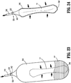
- a pull string 870 ( FIG. 32 ) and/or a grasper 880 ( FIG. 33 ) is utilized to pull specimen bag 840 proximally into longitudinal passageway 824 of tubular body 822 of inner cannula 820.
- inner cannula 820 is rotated relative to specimen bag 840 and outer cannula 810 in a direction corresponding to the direction of pitch of threading 832.
- threading 832 provides torsional urging to feed specimen bag 840 proximally through longitudinal passageway 824 of tubular body 822 of inner cannula 820, thus facilitate withdrawal of specimen bag 840 and the tissue "T" therein from the internal surgical site.
- mouth 842 of specimen bag 840 may be exteriorized and outer and inner cannulas 810, 820 may be inserted into specimen bag 840 allowing tissue "T," while isolated from surrounding tissue, to be fed proximally through longitudinal passageway 824 of tubular body 822 of inner cannula 820 and removed from the internal surgical site.
- specimen bag 840 may be exteriorized through outer cannula 810 with inner cannula 820 inserted into specimen bag 840 allowing tissue "T" to be fed proximally through longitudinal passageway 824 of tubular body 822 of inner cannula 820 and removed from the internal surgical site.
- specimen retrieval system 900 includes a cannula 910, a funnel 920, and a gear system 930 that may be utilized to facilitate removal of a specimen, e.g., tissue "T," enclosed within a specimen bag 940 from an internal surgical site.
- specimen bag 940 is included as part of specimen retrieval system 900; in other embodiments, specimen bag 940 is separate therefrom enabling use of specimen retrieval system 900 with any other suitable specimen bag or without a specimen bag.
- cannula 910 of specimen retrieval system 900 includes a tubular body 912 defining a longitudinal passageway 914 extending therethrough.
- Tubular body 912 is configured for insertion through an opening in tissue and into an internal surgical site.
- Funnel 920 of specimen retrieval system 900 includes a cylindrical proximal portion 922 and a conical distal portion 924 that extends distally from cylindrical proximal base 922 increasing in diameter in a proximal-to-distal direction.
- Funnel 920 is slidably disposed about tubular body 912 of cannula 910.
- Funnel 920 may be formed from a flexible material enabling flexion of funnel 920 to enable insertion through an opening in tissue and into an internal surgical site.
- funnel 920 may include first and second components, e.g., halves, that are releasably engaged with one another such that the components may be inserted through an opening in tissue and into an internal surgical site separately and then engaged with one another to form funnel 920.
- funnel 920 may be configured to pivot relative to cannula 910 and/or may include portions configured to pivot and/or slide relative to one another to facilitate insertion through an opening in tissue and into an internal surgical site.
- Other configurations, including combinations of the above, enabling insertion of funnel 920 through an opening in tissue and into an internal surgical site are also contemplated.
- Gear system 930 includes at least one rack 932 disposed on, e.g., formed with, adhered to, mechanically engaged with, etc., and extending longitudinally along an outer surface of tubular body 912 of cannula 910.
- a pair of spaced-apart and parallel racks 932 extends longitudinally along the outer surface of tubular body 912 of cannula 910.
- Gear assembly 930 further includes an axle 934 rotatably mounted on and/or within cylindrical proximal base 922 of funnel 920 with at least one end portion of axle 934 extending outwardly from cylindrical proximal base 922 of funnel 920. In embodiments, both end portions of axle 934 extend from funnel 920.
- At least one gear 936 is mounted on the at least one end portion of axle 934 and disposed in meshed engagement with the at least one rack 932.
- gear assembly 930 further includes at least one ratchet assembly 938 having a spring-loaded ratchet gear 939 mounted on the at least one end portion of axle 934 and a ratchet pawl (not shown) operably positioned relative to the ratchet gear 939.
- Gear assembly 930 may additionally include a release (not shown), e.g., a push-button, lever, etc., configured to disengage ratchet gear 939 from the ratchet pawl.
- FIGS. 35-37 illustrate use of specimen retrieval system 900.
- specimen bag 940 is deployed within an internal surgical site and a specimen, e.g., tissue "T," is loaded into specimen bag 940.
- cannula 910 and funnel 920 are inserted into the internal surgical site (together with one another or separately and then engaged with one another) and through mouth 942 of specimen bag 940 such that at least a portion of cannula 910 and funnel 920 are disposed within the interior of specimen bag 940.
- funnel 920 is then slid distally about cannula 910 towards tissue "T.”
- the meshed engagement between gears 936 and racks 932 drives rotation of gears 936 and, thus, rotation of axle 934.
- Rotation of axle 934 rotates ratchet gears 939 relative to the corresponding ratchet pawls (not shown) to incrementally lock funnel 920 in position, inhibiting proximal return of funnel 920.
- funnel 920 may be slid distally about cannula 910 to compress tissue "T” and, when released, locks into position relative to cannula 910.
- tissue "T” is not compressed but, rather, funnel 920 is slid distally into position adjacent tissue "T.”
- a grasper 980 may be utilized to pull tissue "T" proximally through funnel 920 and cannula 910.
- the cone-shaped configuration of conical distal portion 924 of funnel 920 facilitates withdrawal of tissue "T” by directing tissue "T” radially inwardly in a gradual manner, thus reducing the force required for withdrawal.
- specimen bag 940 As an alternative to inserting cannula 910 and funnel 920 into specimen bag 940, specimen bag 940, along with tissue "T" therein, may together be withdrawn through funnel 920 and cannula 910 in a similar manner as detailed above.
- pull string 970 FIG. 35
- specimen bag 940 may be utilized to facilitate withdrawal.
- racks 932 may be disposed on, e.g., formed with, adhered to, mechanically engaged with, etc., and extend longitudinally along outer surfaces of specimen bag 940 on opposing sides thereof.
- the ratcheting components associated with funnel 920 may be configured to enable proximal withdrawal of specimen bag 940 (including tissue "T" therein) through funnel 920 while locking to inhibit distal return of specimen bag 940 through funnel 920.
- specimen bag 940 (including tissue “T” therein) may be incrementally (via ratcheting) drawn proximally through funnel 920 (and/or funnel 920 advanced distally over specimen bag 940) to facilitate withdrawal of specimen bag 940 and tissue "T," similarly as detailed above with respect to cannula 910 and funnel 920.
- conical distal portion 924 of funnel 920 facilitates withdrawal of specimen bag 940 and tissue "T” by urging specimen bag 940 and tissue "T” radially inwardly in a gradual manner as specimen bag 940 is withdrawn through funnel 920, thus reducing the force required for withdrawal.
- the ratcheting engagement between specimen bag 940 and funnel 920 also facilitates this withdrawal.
- Cannula 910 may be omitted in such configurations or may be utilized in conjunction with specimen bag 940.
Landscapes
- Health & Medical Sciences (AREA)
- Life Sciences & Earth Sciences (AREA)
- Surgery (AREA)
- Heart & Thoracic Surgery (AREA)
- Engineering & Computer Science (AREA)
- Biomedical Technology (AREA)
- Nuclear Medicine, Radiotherapy & Molecular Imaging (AREA)
- Medical Informatics (AREA)
- Molecular Biology (AREA)
- Animal Behavior & Ethology (AREA)
- General Health & Medical Sciences (AREA)
- Public Health (AREA)
- Veterinary Medicine (AREA)
- Surgical Instruments (AREA)
- Sampling And Sample Adjustment (AREA)
Abstract

Description
- This application claims the benefit of, and priority to,
U.S. Provisional Patent Application No. 62/968,395, filed on January 31, 2020 U.S. Provisional Patent Application No. 63/120,435, filed on December 2, 2020 - This disclosure is generally related to specimen retrieval and, more particularly, to devices, systems, and methods facilitating removal of a specimen from an internal body cavity
- When removing certain specimen from an internal body cavity, e.g., diseased tissue, it may be desirable to inhibit contact between the specimen and surrounding tissue. In order to help protect surrounding tissue, specimen bags have been developed and utilized for deployment into an internal body cavity, loading of the specimen therein, and isolated removal of the specimen, thereby inhibiting contact between the specimen and surrounding tissue.
- This disclosure generally relates to specimen retrieval bags, specimen retrieval devices, specimen retrieval systems, and specimen retrieval methods configured to facilitate the isolated removal of a specimen from an internal body cavity such as, for example, during a minimally invasive surgical procedure.
- A specimen retrieval device in accordance with aspects includes a tubular body having a proximal portion and a distal portion and defining a longitudinal lumen therethrough, an inner shaft slidably disposed within the longitudinal lumen of the tubular body, and a specimen bag. The inner shaft has a proximal portion, a distal portion, and a support member extending from the distal portion thereof. The specimen bag is supported on the support member of the inner shaft and includes a bag body having an open end connected to the support member of the inner shaft. The bag body defines a longitudinal axis. The specimen bag further includes a plurality of ribs connected to the bag body such that a respective longitudinal axis thereof is substantially parallel with the longitudinal axis of the bag body. The inner shaft is movable in relation to the tubular body from a first position wherein the support member and the specimen bag are disposed within the longitudinal lumen of the tubular body to a second position wherein at least a portion of the support member and the specimen bag are deployed externally of the tubular body.
- In an aspect, the specimen bag includes a pull string including a distal portion threaded through the plurality of ribs and a proximal portion extending proximally from the distal through the tubular body.
- In another aspect, the distal portion of the pull string winds around a circumference of the bag body of the specimen bag, from a location near the open end of the bag body to a location near a closed end of the bag body.
- In another aspect, the distal portion of the pull string winds around the bag body in a helical manner through the plurality of ribs.
- In still another aspect, a distal end of the distal portion of the pull string includes a stop member preventing the distal end portion of the pull string from being pulled out of a rib.
- In yet another aspect, each rib includes at least one eyelet through which the distal portion of the pull string passes.
- In still yet another aspect, each rib is linear.
- In another aspect, the pull string is a first pull string and the specimen bag includes a second pull string including a distal portion threaded about the open end of the bag body and a proximal portion extending from the proximal portion of the tubular body.
- In another aspect, the support member includes a pair of resilient fingers which support the specimen bag thereon and open the open end of the bag body in the second position.
- Another specimen retrieval device in accordance with aspects includes a tubular body having a proximal portion and a distal portion and defining a longitudinal lumen therethrough, an inner shaft slidably disposed within the longitudinal lumen of the tubular body, and a specimen bag. The inner shaft has a proximal portion, a distal portion, and a support member connected to a distal end of the distal portion thereof. The specimen bag is supported on the support member of the inner shaft and includes a bag body having an open end connected to the support member of the inner shaft. The bag body defines a longitudinal axis. The specimen bag further includes a plurality of ribs connected to the bag body such that a respective longitudinal axis of each rib is substantially parallel with the longitudinal axis of the bag body, and a pull string. The pull string includes a distal portion slidably connected to the plurality of ribs and a proximal portion extending from the proximal portion of the tubular body. The inner shaft is movable in relation to the tubular body from a first position wherein the support member and the specimen bag are disposed within the longitudinal lumen of the tubular body to a second position wherein at least a portion of the support member and the specimen bag are deployed externally of the tubular body. In the second position, the bag body is free to expand to a maximum radial dimension thereof. The pull string is actuatable to radially constrict the radial dimension of the bag body by drawing the plurality of ribs radially inwardly towards the longitudinal axis of the bag body.
- In an aspect, the distal portion of the pull string winds around a circumference of the bag body of the specimen bag, from a location near the open end of the bag body to a location near a closed end of the bag body.
- In another aspect, the distal portion of the pull string winds around the bag body in a helical manner through the plurality of ribs.
- In still another aspect, a distal end of the distal portion of the pull string includes a stop member preventing the distal end portion of the pull string from being pulled out of a rib.
- In yet another aspect, each rib includes at least one eyelet through which the distal portion of the pull string passes.
- Each rib, in aspects, may be linear.
- In still yet another aspect, the pull string is a first pull string and the specimen bag includes a second pull string including a distal portion threaded about the open end of the bag body and a proximal portion extending from the proximal portion of the tubular body.
- In yet another aspect, the support member includes a pair of resilient fingers which support the bag body of the specimen bag and open the open end of the bag body in the second position.
- A specimen bag provided in accordance with aspects includes a bag body having an open end and defining a longitudinal axis, a plurality of ribs connected to the bag body such that a respective longitudinal axis of each rib is substantially parallel with the longitudinal axis of the bag body, and a pull string. The pull string includes a distal portion slidably connected to the plurality of ribs, a proximal portion extending proximally from the distal portion to enable selective actuation thereof, and a stop member connected to a distal end of the pull string. The stop member prevents the distal end portion of the pull string from being pulled out of a rib. In an initial condition, the bag body is free to expand to a maximum radial dimension thereof. The pull string is actuatable to radially constrict the radial dimension of the bag body from the initial condition by drawing the distal portion of the pull string through the plurality of ribs to draw the plurality of ribs radially inwardly towards the longitudinal axis of the bag body.
- In an aspect, the distal portion of the pull string winds around the bag body in a helical manner through the plurality of ribs. Additionally or alternatively, each rib is linear.
- Another specimen bag in accordance with aspects includes a bag body and a suction tube wound about the bag body in a helical pattern. When suction is applied through the suction tube, a diameter of the helix defined by the suction tube is reduced, thereby constricting the specimen bag and compressing a specimen disposed therein.
- In accordance with still other aspects of the disclosure, a specimen retrieval system is provided including an outer cannula and an inner cannula. The outer cannula includes a first tubular body having a first inner surface defining a first longitudinal passageway. The first tubular body is configured for positioning within an opening in tissue. The inner cannula includes a second tubular body having a second inner surface defining a second longitudinal passageway. The second tubular body is positionable within the first longitudinal passageway and rotatable relative thereto. The second inner surface includes helical threading configured to facilitate feeding tissue proximally through the second longitudinal passageway upon rotation of the inner cannula relative to the outer cannula.
- In an aspect of the disclosure, the helical threading protrudes from the second inner surface. Alternatively, the helical threading may be recessed into the second inner surface.
- In another aspect of the disclosure, the outer cannula further includes a proximal hub disposed at a proximal end portion of the first tubular body. Additionally or alternatively, the inner cannula further includes a proximal hub disposed at a proximal end portion of the second tubular body.
- In yet another aspect of the disclosure, the first inner surface and an outer surface of the second tubular body are smooth to facilitate relative rotation between the first and second tubular bodies.
- In still another aspect of the disclosure, the system further includes a grasper configured for insertion through the second longitudinal passageway and to draw tissue proximally through the second longitudinal passageway. In aspects, the inner cannula is configured to rotate relative to the grasper.
- In still yet another aspect of the disclosure, the system further includes a specimen bag. In aspects, the specimen bag is configured to receive tissue therein and to be withdrawn through the second longitudinal passageway along with tissue received therein. In other aspects, the outer and inner cannulas are configured for positioning within the specimen bag to enable withdrawal of tissue within the specimen bag proximally through the second longitudinal passageway. In still other aspects, the outer cannula is configured to revive the specimen bag through the first longitudinal passageway and the inner cannula is configured for positioning within the specimen bag to enable withdrawal of tissue within the specimen bag proximally through the second longitudinal passageway.
- Yet another specimen retrieval system provided in accordance with aspects of the disclosure includes a specimen bag including a bag body and a biaxial structure, and an insert. The biaxial structure is transitionable between a first condition wherein the specimen bag defines a longitudinally compressed and radially expanded configuration, and a second condition, wherein the specimen bag defines a longitudinally expanded and radially compressed configuration. The insert is positionable within the specimen bag and configured to maintain at least a portion of the biaxial structure in the first condition.
- In an aspect of the disclosure, the biaxial structure is biased towards the first condition. Alternatively, the biaxial structure may be biased towards the second condition.
- In another aspect of the disclosure, the specimen bag further includes a reinforcement ring surrounding a mouth of the bag body, e.g., to maintain the open mouth in an open condition.
- In yet another aspect of the disclosure, the bag body is configured to stretch to accommodate transitioning of the biaxial structure between the first and second conditions.
- In still another aspect of the disclosure, the insert includes a plurality of fingers extending from a common end portion. Alternatively, the insert may include a plurality of fingers extending from a base ring. In either aspect, the insert may be compressible from an initial condition to a compressed condition.
- In still yet another aspect of the present disclosure, the biaxial structure is disposed within the bag body. Alternatively, the biaxial structure may be disposed about the bag body.
- Another specimen retrieval system provided in accordance with aspects of the disclosure includes a plurality of rods configured for insertion through an opening in tissue and arrangement to define a longitudinal passageway through the opening in tissue. The system further includes at least one collar configured for slidable positioning about the plurality of rods to maintain the longitudinal passageway. Each of the at least one collars defines a central opening in communication with the longitudinal passageway to enable withdrawal of tissue through the longitudinal passageway and each central opening.
- In an aspect of the disclosure, the at least one collar is configured for sliding about the plurality of rods through the opening in tissue.
- In another aspect of the disclosure, the at least one collar includes a plurality of collars configured for spaced-apart positioning along at least a portion of a length of the plurality of rods.
- In yet another aspect of the disclosure, each of the at least one collars defines a plurality of discrete openings. Each discrete opening is configured to slidably receive one of the rods of the plurality of rods. The discrete openings may be slots to enable the rods to slide along the respective slots to permit repositioning of the rods relative to one another.
- In still another aspect of the disclosure, each of the rods defines a stop at a distal end thereof to inhibit the at least one collar from sliding distally off of the rods.
- In still yet another aspect of the disclosure, the central opening defines a non-circular cross-section, e.g., a triangular cross-section.
- In another aspect of the disclosure, each collar defines a cylindrical disc-shape.
- In aspects, the system may further include a specimen bag configured for positioning within an internal surgical site. The specimen bag is configured to be pulled through the longitudinal passageway and each central opening to enable withdrawal of the specimen bag from the internal surgical site.
- In aspects, a pull-string is connected to the specimen bag towards an open end thereof and configured to facilitate pulling the specimen bag.
- Still another specimen retrieval system, and an associated method, in accordance with aspects includes a tube, a specimen bag, a connector connecting the tube with the specimen bag (permanently or releasably), and a pump and suction source. With a specimen disposed within the specimen bag and the specimen bag closed, the pump and suction source is activated in a pump mode to pump fluid through the tube and into the specimen bag, thereby compressing a specimen therein to squeeze fluids out of the specimen. The pump and suction source is then activated in a suction mode to suction out the fluid from the specimen bag through the tube. The reduced-volume (as a result of the squeezed and removed fluid) specimen within the specimen bag can then be more readily removed via removal of the specimen bag.
- Still another specimen bag in accordance with aspects includes a bag body and a tie arrangement disposed on, within, and/or integrated into the bag body. The tie arrangement includes at least one strand of material forming a netting having an initial, first condition having a first diameter. In response to a longitudinal pulling force applied to one of the strands of the tie arrangement, the netting transitions to a second condition, wherein the netting has a second, smaller diameter such that the specimen bag is constricted, thereby compressing a specimen disposed therein.
- A method of specimen removal in accordance with aspects includes positioning a specimen within a specimen bag, tightening a pull string about a portion of the specimen bag having a portion of the specimen therein such that the pull string grasps the portion of the specimen bag and the portion of the specimen, and pulling the pull string to withdraw the specimen bag, with the specimen therein, from an internal body cavity.
- Still yet another specimen retrieval system in accordance with aspects includes a cannula, a funnel, and a gear assembly. The gear assembly operably couples the funnel about the cannula to enable ratcheted distal sliding of the funnel about the cannula, e.g., to compress a specimen within a distal cone portion of the funnel. The specimen may be removed through the funnel and the cannula, wherein the distal cone portion of the funnel reduces withdrawal forces. The specimen may be removed itself (e.g., wherein the specimen retrieval system is inserted into a specimen bag containing the specimen) or may be removed through the funnel and cannula together with a specimen bag retaining the specimen therein.
- Another specimen retrieval system in accordance with aspects includes a specimen bag configured for positioning within an internal surgical site and a body. The specimen bag includes an open end and a closed end and has first and second racks disposed on an outer surface thereof on opposing sides thereof. The body includes a ratchet assembly having first and second ratchet gears. The specimen bag is configured for passage through the body such that the first and second racks engage the first and second ratchet gears to enable ratcheted passage of the specimen back through the body.
- The details of one or more aspects of the disclosure are set forth in the accompanying drawings and the description below. Other features, objects, and advantages of the disclosure will be apparent from the description and drawings, and from the claims.
-
-
FIG. 1 is a perspective view of a specimen retrieval device disposed in a deployed condition; -
FIG. 2 is a perspective view, with parts separated, of the specimen retrieval device ofFIG. 1 ; -
FIG. 3 is an enlarged, perspective view of the area of detail indicated as "3" inFIG. 1 , illustrating a specimen bag of the specimen retrieval device ofFIG. 1 , disposed in an expanded condition; -
FIG. 4 is a perspective view of the specimen bag ofFIG. 3 disposed in the expanded condition; -
FIG. 5 is an enlarged, side view of the specimen bag ofFIG. 3 disposed in a contracted condition; -
FIG. 6 is a greatly enlarged, side view of a portion of the specimen bag ofFIG. 3 ; -
FIG. 7 is an enlarged, perspective view of the area of detail indicated as "7" inFIG. 1 ; -
FIG. 8 is a perspective view of the specimen retrieval device ofFIG. 1 disposed in a first partially-retracted condition; and -
FIG. 9 is a perspective view of the specimen retrieval device ofFIG. 1 disposed in a second partially-retracted condition; -
FIG. 10 is a perspective view of another specimen bag configured for use with the specimen retrieval device ofFIG. 1 , any other suitable specimen retrieval device, or as a standalone specimen bag, disposed in an expanded condition; -
FIG. 11 is a perspective view of the specimen bag ofFIG. 10 , disposed in a contracted condition; -
FIG. 12 is an exploded, perspective view of another specimen bag configured for use with the specimen retrieval device ofFIG. 1 , any other suitable specimen retrieval device, or as a standalone specimen bag, disposed in an expanded condition; -
FIG. 13A is a perspective view of the specimen bag ofFIG. 12 , disposed in an expanded condition; and -
FIG. 13B is a perspective view of the specimen bag ofFIG. 12 , disposed in a contracted condition; -
FIG. 13C is a perspective view of another configuration of the specimen bag ofFIG. 12 , disposed in the contracted condition; -
FIG. 14 is a side view of another specimen bag, disposed in a contracted condition; -
FIG. 15 is a side view of an insert configured for use with the specimen bag ofFIG. 14 ; -
FIG. 16 is a side view illustrating the insert ofFIG. 15 disposed within the specimen bag ofFIG. 14 to retain the specimen bag in an expanded condition; -
FIG. 17 is a side view of the specimen bag ofFIG. 14 in the contracted condition retaining tissue therein; -
FIG. 18 is a perspective view illustrating another specimen retrieval device in use within an internal body cavity; -
FIG. 19 is a transverse, cross-sectional view taken across section line 19-19 ofFIG. 18 ; -
FIGS. 20 and21 are perspective views progressively illustrating the specimen retrieval device ofFIG. 18 in use removing tissue from the internal body cavity; -
FIG. 22 is a side view of a specimen retrieval system in use within an internal body cavity; -
FIG. 23 is an enlarged, perspective view of a specimen bag of the specimen retrieval system ofFIG. 22 , disposed in an expanded condition; -
FIG. 24 is an enlarged, perspective view of the specimen bag of the specimen retrieval system ofFIG. 22 , disposed in a contracted condition; -
FIG. 25 is a side view illustrating the specimen retrieval system ofFIG. 22 in use removing tissue from the internal body cavity; -
FIG. 26 is a perspective view of yet another specimen bag configured for use with the specimen retrieval device ofFIG. 1 , any other suitable specimen retrieval device, or as a standalone specimen bag, disposed in an expanded condition; -
FIG. 27 is a perspective view of the specimen bag ofFIG. 26 , disposed in a contracted condition; -
FIG. 28 is a side view illustrating removal of tissue disposed within a specimen bag in a first manner; -
FIG. 29 is a side view illustrating removal of tissue disposed within a specimen bag in a second, different manner; -
FIG. 30 is a perspective view of a cannula assembly configured to facilitate withdrawal of a tissue containing specimen bag therethrough; -
FIG. 31 is a perspective view, with parts separated, of the cannula assembly ofFIG. 30 ; -
FIGS. 32 and33 are partial cross-sectional views progressively illustrating withdrawal of the tissue containing specimen bag through the cannula assembly ofFIG. 30 ; -
FIG. 34 is a perspective view of a portion of another cannula assembly configured to facilitate withdrawal of a tissue containing specimen bag therethrough; -
FIG. 35 is a perspective view of the cannula assembly ofFIG. 34 disposed within the tissue containing specimen bag; -
FIGS. 36 and 37 are cross-sectional view progressively illustrating use of the cannula assembly ofFIG. 34 for withdrawing the tissue from the specimen bag; and -
FIG. 38 is a perspective view of another specimen bag configured for use with the funnel of the cannula assembly ofFIGS. 34-37 . - This disclosure provides devices, systems, and methods facilitating removal of a specimen from an internal body cavity such as, for example, for use in minimally invasive surgical procedures including but not limited to laparoscopic procedures, arthroscopic procedures, endoscopic procedures, natural orifice transluminal endoscopic surgical (NOTES) procedures, etc.
- Referring to
FIGS. 1 and2 , aspecimen retrieval device 10 includes atubular body 12 having aproximal portion 16 and adistal portion 18, and defining alongitudinal lumen 14 that extends betweenproximal portion 16 anddistal portion 18.Proximal portion 16 oftubular body 12 supports ahand grip 15.Specimen retrieval device 10 also includes aninner shaft assembly 20 having aninner shaft 22 slidably positioned withinlongitudinal lumen 14 oftubular body 12, anactuation handle 25 secured to aproximal portion 24 ofinner shaft 22, and aspecimen bag 40 supported on adistal portion 26 ofinner shaft 22.Tubular body 12 andinner shaft 22 define a common longitudinal axis "X." -
Hand grip 15 and actuation handle 25 are configured for concomitant and relative manipulation to facilitate manipulation ofspecimen retrieval device 10 and the sliding ofinner shaft 22 withintubular body 12. More specifically,hand grip 15 and actuation handle 25 can be moved together to manipulatespecimen retrieval device 10 to a desired position and, thereafter,hand grip 15 can be grasped with one hand and actuation handle 25 can be grasped with the other hand to affect relative movement therebetween to moveinner shaft 22 withintubular body 12. -
Distal portion 26 ofinner shaft 22 is coupled to asupport member 28 that is configured to support amouth 42 of aspecimen bag 40.Support member 28 includes a pair ofresilient fingers distal portion 26 ofinner shaft 22.Resilient fingers distal portion 26 ofinner shaft 22 such as by molding. Alternatively, a retention pin (not shown) or other suitable attachment mechanism may be used to attachresilient fingers distal portion 26 ofinner shaft 22.Resilient fingers FIG. 1 ) such as, for example, to enable placement and retention ofresilient fingers specimen bag 40 withintubular body 12.Resilient fingers tubular body 12 to thereby deployspecimen bag 40 andpresent mouth 42 ofspecimen bag 40, as described below. -
Specimen bag 40 includes abag body 44 having a generally tubular, elongated sock-like configuration that is defined by an openable andclosable mouth 42 and a closed end 46 (FIG. 1 ).Mouth 42 defines anopening 45. In embodiments,specimen bag 40 includes a tail 48 (FIG. 2 ) having aneck region 47 defined along longitudinal axis "X" whilebag body 44 ofspecimen bag 40 defines a longitudinal axis "Y" (FIG. 2 ) disposed at an angle relative to longitudinal axis "X." - With continued reference to
FIGS. 1 and2 ,bag body 44 defines a maximum radial dimension sufficient for receiving and containing a tissue specimen therein and may be made from any suitable biocompatible material (e.g., nylon, urethane, ripstop nylon, latex, etc.) capable of forming a flexible collapsible membrane. In embodiments, portions ofspecimen bag 40 are made of two different materials (e.g., two different nylons) secured together to form areas ofspecimen bag 40 having high strength. -
Mouth 42 ofspecimen bag 40 is releasably connected toresilient fingers inner shaft 22 such as, for example, via recite ofresilient fingers more cuff 43 defined aboutmouth 42 ofspecimen bag 40. -
Specimen retrieval device 10 further includes apull string 70 having a distal portion attached to and encirclingmouth 42 ofspecimen bag 40. In embodiments,resilient fingers string 70 may both be received in the one ormore cuffs 43 ofspecimen bag 40, or may be received withinseparate cuffs 43 or other suitable retaining structures defined aboutmouth 42 ofspecimen bag 40. - Referring also to
FIG. 7 , aproximal portion 72 ofpull string 70 may be in the form of aloop 74 to assist in pullingpull string 70, thereby tightening the distal portion ofpull string 70 and, in turn, closingmouth 42 ofspecimen bag 40. -
FIGS. 2-6 illustratespecimen bag 40, which includes a plurality ofribs 60 connected tobag body 44.Ribs 60 are disposed radially aboutbag body 44.Ribs 60 are oriented such that longitudinal axes thereof are substantially parallel with longitudinal axis "Y" ofbag body 44. In embodiments, the longitudinal axes ofribs 60 may be parallel to longitudinal axis "Y" of the bag body 44 (e.g., having a zero degree (0°) orientation angle therebetween), or may define orientation angles of up to about 45° therebetween. -
Ribs 60 may be located externally ofbag body 44, internally ofbag body 44 or interposed between layers of material formingbag body 44, either entirely or partially, or any combination thereof. Further, whilelinear ribs 60 are shown and described, it is contemplated thatribs 60 may be angled or define a helical or curved configuration. The configuration, number, and a dimensions ofribs 60 are selected such thatspecimen bag 40 may be sufficiently collapsed to reside withinlumen 14 oftubular body 12. In embodiments,ribs 60 are substantially rigid to resist bending and deformation. - With additional reference to
FIG. 7 ,specimen bag 40 further includes apull string 62 having adistal portion 63 threaded through plurality ofribs 60 in a helical pattern aboutbag body 44 ofspecimen bag 40 to encirclebag body 44 ofspecimen bag 40. More specifically, pullstring 62 slidably passes throughapertures 61 defined through eachrib 60. A distal-most end ofpull string 62 may be provided with astop member 64, e.g., a knot, enlarged head, etc., which prevents withdrawal of the distal-most end ofpull string 62 from within thelast rib 60. While asingle pull string 62 is shown and described, it is contemplated that any number of pullstrings 62 may be provided, and may wrap aroundbag body 44 and throughribs 60 in one or more directions (e.g., a crisscrossing helical pattern) to facilitate constrictingbag body 44 andribs 60 radially inward along an entire length ofbag body 44 ofspecimen bag 40 when the pull string(s) 62 is are pulled proximally. - Referring to
FIGS. 1 ,2 ,8 and9 , in use,tubular body 12 ofspecimen retrieval device 10 is inserted into an internal surgical site withspecimen bag 40 positioned withintubular body 12, e.g., furled aboutinner shaft 22 or disposed distally thereof. When it is desired to deployspecimen bag 40 within the internal surgical site, actuation handle 25 is pushed distally relative tohand grip 15 such thatdistal portion 26 ofinner shaft 22 urgesspecimen bag 40 to exitdistal portion 18 oftubular body 12. - Once
specimen bag 40 has exitedtubular body 12,resilient fingers mouth 42 ofspecimen bag 40 to ensurespecimen bag 40 is deployed. Asmouth 42 ofspecimen bag 40 is opened, and due tobag body 44 ofspecimen bag 40 being free oftubular body 12, a specimen may be introduced intobag body 44 ofspecimen bag 40 through opening 45 ofmouth 42. - As depicted in
FIG. 8 , after a specimen, e.g., tissue "T," has been placed inspecimen bag 40, pullstring 70 is pulled proximally (indicated by arrows "A" inFIG. 8 ), thus closingmouth 42 ofspecimen bag 40 and withdrawing a portion ofspecimen bag 40 intotubular body 12. Aftermouth 42 is closed, as depicted inFIG. 9 , pullstring 62 is pulled proximally (indicated by arrows "A" inFIG. 9 ), thus pullingdistal portion 63 ofpull string 62 throughribs 60 to radially inwardly contract and approximate ribs 50. As a result,bag body 44 ofspecimen bag 40 is compressed, thereby reducing a transverse cross-sectional dimension ofspecimen bag 40, including tissue "T" therein. The orientation ofribs 60 and positioning thereof aboutbag body 44, together with the arrangement ofpull string 62 relative toribs 60 provides uniform compression about tissue "T" whenpull string 62 is pulled proximally. - With
specimen bag 40 retaining tissue "T" therein and disposed in a closed and contracted condition,tail 48 ofspecimen bag 40 and/orinner shaft 22 may be withdrawn proximally to withdrawspecimen bag 40 from the body cavity throughlumen 14 oftubular body 12 or together therewith. - Turning to
FIGS. 10 and 11 , anotherspecimen bag 140 configured for use with specimen retrieval device 10 (FIG. 1 ), any other suitable specimen retrieval device, or as a standalone specimen bag is shown.Specimen bag 140 may include any of the features of specimen bag 40 (FIGS. 1-6 ) except that, rather than includingribs 60 and apull string 62 as specimen bag 40 (seeFIGS. 2-4 ),specimen bag 140 includes asuction tube 160. However, it is also contemplated thatspecimen bag 140 include bothsuction tube 160 and ribs similar to ribs 60 (FIGS. 2-4 ). -
Suction tube 160 may be disposed externally ofbag body 144 ofspecimen bag 140, internally ofbag body 144 or interposed between layers of material formingbag body 144, either entirely or partially, or any combination thereof.Suction tube 160 includes ahelical body 162 that defines a helical configuration extending aboutbag body 144.Suction tube 160 further includes aproximal extension 164 that extends fromhelical body 162 andbag body 144, e.g., proximally through tubular body 12 (FIG. 1 ), to connect to a source of suction (not shown). -
FIG. 10 illustratesspecimen bag 140 in an expanded condition prior to activation of suction. As shown inFIG. 11 , upon activation of suction throughsuction tube 160,helical body 162 is contracted radially inwardly to thereby compressbag body 144 and any tissue "T" withinbag body 144 radially inwardly, reducing a transverse cross-sectional dimension ofspecimen bag 140 to facilitate removal from an internal surgical site. - The helical configuration of
suction tube 160 provides radial inward compression about the entire circumference ofbag body 144, thus providing more uniform compression about tissue "T." In embodiments,multiple suction tubes 160 are provided, e.g., twosuction tubes 160 defining a double helix, to further facilitate uniform compression about tissue "T." - Referring to
FIGS. 12 ,13A , and13B , still anotherspecimen bag 240 configured for use with specimen retrieval device 10 (FIG. 1 ), any other suitable specimen retrieval device, or as a standalone specimen bag is shown.Specimen bag 240 may include any of the features ofspecimen bags 40, 140 (FIGS. 1-6 and10-11 , respectively) except that, rather than includingribs 60 and apull string 62 as specimen bag 40 (seeFIGS. 2-4 ) or asuction tube 160 as specimen bag 140 (FIGS. 10 and 11 ),specimen bag 240 includes abiaxial structure 242. -
Specimen bag 240, more specifically, includes abiaxial structure 242 and aflexible bag body 244. Aninsert 250 may also be configured for use withspecimen bag 240 for, as detailed below, maintaining at least a portion ofspecimen bag 240 in an expanded condition.Flexible bag body 244 may be formed from any suitable flexible and/or stretchable material capable of flexing and/or stretching in connection with manipulation ofbiaxial structure 242. Suitable materials include, for example, nylon. In embodiments, insert 250 may be replaced with insert 350 (FIG. 15 ) or both insert 250 and insert 350 (FIG. 15 ) may be utilized. - The
biaxial structure 242 ofspecimen bag 240 may be a biaxial braid of material or other suitable structure biased to define a first length and a first diameter that, when a tension force, e.g., a longitudinal pulling force, is applied thereto, is compressed radially inwardly and elongated longitudinally to define a second length greater than the first length and a second diameter smaller than the first diameter. On the other hand, when a compression force, e.g., a longitudinal pushing forceps, is applied thereto, thebiaxial structure 242 is expanded radially outwardly and compressed longitudinally to define a third length smaller than the first length and a third diameter greater than the first diameter.Biaxial structure 242 may be disposed externally ofbag body 244, internally ofbag body 244, or interposed between layers of material formingbag body 244, either entirely or partially, or any combination thereof. -
Insert 250 may define a generally semi-spherical configuration or other suitable configuration and is formed from a plurality offingers 254.Fingers 254 are attached to one another at acommon end 252.Fingers 254 extend fromcommon end 252 in an arcuate, spaced-apart manner to define the semi-spherical configuration ofinsert 250.Insert 250 may be monolithically formed from a single piece of material or the plurality offingers 254 may be separately formed and then joined with one another, e.g., via welding atcommon end 252.Fingers 254 may be formed from nitinol or other suitable material providing sufficient structural strength to overcome the bias ofbiaxial structure 242 ofspecimen bag 240 to expand and maintain at least a portion ofbiaxial structure 242 in an increased-diameter configuration wheninsert 250 is disposed therein. Thematerial forming fingers 254 is also sufficiently flexible to enable collapse for withdrawal, e.g., asspecimen bag 240 is withdrawn into tubular body 12 (FIG. 1 ). -
FIG. 13A illustratesspecimen bag 240 in an expanded (radial) condition.Specimen bag 240 may be disposed in an at-rest condition, e.g., where no longitudinal force is applied thereto, to enable loading of tissue "T" therein, or a longitudinal pushing force may be applied to radially expandbiaxial structure 242, thus enlarging the radial dimension ofspecimen bag 240, to enable loading of tissue "T" therein. In either configuration, insert 250 may be inserted intospecimen bag 240 prior to loading of tissue "T" and positioned at the closed end ofbag body 244 to maintain at least a portion ofbag body 244 adjacent the closed end thereof in an expanded condition, thus facilitating loading of tissue "T" intospecimen bag 240. - As shown in
FIG. 13B , upon application of a longitudinal pulling force tospecimen bag 240, e.g., to retractspecimen bag 240 into tubular body 12 (FIG. 1 ),biaxial structure 242 is elongated and compressed radially inwardly to thereby compressbag body 244 and any tissue "T" withinbag body 244 radially inwardly, reducing a transverse cross-sectional dimension ofspecimen bag 240 to facilitate removal from an internal surgical site. The longitudinal pulling force may be sufficient to collapseinsert 250 inwardly to reduce the cross-sectional dimension thereof to facilitate removal. Alternatively, insert 250 may be removed fromspecimen bag 240 after loading of tissue "T" and prior to compression ofspecimen bag 240. - As shown in
FIGS. 13A and13B , the closed end ofbag body 244 defines a convex configuration and/or insert 250 is positioned withinspecimen bag 240 adjacent the closed end thereof in an orientation that maintains a convex configuration of the closed end ofbag body 244. Alternatively, as shown inFIG. 13C , the closed end ofbag body 244 may define a concave configuration and/or insert 250 may be positioned withinspecimen bag 240 adjacent the closed end thereof in an orientation that maintains a concave configuration of the closed end ofbag body 244. Other configurations are also contemplated. - With reference to
FIGS. 14-17 aspecimen retrieval system 300 is provided including aspecimen bag 340 and aninsert 350. Initially referring toFIG. 14 ,specimen bag 340 includes abag body 344 having a generally tubular, elongated sock-like configuration that is defined by an openable andclosable mouth 342 and aclosed end 346.Mouth 342 defines anopening 345 that may be opened and closed in any suitable manner, e.g., similarly as detailed above with respect to specimen bag 40 (FIGS. 2-4 ).Specimen bag 340 may be formed from any suitable material such as those detailed above with respect to specimen bag 40 (FIGS. 2-4 ). -
Specimen bag 340 includes abiaxial structure 362, e.g., a biaxial braid of material or other suitable structure, biased towards a compressed configuration defining a minimum diameter and a maximum length. When a radially outward force sufficient to overcome the bias ofbiaxial structure 362, e.g., provided byinsert 350, as detailed below, is applied tobiaxial structure 362,biaxial structure 362 is expanded radially outwardly to define an increased diameter and is contracted longitudinally to define a reduced length. Upon removal of the force sufficient to overcome the bias, biaxial structure 362is returned towards the compressed configuration defining the minimum diameter and maximum length. -
Biaxial structure 362 may be disposed externally ofbag body 344 ofspecimen bag 340, internally ofbag body 344 or interposed between layers of material formingbag body 344, either entirely or partially, or any combination thereof. -
Specimen bag 340 may further include areinforcement ring 347, e.g., formed from nitinol or other suitable material, disposed aboutmouth 342 ofspecimen bag 340 to maintainmouth 342 and, thus, opening 345, in an open condition regardless of the condition ofbiaxial structure 362.Reinforcement ring 347, in embodiments, may itself be collapsible, removable, or otherwise configured to enable selective closure ofmouth 342, e.g., to enclose tissue withinspecimen bag 340. - Referring to
FIG. 15 ,insert 350 includes abase ring 352 and a plurality offingers 354 attached tobase ring 352 at positioned spaced-apart about the circumference ofbase ring 352 and extending axially frombase ring 352 such thatinsert 350 defines a generally tubular structure. Notwithstanding the generally tubular structure ofinsert 350, free ends 356 offingers 354 are curved, angled, or otherwise directed inwardly to define a generally conical-shapedtip potion 358 ofinsert 350.Insert 350 may be monolithically formed from a single piece of material orbase ring 352 and the plurality offingers 354 may be separately formed and then joined with one another, e.g., via welding.Base ring 352 and the plurality offingers 354 may be formed from the same material, e.g., nitinol, or may be formed from different materials.Fingers 354 define sufficient structural strength to overcome the bias ofbiaxial structure 362 ofspecimen bag 340 to expand and maintainbiaxial structure 342 in the increased diameter, reduced length configuration wheninsert 350 is inserted therethrough. In embodiments, insert 350 may be replaced with insert 250 (FIG. 12 ) or both insert 350 and insert 250 (FIG. 12 ) may be utilized. -
FIG. 16 illustratesinsert 350, led by conical-shapedtip potion 358, disposed withinbag body 344 ofspecimen bag 340 to maintainbiaxial structure 342 in the increased diameter, reduced length configuration, thereby maintainingspecimen bag 340 in an expanded condition that generally approximates the diameter of the generallytubular insert 350. Conical-shapedtip portion 358 ofinsert 350 facilitates insertion ofinsert 350 intobag body 344 and also at least partially conforms with the contour ofclosed end 346 ofbag body 344 wheninsert 350 is fully received withinbag body 344. - With
insert 350 maintainingspecimen bag 340 in an expanded condition, tissue "T" can be more easily loaded throughmouth 342 and intobag body 344. Tissue "T," more specifically, is inserted throughbase ring 352 and the generally tubular structure ofinsert 350 such that tissue "T" is surrounded byfingers 354. - Referring to
FIG. 17 , once tissue "T" is positioned withinbag body 344, insert 350 may be withdrawn frombag body 344 through mouth 342 (and about tissue "T"), allowingbiaxial structure 362 to return, under its bias, back towards the compressed configuration, whereinbiaxial structure 362 compresses tissue "T" to reduce the transverse diameter thereof (as well as the transverse diameter of specimen bag 340). -
FIGS. 18-21 illustrate anotherspecimen retrieval system 400.Specimen retrieval system 400 includes a frame assembly (formed from a plurality ofrods 412 and/or other suitable structures) and a plurality ofcollars 420 and may be utilized to facilitate removal of a specimen, e.g., tissue "T," enclosed within aspecimen bag 440 from an internal surgical site. In embodiments,specimen bag 440 is included as part ofspecimen retrieval system 400; in other embodiments,specimen bag 440 is separate therefrom enabling use ofspecimen retrieval system 400 with any other suitable specimen bag or without a specimen bag. - With initial reference to
FIG. 18 , the frame assembly, in embodiments, includes at least threerods 412. Each rod defines astop 414 at a distal end thereof. Stop 414 may be in the form of a turned-out distal tip, as illustrated, an outwardly-extending protrusion, or othersuitable stop 414 to inhibitcollars 420 from sliding distally off ofrods 412. - Referring also to
FIG. 19 , eachcollar 420 is substantially similar and includes a disc-shapedbody 422 defining a plurality of radially-arrangedslots 424 extending longitudinally therethrough and acentral opening 426 extending longitudinally therethrough.Central opening 426 may define a triangular transverse cross-sectional configuration or any other suitable configuration, e.g., other polygon, circle, oval, etc. In embodiments wherecentral opening 426 defines a triangular transverse cross-sectional configuration, three radially-arrangedslots 424 may be provided each in general alignment with one of the sides of the triangularcentral opening 426, as illustrated inFIG. 19 . Eachslot 424 is configured to receive one or more of therods 412 therethrough to enable thecollars 420 to slide longitudinally about therods 412, as detailed below. - Turning back to
FIG. 18 , in use,specimen bag 440 is deployed within an internal surgical site and a specimen, e.g., tissue "T," is loaded intospecimen bag 440.Specimen bag 440 is then closed to retain tissue "T" therein. In order to removespecimen bag 440, together with tissue "T" therein, from the internal surgical site,rods 412, led by the distal ends thereof, are inserted into the internal surgical site and arranged to define a passageway extending longitudinally through the frame assembly. Withrods 412 positioned in this manner, afirst collar 420 of the plurality ofcollars 420 is inserted over the proximal ends ofrods 412, with eachrod 412 received within one of theslots 424 of thefirst collar 420. Thereafter,first collar 420 is slid distally aboutrods 412 into the internal surgical site.First collar 420 is moved distally towards or tostops 414, which inhibit further distal sliding offirst collar 420 and retainfirst collar 420 onrods 412. - Referring to
FIG. 20 ,subsequent collars 420 are inserted about and slid distally aboutrods 412 similarly as detailed above with respect to thefirst collar 420. The plurality ofcollars 420 may be positioned at longitudinally-spaced positions relative to one another or in any other suitable configuration. Although threecollars 420 are illustrated, greater orfewer collars 420 may be provided. -
Collars 420 serve to stabilizerods 412 and maintain a passageway therethrough for removal ofspecimen bag 440 and tissue "T" therein.Central openings 426 ofcollars 420 are disposed within the passageway defined byrods 412 and enablespecimen bag 440 and tissue "T" therein to pass therethrough while functioning to compress and reduce the transverse dimension thereof. More specifically, as shown inFIG. 21 , in order to removespecimen bag 440 and tissue "T" therein from the internal surgical site, apull string 470 associated withspecimen bag 440 is grasped and pulled through the passageway defined byrods 412 as well as thecentral opening 426 of eachcollar 420 disposed aboutrods 412. - Pull
string 470, once routed throughrods 412 andcollars 420, is pulled proximally to drawspecimen bag 440 and the tissue "T" therein proximally through the passageway defined byrods 412 and thecentral opening 426 of eachsuccessive collar 420 disposed aboutrods 412. In this manner,specimen bag 440 and the tissue "T" therein are compressed byrods 412 andcollars 420 to facilitate withdrawal from the internal surgical site. Asspecimen bag 440 and the tissue "T" therein are pulled through the passageway defined byrods 412 and thecentral openings 426 ofcollars 420,rods 412 are permitted to slide transversely throughslots 424 to provide compliance to the frame assembly thereby facilitating passage ofspecimen bag 440 and the tissue "T through the frame assembly and inhibit snags, damage to the frame assembly, damage tospecimen bag 440, etc. -
FIGS. 22-25 illustrate still anotherspecimen retrieval system 500.Specimen retrieval system 500 includes atube 510, aconnector assembly 520, and aspecimen bag 540 and is configured to connect to a source of pressure and suction 550 (although separate pressure and suction sources are also contemplated). - Referring initially to
FIG. 22 ,specimen bag 540 includes abag body 544 having a generally tubular, elongated sock-like configuration that is defined by an openable andclosable mouth 542 and aclosed end 546.Specimen bag 540 may be formed from any suitable material such as those detailed above with respect to specimen bag 40 (FIGS. 2-4 ).Specimen bag 540 further includes apull string 570 engaged or engagable aboutmouth 542 to facilitate manipulation ofspecimen bag 540. -
Tube 510 is configured to operably couple to the source of pressure andsuction 550 at a proximal end thereof and toconnector assembly 520 at a distal end thereof.Connector assembly 520 may be disposed on the distal end oftube 510, aboutmouth 542 ofspecimen bag 540, or may include some components disposed on the distal end oftube 510 and other components disposed aboutmouth 542 ofspecimen bag 540. Connector assembly 520 (and/or the portions thereof) may be permanently associated with the distal end oftube 510 and/ormouth 542 ofspecimen bag 540 or may be removable therefrom. -
Connector assembly 520 enables coupling of the distal end oftube 510 withmouth 542 ofspecimen bag 540 in sealed relation to inhibit the escape of fluid at the coupling.Connector assembly 520, in embodiments, includes aring 522 disposed abouttube 510 towards the distal end thereof that, upon positioning of the distal end oftube 510 withinmouth 542 ofspecimen bag 540, is configured to move, e.g., slide or roll, distally for positioning aboutmouth 542 ofspecimen bag 540 to retainmouth 542 ofspecimen bag 540 about the exterior surface oftube 510 in sealed relation therewith.Ring 522 may be formed from a resilient material, e.g., an elastomer, to maintain the seal under resilient compression; may be configured for mechanically-adjustment, e.g., as a cable-tie, belt, etc., to enable constriction sufficient to maintain the seal under mechanical engagement; or may define any other suitable configuration. - Alternatively,
mouth 542 ofspecimen bag 540 may be cinched or otherwise closed andconnector assembly 520 may be configured to connecttube 510 to the interior ofspecimen bag 540 through a sidewall thereof. In such embodiments,connector assembly 520 may include complementary connectors disposed on the distal end oftube 510 and within an opening in the sidewall ofspecimen bag 540 to enable releasable sealed engagement therebetween. - Regardless of the particular manner of connecting
tube 510 andspecimen bag 540 with one another, the connection therebetween, e.g., viaconnection assembly 520, enables the pumping of fluid throughtube 510 intospecimen bag 540 and/or the withdrawal of fluid out ofspecimen bag 540 throughtube 510 to facilitate withdrawal of a specimen, e.g., tissue "T," from an internal surgical site. - More specifically, with reference to
FIGS. 23-25 , in use,specimen bag 540 is initially deployed within an internal surgical site and a specimen, e.g., tissue "T," is loaded intospecimen bag 540.Connector assembly 520 is then utilized to connecttube 510 withspecimen bag 540. As illustrated inFIG. 23 , once connection is made, the source of pressure and suction 550 (FIG. 22 ) is activated in a pressure mode to pump fluid, e.g., air, throughtube 510 and intospecimen bag 540 to pressurizespecimen bag 540 and tissue "T" therein. As a result, tissue "T" is compressed such that fluids "F," e.g., blood, water, etc., is squeezed out of tissue "T," reducing the volume of tissue "T." - Referring to
FIG. 24 , once the fluids "F" are squeezed out and/or the volume of tissue "T" is sufficiently reduced, the source of pressure and suction 550 (FIG. 22 ) is reversed and activated in a suction mode to remove the fluid "F" fromspecimen bag 540 throughtube 510, leaving behind the reduced-volume tissue "T" inspecimen bag 540. - The above-detailed application of pressure (
FIG. 23 ) to pump fluid into the specimen bag, pressurize the specimen bag, and squeeze fluids out of tissue disposed within the specimen bag, followed by application of suction (FIG. 24 ) to remove the fluid, thereby reducing the volume of tissue within the specimen bag may, to the extent consistent, be utilized with any or all of the embodiments detailed herein to facilitate removal. - Next, as illustrated in
FIG. 25 ,specimen bag 540, including the reduced-volume tissue "T" therein, can be removed from the surgical site, e.g., through anaccess port 580 or in any other suitable manner, usingpull string 570. - In embodiments, rather than pumping fluid directly into
specimen bag 540 to compress tissue "T" to squeeze fluids "F" therefrom, an outer balloon (not shown) formed from a relatively stiff material may be disposed about specimen bag 540 (e.g., integrated therewith, disposed thereabout prior to insertion, or disposed thereabout after insertion) and inflated to compressspecimen bag 540 and tissue "T" therein to squeeze fluids "F" from tissue "T." Further, other suitable compression mechanisms such as mechanical compression mechanisms may be utilized to squeeze the fluids "F" from tissue "T" to reduce the volume of tissue "T" thus facilitating removal. - With reference to
FIGS. 26 and 27 , still anotherspecimen bag 640 configured for use with specimen retrieval device 10 (FIG. 1 ), any other suitable specimen retrieval device, or as a standalone specimen bag is shown.Specimen bag 640 may include any of the features ofspecimen bags FIGS. 1-6 ,10-11 , and12-13 , respectively) except that, rather than includingribs 60 and apull string 62 as specimen bag 40 (seeFIGS. 2-4 ), asuction tube 160 as specimen bag 140 (FIGS. 10 and 11 ), or abiaxial structure 242 as specimen bag 240 (FIGS. 12 and13 ),specimen bag 640 includes atie arrangement 660 forming anetting 662. -
Tie arrangement 660 may be disposed externally ofbag body 644 ofspecimen bag 640, internally ofbag body 644 or interposed between layers of material formingbag body 644, either entirely or partially, or any combination thereof.Tie arrangement 660 includes one ormore strands 666 of suture, wire, string, etc., disposed aboutbag body 644 to define netting 662. Netting 662 extends about the periphery ofbag body 644,closed end 646 ofbag body 644, and a substantial portion of a length ofbag body 644. Apull string 670, e.g., an extension of one of thestrands 666 or a separate string, is attached to tiearrangement 660. Thestrands 666 oftie arrangement 660 are arranged such that, upon proximal pulling ofpull string 670, netting 662 is contracted, thereby constrictingbag body 644 ofspecimen bag 640 and anything therein, e.g., tissue "T" (seeFIG. 27 ). This may be accomplished, for example, by intertwining, providing one or more separate helixes, or otherwise arrangingstrands 666. - In use, with reference to
FIG. 26 ,specimen bag 640 is initially deployed within an internal surgical site and a specimen, e.g., tissue "T," is loaded intospecimen bag 640.Mouth 642 ofspecimen bag 640 is then closed to retain the tissue "T" withinspecimen bag 640. In order to retrievespecimen bag 640, with tissue "T" therein, from the internal surgical site, pullstring 670 is pulled proximally. - As shown in
FIG. 27 , proximal pulling ofpull string 670 not only pullsspecimen bag 640 proximally but also contracts netting 662, thereby constrictingbag body 644 ofspecimen bag 640 and tissue "T" therein to define a reduced transverse cross-sectional dimension, thus facilitating withdrawal from the internal surgical site. - Referring to
FIGS. 28 and29 , and initially with reference toFIG. 28 , it has been found that attaching or tightening apull string 770 about aspecimen bag 740 in a manner such that thepull string 770 surrounds a portion of thespecimen bag 740 not occupied by tissue "T" may lead to bunching of the tissue "T" at a distal opening of anaccess device 780 aspull string 770 pulls themouth 742 of thespecimen bag 740 therethrough. This bunching may increase resistance and make removal of thespecimen bag 740 more difficult. - Accordingly, as illustrated in
FIG. 29 , in order to alleviate or at least reduce the bunching of tissue, thepull string 770 may be attached or tightened about a portion ofspecimen bag 740 that includes tissue "T" disposed therein. Thus, thepull string 770 not only grasps thespecimen bag 740 but also grasps the tissue "T" therein. As a result, whenpull string 770 is pulled proximally, both thespecimen bag 740 and the tissue "T" are pulled proximally, thereby reducing bunching and facilitating drawing thespecimen bag 740 and the tissue "T" through the distal opening of theaccess device 780. - With reference to
FIGS. 30-33 , yet anotherspecimen retrieval system 800 is shown.Specimen retrieval system 800 includes anouter cannula 810 and aninner cannula 820 and may be utilized to facilitate removal of a specimen, e.g., tissue "T," enclosed within aspecimen bag 840 from an internal surgical site. In embodiments,specimen bag 840 is included as part ofspecimen retrieval system 800; in other embodiments,specimen bag 840 is separate therefrom enabling use ofspecimen retrieval system 800 with any other suitable specimen bag or without a specimen bag. -
Outer cannula 810 includes atubular body 812 defining alongitudinal passageway 814 extending therethrough and aproximal hub 816 disposed at the proximal end oftubular body 812.Tubular body 812 is configured for insertion through an opening in tissue and into an internal surgical site whileproximal hub 816 is configured to be position adjacent or in abutment with an external surface of tissue, e.g., surrounding the opening in tissue. -
Inner cannula 820 includes atubular body 822 defining alongitudinal passageway 824 extending therethrough and aproximal hub 826 disposed at the proximal end oftubular body 822.Tubular body 822 is configured for insertion throughlongitudinal passageway 814 oftubular body 812 ofouter cannula 810 and into an internal surgical site.Proximal hub 826 is configured for positioning atopproximal hub 816 ofouter cannula 810. - An
interior surface 818 oftubular body 812 ofouter cannula 810, e.g., defininglongitudinal passageway 814, and anexterior surface 828 oftubular body 822 ofinner cannula 820 may both be smooth to facilitate rotation ofinner cannula 820 within and relative toouter cannula 810. Additionally or alternatively, one or bothsurfaces inner cannula 820 within and relative toouter cannula 810. - An
interior surface 830 oftubular body 822 ofinner cannula 820, e.g., defininglongitudinal passageway 824, includes threading 832 defined thereon and/or disposed thereon. That is, threading 832 may protrude inwardly frominterior surface 830 and/or be recessed intointerior surface 830.Threading 832 is pitched in either a clockwise or counterclockwise direction. - Continuing with reference to
FIG. 32 , in use,specimen bag 840 is initially deployed within an internal surgical site and a specimen, e.g., tissue "T," is loaded intospecimen bag 840. Mouth 842 ofspecimen bag 840 is then closed to retain the tissue "T" withinspecimen bag 840. After, or prior to the above,outer cannula 810 is inserted through an opening in tissue and into the internal surgical site andinner cannula 820 is inserted intoouter cannula 810. - Referring also to
FIG. 33 , with tissue "T" retained within theclosed specimen bag 840 and outer andinner cannulas specimen bag 840 and the tissue "T" therein can be withdrawn from the internal surgical site. In order to withdraw,specimen bag 840 and the tissue "T" therein, a pull string 870 (FIG. 32 ) and/or a grasper 880 (FIG. 33 ) is utilized to pullspecimen bag 840 proximally intolongitudinal passageway 824 oftubular body 822 ofinner cannula 820. - As
specimen bag 840 is pulled proximally intolongitudinal passageway 824 oftubular body 822 ofinner cannula 820,inner cannula 820 is rotated relative tospecimen bag 840 andouter cannula 810 in a direction corresponding to the direction of pitch of threading 832. Thus, threading 832 provides torsional urging to feedspecimen bag 840 proximally throughlongitudinal passageway 824 oftubular body 822 ofinner cannula 820, thus facilitate withdrawal ofspecimen bag 840 and the tissue "T" therein from the internal surgical site. - In embodiments, rather than the
specimen bag 840 including the tissue "T" therein being fed proximally throughlongitudinal passageway 824 oftubular body 822 ofinner cannula 820, mouth 842 ofspecimen bag 840 may be exteriorized and outer andinner cannulas specimen bag 840 allowing tissue "T," while isolated from surrounding tissue, to be fed proximally throughlongitudinal passageway 824 oftubular body 822 ofinner cannula 820 and removed from the internal surgical site. Alternatively,specimen bag 840 may be exteriorized throughouter cannula 810 withinner cannula 820 inserted intospecimen bag 840 allowing tissue "T" to be fed proximally throughlongitudinal passageway 824 oftubular body 822 ofinner cannula 820 and removed from the internal surgical site. - With reference to
FIGS. 34-37 , still yet anotherspecimen retrieval system 900 is shown.Specimen retrieval system 900 includes acannula 910, afunnel 920, and agear system 930 that may be utilized to facilitate removal of a specimen, e.g., tissue "T," enclosed within aspecimen bag 940 from an internal surgical site. In embodiments,specimen bag 940 is included as part ofspecimen retrieval system 900; in other embodiments,specimen bag 940 is separate therefrom enabling use ofspecimen retrieval system 900 with any other suitable specimen bag or without a specimen bag. - Referring initially to
FIGS. 34 and35 ,cannula 910 ofspecimen retrieval system 900 includes atubular body 912 defining alongitudinal passageway 914 extending therethrough.Tubular body 912 is configured for insertion through an opening in tissue and into an internal surgical site. - Funnel 920 of
specimen retrieval system 900 includes a cylindricalproximal portion 922 and a conicaldistal portion 924 that extends distally from cylindricalproximal base 922 increasing in diameter in a proximal-to-distal direction.Funnel 920 is slidably disposed abouttubular body 912 ofcannula 910. Funnel 920 may be formed from a flexible material enabling flexion offunnel 920 to enable insertion through an opening in tissue and into an internal surgical site. Alternatively, funnel 920 may include first and second components, e.g., halves, that are releasably engaged with one another such that the components may be inserted through an opening in tissue and into an internal surgical site separately and then engaged with one another to formfunnel 920. As another alternative, funnel 920 may be configured to pivot relative tocannula 910 and/or may include portions configured to pivot and/or slide relative to one another to facilitate insertion through an opening in tissue and into an internal surgical site. Other configurations, including combinations of the above, enabling insertion offunnel 920 through an opening in tissue and into an internal surgical site are also contemplated. -
Gear system 930 includes at least onerack 932 disposed on, e.g., formed with, adhered to, mechanically engaged with, etc., and extending longitudinally along an outer surface oftubular body 912 ofcannula 910. In embodiments, a pair of spaced-apart andparallel racks 932 extends longitudinally along the outer surface oftubular body 912 ofcannula 910.Gear assembly 930 further includes anaxle 934 rotatably mounted on and/or within cylindricalproximal base 922 offunnel 920 with at least one end portion ofaxle 934 extending outwardly from cylindricalproximal base 922 offunnel 920. In embodiments, both end portions ofaxle 934 extend fromfunnel 920. At least onegear 936 is mounted on the at least one end portion ofaxle 934 and disposed in meshed engagement with the at least onerack 932. In embodiments, tworacks 932 and gears 936 are provided with eachgear 936 disposed in meshed engagement with one of theracks 932.Gear assembly 930 further includes at least oneratchet assembly 938 having a spring-loadedratchet gear 939 mounted on the at least one end portion ofaxle 934 and a ratchet pawl (not shown) operably positioned relative to theratchet gear 939.Gear assembly 930 may additionally include a release (not shown), e.g., a push-button, lever, etc., configured to disengageratchet gear 939 from the ratchet pawl. -
FIGS. 35-37 illustrate use ofspecimen retrieval system 900. Initially, as shown inFIG. 36 ,specimen bag 940 is deployed within an internal surgical site and a specimen, e.g., tissue "T," is loaded intospecimen bag 940. Next,cannula 910 and funnel 920 are inserted into the internal surgical site (together with one another or separately and then engaged with one another) and throughmouth 942 ofspecimen bag 940 such that at least a portion ofcannula 910 and funnel 920 are disposed within the interior ofspecimen bag 940. - As shown in
FIGS. 35 and37 ,funnel 920 is then slid distally aboutcannula 910 towards tissue "T." Asfunnel 920 is slid distally, the meshed engagement betweengears 936 andracks 932 drives rotation ofgears 936 and, thus, rotation ofaxle 934. Rotation ofaxle 934 rotates ratchet gears 939 relative to the corresponding ratchet pawls (not shown) to incrementally lockfunnel 920 in position, inhibiting proximal return offunnel 920. In this manner, funnel 920 may be slid distally aboutcannula 910 to compress tissue "T" and, when released, locks into position relative tocannula 910. In other embodiments, tissue "T" is not compressed but, rather, funnel 920 is slid distally into position adjacent tissue "T." - Turning to
FIG. 37 , withfunnel 920 locked in position aboutcannula 910, or whilefunnel 920 is urged distally incrementally locking in position aboutcannula 910, agrasper 980 may be utilized to pull tissue "T" proximally throughfunnel 920 andcannula 910. The cone-shaped configuration of conicaldistal portion 924 offunnel 920 facilitates withdrawal of tissue "T" by directing tissue "T" radially inwardly in a gradual manner, thus reducing the force required for withdrawal. - As an alternative to inserting
cannula 910 and funnel 920 intospecimen bag 940,specimen bag 940, along with tissue "T" therein, may together be withdrawn throughfunnel 920 andcannula 910 in a similar manner as detailed above. In embodiments, pull string 970 (FIG. 35 ) ofspecimen bag 940 may be utilized to facilitate withdrawal. - Referring to
FIG. 38 , in conjunction withFIGS. 34-37 , as an alternative togear system 930 including arack 932 disposed on either or both sides oftubular body 912 ofcannula 910,racks 932 may be disposed on, e.g., formed with, adhered to, mechanically engaged with, etc., and extend longitudinally along outer surfaces ofspecimen bag 940 on opposing sides thereof. In such configurations, the ratcheting components associated withfunnel 920, e.g.,axle 934, gears 936, ratchetassemblies 938, spring-loaded ratchet gears 939, and the ratchet pawls (not shown), may be configured to enable proximal withdrawal of specimen bag 940 (including tissue "T" therein) throughfunnel 920 while locking to inhibit distal return ofspecimen bag 940 throughfunnel 920. In this manner, specimen bag 940 (including tissue "T" therein) may be incrementally (via ratcheting) drawn proximally through funnel 920 (and/or funnel 920 advanced distally over specimen bag 940) to facilitate withdrawal ofspecimen bag 940 and tissue "T," similarly as detailed above with respect tocannula 910 and funnel 920. In such configurations, conicaldistal portion 924 offunnel 920 facilitates withdrawal ofspecimen bag 940 and tissue "T" by urgingspecimen bag 940 and tissue "T" radially inwardly in a gradual manner asspecimen bag 940 is withdrawn throughfunnel 920, thus reducing the force required for withdrawal. The ratcheting engagement betweenspecimen bag 940 and funnel 920 also facilitates this withdrawal.Cannula 910 may be omitted in such configurations or may be utilized in conjunction withspecimen bag 940. - It should be understood that various aspects disclosed herein may be combined in different combinations than the combinations specifically presented in the description and accompanying drawings. It should also be understood that, depending on the example, certain acts or events of any of the processes or methods described herein may be performed in a different sequence, may be added, merged, or left out altogether (e.g., all described acts or events may not be necessary to carry out the techniques). In addition, while certain aspects of this disclosure are described as being performed by a single module or unit for purposes of clarity, it should be understood that the techniques of this disclosure may be performed by a combination of units or modules associated with, for example, a medical device.
- The invention may be described by reference to the following numbered paragraphs:-
- 1. A specimen retrieval system, comprising:
- a specimen bag including a bag body and a biaxial structure, the biaxial structure transitionable between a first condition wherein the specimen bag defines a longitudinally compressed and radially expanded configuration, and a second condition, wherein the specimen bag defines a longitudinally expanded and radially compressed configuration; and
- an insert positionable within the specimen bag and configured to maintain at least a portion of the biaxial structure in the first condition.
- 2. The specimen retrieval system according to paragraph 1, wherein the biaxial structure is biased towards the first condition.
- 3. The specimen retrieval system according to paragraph 1, wherein the biaxial structure is biased towards the second condition.
- 4. The specimen retrieval system according to paragraph 1, wherein the specimen bag further includes a reinforcement ring surrounding a mouth of the bag body.
- 5. The specimen retrieval system according to paragraph 1, wherein the bag body is configured to stretch to accommodate transitioning of the biaxial structure between the first and second conditions.
- 6. The specimen retrieval system according to paragraph 1, wherein the insert includes a plurality of fingers extending from a common end portion.
- 7. The specimen retrieval system according to paragraph 1, wherein the insert includes a plurality of fingers extending from a base ring.
- 8. The specimen retrieval system according to paragraph 1, wherein the insert is compressible from an initial condition to a compressed condition.
- 9. A specimen retrieval system, comprising:
- a specimen bag including:
- a bag body defining a closed end an open mouth;
- a reinforcement ring disposed about the open mouth of the bag body and configured to maintain the open mouth of the bag body in an open condition; and
- a biaxial structure biased towards a first condition wherein the specimen bag defines a longitudinally expanded and radially compressed configuration; and
- an insert positionable within the specimen bag and configured to maintain at least a portion of the biaxial structure in a second condition wherein the specimen bag defines a longitudinally compressed and radially expanded configuration.
- a specimen bag including:
- 10. The specimen retrieval system according to paragraph 9, wherein the biaxial structure is disposed within the bag body.
- 11. The specimen retrieval system according to paragraph 9, wherein the biaxial structure is disposed about the bag body.
- 12. The specimen retrieval system according to paragraph 9, wherein the bag body is configured to stretch to accommodate transitioning of the biaxial structure between the first and second conditions.
- 13. The specimen retrieval system according to paragraph 9, wherein the insert includes a plurality of fingers extending from a base ring.
- 14. The specimen retrieval system according to paragraph 13, wherein each finger of the plurality of fingers defines inwardly-curved free ends.
- 15. A specimen retrieval system, comprising:
- a specimen bag including:
- a bag body defining a closed end an open mouth; and
- a biaxial structure transitionable, in response to a pulling force, from a first condition wherein the specimen bag defines a longitudinally compressed and radially expanded configuration, to a second condition, wherein the specimen bag defines a longitudinally expanded and radially compressed configuration, and, in response to a pushing force, from the second condition to the first condition; and
- an insert positionable within the specimen bag and configured to maintain at least a portion of the biaxial structure in the first condition.
- a specimen bag including:
- 16. The specimen retrieval system according to
paragraph 15, wherein the biaxial structure is disposed within the bag body. - 17. The specimen retrieval system according to
paragraph 15, wherein the biaxial structure is disposed about the bag body. - 18. The specimen retrieval system according to
paragraph 15, wherein the bag body is configured to stretch to accommodate transitioning of the biaxial structure between the first and second conditions. - 19. The specimen retrieval system according to
paragraph 15, wherein the insert includes a plurality of fingers extending from a common end portion. - 20. The specimen retrieval system according to
paragraph 19, wherein the plurality of fingers defines a semi-spherical configuration.
Claims (15)
- A specimen retrieval system, comprising:a specimen bag including a bag body and a biaxial structure, the biaxial structure transitionable between a first condition wherein the specimen bag defines a longitudinally compressed and radially expanded configuration, and a second condition, wherein the specimen bag defines a longitudinally expanded and radially compressed configuration; andan insert positionable within the specimen bag and configured to maintain at least a portion of the biaxial structure in the first condition.
- The specimen retrieval system according to claim 1, wherein the biaxial structure is biased towards the first condition; or wherein the biaxial structure is biased towards the second condition.
- The specimen retrieval system according to claim 1 or claim 2, wherein the specimen bag further includes a reinforcement ring surrounding a mouth of the bag body.
- The specimen retrieval system according to any preceding claim, wherein the bag body is configured to stretch to accommodate transitioning of the biaxial structure between the first and second conditions.
- The specimen retrieval system according to any preceding claim, wherein the insert includes a plurality of fingers extending from a common end portion.
- The specimen retrieval system according to any preceding claim, wherein the insert includes a plurality of fingers extending from a base ring.
- The specimen retrieval system according to any preceding claim, wherein the insert is compressible from an initial condition to a compressed condition.
- A specimen retrieval system, comprising:a specimen bag including:a bag body defining a closed end an open mouth;a reinforcement ring disposed about the open mouth of the bag body and configured to maintain the open mouth of the bag body in an open condition; anda biaxial structure biased towards a first condition wherein the specimen bag defines a longitudinally expanded and radially compressed configuration; andan insert positionable within the specimen bag and configured to maintain at least a portion of the biaxial structure in a second condition wherein the specimen bag defines a longitudinally compressed and radially expanded configuration; preferably wherein the biaxial structure is disposed within the bag body.
- The specimen retrieval system according to claim 8, wherein the biaxial structure is disposed about the bag body; and/or wherein the bag body is configured to stretch to accommodate transitioning of the biaxial structure between the first and second conditions.
- The specimen retrieval system according to claim 8 or claim 9, wherein the insert includes a plurality of fingers extending from a base ring; preferably wherein each finger of the plurality of fingers defines inwardly-curved free ends.
- A specimen retrieval system, comprising:a specimen bag including:a bag body defining a closed end an open mouth; anda biaxial structure transitionable, in response to a pulling force, from a first condition wherein the specimen bag defines a longitudinally compressed and radially expanded configuration, to a second condition, wherein the specimen bag defines a longitudinally expanded and radially compressed configuration, and, in response to a pushing force, from the second condition to the first condition; andan insert positionable within the specimen bag and configured to maintain at least a portion of the biaxial structure in the first condition.
- The specimen retrieval system according to claim 11, wherein the biaxial structure is disposed within the bag body; or wherein the biaxial structure is disposed about the bag body.
- The specimen retrieval system according to claim 12, wherein the bag body is configured to stretch to accommodate transitioning of the biaxial structure between the first and second conditions.
- The specimen retrieval system according to any of claims 11 to 13, wherein the insert includes a plurality of fingers extending from a common end portion.
- The specimen retrieval system according to claim 14, wherein the plurality of fingers defines a semi-spherical configuration.
Applications Claiming Priority (3)
| Application Number | Priority Date | Filing Date | Title |
|---|---|---|---|
| US202062968395P | 2020-01-31 | 2020-01-31 | |
| US202063120435P | 2020-12-02 | 2020-12-02 | |
| US17/148,233 US11759188B2 (en) | 2020-01-31 | 2021-01-13 | Devices, systems, and methods for specimen removal |
Publications (1)
| Publication Number | Publication Date |
|---|---|
| EP3858253A1 true EP3858253A1 (en) | 2021-08-04 |
Family
ID=74418209
Family Applications (1)
| Application Number | Title | Priority Date | Filing Date |
|---|---|---|---|
| EP21154210.5A Pending EP3858253A1 (en) | 2020-01-31 | 2021-01-29 | Systems for specimen removal |
Country Status (2)
| Country | Link |
|---|---|
| US (1) | US11759188B2 (en) |
| EP (1) | EP3858253A1 (en) |
Citations (5)
| Publication number | Priority date | Publication date | Assignee | Title |
|---|---|---|---|---|
| US5330483A (en) * | 1992-12-18 | 1994-07-19 | Advanced Surgical Inc. | Specimen reduction device |
| US5735289A (en) * | 1996-08-08 | 1998-04-07 | Pfeffer; Herbert G. | Method and apparatus for organic specimen retrieval |
| US6346117B1 (en) * | 2000-03-02 | 2002-02-12 | Prodesco, Inc. | Bag for use in the intravascular treatment of saccular aneurysms |
| WO2011090867A2 (en) * | 2010-01-25 | 2011-07-28 | Ethicon Endo-Surgery, Inc. | Tissue retrieval device with resilient member |
| US9901329B1 (en) * | 2016-12-16 | 2018-02-27 | Oscar Polo | Laparoscopic morcellating receptacle and methods of use |
Family Cites Families (109)
| Publication number | Priority date | Publication date | Assignee | Title |
|---|---|---|---|---|
| US6004330A (en) | 1989-08-16 | 1999-12-21 | Medtronic, Inc. | Device or apparatus for manipulating matter |
| DE69631121T2 (en) | 1995-02-02 | 2004-08-19 | Boston Scientific Corp., Natick | SURGICAL EXTRACTOR WITH A WIRE BASKET |
| US6350266B1 (en) | 1995-02-02 | 2002-02-26 | Scimed Life Systems, Inc. | Hybrid stone retrieval device |
| US6264663B1 (en) | 1995-10-06 | 2001-07-24 | Metamorphic Surgical Devices, Llc | Device for removing solid objects from body canals, cavities and organs including an invertable basket |
| IT241710Y1 (en) | 1996-06-20 | 2001-05-17 | Fina Ernesto | DEVICE FOR ENDOCAVITARY ELECTROLYSIS OF URINE CALCULATIONS OELECTROLITOLYSIS |
| CA2297118C (en) | 1997-07-24 | 2008-12-09 | James F. Mcguckin, Jr. | Breast surgery method and apparatus |
| US6099534A (en) | 1997-10-01 | 2000-08-08 | Scimed Life Systems, Inc. | Releasable basket |
| US6530923B1 (en) | 1998-02-10 | 2003-03-11 | Artemis Medical, Inc. | Tissue removal methods and apparatus |
| US6344026B1 (en) | 1998-04-08 | 2002-02-05 | Senorx, Inc. | Tissue specimen encapsulation device and method thereof |
| US6659105B2 (en) | 1998-02-26 | 2003-12-09 | Senorx, Inc. | Tissue specimen isolating and damaging device and method |
| US6383195B1 (en) | 1998-04-13 | 2002-05-07 | Endoline, Inc. | Laparoscopic specimen removal apparatus |
| WO1999053849A1 (en) | 1998-04-23 | 1999-10-28 | Scimed Life Systems, Inc. | Medical retrieval device with loop basket |
| JP2000037388A (en) | 1998-05-20 | 2000-02-08 | Osamu Yoshida | Organ housing bag and organ housing bag inserter |
| US6206889B1 (en) | 1998-06-26 | 2001-03-27 | Roberto Bennardo | Device for removing anatomical parts by laparoscopy |
| US6162209A (en) | 1998-11-17 | 2000-12-19 | Scimed Life Systems, Inc. | Multi-function surgical instrument tool actuator assembly |
| US6258102B1 (en) | 1998-11-20 | 2001-07-10 | Ancel Surgical R&D, Inc. | Reusable laproscopic retrieval mechanism |
| US6387102B2 (en) | 1998-11-20 | 2002-05-14 | Ancel Surgical R&D, Inc. | Reusable laparoscopic retrieval mechanism |
| US6059793A (en) | 1998-11-20 | 2000-05-09 | Pagedas; Anthony C. | Reusable laproscopic retrieval mechanism and method for use |
| US6156055A (en) | 1999-03-23 | 2000-12-05 | Nitinol Medical Technologies Inc. | Gripping device for implanting, repositioning or extracting an object within a body vessel |
| US6358198B1 (en) | 1999-05-18 | 2002-03-19 | John M. Levin | Laparoscopic/thorascopic support device |
| US7169154B1 (en) | 1999-05-25 | 2007-01-30 | Scimedlife Systems, Inc. | Releasable basket and method of making thereof |
| WO2001001846A2 (en) | 1999-07-02 | 2001-01-11 | Clavius Devices Inc. | Device and method for removing large tissue masses |
| AUPQ254199A0 (en) | 1999-08-31 | 1999-09-23 | University Of Western Australia, The | Methods and devices for obtaining samples from hollow viscera |
| US6171317B1 (en) | 1999-09-14 | 2001-01-09 | Perclose, Inc. | Knot tying device and method |
| US6368328B1 (en) | 1999-09-16 | 2002-04-09 | Scimed Life Systems, Inc. | Laser-resistant medical retrieval device |
| US6228095B1 (en) | 1999-10-14 | 2001-05-08 | Core Dynamics, Inc. | Specimen retrieval device |
| US7285126B2 (en) | 2000-06-29 | 2007-10-23 | Concentric Medical, Inc. | Systems, methods and devices for removing obstructions from a blood vessel |
| US6406440B1 (en) | 2000-12-21 | 2002-06-18 | Ethicon Endo-Surgery, Inc. | Specimen retrieval bag |
| US6350267B1 (en) | 2000-12-21 | 2002-02-26 | Ethicon Endo-Surgery, Inc. | Method of use of an improved specimen retrieval bag |
| WO2002054942A2 (en) | 2001-01-12 | 2002-07-18 | Granit Medical Innovation, Inc. | Medical cauterization snare assembly and associated methodology |
| US6743237B2 (en) | 2001-01-17 | 2004-06-01 | Innon Holdings, Llc | Endoscopic stone extraction device with improved basket |
| US7101379B2 (en) | 2001-04-02 | 2006-09-05 | Acmi Corporation | Retrieval basket for a surgical device and system and method for manufacturing same |
| US6814739B2 (en) | 2001-05-18 | 2004-11-09 | U.S. Endoscopy Group, Inc. | Retrieval device |
| WO2003002006A1 (en) | 2001-06-28 | 2003-01-09 | Lithotech Medical Ltd. | Foreign body retrieval device |
| US6383197B1 (en) | 2001-06-29 | 2002-05-07 | Ethicon Endo-Surgery, Inc. | Self disengaging anti-backup mechanism for specimen retrieval bag deployment |
| US6409733B1 (en) | 2001-06-29 | 2002-06-25 | Ethicon Endo-Surgery, Inc. | Specimen retrieval bag |
| US6752822B2 (en) | 2002-01-23 | 2004-06-22 | Chris A. Jespersen | Body tissue retrievel bag arrangement |
| US6951533B2 (en) | 2002-02-04 | 2005-10-04 | Iotek, Inc. | Organ manipulation assistance during surgical procedure |
| AU2003225990B2 (en) | 2002-03-27 | 2008-09-25 | Covidien Lp | Minimally invasive removal device with breakaway sheath |
| US6805699B2 (en) | 2002-04-19 | 2004-10-19 | Peter Shimm | Laparoscopic specimen retrieval shoehorn |
| JP4473115B2 (en) | 2002-05-17 | 2010-06-02 | タイコ ヘルスケア グループ エルピー | Endoscopic organ traction system and method of use thereof |
| AU2003247552B2 (en) | 2002-06-18 | 2007-12-06 | Covidien Lp | Tissue removal device |
| US7211089B2 (en) | 2002-10-18 | 2007-05-01 | Scimed Life Systems, Inc. | Medical retrieval device |
| US7122011B2 (en) | 2003-06-18 | 2006-10-17 | Rubicor Medical, Inc. | Methods and devices for cutting and collecting soft tissue |
| US7731722B2 (en) | 2003-07-31 | 2010-06-08 | Vance Products Incorporated | Ureteral backstop filter and retrieval device |
| US7316692B2 (en) | 2003-08-12 | 2008-01-08 | Boston Scientific Scimed, Inc. | Laser-cut clot puller |
| US7892242B2 (en) | 2003-09-02 | 2011-02-22 | University Of South Florida | Tool for removing intraocular foreign bodies |
| US7727227B2 (en) | 2003-09-18 | 2010-06-01 | Boston Scientific Scimed, Inc. | Medical retrieval devices with laser and retrieval assembly |
| US7144400B2 (en) | 2003-10-01 | 2006-12-05 | Ethicon Endo-Surgery, Inc. | Gastric band introduction device |
| US7654283B2 (en) | 2003-10-21 | 2010-02-02 | Seiko Epson Corporation | Check valve and pump including check valve |
| AU2005240182A1 (en) | 2004-05-06 | 2005-11-17 | Boston Scientific Limited | Variable size retrieval basket |
| DE102004038071A1 (en) | 2004-07-28 | 2006-03-23 | Mtp Medical Technical Promotion Gmbh | Endosurgical retrieval bag for the absorption of body tissue or fluid |
| US8118816B2 (en) | 2004-11-05 | 2012-02-21 | Scimed Life Systems, Inc. | Releasable medical basket and related methods of use |
| US7547310B2 (en) | 2005-03-29 | 2009-06-16 | Tyco Healthcare Group Lp | Specimen retrieval apparatus |
| US7670346B2 (en) | 2005-03-29 | 2010-03-02 | Tyco Healthcare Group Lp | Specimen retrieval apparatus |
| US7914540B2 (en) | 2005-04-27 | 2011-03-29 | Board Of Trustees Of Southern Illinois University | Material retrieval device and method of using |
| US7762960B2 (en) | 2005-05-13 | 2010-07-27 | Boston Scientific Scimed, Inc. | Biopsy forceps assemblies |
| US7618437B2 (en) | 2005-07-15 | 2009-11-17 | Granit Medical Innovation, Llc | Endoscope retrieval instrument assembly |
| WO2007048085A2 (en) | 2005-10-14 | 2007-04-26 | Applied Medical Resources Corporation | Tissue retrieval system |
| WO2007048078A1 (en) | 2005-10-14 | 2007-04-26 | Applied Medical Resources Corporation | Device for isolating and removing tissue |
| DE102006000382A1 (en) | 2006-08-01 | 2008-02-07 | Novineon Healthcare Technology Partners Gmbh | Medical instrument |
| US8057485B2 (en) | 2007-03-06 | 2011-11-15 | The Hollis Group | Specimen retrieval device |
| US8075567B2 (en) | 2007-03-22 | 2011-12-13 | Anchor Products Company | Surgical tissue retrieval instrument |
| US8591521B2 (en) | 2007-06-08 | 2013-11-26 | United States Endoscopy Group, Inc. | Retrieval device |
| US8348827B2 (en) | 2007-06-12 | 2013-01-08 | Ethicon Endo-Surgery, Inc. | Specimen removal pouch |
| US20110299799A1 (en) * | 2007-10-25 | 2011-12-08 | Cornell University | Tissue retrival bags |
| US8435237B2 (en) | 2008-01-29 | 2013-05-07 | Covidien Lp | Polyp encapsulation system and method |
| US8906035B2 (en) | 2008-06-04 | 2014-12-09 | Ethicon Endo-Surgery, Inc. | Endoscopic drop off bag |
| US8152820B2 (en) | 2008-06-26 | 2012-04-10 | Dai-Z, Llc | Medical device and method for human tissue and foreign body extraction |
| US9370341B2 (en) | 2008-10-23 | 2016-06-21 | Covidien Lp | Surgical retrieval apparatus |
| US8172772B2 (en) | 2008-12-11 | 2012-05-08 | Ethicon Endo-Surgery, Inc. | Specimen retrieval device |
| US8430826B2 (en) | 2009-03-04 | 2013-04-30 | Covidien Lp | Specimen retrieval apparatus |
| US9877893B2 (en) | 2009-06-10 | 2018-01-30 | Conmed Corporation | Tissue specimen retrieval bag, method for retrieving tissue |
| US8827968B2 (en) | 2009-06-10 | 2014-09-09 | Anchor Products Company | Tissue specimen retrieval bag, method for retrieving tissue |
| JP5831711B2 (en) | 2009-10-09 | 2015-12-09 | アプライド メディカル リソーシーズ コーポレイション | Single-hole laparoscopic tissue collection system |
| US8444655B2 (en) | 2010-01-25 | 2013-05-21 | Ethicon Endo-Surgery, Inc. | Tissue retrieval device with modular pouch cartridge |
| US8409216B2 (en) * | 2010-01-25 | 2013-04-02 | Ethicon Endo-Surgery, Inc. | Tissue retrieval device with buckling arms |
| US8419749B2 (en) * | 2010-01-26 | 2013-04-16 | Ethicon Endo-Surgery, Inc. | Tissue retrieval device with reinforced pouch and variable volume |
| US8425533B2 (en) | 2010-01-26 | 2013-04-23 | Ethicon Endo-Surgery, Inc. | Tissue retrieval device with pouch stretching arm |
| US8986321B2 (en) | 2010-01-26 | 2015-03-24 | Ethicon Endo-Surgery, Inc. | Method of fitting pouch in tissue retrieval device |
| US8414596B2 (en) * | 2010-01-26 | 2013-04-09 | Ethicon Endo-Surgery, Inc. | Tissue retrieval device with gusseted pouch |
| US9113848B2 (en) | 2010-02-03 | 2015-08-25 | Covidien Lp | Surgical retrieval apparatus |
| US8585712B2 (en) | 2010-02-03 | 2013-11-19 | Covidien Lp | Surgical retrieval apparatus |
| US20110190779A1 (en) * | 2010-02-03 | 2011-08-04 | Jennifer Rachel Gell | Surgical retrieval apparatus |
| GB201003817D0 (en) | 2010-03-08 | 2010-04-21 | North Bristol Nhs Trust | Medical device |
| US8486087B2 (en) | 2010-05-03 | 2013-07-16 | Covidien Lp | System and method for removing excised tissue |
| NL2005359C2 (en) | 2010-08-22 | 2012-02-27 | Anton Jansen | DEVICE FOR REMOVING TISSUE. |
| CA2813309C (en) | 2010-10-01 | 2019-06-25 | Applied Medical Resources Corporation | Laparoscopic tissue retrieval system |
| US9005215B2 (en) | 2010-10-04 | 2015-04-14 | Covidien Lp | Specimen retrieval apparatus |
| US8777961B2 (en) | 2010-10-04 | 2014-07-15 | Covidien Lp | Surgical retrieval apparatus |
| US8579914B2 (en) | 2010-12-17 | 2013-11-12 | Covidien Lp | Specimen retrieval device |
| US8734464B2 (en) | 2011-01-06 | 2014-05-27 | Covidien Lp | Surgical retrieval apparatus for thoracic procedures |
| US9364202B2 (en) | 2011-03-11 | 2016-06-14 | Covidien Lp | Specimen removal device with gas venting |
| US8795291B2 (en) | 2011-04-29 | 2014-08-05 | Covidien Lp | Specimen retrieval device |
| US9101342B2 (en) | 2011-07-22 | 2015-08-11 | Rafic Saleh | Surgical retrieval apparatus and method with semi-rigidly extendable and collapsible basket |
| US8821377B2 (en) | 2011-09-07 | 2014-09-02 | Justin Collins | Laparoscopic surgery |
| US8968329B2 (en) | 2011-10-19 | 2015-03-03 | Covidien Lp | Surgical retrieval apparatus for thoracic procedures |
| US9017340B2 (en) | 2011-10-24 | 2015-04-28 | Covidien Lp | Detachable ratcheting shaft for specimen retrieval bag |
| US8906036B2 (en) | 2011-11-21 | 2014-12-09 | Covidien Lp | Surgical retrieval apparatus |
| WO2013090909A1 (en) | 2011-12-16 | 2013-06-20 | University Of South Florida | Transvaginal specimen extraction device |
| US9549747B2 (en) | 2012-01-23 | 2017-01-24 | Covidien Lp | Reusable surgical retrieval apparatus with disposable cartridge assembly |
| EP2934341A1 (en) | 2012-12-21 | 2015-10-28 | Cook Medical Technologies LLC | Surgical bag device and remote operating mechanism |
| US9592067B2 (en) | 2013-06-14 | 2017-03-14 | Covidien Lp | Specimen retrieval device including a reusable shaft with interchangeable pouch |
| US9468542B2 (en) | 2013-06-21 | 2016-10-18 | Lim Innovations, Inc. | Prosthetic socket and socket liner with moisture management capability |
| US9808228B2 (en) | 2014-03-26 | 2017-11-07 | Laparoscopic Innovations, Llc | Tissue debris and blood collection device and methods of use thereof |
| KR20240013275A (en) | 2014-07-22 | 2024-01-30 | 엑시미스 서지컬 인코포레이티드 | Large volume tissue reduction and removal system and method |
| FR3026754B1 (en) | 2014-10-01 | 2016-12-02 | Soletanche Freyssinet | MACHINE AND METHOD FOR PRODUCING COLUMNS IN A SOIL |
| WO2019083896A1 (en) * | 2017-10-23 | 2019-05-02 | Claria Medical, Inc. | Systems and methods for tissue capture and removal |
| WO2021183470A1 (en) * | 2020-03-09 | 2021-09-16 | Freyja Healthcare, Llc | Tissue extraction devices and related methods |
-
2021
- 2021-01-13 US US17/148,233 patent/US11759188B2/en active Active
- 2021-01-29 EP EP21154210.5A patent/EP3858253A1/en active Pending
Patent Citations (5)
| Publication number | Priority date | Publication date | Assignee | Title |
|---|---|---|---|---|
| US5330483A (en) * | 1992-12-18 | 1994-07-19 | Advanced Surgical Inc. | Specimen reduction device |
| US5735289A (en) * | 1996-08-08 | 1998-04-07 | Pfeffer; Herbert G. | Method and apparatus for organic specimen retrieval |
| US6346117B1 (en) * | 2000-03-02 | 2002-02-12 | Prodesco, Inc. | Bag for use in the intravascular treatment of saccular aneurysms |
| WO2011090867A2 (en) * | 2010-01-25 | 2011-07-28 | Ethicon Endo-Surgery, Inc. | Tissue retrieval device with resilient member |
| US9901329B1 (en) * | 2016-12-16 | 2018-02-27 | Oscar Polo | Laparoscopic morcellating receptacle and methods of use |
Also Published As
| Publication number | Publication date |
|---|---|
| US11759188B2 (en) | 2023-09-19 |
| US20210236104A1 (en) | 2021-08-05 |
Similar Documents
| Publication | Publication Date | Title |
|---|---|---|
| JP7374256B2 (en) | Multifunctional surgical access system | |
| US8425533B2 (en) | Tissue retrieval device with pouch stretching arm | |
| US10433850B2 (en) | Endoscopic ligation | |
| US9125726B2 (en) | Intragastric balloon retrieval mechanisms | |
| US8419749B2 (en) | Tissue retrieval device with reinforced pouch and variable volume | |
| US20120203241A1 (en) | Single port surgical tissue containment and extraction device | |
| JP5253867B2 (en) | Device for performing gastroplasty on stomach tissue and tightening stomach tissue | |
| CN105592804B (en) | Laparoscope applicator | |
| EP3445260B1 (en) | Specimen retrieval system for use in endoscopic surgery | |
| CA2557722A1 (en) | Methods and devices for reducing hollow organ volume | |
| US20170150957A9 (en) | Inflatable laparoscopic retractor for atraumatic retraction in abdominal surgery | |
| JP5329115B2 (en) | Device for performing gastroplasty on stomach tissue and tightening stomach tissue | |
| EP3858253A1 (en) | Systems for specimen removal | |
| US20220023082A1 (en) | Gastric obstruction device deployment assembly and methods of delivering and deploying a gastric obstruction device | |
| CN111803145A (en) | Lotus rhizome node-containing medical object taking device | |
| WO2022079786A1 (en) | Pulling device, suture thread pulling method, suture method | |
| CN111685826A (en) | Medical article taking bag containing waistband |
Legal Events
| Date | Code | Title | Description |
|---|---|---|---|
| PUAI | Public reference made under article 153(3) epc to a published international application that has entered the european phase |
Free format text: ORIGINAL CODE: 0009012 |
|
| STAA | Information on the status of an ep patent application or granted ep patent |
Free format text: STATUS: THE APPLICATION HAS BEEN PUBLISHED |
|
| AK | Designated contracting states |
Kind code of ref document: A1 Designated state(s): AL AT BE BG CH CY CZ DE DK EE ES FI FR GB GR HR HU IE IS IT LI LT LU LV MC MK MT NL NO PL PT RO RS SE SI SK SM TR |
|
| STAA | Information on the status of an ep patent application or granted ep patent |
Free format text: STATUS: REQUEST FOR EXAMINATION WAS MADE |
|
| 17P | Request for examination filed |
Effective date: 20220114 |
|
| RBV | Designated contracting states (corrected) |
Designated state(s): AL AT BE BG CH CY CZ DE DK EE ES FI FR GB GR HR HU IE IS IT LI LT LU LV MC MK MT NL NO PL PT RO RS SE SI SK SM TR |
|
| STAA | Information on the status of an ep patent application or granted ep patent |
Free format text: STATUS: EXAMINATION IS IN PROGRESS |
|
| 17Q | First examination report despatched |
Effective date: 20240216 |