EP3851331A1 - Self-deploying cable harness system with a cable harness and with an actuator and method for operating such a cable harness system - Google Patents
Self-deploying cable harness system with a cable harness and with an actuator and method for operating such a cable harness system Download PDFInfo
- Publication number
- EP3851331A1 EP3851331A1 EP21151872.5A EP21151872A EP3851331A1 EP 3851331 A1 EP3851331 A1 EP 3851331A1 EP 21151872 A EP21151872 A EP 21151872A EP 3851331 A1 EP3851331 A1 EP 3851331A1
- Authority
- EP
- European Patent Office
- Prior art keywords
- cable harness
- actuator
- harness system
- transport position
- assembly position
- Prior art date
- Legal status (The legal status is an assumption and is not a legal conclusion. Google has not performed a legal analysis and makes no representation as to the accuracy of the status listed.)
- Pending
Links
Images


Classifications
-
- B—PERFORMING OPERATIONS; TRANSPORTING
- B60—VEHICLES IN GENERAL
- B60R—VEHICLES, VEHICLE FITTINGS, OR VEHICLE PARTS, NOT OTHERWISE PROVIDED FOR
- B60R16/00—Electric or fluid circuits specially adapted for vehicles and not otherwise provided for; Arrangement of elements of electric or fluid circuits specially adapted for vehicles and not otherwise provided for
- B60R16/02—Electric or fluid circuits specially adapted for vehicles and not otherwise provided for; Arrangement of elements of electric or fluid circuits specially adapted for vehicles and not otherwise provided for electric constitutive elements
- B60R16/0207—Wire harnesses
- B60R16/0215—Protecting, fastening and routing means therefor
Definitions
- the invention relates to a cable harness system according to claim 1 and a method for operating such a cable harness system according to claim 11.
- a cable harness with a plurality of cables is known, a contact device being arranged at the respective end of the cable harness.
- the wiring harness is produced on a molding board and after production is removed from the molding board, manually folded and packaged. For assembly in the motor vehicle, after unpacking the cable harness, the cable harness is laid manually in the vehicle again.
- the manual work steps are time-consuming and costly.
- an improved cable harness system for a motor vehicle can be provided in that the cable harness has an actuator and a cable harness with at least one electrical cable.
- the actuator is connected to the wiring harness.
- the actuator is designed to move the cable harness between a transport position and an assembly position different from the transport position.
- This embodiment has the advantage that the cable harness can automatically fold in and out by the actuator without the cable harness having to be moved manually for this purpose.
- the actuator is designed to hold the cable harness in the transport position and / or in the assembly position. This means that there is no need for additional packaging or a molding board.
- the cable harness is folded in and / or rolled up in the transport position. In the assembly position, the cable harness is laid out along a predefined path. The cable harness has a greater extension than in the transport position.
- the cable harness system has a sheathing, the sheathing at least partially encompassing the cable harness and connecting the cable harness to the actuator.
- the actuator is preferably embedded in the casing at least in sections. This configuration has the advantage that the cable harness system is designed to be particularly compact. It is useful here if the casing has a foam material.
- the actuator has a soft robotic structure.
- the cable harness system can be designed to be particularly light.
- the cable harness system is very flexible due to the soft-robotic structure and can also be removed from a component, for example a body element of the motor vehicle, without further damage, even if it is manually laid, for example when the motor vehicle is being repaired, and then reassembled on this component.
- the actuator has an elastic elongated body, the body delimiting on the inside a pressure chamber which is fluid-tight with respect to the surroundings of the cable harness, the pressure chamber being fillable with a pressure fluid, the pressure fluid being pressurizable or relieved of pressure, the pressure fluid being applied to the flexible Body exerts a pressurizing or pressure relieving pressure, which causes at least a part of the elastically elongated body to bend and / or stretch.
- This configuration has the advantage that the cable harness system, in particular the actuator and the sheathing, can be manufactured from a particularly inexpensive and elastic material.
- compressed air can be used as the pressure fluid, for example, which is available at customary assembly locations in the manufacture of a motor vehicle and / or the cable harness.
- the pressure chamber is arranged on one side of the cable harness and runs essentially parallel to the cable harness.
- the Pressure chamber preferably to at least 90%, in particular essentially over the entire length of the cable harness.
- the elongated body has a first wall section with a profile and a second wall section arranged opposite to the wall section.
- the first wall section is arranged on a side facing the cable harness and the second wall section is arranged on a side facing away from the cable harness.
- the second wall section has a repetitive, variable further profile, the further profile being designed in such a way that an inner height of the second wall section varies over a length. Additionally or alternatively, the second wall section can have a higher elasticity than the first wall section.
- the second wall portion is configured to bend the actuator together with the wire harness in response to a change in the pressurized fluid.
- the cable harness system has a connection valve.
- the connection valve is fluidically connected to the pressure chamber.
- the connection valve is arranged in such a way that the connection valve is accessible from the outside both in the transport position and in the assembly position.
- the actuator has a dielectric elastomer, an electrical connection and a contact device, the dielectric elastomer being mechanically connected to the cable harness.
- the electrical connection electrically connects the dielectric elastomer to the contact device.
- the contact device can be electrically connected to an electrical energy source (for providing electrical energy).
- the dielectric elastomer is designed in the manner of a strip with thin walls and is arranged to run essentially parallel to the cable harness.
- the cable harness system can be designed with particularly thin walls.
- the actuator moves the cable harness from the assembly position into the transport position in order to transport the cable harness system.
- the cable harness system is positioned on a component of a motor vehicle, in particular on a body element of the motor vehicle, and brought into a predefined orientation relative to the component.
- the actuator moves the cable harness from the transport position to the assembly position and lays the cable harness out on the component along a predefined path.
- the wiring harness system is in the Mounting position attached to the component by means of at least one fastening means.
- This refinement has the advantage that the cable harness system does not have to be laid out and positioned manually on the component, but this is done automatically by the actuator built into the cable harness system.
- a pressurized pressure fluid is introduced into the pressure chamber to transfer the cable harness from the transport position to the assembly position or from the assembly position to the transport position, the pressure fluid exerting a pressurizing pressure on the flexible body, the pressure causing by means of part of the elastically elongated body, the actuator curves or stretches.
- the actuator takes the wiring harness with it.
- the pressure fluid can also be expedient for the pressure fluid to be discharged from the pressure chamber in order to transfer the cable harness from the transport position to the assembly position or from the assembly position to the transport position, an ambient pressure exerting a pressurizing pressure on the flexible body, the pressure causing at least a part of the elastically elongated body of the actuator curves or stretches.
- the actuator takes the wiring harness with it.
- an electrical energy source is provided, the electrical energy source being electrically connected to the contact device, the electrical energy source providing electrical energy to the actuator, the actuator being moved from the assembly position to the transport position or from the transport position in the assembly position is moved, wherein the electrical energy is preferably continuously provided in the assembly position or in the transport position, the actuator taking the cable harness with it and transferring the cable harness from the transport position to the assembly position or from the assembly position to the transport position.
- Figure 1 shows a perspective illustration of a section of a motor vehicle 10.
- the motor vehicle 10 has a wiring harness system 15 and at least one component 20, preferably a body element 25.
- the body element 25 is designed as a vehicle door, for example.
- the component 20 of the motor vehicle 10 can also be different than in FIG Figure 1 be formed shown.
- component 20 can also be a vehicle seat of motor vehicle 10.
- the component 20 has a fastening surface 30.
- the fastening surface 30 is an inner side 35 of the body element 25.
- the inner side 35 delimits together with an inner door panel (in Figure 1 indicated by dashed lines) an interior space 45, the cable harness system 15 being arranged in the interior space 45 by way of example.
- the inside 35 is, for example, approximately concave. A planar or some other curved configuration of the inside 35 would also be conceivable.
- the component 20 can, for example, have a plurality of structural elements 50, in particular stiffening elements, wherein the stiffening element 50 can be formed from sheet metal, for example.
- the stiffening element 50 serves to stiffen the component 20, so that the component 20 complies with predefined conditions for stiffness, for example for side impact protection and / or for torsional stiffness.
- the motor vehicle 10 can, for example, have a further component 55, the further component 55 being, for example, a control device or a drive motor, for example for driving a window element of the motor vehicle 10.
- the further component 55 is arranged, for example, in the interior 45 between the inner lining 40 and the fastening surface 30.
- the cable harness system 15 has a cable harness 60, for example a first contact device 65, a second contact device 70 and an actuator 75.
- the actuator 75 is in Figure 1 only indicated schematically.
- the actuator 75 is mechanically connected to the cable harness 60 by means of the casing 110.
- the actuator 75 extends over at least 80%, preferably 90%, in particular 95%, of a longitudinal extension of the cable harness 60.
- a first longitudinal end 115 of the actuator 75 is essentially adjacent to the first contact device 65 and a second longitudinal end 120 is essentially adjacent to the second contact device 70 arranged (cf. Figure 1 ).
- the cable harness 60 electrically connects the first contact device 65 to the second contact device 70.
- the second contact device 70 is electrically connected to the further component 55 of the motor vehicle 10.
- the first and / or second contact device 65, 70 can also be dispensed with.
- the first contact device 65 can be connected to a further contact device, not shown, of a further cable harness system (in Figure 1 not shown).
- the first contact device 65 can also be electrically connected, for example, to a control device or to a switching device, for example an operating element.
- the wiring harness system 15 is in an assembly position. In the assembly position, the cable harness system 15 is stretched out and has an essentially maximum extent in the longitudinal direction. In the assembly position, the cable harness system 15 is arranged essentially following a predefined path 81 in an assembly area 80.
- the mounting area 80 adjoins the fastening surface 30 on the inside and is geometrically bounded laterally by the structural elements 50 of the component 20, for example.
- the assembly area 80 is the area in which the cable harness 60 runs together with the actuator 75 and in which the cable harness 60 is to be routed to the cable harness 60 together with the actuator 75 by means of at least one fastening means 85, for example by means of a retaining clip or a to be screwed or clipped retaining clip to connect with the component 20 in a form-fitting manner.
- the fastening means 85 fasten the cable harness 60 together with the actuator 75 in a materially bonded manner, for example by means of an adhesive connection in the assembly area 80 on the component 20, for example on the fastening surface 30.
- the cable harness system 15 can also be laid loosely in the assembly area 80.
- FIG. 13 shows a sectional view along a line in FIG Figure 1 Section plane AA shown through the cable harness system 15 shown in FIG.
- the wire harness 60 includes one or more electrical cables 90, each of the electrical cables 90 having an electrical conductor 95 and a conductor jacket 100.
- the electrical conductors 95 of the cable harness 60 are essentially parallel relative to one another, a main direction of extent of the electrical conductor 95 essentially defining a longitudinal direction of the cable harness 60.
- the electrical cables 90 of the cable harness 60 are arranged at a distance from one another or in direct contact with one another.
- the electrical cables 90 can be designed essentially identical to one another but also different from one another.
- the conductor sheathing 100 sheaths the electrical conductor 95 on the circumferential side and insulates the electrical conductor 95 from the other electrical cables and / or an environment 105 of the cable harness system 15.
- the cable harness system 15 also has a sheathing 110.
- the sheath 110 sheaths the individual electrical cables 90 and connects the electrical cables 90 to one another.
- the sheathing 110 can comprise a foam material, for example, the electrical cable 90, preferably all electrical cables 90 of the cable harness 60, being embedded in the sheathing 110.
- the sheathing 110 is designed as banding, the banding being wrapped around the circumference of the electrical cables 90 and pressing the electrical cables 90 against one another.
- the cable harness 60 is designed exclusively to connect the first contact device 65 to the second contact device 70 and has no further branches.
- the cable harness 60 is branched, for example Y-like and / or provided with several branches.
- the cable harness 60 can also have only one electrical cable 90 and / or one electrical conductor 95, which electrically connects the first contact device 65 to the second contact device 70.
- the cable harness system 15 has the actuator 75 running parallel to the cable harness 60.
- the actuator 75 is on one side, in Figure 2 for example an underside of the cable harness 60 and extends essentially in the transverse direction over the entire width of the cable harness 60.
- the actuator 75 is embedded in the casing 110.
- the sheathing 110 surrounds the cable harness 60, in particular the individual electrical cables 90, on the circumferential side and connects the electrical cables 90 to one another and to the actuator 75.
- the sheath 110 ensures a reliable connection between the actuator 75 and the cable harness 60 and the individual electrical cables 90 with one another.
- the actuator 75 in the casing 110, it is also conceivable for the actuator 75 to be connected to the casing 110 on the underside of the casing 110, for example in a materially bonded manner.
- the sheathing 110 can also be designed as a banding that is wrapped around the actuator 75 and the cable harness 60.
- FIG. 11 shows a detail of a sectional view along a FIG Figure 2 Section plane BB shown through the in Figure 2 shown wiring harness system 15.
- the actuator 75 is arranged to run essentially parallel to the cable harness 60.
- the actuator 75 has a soft robotic structure 125.
- the soft robotic structure 125 has in FIG Figure 3 an elongated body 130 by way of example.
- the body 130 delimits a fluid-tight pressure space 135 on the inside with respect to the surroundings 105 and the cable harness system 15.
- the body 130 can, for example, be of tubular design.
- the pressure space 135 can be filled with a pressure fluid 140.
- the pressure fluid 140 can be liquid and / or gaseous.
- the pressure fluid 140 can be compressed air.
- the pressure chamber 135 has a substantially constant cross section in the longitudinal direction of the cable harness 60.
- the actuator 75 has a first section 126.
- the elongated body 130 is designed to run in a straight line.
- Figure 4 shows a detail of a sectional view along the in FIG Figure 1 Section plane AA shown through the cable harness system 15.
- the body 130 has a first wall section 145 with a first profile 150 and a second wall section 155, arranged opposite to the first wall section 145, with a second profile 160.
- the first wall section 145 is arranged on a side facing the cable harness 60 and the second wall section 155 is arranged on a side facing away from the cable harness 60.
- the first profile 150 can, for example, be rectangular or shell-like.
- the first profile 150 can, as in FIG Figure 4 shown, also be concave.
- the first wall section 145 is connected to the second wall section 155 by a first transverse end 165 in the transverse direction. Opposite in the transverse direction, a second transverse end 170 of the first wall section 145 is connected to the second wall section 155.
- the first wall section 145 and the second wall section 155 each have essentially the same thickness.
- the thickness is significantly less than a maximum extension of the cable harness system 15 in the height direction.
- the second profile 160 can be designed mirror-symmetrically to a plane of symmetry, which runs parallel to the underside and in which the first and second transverse ends 165, 170 are arranged, to the first wall section 145.
- the second profile 160 can be rectangular or concave. Together, the first wall section 145 and the second wall section 155 form a hose-like configuration of the actuator 75.
- the first wall section 145 has a first inner surface 175 and the second wall section 155 has a second inner surface 180.
- the first inner surface 175 and the second inner surface 180 can also be arranged spaced apart in the unpressurized state.
- the actuator 75 has a flexible material which at the same time has sufficient rigidity to support a weight of the casing 110 and the cable harness 60 without the first inner surface 175 and the second inner surface 180 rest on one another. This particularly ensures that rapid flooding, in particular kinking of the actuator, for example when the cable harness system 15 in the motor vehicle 10 is guided around a curve, is avoided. This ensures that the pressure chamber 135 is reliably filled with pressure fluid 140 over the entire length of the actuator 75.
- the actuator 75 has at least one of the following materials: rubber, silicone, polyethylene, polyamide, polyvinyl chloride, thermoplastic, soft plastic.
- the material is preferably flexible and preferably essentially not or only slightly (less than 5 percent, in particular less than 2 percent) expandable with the pressurized pressure fluid 140.
- the material is essentially preferably fluid-tight, in particular with respect to the pressure fluid 140.
- the material can be airtight and / or liquid-tight.
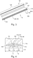
- Figure 5 shows an excerpt from Figure 1 marked with the mark D, along an in Figure 1 Section curve CC shown through the cable harness system 15.
- the cable harness system 15 is curved and follows a curvature of the inside 35 in the motor vehicle 10.
- the first profile 150 is also essentially constant in the curved second section 185 .
- the second wall section 155 has, in the second section 185, a variable third profile 186 that repeats itself again in the longitudinal direction.
- the third profile 186 is designed such that an inner height between the second inner surface 180 and an outer surface 190, which is arranged on a side of the actuator 75 facing away from the cable harness 60, varies over the length of the body 130.
- the outer surface 190 is jagged in the sectional view C-C.
- the outer surface 190 can also be designed differently.
- the jagged third profile 186 extends over an entire transverse extent of the second wall section 155.
- an outer surface 190 of the body 130 which is arranged, for example, on an inner side 35 facing away from the outer surface 190 facing away, is (completely) covered by the casing 110.
- the casing 110 can also be arranged relative to the outer surface 190 in such a way that the outer surface 190 is exposed and is not covered by the casing 110.
- the second wall section 155 is designed to be softer or more elastic than the first wall section 145 in the longitudinal direction.
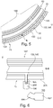
- Figure 6 shows one with a mark E in Figure 1 further excerpt from the in Figure 1 wiring harness system 15 shown along the in Figure 2 shown section plane BB.
- connection valve 195 can have a connection valve 195.
- the connection valve 195 is fluidically connected to the pressure chamber 135 on the inside.
- the connection valve 195 has a connection section 200 for connection, for example a pressure hose 196.
- the connection section 200 protrudes over a side surface 205 of the wiring harness system 15 out to the side.
- the connection valve 195 can also be arranged in such a way that the connection section 200 protrudes on the upper side or the lower side over an upper side or the lower side of the cable harness system 15.
- the connection valve 195 has a blocking position, wherein in the blocking position the connection valve 195 fluidically seals the pressure chamber 135 from the surroundings 105.
- connection valve 195 can also have an open position, the pressure chamber 135 being fluidically connected to the connection section 200 in the open position.
- the pressure fluid 140 can be discharged from the pressure chamber 135 or the pressure fluid 140 can be introduced into the pressure chamber 130 via the connection section 200, for example from a pressure reservoir 197 via the pressure hose 196.
- FIG. 13 shows a side view of that in FIG Figures 1 to 6 shown wiring harness system 15 in a transport position.
- connection valve 195 is arranged, for example, adjacent to the second contact device 70, while, on the other hand, the first contact device 65 is arranged on the inside quasi in the center of the spiral-shaped arrangement of the cable assembly system 15.
- the connection valve 195 is arranged on the outside of the cable harness system 15 and is therefore freely accessible both in the transport position and in the assembly position.
- the cable harness system 15 in the transport position can also be different from that in FIG Figure 7 take the form shown.
- the cable harness system 15 can also be shaped like a pretzel or half an eight.
- FIG. 13 shows a flow chart of a method for operating the in FIG Figures 1 to 7 wiring harness system 15 shown.
- the cable harness system 15 is produced.
- the electrical cables 90 and the actuator 75 are mounted together, for example.
- the actuator 75 and the cable harness 60 are mounted on a molding board.
- the actuator 75 is connected to the cable harness 60 by means of the sheath 110 in the assembly position.
- the casing 110 can be produced by injecting the foam material, the foam material flowing around and embedding both the cable harness 60 and the actuator 75.
- the foam material foams up to form the casing 110 and hardens. It is particularly advantageous here if the foam material for forming the casing 110 has a greater elasticity than the actuator 75.
- the pressure fluid in the pressure chamber 135 is not pressurized, so that the actuator 75 is slackened in the assembly position, for example.
- the cable harness system 15 can be removed from the molding space of the molding board.
- the sheathing 110 is in the form of banding
- the cable harness system 15 can be removed from the molding board.
- a second method step 305 which follows the first method step, the actuator 75 is moved from the assembly position into the transport position. This is done with the Figures 1 to 7 shown wiring harness system 15 to the effect that the connection valve 195 is connected to the pressure hose 196 and the pressure fluid 140 is introduced into the pressure chamber 135 via the connection valve 195.
- the pressurized pressurized fluid 140 acts on the elongated body 130 to deform the elongated body 130 under the pressure of the pressurized fluid. Due to the different elasticity of the body 130, in particular as a result of the different profiles 150, 160, 185, the pressure causes it to move from the assembly position to the transport position. As in Figure 7 It is shown that the actuator 75 spirals into the cable harness 60 and / or, for example, that the actuator 75 curves in the second section 185 and stretches in a straight line in the first section 126. By connecting the actuator 75 to the cable harness 60, the actuator 75 actuates the cable harness 60, so that the cable harness 60 is also in the transport position at the end of the deformation of the actuator 75.
- a shape of the cable construction system 15 both in the assembly position and / or in the transport position can also be predefined in connection with the cable harness 60.
- a rigidity of the electrical conductor 95 of the individual electrical cables 90 and / or of the cable sheathing 95 can be taken into account in the design of the cable harness system.
- the cable harness system 15 is designed to be more rigid on one side in the longitudinal direction than on the side on which the actuator 75 is arranged. If the pressure fluid 140 is introduced into the pressure chamber 135, the actuator 75 expands, so that the cable harness system 15 curves through the rigid cable harness 60 and is arranged in a spiral shape in the transport position.
- connection valve 195 prevents the pressurized fluid 140 from flowing out of the pressure chamber 135.
- the cable harness system 15 is packaged in the transport position and brought from its manufacturing location, for example by means of a truck or a transport vehicle, to the installation location.
- the pressure of the pressure fluid 140 in the pressure chamber 130 is essentially maintained by the fluid-tight pressure chamber 135, so that the cable harness system 15 can be transported particularly easily, for example packaged in cardboard boxes.
- a fourth method step 315 following the third method step 310 the packaged cable harness system 15 is unpacked at the assembly site and, in the unpacked state, is positioned at a predefined position with a predefined orientation relative to the component on the component 20.
- At least one of the fastening means 85 can be used to fasten the cable harness system 15 with the component 20 for fixation.
- a fifth method step 320 following the fourth method step 315 the pressure fluid 140 is let out of the pressure chamber 135 via the connection valve 195.
- the actuator 75 moves from the transport position to the assembly position.
- the rigidity of both the jacket 110 and the wire harness 60 can assist the actuator 75 in moving to the assembly position from the transport position to move.
- the cable harness system 15 sets itself down independently, that is to say without additional support, for example from a fitter or other automated assembly aids, for example a robot, along the predefined path 81 in the assembly area 80.
- the sections 126, 185 ensure that the actuator 75 deposits the cable harness 60 along the path 81 in the assembly position.
- a sixth method step 325 following the fifth method step 320 the cable harness system 15 is finally completely fastened to the component 20 by means of the (further) fastening means 85.
- the actuator 75 remains on the cable harness 60 and is not dismantled.
- the motor vehicle 10 is further assembled; for example, in the seventh method step 330, the interior trim 40 is attached to the component 20 so that the cable harness system 15 is not accessible without further dismantling.
- the cable harness system 15 can also be designed such that the pressure chamber 135 of the actuator 75 is filled with the pressure fluid 140 to maintain the mounting position and the pressure fluid 140 acts on the body 130 in such a way that the body 130 maintains the mounting position. If the pressure fluid 140 is withdrawn from the pressure chamber 135 via the connection valve 195, the actuator 75 moves from the assembly position to the transport position. In this embodiment, in order to unfold the cable harness system 15 after transport, the pressure fluid 140 is introduced into the pressure chamber 135 in the fifth method step 320, so that the actuator 75 moves from the transport position to the assembly position and thereby takes the cable harness 60 and the sheathing 110 with it.
- This alternative embodiment of the method for operating the cable harness system 15 as well as the configuration of the cable harness 60 has the advantage that the cable harness system 15 is particularly rigid in the assembly position due to the pressure-filled actuator 75 and therefore the actuator 75 is particularly effective both in the first method step 300 can be connected to the cable harness 60 and in the sixth method step 325, in particular, the unfolded cable harness system 15 can be fastened to the component 20 by means of the fastening elements 85.
- the pressure fluid 140 can be discharged from the pressure space 135.
- the fixation with the fastening means 85 is avoids the actuator 75 being able to return to the transport position after the pressure fluid 140 has been released from the pressure chamber 135.
- Figure 9 shows a schematic representation of the motor vehicle 10 with a cable harness system 15 according to a second embodiment.
- the wiring harness system 15 is essentially identical to that in FIGS Figures 1 to 7 shown wiring harness system 15 formed according to the first embodiment. In the following, the differences between the in Figure 9 shown wiring harness system 15 compared to that in the Figures 1 to 7 showed wiring harness system 15 received.
- the actuator 75 of the in Figure 9 Although the wiring harness system 15 shown has the soft-robotic structure 125, the soft-robotic structure 125 in FIG Figure 9 electrically operated.
- the actuator 75 can have a dielectric elastomer 210, an electrical connection 215 and a third contact device 220.
- the third contact device 220 is arranged, for example, at the position at which in the Figures 1 to 7 the connection valve 195 is arranged so that the third contact device 220 is accessible from the outside both in the assembly position and in the transport position.
- the electrical connection 215 electrically connects the third contact device 220 to the dielectric elastomer 210.
- the dielectric elastomer 210 is strip-like and thin-walled and is arranged to run essentially parallel to the cable harness 60.
- the dielectric elastomer 210 is arranged to run parallel to the cable harness 60.
- the dielectric elastomer 210 is connected to the cable harness 60 through the jacket 110.
- the dielectric elastomer 210, the electrical connection 215 and, for example, at least a part of the third contact device 220 can be embedded at least in sections in the casing 110.
- the electrical connection 215 can be designed, for example, as a further electrical cable, and that the dielectric elastomer 210 is protected from mechanical damage. Furthermore, the dielectric elastomer 210 is electrically insulated from the surroundings 105 by the casing 110.
- FIG. 13 shows a sectional view along a line in FIG Figure 9 Section plane CC shown through the in Figure 9 shown wiring harness system 15.
- the dielectric elastomer 210 extends essentially over at least 80% of the maximum transverse extent b of the cable harness system 15 and is arranged parallel to the underside 127.
- the cable harness system 15 has an exemplary rectangular configuration.
- the dielectric elastomer 210 has a first electrode 225, a layer 230 and a second electrode 235.
- the second electrode 235 is arranged directly adjoining the layer 230 on a side of the layer 230 facing away from the cable harness 60.
- the first electrode 225 is arranged on the layer 230 on a side of the layer 230 facing the cable harness 60.
- the layer 230 is plate-shaped and extends in the transverse direction over at least 80% of the maximum extent of the cable harness system 15.
- the first electrode 225 and the second electrode 235 are made thinner in the height direction than the layer 230.
- the first electrode 225 and the second electrode 235 are designed to be electrically conductive and are electrically isolated from one another by the electrically insulating layer 230.
- the layer 230 has an elastic material, for example silicone or an acrylic material.
- FIG. 11 shows a detail of a sectional view along a FIG Figure 10 Section plane DD shown through the in Figure 11 shown wiring harness system 15.
- the actuator 75 can have a plurality of actuator sections 240, the actuator sections 240 being arranged at a distance from one another in the longitudinal direction.
- the first electrode 225 can be connected in series to one another by means of a first electrical connection 245 and the second electrode 235 by means of a second electrical connection 250.
- the individual actuator sections 240 can be of the same length or of different lengths in the longitudinal direction.
- the actuator 75 can also be designed without interruption, so that the actuator 75 has only one actuator section 240.
- FIG. 13 shows a flow chart of a method for operating the in FIG Figures 9 to 11 wiring harness system 15 shown.
- the third contact device 200 in the assembly of the cable harness system 15 is connected in the first method step 300 to an electrical energy source 221, which provides a high voltage.
- the voltage provided by the electrical energy source is at least 2,000 to 10,000 volts.
- the applied voltage between the two electrodes 225, 235 forms an electric field between the two electrodes 225, 235, which acts on the electrodes 225, 235 and causes the first electrode 225 and the second electrode 235 to repel one another .
- Due to the elastic and electrically insulating configuration of the layer 230, the height direction of the actuator 75 extends and maintains the assembly position while maintaining the electrical energy supply.
- the actuator 75 is connected together with the cable harness 60 through the sheathing 110 in the first method step.
- the electrical energy supply is disconnected from the third contact device 220 in the fourth method step 315, so that the electrical energy supply for the actuator 75 is interrupted.
- the separation of the electrical energy source 221 from the actuator 75 has the effect that the electrical field between the first electrode 225 and the second electrode 235 collapses and there are no longer any repulsive forces between the two electrodes 225, 235.
- the (relieved) elastic layer 230 contracts, so that the actuator 75 is thinner in the height direction than in the assembly position. This has the effect that the actuator 75 changes from the assembly position to the transport position.
- the actuator 75 takes the cable harness 60 with it, so that the cable harness 60 with the actuator 75 is in the compact transport position for transport in the fifth method step 320.
- the contraction of layer 230 causes wiring harness system 15 to curve into the shape shown in FIG Figure 7 Transport position shown by the existing cable harness 60, which prevents the cable harness system 15 from being able to contract on the side on which the cable harness 60 is arranged.
- the actuator 75 is again connected to a (further) electrical energy source 221 via the third contact device 220.
- the electrical energy source 221 provides electrical energy for transferring the actuator 75 ready from the transport position to the assembly position.
- the actuator 75 takes the cable harness 60 and the sheath 110 with it when moving from the transport position to the assembly position. If the cable harness system 15 has assumed the assembly position, it is fastened to the component 20 by means of the fastening means 85. The actuator 75 is then disconnected from the electrical energy source 211. However, a movement of the actuator 75 back into its transport position is prevented by the fastening means 85 and the cable harness system 15 is held in the assembly position.
- the in Figure 12 described method could also be modified so that in the assembly position the actuator 75 is separated from the electrical energy source 221 and to transfer the actuator 75 from the assembly position to the transport position and back electrical energy is to be provided for the actuator 75 and during the transport the electrical energy Energy source 221 is connected to the actuator 75 and the electrical energy supply is maintained.
- the electrical energy source 221 can be carried in a transport box.
- the cable harness system 15 after the cable harness system 15 has been transferred by the actuator 75 from the assembly position to the transport position, the cable harness system 15 is fixed and packaged in the transport position and remains in the transport position even without maintaining the electrical energy supply.
- This has the advantage that after the cable harness system 15 has been positioned in the fourth method step 315 after the fixing of the cable harness system 15 in the transport position has been removed, the cable harness system 15 automatically moves into and assumes the assembly position.
- the actuator 75 could be connected to the electrical energy source 221 and then the fixation of the cable harness system 15 could be removed.
- the cable harness system 15 can be easily positioned on the component 20 and fixed to the component 20 with at least one fastening means 85.
- the electrical energy source 221 can be separated from the actuator 75, so that the actuator 75 moves from the transport position to the assembly position and takes the cable harness 20 and the sheathing 110 with it.
- the cable harness system 15 described above and the methods described above have the advantage that the cable harness system 15 is automatically attached to the component 20 laid along the predefined path 81. As a result, the cable harness system 15 can be assembled in a fully automated assembly process without a fitter manually laying out and positioning the cable harness system 15 on the component 20 - as is currently the case.
- the actuator 75 has a kink protection function, so that it is avoided that individual electrical cables 90 of the cable harness 60, in particular for transport below a minimal bending radius, are bent and damaged in the process. In this way, possible transport damage caused by the cable harness system 15 described above can be prevented.
Landscapes
- Engineering & Computer Science (AREA)
- Mechanical Engineering (AREA)
- Installation Of Indoor Wiring (AREA)
Abstract
Die Erfindung betrifft ein Kabelbaumsystem und ein Verfahren zum Betrieb eines Kabelbaumsystems, wobei das Kabelbaumsystem wenigstens einen Aktuator und wenigstens einen Kabelbaum mit wenigstens einem elektrischen Kabel aufweist, wobei der Aktuator mit dem Kabelbaum verbunden ist, wobei der Aktuator ausgebildet ist, den Kabelbaum zwischen einer Transportposition und einer zur Transportposition unterschiedlichen Montageposition zu bewegen.The invention relates to a cable harness system and a method for operating a cable harness system, the cable harness system having at least one actuator and at least one cable harness with at least one electrical cable, the actuator being connected to the cable harness, the actuator being designed to move the cable harness between a transport position and to move to an assembly position different from the transport position.
Description
Diese Patentanmeldung beansprucht die Priorität der deutschen Patentanmeldung
Die Erfindung betrifft ein Kabelbaumsystem gemäß Patentanspruch 1 und ein Verfahren zum Betrieb eines solchen Kabelbaumsystems gemäß Patentanspruch 11.The invention relates to a cable harness system according to claim 1 and a method for operating such a cable harness system according to claim 11.
Es ist ein Kabelbaum mit mehreren Kabeln bekannt, wobei an dem jeweiligen Ende des Kabelbaums eine Kontakteinrichtung angeordnet ist. Der Kabelbaum wird auf einem Formbrett hergestellt und nach Herstellung vom Formbrett abgenommen, manuell zusammengelegt und verpackt. Zur Montage im Kraftfahrzeug wird nach Entpacken des Kabelbaums der Kabelbaum wieder manuell im Fahrzeug verlegt. Die manuellen Arbeitsschritte sind zeitlich aufwendig und kostenintensiv.A cable harness with a plurality of cables is known, a contact device being arranged at the respective end of the cable harness. The wiring harness is produced on a molding board and after production is removed from the molding board, manually folded and packaged. For assembly in the motor vehicle, after unpacking the cable harness, the cable harness is laid manually in the vehicle again. The manual work steps are time-consuming and costly.
Es ist Aufgabe der Erfindung ein verbessertes Kabelbaumsystem und ein verbessertes Verfahren zum Betrieb solch eines Kabelbaumsystems bereitzustellen.It is the object of the invention to provide an improved cable harness system and an improved method for operating such a cable harness system.
Diese Aufgabe wird mittels eines Kabelbaumsystems gemäß Patentanspruch 1 und eines Verfahrens zum Betrieb solch eines Kabelbaumsystems gemäß Patentanspruch 11 gelöst. Vorteilhafte Ausführungsformen sind in den abhängigen Ansprüchen angegeben.This object is achieved by means of a cable harness system according to claim 1 and a method for operating such a cable harness system according to claim 11. Advantageous embodiments are specified in the dependent claims.
Es wurde erkannt, dass ein verbessertes Kabelbaumsystem für ein Kraftfahrzeug dadurch bereitgestellt werden kann, dass der Kabelbaum einen Aktuator und einen Kabelbaum mit wenigstens einem elektrischen Kabel aufweist. Der Aktuator ist mit dem Kabelbaum verbunden. Der Aktuator ist ausgebildet, den Kabelbaum zwischen einer Transportposition und einer zur Transportposition unterschiedlichen Montageposition zu bewegen.It has been recognized that an improved cable harness system for a motor vehicle can be provided in that the cable harness has an actuator and a cable harness with at least one electrical cable. The actuator is connected to the wiring harness. The actuator is designed to move the cable harness between a transport position and an assembly position different from the transport position.
Diese Ausgestaltung hat den Vorteil, dass der Kabelbaum durch den Aktuator automatisiert sich ein- und ausfalten kann, ohne dass hierfür der Kabelbaum manuell zu bewegen ist.This embodiment has the advantage that the cable harness can automatically fold in and out by the actuator without the cable harness having to be moved manually for this purpose.
In einer weiteren Ausführungsform ist der Aktuator ausgebildet, in der Transportposition und/oder in der Montageposition den Kabelbaum zu halten. Dadurch kann auf zusätzliche Verpackungsmittel oder auf ein Formbrett verzichtet werden.In a further embodiment, the actuator is designed to hold the cable harness in the transport position and / or in the assembly position. This means that there is no need for additional packaging or a molding board.
In einer weiteren Ausführungsform ist in der Transportposition der Kabelbaum eingefaltet und/oder eingerollt. In der Montageposition ist der Kabelbaum entlang einer vordefinierten Bahn ausgelegt. Dabei weist der Kabelbaum eine größere Erstreckung auf als in der Transportposition.In a further embodiment, the cable harness is folded in and / or rolled up in the transport position. In the assembly position, the cable harness is laid out along a predefined path. The cable harness has a greater extension than in the transport position.
In einer weiteren Ausführungsform weist das Kabelbaumsystem eine Ummantelung auf, wobei die Ummantelung zumindest abschnittsweise den Kabelbaum umgreift und den Kabelbaum mit dem Aktuator verbindet. Der Aktuator ist vorzugsweise zumindest abschnittsweise in die Ummantelung eingebettet. Diese Ausgestaltung hat den Vorteil, dass das Kabelbaumsystem besonders kompakt ausgebildet ist. Zweckmäßig ist hierbei, wenn die Ummantelung einen Schaumwerkstoff aufweist.In a further embodiment, the cable harness system has a sheathing, the sheathing at least partially encompassing the cable harness and connecting the cable harness to the actuator. The actuator is preferably embedded in the casing at least in sections. This configuration has the advantage that the cable harness system is designed to be particularly compact. It is useful here if the casing has a foam material.
In einer weiteren Ausführungsform weist der Aktuator eine Soft-Robotic-Struktur auf. Dadurch kann das Kabelbaumsystem besonders leicht ausgebildet sein. Ferner ist das Kabelbaumsystem durch die Soft-Robotic-Struktur sehr flexibel und kann auch bei manuellem Verlegen, beispielsweise bei einer Reparatur des Kraftfahrzeugs, ohne weitere Beschädigung wieder von einer Komponente, beispielsweise einem Karosserieelement des Kraftfahrzeugs entfernt und danach wieder an dieser Komponente montiert werden.In a further embodiment, the actuator has a soft robotic structure. As a result, the cable harness system can be designed to be particularly light. Furthermore, the cable harness system is very flexible due to the soft-robotic structure and can also be removed from a component, for example a body element of the motor vehicle, without further damage, even if it is manually laid, for example when the motor vehicle is being repaired, and then reassembled on this component.
In einer weiteren Ausführungsform weist der Aktuator einen elastischen langgestreckten Körper auf, wobei der Körper innenseitig einen gegenüber der Umgebung des Kabelbaums fluiddichten Druckraum begrenzt, wobei der Druckraum mit einem Druckfluid füllbar ist, wobei das Druckfluid druckbeaufschlagbar oder druckentlastbar ist, wobei das Druckfluid auf den flexiblen Körper einen druckbeaufschlagenden oder druckentlastenden Druck ausübt, der bewirkt, dass sich mindestens ein Teil des elastisch länglichen Körpers krümmt und/oder streckt. Diese Ausgestaltung hat den Vorteil, dass das Kabelbaumsystem, insbesondere der Aktuator und die Ummantelung aus einem besonders kostengünstigen und elastischen Material gefertigt werden können. Ferner kann beispielsweise als Druckfluid Druckluft verwendet werden, die an üblichen Montageplätzen in der Fertigung eines Kraftfahrzeugs und/oder des Kabelbaums zur Verfügung steht.In a further embodiment, the actuator has an elastic elongated body, the body delimiting on the inside a pressure chamber which is fluid-tight with respect to the surroundings of the cable harness, the pressure chamber being fillable with a pressure fluid, the pressure fluid being pressurizable or relieved of pressure, the pressure fluid being applied to the flexible Body exerts a pressurizing or pressure relieving pressure, which causes at least a part of the elastically elongated body to bend and / or stretch. This configuration has the advantage that the cable harness system, in particular the actuator and the sheathing, can be manufactured from a particularly inexpensive and elastic material. Furthermore, compressed air can be used as the pressure fluid, for example, which is available at customary assembly locations in the manufacture of a motor vehicle and / or the cable harness.
In einer weiteren Ausführungsform ist der Druckraum an einer Seite des Kabelbaums angeordnet und verläuft im Wesentlichen parallel zum Kabelbaum. Dabei erstreckt sich der Druckraum vorzugsweise zu wenigstens 90 %, insbesondere im Wesentlichen über eine gesamte Längserstreckung des Kabelbaums.In a further embodiment, the pressure chamber is arranged on one side of the cable harness and runs essentially parallel to the cable harness. The Pressure chamber preferably to at least 90%, in particular essentially over the entire length of the cable harness.
In einer weiteren Ausführungsform weist der langgestreckte Körper einen ersten Wandabschnitt mit einem Profil und einem gegenüberliegend zum Wandabschnitt angeordneten zweiten Wandabschnitt auf. Der erste Wandabschnitt ist auf einer dem Kabelbaum zugewandten Seite und der zweite Wandabschnitt ist auf einer dem Kabelbaum abgewandten Seite angeordnet. Der zweite Wandabschnitt weist ein sich wiederholendes, variables weiteres Profil auf, wobei das weitere Profil derart ausgebildet ist, dass eine innere Höhe des zweiten Wandabschnitts über eine Länge variiert. Zusätzlich oder alternativ kann der zweite Wandabschnitt eine höhere Elastizität aufweisen als der erste Wandabschnitt. Der zweite Wandabschnitt ist ausgebildet, den Aktuator zusammen mit dem Kabelbaum als Reaktion auf eine Änderung des Druckfluids zu krümmen.In a further embodiment, the elongated body has a first wall section with a profile and a second wall section arranged opposite to the wall section. The first wall section is arranged on a side facing the cable harness and the second wall section is arranged on a side facing away from the cable harness. The second wall section has a repetitive, variable further profile, the further profile being designed in such a way that an inner height of the second wall section varies over a length. Additionally or alternatively, the second wall section can have a higher elasticity than the first wall section. The second wall portion is configured to bend the actuator together with the wire harness in response to a change in the pressurized fluid.
In einer weiteren Ausführungsform weist das Kabelbaumsystem ein Anschlussventil auf. Das Anschlussventil ist fluidisch mit dem Druckraum verbunden. Das Anschlussventil ist derart angeordnet, dass das Anschlussventil sowohl in der Transportposition als auch in der Montageposition von außen zugänglich ist.In a further embodiment, the cable harness system has a connection valve. The connection valve is fluidically connected to the pressure chamber. The connection valve is arranged in such a way that the connection valve is accessible from the outside both in the transport position and in the assembly position.
In einer weiteren Ausführungsform weist der Aktuator ein dielektrisches Elastomer, eine elektrische Verbindung und eine Kontakteinrichtung auf, wobei das dielektrische Elastomer mit dem Kabelbaum mechanisch verbunden ist. Die elektrische Verbindung verbindet das dielektrische Elastomer mit der Kontakteinrichtung elektrisch. Die Kontakteinrichtung ist (zur Bereitstellung einer elektrischen Energie) mit einer elektrischen Energiequelle elektrisch verbindbar.In a further embodiment, the actuator has a dielectric elastomer, an electrical connection and a contact device, the dielectric elastomer being mechanically connected to the cable harness. The electrical connection electrically connects the dielectric elastomer to the contact device. The contact device can be electrically connected to an electrical energy source (for providing electrical energy).
In einer weiteren Ausführungsform ist das dielektrische Elastomer bandartig und dünnwandig ausgebildet und im Wesentlichen parallel verlaufend zum Kabelbaum angeordnet. Dadurch ist das Kabelbaumsystem besonders dünnwandig ausbildbar.In a further embodiment, the dielectric elastomer is designed in the manner of a strip with thin walls and is arranged to run essentially parallel to the cable harness. As a result, the cable harness system can be designed with particularly thin walls.
Im Betrieb des oben beschriebenen Kabelbaumsystems wird zum Transport des Kabelbaumsystems bewegt der Aktuator den Kabelbaum aus der Montageposition in die Transportposition. Das Kabelbaumsystem wird an einer Komponente eines Kraftfahrzeugs, insbesondere an einem Karosserieelement des Kraftfahrzeugs, positioniert und in eine vordefinierte Ausrichtung relativ zur Komponente gebracht. Der Aktuator bewegt den Kabelbaum von der Transportposition in die Montageposition und legt den Kabelbaum entlang einer vordefinierten Bahn an der Komponente aus. Das Kabelbaumsystem wird in der Montageposition an der Komponente mittels wenigstens eines Befestigungsmittels befestigt.In the operation of the cable harness system described above, the actuator moves the cable harness from the assembly position into the transport position in order to transport the cable harness system. The cable harness system is positioned on a component of a motor vehicle, in particular on a body element of the motor vehicle, and brought into a predefined orientation relative to the component. The actuator moves the cable harness from the transport position to the assembly position and lays the cable harness out on the component along a predefined path. The wiring harness system is in the Mounting position attached to the component by means of at least one fastening means.
Diese Ausgestaltung hat den Vorteil, dass nicht manuell das Kabelbaumsystem an der Komponente ausgelegt und positioniert werden muss, sondern dies selbsttätig durch den im Kabelbaumsystem eingebauten Aktuator erfolgt.This refinement has the advantage that the cable harness system does not have to be laid out and positioned manually on the component, but this is done automatically by the actuator built into the cable harness system.
Besonders zweckmäßig ist, wenn zur Überführung des Kabelbaums von der Transportposition in die Montageposition oder von der Montageposition in die Transportposition ein druckbeaufschlagendes Druckfluid in den Druckraum eingeleitet wird, wobei das Druckfluid auf den flexiblen Körper einen druckbeaufschlagenden Druck ausübt, wobei der Druck bewirkt, dass sich mittels eines Teils des elastisch länglichen Körpers der Aktuator sich krümmt oder sich streckt. Der Aktuator nimmt den Kabelbaum mit.It is particularly useful if a pressurized pressure fluid is introduced into the pressure chamber to transfer the cable harness from the transport position to the assembly position or from the assembly position to the transport position, the pressure fluid exerting a pressurizing pressure on the flexible body, the pressure causing by means of part of the elastically elongated body, the actuator curves or stretches. The actuator takes the wiring harness with it.
Zweckmäßig kann auch sein, dass zur Überführung des Kabelbaums von der Transportposition in die Montageposition oder von der Montageposition in die Transportposition das Druckfluid aus dem Druckraum ausgeleitet wird, wobei ein Umgebungsdruck auf den flexiblen Körper einen druckbeaufschlagenden Druck ausübt, wobei der Druck bewirkt, dass mindestens ein Teil des elastisch länglichen Körpers des Aktuators sich krümmt oder sich streckt. Der Aktuator nimmt den Kabelbaum mit.It can also be expedient for the pressure fluid to be discharged from the pressure chamber in order to transfer the cable harness from the transport position to the assembly position or from the assembly position to the transport position, an ambient pressure exerting a pressurizing pressure on the flexible body, the pressure causing at least a part of the elastically elongated body of the actuator curves or stretches. The actuator takes the wiring harness with it.
In einer weiteren Ausführungsform wird eine elektrische Energiequelle bereitgestellt, wobei die elektrische Energiequelle mit der Kontakteinrichtung elektrisch verbunden ist, wobei die elektrische Energiequelle eine elektrische Energie dem Aktuator bereitstellt, wobei mittels der elektrischen Energie der Aktuator von der Montageposition in die Transportposition oder von der Transportposition in die Montageposition bewegt wird, wobei die elektrische Energie in der Montageposition oder in der Transportposition vorzugsweise fortwährend bereitgestellt wird, wobei der Aktuator den Kabelbaum mitnimmt und den Kabelbaum von der Transportposition in die Montageposition oder von der Montageposition in die Transportposition überführt.In a further embodiment, an electrical energy source is provided, the electrical energy source being electrically connected to the contact device, the electrical energy source providing electrical energy to the actuator, the actuator being moved from the assembly position to the transport position or from the transport position in the assembly position is moved, wherein the electrical energy is preferably continuously provided in the assembly position or in the transport position, the actuator taking the cable harness with it and transferring the cable harness from the transport position to the assembly position or from the assembly position to the transport position.
Nachfolgend wird die Erfindung anhand von Figuren näher erläutert. Dabei zeigen:
- Figur 1
- eine perspektivische Darstellung eines Ausschnitts eines Kraftfahrzeugs;
- Figur 2
- eine Schnittansicht durch ein Kabelbaumsystem des Kraftfahrzeugs entlang einer in
Figur 1 gezeigten Schnittebene A-A durch das inFigur 1 gezeigte Kabelbaumsystem; - Figur 3
- einen Ausschnitt einer Schnittansicht entlang einer in
Figur 2 gezeigten Schnittebene B-B durch das inFigur 2 gezeigte Kabelbaumsystem; - Figur 4
- einen Ausschnitt einer Schnittansicht entlang der in Figur gezeigten Schnittebene A-A durch das Kabelbaumsystem;
- Figur 5
- einen Ausschnitt, der in
Figur 1 mit der Markierung D markiert ist, entlang der inFigur 2 gezeigten Schnittebene B-B durch das Kabelbaumsystem; - Figur 6
- einen mit einer Markierung E in
Figur 1 gezeigten weiteren Ausschnitt des inFigur 1 gezeigten Kabelbaumsystems entlang der inFigur 2 gezeigten Schnittebene B-B; - Figur 7
- eine Seitenansicht auf das in den
Figuren 1 bis 6 gezeigte Kabelbaumsystem in einer Transportposition; - Figur 8
- ein Ablaufdiagramm eines Verfahrens zum Betrieb des in den
Figuren 1 bis 7 gezeigten Kabelbaumsystems; - Figur 9
- eine schematische Darstellung des Kraftfahrzeugs mit einem Kabelbaumsystem gemäß einer zweiten Ausführungsform;
Figur 10- eine Schnittansicht entlang einer in
Figur 9 gezeigten Schnittebene C-C durch das inFigur 9 gezeigte Kabelbaumsystem; - Figur 11
- einen Ausschnitt einer Schnittansicht entlang einer in
Figur 10Figur 11 gezeigte Kabelbaumsystem; und - Figur 12
- ein Ablaufdiagramm eines Verfahrens zum Betrieb des in den
Figuren 9 bis 11 gezeigten Kabelbaumsystems.
- Figure 1
- a perspective view of a section of a motor vehicle;
- Figure 2
- a sectional view through a wiring harness system of the motor vehicle along an in
Figure 1 Section plane AA shown through the inFigure 1 wiring harness system shown; - Figure 3
- a detail of a sectional view along an in
Figure 2 Section plane BB shown through the inFigure 2 wiring harness system shown; - Figure 4
- a detail of a sectional view along the sectional plane AA shown in Figure through the cable harness system;
- Figure 5
- a section that appears in
Figure 1 marked with the mark D, along the inFigure 2 Section plane BB shown through the cable harness system; - Figure 6
- one with a mark E in
Figure 1 further excerpt from the inFigure 1 wiring harness system shown along the inFigure 2 section plane BB shown; - Figure 7
- a side view of the in the
Figures 1 to 6 Cable harness system shown in a transport position; - Figure 8
- a flowchart of a method for operating the in FIG
Figures 1 to 7 wiring harness system shown; - Figure 9
- a schematic representation of the motor vehicle with a cable harness system according to a second embodiment;
- Figure 10
- a sectional view along an in
Figure 9 Section plane CC shown through the inFigure 9 wiring harness system shown; - Figure 11
- a detail of a sectional view along an in
Figure 10 Section plane DD shown through the inFigure 11 wiring harness system shown; and - Figure 12
- a flowchart of a method for operating the in FIG
Figures 9 to 11 harness system shown.
Das Kraftfahrzeug 10 weist ein Kabelbaumsystem 15 und wenigstens eine Komponente 20 auf, vorzugsweise ein Karosserieelement 25. Das Karosserieelement 25 ist in der Ausführungsform beispielhaft als Fahrzeugtüre ausgebildet. Auch kann die Komponente 20 des Kraftfahrzeugs 10 andersartig als in
Die Komponente 20 weist eine Befestigungsfläche 30 auf. Die Befestigungsfläche 30 ist in dem Ausführungsbeispiel eine Innenseite 35 des Karosserieelements 25. Die Innenseite 35 begrenzt zusammen mit einer Türinnenverkleidung (in
Die Komponente 20 kann beispielhaft mehrere Strukturelemente 50, insbesondere Versteifungselemente, aufweisen, wobei das Versteifungselement 50 beispielsweise aus einem Blech ausgeformt sein kann. Das Versteifungselement 50 dient dazu, die Komponente 20 zu versteifen, sodass die Komponente 20 vordefinierte Bedingungen an eine Steifigkeit, beispielsweise für einen Seitenaufprallschutz und/oder an eine Verwindungssteifigkeit, einhält.The component 20 can, for example, have a plurality of
Das Kraftfahrzeug 10 kann beispielsweise eine weitere Komponente 55 aufweisen, wobei die weitere Komponente 55 beispielsweise ein Steuergerät oder ein Antriebsmotor, beispielsweise zum Antrieb eines Fensterelements des Kraftfahrzeugs 10, ist. In der Ausführungsform ist beispielhaft im Innenraum 45 zwischen der Innenverkleidung 40 und der Befestigungsfläche 30 die weitere Komponente 55 angeordnet.The
Das Kabelbaumsystem 15 weist einen Kabelbaum 60, beispielhaft eine erste Kontakteinrichtung 65, eine zweite Kontakteinrichtung 70 und einen Aktuator 75 auf. Der Aktuator 75 ist in
Der Aktuator 75 ist mittels der Ummantelung 110 mit dem Kabelbaum 60 mechanisch verbunden. Der Aktuator 75 erstreckt sich über wenigstens 80 %, vorzugsweise 90 %, insbesondere 95 %, einer Längserstreckung des Kabelbaums 60. Dabei ist ein erstes Längsende 115 des Aktuators 75 im Wesentlichen angrenzend zur ersten Kontakteinrichtung 65 und ein zweites Längsende 120 im Wesentlichen angrenzend an die zweite Kontakteinrichtung 70 angeordnet (vgl.
Der Kabelbaum 60 verbindet elektrisch die erste Kontakteinrichtung 65 mit der zweiten Kontakteinrichtung 70. In
Die erste Kontakteinrichtung 65 kann mit einer weiteren nicht dargestellten Kontakteinrichtung eines weiteren Kabelbaumsystems (in
In
Der Montagebereich 80 schließt sich innenseitig an die Befestigungsfläche 30 an und wird geometrisch beispielhaft durch die Strukturelemente 50 der Komponente 20 seitlich begrenzt. Der Montagebereich 80 ist dabei der Bereich, in dem der Kabelbaum 60 zusammen mit dem Aktuator 75 verläuft und in dem der Kabelbaum 60 zu führen ist, um den Kabelbaum 60 zusammen mit dem Aktuator 75 mittels wenigstens eines Befestigungsmittels 85, beispielsweise mittels eines Halteclips oder einer zu verschraubenden oder verklippenden Halteschelle, mit der Komponente 20 formschlüssig zu verbinden. Selbstverständlich ist auch denkbar, dass das Befestigungsmittel 85 den Kabelbaum 60 zusammen mit dem Aktuator 75 stoffschlüssig, beispielsweise mittels einer Klebverbindung in dem Montagebereich 80 an der Komponente 20, beispielsweise an der Befestigungsfläche 30, befestigt. Selbstverständlich kann das Kabelbaumsystem 15 auch lose in dem Montagebereich 80 verlegt sein.The mounting
Der Kabelbaum 60 weist ein oder mehrere elektrische Kabel 90 auf, wobei jedes der elektrischen Kabel 90 einen elektrischen Leiter 95 und eine Leiterummantelung 100 aufweist. Die elektrischen Leiter 95 des Kabelbaums 60 verlaufen im Wesentlichen parallel zueinander, wobei eine Haupterstreckungsrichtung des elektrischen Leiters 95 im Wesentlichen eine Längsrichtung des Kabelbaums 60 definiert.The
In Querrichtung senkrecht zu der Längsrichtung sind die elektrischen Kabel 90 des Kabelbaums 60 beabstandet zueinander oder in direktem Kontakt zueinander angeordnet. Die elektrischen Kabel 90 können im Wesentlichen identisch zueinander aber auch unterschiedlich zueinander ausgebildet sein. Die Leiterummantelung 100 ummantelt umfangsseitig den elektrischen Leiter 95 und isoliert den elektrischen Leiter 95 gegenüber den anderen elektrischen Kabeln und/oder einer Umgebung 105 des Kabelbaumsystems 15.In the transverse direction perpendicular to the longitudinal direction, the
Das Kabelbaumsystem 15 weist ferner eine Ummantelung 110 auf. Die Ummantelung 110 ummantelt die einzelnen elektrischen Kabel 90 und verbindet die elektrischen Kabel 90 miteinander. Die Ummantelung 110 kann beispielsweise einen Schaumwerkstoff aufweisen, wobei das elektrische Kabel 90, vorzugsweise alle elektrischen Kabel 90 des Kabelbaums 60 in der Ummantelung 110 eingebettet sind. In einer alternativen Ausführungsform ist die Ummantelung 110 als Bandierung ausgebildet, wobei die Bandierung umfangsseitig um die elektrischen Kabel 90 gewickelt ist und die elektrischen Kabel 90 aneinander drückt.The
Der Kabelbaum 60 ist in der Ausführungsform ausschließlich zur Verbindung der ersten Kontakteinrichtung 65 mit der zweiten Kontakteinrichtung 70 ausgebildet und weist keine weitere Verästelung auf. Selbstverständlich ist auch denkbar, dass der Kabelbaum 60 verästelt, beispielsweise Y-artig und/oder mit mehreren Abzweigungen versehen, ausgebildet ist. Auch kann der Kabelbaum 60 nur ein elektrisches Kabel 90 und/oder einen elektrischen Leiter 95 aufweisen, der die erste Kontakteinrichtung 65 mit der zweiten Kontakteinrichtung 70 elektrisch verbindet.In the embodiment, the
Das Kabelbaumsystem 15 weist neben dem Kabelbaum 60 den parallel zum Kabelbaum 60 verlaufenden Aktuator 75 auf. Der Aktuator 75 ist an einer Seite, in
Die Ummantelung 110 umgreift den Kabelbaum 60, insbesondere die einzelnen elektrischen Kabel 90 umfangsseitig und verbindet die elektrischen Kabel 90 miteinander und mit dem Aktuator 75. Insbesondere wird durch eine Einbettung in einen Schaumwerkstoff der Ummantelung 110 eine zuverlässige Verbindung zwischen dem Aktuator 75 und dem Kabelbaum 60 sowie den einzelnen elektrischen Kabeln 90 untereinander sichergestellt.The
Alternativ zu der Einbettung des Aktuators 75 in die Ummantelung 110 ist auch denkbar, dass unterseitig an die Ummantelung 110 der Aktuator 75 mit der Ummantelung 110 verbunden, beispielsweise stoffschlüssig verbunden, ist. Auch kann die Ummantelung 110 als Bandierung ausgeführt sein, die um den Aktuator 75 und den Kabelbaum 60 gewickelt ist.As an alternative to embedding the
Der Aktuator 75 ist im Wesentlichen parallel verlaufend zu dem Kabelbaum 60 angeordnet. Der Aktuator 75 weist eine Soft-Robotic-Struktur 125 auf.The
Die Soft-Robotic-Struktur 125 weist in
Der Aktuator 75 weist einen ersten Abschnitt 126 auf. Im ersten Abschnitt 126 ist der langgestreckte Körper 130 geradlinig verlaufend ausgebildet.The
Im ersten Abschnitt 126 weist der Körper 130 einen ersten Wandabschnitt 145 mit einem ersten Profil 150 und einen gegenüberliegend zum ersten Wandabschnitt 145 angeordneten zweiten Wandabschnitt 155 mit einem zweiten Profil 160 auf. Der erste Wandabschnitt 145 ist auf einer zum Kabelbaum 60 zugewandten Seite und der zweite Wandabschnitt 155 auf einer zum Kabelbaum 60 abgewandten Seite angeordnet.In the
In
In Höhenrichtung weist jeweils der erste Wandabschnitt 145 und der zweite Wandabschnitt 155 im Wesentlichen die gleiche Dicke auf. Die Dicke ist deutlich geringer als eine Maximalerstreckung des Kabelbaumsystems 15 in Höhenrichtung.In the vertical direction, the
Das zweite Profil 160 kann spiegelsymmetrisch zu einer Symmetrieebene, die parallel zur Unterseite verläuft und in der das erste und zweite Querende 165, 170 angeordnet sind, zu dem ersten Wandabschnitt 145 ausgebildet sein. Dabei kann das zweite Profil 160 rechteckförmig oder konkav ausgebildet sein. Zusammen bilden der erste Wandabschnitt 145 und der zweite Wandabschnitt 155 eine schlauchartige Ausgestaltung des Aktuators 75 aus.The
Der erste Wandabschnitt 145 weist eine erste Innenfläche 175 und der zweite Wandabschnitt 155 weist eine zweite Innenfläche 180 auf. In der Ausführungsform können, wie in
Der Aktuator 75 weist in der Ausführungsform wenigstens einen der folgenden Werkstoffe auf: Kautschuk, Silikon, Polyethylen, Polyamid, Polyvinylchlorid, Thermoplast, Weichkunststoff. Vorzugsweise ist der Werkstoff flexibel und vorzugsweise im Wesentlichen nicht oder nur geringfügig (kleiner 5 Prozent, insbesondere kleiner 2 Prozent) mit dem druckbeaufschlagten Druckfluid 140 dehnbar. Ferner ist der Werkstoff im Wesentlichen vorzugweise fluiddicht, insbesondere gegenüber dem Druckfluid 140. So kann beispielsweise der Werkstoff luftdicht und/oder flüssigkeitsdicht sein.In the embodiment, the
In einem zweiten Abschnitt 185, der sich an den ersten Abschnitt 126 in Längsrichtung anschließt, ist das Kabelbaumsystem 15 gekrümmt ausgebildet und folgt einer Krümmung der Innenseite 35 in dem Kraftfahrzeug 10. Auch im gekrümmten zweiten Abschnitt 185 ist das erste Profil 150 im Wesentlichen konstant ausgebildet.In a second section 185, which adjoins the
Der zweite Wandabschnitt 155 weist im zweiten Abschnitt 185 ein variables, sich wieder in Längsrichtung wiederholendes drittes Profil 186 auf. Das dritte Profil 186 ist derart ausgebildet, dass eine innere Höhe zwischen der zweiten Innenfläche 180 und einer Außenfläche 190, die auf einer dem Kabelbaum 60 abgewandten Seite des Aktuators 75 angeordnet ist, über die Länge des Körpers 130 variiert. In der Ausführungsform ist die Außenfläche 190 zackenartig in der Schnittansicht C-C ausgebildet. Selbstverständlich kann die Außenfläche 190 auch andersartig ausgebildet sein. Das zackenartige dritte Profil 186 erstreckt sich über eine gesamte Quererstreckung des zweiten Wandabschnitts 155.The
Durch die Einbettung des Körpers 130 in die Ummantelung 110 ist eine Außenfläche 190 des Körpers 130, die auf einer zur abgewandten Außenfläche 190 abgewandten Innenseite 35 beispielhaft angeordnet ist, durch die Ummantelung 110 (vollständig) bedeckt. Auch kann die Ummantelung 110 zu der Außenfläche 190 so angeordnet sein, dass die Außenfläche 190 freiliegt und nicht durch die Ummantelung 110 bedeckt ist.By embedding the
Durch das dritte Profil 186 ist in Längsrichtung der zweite Wandabschnitt 155 weicher beziehungsweise elastischer ausgebildet als der erste Wandabschnitt 145.As a result of the
Zusätzlich kann das Kabelbaumsystem 15 ein Anschlussventil 195 aufweisen. Das Anschlussventil 195 ist innenseitig mit dem Druckraum 135 fluidisch verbunden. Das Anschlussventil 195 weist einen Anschlussabschnitt 200 zum Anschluss, beispielsweise eines Druckschlauchs 196, auf. Der Anschlussabschnitt 200 ragt über eine Seitenfläche 205 des Kabelbaumsystems 15 seitlich heraus. Auch kann das Anschlussventil 195 derartig angeordnet sein, dass der Anschlussabschnitt 200 oberseitig oder unterseitig über eine Oberseite oder die Unterseite des Kabelbaumsystems 15 herausragt. Das Anschlussventil 195 weist eine Sperrstellung auf, wobei in der Sperrstellung das Anschlussventil 195 den Druckraum 135 gegenüber der Umgebung 105 fluidisch abdichtet.In addition, the
Das Anschlussventil 195 kann ferner zusätzlich zu der Sperrstellung eine Durchlassstellung aufweisen, wobei in der Durchlassstellung der Druckraum 135 fluidisch mit dem Anschlussabschnitt 200 verbunden ist. In der Durchlassstellung kann beispielsweise das Druckfluid 140 aus dem Druckraum 135 ausgeleitet werden oder über den Anschlussabschnitt 200 beispielsweise aus einem Druckreservoir 197 über den Druckschlauch 196 das Druckfluid 140 in den Druckraum 130 eingeleitet werden.In addition to the blocking position, the
In der Transportposition ist das Kabelbaumsystem 15 beispielhaft spiralförmig eingewickelt und weist daher eine geringere Erstreckung auf als in der Montageposition. Dabei ist das Anschlussventil 195 beispielhaft benachbart zu der zweiten Kontakteinrichtung 70 angeordnet, während hingegen die erste Kontakteinrichtung 65 innenseitig quasi im Zentrum der spiralförmigen Anordnung des Kabelbausystems 15 angeordnet ist. Das Anschlussventil 195 ist außenseitig am Kabelbaumsystem 15 angeordnet und daher sowohl in der Transportposition als auch in der Montageposition frei zugänglich.In the transport position, the
Selbstverständlich kann das Kabelbaumsystem 15 in der Transportposition auch eine andere als in
In einem ersten Verfahrensschritt 300 wird das Kabelbaumsystem 15 hergestellt. Dabei werden die elektrischen Kabel 90 und der Aktuator 75 beispielsweise gemeinsam montiert. Beispielsweise erfolgt die Montage des Aktuators 75 und des Kabelbaums 60 an einem Formbrett. Der Aktuator 75 wird mit dem Kabelbaum 60 mittels der Ummantelung 110 in der Montageposition verbunden. So kann beispielsweise nach dem Einlegen der elektrischen Kabel 90 für den Kabelbaum 60 und des Aktuator 75 in einem gemeinsamen Formraum des Formbretts, die Ummantelung 110 durch ein Einspritzen des Schaumwerkstoffs hergestellt werden, wobei der Schaumwerkstoff sowohl den Kabelbaum 60 als auch den Aktuator 75 umfließt und einbettet. Der Schaumwerkstoff schäumt zur Ummantelung 110 auf und härtet aus. Von besonderem Vorteil ist hierbei, wenn der Schaumwerkstoff zur Ausbildung der Ummantelung 110 eine größere Elastizität aufweist als der Aktuator 75.In a
Beispielhaft ist in der Montageposition das Druckfluid in dem Druckraum 135 nicht druckbeaufschlagt, sodass der Aktuator 75 in der Montageposition beispielhaft erschlafft ist. Dies hat den Vorteil, dass der Aktuator 75 besonders einfach zusammen mit dem Kabelbaum 60 an dem Formbrett, insbesondere in den Formraum, verlegt bzw. eingelegt werden kann.For example, in the assembly position, the pressure fluid in the pressure chamber 135 is not pressurized, so that the
Nach dem Aushärten des Schaumwerkstoffs kann beispielsweise das Kabelbaumsystem 15 aus dem Formraum des Formbretts entnommen werden.After the foam material has cured, for example the
Wird beispielsweise die Ummantelung 110 als Bandierung ausgebildet, kann nach Umwickelung des Aktuators 75 zusammen mit dem Kabelbaum 60 das Kabelbaumsystem 15 vom Formbrett entfernt werden.If, for example, the
In einem zweiten Verfahrensschritt 305, der auf den ersten Verfahrensschritt folgt, wird der Aktuator 75 von der Montageposition in die Transportposition verfahren. Dies erfolgt bei dem in den
Das druckbeaufschlagte Druckfluid 140 wirkt auf den langgestreckten Körper 130 dahingehend, dass der langgestreckte Körper 130 sich unter dem Druck des Druckfluids verformt. Der Druck bewirkt, durch die unterschiedliche Elastizität des Körpers 130, insbesondere resultierend aus den unterschiedlichen Profilen 150, 160, 185 von der Montageposition sich in die Transportposition bewegt. Dabei kann, wie in
Eine Form des Kabelbausystem 15 sowohl in der Montageposition und/oder in der Transportposition kann auch in Verbindung mit dem Kabelbaum 60 vordefiniert festgelegt sein. Insbesondere kann in der Auslegung des Kabelbaumsystem hierbei eine Steifigkeit des elektrischen Leiters 95 der einzelnen elektrischen Kabel 90 und/oder der Kabelummantelung 95 mit berücksichtigt werden.A shape of the
So ist beispielsweise einseitig das Kabelbaumsystem 15 in Längsrichtung steifer ausgebildet als an der Seite, an der der Aktuator 75 angeordnet ist. Wird das Druckfluid 140 in den Druckraum 135 eingeleitet, so dehnt sich der Aktuator 75 aus, sodass durch den steifen Kabelbaum 60 sich das Kabelbaumsystem 15 krümmt und in der Transportposition spiralförmig angeordnet ist.For example, the
Nachdem das Druckfluid 140 auf einen vordefinierten Druck gebracht worden ist, wird kein weiteres Druckfluid 140 in den Druckraum 135 eingeleitet und beispielsweise der Druckschlauch 196 vom Anschlussventil 195 abgezogen. Das Anschlussventil 195 verhindert durch Verbleiben in der Sperrstellung, dass das Druckfluid 140 aus dem Druckraum 135 ausströmt.After the pressure fluid 140 has been brought to a predefined pressure, no further pressure fluid 140 is introduced into the pressure chamber 135 and, for example, the
In einem dritten Verfahrensschritt 310 wird das Kabelbaumsystem 15 in der Transportposition verpackt und von seinem Herstellungsort, beispielsweise mittels Lkw oder einem Transportwagen, zum Einbauort verbracht. Durch den fluiddichten Druckraum 135 wird der Druck des Druckfluids 140 im Druckraum 130 im Wesentlichen aufrechterhalten, sodass das Kabelbaumsystem 15 besonders einfach, beispielsweise in Kartons verpackt, transportiert werden kann.In a
In einem auf den dritten Verfahrensschritt 310 folgenden vierten Verfahrensschritt 315 wird das verpackte Kabelbaumsystem 15 am Montageort entpackt und in entpacktem Zustand an eine vordefinierte Position mit einer vordefinierten Ausrichtung relativ zu der Komponente an der Komponente 20 positioniert. Dabei kann bereits mit zumindest einem der Befestigungmittel 85 das Kabelbaumsystem 15 mit der Komponente 20 zur Fixierung befestigt werden.In a
In einem auf den vierten Verfahrensschritt 315 folgenden fünften Verfahrensschritt 320 wird das Druckfluid 140 über das Anschlussventil 195 aus dem Druckraum 135 ausgelassen. Dadurch verfährt sich der Aktuator 75 von der Transportposition in die Montageposition. Die Steifigkeit sowohl der Ummantelung 110 als auch des Kabelbaums 60 kann den Aktuator 75 dabei unterstützen, um in die Montageposition von der Transportposition sich zu bewegen. Dabei legt sich in der Montageposition das Kabelbaumsystem 15 eigenständig, das heißt ohne zusätzliche Unterstützung beispielsweise eines Monteurs oder weiterer automatisierter Montagehilfseinrichtungen, beispielsweise eines Roboters, entlang der vordefinierten Bahn 81 im Montagebereich 80 ab. Die Abschnitte 126, 185 stellen sich, dass der Aktuator 75 den Kabelbaum 60 entlang der Bahn 81 in der Montageposition ablegt.In a
In einem auf den fünften Verfahrensschritt 320 folgenden sechsten Verfahrensschritt 325 wird mittels des (weiteren) Befestigungsmittels 85 das Kabelbaumsystem 15 an der Komponente 20 abschließend vollständig befestigt. Der Aktuator 75 verbleibt dabei weiterhin an dem Kabelbaum 60 und wird nicht demontiert.In a
In einem fakultativen siebten Verfahrensschritt 330 wird das Kraftfahrzeug 10 weiter montiert, beispielsweise wird im siebten Verfahrensschritt 330 die Innenverkleidung 40 an der Komponente 20 befestigt, sodass das Kabelbaumsystem 15 nicht ohne weitere Demontage zugänglich ist.In an optional
Selbstverständlich kann das Kabelbaumsystem 15 auch derartig ausgebildet sein, dass zur Aufrechterhaltung der Montageposition der Druckraum 135 des Aktuators 75 mit dem Druckfluid 140 befüllt ist und das Druckfluid 140 auf den Körper 130 derartig wirkt, dass der Körper 130 die Montageposition aufrechterhält. Wird das Druckfluid 140 über das Anschlussventil 195 aus dem Druckraum 135 entnommen, so bewegt sich der Aktuator 75 von der Montageposition in die Transportposition. Um das Kabelbaumsystem 15 nach dem Transport zu entfalten, wird in dieser Ausgestaltung im fünften Verfahrensschritt 320 das Druckfluid 140 in den Druckraum 135 eingeleitet, sodass der Aktuator 75 sich von der Transportposition in die Montageposition bewegt und dabei den Kabelbaum 60 und die Ummantelung 110 mitnimmt.Of course, the
Diese alternative Ausgestaltung des Verfahrens zum Betrieb des Kabelbaumsystems 15 als auch die Ausgestaltung des Kabelbaums 60 hat den Vorteil, dass das Kabelbaumsystem 15 durch den druckbefüllten Aktuator 75 in der Montageposition besonders steif ausgebildet ist und dadurch besonders gut sowohl im ersten Verfahrensschritt 300 der Aktuator 75 mit dem Kabelbaum 60 verbunden werden kann als auch im sechsten Verfahrensschritt 325 besonders das entfaltete Kabelbaumsystem 15 mittels der Befestigungselemente 85 an der Komponente 20 befestigt werden kann. In der alternativen Ausführungsform kann nach Montage des Befestigungmittels 85 das Druckfluid 140 aus dem Druckraum 135 ausgelassen werden. Durch die Fixierung mit dem Befestigungsmittel 85 wird vermieden, dass nach Auslassen des Druckfluids 140 aus dem Druckraum 135 der Aktuator 75 wieder in die Transportposition zurückkehren kann.This alternative embodiment of the method for operating the
Das Kabelbaumsystem 15 ist im Wesentlichen identisch zu dem in den
Der Aktuator 75 des in
Die elektrische Verbindung 215 verbindet elektrisch die dritte Kontakteinrichtung 220 mit dem dielektrischen Elastomer 210. Das dielektrische Elastomer 210 ist bandartig und dünnwandig ausgebildet und ist im Wesentlichen parallel verlaufend zu dem Kabelbaum 60 angeordnet. Das dielektrische Elastomer 210 ist parallel zu dem Kabelbaum 60 verlaufend angeordnet. Durch die Ummantelung 110 ist das dielektrische Elastomer 210 mit dem Kabelbaum 60 verbunden. Ebenso können das dielektrische Elastomer 210, die elektrische Verbindung 215 und beispielsweise zumindest ein Teil der dritten Kontakteinrichtung 220 in der Ummantelung 110 zumindest abschnittsweise eingebettet sein. Dies hat den Vorteil, dass die die elektrische Verbindung 215 beispielsweise als weiteres elektrisches Kabel ausgebildet sein kann, und dass das dielektrische Elastomer 210 vor einer mechanischen Beschädigung geschützt ist. Ferner ist das dielektrische Elastomer 210 gegenüber der Umgebung 105 elektrisch durch die Ummantelung 110 isoliert.The electrical connection 215 electrically connects the third contact device 220 to the
Das dielektrische Elastomer 210 erstreckt sich im Wesentlichen über wenigstens 80 % der maximalen Quererstreckung b des Kabelbaumsystems 15 und ist parallel zu der Unterseite 127 angeordnet. Das Kabelbaumsystem 15 eine beispielhaft rechteckförmige Ausgestaltung auf.The
Das dielektrische Elastomer 210 weist eine erste Elektrode 225, eine Schicht 230 und eine zweite Elektrode 235 auf. Die zweite Elektrode 235 ist direkt angrenzend an die Schicht 230 auf einer zum Kabelbaum 60 abgewandten Seite der Schicht 230 angeordnet. Die erste Elektrode 225 ist auf der Schicht 230 auf einer dem Kabelbaum 60 zugewandten Seite der Schicht 230 angeordnet.The
Die Schicht 230 ist plattenförmig ausgebildet und erstreckt sich in Querrichtung über wenigstens 80 % der Maximalerstreckung des Kabelbaumsystems 15. Die erste Elektrode 225 und die zweite Elektrode 235 sind in Höhenrichtung dünner ausgebildet als die Schicht 230.The
Die erste Elektrode 225 und die zweite Elektrode 235 sind elektrisch leitend ausgebildet und werden durch die elektrisch isolierende Schicht 230 elektrisch voneinander isoliert. Die Schicht 230 weist einen elastischen Werkstoff, beispielsweise Silikon oder einen Acrylwerkstoff auf.The
Der Aktuator 75 kann mehrere Aktuatorabschnitte 240 aufweisen, wobei die Aktuatorabschnitte 240 in Längsrichtung beabstandet zueinander angeordnet sind. Dabei kann jeweils die erste Elektrode 225 mittels einer ersten elektrischen Verbindung 245 und die zweite Elektrode 235 mittels einer zweiten elektrischen Verbindung 250 jeweils untereinander in Serie geschalten sein. Die einzelnen Aktuatorabschnitte 240 können gleich lang oder in Längsrichtung unterschiedlich lang ausgebildet sein. Auch kann der Aktuator 75 unterbrechungsfrei ausgebildet sein, sodass der Aktuator 75 nur einen Aktuatorabschnitt 240 aufweist.The
Das Verfahren ist im Wesentlichen identisch zu dem in
Um den Aktuator 75 zwischen der Montageposition und der Transportposition zu bewegen, wird in der Ausführungsform die dritte Kontakteinrichtung 200 in der Montage des Kabelbaumsystems 15 im ersten Verfahrensschritt 300 mit einer elektrischen Energiequelle 221, die eine Hochspannung bereitgestellt, verbunden. Die von der elektrischen Energiequelle bereitgestellte Spannung beträgt wenigstens 2.000 bis 10.000 Volt. Durch die anliegende Spannung zwischen den beiden Elektroden 225, 235 bildet sich ein elektrisches Feld zwischen den beiden Elektroden 225, 235 aus, das auf die Elektroden 225, 235 wirkt und dazu führt, dass die erste Elektrode 225 und die zweiten Elektrode 235 sich gegenseitig abstoßen. Durch die elastische und elektrisch isolierende Ausgestaltung der Schicht 230 streckt sich Höhenrichtung der Aktuator 75 und hält bei Aufrechterhaltung der elektrischen Energieversorgung die Montageposition aufrecht. In der Montageposition wird der Aktuator 75 im ersten Verfahrensschritt zusammen mit dem Kabelbaum 60 durch die Ummantelung 110 verbunden.In order to move the
Zum Transport wird im vierten Verfahrensschritt 315 die elektrische Energieversorgung von der dritten Kontakteinrichtung 220 abgetrennt, sodass die elektrische Energieversorgung für den Aktuator 75 unterbrochen wird. Das Trennen der elektrischen Energiequelle 221 von dem Aktuator 75 bewirkt, dass das elektrische Feld zwischen der ersten Elektrode 225 und der zweiten Elektrode 235 zusammenbricht und keine Abstoßungskräfte mehr zwischen den beiden Elektroden 225, 235 vorliegen. Dadurch zieht sich die (entlastete) elastische Schicht 230 zusammen, sodass in Höhenrichtung der Aktuator 75 dünner ist als in der Montageposition. Dies bewirkt, dass der Aktuator 75 von der Montageposition in die Transportposition übergeht. Dabei nimmt der Aktuator 75 den Kabelbaum 60 mit, sodass mit dem Aktuator 75 der Kabelbaum 60 zum Transport im fünften Verfahrensschritt 320 sich in der kompakten Transportposition befindet. Beispielhaft bewirkt das Zusammenziehen der Schicht 230 ein Krümmen des Kabelbaumsystems 15 in die in
Zur Montage im sechsten Verfahrensschritt 325 wird wieder über die dritte Kontakteinrichtung 220 der Aktuator 75 mit einer (weiteren) elektrischen Energiequelle 221 verbunden. Die elektrische Energiequelle 221 stellt elektrische Energie zur Überführung des Aktuators 75 aus der Transportposition in die Montageposition bereit. Der Aktuator 75 nimmt den Kabelbaum 60 und die Ummantelung 110 bei der Bewegung von der Transportposition in die Montageposition mit. Hat das Kabelbaumsystem 15 die Montageposition eingenommen, so wird es mittels des Befestigungsmittels 85 an der Komponente 20 befestigt. Im Anschluss daran wird der Aktuator 75 von der elektrischen Energiequelle 211 getrennt. Eine Bewegung des Aktuators 75 dann wieder zurück in seine Transportposition wird jedoch durch das Befestigungsmittel 85 verhindert und das Kabelbaumsystem 15 wird in der Montageposition gehalten.For assembly in the
Es wird darauf hingewiesen, dass das in
Alternativ ist auch denkbar, dass nach Überführung des Kabelbaumsystems 15 durch den Aktuator 75 von der Montageposition in die Transportposition das Kabelbaumsystem 15 in der Transportposition fixiert und verpackt wird und auch ohne Aufrechterhaltung der elektrischen Energieversorgung in der Transportposition verbleibt. Dies hat den Vorteil, dass nach Positionierung des Kabelbaumsystems 15 im vierten Verfahrensschritt 315 nach Entfernung der Fixierung des Kabelbaumsystems 15 in der Transportposition das Kabelbaumsystem 15 sich selbsttägig in die Montageposition bewegt und diese einnimmt.Alternatively, it is also conceivable that after the
Zusätzlich könnte auch vor Entfernen der Fixierung in der Transportposition der Aktuator 75 mit der elektrischen Energiequelle 221 verbunden werden und im Anschluss daran die Fixierung des Kabelbaumsystems 15 entfernt werden. Dadurch kann das Kabelbaumsystem 15 einfach an der Komponente 20 positioniert werden und mit zumindest einem Befestigungsmittel 85 an der Komponente 20 fixiert werden. Nach Fixierung kann die elektrische Energiequelle 221 von dem Aktuator 75 getrennt werden, sodass der Aktuator 75 sich von der Transportposition in die Montageposition bewegt und den Kabelbaum 20 und die Ummantelung 110 mitnimmt.In addition, before removing the fixation in the transport position, the
Das oben beschriebene Kabelbaumsystem 15 und die oben beschriebenen Verfahren haben den Vorteil, dass das Kabelbaumsystem 15 sich selbsttätig an der Komponente 20 entlang der vordefinierten Bahn 81 verlegt. Dadurch kann das Kabelbaumsystem 15 in einem vollautomatisierten Montageprozess montiert werden ohne dass hierbei - wie derzeit - manuell ein Monteur das Kabelbaumsystem 15 an der Komponente 20 auslegt und positioniert.The
Ferner wird vermieden, dass durch das selbsttätige Einnehmen der Transportposition ein Verheddern des Kabelbaumsystems 15, insbesondere bei einer komplizierten Ausgestaltung des Kabelbaumsystems 15 mit einer zahlreichen Verästelung des Kabelbaums 60 entsteht. Des Weiteren hat der Aktuator 75 eine Knickschutzfunktion, sodass vermieden wird, dass einzelne elektrische Kabel 90 des Kabelbaums 60, insbesondere zum Transport unterhalb eines minimalen Biegeradius, verbogen werden und dabei beschädigt werden. Dadurch können mögliche Transportschäden durch das oben beschriebene Kabelbaumsystem 15 verhindert werden.Furthermore, it is avoided that the automatic assumption of the transport position entangles the
- 1010
- KraftfahrzeugMotor vehicle
- 1515th
- KabelbaumsystemWiring harness system
- 2020th
- Komponentecomponent
- 2525th
- KarosserieelementBody element
- 3030th
- BefestigungsflächeMounting surface
- 3535
- Innenseiteinside
- 4040
- TürinnenverkleidungInner door trim
- 4545
- Innenrauminner space
- 5050
- StrukturelementStructural element
- 5555
- weitere Komponentefurther component
- 6060
- KabelbaumWiring harness
- 6565
- erste Kontakteinrichtungfirst contact device
- 7070
- zweite Kontakteinrichtungsecond contact device
- 7575
- AktuatorActuator
- 8080
- MontagebereichAssembly area
- 8181
- Bahntrain
- 8585
- BefestigungsmittelFasteners
- 9090
- elektrisches Kabelelectrical cable
- 9595
- elektrischer Leiterelectrical conductor
- 100100
- LeiterummantelungConductor sheathing
- 105105
- Umgebungvicinity
- 110110
- UmmantelungSheathing
- 115115
- erste Längsendefirst longitudinal end
- 120120
- zweites Längsendesecond longitudinal end
- 125125
- Soft-Robotic-StrukturSoft robotic structure
- 126126
- erster Abschnittfirst section
- 127127
- Unterseitebottom
- 130130
- (langgestreckter) Körper(elongated) body
- 135135
- DruckraumPrinting room
- 140140
- DruckfluidPressure fluid
- 145145
- erster Wandabschnittfirst wall section
- 150150
- erstes Profilfirst profile
- 155155
- zweiter Wandabschnittsecond wall section
- 160160
- zweites Profilsecond profile
- 165165
- erstes Querendefirst transverse end
- 170170
- zweites Querendesecond transverse end
- 175175
- erste Innenflächefirst inner surface
- 180180
- zweite Innenflächesecond inner surface
- 185185
- zweiter Abschnittsecond part
- 186186
- drittes Profilthird profile
- 190190
- AußenflächeExterior surface
- 195195
- AnschlussventilConnection valve
- 196196
- Druckschlauchpressure hose
- 197197
- DruckreservoirPressure reservoir
- 200200
- AnschlussabschnittConnection section
- 205205
- SeitenflächeSide face
- 210210
- dielektrisches Elastomerdielectric elastomer
- 215215
- elektrische Verbindungelectrical connection
- 220220
- dritte Kontakteinrichtungthird contact device
- 221221
- elektrische Energiequelleelectrical energy source
- 225225
- erste Elektrodefirst electrode
- 230230
- Schichtlayer
- 235235
- zweite Elektrodesecond electrode
- 240240
- AktuatorabschnittActuator section
- 245245
- erste elektrische Verbindungfirst electrical connection
- 250250
- zweite elektrische Verbindungsecond electrical connection
- 300300
- erster Verfahrensschrittfirst procedural step
- 305305
- zweiter Verfahrensschrittsecond procedural step
- 310310
- dritter Verfahrensschrittthird process step
- 315315
- vierter Verfahrensschrittfourth procedural step
- 320320
- fünfter Verfahrensschrittfifth procedural step
- 325325
- sechster Verfahrensschrittsixth procedural step
- 330330
- siebter Verfahrensschrittseventh procedural step
Claims (14)
Applications Claiming Priority (1)
| Application Number | Priority Date | Filing Date | Title |
|---|---|---|---|
| DE102020100859.7A DE102020100859A1 (en) | 2020-01-15 | 2020-01-15 | Self-deploying cable harness system with a cable harness and with an actuator and a method for operating such a cable harness system |
Publications (1)
| Publication Number | Publication Date |
|---|---|
| EP3851331A1 true EP3851331A1 (en) | 2021-07-21 |
Family
ID=74187122
Family Applications (1)
| Application Number | Title | Priority Date | Filing Date |
|---|---|---|---|
| EP21151872.5A Pending EP3851331A1 (en) | 2020-01-15 | 2021-01-15 | Self-deploying cable harness system with a cable harness and with an actuator and method for operating such a cable harness system |
Country Status (2)
| Country | Link |
|---|---|
| EP (1) | EP3851331A1 (en) |
| DE (1) | DE102020100859A1 (en) |
Cited By (1)
| Publication number | Priority date | Publication date | Assignee | Title |
|---|---|---|---|---|
| WO2023012326A1 (en) * | 2021-08-06 | 2023-02-09 | Yazaki Systems Technologies Gmbh | Cable harness and arrangement with such a cable harness |
Families Citing this family (1)
| Publication number | Priority date | Publication date | Assignee | Title |
|---|---|---|---|---|
| DE102022115703A1 (en) * | 2022-06-23 | 2023-12-28 | Yazaki Systems Technologies Gmbh | Router clip, wire harness, form and method |
Citations (6)
| Publication number | Priority date | Publication date | Assignee | Title |
|---|---|---|---|---|
| EP0855312A2 (en) * | 1996-12-25 | 1998-07-29 | Sumitomo Wiring Systems, Ltd. | A wiring harness arranging construction |
| DE10328688A1 (en) * | 2003-06-26 | 2005-01-13 | Volkswagen Ag | Process for using wiring looms in road vehicles, using fitting that has bar code for identification of wires |
| US20050092512A1 (en) * | 2003-10-29 | 2005-05-05 | Yazaki Corporation | Continuous electric power supply device |
| US20120034816A1 (en) * | 2010-08-05 | 2012-02-09 | Toyota Motor Engineering & Manufacturing North America, Inc. | Vehicular retractable cable systems |
| DE112010005431T5 (en) * | 2010-03-30 | 2013-03-28 | Sumitomo Wiring Systems, Ltd. | Wiring harness and method of manufacturing the same |
| WO2013148340A2 (en) * | 2012-03-26 | 2013-10-03 | President And Fellows Of Harvard College | Systems and methods for providing flexible robotic actuators |
Family Cites Families (3)
| Publication number | Priority date | Publication date | Assignee | Title |
|---|---|---|---|---|
| DE465416C (en) * | 1925-03-28 | 1928-09-17 | Kabelfabrik Akt Ges | Process for the production of a multi-core electric line cord insulated with a common rubber jacket |
| US2299140A (en) * | 1939-06-28 | 1942-10-20 | Union Carbide & Carbon Corp | Wire harness |
| DE4026718C3 (en) * | 1990-08-24 | 2000-11-30 | Delphi Automotive Systems Gmbh | Wiring harness |
-
2020
- 2020-01-15 DE DE102020100859.7A patent/DE102020100859A1/en active Pending
-
2021
- 2021-01-15 EP EP21151872.5A patent/EP3851331A1/en active Pending
Patent Citations (6)
| Publication number | Priority date | Publication date | Assignee | Title |
|---|---|---|---|---|
| EP0855312A2 (en) * | 1996-12-25 | 1998-07-29 | Sumitomo Wiring Systems, Ltd. | A wiring harness arranging construction |
| DE10328688A1 (en) * | 2003-06-26 | 2005-01-13 | Volkswagen Ag | Process for using wiring looms in road vehicles, using fitting that has bar code for identification of wires |
| US20050092512A1 (en) * | 2003-10-29 | 2005-05-05 | Yazaki Corporation | Continuous electric power supply device |
| DE112010005431T5 (en) * | 2010-03-30 | 2013-03-28 | Sumitomo Wiring Systems, Ltd. | Wiring harness and method of manufacturing the same |
| US20120034816A1 (en) * | 2010-08-05 | 2012-02-09 | Toyota Motor Engineering & Manufacturing North America, Inc. | Vehicular retractable cable systems |
| WO2013148340A2 (en) * | 2012-03-26 | 2013-10-03 | President And Fellows Of Harvard College | Systems and methods for providing flexible robotic actuators |
Cited By (1)
| Publication number | Priority date | Publication date | Assignee | Title |
|---|---|---|---|---|
| WO2023012326A1 (en) * | 2021-08-06 | 2023-02-09 | Yazaki Systems Technologies Gmbh | Cable harness and arrangement with such a cable harness |
Also Published As
| Publication number | Publication date |
|---|---|
| DE102020100859A1 (en) | 2021-07-15 |
Similar Documents
| Publication | Publication Date | Title |
|---|---|---|
| EP3851331A1 (en) | Self-deploying cable harness system with a cable harness and with an actuator and method for operating such a cable harness system | |
| EP2337697B1 (en) | Glass seal | |
| DE3505214C2 (en) | Method of applying an elastic piece of tubing to one end of an elongated body | |
| DE102013210470A1 (en) | Drive transmission system and method for assembling such a drive transmission system | |
| DE102012203571C5 (en) | A method for plastically forming a plurality of electrically conductive layers of a flat conductor to a multi-dimensional contour and devices for this method | |
| DE102018104768A1 (en) | Actuator with back stiff chain | |
| EP2763256A2 (en) | Cable ducts with feed-through terminal, kit for a feed-through terminal and method for mounting a feed-through terminal for a cable duct | |
| DE202016106705U1 (en) | actuator | |
| DE69909684T2 (en) | Dense passage device of an electrical wiring harness through the passage opening of a vehicle bulkhead and assembly method of the electrical wiring harness | |
| EP2678178B1 (en) | Arrangement for sealing line interfaces in a motor vehicle | |
| EP3456591B1 (en) | Component system for fixing a trim part and motor vehicle | |
| DE102017125498B4 (en) | Aircraft fuselage and module for absorbing crash energy in a lower deck of an aircraft used to transport passengers | |
| DE112011101088T5 (en) | Cable management and hose attachment | |
| DE2042183A1 (en) | Flexible flow medium line | |
| EP0279344A2 (en) | Flexible hose | |
| EP3188919B1 (en) | Door sealing device, door sealing system, and door leaf for a rail vehicle | |
| EP2086780B1 (en) | Vehicle door having a sealing plane and having a sealing element whose ends overlap | |
| DE102020103474A1 (en) | Valve actuator and valve | |
| DE60019272T2 (en) | Device for fastening a bellows and method for its use | |
| DE102012221220A1 (en) | Device for fastening pressure line within hydraulic track at wall of floor panel for clutch or brake operation of motor vehicle, has connectors connected with one another at connecting edges of outer surfaces | |
| EP3181188B1 (en) | Extendable eclectrode | |
| DE102019101084A1 (en) | Method of making a wire harness and a wire harness made by the method | |
| EP1263269B1 (en) | Foil conductor, such as foil conductor cable or foil circuit board | |
| DE202017106094U1 (en) | Thermally pre-insulated pipe clamp | |
| EP3354501B1 (en) | Seal, in particular on doors, flaps or/and the windows of vehicle bodies |
Legal Events
| Date | Code | Title | Description |
|---|---|---|---|
| PUAI | Public reference made under article 153(3) epc to a published international application that has entered the european phase |
Free format text: ORIGINAL CODE: 0009012 |
|
| STAA | Information on the status of an ep patent application or granted ep patent |
Free format text: STATUS: THE APPLICATION HAS BEEN PUBLISHED |
|
| AK | Designated contracting states |
Kind code of ref document: A1 Designated state(s): AL AT BE BG CH CY CZ DE DK EE ES FI FR GB GR HR HU IE IS IT LI LT LU LV MC MK MT NL NO PL PT RO RS SE SI SK SM TR |
|
| STAA | Information on the status of an ep patent application or granted ep patent |
Free format text: STATUS: REQUEST FOR EXAMINATION WAS MADE |
|
| 17P | Request for examination filed |
Effective date: 20220121 |
|
| RBV | Designated contracting states (corrected) |
Designated state(s): AL AT BE BG CH CY CZ DE DK EE ES FI FR GB GR HR HU IE IS IT LI LT LU LV MC MK MT NL NO PL PT RO RS SE SI SK SM TR |