EP3845255B1 - Cardiac pumping assistance device - Google Patents
Cardiac pumping assistance device Download PDFInfo
- Publication number
- EP3845255B1 EP3845255B1 EP19855486.7A EP19855486A EP3845255B1 EP 3845255 B1 EP3845255 B1 EP 3845255B1 EP 19855486 A EP19855486 A EP 19855486A EP 3845255 B1 EP3845255 B1 EP 3845255B1
- Authority
- EP
- European Patent Office
- Prior art keywords
- diaphragm
- heart
- cardiac output
- compression
- support apparatus
- Prior art date
- Legal status (The legal status is an assumption and is not a legal conclusion. Google has not performed a legal analysis and makes no representation as to the accuracy of the status listed.)
- Active
Links
- 230000000747 cardiac effect Effects 0.000 title claims description 68
- 238000005086 pumping Methods 0.000 title claims description 28
- 210000002216 heart Anatomy 0.000 claims description 134
- 230000006835 compression Effects 0.000 claims description 79
- 238000007906 compression Methods 0.000 claims description 79
- 239000000463 material Substances 0.000 claims description 20
- 239000008280 blood Substances 0.000 claims description 16
- 210000004369 blood Anatomy 0.000 claims description 16
- 238000005259 measurement Methods 0.000 claims description 13
- 239000012530 fluid Substances 0.000 claims description 11
- 238000001514 detection method Methods 0.000 claims description 10
- 239000007789 gas Substances 0.000 claims description 8
- 210000004351 coronary vessel Anatomy 0.000 claims description 7
- 210000002837 heart atrium Anatomy 0.000 claims description 7
- 230000002093 peripheral effect Effects 0.000 claims description 7
- 201000010099 disease Diseases 0.000 claims description 6
- 208000037265 diseases, disorders, signs and symptoms Diseases 0.000 claims description 6
- 238000003384 imaging method Methods 0.000 claims description 4
- 239000012528 membrane Substances 0.000 claims description 4
- QVGXLLKOCUKJST-UHFFFAOYSA-N atomic oxygen Chemical compound [O] QVGXLLKOCUKJST-UHFFFAOYSA-N 0.000 claims description 3
- 239000001301 oxygen Substances 0.000 claims description 3
- 229910052760 oxygen Inorganic materials 0.000 claims description 3
- XLYOFNOQVPJJNP-UHFFFAOYSA-N water Substances O XLYOFNOQVPJJNP-UHFFFAOYSA-N 0.000 description 17
- 210000000038 chest Anatomy 0.000 description 15
- 210000005246 left atrium Anatomy 0.000 description 14
- 210000005245 right atrium Anatomy 0.000 description 14
- 210000005241 right ventricle Anatomy 0.000 description 10
- 210000005240 left ventricle Anatomy 0.000 description 9
- 230000017531 blood circulation Effects 0.000 description 7
- 238000002474 experimental method Methods 0.000 description 6
- 230000001965 increasing effect Effects 0.000 description 6
- 238000010586 diagram Methods 0.000 description 5
- 208000010125 myocardial infarction Diseases 0.000 description 5
- 230000015556 catabolic process Effects 0.000 description 4
- 238000006731 degradation reaction Methods 0.000 description 4
- 238000001356 surgical procedure Methods 0.000 description 4
- 210000000709 aorta Anatomy 0.000 description 3
- 238000013130 cardiovascular surgery Methods 0.000 description 3
- 210000004379 membrane Anatomy 0.000 description 3
- 238000000034 method Methods 0.000 description 3
- 210000003492 pulmonary vein Anatomy 0.000 description 3
- 241001465754 Metazoa Species 0.000 description 2
- 206010000891 acute myocardial infarction Diseases 0.000 description 2
- 230000002612 cardiopulmonary effect Effects 0.000 description 2
- 230000008602 contraction Effects 0.000 description 2
- 230000000694 effects Effects 0.000 description 2
- 239000002657 fibrous material Substances 0.000 description 2
- 208000019622 heart disease Diseases 0.000 description 2
- 239000002649 leather substitute Substances 0.000 description 2
- 239000007788 liquid Substances 0.000 description 2
- 230000033001 locomotion Effects 0.000 description 2
- 210000004165 myocardium Anatomy 0.000 description 2
- 229920002379 silicone rubber Polymers 0.000 description 2
- 239000004945 silicone rubber Substances 0.000 description 2
- 208000024891 symptom Diseases 0.000 description 2
- 238000002560 therapeutic procedure Methods 0.000 description 2
- 238000013519 translation Methods 0.000 description 2
- 206010008479 Chest Pain Diseases 0.000 description 1
- 208000010496 Heart Arrest Diseases 0.000 description 1
- 208000006148 High Cardiac Output Diseases 0.000 description 1
- 206010028851 Necrosis Diseases 0.000 description 1
- 208000031481 Pathologic Constriction Diseases 0.000 description 1
- 208000007536 Thrombosis Diseases 0.000 description 1
- 239000000853 adhesive Substances 0.000 description 1
- 230000001070 adhesive effect Effects 0.000 description 1
- 239000000560 biocompatible material Substances 0.000 description 1
- 230000000903 blocking effect Effects 0.000 description 1
- 210000004204 blood vessel Anatomy 0.000 description 1
- 239000003575 carbonaceous material Substances 0.000 description 1
- 229910010293 ceramic material Inorganic materials 0.000 description 1
- 238000007796 conventional method Methods 0.000 description 1
- 238000005516 engineering process Methods 0.000 description 1
- 239000004744 fabric Substances 0.000 description 1
- 239000001307 helium Substances 0.000 description 1
- 229910052734 helium Inorganic materials 0.000 description 1
- SWQJXJOGLNCZEY-UHFFFAOYSA-N helium atom Chemical compound [He] SWQJXJOGLNCZEY-UHFFFAOYSA-N 0.000 description 1
- 230000001939 inductive effect Effects 0.000 description 1
- 230000002452 interceptive effect Effects 0.000 description 1
- 208000028867 ischemia Diseases 0.000 description 1
- 239000010985 leather Substances 0.000 description 1
- 210000003141 lower extremity Anatomy 0.000 description 1
- 230000017074 necrotic cell death Effects 0.000 description 1
- 230000003287 optical effect Effects 0.000 description 1
- 210000003516 pericardium Anatomy 0.000 description 1
- 229920001296 polysiloxane Polymers 0.000 description 1
- 229920002635 polyurethane Polymers 0.000 description 1
- 239000004814 polyurethane Substances 0.000 description 1
- 230000036262 stenosis Effects 0.000 description 1
- 208000037804 stenosis Diseases 0.000 description 1
- 210000001562 sternum Anatomy 0.000 description 1
Images


Classifications
-
- A—HUMAN NECESSITIES
- A61—MEDICAL OR VETERINARY SCIENCE; HYGIENE
- A61M—DEVICES FOR INTRODUCING MEDIA INTO, OR ONTO, THE BODY; DEVICES FOR TRANSDUCING BODY MEDIA OR FOR TAKING MEDIA FROM THE BODY; DEVICES FOR PRODUCING OR ENDING SLEEP OR STUPOR
- A61M60/00—Blood pumps; Devices for mechanical circulatory actuation; Balloon pumps for circulatory assistance
- A61M60/10—Location thereof with respect to the patient's body
- A61M60/122—Implantable pumps or pumping devices, i.e. the blood being pumped inside the patient's body
- A61M60/165—Implantable pumps or pumping devices, i.e. the blood being pumped inside the patient's body implantable in, on, or around the heart
- A61M60/191—Implantable pumps or pumping devices, i.e. the blood being pumped inside the patient's body implantable in, on, or around the heart mechanically acting upon the outside of the patient's native heart, e.g. compressive structures placed around the heart
-
- A—HUMAN NECESSITIES
- A61—MEDICAL OR VETERINARY SCIENCE; HYGIENE
- A61M—DEVICES FOR INTRODUCING MEDIA INTO, OR ONTO, THE BODY; DEVICES FOR TRANSDUCING BODY MEDIA OR FOR TAKING MEDIA FROM THE BODY; DEVICES FOR PRODUCING OR ENDING SLEEP OR STUPOR
- A61M60/00—Blood pumps; Devices for mechanical circulatory actuation; Balloon pumps for circulatory assistance
- A61M60/20—Type thereof
- A61M60/289—Devices for mechanical circulatory actuation assisting the residual heart function by means mechanically acting upon the patient's native heart or blood vessel structure, e.g. direct cardiac compression [DCC] devices
-
- A—HUMAN NECESSITIES
- A61—MEDICAL OR VETERINARY SCIENCE; HYGIENE
- A61M—DEVICES FOR INTRODUCING MEDIA INTO, OR ONTO, THE BODY; DEVICES FOR TRANSDUCING BODY MEDIA OR FOR TAKING MEDIA FROM THE BODY; DEVICES FOR PRODUCING OR ENDING SLEEP OR STUPOR
- A61M60/00—Blood pumps; Devices for mechanical circulatory actuation; Balloon pumps for circulatory assistance
- A61M60/40—Details relating to driving
- A61M60/465—Details relating to driving for devices for mechanical circulatory actuation
- A61M60/468—Details relating to driving for devices for mechanical circulatory actuation the force acting on the actuation means being hydraulic or pneumatic
-
- A—HUMAN NECESSITIES
- A61—MEDICAL OR VETERINARY SCIENCE; HYGIENE
- A61M—DEVICES FOR INTRODUCING MEDIA INTO, OR ONTO, THE BODY; DEVICES FOR TRANSDUCING BODY MEDIA OR FOR TAKING MEDIA FROM THE BODY; DEVICES FOR PRODUCING OR ENDING SLEEP OR STUPOR
- A61M60/00—Blood pumps; Devices for mechanical circulatory actuation; Balloon pumps for circulatory assistance
- A61M60/50—Details relating to control
- A61M60/508—Electronic control means, e.g. for feedback regulation
- A61M60/515—Regulation using real-time patient data
-
- A—HUMAN NECESSITIES
- A61—MEDICAL OR VETERINARY SCIENCE; HYGIENE
- A61M—DEVICES FOR INTRODUCING MEDIA INTO, OR ONTO, THE BODY; DEVICES FOR TRANSDUCING BODY MEDIA OR FOR TAKING MEDIA FROM THE BODY; DEVICES FOR PRODUCING OR ENDING SLEEP OR STUPOR
- A61M60/00—Blood pumps; Devices for mechanical circulatory actuation; Balloon pumps for circulatory assistance
- A61M60/80—Constructional details other than related to driving
- A61M60/839—Constructional details other than related to driving of devices for mechanical circulatory actuation
-
- A—HUMAN NECESSITIES
- A61—MEDICAL OR VETERINARY SCIENCE; HYGIENE
- A61M—DEVICES FOR INTRODUCING MEDIA INTO, OR ONTO, THE BODY; DEVICES FOR TRANSDUCING BODY MEDIA OR FOR TAKING MEDIA FROM THE BODY; DEVICES FOR PRODUCING OR ENDING SLEEP OR STUPOR
- A61M60/00—Blood pumps; Devices for mechanical circulatory actuation; Balloon pumps for circulatory assistance
- A61M60/80—Constructional details other than related to driving
- A61M60/855—Constructional details other than related to driving of implantable pumps or pumping devices
- A61M60/865—Devices for guiding or inserting pumps or pumping devices into the patient's body
-
- A—HUMAN NECESSITIES
- A61—MEDICAL OR VETERINARY SCIENCE; HYGIENE
- A61M—DEVICES FOR INTRODUCING MEDIA INTO, OR ONTO, THE BODY; DEVICES FOR TRANSDUCING BODY MEDIA OR FOR TAKING MEDIA FROM THE BODY; DEVICES FOR PRODUCING OR ENDING SLEEP OR STUPOR
- A61M2205/00—General characteristics of the apparatus
- A61M2205/04—General characteristics of the apparatus implanted
Definitions
- the present invention relates to a technology for directly compressing a patient's heart whose cardiac output function has significantly deteriorated due to a myocardial infarction.
- the myocardial infarction which is a heart disease is a disease which causes necrosis of cardiac muscles as blood flows to cardiac muscles are obstructed by stenosis or blockage of coronary arteries.
- a patient who suffers from an acute myocardial infarction often has cardiac arrest within approximately one hour after the occurrence of subjective symptoms, so that it is extremely important to make the blood flows to the entire body promptly resumed.
- a conventional method of treating the acute myocardial infarction patient is to deal with the situation sequentially by performing emergency transport at the time of discovery of the subjective symptoms such as chest pain, deciding treatment policies, preparing for a surgery, and making arrangements for cardiovascular surgery medical specialists.
- a Percutaneous Cardiopulmonary Support (PCPS) device to resume the blood flows to the entire body and a treatment to support blood circulation by open chest cardiac massage are employed.
- This Percutaneous Cardiopulmonary Support device can be attached via a surgical operation conducted by a doctor who is not a cardiovascular surgery medical specialist; however, there are risks of inducing complications such as shortage of an auxiliary flow rate, blood clots, and lower extremity ischemia.
- the open chest cardiac massage has a high cardiac output effect, but requires considerable skills regarding power adjustment and cardiac output cycles.
- an apparatus for treating a heart trouble includes: a confined structure to surround a substantial portion of a patient's heart; a first expansion pocket that applies a pressure to a left ventricle of the heart during a part of a pumping cycle of the heart; and a second expansion pocket that applies a pressure to a right ventricle of the heart during a part of the pumping cycle of the heart, wherein the pressures imparted by the first and second expansion pockets can be independently controlled so that the different pressures are selectively applied to the left ventricle and the right ventricle (see PTL 1).
- a heart compression system configured so that first and second expandable balloons are attached at fixed positions on an inner surface of an outer shell which is manufactured and customized to make its shape substantially fit a part of an outline of a heart at the end of a diastole, which is acquired by an imaging system; and the first and second expandable balloons expand to compress a left ventricle free wall and a right ventricle free wall, respectively, in a state where the outer shell is naturally positioned in a pericardium space (see PTL 2).
- an implantable device for improving the heart's pumping function by causing the pumping function to work by using a hydraulic system in order to make piston reciprocating motions operate respectively so that first and second chambers which are adapted to retain a liquid pressure are pressure-controlled with respect to a heart contact member which is adapted to make an external force act on a left ventricle and a right ventricle, respectively, of a patient's heart (see PTL 3).
- PTL 1 has the confined structure, which uses a biocompatible material such as silicone or polyurethane, to surround the substantial portion of the heart; and although it has flexibility, it is necessary to perform a thoracotomy by opening a chest of the target person along the length equal to or longer than the width of their heart in order to locate the apparatus at the heart.
- a biocompatible material such as silicone or polyurethane
- the heart contact member is made of a ceramic material or a carbon material and is embedded in the body together with a fixing member adapted to be fixed to, for example, the patient's breastbone or ribs; and, therefore, in this case as well similarly to the aforementioned PTL 1 and PTL 2, it is necessary to perform the thoracotomy by opening the chest of the target person along the length equal to or longer than the width of their heart.
- each one of the aforementioned PTL 1 to PTL 3 is required to perform the thoracotomy by opening the chest of the target person along the length equal to or longer than the width of their heart when placing the apparatus having the heart pumping support function at the patient's heart, so that the problem of heavy physical burden on the target person remains.
- the present invention was devised in consideration of the above-described circumstances and proposes a cardiac output support apparatus capable of providing life support to the target person by significantly reducing the physical burden on the target person.
- a cardiac output support apparatus as defined by independent claim 1. Any methods for treatment of the human or animal body by surgery or therapy mentioned in the following are not encompassed by the wording of the claims but are considered as useful for understanding the invention.
- the target person's chest is incised along the length approximately equal to a diameter of the tubular joint; and by increasing a gas pressure inside the diaphragm from outside in a state where the tubular joint is inserted into the incised part, the lower heart part can be covered and wrapped with the diaphragm and simultaneously each compression balloon can be positioned. Consequently, if the cardiac output support apparatus is employed, it is no longer necessary to incise the target person's chest along the length equal to or longer than the width of the heart and the physical burden on the target person can be reduced significantly.
- a peripheral region of the diaphragm which does not enter into direct contact with the heart when covering and wrapping the lower heart part is formed of a material having flexibility and non-pliability.
- a whole or part of an exposed portion of each compression balloon other than its abutting region in contact with the diaphragm is formed of a material having flexibility and non-pliability.
- an arterial blood measurement unit configured to measure a pulse rate and arterial oxygen saturation of the target person
- each of the second drive units is configured to independently adjust a cardiac output and a cardiac output cycle with respect to each compression balloon in accordance with a measurement result of the arterial blood measurement unit.
- the cardiac output support apparatus can control each compression balloon in accordance with a blood circulation state of the target person and it becomes possible to suppress degradation of the heart's pumping function (a blood receiving function and a blood sending function) while letting the atriums and the ventricles of the heart contract or relax.
- a cardiac condition detection unit configured to detect a disease condition of the heart of the target person
- each of the second drive units is configured to independently control each compression balloon in a specified cardiac output cycle and with a specified cardiac output on the basis of a detection state of the cardiac condition detection unit.
- the diaphragm is stuffed into the hollow part of the tubular joint with reference to a mark assigned to the top end of the tubular joint by defining a positional relationship between the respective compression balloons; and when the top end of the tubular joint is located at the lower heart part, the mark is positioned in conformity with positions of the atriums and the ventricles.
- the cardiac output support apparatus can easily position the respective compression balloons at the atriums and the ventricles of the heart after filling the diaphragm with air simply by positioning the tubular joint at the lower heart part with reference to the mark.
- a freely expandable and contractable mesh-like material whose size is set to fit the external shape of the lower heart part of the target person is made to cover and wrap the lower heart part in such a manner that coronary arteries are exposed from gaps under an environment of X-ray imaging; and the diaphragm is made to further cover and wrap a surface of the mesh-like material.
- the cardiac output support apparatus capable of providing life support to the target person by significantly reducing physical burden on the target person can be implemented as described above according to the present invention.
- a pumping function unit 10 is configured of: a diaphragm 11 made of a flexible membrane whose size is set to fit an external shape of a lower heart part of a target person (such as a patient whose cardiac output function has degraded significantly due to a myocardial infarction); four compression balloons 12A to 12D which are respectively pasted at specified positions on an inner wall surface of the diaphragm 11; and a tubular joint 15 that bundles and receives an air supply passage 13, which communicates with an end of the diaphragm 11 and tubes 14A to 14D which are drawn from the respective compression balloons 12A to 12D.
- the tubular joint 15 has a hollow part into which the diaphragm 11 and the respective compression balloons 12A to 12D are collectively stuffed; and the diaphragm 11 and the respective compression balloons 12Ato 12D are designed to expand and be discharged from the top end side of the tubular joint 15 by increasing an air pressure inside the diaphragm 11.
- the respective compression balloons 12A to 12D are pasted respectively at specified positions on an inner wall surface of the diaphragm 11 so that they are positioned opposite right and left atriums and ventricles, respectively, when the lower heart part is covered and wrapped with the diaphragm 11.
- the diaphragm 11 is designed so that its entire membrane flexes according to the air pressure; however, a material with a very low degree of expansion and contraction (that is, a low modulus of elasticity) is selected.
- a material with a very low degree of expansion and contraction that is, a low modulus of elasticity
- examples of a desired material to be selected include organic or inorganic polymeric fiber materials and polymeric conjugated fiber materials which have no property causing damage to a living body. Artificial leather, imitation leather, or synthetic leather can also be applied as long as they have no property causing damage to a living body.
- the respective compression balloons 12A to 12D are formed of, for example, silicone rubber and are designed to expand or contract as caused by water discharged or absorbed via the tubes 14A to 14D from second drive units 23A to 23D ( Fig. 4 ) described later.
- the diaphragm 11 and the respective compression balloons 12A to 12D are stuffed into the hollow part of the tubular joint 15 in advance.
- the diaphragm 11 is stuffed into the hollow part of the tubular joint 15 with reference to a mark assigned to the top end of the tubular joint 15 by defining a positional relationship between the respective compression balloons 12A to 12D; and when locating the top end of the tubular joint 15 at the lower heart part, the mark is positioned in conformity with the positions of the right and left ventricles.
- the pumping function unit 10 when the top end of the tubular joint 15 ( Fig. 3A ), in which the diaphragm 11 and the respective compression balloons 12A to 12D are stuffed, is located at the target person's lower heart part ( Fig. 3B ), the first drive unit 22 ( Fig. 4 ) described later starts to press air into the diaphragm 11 and the lower heart part is gradually covered and wrapped with the diaphragm 11 ( Fig. 3C ).
- the doctor or the like may adjust the positions of the compression balloons 12A to 12D corresponding to the right and left atriums and ventricles under the X-ray environment.
- Fig. 4 illustrates an overall configuration of a cardiac output support apparatus 20.
- the cardiac output support apparatus 20 includes: a control unit 21 that controls the entire apparatus; the pumping function unit 10 that supports the pumping function of the target person's heart; and the first drive unit 22 and the second drive units 23A to 23D that drive the diaphragm 11 and the respective compression balloons 12A to 12D, respectively, of the pumping function unit 10 to make them expand and contract.
- the first drive unit 22 is configured of an air pressure actuator 24 which is composed of a servo motor, and an air compression tank 25; and is driven to press the air into the diaphragm 11 through a tube 26.
- the first drive unit 22 pushes the diaphragm 11 out from the top end of the tubular joint 15 while pressing the air into the diaphragm 11 under the control of the control unit 21 and simultaneously causes the diaphragm 11 to start flexing to cover and wrap the lower heart part; and stops pressing the air into the diaphragm 11 at the time point where the respective compression balloons 12A to 12D are positioned at the right and left ventricles of the heart.
- the second drive units 23A to 23D are provided for the left atrium, the left ventricle, the right atrium, and the right ventricle, respectively, corresponding to the compression balloons 12A to 12D.
- Each of these second drive units 23A to 23D: is configured of, as illustrated in Fig. 5 , an actuator (for the left atrium, the left ventricle, the right atrium, and the right ventricle) 30 which is composed of a servo motor, and a cylinder 31 which is filled with water inside and is capable of reciprocating linear motions; and is driven to eject or absorb water to or from the relevant compression balloon 12A to 12D while adjusting a cardiac output support amount according to angular control of the actuator 30.
- each second drive unit 23A to 23D supports the heart's pumping function by adjusting the timing to control compression or relaxation of the right and left atriums and ventricles of the heart while alternately repeating an ejecting operation to fill the relevant compression balloon 12A to 12D with water and make them expand and an absorbing operation to cause the relevant compression balloon 12A to 12D to discharge the water and contract under the control of the control unit 21.
- the control unit 21 is designed to adjust a water discharge amount and discharge timing from the corresponding cylinder 31 while servo-controlling each actuator 30 in synchronization with the heart beats, so that the blood in a cardiac output volume of 70 [ml] or more for one output in blood circulation of a general adult male's heart can be repeatedly output from the heart.
- the cardiac output support apparatus 20 is provided with an optical arterial blood measurement unit 40 capable of non-invasive measurement through the target person's skin surface when the tubular joint 15 is inserted to near the target person's lower heart part, so that a measurement result is sent to the control unit 21 while measuring the target person's pulse rate and arterial oxygen saturation.
- the control unit 21 controls each second drive unit 23A to 23D on the basis of the measurement result obtained from the arterial blood measurement unit and independently adjusts the cardiac output and the cardiac output cycle with respect to the respective compression balloons 12A to 12D.
- the cardiac output support apparatus 20 can control the respective compression balloons 12A to 12D in accordance with a blood circulation condition of the target person and suppress degradation of the heart's pumping function (the blood receiving function and the blood sending function) while letting the right and left atriums and ventricles of the heart contract or relax.
- the cardiac output support apparatus 20 is provided with a cardiac condition detection unit 41 which has a flexible electrode interposed on an adhesive surface of each compression balloon 12A to 12D relative to the diaphragm 11, so that a detection result is sent to the control unit 21 while detecting a disease condition of the target person's heart.
- the control unit 21 controls each second drive unit 23A to 23D on the basis of the measurement result obtained from the cardiac condition detection unit 41 and controls the respective compression balloons 12A to 12D independently in a specified cardiac output cycle and with specified cardiac output.
- the cardiac output support apparatus 20 can control the sequential order and the degree of compression of the respective compression balloons 12A to 12D in accordance with the disease condition of the target person's heart and suppress degradation of the heart's pumping function while letting the right and left atriums and ventricles of the heart contract or relax.
- a model system which simulates a circulatory system is constructed as a heart model by simulating the degree of hardness of an actual heart, blocking blood vessels of a left heart system other than an aorta and a pulmonary vein, and filling the left heart system with water; and also the heart model in which balloons containing water are inserted in a right ventricle is prepared. Valves of this heart model are simulated to prevent a reverse flow by closing the pulmonary vein when compressing the heart.
- an aorta 50A is closed with a tube clip 51, the left heart system is filled with water, and the heart model 50 is caused to expand. Subsequently, a pulmonary vein 50B is closed with a tube clip 52 and the tube clip 51 of the aorta 50A is released.
- the cardiac output support apparatus 20 according to this embodiment is applied in this state and the respective compression balloons 12A to 12D are compressed against the heart model 50 to cause the water in the heart model 50 to be discharged.
- the cardiac output support apparatus 20 As a result of trying a cardiac output support operation by using this cardiac output support apparatus 20 ten times, an amount of water discharged from the heart model 50 was 70 [ml] or more in all the trials as illustrated in Fig. 7 . According to this experiment result, it has been confirmed by this experiment result that the cardiac output support apparatus 20 according to this embodiment has the performance capable of sufficiently securing the cardiac output volume by the pumping function of the heart model 50.
- the fluid inside the heart is blood, it is predicted that the blood has high viscosity and can hardly be discharged; however, it has already been confirmed that this can be handled by increasing the amount of water to be supplied to each compression balloon.
- the tubular joint in which the diaphragm 11 and the respective compression balloons 12A to 12D are stuffed is inserted into the incised part and is located at the lower heart part.
- control unit 21 controls the first drive unit 22 to: push the diaphragm 11 out from the top end of the tubular joint 15 while pressing the air into the diaphragm 11 and causes the diaphragm 11 to start flexing to cover and wrap the lower heart part; and stop pressing the air into the diaphragm 11 at the time point where the respective compression balloons 12A to 12D are positions at the right and left atriums and ventricles of the heart.
- control unit 21 controls the second drive units 23A to 23D to support the heart's pumping function by alternately repeating the ejecting operation to fill the respective compression balloons 12A to 12D with water and make them expand and the absorbing operation to cause the respective compression balloons 12A to 12D to discharge the water and contract.
- the cardiac output support apparatus 20 can cover and wrap the lower heart part with the diaphragm 11 and simultaneously position the respective compression balloons 12A to 12D by increasing the air pressure inside the diaphragm 1 from outside in the state where the target person's chest is incised along the length approximately equal to the diameter of the tubular joint 15 and the tubular joint 15 is inserted into the incised part.
- the cardiac output support apparatus 20 it becomes no longer necessary to incise the target person's chest along the length equal to or longer than the width of the heart; and, therefore, even a doctor who is not a cardiovascular surgery medical specialist can perform the operation and secure the sufficient amount of blood to the heart and it is possible to minimize damage to the target person's heart.
- this embodiment has described the case where the four compression balloons 12Ato 12D corresponding to the right and left atriums and ventricles are pasted on the diaphragm 11 of the pumping function unit 10 and are respectively independently driven in synchronization with the heart beats; however, the present invention is not limited to this example and only either the compression balloons for the left heart (the left atrium and the left ventricle) or the compression balloons for the right heart (the right atrium and the right ventricle) may be driven.
- the right heart support and the left heart support may be executed or stopped respectively independently by: performing the support of both the hearts if the patient's condition is bad; and switching to the support of only the left heart if the patient's condition is recovering.
- this embodiment has described the case where its entire membrane of the diaphragm 11 flexes according to the air pressure, but a material with a very low degree of expansion and contraction (that is, a low modulus of elasticity) is selected; however, the present invention is not limited to this example and a peripheral region of the diaphragm 11 which does not enter into direct contact with the heart when the diaphragm 11 covers and wraps the lower heart part may be formed of a material with flexibility and non-pliability.
- each compression balloon 12Ato 12D is configured of a material with flexibility and pliability such as silicone rubber; however, the present invention is not limited to this example and a whole or part of the exposed portion of each respective compression balloon 12A to 12D other than its abutting region in contact with the diaphragm 11 may be formed of a material with flexibility and non-pliability.
- this embodiment has described the case where after a part of the chest corresponding to the target person's lower heart part is slightly incised under the normal surgical operation environment, the tubular joint 15 in which the diaphragm 11 and the respective compression balloons 12A to 12D are stuffed is inserted and located at the lower heart part; however, the present invention is not limited to this example and a freely expandable and contractable mesh-like material whose size is set to fit the external shape of the target person's lower heart part may be used to cover and wrap the lower heart part before inserting the tubular joint 15.
- a doctor or the like needs to handle the mesh-like material with their fingertips under the environment by X-ray imaging so that coronary arteries of the target person's lower heart part are exposed through gaps in the mesh-like material, in other words, a mesh fabric of the mesh-like material will not cover the coronary arteries.
- a mesh fabric of the mesh-like material will not cover the coronary arteries.
- this embodiment has described the case where the water which is an incompressible fluid is used as the fluid in the respective compression balloons 12A to 12D; however, the present invention is not limited to this example and any liquid other than the water may be used as long as it is the incompressible fluid regarding which safety for the human body can be secured.
- this embodiment has described the case where the air is applied as the gas which is pressed into the diaphragm 11; however, the present invention is not limited to this example and any gas such as a helium gas may be used as long as it does not affect the human body.
Landscapes
- Health & Medical Sciences (AREA)
- Engineering & Computer Science (AREA)
- Cardiology (AREA)
- Heart & Thoracic Surgery (AREA)
- Life Sciences & Earth Sciences (AREA)
- Anesthesiology (AREA)
- Biomedical Technology (AREA)
- Hematology (AREA)
- Mechanical Engineering (AREA)
- Animal Behavior & Ethology (AREA)
- General Health & Medical Sciences (AREA)
- Public Health (AREA)
- Veterinary Medicine (AREA)
- Vascular Medicine (AREA)
- Medical Informatics (AREA)
- External Artificial Organs (AREA)
Description
- The present invention relates to a technology for directly compressing a patient's heart whose cardiac output function has significantly deteriorated due to a myocardial infarction.
- The myocardial infarction which is a heart disease is a disease which causes necrosis of cardiac muscles as blood flows to cardiac muscles are obstructed by stenosis or blockage of coronary arteries. A patient who suffers from an acute myocardial infarction often has cardiac arrest within approximately one hour after the occurrence of subjective symptoms, so that it is extremely important to make the blood flows to the entire body promptly resumed.
- A conventional method of treating the acute myocardial infarction patient is to deal with the situation sequentially by performing emergency transport at the time of discovery of the subjective symptoms such as chest pain, deciding treatment policies, preparing for a surgery, and making arrangements for cardiovascular surgery medical specialists. However, it is sometimes difficult to give proper treatment in a short time.
- In many cases, a Percutaneous Cardiopulmonary Support (PCPS) device to resume the blood flows to the entire body and a treatment to support blood circulation by open chest cardiac massage are employed. This Percutaneous Cardiopulmonary Support device can be attached via a surgical operation conducted by a doctor who is not a cardiovascular surgery medical specialist; however, there are risks of inducing complications such as shortage of an auxiliary flow rate, blood clots, and lower extremity ischemia. Moreover, the open chest cardiac massage has a high cardiac output effect, but requires considerable skills regarding power adjustment and cardiac output cycles.
- Consequently, when providing life support to the myocardial infarction patient immediately after the emergency transport, there is required a system for supporting the heart's pumping function without conducting a surgery of the heart.
- There is provided an apparatus for treating a heart trouble and the apparatus includes: a confined structure to surround a substantial portion of a patient's heart; a first expansion pocket that applies a pressure to a left ventricle of the heart during a part of a pumping cycle of the heart; and a second expansion pocket that applies a pressure to a right ventricle of the heart during a part of the pumping cycle of the heart, wherein the pressures imparted by the first and second expansion pockets can be independently controlled so that the different pressures are selectively applied to the left ventricle and the right ventricle (see PTL 1).
- Moreover, there is proposed a heart compression system configured so that first and second expandable balloons are attached at fixed positions on an inner surface of an outer shell which is manufactured and customized to make its shape substantially fit a part of an outline of a heart at the end of a diastole, which is acquired by an imaging system; and the first and second expandable balloons expand to compress a left ventricle free wall and a right ventricle free wall, respectively, in a state where the outer shell is naturally positioned in a pericardium space (see PTL 2).
- Furthermore, there is proposed an implantable device for improving the heart's pumping function by causing the pumping function to work by using a hydraulic system in order to make piston reciprocating motions operate respectively so that first and second chambers which are adapted to retain a liquid pressure are pressure-controlled with respect to a heart contact member which is adapted to make an external force act on a left ventricle and a right ventricle, respectively, of a patient's heart (see PTL 3).
- Another prior art example of a cardiac support apparatus can be found in
WO 00/01306 A1 -
- PTL 1:
Japanese Unexamined Patent Application Publication (Translation of PCT Application) No. 2002-532189 - PTL 2:
Japanese Unexamined Patent Application Publication (Translation of PCT Application) No. 2011-500295 - PTL 3:
Japanese Patent Application Laid-Open (Kokai) Publication No. 2017-94157 - Meanwhile,
PTL 1 has the confined structure, which uses a biocompatible material such as silicone or polyurethane, to surround the substantial portion of the heart; and although it has flexibility, it is necessary to perform a thoracotomy by opening a chest of the target person along the length equal to or longer than the width of their heart in order to locate the apparatus at the heart. - Moreover, regarding
PTL 2, soft-fixation of the outer shell, which is a non-interfering sac, to the heart is conducted, that is, the outer shell is brought into close contact with, and thereby placed along, the heart; however, in this case as well similarly to PTL1, it is necessary to perform the thoracotomy by opening the chest of the target person along the length equal to or longer than the width of their heart. - Furthermore, regarding
PTL 3, the heart contact member is made of a ceramic material or a carbon material and is embedded in the body together with a fixing member adapted to be fixed to, for example, the patient's breastbone or ribs; and, therefore, in this case as well similarly to theaforementioned PTL 1 andPTL 2, it is necessary to perform the thoracotomy by opening the chest of the target person along the length equal to or longer than the width of their heart. - Consequently, each one of the
aforementioned PTL 1 toPTL 3 is required to perform the thoracotomy by opening the chest of the target person along the length equal to or longer than the width of their heart when placing the apparatus having the heart pumping support function at the patient's heart, so that the problem of heavy physical burden on the target person remains. - The present invention was devised in consideration of the above-described circumstances and proposes a cardiac output support apparatus capable of providing life support to the target person by significantly reducing the physical burden on the target person.
- In order to solve the above-described problem, provided according to the present invention is a cardiac output support apparatus as defined by
independent claim 1. Any methods for treatment of the human or animal body by surgery or therapy mentioned in the following are not encompassed by the wording of the claims but are considered as useful for understanding the invention. - As a result, regarding the cardiac output support apparatus, the target person's chest is incised along the length approximately equal to a diameter of the tubular joint; and by increasing a gas pressure inside the diaphragm from outside in a state where the tubular joint is inserted into the incised part, the lower heart part can be covered and wrapped with the diaphragm and simultaneously each compression balloon can be positioned. Consequently, if the cardiac output support apparatus is employed, it is no longer necessary to incise the target person's chest along the length equal to or longer than the width of the heart and the physical burden on the target person can be reduced significantly.
- Moreover, according to an embodiment, a peripheral region of the diaphragm which does not enter into direct contact with the heart when covering and wrapping the lower heart part is formed of a material having flexibility and non-pliability. As a result, when each compression balloon is filled with the fluid and expands, the cardiac output support apparatus prevents the peripheral region of the diaphragm from expanding towards outside around the heart and compressing the surroundings of the target person's heart.
- Furthermore, according to an embodiment, a whole or part of an exposed portion of each compression balloon other than its abutting region in contact with the diaphragm is formed of a material having flexibility and non-pliability. As a result, when each compression balloon is filled with the fluid and expands, each compression balloon itself expands only in a direction opposite the diaphragm; and, therefore, the cardiac output support apparatus can prevent the peripheral region of the diaphragm from expanding towards outside around the heart and avoid any compression on the surroundings of the target person's heart.
- Furthermore, according to an embodiment, an arterial blood measurement unit configured to measure a pulse rate and arterial oxygen saturation of the target person is further included, wherein each of the second drive units is configured to independently adjust a cardiac output and a cardiac output cycle with respect to each compression balloon in accordance with a measurement result of the arterial blood measurement unit. As a result, the cardiac output support apparatus can control each compression balloon in accordance with a blood circulation state of the target person and it becomes possible to suppress degradation of the heart's pumping function (a blood receiving function and a blood sending function) while letting the atriums and the ventricles of the heart contract or relax.
- Furthermore, according to an embodiment, a cardiac condition detection unit configured to detect a disease condition of the heart of the target person is further included, wherein each of the second drive units is configured to independently control each compression balloon in a specified cardiac output cycle and with a specified cardiac output on the basis of a detection state of the cardiac condition detection unit. As a result, the cardiac output support apparatus can control each compression balloon in accordance with the disease condition of the target person's heart and it becomes possible to suppress the degradation of the heart's pumping function while letting the atriums and the ventricles of the heart contract or relax.
- Furthermore, according to an embodiment, the present invention, the diaphragm is stuffed into the hollow part of the tubular joint with reference to a mark assigned to the top end of the tubular joint by defining a positional relationship between the respective compression balloons; and when the top end of the tubular joint is located at the lower heart part, the mark is positioned in conformity with positions of the atriums and the ventricles. As a result, when a doctor or the like inserts the tubular joint into the target person's chest, the cardiac output support apparatus can easily position the respective compression balloons at the atriums and the ventricles of the heart after filling the diaphragm with air simply by positioning the tubular joint at the lower heart part with reference to the mark.
- Furthermore, according to an embodiment, a freely expandable and contractable mesh-like material whose size is set to fit the external shape of the lower heart part of the target person is made to cover and wrap the lower heart part in such a manner that coronary arteries are exposed from gaps under an environment of X-ray imaging; and the diaphragm is made to further cover and wrap a surface of the mesh-like material. As a result, when the target person's lower heart part which is covered and wrapped with the mesh-like material is covered and wrapped with the diaphragm and the internal air pressure is increased, it is possible to avoid the occurrence of any damage due to compression on the coronary arteries of the lower heart part even if the ejecting operation and the absorbing operation by each compression balloon are performed.
- The cardiac output support apparatus capable of providing life support to the target person by significantly reducing physical burden on the target person can be implemented as described above according to the present invention.
-
-
Fig. 1 is a configuration diagram of a pumping function unit according to this embodiment; -
Fig. 2 is a schematic diagram illustrating a process of stuffing a diaphragm and each compression balloon into a tubular joint in a pumping function unit inFig. 1 ; -
Fig. 3 is a schematic diagram for explaining a state where the pumping function unit in -
Fig. 1 is mounted at a lower heart part; -
Fig. 4 is a block diagram illustrating an overall configuration of a cardiac output support apparatus according to this embodiment; -
Fig. 5 is a perspective view illustrating a specific configuration of a second drive unit according to this embodiment; -
Fig. 6 is a schematic explanatory diagram illustrating a system for driving a heart model in a basic experiment; and -
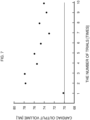
Fig. 7 is a graph showing the result of the basic experiment illustrated inFig. 6 . - An embodiment of the present invention will be described below in detail with reference to the drawings. Any methods for treatment of the human or animal body by surgery or therapy mentioned in the following are not encompassed by the wording of the claims but are considered as useful for understanding the invention.
- Referring to
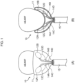
Fig. 1A and Fig. 1B , apumping function unit 10 is configured of: adiaphragm 11 made of a flexible membrane whose size is set to fit an external shape of a lower heart part of a target person (such as a patient whose cardiac output function has degraded significantly due to a myocardial infarction); fourcompression balloons 12A to 12D which are respectively pasted at specified positions on an inner wall surface of thediaphragm 11; and atubular joint 15 that bundles and receives an air supply passage 13, which communicates with an end of thediaphragm 11 andtubes 14A to 14D which are drawn from therespective compression balloons 12A to 12D. - The
tubular joint 15 has a hollow part into which thediaphragm 11 and therespective compression balloons 12A to 12D are collectively stuffed; and thediaphragm 11 and the respectivecompression balloons 12Ato 12D are designed to expand and be discharged from the top end side of thetubular joint 15 by increasing an air pressure inside thediaphragm 11. - The
respective compression balloons 12A to 12D are pasted respectively at specified positions on an inner wall surface of thediaphragm 11 so that they are positioned opposite right and left atriums and ventricles, respectively, when the lower heart part is covered and wrapped with thediaphragm 11. - Under this circumstance, the
diaphragm 11 is designed so that its entire membrane flexes according to the air pressure; however, a material with a very low degree of expansion and contraction (that is, a low modulus of elasticity) is selected. Examples of a desired material to be selected include organic or inorganic polymeric fiber materials and polymeric conjugated fiber materials which have no property causing damage to a living body. Artificial leather, imitation leather, or synthetic leather can also be applied as long as they have no property causing damage to a living body. - The
respective compression balloons 12A to 12D are formed of, for example, silicone rubber and are designed to expand or contract as caused by water discharged or absorbed via thetubes 14A to 14D fromsecond drive units 23A to 23D (Fig. 4 ) described later. - Practically, with the
pumping function unit 10 as illustrated inFig. 2A to Fig. 2C , thediaphragm 11 and therespective compression balloons 12A to 12D are stuffed into the hollow part of the tubular joint 15 in advance. When doing so, thediaphragm 11 is stuffed into the hollow part of the tubular joint 15 with reference to a mark assigned to the top end of the tubular joint 15 by defining a positional relationship between therespective compression balloons 12A to 12D; and when locating the top end of the tubular joint 15 at the lower heart part, the mark is positioned in conformity with the positions of the right and left ventricles. - As a result, when a doctor or the like inserts the tubular joint 15 to attach the
pumping function unit 10 to the target person's chest, they can easily position therespective compression balloons 12A to 12D at the right and left atriums and ventricles of the heart after filling thediaphragm 11 with air simply by positioning them at the lower heart part with reference to the mark. - Specifically speaking, regarding the
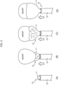
pumping function unit 10, when the top end of the tubular joint 15 (Fig. 3A ), in which thediaphragm 11 and therespective compression balloons 12A to 12D are stuffed, is located at the target person's lower heart part (Fig. 3B ), the first drive unit 22 (Fig. 4 ) described later starts to press air into thediaphragm 11 and the lower heart part is gradually covered and wrapped with the diaphragm 11 (Fig. 3C ). Subsequently, when thediaphragm 11 covers and wraps the lower heart part and therespective compression balloons 12A to 12D are positioned at the right and left atriums and ventricles of the heart, pressing the air into thediaphragm 11 is stopped (Fig. 3D ). - Incidentally, when the
diaphragm 11 covers and wraps the lower heart part and therespective compression balloons 12A to 12D are positioned at the right and left atriums and ventricles of the heart at the target person's lower heart part and if the actualrespective compression balloons 12A to 12D are deviated from the positions of the right and left atriums and ventricles of the heart even though they were positioned with reference to the aforementioned mark, the doctor or the like may adjust the positions of the compression balloons 12A to 12D corresponding to the right and left atriums and ventricles under the X-ray environment. -
Fig. 4 illustrates an overall configuration of a cardiacoutput support apparatus 20. The cardiacoutput support apparatus 20 includes: acontrol unit 21 that controls the entire apparatus; thepumping function unit 10 that supports the pumping function of the target person's heart; and thefirst drive unit 22 and thesecond drive units 23A to 23D that drive thediaphragm 11 and therespective compression balloons 12A to 12D, respectively, of thepumping function unit 10 to make them expand and contract. - The first drive unit 22: is configured of an
air pressure actuator 24 which is composed of a servo motor, and anair compression tank 25; and is driven to press the air into thediaphragm 11 through atube 26. - Practically, in the state where the top end of the tubular joint 15 is interposed into the target person's chest and located at the lower heart part, the first drive unit 22: pushes the
diaphragm 11 out from the top end of the tubular joint 15 while pressing the air into thediaphragm 11 under the control of thecontrol unit 21 and simultaneously causes thediaphragm 11 to start flexing to cover and wrap the lower heart part; and stops pressing the air into thediaphragm 11 at the time point where therespective compression balloons 12A to 12D are positioned at the right and left ventricles of the heart. - The
second drive units 23A to 23D are provided for the left atrium, the left ventricle, the right atrium, and the right ventricle, respectively, corresponding to the compression balloons 12A to 12D. Each of thesesecond drive units 23A to 23D: is configured of, as illustrated inFig. 5 , an actuator (for the left atrium, the left ventricle, the right atrium, and the right ventricle) 30 which is composed of a servo motor, and acylinder 31 which is filled with water inside and is capable of reciprocating linear motions; and is driven to eject or absorb water to or from therelevant compression balloon 12A to 12D while adjusting a cardiac output support amount according to angular control of theactuator 30. - Practically, each
second drive unit 23A to 23D supports the heart's pumping function by adjusting the timing to control compression or relaxation of the right and left atriums and ventricles of the heart while alternately repeating an ejecting operation to fill therelevant compression balloon 12A to 12D with water and make them expand and an absorbing operation to cause therelevant compression balloon 12A to 12D to discharge the water and contract under the control of thecontrol unit 21. - As each
second drive unit 23A to 23D ejects water to therelevant compression balloon 12A to 12D, thecontrol unit 21 is designed to adjust a water discharge amount and discharge timing from the correspondingcylinder 31 while servo-controlling each actuator 30 in synchronization with the heart beats, so that the blood in a cardiac output volume of 70 [ml] or more for one output in blood circulation of a general adult male's heart can be repeatedly output from the heart. - Moreover, the cardiac
output support apparatus 20 is provided with an optical arterialblood measurement unit 40 capable of non-invasive measurement through the target person's skin surface when the tubular joint 15 is inserted to near the target person's lower heart part, so that a measurement result is sent to thecontrol unit 21 while measuring the target person's pulse rate and arterial oxygen saturation. - The
control unit 21 controls eachsecond drive unit 23A to 23D on the basis of the measurement result obtained from the arterial blood measurement unit and independently adjusts the cardiac output and the cardiac output cycle with respect to therespective compression balloons 12A to 12D. - As a result, the cardiac
output support apparatus 20 can control therespective compression balloons 12A to 12D in accordance with a blood circulation condition of the target person and suppress degradation of the heart's pumping function (the blood receiving function and the blood sending function) while letting the right and left atriums and ventricles of the heart contract or relax. - Furthermore, the cardiac
output support apparatus 20 is provided with a cardiaccondition detection unit 41 which has a flexible electrode interposed on an adhesive surface of eachcompression balloon 12A to 12D relative to thediaphragm 11, so that a detection result is sent to thecontrol unit 21 while detecting a disease condition of the target person's heart. - The
control unit 21 controls eachsecond drive unit 23A to 23D on the basis of the measurement result obtained from the cardiaccondition detection unit 41 and controls therespective compression balloons 12A to 12D independently in a specified cardiac output cycle and with specified cardiac output. - As a result, the cardiac
output support apparatus 20 can control the sequential order and the degree of compression of therespective compression balloons 12A to 12D in accordance with the disease condition of the target person's heart and suppress degradation of the heart's pumping function while letting the right and left atriums and ventricles of the heart contract or relax. - Whether the cardiac output of the blood in one output of the cardiac output volume of 70 [ml] or more of an adult male can be repeatedly supported or not is checked by the following experiment by actually using the cardiac
output support apparatus 20 according to the present invention. A model system which simulates a circulatory system is constructed as a heart model by simulating the degree of hardness of an actual heart, blocking blood vessels of a left heart system other than an aorta and a pulmonary vein, and filling the left heart system with water; and also the heart model in which balloons containing water are inserted in a right ventricle is prepared. Valves of this heart model are simulated to prevent a reverse flow by closing the pulmonary vein when compressing the heart. - Referring to
Fig. 6 , practically with thisheart model 50, anaorta 50A is closed with atube clip 51, the left heart system is filled with water, and theheart model 50 is caused to expand. Subsequently, apulmonary vein 50B is closed with atube clip 52 and thetube clip 51 of theaorta 50A is released. The cardiacoutput support apparatus 20 according to this embodiment is applied in this state and therespective compression balloons 12A to 12D are compressed against theheart model 50 to cause the water in theheart model 50 to be discharged. - As a result of trying a cardiac output support operation by using this cardiac
output support apparatus 20 ten times, an amount of water discharged from theheart model 50 was 70 [ml] or more in all the trials as illustrated inFig. 7 . According to this experiment result, it has been confirmed by this experiment result that the cardiacoutput support apparatus 20 according to this embodiment has the performance capable of sufficiently securing the cardiac output volume by the pumping function of theheart model 50. - Incidentally, if the fluid inside the heart is blood, it is predicted that the blood has high viscosity and can hardly be discharged; however, it has already been confirmed that this can be handled by increasing the amount of water to be supplied to each compression balloon.
- Regarding the cardiac
output support apparatus 20 with the above-described configuration, after part of the chest corresponding to the lower heart part of the patient whose cardiac output function has deteriorated significantly due to the myocardial infarction is slightly incised, the tubular joint in which thediaphragm 11 and therespective compression balloons 12A to 12D are stuffed is inserted into the incised part and is located at the lower heart part. - In this state, the
control unit 21 controls thefirst drive unit 22 to: push thediaphragm 11 out from the top end of the tubular joint 15 while pressing the air into thediaphragm 11 and causes thediaphragm 11 to start flexing to cover and wrap the lower heart part; and stop pressing the air into thediaphragm 11 at the time point where therespective compression balloons 12A to 12D are positions at the right and left atriums and ventricles of the heart. - Subsequently, the
control unit 21 controls thesecond drive units 23A to 23D to support the heart's pumping function by alternately repeating the ejecting operation to fill therespective compression balloons 12A to 12D with water and make them expand and the absorbing operation to cause therespective compression balloons 12A to 12D to discharge the water and contract. - As a result, the cardiac
output support apparatus 20 can cover and wrap the lower heart part with thediaphragm 11 and simultaneously position therespective compression balloons 12A to 12D by increasing the air pressure inside thediaphragm 1 from outside in the state where the target person's chest is incised along the length approximately equal to the diameter of the tubular joint 15 and the tubular joint 15 is inserted into the incised part. - Consequently, if the cardiac
output support apparatus 20 is employed, it becomes no longer necessary to incise the target person's chest along the length equal to or longer than the width of the heart; and, therefore, even a doctor who is not a cardiovascular surgery medical specialist can perform the operation and secure the sufficient amount of blood to the heart and it is possible to minimize damage to the target person's heart. - Incidentally, this embodiment has described the case where the four
compression balloons 12Ato 12D corresponding to the right and left atriums and ventricles are pasted on thediaphragm 11 of thepumping function unit 10 and are respectively independently driven in synchronization with the heart beats; however, the present invention is not limited to this example and only either the compression balloons for the left heart (the left atrium and the left ventricle) or the compression balloons for the right heart (the right atrium and the right ventricle) may be driven. As a result, for example, the right heart support and the left heart support may be executed or stopped respectively independently by: performing the support of both the hearts if the patient's condition is bad; and switching to the support of only the left heart if the patient's condition is recovering. - Moreover, this embodiment has described the case where its entire membrane of the
diaphragm 11 flexes according to the air pressure, but a material with a very low degree of expansion and contraction (that is, a low modulus of elasticity) is selected; however, the present invention is not limited to this example and a peripheral region of thediaphragm 11 which does not enter into direct contact with the heart when thediaphragm 11 covers and wraps the lower heart part may be formed of a material with flexibility and non-pliability. - As a result, with the cardiac
output support apparatus 20, when therespective compression balloons 12A to 12D are filled with the fluid and are made to expand, it is possible to prevent the peripheral region of thediaphragm 11 from expanding and pushing the surroundings of the heart towards outside, and avoid compression to the surroundings of the target person's heart. - Furthermore, this embodiment has described the case where each
compression balloon 12Ato 12D is configured of a material with flexibility and pliability such as silicone rubber; however, the present invention is not limited to this example and a whole or part of the exposed portion of eachrespective compression balloon 12A to 12D other than its abutting region in contact with thediaphragm 11 may be formed of a material with flexibility and non-pliability. - As a result, with the cardiac
output support apparatus 20, when therespective compression balloons 12A to 12D are filled with the fluid and are made to expand, therespective compression balloons 12A to 12D themselves expand only towards the direction opposite thediaphragm 11; and, therefore, it is possible to prevent the peripheral region of thediaphragm 11 from expanding and pushing the surroundings of the heart towards outside, and avoid compression on the surroundings of the target's heart. - Furthermore, this embodiment has described the case where after a part of the chest corresponding to the target person's lower heart part is slightly incised under the normal surgical operation environment, the tubular joint 15 in which the
diaphragm 11 and therespective compression balloons 12A to 12D are stuffed is inserted and located at the lower heart part; however, the present invention is not limited to this example and a freely expandable and contractable mesh-like material whose size is set to fit the external shape of the target person's lower heart part may be used to cover and wrap the lower heart part before inserting the tubular joint 15. - Under the above-described circumstance, a doctor or the like needs to handle the mesh-like material with their fingertips under the environment by X-ray imaging so that coronary arteries of the target person's lower heart part are exposed through gaps in the mesh-like material, in other words, a mesh fabric of the mesh-like material will not cover the coronary arteries. As a result, when the target person's lower heart part which is covered and wrapped with the mesh-like material is then covered and wrapped with the
diaphragm 11 and its internal air pressure is increased, it is possible to avoid the occurrence of any damage due to the compression on the coronary arteries of the lower heart part even if the ejecting operation and the absorbing operation by therespective compression balloons 12A to 12D are performed. - Moreover, this embodiment has described the case where the water which is an incompressible fluid is used as the fluid in the
respective compression balloons 12A to 12D; however, the present invention is not limited to this example and any liquid other than the water may be used as long as it is the incompressible fluid regarding which safety for the human body can be secured. - Furthermore, this embodiment has described the case where the air is applied as the gas which is pressed into the
diaphragm 11; however, the present invention is not limited to this example and any gas such as a helium gas may be used as long as it does not affect the human body. -
- 10:
- pumping function unit
- 11:
- diaphragm
- 12A to 12D:
- compression balloons
- 13:
- air supply passage
- 14A to 14D:
- tubes
- 15:
- tubular joint
- 20:
- cardiac output support apparatus
- 21:
- control unit
- 22:
- first drive unit
- 23A to 23D:
- second drive units
- 30:
- servo motor
- 31:
- cylinder
- 40:
- arterial blood measurement unit
- 41:
- cardiac condition detection unit
- 50:
- heart model
Claims (7)
- A cardiac output support apparatus (20) comprising:a diaphragm (11) whose size is set to fit an external shape of a lower heart part of a target person and which is composed of a flexible membrane that is responsive to a gas pressure;a plurality of compression balloons (12A to 12D) which are pasted at specified positions of an inner wall surface of the diaphragm so that the compression balloons are positioned opposite atriums and ventricles of a heart, respectively, when the lower heart part is covered and wrapped with the diaphragm;a first drive unit (22) that is driven to press gas into the diaphragm;second drive units (23A to 23D) that are driven to eject or absorb a fluid to or from the compression balloons, respectively; anda tubular joint (15) with a hollow part in which the diaphragm and each of the compression balloons are collectively stuffed in advance,wherein the first drive unit is configured to, in a state where a top end of the tubular joint is interposed in a chest of the target person and is located at the lower heart part, push the diaphragm out from the top end of the tubular joint while pressing the gas into the diaphragm, and to simultaneously cause the diaphragm to start flexing to cover and wrap the lower heart part, and to then stop pressing the gas into the diaphragm at a time point where the compression balloons are positioned at the atriums and the ventricles of the heart, respectively; andwherein the second drive units are configured to support a pumping function of the heart by alternately repeating an ejecting operation to fill each of the compression balloons with the fluid and cause each compression balloon to expand and an absorbing operation to cause each compression balloon to discharge the fluid and contract.
- The cardiac output support apparatus according to claim 1,
wherein a peripheral region of the diaphragm which does not enter into direct contact with the heart when covering and wrapping the lower heart part is formed of a material having flexibility and non-pliability. - The cardiac output support apparatus according to claim 2,
wherein a whole or part of an exposed portion of each compression balloon other than its abutting region in contact with the diaphragm is formed of a material having flexibility and non-pliability. - The cardiac output support apparatus according to any one of claims 1 to 3, further comprising an arterial blood measurement unit (40) configured to measure a pulse rate and arterial oxygen saturation of the target person, wherein each of the second drive units is configured to independently adjust a cardiac output and a cardiac output cycle with respect to each compression balloon in accordance with a measurement result of the arterial blood measurement unit.
- The cardiac output support apparatus according to any one of claims 1 to 4, further comprising a cardiac condition detection unit (41) configured to detect a disease condition of the heart of the target person, wherein each of the second drive units is configured to independently control each compression balloon in a specified cardiac output cycle and with a specified cardiac output on the basis of a detection state of the cardiac condition detection unit.
- The cardiac output support apparatus according to any one of claims 1 to 5,wherein the diaphragm is stuffed into the hollow part of the tubular joint with reference to a mark assigned to the top end of the tubular joint by defining a positional relationship between the respective compression balloons; andwherein when the top end of the tubular joint is located at the lower heart part, the mark is positioned in conformity with positions of the atriums and the ventricles.
- The cardiac output support apparatus according to any one of claims 1 to 6,
wherein a freely expandable and contractable mesh-like material whose size is set to fit the external shape of the lower heart part of the target person is made to cover and wrap the lower heart part in such a manner that coronary arteries are exposed from gaps under an environment of X-ray imaging; and the diaphragm is made to further cover and wrap a surface of the mesh-like material.
Applications Claiming Priority (2)
| Application Number | Priority Date | Filing Date | Title |
|---|---|---|---|
| JP2018162211 | 2018-08-30 | ||
| PCT/JP2019/034226 WO2020045654A1 (en) | 2018-08-30 | 2019-08-30 | Cardiac pumping assistance device |
Publications (3)
| Publication Number | Publication Date |
|---|---|
| EP3845255A1 EP3845255A1 (en) | 2021-07-07 |
| EP3845255A4 EP3845255A4 (en) | 2022-05-18 |
| EP3845255B1 true EP3845255B1 (en) | 2023-03-15 |
Family
ID=69643896
Family Applications (1)
| Application Number | Title | Priority Date | Filing Date |
|---|---|---|---|
| EP19855486.7A Active EP3845255B1 (en) | 2018-08-30 | 2019-08-30 | Cardiac pumping assistance device |
Country Status (4)
| Country | Link |
|---|---|
| US (1) | US11980751B2 (en) |
| EP (1) | EP3845255B1 (en) |
| JP (1) | JP7057925B2 (en) |
| WO (1) | WO2020045654A1 (en) |
Families Citing this family (2)
| Publication number | Priority date | Publication date | Assignee | Title |
|---|---|---|---|---|
| KR101695674B1 (en) * | 2015-07-17 | 2017-01-12 | 배병철 | Removing device for ballast of rail |
| WO2023212148A1 (en) * | 2022-04-28 | 2023-11-02 | Corinnova Incorporated | Method and device for the optimization of loading a cardiac assist device |
Family Cites Families (26)
| Publication number | Priority date | Publication date | Assignee | Title |
|---|---|---|---|---|
| US4690134A (en) * | 1985-07-01 | 1987-09-01 | Snyders Robert V | Ventricular assist device |
| EP0852940A3 (en) * | 1992-05-19 | 1998-11-18 | Inc. Cardio Technologies | Heart massage apparatus |
| JPH10174713A (en) * | 1996-12-17 | 1998-06-30 | Buaayu:Kk | Heart assisting device |
| JP3935541B2 (en) * | 1996-12-17 | 2007-06-27 | 株式会社ヴァーユ | Cardiac assist device |
| US6063115A (en) * | 1997-04-11 | 2000-05-16 | Medtronic, Inc. | Cardiac assistance system |
| US6095968A (en) * | 1998-04-10 | 2000-08-01 | Cardio Technologies, Inc. | Reinforcement device |
| AU8126898A (en) * | 1998-07-07 | 2000-01-24 | Pulsecare Ltd. | Minimal invasive cardiac massage device |
| US6432039B1 (en) | 1998-12-21 | 2002-08-13 | Corset, Inc. | Methods and apparatus for reinforcement of the heart ventricles |
| US6540659B1 (en) * | 2000-11-28 | 2003-04-01 | Abiomed, Inc. | Cardiac assistance systems having bi-directional pumping elements |
| US7860555B2 (en) | 2005-02-02 | 2010-12-28 | Voyage Medical, Inc. | Tissue visualization and manipulation system |
| CN101336119A (en) * | 2005-11-28 | 2008-12-31 | 米奥特克有限责任公司 | Method and apparatus for minimally invasive direct mechanical ventricular actuation |
| CN101939050B (en) * | 2008-01-08 | 2013-07-03 | 国立成功大学 | Cardiac compression system |
| CA2824889C (en) | 2008-09-15 | 2020-07-07 | Anders Jonsson | Medical device, method and system for temporary occlusion of an opening in a lumen of a body |
| US10583234B2 (en) | 2008-10-10 | 2020-03-10 | Peter Forsell | Heart help device, system and method |
| EP3851076A1 (en) | 2008-10-10 | 2021-07-21 | MedicalTree Patent Ltd. | An improved artificial valve |
| US8523756B2 (en) * | 2008-12-31 | 2013-09-03 | National Cheng Kung University | Cardiac compression system |
| EP2456506B1 (en) | 2009-07-22 | 2019-10-16 | The Texas A&M University System | Biphasic and dynamic adjustable support devices with assist and recoil capabilities for treatment of cardiac pathologies |
| DE102013200149A1 (en) * | 2013-01-08 | 2014-07-24 | AdjuCor GmbH | Cardiac assistance device having a chamber with a bellows-shaped portion |
| US9220824B2 (en) * | 2013-01-08 | 2015-12-29 | AdjuCor GmbH | Implanting cardiac devices |
| DE102013200151A1 (en) * | 2013-01-08 | 2014-07-10 | AdjuCor GmbH | Heart support device with markings |
| DE102013200154A1 (en) | 2013-01-08 | 2014-07-10 | AdjuCor GmbH | A heart support device having a shell and first and second sheaths |
| DE102013200148A1 (en) * | 2013-01-08 | 2014-07-10 | AdjuCor GmbH | Plug system for a cardiac assist device |
| JP6773953B2 (en) | 2015-02-19 | 2020-10-21 | 学校法人 久留米大学 | Auxiliary heart device |
| US10463496B2 (en) * | 2015-07-15 | 2019-11-05 | The Texas A&M University System | Self-expanding heart assist device |
| WO2017223485A1 (en) | 2016-06-23 | 2017-12-28 | The Texas A&M University System | Fully implantable direct myocardium assist device |
| US11382752B2 (en) * | 2019-01-18 | 2022-07-12 | Rex Medical, L.P. | Minnimally invasive device for treating chronic heart failure |
-
2019
- 2019-08-30 JP JP2020539645A patent/JP7057925B2/en active Active
- 2019-08-30 US US17/271,968 patent/US11980751B2/en active Active
- 2019-08-30 WO PCT/JP2019/034226 patent/WO2020045654A1/en unknown
- 2019-08-30 EP EP19855486.7A patent/EP3845255B1/en active Active
Also Published As
| Publication number | Publication date |
|---|---|
| JP7057925B2 (en) | 2022-04-21 |
| US11980751B2 (en) | 2024-05-14 |
| EP3845255A4 (en) | 2022-05-18 |
| US20210338998A1 (en) | 2021-11-04 |
| JPWO2020045654A1 (en) | 2021-08-12 |
| EP3845255A1 (en) | 2021-07-07 |
| WO2020045654A1 (en) | 2020-03-05 |
Similar Documents
| Publication | Publication Date | Title |
|---|---|---|
| US10058647B2 (en) | Biomimetic actuation device and system, and methods for controlling a biomimetic actuation device and system | |
| RU2703701C2 (en) | Heart supporting device | |
| JP4871917B2 (en) | Cardiac assist system | |
| US10376681B2 (en) | Vacuum-based compliance restoration | |
| EP2785393B1 (en) | A non-blood contacting mechanical device that improves heart function after injury | |
| US6918870B1 (en) | Assist device for the failing heart | |
| WO2000036995A2 (en) | Method and apparatus for reinforcement of the heart ventricles | |
| US20060178604A1 (en) | Blood pumping system | |
| US6149578A (en) | Piston-action intra-aortic coronary assist device | |
| EP3845255B1 (en) | Cardiac pumping assistance device | |
| US8523756B2 (en) | Cardiac compression system | |
| CN102107030B (en) | Cardiac impulse assist device, cardiac impulse assist system and method for treating cardiac failure | |
| CA2566813C (en) | Device for epicardial support and/or the assuming of cardiac activity | |
| WO2011100180A1 (en) | Extra-cardiac differential ventricular actuation by inertial and baric partitioning | |
| EP2229213A1 (en) | Cardiac compression system | |
| US20080045866A1 (en) | External left ventricular assist device for treatment of congestive heart failure | |
| EP3651826B1 (en) | Intracardiac pump | |
| US20080242916A1 (en) | Eecp Device and an Image System Comprising the Same | |
| WO1998030271A1 (en) | Apparatus for cardiac treatment | |
| CN201572358U (en) | Cardiac impulse assisting device and cardiac impulse assisting system | |
| US20170258593A1 (en) | Cardiac assistance device | |
| US20190209759A1 (en) | Ventricular assist devices | |
| AU742406B2 (en) | An assist device for the failing heart |
Legal Events
| Date | Code | Title | Description |
|---|---|---|---|
| STAA | Information on the status of an ep patent application or granted ep patent |
Free format text: STATUS: THE INTERNATIONAL PUBLICATION HAS BEEN MADE |
|
| STAA | Information on the status of an ep patent application or granted ep patent |
Free format text: STATUS: REQUEST FOR EXAMINATION WAS MADE |
|
| PUAI | Public reference made under article 153(3) epc to a published international application that has entered the european phase |
Free format text: ORIGINAL CODE: 0009012 |
|
| 17P | Request for examination filed |
Effective date: 20210316 |
|
| AK | Designated contracting states |
Kind code of ref document: A1 Designated state(s): AL AT BE BG CH CY CZ DE DK EE ES FI FR GB GR HR HU IE IS IT LI LT LU LV MC MK MT NL NO PL PT RO RS SE SI SK SM TR |
|
| DAV | Request for validation of the european patent (deleted) | ||
| DAX | Request for extension of the european patent (deleted) | ||
| A4 | Supplementary search report drawn up and despatched |
Effective date: 20220422 |
|
| RIC1 | Information provided on ipc code assigned before grant |
Ipc: A61M 60/865 20210101ALI20220414BHEP Ipc: A61M 60/839 20210101ALI20220414BHEP Ipc: A61M 60/515 20210101ALI20220414BHEP Ipc: A61M 60/468 20210101ALI20220414BHEP Ipc: A61M 60/289 20210101ALI20220414BHEP Ipc: A61M 60/191 20210101AFI20220414BHEP |
|
| REG | Reference to a national code |
Ref country code: DE Ref legal event code: R079 Ref document number: 602019026520 Country of ref document: DE Free format text: PREVIOUS MAIN CLASS: A61M0001100000 Ipc: A61M0060191000 |
|
| GRAP | Despatch of communication of intention to grant a patent |
Free format text: ORIGINAL CODE: EPIDOSNIGR1 |
|
| RIC1 | Information provided on ipc code assigned before grant |
Ipc: A61M 60/865 20210101ALI20220916BHEP Ipc: A61M 60/839 20210101ALI20220916BHEP Ipc: A61M 60/515 20210101ALI20220916BHEP Ipc: A61M 60/468 20210101ALI20220916BHEP Ipc: A61M 60/289 20210101ALI20220916BHEP Ipc: A61M 60/191 20210101AFI20220916BHEP |
|
| STAA | Information on the status of an ep patent application or granted ep patent |
Free format text: STATUS: GRANT OF PATENT IS INTENDED |
|
| INTG | Intention to grant announced |
Effective date: 20221027 |
|
| GRAS | Grant fee paid |
Free format text: ORIGINAL CODE: EPIDOSNIGR3 |
|
| GRAA | (expected) grant |
Free format text: ORIGINAL CODE: 0009210 |
|
| STAA | Information on the status of an ep patent application or granted ep patent |
Free format text: STATUS: THE PATENT HAS BEEN GRANTED |
|
| AK | Designated contracting states |
Kind code of ref document: B1 Designated state(s): AL AT BE BG CH CY CZ DE DK EE ES FI FR GB GR HR HU IE IS IT LI LT LU LV MC MK MT NL NO PL PT RO RS SE SI SK SM TR |
|
| REG | Reference to a national code |
Ref country code: CH Ref legal event code: EP Ref country code: GB Ref legal event code: FG4D |
|
| REG | Reference to a national code |
Ref country code: DE Ref legal event code: R096 Ref document number: 602019026520 Country of ref document: DE |
|
| REG | Reference to a national code |
Ref country code: IE Ref legal event code: FG4D |
|
| REG | Reference to a national code |
Ref country code: AT Ref legal event code: REF Ref document number: 1553640 Country of ref document: AT Kind code of ref document: T Effective date: 20230415 |
|
| REG | Reference to a national code |
Ref country code: LT Ref legal event code: MG9D |
|
| REG | Reference to a national code |
Ref country code: NL Ref legal event code: MP Effective date: 20230315 |
|
| PG25 | Lapsed in a contracting state [announced via postgrant information from national office to epo] |
Ref country code: RS Free format text: LAPSE BECAUSE OF FAILURE TO SUBMIT A TRANSLATION OF THE DESCRIPTION OR TO PAY THE FEE WITHIN THE PRESCRIBED TIME-LIMIT Effective date: 20230315 Ref country code: NO Free format text: LAPSE BECAUSE OF FAILURE TO SUBMIT A TRANSLATION OF THE DESCRIPTION OR TO PAY THE FEE WITHIN THE PRESCRIBED TIME-LIMIT Effective date: 20230615 Ref country code: LV Free format text: LAPSE BECAUSE OF FAILURE TO SUBMIT A TRANSLATION OF THE DESCRIPTION OR TO PAY THE FEE WITHIN THE PRESCRIBED TIME-LIMIT Effective date: 20230315 Ref country code: LT Free format text: LAPSE BECAUSE OF FAILURE TO SUBMIT A TRANSLATION OF THE DESCRIPTION OR TO PAY THE FEE WITHIN THE PRESCRIBED TIME-LIMIT Effective date: 20230315 Ref country code: HR Free format text: LAPSE BECAUSE OF FAILURE TO SUBMIT A TRANSLATION OF THE DESCRIPTION OR TO PAY THE FEE WITHIN THE PRESCRIBED TIME-LIMIT Effective date: 20230315 |
|
| REG | Reference to a national code |
Ref country code: AT Ref legal event code: MK05 Ref document number: 1553640 Country of ref document: AT Kind code of ref document: T Effective date: 20230315 |
|
| PG25 | Lapsed in a contracting state [announced via postgrant information from national office to epo] |
Ref country code: SE Free format text: LAPSE BECAUSE OF FAILURE TO SUBMIT A TRANSLATION OF THE DESCRIPTION OR TO PAY THE FEE WITHIN THE PRESCRIBED TIME-LIMIT Effective date: 20230315 Ref country code: NL Free format text: LAPSE BECAUSE OF FAILURE TO SUBMIT A TRANSLATION OF THE DESCRIPTION OR TO PAY THE FEE WITHIN THE PRESCRIBED TIME-LIMIT Effective date: 20230315 Ref country code: GR Free format text: LAPSE BECAUSE OF FAILURE TO SUBMIT A TRANSLATION OF THE DESCRIPTION OR TO PAY THE FEE WITHIN THE PRESCRIBED TIME-LIMIT Effective date: 20230616 Ref country code: FI Free format text: LAPSE BECAUSE OF FAILURE TO SUBMIT A TRANSLATION OF THE DESCRIPTION OR TO PAY THE FEE WITHIN THE PRESCRIBED TIME-LIMIT Effective date: 20230315 |
|
| PG25 | Lapsed in a contracting state [announced via postgrant information from national office to epo] |
Ref country code: SM Free format text: LAPSE BECAUSE OF FAILURE TO SUBMIT A TRANSLATION OF THE DESCRIPTION OR TO PAY THE FEE WITHIN THE PRESCRIBED TIME-LIMIT Effective date: 20230315 Ref country code: RO Free format text: LAPSE BECAUSE OF FAILURE TO SUBMIT A TRANSLATION OF THE DESCRIPTION OR TO PAY THE FEE WITHIN THE PRESCRIBED TIME-LIMIT Effective date: 20230315 Ref country code: PT Free format text: LAPSE BECAUSE OF FAILURE TO SUBMIT A TRANSLATION OF THE DESCRIPTION OR TO PAY THE FEE WITHIN THE PRESCRIBED TIME-LIMIT Effective date: 20230717 Ref country code: ES Free format text: LAPSE BECAUSE OF FAILURE TO SUBMIT A TRANSLATION OF THE DESCRIPTION OR TO PAY THE FEE WITHIN THE PRESCRIBED TIME-LIMIT Effective date: 20230315 Ref country code: EE Free format text: LAPSE BECAUSE OF FAILURE TO SUBMIT A TRANSLATION OF THE DESCRIPTION OR TO PAY THE FEE WITHIN THE PRESCRIBED TIME-LIMIT Effective date: 20230315 Ref country code: CZ Free format text: LAPSE BECAUSE OF FAILURE TO SUBMIT A TRANSLATION OF THE DESCRIPTION OR TO PAY THE FEE WITHIN THE PRESCRIBED TIME-LIMIT Effective date: 20230315 Ref country code: AT Free format text: LAPSE BECAUSE OF FAILURE TO SUBMIT A TRANSLATION OF THE DESCRIPTION OR TO PAY THE FEE WITHIN THE PRESCRIBED TIME-LIMIT Effective date: 20230315 |
|
| PGFP | Annual fee paid to national office [announced via postgrant information from national office to epo] |
Ref country code: IT Payment date: 20230726 Year of fee payment: 5 Ref country code: GB Payment date: 20230816 Year of fee payment: 5 |
|
| PG25 | Lapsed in a contracting state [announced via postgrant information from national office to epo] |
Ref country code: SK Free format text: LAPSE BECAUSE OF FAILURE TO SUBMIT A TRANSLATION OF THE DESCRIPTION OR TO PAY THE FEE WITHIN THE PRESCRIBED TIME-LIMIT Effective date: 20230315 Ref country code: PL Free format text: LAPSE BECAUSE OF FAILURE TO SUBMIT A TRANSLATION OF THE DESCRIPTION OR TO PAY THE FEE WITHIN THE PRESCRIBED TIME-LIMIT Effective date: 20230315 Ref country code: IS Free format text: LAPSE BECAUSE OF FAILURE TO SUBMIT A TRANSLATION OF THE DESCRIPTION OR TO PAY THE FEE WITHIN THE PRESCRIBED TIME-LIMIT Effective date: 20230715 |
|
| PGFP | Annual fee paid to national office [announced via postgrant information from national office to epo] |
Ref country code: DE Payment date: 20230825 Year of fee payment: 5 |
|
| REG | Reference to a national code |
Ref country code: DE Ref legal event code: R097 Ref document number: 602019026520 Country of ref document: DE |
|
| PLBE | No opposition filed within time limit |
Free format text: ORIGINAL CODE: 0009261 |
|
| STAA | Information on the status of an ep patent application or granted ep patent |
Free format text: STATUS: NO OPPOSITION FILED WITHIN TIME LIMIT |
|
| PG25 | Lapsed in a contracting state [announced via postgrant information from national office to epo] |
Ref country code: SI Free format text: LAPSE BECAUSE OF FAILURE TO SUBMIT A TRANSLATION OF THE DESCRIPTION OR TO PAY THE FEE WITHIN THE PRESCRIBED TIME-LIMIT Effective date: 20230315 Ref country code: DK Free format text: LAPSE BECAUSE OF FAILURE TO SUBMIT A TRANSLATION OF THE DESCRIPTION OR TO PAY THE FEE WITHIN THE PRESCRIBED TIME-LIMIT Effective date: 20230315 |
|
| 26N | No opposition filed |
Effective date: 20231218 |
|
| PG25 | Lapsed in a contracting state [announced via postgrant information from national office to epo] |
Ref country code: MC Free format text: LAPSE BECAUSE OF FAILURE TO SUBMIT A TRANSLATION OF THE DESCRIPTION OR TO PAY THE FEE WITHIN THE PRESCRIBED TIME-LIMIT Effective date: 20230315 |
|
| REG | Reference to a national code |
Ref country code: CH Ref legal event code: PL |
|
| PG25 | Lapsed in a contracting state [announced via postgrant information from national office to epo] |
Ref country code: MC Free format text: LAPSE BECAUSE OF FAILURE TO SUBMIT A TRANSLATION OF THE DESCRIPTION OR TO PAY THE FEE WITHIN THE PRESCRIBED TIME-LIMIT Effective date: 20230315 |
|
| PG25 | Lapsed in a contracting state [announced via postgrant information from national office to epo] |
Ref country code: LU Free format text: LAPSE BECAUSE OF NON-PAYMENT OF DUE FEES Effective date: 20230830 |
|
| PG25 | Lapsed in a contracting state [announced via postgrant information from national office to epo] |
Ref country code: LU Free format text: LAPSE BECAUSE OF NON-PAYMENT OF DUE FEES Effective date: 20230830 Ref country code: CH Free format text: LAPSE BECAUSE OF NON-PAYMENT OF DUE FEES Effective date: 20230831 |
|
| REG | Reference to a national code |
Ref country code: BE Ref legal event code: MM Effective date: 20230831 |
|
| REG | Reference to a national code |
Ref country code: IE Ref legal event code: MM4A |