EP3840538B1 - System and method for providing alternative communication path for management of lighting network elements - Google Patents
System and method for providing alternative communication path for management of lighting network elements Download PDFInfo
- Publication number
- EP3840538B1 EP3840538B1 EP21150944.3A EP21150944A EP3840538B1 EP 3840538 B1 EP3840538 B1 EP 3840538B1 EP 21150944 A EP21150944 A EP 21150944A EP 3840538 B1 EP3840538 B1 EP 3840538B1
- Authority
- EP
- European Patent Office
- Prior art keywords
- communication network
- network
- command
- received
- alternative communication
- Prior art date
- Legal status (The legal status is an assumption and is not a legal conclusion. Google has not performed a legal analysis and makes no representation as to the accuracy of the status listed.)
- Active
Links
- 238000004891 communication Methods 0.000 title claims description 119
- 238000000034 method Methods 0.000 title claims description 28
- 238000005286 illumination Methods 0.000 claims description 15
- 230000004044 response Effects 0.000 claims description 12
- 238000012544 monitoring process Methods 0.000 claims description 10
- 230000008859 change Effects 0.000 description 13
- 238000012545 processing Methods 0.000 description 12
- 230000008569 process Effects 0.000 description 6
- 238000005265 energy consumption Methods 0.000 description 2
- 230000007246 mechanism Effects 0.000 description 2
- 238000013459 approach Methods 0.000 description 1
- 230000006399 behavior Effects 0.000 description 1
- 230000001413 cellular effect Effects 0.000 description 1
- 230000001419 dependent effect Effects 0.000 description 1
- 238000001514 detection method Methods 0.000 description 1
- 230000000694 effects Effects 0.000 description 1
- 230000005611 electricity Effects 0.000 description 1
- 238000005516 engineering process Methods 0.000 description 1
- 238000011156 evaluation Methods 0.000 description 1
- 238000009434 installation Methods 0.000 description 1
- 238000012986 modification Methods 0.000 description 1
- 230000004048 modification Effects 0.000 description 1
- 238000003672 processing method Methods 0.000 description 1
Images

Classifications
-
- H—ELECTRICITY
- H05—ELECTRIC TECHNIQUES NOT OTHERWISE PROVIDED FOR
- H05B—ELECTRIC HEATING; ELECTRIC LIGHT SOURCES NOT OTHERWISE PROVIDED FOR; CIRCUIT ARRANGEMENTS FOR ELECTRIC LIGHT SOURCES, IN GENERAL
- H05B47/00—Circuit arrangements for operating light sources in general, i.e. where the type of light source is not relevant
- H05B47/10—Controlling the light source
- H05B47/165—Controlling the light source following a pre-assigned programmed sequence; Logic control [LC]
-
- G—PHYSICS
- G05—CONTROLLING; REGULATING
- G05B—CONTROL OR REGULATING SYSTEMS IN GENERAL; FUNCTIONAL ELEMENTS OF SUCH SYSTEMS; MONITORING OR TESTING ARRANGEMENTS FOR SUCH SYSTEMS OR ELEMENTS
- G05B15/00—Systems controlled by a computer
- G05B15/02—Systems controlled by a computer electric
-
- H—ELECTRICITY
- H05—ELECTRIC TECHNIQUES NOT OTHERWISE PROVIDED FOR
- H05B—ELECTRIC HEATING; ELECTRIC LIGHT SOURCES NOT OTHERWISE PROVIDED FOR; CIRCUIT ARRANGEMENTS FOR ELECTRIC LIGHT SOURCES, IN GENERAL
- H05B47/00—Circuit arrangements for operating light sources in general, i.e. where the type of light source is not relevant
- H05B47/10—Controlling the light source
- H05B47/155—Coordinated control of two or more light sources
-
- H—ELECTRICITY
- H05—ELECTRIC TECHNIQUES NOT OTHERWISE PROVIDED FOR
- H05B—ELECTRIC HEATING; ELECTRIC LIGHT SOURCES NOT OTHERWISE PROVIDED FOR; CIRCUIT ARRANGEMENTS FOR ELECTRIC LIGHT SOURCES, IN GENERAL
- H05B47/00—Circuit arrangements for operating light sources in general, i.e. where the type of light source is not relevant
- H05B47/10—Controlling the light source
- H05B47/175—Controlling the light source by remote control
- H05B47/18—Controlling the light source by remote control via data-bus transmission
-
- H—ELECTRICITY
- H05—ELECTRIC TECHNIQUES NOT OTHERWISE PROVIDED FOR
- H05B—ELECTRIC HEATING; ELECTRIC LIGHT SOURCES NOT OTHERWISE PROVIDED FOR; CIRCUIT ARRANGEMENTS FOR ELECTRIC LIGHT SOURCES, IN GENERAL
- H05B47/00—Circuit arrangements for operating light sources in general, i.e. where the type of light source is not relevant
- H05B47/10—Controlling the light source
- H05B47/175—Controlling the light source by remote control
- H05B47/185—Controlling the light source by remote control via power line carrier transmission
-
- H—ELECTRICITY
- H05—ELECTRIC TECHNIQUES NOT OTHERWISE PROVIDED FOR
- H05B—ELECTRIC HEATING; ELECTRIC LIGHT SOURCES NOT OTHERWISE PROVIDED FOR; CIRCUIT ARRANGEMENTS FOR ELECTRIC LIGHT SOURCES, IN GENERAL
- H05B47/00—Circuit arrangements for operating light sources in general, i.e. where the type of light source is not relevant
- H05B47/10—Controlling the light source
- H05B47/175—Controlling the light source by remote control
- H05B47/19—Controlling the light source by remote control via wireless transmission
-
- Y—GENERAL TAGGING OF NEW TECHNOLOGICAL DEVELOPMENTS; GENERAL TAGGING OF CROSS-SECTIONAL TECHNOLOGIES SPANNING OVER SEVERAL SECTIONS OF THE IPC; TECHNICAL SUBJECTS COVERED BY FORMER USPC CROSS-REFERENCE ART COLLECTIONS [XRACs] AND DIGESTS
- Y02—TECHNOLOGIES OR APPLICATIONS FOR MITIGATION OR ADAPTATION AGAINST CLIMATE CHANGE
- Y02B—CLIMATE CHANGE MITIGATION TECHNOLOGIES RELATED TO BUILDINGS, e.g. HOUSING, HOUSE APPLIANCES OR RELATED END-USER APPLICATIONS
- Y02B20/00—Energy efficient lighting technologies, e.g. halogen lamps or gas discharge lamps
- Y02B20/72—Energy efficient lighting technologies, e.g. halogen lamps or gas discharge lamps in street lighting
Definitions
- This application is related to the field of lighting network management systems, and more particularly to a method and device to provide reliable communications with lighting network systems.
- CMS Central Management System
- a CMS is best characterized as a communication system for providing 'Monitoring', 'Reporting' and 'Control' of lighting (e.g., street lighting and/or indoor lighting).
- the exact hardware and software required to implement a CMS varies between the different approaches adopted by the various manufacturers producing CMS today.
- Networks for communication and control may be wired or wireless.
- power line and RF communication systems are methods for controlling luminaires in a network.
- the Starsense system manufactured by the assignee of the instant application, is a telemanagement system with remote control of outdoor light points (elements) on highways, roads, streets, and in residential areas.
- the Starsense products save energy by enabling individual light points to be switched on or off at any given time or set to any dimming level.
- the Starsense system is here used as an example of an outdoor lighting system, it would be recognized by those skilled in the art that the invention disclosed herein is also applicable to other types of outdoor and indoor lighting systems with wired or wireless communication and control paths for lighting system behavior management.
- United States patent application US 2011/140611 A1 discloses a lighting control system coupled to one or more ballast/drivers operating one or more light sources.
- a low power control module receives analog, digital and/or DALI signals from one of more sources, processes the signals to provide an appropriate lighting response and outputs one or more commands related to light output of the one or more ballast/drivers operating one or more light sources.
- United States patent application US 2009/0309512 A1 relates to a mechanism for prioritizaiton of DALI signals entering from to separate buses or inputs, wherein upon receipt of signals arriving via the two inputs, the mechanism allocates priorities to the signals on the basis of predetermined criteria, to this end it proposes to temporarily store signals so as to allow evaluation of their priorities and then forward the command having priority to at least one electronic ballast, which in turn processes the control signals further and delivers output sights for a light.
- local control of the luminaries may be required to satisfy certain imposed requirements.
- local control may be implemented with a demand response (DR) operation.
- DR demand response
- Demand response operations can be defined as a set of initiatives that allows electric energy customers to change their electricity usage for a certain period of time due to receiving a price signal from the utility.
- communication with, and control of, luminaires in an outdoor or an indoor system may be interrupted when a primary communication and control path is not available or not applicable at certain periods.
- an alternative communication / control path for the utilities
- the luminaire or to other system components or systems, e.g., police, fire, traffic management, etc., to provide control of the devices in the systems when the primary communication path is not functional.
- the alternative communication/ control path may enable subsidies and incentives, increase energy savings, and meet different set / agreed / needed / enforced targets.
- the present disclosure is directed to methods for controlling a luminaire of an illumination network and devices for controlling a luminaire in an illumination network comprising a plurality of luminaires.
- the invention is set out in the appended set of claims.
- a method for controlling an element of a network comprises monitoring a primary communication network; monitoring an alternative communication network; receiving a command from the primary communication network and another command from the alternative communication network; prioritizing the received commands using a priority setting; and executing an application in response to the prioritized received command, said application controlling the operation of the luminaire and wherein the primary communication network and the alternative communication network are independent the method characterized in that: the primary communication network is either a wired network or wireless network and the alternative communication network is a wireless network and the priority setting involves a setting whereby a first command from the alternative communication network is maintained for at least a predetermined period of time and second commands received from the primary communication network are ignored if received within the predetermined period of time after the first command was received from the alternative communication network.
- the primary communication network is a wireless network and the alternative communication network is a wired network
- a device for controlling an element of a network comprising a plurality of luminaires.
- the device comprising: at least one processor in communication with a memory, the memory including code which when accessed by the at least one processor, causes the at least one processor to: monitor a primary communication network; monitor an alternative communication network; receive a command from the primary communication network and another command from the alternative communication network; prioritize the received commands using a priority setting; and execute an application in response to the prioritized received command, said application controlling the operation of the luminaire and wherein the primary communication network and the alternative communication network are independent the device characterized in that: the primary communication network is either a wired network or wireless network and the alternative communication network is a wireless network and the priority setting involves a setting whereby a first command from the alternative communication network is maintained for at least a predetermined period of time and second commands received from the primary communication network are ignored if received within the predetermined period of time after the first command was received from the alternative communication network.
- the primary communication network is a wireless network and the alternative communication network is a wired network
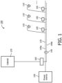
- Figure 1 represents an exemplary illumination system100 including a plurality of outdoor luminaries, 110, wherein each of the illustrated luminaries 110 is connected through a power grid (network) 120.
- the luminaries 110 are connected in a serial manner.
- Figure 1 is one example how an outdoor lighting network can be connected, controlled and/or communicated with the luminaries 110 (network elements) through a power grid 120 that supplies power to the luminaries 110 from power source 150.
- a primary communication network 140 provides control signals to each of the illustrated luminaries 110.
- the primary communication network 140 may be incorporated into the power grid 120, wherein the lines 140a represent the power lines that provide power to the luminaries 110 and the lines 140b represent the (same) power lines that provide control signals to the luminaries 110. It would be recognized that lines 140a and 140b are logic representations of the physical lines of power grid 120 upon which both power and control (information) are implemented.
- the control (or information) signals may be used to turn the luminaries 110 on or off or to dim the luminaires to conserve power.
- Providing communication and/or control (or information) signals over a power line network 120 is well known in the art and need not be discussed in detail herein.
- the primary communication network 140 may be totally independent of the power grid 120 and may be a wired or a wireless system.
- a wire-ed primary communication network 140 may be one of a public network (e.g., internet) or a private network.
- a wireless primary communication network 140 may be a local area network (LAN) or a wide area network (WAN) than may be public or private.
- the luminaries 110 include components that accept the communication provided through the primary communication network 140.
- an electronic cabinet (or a segment controller that is not in the cabinet form) 155 may provide control signals (or information) over the primary communication network 140 (which may or may not be the same as the power grid 120) to each luminaire 110.
- Each luminaire 110 may include an electronic interface device 165 that monitors the signals transmitted over primary communication network 140. When command signals are detected on the primary communication network 140, the electronic interface device 165 provides the appropriate signals to alter the state of the corresponding luminaire 110.
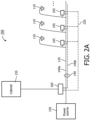
- FIG 2A illustrates an exemplary network configuration 200.
- the luminaries 110 are connected through the power grid 120 (for delivering energy to the luminaires), as previously discussed, and operate as discussed with regard to Figure 1 .
- the primary communication network 140 is represented as being comparable to the power grid 120, wherein control signals are provided over the physical lines of power grid 120.
- an alternative (secondary) network 220 provides an alternative path for communication to each of the luminaries 110.
- the alternative network 220 is a wired network that operates independent of the power grid 120 and the primary communication network 140.
- the wire-ed alternative network 220 may be a dedicated network that provides control signals to each luminaire 110.
- control signals are provided from a cabinet 155, through interface 160, to both the primary communication network 140 and the alternative network 220.
- Interface 160 may provide control signals to each network 140 and 220, individually or in combination.
- the interface device 165 corresponding to the luminaries 110, monitors both networks (140 and 220) to determine whether control signals are present on either network 140 or 220 to control the operation of the corresponding luminaire 110.
- the wired alternative communication network 220 may be one of a public network (e.g., internet) or a private network.
- interface device 165 is illustrated located on corresponding luminaires 110, it would be recognized that interface device 165 may be located at corresponding luminaries (i.e., integrated with the luminary electronic circuitry) or may be located in cabinet (segment controller) 155. Hence, interface device 165 may be integrated/non-integrated with the luminaire or integrated/non-integrated with the communication module 160 or integrated/non-integrated with the cabinet 155. The exact placement of interface device 165 is not material.
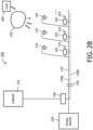
- FIG. 2B illustrates another exemplary network configuration 250 in accordance with the principles of the invention.
- the luminaries 110 are connected through the power grid 120 (to supply power to the luminaires) and primary communication network 140, as previously discussed, and operate as discussed with regard to Figure 1 .
- alternative network 270 provides an alternative communication and control path.
- the alternative network 270 may be a wireless network that operates independent of the power grid 120 and primary communication network 140.
- the wireless alternative network 270 may be a dedicated network or a public network that provides control signals to each luminaire 110 and may operate using one or more well-known communication protocols (e.g., IEEE 802.15.4, WIFI, Cellphones technology, 2G, 3G. 4G, etc.).
- interface 165 includes a receiving system 275 that receives signals transmitted over the wireless network 270. Interface 165 then operates on control signals (information) received from either the primary communication network 140 or the alternative wireless network 270.
- the control signals may be provided to the wireless network 270 by a demand access device 260.
- the demand access device 260 may provide control signals in case a fault is determined to exist in the primary network 140 or when a lighting condition is desired that is not provided by the electronic cabinet 155 at the desired time or place.
- the demand access device may be one of a special purpose device that operates with a dedicated communication protocol, or may be a general purpose device (e.g., a cellular telephone) that operates using well-known publicly available protocols.
- the general purpose device may transmit messages that identify one or more luminaries 110 to operate in a desired fashion (e.g., lighting level).
- the luminaries 110 may be individually identified as network elements using well-known identification methods and respond to commands provided through the auxiliary network(s) (220, 270).
- the identification of the luminaries with regard to the auxiliary network(s) 220, 270 may or may not be the same as the identification of the luminaries 110 with regard to the primary communication network.
- interface device 165 monitors both the primary network 140 and the auxiliary network 270 to determine whether control signals are present on either network (140, 270) to control the operation of the corresponding luminaire 110.
- the receiving system 275 included in the interface 165 of the corresponding luminaire 110, is of a low energy consumption type that may be integrated into the existing interface device 165 or may be separated from the interface device 165.
- the receiving system 275 may be powered by the existing luminaire power grid (i.e., mains) 120 or other means (e.g., solar cells).
- wireless alternative communication network 270 may be a local area network (LAN) or a wide area network (WAN) that may be public or private.
- LAN local area network
- WAN wide area network
- the interface device165 may operate such that a detection of a change in a known voltage range (e.g., 0-10 volts) may be used to determine a dimming level. For example, detecting a control signal of magnitude 5 volts implies a dimming level of fifty (50) per-cent, while a control signal of 10 volts represents a full turn on.
- the interface device 165 may then provide an appropriate change in lighting command to the corresponding luminaire to produce the desired lighting effect.
- the light level of a corresponding luminary may be set from a minimum to a maximum light level dependent upon a sensed voltage level or change in voltage level.
- the receiving system may include a DALI (Digital Addressable Lighting Interface) interface that receives a specific dimming control command and provides the command to a luminaire driving circuitry.
- the luminaire driving circuitry may execute an application (or a logical set of instructions) in response to the received command.
- DALI Digital Addressable Lighting Interface
- the luminaire driving circuitry may execute an application (or a logical set of instructions) in response to the received command.
- DALI is a well-known interface that need not be discussed in detail herein. DALI interfaces may be used in indoor lighting system networks.
- the receiving system may determine changes in modulation and/or signal type to control operation of the luminaries 110. For example, if Pulse Width Modulation (PWM) coded signals are used as control signals, then changes in the signal pulse width, for example, may cause different levels of dimming or element control to occur.
- PWM Pulse Width Modulation
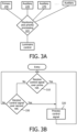
- FIG 3A illustrates an exemplary representation of the processing for managing elements of a network in accordance with the principles of the invention.
- interface device 165 corresponding to each of the luminaries (light fixtures, network elements) monitors one or more communication networks; in this case a primary network 140 and at least one auxiliary network (270).
- the primary communication network is similar to network 140 and the auxiliary networks are similar to networks 270, previously discussed.
- interface 165 may include software and hardware elements that provide for detecting commands on one or more communication networks that may operate on different medium (e.g., wired, wireless) and different protocols (e.g., IEEE 802.11).
- processing within interface device 165 determines a priority of the received commands from the corresponding networks and initiates a decision process regarding the received command.
- an output is transmitted to the corresponding network element (luminaire) to operate the luminaire in conformance with the received command.
- Priority settings in interface device 165 may be set by the user depending on the user's desired lighting requirements. For example, a user may set priorities such that a command from an auxiliary network has a higher priority than a command received from the primary network. Thus, when commands are received concurrently over the primary and an auxiliary network, interface device 165 may operate to execute the command associated with the auxiliary network over the command received from the primary network. Similarly, the priority settings may be such that the command received from an auxiliary network may be maintained for at least a predetermined period of time. In this case, a command received from a primary network (based on time, for example) may be ignored if received within the predetermined period of time after a command received from the auxiliary network.
- FIG. 3B illustrates an exemplary process for managing elements of a network in accordance with the principles of the invention.
- an electronic interface device 165 associated with a corresponding network element e.g., luminaire
- the command may be a signal provided over the primary communication network at block 310.
- the command may be determined by monitoring a signal line of the primary communication network 140 for the presence of a signal, a change in a status of an existing signal or by the generation of an interrupt that causes the electronic interface device 165 to determine that a change in the status of a signal line has occurred.
- the electronic interface device 165 executes an application that operates to control a change the status of the luminaire (e.g., turn on, turn off, dim, etc.) according to the detected signal (or change in the signal) at block 320.
- a change the status of the luminaire e.g., turn on, turn off, dim, etc.
- the electronic interface device 165 determines whether a command (i.e., a signal or a change in signal) has been received over an alternative (secondary) network.
- a command i.e., a signal or a change in signal
- This command may be determined by monitoring a signal line for a presence of a signal, a change in a status of an existing signal or by the generation of an interrupt that causes the electronic control device to process a change in the status of a signal line.
- the electronic interface device165 executes an application (or causes the execution of an application) that operates to alter the status of the network element (e.g., luminaire), appropriately (e.g., turn on, turn off, dim, etc.) at block 340.
- an application or causes the execution of an application that operates to alter the status of the network element (e.g., luminaire), appropriately (e.g., turn on, turn off, dim, etc.) at block 340.
- Processing then proceeds to block 310 to continue monitoring the primary network.
- FIG. 4 illustrates a second exemplary embodiment of processing 400 in accordance with the principles of the invention.
- a determination is made at block 410 whether a command has been received from the primary network. If a command has been received, then a determination is made whether the command from the primary network has been received within a predetermined time from a previous command received on an auxiliary network at block 420. If the command received on the primary network has been received within a predetermined time from the last command received from an auxiliary command, then a determination is made whether a command has been received on an auxiliary network at block 430. If no command from an auxiliary has been received, then the primary command is ignored at block 440. However, if a command from an auxiliary network has been received at block 430, then processing of the auxiliary command is performed at block 480 and the time of receiving the command from the auxiliary network is stored at block 490.
- the predetermined time may be set by the user during the priority settings or may be set according to the type of command received on the auxiliary network.
- the above-described methods according to the present invention can be implemented in hardware, firmware or as software or computer code that can be stored in a recording medium such as a CD ROM, an RAM, a floppy disk, a hard disk, or a magnetooptical disk or computer code downloaded over a network originally stored on a remote recording medium or a non-transitory machine readable medium and to be stored on a local recording medium, so that the methods described herein can be rendered in such software that is stored on the recording medium using a general purpose computer(s), or a special processor(s) or in programmable or dedicated hardware(s), such as an ASIC or FPGA.
- a recording medium such as a CD ROM, an RAM, a floppy disk, a hard disk, or a magnetooptical disk or computer code downloaded over a network originally stored on a remote recording medium or a non-transitory machine readable medium and to be stored on a local recording medium, so that the methods described herein can be rendered in such software that is stored on the
- the computer(s), the processor(s), microprocessor controller(s) or the programmable hardware(s) include memory components, e.g., RAM, ROM, Flash, etc. that may store or receive software or computer code that when accessed and executed by the computer(s), processor(s) or hardware(s) implement the processing methods described herein.
- memory components e.g., RAM, ROM, Flash, etc.
- the execution of the code transforms the general purpose computer(s) into a special purpose computer(s) for executing the processing shown herein.
Landscapes
- Engineering & Computer Science (AREA)
- Computer Networks & Wireless Communication (AREA)
- General Engineering & Computer Science (AREA)
- Physics & Mathematics (AREA)
- General Physics & Mathematics (AREA)
- Automation & Control Theory (AREA)
- Circuit Arrangement For Electric Light Sources In General (AREA)
- Selective Calling Equipment (AREA)
Description
- This application is related to the field of lighting network management systems, and more particularly to a method and device to provide reliable communications with lighting network systems.
- Lighting is usually managed from one centralized point that can be referred to as a central management system. A challenging question is to define "Central Management System" (CMS) in the context of a lighting installation (outdoor and/or indoor lighting networks). Perhaps a CMS is best characterized as a communication system for providing 'Monitoring', 'Reporting' and 'Control' of lighting (e.g., street lighting and/or indoor lighting). The exact hardware and software required to implement a CMS varies between the different approaches adopted by the various manufacturers producing CMS today.
- Currently, several ways for communicating and controlling outdoor and indoor luminaires are available. Networks for communication and control may be wired or wireless. For example, power line and RF communication systems are methods for controlling luminaires in a network. For example, the Starsense system, manufactured by the assignee of the instant application, is a telemanagement system with remote control of outdoor light points (elements) on highways, roads, streets, and in residential areas. The Starsense products save energy by enabling individual light points to be switched on or off at any given time or set to any dimming level. Although, the Starsense system is here used as an example of an outdoor lighting system, it would be recognized by those skilled in the art that the invention disclosed herein is also applicable to other types of outdoor and indoor lighting systems with wired or wireless communication and control paths for lighting system behavior management.
- United States patent application
US 2011/140611 A1 discloses a lighting control system coupled to one or more ballast/drivers operating one or more light sources. A low power control module receives analog, digital and/or DALI signals from one of more sources, processes the signals to provide an appropriate lighting response and outputs one or more commands related to light output of the one or more ballast/drivers operating one or more light sources. - United States patent application
US 2009/0309512 A1 relates to a mechanism for prioritizaiton of DALI signals entering from to separate buses or inputs, wherein upon receipt of signals arriving via the two inputs, the mechanism allocates priorities to the signals on the basis of predetermined criteria, to this end it proposes to temporarily store signals so as to allow evaluation of their priorities and then forward the command having priority to at least one electronic ballast, which in turn processes the control signals further and delivers output sights for a light. - However, central management of outdoor (or indoor) luminaries over a primary network may, in certain situations, be impractical (e.g., disrupted, blocked, non-functional, etc.) as local conditions may require different (easier, back-up...) settings.
- In addition, local control of the luminaries may be required to satisfy certain imposed requirements. For example, local control may be implemented with a demand response (DR) operation. Demand response operations can be defined as a set of initiatives that allows electric energy customers to change their electricity usage for a certain period of time due to receiving a price signal from the utility.
- In addition, communication with, and control of, luminaires in an outdoor or an indoor system, may be interrupted when a primary communication and control path is not available or not applicable at certain periods.
- Hence there is a need for an alternative communication / control path (for the utilities) to the luminaire or to other system components or systems, e.g., police, fire, traffic management, etc., to provide control of the devices in the systems when the primary communication path is not functional. In addition, the alternative communication/ control path may enable subsidies and incentives, increase energy savings, and meet different set / agreed / needed / enforced targets.
- In view of the above, the present disclosure is directed to methods for controlling a luminaire of an illumination network and devices for controlling a luminaire in an illumination network comprising a plurality of luminaires. The invention is set out in the appended set of claims.
- In one aspect of the invention, a method for controlling an element of a network is disclosed. The method comprises monitoring a primary communication network; monitoring an alternative communication network; receiving a command from the primary communication network and another command from the alternative communication network; prioritizing the received commands using a priority setting; and executing an application in response to the prioritized received command, said application controlling the operation of the luminaire and wherein the primary communication network and the alternative communication network are independent the method characterized in that: the primary communication network is either a wired network or wireless network and the alternative communication network is a wireless network and the priority setting involves a setting whereby a first command from the alternative communication network is maintained for at least a predetermined period of time and second commands received from the primary communication network are ignored if received within the predetermined period of time after the first command was received from the alternative communication network.
- Alternatively, the primary communication network is a wireless network and the alternative communication network is a wired network
- In another aspect of the invention, a device for controlling an element of a network comprising a plurality of luminaires is disclosed. The device comprising:
at least one processor in communication with a memory, the memory including code which when accessed by the at least one processor, causes the at least one processor to: monitor a primary communication network; monitor an alternative communication network; receive a command from the primary communication network and another command from the alternative communication network; prioritize the received commands using a priority setting; and execute an application in response to the prioritized received command, said application controlling the operation of the luminaire and wherein the primary communication network and the alternative communication network are independent the device characterized in that: the primary communication network is either a wired network or wireless network and the alternative communication network is a wireless network and the priority setting involves a setting whereby a first command from the alternative communication network is maintained for at least a predetermined period of time and second commands received from the primary communication network are ignored if received within the predetermined period of time after the first command was received from the alternative communication network. - Alternatively, the primary communication network is a wireless network and the alternative communication network is a wired network
- The advantages, nature, and various additional features of the invention will appear more fully upon consideration of the accompanying drawings wherein like reference numerals are used to identify like element throughout the drawings:
-
Figure 1 represents an exemplary illumination system configuration; -
Figure 2A represents an exemplary illumination system configuration; -
Figure 2B represents another exemplary illumination system configuration in accordance with the principles of the invention; -
Figure 3A represents an exemplary implementation for providing control of the luminaries in an illumination system in accordance with the principles of the invention; -
Figure 3B represents an exemplary method for providing control of the luminaries in an illumination system in accordance with the principles of the invention; and -
Figure 4 represents a second exemplary method for providing control of the luminaries in an illumination system in accordance with the principles of the invention. - It is to be understood that the figures and descriptions of the present invention described herein have been simplified to illustrate the elements that are relevant for a clear understanding of the present invention, while eliminating, for purposes of clarity many other elements. However, because these elements are well-known in the art, and because they do not facilitate a better understanding of the present invention, a discussion of such element is not provided herein. The disclosure herein is directed to also variations and modifications known to those skilled in the art.
- For the sake of clarity, methods and devices wherein both the primary communication network and the alternative communication network are implemented as a wired network are outside the scope of the claimed invention.
-
Figure 1 represents an exemplary illumination system100 including a plurality of outdoor luminaries, 110, wherein each of the illustratedluminaries 110 is connected through a power grid (network) 120. In the exemplary power grid (network) 120 shown, theluminaries 110 are connected in a serial manner.Figure 1 is one example how an outdoor lighting network can be connected, controlled and/or communicated with the luminaries 110 (network elements) through apower grid 120 that supplies power to theluminaries 110 frompower source 150. In addition, aprimary communication network 140 provides control signals to each of the illustratedluminaries 110. In the configuration illustrated inFigure 1 , theprimary communication network 140 may be incorporated into thepower grid 120, wherein thelines 140a represent the power lines that provide power to theluminaries 110 and thelines 140b represent the (same) power lines that provide control signals to theluminaries 110. It would be recognized thatlines power grid 120 upon which both power and control (information) are implemented. The control (or information) signals may be used to turn theluminaries 110 on or off or to dim the luminaires to conserve power. Providing communication and/or control (or information) signals over apower line network 120 is well known in the art and need not be discussed in detail herein. - In other systems, the
primary communication network 140 may be totally independent of thepower grid 120 and may be a wired or a wireless system. For example, a wire-edprimary communication network 140 may be one of a public network (e.g., internet) or a private network. Similarly, a wirelessprimary communication network 140 may be a local area network (LAN) or a wide area network (WAN) than may be public or private. In each case, theluminaries 110 include components that accept the communication provided through theprimary communication network 140. - In controlling the luminaries, an electronic cabinet (or a segment controller that is not in the cabinet form) 155 may provide control signals (or information) over the primary communication network 140 (which may or may not be the same as the power grid 120) to each
luminaire 110. Eachluminaire 110 may include anelectronic interface device 165 that monitors the signals transmitted overprimary communication network 140. When command signals are detected on theprimary communication network 140, theelectronic interface device 165 provides the appropriate signals to alter the state of thecorresponding luminaire 110. -
Figure 2A illustrates anexemplary network configuration 200. In this exemplary network, theluminaries 110 are connected through the power grid 120 (for delivering energy to the luminaires), as previously discussed, and operate as discussed with regard toFigure 1 . In addition, theprimary communication network 140 is represented as being comparable to thepower grid 120, wherein control signals are provided over the physical lines ofpower grid 120. In addition, an alternative (secondary)network 220 provides an alternative path for communication to each of theluminaries 110. - In the illustrated example, the
alternative network 220 is a wired network that operates independent of thepower grid 120 and theprimary communication network 140. - The wire-ed
alternative network 220, illustrated, may be a dedicated network that provides control signals to eachluminaire 110. In the illustrated network configuration, control signals are provided from acabinet 155, throughinterface 160, to both theprimary communication network 140 and thealternative network 220.Interface 160 may provide control signals to eachnetwork interface device 165, corresponding to theluminaries 110, monitors both networks (140 and 220) to determine whether control signals are present on eithernetwork corresponding luminaire 110. The wiredalternative communication network 220 may be one of a public network (e.g., internet) or a private network. Althoughinterface device 165 is illustrated located on correspondingluminaires 110, it would be recognized thatinterface device 165 may be located at corresponding luminaries (i.e., integrated with the luminary electronic circuitry) or may be located in cabinet (segment controller) 155. Hence,interface device 165 may be integrated/non-integrated with the luminaire or integrated/non-integrated with thecommunication module 160 or integrated/non-integrated with thecabinet 155. The exact placement ofinterface device 165 is not material. -
Figure 2B illustrates anotherexemplary network configuration 250 in accordance with the principles of the invention. In this exemplary network, theluminaries 110 are connected through the power grid 120 (to supply power to the luminaires) andprimary communication network 140, as previously discussed, and operate as discussed with regard toFigure 1 . In addition,alternative network 270 provides an alternative communication and control path. - In the illustrated example, the
alternative network 270 may be a wireless network that operates independent of thepower grid 120 andprimary communication network 140. The wirelessalternative network 270 may be a dedicated network or a public network that provides control signals to eachluminaire 110 and may operate using one or more well-known communication protocols (e.g., IEEE 802.15.4, WIFI, Cellphones technology, 2G, 3G. 4G, etc.). - In this illustrative example,
interface 165 includes a receivingsystem 275 that receives signals transmitted over thewireless network 270.Interface 165 then operates on control signals (information) received from either theprimary communication network 140 or thealternative wireless network 270. The control signals may be provided to thewireless network 270 by ademand access device 260. Thedemand access device 260 may provide control signals in case a fault is determined to exist in theprimary network 140 or when a lighting condition is desired that is not provided by theelectronic cabinet 155 at the desired time or place. The demand access device may be one of a special purpose device that operates with a dedicated communication protocol, or may be a general purpose device (e.g., a cellular telephone) that operates using well-known publicly available protocols. For example, the general purpose device may transmit messages that identify one ormore luminaries 110 to operate in a desired fashion (e.g., lighting level). - As would be appreciated, the
luminaries 110 may be individually identified as network elements using well-known identification methods and respond to commands provided through the auxiliary network(s) (220, 270). The identification of the luminaries with regard to the auxiliary network(s) 220, 270, may or may not be the same as the identification of theluminaries 110 with regard to the primary communication network. - In this illustrated example shown in
Figure 2B ,interface device 165 monitors both theprimary network 140 and theauxiliary network 270 to determine whether control signals are present on either network (140, 270) to control the operation of thecorresponding luminaire 110. - In one aspect of the invention, the receiving
system 275, included in theinterface 165 of thecorresponding luminaire 110, is of a low energy consumption type that may be integrated into the existinginterface device 165 or may be separated from theinterface device 165. As the receivingsystem 275 is of a low energy consumption type, the receivingsystem 275 may be powered by the existing luminaire power grid (i.e., mains) 120 or other means (e.g., solar cells). - In one aspect of the invention, wireless
alternative communication network 270 may be a local area network (LAN) or a wide area network (WAN) that may be public or private. - In one aspect of the invention, the interface device165 may operate such that a detection of a change in a known voltage range (e.g., 0-10 volts) may be used to determine a dimming level. For example, detecting a control signal of magnitude 5 volts implies a dimming level of fifty (50) per-cent, while a control signal of 10 volts represents a full turn on. The
interface device 165 may then provide an appropriate change in lighting command to the corresponding luminaire to produce the desired lighting effect. Thus, the light level of a corresponding luminary may be set from a minimum to a maximum light level dependent upon a sensed voltage level or change in voltage level. - In another aspect of the invention, the receiving system may include a DALI (Digital Addressable Lighting Interface) interface that receives a specific dimming control command and provides the command to a luminaire driving circuitry. The luminaire driving circuitry may execute an application (or a logical set of instructions) in response to the received command. DALI is a well-known interface that need not be discussed in detail herein. DALI interfaces may be used in indoor lighting system networks.
- In another aspect of the invention, the receiving system may determine changes in modulation and/or signal type to control operation of the
luminaries 110. For example, if Pulse Width Modulation (PWM) coded signals are used as control signals, then changes in the signal pulse width, for example, may cause different levels of dimming or element control to occur. -
Figure 3A illustrates an exemplary representation of the processing for managing elements of a network in accordance with the principles of the invention. In this exemplary processing,interface device 165, corresponding to each of the luminaries (light fixtures, network elements) monitors one or more communication networks; in this case aprimary network 140 and at least one auxiliary network (270). The primary communication network is similar tonetwork 140 and the auxiliary networks are similar tonetworks 270, previously discussed. As would be appreciated by those skilled in the art,interface 165 may include software and hardware elements that provide for detecting commands on one or more communication networks that may operate on different medium (e.g., wired, wireless) and different protocols (e.g., IEEE 802.11). - Upon receiving a command from at least one of the networks, then processing within
interface device 165 determines a priority of the received commands from the corresponding networks and initiates a decision process regarding the received command. - After the priority processing associated with the received command is processed, an output is transmitted to the corresponding network element (luminaire) to operate the luminaire in conformance with the received command.
- Priority settings in
interface device 165 may be set by the user depending on the user's desired lighting requirements. For example, a user may set priorities such that a command from an auxiliary network has a higher priority than a command received from the primary network. Thus, when commands are received concurrently over the primary and an auxiliary network,interface device 165 may operate to execute the command associated with the auxiliary network over the command received from the primary network. Similarly, the priority settings may be such that the command received from an auxiliary network may be maintained for at least a predetermined period of time. In this case, a command received from a primary network (based on time, for example) may be ignored if received within the predetermined period of time after a command received from the auxiliary network. -
Figure 3B illustrates an exemplary process for managing elements of a network in accordance with the principles of the invention. In this exemplary process, anelectronic interface device 165 associated with a corresponding network element (e.g., luminaire) monitors theprimary communication network 140 to determine whether a command has been received. The command may be a signal provided over the primary communication network atblock 310. The command may be determined by monitoring a signal line of theprimary communication network 140 for the presence of a signal, a change in a status of an existing signal or by the generation of an interrupt that causes theelectronic interface device 165 to determine that a change in the status of a signal line has occurred. In response to the detected command (signal or change in the signal), theelectronic interface device 165 executes an application that operates to control a change the status of the luminaire (e.g., turn on, turn off, dim, etc.) according to the detected signal (or change in the signal) atblock 320. - However, if no command is detected to exist on the primary communication network, then at
block 330, theelectronic interface device 165 determines whether a command (i.e., a signal or a change in signal) has been received over an alternative (secondary) network. This command may be determined by monitoring a signal line for a presence of a signal, a change in a status of an existing signal or by the generation of an interrupt that causes the electronic control device to process a change in the status of a signal line. In response to the detected command (i.e., signal or change in signal status), the electronic interface device165 executes an application (or causes the execution of an application) that operates to alter the status of the network element (e.g., luminaire), appropriately (e.g., turn on, turn off, dim, etc.) at block 340. - Processing then proceeds to block 310 to continue monitoring the primary network.
-
Figure 4 illustrates a second exemplary embodiment of processing 400 in accordance with the principles of the invention. In this exemplary embodiment, a determination is made atblock 410 whether a command has been received from the primary network. If a command has been received, then a determination is made whether the command from the primary network has been received within a predetermined time from a previous command received on an auxiliary network atblock 420. If the command received on the primary network has been received within a predetermined time from the last command received from an auxiliary command, then a determination is made whether a command has been received on an auxiliary network atblock 430. If no command from an auxiliary has been received, then the primary command is ignored atblock 440. However, if a command from an auxiliary network has been received atblock 430, then processing of the auxiliary command is performed atblock 480 and the time of receiving the command from the auxiliary network is stored atblock 490. - Returning to block 420, if the command from the primary network is determined to be received at a time greater than the predetermined time from the last auxiliary command then a determination is made whether a command from an auxiliary network has also been received. If a command from the auxiliary device has not been received, then the command from the primary network is processed at
block 460. However, if a command from an auxiliary network has been received, then processing of the command from the auxiliary network is performed atblock 480, as previously described. - Returning to block 410, if a command on the primary network has not been received, a determination is made whether a command has been received over an auxiliary network at
block 470. If a command from an auxiliary network has not been received, the processing exits. However, if a command from an auxiliary network has been received, then processing of the auxiliary network command is performed atblock 480. - As would be appreciated, the predetermined time may be set by the user during the priority settings or may be set according to the type of command received on the auxiliary network.
- The above-described methods according to the present invention can be implemented in hardware, firmware or as software or computer code that can be stored in a recording medium such as a CD ROM, an RAM, a floppy disk, a hard disk, or a magnetooptical disk or computer code downloaded over a network originally stored on a remote recording medium or a non-transitory machine readable medium and to be stored on a local recording medium, so that the methods described herein can be rendered in such software that is stored on the recording medium using a general purpose computer(s), or a special processor(s) or in programmable or dedicated hardware(s), such as an ASIC or FPGA. As would be understood in the art, the computer(s), the processor(s), microprocessor controller(s) or the programmable hardware(s) include memory components, e.g., RAM, ROM, Flash, etc. that may store or receive software or computer code that when accessed and executed by the computer(s), processor(s) or hardware(s) implement the processing methods described herein. In addition, it would be recognized that when a general purpose computer(s) accesses code for implementing the processing shown herein, the execution of the code transforms the general purpose computer(s) into a special purpose computer(s) for executing the processing shown herein.
Claims (9)
- A method for controlling a luminaire (110) of an illumination network comprising a plurality of luminaries, said method comprising:monitoring a primary communication network (140);monitoring an alternative communication network (220, 270);receiving a command from the primary communication network and another command from the alternative communication network;
prioritizing the received commands using a priority setting; andexecuting an application in response to the prioritized received command, said application controlling the operation of the luminaire (110) andwherein the primary communication network (140) and the alternative communication network (220, 270) are independentthe method characterized in that:the primary communication network is either a wired network or wireless network and the alternative communication network is a wireless network andthe priority setting involves a setting whereby a first command from the alternative communication network (220, 270) is maintained for at least a predetermined period of time and second commands received from the primary communication network (140) are ignored if received within the predetermined period of time after the first command was received from the alternative communication network. - A method for controlling a luminaire (110) of an illumination network comprising a plurality of luminaries, said method comprising:monitoring a primary communication network (140);monitoring an alternative communication network (220, 270);receiving a command from the primary communication network and another command from the alternative communication network;
prioritizing the received commands using a priority setting; andexecuting an application in response to the prioritized received command, said application controlling the operation of the luminaire (110) andwherein the primary communication network (140) and the alternative communication network (220, 270) are independentthe method characterized in that:the primary communication network is a wireless network and the alternative communication network is either a wired network andthe priority setting involves a setting whereby a first command from the alternative communication network (220, 270) is maintained for at least a predetermined period of time and second commands received from the primary communication network (140) are ignored if received within the predetermined period of time after the first command was received from the alternative communication network. - The method according to claim 1 or 2, further comprising;
providing power to the luminaire of the illumination network through a power network (120). - The method according to claim 1, wherein the primary communication network (140) is incorporated into said power network (120).
- The method according to claim 1 or 2, wherein the predetermined period of time is set:- by a user during a priority setting or- according to the type of command received on the auxiliary network.
- A device (165) for controlling a luminaire (110) of an illumination network comprising a plurality of luminaires, said device comprising:at least one processor in communication with a memory, the memory including code which when accessed by the at least one processor, causes the at least one processor to:the device characterized in that:monitor a primary communication network (140);monitor an alternative communication network (220, 270);receive a command from the primary communication network and another command from the alternative communication network;
prioritize the received commands using a priority setting; andexecute an application in response to the prioritized received command, said application controlling the operation of the luminaire (110) andwherein the primary communication network and the alternative communication network are independentt he primary communication network is either a wired network or wireless network and the alternative communication network is a wireless network andt he priority setting involves a setting whereby a first command from the alternative communication network (220, 270) is maintained for at least a predetermined period of time and second commands received from the primary communication network (140) are ignored if received within the predetermined period of time after the first command was received from the alternative communication network. - A device (165) for controlling a luminaire (110) of an illumination network comprising a plurality of luminaires, said device comprising:at least one processor in communication with a memory, the memory including code which when accessed by the at least one processor, causes the at least one processor to:the device characterized in that:monitor a primary communication network (140);monitor an alternative communication network (220, 270);receive a command from the primary communication network and another command from the alternative communication network;
prioritize the received commands using a priority setting; andexecute an application in response to the prioritized received command, said application controlling the operation of the luminaire (110) andwherein the primary communication network and the alternative communication network are independentt he primary communication network is a wireless network and the alternative communication network is wired network andt he priority setting involves a setting whereby a first command from the alternative communication network (220, 270) is maintained for at least a predetermined period of time and second commands received from the primary communication network (140) are ignored if received within the predetermined period of time after the first command was received from the alternative communication network. - The device (165) of claim 6 or 7, wherein said illumination network is one of: an outdoor lighting system and an indoor lighting system.
- The device (165) according to claim 6 or 7, wherein the predetermined period of time is set:- by a user during a priority setting or- according to the type of command received on the auxiliary network.
Applications Claiming Priority (3)
| Application Number | Priority Date | Filing Date | Title |
|---|---|---|---|
| US201261669891P | 2012-07-10 | 2012-07-10 | |
| PCT/IB2013/055630 WO2014009880A2 (en) | 2012-07-10 | 2013-07-09 | System and method for providing alternative communication path for management of lighting network elements |
| EP13766683.0A EP2873302B1 (en) | 2012-07-10 | 2013-07-09 | System and method for providing alternative communication path for management of lighting network elements |
Related Parent Applications (2)
| Application Number | Title | Priority Date | Filing Date |
|---|---|---|---|
| EP13766683.0A Division EP2873302B1 (en) | 2012-07-10 | 2013-07-09 | System and method for providing alternative communication path for management of lighting network elements |
| EP13766683.0A Division-Into EP2873302B1 (en) | 2012-07-10 | 2013-07-09 | System and method for providing alternative communication path for management of lighting network elements |
Publications (2)
| Publication Number | Publication Date |
|---|---|
| EP3840538A1 EP3840538A1 (en) | 2021-06-23 |
| EP3840538B1 true EP3840538B1 (en) | 2023-10-18 |
Family
ID=49237537
Family Applications (2)
| Application Number | Title | Priority Date | Filing Date |
|---|---|---|---|
| EP21150944.3A Active EP3840538B1 (en) | 2012-07-10 | 2013-07-09 | System and method for providing alternative communication path for management of lighting network elements |
| EP13766683.0A Active EP2873302B1 (en) | 2012-07-10 | 2013-07-09 | System and method for providing alternative communication path for management of lighting network elements |
Family Applications After (1)
| Application Number | Title | Priority Date | Filing Date |
|---|---|---|---|
| EP13766683.0A Active EP2873302B1 (en) | 2012-07-10 | 2013-07-09 | System and method for providing alternative communication path for management of lighting network elements |
Country Status (7)
| Country | Link |
|---|---|
| US (1) | US9398668B2 (en) |
| EP (2) | EP3840538B1 (en) |
| JP (1) | JP6263176B2 (en) |
| CN (1) | CN104412715B (en) |
| BR (1) | BR112015000325B1 (en) |
| RU (1) | RU2635379C2 (en) |
| WO (1) | WO2014009880A2 (en) |
Families Citing this family (13)
| Publication number | Priority date | Publication date | Assignee | Title |
|---|---|---|---|---|
| US10262527B2 (en) | 2014-03-21 | 2019-04-16 | Signify Holding B.V. | Commissioning of remotely managed intelligent lighting devices |
| WO2016016838A1 (en) * | 2014-07-31 | 2016-02-04 | Enel Sole S.R.L. | Outdoor lighting apparatus with short range of very short range communication interface |
| PE20170616A1 (en) | 2014-07-31 | 2017-05-30 | Enel Sole Srl | OUTDOOR LIGHTING APPARATUS FOR FIXED INSTALLATION WITH CONTROL AND COMMUNICATION CIRCUIT |
| FI125800B (en) * | 2014-10-21 | 2016-02-29 | Univ Aalto Foundation | Procedure and system for controlling a lighting network |
| WO2016173921A1 (en) | 2015-04-30 | 2016-11-03 | Philips Lighting Holding B.V. | Upgrading a light source |
| GB2542806B (en) | 2015-09-30 | 2021-07-21 | Tridonic Gmbh & Co Kg | Lighting state synchronization |
| JP6575871B2 (en) * | 2016-01-15 | 2019-09-18 | パナソニックIpマネジメント株式会社 | Lighting equipment and lighting system |
| EP3408976B1 (en) * | 2016-01-29 | 2019-12-11 | Signify Holding B.V. | Managing network traffic in application control networks |
| US10477650B2 (en) * | 2017-03-06 | 2019-11-12 | Usai, Llc | Digital lighting control method and system |
| CN107277992A (en) * | 2017-06-28 | 2017-10-20 | 芜湖远博电子科技有限公司 | It is a kind of that method is regulated and controled based on the intelligent lamp that indoor and outdoor light luminance is analyzed |
| CN107277993A (en) * | 2017-06-28 | 2017-10-20 | 芜湖远博电子科技有限公司 | A kind of intelligent lamp system detected based on light luminance |
| CN108391353A (en) * | 2018-04-20 | 2018-08-10 | 广州供电局有限公司 | Wisdom illumination monitoring method, apparatus, terminal and system |
| IT201900018671A1 (en) * | 2019-10-14 | 2021-04-14 | Areti S P A | SYSTEM AND METHOD OF COMMUNICATION AND DATA MANAGEMENT BASED ON A PUBLIC LIGHTING NETWORK |
Family Cites Families (22)
| Publication number | Priority date | Publication date | Assignee | Title |
|---|---|---|---|---|
| US4412285A (en) * | 1981-04-01 | 1983-10-25 | Teradata Corporation | Multiprocessor intercommunication system and method |
| US5905442A (en) * | 1996-02-07 | 1999-05-18 | Lutron Electronics Co., Inc. | Method and apparatus for controlling and determining the status of electrical devices from remote locations |
| JP2003068475A (en) * | 2001-08-28 | 2003-03-07 | Matsushita Electric Works Ltd | Illumination control system |
| AU2003216397A1 (en) * | 2002-02-25 | 2003-09-09 | General Electric Company | Electrical protection system for reliability improvement based on sensitivity analysis |
| CN2638389Y (en) | 2003-07-29 | 2004-09-01 | 廖明振 | Instant strain system for road signal lamp falture |
| DE10344619B4 (en) | 2003-09-25 | 2018-07-12 | Zumtobel Lighting Gmbh | Control system for a plurality of distributed lamp operating devices and method for initializing such a control system |
| JP2005129365A (en) * | 2003-10-24 | 2005-05-19 | Matsushita Electric Works Ltd | Lighting control system |
| WO2006023841A2 (en) | 2004-08-18 | 2006-03-02 | California Institute Of Technology | Roadside-based communication system and method |
| JP2008514096A (en) * | 2004-09-22 | 2008-05-01 | コーニンクレッカ フィリップス エレクトロニクス エヌ ヴィ | Wired and wireless lighting devices |
| US7911359B2 (en) | 2005-09-12 | 2011-03-22 | Abl Ip Holding Llc | Light management system having networked intelligent luminaire managers that support third-party applications |
| JP4980108B2 (en) * | 2006-03-22 | 2012-07-18 | 東芝ライテック株式会社 | Lighting control device |
| US7748878B2 (en) * | 2006-05-18 | 2010-07-06 | Production Resource Group, Inc. | Lighting control system with wireless network connection |
| DE102006033673A1 (en) * | 2006-07-20 | 2008-01-24 | Patent-Treuhand-Gesellschaft für elektrische Glühlampen mbH | Switchgear, system for controlling a lamp and lighting control system for a building with at least one luminaire |
| JP4219950B2 (en) * | 2006-10-16 | 2009-02-04 | シャープ株式会社 | COMMUNICATION DEVICE, COMMUNICATION METHOD, COMMUNICATION CIRCUIT, MOBILE PHONE, PROGRAM, AND COMPUTER-READABLE RECORDING MEDIUM CONTAINING THE PROGRAM |
| CN101336024A (en) * | 2007-06-29 | 2008-12-31 | 上海国皓电子有限公司 | Centralized control type light modulating apparatus for scene lighting |
| CN101389172B (en) | 2007-09-12 | 2011-12-21 | 浙江晶日照明科技有限公司 | Road lamp wireless detection control system |
| CN102017803A (en) | 2008-02-22 | 2011-04-13 | 三杰科技有限公司 | Apparatus and system for LED street lamp monitoring and control |
| US8212485B2 (en) | 2009-12-10 | 2012-07-03 | General Electric Company | Dimming bridge module |
| JP2011155589A (en) * | 2010-01-28 | 2011-08-11 | Hitachi Ltd | Hybrid communication terminal, and program |
| US20110215732A1 (en) | 2010-03-04 | 2011-09-08 | Wen-Lin Chen | Built-in lamp wireless dimmer device |
| CN201878386U (en) | 2010-11-17 | 2011-06-22 | 无锡科依德光电科技有限公司 | LED landscape lighting remote control system for the internet of things |
| WO2012090142A2 (en) * | 2010-12-28 | 2012-07-05 | Koninklijke Philips Electronics N.V. | Outdoor lighting network control system |
-
2013
- 2013-07-09 RU RU2015104157A patent/RU2635379C2/en active
- 2013-07-09 EP EP21150944.3A patent/EP3840538B1/en active Active
- 2013-07-09 CN CN201380036913.2A patent/CN104412715B/en active Active
- 2013-07-09 BR BR112015000325-7A patent/BR112015000325B1/en active IP Right Grant
- 2013-07-09 WO PCT/IB2013/055630 patent/WO2014009880A2/en active Application Filing
- 2013-07-09 JP JP2015521122A patent/JP6263176B2/en not_active Expired - Fee Related
- 2013-07-09 EP EP13766683.0A patent/EP2873302B1/en active Active
- 2013-07-09 US US14/413,368 patent/US9398668B2/en active Active
Also Published As
| Publication number | Publication date |
|---|---|
| EP2873302A2 (en) | 2015-05-20 |
| EP3840538A1 (en) | 2021-06-23 |
| RU2015104157A (en) | 2016-08-27 |
| WO2014009880A2 (en) | 2014-01-16 |
| RU2635379C2 (en) | 2017-11-13 |
| US20150257240A1 (en) | 2015-09-10 |
| CN104412715B (en) | 2017-05-17 |
| JP2015527699A (en) | 2015-09-17 |
| WO2014009880A3 (en) | 2014-07-24 |
| EP2873302B1 (en) | 2021-05-12 |
| JP6263176B2 (en) | 2018-01-17 |
| BR112015000325B1 (en) | 2022-08-23 |
| CN104412715A (en) | 2015-03-11 |
| US9398668B2 (en) | 2016-07-19 |
| BR112015000325A2 (en) | 2017-06-27 |
Similar Documents
| Publication | Publication Date | Title |
|---|---|---|
| EP3840538B1 (en) | System and method for providing alternative communication path for management of lighting network elements | |
| EP3022993B1 (en) | Methods and apparatus for controlling lighting based on combination of inputs | |
| EP3163550B1 (en) | Direct current power line communication control device using h-bridge circuit | |
| EP3210441B1 (en) | Method and system for controlling a lighting network | |
| AU2009225460B2 (en) | Energy management system | |
| CN101282605B (en) | Energy-saving type interior illumination wireless intelligent control system and control method based on ZigBee sensing network | |
| EP2668824B1 (en) | Method and apparatus for distributed lighting control | |
| US9215778B2 (en) | Distributed street lights monitoring, command and control combined with solar photo voltaic cell | |
| CN104823523A (en) | Distributed lighting control | |
| CN101843173A (en) | Utilize the airfield lighting of LED | |
| US9474126B2 (en) | Operating device for light-emitting means for determining an energy or power consumption and method for detecting same | |
| KR101294684B1 (en) | Streetlamp remote control system using ubiquitus sensor network | |
| US9370068B2 (en) | Dimming and control arrangement and method for solid state lamps | |
| EP2078448A1 (en) | Method and circuit for controlling an operation of a device | |
| CN203775483U (en) | Intelligent LED light modulator based on KNX bus | |
| CN102378441A (en) | Streetlight control device and system based on technology of internet of things | |
| CN107780346B (en) | Traffic sign control method and device | |
| US20160336797A1 (en) | Systems and methods for managing power sources for a plurality of luminaires | |
| KR20130051301A (en) | Method and system for controlling intensity of illumination | |
| CN210075665U (en) | Road lamp controller | |
| KR102124953B1 (en) | An led converter for iot which is controlled through information obtained from a sensor, a communication device, etc., and an led lighting device for road lighting including the led converter | |
| CN211240166U (en) | LED street lamp capable of being remotely controlled | |
| KR102124943B1 (en) | Led converter with triple output function for smart city and led light fixture for road lighting including it | |
| CN205491371U (en) | Multifunctional street lamp intelligence energy -saving control ware | |
| WO2020099272A1 (en) | A wireless communication node arranged to operate in a wireless network, as well as a related method, for synchronizing power bursts during transmission of a message |
Legal Events
| Date | Code | Title | Description |
|---|---|---|---|
| PUAI | Public reference made under article 153(3) epc to a published international application that has entered the european phase |
Free format text: ORIGINAL CODE: 0009012 |
|
| STAA | Information on the status of an ep patent application or granted ep patent |
Free format text: STATUS: THE APPLICATION HAS BEEN PUBLISHED |
|
| AC | Divisional application: reference to earlier application |
Ref document number: 2873302 Country of ref document: EP Kind code of ref document: P |
|
| AK | Designated contracting states |
Kind code of ref document: A1 Designated state(s): AL AT BE BG CH CY CZ DE DK EE ES FI FR GB GR HR HU IE IS IT LI LT LU LV MC MK MT NL NO PL PT RO RS SE SI SK SM TR |
|
| STAA | Information on the status of an ep patent application or granted ep patent |
Free format text: STATUS: REQUEST FOR EXAMINATION WAS MADE |
|
| 17P | Request for examination filed |
Effective date: 20211223 |
|
| RBV | Designated contracting states (corrected) |
Designated state(s): AL AT BE BG CH CY CZ DE DK EE ES FI FR GB GR HR HU IE IS IT LI LT LU LV MC MK MT NL NO PL PT RO RS SE SI SK SM TR |
|
| RIC1 | Information provided on ipc code assigned before grant |
Ipc: H05B 47/19 20200101ALI20230309BHEP Ipc: H05B 47/185 20200101ALI20230309BHEP Ipc: H05B 47/18 20200101ALI20230309BHEP Ipc: H05B 47/165 20200101AFI20230309BHEP |
|
| GRAP | Despatch of communication of intention to grant a patent |
Free format text: ORIGINAL CODE: EPIDOSNIGR1 |
|
| STAA | Information on the status of an ep patent application or granted ep patent |
Free format text: STATUS: GRANT OF PATENT IS INTENDED |
|
| INTG | Intention to grant announced |
Effective date: 20230510 |
|
| P01 | Opt-out of the competence of the unified patent court (upc) registered |
Effective date: 20230530 |
|
| GRAS | Grant fee paid |
Free format text: ORIGINAL CODE: EPIDOSNIGR3 |
|
| GRAA | (expected) grant |
Free format text: ORIGINAL CODE: 0009210 |
|
| STAA | Information on the status of an ep patent application or granted ep patent |
Free format text: STATUS: THE PATENT HAS BEEN GRANTED |
|
| AC | Divisional application: reference to earlier application |
Ref document number: 2873302 Country of ref document: EP Kind code of ref document: P |
|
| AK | Designated contracting states |
Kind code of ref document: B1 Designated state(s): AL AT BE BG CH CY CZ DE DK EE ES FI FR GB GR HR HU IE IS IT LI LT LU LV MC MK MT NL NO PL PT RO RS SE SI SK SM TR |
|
| REG | Reference to a national code |
Ref country code: GB Ref legal event code: FG4D |
|
| REG | Reference to a national code |
Ref country code: CH Ref legal event code: EP |
|
| REG | Reference to a national code |
Ref country code: IE Ref legal event code: FG4D |
|
| REG | Reference to a national code |
Ref country code: DE Ref legal event code: R096 Ref document number: 602013084835 Country of ref document: DE |
|
| REG | Reference to a national code |
Ref country code: LT Ref legal event code: MG9D |
|
| REG | Reference to a national code |
Ref country code: NL Ref legal event code: MP Effective date: 20231018 |
|
| REG | Reference to a national code |
Ref country code: AT Ref legal event code: MK05 Ref document number: 1623641 Country of ref document: AT Kind code of ref document: T Effective date: 20231018 |
|
| PG25 | Lapsed in a contracting state [announced via postgrant information from national office to epo] |
Ref country code: NL Free format text: LAPSE BECAUSE OF FAILURE TO SUBMIT A TRANSLATION OF THE DESCRIPTION OR TO PAY THE FEE WITHIN THE PRESCRIBED TIME-LIMIT Effective date: 20231018 |
|
| PG25 | Lapsed in a contracting state [announced via postgrant information from national office to epo] |
Ref country code: GR Free format text: LAPSE BECAUSE OF FAILURE TO SUBMIT A TRANSLATION OF THE DESCRIPTION OR TO PAY THE FEE WITHIN THE PRESCRIBED TIME-LIMIT Effective date: 20240119 |
|
| PG25 | Lapsed in a contracting state [announced via postgrant information from national office to epo] |
Ref country code: IS Free format text: LAPSE BECAUSE OF FAILURE TO SUBMIT A TRANSLATION OF THE DESCRIPTION OR TO PAY THE FEE WITHIN THE PRESCRIBED TIME-LIMIT Effective date: 20240218 |
|
| PG25 | Lapsed in a contracting state [announced via postgrant information from national office to epo] |
Ref country code: LT Free format text: LAPSE BECAUSE OF FAILURE TO SUBMIT A TRANSLATION OF THE DESCRIPTION OR TO PAY THE FEE WITHIN THE PRESCRIBED TIME-LIMIT Effective date: 20231018 |
|
| PG25 | Lapsed in a contracting state [announced via postgrant information from national office to epo] |
Ref country code: AT Free format text: LAPSE BECAUSE OF FAILURE TO SUBMIT A TRANSLATION OF THE DESCRIPTION OR TO PAY THE FEE WITHIN THE PRESCRIBED TIME-LIMIT Effective date: 20231018 |
|
| PG25 | Lapsed in a contracting state [announced via postgrant information from national office to epo] |
Ref country code: ES Free format text: LAPSE BECAUSE OF FAILURE TO SUBMIT A TRANSLATION OF THE DESCRIPTION OR TO PAY THE FEE WITHIN THE PRESCRIBED TIME-LIMIT Effective date: 20231018 |
|
| PG25 | Lapsed in a contracting state [announced via postgrant information from national office to epo] |
Ref country code: LT Free format text: LAPSE BECAUSE OF FAILURE TO SUBMIT A TRANSLATION OF THE DESCRIPTION OR TO PAY THE FEE WITHIN THE PRESCRIBED TIME-LIMIT Effective date: 20231018 Ref country code: IS Free format text: LAPSE BECAUSE OF FAILURE TO SUBMIT A TRANSLATION OF THE DESCRIPTION OR TO PAY THE FEE WITHIN THE PRESCRIBED TIME-LIMIT Effective date: 20240218 Ref country code: GR Free format text: LAPSE BECAUSE OF FAILURE TO SUBMIT A TRANSLATION OF THE DESCRIPTION OR TO PAY THE FEE WITHIN THE PRESCRIBED TIME-LIMIT Effective date: 20240119 Ref country code: ES Free format text: LAPSE BECAUSE OF FAILURE TO SUBMIT A TRANSLATION OF THE DESCRIPTION OR TO PAY THE FEE WITHIN THE PRESCRIBED TIME-LIMIT Effective date: 20231018 Ref country code: BG Free format text: LAPSE BECAUSE OF FAILURE TO SUBMIT A TRANSLATION OF THE DESCRIPTION OR TO PAY THE FEE WITHIN THE PRESCRIBED TIME-LIMIT Effective date: 20240118 Ref country code: AT Free format text: LAPSE BECAUSE OF FAILURE TO SUBMIT A TRANSLATION OF THE DESCRIPTION OR TO PAY THE FEE WITHIN THE PRESCRIBED TIME-LIMIT Effective date: 20231018 Ref country code: PT Free format text: LAPSE BECAUSE OF FAILURE TO SUBMIT A TRANSLATION OF THE DESCRIPTION OR TO PAY THE FEE WITHIN THE PRESCRIBED TIME-LIMIT Effective date: 20240219 |