EP3840411A1 - Earpiece for a hearing device - Google Patents
Earpiece for a hearing device Download PDFInfo
- Publication number
- EP3840411A1 EP3840411A1 EP19218042.0A EP19218042A EP3840411A1 EP 3840411 A1 EP3840411 A1 EP 3840411A1 EP 19218042 A EP19218042 A EP 19218042A EP 3840411 A1 EP3840411 A1 EP 3840411A1
- Authority
- EP
- European Patent Office
- Prior art keywords
- earpiece
- connector
- vent
- shape memory
- vent opening
- Prior art date
- Legal status (The legal status is an assumption and is not a legal conclusion. Google has not performed a legal analysis and makes no representation as to the accuracy of the status listed.)
- Pending
Links
Images

Classifications
-
- H—ELECTRICITY
- H04—ELECTRIC COMMUNICATION TECHNIQUE
- H04R—LOUDSPEAKERS, MICROPHONES, GRAMOPHONE PICK-UPS OR LIKE ACOUSTIC ELECTROMECHANICAL TRANSDUCERS; DEAF-AID SETS; PUBLIC ADDRESS SYSTEMS
- H04R25/00—Deaf-aid sets, i.e. electro-acoustic or electro-mechanical hearing aids; Electric tinnitus maskers providing an auditory perception
- H04R25/65—Housing parts, e.g. shells, tips or moulds, or their manufacture
- H04R25/652—Ear tips; Ear moulds
- H04R25/656—Non-customized, universal ear tips, i.e. ear tips which are not specifically adapted to the size or shape of the ear or ear canal
-
- H—ELECTRICITY
- H04—ELECTRIC COMMUNICATION TECHNIQUE
- H04R—LOUDSPEAKERS, MICROPHONES, GRAMOPHONE PICK-UPS OR LIKE ACOUSTIC ELECTROMECHANICAL TRANSDUCERS; DEAF-AID SETS; PUBLIC ADDRESS SYSTEMS
- H04R25/00—Deaf-aid sets, i.e. electro-acoustic or electro-mechanical hearing aids; Electric tinnitus maskers providing an auditory perception
- H04R25/65—Housing parts, e.g. shells, tips or moulds, or their manufacture
- H04R25/652—Ear tips; Ear moulds
-
- C—CHEMISTRY; METALLURGY
- C08—ORGANIC MACROMOLECULAR COMPOUNDS; THEIR PREPARATION OR CHEMICAL WORKING-UP; COMPOSITIONS BASED THEREON
- C08G—MACROMOLECULAR COMPOUNDS OBTAINED OTHERWISE THAN BY REACTIONS ONLY INVOLVING UNSATURATED CARBON-TO-CARBON BONDS
- C08G2280/00—Compositions for creating shape memory
-
- C—CHEMISTRY; METALLURGY
- C08—ORGANIC MACROMOLECULAR COMPOUNDS; THEIR PREPARATION OR CHEMICAL WORKING-UP; COMPOSITIONS BASED THEREON
- C08L—COMPOSITIONS OF MACROMOLECULAR COMPOUNDS
- C08L75/00—Compositions of polyureas or polyurethanes; Compositions of derivatives of such polymers
- C08L75/04—Polyurethanes
-
- H—ELECTRICITY
- H04—ELECTRIC COMMUNICATION TECHNIQUE
- H04R—LOUDSPEAKERS, MICROPHONES, GRAMOPHONE PICK-UPS OR LIKE ACOUSTIC ELECTROMECHANICAL TRANSDUCERS; DEAF-AID SETS; PUBLIC ADDRESS SYSTEMS
- H04R1/00—Details of transducers, loudspeakers or microphones
- H04R1/10—Earpieces; Attachments therefor ; Earphones; Monophonic headphones
- H04R1/1058—Manufacture or assembly
-
- H—ELECTRICITY
- H04—ELECTRIC COMMUNICATION TECHNIQUE
- H04R—LOUDSPEAKERS, MICROPHONES, GRAMOPHONE PICK-UPS OR LIKE ACOUSTIC ELECTROMECHANICAL TRANSDUCERS; DEAF-AID SETS; PUBLIC ADDRESS SYSTEMS
- H04R2225/00—Details of deaf aids covered by H04R25/00, not provided for in any of its subgroups
- H04R2225/77—Design aspects, e.g. CAD, of hearing aid tips, moulds or housings
-
- H—ELECTRICITY
- H04—ELECTRIC COMMUNICATION TECHNIQUE
- H04R—LOUDSPEAKERS, MICROPHONES, GRAMOPHONE PICK-UPS OR LIKE ACOUSTIC ELECTROMECHANICAL TRANSDUCERS; DEAF-AID SETS; PUBLIC ADDRESS SYSTEMS
- H04R2460/00—Details of hearing devices, i.e. of ear- or headphones covered by H04R1/10 or H04R5/033 but not provided for in any of their subgroups, or of hearing aids covered by H04R25/00 but not provided for in any of its subgroups
- H04R2460/11—Aspects relating to vents, e.g. shape, orientation, acoustic properties in ear tips of hearing devices to prevent occlusion
Definitions
- the invention relates to an earpiece for a hearing device.
- Earpieces for in-situ customization made of a shape memory material should have a design that allows the acousticians to drill vents, e.g. one straight surface, or should provide a pre-defined hole/ vent, which could be increased in size if needed. Acousticians need the opportunity to provide the client with a defined vent.
- the object is achieved by an earpiece for a hearing device according to claim 1.
- an earpiece for a hearing device comprises:
- the second material has a shore A hardness of at least 50.
- the first material is different from the second material, in particular it has a lower shore A hardness, so the second material is more rigid than the first material.
- the first material is a shape memory polymer.
- the earpiece further comprises at least one vent opening in the second part.
- the earpiece further comprises a connector opening in the second part for a connector adapted to connect to a component of a hearing aid.
- the first part is conical.
- the first part comprises tapering walls with a thickness increasing towards a lateral end.
- the lateral end is the end pointing outwards, i.e. away from the user of the earpiece when the earpiece is in place within the users ear canal.
- the second part has a circular or oval cross section.
- the oval cross section has a minor semi-axis smaller than 2.5 mm and a major semi-axis smaller than 3mm.
- the vent opening comprises a tubular extension so that the length of the vent opening exceeds a thickness of the second part.
- the vent opening has a length of 0.5mm to 12mm, in particular 0.5 mm to 2.5mm and a diameter of 0.3mm to 2 mm, in particular 0.3 mm to 1.5mm.
- the vent opening has a circular, oval or crescent shaped cross section.
- the second material is at least one of a metal, a ceramic and a polymer, in particular a polyurethane, a thermoplastic polyurethane, a thermoplastic elastomer or a polyamide.
- the second part further comprises a third material different than the first and second material.
- the earpiece further comprises a connector arranged in the connector hole, the connector made from the second material or from a third material.
- the third material may have a shore A hardness lower than the shore A hardness of the second material.
- the first material and the second material are both the same shape memory polymer, wherein the thickness of the second part is greater than the thickness of walls of the first part.
- the second part is overmolded with the shape memory polymer.
- a method of manufacturing an earpiece as described above wherein the second part and the first part are joined by at least one of a two-component molding process, gluing and laser welding.
- the new earpiece design comprises a first part, e.g. a shell, which can be customized to an individual ear canal geometry, and a second medial part, which does not or only marginally change its shape during the in-situ customization process.
- a connector e.g. to connect with a component of a hearing aid such as a receiver or a sound tube
- one or more vents if needed
- the first part of the earpiece may be made of a shape memory polymer (SMP), which allows for in-situ customization in the ear canal. It shall be provided in different sizes in order to fit a great range of ears. Due to the conicity of the first part the walls thereof can be tapered, i.e. they can be thinner at the medial end and become thicker towards a lateral end. In addition, the wall thickness can differ for different sizes of the earpiece, e.g. three different sizes.
- SMP shape memory polymer
- Figure 1 is a schematic side view of an exemplary first embodiment of an earpiece 1.
- Figure 2 is a schematic top view of the first embodiment of the earpiece 1.
- the earpiece 1 comprises a first part 2, e.g. a shell, which can be customized to an individual ear canal geometry, and a second part 3, e.g. a medial part, which does not or only marginally change its shape during an in-situ customization process.
- the first part 2 of the earpiece 1 may be made of a shape memory polymer (SMP), which allows for in-situ customization in the ear canal. It may be provided in different sizes in order to fit a great range of ears.
- the first part 2 may have a conical form, so the walls thereof can be tapered, i.e. they can be thinner at a medial end M and become thicker towards a lateral end L.
- the wall thickness can differ for different sizes of the earpiece 1, e.g. three different sizes.
- the second part 3 has an oval cross sectional form. In other exemplary embodiments, the second part 3 may have a different cross sectional form, e.g. circular.
- Figure 3 is a schematic top view of an exemplary second embodiment of an earpiece 1 which differs from the earpiece 1 of the first embodiment in that a connector opening 4, e.g. to connect with a component of a hearing aid such as a receiver or a sound tube, and one or more vent openings 5, e.g. respectively having a circular cross section, are integrated in the second part 3.
- the connector opening 4 may typically be significantly larger in diameter than the one or more vent openings 5.
- the connector opening 4 may have a circular cross section.
- Figure 4 is a schematic top view of an exemplary third embodiment of an earpiece 1 which differs from the earpiece 1 of the second embodiment in that the second part 3 has a circular cross sectional form.
- the connector opening 4 is off center to provide space for the vent opening 5.
- the second part 3 comprises the connector opening 4 for attaching a component of a hearing aid such as a receiver or a sound tube for connecting to a receiver.
- the second part 3 has space to drill one or more vent openings 5 or features pre-manufactured vent openings 5.
- the second part 3 shall be as large as needed to accommodate the connector opening 4 and the one or more vent openings 5 and as small as possible in order to allow for a high fit rate.
- the second part 3 shall have the same size for all earpiece 1 sizes, but can also be larger for the larger earpiece 1 sizes.
- the oval second part 3 of figure 3 features a minor semi-axis smaller than 2.5 mm and a major semi-axis smaller than 3mm. Due to the connector and receiver limiting space in the earpiece 1, the vent openings 5 shall ideally be integrated in the second part 3.
- a vent mass of a standard vent opening 5 e.g. with a length of approximately 12 mm and a diameter of 1.4 mm
- equation (1) can be used where the vent mass is proportional to the length of the vent opening 5 and inversely proportional to the cross section of the vent opening 5.
- vent mass for different sizes of vent openings 5 of standard earpieces 1 e.g. slim tips
- Phonak's fitting software "Target” was calculated (see Table 1).
- These (approximate) results for the vent mass and equation 2 were taken to calculate the respective vent diameters for the shape memory polymer earpieces 1 according to the invention for vent lengths of 1.5 and 1 mm, respectively, which corresponds to the thickness of the second part 3, as shown in Table 2.
- the range of vent diameters is between 0.2 and 1 mm, ideally between 0.31 mm and 0.8 mm.
- a drawback of these short and small vent openings 5 is that the manufacturing tolerances have a larger impact on the acoustic performance of the earpiece 1 than with larger vent openings 5. Consequently, in one design approach a slightly longer (e.g. 3 mm or 5 mm) and larger vent opening 5 may be integrated in the second part (see schematic in Figure 5 ).
- Figure 5 is a schematic top view of an exemplary fourth embodiment of an earpiece 1, which differs from the second embodiment in that the vent opening 5 is slightly longer (e.g. 3 mm or 5 mm) and larger.
- Figure 6 is a schematic sectional view of the second part 3 of the fourth embodiment of the earpiece 1.
- the vent opening 5 comprises a tubular extension 6 so that the length of the vent opening 5 exceeds a thickness of the second part 3.
- the tubular extension 6 may consist of the same material as the second part 3 and may be integrally formed with the second part 3.
- Table 1 Vent masses calculated for different sizes of vent openings 5 of standard earpieces (e.g.
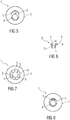
- Figure 7 is a schematic top view of an exemplary fifth embodiment of an earpiece 1 which differs from the third embodiment in that the connector opening 4 is in the centre of the second part 3 and a plurality of vent openings 5 having circular cross sections are arranged around the connector opening 4, e.g. uniformly distributed around the connector opening 4.
- Figure 8 is a schematic top view of an exemplary sixth embodiment of an earpiece 1 similar to the second and fourth embodiment because of the oval cross section of the second part 3; however, it differs from these embodiments in that the vent opening 5 does not have a circular cross section but a crescent shaped cross section.
- the curvature of the crescent shape may be at least approximately concentric with the connector opening 4. This may have an advantageous impact on the size of the second part 3 as the crescent shape allows for arranging the connector opening 4 less off centre.
- Figure 9 is a schematic top view of an exemplary seventh embodiment of an earpiece which is similar to the sixth embodiment but has two vent openings 5 respectively having a crescent shaped cross section.
- the curvature of the crescent shape may be at least approximately concentric with the connector opening 4 and the vent openings 5 may be arranged on opposite sides of the connector opening 4.
- the earpiece 1 is made of at least two different materials, i.e. one for the second part 3 and one for the first part 2. Further, an additional material can be used for the second part 3.
- the parts can be joined in different ways, e.g. via a two-component-molding process, by gluing or laser welding.
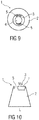
- FIG 10 is a schematic side view of an exemplary sixth embodiment of an earpiece 1.
- the earpiece 1 comprises a first part 2, e.g. a shell, which can be customized to an individual ear canal geometry, and a second part 3, e.g. a medial part, which does not or only marginally change its shape during an in-situ customization process.
- the first part 2 of the earpiece 1 may be made of a shape memory polymer (SMP), which allows for in-situ customization in the ear canal. It may be provided in different sizes in order to fit a great range of ears.
- the shapeable part 2 may have a conical form, so the walls thereof can be tapered, i.e. they can be thinner at a medial end M and become thicker towards a lateral end L.
- the wall thickness can differ for different sizes of the earpiece 1, e.g. three different sizes.
- the second part 3 has an oval cross sectional form. In other exemplary embodiments, the second part 3 may have a different cross sectional form, e.g. circular.
- the second part 3 consists of two components: one component features the connector 7 and a plate with the vent openings 5 and is made of a rather soft material (e.g. a TPU with a hardness of 68 Shore A). This component is overmolded with the shape memory polymer and at the same time the first part 2 is also molded.
- a rather soft material e.g. a TPU with a hardness of 68 Shore A
- vent openings 5 can either be incorporated during the injection molding/ manufacturing process, or afterwards, either in the manufacturing facility (pre-drilled holes) or at the acoustician (in the case of circular vent openings 5).
- vent openings 5 Another option to modify the size of vent openings 5 or to get rid of them is the use of plugs with defined sizes. Depending on the vent opening 5 size needed the respective plug can be mounted on the earpiece 1.
Landscapes
- Engineering & Computer Science (AREA)
- Manufacturing & Machinery (AREA)
- Health & Medical Sciences (AREA)
- General Health & Medical Sciences (AREA)
- Neurosurgery (AREA)
- Otolaryngology (AREA)
- Physics & Mathematics (AREA)
- Acoustics & Sound (AREA)
- Signal Processing (AREA)
- Headphones And Earphones (AREA)
Abstract
The invention relates to an earpiece (1) for a hearing device, comprising:
- a first part (2) comprising a first material wherein the first part is a hollow shapeable part (2) adapted to be inserted into an ear canal of a user,
- a second part (3) comprising a second material, the second part arranged on an end of the shapeable part (2) or at least partially embedded therein.
Description
- The invention relates to an earpiece for a hearing device.
- Earpieces for in-situ customization made of a shape memory material should have a design that allows the acousticians to drill vents, e.g. one straight surface, or should provide a pre-defined hole/ vent, which could be increased in size if needed. Acousticians need the opportunity to provide the client with a defined vent.
- There remains a need for an improved earpiece for a hearing device.
- It is an object of the present invention to provide an improved earpiece for a hearing device.
- The object is achieved by an earpiece for a hearing device according to claim 1.
- Preferred embodiments of the invention are given in the dependent claims.
- According to the invention, an earpiece for a hearing device comprises:
- a first part comprising a first material, wherein the first part is a hollow shapeable part adapted to be inserted into an ear canal of a user,
- a second part comprising a second material, the second part arranged on an end of the first part or at least partially embedded therein.
- In an exemplary embodiment, the second material has a shore A hardness of at least 50. In an exemplary embodiment, the first material is different from the second material, in particular it has a lower shore A hardness, so the second material is more rigid than the first material.
- In an exemplary embodiment, the first material is a shape memory polymer.
- In an exemplary embodiment, the earpiece further comprises at least one vent opening in the second part.
- In an exemplary embodiment, the earpiece further comprises a connector opening in the second part for a connector adapted to connect to a component of a hearing aid.
- In an exemplary embodiment, the first part is conical.
- In an exemplary embodiment, the first part comprises tapering walls with a thickness increasing towards a lateral end. The lateral end is the end pointing outwards, i.e. away from the user of the earpiece when the earpiece is in place within the users ear canal.
- In an exemplary embodiment, the second part has a circular or oval cross section.
- In an exemplary embodiment, the oval cross section has a minor semi-axis smaller than 2.5 mm and a major semi-axis smaller than 3mm.
- In an exemplary embodiment, the vent opening comprises a tubular extension so that the length of the vent opening exceeds a thickness of the second part.
- In an exemplary embodiment, the vent opening has a length of 0.5mm to 12mm, in particular 0.5 mm to 2.5mm and a diameter of 0.3mm to 2 mm, in particular 0.3 mm to 1.5mm.
- In an exemplary embodiment, the vent opening has a circular, oval or crescent shaped cross section.
- In an exemplary embodiment, the second material is at least one of a metal, a ceramic and a polymer, in particular a polyurethane, a thermoplastic polyurethane, a thermoplastic elastomer or a polyamide.
- In an exemplary embodiment, the second part further comprises a third material different than the first and second material.
- In an exemplary embodiment, the earpiece further comprises a connector arranged in the connector hole, the connector made from the second material or from a third material. In an exemplary embodiment, the third material may have a shore A hardness lower than the shore A hardness of the second material.
- In an exemplary embodiment, the first material and the second material are both the same shape memory polymer, wherein the thickness of the second part is greater than the thickness of walls of the first part.
- In an exemplary embodiment, the second part is overmolded with the shape memory polymer.
- According to an aspect of the invention, a method of manufacturing an earpiece as described above is provided, wherein the second part and the first part are joined by at least one of a two-component molding process, gluing and laser welding.
- The present invention provides a solution for the above stated problem. In short, the new earpiece design comprises a first part, e.g. a shell, which can be customized to an individual ear canal geometry, and a second medial part, which does not or only marginally change its shape during the in-situ customization process. In the second part, a connector (e.g. to connect with a component of a hearing aid such as a receiver or a sound tube) and one or more vents (if needed) may be integrated.
- The first part of the earpiece may be made of a shape memory polymer (SMP), which allows for in-situ customization in the ear canal. It shall be provided in different sizes in order to fit a great range of ears. Due to the conicity of the first part the walls thereof can be tapered, i.e. they can be thinner at the medial end and become thicker towards a lateral end. In addition, the wall thickness can differ for different sizes of the earpiece, e.g. three different sizes.
- Further scope of applicability of the present invention will become apparent from the detailed description given hereinafter. However, it should be understood that the detailed description and specific examples, while indicating preferred embodiments of the invention, are given by way of illustration only, since various changes and modifications within the spirit and scope of the invention will become apparent to those skilled in the art from this detailed description.
- The present invention will become more fully understood from the detailed description given hereinbelow and the accompanying drawings which are given by way of illustration only, and thus, are not limiting the present invention, and wherein:
- Figure 1
- is a schematic side view of an exemplary first embodiment of an earpiece,
- Figure 2
- is a schematic top view of the first embodiment of the earpiece,
- Figure 3
- is a schematic top view of an exemplary second embodiment of an earpiece,
- Figure 4
- is a schematic top view of an exemplary third embodiment of an earpiece,
- Figure 5
- is a schematic top view of an exemplary fourth embodiment of an earpiece,
- Figure 6
- is a schematic sectional view of a second part of the fourth embodiment of the earpiece,
- Figure 7
- is a schematic top view of an exemplary fifth embodiment of an earpiece,
- Figure 8
- is a schematic top view of an exemplary sixth embodiment of an earpiece,
- Figure 9
- is a schematic top view of an exemplary seventh embodiment of an earpiece, and
- Figure 10
- is a schematic side view of an exemplary sixth embodiment of an earpiece.
- Corresponding parts are marked with the same reference symbols in all figures.
-
Figure 1 is a schematic side view of an exemplary first embodiment of an earpiece 1.Figure 2 is a schematic top view of the first embodiment of the earpiece 1. The earpiece 1 comprises afirst part 2, e.g. a shell, which can be customized to an individual ear canal geometry, and asecond part 3, e.g. a medial part, which does not or only marginally change its shape during an in-situ customization process. - The
first part 2 of the earpiece 1 may be made of a shape memory polymer (SMP), which allows for in-situ customization in the ear canal. It may be provided in different sizes in order to fit a great range of ears. Thefirst part 2 may have a conical form, so the walls thereof can be tapered, i.e. they can be thinner at a medial end M and become thicker towards a lateral end L. In addition, the wall thickness can differ for different sizes of the earpiece 1, e.g. three different sizes. - In an exemplary embodiment, the
second part 3 has an oval cross sectional form. In other exemplary embodiments, thesecond part 3 may have a different cross sectional form, e.g. circular. -
Figure 3 is a schematic top view of an exemplary second embodiment of an earpiece 1 which differs from the earpiece 1 of the first embodiment in that aconnector opening 4, e.g. to connect with a component of a hearing aid such as a receiver or a sound tube, and one ormore vent openings 5, e.g. respectively having a circular cross section, are integrated in thesecond part 3. Theconnector opening 4 may typically be significantly larger in diameter than the one ormore vent openings 5. Theconnector opening 4 may have a circular cross section. -
Figure 4 is a schematic top view of an exemplary third embodiment of an earpiece 1 which differs from the earpiece 1 of the second embodiment in that thesecond part 3 has a circular cross sectional form. Theconnector opening 4 is off center to provide space for thevent opening 5.
Infigures 3 and 4 thesecond part 3 comprises theconnector opening 4 for attaching a component of a hearing aid such as a receiver or a sound tube for connecting to a receiver. Moreover, thesecond part 3 has space to drill one ormore vent openings 5 or featurespre-manufactured vent openings 5. Thesecond part 3 shall be as large as needed to accommodate theconnector opening 4 and the one ormore vent openings 5 and as small as possible in order to allow for a high fit rate. Thesecond part 3 shall have the same size for all earpiece 1 sizes, but can also be larger for the larger earpiece 1 sizes. In an exemplary embodiment, the ovalsecond part 3 offigure 3 features a minor semi-axis smaller than 2.5 mm and a major semi-axis smaller than 3mm. Due to the connector and receiver limiting space in the earpiece 1, thevent openings 5 shall ideally be integrated in thesecond part 3. To calculate a vent mass of a standard vent opening 5 (e.g. with a length of approximately 12 mm and a diameter of 1.4 mm) a simplified equation (see equation (1) below) can be used where the vent mass is proportional to the length of thevent opening 5 and inversely proportional to the cross section of thevent opening 5. Forshort vents openings 5, i.e. thevent openings 5 are integrated in thesecond part 3, the length of thevent opening 5 must be corrected with a term dL as shown in equation (2) below. For calculation of the resistance of thevent opening 5, which is used for the calculation of the vent mass VM, the following two simplified formulas can be used for standard andthin vent openings 5 with a round, e.g. circular, cross section:
vent opening 5, A=cross sectional area of the vent opening
vent opening 5 - Based on the above equation 1, the vent mass for different sizes of
vent openings 5 of standard earpieces 1 (e.g. slim tips) as suggested by Phonak's fitting software "Target" was calculated (see Table 1). These (approximate) results for the vent mass andequation 2 were taken to calculate the respective vent diameters for the shape memory polymer earpieces 1 according to the invention for vent lengths of 1.5 and 1 mm, respectively, which corresponds to the thickness of thesecond part 3, as shown in Table 2. In short, the range of vent diameters is between 0.2 and 1 mm, ideally between 0.31 mm and 0.8 mm. A drawback of these short andsmall vent openings 5 is that the manufacturing tolerances have a larger impact on the acoustic performance of the earpiece 1 than withlarger vent openings 5. Consequently, in one design approach a slightly longer (e.g. 3 mm or 5 mm) andlarger vent opening 5 may be integrated in the second part (see schematic inFigure 5 ). -
Figure 5 is a schematic top view of an exemplary fourth embodiment of an earpiece 1, which differs from the second embodiment in that thevent opening 5 is slightly longer (e.g. 3 mm or 5 mm) and larger.Figure 6 is a schematic sectional view of thesecond part 3 of the fourth embodiment of the earpiece 1. It will be appreciated that thevent opening 5 comprises atubular extension 6 so that the length of thevent opening 5 exceeds a thickness of thesecond part 3. Thetubular extension 6 may consist of the same material as thesecond part 3 and may be integrally formed with thesecond part 3.Table 1: Vent masses calculated for different sizes of vent openings 5 of standard earpieces (e.g. slim tips)Standard L 12 12 12 D 1.4 1 2 A 1.54 0.79 3.14 VM 7.80 15.28 3.82 Table 2: Diameters calculated for the thin vent openings 5 of shape memory polymer earpieces 1 with vent masses similar to those of the standard earpiecesSMP L 1.5 1.5 1.5 1 D 0.55 0.375 0.8 0.31 A 0.24 0.11 0.50 0.08 dL 0.33 0.225 0.48 0.186 VM 7.70 15.62 3.94 15.71 -
Figure 7 is a schematic top view of an exemplary fifth embodiment of an earpiece 1 which differs from the third embodiment in that theconnector opening 4 is in the centre of thesecond part 3 and a plurality ofvent openings 5 having circular cross sections are arranged around theconnector opening 4, e.g. uniformly distributed around theconnector opening 4. -
Figure 8 is a schematic top view of an exemplary sixth embodiment of an earpiece 1 similar to the second and fourth embodiment because of the oval cross section of thesecond part 3; however, it differs from these embodiments in that thevent opening 5 does not have a circular cross section but a crescent shaped cross section. The curvature of the crescent shape may be at least approximately concentric with theconnector opening 4. This may have an advantageous impact on the size of thesecond part 3 as the crescent shape allows for arranging theconnector opening 4 less off centre. -
Figure 9 is a schematic top view of an exemplary seventh embodiment of an earpiece which is similar to the sixth embodiment but has twovent openings 5 respectively having a crescent shaped cross section. The curvature of the crescent shape may be at least approximately concentric with theconnector opening 4 and thevent openings 5 may be arranged on opposite sides of theconnector opening 4. - Various options exist for the material and manufacturing of the
second part 3 and the entire earpiece 1. Generally, the earpiece 1 is made of at least two different materials, i.e. one for thesecond part 3 and one for thefirst part 2. Further, an additional material can be used for thesecond part 3. The parts can be joined in different ways, e.g. via a two-component-molding process, by gluing or laser welding. - Strong adhesion between the
first part 2, e.g. made out of a shape memory polymer, and thesecond part 3 containing thevent opening 5 according to this invention and aconnector opening 5 or the connector itself, is desirable, especially if a two-component-molding process is applied. Qualitative adhesion experiments between the shape memory polymer and different materials (see Table 3) were thus performed in order to test the adhesion of various connector materials with a preferred shape memory polymer (e.g. a segmented poly(ester urethane), as described in ACS Appl. Mater. Interfaces 2018, 10, 24829-24839 andPCT/EP2019/058567 - (i) Hot-cold adhesion: Except for Tecoflex SG 80A, the shape memory polymer strips were heated on a hot stage to 180 °C. The films made from the prospective connector materials listed in Table 3 were brought into contact with the melted shape memory polymer to create lap joints with an overlap area of approximately 1 cm2. Gentle pressure was applied to provide good interfacial contact, before the lap joints thus created were removed from the hot stage and allowed to cool to ambient temperature. In the case of Tecoflex SG 80A, the process was changed; here the Tecoflex SG80A strip was heated on a hot stage to 150 °C and the shape memory polymer film was brought into contact with the melted Tecoflex strip and the lap joints were finished as outlined above. The lap joints thus produced were stretched in order to test the adhesion between the two strips. Efficient adhesion was observed for lap joints made with the shape memory polymer and the polyurethanes (PU, TPU) without observing any delamination at the interphase except for Texin 270 and Desmopan 3072 D, which both have a relatively high shore hardness. Complete delamination was observed between the shape memory polymer and polyamides or TPE based materials.
- (ii) Hot-hot adhesion: Both the shape memory polymer strips and the strips made from the prospective connector materials listed in Table 3 were placed in a hot press, brought into contact to create lap joints with an overlap area of approximately 1 cm2, and the assemblies were pressed for 45 s at 1 bar and 150 °C (Tecoflex SG 80A), 180 °C (all other polymers) and in the case of Nylon 6.12 also 220 °C. The lap joints thus created were removed from the press and allowed to cool to ambient temperature. Efficient adhesion was achieved between the shape memory polymer and the TPUs and the PAs. However, cohesive failure of the shape memory polymer attached to Nylon 12 was observed when the sample stretched. TPE based For-Tec E was delaminated from the shape memory polymer and cohesive failure of Thermolast K TC3 PAN occurred, which has low shore hardness, when the sample stretched.
- According to the results of these experiments, some material and manufacturing options are listed, based on the assumption that especially the hot-hot adhesion tests allow to predict the outcome of a two-component-molding process:
- (i) the connector and the
second part 3 are made from the same material (e.g. a TPU with a hardness of 65-85 Shore A) and as one part, and the shell/first part 2 made of the shape memory polymer is thermally bonded with this assembly. - (ii) the connector is made of a rather soft material (e.g. a TPU with a hardness of 68 Shore A), the
second part 3 is made of another harder TPU (e.g. with a hardness of 85 Shore A) and thefirst part 2 is made of the shape memory polymer. - (iii) the connector is made of a rather soft material (e.g. a TPU with a hardness of 68 Shore A), the
second part 3 and thefirst part 2 are made of the shape memory polymer, but thesecond part 3 features a greater wall thickness to avoid deformation of the material during in-situ customization. In this set-up, a plug could be used to keep thevent opening 5 open during in-situ customization which can be removed afterwards. - (iv) the
second part 3 consists of two components: one component features the connector 7 and a plate with thevent openings 5 and is made of a rather soft material (e.g. a TPU with a hardness of 68 Shore A). This component is overmolded with the shape memory polymer and at the same time thefirst part 2 is also molded (seeFigure 10 ). -
Figure 10 is a schematic side view of an exemplary sixth embodiment of an earpiece 1. The earpiece 1 comprises afirst part 2, e.g. a shell, which can be customized to an individual ear canal geometry, and asecond part 3, e.g. a medial part, which does not or only marginally change its shape during an in-situ customization process. - The
first part 2 of the earpiece 1 may be made of a shape memory polymer (SMP), which allows for in-situ customization in the ear canal. It may be provided in different sizes in order to fit a great range of ears. Theshapeable part 2 may have a conical form, so the walls thereof can be tapered, i.e. they can be thinner at a medial end M and become thicker towards a lateral end L. In addition, the wall thickness can differ for different sizes of the earpiece 1, e.g. three different sizes. In an exemplary embodiment, thesecond part 3 has an oval cross sectional form. In other exemplary embodiments, thesecond part 3 may have a different cross sectional form, e.g. circular. - The
second part 3 consists of two components: one component features the connector 7 and a plate with thevent openings 5 and is made of a rather soft material (e.g. a TPU with a hardness of 68 Shore A). This component is overmolded with the shape memory polymer and at the same time thefirst part 2 is also molded. - The vent openings 5 (see above for the various options of the vent openings 5) can either be incorporated during the injection molding/ manufacturing process, or afterwards, either in the manufacturing facility (pre-drilled holes) or at the acoustician (in the case of circular vent openings 5).
- Another option to modify the size of
vent openings 5 or to get rid of them is the use of plugs with defined sizes. Depending on thevent opening 5 size needed the respective plug can be mounted on the earpiece 1. -
- 1
- earpiece
- 2
- first part
- 3
- second part
- 4
- connector opening
- 5
- vent opening
- 6
- tubular extension
- 7
- connector
- L
- lateral end
- M
- medial end
| Name | Type* | Shore Hardness |
| Tecoflex SG 80A | PU | 72A |
| Elastollan 1185 A 10000 | TPU | 83A |
| Texin 285 | TPU | 85A |
| Pellethane 2103 | TPU | 92A |
| Texin 270 | TPU | 95A |
| Desmopan DP 3072 D | TPU | 98A |
| For-Tec E mid gray | TPE | 60A |
| Thermolast K TC3 PAN nature | TPE | 29A |
| Nylon 12 | PA | 100A |
| Nylon 6.12 | PA | - |
| *PU:Polyurethane, TPU:Thermoplastic polyurethane, PA:Polyamide, TPE:Thermoplastic elastomer |
Claims (15)
- An earpiece (1) for a hearing device, comprising:- a first part (2) comprising a first material wherein the first part is a hollow shapeable part adapted to be inserted into an ear of a user,- a second part (3) comprising a second material, the second part arranged on an end of the first part (2) or at least partially embedded therein.
- The earpiece (1) of claim 1, wherein the first material is a shape memory polymer.
- The earpiece (1) of claim 1 or 2, wherein the second material has a shore A hardness of at least 50.
- The earpiece (1) according to any one of the preceding claims, further comprising at least one vent opening (5) in the second part (3) and/or a connector opening (4) in the second part (3) for a connector (7) adapted to connect to a component of a hearing aid.
- The earpiece (1) according to any one of the preceding claims, wherein the first part (2) is conical and/or wherein the first part (2) comprises tapering walls with a thickness increasing towards a lateral end (L).
- The earpiece (1) according to any one of the preceding claims, wherein the second part (3) has a circular or oval cross section, in particular the oval cross section having a minor semi-axis smaller than 2.5 mm and a major semi-axis smaller than 3mm.
- The earpiece (1) according to any one of the claims 4 to 6, wherein the vent opening (5) comprises a tubular extension (6) so that the length of the vent opening (5) exceeds a thickness of the second part (3).
- The earpiece according to any one of the claims 4 to 7, wherein the vent opening (5) has a length of 0.5mm to 12mm and a diameter of 0.3mm to 2mm.
- The earpiece (1) according to any one of the claims 4 to 8, wherein the vent opening (5) has a circular, oval or crescent shaped cross section.
- The earpiece (1) according to any one of the preceding claims, wherein the second material is at least one of a metal, a ceramic and a polymer, in particular a polyurethane, a thermoplastic polyurethane or a polyamide.
- The earpiece (1) according to any one of the preceding claims, wherein the second part (3) further comprises a third material different than the first and second material.
- The earpiece (1) according to any one of the claims 4 to 11, further comprising a connector (7) arranged in the connector opening (4), the connector (7) made from the second material or from a third material.
- The earpiece (1) according to any one of the claims 4 to 12, wherein the first material and the second material are both the same shape memory polymer, wherein the thickness of the second part (3) is greater than the thickness of walls of the first part (2).
- The earpiece (1) according to any one of the claims 3 to 13, wherein the second part (3) is overmolded with the shape memory polymer.
- A method of manufacturing an earpiece (1) according to any one of the preceding claims, wherein the second part (3) and the first part (2) are joined by at least one of a two-component molding process, gluing and laser welding.
Priority Applications (3)
| Application Number | Priority Date | Filing Date | Title |
|---|---|---|---|
| EP19218042.0A EP3840411A1 (en) | 2019-12-19 | 2019-12-19 | Earpiece for a hearing device |
| CN202011458485.0A CN113015072A (en) | 2019-12-19 | 2020-12-11 | Earplug for a hearing device |
| US17/123,969 US20210195351A1 (en) | 2019-12-19 | 2020-12-16 | Earpiece for a Hearing Device |
Applications Claiming Priority (1)
| Application Number | Priority Date | Filing Date | Title |
|---|---|---|---|
| EP19218042.0A EP3840411A1 (en) | 2019-12-19 | 2019-12-19 | Earpiece for a hearing device |
Publications (1)
| Publication Number | Publication Date |
|---|---|
| EP3840411A1 true EP3840411A1 (en) | 2021-06-23 |
Family
ID=68965906
Family Applications (1)
| Application Number | Title | Priority Date | Filing Date |
|---|---|---|---|
| EP19218042.0A Pending EP3840411A1 (en) | 2019-12-19 | 2019-12-19 | Earpiece for a hearing device |
Country Status (3)
| Country | Link |
|---|---|
| US (1) | US20210195351A1 (en) |
| EP (1) | EP3840411A1 (en) |
| CN (1) | CN113015072A (en) |
Families Citing this family (1)
| Publication number | Priority date | Publication date | Assignee | Title |
|---|---|---|---|---|
| US20230269509A1 (en) * | 2022-02-22 | 2023-08-24 | Apple Inc. | Ear tip for portable wireless listening device |
Citations (4)
| Publication number | Priority date | Publication date | Assignee | Title |
|---|---|---|---|---|
| US20070183613A1 (en) * | 2004-05-28 | 2007-08-09 | Juneau Roger P | Self forming in-the-ear hearing aid with conical stent |
| JP2012075850A (en) * | 2010-10-04 | 2012-04-19 | Mitsuyo Sasaki | Earplug with mounting aid |
| WO2018099562A1 (en) * | 2016-12-01 | 2018-06-07 | Sonova Ag | A method of customizing a hearing device component, a hearing device component and a hearing device |
| US20180359579A1 (en) * | 2009-07-25 | 2018-12-13 | Eargo, Inc. | Adjustable Securing Mechanism |
Family Cites Families (19)
| Publication number | Priority date | Publication date | Assignee | Title |
|---|---|---|---|---|
| US6695093B1 (en) * | 2000-01-13 | 2004-02-24 | Aearo Company | Earplug |
| CN101297593B (en) * | 2005-08-01 | 2012-05-23 | Gn瑞声达A/S | A hearing device with an open earpiece having a short vent |
| AU2006347144B2 (en) * | 2006-08-07 | 2010-08-12 | Widex A/S | Hearing aid, method for in-situ occlusion effect and directly transmitted sound measurement and vent size determination method |
| US8649540B2 (en) * | 2009-10-30 | 2014-02-11 | Etymotic Research, Inc. | Electronic earplug |
| US8616214B2 (en) * | 2011-04-06 | 2013-12-31 | Kimberly-Clark Worldwide, Inc. | Earplug having a resilient core structure |
| WO2013014852A1 (en) * | 2011-07-22 | 2013-01-31 | パナソニック株式会社 | Earphone |
| CN202663526U (en) * | 2011-12-01 | 2013-01-09 | 广州艾尔慢回弹耳塞有限公司 | Slowly resilient earplug cotton |
| CN102413410A (en) * | 2011-12-16 | 2012-04-11 | 江苏贝泰福医疗科技有限公司 | Digital hearing-aid |
| CN104041077B (en) * | 2011-12-23 | 2017-05-24 | 索诺瓦公司 | Hearing device with a tip-plate assembly and method of manufacturing a hearing device |
| US9451353B2 (en) * | 2012-02-08 | 2016-09-20 | Decibullz Llc | Moldable earpiece system |
| CN102547515B (en) * | 2012-02-21 | 2014-09-03 | 江苏贝泰福医疗科技有限公司 | Music earphone |
| CN103327435A (en) * | 2013-07-15 | 2013-09-25 | 江苏贝泰福医疗科技有限公司 | Non-separable deformable ear hook of intra-aural receiving behind-the-ear BTE |
| DK3304932T3 (en) * | 2015-05-27 | 2020-08-03 | Sivantos Pte Ltd | HEARING DEVICE WITH PLUG CONNECTION FOR EAR PIECE |
| CN105050016A (en) * | 2015-08-14 | 2015-11-11 | 张洪飞 | In-ear hearing aid control system |
| DK3142386T3 (en) * | 2015-09-08 | 2019-07-08 | Oticon As | SEALING EARRING |
| US10158933B2 (en) * | 2016-04-21 | 2018-12-18 | Bose Corporation | Custom-molding in-ear headphone ear tips |
| US10531174B2 (en) * | 2016-10-13 | 2020-01-07 | Bose Corporation | Earpiece employing cooling and sensation inducing materials |
| CN111787977A (en) * | 2018-02-27 | 2020-10-16 | 领先仿生公司 | Sound transmission device for audiometric measurement |
| US10623861B2 (en) * | 2018-08-31 | 2020-04-14 | Bose Corporation | Wearable devices using shape memory polymers |
-
2019
- 2019-12-19 EP EP19218042.0A patent/EP3840411A1/en active Pending
-
2020
- 2020-12-11 CN CN202011458485.0A patent/CN113015072A/en active Pending
- 2020-12-16 US US17/123,969 patent/US20210195351A1/en not_active Abandoned
Patent Citations (4)
| Publication number | Priority date | Publication date | Assignee | Title |
|---|---|---|---|---|
| US20070183613A1 (en) * | 2004-05-28 | 2007-08-09 | Juneau Roger P | Self forming in-the-ear hearing aid with conical stent |
| US20180359579A1 (en) * | 2009-07-25 | 2018-12-13 | Eargo, Inc. | Adjustable Securing Mechanism |
| JP2012075850A (en) * | 2010-10-04 | 2012-04-19 | Mitsuyo Sasaki | Earplug with mounting aid |
| WO2018099562A1 (en) * | 2016-12-01 | 2018-06-07 | Sonova Ag | A method of customizing a hearing device component, a hearing device component and a hearing device |
Non-Patent Citations (1)
| Title |
|---|
| ACS APPL. MATER. INTERFACES, vol. 10, 2018, pages 24829 - 24839 |
Also Published As
| Publication number | Publication date |
|---|---|
| CN113015072A (en) | 2021-06-22 |
| US20210195351A1 (en) | 2021-06-24 |
Similar Documents
| Publication | Publication Date | Title |
|---|---|---|
| US5002151A (en) | Ear piece having disposable, compressible polymeric foam sleeve | |
| CN103781012B (en) | Earplug, the method for manufacturing earplug and the earphone including earplug | |
| US10034105B2 (en) | Article with internal light source for fitting in-situ and related devices and methods | |
| US7837005B2 (en) | Mushroom-shaped push-in foam eartip for use with high-fidelity insert earphones | |
| JP5271412B2 (en) | Non-roll type ear tip | |
| EP3249945B1 (en) | Earbud | |
| EP3041259A1 (en) | In-ear headphones having a flexible nozzle and related methods | |
| US20180020296A1 (en) | Adjustable venting for hearing instruments | |
| EP1884140B1 (en) | A hook for a hearing aid | |
| EP3840411A1 (en) | Earpiece for a hearing device | |
| KR20090097875A (en) | Self-fitting device for location in an ear canal | |
| US20170339499A1 (en) | An impression-taking pad, a method of impression-taking, an impression, a method of manufacturing a custom ear canal shell, a custom ear canal shell and a hearing device | |
| US7891360B2 (en) | Earplug and manufacturing method | |
| US7864972B2 (en) | Customized in-ear interface for acoustic equipment and method | |
| EP3841761B1 (en) | Earpiece and manufacturing method and customization method of the earpiece | |
| JP2002536932A (en) | Molded hearing aid housing | |
| EP3675782B1 (en) | Earplug assembly and method for forming the same | |
| EP3326388B1 (en) | A hearing device for being worn at least partly within an ear canal and a method for manufacturing such a hearing device | |
| EP2898704B1 (en) | Encapsulated hearing device | |
| JP2004113557A (en) | Bat for baseball or softball | |
| US11818551B2 (en) | Method for adapting an otoplastic of a hearing aid, hearing aid, and hearing aid system | |
| WO2021133747A1 (en) | Apparatus and method for an earpiece-foam shaping/sizing tool and container | |
| CN101180918A (en) | Crook for hearing aid | |
| WO2006022354A1 (en) | Eccentric weight and method of producing the weight, vibrating motor and method of producing the motor, and portable apparatus | |
| DE102006059136A1 (en) | Hearing aid e.g. in-the-ear hearing aid, producing method, involves inserting sound hose through sound delivery port until stopper attaches at inner side of hearing aid bowl, and shortening hose outside of bowl to final length |
Legal Events
| Date | Code | Title | Description |
|---|---|---|---|
| PUAI | Public reference made under article 153(3) epc to a published international application that has entered the european phase |
Free format text: ORIGINAL CODE: 0009012 |
|
| STAA | Information on the status of an ep patent application or granted ep patent |
Free format text: STATUS: REQUEST FOR EXAMINATION WAS MADE |
|
| 17P | Request for examination filed |
Effective date: 20210218 |
|
| AK | Designated contracting states |
Kind code of ref document: A1 Designated state(s): AL AT BE BG CH CY CZ DE DK EE ES FI FR GB GR HR HU IE IS IT LI LT LU LV MC MK MT NL NO PL PT RO RS SE SI SK SM TR |
|
| STAA | Information on the status of an ep patent application or granted ep patent |
Free format text: STATUS: EXAMINATION IS IN PROGRESS |
|
| 17Q | First examination report despatched |
Effective date: 20230511 |