EP3834724A2 - Disposable painless lancet and lancing devices for use therewith - Google Patents
Disposable painless lancet and lancing devices for use therewith Download PDFInfo
- Publication number
- EP3834724A2 EP3834724A2 EP21150771.0A EP21150771A EP3834724A2 EP 3834724 A2 EP3834724 A2 EP 3834724A2 EP 21150771 A EP21150771 A EP 21150771A EP 3834724 A2 EP3834724 A2 EP 3834724A2
- Authority
- EP
- European Patent Office
- Prior art keywords
- needle
- skin
- spring
- needle body
- lancet
- Prior art date
- Legal status (The legal status is an assumption and is not a legal conclusion. Google has not performed a legal analysis and makes no representation as to the accuracy of the status listed.)
- Withdrawn
Links
Images


Classifications
-
- A—HUMAN NECESSITIES
- A61—MEDICAL OR VETERINARY SCIENCE; HYGIENE
- A61B—DIAGNOSIS; SURGERY; IDENTIFICATION
- A61B5/00—Measuring for diagnostic purposes; Identification of persons
- A61B5/15—Devices for taking samples of blood
- A61B5/151—Devices specially adapted for taking samples of capillary blood, e.g. by lancets, needles or blades
- A61B5/15186—Devices loaded with a single lancet, i.e. a single lancet with or without a casing is loaded into a reusable drive device and then discarded after use; drive devices reloadable for multiple use
- A61B5/15188—Constructional features of reusable driving devices
- A61B5/15192—Constructional features of reusable driving devices comprising driving means, e.g. a spring, for retracting the lancet unit into the driving device housing
-
- A—HUMAN NECESSITIES
- A61—MEDICAL OR VETERINARY SCIENCE; HYGIENE
- A61B—DIAGNOSIS; SURGERY; IDENTIFICATION
- A61B5/00—Measuring for diagnostic purposes; Identification of persons
- A61B5/15—Devices for taking samples of blood
- A61B5/151—Devices specially adapted for taking samples of capillary blood, e.g. by lancets, needles or blades
- A61B5/15142—Devices intended for single use, i.e. disposable
-
- A—HUMAN NECESSITIES
- A61—MEDICAL OR VETERINARY SCIENCE; HYGIENE
- A61B—DIAGNOSIS; SURGERY; IDENTIFICATION
- A61B5/00—Measuring for diagnostic purposes; Identification of persons
- A61B5/15—Devices for taking samples of blood
- A61B5/150007—Details
- A61B5/150015—Source of blood
- A61B5/150022—Source of blood for capillary blood or interstitial fluid
-
- A—HUMAN NECESSITIES
- A61—MEDICAL OR VETERINARY SCIENCE; HYGIENE
- A61B—DIAGNOSIS; SURGERY; IDENTIFICATION
- A61B5/00—Measuring for diagnostic purposes; Identification of persons
- A61B5/15—Devices for taking samples of blood
- A61B5/150007—Details
- A61B5/150053—Details for enhanced collection of blood or interstitial fluid at the sample site, e.g. by applying compression, heat, vibration, ultrasound, suction or vacuum to tissue; for reduction of pain or discomfort; Skin piercing elements, e.g. blades, needles, lancets or canulas, with adjustable piercing speed
- A61B5/150106—Means for reducing pain or discomfort applied before puncturing; desensitising the skin at the location where body is to be pierced
- A61B5/150152—Means for reducing pain or discomfort applied before puncturing; desensitising the skin at the location where body is to be pierced by an adequate mechanical impact on the puncturing location
-
- A—HUMAN NECESSITIES
- A61—MEDICAL OR VETERINARY SCIENCE; HYGIENE
- A61B—DIAGNOSIS; SURGERY; IDENTIFICATION
- A61B5/00—Measuring for diagnostic purposes; Identification of persons
- A61B5/15—Devices for taking samples of blood
- A61B5/150007—Details
- A61B5/150175—Adjustment of penetration depth
- A61B5/15019—Depth adjustment mechanism using movable stops located inside the piercing device housing and limiting the travel of the drive mechanism
-
- A—HUMAN NECESSITIES
- A61—MEDICAL OR VETERINARY SCIENCE; HYGIENE
- A61B—DIAGNOSIS; SURGERY; IDENTIFICATION
- A61B5/00—Measuring for diagnostic purposes; Identification of persons
- A61B5/15—Devices for taking samples of blood
- A61B5/150007—Details
- A61B5/150374—Details of piercing elements or protective means for preventing accidental injuries by such piercing elements
- A61B5/150381—Design of piercing elements
- A61B5/150503—Single-ended needles
- A61B5/150519—Details of construction of hub, i.e. element used to attach the single-ended needle to a piercing device or sampling device
-
- A—HUMAN NECESSITIES
- A61—MEDICAL OR VETERINARY SCIENCE; HYGIENE
- A61B—DIAGNOSIS; SURGERY; IDENTIFICATION
- A61B5/00—Measuring for diagnostic purposes; Identification of persons
- A61B5/15—Devices for taking samples of blood
- A61B5/151—Devices specially adapted for taking samples of capillary blood, e.g. by lancets, needles or blades
- A61B5/15101—Details
- A61B5/15103—Piercing procedure
- A61B5/15107—Piercing being assisted by a triggering mechanism
- A61B5/15113—Manually triggered, i.e. the triggering requires a deliberate action by the user such as pressing a drive button
-
- A—HUMAN NECESSITIES
- A61—MEDICAL OR VETERINARY SCIENCE; HYGIENE
- A61B—DIAGNOSIS; SURGERY; IDENTIFICATION
- A61B5/00—Measuring for diagnostic purposes; Identification of persons
- A61B5/15—Devices for taking samples of blood
- A61B5/151—Devices specially adapted for taking samples of capillary blood, e.g. by lancets, needles or blades
- A61B5/15101—Details
- A61B5/15115—Driving means for propelling the piercing element to pierce the skin, e.g. comprising mechanisms based on shape memory alloys, magnetism, solenoids, piezoelectric effect, biased elements, resilient elements, vacuum or compressed fluids
- A61B5/15117—Driving means for propelling the piercing element to pierce the skin, e.g. comprising mechanisms based on shape memory alloys, magnetism, solenoids, piezoelectric effect, biased elements, resilient elements, vacuum or compressed fluids comprising biased elements, resilient elements or a spring, e.g. a helical spring, leaf spring, or elastic strap
-
- A—HUMAN NECESSITIES
- A61—MEDICAL OR VETERINARY SCIENCE; HYGIENE
- A61B—DIAGNOSIS; SURGERY; IDENTIFICATION
- A61B5/00—Measuring for diagnostic purposes; Identification of persons
- A61B5/15—Devices for taking samples of blood
- A61B5/151—Devices specially adapted for taking samples of capillary blood, e.g. by lancets, needles or blades
- A61B5/15186—Devices loaded with a single lancet, i.e. a single lancet with or without a casing is loaded into a reusable drive device and then discarded after use; drive devices reloadable for multiple use
- A61B5/15188—Constructional features of reusable driving devices
- A61B5/15192—Constructional features of reusable driving devices comprising driving means, e.g. a spring, for retracting the lancet unit into the driving device housing
- A61B5/15194—Constructional features of reusable driving devices comprising driving means, e.g. a spring, for retracting the lancet unit into the driving device housing fully automatically retracted, i.e. the retraction does not require a deliberate action by the user, e.g. by terminating the contact with the patient's skin
-
- A—HUMAN NECESSITIES
- A61—MEDICAL OR VETERINARY SCIENCE; HYGIENE
- A61B—DIAGNOSIS; SURGERY; IDENTIFICATION
- A61B5/00—Measuring for diagnostic purposes; Identification of persons
- A61B5/15—Devices for taking samples of blood
- A61B5/150007—Details
- A61B5/150374—Details of piercing elements or protective means for preventing accidental injuries by such piercing elements
- A61B5/150381—Design of piercing elements
- A61B5/150412—Pointed piercing elements, e.g. needles, lancets for piercing the skin
-
- A—HUMAN NECESSITIES
- A61—MEDICAL OR VETERINARY SCIENCE; HYGIENE
- A61B—DIAGNOSIS; SURGERY; IDENTIFICATION
- A61B5/00—Measuring for diagnostic purposes; Identification of persons
- A61B5/15—Devices for taking samples of blood
- A61B5/150007—Details
- A61B5/150374—Details of piercing elements or protective means for preventing accidental injuries by such piercing elements
- A61B5/150534—Design of protective means for piercing elements for preventing accidental needle sticks, e.g. shields, caps, protectors, axially extensible sleeves, pivotable protective sleeves
- A61B5/150633—Protective sleeves which are axially extensible, e.g. sleeves connected to, or integrated in, the piercing or driving device; pivotable protective sleeves
Definitions
- the present invention relates to disposable painless lancets and lancing devices for use therewith, which the subject can hardly feel to such an extent that a pain can be neglected.
- the lancets and the lancing devices of the present invention are configured such that a bump spring strikes a skin in advance before a needle penetrates the skin so as to disturb the skin nerve, and further configured such that, after the needle stabs the skin, the needle can be momentarily released out of the skin due to the restoring force of the bump spring so that a time required for the needle to stay in the skin is very short, and the needle can be adjusted to penetrate deep or shallow by allowing the needle to be inserted only a certain depth of skin.
- the lancet is disposable, there is always a risk that secondary infections such as AIDS and hepatitis can be infected unless special care is taken after use.
- Korean Patent No. 10-0932946 discloses a device for securing a straight direction when a lancing needle penetrates the skin, but the device is not related to a function of eliminating a pain.
- An aspect of the second embodiment of the present invention provides the disposable painless lancet, wherein the needle body has an elongated spiral part disposed at one end thereof; wherein one end of the needle is embedded in the center of the end of the spiral part; wherein a spring body in the form of a nut having a spiral disposed therein so as to be screwed with the elongated spiral part is included; and wherein one end of the bump spring is embedded or fixed to the spring body.
- the lancing device includes: a casing 100 that forms an outer appearance of the device; and a launch part 200 for launching a bumper part 300 having a bumper 320 and a needle body 341 to strike the skin, in which the bumper part 300 has a needle body holder 310 including the bumper 320 that primarily strikes the skin and a needle spring 342 that strikes the skin secondarily.
- the bumper part 300 When the bumper part 300 is launched, the bumper part 300 first strikes the skin by the inertial force at the time of launching, and then continues to press the skin while being in contact with the skin by the compressive force of a bump spring 303. At this time, the bump spring 303 is compressed due to the inertial force of the bumper 320, which is momentarily maintained, and the inertial force of the needle body holder 310 including the lancet.
- a stop bar 323 seated on an upper end of the bumper 320 then moves up to a tip of an adjusting member flange 351 to be properly adjusted along a rectangular hole 313 of a cylindrical body 312, and the needle spring 342 of the needle body 341 strikes the skin.
- the trigger pin 212 passing through the launch pestle 203 connected to the launch spring 210 is slid along the upper side of the rectangular hole 211 and is "twisted", and then is pushed along the transverse slits of the ' ⁇ '-shaped slits 215 and momentarily falls below the longitudinal slits of the ' ⁇ '-shaped slits 215, whereby the launch pestle 203 can be launched.
- a launching force is transmitted to the bumper part 300 through the coupling shaft 213, so that the bumper 320 strikes the skin.
- the push member 206 is pushed again, the launch body 201 and the launch pestle 203 return to the transverse slits of the ' ⁇ '-shaped slits 215 and return to the standing state.
- the material of the needle body 10 is preferably plastics.
- the needle body 10 may have a columnar structure, preferably a skeleton structure as shown in FIGS. 14 and 15 .
- FIG. 14 (b) shows the state of the disposable painless lancet when contacted with the skin ( 40 in FIG. 26 ) after being launched from the lancing device for sampling blood.
- the bump spring 20 momentarily strikes a skin 40.
- the skin 40 is first impacted by the momentary striking applied by the bump spring 20, disturbing the skin nerve not to feel the pain.
- the needle 30 is momentarily released out of the skin 40 due to the force of restoration of the bump spring 20 and the time the needle 30 stays on the skin is very short. Also, the needle 30 does not penetrate excessively below the subcutaneous tissue.
- the bump spring 20 determines a limit of a length that can be pressed immediately after striking the skin 40 and the needle 30 can penetrate the skin 40, the needle 30 penetrates the skin 40 only by a predetermined length. Therefore, it is possible to prevent the needle 30 from being excessively penetrated into the skin 40 more than necessary for sampling blood.
- a ring-shaped protrusion 1315 is formed in the upper position of the needle body holder 1300 so as to be engaged with a coupling groove 1217 of a coupling shaft 1213.
- the needle body holder 1300 is open at its lower portion and has one incision groove 1313 cut from the lower portion to the middle portion thereof.
- the incision groove 1313 is configured to elastically hold the needle body 10 firmly.
- the front cap 1101 of the casing 1100 has a shape gradually tapering from the top to the bottom.
- a circular engagement protrusion 1105 is formed on the inside of the front cap 1101 to limit the downward movement of the lower surface of a cylindrical body 1312.
- a guide hole 1106 is formed from the engagement protrusion 1105 to the lower end of the front cap 1101 to guide the needle body 10 and the bump spring 20 in a predetermined direction.
Landscapes
- Health & Medical Sciences (AREA)
- Life Sciences & Earth Sciences (AREA)
- Heart & Thoracic Surgery (AREA)
- Surgery (AREA)
- Biophysics (AREA)
- Pathology (AREA)
- Engineering & Computer Science (AREA)
- Biomedical Technology (AREA)
- Hematology (AREA)
- Medical Informatics (AREA)
- Molecular Biology (AREA)
- Physics & Mathematics (AREA)
- Animal Behavior & Ethology (AREA)
- General Health & Medical Sciences (AREA)
- Public Health (AREA)
- Veterinary Medicine (AREA)
- Dermatology (AREA)
- Pain & Pain Management (AREA)
- Measurement Of The Respiration, Hearing Ability, Form, And Blood Characteristics Of Living Organisms (AREA)
Abstract
Description
- The present invention relates to disposable painless lancets and lancing devices for use therewith, which the subject can hardly feel to such an extent that a pain can be neglected. The lancets and the lancing devices of the present invention are configured such that a bump spring strikes a skin in advance before a needle penetrates the skin so as to disturb the skin nerve, and further configured such that, after the needle stabs the skin, the needle can be momentarily released out of the skin due to the restoring force of the bump spring so that a time required for the needle to stay in the skin is very short, and the needle can be adjusted to penetrate deep or shallow by allowing the needle to be inserted only a certain depth of skin.
- A small amount of blood can be shed to remove coagulum and metabolic waste matter in oriental medicine. In addition, a small amount of blood can be also sampled to measure blood sugar, blood type, and other blood tests in western medicine. In this case, the subject can feel frightened by the pain of the lancet, i.e., the pain caused by the needle.
- A human skin is generally divided into an epidermis (about 0.2 mm), a dermis (about 2 to 3 mm) and a subcutaneous tissue. The subcutaneous tissue has arteries and veins, and in the dermis, fine capillary blood vessels are distributed like a network. In order to sample blood, it is necessary to penetrate the needle up to the capillary blood vessels, that is, just before the subcutaneous tissue. Conventionally, as the needle stabs the skin, the needle can pass through the subcutaneous tissue and penetrate excessively too deeply, resulting in a severe pain. In order to solve such a problem, lancets having various lengths are commercially available, and the user has an inconvenience of using a lancet suitable for him as needed.
- Korean Patent No.
10-1360939 - A complicated device using a projectile, a trigger, and a laser is known to prevent the needle from reaching a certain depth or more of the skin. However, since a disposable lancet is discarded after being used once, its price should be low and its structure should be simple.
- Also, even if the lancet is disposable, there is always a risk that secondary infections such as AIDS and hepatitis can be infected unless special care is taken after use.
- Prior arts related to a device for sampling blood include the following. For example, Korean Patent No.
10-0932946 - Korean Patent No.
10-0912202 caps 210, 310, 510 for accommodating alancet body 140, 220, 320, 520 as the striking means, similar to the present invention. However, since the caps as the striking means must be spaced apart from the skin to strike the skin, it is difficult for the user to maintain a proper distance. For example, if the distance between the skin and the cap is too far compared to the proper distance, the needle will not penetrate the skin. Conversely, if the distance between the skin and the cap is too close compared to the proper distance, there will be no striking effect. Since the striking strength and the depth of penetration of the needle vary according to the user, a consistency of a painless effect cannot be maintained. Therefore, there is a problem that a perfect painless effect cannot be expected in this device. In addition, since a lancet body and the cap are integrated, both the lancet body and the cap should be disposed of after use. Therefore, there is a problem in that the manufacturing cost is increased as well as a waste of resources. - As a result of researching to solve the above-mentioned problems, the present inventors have found: that the subject cannot feel pain when the needle is stuck by providing a coil-type bump spring embedded or fixed in the needle body so as to surround the needle and to protrude longer than the needle, since the bump spring strikes around the skin instantly before the needle of the lancet pierces the skin, thereby disturbing the skin nerve and allowing the needle to stay a very short time in the skin; that the problem of secondary infection due to careless handling after use can be solved, since the bump spring surrounds and protects the needle; and that it is possible to prevent the needle from excessively and deeply penetrating to below the subcutaneous tissue, since the needle penetrates the skin only as much as the length of the needle protruding from the bump spring when the bump spring is compressed by impact. The present invention has been completed based on these finding.
- Therefore, an object of the present invention is to provide a simple and inexpensive disposable painless lancet and a device for use therewith, wherein the bump spring is provided with the needle body to disturb the skin nerve, the needle is allowed to penetrate only a certain depth of the skin, and the needle can be adjusted to pierce the skin deep or shallow, so that the subject can hardly feel the pain and the blood on the needle does not come into contact with the outside after use.
- An aspect of the first embodiment of the present invention provides a painless lancing device.
- The painless lancing device comprises a casing which includes a cylindrical front cap, a sleeve connected to the cylindrical front cap at a lower end and a rear cap connected to an upper end of the sleeve, a launch part disposed in the casing configured to launch a cylindrical bumper and a needle body to strike a skin. The bumper part is disposed in the casing and connected to the launch part by a coupling shaft.
- Further, the bumper part includes a needle body holder which has a holder flange disposed at an upper portion thereof, a first rectangular hole disposed below the holder flange so that a stop bar moves up and down, and a needle body insertion hole disposed at a lower portion of the bumper part to insert a lancet. The cylindrical bumper is configured to receive the needle body holder at an upper end thereof, and further includes a second rectangular hole disposed along a longitudinal direction to insert and remove the lancet, a needle access hole disposed at a lower end of the cylindrical bumper for a needle, a needle spring to move in and out therethrough, and a stop bar insertion port disposed at the upper end to insert the stop bar. Further, the lancing device includes a bump spring surrounding a cylindrical body and disposed between a lower portion of the holder flange of the needle body holder and an upper portion of the cylindrical bumper.
- Another aspect of the first embodiment of the present invention provides the painless lancing device, wherein one side of the needle body insertion hole is configured to allow insertion and removal of the needle body from said one side, and the needle body is disposed to align and the upper and lower surfaces of the needle body insertion hole are aligned with the upper and lower surfaces of the flat needle body.
- Still another aspect of the first embodiment of the present invention provides the painless lancing device, wherein the cylindrical body has a lower end configured to allow the needle of the lancet and the needle spring to move in and out, wherein a ring-shaped protrusion is disposed at an inside surface of an upper end of the holder flange so that the ring-shaped protrusion is engaged with a circular-shaped coupling groove disposed along a lower outer peripheral surface of the coupling shaft, and wherein the holder flange is disposed on its outer circumferential surface thereof for screw coupling with a spiral disposed on an inside surface of a depth adjusting member.
- Still another aspect of the first embodiment of the present invention provides the painless lancing device, wherein the upper and lower surfaces of the needle body insertion holes have needle body fixing protrusions for fixing the needle body.
- Still another aspect of the first embodiment of the present invention provides the painless lancing device, wherein the lancet further includes a rectangular needle body having protrusions on both sides thereof, a needle fixing protrusion for inserting and fixing the needle springs on the protrusion, a needle inserted into the needle body through the needle fixing protrusion, and fixing grooves to be fixed on the needle body fixing protrusions provided on both inner walls of the needle body insertion hole.
- Still another aspect of the first embodiment of the present invention provides the painless lancing device, which further includes a depth adjusting member configured to adjust a depth of skin penetration of the needle and having an open upper end and an open lower end, the depth adjusting member including a spiral disposed in an inner surface thereof for engaging with a screw thread disposed on an outer circumferential surface of the holder flange of the needle body holder, and an adjusting member flange disposed at a lower end of the depth adjusting member.
- Still another aspect of the first embodiment of the present invention provides the painless lancing device, wherein the bumper part is connected to the coupling shaft by engaging a ring-shaped protrusion disposed at an inside surface of the holder flange with a circular coupling groove disposed along a lower portion of the coupling shaft, the coupling shaft having a coupling shaft flange for inserting a return spring therein.
- An aspect of the second embodiment of the present invention provides a disposable painless lancet including a needle body, a needle embedded at the center of one end of the needle body, and a bump spring embedded or fixed at said one end of the needle body so as to surround the needle and extend beyond the needle.
- An aspect of the second embodiment of the present invention provides the disposable painless lancet, wherein the needle body has an elongated spiral part disposed at one end thereof; wherein one end of the needle is embedded in the center of the end of the spiral part; wherein a spring body in the form of a nut having a spiral disposed therein so as to be screwed with the elongated spiral part is included; and wherein one end of the bump spring is embedded or fixed to the spring body.
- Still another aspect of the second embodiment of the present invention provides the disposable painless lancet, wherein a silicone or elastic member is used instead of the bump spring.
- Still another aspect of the second embodiment of the present invention provides a painless lancing device including: a casing including a cylindrical front cap, a sleeve having one side connected to the front cap and the other side connected to a rear cap which is connected with the sleeve; a launch part for launching a needle body disposed inside a cylindrical body; and a needle body holder for holding and fixing the needle body. The cylindrical front cap has a gradually tapering shape from a top end to a bottom end, and includes a circular engagement protrusion disposed on the inside of the front cap to limit the downward movement of the lower surface of the cylindrical body and a guide hole provided from the engagement protrusion to the bottom end of the front cap to guide the needle body and a bump spring in a predetermined direction. The needle body holder includes a ring-shaped protrusion disposed inside the needle body holder so as to be engaged with a coupling groove of the coupling shaft, and a needle body holder is open at its bottom portion and has one incision groove cut from the lower portion to a middle portion thereof.
- The painless lancet and the lancing device to use therewith according to the present invention can control the needle to be inserted only to a certain depth of the skin without changing various sizes of the needle so that the needle does not penetrate below the subcutaneous tissues. The needle is instantly released out of the skin due to the restoring force of the bump spring after the needle has pierced the skin, and the time required for the needle to stay in the skin is shortened, and thus the subject does not feel any pain at all.
-
-
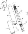
FIG. 1 is a perspective view of the lancing device according to a first embodiment of the present invention. -
FIG. 2 is a perspective view of the lancing device according to the first embodiment of the present invention showing a state in which a front cap, a sleeve, and a rear cap, which form an external appearance, are disassembled. -
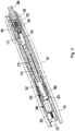
FIG. 3 is a longitudinal sectional view of the lancing device according to the first embodiment of the present invention cut out at an angle of 90 degrees. -
FIG. 4 is a longitudinal sectional view of the lancing device according to the first embodiment of the present invention. -
FIG. 5 is a longitudinal sectional view of the lancing device according to the first embodiment of the present invention in which a front cap, a sleeve, and a rear cap are omitted. -
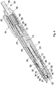
FIG. 6 is a drawing showing an internal structure of the lancing device according to the first embodiment of the present invention. -
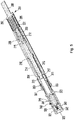
FIG. 7 is a drawing showing an operating state of a launch part. -
FIG. 8 is a cross-sectional view of a bumper part and a coupling shaft of the lancing device according to the first embodiment of the present invention, in which the bumper part is coupled with the coupling shaft. -
FIG. 9 is a drawing showing a state in which a needle body holder and a depth adjusting member of the bumper part of the lancing device according to the first embodiment of the present invention are disassembled and the needle body holder and the coupling shaft are engaged. -
FIG. 10 is an enlarged perspective view of the bumper part of the lancing device according to the first embodiment of the present invention. -
FIG. 11 is an exploded perspective view of the bumper part of the lancing device according to the first embodiment of the present invention. -
FIG. 12 is a drawing showing a state in which the depth adjusting member of the lancing device according to the first embodiment of the present invention is engaged with the needle body holder, and the needle body is inserted into a needle body hole or disassembled therefrom. -
FIG. 13 is an enlarged longitudinal sectional view of the bumper part for showing an operating state of the bumper part of the lancing device according to the first embodiment of the present invention, in whichFIG. 13 (a) illustrates a state of the lancet before launching, andFIG. 13 (b) illustrates a state in which the lancet penetrates the skin immediately after the lancet is launched. -
FIG. 14 is a perspective view of a disposable painless lancet according to a second embodiment of the present invention, in whichFIG. 14 (a) illustrates a state before use in which the bump spring is expanded, andFIG. 14 (b) illustrates a state in which the needle penetrates the skin and the bump spring is compressed. -
FIG. 15 is another perspective view of a disposable painless lancet according to the second embodiment of the present invention. -
FIG. 16 is a longitudinal sectional view of the disposable painless lancet according to the second embodiment of the present invention. -
FIG. 17 is another perspective view of the disposable painless lancet according to the second embodiment of the present invention, in which the lancet is disassembled. -
FIG. 18 is another perspective view of the disposable painless lancet according to the second embodiment of the present invention, in which a silicone or elastic member is used in place of the bump spring, in whichFIG. 18 (a) illustrates a state before use in which the silicone or elastic member is expanded, andFIG. 18 (b) illustrates a state in which the needle penetrates the skin and the silicone or elastic member is compressed. -
FIG. 19 is another perspective view of the lancing device according to the second embodiment of the present invention illustrating a state in which a front cap, a sleeve, and a rear cap, which form an external appearance, are disassembled. -
FIG. 20 is another longitudinal sectional view of the lancing device according to the second embodiment of the present invention. -
FIG. 21 is a drawing showing an internal structure of the lancing device according to the second embodiment of the present invention. -
FIG. 22 is a cross-sectional view of a holder part and a coupling shaft of the lancing device according to the second embodiment of the present invention, in which the holder part is coupled with the coupling shaft, and the lancet is mounted to the device. -
FIG. 23 is a drawing illustrating a structure in which the holder part is coupled with the coupling shaft, and the lancet is mounted to the device in accordance with the second embodiment of the present invention. -
FIG. 24 is a drawing illustrating a state in which the rectangular part, the coupling shaft and the holder part of the lancing device according to a second embodiment of the present invention are assembled. -
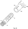
FIG. 25 is a drawing illustrating a state in which the needle body ofFIG. 24 is disassembled. -
FIG. 26 is a drawing illustrating the operation states of the bump spring and the needle of the lancing device according to the second embodiment of the present invention, in whichFIG. 26(a) illustrates a state before launching andFIG. 26(b) illustrates a state after launching. - Hereinafter, the present invention will be described in more detail with reference to the accompanying drawings. However, the contents shown in the detailed description and in the drawings do not limit the present invention.
-
FIGS. 1-13 are views of the lancing device according to a first embodiment of the present invention. - As shown in
FIGS. 1 and2 , the lancing device according to the first embodiment of the present invention includes: acasing 100 that forms an outer appearance of the device; and alaunch part 200 for launching abumper part 300 having abumper 320 and aneedle body 341 to strike the skin, in which thebumper part 300 has aneedle body holder 310 including thebumper 320 that primarily strikes the skin and aneedle spring 342 that strikes the skin secondarily. - When the
bumper part 300 is launched, thebumper part 300 first strikes the skin by the inertial force at the time of launching, and then continues to press the skin while being in contact with the skin by the compressive force of abump spring 303. At this time, thebump spring 303 is compressed due to the inertial force of thebumper 320, which is momentarily maintained, and the inertial force of theneedle body holder 310 including the lancet. Astop bar 323 seated on an upper end of thebumper 320 then moves up to a tip of an adjustingmember flange 351 to be properly adjusted along arectangular hole 313 of acylindrical body 312, and theneedle spring 342 of theneedle body 341 strikes the skin. Immediately thereafter, theneedle 343 penetrates into the subcutaneous tissue of the skin, and then theentire bumper part 300,- that is, thebumper 320, theneedle body holder 310, adepth adjusting member 350, thestop bar 323, acotter pin 325, theneedle body 341, and theneedle spring 342 are simultaneously returned to the initial position before the launch by abumper return spring 214. At this time, a penetration depth of theneedle 343 can be controlled by the vertical movement of thestop bar 323 only to the extent of the adjustment position set by the adjustingmember flange 351. -
FIG. 1 is a perspective view of a lancing device according to the first embodiment of the present invention, showing thecasing 100. As shown inFIGS. 1 and2 , thecasing 100 includes a cylindricalfront cap 101, asleeve 102 having one side coupled to thefront cap 101 and the other side coupled to arear cap 103, and therear cap 103 coupled to thesleeve 102. Thefront cap 101, thesleeve 102 and therear cap 103 are preferably screw-coupled together. Therear cap 103 may be provided with aclip 104 for convenient carrying. - As shown in
FIGS. 3-7 , thelaunch part 200 includes alaunch body 201, alaunch spring 202, alaunch pestle 203, asquare tube 204 and a launchbody return spring 205. As shown in detail inFIGS. 5-7 , thelaunch body 201 integrally comprises apush member 206, alaunch flange 207 formed at the tip of thepush member 206, and ahollow tetrahedron 208 which is open at one side to accommodate thelaunch pestle 203 and thelaunch spring 202. As shown in detail inFIG. 7 , in a lower part of thehollow tetrahedron 208, there are formedsquare holes 211 whose upper sides are sloped on one surface and the opposite surface, respectively. The upper sides of the twosquare holes 211 are opposite to each other (i.e., '\' or '/'). A launch spring 210 is inserted into one side of thelaunch pestle 203 and atrigger pin 212 is coupled through a middle part of thelaunch pestle 203. - As shown in detail in
FIGS. 4-6 , a rectangular hole (not shown) is formed in the upper part of thesquare tube 204 to insert thehollow tetrahedron 208 of thelaunch body 201, and a circular hole (not shown) is formed in the lower part of thesquare tube 204 to insert acolumnar coupling shaft 213. As shown in detail inFIGS. 6 and7 , thesquare tube 204 is configured to receive thecoupling shaft 213, thebumper return spring 214 and half of thetetrahedron 208 of thelaunch body 201. Two '┐'-shapedslits 215 are formed on one side and the opposite side of thesquare tube 204, respectively, and the twoslits 215 are formed asymmetrically. That is, one of the twotransverse slits 215 has a '┐' shape and the other has a T' shape. Theslits 215 are fitted with atrigger pin 212 to move. - A launch
body return spring 205 for returning thelaunch body 201 is interposed between the upper end of thesquare tube 204 and thelaunch flange 207. - Referring to
FIG. 7 , the operation of thelaunch part 200 will be described as follows. - Before launching, the
trigger pin 212 is positioned at the lower side of thesquare hole 211 and in the transverse slits of the '┐'-shapedslits 215. Thepush member 206 is pressed by about 10 mm to launch thebumper 320 and the needle holder 302, then the launch spring 210 connected to thelaunch pestle 203 in thehollow tetrahedron 208 is compressed. Thetrigger pin 212 passing through thelaunch pestle 203 connected to the launch spring 210 is slid along the upper side of therectangular hole 211 and is "twisted", and then is pushed along the transverse slits of the '┐'-shapedslits 215 and momentarily falls below the longitudinal slits of the '┐'-shapedslits 215, whereby thelaunch pestle 203 can be launched. When thelaunch pestle 203 is lowered to the end of the transverse slits of the '┐'-shaped slits, a launching force is transmitted to thebumper part 300 through thecoupling shaft 213, so that thebumper 320 strikes the skin. When thepush member 206 is pushed again, thelaunch body 201 and thelaunch pestle 203 return to the transverse slits of the '┐'-shapedslits 215 and return to the standing state. - As shown in
FIGS. 6 and11 , thebumper part 300 mainly includes theneedle body holder 310, thebumper 320, and thebump spring 303. - As shown in detail in
FIG. 9 , theneedle body holder 310 includes aholder flange 311 formed at its upper portion and acylindrical body 312 formed under theholder flange 311. Arectangular hole 313 is formed in thecylindrical body 312 so that thestop bar 323 moves up and down. A needlebody insertion hole 314 for inserting alancet 340 is formed in the lower portion of thecylindrical body 312. - As shown in
FIG. 11 , one side of the needlebody insertion hole 314 is opened to allow theneedle body 341 to be inserted and removed laterally, and the two inner walls of the needlebody insertion hole 314 are configured to be flat to engage with the two lateral surfaces of theneedle body 341. The lower end of thecylindrical body 312 is opened to allow theneedle 343 of thelancet 340 and theneedle spring 342 to move in and out. A needlebody fixing protrusion 316 fixed to the fixinggroove 345 of theneedle body 341 is formed on the inner walls of the needlebody insertion hole 314. As shown inFIG. 9 , a ring-shapedprotrusion 315 is formed on the upper end of theholder flange 311 toward the inside of theholder flange 311 so as to be coupled to a circular-shapedcoupling groove 217 formed along the outer peripheral surface of the lower end of thecoupling shaft 213. A screw thread for engaging with a spiral formed on the inner side of thedepth adjusting member 350 is formed on the outer peripheral surface of theholder flange 311. - As shown in
FIGS. 8 and9 , thecoupling shaft 213 has a columnar shape and has acoupling shaft flange 216 for inserting and fixing thereturn spring 214. Thecoupling groove 217 is formed at the lower end of thecoupling shaft flange 216 so as to be engaged with the ring-shapedprotrusion 315 formed toward the inside of theholder flange 311. - As shown in
FIGS. 11 and12 , a needlebody fixing protrusion 316 for fixing theneedle body 341 is formed on the inner walls of the needlebody insertion hole 314. The needlebody fixing protrusion 316 is preferably in the form of a bead of a metal or plastic material. - As shown in detail in
FIGS. 6 and11 , thebumper 320 is cylindrical, and the upper part of thebumper 320 is open to receive theneedle body holder 310 and has arectangular hole 321 for inserting and removing thelancet 340 in the longitudinal direction. Aneedle access hole 322 is formed at the lower end of thebumper 320 to allow theneedle 343 and theneedle spring 342 to move in and out. A stopbar insertion port 324 is formed in the upper end of thebumper 320 to insert thestop bar 323. As shown in detail inFIGS. 8-11 , thestop bar 323 is inserted through therectangular hole 313 and the stopbar insertion port 324 of theneedle body holder 310. The cotter pins 325 are fitted at both ends of thestop bar 323 so that thestop bar 323 is not separated from thebumper 320. - As shown in detail in
FIGS. 5 ,8 ,10 and13 , thebump spring 303 is inserted between the lower surface of theholder flange 311 of theneedle body holder 310 and the upper surface of thebumper 320 while surrounding thecylindrical body 312. - As shown in detail in
FIGS. 11-13 , thelancet 340 inserted into the lancing device according to the first embodiment of the present invention includes theneedle body 341, theneedle spring 342, and theneedle 343. Theneedle body 341 hasprotrusions 344 formed at both ends along the longitudinal direction of theneedle body 341 and is configured to be inserted in conformity with the shape of the needlebody insertion hole 314. Theneedle 343 is embedded in theneedle body 341. Fixinggrooves 345 are formed on both sides of theneedle body 341 so as to be fastened to the needlebody fixing protrusions 316 provided on the inner wall of both sides of the needlebody insertion hole 314 of theneedle body holder 310. - The
lancet 340 according to the first embodiment of the present invention is disposable and theneedle spring 342 completely surrounds theneedle 343 to prevent secondary infections such as hepatitis and AIDS caused by careless handling. - The lancing device according to the first embodiment of the present invention may be provided with a
depth adjusting member 350 to adjust the needle penetration depth since people's skin thickness is different. As shown in detail inFIGS. 4 ,5 , and13 , thedepth adjusting member 350 is cylindrical and is open at its upper and lower ends. A spiral for coupling with a screw formed on theholder flange 311 of theneedle body holder 310 is formed on the upper inner circumferential surface of thedepth adjusting member 350 and an adjustingmember flange 351 is formed at a lower end thereof. - As shown in detail in
FIGS. 3 and4 , the adjustingmember flange 351 is engaged with the screw formed in theholder flange 311 at the top of thecylindrical body 312 of theneedle body holder 310, and the penetration depth of theneedle 343 can be adjusted by turning thedepth adjusting member 350 to the left or right. When the adjustingmember flange 351 is turned to the right, theneedle 343 penetrates deeper into the skin. At this time, thestop bar 323 moves along therectangular hole 313 and the movement distance becomes longer, so that the skin penetrates deeper into the skin. On the contrary, when the adjustingmember flange 351 is turned to the left, theneedle 343 penetrates the skin more shallowly. At this time, thestop bar 323 moves along therectangular hole 313 and the movement distance becomes shorter, so that the skin penetrates the skin more shallowly. - Referring to
FIGS. 3-5 ,8 ,11 and13 , the operation of thebumper part 300 of the lancing device according to the first embodiment of the present invention will be described below. - When the
push member 206 of thelaunch part 200 is pushed to trigger thelaunch pestle 203 to strike thecoupling shaft 213, a force is transmitted to theneedle body holder 310 through the ring-shapedprotrusion 315 formed toward the inner side of thecoupling groove 217 of thecoupling shaft 213 and theholder flange 311 coupled to thecoupling groove 217. At this time, thebump spring 303 should be strong enough to transmit the launching force to thebumper 320. The lower end surface of thebumper 320 strikes the skin due to the launching force, then thebump spring 303 is compressed and theneedle spring 342 of theneedle body 341 inserted into theneedle body holder 310 strikes the skin. Immediately thereafter, theneedle 343 penetrates the subcutaneous tissue of the skin, and then theentire bumper part 300, that is, thebumper 320, theneedle spring 342 and theneedle 343 are simultaneously returned by thereturn spring 214. While thebumper 320 is striking the skin and contacting the skin, theneedle spring 342 inserted into theneedle body holder 310 strikes the skin, and then theneedle 343 penetrates the skin immediately when theneedle spring 342 is in contact with the skin. At the same time, thestop bar 323 rises along therectangular hole 313 of theneedle body holder 310 and stops to the lower end of the adjustingmember flange 351. This point is the limit that theneedle 343 penetrates the skin. At this time, the depth of penetration of theneedle 343 is adjusted by causing thestop bar 323 to perform a vertical movement only to the end of the screw adjusting position of the adjustingmember flange 351. After thebumper 320 strikes the skin, theneedle spring 342 strikes the skin again in contact with the skin. Further, after theneedle 343 pierces the skin while thebumper 320 and theneedle spring 342 are in contact with the skin, thebumper 320, theneedle spring 342, and theneedle 343 are simultaneously released from the skin by thebumper return spring 214. Theneedle spring 342 extends a little longer than theneedle 343 and is inserted or fixed to theneedle fixing protrusion 346 formed on theprotrusion 344 while surrounding theneedle 343. - As described above, since the
bumper 320 first strikes the skin, and then theneedle spring 342 strikes the skin secondarily with a time difference of about 0.1 second, theneedle 343 pierces the skin almost at the same time, and the subject will not feel any pain at all. -
FIGS. 14-26 are drawings of a disposable painless lancet and a lancing device according to a second embodiment of the present invention. - Hereinafter, the disposable painless lancet and the lancing device for therewith according to the second embodiment of the present invention will be described.
- As shown in
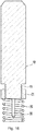
FIG. 14 , the disposable painless lancet according to the second embodiment of the present invention includes aneedle body 10, aneedle 30 embedded in the center of one end of theneedle body 10 and abump spring 20 embedded in one end of theneedle body 10 to surround theneedle 30. - The material of the
needle body 10 is preferably plastics. Theneedle body 10 may have a columnar structure, preferably a skeleton structure as shown inFIGS. 14 and15 . - The
needle 30 is embedded or fixed at the center of one end of theneedle body 10. As shown inFIG. 14 (a) , a part of thebump spring 20 is embedded or fixed to the center of one end of theneedle body 10 so as to surround theneedle 30 longer than the length of theneedle 30. - The length of the
needle 30 can be standardized in the production of the product. In the drawings attached to the present specification, the tip of theneedle 30 is conical, but may be angular. -
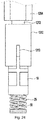
FIG. 14 (b) shows the state of the disposable painless lancet when contacted with the skin (40 inFIG. 26 ) after being launched from the lancing device for sampling blood. When the disposable painless lancet of the present invention is launched from the lancing device, thebump spring 20 momentarily strikes a skin 40. At this time, the skin 40 is first impacted by the momentary striking applied by thebump spring 20, disturbing the skin nerve not to feel the pain. After theneedle 30 has pierced the skin 40, theneedle 30 is momentarily released out of the skin 40 due to the force of restoration of thebump spring 20 and the time theneedle 30 stays on the skin is very short. Also, theneedle 30 does not penetrate excessively below the subcutaneous tissue. Thebump spring 20 is compressed by inertia at the time of launching and theneedle 30 penetrates the skin 40 while pressing the skin 40 harder and harder so that the pain is reduced or eliminated when theneedle 30 is pierced. This is like the principle that a nurse in a hospital pierces a needle immediately after striking the skin with the palm of a hand to relieve pain. - As shown in
FIG. 26 , since thebump spring 20 determines a limit of a length that can be pressed immediately after striking the skin 40 and theneedle 30 can penetrate the skin 40, theneedle 30 penetrates the skin 40 only by a predetermined length. Therefore, it is possible to prevent theneedle 30 from being excessively penetrated into the skin 40 more than necessary for sampling blood. - Also, after the
needle 30 has penetrated the skin, the blood sticks to theneedle 30 inevitably. However, since theneedle 30 is hidden in thebump spring 20, there is no fear that the blood stuck on theneedle 30 comes into contact with a person, thereby preventing secondary infections of various diseases such as AIDS and hepatitis. -
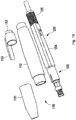
FIGS. 15-17 are views showing a disposable painless lancet having aspiral part 11 and aspring body 21, which are means for adjusting the depth of theneedle 30 into the skin 40 according to the second embodiment of the present invention. - One end of the
needle body 10 has thecolumnar spiral part 11 smaller than the diameter of theneedle body 10 and one end of theneedle 30 is embedded in the center of the end of thespiral part 11. Thespring body 21 is nut-shaped and is screwed onto thespiral part 11. A spiral is formed inside thespring body 21, and one end of thebump spring 20 is embedded or fixed to one side of thespring body 21. When thespring body 21 is turned clockwise, theneedle 30 penetrates the skin 40 deeper, and when thespring body 21 is turned counterclockwise, theneedle 30 penetrates the skin 40 more shallowly. - As shown in
FIG. 18 , in the present invention, instead of thebump spring 20, a silicone orelastic member 50 may be used for a spring function. - In the lancing device according to the second embodiment of the present invention, the principle of operation of the disposable painless lancet in which the silicone or
elastic member 50 is used in place of thebump spring 20 is the same as that of the lancet using thebump spring 20. - Further, the present invention provides a lancing device for use with the disposable painless lancet according to the second embodiment of the present invention.
- As shown in
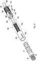
FIG. 19 , the lancing device according to the second embodiment of the present invention mainly includes acasing 1100 forming an outer appearance thereof, alaunch part 1200 for launching theneedle body 10 in aneedle body holder 1300, in which theneedle body holder 1300 is configured for holding and fixing theneedle body 10. - As shown in
FIG. 19 , thecasing 1100 includes afront cap 1101, asleeve 1102 having one end coupled to thefront cap 1101 and the other end coupled to therear cap 1103, in which therear cap 1103 is coupled to thesleeve 1102. Thefront cap 1101, thesleeve 1102, and therear cap 1103 are preferably screwed together. Therear cap 1103 may be provided with aclip 1104 for convenient carrying. - As shown in
FIGS. 20 and21 , thelaunch part 1200 includes alaunch body 1201, alaunch spring 1202, alaunch pestle 1203, asquare tube 1204, and a launchbody return spring 1205. As shown in detail inFIGS. 19-21 , thelaunch body 1201 integrally comprises apush member 1206, alaunch flange 1207 formed at the tip of thepush member 1206, and ahollow tetrahedron 1208 which is open at one side to accommodate thelaunch pestle 1203 and thelaunch spring 1202. As shown in detail inFIG. 21 , in the lower part of thehollow tetrahedron 1208, there are formedsquare holes 1211 whose upper sides are sloped on one surface and the opposite surface, respectively. The upper sides of the twosquare holes 1211 are opposite to each other i.e., '\' or '/'). A launch spring 1210 is inserted into one side of thelaunch pestle 1203 and atrigger pin 1212 is coupled through the middle part of thelaunch pestle 1203. - In the lancing device according to the second embodiment of the present invention, the structure and operation principle of the
launch part 1200 are as described above with reference toFIGS. 3-7 of the lancing device according to the first embodiment of the present invention. - As shown in detail in
FIGS. 20 and21 , a ring-shapedprotrusion 1315 is formed in the upper position of theneedle body holder 1300 so as to be engaged with acoupling groove 1217 of acoupling shaft 1213. Theneedle body holder 1300 is open at its lower portion and has oneincision groove 1313 cut from the lower portion to the middle portion thereof. Theincision groove 1313 is configured to elastically hold theneedle body 10 firmly. - As shown in
FIG. 20 , thefront cap 1101 of thecasing 1100 has a shape gradually tapering from the top to the bottom. Acircular engagement protrusion 1105 is formed on the inside of thefront cap 1101 to limit the downward movement of the lower surface of acylindrical body 1312. Aguide hole 1106 is formed from theengagement protrusion 1105 to the lower end of thefront cap 1101 to guide theneedle body 10 and thebump spring 20 in a predetermined direction. - Referring to
FIGS. 20 and21 , the operation of theneedle body holder 1300 of the lancing device and the disposable painless lancet according to the second embodiment of the present invention will be described below. - When the
push member 1206 of thelaunch part 1200 is pushed to trigger thelaunch pestle 1203 to strike thecoupling shaft 1213, a force is transmitted to the needle body holder 1310 through the ring-shapedprotrusion 1315 formed toward the inner side of thecoupling groove 1217 of thecoupling shaft 1213 and thecylindrical body 1312 coupled to thecoupling groove 1217. The force is then transmitted to the lancet including theneedle body 10 inserted in thecylindrical body 1312, thebump spring 20 and theneedle 30. Then, theneedle body 10 of the lancet and thebump spring 20 are guided through theguide hole 1106 and then thebump spring 20 strikes the skin. Theneedle 30 penetrates into the capillary blood vessels of the skin while thebump spring 20 is compressed, and then thecylindrical body 1312 of theneedle body holder 1300 and the whole lancet are simultaneously returned to the position before the launching by thebump spring 20. - As described above, since the
bump spring 20 strikes the skin to disturb the skin nerves, and then theneedle 30 pierces the skin with a slight difference in time, and the time during which theneedle 30 stays in the skin 40 is significantly shortened by the restoring force of thebump spring 20, thereby completely eliminating the pain. - According to the second embodiment of the present invention, when the disposable painless lancet having the silicone or
elastic member 50 in place of thebump spring 20 is inserted in the lancing device, the operation principle of the lancing device is the same as the principle described in connection with thebump spring 20. - The present inventors conducted an experiment for painlessness by use of the lancing device according to the present invention in 50 adult males (mean age 42.5 years). The disposable painless lancets were launched on the skin of their ring fingers. Blood flowed a little, but all 50 people could not feel the pain.
- The present invention may also be defined by means of the following numbered clauses.
- 1. A painless lancing device comprising.
a casing including:- a cylindrical front cap;
- a sleeve connected to the cylindrical front cap at a lower end; and
- a rear cap connected to an upper end of the sleeve;
a bumper part disposed in the casing and connected to the launch part by a coupling shaft,
wherein the bumper part comprises a needle body holder including:- a holder flange disposed at an upper portion thereof;
- a first rectangular hole disposed below the holder flange so that a stop bar moves up and down; and
- a needle body insertion hole disposed at a lower portion of the bumper part to insert a lancet;
- a second rectangular hole disposed along a longitudinal direction to insert and remove the lancet;
- a needle access hole disposed at a lower end of the cylindrical bumper for a needle and a needle spring to move in and out therethrough; and
- a stop bar insertion port disposed at the upper end to insert the stop bar; and
- 2. The painless lancing device according to
Clause 1, wherein one side of the needle body insertion hole is configured to allow insertion and removal of the needle body from said one side, and the needle body is disposed to align and fit within the needle body insertion hole. - 3. The painless lancing device according to
Clause 1, wherein the cylindrical body has a lower end configured to allow the needle of the lancet and the needle spring to move in and out,
wherein a ring-shaped protrusion is disposed at an inside surface of an upper end of the holder flange so that the ring-shaped protrusion is engaged with a circular-shaped coupling groove disposed along a lower outer peripheral surface of the coupling shaft, and
wherein the holder flange has a screw thread disposed on an outer circumferential surface thereof for screw coupling with a spiral disposed on an inside surface of a depth adjusting member. - 4. The painless lancing device according to
Clause 1, wherein inner surfaces of the needle body holder have a plurality of needle body fixing protrusions for fixing the needle body. - 5. The painless lancing device according to
Clause 4, wherein the lancet further comprises:- a rectangular needle body;
- an upper protrusion and a lower protrusion disposed on an upper side and a lower side of the needle body, respectively, wherein a needle fixing protrusion is disposed on the lower protrusion, the needle spring is inserted and fixed on the needle fixing protrusion, and the needle is inserted into the needle body through the needle fixing protrusion; and
- a plurality of fixing grooves to be fixed on the plurality of needle body fixing protrusions provided on the inner surfaces of the needle body holder.
- 6. The painless lancing device according to
Clause 1, further comprising a depth adjusting member configured to adjust a depth of skin penetration of the needle and having an open upper end and an open lower end, the depth adjusting member comprising:- a spiral disposed in an inner surface thereof for engaging with a screw thread disposed on an outer circumferential surface of the holder flange of the cylindrical body of the needle body holder; and
- an adjusting member flange disposed at a lower end of the depth adjusting member.
- 7. The painless lancing device according to
Clause 1, wherein the bumper part is connected to the coupling shaft by engaging a ring-shaped protrusion disposed at an inside surface of an upper end of the holder flange with a circular-shaped coupling groove disposed along a lower outer peripheral surface of the coupling shaft, the coupling shaft comprising a coupling shaft flange for inserting a return spring therein. - 8. A disposable painless lancet comprising:
- a needle body;
- a needle embedded at a center of one end of the needle body; and
- a bump spring embedded or fixed at said one end of the needle body so as to surround the needle and extend beyond the needle.
- 9. The disposable painless lancet according to Clause 8,
wherein the needle body comprises an elongated spiral part disposed at one end thereof; and an end of the needle is embedded in a center of an end of the elongated spiral part,
wherein a spring body having a screw thread disposed in an inner surface thereof is screw coupled with the elongated spiral part, and
wherein one end of the bump spring is embedded or fixed to the spring body. - 10. The disposable painless lancet according to Clause 8 or 9, comprising a silicone or elastic member instead of the bump spring.
- 11. A painless lancing device, comprising:
- a casing including:
- a cylindrical front cap;
- a sleeve connected to the cylindrical front cap at a bottom end; and
- a rear cap connected to a top end of the sleeve;
- a launch part for launching a needle body disposed inside a cylindrical body; and
- a needle body holder for holding and fixing the needle body ,
- wherein the cylindrical front cap has a gradually tapering shape from a top end to a bottom end, and the cylindrical front cap comprises:
- a circular engagement protrusion disposed on an inside surface of the cylindrical front cap to limit a downward movement of a bottom surface of the cylindrical body; and
- a guide hole provided from the circular engagement protrusion to the bottom end of the cylindrical front cap to guide the needle body and a bump spring in a predetermined direction,
- wherein the needle body holder comprises a ring-shaped protrusion disposed in an inside surface of the needle body holder so as to be engaged with a coupling groove of a coupling shaft, and
- wherein the needle body holder is open at a bottom portion and has one incision groove on its side provided from the lower portion to a middle portion thereof.
- a casing including:
Claims (3)
- A disposable painless lancet comprising:a needle body 10;a needle 30 embedded at a center of one end of the needle body 10; anda bump spring 20 embedded or fixed at said one end of the needle body 10 so as to surround the needle 30 and extend beyond the needle 30.
- The disposable painless lancet according to Claim 1,
wherein the needle body 10 comprises an elongated spiral part 11 disposed at one end thereof; and an end of the needle 30 is embedded in a center of an end of the elongated spiral part 11,
wherein a spring body 21 having a screw thread disposed in an inner surface thereof is screw coupled with the elongated spiral part 11, and
wherein one end of the bump spring 20 is embedded or fixed to the spring body 21. - The disposable painless lancet according to Claim 1 or 2, comprising a silicone or elastic member 50 instead of the bump spring 20.
Applications Claiming Priority (5)
| Application Number | Priority Date | Filing Date | Title |
|---|---|---|---|
| KR20160053935 | 2016-05-02 | ||
| KR1020160085674A KR101731340B1 (en) | 2016-07-06 | 2016-07-06 | Pain-Free Lancet Device |
| KR1020170036096A KR101851212B1 (en) | 2016-05-02 | 2017-03-22 | Disposable Pain-Free Lancet And Device For Taking A Blood Sample |
| PCT/KR2017/004661 WO2017191985A2 (en) | 2016-05-02 | 2017-05-02 | Disposable painless lancet and lancing device |
| EP17792887.6A EP3453325A4 (en) | 2016-05-02 | 2017-05-02 | Disposable painless lancet and lancing device |
Related Parent Applications (1)
| Application Number | Title | Priority Date | Filing Date |
|---|---|---|---|
| EP17792887.6A Division EP3453325A4 (en) | 2016-05-02 | 2017-05-02 | Disposable painless lancet and lancing device |
Publications (2)
| Publication Number | Publication Date |
|---|---|
| EP3834724A2 true EP3834724A2 (en) | 2021-06-16 |
| EP3834724A3 EP3834724A3 (en) | 2021-06-23 |
Family
ID=64565303
Family Applications (2)
| Application Number | Title | Priority Date | Filing Date |
|---|---|---|---|
| EP17792887.6A Withdrawn EP3453325A4 (en) | 2016-05-02 | 2017-05-02 | Disposable painless lancet and lancing device |
| EP21150771.0A Withdrawn EP3834724A3 (en) | 2016-05-02 | 2017-05-02 | Disposable painless lancet and lancing devices for use therewith |
Family Applications Before (1)
| Application Number | Title | Priority Date | Filing Date |
|---|---|---|---|
| EP17792887.6A Withdrawn EP3453325A4 (en) | 2016-05-02 | 2017-05-02 | Disposable painless lancet and lancing device |
Country Status (11)
| Country | Link |
|---|---|
| US (1) | US20190142321A1 (en) |
| EP (2) | EP3453325A4 (en) |
| JP (1) | JP2019519274A (en) |
| CN (1) | CN109310379A (en) |
| AU (1) | AU2017260474A1 (en) |
| CA (1) | CA3028349A1 (en) |
| IL (1) | IL262760A (en) |
| PH (1) | PH12018502326A1 (en) |
| RU (1) | RU2717636C1 (en) |
| SG (1) | SG11201809730SA (en) |
| ZA (1) | ZA201808138B (en) |
Families Citing this family (2)
| Publication number | Priority date | Publication date | Assignee | Title |
|---|---|---|---|---|
| CN113069355B (en) * | 2020-01-03 | 2022-07-12 | 高谦 | Intelligent internal hot needle punching machine |
| CN113384304B (en) * | 2021-07-13 | 2022-05-13 | 南通市肿瘤医院 | Safe type sampling device for medical oncology |
Citations (3)
| Publication number | Priority date | Publication date | Assignee | Title |
|---|---|---|---|---|
| KR100912202B1 (en) | 2008-07-03 | 2009-08-14 | (주)보성메디텍 | One body lancet and no pain type blood collecting device |
| KR100932946B1 (en) | 2008-03-19 | 2009-12-21 | 홍관호 | Blood collector |
| KR101360939B1 (en) | 2013-10-11 | 2014-02-11 | 김광일 | Needle length variable lancet with pain and infection and danger preventing function |
Family Cites Families (21)
| Publication number | Priority date | Publication date | Assignee | Title |
|---|---|---|---|---|
| JPH0638908U (en) * | 1992-10-27 | 1994-05-24 | 株式会社メイテック | Blood collection needle |
| WO1997004707A1 (en) * | 1995-07-28 | 1997-02-13 | Apls Co., Ltd. | Assembly for adjusting piercing depth of lancet |
| DE69739783D1 (en) * | 1996-05-17 | 2010-04-08 | Roche Diagnostics Operations | DEVICE FOR SAMPLING BODY FLUIDS |
| CN1222064A (en) * | 1996-05-17 | 1999-07-07 | 莫克里诊断公司 | Methods and appts. for expressing body fluid from incision |
| GB9919681D0 (en) * | 1999-08-19 | 1999-10-20 | Owen Mumsford Limited | Improvements relating to medical injectors and skin prickers |
| JP4359671B2 (en) * | 1999-09-29 | 2009-11-04 | アークレイ株式会社 | Body fluid collection tool |
| JP2003225227A (en) * | 2002-01-31 | 2003-08-12 | Yamatake Corp | Collecting container, collecting device and collecting method |
| EP1535572A1 (en) * | 2002-09-05 | 2005-06-01 | Matsushita Electric Industrial Co., Ltd. | Invasive appliance |
| US8211036B2 (en) * | 2005-05-27 | 2012-07-03 | Stat Medical Devices, Inc. | Disposable lancet device cap with integral lancet and/or test strip and testing device utilizing the cap |
| US20070078474A1 (en) * | 2005-10-05 | 2007-04-05 | Kim Yong P | Single-use lancet device |
| EP1785090A1 (en) * | 2005-11-10 | 2007-05-16 | F.Hoffmann-La Roche Ag | Lancet device and system for skin detection |
| WO2008023703A1 (en) * | 2006-08-22 | 2008-02-28 | Sumitomo Electric Industries, Ltd. | Biosensor cartridge |
| JP4957121B2 (en) * | 2006-08-22 | 2012-06-20 | 住友電気工業株式会社 | Biosensor cartridge |
| KR20100120403A (en) * | 2009-05-06 | 2010-11-16 | 신병섭 | Lancing device |
| EP2613701A2 (en) * | 2010-09-07 | 2013-07-17 | Innova Medical Design LLC | Systems, methods, and devices for reducing the pain of glucose monitoring and insulin adminstration in diabetic patients |
| CN102028480B (en) * | 2010-12-21 | 2012-02-15 | 苏州施莱医疗器械有限公司 | Improved safe and convenient disposable automatic blood taking needle |
| CN201977801U (en) * | 2011-01-06 | 2011-09-21 | 庄彩梅 | Blood taking needle |
| CN102379704B (en) * | 2011-08-24 | 2013-05-15 | 苏州生物医学工程技术研究所 | Blood sampler with adjustable puncture depth |
| JP5836399B2 (en) * | 2011-12-26 | 2015-12-24 | パナソニックヘルスケアホールディングス株式会社 | Liquid sample measuring device |
| CN203122421U (en) * | 2013-03-08 | 2013-08-14 | 梁桂娟 | Adjustable blood taking needle |
| CN105455824A (en) * | 2014-09-09 | 2016-04-06 | 大捷达实业(深圳)有限公司 | Painless vacuum blood collector |
-
2017
- 2017-05-02 EP EP17792887.6A patent/EP3453325A4/en not_active Withdrawn
- 2017-05-02 CN CN201780027233.2A patent/CN109310379A/en active Pending
- 2017-05-02 AU AU2017260474A patent/AU2017260474A1/en not_active Abandoned
- 2017-05-02 EP EP21150771.0A patent/EP3834724A3/en not_active Withdrawn
- 2017-05-02 JP JP2018558123A patent/JP2019519274A/en active Pending
- 2017-05-02 RU RU2018142232A patent/RU2717636C1/en active
- 2017-05-02 CA CA3028349A patent/CA3028349A1/en not_active Abandoned
- 2017-05-02 US US16/097,871 patent/US20190142321A1/en not_active Abandoned
- 2017-05-02 SG SG11201809730SA patent/SG11201809730SA/en unknown
-
2018
- 2018-11-04 IL IL262760A patent/IL262760A/en unknown
- 2018-11-05 PH PH12018502326A patent/PH12018502326A1/en unknown
- 2018-11-30 ZA ZA2018/08138A patent/ZA201808138B/en unknown
Patent Citations (3)
| Publication number | Priority date | Publication date | Assignee | Title |
|---|---|---|---|---|
| KR100932946B1 (en) | 2008-03-19 | 2009-12-21 | 홍관호 | Blood collector |
| KR100912202B1 (en) | 2008-07-03 | 2009-08-14 | (주)보성메디텍 | One body lancet and no pain type blood collecting device |
| KR101360939B1 (en) | 2013-10-11 | 2014-02-11 | 김광일 | Needle length variable lancet with pain and infection and danger preventing function |
Also Published As
| Publication number | Publication date |
|---|---|
| US20190142321A1 (en) | 2019-05-16 |
| CN109310379A (en) | 2019-02-05 |
| RU2717636C1 (en) | 2020-03-24 |
| JP2019519274A (en) | 2019-07-11 |
| ZA201808138B (en) | 2020-05-27 |
| AU2017260474A1 (en) | 2018-12-13 |
| IL262760A (en) | 2018-12-31 |
| SG11201809730SA (en) | 2018-12-28 |
| EP3834724A3 (en) | 2021-06-23 |
| EP3453325A4 (en) | 2019-12-25 |
| CA3028349A1 (en) | 2017-11-09 |
| PH12018502326A1 (en) | 2019-09-09 |
| EP3453325A2 (en) | 2019-03-13 |
Similar Documents
| Publication | Publication Date | Title |
|---|---|---|
| KR101851212B1 (en) | Disposable Pain-Free Lancet And Device For Taking A Blood Sample | |
| US4677979A (en) | Lancet | |
| US5611809A (en) | Needle devices for medical use | |
| US5540709A (en) | Lancet device | |
| US6283982B1 (en) | Lancing device and method of sample collection | |
| US20130245497A1 (en) | Confuser crown skin pricker | |
| US20060184189A1 (en) | Cap for a dermal tissue lancing device | |
| JPS61170436A (en) | Lancet assembly | |
| HU219921B (en) | Device for making blood test, especially from fingers | |
| US10682085B2 (en) | Lancet device with first-drop removal | |
| KR20110096147A (en) | A lancing device | |
| KR101731340B1 (en) | Pain-Free Lancet Device | |
| EP3834724A2 (en) | Disposable painless lancet and lancing devices for use therewith | |
| JP7100875B2 (en) | Auxiliary tool for intradermal injection | |
| US20110040316A1 (en) | Method and Apparatus for a Single Handed Squeeze Lancet | |
| EP2653099B1 (en) | Lancet device capable of lancet detachment | |
| JP5015699B2 (en) | Puncture device | |
| KR102420411B1 (en) | Single-use safety lancet | |
| JP2014200477A (en) | Puncture tool | |
| MXPA98004004A (en) | Device for taking fluid samples corpora |
Legal Events
| Date | Code | Title | Description |
|---|---|---|---|
| PUAI | Public reference made under article 153(3) epc to a published international application that has entered the european phase |
Free format text: ORIGINAL CODE: 0009012 |
|
| STAA | Information on the status of an ep patent application or granted ep patent |
Free format text: STATUS: THE APPLICATION HAS BEEN PUBLISHED |
|
| PUAL | Search report despatched |
Free format text: ORIGINAL CODE: 0009013 |
|
| AC | Divisional application: reference to earlier application |
Ref document number: 3453325 Country of ref document: EP Kind code of ref document: P |
|
| AK | Designated contracting states |
Kind code of ref document: A2 Designated state(s): AL AT BE BG CH CY CZ DE DK EE ES FI FR GB GR HR HU IE IS IT LI LT LU LV MC MK MT NL NO PL PT RO RS SE SI SK SM TR |
|
| AK | Designated contracting states |
Kind code of ref document: A3 Designated state(s): AL AT BE BG CH CY CZ DE DK EE ES FI FR GB GR HR HU IE IS IT LI LT LU LV MC MK MT NL NO PL PT RO RS SE SI SK SM TR |
|
| RIC1 | Information provided on ipc code assigned before grant |
Ipc: A61B 5/151 20060101AFI20210517BHEP Ipc: A61B 5/15 20060101ALI20210517BHEP |
|
| STAA | Information on the status of an ep patent application or granted ep patent |
Free format text: STATUS: THE APPLICATION IS DEEMED TO BE WITHDRAWN |
|
| 18D | Application deemed to be withdrawn |
Effective date: 20211201 |