EP3822645A1 - System and method for detecting failures in a battery management system for a vehicle battery - Google Patents
System and method for detecting failures in a battery management system for a vehicle battery Download PDFInfo
- Publication number
- EP3822645A1 EP3822645A1 EP19209709.5A EP19209709A EP3822645A1 EP 3822645 A1 EP3822645 A1 EP 3822645A1 EP 19209709 A EP19209709 A EP 19209709A EP 3822645 A1 EP3822645 A1 EP 3822645A1
- Authority
- EP
- European Patent Office
- Prior art keywords
- cell
- balancing time
- cells
- battery
- cell balancing
- Prior art date
- Legal status (The legal status is an assumption and is not a legal conclusion. Google has not performed a legal analysis and makes no representation as to the accuracy of the status listed.)
- Granted
Links
- 238000000034 method Methods 0.000 title claims abstract description 41
- 239000003990 capacitor Substances 0.000 claims description 22
- 238000012544 monitoring process Methods 0.000 description 6
- 230000004048 modification Effects 0.000 description 3
- 238000004590 computer program Methods 0.000 description 2
- 238000005259 measurement Methods 0.000 description 2
- 238000012986 modification Methods 0.000 description 2
- 230000004075 alteration Effects 0.000 description 1
- 230000015556 catabolic process Effects 0.000 description 1
- 238000006731 degradation reaction Methods 0.000 description 1
- 230000001419 dependent effect Effects 0.000 description 1
- 238000001514 detection method Methods 0.000 description 1
- 238000011161 development Methods 0.000 description 1
- 238000007599 discharging Methods 0.000 description 1
- 238000010438 heat treatment Methods 0.000 description 1
- 230000001788 irregular Effects 0.000 description 1
- 230000001960 triggered effect Effects 0.000 description 1
Images


Classifications
-
- B—PERFORMING OPERATIONS; TRANSPORTING
- B60—VEHICLES IN GENERAL
- B60L—PROPULSION OF ELECTRICALLY-PROPELLED VEHICLES; SUPPLYING ELECTRIC POWER FOR AUXILIARY EQUIPMENT OF ELECTRICALLY-PROPELLED VEHICLES; ELECTRODYNAMIC BRAKE SYSTEMS FOR VEHICLES IN GENERAL; MAGNETIC SUSPENSION OR LEVITATION FOR VEHICLES; MONITORING OPERATING VARIABLES OF ELECTRICALLY-PROPELLED VEHICLES; ELECTRIC SAFETY DEVICES FOR ELECTRICALLY-PROPELLED VEHICLES
- B60L3/00—Electric devices on electrically-propelled vehicles for safety purposes; Monitoring operating variables, e.g. speed, deceleration or energy consumption
- B60L3/0023—Detecting, eliminating, remedying or compensating for drive train abnormalities, e.g. failures within the drive train
- B60L3/0046—Detecting, eliminating, remedying or compensating for drive train abnormalities, e.g. failures within the drive train relating to electric energy storage systems, e.g. batteries or capacitors
-
- G—PHYSICS
- G01—MEASURING; TESTING
- G01R—MEASURING ELECTRIC VARIABLES; MEASURING MAGNETIC VARIABLES
- G01R31/00—Arrangements for testing electric properties; Arrangements for locating electric faults; Arrangements for electrical testing characterised by what is being tested not provided for elsewhere
- G01R31/36—Arrangements for testing, measuring or monitoring the electrical condition of accumulators or electric batteries, e.g. capacity or state of charge [SoC]
- G01R31/367—Software therefor, e.g. for battery testing using modelling or look-up tables
-
- B—PERFORMING OPERATIONS; TRANSPORTING
- B60—VEHICLES IN GENERAL
- B60L—PROPULSION OF ELECTRICALLY-PROPELLED VEHICLES; SUPPLYING ELECTRIC POWER FOR AUXILIARY EQUIPMENT OF ELECTRICALLY-PROPELLED VEHICLES; ELECTRODYNAMIC BRAKE SYSTEMS FOR VEHICLES IN GENERAL; MAGNETIC SUSPENSION OR LEVITATION FOR VEHICLES; MONITORING OPERATING VARIABLES OF ELECTRICALLY-PROPELLED VEHICLES; ELECTRIC SAFETY DEVICES FOR ELECTRICALLY-PROPELLED VEHICLES
- B60L58/00—Methods or circuit arrangements for monitoring or controlling batteries or fuel cells, specially adapted for electric vehicles
- B60L58/10—Methods or circuit arrangements for monitoring or controlling batteries or fuel cells, specially adapted for electric vehicles for monitoring or controlling batteries
- B60L58/12—Methods or circuit arrangements for monitoring or controlling batteries or fuel cells, specially adapted for electric vehicles for monitoring or controlling batteries responding to state of charge [SoC]
-
- B—PERFORMING OPERATIONS; TRANSPORTING
- B60—VEHICLES IN GENERAL
- B60L—PROPULSION OF ELECTRICALLY-PROPELLED VEHICLES; SUPPLYING ELECTRIC POWER FOR AUXILIARY EQUIPMENT OF ELECTRICALLY-PROPELLED VEHICLES; ELECTRODYNAMIC BRAKE SYSTEMS FOR VEHICLES IN GENERAL; MAGNETIC SUSPENSION OR LEVITATION FOR VEHICLES; MONITORING OPERATING VARIABLES OF ELECTRICALLY-PROPELLED VEHICLES; ELECTRIC SAFETY DEVICES FOR ELECTRICALLY-PROPELLED VEHICLES
- B60L58/00—Methods or circuit arrangements for monitoring or controlling batteries or fuel cells, specially adapted for electric vehicles
- B60L58/10—Methods or circuit arrangements for monitoring or controlling batteries or fuel cells, specially adapted for electric vehicles for monitoring or controlling batteries
- B60L58/18—Methods or circuit arrangements for monitoring or controlling batteries or fuel cells, specially adapted for electric vehicles for monitoring or controlling batteries of two or more battery modules
- B60L58/22—Balancing the charge of battery modules
-
- G—PHYSICS
- G01—MEASURING; TESTING
- G01R—MEASURING ELECTRIC VARIABLES; MEASURING MAGNETIC VARIABLES
- G01R19/00—Arrangements for measuring currents or voltages or for indicating presence or sign thereof
- G01R19/165—Indicating that current or voltage is either above or below a predetermined value or within or outside a predetermined range of values
-
- G—PHYSICS
- G01—MEASURING; TESTING
- G01R—MEASURING ELECTRIC VARIABLES; MEASURING MAGNETIC VARIABLES
- G01R31/00—Arrangements for testing electric properties; Arrangements for locating electric faults; Arrangements for electrical testing characterised by what is being tested not provided for elsewhere
- G01R31/005—Testing of electric installations on transport means
- G01R31/006—Testing of electric installations on transport means on road vehicles, e.g. automobiles or trucks
-
- G—PHYSICS
- G01—MEASURING; TESTING
- G01R—MEASURING ELECTRIC VARIABLES; MEASURING MAGNETIC VARIABLES
- G01R31/00—Arrangements for testing electric properties; Arrangements for locating electric faults; Arrangements for electrical testing characterised by what is being tested not provided for elsewhere
- G01R31/28—Testing of electronic circuits, e.g. by signal tracer
- G01R31/282—Testing of electronic circuits specially adapted for particular applications not provided for elsewhere
-
- G—PHYSICS
- G01—MEASURING; TESTING
- G01R—MEASURING ELECTRIC VARIABLES; MEASURING MAGNETIC VARIABLES
- G01R31/00—Arrangements for testing electric properties; Arrangements for locating electric faults; Arrangements for electrical testing characterised by what is being tested not provided for elsewhere
- G01R31/36—Arrangements for testing, measuring or monitoring the electrical condition of accumulators or electric batteries, e.g. capacity or state of charge [SoC]
- G01R31/385—Arrangements for measuring battery or accumulator variables
- G01R31/387—Determining ampere-hour charge capacity or SoC
- G01R31/388—Determining ampere-hour charge capacity or SoC involving voltage measurements
-
- G—PHYSICS
- G01—MEASURING; TESTING
- G01R—MEASURING ELECTRIC VARIABLES; MEASURING MAGNETIC VARIABLES
- G01R31/00—Arrangements for testing electric properties; Arrangements for locating electric faults; Arrangements for electrical testing characterised by what is being tested not provided for elsewhere
- G01R31/36—Arrangements for testing, measuring or monitoring the electrical condition of accumulators or electric batteries, e.g. capacity or state of charge [SoC]
- G01R31/396—Acquisition or processing of data for testing or for monitoring individual cells or groups of cells within a battery
-
- G—PHYSICS
- G01—MEASURING; TESTING
- G01R—MEASURING ELECTRIC VARIABLES; MEASURING MAGNETIC VARIABLES
- G01R35/00—Testing or calibrating of apparatus covered by the other groups of this subclass
-
- H—ELECTRICITY
- H01—ELECTRIC ELEMENTS
- H01M—PROCESSES OR MEANS, e.g. BATTERIES, FOR THE DIRECT CONVERSION OF CHEMICAL ENERGY INTO ELECTRICAL ENERGY
- H01M10/00—Secondary cells; Manufacture thereof
- H01M10/42—Methods or arrangements for servicing or maintenance of secondary cells or secondary half-cells
- H01M10/425—Structural combination with electronic components, e.g. electronic circuits integrated to the outside of the casing
-
- H—ELECTRICITY
- H01—ELECTRIC ELEMENTS
- H01M—PROCESSES OR MEANS, e.g. BATTERIES, FOR THE DIRECT CONVERSION OF CHEMICAL ENERGY INTO ELECTRICAL ENERGY
- H01M10/00—Secondary cells; Manufacture thereof
- H01M10/42—Methods or arrangements for servicing or maintenance of secondary cells or secondary half-cells
- H01M10/48—Accumulators combined with arrangements for measuring, testing or indicating the condition of cells, e.g. the level or density of the electrolyte
- H01M10/482—Accumulators combined with arrangements for measuring, testing or indicating the condition of cells, e.g. the level or density of the electrolyte for several batteries or cells simultaneously or sequentially
-
- H—ELECTRICITY
- H02—GENERATION; CONVERSION OR DISTRIBUTION OF ELECTRIC POWER
- H02J—CIRCUIT ARRANGEMENTS OR SYSTEMS FOR SUPPLYING OR DISTRIBUTING ELECTRIC POWER; SYSTEMS FOR STORING ELECTRIC ENERGY
- H02J7/00—Circuit arrangements for charging or depolarising batteries or for supplying loads from batteries
- H02J7/0013—Circuit arrangements for charging or depolarising batteries or for supplying loads from batteries acting upon several batteries simultaneously or sequentially
- H02J7/0014—Circuits for equalisation of charge between batteries
- H02J7/0016—Circuits for equalisation of charge between batteries using shunting, discharge or bypass circuits
-
- H—ELECTRICITY
- H02—GENERATION; CONVERSION OR DISTRIBUTION OF ELECTRIC POWER
- H02J—CIRCUIT ARRANGEMENTS OR SYSTEMS FOR SUPPLYING OR DISTRIBUTING ELECTRIC POWER; SYSTEMS FOR STORING ELECTRIC ENERGY
- H02J7/00—Circuit arrangements for charging or depolarising batteries or for supplying loads from batteries
- H02J7/0047—Circuit arrangements for charging or depolarising batteries or for supplying loads from batteries with monitoring or indicating devices or circuits
-
- B—PERFORMING OPERATIONS; TRANSPORTING
- B60—VEHICLES IN GENERAL
- B60L—PROPULSION OF ELECTRICALLY-PROPELLED VEHICLES; SUPPLYING ELECTRIC POWER FOR AUXILIARY EQUIPMENT OF ELECTRICALLY-PROPELLED VEHICLES; ELECTRODYNAMIC BRAKE SYSTEMS FOR VEHICLES IN GENERAL; MAGNETIC SUSPENSION OR LEVITATION FOR VEHICLES; MONITORING OPERATING VARIABLES OF ELECTRICALLY-PROPELLED VEHICLES; ELECTRIC SAFETY DEVICES FOR ELECTRICALLY-PROPELLED VEHICLES
- B60L2240/00—Control parameters of input or output; Target parameters
- B60L2240/40—Drive Train control parameters
- B60L2240/54—Drive Train control parameters related to batteries
- B60L2240/547—Voltage
-
- H—ELECTRICITY
- H01—ELECTRIC ELEMENTS
- H01M—PROCESSES OR MEANS, e.g. BATTERIES, FOR THE DIRECT CONVERSION OF CHEMICAL ENERGY INTO ELECTRICAL ENERGY
- H01M10/00—Secondary cells; Manufacture thereof
- H01M10/42—Methods or arrangements for servicing or maintenance of secondary cells or secondary half-cells
- H01M10/425—Structural combination with electronic components, e.g. electronic circuits integrated to the outside of the casing
- H01M2010/4271—Battery management systems including electronic circuits, e.g. control of current or voltage to keep battery in healthy state, cell balancing
-
- H—ELECTRICITY
- H01—ELECTRIC ELEMENTS
- H01M—PROCESSES OR MEANS, e.g. BATTERIES, FOR THE DIRECT CONVERSION OF CHEMICAL ENERGY INTO ELECTRICAL ENERGY
- H01M2220/00—Batteries for particular applications
- H01M2220/20—Batteries in motive systems, e.g. vehicle, ship, plane
Definitions
- the present disclosure relates to a system and method for detecting failures in a battery circuit for a vehicle battery.
- the disclosure relates to a method and system for detecting component failure in a cell measuring circuit in a battery comprising a plurality of battery cells.
- Battery cell monitoring and cell balancing is typically performed by dedicated cell monitoring/measuring circuitry.
- dedicated cell monitoring/measuring circuitry To fulfil the required safety levels, such circuitry needs to consist of components having very low failure rates, which may require expensive components, and/or the inclusion of other safety measures such as redundancy, potentially making the cell monitoring system more costly and complicated.
- Some known failure modes in control circuitry for a vehicle high-voltage battery may for example lead to cell overcharging which in turn may lead to a thermal event.
- the disclosed subject matter relates to a method and system for detecting failures in a cell measuring circuit for a vehicle battery comprising a plurality of battery cells.
- First the method comprises determining a cell voltage of each of the plurality of cells by the respective cell measuring circuit.
- the method comprises performing cell balancing to balance a cell voltage for the plurality of cells and the cell balancing times are compared to determine if there are deviating cell balancing times, and if there is an identifiable pattern in the cell balancing times which can provide an indication of a failure in any of the cell measuring circuits.
- the described method further comprises detecting a first cell having a cell balancing time being lower than an average cell balancing time for the plurality of cells; detecting that at least one cell adjacent to the first cell have a cell balancing time higher than the average cell balancing time for the plurality of cells; and if the difference in cell balancing time between the first cell and the at least one adjacent cell is higher than a predetermined balancing time threshold value, determining that the cell measuring circuit for the first cell is faulty.
- An advantage of the described method is that it can detect failures that would not be detectable by only monitoring the cell voltage.
- the balancing function will aim to balance the cells so that the cell voltage will be the same for all cells. If failure was to occur suddenly and is sufficiently large, the failure would be seen in the cell voltage. However, at a later point in time, the failure would not be seen be seen in the cell voltage but only in cell balancing time since the cell balancing function evens out the cell voltages. Furthermore, if the failure is a slow degradation of the component, then the failure cannot be distinguished from a normal deviation and the cell will slowly be balanced to keep the voltage difference low. Over time the error in the measurement due to a faulty cell measurement circuit will be big but it will not be detected when measuring the cell voltages, but it will be seen on the balancing time.
- the present invention provides a method for determining a fault in a cell measuring circuit which is based on detecting a pattern in the cell balancing times.
- the method can thus be employed without modifications to the cell measuring circuit as such, and the required safety levels can be reached without costly and complicated system designs.
- the claimed battery management system and method for detecting failures in a cell measuring circuit will be described with reference to a battery management system and a battery in a car.
- the described battery management system and method may equally well be used in other types of vehicles comprising chargeable batteries having a plurality of battery cells, such as boats or other marine vehicles, trucks, buses and aerial vehicles such as drones, airplanes and helicopters.
- Fig. 1 schematically illustrates a battery management system 100 for a vehicle battery 101.
- the battery management system 100 comprises a battery management control unit 102 connected to a plurality of cell measuring circuits 104, each cell measuring circuit being connected to a battery cell 106 such that each battery cell 106 has a dedicated cell measuring circuit 104.
- the battery management control unit 102 may include a microprocessor, microcontroller, programmable digital signal processor or another programmable device.
- the control unit 102 may also, or instead, include an application specific integrated circuit, a programmable gate array or programmable array logic, a programmable logic device, or a digital signal processor.
- the processor may further include computer executable code that controls operation of the programmable device.
- the functionality of the control unit 102 may be provided by one dedicated control unit 102, or it may be distributed over a plurality of control units.
- the control unit may also be referred to as an ECU (Electronic Control Unit).
- Fig. 2 is a circuit schematic illustrating a cell measuring circuit 104 for a vehicle battery 101 according to an embodiment of the invention.
- the cell measuring circuit 104 is arranged to measure the voltage of each battery cell.
- a capacitor 202 is arranged as a filter to improve EMC properties and a Zener diode 204 is arranged to provide overvoltage protection. Accordingly, a fault in either the capacitor 202 or the Zener diode 204 can be critical to function of the battery cell.
- FIG. 3 is a flow chart outlining the general steps of a method for detecting failures in a cell measuring circuit 104 for a vehicle battery 101 comprising a plurality of battery cells 106 according to an embodiment of the invention.
- the battery management control unit 102 is configured to perform the steps of the method as will be described in the following.
- the method comprises determining 300 a cell voltage of each of the plurality of cells 106 by the respective cell measuring circuit 104. Accordingly, the cell voltages are determined to decide if cell balancing is needed and if so, how much cell balancing is needed and for which of the cells.
- Cell balancing is trigged by a difference in cell voltage at a specific cell voltage level (State-of-charge).
- the trigger for cell balancing can for example be controlled by an algorithm which is outside of the scope of the present disclosure.
- various cell balancing schemes are well known in the field of battery management systems.
- cell balancing is performed 302 to balance a cell voltage for the plurality of cells, and a cell balancing time for each cell is determined 304.
- the battery management control unit can be configured to increase the SoC threshold defining when cell balancing is triggered. In other words, if cell balancing is performed for small differences in SoC between cells, the determined cell balancing time may be more inaccurate.
- the method further comprises determining 306 an expected cell balancing time for the plurality of cells.
- the expected cell balancing time may for example be a predetermined value based on known parameters such as cell voltage and cell state-of-charge.
- the expected cell balancing time may also be based on previous empirical data describing cell balancing properties. In the following description, the expected cell balancing time will be described as the average cell balancing time for all cells. Accordingly, the cell balancing time for an individual battery cell is expected to be within a predetermined range of the average cell balancing time for all of the cells 106 in the battery pack 101.
- the method also comprises storing the cell balancing time for each of the cells.
- the average cell balancing time it may be preferable to exclude the cells having the highest and lowest cell balancing time in order to reach an average value more representative of a normally functioning battery cell and cell measuring circuit. Thereby, faulty cells and faulty cell balancing circuits are not included in the determination of the average cell balancing time against which the cell balancing time for all cells are compared.
- the cell balancing time is here defined as the total time that the cell is subject to cell balancing, and the cell balancing time may be determined as an accumulated cell balancing time for the respective cell. Thereby, the cell balancing time is not based on only one cell balancing event. To achieve an accurate comparison, the starting point from when the cell balancing times are accumulated is the same for all cells.
- the next step comprises detecting 308 a first cell having a cell balancing time lower than the expected cell balancing time for the plurality of cells and detecting 310 that at least one cell adjacent to the first cell have a cell balancing time higher than the expected cell balancing time for the plurality of cells.
- One individual cell may have deviating cell balancing time for a number of reasons, such as for an old or faulty cell, and it cannot be determined based on one deviating cell alone if there is a fault in the cell or if there is a fault in the cell balancing circuitry 104.
- the cell balancing time for cells adjacent to the deviating cell is also acquired, and if a pattern is detected where one cell has a lower than expected cell balancing time and at least one adjacent cell has a higher than expected cell balancing time, it is further determined if the difference in cell balancing time between the first cell and the at least one adjacent cell is higher than a predetermined balancing time threshold value.
- the cell balancing time may be compared to several different time threshold values.
- a first time threshold value can be set to indicate a limit where there may be preferable to service or replace the battery cell or cell measuring circuit in order torn improve the life length of the battery cell, but where there is no safety issue.
- a second time threshold value higher than the first time threshold value can be set as a threshold value where a faulty cell measuring circuit poses a safety hazard and where repair or replacement is required.
- the specific value for the time threshold values depends on the relation between cell balancing time and cell voltage value, and the time threshold values are thereby determined for the given implementation at hand and is based on properties of the battery cell and of the cell measuring circuit.
- the cell measuring circuit 104 comprises a capacitor 202 and a Zener diode 204 connected in parallel with the battery cell, and the method further comprises determining that the cell measuring circuit 104 is faulty if it can be determined that either of the Zener diode 204 or the capacitor 202 is faulty. Moreover, as will be described in the following, it can be determined if it is the capacitor 202 or the Zener diode 204 that is faulty based on the pattern of the deviating cell balancing times.
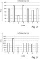
- Fig. 4 is graph schematically illustrating cell balancing times for a number of battery cells.
- the method comprises detecting that a second cell adjacent to the first cell has a higher than expected cell balancing time and that a third cell adjacent to the first cell has a higher than expected cell balancing time; and determining that the capacitor of the cell balancing circuitry of the first cell is faulty.
- the first cell is cell #3, which has a lower than average cell balancing time.
- the neighboring cells #2 and #4 have cell balancing times which are higher than expected.
- the Zener diode 202 of the cell measuring circuit 104 is faulty.
- the expected cell balancing time can be taken to be the average cell balancing time.
- the battery pack can also be assumed to comprise a larger number of battery cells such that the average cell balancing time for the plurality of cells is not largely influences by a few (i.e. 2-3) cells having deviating cell balancing times.
- Fig. 5 is graph schematically illustrating cell balancing times for a number of battery cells.
- the method comprises detecting that a second cell adjacent to the first cell has a higher than average cell balancing time and that a third cell adjacent to the first cell has an average cell balancing time; and determining that the capacitor of the cell balancing circuitry of the first cell is faulty.
- the first cell is cell #3, which has a lower than average cell balancing time.
- cell #2 has a cell balancing times which are higher than average and cell #4 has an average cell balancing time.
- a faulty capacitor allowing a current to run through the capacitor will lead to a current through the filter resistors which in turn will cause a voltage drop.
- the measured voltage over the cell will drop due to this failure and the voltage over the cell above will also increase with the same voltage. Thereby, it can be determined that the capacitor 202 of the cell measuring circuit 104 is faulty.
- a capacitor failure may for example be detected if a capacitor has a higher than normal self-discharging rate.
- the cell comprising a faulty cell measuring circuit 104 will have lower than expected cell balancing time. This occur since the faulty cell measuring circuit 104 will result in a lower measured voltage for that cell, and to compensate the rest of the cells in the pack are drained on charge (balanced) to reach the same lower voltage.
- the cells in the battery pack are connected in series such that each cell has two neighbors except for the cells at edges of the pack. This means that it may not be possible to determine the nature of a filature in a cell measuring circuit at the edge of the battery pack, i.e. if it is a faulty capacitor or a faulty Zener diode. However, the most important aspect is to determine if there is a failure at all, since a faulty cell measuring circuit may lead to overcharging and potentially excessive heating of a battery cell.
- the failures that is detected by this method is some of the possible failures that can occur to the described components where Zener level drift is a rare but likely failure mode and also a slow increase in the capacitor self-discharge is a rare but likely failure mode.
- An additional feature to consider when determining if the cell measuring circuit is faulty is the age of the battery.
- the spread in cell balancing time for the cells is expected to diverge, leading to an irregular pattern for the cell balancing times. This can for example be addressed by periodically resetting the accumulated cell balancing time used for determining if the cell measuring circuit is faulty.
- the balancing time threshold value can be determined based on an age of the battery, for example by being proportional to the age of the battery, at least for a comparison aimed at finding non-critical faults. Accordingly, an older battery may be allowed to exhibit a larger spread in cell balancing times before it is determined that the cell measuring circuit 104 is faulty.
- the cell balancing time threshold value is preferable the same irrespective of the age of the battery pack.
- a battery management system for a vehicle battery; the system comprising a battery management control unit connected to a plurality of cell measuring circuits, each cell measuring circuit being connected to a battery cell, wherein the battery management control unit is configured to: determine a cell voltage of each of the plurality of cells by the respective cell measuring circuit; perform cell balancing to balance a cell voltage for the plurality of cells; determine a cell balancing time for each cell; determine an expected cell balancing time for the plurality of cells; detect a first cell having a cell balancing time being lower than an average cell balancing time for the plurality of cells; detect that at least one cell adjacent to the first cell have a cell balancing time higher than the average cell balancing time for the plurality of cells; and if the difference in cell balancing time between the first cell and the at least one adjacent cell is higher than a predetermined balancing time threshold value, determine that the cell measuring circuit for the first cell is faulty.
- a computer program comprising instructions which, when executed on at least one processor, cause the at least one processor to carry out the method according to any one of the aforementioned embodiments, and a computer-readable storage medium, having stored thereon such a computer program.
Landscapes
- Engineering & Computer Science (AREA)
- Physics & Mathematics (AREA)
- General Physics & Mathematics (AREA)
- Power Engineering (AREA)
- Transportation (AREA)
- Mechanical Engineering (AREA)
- Sustainable Energy (AREA)
- Sustainable Development (AREA)
- Life Sciences & Earth Sciences (AREA)
- Chemical & Material Sciences (AREA)
- Chemical Kinetics & Catalysis (AREA)
- Manufacturing & Machinery (AREA)
- Electrochemistry (AREA)
- General Chemical & Material Sciences (AREA)
- Combustion & Propulsion (AREA)
- Microelectronics & Electronic Packaging (AREA)
- General Engineering & Computer Science (AREA)
- Secondary Cells (AREA)
- Charge And Discharge Circuits For Batteries Or The Like (AREA)
Abstract
Description
- The present disclosure relates to a system and method for detecting failures in a battery circuit for a vehicle battery. In particular, the disclosure relates to a method and system for detecting component failure in a cell measuring circuit in a battery comprising a plurality of battery cells.
- With the development of electrical and hybrid vehicles comes safety requirements related to the high-voltage electrical systems of such vehicles. Some of the requirements are defined by vehicle safety standards such as ISO 26262, "Road vehicles - Functional safety", where the highest safety level defined by the ISO-standard is ASIL-D (Automotive Safety Integrity Level). It may be both
- One application where a high level of safety is required relates to monitoring and balancing of the battery cells in an electric or hybrid vehicle. Battery cell monitoring and cell balancing is typically performed by dedicated cell monitoring/measuring circuitry. To fulfil the required safety levels, such circuitry needs to consist of components having very low failure rates, which may require expensive components, and/or the inclusion of other safety measures such as redundancy, potentially making the cell monitoring system more costly and complicated.
- Some known failure modes in control circuitry for a vehicle high-voltage battery may for example lead to cell overcharging which in turn may lead to a thermal event.
- Accordingly, there is a need for improved cell measuring and monitoring circuitry in fulfilling the required safety levels.
- In general, the disclosed subject matter relates to a method and system for detecting failures in a cell measuring circuit for a vehicle battery comprising a plurality of battery cells. First the method comprises determining a cell voltage of each of the plurality of cells by the respective cell measuring circuit. Next, the method comprises performing cell balancing to balance a cell voltage for the plurality of cells and the cell balancing times are compared to determine if there are deviating cell balancing times, and if there is an identifiable pattern in the cell balancing times which can provide an indication of a failure in any of the cell measuring circuits.
- The described method further comprises detecting a first cell having a cell balancing time being lower than an average cell balancing time for the plurality of cells; detecting that at least one cell adjacent to the first cell have a cell balancing time higher than the average cell balancing time for the plurality of cells; and if the difference in cell balancing time between the first cell and the at least one adjacent cell is higher than a predetermined balancing time threshold value, determining that the cell measuring circuit for the first cell is faulty.
- An advantage of the described method is that it can detect failures that would not be detectable by only monitoring the cell voltage. The balancing function will aim to balance the cells so that the cell voltage will be the same for all cells. If failure was to occur suddenly and is sufficiently large, the failure would be seen in the cell voltage. However, at a later point in time, the failure would not be seen be seen in the cell voltage but only in cell balancing time since the cell balancing function evens out the cell voltages. Furthermore, if the failure is a slow degradation of the component, then the failure cannot be distinguished from a normal deviation and the cell will slowly be balanced to keep the voltage difference low. Over time the error in the measurement due to a faulty cell measurement circuit will be big but it will not be detected when measuring the cell voltages, but it will be seen on the balancing time.
- Accordingly, the present invention provides a method for determining a fault in a cell measuring circuit which is based on detecting a pattern in the cell balancing times. The method can thus be employed without modifications to the cell measuring circuit as such, and the required safety levels can be reached without costly and complicated system designs.
-
-
FIG. 1 is a schematic illustration of a battery management system for a vehicle battery according to an embodiment of the invention; -
FIG. 2 is a circuit schematic illustrating a cell measuring circuit for a vehicle battery according to an embodiment of the invention; -
FIG. 3 is a flow chart outlining the general steps of a method for detecting failures in a cell measuring circuit according to an embodiment of the invention; -
FIG. 4 is a graph illustrating features of the method and system according to an embodiment of the invention; and -
FIG. 5 is a graph illustrating features of the method and system according to an embodiment of the invention. - The present invention will now be described more fully hereinafter with reference to the accompanying drawings, in which currently preferred embodiments of the invention are shown. This invention may, however, be embodied in many different forms and should not be construed as limited to the embodiments set forth herein; rather, these embodiments are provided for thoroughness and completeness, and fully convey the scope of the invention to the skilled person. Like reference characters refer to like elements throughout.
- In the following description, the claimed battery management system and method for detecting failures in a cell measuring circuit will be described with reference to a battery management system and a battery in a car. However, the described battery management system and method may equally well be used in other types of vehicles comprising chargeable batteries having a plurality of battery cells, such as boats or other marine vehicles, trucks, buses and aerial vehicles such as drones, airplanes and helicopters.
-
Fig. 1 schematically illustrates abattery management system 100 for avehicle battery 101. Thebattery management system 100 comprises a batterymanagement control unit 102 connected to a plurality ofcell measuring circuits 104, each cell measuring circuit being connected to abattery cell 106 such that eachbattery cell 106 has a dedicatedcell measuring circuit 104. - The battery
management control unit 102 may include a microprocessor, microcontroller, programmable digital signal processor or another programmable device. Thecontrol unit 102 may also, or instead, include an application specific integrated circuit, a programmable gate array or programmable array logic, a programmable logic device, or a digital signal processor. Where thecontrol unit 102 includes a programmable device such as the microprocessor, microcontroller or programmable digital signal processor mentioned above, the processor may further include computer executable code that controls operation of the programmable device. The functionality of thecontrol unit 102 may be provided by onededicated control unit 102, or it may be distributed over a plurality of control units. Moreover, the control unit may also be referred to as an ECU (Electronic Control Unit). -
Fig. 2 is a circuit schematic illustrating acell measuring circuit 104 for avehicle battery 101 according to an embodiment of the invention. Thecell measuring circuit 104 is arranged to measure the voltage of each battery cell. In thecell measuring circuit 104, acapacitor 202 is arranged as a filter to improve EMC properties and a Zenerdiode 204 is arranged to provide overvoltage protection. Accordingly, a fault in either thecapacitor 202 or the Zenerdiode 204 can be critical to function of the battery cell. -
FIG. 3 is a flow chart outlining the general steps of a method for detecting failures in acell measuring circuit 104 for avehicle battery 101 comprising a plurality ofbattery cells 106 according to an embodiment of the invention. The batterymanagement control unit 102 is configured to perform the steps of the method as will be described in the following. The method comprises determining 300 a cell voltage of each of the plurality ofcells 106 by the respectivecell measuring circuit 104. Accordingly, the cell voltages are determined to decide if cell balancing is needed and if so, how much cell balancing is needed and for which of the cells. Cell balancing is trigged by a difference in cell voltage at a specific cell voltage level (State-of-charge). The trigger for cell balancing can for example be controlled by an algorithm which is outside of the scope of the present disclosure. Moreover, various cell balancing schemes are well known in the field of battery management systems. - In the next step, cell balancing is performed 302 to balance a cell voltage for the plurality of cells, and a cell balancing time for each cell is determined 304. In order to improve the accuracy of the determined cell balancing time, the battery management control unit can be configured to increase the SoC threshold defining when cell balancing is triggered. In other words, if cell balancing is performed for small differences in SoC between cells, the determined cell balancing time may be more inaccurate.
- The method further comprises determining 306 an expected cell balancing time for the plurality of cells. The expected cell balancing time may for example be a predetermined value based on known parameters such as cell voltage and cell state-of-charge. The expected cell balancing time may also be based on previous empirical data describing cell balancing properties. In the following description, the expected cell balancing time will be described as the average cell balancing time for all cells. Accordingly, the cell balancing time for an individual battery cell is expected to be within a predetermined range of the average cell balancing time for all of the
cells 106 in thebattery pack 101. Thereby, the method also comprises storing the cell balancing time for each of the cells. When determining the average cell balancing time, it may be preferable to exclude the cells having the highest and lowest cell balancing time in order to reach an average value more representative of a normally functioning battery cell and cell measuring circuit. Thereby, faulty cells and faulty cell balancing circuits are not included in the determination of the average cell balancing time against which the cell balancing time for all cells are compared. - The cell balancing time is here defined as the total time that the cell is subject to cell balancing, and the cell balancing time may be determined as an accumulated cell balancing time for the respective cell. Thereby, the cell balancing time is not based on only one cell balancing event. To achieve an accurate comparison, the starting point from when the cell balancing times are accumulated is the same for all cells.
- The next step comprises detecting 308 a first cell having a cell balancing time lower than the expected cell balancing time for the plurality of cells and detecting 310 that at least one cell adjacent to the first cell have a cell balancing time higher than the expected cell balancing time for the plurality of cells. One individual cell may have deviating cell balancing time for a number of reasons, such as for an old or faulty cell, and it cannot be determined based on one deviating cell alone if there is a fault in the cell or if there is a fault in the
cell balancing circuitry 104. Accordingly, the cell balancing time for cells adjacent to the deviating cell is also acquired, and if a pattern is detected where one cell has a lower than expected cell balancing time and at least one adjacent cell has a higher than expected cell balancing time, it is further determined if the difference in cell balancing time between the first cell and the at least one adjacent cell is higher than a predetermined balancing time threshold value. - If the difference in cell balancing time between the first cell and the at least one adjacent cell is higher than a predetermined balancing time threshold value, it can be determined 312 that the
cell measuring circuit 104 for the first cell is faulty. Moreover, the cell balancing time may be compared to several different time threshold values. For example, a first time threshold value can be set to indicate a limit where there may be preferable to service or replace the battery cell or cell measuring circuit in order torn improve the life length of the battery cell, but where there is no safety issue. A second time threshold value higher than the first time threshold value can be set as a threshold value where a faulty cell measuring circuit poses a safety hazard and where repair or replacement is required. Moreover, the specific value for the time threshold values depends on the relation between cell balancing time and cell voltage value, and the time threshold values are thereby determined for the given implementation at hand and is based on properties of the battery cell and of the cell measuring circuit. - As illustrated in
Fig. 2 , thecell measuring circuit 104 comprises acapacitor 202 and aZener diode 204 connected in parallel with the battery cell, and the method further comprises determining that thecell measuring circuit 104 is faulty if it can be determined that either of theZener diode 204 or thecapacitor 202 is faulty. Moreover, as will be described in the following, it can be determined if it is thecapacitor 202 or theZener diode 204 that is faulty based on the pattern of the deviating cell balancing times. -
Fig. 4 is graph schematically illustrating cell balancing times for a number of battery cells. In order to determine if the cell measuring circuit comprises a faulty Zener diode, the method comprises detecting that a second cell adjacent to the first cell has a higher than expected cell balancing time and that a third cell adjacent to the first cell has a higher than expected cell balancing time; and determining that the capacitor of the cell balancing circuitry of the first cell is faulty. In the illustrated example, the first cell iscell # 3, which has a lower than average cell balancing time. Moreover, the neighboringcells # 2 and #4 have cell balancing times which are higher than expected. For the Zener diode failure illustrated inFig. 4 , and with further reference toFig. 2 , a current through the Zener diode, in the direction that is blocked by a functioning diode, will lead to a voltage drop over the circuit resistors which in turn causes the measured cell voltage to drop. Moreover, due to the voltage drop, each of the adjacent cells will experience an increased voltage by half of the amount of the voltage drop. Thereby, it can be determined that theZener diode 202 of thecell measuring circuit 104 is faulty. In the described examples, the expected cell balancing time can be taken to be the average cell balancing time. In a practical application, the battery pack can also be assumed to comprise a larger number of battery cells such that the average cell balancing time for the plurality of cells is not largely influences by a few (i.e. 2-3) cells having deviating cell balancing times. -
Fig. 5 is graph schematically illustrating cell balancing times for a number of battery cells. In order to determine if the cell measuring circuit comprises a faulty capacitor, the method comprises detecting that a second cell adjacent to the first cell has a higher than average cell balancing time and that a third cell adjacent to the first cell has an average cell balancing time; and determining that the capacitor of the cell balancing circuitry of the first cell is faulty. In the illustrated example, the first cell iscell # 3, which has a lower than average cell balancing time. Moreover, of the neighboringcells # 2 and #4,cell # 2 has a cell balancing times which are higher than average andcell # 4 has an average cell balancing time. For the capacitor failure illustrated inFig. 5 , and with further reference toFig. 2 , a faulty capacitor allowing a current to run through the capacitor will lead to a current through the filter resistors which in turn will cause a voltage drop. The measured voltage over the cell will drop due to this failure and the voltage over the cell above will also increase with the same voltage. Thereby, it can be determined that thecapacitor 202 of thecell measuring circuit 104 is faulty. A capacitor failure may for example be detected if a capacitor has a higher than normal self-discharging rate. - As can be seen in
Figs. 4 and 5 , the cell comprising a faultycell measuring circuit 104 will have lower than expected cell balancing time. This occur since the faultycell measuring circuit 104 will result in a lower measured voltage for that cell, and to compensate the rest of the cells in the pack are drained on charge (balanced) to reach the same lower voltage. - The cells in the battery pack are connected in series such that each cell has two neighbors except for the cells at edges of the pack. This means that it may not be possible to determine the nature of a filature in a cell measuring circuit at the edge of the battery pack, i.e. if it is a faulty capacitor or a faulty Zener diode. However, the most important aspect is to determine if there is a failure at all, since a faulty cell measuring circuit may lead to overcharging and potentially excessive heating of a battery cell.
- The failures that is detected by this method is some of the possible failures that can occur to the described components where Zener level drift is a rare but likely failure mode and also a slow increase in the capacitor self-discharge is a rare but likely failure mode.
- An additional feature to consider when determining if the cell measuring circuit is faulty is the age of the battery. As the battery ages, the spread in cell balancing time for the cells is expected to diverge, leading to an irregular pattern for the cell balancing times. This can for example be addressed by periodically resetting the accumulated cell balancing time used for determining if the cell measuring circuit is faulty. Moreover, the balancing time threshold value can be determined based on an age of the battery, for example by being proportional to the age of the battery, at least for a comparison aimed at finding non-critical faults. Accordingly, an older battery may be allowed to exhibit a larger spread in cell balancing times before it is determined that the
cell measuring circuit 104 is faulty. For the detection of safety critical faults, the cell balancing time threshold value is preferable the same irrespective of the age of the battery pack. - By means of the described method and system, critical faults in the cell measuring circuits of battery packs for vehicles can be detected without additional components or circuitry, which makes it bot easy to implement and cost effective since only software modifications may be required in existing systems.
- According to one embodiment of the invention, there is provided a battery management system for a vehicle battery; the system comprising a battery management control unit connected to a plurality of cell measuring circuits, each cell measuring circuit being connected to a battery cell, wherein the battery management control unit is configured to: determine a cell voltage of each of the plurality of cells by the respective cell measuring circuit; perform cell balancing to balance a cell voltage for the plurality of cells; determine a cell balancing time for each cell; determine an expected cell balancing time for the plurality of cells; detect a first cell having a cell balancing time being lower than an average cell balancing time for the plurality of cells; detect that at least one cell adjacent to the first cell have a cell balancing time higher than the average cell balancing time for the plurality of cells; and if the difference in cell balancing time between the first cell and the at least one adjacent cell is higher than a predetermined balancing time threshold value, determine that the cell measuring circuit for the first cell is faulty.
- According to one embodiment of the invention, there is provided a computer program, comprising instructions which, when executed on at least one processor, cause the at least one processor to carry out the method according to any one of the aforementioned embodiments, and a computer-readable storage medium, having stored thereon such a computer program.
- Even though the invention has been described with reference to specific exemplifying embodiments thereof, many different alterations, modifications and the like will become apparent for those skilled in the art. For example, the method may be used also for other types of cell measuring circuits. Also, it should be noted that parts of the method and system may be omitted, interchanged or arranged in various ways, the method and system yet being able to perform the functionality of the present invention.
- Additionally, variations to the disclosed embodiments can be understood and effected by the skilled person in practicing the claimed invention, from a study of the drawings, the disclosure, and the appended claims. In the claims, the word "comprising" does not exclude other elements or steps, and the indefinite article "a" or "an" does not exclude a plurality. The mere fact that certain measures are recited in mutually different dependent claims does not indicate that a combination of these measured cannot be used to advantage.
Claims (15)
- A method for detecting failures in a cell measuring circuit (104) for a vehicle battery (101) comprising a plurality of battery cells (106), each cell having a cell measuring circuit (104) connected to the cell, the method comprising:determining (300) a cell voltage of each of the plurality of cells by the respective cell measuring circuit;performing (302) cell balancing to balance a cell voltage for the plurality of cells;determining (304) a cell balancing time for each cell;determining (306) an expected cell balancing time for the plurality of cells;detecting (308) a first cell having a cell balancing time lower than the expected cell balancing time for the plurality of cells;detecting (310) that at least one cell adjacent to the first cell have a cell balancing time higher than the expected cell balancing time for the plurality of cells; andif the difference in cell balancing time between the first cell and the at least one adjacent cell is higher than a predetermined balancing time threshold value, determining (312) that the cell measuring circuit for the first cell is faulty.
- The method according to claim 1, wherein determining an expected cell balancing time for each cell comprises determining an average cell balancing time for the plurality of cells.
- The method according to claim 2, wherein the cell balancing time for each cell is determined as an accumulated cell balancing time.
- The method according to any one of the preceding claims, wherein the cell measuring circuit comprises a capacitor and a Zener diode connected in parallel with the battery cell, and wherein determining that the cell measuring circuit is faulty comprises determining if the capacitor or the Zener diode is faulty.
- The method according to claim 4, further comprising:detecting that a second cell adjacent to the first cell has a higher than expected cell balancing time and that a third cell adjacent to the first cell has a higher than expected cell balancing time; anddetermining that the Zener diode of the cell balancing circuitry of the first cell is faulty.
- The method according to claim 4, further comprising:detecting that a second cell adjacent to the first cell has a higher than expected cell balancing time and that a third cell adjacent to the first cell has an expected balancing time; anddetermining that the capacitor of the cell balancing circuitry of the first cell is faulty.
- The method according to any one of the preceding claims, wherein the balancing time threshold value is determined based on an age of the battery.
- The method according to claim 7, wherein the balancing time threshold value is proportional to the age of the battery.
- A battery management system for a vehicle battery; the system comprising a battery management control unit connected to a plurality of cell measuring circuits, each cell measuring circuit being connected to a battery cell, wherein the battery management control unit is configured to:determine a cell voltage of each of the plurality of cells by the respective cell measuring circuit;perform cell balancing to balance a cell voltage for the plurality of cells;determine a cell balancing time for each cell;determine an expected cell balancing time for the plurality of cells;detect a first cell having a cell balancing time being lower than an average cell balancing time for the plurality of cells;detect that at least one cell adjacent to the first cell have a cell balancing time higher than the average cell balancing time for the plurality of cells; andif the difference in cell balancing time between the first cell and the at least one adjacent cell is higher than a predetermined balancing time threshold value, determine that the cell measuring circuit for the first cell is faulty.
- The system according to claim 9, wherein the expected cell balancing time is an average cell balancing time for the plurality of cells.
- The battery management system according to claim 9 or 10, wherein the cell balancing circuit comprises a capacitor and a Zener diode connected in parallel with the cell, and the battery management control unit is configured to determine that the cell measuring circuit is faulty is it is determined that the Zener diode or the capacitor is faulty.
- The battery management system according to any one of claims 9 to 11, wherein the battery management control unit is configured to determine the cell balancing time for each cell as an accumulated cell balancing time.
- The battery management system according to any one of claims 9 to 12, wherein the battery management control unit is further configured to detect that a second cell adjacent to the first cell has a higher than average cell balancing time and that a third cell adjacent to the first cell has an average cell balancing time; and to determine that the capacitor of the cell balancing circuitry of the first cell is faulty.
- The battery management system according to any one of claims 9 to 13, wherein the battery management control unit is further configured to detect that a second cell adjacent to the first cell has a higher than average cell balancing time and that a third cell adjacent to the first cell has a higher than average cell balancing time; and to determine that the Zener diode of the cell balancing circuitry of the first cell is faulty.
- A vehicle comprising a battery management system according to any one of claims 9 to 14.
Priority Applications (3)
| Application Number | Priority Date | Filing Date | Title |
|---|---|---|---|
| EP19209709.5A EP3822645B1 (en) | 2019-11-18 | 2019-11-18 | System and method for detecting failures in a battery management system for a vehicle battery |
| CN202011277583.4A CN112824128B (en) | 2019-11-18 | 2020-11-16 | System and method for detecting faults in a battery management system for a vehicle battery |
| US17/099,845 US11422193B2 (en) | 2019-11-18 | 2020-11-17 | System and method for detecting failures in a battery management system for a vehicle battery |
Applications Claiming Priority (1)
| Application Number | Priority Date | Filing Date | Title |
|---|---|---|---|
| EP19209709.5A EP3822645B1 (en) | 2019-11-18 | 2019-11-18 | System and method for detecting failures in a battery management system for a vehicle battery |
Publications (2)
| Publication Number | Publication Date |
|---|---|
| EP3822645A1 true EP3822645A1 (en) | 2021-05-19 |
| EP3822645B1 EP3822645B1 (en) | 2022-10-26 |
Family
ID=68609974
Family Applications (1)
| Application Number | Title | Priority Date | Filing Date |
|---|---|---|---|
| EP19209709.5A Active EP3822645B1 (en) | 2019-11-18 | 2019-11-18 | System and method for detecting failures in a battery management system for a vehicle battery |
Country Status (3)
| Country | Link |
|---|---|
| US (1) | US11422193B2 (en) |
| EP (1) | EP3822645B1 (en) |
| CN (1) | CN112824128B (en) |
Families Citing this family (2)
| Publication number | Priority date | Publication date | Assignee | Title |
|---|---|---|---|---|
| US11768232B2 (en) * | 2018-01-25 | 2023-09-26 | Volvo Construction Equipment Ab | Equalizer overload management |
| JP2024520459A (en) * | 2021-05-25 | 2024-05-24 | ヒタチ・エナジー・リミテッド | SYSTEM WITH ENERGY STORAGE UNIT AND METHOD IN SUCH SYSTEM - Patent application |
Citations (7)
| Publication number | Priority date | Publication date | Assignee | Title |
|---|---|---|---|---|
| JP2007085847A (en) * | 2005-09-21 | 2007-04-05 | Hitachi Vehicle Energy Ltd | Abnormality detection system for cell balance circuit |
| EP2085784A2 (en) * | 2008-01-29 | 2009-08-05 | Hitachi Ltd. | Battery system for vehicle, on-vehicle battery module, and cell controller |
| JP2009210480A (en) * | 2008-03-05 | 2009-09-17 | Nissan Motor Co Ltd | Failure diagnosis method of cell voltage sensing device |
| KR20100020113A (en) * | 2008-08-12 | 2010-02-22 | 현대자동차주식회사 | Method of balancing cell in battery pack of hev |
| US20110285538A1 (en) * | 2010-03-05 | 2011-11-24 | Sang-Hoon Lee | Apparatus and method for diagnosing abnormality in cell balancing circuit |
| US20110285539A1 (en) * | 2010-02-22 | 2011-11-24 | Sang-Hoon Lee | Apparatus and method for diagnosing abnormality in cell balancing circuit |
| US10063068B1 (en) * | 2017-04-11 | 2018-08-28 | Lg Chem, Ltd. | Battery system |
Family Cites Families (12)
| Publication number | Priority date | Publication date | Assignee | Title |
|---|---|---|---|---|
| KR101444962B1 (en) | 2006-07-19 | 2014-09-26 | 에이일이삼 시스템즈 인코포레이티드 | Method and system for monitoring and balancing cells in battery packs |
| US9097774B2 (en) | 2011-07-14 | 2015-08-04 | Southwest Electronic Energy Corporation | Short detection in battery cells |
| US8796993B2 (en) | 2011-09-12 | 2014-08-05 | Southwest Electronic Energy Corporation | Historical analysis of battery cells for determining state of health |
| US20130257382A1 (en) * | 2012-04-02 | 2013-10-03 | Apple Inc. | Managing Cycle and Runtime in Batteries for Portable Electronic Devices |
| JP5928509B2 (en) * | 2014-03-12 | 2016-06-01 | トヨタ自動車株式会社 | Battery monitoring device |
| DE102014214996A1 (en) * | 2014-07-30 | 2016-02-04 | Robert Bosch Gmbh | Method for operating a battery system |
| CN107517594B (en) * | 2015-04-03 | 2019-11-05 | 松下知识产权经营株式会社 | Fault detection means |
| JP6419046B2 (en) * | 2015-09-15 | 2018-11-07 | 本田技研工業株式会社 | Failure type determination device for power storage system |
| US9840161B2 (en) * | 2016-03-10 | 2017-12-12 | Ford Global Technologies, Llc | Circuit and method for detection of battery cell degradation events |
| US9876369B2 (en) | 2016-03-15 | 2018-01-23 | Lg Chem, Ltd. | Battery system and method for determining an open circuit fault condition in a battery module |
| KR102025286B1 (en) * | 2016-07-12 | 2019-09-26 | 주식회사 엘지화학 | Battery cell-balancing method and system |
| US11187758B2 (en) * | 2016-10-19 | 2021-11-30 | San Diego State University Research Foundation | Methods and circuitry for fault detection and automatic equalizers for battery packs |
-
2019
- 2019-11-18 EP EP19209709.5A patent/EP3822645B1/en active Active
-
2020
- 2020-11-16 CN CN202011277583.4A patent/CN112824128B/en active Active
- 2020-11-17 US US17/099,845 patent/US11422193B2/en active Active
Patent Citations (7)
| Publication number | Priority date | Publication date | Assignee | Title |
|---|---|---|---|---|
| JP2007085847A (en) * | 2005-09-21 | 2007-04-05 | Hitachi Vehicle Energy Ltd | Abnormality detection system for cell balance circuit |
| EP2085784A2 (en) * | 2008-01-29 | 2009-08-05 | Hitachi Ltd. | Battery system for vehicle, on-vehicle battery module, and cell controller |
| JP2009210480A (en) * | 2008-03-05 | 2009-09-17 | Nissan Motor Co Ltd | Failure diagnosis method of cell voltage sensing device |
| KR20100020113A (en) * | 2008-08-12 | 2010-02-22 | 현대자동차주식회사 | Method of balancing cell in battery pack of hev |
| US20110285539A1 (en) * | 2010-02-22 | 2011-11-24 | Sang-Hoon Lee | Apparatus and method for diagnosing abnormality in cell balancing circuit |
| US20110285538A1 (en) * | 2010-03-05 | 2011-11-24 | Sang-Hoon Lee | Apparatus and method for diagnosing abnormality in cell balancing circuit |
| US10063068B1 (en) * | 2017-04-11 | 2018-08-28 | Lg Chem, Ltd. | Battery system |
Non-Patent Citations (1)
| Title |
|---|
| JIAN CAO ET AL: "Battery balancing methods: A comprehensive review", VEHICLE POWER AND PROPULSION CONFERENCE, 2008. VPPC '08. IEEE, IEEE, PISCATAWAY, NJ, USA, 3 September 2008 (2008-09-03), pages 1 - 6, XP031363349, ISBN: 978-1-4244-1848-0 * |
Also Published As
| Publication number | Publication date |
|---|---|
| CN112824128A (en) | 2021-05-21 |
| CN112824128B (en) | 2023-04-07 |
| US11422193B2 (en) | 2022-08-23 |
| EP3822645B1 (en) | 2022-10-26 |
| US20210148980A1 (en) | 2021-05-20 |
Similar Documents
| Publication | Publication Date | Title |
|---|---|---|
| US9459324B2 (en) | Device and method for the redundant determination of a battery current flowing through the poles of a battery | |
| US11125829B2 (en) | Management device, and power storage system | |
| US8164433B2 (en) | Detecting faults in a wiring harness | |
| JP6697869B2 (en) | State determination device and state determination method | |
| US11422193B2 (en) | System and method for detecting failures in a battery management system for a vehicle battery | |
| EP3032633B1 (en) | Battery control system, and vehicle control system | |
| US9411004B2 (en) | Continuous leakage detection circuit with integrated robustness check and balanced fault detection | |
| US20170366005A1 (en) | Management device and power storage system | |
| JP5286708B2 (en) | Secondary battery abnormality detection device and abnormality detection method | |
| CN113795964A (en) | Battery diagnosis apparatus and method | |
| US10836338B2 (en) | Method and device for monitoring an energy reserve and safety device for a vehicle | |
| US10809291B2 (en) | Method for detecting a proper connection of at least one energy store to an on-board electrical system | |
| KR20160144484A (en) | Method and device for ascertaining an inner resistance of a supply network for supplying energy to a personal protection device of a vehicle | |
| KR102151048B1 (en) | Apparatus and method for determining reference voltage of detecting overcharge of battery | |
| JP2018501613A (en) | Method and apparatus for detecting overcharge of a battery accumulator | |
| JP2019163948A (en) | Monitor device of battery | |
| KR102642100B1 (en) | Method for diagnosing failure of relays | |
| CN116572745A (en) | Power battery fault processing method, device and storage medium | |
| KR101361285B1 (en) | Fault detecting method of vehicle | |
| CN107110917B (en) | Method for monitoring a battery pack and monitoring device | |
| JPWO2015022731A1 (en) | Battery monitoring device, battery system and vehicle control system | |
| CN110869781B (en) | System and method for diagnosing an anomaly in a master control unit | |
| JP6865649B2 (en) | Controls, battery monitoring systems, and battery monitoring methods | |
| CN112068012A (en) | Detecting a latent fault in a cell of an energy storage system | |
| JP6632372B2 (en) | State determination device and state determination method |
Legal Events
| Date | Code | Title | Description |
|---|---|---|---|
| PUAI | Public reference made under article 153(3) epc to a published international application that has entered the european phase |
Free format text: ORIGINAL CODE: 0009012 |
|
| STAA | Information on the status of an ep patent application or granted ep patent |
Free format text: STATUS: THE APPLICATION HAS BEEN PUBLISHED |
|
| AK | Designated contracting states |
Kind code of ref document: A1 Designated state(s): AL AT BE BG CH CY CZ DE DK EE ES FI FR GB GR HR HU IE IS IT LI LT LU LV MC MK MT NL NO PL PT RO RS SE SI SK SM TR |
|
| STAA | Information on the status of an ep patent application or granted ep patent |
Free format text: STATUS: REQUEST FOR EXAMINATION WAS MADE |
|
| 17P | Request for examination filed |
Effective date: 20211119 |
|
| RBV | Designated contracting states (corrected) |
Designated state(s): AL AT BE BG CH CY CZ DE DK EE ES FI FR GB GR HR HU IE IS IT LI LT LU LV MC MK MT NL NO PL PT RO RS SE SI SK SM TR |
|
| RIC1 | Information provided on ipc code assigned before grant |
Ipc: H01M 10/48 20060101ALI20220428BHEP Ipc: H02J 7/00 20060101ALI20220428BHEP Ipc: H01M 10/42 20060101ALI20220428BHEP Ipc: G01R 31/396 20190101ALI20220428BHEP Ipc: B60L 58/22 20190101ALI20220428BHEP Ipc: G01R 19/165 20060101AFI20220428BHEP |
|
| GRAP | Despatch of communication of intention to grant a patent |
Free format text: ORIGINAL CODE: EPIDOSNIGR1 |
|
| STAA | Information on the status of an ep patent application or granted ep patent |
Free format text: STATUS: GRANT OF PATENT IS INTENDED |
|
| INTG | Intention to grant announced |
Effective date: 20220603 |
|
| GRAS | Grant fee paid |
Free format text: ORIGINAL CODE: EPIDOSNIGR3 |
|
| GRAA | (expected) grant |
Free format text: ORIGINAL CODE: 0009210 |
|
| STAA | Information on the status of an ep patent application or granted ep patent |
Free format text: STATUS: THE PATENT HAS BEEN GRANTED |
|
| AK | Designated contracting states |
Kind code of ref document: B1 Designated state(s): AL AT BE BG CH CY CZ DE DK EE ES FI FR GB GR HR HU IE IS IT LI LT LU LV MC MK MT NL NO PL PT RO RS SE SI SK SM TR |
|
| REG | Reference to a national code |
Ref country code: GB Ref legal event code: FG4D |
|
| REG | Reference to a national code |
Ref country code: CH Ref legal event code: EP |
|
| REG | Reference to a national code |
Ref country code: DE Ref legal event code: R096 Ref document number: 602019021039 Country of ref document: DE |
|
| REG | Reference to a national code |
Ref country code: AT Ref legal event code: REF Ref document number: 1527393 Country of ref document: AT Kind code of ref document: T Effective date: 20221115 |
|
| REG | Reference to a national code |
Ref country code: IE Ref legal event code: FG4D |
|
| REG | Reference to a national code |
Ref country code: LT Ref legal event code: MG9D |
|
| REG | Reference to a national code |
Ref country code: NL Ref legal event code: MP Effective date: 20221026 |
|
| REG | Reference to a national code |
Ref country code: AT Ref legal event code: MK05 Ref document number: 1527393 Country of ref document: AT Kind code of ref document: T Effective date: 20221026 |
|
| PG25 | Lapsed in a contracting state [announced via postgrant information from national office to epo] |
Ref country code: NL Free format text: LAPSE BECAUSE OF FAILURE TO SUBMIT A TRANSLATION OF THE DESCRIPTION OR TO PAY THE FEE WITHIN THE PRESCRIBED TIME-LIMIT Effective date: 20221026 |
|
| PG25 | Lapsed in a contracting state [announced via postgrant information from national office to epo] |
Ref country code: SE Free format text: LAPSE BECAUSE OF FAILURE TO SUBMIT A TRANSLATION OF THE DESCRIPTION OR TO PAY THE FEE WITHIN THE PRESCRIBED TIME-LIMIT Effective date: 20221026 Ref country code: PT Free format text: LAPSE BECAUSE OF FAILURE TO SUBMIT A TRANSLATION OF THE DESCRIPTION OR TO PAY THE FEE WITHIN THE PRESCRIBED TIME-LIMIT Effective date: 20230227 Ref country code: NO Free format text: LAPSE BECAUSE OF FAILURE TO SUBMIT A TRANSLATION OF THE DESCRIPTION OR TO PAY THE FEE WITHIN THE PRESCRIBED TIME-LIMIT Effective date: 20230126 Ref country code: LT Free format text: LAPSE BECAUSE OF FAILURE TO SUBMIT A TRANSLATION OF THE DESCRIPTION OR TO PAY THE FEE WITHIN THE PRESCRIBED TIME-LIMIT Effective date: 20221026 Ref country code: FI Free format text: LAPSE BECAUSE OF FAILURE TO SUBMIT A TRANSLATION OF THE DESCRIPTION OR TO PAY THE FEE WITHIN THE PRESCRIBED TIME-LIMIT Effective date: 20221026 Ref country code: ES Free format text: LAPSE BECAUSE OF FAILURE TO SUBMIT A TRANSLATION OF THE DESCRIPTION OR TO PAY THE FEE WITHIN THE PRESCRIBED TIME-LIMIT Effective date: 20221026 Ref country code: AT Free format text: LAPSE BECAUSE OF FAILURE TO SUBMIT A TRANSLATION OF THE DESCRIPTION OR TO PAY THE FEE WITHIN THE PRESCRIBED TIME-LIMIT Effective date: 20221026 |
|
| PG25 | Lapsed in a contracting state [announced via postgrant information from national office to epo] |
Ref country code: RS Free format text: LAPSE BECAUSE OF FAILURE TO SUBMIT A TRANSLATION OF THE DESCRIPTION OR TO PAY THE FEE WITHIN THE PRESCRIBED TIME-LIMIT Effective date: 20221026 Ref country code: PL Free format text: LAPSE BECAUSE OF FAILURE TO SUBMIT A TRANSLATION OF THE DESCRIPTION OR TO PAY THE FEE WITHIN THE PRESCRIBED TIME-LIMIT Effective date: 20221026 Ref country code: LV Free format text: LAPSE BECAUSE OF FAILURE TO SUBMIT A TRANSLATION OF THE DESCRIPTION OR TO PAY THE FEE WITHIN THE PRESCRIBED TIME-LIMIT Effective date: 20221026 Ref country code: IS Free format text: LAPSE BECAUSE OF FAILURE TO SUBMIT A TRANSLATION OF THE DESCRIPTION OR TO PAY THE FEE WITHIN THE PRESCRIBED TIME-LIMIT Effective date: 20230226 Ref country code: HR Free format text: LAPSE BECAUSE OF FAILURE TO SUBMIT A TRANSLATION OF THE DESCRIPTION OR TO PAY THE FEE WITHIN THE PRESCRIBED TIME-LIMIT Effective date: 20221026 Ref country code: GR Free format text: LAPSE BECAUSE OF FAILURE TO SUBMIT A TRANSLATION OF THE DESCRIPTION OR TO PAY THE FEE WITHIN THE PRESCRIBED TIME-LIMIT Effective date: 20230127 |
|
| REG | Reference to a national code |
Ref country code: CH Ref legal event code: PL |
|
| REG | Reference to a national code |
Ref country code: DE Ref legal event code: R097 Ref document number: 602019021039 Country of ref document: DE Ref country code: BE Ref legal event code: MM Effective date: 20221130 |
|
| PG25 | Lapsed in a contracting state [announced via postgrant information from national office to epo] |
Ref country code: SM Free format text: LAPSE BECAUSE OF FAILURE TO SUBMIT A TRANSLATION OF THE DESCRIPTION OR TO PAY THE FEE WITHIN THE PRESCRIBED TIME-LIMIT Effective date: 20221026 Ref country code: RO Free format text: LAPSE BECAUSE OF FAILURE TO SUBMIT A TRANSLATION OF THE DESCRIPTION OR TO PAY THE FEE WITHIN THE PRESCRIBED TIME-LIMIT Effective date: 20221026 Ref country code: MC Free format text: LAPSE BECAUSE OF FAILURE TO SUBMIT A TRANSLATION OF THE DESCRIPTION OR TO PAY THE FEE WITHIN THE PRESCRIBED TIME-LIMIT Effective date: 20221026 Ref country code: LI Free format text: LAPSE BECAUSE OF NON-PAYMENT OF DUE FEES Effective date: 20221130 Ref country code: EE Free format text: LAPSE BECAUSE OF FAILURE TO SUBMIT A TRANSLATION OF THE DESCRIPTION OR TO PAY THE FEE WITHIN THE PRESCRIBED TIME-LIMIT Effective date: 20221026 Ref country code: DK Free format text: LAPSE BECAUSE OF FAILURE TO SUBMIT A TRANSLATION OF THE DESCRIPTION OR TO PAY THE FEE WITHIN THE PRESCRIBED TIME-LIMIT Effective date: 20221026 Ref country code: CZ Free format text: LAPSE BECAUSE OF FAILURE TO SUBMIT A TRANSLATION OF THE DESCRIPTION OR TO PAY THE FEE WITHIN THE PRESCRIBED TIME-LIMIT Effective date: 20221026 Ref country code: CH Free format text: LAPSE BECAUSE OF NON-PAYMENT OF DUE FEES Effective date: 20221130 |
|
| PG25 | Lapsed in a contracting state [announced via postgrant information from national office to epo] |
Ref country code: SK Free format text: LAPSE BECAUSE OF FAILURE TO SUBMIT A TRANSLATION OF THE DESCRIPTION OR TO PAY THE FEE WITHIN THE PRESCRIBED TIME-LIMIT Effective date: 20221026 Ref country code: LU Free format text: LAPSE BECAUSE OF NON-PAYMENT OF DUE FEES Effective date: 20221118 Ref country code: AL Free format text: LAPSE BECAUSE OF FAILURE TO SUBMIT A TRANSLATION OF THE DESCRIPTION OR TO PAY THE FEE WITHIN THE PRESCRIBED TIME-LIMIT Effective date: 20221026 |
|
| PLBE | No opposition filed within time limit |
Free format text: ORIGINAL CODE: 0009261 |
|
| STAA | Information on the status of an ep patent application or granted ep patent |
Free format text: STATUS: NO OPPOSITION FILED WITHIN TIME LIMIT |
|
| 26N | No opposition filed |
Effective date: 20230727 |
|
| PG25 | Lapsed in a contracting state [announced via postgrant information from national office to epo] |
Ref country code: IE Free format text: LAPSE BECAUSE OF NON-PAYMENT OF DUE FEES Effective date: 20221118 |
|
| PG25 | Lapsed in a contracting state [announced via postgrant information from national office to epo] |
Ref country code: SI Free format text: LAPSE BECAUSE OF FAILURE TO SUBMIT A TRANSLATION OF THE DESCRIPTION OR TO PAY THE FEE WITHIN THE PRESCRIBED TIME-LIMIT Effective date: 20221026 Ref country code: BE Free format text: LAPSE BECAUSE OF NON-PAYMENT OF DUE FEES Effective date: 20221130 |
|
| P01 | Opt-out of the competence of the unified patent court (upc) registered |
Effective date: 20231212 |
|
| PGFP | Annual fee paid to national office [announced via postgrant information from national office to epo] |
Ref country code: GB Payment date: 20231019 Year of fee payment: 5 |
|
| PGFP | Annual fee paid to national office [announced via postgrant information from national office to epo] |
Ref country code: FR Payment date: 20231020 Year of fee payment: 5 Ref country code: DE Payment date: 20231019 Year of fee payment: 5 |
|
| PG25 | Lapsed in a contracting state [announced via postgrant information from national office to epo] |
Ref country code: CY Free format text: LAPSE BECAUSE OF FAILURE TO SUBMIT A TRANSLATION OF THE DESCRIPTION OR TO PAY THE FEE WITHIN THE PRESCRIBED TIME-LIMIT Effective date: 20221026 |