EP3816745B1 - Device for automatically operating machining center using cad data - Google Patents
Device for automatically operating machining center using cad data Download PDFInfo
- Publication number
- EP3816745B1 EP3816745B1 EP19918498.7A EP19918498A EP3816745B1 EP 3816745 B1 EP3816745 B1 EP 3816745B1 EP 19918498 A EP19918498 A EP 19918498A EP 3816745 B1 EP3816745 B1 EP 3816745B1
- Authority
- EP
- European Patent Office
- Prior art keywords
- machining
- tool
- automatic
- manufacturing process
- unit
- Prior art date
- Legal status (The legal status is an assumption and is not a legal conclusion. Google has not performed a legal analysis and makes no representation as to the accuracy of the status listed.)
- Active
Links
- 238000003754 machining Methods 0.000 claims description 158
- 238000004519 manufacturing process Methods 0.000 claims description 96
- 238000005520 cutting process Methods 0.000 claims description 45
- 230000006870 function Effects 0.000 claims description 43
- 238000013461 design Methods 0.000 claims description 33
- 239000000463 material Substances 0.000 claims description 24
- 238000000034 method Methods 0.000 claims description 24
- 238000004088 simulation Methods 0.000 claims description 16
- 238000003860 storage Methods 0.000 claims description 9
- 238000000605 extraction Methods 0.000 claims description 5
- 230000006872 improvement Effects 0.000 claims description 5
- 238000001514 detection method Methods 0.000 claims description 4
- 230000002093 peripheral effect Effects 0.000 claims description 4
- 238000011960 computer-aided design Methods 0.000 description 42
- 230000008569 process Effects 0.000 description 11
- 238000010586 diagram Methods 0.000 description 8
- 239000004973 liquid crystal related substance Substances 0.000 description 7
- 238000004590 computer program Methods 0.000 description 4
- 238000004891 communication Methods 0.000 description 3
- 238000005516 engineering process Methods 0.000 description 3
- 238000012549 training Methods 0.000 description 3
- 230000004075 alteration Effects 0.000 description 2
- 230000008859 change Effects 0.000 description 2
- 230000000694 effects Effects 0.000 description 2
- 238000010801 machine learning Methods 0.000 description 2
- 238000005457 optimization Methods 0.000 description 2
- 238000012545 processing Methods 0.000 description 2
- 230000009467 reduction Effects 0.000 description 2
- 230000001960 triggered effect Effects 0.000 description 2
- 238000012795 verification Methods 0.000 description 2
- 238000012937 correction Methods 0.000 description 1
- 238000006073 displacement reaction Methods 0.000 description 1
- 238000005553 drilling Methods 0.000 description 1
- 239000000284 extract Substances 0.000 description 1
- 238000000227 grinding Methods 0.000 description 1
- 230000010365 information processing Effects 0.000 description 1
- 230000013011 mating Effects 0.000 description 1
- 238000003801 milling Methods 0.000 description 1
- 238000012986 modification Methods 0.000 description 1
- 230000004048 modification Effects 0.000 description 1
- 230000004044 response Effects 0.000 description 1
Images


Classifications
-
- G—PHYSICS
- G05—CONTROLLING; REGULATING
- G05B—CONTROL OR REGULATING SYSTEMS IN GENERAL; FUNCTIONAL ELEMENTS OF SUCH SYSTEMS; MONITORING OR TESTING ARRANGEMENTS FOR SUCH SYSTEMS OR ELEMENTS
- G05B19/00—Programme-control systems
- G05B19/02—Programme-control systems electric
- G05B19/18—Numerical control [NC], i.e. automatically operating machines, in particular machine tools, e.g. in a manufacturing environment, so as to execute positioning, movement or co-ordinated operations by means of programme data in numerical form
- G05B19/4097—Numerical control [NC], i.e. automatically operating machines, in particular machine tools, e.g. in a manufacturing environment, so as to execute positioning, movement or co-ordinated operations by means of programme data in numerical form characterised by using design data to control NC machines, e.g. CAD/CAM
-
- G—PHYSICS
- G05—CONTROLLING; REGULATING
- G05B—CONTROL OR REGULATING SYSTEMS IN GENERAL; FUNCTIONAL ELEMENTS OF SUCH SYSTEMS; MONITORING OR TESTING ARRANGEMENTS FOR SUCH SYSTEMS OR ELEMENTS
- G05B19/00—Programme-control systems
- G05B19/02—Programme-control systems electric
- G05B19/18—Numerical control [NC], i.e. automatically operating machines, in particular machine tools, e.g. in a manufacturing environment, so as to execute positioning, movement or co-ordinated operations by means of programme data in numerical form
- G05B19/406—Numerical control [NC], i.e. automatically operating machines, in particular machine tools, e.g. in a manufacturing environment, so as to execute positioning, movement or co-ordinated operations by means of programme data in numerical form characterised by monitoring or safety
- G05B19/4068—Verifying part programme on screen, by drawing or other means
-
- G—PHYSICS
- G05—CONTROLLING; REGULATING
- G05B—CONTROL OR REGULATING SYSTEMS IN GENERAL; FUNCTIONAL ELEMENTS OF SUCH SYSTEMS; MONITORING OR TESTING ARRANGEMENTS FOR SUCH SYSTEMS OR ELEMENTS
- G05B2219/00—Program-control systems
- G05B2219/30—Nc systems
- G05B2219/35—Nc in input of data, input till input file format
- G05B2219/35159—With nominal blank and model in memory define tool path and machine workpiece
-
- G—PHYSICS
- G05—CONTROLLING; REGULATING
- G05B—CONTROL OR REGULATING SYSTEMS IN GENERAL; FUNCTIONAL ELEMENTS OF SUCH SYSTEMS; MONITORING OR TESTING ARRANGEMENTS FOR SUCH SYSTEMS OR ELEMENTS
- G05B2219/00—Program-control systems
- G05B2219/30—Nc systems
- G05B2219/35—Nc in input of data, input till input file format
- G05B2219/35165—Automatic cutter selection
-
- G—PHYSICS
- G05—CONTROLLING; REGULATING
- G05B—CONTROL OR REGULATING SYSTEMS IN GENERAL; FUNCTIONAL ELEMENTS OF SUCH SYSTEMS; MONITORING OR TESTING ARRANGEMENTS FOR SUCH SYSTEMS OR ELEMENTS
- G05B2219/00—Program-control systems
- G05B2219/30—Nc systems
- G05B2219/35—Nc in input of data, input till input file format
- G05B2219/35167—Automatic toolpath generation and tool selection
-
- G—PHYSICS
- G05—CONTROLLING; REGULATING
- G05B—CONTROL OR REGULATING SYSTEMS IN GENERAL; FUNCTIONAL ELEMENTS OF SUCH SYSTEMS; MONITORING OR TESTING ARRANGEMENTS FOR SUCH SYSTEMS OR ELEMENTS
- G05B2219/00—Program-control systems
- G05B2219/30—Nc systems
- G05B2219/35—Nc in input of data, input till input file format
- G05B2219/35287—Verify, check program by drawing, display part, testpiece
-
- G—PHYSICS
- G05—CONTROLLING; REGULATING
- G05B—CONTROL OR REGULATING SYSTEMS IN GENERAL; FUNCTIONAL ELEMENTS OF SUCH SYSTEMS; MONITORING OR TESTING ARRANGEMENTS FOR SUCH SYSTEMS OR ELEMENTS
- G05B2219/00—Program-control systems
- G05B2219/30—Nc systems
- G05B2219/35—Nc in input of data, input till input file format
- G05B2219/35313—Display, validate tool path for boundary, surface interference
-
- Y—GENERAL TAGGING OF NEW TECHNOLOGICAL DEVELOPMENTS; GENERAL TAGGING OF CROSS-SECTIONAL TECHNOLOGIES SPANNING OVER SEVERAL SECTIONS OF THE IPC; TECHNICAL SUBJECTS COVERED BY FORMER USPC CROSS-REFERENCE ART COLLECTIONS [XRACs] AND DIGESTS
- Y02—TECHNOLOGIES OR APPLICATIONS FOR MITIGATION OR ADAPTATION AGAINST CLIMATE CHANGE
- Y02P—CLIMATE CHANGE MITIGATION TECHNOLOGIES IN THE PRODUCTION OR PROCESSING OF GOODS
- Y02P90/00—Enabling technologies with a potential contribution to greenhouse gas [GHG] emissions mitigation
- Y02P90/02—Total factory control, e.g. smart factories, flexible manufacturing systems [FMS] or integrated manufacturing systems [IMS]
Definitions
- the present invention relates to an automatic operation device of a machining center equipped with a CNC device for machine tools in which time and trouble for a skilled hand to create a machining program using code for an NC language are saved and only by acquiring three-dimensional CAD design data of a machined product, a machining program is automatically created based on the data.
- NC Numerical Control
- NC machining program is created based on machining conditions, including a tool to be used and numeric data (NC data) such as a movement based on coordinate positions in X, Y, Z, and the like and a speed of the tool during machining with the tool and numerical control information on a manufacturing process.
- NC data numeric data
- CNC devices computer numerical control devices
- CNC devices have been used which is further automated by automatically calculating part of numerical control information, for example, correction of a tool diameter, interpolating operation, speed control, and the like with a built-in computer.
- an NC machining program for obtaining a machined product in an intended shape by cutting a material to be machined via automatic operation of a machine tool, especially, a machining center, a machining condition and a manufacturing process for the program must be set beforehand.
- Each manufacturing process is determined based on a machining method for cutting each feature to be formed in a machined product.
- Features cite here refer to step heights of projections and depressions, surface shapes of curves, holes, pockets, slots, and the like in machined products.
- a tool suitable for forming these features is appropriately selected from, for example, various milling cutters suitable for facing, various drills suitable for drilling, various end mills suitable for grooving and shoulder grinding, and the like; a machining condition including a cutting condition is established; and a tool trajectory is determined based on the machining condition. Further, a manufacturing process including the above tool selection, tool change, and execution of a tool trajectory is established and an NC machining program corresponding to the manufacturing process is created.
- an NC machining program itself is created by an engineer using an NC language, such as G code and M code, based on a CAD (Computer Aided Design) design drawing of a machined product.
- CAD Computer Aided Design
- machining has been performed with a sophisticated machine tool, such as simultaneous up to five-axis (X, Y, Z, A, C) control. For this reason, complicated control in which these multiple axes will not interfere with one another is required. Therefore, an NC machining program is also created using CAM (Computer Aided Manufacturing) system based on a three-dimensional CAD diagram.
- CAM Computer Aided Manufacturing
- Patent Literature 1 discloses an automatic program creation device in which a cutting condition is determined according to shape and attribute data from a data input unit, a tool path is determined in accordance with the cutting condition, and an NC machining program is created based on the tool path.
- Patent Literature 2 a different automatic machining information generation device has also been developed (Refer to Patent Literature 2).
- a region to be machined is extracted from CAD design data and a machining shape is determined; an applicable tool is selected from a tool database; a cutting speed, a feed speed, and the like are automatically calculated by reading a recommended machining speed and a recommended feed speed for this operation from a machining condition database; and then a tool trajectory is generated and a machining program is created.
- a CAM system has also been considered (Refer to Patent Literature 3, for example).
- feature data for a machined product is extracted from CAD data and a manufacturing process and a machining area for each manufacturing process are established; material data and a machining model of each manufacturing process are generated; a tool path data is generated based on a tool database and a machining condition database and an NC machining program is then created.
- Patent Literature 4 discloses that an intelligent numerical control machining programming system and method for aircraft structural parts, the system employs an existing CAD/CAM system as a platform, being set up upon a three-dimensional model, and gives a comparatively systematical and accurate reflection of and also support to the professional procedures of the numerical control machining programming for aircraft structural parts.
- Patent Literature 5 discloses that methods and apparatus for training a set of regression machine learning models with a training set to produce a set of predictive values for a pending manufacturing request as methods and apparatus for machine learning predictions and multi-objective optimization of manufacturing processes, the training set including data extracted from a set of manufacturing transactions submitted by a set of entities of a supply chain, and a multi-objective optimization model is implemented to receive an input including the set of predictive values and a set of features of a physical object, and generate an output with a set of attributes associated with a manufacture of the physical object in response to receiving the input.
- Patent Literature 6 discloses that systems and method relating to machining parts include a CNC system, and a computer including a processor and a computer-readable medium, as method and system for processing machine data before completion of machining, wherein the computer-readable medium encodes instructions including receiving, at the computer program, output data from a CNC machine that receives instructions of a Numerical Control (NC) program at a computer of the CNC machine, the instructions causing the CNC machine to i) manufacture a part, and ii) output the output data, parsing, by the computer program, the output data before completion of the manufacturing of the part by the CNC machine in accordance with the instructions of the NC program, selecting, by the computer program and based on one or more predetermined parameters, a set of data from the parsed output data; and providing, by the computer program to a remote system, the set of data for processing to facilitate machining using the CNC machine.
- NC Numerical Control
- an object of the present invention to provide an automatic operation device of a machining center that enables automatic, immediate execution of a manufacturing process on the spot and simple manufacture of an intended machined product just by acquiring three-dimensional CAD design data of the machined product.
- the present invention is an automatic operation device of a machining center comprising a CNC device and a machine tool, wherein the CNC device is configured to be connected to the machine tool and to perform numerical control.
- the CNC device includes:
- the control unit is configured to perform drive control on the machining unit of the machine tool in accordance with a predetermined machining program and to causes the material to be machined to be cut while changing and attaching tools to the rotary main spindle in correspondence with each manufacturing process.
- the automatic machining command generation unit has: a feature extraction function of extracting features to be subjected to a cutting operation from three-dimensional CAD design data of the machined product on the basis of the shape of the material to be machined, wherein the feature comprises step heights of projections and depressions, surface shapes of curves, holes, pockets and slots; an automatic manufacturing process setting function of automatically determining machining conditions required for cutting with respect to each feature and automatically setting a manufacturing process including a tool trajectory based on the machining conditions, by applying each extracted feature to the learned model; an all manufacturing process setting function of determining a procedure for performing manufacturing processes for all the features and setting a series of all the manufacturing processes required up to the finish of the machined product; and a machining command generation function of generating a machining command for causing the machine tool to perform all the set manufacturing processes based on the learned model.
- the automatic manufacturing process setting function further includes a function of: generating a 3D model of the machined product based on the three-dimensional CAD design data and causing the displaying unit to display the 3D model; and selecting one or more different mounting directions in which the machined product can be mounted on the machining unit and the 3D model in each selected mounting direction to be displayed in a selectable manner and the manufacturing process for cutting each feature is automatically set based on the selected and determined mounting direction.
- the machining conditions cited in relation to the present invention are the same as machining conditions set on an ordinary machine tool.
- the machining conditions are conditions required for determining a manufacturing process and mainly includes a type and a shape of a tool, a diameter and a material of a tool, and cutting conditions including main spindle rotational speed, cutting feed, cutting width, a depth of cut (in Z direction) of a cutter, and the like as well as the properties of a material to be machined, a method for clamping with a machining unit jig, a clamp position, a mounting direction, and the like.
- a tool trajectory, a so-called tool path is determined for obtaining each intended cut feature based on these machining conditions.
- the CNC device can be caused to acquire three-dimensional CAD design data of an intended machined product stored in, for example, USB via a USB port.
- the CNC device can be caused to acquire three-dimensional CAD design data of the intended machined product from another computer on a computer network via network communication.
- features to be formed by cutting are extracted on the basis of a shape of a material to be machined based on three-dimensional CAD design data of an intended machined product acquired as mentioned above; machining conditions for each feature are automatically determined by applying the feature to the learned model stored in the storage unit; a tool to be used and a tool trajectory are determined based on the machining conditions; and a manufacturing process including specifying and changing the tool and up to execution of the tool trajectory is automatically set.
- a procedure for performing the manufacturing processes for all the features is determined and a series of all the manufacturing processes is set; and a machining command for causing the machine tool to perform all the set manufacturing processes is efficiently and automatically set based on the learned model. Therefore, an operator's necessity for creating an NC program in advance is obviated and the machined product is automatically and immediately manufactured on the spot only by inputting three-dimensional CAD design data to the CNC device.
- the learned model is obtained by learning machining conditions including a tool used and cutting conditions and machining data including a tool trajectory and an execution program for the trajectory for each of various features with respect to an enormous amount of past cutting operation data accumulated by the present inventors et al. That is, the learned model is obtained by learning all the pieces of data required for cutting each feature in correspondence with one another. Therefore, machining conditions required for cutting features for the manufacture of a new machined product and a manufacturing process including a tool trajectory based on the machining conditions are automatically determined and set in a short time based on the learned model. Further, a machining command for causing the machine tool to perform the manufacturing process is also immediately and automatically generated.
- the machining command for causing the machine tool to perform the set manufacturing process may, of course, be an NC program as before.
- the present invention is not limited to a program using such an NC language as G code and any other machining program or any command signal that enables direct drive control on the machine tool may be utilized as long as the set manufacturing process can be performed.
- Execution of a manufacturing process with a machine tool is substantially achieved by performing a tool trajectory with a specified tool.
- This execution of a tool trajectory is implemented by relative linear movement or rotational movement between the tool side and a table or the like on the work side caused by motor drive in each axis. That is, a tool trajectory is performed by drive control on a motor in each axis.
- each motor is driven by a pulse train signal obtained by read NC data being converted at an information processing circuit.
- the pulse train signal instructs actual tool movement by a motor rotation angle corresponding to a number of pulses of the signal, that is, position control and further instructs an actual tool moving speed by rotational speed control on a motor corresponding to a pulse frequency. Therefore, execution of a tool trajectory can be achieved by using a corresponding pulse train signal to directly instruct each motor without intervention of an NC program.
- the machining command for performing the set manufacturing process may include such a command signal that directly controls driving of each motor.
- execution of a series of manufacturing processes can be instructed by what is configured by combining a pulse train signal controlling driving of a motor in each axis corresponding to a tool trajectory with a command signal for tool specification and tool change.
- a pulse train signal itself can be simply generated based on a pulse train signal which has been used in correspondence with various tool trajectories included in machining data learned when the learned model is generated in advance.
- the machining conditions and the tool trajectory for setting the manufacturing process are determined based on a cutting direction of each feature and these cutting directions are determined according to an orientation of the machined product at the time of final completion of cutting. Therefore, the orientation of the machined product, that is, a direction of mounting to a machining unit is determined before the machining conditions and the tool trajectory are determined by the automatic manufacturing process setting function of the automatic machining command generation unit.
- the automatic manufacturing process setting function is further provided with a function of first generating a 3D model of the machined product based on the three-dimensional CAD design data to cause the displaying unit of the CNC device to display the 3D model and selecting one or more different mounting direction in which the machined product is mounted on the machining unit and displaying the 3D model in each selected mounting direction in a selectable manner.
- a mounting direction of the relevant machined product only has to be selected based on the three-dimensional CAD design data. For example, by setting a center axis of a machined product from an external shape of the product, a mounting direction in which an orientation of the center axis is changed can be selected. Specifically, first, a mounting direction in which the center axis is perpendicular and a mounting direction in which the center axis is horizontal can be selected. Aside from the foregoing, a mounting direction in which the center axis is tilted is also selectable depending on an external shape of a machined product.
- a possible placement direction can also be respectively determined. Therefore, when a possible mounting direction of a machined product is only selected based on the three-dimensional CAD design data as mentioned above, multiple mounting directions can be displayed as a 3D model in a very short time. As mentioned above, the most suitable one can be selected from among these automatically displayed mounting directions.
- a machined product often includes at least one face where a cut feature is usually not formed, taking such a face having no feature, that is, a face that does not require cutting as a mounting face is practical. Therefore, an operator can instantaneously select, as the most suitable mounting direction, a mounting direction in which a face of the machined product requiring no cutting provides a mounting face by checking a 3D model in one or more proposed mounting directions on a display.
- the CNC device by causing the CNC device to acquire three-dimensional CAD design data of a machined product, first, one or more possible mounting directions for the product are automatically selected and displayed.
- a machining command that enables execution of all the manufacturing processes up to obtaining the machined product from a material to be machined based on the mounting direction is automatically generated in a short time based on the learned model. Therefore, an operator can cause precision machining to be performed on the material to be machined fixed on the machining unit of the machine tool in a state corresponding to the mounting direction in accordance with the automatically generated machining command just by triggering a cycle start.
- the automatic machining command generation unit is preferably provided with a simulation function for automatically verifying whether the tool trajectory of the set manufacturing process enables smooth machining without interference or not and an interference detection function.
- the simulation function causes the displaying unit to display a tool trajectory of a specified tool in a set manufacturing process as 3D computer graphic moving images, for example, animation moving images.
- the interference detection function stops moving images and causes an interference alert to be displayed when interference occurs between a tool and a non-cutting area of a material to be machined or a peripheral member of the machining unit while the moving images are being displayed.
- An operator can check the presence or absence of interference with respect to a tool trajectory of a specific tool while checking moving images and, when an interference alert is displayed, can simply understand that a machining command generated based on the tool trajectory must be modified.
- the automatic machining command generation unit with a machining command improvement function of, at the time of occurrence of an interference alert, altering the tool with interference to another tool and causing a machining command to be automatically generated again, the automatically generated machining command can be made completely safe.
- this machining command improvement function machining conditions and a tool trajectory based on the machining conditions are newly determined in accordance with the altered tool and an improved manufacturing process is automatically set. Further, an improved machining command corresponding to the thus improved manufacturing process is automatically generated and a simulation process is repeated until interference is eliminated.
- a machining command for a manufacturing process in which a tool trajectory is performed without interference are automatically generated without need for time-consuming verification or the like by a skilled hand; therefore, an operator can easily perform perfect product machining in a short time with peace of mind.
- the displaying unit according to the present invention may be a liquid crystal display or the like conventionally provided in a CNC device. Especially adopting a touch panel type is desirable because a work operation mode can be selected or performed on a display in a shorter time and easily. In this case, when items of various work operation modes are displayed as icons in a menu screen in a selectable and executable manner, workability is further enhanced.
- an item of "CAD data-based automatic operation for machining center” mode from input of the above-mentioned three-dimensional CAD design data to automatic generation and execution of a machining command is displayed as an icon in a menu screen.
- an operator can trigger the "CAD data-based automatic operation for machining center” mode just by touching the icon.
- the operator only has to perform touch operation only when a mounting direction is selected and determined immediately after three-dimensional CAD design data is read and when a complete machining command generated immediately after is started.
- the operator can easily perform manufacture of an intended machined product in a short time as if the operator operated a smartphone.
- the following effect is brought about:
- three-dimensional CAD design data of an intended machined product to be acquired, possible mounting directions are immediately proposed through a 3D model display in a selectable manner and the most suitable mounting direction can be selected and determined.
- extracted features are applied to a learned model and a machining command causing a machine tool to perform all the manufacturing processes required for obtaining the machined product in a short time is automatically generated.
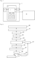
- FIG. 1 illustrates a general configuration of a principal part of an automatic operation device of a machining center in an embodiment of the present invention in the form of block diagram.
- the CNC device in the present embodiment has a basic configuration common to those of conventional CNC devices. A more specific description will be given.
- the CNC device 1 is installed on, for example, an outer wall surface of a guard encircling a machine tool body and a front face of the body of the CNC device is a control panel as shown in FIG. 5 .
- the control panel is provided with a touch panel-type liquid crystal display 11 as a displaying unit.
- the touch panel-type liquid crystal display 11 displays a menu screen in which items of various work operation modes for a machine tool provided in the CNC device 1 in advance are respectively shown as an icon 10.
- a USB port 12 is disposed in the vicinity of the display so that varied data can be inputted and outputted, and a keyboard 15 including a mouse pad 13 and a mouse button 14 is disposed below the display. Further, an operation panel 16 provided with switches and buttons related to various operations of a machine tool is provided in an area below the keyboard 15.
- the CNC device 1 is provided with a "CAD data-based automatic operation" mode as one of work operation modes and is so configured that an icon 10A of that item is also displayed in the menu screen. Therefore, the CAD data-based automatic operation mode can be selected and performed by touching the icon 10A.
- the CNC device 1 Under the control of a control unit 3, the CNC device 1 performs drive control on a machining unit of the machine tool 20 in accordance with a predetermined machining command and causes cutting operation to be performed on a material to be machined while sequentially changing and attaching a tool to a rotary main spindle in correspondence with each manufacturing process.
- a control unit 3 the CNC device 1 performs drive control on a machining unit of the machine tool 20 in accordance with a predetermined machining command and causes cutting operation to be performed on a material to be machined while sequentially changing and attaching a tool to a rotary main spindle in correspondence with each manufacturing process.
- Detailed illustration of the machine tool 20 will be omitted here.
- the control unit 3 of the CNC device 1 is provided with a storage unit 4, in which identification information corresponding to a large number of tools housed in a magazine or the like of the machine tool 20 and tool information 5 such as a type, a shape, a material, and the like of each tool, associated with the identification information are stored. Each tool is managed according to the identification information.
- the machine tool 20 is provided with an automatic tool changer (not shown), and a tool to be used is appropriately specified and changed and attached between the rotary main spindle of the machining unit and the magazine by the changer, with predetermined timing during automatic operation according to a machining program.
- the storage unit 4 is further provided with a learned model 6 generated based on enormous amount of past cutting operation data in advance.
- the learned model 6 was generated by learning machining data as machining conditions including a tool used and cutting conditions and a manufacturing process including a tool trajectory and a machining program with which the manufacturing process was performed, for each feature such as projections and depressions, distortions, holes, pockets, and slots, in faces subjected to various cutting operations, in correspondence with one another.
- the control unit 3 is provided with an automatic machining command generation unit 7 having: an automatic manufacturing process setting function of automatically setting a manufacturing process for forming features of a newly manufactured machined product by applying the features to the learned model 6; and a machining command generation function of automatically generating a machining command for causing the machine tool to perform the manufacturing process.
- the automatic machining command generation unit 7 has a feature extraction function of extracting each feature of a machined product based on acquired three-dimensional CAD design data of the machined product. That is, a feature of a machined product applied to the learned model 6 when a manufacturing process is set and a machining command is generated, is obtained from three-dimensional CAD design data of the machined product by the feature extraction function.
- the automatic manufacturing process setting function of the automatic machining command generation unit 7 further includes a function of: after each feature of the machined product is selected based on three-dimensional CAD design data of the machined product by the feature extraction function, forming a 3D model of the machined product and causing the liquid crystal display 11 to display the 3D model; and selecting one or more possible different mounting directions of the machined product and causing a 3D model in each selected mounting direction to be displayed on the display 11 in a selectable manner. An operator can select and determine the most suitable mounting direction from among those proposed and displayed. Therefore, automatic setting of a manufacturing process is forwarded based on the thus determined mounting direction.
- the automatic machining command generation unit 7 is provided with: a simulation function of causing a tool trajectory of an automatically generated manufacturing process to be displayed on the display 11 as 3D computer graphics, for example, animation moving images; and an interference detection function of, when interference occurs between a tool and a non-cutting area of a material to be machined or a peripheral member of the machining unit while moving images are being displayed, stopping the moving images and causing an interference alert to be displayed.
- the automatic machining command generation unit is also provided with a machining command improvement function of, at the time of an interference alert, altering the tool which caused the interference to a different tool and generating a machining command again.
- FIG. 2 is a flowchart illustrating a machining command generation process
- FIGS. 3(a) and 3(b) and FIGS. 4(a) and 4(b) are schematic diagrams illustrating an example of a screen shown on the display 11 at each step of an automatic manufacturing process setting process.
- the icon 10A corresponding to the "CAD data-based automatic operation" mode is selected in a menu screen displayed on the touch panel-type liquid crystal display 11 of the control panel by touching the icon.
- the CAD data-based automatic operation mode is started (100).
- three-dimensional CAD design data of the target machined product stored in USB is read (101) via a data acquisition unit 2, such as the USB port 12.
- a process of automatic machining command generation is substantially started.
- CAD data may be read from another computer via a computer network using wireless or wired communication, for example, Ethernet (registered trademark) communication.
- the automatic machining command generation unit 7 forms a 3D model of the machined product based on the three-dimensional CAD design data and causes the 3D model to be displayed on the display 11 (102) as illustrated in FIG. 3(a) , and extracts all the features (103). Further, the automatic machining command generation unit selects one or more possible mounting directions of the machined product and displays the 3D model on the display 11 in each selected mounting direction in a selectable and determinable manner.
- the external shape of the machined product is a pentagonal pyramidal prism (a shape obtained by mating a pentagonal pyramid with the upper face of a pentagonal prism) will be taken as an example.
- a mounting direction in which the center axis of the pentagonal pyramidal prism is perpendicular and a mounting direction in which the center axis is horizontal are selected.
- the horizontal mounting direction one of the side faces of the pentagonal prism portion will be selected as a mounting face.
- the mounting direction is determined (104).
- the bottom face of the pentagonal prism portion does not have a feature and does not require cutting. Therefore, a direction in which the bottom face provides a mounting face, that is, the mounting direction in which the center axis is perpendicular can be immediately determined to be practical and most suitable.
- the operator selects an automatic machining command generation start button P on the display 11 by touching the button, after selecting and determining this most suitable mounting direction of the machined product. Then, in the automatic machining command generation unit 7, based on the selected and determined mounting direction, substantial manufacturing process setting (105) is started. Specifically, by applying each feature extracted in advance to the learned model 6, a tool suitable for machining a respective feature is selected from tools registered in the tool information 5 in the storage unit 4 and various cutting conditions and machining conditions are determined. A tool trajectory is also determined based on the machining conditions. Then, a manufacturing process including specifying the tool required for cutting with respect to each feature, mounting the tool, and up to the tool trajectory is set.
- the automatic machining command generation unit 7 identifies the tool that causes the occurrence of interference and selects the second-best tool based on the learned model 6 to perform tool alteration (110). And the automatic machining command generation unit 7 newly determines machining conditions and a machining trajectory with the altered tool and re-sets the manufacturing processes (105). Then, a machining command is generated again (106) in correspondence with the improved manufacturing processes. The above process from the tool alteration to the machining command modification is repeated until the occurrence of interference is eliminated in a simulation; therefore, a machining command is improved by optimal tool and tool trajectory, a perfect machining command is easily generated in a short time.
- an operator need not prepare an NC program beforehand at much expense in time and effort and only has to input three-dimensional CAD design data of a machined product to the CNC device 1. Thereafter, the operator is required just to perform touch operation with predetermined icons and buttons on the touch panel-type liquid crystal display 11 as if the operator operated a smartphone. Then, a machining command is automatically generated and an automatic operation of the machining center is performed in accordance with the machining command; therefore, the intended machined product can be very easily manufactured.
Landscapes
- Engineering & Computer Science (AREA)
- Human Computer Interaction (AREA)
- Manufacturing & Machinery (AREA)
- Physics & Mathematics (AREA)
- General Physics & Mathematics (AREA)
- Automation & Control Theory (AREA)
- Numerical Control (AREA)
Description
- The present invention relates to an automatic operation device of a machining center equipped with a CNC device for machine tools in which time and trouble for a skilled hand to create a machining program using code for an NC language are saved and only by acquiring three-dimensional CAD design data of a machined product, a machining program is automatically created based on the data.
- With respect to present machine tools, especially, machining centers, a material is automatically cut in accordance with a predetermined NC machining program to form an intended product using a numerical control device, a so-called NC (Numerical Control) device.
- An NC machining program is created based on machining conditions, including a tool to be used and numeric data (NC data) such as a movement based on coordinate positions in X, Y, Z, and the like and a speed of the tool during machining with the tool and numerical control information on a manufacturing process. Presently, computer numerical control devices (CNC devices) have been used which is further automated by automatically calculating part of numerical control information, for example, correction of a tool diameter, interpolating operation, speed control, and the like with a built-in computer.
- Therefore, to create an NC machining program for obtaining a machined product in an intended shape by cutting a material to be machined via automatic operation of a machine tool, especially, a machining center, a machining condition and a manufacturing process for the program must be set beforehand.
- Each manufacturing process is determined based on a machining method for cutting each feature to be formed in a machined product. Features cite here refer to step heights of projections and depressions, surface shapes of curves, holes, pockets, slots, and the like in machined products. Usually, a tool suitable for forming these features is appropriately selected from, for example, various milling cutters suitable for facing, various drills suitable for drilling, various end mills suitable for grooving and shoulder grinding, and the like; a machining condition including a cutting condition is established; and a tool trajectory is determined based on the machining condition. Further, a manufacturing process including the above tool selection, tool change, and execution of a tool trajectory is established and an NC machining program corresponding to the manufacturing process is created.
- However, an NC machining program itself is created by an engineer using an NC language, such as G code and M code, based on a CAD (Computer Aided Design) design drawing of a machined product. In addition, in recent years, machining has been performed with a sophisticated machine tool, such as simultaneous up to five-axis (X, Y, Z, A, C) control. For this reason, complicated control in which these multiple axes will not interfere with one another is required. Therefore, an NC machining program is also created using CAM (Computer Aided Manufacturing) system based on a three-dimensional CAD diagram.
- Owing to CAM operation, code need not be directly manually inputted but a complicated machining program need be created through machining method consideration, tool selection, and machining condition determination by a skilled hand and is thus time-consuming.
- Consequently, a device that allows a machining program to be automatically created has been considered. For example,
Patent Literature 1 discloses an automatic program creation device in which a cutting condition is determined according to shape and attribute data from a data input unit, a tool path is determined in accordance with the cutting condition, and an NC machining program is created based on the tool path. -
- [PTL 1]
Japanese Patent Publication No. Hei 6(1994)-97413 - [PTL 2]
Japanese Unexamined Patent Application Publication No. Hei 11(1999)-129141 - [PTL 3]
Japanese Unexamined Patent Application Publication No. 2002-189510 - [PTL 4]
PCT International Publication No. WO 2015/096511 - [PTL 5]
U.S. Patent No.10338565 - [PTL 6]
U.S. Unexamined Patent Application Publication No. 2019/018391 - According to the technology in
Patent Literature 1, shape data and attribute data are inputted using a keyboard at a data input unit and a time-consuming, troublesome process of an engineer's input work is required. Further, what is created is just a standard NC machining program from an intermediate tool path data, and the technology requires editing operation of the program picked up in increments of one manufacturing process thereafter. That is, when a complicated special manufacturing process is included, time-consuming editing work by an engineer is still required. - Meanwhile, a different automatic machining information generation device has also been developed (Refer to Patent Literature 2). In this device, a region to be machined is extracted from CAD design data and a machining shape is determined; an applicable tool is selected from a tool database; a cutting speed, a feed speed, and the like are automatically calculated by reading a recommended machining speed and a recommended feed speed for this operation from a machining condition database; and then a tool trajectory is generated and a machining program is created.
- Further, a CAM system has also been considered (Refer to
Patent Literature 3, for example). In this CAM system, feature data for a machined product is extracted from CAD data and a manufacturing process and a machining area for each manufacturing process are established; material data and a machining model of each manufacturing process are generated; a tool path data is generated based on a tool database and a machining condition database and an NC machining program is then created. -
Patent Literature 4 discloses that an intelligent numerical control machining programming system and method for aircraft structural parts, the system employs an existing CAD/CAM system as a platform, being set up upon a three-dimensional model, and gives a comparatively systematical and accurate reflection of and also support to the professional procedures of the numerical control machining programming for aircraft structural parts. -
Patent Literature 5 discloses that methods and apparatus for training a set of regression machine learning models with a training set to produce a set of predictive values for a pending manufacturing request as methods and apparatus for machine learning predictions and multi-objective optimization of manufacturing processes, the training set including data extracted from a set of manufacturing transactions submitted by a set of entities of a supply chain, and a multi-objective optimization model is implemented to receive an input including the set of predictive values and a set of features of a physical object, and generate an output with a set of attributes associated with a manufacture of the physical object in response to receiving the input. -
Patent Literature 6 discloses that systems and method relating to machining parts include a CNC system, and a computer including a processor and a computer-readable medium, as method and system for processing machine data before completion of machining, wherein the computer-readable medium encodes instructions including receiving, at the computer program, output data from a CNC machine that receives instructions of a Numerical Control (NC) program at a computer of the CNC machine, the instructions causing the CNC machine to i) manufacture a part, and ii) output the output data, parsing, by the computer program, the output data before completion of the manufacturing of the part by the CNC machine in accordance with the instructions of the NC program, selecting, by the computer program and based on one or more predetermined parameters, a set of data from the parsed output data; and providing, by the computer program to a remote system, the set of data for processing to facilitate machining using the CNC machine. - However, to create a complicated NC machining program corresponding to such a manufacturing process that requires complicated control with a sophisticated machine tool such as simultaneous five-axis control for manufacture of a machined product having multiple diverse features, one night is taken even with a conventional CAM system capable of automatically creating a machining program. Presently, a system capable of efficiently and automatically creating such a complicated machining program in so short a time as approximately 10 minutes is not present. Of course, such a technology that such a system is provided in a CNC device for a machine tool and the machine tool is immediately caused to perform precision machining on the spot based on a created machining program is not present, either.
- In consideration of the above-mentioned problem, it is an object of the present invention to provide an automatic operation device of a machining center that enables automatic, immediate execution of a manufacturing process on the spot and simple manufacture of an intended machined product just by acquiring three-dimensional CAD design data of the machined product.
- To achieve the above object, the present invention is an automatic operation device of a machining center comprising a CNC device and a machine tool, wherein the CNC device is configured to be connected to the machine tool and to perform numerical control. The CNC device includes:
- a control unit provided with various work operation modes related to the machine tool in advance and having a function of causing a selected work operation mode to be performed;
- a displaying unit having a menu screen display function of displaying items corresponding to the work operation modes in a selectable manner and a function of chronologically displaying work operation information of a work operation mode being performed with respect to each selected item; and
- a storage unit storing identification information of multiple tools so housed that the tools can be changed and attached to a rotary main spindle of a machining unit of the machine tool via an automatic tool changer and tool information including the material and shape of each tool corresponding to the identification information.
- The control unit is configured to perform drive control on the machining unit of the machine tool in accordance with a predetermined machining program and to causes the material to be machined to be cut while changing and attaching tools to the rotary main spindle in correspondence with each manufacturing process.
- In this automatic operation device of a machining center,
- the control unit includes an automatic machining command generation unit that is configured to automatically generates a machining command for causing the machine tool to perform all the manufacturing processes for cutting the material to be machined based on three-dimensional CAD design data of an intended machined product, and
- the storage unit includes a learned model generated by learning, with respect to each feature subjected to various cutting operation, machining conditions including a tool used and cutting conditions when a relevant cutting operation was performed and machining data including a tool trajectory and an execution program for the trajectory in correspondence with each other in advance.
- The automatic machining command generation unit has:
a feature extraction function of extracting features to be subjected to a cutting operation from three-dimensional CAD design data of the machined product on the basis of the shape of the material to be machined, wherein the feature comprises step heights of projections and depressions, surface shapes of curves, holes, pockets and slots; an automatic manufacturing process setting function of automatically determining machining conditions required for cutting with respect to each feature and automatically setting a manufacturing process including a tool trajectory based on the machining conditions, by applying each extracted feature to the learned model; an all manufacturing process setting function of determining a procedure for performing manufacturing processes for all the features and setting a series of all the manufacturing processes required up to the finish of the machined product; and a machining command generation function of generating a machining command for causing the machine tool to perform all the set manufacturing processes based on the learned model. - The automatic manufacturing process setting function further includes a function of: generating a 3D model of the machined product based on the three-dimensional CAD design data and causing the displaying unit to display the 3D model; and selecting one or more different mounting directions in which the machined product can be mounted on the machining unit and the 3D model in each selected mounting direction to be displayed in a selectable manner and the manufacturing process for cutting each feature is automatically set based on the selected and determined mounting direction.
- The machining conditions cited in relation to the present invention are the same as machining conditions set on an ordinary machine tool. The machining conditions are conditions required for determining a manufacturing process and mainly includes a type and a shape of a tool, a diameter and a material of a tool, and cutting conditions including main spindle rotational speed, cutting feed, cutting width, a depth of cut (in Z direction) of a cutter, and the like as well as the properties of a material to be machined, a method for clamping with a machining unit jig, a clamp position, a mounting direction, and the like. A tool trajectory, a so-called tool path is determined for obtaining each intended cut feature based on these machining conditions.
- The CNC device can be caused to acquire three-dimensional CAD design data of an intended machined product stored in, for example, USB via a USB port. Alternatively, the CNC device can be caused to acquire three-dimensional CAD design data of the intended machined product from another computer on a computer network via network communication.
- According to the above-mentioned configuration of the present invention, in the automatic machining command generation unit of the control unit, features to be formed by cutting are extracted on the basis of a shape of a material to be machined based on three-dimensional CAD design data of an intended machined product acquired as mentioned above; machining conditions for each feature are automatically determined by applying the feature to the learned model stored in the storage unit; a tool to be used and a tool trajectory are determined based on the machining conditions; and a manufacturing process including specifying and changing the tool and up to execution of the tool trajectory is automatically set. Further, a procedure for performing the manufacturing processes for all the features is determined and a series of all the manufacturing processes is set; and a machining command for causing the machine tool to perform all the set manufacturing processes is efficiently and automatically set based on the learned model. Therefore, an operator's necessity for creating an NC program in advance is obviated and the machined product is automatically and immediately manufactured on the spot only by inputting three-dimensional CAD design data to the CNC device.
- The learned model is obtained by learning machining conditions including a tool used and cutting conditions and machining data including a tool trajectory and an execution program for the trajectory for each of various features with respect to an enormous amount of past cutting operation data accumulated by the present inventors et al. That is, the learned model is obtained by learning all the pieces of data required for cutting each feature in correspondence with one another. Therefore, machining conditions required for cutting features for the manufacture of a new machined product and a manufacturing process including a tool trajectory based on the machining conditions are automatically determined and set in a short time based on the learned model. Further, a machining command for causing the machine tool to perform the manufacturing process is also immediately and automatically generated.
- The machining command for causing the machine tool to perform the set manufacturing process may, of course, be an NC program as before. However, the present invention is not limited to a program using such an NC language as G code and any other machining program or any command signal that enables direct drive control on the machine tool may be utilized as long as the set manufacturing process can be performed.
- Execution of a manufacturing process with a machine tool is substantially achieved by performing a tool trajectory with a specified tool. This execution of a tool trajectory is implemented by relative linear movement or rotational movement between the tool side and a table or the like on the work side caused by motor drive in each axis. That is, a tool trajectory is performed by drive control on a motor in each axis. More specifically, according to an ordinary NC program, each motor is driven by a pulse train signal obtained by read NC data being converted at an information processing circuit. The pulse train signal instructs actual tool movement by a motor rotation angle corresponding to a number of pulses of the signal, that is, position control and further instructs an actual tool moving speed by rotational speed control on a motor corresponding to a pulse frequency. Therefore, execution of a tool trajectory can be achieved by using a corresponding pulse train signal to directly instruct each motor without intervention of an NC program.
- Consequently, the machining command for performing the set manufacturing process according to the present invention may include such a command signal that directly controls driving of each motor. For example, execution of a series of manufacturing processes can be instructed by what is configured by combining a pulse train signal controlling driving of a motor in each axis corresponding to a tool trajectory with a command signal for tool specification and tool change. A pulse train signal itself can be simply generated based on a pulse train signal which has been used in correspondence with various tool trajectories included in machining data learned when the learned model is generated in advance.
- In conventional NC programs created using G code or M code, a very large number of interpolating functions are used. Meanwhile, when a direct command signal without intervention of an NC program is generated and used as a machining command for performing an automatically set manufacturing process, these interpolating functions are omitted; therefore, reduction of a machining time and enhancement of machining accuracy can be achieved. By performing positioning by actually set actual values, not by feedback control, thermal displacement is eliminated and real-time control free from a delay to a command in servo control is implemented. Therefore, any load fluctuation can be instantaneously coped with and as a result, significant reduction of a machining time and enhancement of accuracy can be achieved.
- The machining conditions and the tool trajectory for setting the manufacturing process are determined based on a cutting direction of each feature and these cutting directions are determined according to an orientation of the machined product at the time of final completion of cutting. Therefore, the orientation of the machined product, that is, a direction of mounting to a machining unit is determined before the machining conditions and the tool trajectory are determined by the automatic manufacturing process setting function of the automatic machining command generation unit.
- Consequently, according to the present invention, the automatic manufacturing process setting function is further provided with a function of first generating a 3D model of the machined product based on the three-dimensional CAD design data to cause the displaying unit of the CNC device to display the 3D model and selecting one or more different mounting direction in which the machined product is mounted on the machining unit and displaying the 3D model in each selected mounting direction in a selectable manner. By selecting and determining one that provides the most practical and efficient manufacturing process from among the automatically proposed and displayed different mounting directions, an efficient machining command is automatically generated based on that mounting direction.
- As one or more automatically proposed different mounting directions, first, one that can be taken as a mounting direction of the relevant machined product only has to be selected based on the three-dimensional CAD design data. For example, by setting a center axis of a machined product from an external shape of the product, a mounting direction in which an orientation of the center axis is changed can be selected. Specifically, first, a mounting direction in which the center axis is perpendicular and a mounting direction in which the center axis is horizontal can be selected. Aside from the foregoing, a mounting direction in which the center axis is tilted is also selectable depending on an external shape of a machined product. Then, by selecting a relatively large face that can provide a mounting face with respect to each orientation of the center axis, a possible placement direction can also be respectively determined. Therefore, when a possible mounting direction of a machined product is only selected based on the three-dimensional CAD design data as mentioned above, multiple mounting directions can be displayed as a 3D model in a very short time. As mentioned above, the most suitable one can be selected from among these automatically displayed mounting directions.
- Since a machined product often includes at least one face where a cut feature is usually not formed, taking such a face having no feature, that is, a face that does not require cutting as a mounting face is practical. Therefore, an operator can instantaneously select, as the most suitable mounting direction, a mounting direction in which a face of the machined product requiring no cutting provides a mounting face by checking a 3D model in one or more proposed mounting directions on a display. When one or more faces where a feature is not formed and which can provide a mounting face are present, an operator can easily determine a face to be a mounting face in a short time from mounting stability and the like based on the shapes of a fixing jig, the machined product, and a material to be machined without complicated computation by a computer.
- As mentioned above, according to the present invention, by causing the CNC device to acquire three-dimensional CAD design data of a machined product, first, one or more possible mounting directions for the product are automatically selected and displayed. By merely selecting and determining the most suitable one from among these mounting directions, a machining command that enables execution of all the manufacturing processes up to obtaining the machined product from a material to be machined based on the mounting direction is automatically generated in a short time based on the learned model. Therefore, an operator can cause precision machining to be performed on the material to be machined fixed on the machining unit of the machine tool in a state corresponding to the mounting direction in accordance with the automatically generated machining command just by triggering a cycle start.
- Therefore, an operator need not prepare an NC program in advance and thus need not have knowledge about such an NC language as G code or M code or experience about machining conditions associated with various features. Only with three-dimensional CAD design data, a machined product can be simply, efficiently, and automatically manufactured just by inputting the data to the CNC device.
- In addition, the automatic machining command generation unit is preferably provided with a simulation function for automatically verifying whether the tool trajectory of the set manufacturing process enables smooth machining without interference or not and an interference detection function.
- The simulation function causes the displaying unit to display a tool trajectory of a specified tool in a set manufacturing process as 3D computer graphic moving images, for example, animation moving images. The interference detection function stops moving images and causes an interference alert to be displayed when interference occurs between a tool and a non-cutting area of a material to be machined or a peripheral member of the machining unit while the moving images are being displayed. An operator can check the presence or absence of interference with respect to a tool trajectory of a specific tool while checking moving images and, when an interference alert is displayed, can simply understand that a machining command generated based on the tool trajectory must be modified.
- Consequently, by additionally providing the automatic machining command generation unit with a machining command improvement function of, at the time of occurrence of an interference alert, altering the tool with interference to another tool and causing a machining command to be automatically generated again, the automatically generated machining command can be made completely safe. With this machining command improvement function, machining conditions and a tool trajectory based on the machining conditions are newly determined in accordance with the altered tool and an improved manufacturing process is automatically set. Further, an improved machining command corresponding to the thus improved manufacturing process is automatically generated and a simulation process is repeated until interference is eliminated. As a result, a machining command for a manufacturing process in which a tool trajectory is performed without interference are automatically generated without need for time-consuming verification or the like by a skilled hand; therefore, an operator can easily perform perfect product machining in a short time with peace of mind.
- The displaying unit according to the present invention may be a liquid crystal display or the like conventionally provided in a CNC device. Especially adopting a touch panel type is desirable because a work operation mode can be selected or performed on a display in a shorter time and easily. In this case, when items of various work operation modes are displayed as icons in a menu screen in a selectable and executable manner, workability is further enhanced.
- In this case, an item of "CAD data-based automatic operation for machining center" mode from input of the above-mentioned three-dimensional CAD design data to automatic generation and execution of a machining command is displayed as an icon in a menu screen. As a result, an operator can trigger the "CAD data-based automatic operation for machining center" mode just by touching the icon. And then, the operator only has to perform touch operation only when a mounting direction is selected and determined immediately after three-dimensional CAD design data is read and when a complete machining command generated immediately after is started. Thus, the operator can easily perform manufacture of an intended machined product in a short time as if the operator operated a smartphone.
- According to the CAD data-based automatic operation device of a machining center of the present invention, as described up to this point, the following effect is brought about: By causing three-dimensional CAD design data of an intended machined product to be acquired, possible mounting directions are immediately proposed through a 3D model display in a selectable manner and the most suitable mounting direction can be selected and determined. Based on the determined mounting direction, extracted features are applied to a learned model and a machining command causing a machine tool to perform all the manufacturing processes required for obtaining the machined product in a short time is automatically generated. For this reason, only with three-dimensional CAD design data of a machined product, an operator can immediately, on the spot, cause the machining center to automatically operate in accordance with the automatically generated machining command without need for skilled-labor's knowledge. Thus, the intended machined product can be simply manufactured in a short time.
-
-
FIG. 1 is a block diagram schematically illustrating a configuration of a principal part of a CAD data-based automatic operation device of a machining center in an embodiment of the present invention; -
FIG. 2 is a flowchart illustrating a process of machining command generation by the automatic machining command generation unit inFIG. 1 ; -
FIG. 3(a) is a schematic diagram illustrating an example of a screen in which a 3D model of a machined product in the machining command generation process shown inFIG. 2 and shows a 3D model display screen that appears immediately after three-dimensional CAD design data of a target machined product is selected and read; -
FIG. 3(b) is a schematic diagram illustrating an example of a screen in which a 3D model of a machined product in the machining command generation process shown inFIG. 2 and shows a display screen that appears when one of 3D models displayed in proposed different mounting directions is selected; -
FIG. 4(a) is a schematic diagram illustrating an example of a screen in which animation moving images are displayed during a tool trajectory simulation and shows a display screen that appears when the simulation is in progress; -
FIG. 4(b) is a schematic diagram illustrating an example of a screen in which animation moving images are displayed during a tool trajectory simulation and shows a display screen that appears when the simulation ends; and -
FIG. 5 is a schematic front view illustrating a basic configuration of a control panel of a CNC device. -
FIG. 1 illustrates a general configuration of a principal part of an automatic operation device of a machining center in an embodiment of the present invention in the form of block diagram. The CNC device in the present embodiment has a basic configuration common to those of conventional CNC devices. A more specific description will be given. TheCNC device 1 is installed on, for example, an outer wall surface of a guard encircling a machine tool body and a front face of the body of the CNC device is a control panel as shown inFIG. 5 . The control panel is provided with a touch panel-typeliquid crystal display 11 as a displaying unit. The touch panel-typeliquid crystal display 11 displays a menu screen in which items of various work operation modes for a machine tool provided in theCNC device 1 in advance are respectively shown as anicon 10. - A
USB port 12 is disposed in the vicinity of the display so that varied data can be inputted and outputted, and akeyboard 15 including amouse pad 13 and amouse button 14 is disposed below the display. Further, anoperation panel 16 provided with switches and buttons related to various operations of a machine tool is provided in an area below thekeyboard 15. - The
CNC device 1 according to the present embodiment is provided with a "CAD data-based automatic operation" mode as one of work operation modes and is so configured that anicon 10A of that item is also displayed in the menu screen. Therefore, the CAD data-based automatic operation mode can be selected and performed by touching theicon 10A. - Under the control of a
control unit 3, theCNC device 1 performs drive control on a machining unit of themachine tool 20 in accordance with a predetermined machining command and causes cutting operation to be performed on a material to be machined while sequentially changing and attaching a tool to a rotary main spindle in correspondence with each manufacturing process. Detailed illustration of themachine tool 20 will be omitted here. - As shown in
FIG. 1 , thecontrol unit 3 of theCNC device 1 is provided with astorage unit 4, in which identification information corresponding to a large number of tools housed in a magazine or the like of themachine tool 20 andtool information 5 such as a type, a shape, a material, and the like of each tool, associated with the identification information are stored. Each tool is managed according to the identification information. Meanwhile, themachine tool 20 is provided with an automatic tool changer (not shown), and a tool to be used is appropriately specified and changed and attached between the rotary main spindle of the machining unit and the magazine by the changer, with predetermined timing during automatic operation according to a machining program. - The
storage unit 4 is further provided with a learnedmodel 6 generated based on enormous amount of past cutting operation data in advance. The learnedmodel 6 was generated by learning machining data as machining conditions including a tool used and cutting conditions and a manufacturing process including a tool trajectory and a machining program with which the manufacturing process was performed, for each feature such as projections and depressions, distortions, holes, pockets, and slots, in faces subjected to various cutting operations, in correspondence with one another. - In the present embodiment, further, the
control unit 3 is provided with an automatic machiningcommand generation unit 7 having: an automatic manufacturing process setting function of automatically setting a manufacturing process for forming features of a newly manufactured machined product by applying the features to the learnedmodel 6; and a machining command generation function of automatically generating a machining command for causing the machine tool to perform the manufacturing process. In addition, the automatic machiningcommand generation unit 7 has a feature extraction function of extracting each feature of a machined product based on acquired three-dimensional CAD design data of the machined product. That is, a feature of a machined product applied to the learnedmodel 6 when a manufacturing process is set and a machining command is generated, is obtained from three-dimensional CAD design data of the machined product by the feature extraction function. - The automatic manufacturing process setting function of the automatic machining
command generation unit 7 further includes a function of: after each feature of the machined product is selected based on three-dimensional CAD design data of the machined product by the feature extraction function, forming a 3D model of the machined product and causing theliquid crystal display 11 to display the 3D model; and selecting one or more possible different mounting directions of the machined product and causing a 3D model in each selected mounting direction to be displayed on thedisplay 11 in a selectable manner. An operator can select and determine the most suitable mounting direction from among those proposed and displayed. Therefore, automatic setting of a manufacturing process is forwarded based on the thus determined mounting direction. - In the present embodiment, further, the automatic machining
command generation unit 7 is provided with: a simulation function of causing a tool trajectory of an automatically generated manufacturing process to be displayed on thedisplay 11 as 3D computer graphics, for example, animation moving images; and an interference detection function of, when interference occurs between a tool and a non-cutting area of a material to be machined or a peripheral member of the machining unit while moving images are being displayed, stopping the moving images and causing an interference alert to be displayed. The automatic machining command generation unit is also provided with a machining command improvement function of, at the time of an interference alert, altering the tool which caused the interference to a different tool and generating a machining command again. - Hence by automatically repeating the above-mentioned simulation process and improvement of a machining command until interference is eliminated with respect to all the tool trajectories, a machining command with a perfect tool trajectory can be easily obtained in a short time without time-consuming verification by a skilled hand.
- With respect to the
CNC device 1 having the above-mentioned configuration, processes from automatic generation of a machining command based on three-dimensional CAD design data of an intended machined product to execution of an automatic operation of a machining center will be described below.FIG. 2 is a flowchart illustrating a machining command generation process; andFIGS. 3(a) and 3(b) andFIGS. 4(a) and 4(b) are schematic diagrams illustrating an example of a screen shown on thedisplay 11 at each step of an automatic manufacturing process setting process. - First, the
icon 10A corresponding to the "CAD data-based automatic operation" mode is selected in a menu screen displayed on the touch panel-typeliquid crystal display 11 of the control panel by touching the icon. Thus, the CAD data-based automatic operation mode is started (100). Subsequently, three-dimensional CAD design data of the target machined product stored in USB is read (101) via adata acquisition unit 2, such as theUSB port 12. As a result, a process of automatic machining command generation is substantially started. CAD data may be read from another computer via a computer network using wireless or wired communication, for example, Ethernet (registered trademark) communication. - The automatic machining
command generation unit 7 forms a 3D model of the machined product based on the three-dimensional CAD design data and causes the 3D model to be displayed on the display 11 (102) as illustrated inFIG. 3(a) , and extracts all the features (103). Further, the automatic machining command generation unit selects one or more possible mounting directions of the machined product and displays the 3D model on thedisplay 11 in each selected mounting direction in a selectable and determinable manner. Here, a case where the external shape of the machined product is a pentagonal pyramidal prism (a shape obtained by mating a pentagonal pyramid with the upper face of a pentagonal prism) will be taken as an example. In this case, a mounting direction in which the center axis of the pentagonal pyramidal prism is perpendicular and a mounting direction in which the center axis is horizontal are selected. However, in the case of the horizontal mounting direction, one of the side faces of the pentagonal prism portion will be selected as a mounting face. - When the operator touches and selects one in a mounting direction determined to be most suitable from among the displayed 3D models in the different mounting directions on the
display 11 as shown inFIG. 3 (b) , the mounting direction is determined (104). In the case of the above pentagonal pyramidal prism, the bottom face of the pentagonal prism portion does not have a feature and does not require cutting. Therefore, a direction in which the bottom face provides a mounting face, that is, the mounting direction in which the center axis is perpendicular can be immediately determined to be practical and most suitable. - The operator selects an automatic machining command generation start button P on the
display 11 by touching the button, after selecting and determining this most suitable mounting direction of the machined product. Then, in the automatic machiningcommand generation unit 7, based on the selected and determined mounting direction, substantial manufacturing process setting (105) is started. Specifically, by applying each feature extracted in advance to the learnedmodel 6, a tool suitable for machining a respective feature is selected from tools registered in thetool information 5 in thestorage unit 4 and various cutting conditions and machining conditions are determined. A tool trajectory is also determined based on the machining conditions. Then, a manufacturing process including specifying the tool required for cutting with respect to each feature, mounting the tool, and up to the tool trajectory is set. When multiple kinds of features are present, an efficient procedure for manufacturing processes corresponding to all the features is determined and a series of all the manufacturing processes required for manufacturing the intended machined product is set. Thereafter, a machining command for causing the machine tool to perform all the set manufacturing processes is generated (106) immediately. - When setting of the manufacturing processes (105) and generation of the machining command (106) are completed, a simulation of tool trajectories for the set manufacturing processes is started (107) immediately and such 3D animation moving images as shown in
FIG. 4(a) are displayed on thedisplay 11. In this display of the moving images, the presence or absence of interference between a tool and a non- cutting area of the material to be machined or a peripheral member of the machining unit of the machine tool is detected (108) along the tool trajectory. When interference does not occur and simulation moving images of the tool trajectory are not stopped at some midpoint as shown inFIG. 4(b) and completes to the end, the manufacturing process and the machining command set and generated based on that tool trajectory can be securely determined to be free from interference with themachine tool 20 and be practicable. In this case, when the material to be machined is fixed on the machining unit in a direction corresponding to the mounting direction of the machined product selected and determined when the 3D model was displayed, the operator only has to operate a cycle start button S on thedisplay 11 by touching the button. Thus, a cycle start (111) is immediately triggered on the spot according to the generated machining command so that manufacture of the machined product can be forwarded. - Meanwhile, when interference occurs during a simulation, moving images are stopped and an interference alert is displayed (109). After the interference alert is displayed, the automatic machining
command generation unit 7 identifies the tool that causes the occurrence of interference and selects the second-best tool based on the learnedmodel 6 to perform tool alteration (110). And the automatic machiningcommand generation unit 7 newly determines machining conditions and a machining trajectory with the altered tool and re-sets the manufacturing processes (105). Then, a machining command is generated again (106) in correspondence with the improved manufacturing processes. The above process from the tool alteration to the machining command modification is repeated until the occurrence of interference is eliminated in a simulation; therefore, a machining command is improved by optimal tool and tool trajectory, a perfect machining command is easily generated in a short time. - When the manufacturing processes and the machining command are improved and simulation moving images with the improved tool trajectory completes to the end without being stopped by an occurrence of interference and the manufacturing processes and machining command based on that tool trajectory are determined to have become free from a problem and perfect, the operator only has to operate the button S on the
display 11 by touching the button. Then, a cycle start (111) of the manufacturing processes according to the improved and perfect machining command is triggered and manufacture of the machined product is performed on the machine tool. With theCNC device 1 in the present embodiment, it took only approximately 10 minutes to perform operations from reading of three-dimensional CAD design data of a machined product to generation of a perfect machining command by way of a simulation unlike conventional CAM systems, in which it used to take one night to automatically create a program. - As described up to this point, according to an automatic operation device of a machining center in the present embodiment, an operator need not prepare an NC program beforehand at much expense in time and effort and only has to input three-dimensional CAD design data of a machined product to the
CNC device 1. Thereafter, the operator is required just to perform touch operation with predetermined icons and buttons on the touch panel-typeliquid crystal display 11 as if the operator operated a smartphone. Then, a machining command is automatically generated and an automatic operation of the machining center is performed in accordance with the machining command; therefore, the intended machined product can be very easily manufactured. -
- 1: CNC device
- 2: Data acquisition unit
- 3: Control unit
- 4: Storage unit
- 5: Tool information
- 6: Learned model
- 7: Automatic machining command generation unit
- 10, 10A: Icon
- 11: Touch panel-type liquid crystal display
- 12: USB port
- 13: Mouse pad
- 14: Mouse button
- 15: Keyboard
- 16: Operation panel
- 20: Machine tool
- P: Automatic machining command generation start button
- S: Cycle start button
Claims (3)
- An automatic operation device of a machining center wherein the automatic operation device comprises a Computer Numerical Control, CNC, device (1) and a machine tool (20), and
wherein the CNC device is configured to be connected to the machine tool and to perform numerical control,
wherein the CNC device (1) includes:a control unit (3) provided with various work operation modes related to the machine tool in advance and having a function of causing a selected work operation mode to be performed;a displaying unit (11) having: a menu screen display function of displaying items corresponding to the work operation modes in a selectable manner; and a function of chronologically displaying work operation information of a work operation mode being performed with respect to each selected item; anda storage unit (4) storing: identification information of a plurality of tools so housed that the tools can be changed and attached to a rotary main spindle of a machining unit of the machine tool (20) via an automatic tool changer; and tool information (5) including the material and shape of each tool corresponding to the identification information,wherein the control unit (3) is configured to performs drive control on the machining unit of the machine tool (20) in accordance with a predetermined machining program and to causes cutting operation on the material to be machined to be performed while changing and attaching a tool to the rotary main spindle in correspondence with each manufacturing process,the automatic operation device being characterized in thatthe control unit (3) is provided with an automatic machining command generation unit (7) that is configured to automatically generates a machining command for causing the machine tool (20) to perform all the manufacturing processes for cutting the material to be machined based on three-dimensional CAD design data of an intended machined product,wherein the storage unit (4) includes a learned model (6) generated by, with respect to each feature subjected to various cutting operations, learning machining conditions including a tool used and cutting conditions when a relevant cutting operation was performed and machining data including a tool trajectory and an execution program for the trajectory in correspondence with each other beforehand,wherein the automatic machining command generation unit (7) is provided with:a feature extraction function of extracting features to be subjected to a cutting operation from three-dimensional CAD design data of the machined product on the basis of the shape of the material to be machined, wherein the feature comprises step heights of projections and depressions, surface shapes of curves, holes, pockets and slots; an automatic manufacturing process setting function of automatically determining machining conditions required for cutting with respect to each feature and automatically setting a manufacturing process including a tool trajectory based on those machining conditions, by applying each extracted feature to the learned model (6); an all manufacturing process setting function of determining a procedure for performing manufacturing processes for all the features and setting a series of all the manufacturing processes required up to the finish of the machined product; and a machining command generation function of generating a machining command for causing the machine tool (20) to perform all the set manufacturing processes based on the learned model (6), andwherein the automatic manufacturing process setting function further includes a function of: generating a 3D model of the machined product based on the three-dimensional CAD design data and causing the displaying unit (11) to display the 3D model; and selecting one or more different mounting directions in which the machined product can be mounted on the machining unit and causing the 3D model in each selected mounting direction to be displayed in a selectable manner and the manufacturing process for cutting each feature is automatically set based on the selected and determined mounting direction. - The automatic operation device according to Claim 1,
wherein the automatic machining command generation unit (7) is further provided with:a simulation function of causing the displaying unit (11) to display a tool trajectory for a set manufacturing process as a 3D computer graphics moving image;an interference detection function of, when interference occurs between a tool and a non-cutting area of a material to be machined or a peripheral member of the machining unit while the moving images are being displayed, stopping the moving image and displaying an interference alert; anda machining command improvement function of, at the time of an interference alert, altering the tool which caused the interference to a different tool, determining a tool trajectory based on machining conditions corresponding to the altered tool to re-set a manufacturing process, and generating an improved machining command. - The automatic operation device according to Claim 1 or 2,wherein the displaying unit is a touch panel-type display (11) installed on the front face of the CNC device (1) and has a function of respectively displaying items of each of the various work operation modes as icons in the menu screen in a selectable and executable manner, andwherein the displaying unit (11) is provided as one of the icons (10,10A) with an item corresponding to "a CAD data-based automatic operation for the machining center" mode, in which the automatic machining command generation unit (7) generates the machining command for causing the machine tool (20) to perform automatic operation based on the three-dimensional CAD design data through application to the learned model (6).
Applications Claiming Priority (2)
| Application Number | Priority Date | Filing Date | Title |
|---|---|---|---|
| JP2019161961A JP6719790B1 (en) | 2019-09-05 | 2019-09-05 | Automatic operation device for machining center based on CAD data |
| PCT/JP2019/042349 WO2021044641A1 (en) | 2019-09-05 | 2019-10-29 | Device for automatically operating machining center using cad data |
Publications (3)
| Publication Number | Publication Date |
|---|---|
| EP3816745A1 EP3816745A1 (en) | 2021-05-05 |
| EP3816745A4 EP3816745A4 (en) | 2021-11-24 |
| EP3816745B1 true EP3816745B1 (en) | 2024-01-24 |
Family
ID=71402382
Family Applications (1)
| Application Number | Title | Priority Date | Filing Date |
|---|---|---|---|
| EP19918498.7A Active EP3816745B1 (en) | 2019-09-05 | 2019-10-29 | Device for automatically operating machining center using cad data |
Country Status (4)
| Country | Link |
|---|---|
| US (1) | US11947332B2 (en) |
| EP (1) | EP3816745B1 (en) |
| JP (1) | JP6719790B1 (en) |
| WO (1) | WO2021044641A1 (en) |
Families Citing this family (7)
| Publication number | Priority date | Publication date | Assignee | Title |
|---|---|---|---|---|
| EP3945381A1 (en) * | 2020-07-31 | 2022-02-02 | Siemens Aktiengesellschaft | Production of surfaces determinable by means of cone segments using a machine tool |
| WO2023007581A1 (en) * | 2021-07-27 | 2023-02-02 | ファナック株式会社 | Numerical control device |
| JP7296672B2 (en) * | 2021-08-11 | 2023-06-23 | キタムラ機械株式会社 | Automatic operation system for machining center |
| JP7154514B1 (en) | 2021-08-11 | 2022-10-18 | キタムラ機械株式会社 | Automatic operation system for machining centers |
| WO2024095479A1 (en) * | 2022-11-04 | 2024-05-10 | 三菱電機株式会社 | Machining program generation device and machining program generation method |
| CN117300729B (en) * | 2023-10-12 | 2024-04-30 | 山东润龙精密机床有限公司 | Efficient and precise machining method for normal round holes of special-shaped products based on three-axis machine tool |
| CN117170306B (en) * | 2023-10-31 | 2024-03-15 | 成都飞机工业(集团)有限责任公司 | Cutter state monitoring method, cutter state monitoring system, electronic equipment and storage medium |
Family Cites Families (19)
| Publication number | Priority date | Publication date | Assignee | Title |
|---|---|---|---|---|
| JPH0697413A (en) | 1992-09-10 | 1994-04-08 | Hitachi Ltd | Solid-state image sensing element |
| WO1994008751A1 (en) * | 1992-10-09 | 1994-04-28 | Omron Corporation | Machining information determining system and method, and machining process information determining system and method |
| JPH11129141A (en) | 1997-10-31 | 1999-05-18 | Toyota Motor Corp | Automatic processing and evaluating device for machining information |
| JP2000084794A (en) | 1998-09-14 | 2000-03-28 | Makino Milling Mach Co Ltd | Machining device |
| US6728221B1 (en) | 1999-04-09 | 2004-04-27 | Siemens Information & Communication Networks, Inc. | Method and apparatus for efficiently utilizing conference bridge capacity |
| JP2002189510A (en) * | 2000-12-22 | 2002-07-05 | Mori Seiki Co Ltd | Working relevant information preparation device and numerical controller equipped with the same device |
| SI21200A (en) * | 2002-03-27 | 2003-10-31 | Jože Balič | The CNC control unit for controlling processing centres with learning ability |
| JP4300275B2 (en) | 2004-10-21 | 2009-07-22 | 義昭 垣野 | Process design method, process design apparatus, and computer program |
| DE102005045028A1 (en) * | 2005-09-12 | 2007-03-22 | Index-Werke Gmbh & Co. Kg Hahn & Tessky | simulation system |
| WO2009028056A1 (en) * | 2007-08-29 | 2009-03-05 | Mitsubishi Electric Corporation | Nc program generating device and nc program generating method |
| JP5890907B2 (en) | 2012-09-21 | 2016-03-22 | 株式会社日立製作所 | Machining process determination method and machining process design apparatus |
| CN103699055B (en) | 2013-12-24 | 2016-08-17 | 沈阳飞机工业(集团)有限公司 | Aircraft structure intelligent numerical control machining prgraming system and method |
| JP6063013B1 (en) * | 2015-08-27 | 2017-01-18 | ファナック株式会社 | Numerical control device with machining condition adjustment function to suppress chatter or tool wear / breakage |
| WO2018123116A1 (en) * | 2016-12-26 | 2018-07-05 | 三菱電機株式会社 | Manufacturing process generation device, manufacturing process generation method and program |
| US10452052B2 (en) * | 2017-07-13 | 2019-10-22 | Autodesk, Inc. | Method and system for processing machine data before completion of machining |
| US10061300B1 (en) * | 2017-09-29 | 2018-08-28 | Xometry, Inc. | Methods and apparatus for machine learning predictions and multi-objective optimization of manufacturing processes |
| JP7126360B2 (en) * | 2018-03-01 | 2022-08-26 | 株式会社牧野フライス製作所 | Method and apparatus for generating toolpaths |
| JP6740279B2 (en) * | 2018-04-13 | 2020-08-12 | ファナック株式会社 | Adjusting device and adjusting method |
| JP6784722B2 (en) * | 2018-06-28 | 2020-11-11 | ファナック株式会社 | Output device, control device, and evaluation function value output method |
-
2019
- 2019-09-05 JP JP2019161961A patent/JP6719790B1/en active Active
- 2019-10-29 WO PCT/JP2019/042349 patent/WO2021044641A1/en unknown
- 2019-10-29 US US17/252,829 patent/US11947332B2/en active Active
- 2019-10-29 EP EP19918498.7A patent/EP3816745B1/en active Active
Also Published As
| Publication number | Publication date |
|---|---|
| JP6719790B1 (en) | 2020-07-08 |
| US20220317656A1 (en) | 2022-10-06 |
| EP3816745A4 (en) | 2021-11-24 |
| US11947332B2 (en) | 2024-04-02 |
| WO2021044641A1 (en) | 2021-03-11 |
| EP3816745A1 (en) | 2021-05-05 |
| JP2021039657A (en) | 2021-03-11 |
Similar Documents
| Publication | Publication Date | Title |
|---|---|---|
| EP3816745B1 (en) | Device for automatically operating machining center using cad data | |
| EP3214514B1 (en) | Machine tool control method and machine tool control device | |
| US5465215A (en) | Numerical control method and apparatus | |
| EP1769296B1 (en) | Method for generating a cnc machine tool control program | |
| CN110610012A (en) | Processing based on policies selected from a database | |
| US5327350A (en) | Interactive type numerical control apparatus and method thereof | |
| JPH0457008B2 (en) | ||
| JP6638979B2 (en) | Numerical control device with machining process management function and machining process management program | |
| KR101468751B1 (en) | Numerical control system having graphic-based user interface | |
| EP4260976A1 (en) | Machining center automatic operating system | |
| JP2002529843A5 (en) | ||
| EP0509102A1 (en) | Method of working simulation | |
| KR102633846B1 (en) | Automatic Lathe Control System and the method for Productivity Improvement of Multi-Variety Small Volume Products | |
| JPH06119031A (en) | Nc data generating method for working of cut remaining part | |
| US20240134351A1 (en) | Machining center automatic operating system | |
| US5583409A (en) | Numerical control apparatus and method for controlling a machine | |
| JPH0750407B2 (en) | Numerical control system | |
| EP0519077A1 (en) | Conversational type numerical control device | |
| JP7296672B2 (en) | Automatic operation system for machining center | |
| JP2895685B2 (en) | Numerical control unit | |
| JP2003295917A (en) | Machining control device | |
| EP0543013B1 (en) | Method of preparing program for rough working | |
| JPH05237741A (en) | Nc data originating method | |
| JPS61257740A (en) | Tool selection system | |
| JPH0695293B2 (en) | Machining simulation method in numerical controller |
Legal Events
| Date | Code | Title | Description |
|---|---|---|---|
| STAA | Information on the status of an ep patent application or granted ep patent |
Free format text: STATUS: UNKNOWN |
|
| STAA | Information on the status of an ep patent application or granted ep patent |
Free format text: STATUS: THE INTERNATIONAL PUBLICATION HAS BEEN MADE |
|
| PUAI | Public reference made under article 153(3) epc to a published international application that has entered the european phase |
Free format text: ORIGINAL CODE: 0009012 |
|
| STAA | Information on the status of an ep patent application or granted ep patent |
Free format text: STATUS: REQUEST FOR EXAMINATION WAS MADE |
|
| 17P | Request for examination filed |
Effective date: 20200917 |
|
| AK | Designated contracting states |
Kind code of ref document: A1 Designated state(s): AL AT BE BG CH CY CZ DE DK EE ES FI FR GB GR HR HU IE IS IT LI LT LU LV MC MK MT NL NO PL PT RO RS SE SI SK SM TR |
|
| RIN1 | Information on inventor provided before grant (corrected) |
Inventor name: KITAMURA AKIHIRO Inventor name: KITAMURA KOSAKU Inventor name: ASANO TAKASHI Inventor name: AMAIKE SEIJI |
|
| A4 | Supplementary search report drawn up and despatched |
Effective date: 20211022 |
|
| RIC1 | Information provided on ipc code assigned before grant |
Ipc: G05B 19/4068 20060101ALI20211018BHEP Ipc: G05B 19/4155 20060101ALI20211018BHEP Ipc: G05B 19/4097 20060101AFI20211018BHEP |
|
| STAA | Information on the status of an ep patent application or granted ep patent |
Free format text: STATUS: EXAMINATION IS IN PROGRESS |
|
| 17Q | First examination report despatched |
Effective date: 20220920 |
|
| DAV | Request for validation of the european patent (deleted) | ||
| DAX | Request for extension of the european patent (deleted) | ||
| P01 | Opt-out of the competence of the unified patent court (upc) registered |
Effective date: 20230517 |
|
| GRAP | Despatch of communication of intention to grant a patent |
Free format text: ORIGINAL CODE: EPIDOSNIGR1 |
|
| STAA | Information on the status of an ep patent application or granted ep patent |
Free format text: STATUS: GRANT OF PATENT IS INTENDED |
|
| INTG | Intention to grant announced |
Effective date: 20230818 |
|
| GRAS | Grant fee paid |
Free format text: ORIGINAL CODE: EPIDOSNIGR3 |
|
| GRAA | (expected) grant |
Free format text: ORIGINAL CODE: 0009210 |
|
| STAA | Information on the status of an ep patent application or granted ep patent |
Free format text: STATUS: THE PATENT HAS BEEN GRANTED |
|
| AK | Designated contracting states |
Kind code of ref document: B1 Designated state(s): AL AT BE BG CH CY CZ DE DK EE ES FI FR GB GR HR HU IE IS IT LI LT LU LV MC MK MT NL NO PL PT RO RS SE SI SK SM TR |
|
| REG | Reference to a national code |
Ref country code: GB Ref legal event code: FG4D |
|
| REG | Reference to a national code |
Ref country code: CH Ref legal event code: EP |
|
| REG | Reference to a national code |
Ref country code: DE Ref legal event code: R096 Ref document number: 602019045847 Country of ref document: DE |
|
| REG | Reference to a national code |
Ref country code: IE Ref legal event code: FG4D |
|
| REG | Reference to a national code |
Ref country code: LT Ref legal event code: MG9D |