EP3806261B1 - Method for feeding electrical power into an electrical supply network by means of a wind energy plant in a manner which controls voltage - Google Patents
Method for feeding electrical power into an electrical supply network by means of a wind energy plant in a manner which controls voltage Download PDFInfo
- Publication number
- EP3806261B1 EP3806261B1 EP20198301.2A EP20198301A EP3806261B1 EP 3806261 B1 EP3806261 B1 EP 3806261B1 EP 20198301 A EP20198301 A EP 20198301A EP 3806261 B1 EP3806261 B1 EP 3806261B1
- Authority
- EP
- European Patent Office
- Prior art keywords
- voltage
- current
- intermediate circuit
- chopper
- generator
- Prior art date
- Legal status (The legal status is an assumption and is not a legal conclusion. Google has not performed a legal analysis and makes no representation as to the accuracy of the status listed.)
- Active
Links
- 238000000034 method Methods 0.000 title claims description 25
- 238000009434 installation Methods 0.000 claims description 35
- 230000008859 change Effects 0.000 claims description 30
- 230000033228 biological regulation Effects 0.000 claims description 17
- 230000009467 reduction Effects 0.000 claims description 12
- 230000001105 regulatory effect Effects 0.000 claims description 3
- 230000000630 rising effect Effects 0.000 claims description 3
- 230000003068 static effect Effects 0.000 description 34
- 238000010586 diagram Methods 0.000 description 11
- 230000000694 effects Effects 0.000 description 6
- 230000001360 synchronised effect Effects 0.000 description 5
- 239000003990 capacitor Substances 0.000 description 4
- 239000000243 solution Substances 0.000 description 4
- 230000001276 controlling effect Effects 0.000 description 3
- 230000007423 decrease Effects 0.000 description 3
- 230000003993 interaction Effects 0.000 description 3
- 230000008569 process Effects 0.000 description 3
- 238000002347 injection Methods 0.000 description 2
- 239000007924 injection Substances 0.000 description 2
- 230000001133 acceleration Effects 0.000 description 1
- 238000006243 chemical reaction Methods 0.000 description 1
- 230000008878 coupling Effects 0.000 description 1
- 238000010168 coupling process Methods 0.000 description 1
- 238000005859 coupling reaction Methods 0.000 description 1
- 238000009499 grossing Methods 0.000 description 1
- 238000012544 monitoring process Methods 0.000 description 1
- 230000000704 physical effect Effects 0.000 description 1
- 239000004065 semiconductor Substances 0.000 description 1
- 230000001960 triggered effect Effects 0.000 description 1
- 239000002699 waste material Substances 0.000 description 1
Images


Classifications
-
- H—ELECTRICITY
- H02—GENERATION; CONVERSION OR DISTRIBUTION OF ELECTRIC POWER
- H02J—CIRCUIT ARRANGEMENTS OR SYSTEMS FOR SUPPLYING OR DISTRIBUTING ELECTRIC POWER; SYSTEMS FOR STORING ELECTRIC ENERGY
- H02J3/00—Circuit arrangements for ac mains or ac distribution networks
- H02J3/38—Arrangements for parallely feeding a single network by two or more generators, converters or transformers
- H02J3/381—Dispersed generators
-
- G—PHYSICS
- G01—MEASURING; TESTING
- G01R—MEASURING ELECTRIC VARIABLES; MEASURING MAGNETIC VARIABLES
- G01R19/00—Arrangements for measuring currents or voltages or for indicating presence or sign thereof
- G01R19/165—Indicating that current or voltage is either above or below a predetermined value or within or outside a predetermined range of values
- G01R19/16533—Indicating that current or voltage is either above or below a predetermined value or within or outside a predetermined range of values characterised by the application
- G01R19/16538—Indicating that current or voltage is either above or below a predetermined value or within or outside a predetermined range of values characterised by the application in AC or DC supplies
-
- H—ELECTRICITY
- H02—GENERATION; CONVERSION OR DISTRIBUTION OF ELECTRIC POWER
- H02J—CIRCUIT ARRANGEMENTS OR SYSTEMS FOR SUPPLYING OR DISTRIBUTING ELECTRIC POWER; SYSTEMS FOR STORING ELECTRIC ENERGY
- H02J3/00—Circuit arrangements for ac mains or ac distribution networks
- H02J3/001—Methods to deal with contingencies, e.g. abnormalities, faults or failures
-
- H—ELECTRICITY
- H02—GENERATION; CONVERSION OR DISTRIBUTION OF ELECTRIC POWER
- H02M—APPARATUS FOR CONVERSION BETWEEN AC AND AC, BETWEEN AC AND DC, OR BETWEEN DC AND DC, AND FOR USE WITH MAINS OR SIMILAR POWER SUPPLY SYSTEMS; CONVERSION OF DC OR AC INPUT POWER INTO SURGE OUTPUT POWER; CONTROL OR REGULATION THEREOF
- H02M1/00—Details of apparatus for conversion
- H02M1/32—Means for protecting converters other than automatic disconnection
-
- H—ELECTRICITY
- H02—GENERATION; CONVERSION OR DISTRIBUTION OF ELECTRIC POWER
- H02M—APPARATUS FOR CONVERSION BETWEEN AC AND AC, BETWEEN AC AND DC, OR BETWEEN DC AND DC, AND FOR USE WITH MAINS OR SIMILAR POWER SUPPLY SYSTEMS; CONVERSION OF DC OR AC INPUT POWER INTO SURGE OUTPUT POWER; CONTROL OR REGULATION THEREOF
- H02M5/00—Conversion of ac power input into ac power output, e.g. for change of voltage, for change of frequency, for change of number of phases
- H02M5/40—Conversion of ac power input into ac power output, e.g. for change of voltage, for change of frequency, for change of number of phases with intermediate conversion into dc
-
- H—ELECTRICITY
- H02—GENERATION; CONVERSION OR DISTRIBUTION OF ELECTRIC POWER
- H02M—APPARATUS FOR CONVERSION BETWEEN AC AND AC, BETWEEN AC AND DC, OR BETWEEN DC AND DC, AND FOR USE WITH MAINS OR SIMILAR POWER SUPPLY SYSTEMS; CONVERSION OF DC OR AC INPUT POWER INTO SURGE OUTPUT POWER; CONTROL OR REGULATION THEREOF
- H02M7/00—Conversion of ac power input into dc power output; Conversion of dc power input into ac power output
- H02M7/42—Conversion of dc power input into ac power output without possibility of reversal
- H02M7/44—Conversion of dc power input into ac power output without possibility of reversal by static converters
-
- H—ELECTRICITY
- H02—GENERATION; CONVERSION OR DISTRIBUTION OF ELECTRIC POWER
- H02J—CIRCUIT ARRANGEMENTS OR SYSTEMS FOR SUPPLYING OR DISTRIBUTING ELECTRIC POWER; SYSTEMS FOR STORING ELECTRIC ENERGY
- H02J2300/00—Systems for supplying or distributing electric power characterised by decentralized, dispersed, or local generation
- H02J2300/20—The dispersed energy generation being of renewable origin
- H02J2300/28—The renewable source being wind energy
-
- H—ELECTRICITY
- H02—GENERATION; CONVERSION OR DISTRIBUTION OF ELECTRIC POWER
- H02M—APPARATUS FOR CONVERSION BETWEEN AC AND AC, BETWEEN AC AND DC, OR BETWEEN DC AND DC, AND FOR USE WITH MAINS OR SIMILAR POWER SUPPLY SYSTEMS; CONVERSION OF DC OR AC INPUT POWER INTO SURGE OUTPUT POWER; CONTROL OR REGULATION THEREOF
- H02M1/00—Details of apparatus for conversion
- H02M1/0003—Details of control, feedback or regulation circuits
- H02M1/0025—Arrangements for modifying reference values, feedback values or error values in the control loop of a converter
Definitions
- the present invention relates to a method for feeding electrical power into an electrical supply network using a wind power plant.
- the present invention relates to a corresponding wind energy installation.
- Wind turbines are known. They feed electrical power into an electrical supply network. Usually, wind turbines feed current into an electrical supply network.
- Such large-scale power plants thus specify the voltage and thus work in a voltage-defining manner. This is especially due to the physical properties of the synchronous generators.
- a generic method is for example from the document WO 2019/120397 A1 known, which discloses a wind turbine with an inverter and a chopper arranged in the intermediate circuit.
- wind turbines When feeding in, wind turbines are guided by this predetermined voltage and feed in an electrical feed current that matches it.
- the voltage plays no or only a minor role. It is possible that a reactive current component is set or changed in order to influence the voltage, but the voltage is not specified as the primary regulation target. Rather, the level of electrical power in particular is fed in depending on how much power is available due to the wind conditions. Changing the effective power is only considered in special situations.
- a voltage-defining feed and a current-defining feed are each technical terms with the meaning explained above.
- wind turbines are playing an increasingly important role in some countries or in some electrical supply networks and are increasingly supplying a larger proportion of the power fed into the electrical supply network. It can therefore be desirable for wind turbines to also feed in voltage-defining power or possibly even be the only feeders that feed in voltage-defining power. This is particularly important when conventional large power plants are no longer feeding into an electrical supply network or a relevant network section, be it permanently or temporarily.
- a further problem that can occur when the voltage is fed in by means of wind energy installations is that sudden voltage fluctuations in the mains voltage can lead to correspondingly strong and, in particular, also correspondingly rapid changes in the active power fed in by the wind energy installation.
- Such Rapid power changes can lead to similarly rapid changes in the torque of the generator of the wind turbine.
- almost abrupt changes in the power fed in can lead to corresponding abrupt changes or almost abrupt changes in the torque of the wind turbine, ie the torque of the generator.
- this can lead to mechanical stress or even a mechanical hazard to the wind energy installation.
- the present invention is therefore based on the object of addressing at least one of the problems mentioned above.
- a solution is to be created in which a wind energy installation can feed voltage into the electrical supply network without subjecting the wind energy installation to mechanical overload.
- an alternative solution to previously known solutions should be proposed.
- a method according to claim 1 is proposed.
- the method thus relates to the feeding of electrical power into an electrical supply network that has a mains voltage by means of a wind turbine.
- This is based on a wind energy installation that has a generator, an active rectifier, a DC voltage intermediate circuit with a chopper circuit, and an inverter.
- a generator current is generated with the generator, namely usually a stator current.
- it is proposed in particular to use a synchronous generator as the generator. This can be separately excited or have permanent magnets.
- This generated generator current that is to say in particular the stator current, is rectified using an active rectifier into a direct current, which is referred to here as a rectified current, and input into the DC voltage intermediate circuit, ie fed in there.
- the DC voltage intermediate circuit absorbs this rectified current or the energy that it carries.
- the active rectifier can also be referred to as a generator-side inverter, because it establishes a connection between the rectified current and the generated generator current, with the energy flow usually only running from the generator to the DC voltage intermediate circuit. However, this can also be different in exceptional situations. In order to avoid confusion with the grid-side inverter, this is referred to as an active rectifier.
- This active rectifier thus rectifies the generated generator current in a targeted manner and can also control or regulate the intermediate circuit voltage of the DC voltage intermediate circuit.
- the generated generator current ie in particular the stator current of the generator, can also be controlled with the active rectifier.
- the torque of the generator can thus also be controlled, at least influenced, with the active rectifier. If the generator is designed as a permanently excited synchronous generator, the electric torque of the generator is basically controlled via the stator current and thus by the active rectifier.
- An inverter is connected to the intermediate DC circuit in order to generate a feed current for feeding into the electrical supply network.
- This inverter thus forms a grid-side inverter because it is connected to the electrical supply grid, with other elements such as a transformer being able to be interposed.
- this line-side inverter is generally meant, whereas the named generator-side inverter is referred to as an active rectifier.
- the feeding-in takes place in a voltage-forming manner.
- the inverter therefore counteracts a deviation in the mains voltage from a desired voltage value by adapting the current fed in.
- an output voltage can be specified at the output terminals of the inverter and the voltage-defining feed regulates this voltage at the output terminals, and this results in a current level, ie the feed current.
- the voltage is adjusted with steady-state accuracy. Correcting the voltage is the primary control objective.
- a voltage-defining feed-in refers in particular to a feed-in in which the feeder, in this case the wind turbine, also carries the fed-in voltage in terms of height.
- the active rectifier have a lower current limitation, which can also simply be referred to as current limitation or direct current limitation, in order to limit a drop in the rectified current to protect the generator when the mains voltage changes in amplitude and/or phase position.
- the level of the rectified current or the generator current to be rectified, in particular the stator current can be monitored.
- a voltage increase in the mains voltage or a Change in the angle of the grid voltage, especially towards the voltage angle at the output terminals of the wind turbine leads to a reduction in the active power fed in. This has an effect on the DC voltage intermediate circuit and this in turn can lead to the rectified current being reduced.
- the lower current limitation thus also limits a generator output and also a generator current, in particular a stator current.
- the generator power, the generator current or the stator current can also be limited by a lower limit. This corresponds to the limitation of the rectified current by the lower current limitation, because the rectified current is also limited by this.
- the lower current limit is set and changed as a function of an operating point of the wind energy installation. In particular, this takes place as a function of an operating point of the active rectifier.
- An illustrative example which also describes a relevant embodiment, is to first set the lower current limit so that it is 5 to 15%, in particular 10%, based on a maximum rectified current or a nominal rectified current, below the current rectified current, at least at the beginning of a change in the direct current of this magnitude.
- the lower current limitation is intended to avoid an excessive change in the generator torque. It is therefore proposed to change the lower current limit further over time, particularly when the rectified current has reached the lower current limit, that is to say has dropped in particular to the current value of the lower current limit.
- This lower current limit of the active rectifier is referred to here as the rectified current limit. Once it has been reached, however, it can be changed further, in particular lowered further, in order to allow a further reduction in the rectified current if required. It is only important that the rectified current does not change too much in a predetermined time.
- the generator current in particular the stator current, can also be limited, which can have the same effect as limiting the rectified current, at least when the limitation of the generator current, which is an alternating current, relates to the active component of the generated generator current. So far the implementation easier to limit the direct current; Limiting the generated generator current in the manner mentioned basically leads to the same result.
- the chopper circuit be controlled in such a way that it dissipates excess energy, which occurs in the DC voltage intermediate circuit due to the lower current limitation of the active rectifier, or part thereof, from the DC voltage intermediate circuit.
- the lower current limitation of the active rectifier that is to say the rectification current limitation
- This occurrence of the excess energy can mean in particular that the generator feeds more energy or more power into the DC voltage intermediate circuit than is fed into the electrical supply network. This energy can be dissipated by the chopper circuit.
- the chopper circuit works in particular in such a way that it generates a pulsed current from the DC voltage intermediate circuit by means of a pulsed process by appropriate switching of one or more semiconductor switches through a chopper resistor.
- the dissipated energy is converted into heat in the chopper resistor.
- the chopper circuit dissipate energy from the DC voltage intermediate circuit as soon as the intermediate circuit voltage has reached a triggering voltage.
- the chopper circuit can thus be implemented in a simple manner by monitoring the intermediate circuit voltage. Does she get too big the chopper circuit begins to dissipate energy, which can also be referred to as chopping.
- the method functions in such a way that when the rectified current has reached the rectified current limitation and is thereby restricted, the intermediate circuit voltage continues to rise. This then increases until it reaches the trigger voltage. This finally leads to the chopper circuit responding and dissipating energy from the DC link.
- a chopper circuit is fundamentally designed to dissipate energy from a direct voltage intermediate circuit. If the intermediate DC circuit reaches the triggering voltage, this dissipation of the energy begins and also counteracts a further rise in the intermediate circuit voltage in the intermediate DC circuit.
- the preferred active rectifier which regulates the intermediate circuit voltage, means that the intermediate circuit voltage can basically be kept at the desired voltage value or in the desired voltage range, ie the voltage range, without any loss of energy. This is a good basis for the grid-side inverter to feed electrical power into the electrical supply grid.
- this active rectifier which is otherwise advantageous, can lead to a mechanical load on the generator in the case of the voltage-defining feed. Due to the voltage-defining infeed, corresponding voltage changes in the mains voltage can lead to correspondingly rapid and strong changes in the active power fed in. This is noticeable in the intermediate DC circuit and the active rectifier attempts to correct this. So if the active power fed in is reduced, the feed-in current or the active component of the feed-in current is reduced. As a result of the DC link voltage being corrected, the rectified current is also reduced by the active rectifier, and with it also the generator current or stator current. This leads to a corresponding reduction in the generator torque. If these processes take place quickly, that is to say in particular abruptly, then there is also a correspondingly rapid or abrupt change in the generator torque.
- the chopper circuit cannot prevent this and remains inactive because the active rectifier regulates the intermediate circuit voltage and the trigger voltage is therefore not reached.
- the direct current is limited, namely by a lower direct current limit.
- the rectified current and thus the generated generator current or stator current cannot drop as sharply as would otherwise result from the change in the active power fed in due to the lower rectified current limitation.
- the generator therefore generates more power and thus more energy than is fed into the electrical supply network due to the fed-in active power reduction.
- the energy in the intermediate DC circuit rises, and with it the intermediate circuit voltage, until it has reached the tripping voltage.
- the proposed direct current limitation thus leads to this increase in the intermediate circuit voltage and thus to the tripping of the chopper circuit. This results in an interaction between the active rectifier and the chopper circuit. This interaction is such that the active rectifier prevents the generator torque from changing too much, while the chopper circuit dissipates the excess energy that occurs.
- the chopper circuit has chopper statics that indicate a relationship between a voltage value of the intermediate circuit voltage that exceeds the triggering voltage and a power to be dissipated from the DC voltage intermediate circuit, which is referred to here as chopper power.
- the chopper statics can have this relationship as a linear relationship. The more the tripping voltage is exceeded by the intermediate circuit voltage, the more power is dissipated by the chopper circuit.
- the intermediate circuit voltage can exceed the tripping voltage and can increase even further.
- the extent to which the intermediate circuit voltage is then above the triggering voltage allows a conclusion to be drawn as to how much power the chopper circuit is dissipating at that moment.
- the grid-side inverters depending on the intermediate circuit voltage in particular depending on the voltage value by which the intermediate circuit voltage exceeds the triggering voltage, control the active power fed in, or adapt the output voltage in terms of amplitude, phase position and frequency so that the active power adapts accordingly.
- the chopper circuit is dissipating a high level of power, then the stated limitation of the increase in the active power fed in may be unnecessary or may be smaller. At least the active power fed in could easily be increased by the amount by which the chopper circuit draws active power out of the intermediate DC voltage circuit.
- the intermediate circuit control is thus formed from an interaction of rectifier control and chopper control.
- Both the rectifier control and the chopper control can each be designed as statics, in which the relationship between intermediate circuit voltage and rectified current or intermediate circuit voltage and chopper power is linear, ie each as a straight line with a predetermined slope, at least in sections.
- the rectifier regulation controls the rectified current to be set as a function of the intermediate circuit voltage, namely in such a way that the higher the intermediate circuit voltage, the smaller the rectified current. Up to the lower current limit. This also controls the generator output and thus also the generator torque.
- the generator torque can be limited by the lower current limitation, or an excessive drop in the generator torque can be limited.
- the rectifier control can also control the generator power directly instead of the rectified current and correspondingly specify a lower power limit. This is equivalent.
- the chopper control can now take over and dissipate power from the intermediate circuit as chopper power, in order to counteract a further increase in the intermediate circuit voltage. Since the chopper power is dissipated power, it, i.e. its magnitude, increases as the intermediate circuit voltage continues to rise as long as the intermediate circuit voltage exceeds the tripping voltage. If the intermediate circuit voltage is below the tripping voltage, the chopper circuit remains inactive.
- the lower current limit can track the rectified current, but in such a way that changes in the rectified current are still possible, but within limits. Not only the behavior of the rectifier control is adjusted accordingly, but also that of the chopper control.
- the rectifier regulation and the chopper regulation can advantageously be matched to one another if the triggering voltage is set as a function of the lower current limit, in particular if it is more or less tracking this. It was recognized that the generator power and thus the generator torque can be limited dynamically via the lower current limit, but that the chopper control can be adapted to this by changing the triggering voltage.
- an associated intermediate circuit voltage results, which is referred to here as the intermediate circuit reference value.
- the tripping voltage can be set to this. The result of this is that the control of the intermediate circuit voltage changes from rectifier control to chopper control when the intermediate circuit voltage exceeds the intermediate circuit reference value.
- the tripping voltage is set to the intermediate circuit reference value, but it can deviate slightly from this, which is estimated here at 5%. In particular, it is provided that it is up to 5% above the intermediate circuit reference value.
- the lower current limitation of the active rectifier be designed as a dynamic function depending on the instantaneous rectified current.
- the lower current limit is therefore not a fixed value, but depends on the current rectified current, i.e. the current direct current value.
- an absolute limitation of the rectified current is not important, but rather that an excessive change should be avoided.
- the lower current limit of the active rectifier is designed so that in the stationary case it is below the current direct current by one undershoot limit and in the event of a drop in the rectified current, the rectified current minus the undershoot difference is tracked with a dynamic function.
- the lower current limit of the active rectifier is below the current rectified current. If the rectified current suddenly changes because the grid voltage has suddenly changed and the grid-side inverter reacts with a sudden change in output, the Change direct current immediately, quickly and abruptly. In this respect, the direct current limitation does not impede the dynamics of this network reaction.
- the lower current limit of the active rectifier adapts to this, but not immediately, but with a dynamic function.
- the dynamic function has a low-pass behavior, in particular a PT1 behavior, that is to say a behavior in accordance with a first-order delay element.
- the rectified current would also want to drop by 50%. If, for example, a value of 10% is set as the undershoot difference, based on a nominal value of the rectified current, the rectified current can immediately decrease by 10%, because the lower current limit of the active rectifier is initially at a value of 10% below the initial value of the rectified current .
- the direct current is now 10% below its initial value and wants to decrease even further.
- the tracking with the dynamic function starts.
- the dynamic function has a PT1 behavior. This dynamic function now adjusts the lower current limit of the active rectifier to the current rectified current minus the undershoot difference. It therefore leads the lower current limit with a PT1 behavior from 10% below the initial value to 20% below the initial value.
- the lower current limitation preferably behaves differently when the rectified current increases again.
- the behavior can be designed similar to but with a much lower time constant of the PT1 behavior.
- the lower current limit immediately follows the value composed of the current rectified current minus the undershoot difference. This is preferably proposed to prevent the rectified current from rising again, but the lower current limit is not tracked quickly enough due to the PT1 behavior, then the rectified current suddenly drops again and is suddenly at a greater distance from the lower current limit than the undershoot difference. Therefore, when the direct current rises, this dynamic should not be used, but either a significantly faster dynamic or no dynamic at all, but rather an immediate following of this current direct current value minus the undershoot difference.
- the inverter ie the line-side inverter
- the feed-in current can be made up of an active and a reactive component, but only the active component is important here and in this respect the feed-in current can also be understood as the fed-in active current or that the increase in the feed-in current only includes the active component.
- the rise in the active current that is fed in or the rise in the active component of the feed-in current be limited at the top.
- the mechanical load on the wind turbine can be limited, ie in particular the generator torque can be limited by limiting the feed current.
- an increase in the feed-in current is permitted in principle, even abruptly, but only up to a predetermined value.
- This upper inverter current limit is preferably set and changed as a function of an operating point of the wind energy installation, in particular as a function of an operating point of the inverter and/or as a function of an operating point of the intermediate circuit voltage.
- the inverter current limitation is set and changed as a function of the feed current.
- a dynamic change can also be considered here, and it was recognized that a sudden increase in particular should be limited.
- a further increase, as long as it is not too abrupt or not too steep, can be permitted in this way.
- the intermediate circuit voltage can also be taken into account. If it is high, a higher inverter current limit can be selected, so a greater change in the feed-in current and thus the fed-in active power can then be permitted. As already explained above, it can be taken into account here that, given a high intermediate circuit voltage, an increase in the power feed initially only leads to a reduction in the power dissipated by the chopper circuit until it ceases to exist. This does not lead to a torque load and therefore does not need to be limited. The upper inverter current limit can therefore take this into account and be correspondingly higher.
- the upper inverter current limitation is designed as a dynamic function depending on the current feed current. It is therefore not fixed, but adapts to the current feed-in current.
- the inverter current limitation is designed in such a way that, in the stationary case, it is above the current feed current by an excess difference. In any case, an increase in the feed-in current and thus an increase in the active power fed in is immediately possible, but only up to this value of the overshoot difference.
- the inverter current limitation tracks the feed-in current plus the overshoot difference with a dynamic function.
- a dynamic function is proposed which has a low-pass filter behavior, in particular a PT1 behavior.
- the explanation given for the lower current limitation of the active rectifier applies here to an increase in the feed-in current.
- the overshooting difference preferably depends on the intermediate circuit voltage.
- it can be made up of a value that depends on the intermediate circuit voltage and a further value that can be fixedly specified, for example.
- the overshoot difference depends on an overshoot value by which the intermediate circuit voltage exceeds the triggering voltage.
- the tripping voltage is therefore the voltage at which the chopper circuit responds and dissipates power. The higher the intermediate circuit voltage is above this tripping voltage, the larger the overshoot difference can be selected.
- the exceeding difference is preferably made up of a first and a second partial value.
- the first partial value depends on the inverter and/or can be specified, and the second partial value depends on the intermediate circuit voltage.
- the second partial value is preferably proportional to an excess value by which the intermediate circuit voltage exceeds the triggering voltage.
- an increase in an active power fed in is limited to a value in the range from 5% to 20% above the active power fed in, based on the active power fed in or based on a nominal power of the wind turbine.
- a reduction in the active power fed in up to a value of -100% in relation to the active power fed in or in relation to the nominal power of the wind turbine is permitted.
- the active power can therefore be increased by 5 to 20%, or it can be reduced to such an extent that the wind turbine draws active power from the electrical supply network, namely up to the value up to which it had fed in or even up to the value that corresponds to their rated power.
- a wind power plant is also proposed.
- This wind power installation is designed as explained above in connection with the explanations of the feeding method.
- the wind energy installation has an installation controller which is prepared to correspondingly control the feeding.
- the system control can have a corresponding process computer, which in particular can control the line-side inverter, the chopper circuit and/or the active rectifier.
- the wind energy installation is prepared, in particular that its installation control is prepared, to carry out a method according to one of the embodiments described above.
- figure 1 shows a wind turbine 100 with a tower 102 and a nacelle 104.
- a rotor 106 with three rotor blades 108 and a spinner 110 is arranged on the nacelle 104.
- FIG. During operation, the rotor 106 is rotated by the wind and thereby drives a generator in the nacelle 104 .
- the wind energy installation 100 has an electrical generator 101 which is indicated in the nacelle 104 . Electrical power can be generated by means of the generator 101 .
- a feed unit 105 is provided for feeding in electrical power, which can be designed especially as an inverter.
- a three-phase feed current and/or a three-phase feed voltage can thus be generated according to amplitude, frequency and phase, for feeding at a grid connection point PCC. This can be done directly or together with other wind turbines in a wind farm.
- a system controller 103 is provided for controlling the wind energy system 100 and also the feed-in unit 105 . The system controller 103 can also receive default values from the outside, in particular from a central parking computer.
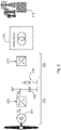
- FIG. 2 shows the power path of electrical power. It starts with the generator 201, which can be designed as a synchronous generator and which produces an alternating current, in particular a stator current, as the generator current I G .
- the generator current I G is rectified via the active rectifier 202 and applied to a DC voltage intermediate circuit 204 as the rectified current I DC .
- This also controls the generator current I G , in particular the stator current. This also allows a generator current I G to be controlled, which inputs power into the generator when electrical power is drawn from the electrical supply network.
- the DC voltage intermediate circuit 204 has an intermediate circuit capacitor 206, which can also be referred to as a smoothing capacitor.
- a chopper circuit 208 is connected to the DC voltage intermediate circuit 204, which can dissipate electrical power and thus electrical energy from the DC voltage intermediate circuit.
- a grid-side inverter 210 generates a feed current as alternating current from the DC voltage intermediate circuit 204 in order to thereby feed electrical power, namely active power, into the electrical supply grid 212 .
- a transformer 214 is also arranged between the inverter 210 and the electrical supply network 212 .
- the wind energy installation in particular the grid-side inverter 210, works in a voltage-forming manner, in particular in a grid-forming manner.
- the rectifier 202 together with the chopper circuit 208, regulates the DC voltage intermediate circuit, ie the intermediate circuit voltage.
- This control can be referred to as intermediate circuit control 216 .
- the rectifier 202 regulates the intermediate circuit voltage, which includes a lower current limit for the rectified current. If the lower current limit is reached, the The intermediate circuit voltage can no longer be maintained by the rectifier 202 and the chopper circuit 208 can then take over the control of the intermediate circuit voltage. Therefore, the rectifier 202 and the chopper circuit 208 jointly regulate the intermediate circuit voltage. This differs from a variant in which the rectifier alone regulates the intermediate circuit voltage without a lower current limit or with a much higher lower current limit.
- a dynamic current limit 218 is implemented in the inverter 210, which prevents jumps in the feed current that are too large, in order thereby to avoid large jumps in torque at the generator.
- FIG 3 shows two partial diagrams that explain at least part of the mode of operation of the proposed method.
- the upper diagram shows a time profile of a feed current I Net fed into the electrical supply network and an associated torque M Gen for an example situation.
- a lower current limit 302 is provided for this purpose, which is reached by the feed current and can be, for example, 10% of the rated current I N above the current feed current.
- the maximum current, power and torque surge in the positive direction is 10%.
- the dynamic current limitation therefore only allows a torque surge corresponding to the limit minus the current current.
- This current limiter 302 can therefore be displaced, which is indicated by the double arrow.
- the surge begins at time t 2 and ends at time t 3 , and in between there is a correction power P A , which is effective for the period in between that is indicated by a double arrow, even if its magnitude is limited. It can thus be regulated, but without overloading the wind turbine.
- the limitation can also take place via a static of the intermediate circuit control.
- the grid-side voltage-defining inverter would then limit the feed-in current when the intermediate circuit voltage collapses. It would thus recognize its current limitation via the intermediate circuit voltage.
- the lower partial diagram of figure 3 shows how the method can be implemented using appropriately set statics.
- Statics specify a relationship, especially a linear relationship, between an input variable and an output variable.
- a rectifier static 320 is used as a basis here, which specifies a relationship between the intermediate circuit voltage U ZK and the generator power P Gen . It is shown as solid lines.
- the rectifier droop is then shown at a level slightly above the coordinate axis, which marks a normal or medium value.
- the generator power P Gen is accordingly increased in accordance with the rectification droop 320 up to a maximum value.
- the generator power P Gen increases up to the maximum value according to the rectifier droop 320. This is adapted to the current limitation of the grid-side inverter.
- the chopper static 330 which is also drawn in and is shown as dashed lines, is not used in this example because the intermediate circuit voltage falls below its nominal value and therefore does not trigger the chopper circuit.
- the rectifier statics 320 and also the chopper statics 330 can be changed dynamically and they represent here a rectifier regulation or a chopper regulation. For this purpose, it is particularly proposed for the rectifier static 320 that its final values can be changed. This is indicated by the first and second change double arrows 322 and 324.
- the lower end value of the rectifier droop 320 forms a lower power limit 325, which can be implemented by a lower current limit, or vice versa.
- This lower power limit 325 can be changed dynamically, which is indicated by the change double arrow 324 .
- the edge of the rectifier static 320 extends to the intermediate circuit reference value 326 of the intermediate circuit voltage U ZK .
- the intermediate circuit reference value 326 also changes depending on the value to which the power limitation 325 is set. That's in the figure 3 recognizable by the fact that the chopper static 330 reaches the abscissa, ie the zero line, at the intermediate circuit reference value 326.
- a fixed triggering voltage 332' can be provided, which is fixed at a value above the intermediate circuit reference value 326 and also above a nominal voltage of the intermediate circuit voltage UZK.
- the rectifier thus leads the rectified current and thus ultimately the generator power to the drop in the intermediate circuit voltage only until the right horizontal branch of the rectifier static is reached, that is, until the power limit 325 is reached.
- the generator torque thus drops somewhat, but not completely.
- the operating point or an operating point lies on the chopper static 330 and falls further with it as the intermediate circuit voltage increases.
- the triggering voltage 332 is set to the intermediate circuit reference value 326 here.
- the chopper circuit dissipates power from the intermediate circuit.
- the generator torque could be limited, but a further drop in the power fed in did not have to be limited. This is illustrated by the representation of the feed-in current I Net .
- the generator torque M Gen and the feed current I Net are shown normalized to their nominal values in the upper part of the diagram, so that they would have to be approximately one above the other without the torque limitation described.
- the chopper static 330 can also be dynamically shifted to take care of further performance.
- the triggering voltage 332 track the intermediate circuit reference value 326, as a result of which a change in the power limit 325 is tracked, ie a change in the lower current limit.
- the chopper static 330 is adjusted accordingly by shifting its edge, which is indicated by the double arrow 338 .
- a shift in the lower power limit according to the change arrow 324 thus leads to a change in the chopper statics according to the double arrow 338.
- the start of the chopper static 330 which can also be referred to as the chopper characteristic curve, naturally only starts at the zero point, which lies on the abscissa of the intermediate circuit voltage.
- Two options are suggested for placing the chopper characteristic. Either the chopper characteristic is to the right of the overall statics of the intermediate circuit control, i.e. according to the Figures 3 and 4 to the right of the edge of the rectifier static 320, ie to the right of the intermediate circuit reference value 326. If the rectified current is limited, ie the generator power is limited, the intermediate circuit voltage must first reach a certain level before the chopper circuit becomes active. This is drawn in as an alternative possibility with the alternative triggering voltage 332'.
- the second possibility is a shift to the left.
- the start is then the intermediate circuit voltage, at which the limitation of the current begins, as at the intermediate circuit reference value 326, which is in the Figures 3 and 4 is marked as the main variant. Together with the dynamic limit of the power limitation 325, this results in continuous control.
- the chopper circuit which can simply be called the chopper, handles the additional power (here about 15%).
- Two operating points are formed at t 2 .
- the limits are approached to the current operating point via a PT1 characteristic.
- the deceleration characteristic results from the permissible mechanical load.
- the rectifier also takes over the power, which is converted in the chopper, with a delay.
- the proposed method thus avoids or improves the following situation: Without the proposed limitations, a line-side current surge, which can occur when there is a voltage change due to the voltage-defining feed, runs almost unhindered into the generator torque. The generator torque can therefore increase just as much. However, a chopper circuit would also not be active in the case of negative power gradients, because the voltage change in the intermediate circuit voltage resulting from the negative power gradients would be corrected by the active rectifier.
- the chopper circuit only takes over when the generator-side rectifier reaches its current limit. This means that current, power and torque jumps would not be limited and such jumps can be up to 100% of the nominal value.
- a solution has thus been created which enables network-forming properties to be provided with a wind energy installation without or without major oversizing of the mechanical system and without integrating an electrical storage device, ie which goes beyond a conventional intermediate circuit capacitor.
- the invention is based on the consideration that the mechanical system of a wind turbine, which can also be abbreviated to WTG, can withstand torque jumps of, for example, a maximum of 10%.
- WTG wind turbine
- network-forming properties at the system terminals require an intermediate circuit control on the generator side, which can lead to high transients in the torque. This acts like a direct coupling from the generator to the grid.
- the idea is to limit load surges by applying voltage in the positive and negative directions.
- the positive direction ie if the active power fed in or the associated active current I actual of the feed current I net is increased, this can be done in particular by limiting the output current to, for example , I actual +10% I N .
- the limit in the statics of the intermediate circuit control can also be adjusted dynamically.
- the limitation is preferably carried out by dynamically adapting a chopper static and limiting the static of the intermediate circuit control of the generator-side converter, which can also be used as a generator-side inverter or active rectifier can be called.
- Tracking after a load surge is carried out using a time delay, e.g. according to a PT1 behavior.
- the current can be limited directly in the grid-side voltage-defining inverter, or a severe drop in the intermediate circuit voltage can be reacted to with a current limitation.
- a collapse in the intermediate circuit voltage can result if the active rectifier, i.e. the rectifier on the generator side, limits the sudden change in torque.
- a wind turbine is typically constructed in such a way that the generator is decoupled from the grid.
- the DC link voltage is controlled by the line-side inverter.
- a wind energy plant with a network-forming converter or inverter can be constructed in such a way that the generator is decoupled from the network by intermediate circuit regulation, ie regulation of the intermediate circuit voltage, taking place using a battery storage device with a DC converter.
- the battery storage is coupled via the DC converter, which can therefore also be referred to as a DC/DC converter on the storage side.
- the battery storage can regulate the intermediate circuit voltage.
- a wind energy plant with a grid-forming converter or grid-forming inverter in which the generator is basically coupled to the grid, i.e. to the electrical supply grid, namely by intermediate circuit control by a generator-side inverter, which can also be used as a generator-side rectifier, or active rectifier.
- the generator be decoupled from the grid for the wind energy plant with a grid-forming converter or inverter.
- a grid-forming converter or inverter For this purpose, an intermediate circuit control by means of a chopper circuit, which can also simply be referred to as a synonym as a chopper, is proposed, with an active rectifier on the generator side.
- Torque limitation is implemented by a dynamic mains-side current limit.
Landscapes
- Engineering & Computer Science (AREA)
- Power Engineering (AREA)
- Physics & Mathematics (AREA)
- General Physics & Mathematics (AREA)
- Control Of Eletrric Generators (AREA)
- Supply And Distribution Of Alternating Current (AREA)
Description
Die vorliegende Erfindung betrifft ein Verfahren zum Einspeisen elektrischer Leistung in ein elektrisches Versorgungsnetz mittels einer Windenergieanlage. Außerdem betrifft die vorliegende Erfindung eine entsprechende Windenergieanlage.The present invention relates to a method for feeding electrical power into an electrical supply network using a wind power plant. In addition, the present invention relates to a corresponding wind energy installation.
Windenergieanlagen sind bekannt. Sie speisen elektrische Leistung in ein elektrisches Versorgungsnetz ein. Üblicherweise speisen Windenergieanlagen stromprägend in ein elektrisches Versorgungsnetz ein. Das bedeutet besonders, dass ebenfalls mit dem elektrischen Versorgungsnetz gekoppelte Großkraftwerke, die in das elektrische Versorgungsnetz mittels direkt gekoppelter Synchrongeneratoren einspeisen, die Netzspannung des elektrischen Versorgungsnetzes vorgeben. Dabei geben sie auch Frequenz und Phase des elektrischen Versorgungsnetzes vor, nämlich Frequenz und Phase der Netzspannung. Solche Großkraftwerke geben somit die Spannung vor und arbeiten damit spannungsprägend. Das erfolgt besonders auch durch die physikalischen Eigenschaften der Synchrongeneratoren.Wind turbines are known. They feed electrical power into an electrical supply network. Usually, wind turbines feed current into an electrical supply network. This means in particular that large power plants that are also coupled to the electrical supply network and feed into the electrical supply network by means of directly coupled synchronous generators specify the mains voltage of the electrical supply network. They also specify the frequency and phase of the electrical supply network, namely the frequency and phase of the mains voltage. Such large-scale power plants thus specify the voltage and thus work in a voltage-defining manner. This is especially due to the physical properties of the synchronous generators.
Ein gattungsgemäßes Verfahren ist beispielsweise aus dem Dokument
Bei einer spannungsprägenden Einspeisung steht die Vorgabe der einzuspeisenden bzw. im elektrischen Versorgungsnetz bereitzustellenden Spannung im Vordergrund. Die Windenergieanlage versucht also mit einer vorgegebenen Spannungshöhe einzuspeisen und diese Spannungshöhe im elektrischen Versorgungsnetz möglichst zu halten und damit besonders vorzugehen. Hierbei ergibt sich auch ein Einspeisestrom, der aber eher Mittel zum Zweck ist.In the case of a voltage-defining feed, the specification of the voltage to be fed in or to be provided in the electrical supply network is paramount. The wind energy installation tries to feed in with a predetermined voltage level and to keep this voltage level in the electrical supply network as possible and thus to proceed in a special way. This also results in a feed-in current, but this is more of a means to an end.
Eine spannungsprägende Einspeisung und eine stromprägende Einspeisung sind jeweils Fachbegriffe mit der vorstehend erläuterten Bedeutung.A voltage-defining feed and a current-defining feed are each technical terms with the meaning explained above.
Bisher war es nicht üblich, mit Windenergieanlagen spannungsprägend einzuspeisen, weil eine solche spannungsprägende Einspeisung in ein spannungsgeführtes elektrisches Versorgungsnetz bei Spannungsschwankungen im elektrischen Versorgungsnetz mit hohen Schwankungen der Wirkleistung einhergehen kann. Solche Leistungsschwankungen sind bei Windenergieanlagen unerwünscht und aufgrund des Windes als primärer Energiequelle auch nur begrenzt verfügbar.Up until now, it has not been customary to feed in voltage-defining power with wind turbines, because such a voltage-defining feed into a voltage-controlled electrical supply network can be associated with high fluctuations in the active power in the event of voltage fluctuations in the electrical supply network. Such power fluctuations are undesirable in wind turbines and are also only available to a limited extent due to the wind as the primary energy source.
Dennoch nehmen Windenergieanlagen in manchen Ländern bzw. in manchen elektrischen Versorgungsnetzen eine zunehmend wichtige Rolle ein und liefern zunehmend einen größeren Anteil der eingespeisten Leistung des elektrischen Versorgungsnetzes. Daher kann es wünschenswert sein, dass Windenergieanlagen auch spannungsprägend einspeisen oder gegebenenfalls sogar die einzigen Einspeiser sind, die spannungsprägend einspeisen. Das kommt besonders dann in Betracht, wenn in einem elektrischen Versorgungsnetz bzw. einem relevanten Netzabschnitt keine herkömmlichen Großkraftwerke mehr einspeisen, sei es dauerhaft oder temporär.Nevertheless, wind turbines are playing an increasingly important role in some countries or in some electrical supply networks and are increasingly supplying a larger proportion of the power fed into the electrical supply network. It can therefore be desirable for wind turbines to also feed in voltage-defining power or possibly even be the only feeders that feed in voltage-defining power. This is particularly important when conventional large power plants are no longer feeding into an electrical supply network or a relevant network section, be it permanently or temporarily.
Ein weiteres Problem, das bei einer spannungsprägenden Einspeisung mittels Windenergieanlagen auftreten kann, ist, dass plötzliche Spannungsschwankungen der Netzspannung zu entsprechend starken und besonders auch zu entsprechend schnellen Änderungen der eingespeisten Wirkleistung der Windenergieanlage führen können. Solche schnellen Leistungsänderungen können zu ähnlich schnellen Änderungen des Drehmomentes des Generators der Windenergieanlage führen. Besonders annähernd sprungförmige Änderungen der eingespeisten Leistung können zu entsprechend sprungförmigen Änderungen oder nahezu sprungförmigen Änderungen des Drehmomentes der Windenergieanlage führen, also des Drehmomentes des Generators. Je nach Höhe eines solchen Drehmomentsprungs oder überhaupt einer schnellen Drehmomentänderung kann dies zu einer mechanischen Belastung oder sogar mechanischen Gefährdung der Windenergieanlage führen.A further problem that can occur when the voltage is fed in by means of wind energy installations is that sudden voltage fluctuations in the mains voltage can lead to correspondingly strong and, in particular, also correspondingly rapid changes in the active power fed in by the wind energy installation. Such Rapid power changes can lead to similarly rapid changes in the torque of the generator of the wind turbine. In particular, almost abrupt changes in the power fed in can lead to corresponding abrupt changes or almost abrupt changes in the torque of the wind turbine, ie the torque of the generator. Depending on the level of such a torque jump or even a rapid change in torque, this can lead to mechanical stress or even a mechanical hazard to the wind energy installation.
Der vorliegenden Erfindung liegt somit die Aufgabe zugrunde, zumindest eines der vorstehend genannten Probleme zu adressieren. Insbesondere soll eine Lösung geschaffen werden, bei der eine Windenergieanlage spannungsprägend in das elektrische Versorgungsnetz einspeisen kann, ohne die Windenergieanlage einer mechanischen Überlastung auszusetzen. Zumindest soll zu bisher bekannten Lösungen eine alternative Lösung vorgeschlagen werden.The present invention is therefore based on the object of addressing at least one of the problems mentioned above. In particular, a solution is to be created in which a wind energy installation can feed voltage into the electrical supply network without subjecting the wind energy installation to mechanical overload. At the very least, an alternative solution to previously known solutions should be proposed.
Erfindungsgemäß wird ein Verfahren nach Anspruch 1 vorgeschlagen. Das Verfahren betrifft somit das Einspeisen elektrischer Leistung in ein eine Netzspannung aufweisendes elektrisches Versorgungsnetz mittels einer Windenergieanlage. Dafür wird eine Windenergieanlage zugrunde gelegt, die einen Generator, einen aktiven Gleichrichter, einen Gleichspannungszwischenkreis mit einem Chopperkreis und einen Wechselrichter aufweist. Mit dem Generator wird ein Generatorstrom erzeugt, nämlich üblicherweise ein Statorstrom. Insoweit wird insbesondere vorgeschlagen, als Generator einen Synchrongenerator zu verwenden. Dieser kann fremderregt sein oder Permanentmagnete aufweisen.According to the invention a method according to
Dieser erzeugte Generatorstrom, also insbesondere Statorstrom, wird mit einem aktiven Gleichrichter in einen Gleichstrom gleichgerichtet, der hier als Gleichrichtstrom bezeichnet wird, und in den Gleichspannungszwischenkreis eingegeben, dort also eingespeist. Der Gleichspannungszwischenkreis nimmt diesen Gleichrichtstrom bzw. die Energie, die dieser mitführt, auf. Der aktive Gleichrichter kann auch als generatorseitiger Wechselrichter bezeichnet werden, denn er stellt einen Zusammenhang zwischen dem Gleichrichtstrom und dem erzeugen Generatorstrom her, wobei lediglich üblicherweise der Energiefluss vom Generator zum Gleichspannungszwischenkreis verläuft. Das kann in Ausnahmesituationen aber auch anders sein. Um Verwechslungen mit dem netzseitigen Wechselrichter zu vermeiden, wird hier von einem aktiven Gleichrichter gesprochen.This generated generator current, that is to say in particular the stator current, is rectified using an active rectifier into a direct current, which is referred to here as a rectified current, and input into the DC voltage intermediate circuit, ie fed in there. The DC voltage intermediate circuit absorbs this rectified current or the energy that it carries. The active rectifier can also be referred to as a generator-side inverter, because it establishes a connection between the rectified current and the generated generator current, with the energy flow usually only running from the generator to the DC voltage intermediate circuit. However, this can also be different in exceptional situations. In order to avoid confusion with the grid-side inverter, this is referred to as an active rectifier.
Dieser aktive Gleichrichter richtet den erzeugten Generatorstrom somit gezielt gleich und kann dabei auch die Zwischenkreisspannung des Gleichspannungszwischenkreises steuern bzw. ausregeln. Außerdem kann mit dem aktiven Gleichrichter auch der erzeugte Generatorstrom, also insbesondere der Statorstrom des Generators, gesteuert werden. Mit dem aktiven Gleichrichter ist somit auch das Drehmoment des Generators steuerbar, zumindest beeinflussbar. Ist der Generator als permanent erregter Synchrongenerator ausgebildet, so erfolgt im Grunde die Steuerung des elektrischen Drehmomentes des Generators über den Statorstrom und damit durch den aktiven Gleichrichter.This active rectifier thus rectifies the generated generator current in a targeted manner and can also control or regulate the intermediate circuit voltage of the DC voltage intermediate circuit. In addition, the generated generator current, ie in particular the stator current of the generator, can also be controlled with the active rectifier. The torque of the generator can thus also be controlled, at least influenced, with the active rectifier. If the generator is designed as a permanently excited synchronous generator, the electric torque of the generator is basically controlled via the stator current and thus by the active rectifier.
Mit dem Gleichspannungszwischenkreis ist ein Wechselrichter verbunden, um einen Einspeisestrom zum Einspeisen in das elektrische Versorgungsnetz zu erzeugen. Somit bildet dieser Wechselrichter einen netzseitigen Wechselrichter, weil er mit dem elektrischen Versorgungsnetz verbunden ist, wobei weitere Elemente, wie z.B. ein Transformator, zwischengeschaltet sein können. Soweit nachfolgend von einem Wechselrichter die Rede ist, ist grundsätzlich dieser netzseitige Wechselrichter gemeint, wohingegen der genannte generatorseitige Wechselrichter als aktiver Gleichrichter bezeichnet wird.An inverter is connected to the intermediate DC circuit in order to generate a feed current for feeding into the electrical supply network. This inverter thus forms a grid-side inverter because it is connected to the electrical supply grid, with other elements such as a transformer being able to be interposed. Insofar as an inverter is discussed below, this line-side inverter is generally meant, whereas the named generator-side inverter is referred to as an active rectifier.
Es wird dann vorgeschlagen, dass das Einspeisen spannungsprägend erfolgt. Der Wechselrichter wirkt also einer Abweichung der Netzspannung von einem Spannungssollwert durch eine Anpassung des eingespeisten Stroms entgegen. Dazu kann eine Ausgangsspannung an Ausgangsklemmen des Wechselrichters vorgegeben werden und die spannungsprägende Einspeisung regelt diese Spannung an den Ausgangsklemmen aus, und daraus ergibt sich eine Höhe des Stroms, also das Einspeisestroms. Es ergibt sich somit ein Strom aufgrund der direkt geregelten Ausgangsspannung, das kann auch so bezeichnet werden, dass die Spannung an den Klemmen festgehalten wird. Besonders erfolgt ein Ausregeln der Spannung mit stationärer Genauigkeit. Das Ausregeln der Spannung ist das vorrangige Regelungsziel. Eine spannungsprägende Einspeisung bezeichnet besonders eine Einspeisung, bei der der Einspeiser, hier also die Windenergieanlage, die eingespeiste Spannung auch der Höhe nach führt.It is then suggested that the feeding-in takes place in a voltage-forming manner. The inverter therefore counteracts a deviation in the mains voltage from a desired voltage value by adapting the current fed in. For this purpose, an output voltage can be specified at the output terminals of the inverter and the voltage-defining feed regulates this voltage at the output terminals, and this results in a current level, ie the feed current. This results in a current due to the directly regulated output voltage, which can also be described as the voltage at the terminals being fixed. In particular, the voltage is adjusted with steady-state accuracy. Correcting the voltage is the primary control objective. A voltage-defining feed-in refers in particular to a feed-in in which the feeder, in this case the wind turbine, also carries the fed-in voltage in terms of height.
Dazu wird nun vorgeschlagen, dass der aktive Gleichrichter eine untere Strombegrenzung aufweist, die auch einfach als Strombegrenzung oder Gleichstrombegrenzung bezeichnet werden kann, um bei einer Änderung der Netzspannung in Amplitude und/oder Phasenlage einen Abfall des Gleichrichtstroms zum Schutz des Generators zu begrenzen. Zur Umsetzung kann die Höhe des Gleichrichtstromes oder auch des gleichzurichtenden Generatorstroms, insbesondere Statorstromes, überwacht werden. Hier wurde besonders erkannt, dass ein Spannungsanstieg der Netzspannung oder eine Winkeländerung der Netzspannung, besonders hin zum Spannungswinkel an den Ausgangsklemmen der Windenergieanlage, zu einer Reduzierung der eingespeisten Wirkleistung führt. Das wirkt sich auf den Gleichspannungszwischenkreis aus und das wiederum kann dazu führen, dass der Gleichrichtstrom reduziert wird. Eine zu starke Reduzierung des Gleichrichtstroms kann durch die untere Strombegrenzung vermieden werden, wodurch mechanische Überlastungen durch eine zu schnelle Drehmomentveränderung des Generators vermieden wird. Die untere Strombegrenzung begrenzt somit auch eine Generatorleistung und auch einen Generatorstrom, insbesondere Statorstrom. Gleichwirkend kann auch die Generatorleistung, der Generatorstrom oder der Statorstrom durch eine untere Grenze begrenzt werden. Das entspricht sinngemäß der Begrenzung des Gleichrichtstromes durch die untere Strombegrenzung, denn der Gleichrichtstrom wird dadurch auch begrenzt.To this end, it is now proposed that the active rectifier have a lower current limitation, which can also simply be referred to as current limitation or direct current limitation, in order to limit a drop in the rectified current to protect the generator when the mains voltage changes in amplitude and/or phase position. For implementation, the level of the rectified current or the generator current to be rectified, in particular the stator current, can be monitored. Here it was particularly recognized that a voltage increase in the mains voltage or a Change in the angle of the grid voltage, especially towards the voltage angle at the output terminals of the wind turbine, leads to a reduction in the active power fed in. This has an effect on the DC voltage intermediate circuit and this in turn can lead to the rectified current being reduced. An excessive reduction in the rectified current can be avoided by the lower current limitation, which avoids mechanical overloads caused by a too rapid torque change of the generator. The lower current limitation thus also limits a generator output and also a generator current, in particular a stator current. With the same effect, the generator power, the generator current or the stator current can also be limited by a lower limit. This corresponds to the limitation of the rectified current by the lower current limitation, because the rectified current is also limited by this.
Dabei wird vorgeschlagen, dass die untere Strombegrenzung in Abhängigkeit von einem Betriebspunkt der Windenergieanlage eingestellt und verändert wird. Insbesondere erfolgt dies in Abhängigkeit von einem Betriebspunkt des aktiven Gleichrichters.In this case, it is proposed that the lower current limit is set and changed as a function of an operating point of the wind energy installation. In particular, this takes place as a function of an operating point of the active rectifier.
Ein anschauliches Beispiel, das aber auch eine relevante Ausführungsform beschreibt, besteht darin, die untere Strombegrenzung zunächst so einzustellen, dass sie um 5 bis 15%, insbesondere 10 %, bezogen auf einen maximalen Gleichrichtstrom oder einen Nenngleichrichtstrom, unterhalb des aktuellen Gleichrichtstroms liegt, zumindest zu Beginn einer Änderung des Gleichrichtstromes dieser Höhe.An illustrative example, which also describes a relevant embodiment, is to first set the lower current limit so that it is 5 to 15%, in particular 10%, based on a maximum rectified current or a nominal rectified current, below the current rectified current, at least at the beginning of a change in the direct current of this magnitude.
Durch die untere Strombegrenzung soll eine zu starke Änderung des Drehmomentes des Generators vermieden werden. Daher wird vorgeschlagen, die untere Strombegrenzung mit der Zeit aber weiter zu verändern, besonders, wenn der Gleichrichtstrom die untere Strombegrenzung erreicht hat, also insbesondere auf den aktuellen Wert der unteren Strombegrenzung abgefallen ist. Diese untere Strombegrenzung des aktiven Gleichrichters wird hier als Gleichrichtstrombegrenzung bezeichnet. Ist sie erreicht, kann sie aber weiter verändert werden, insbesondere weiter abgesenkt werden, um bei Bedarf eine weitere Verringerung des Gleichrichtstroms zu erlauben. Wichtig ist nur, dass der Gleichrichtstrom keine zu starken Änderungen in einer vorbestimmten Zeit aufweist.The lower current limitation is intended to avoid an excessive change in the generator torque. It is therefore proposed to change the lower current limit further over time, particularly when the rectified current has reached the lower current limit, that is to say has dropped in particular to the current value of the lower current limit. This lower current limit of the active rectifier is referred to here as the rectified current limit. Once it has been reached, however, it can be changed further, in particular lowered further, in order to allow a further reduction in the rectified current if required. It is only important that the rectified current does not change too much in a predetermined time.
Äquivalent kann auch der Generatorstrom, insbesondere der Statorstrom, begrenzt werden, was dieselbe Wirkung haben kann wie den Gleichrichtstrom zu begrenzen, jedenfalls dann, wenn sich die Begrenzung des Generatorstroms, der ein Wechselstrom ist, auf den Wirkanteil des erzeugten Generatorstroms bezieht. Insoweit ist die Umsetzung einfacher, den Gleichrichtstrom zu begrenzen; den erzeugten Generatorstrom in der genannten Art und Weise zu begrenzen führt aber dem Grunde nach zum selben Ergebnis.Equivalently, the generator current, in particular the stator current, can also be limited, which can have the same effect as limiting the rectified current, at least when the limitation of the generator current, which is an alternating current, relates to the active component of the generated generator current. So far the implementation easier to limit the direct current; Limiting the generated generator current in the manner mentioned basically leads to the same result.
Außerdem wird vorgeschlagen, dass der Chopperkreis so gesteuert wird, dass er überschüssige Energie, die durch die untere Strombegrenzung des aktiven Gleichrichters in dem Gleichspannungszwischenkreis auftritt, oder ein Teil davon, aus dem Gleichspannungszwischenkreis abführt. Hier wurde besonders erkannt, dass die untere Strombegrenzung des aktiven Gleichrichters, also die Gleichrichtstrombegrenzung, dazu führen kann, dass überschüssige Energie in dem Gleichspannungszwischenkreis auftritt. Dieses Auftreten der überschüssigen Energie kann besonders bedeuten, dass der Generator mehr Energie bzw. mehr Leistung in den Gleichspannungszwischenkreis einspeist als in das elektrische Versorgungsnetz eingespeist wird. Diese Energie kann durch den Chopperkreis abgeführt werden.In addition, it is proposed that the chopper circuit be controlled in such a way that it dissipates excess energy, which occurs in the DC voltage intermediate circuit due to the lower current limitation of the active rectifier, or part thereof, from the DC voltage intermediate circuit. Here it was recognized in particular that the lower current limitation of the active rectifier, that is to say the rectification current limitation, can lead to excess energy occurring in the intermediate DC voltage circuit. This occurrence of the excess energy can mean in particular that the generator feeds more energy or more power into the DC voltage intermediate circuit than is fed into the electrical supply network. This energy can be dissipated by the chopper circuit.
Der Chopperkreis arbeitet dabei besonders so, dass er durch ein gepulstes Verfahren von dem Gleichspannungszwischenkreis einen gepulsten Strom durch entsprechende Schaltung von einem oder mehreren Halbleiterschaltern durch einen Chopperwiderstand erzeugt. Die abgeführte Energie wird in dem Chopperwiderstand dabei in Wärme umgewandelt.In this case, the chopper circuit works in particular in such a way that it generates a pulsed current from the DC voltage intermediate circuit by means of a pulsed process by appropriate switching of one or more semiconductor switches through a chopper resistor. The dissipated energy is converted into heat in the chopper resistor.
Besonders kann hierdurch erreicht werden, dass auch sehr starke Stromänderungen des eingespeisten Wirkstroms möglich sind, um einer ansteigenden Netzspannung, einer Veränderung des Netzphasenwinkels oder eine Beschleunigung der Netzfrequenz entgegenzuwirken. Dabei kann eine mechanische Überlastung der Windenergieanlage, besonders eine zu starke und zu schnelle Veränderung des Generatormoments, vermieden werden. Gleichzeitig ist nur ein geringer apparativer Aufwand, möglicherweise kein zusätzlicher apparativer Aufwand, nötig, um diese spannungsprägende Einspeisung zu realisieren. Insbesondere kann ein zusätzlicher Energiespeicher, wie Batteriebänke, oder andere elektrische Energiespeicher, die über einen Zwischenkreiskondensator hinausgehen, vermieden werden.In particular, it can be achieved in this way that very strong current changes of the active current fed in are also possible in order to counteract an increasing mains voltage, a change in the mains phase angle or an acceleration of the mains frequency. In this way, mechanical overloading of the wind energy installation, in particular excessively rapid changes in the generator torque, can be avoided. At the same time, only a small outlay on equipment, possibly no additional outlay on equipment, is necessary in order to implement this voltage-defining feed. In particular, an additional energy store, such as battery banks, or other electrical energy stores that go beyond an intermediate circuit capacitor, can be avoided.
Gemäß einer Ausführungsform wird vorgeschlagen, dass der Chopperkreis Energie aus dem Gleichspannungszwischenkreis abführt, sobald die Zwischenkreisspannung eine Auslösespannung erreicht hat. Der Chopperkreis kann damit auf einfache Art und Weise realisiert werden, indem er die Zwischenkreisspannung überwacht. Wird sie zu groß, beginnt der Chopperkreis, Energie abzuführen, was auch als Choppern bezeichnet werden kann.According to one embodiment, it is proposed that the chopper circuit dissipate energy from the DC voltage intermediate circuit as soon as the intermediate circuit voltage has reached a triggering voltage. The chopper circuit can thus be implemented in a simple manner by monitoring the intermediate circuit voltage. Does she get too big the chopper circuit begins to dissipate energy, which can also be referred to as chopping.
Dies wirkt zusammen mit einem aktiven Gleichrichter, der durch das Steuern des Gleichrichtstroms die Zwischenkreisspannung regelt, um die Zwischenkreisspannung auf einen Wert oder einen Bereich unterhalb der Auslösespannung zu regeln. Im Normalfall regelt der aktive Gleichrichter also die Zwischenkreisspannung auf einen gewünschten Wert oder zumindest gewünschten Spannungsbereich ein. Die Auslösespannung wird dabei nicht erreicht und der Chopperkreis bleibt somit inaktiv.This works in conjunction with an active rectifier that regulates the intermediate circuit voltage by controlling the rectified current to regulate the intermediate circuit voltage to a value or range below the trigger voltage. In the normal case, the active rectifier regulates the intermediate circuit voltage to a desired value or at least a desired voltage range. The triggering voltage is not reached and the chopper circuit remains inactive.
Es wird aber weiter vorgeschlagen, dass das Verfahren so funktioniert, dass dann, wenn der Gleichrichtstrom die Gleichrichtstrombegrenzung erreicht hat und dadurch beschränkt wird, die Zwischenkreisspannung weiter ansteigt. Diese steigt daraufhin an, bis sie die Auslösespannung erreicht hat. Das führt schließlich dazu, dass der Chopperkreis anspricht und Energie aus dem Gleichspannungszwischenkreis abführt.However, it is further proposed that the method functions in such a way that when the rectified current has reached the rectified current limitation and is thereby restricted, the intermediate circuit voltage continues to rise. This then increases until it reaches the trigger voltage. This finally leads to the chopper circuit responding and dissipating energy from the DC link.
Es wurde erkannt, dass ein Chopperkreis grundsätzlich dazu ausgelegt ist, Energie aus einem Gleichspannungszwischenkreis abzuführen. Erreicht der Gleichspannungszwischenkreis die Auslösespannung, setzt dieses Abführen der Energie ein und wirkt dabei auch einem weiteren Anstieg der Zwischenkreisspannung in dem Gleichspannungszwischenkreis entgegen.It has been recognized that a chopper circuit is fundamentally designed to dissipate energy from a direct voltage intermediate circuit. If the intermediate DC circuit reaches the triggering voltage, this dissipation of the energy begins and also counteracts a further rise in the intermediate circuit voltage in the intermediate DC circuit.
Durch den bevorzugten aktiven Gleichrichter, der die Zwischenkreisspannung regelt, kann die Zwischenkreisspannung im Grunde ohne Energieverlust auf dem gewünschten Spannungswert oder in dem gewünschten Spannungsbereich, also Spannungsband, gehalten werden. Dies ist eine gute Basis für den netzseitigen Wechselrichter, davon elektrische Leistung in das elektrische Versorgungsnetz einzuspeisen.The preferred active rectifier, which regulates the intermediate circuit voltage, means that the intermediate circuit voltage can basically be kept at the desired voltage value or in the desired voltage range, ie the voltage range, without any loss of energy. This is a good basis for the grid-side inverter to feed electrical power into the electrical supply grid.
Es wurde aber erkannt, dass dieser ansonsten vorteilhafte aktive Gleichrichter im Falle der spannungsprägenden Einspeisung zu einer mechanischen Belastung des Generators führen kann. Durch die spannungsprägende Einspeisung kann es bei entsprechenden Spannungsänderungen der Netzspannung zu entsprechend schnellen und starken Änderungen der eingespeisten Wirkleistung kommen. Dies macht sich im Gleichspannungszwischenkreis bemerkbar und der aktive Gleichrichter versucht dies auszuregeln. Verringert sich also die eingespeiste Wirkleistung, verringert sich der Einspeisestrom bzw. der Wirkanteil des Einspeisestroms. Durch das Ausregeln der Zwischenkreisspannung verringert sich somit auch durch den aktiven Gleichrichter der Gleichrichtstrom und damit auch der Generatorstrom bzw. Statorstrom. Das führt zu einer entsprechenden Verringerung des Generatormomentes. Erfolgen diese Vorgänge schnell, also insbesondere sprunghaft, so stellt sich auch eine entsprechend schnelle bzw. sprunghafte Änderung des Generatormomentes ein.However, it was recognized that this active rectifier, which is otherwise advantageous, can lead to a mechanical load on the generator in the case of the voltage-defining feed. Due to the voltage-defining infeed, corresponding voltage changes in the mains voltage can lead to correspondingly rapid and strong changes in the active power fed in. This is noticeable in the intermediate DC circuit and the active rectifier attempts to correct this. So if the active power fed in is reduced, the feed-in current or the active component of the feed-in current is reduced. As a result of the DC link voltage being corrected, the rectified current is also reduced by the active rectifier, and with it also the generator current or stator current. This leads to a corresponding reduction in the generator torque. If these processes take place quickly, that is to say in particular abruptly, then there is also a correspondingly rapid or abrupt change in the generator torque.
Der Chopperkreis kann dies nicht verhindern und bleibt inaktiv, weil der aktive Gleichrichter die Zwischenkreisspannung ausregelt und damit die Auslösespannung nicht erreicht wird.The chopper circuit cannot prevent this and remains inactive because the active rectifier regulates the intermediate circuit voltage and the trigger voltage is therefore not reached.
Dieses Problem wurde erkannt und daher wird vorgeschlagen, dass der Gleichrichtstrom begrenzt wird, nämlich durch eine untere Gleichrichtstrombegrenzung. Der Gleichrichtstrom und damit der erzeugte Generatorstrom bzw. Statorstrom kann durch die untere Gleichrichtstrombegrenzung nicht so stark abfallen wie sich ansonsten aufgrund der Änderung der eingespeisten Wirkleistung ergeben würde. Der Generator erzeugt also mehr Leistung und damit mehr Energie als aufgrund der eingespeisten Wirkleistungsverringerung in das elektrische Versorgungsnetz eingespeist wird. Die Energie im Gleichspannungszwischenkreis steigt an und damit die Zwischenkreisspannung, bis diese die Auslösespannung erreicht hat. Die vorgeschlagene Gleichrichtstrombegrenzung führt somit zu dieser Erhöhung der Zwischenkreisspannung und damit zum Auslösen des Chopperkreises. Dadurch ergibt sich ein Zusammenspiel zwischen dem aktiven Gleichrichter und dem Chopperkreis. Dieses Zusammenspiel ist so, dass der aktive Gleichrichter eine zu starke Änderung des Generatormomentes verhindert, während der Chopperkreis die dabei auftretende überschüssige Energie abführt.This problem has been recognized and it is therefore proposed that the direct current is limited, namely by a lower direct current limit. The rectified current and thus the generated generator current or stator current cannot drop as sharply as would otherwise result from the change in the active power fed in due to the lower rectified current limitation. The generator therefore generates more power and thus more energy than is fed into the electrical supply network due to the fed-in active power reduction. The energy in the intermediate DC circuit rises, and with it the intermediate circuit voltage, until it has reached the tripping voltage. The proposed direct current limitation thus leads to this increase in the intermediate circuit voltage and thus to the tripping of the chopper circuit. This results in an interaction between the active rectifier and the chopper circuit. This interaction is such that the active rectifier prevents the generator torque from changing too much, while the chopper circuit dissipates the excess energy that occurs.
Gemäß einer Ausführungsform wird vorgeschlagen, dass der Chopperkreis eine Chopperstatik aufweist, die einen Zusammenhang zwischen einem die Auslösespannung überschreitenden Spannungswert der Zwischenkreisspannung und eine aus dem Gleichspannungszwischenkreis abzuführenden Leistung angibt, die hier als Chopperleistung bezeichnet wird. Insbesondere kann die Chopperstatik diesen Zusammenhang als linearen Zusammenhang aufweisen. Je stärker die Auslösespannung also von der Zwischenkreisspannung überschritten wird, umso mehr Leistung wird durch den Chopperkreis abgeführt.According to one embodiment, it is proposed that the chopper circuit has chopper statics that indicate a relationship between a voltage value of the intermediate circuit voltage that exceeds the triggering voltage and a power to be dissipated from the DC voltage intermediate circuit, which is referred to here as chopper power. In particular, the chopper statics can have this relationship as a linear relationship. The more the tripping voltage is exceeded by the intermediate circuit voltage, the more power is dissipated by the chopper circuit.
Dadurch kann erreicht werden, dass die Zwischenkreisspannung die Auslösespannung überschreiten kann und noch weiter ansteigen kann. Wie weit die Zwischenkreisspannung dann oberhalb der Auslösespannung liegt, lässt einen Rückschluss darauf zu, wie viel Leistung der Chopperkreis in diesem Moment abführt. Dann kann beispielsweise der netzseitige Wechselrichter abhängig von der Zwischenkreisspannung, insbesondere abhängig von dem Spannungswert, um den die Zwischenkreisspannung die Auslösespannung überschreitet, die eingespeiste Wirkleistung steuern, bzw. die Ausgansspannung in Amplitude, Phasenlage und Frequenz so anpassen, dass sich die Wirkleistung entsprechend anpasst.It can thereby be achieved that the intermediate circuit voltage can exceed the tripping voltage and can increase even further. The extent to which the intermediate circuit voltage is then above the triggering voltage allows a conclusion to be drawn as to how much power the chopper circuit is dissipating at that moment. Then, for example, the grid-side inverters depending on the intermediate circuit voltage, in particular depending on the voltage value by which the intermediate circuit voltage exceeds the triggering voltage, control the active power fed in, or adapt the output voltage in terms of amplitude, phase position and frequency so that the active power adapts accordingly.
Beispielsweise kommt in Betracht, dass eine sprunghafte Erhöhung der Netzspannung oder sprunghaft Veränderung der Netzphase zu einer sprunghaften Verringerung der eingespeisten Wirkleistung führt, was wiederum zu einer Begrenzung des Gleichrichtstroms nach unten geführt haben kann, mit der Folge, dass die Zwischenkreisspannung ansteigt und der Chopperkreis auslöst. Ändert sich nun die Netzspannung sprunghaft wieder zurück, so würde dies zu einer sprunghaften Erhöhung der eingespeisten Wirkleistung führen. Das kann ebenfalls zu einer Belastung des Generators führen, wenn diese sprunghafte Leistungserhöhung sich entsprechend bis zum Generator hin, also bis zu seinem Drehmoment hin, auswirkt. In diesem Fall könnte diese Leistungserhöhung der eingespeisten Wirkleistung begrenzt sein. Ist aber erkennbar, dass der Chopperkreis eine hohe Leistung abführt, so kann die genannte Begrenzung der Erhöhung der eingespeisten Wirkleistung entbehrlich sein oder kleiner ausfallen. Wenigstens könnte die eingespeiste Wirkleistung ohne Weiteres um den Betrag erhöht werden, um den der Chopperkreis Wirkleistung aus dem Gleichspannungszwischenkreis abführt.For example, it is possible that a sudden increase in the mains voltage or a sudden change in the mains phase leads to a sudden reduction in the active power fed in, which in turn may have led to a downward limitation of the rectified current, with the result that the intermediate circuit voltage increases and the chopper circuit trips . If the mains voltage suddenly changes back again, this would lead to a sudden increase in the active power fed in. This can also lead to a load on the generator if this abrupt increase in power has an effect right up to the generator, ie up to its torque. In this case, this power increase of the active power fed in could be limited. However, if it can be seen that the chopper circuit is dissipating a high level of power, then the stated limitation of the increase in the active power fed in may be unnecessary or may be smaller. At least the active power fed in could easily be increased by the amount by which the chopper circuit draws active power out of the intermediate DC voltage circuit.
In der Umsetzung kann dies lediglich bedeuten, dass der netzseitige Wechselrichter seine eingespeiste Wirkleistung umso stärker erhöhen darf, insbesondere umso stärker sprunghaft erhöhen darf, je höher die Zwischenkreisspannung ist.In practice, this can only mean that the grid-side inverter may increase its fed-in active power the more, in particular the more abruptly, the higher the intermediate circuit voltage.
Gemäß einer Ausführungsform wird vorgeschlagen, dass
- zum Regeln der Zwischenkreisspannung eine Regelungsvorschrift, insbesondre eine Regelungsstatik, vorgesehen ist, und die Regelungsvorschrift sich zusammensetzt aus
- einer Gleichrichterregelung, insbesondere einer Gleichrichterstatik, und einer Chopperregelung, insbesondere einer bzw. der Chopperstatik, wobei
- die Gleichrichterregelung einen Zusammenhang vorgibt zwischen der Zwischenkreisspannung und dem durch den aktiven Gleichrichter einzustellenden Gleichrichtstrom, derart, dass
- der einzustellende Gleichrichtstrom mit ansteigender Zwischenkreisspannung abfällt, insbesondere linear abfällt, bis der Gleichrichtstrom die untere Strombegrenzung erreicht hat, und
- der einzustellende Gleichrichtstrom bei weiter steigender Zwischenkreisspannung auf dieser unteren Strombegrenzung gehalten wird, und
- die Chopperregelung einen Zusammenhang vorgibt zwischen der Zwischenkreisspannung und einer bzw. der durch den Chopperkreis aus dem Zwischenkreis abzuführenden Chopperleistung, derart, dass
- die Chopperleistung mit zunehmender Zwischenkreisspannung zunimmt, sobald die Zwischenkreisspannung eine bzw. die Auslösespannung überschreitet, wobei
- die untere Strombegrenzung und/oder die Auslösespannung veränderbar sind und insbesondere in Abhängigkeit eines Arbeitspunktes der Windenergieanlage verändert werden.
- a control rule, in particular a control droop, is provided for controlling the intermediate circuit voltage, and the control rule is composed of
- a rectifier control, in particular a rectifier static, and a chopper control, in particular one or the chopper static, wherein
- the rectifier control specifies a relationship between the intermediate circuit voltage and the rectified current to be set by the active rectifier, such that
- the rectified current to be set falls as the intermediate circuit voltage increases, in particular falls linearly, until the rectified current has reached the lower current limit, and
- the rectified current to be set is kept at this lower current limit as the intermediate circuit voltage continues to rise, and
- the chopper control specifies a relationship between the intermediate circuit voltage and a chopper power or the chopper power to be dissipated from the intermediate circuit by the chopper circuit, such that
- the chopper power increases with increasing intermediate circuit voltage as soon as the intermediate circuit voltage exceeds a trigger voltage or, where
- the lower current limit and/or the triggering voltage can be changed and, in particular, can be changed as a function of an operating point of the wind turbine.
Die Zwischenkreisregelung wird somit aus einem Zusammenspiel von Gleichrichterregelung und Chopperregelung gebildet. Sowohl die Gleichrichterregelung als auch die Chopperregelung können jeweils als Statik ausgebildet sein, bei der der Zusammenhang zwischen Zwischenkreisspannung und Gleichrichtstrom bzw. Zwischenkreisspannung und Chopperleistung linear ausgebildet ist, also jeweils als Gerade mit vorbestimmter Steigung, zumindest abschnittsweise.The intermediate circuit control is thus formed from an interaction of rectifier control and chopper control. Both the rectifier control and the chopper control can each be designed as statics, in which the relationship between intermediate circuit voltage and rectified current or intermediate circuit voltage and chopper power is linear, ie each as a straight line with a predetermined slope, at least in sections.
Jedenfalls steuert die Gleichrichterregelung den einzustellenden Gleichrichtstrom in Abhängigkeit der Zwischenkreisspannung, nämlich so, dass der Gleichrichtstrom um so kleiner ist, je größer die Zwischenkreisspannung. Bis zur unteren Strombegrenzung. Damit wird auch die Generatorleistung gesteuert und damit auch das Generatormoment. Durch die untere Strombegrenzung kann das Generatormoment begrenzt werden, bzw. ein zu starkes Abfallen des Generatordrehmomentes kann begrenzt werden. Alternativ kann die Gleichrichterregelung auch statt dem Gleichrichtstrom die Generatorleistung direkt steuern und entsprechend eine untere Leistungsbegrenzung vorgeben. Das ist gleichwirkend.In any case, the rectifier regulation controls the rectified current to be set as a function of the intermediate circuit voltage, namely in such a way that the higher the intermediate circuit voltage, the smaller the rectified current. Up to the lower current limit. This also controls the generator output and thus also the generator torque. The generator torque can be limited by the lower current limitation, or an excessive drop in the generator torque can be limited. Alternatively, the rectifier control can also control the generator power directly instead of the rectified current and correspondingly specify a lower power limit. This is equivalent.
Steigt die Zwischenkreisspannung nun weiter an, wird der Gleichrichtstrom bzw. die Generatorleistung nicht mehr abgesenkt und damit wird dem weiteren Anstieg der Zwischenkreisspannung nicht weiter entgegengewirkt. Nun kann die Chopperregelung übernehmen und als Chopperleistung Leistung aus dem Zwischenkreis abführen, um dadurch einem weiteren Anstieg der Zwischenkreisspannung entgegenzuwirken. Da die Chopperleistung abgeführte Leistung ist, nimmt sie, also ihr Betrag, mit weiter steigender Zwischenkreisspannung zu, soweit die Zwischenkreisspannung die Auslösespannung überschreitet. Liegt die Zwischenkreisspannung unter der Auslösespannung, bleibt der Chopperkreis inaktiv.If the intermediate circuit voltage now increases further, the rectified current or the generator power is no longer reduced and the further increase in the intermediate circuit voltage is therefore no longer counteracted. The chopper control can now take over and dissipate power from the intermediate circuit as chopper power, in order to counteract a further increase in the intermediate circuit voltage. Since the chopper power is dissipated power, it, i.e. its magnitude, increases as the intermediate circuit voltage continues to rise as long as the intermediate circuit voltage exceeds the tripping voltage. If the intermediate circuit voltage is below the tripping voltage, the chopper circuit remains inactive.
Da aber nicht das Drehmoment des Generators absolut beschränkt werden soll, sondern nur eine zu schnelle und zu starke Änderung, wird vorgeschlagen, die untere Strombegrenzung und die Auslösespannung veränderbar zu machen, insbesondere dynamisch veränderbar zu machen.However, since the torque of the generator should not be limited absolutely, but rather only a change that is too rapid and too strong, it is proposed to make the lower current limit and the tripping voltage changeable, in particular to make them changeable dynamically.
Das sollte möglichst von einem Arbeitspunkt der Windenergieanlage abhängen, insbesondere von dem Gleichrichtstrom. Hierdurch kann die untere Stromgrenze dem Gleichrichtstrom nachgeführt werden, aber so, dass Änderungen des Gleichrichtstromes weiterhin möglich bleiben, aber in Grenzen. Dabei wird nicht nur das Verhalten der Gleichrichterregelung entsprechend angepasst, sondern auch das der Chopperregelung.If possible, this should depend on an operating point of the wind energy installation, in particular on the direct current. As a result, the lower current limit can track the rectified current, but in such a way that changes in the rectified current are still possible, but within limits. Not only the behavior of the rectifier control is adjusted accordingly, but also that of the chopper control.
Es wurde nun erkannt, dass die Gleichrichterregelung und die Chopperregelung vorteilhaft aufeinander abgestimmt werden können, wenn die Auslösespannung in Abhängigkeit von der unteren Strombegrenzung eingestellt wird, insbesondere, wenn sie dieser quasi nachgeführt wird. Dabei wurde erkannt, dass die Generatorleistung und damit das Generatormoment zwar über die untere Stromgrenze dynamisch beschränkt werden kann, dass daran angepasst die Chopperregelung aber gut durch eine Veränderung der Auslösespannung daran angepasst werden kann.It has now been recognized that the rectifier regulation and the chopper regulation can advantageously be matched to one another if the triggering voltage is set as a function of the lower current limit, in particular if it is more or less tracking this. It was recognized that the generator power and thus the generator torque can be limited dynamically via the lower current limit, but that the chopper control can be adapted to this by changing the triggering voltage.
Besonders wird vorgeschlagen, dass
- die untere Strombegrenzung und die Auslösespannung in Abhängigkeit voneinander verändert werden, insbesondere so, dass
- die Auslösespannung in Abhängigkeit von der unteren Strombegrenzung eingestellt wird und bei Änderungen der unteren Strombegrenzung ebenfalls geändert wird, und/oder
- die Auslösespannung auf einen Zwischenkreisreferenzwert gesetzt wird, den die Zwischenkreisspannung erreicht, wenn der Gleichrichtstrom auf die Strombegrenzung abgefallen ist, und/oder die Auslösespannung in Abhängigkeit des Zwischenkreisreferenzwertes eingestellt wird, insbesondere auf einen Wert, der um weniger als 5% von dem Zwischenkreisreferenzwert abweicht.
- the lower current limit and the tripping voltage can be changed depending on each other, in particular in such a way that
- the tripping voltage is set as a function of the lower current limit and is also changed when the lower current limit changes, and/or
- the triggering voltage is set to an intermediate circuit reference value that the intermediate circuit voltage reaches when the rectified current has dropped to the current limit, and/or the triggering voltage is set as a function of the intermediate circuit reference value, in particular to a value that deviates from the intermediate circuit reference value by less than 5%.
Durch die untere Strombegrenzung, besonders bei einem linearen Zusammenhang der Gleichrichterregelung, ergibt sich eine zugehörige Zwischenkreisspannung, die hier als Zwischenkreisreferenzwert bezeichnet wird. Auf diese kann die Auslösespannung gesetzt werden. Dadurch wird erreicht, dass die Regelung der Zwischenkreisspannung von der Gleichrichtregelung auf die Chopperregelung übergeht, wenn die Zwischenkreisspannung den Zwischenkreisreferenzwert übersteigt. Die Auslösespannung wird dazu auf den Zwischenkreisreferenzwert gelegt, sie kann davon aber geringfügig abweichen, was hier mit 5% beziffert ist. Besonders ist vorgesehen, dass sie bis zu 5% oberhalb des Zwischenkreisreferenzwertes liegt.Due to the lower current limit, especially in the case of a linear relationship in the rectifier control, an associated intermediate circuit voltage results, which is referred to here as the intermediate circuit reference value. The tripping voltage can be set to this. The result of this is that the control of the intermediate circuit voltage changes from rectifier control to chopper control when the intermediate circuit voltage exceeds the intermediate circuit reference value. For this purpose, the tripping voltage is set to the intermediate circuit reference value, but it can deviate slightly from this, which is estimated here at 5%. In particular, it is provided that it is up to 5% above the intermediate circuit reference value.
Gemäß einer Ausführungsform wird vorgeschlagen, dass die untere Strombegrenzung des aktiven Gleichrichters als dynamische Funktion in Abhängigkeit von dem aktuellen Gleichrichtstrom ausgebildet ist. Die untere Strombegrenzung ist also kein fester Wert, sondern hängt von dem aktuellen Gleichrichtstrom, also dem aktuellen Gleichstromwert, ab. Hier wurde besonders erkannt, dass es nicht auf eine absolute Begrenzung des Gleichrichtstroms ankommt, sondern dass eine zu starke Veränderung vermieden werden soll.According to one embodiment, it is proposed that the lower current limitation of the active rectifier be designed as a dynamic function depending on the instantaneous rectified current. The lower current limit is therefore not a fixed value, but depends on the current rectified current, i.e. the current direct current value. Here it was particularly recognized that an absolute limitation of the rectified current is not important, but rather that an excessive change should be avoided.
Insbesondere ist die untere Strombegrenzung des aktiven Gleichrichters so ausgebildet, dass sie im stationären Fall um eine Unterschreitungsgrenze unter dem aktuellen Gleichstrom liegt und im Falle eines Abfalls des Gleichrichtstroms dem Gleichrichtstrom abzüglich der Unterschreitungsdifferenz mit einer dynamischen Funktion nachgeführt wird. Im stationären Fall liegt die untere Strombegrenzung des aktiven Gleichrichters also unterhalb des aktuellen Gleichrichtstroms. Wenn sich der Gleichrichtstrom dann plötzlich ändert, weil sich die Netzspannung plötzlich geändert hat und der netzseitige Wechselrichter dadurch durch eine plötzliche Leistungsänderung reagiert, so kann sich auch der Gleichrichtstrom sofort, schnell und auch sprunghaft ändern. Die Gleichrichtstrombegrenzung behindert insoweit nicht die Dynamik dieser Netzreaktion.In particular, the lower current limit of the active rectifier is designed so that in the stationary case it is below the current direct current by one undershoot limit and in the event of a drop in the rectified current, the rectified current minus the undershoot difference is tracked with a dynamic function. In the stationary case, the lower current limit of the active rectifier is below the current rectified current. If the rectified current suddenly changes because the grid voltage has suddenly changed and the grid-side inverter reacts with a sudden change in output, the Change direct current immediately, quickly and abruptly. In this respect, the direct current limitation does not impede the dynamics of this network reaction.
Diese schnelle Änderung, die auch für den Gleichrichtstrom und damit den erzeugten Generatorstrom bzw. Statorstrom zugelassen wird, ist aber begrenzt, nämlich in ihrer sprunghaften Amplitude auf die Unterschreitungsdifferenz. Der Gleichrichtstrom kann also spontan maximal um die Unterschreitungsdifferenz abfallen.However, this rapid change, which is also permitted for the rectified current and thus the generated generator current or stator current, is limited, namely in its abrupt amplitude to the undershoot difference. The direct current can therefore spontaneously drop by the undershoot difference at most.
Fällt der Gleichrichtstrom ab, insbesondere um die Unterschreitungsdifferenz, so passt sich die untere Strombegrenzung des aktiven Gleichrichters daran an, allerdings nicht sofort, sondern mit einer dynamischen Funktion. Hier ist besonders vorgesehen, dass die dynamische Funktion ein Tiefpassverhalten aufweist, insbesondere ein PT1-Verhalten, also ein Verhalten gemäß einem Verzögerungsglied erster Ordnung.If the rectified current falls, in particular by the undershoot difference, the lower current limit of the active rectifier adapts to this, but not immediately, but with a dynamic function. It is particularly provided here that the dynamic function has a low-pass behavior, in particular a PT1 behavior, that is to say a behavior in accordance with a first-order delay element.
Zur Erläuterung sei folgendes Beispiel genannt. Verringert sich die eingespeiste Leistung sprunghaft um beispielsweise 50 %, so würde sich auch der Gleichrichtstrom um 50 % verringern wollen. Wird beispielsweise als Unterschreitungsdifferenz ein Wert von 10 % angesetzt, bezogen auf einen Nennwert des Gleichrichtstroms, so kann sich der Gleichrichtstrom sofort um 10 % verringern, denn die untere Strombegrenzung des aktiven Gleichrichters liegt hier anfangs auf einem Wert von 10 % unter dem Anfangswert des Gleichrichtstroms. Der Gleichrichtstrom liegt also nun bei 10 % unterhalb seines Anfangswertes und will sich noch weiter verringern. Jetzt setzt das Nachführen mit der dynamischen Funktion ein. Hier kann beispielsweise angenommen werden, dass die dynamische Funktion ein PT1-Verhalten aufweist. Diese dynamische Funktion führt nun die untere Strombegrenzung des aktiven Gleichrichters dem aktuellen Gleichrichtstrom abzüglich der Unterschreitungsdifferenz nach. Sie führt also die untere Strombegrenzung mit einem PT1-Verhalten von 10 % unter dem Anfangswert auf 20 % unter dem Anfangswert.The following example is given as an explanation. If the power fed in suddenly drops by 50%, for example, the rectified current would also want to drop by 50%. If, for example, a value of 10% is set as the undershoot difference, based on a nominal value of the rectified current, the rectified current can immediately decrease by 10%, because the lower current limit of the active rectifier is initially at a value of 10% below the initial value of the rectified current . The direct current is now 10% below its initial value and wants to decrease even further. Now the tracking with the dynamic function starts. Here, for example, it can be assumed that the dynamic function has a PT1 behavior. This dynamic function now adjusts the lower current limit of the active rectifier to the current rectified current minus the undershoot difference. It therefore leads the lower current limit with a PT1 behavior from 10% below the initial value to 20% below the initial value.
Da der Gleichrichtstrom aber weiter abfallen will, folgt er dieser unteren Strombegrenzung die mit dem Tiefpassverhalten nachgeführt wird. Somit fällt also auch der Wert, der sich aus dem aktuellen Gleichrichtstromwert abzüglich der Unterschreitungsdifferenz zusammensetzt. Die untere Strombegrenzung wird also durch das PT1-Verhalten einem kontinuierlich weiter fallenden Wert nachgeführt. Daraus ergibt sich eine konstante Steigung, mit der die untere Strombegrenzung abfällt.However, since the rectified current wants to drop further, it follows this lower current limit, which is tracked with the low-pass filter behavior. This means that the value made up of the current direct current value minus the undershoot difference also falls. The lower current limit is therefore tracked by the PT1 behavior to a continuously falling value. This results in a constant slope with which the lower current limit falls.
Dieses Verhalten ändert sich dann, wenn der Gleichrichtstrom den oben angenommenen Endwert von 50 % unter seinem Anfangswert erreicht hat. Dann fällt der Gleichrichtstrom nicht mehr weiter ab und die untere Strombegrenzung wird von diesem Wert von 50 % unterhalb des Anfangswertes gemäß einem PT1-Verhalten auf den Endwert von 60 % unterhalb des Anfangswertes des Gleichrichtstroms geführt.This behavior changes when the DC current has reached the final value assumed above of 50% below its initial value. The rectified current then no longer falls and the lower current limit is guided from this value of 50% below the initial value according to a PT1 behavior to the final value of 60% below the initial value of the rectified current.
Vorzugsweise verhält sich die untere Strombegrenzung bei wieder ansteigendem Gleichrichtstrom aber anders. Beispielsweise kann das Verhalten ähnlich, aber mit einer viel geringeren Zeitkonstante des PT1-Verhaltens ausgebildet sein. Idealerweise folgt die untere Strombegrenzung bei ansteigendem Gleichrichtstrom unmittelbar dem Wert, der sich aus dem aktuellen Gleichrichtstrom abzüglich der Unterschreitungsdifferenz zusammensetzt. Das wird bevorzugt vorgeschlagen, um zu verhindern, dass der Gleichrichtstrom wieder ansteigt, die untere Strombegrenzung aufgrund des PT1-Verhaltens aber nicht schnell genug nachgeführt wird, dann der Gleichrichtstrom plötzlich wieder abfällt und dadurch plötzlich einen größeren Abstand zur untere Strombegrenzung hat als die Unterschreitungsdifferenz. Daher sollte beim Ansteigen des Gleichrichtstroms diese Dynamik nicht angewendet werden, sondern entweder eine deutlich schnellere oder gar keine Dynamik, sondern ein unmittelbares Folgen dieses aktuellen Gleichrichtstromwertes abzüglich der Unterschreitungsdifferenz.However, the lower current limitation preferably behaves differently when the rectified current increases again. For example, the behavior can be designed similar to but with a much lower time constant of the PT1 behavior. Ideally, when the rectified current rises, the lower current limit immediately follows the value composed of the current rectified current minus the undershoot difference. This is preferably proposed to prevent the rectified current from rising again, but the lower current limit is not tracked quickly enough due to the PT1 behavior, then the rectified current suddenly drops again and is suddenly at a greater distance from the lower current limit than the undershoot difference. Therefore, when the direct current rises, this dynamic should not be used, but either a significantly faster dynamic or no dynamic at all, but rather an immediate following of this current direct current value minus the undershoot difference.
Gemäß einer Ausführungsform wird vorgeschlagen, dass der Wechselrichter, also der netzseitige Wechselrichter, eine obere Wechselrichterstrombegrenzung aufweist, um bei einem Spannungsabfall der Netzspannung einen Anstieg des Einspeisestroms zum Schutz des Generators nach oben zu begrenzen. Der Einspeisestrom kann sich grundsätzlich aus einem Wirk- und einem Blindanteil zusammensetzen, hier kommt es aber nur auf den Wirkanteil an und insoweit kann der Einspeisestrom auch als eingespeister Wirkstrom verstanden werden bzw. dass der Anstieg des Einspeisestroms nur den Wirkanteil begrifft. Mit anderen Worten wird vorgeschlagen, dass der Anstieg des eingespeisten Wirkstroms bzw. der Anstieg des Wirkanteils des Einspeisestroms nach oben begrenzt wird.According to one embodiment, it is proposed that the inverter, ie the line-side inverter, has an upper inverter current limitation in order to limit an increase in the feed-in current to protect the generator when there is a voltage drop in the line voltage. In principle, the feed-in current can be made up of an active and a reactive component, but only the active component is important here and in this respect the feed-in current can also be understood as the fed-in active current or that the increase in the feed-in current only includes the active component. In other words, it is proposed that the rise in the active current that is fed in or the rise in the active component of the feed-in current be limited at the top.
Hier wurde besonders erkannt, dass bei einem Spannungsabfall der Netzspannung eine Begrenzung der mechanischen Belastung der Windenergieanlage, also insbesondere eine Begrenzung des Generatordrehmomentes durch eine Begrenzung des Einspeisestroms erreicht werden kann. Auch hier ist grundsätzlich eine Erhöhung des Einspeisestroms zugelassen, auch sprunghaft, aber nur bis zu einem vorbestimmten Wert.Here it was particularly recognized that in the event of a voltage drop in the mains voltage, the mechanical load on the wind turbine can be limited, ie in particular the generator torque can be limited by limiting the feed current. Here, too, an increase in the feed-in current is permitted in principle, even abruptly, but only up to a predetermined value.
Vorzugsweise wird diese obere Wechselrichterstrombegrenzung in Abhängigkeit von einem Betriebspunkt der Windenergieanlage eingestellt und verändert, insbesondere in Abhängigkeit von einem Betriebspunkt des Wechselrichters und/oder in Abhängigkeit von einem Betriebspunkt der Zwischenkreisspannung. Besonders wird vorgeschlagen, dass die Wechselrichterstrombegrenzung abhängig von dem Einspeisestrom eingestellt und verändert wird. Auch hier kommt eine dynamische Veränderung in Betracht und es wurde erkannt, dass besonders eine sprunghafte Erhöhung zu begrenzen ist. Eine weitere Erhöhung, sofern sie nicht zu sprunghaft bzw. nicht mit einer zu großen Steigung erfolgt, kann hierdurch zugelassen werden.This upper inverter current limit is preferably set and changed as a function of an operating point of the wind energy installation, in particular as a function of an operating point of the inverter and/or as a function of an operating point of the intermediate circuit voltage. In particular, it is proposed that the inverter current limitation is set and changed as a function of the feed current. A dynamic change can also be considered here, and it was recognized that a sudden increase in particular should be limited. A further increase, as long as it is not too abrupt or not too steep, can be permitted in this way.
Außerdem oder alternativ kann auch die Zwischenkreisspannung berücksichtigt werden. Ist sie hoch, kann eine höhere Wechselrichterstrombegrenzung gewählt werden, es kann dann also eine stärkere Änderung des Einspeisestroms und damit der eingespeisten Wirkleistung zugelassen werden. Wie oben schon erläutert, kann hier nämlich berücksichtigt werden, dass bei einer hohen Zwischenkreisspannung eine Erhöhung der Leistungseinspeisung zunächst nur zu einer Reduzierung bis zu einem Wegfall einer durch den Chopperkreis abgeführten Leistung führt. Das führt nicht zu einer Drehmomentbelastung und braucht daher nicht begrenzt zu werden. Die obere Wechselrichterstrombegrenzung kann dies also berücksichtigen und entsprechend höher liegen.In addition or as an alternative, the intermediate circuit voltage can also be taken into account. If it is high, a higher inverter current limit can be selected, so a greater change in the feed-in current and thus the fed-in active power can then be permitted. As already explained above, it can be taken into account here that, given a high intermediate circuit voltage, an increase in the power feed initially only leads to a reduction in the power dissipated by the chopper circuit until it ceases to exist. This does not lead to a torque load and therefore does not need to be limited. The upper inverter current limit can therefore take this into account and be correspondingly higher.
Vorzugsweise wird vorgeschlagen, dass die obere Wechselrichterstrombegrenzung als dynamische Funktion in Abhängigkeit von dem aktuellen Einspeisestrom ausgebildet ist. Sie ist also nicht fest, sondern passt sich dem aktuellen Einspeisestrom an.Preferably, it is proposed that the upper inverter current limitation is designed as a dynamic function depending on the current feed current. It is therefore not fixed, but adapts to the current feed-in current.
Insbesondere ist die Wechselrichterstrombegrenzung so ausgebildet, dass sie im stationären Fall um eine Überschreitungsdifferenz über dem aktuellen Einspeisestrom liegt. Damit ist also in jedem Fall eine Erhöhung des Einspeisestroms und damit eine Erhöhung der eingespeisten Wirkleistung sofort möglich, aber nur bis zu diesem Wert der Überschreitungsdifferenz.In particular, the inverter current limitation is designed in such a way that, in the stationary case, it is above the current feed current by an excess difference. In any case, an increase in the feed-in current and thus an increase in the active power fed in is immediately possible, but only up to this value of the overshoot difference.
Im Falle eines Anstiegs des Einspeisestroms wird die Wechselrichterstrombegrenzung dem Einspeisestrom zuzüglich der Überschreitungsdifferenz mit einer dynamischen Funktion nachgeführt. Auch hier, wie bei der unteren Strombegrenzung des aktiven Gleichrichters, wird eine dynamische Funktion vorgeschlagen, die ein Tiefpassverhalten aufweist, insbesondere ein PT1-Verhalten. Die dazu beschriebene Erläuterung zur unteren Strombegrenzung des aktiven Gleichrichters gilt hier sinngemäß für einen Anstieg des Einspeisestroms. Auch hier wird sinngemäß vorgeschlagen, dass bei einem Abfall des Einspeisestroms keine Nachführung über dasselbe PT1-Verhalten erfolgt, sondern entweder eine Nachführung mit schneller Dynamik, oder eine unmittelbare Nachführung ohne dynamisches Verhalten.In the event of an increase in the feed-in current, the inverter current limitation tracks the feed-in current plus the overshoot difference with a dynamic function. Here too, as with the lower current limitation of the active rectifier, a dynamic function is proposed which has a low-pass filter behavior, in particular a PT1 behavior. The explanation given for the lower current limitation of the active rectifier applies here to an increase in the feed-in current. Here, too, it is suggested analogously that in the case of a waste of the feed-in current, there is no tracking via the same PT1 behavior, but either tracking with fast dynamics, or direct tracking without dynamic behavior.
Vorzugsweise hängt die Überschreitungsdifferenz von der Zwischenkreisspannung ab. Insbesondere kann sie sich additiv zusammensetzen aus einem Wert, der von der Zwischenkreisspannung abhängt, und einem weiteren, beispielsweise fest vorgebbaren Wert. Insbesondere wird vorgeschlagen, dass die Überschreitungsdifferenz von einem Überschreitungswert abhängt, um den die Zwischenkreisspannung die Auslösespannung überschreitet. Die Auslösespannung ist also diejenige Spannung, bei der der Chopperkreis anspricht und Leistung abführt. Je höher die Zwischenkreisspannung über dieser Auslösespannung liegt, umso größer kann die Überschreitungsdifferenz gewählt werden.The overshooting difference preferably depends on the intermediate circuit voltage. In particular, it can be made up of a value that depends on the intermediate circuit voltage and a further value that can be fixedly specified, for example. In particular, it is proposed that the overshoot difference depends on an overshoot value by which the intermediate circuit voltage exceeds the triggering voltage. The tripping voltage is therefore the voltage at which the chopper circuit responds and dissipates power. The higher the intermediate circuit voltage is above this tripping voltage, the larger the overshoot difference can be selected.
Vorzugsweise setzt sich die Überschreitungsdifferenz additiv zusammen aus einem ersten und einem zweiten Teilwert. Der erste Teilwert hängt von dem Wechselrichter ab und/oder ist vorgebbar, und der zweite Teilwert hängt von der Zwischenkreisspannung ab. Vorzugsweise ist der zweite Teilwert proportional zu einem Überschreitungswert, um den die Zwischenkreisspannung die Auslösespannung überschreitet.The exceeding difference is preferably made up of a first and a second partial value. The first partial value depends on the inverter and/or can be specified, and the second partial value depends on the intermediate circuit voltage. The second partial value is preferably proportional to an excess value by which the intermediate circuit voltage exceeds the triggering voltage.
Gemäß einer Ausführungsform wird vorgeschlagen, dass eine Erhöhung einer eingespeisten Wirkleistung auf einen Wert im Bereich von 5 % bis 20 % oberhalb der eingespeisten Wirkleistung bezogen auf die eingespeiste Wirkleistung oder bezogen auf eine Nennleistung der Windenergieanlage begrenzt wird. Gleichzeitig wird vorgeschlagen, dass eine Verringerung der eingespeisten Wirkleistung bis zu einem Wert von -100 % bezogen auf die eingespeiste Wirkleistung oder bezogen auf die Nennleistung der Windenergieanlage zugelassen wird. Die Wirkleistung kann also um 5 bis 20 % erhöht werden, oder sie kann so weit verringert werden, dass die Windenergieanlage Wirkleistung aus dem elektrischen Versorgungsnetz entnimmt, nämlich bis zu dem Wert, bis zu dem sie eingespeist hatte oder sogar bis zu dem Wert, der ihrer Nennleistung entspricht.According to one embodiment, it is proposed that an increase in an active power fed in is limited to a value in the range from 5% to 20% above the active power fed in, based on the active power fed in or based on a nominal power of the wind turbine. At the same time, it is proposed that a reduction in the active power fed in up to a value of -100% in relation to the active power fed in or in relation to the nominal power of the wind turbine is permitted. The active power can therefore be increased by 5 to 20%, or it can be reduced to such an extent that the wind turbine draws active power from the electrical supply network, namely up to the value up to which it had fed in or even up to the value that corresponds to their rated power.
Hier wurde besonders erkannt, dass eine spannungsprägende Einspeisung auch ohne großen Energiespeicher, also ohne eine Batteriestation, möglich ist, wenn entsprechende Grenzen gesetzt werden. Dabei wurde erkannt, dass eine Wirkleistungserhöhung nur in geringerem Umfang möglich ist, wohingegen aber eine Verringerung der eingespeisten Wirkleistung in hohem Maße auch ohne diesen großen Energiespeicher möglich ist. Diese Verringerung kann sogar so weit gehen, dass Wirkleistung in Höhe von Nennleistung der Windenergieanlage aus dem elektrischen Versorgungsnetz entnommen wird.Here it was particularly recognized that a voltage-defining feed-in is also possible without a large energy store, i.e. without a battery station, if appropriate limits are set. It was recognized that an active power increase is only possible to a lesser extent, whereas a large reduction in the active power fed in is also possible without this large energy store. This reduction can even go so far that active power in the amount of the rated power of the wind energy plant is taken from the electrical supply network.
Eine mechanische Überlastung der Windenergieanlage wird dabei durch die beschriebenen Maßnahmen vermieden.A mechanical overload of the wind turbine is avoided by the measures described.
Erfindungsgemäß wird auch eine Windenergieanlage vorgeschlagen. Diese Windenergieanlage ist so ausgestaltet wie dies vorstehend im Zusammenhang mit den Erläuterungen des Verfahrens zum Einspeisen erläutert wurde. Die Windenergieanlage weist dabei eine Anlagensteuerung auf, die dazu vorbereitet ist, das Einspeisen entsprechend zu steuern. Dazu kann die Anlagensteuerung einen entsprechenden Prozessrechner aufweisen, der besonders den netzseitigen Wechselrichter, den Chopperkreis und/oder den aktiven Gleichrichter ansteuern kann.According to the invention, a wind power plant is also proposed. This wind power installation is designed as explained above in connection with the explanations of the feeding method. In this case, the wind energy installation has an installation controller which is prepared to correspondingly control the feeding. For this purpose, the system control can have a corresponding process computer, which in particular can control the line-side inverter, the chopper circuit and/or the active rectifier.
Insbesondere wird vorgeschlagen, dass die Windenergieanlage dazu vorbereitet ist, insbesondere, dass ihre Anlagensteuerung dazu vorbereitet ist, ein Verfahren gemäß einer der vorstehend beschriebenen Ausführungsformen auszuführen.In particular, it is proposed that the wind energy installation is prepared, in particular that its installation control is prepared, to carry out a method according to one of the embodiments described above.
Nachfolgend wird die Erfindung anhand von Ausführungsformen unter Bezugnahme auf die begleitenden Figuren näher erläutert.
- Fig. 1
- zeigt eine Windenergieanlage in einer perspektivischen Darstellung.
- Fig. 2
- zeigt schematisch einen elektrischen Leistungspfad einer Windenergieanlage vom Generator bis zum elektrischen Versorgungsnetz.
- Fig. 3
- zeigt ein Diagramm mit zwei Teildiagrammen zum Erläutern des vorgeschlagenen Verfahrens für eine Erhöhung des Einspeisestroms.
- Fig. 4
- zeigt ein Diagramm mit zwei Teildiagrammen zum Erläutern des vorgeschlagenen Verfahrens für eine Verringerung des Einspeisestroms.
- 1
- shows a wind turbine in a perspective view.
- 2
- shows schematically an electrical power path of a wind turbine from the generator to the electrical supply network.
- 3
- shows a diagram with two partial diagrams for explaining the proposed method for increasing the injection current.
- 4
- shows a diagram with two partial diagrams for explaining the proposed method for a reduction of the injection current.
Die Windenergieanlage 100 weist dabei einen elektrischen Generator 101 auf, der in der Gondel 104 angedeutet ist. Mittels des Generators 101 kann elektrische Leistung erzeugt werden. Zum Einspeisen elektrischer Leistung ist eine Einspeiseeinheit 105 vorgesehen, die besonders als Wechselrichter ausgebildet sein kann. Damit kann ein dreiphasiger Einspeisestrom und/oder eine dreiphasige Einspeisespannung nach Amplitude, Frequenz und Phase erzeugt werden, zum Einspeisen an einem Netzanschlusspunkt PCC. Das kann direkt oder auch gemeinsam mit weiteren Windenergieanlagen in einem Windpark erfolgen. Zum Steuern der Windenergieanlage 100 und auch der Einspeiseeinheit 105 ist eine Anlagensteuerung 103 vorgesehen. Die Anlagensteuerung 103 kann auch Vorgabewerte von extern, insbesondere von einem zentralen Parkrechner erhalten.The
Der Gleichspannungszwischenkreis 204 weist einen Zwischenkreiskondensator 206 auf, der auch als Glättungskondensator bezeichnet werden kann. Außerdem ist an den Gleichspannungszwischenkreis 204 ein Chopperkreis 208 angeschlossen, der elektrische Leistung und damit elektrische Energie aus dem Gleichspannungszwischenkreis abführen kann.The DC voltage
Von dem Gleichspannungszwischenkreis 204 wird mit einem netzseitigen Wechselrichter 210 ein Einspeisestrom als Wechselstrom erzeugt, um dadurch elektrische Leistung, nämlich Wirkleistung, in das elektrische Versorgungsnetz 212 einzuspeisen. Zwischen dem Wechselrichter 210 und dem elektrischen Versorgungsnetz 212 ist zudem ein Transformator 214 angeordnet.A grid-
Die Windenergieanlage, insbesondere der netzseitige Wechselrichter 210, arbeiten dabei spannungsprägend, insbesondere netzbildend.The wind energy installation, in particular the grid-
Der Gleichrichter 202 führt hier zusammen mit dem Chopperkreis 208 eine Regelung des Gleichspannungszwischenkreises, also der Zwischenkreisspannung durch. Diese Regelung kann als Zwischenkreisregelung 216 bezeichnet werden. Der Gleichrichter 202 führt eine Regelung der Zwischenkreisspannung durch, die eine untere Strombegrenzung für den Gleichrichtstrom beinhaltet. Wird die untere Strombegrenzung erreicht, kann die Zwischenkreisspannung durch den Gleichrichter 202 nicht mehr gehalten werden und der Chopperkreis 208 kann dann die Regelung der Zwischenkreisspannung übernehmen. Deshalb führen der Gleichrichter 202 und der Chopperkreis 208 gemeinsam die Regelung der Zwischenkreisspannung durch. Das unterscheidet sich somit von einer Variante, bei der der Gleichrichter ohne untere Strombegrenzung, oder mit sehr viel höherer untere Strombegrenzung, die Regelung der Zwischenkreisspannung alleine durchführt.Here, the
Außerdem ist in dem Wechselrichter 210 eine dynamische Stromgrenze 218 implementiert, die zu große Sprünge des Einspeisestromes verhindert, um dadurch große Drehmomentsprünge am Generator zu vermeiden.In addition, a dynamic
Im oberen Diagramm ist ein zeitlicher Verlauf eines in das elektrische Versorgungsnetz eingespeisten Einspeisestroms INet und eines zugehörigen Drehmomentes MGen für eine Beispielsituation gezeigt.The upper diagram shows a time profile of a feed current I Net fed into the electrical supply network and an associated torque M Gen for an example situation.
In der Beispielsituation wird angenommen, dass ein großer netzseitiger Stromstoß oberhalb eines aktuellen Einspeisestromes auftritt. Dafür ist eine untere Strombegrenzung 302 vorgesehen, die von dem Einspeisestrom erreicht wird und z.B. um 10 % des Nennstroms IN oberhalb es aktuellen Einspeisestroms liegen kann. In diesem Beispiel beträgt somit der maximale Strom-, Leistungs- und Drehmomentenstoß in positiver Richtung 10 %. Somit wird durch die dynamische Strombegrenzung nur ein Drehmomentenstoß entsprechend des Limits minus des aktuellen Stroms zugelassen. Diese Strombegrenzung 302 ist somit verschiebbar, was der Doppelpfeil andeutet. Der Stoß beginnt zum Zeitpunkt t2 und endet zum Zeitpunkt t3 und dazwischen ergibt sich eine Ausregelleistung PA, die für den Zeitraum dazwischen, der durch einen Doppelpfeil angedeutet ist, wirkt, auch wenn ihre Höhe begrenzt ist. Es kann somit geregelt werden, ohne aber die Windenergieanlage zu überlasten.In the example situation, it is assumed that a large grid-side current surge occurs above a current feed-in current. A lower
Die Limitierung kann auch über eine Statik der Zwischenkreisregelung erfolgen. Dann würde der netzseitige spannungsprägende Wechselrichter bei einbrechender Zwischenkreis-Spannung den Einspeisestrom limitieren. Er würde somit seine Strombegrenzung über die Zwischenkreisspannung erkennen.The limitation can also take place via a static of the intermediate circuit control. The grid-side voltage-defining inverter would then limit the feed-in current when the intermediate circuit voltage collapses. It would thus recognize its current limitation via the intermediate circuit voltage.
Nach dem Drehmomentensprung werden über eine PT1-Charakteristik die Limits an den aktuellen Arbeitspunkt herangefahren. Die Verzögerungscharakteristik ergibt sich aus der zulässigen mechanischen Belastung.After the torque jump, the limits are approached to the current operating point via a PT1 characteristic. The deceleration characteristic results from the permissible mechanical load.
Das untere Teildiagramm der
In dem gezeigten Beispiel liegt zum Zeitpunkt t1 noch kein Stromstoß oder Stromsprung vor. Die Zeitpunkte aus dem oberen Teildiagramm sind zur besseren Orientierung im unteren Teildiagramm als Arbeitspunkte der Gleichspannungsregelung eingezeichnet. Zum Zeitpunkt t1, also im Normalbetrieb, liegt der korrespondierende Arbeitspunkt auf einer Flanke der Statik des Gleichrichters, also der Gleichrichterstatik 320. Der Gleichrichter führt somit eine Regelung der Zwischenkreisspannung durch.In the example shown, there is still no current surge or current jump at time t 1 . For better orientation, the points in time from the upper part of the diagram are shown in the lower part of the diagram as operating points of the DC voltage regulation. At time t 1 , ie in normal operation, the corresponding operating point lies on an edge of the rectifier droop, ie the
Zum Zeitpunkt t2 tritt der Stromstoß auf, der durch einen Phasensprung der Netzspannung ausgelöst sein kann und dadurch verringert sich die Zwischenkreisspannung, was den Arbeitspunkt verändert. Die Generatorleistung PGen steigt dadurch an, bis zum maximalen Wert gemäß der Gleichrichterstatik 320. Das ist an die Strombegrenzung des netzseitigen Wechselrichters angepasst.At time t 2 the current surge occurs, which can be triggered by a phase jump in the mains voltage and this reduces the intermediate circuit voltage, which changes the operating point. As a result, the generator power P Gen increases up to the maximum value according to the
Die ebenfalls eingezeichnete Chopperstatik 330, die als gestichelte Linien dargestellt ist, kommt bei diesem Beispiel nicht zur Anwendung, weil die Zwischenkreisspannung unter ihren Nennwert sinkt und damit den Chopperkreis nicht auslöst. Die Gleichrichterstatik 320 und auch die Chopperstatik 330 sind dynamisch veränderbar und sie stehen hier repräsentativ für eine Gleichrichterregelung bzw. eine Choppereregelung. Dazu wird für die Gleichrichterstatik 320 besonders vorgeschlagen, dass ihre Endwerte verändert werden können. Das ist durch den ersten und zweiten Änderungsdoppelpfeil 322 und 324 angedeutet.The chopper static 330, which is also drawn in and is shown as dashed lines, is not used in this example because the intermediate circuit voltage falls below its nominal value and therefore does not trigger the chopper circuit. The rectifier statics 320 and also the
Dabei bildet der untere Endwert der Gleichrichterstatik 320 eine untere Leistungsbegrenzung 325, die durch eine untere Strombegrenzung realisiert werden kann, oder umgekehrt. Diese untere Leistungsbegrenzung 325 ist dynamisch veränderbar, was der Änderungsdoppelpfeil 324 andeutet. Die Flanke der Gleichrichterstatik 320 reicht bis zum Zwischenkreisreferenzwert 326 der Zwischenkreisspannung UZK. Abhängig davon, auf welchen Wert die Leistungsbegrenzung 325 eingestellt wird, verändert sich auch der Zwischenkreisreferenzwert 326. Die Chopperstatik 330 kann entsprechend angepasst werden, indem die Auslösespannung 332 auf den Zwischenkreisreferenzwert 326 gelegt wird. Das ist in der
Alternativ kann eine feste Auslösespannung 332' vorgesehen sein, die fest auf einem Wert oberhalb des Zwischenkreisreferenzwertes 326 liegt und auch oberhalb einer Nennspannung der Zwischenkreisspannung UZK.Alternatively, a fixed triggering voltage 332' can be provided, which is fixed at a value above the intermediate
Die Erläuterungen des unteren -Diagramms sind für die
Zum Zeitpunkt t2 tritt der sprunghafte Einbruch der eingespeisten Leistung und damit des Einspeisestromes INet auf, also der negative Lastsprung. Dadurch erhöht sich die Zwischenkreisspannung UZK. Der Arbeitspunkt verändert sich dadurch entlang der Gleichrichterstatik 320. Die Gleichrichterstatik 320 fällt aber mit steigender Zwischenkreisspannung nur bis zur Leistungsbegrenzung 325 ab, um damit einen Grenzwert für die zugeordnete Generatorleistung zu erreichen. Auch hier ist die Leistungsbegrenzung 325 über der Koordinatenachse gezeigt, die den Leistungswert null kennzeichnet.At time t 2 , there is a sudden drop in the power fed in and thus in the feed current I net , ie the negative load jump. This increases the intermediate circuit voltage U ZK . As a result, the operating point changes along the
Der Gleichrichter führt somit den Gleichrichtstrom und damit letztlich die Generatorleistung dem Abfallen der Zwischenkreisspannung nur soweit nach, bis nämlich der rechte waagerechte Zweig der Gleichrichterstatik erreicht ist, bis also die Leistungsbegrenzung 325 erreicht ist. Damit fällt das Generatormoment etwas ab, aber nicht vollständig.The rectifier thus leads the rectified current and thus ultimately the generator power to the drop in the intermediate circuit voltage only until the right horizontal branch of the rectifier static is reached, that is, until the
Der Arbeitspunkt, bzw. ein Arbeitspunkt liegt aber auf der Chopperstatik 330 und fällt mit ihr bei zunehmender Zwischenkreisspannung weiter ab. Die Auslösespannung 332 ist hier auf den Zwischenkreisreferenzwert 326 gelegt.However, the operating point or an operating point lies on the chopper static 330 and falls further with it as the intermediate circuit voltage increases. The triggering
Entsprechend führt der Chopperkreis Leistung aus dem Zwischenkreis ab. Das führt dazu, dass das Generatormoment beschränkt werden konnte, ein weiterer Abfall der eingespeisten Leistung aber nicht beschränkt werden musste. Das ist durch die Darstellung des Einspeisestromes INet verdeutlicht. Das Generatormoment MGen und der Einspeisestrom INet sind in dem oberen Teildiagramm jeweils auf ihre Nennwerte normiert dargestellt, so dass sie ohne die beschriebene Begrenzung des Drehmomentes etwa übereinanderliegen müssten.Accordingly, the chopper circuit dissipates power from the intermediate circuit. As a result, the generator torque could be limited, but a further drop in the power fed in did not have to be limited. This is illustrated by the representation of the feed-in current I Net . The generator torque M Gen and the feed current I Net are shown normalized to their nominal values in the upper part of the diagram, so that they would have to be approximately one above the other without the torque limitation described.
Bei negativen Lastsprüngen wird somit durch dynamische Limits in der Statik der Zwischenkreisregelung der Drehmomentenstoß limitiert.In the event of negative load jumps, the torque surge is thus limited by dynamic limits in the statics of the intermediate circuit control.
Die Chopprstatik 330 kann ebenfalls dynamisch verschoben werden, um die weitere Leistung zu übernehmen. Besonders wird vorgeschlagen, dass dazu die Auslösespannung 332 dem Zwischenkreisreferenzwert 326 nachgeführt wird, wodurch die einer Veränderung der Leistungsbegrenzung 325 nachgeführt wird, also einer Veränderung der unteren Strombegrenzung. Die Chopperstatik 330 wird natürlich entsprechend angepasst, indem ihre Flanke verschoben wird, was durch den Doppelpfeil 338 angedeutet ist. Eine Verschiebung der unteren Leistungsbegrenzung gemäß dem Änderungspfeil 324 führt somit zu einer Änderung der Chopperstatik gemäß dem Doppelpfeil 338.The chopper static 330 can also be dynamically shifted to take care of further performance. In particular, it is proposed that the triggering
In der
Die zweite Möglichkeit ist eine Verschiebung nach links. Der Beginn ist dann die Zwischenkreisspannung, bei der die Limitierung des Stroms beginnt, als bei dem Zwischenkreisreferenzwert 326, was in den
Maximaler Strom-, Leistungs- und Drehmomentenstoß für den Generator in negativer Richtung ist 10 %. Der Einspeisestrom kann dabei aber viel stärker abfallen, er gefährdet aber keine Überlastung des Generators.Maximum current, power and torque surge for generator in negative direction is 10%. However, the feed current can drop much more, but it does not endanger the generator overload.
Der Chopperkreis, der einfach als Chopper bezeichnet werden kann, übernimmt die zusätzliche Leistung (hier ca. 15 %). Es bilden sich zwei Arbeitspunkte bei t2.The chopper circuit, which can simply be called the chopper, handles the additional power (here about 15%). Two operating points are formed at t 2 .
Nach dem Drehmomentensprung werden über eine PT1-Charakteristik die Limits an den aktuellen Arbeitspunkt herangefahren. Die Verzögerungscharakteristik ergibt sich aus der zulässigen mechanischen Belastung. Der Gleichrichter übernimmt darüber hinaus verzögert die Leistung, welche im Chopper umgesetzt wird.After the torque jump, the limits are approached to the current operating point via a PT1 characteristic. The deceleration characteristic results from the permissible mechanical load. The rectifier also takes over the power, which is converted in the chopper, with a delay.
Mit dem vorgeschlagenen Verfahren wird somit die folgende Situation vermieden bzw. verbessert:
Ohne die vorgeschlagenen Begrenzungen läuft ein netzseitiger Stromstoß, der bei einer Spannungsänderung durch die spannungsprägende Einspeisung entstehen kann, nahezu ungehindert in das Generatordrehmoment. Das Generatormoment kann also ebenso stark ansteigen. Ein Chopperkreis würde aber auch bei negativen Leistungsgradienten nicht aktiv, denn die aus den negativen Leistungsgradienten resultierende Spannungsänderung der Zwischenkreisspannung würde durch den aktiven Gleichrichter ausgeregelt werden.The proposed method thus avoids or improves the following situation:
Without the proposed limitations, a line-side current surge, which can occur when there is a voltage change due to the voltage-defining feed, runs almost unhindered into the generator torque. The generator torque can therefore increase just as much. However, a chopper circuit would also not be active in the case of negative power gradients, because the voltage change in the intermediate circuit voltage resulting from the negative power gradients would be corrected by the active rectifier.
Der Chopperkreis übernimmt erst, wenn der generatorseitige Gleichrichter seine Stromgrenze erreicht. Damit wären Strom-, Leistungs- und Drehmomentsprünge nicht beschränkt und es können solche Sprünge bis zu 100 % des Nennwertes betragen.The chopper circuit only takes over when the generator-side rectifier reaches its current limit. This means that current, power and torque jumps would not be limited and such jumps can be up to 100% of the nominal value.
Es wurde somit eine Lösung geschaffen, die eine Bereitstellung netzbildender Eigenschaften mit einer Windenergieanlage ermöglicht, ohne oder ohne große Überdimensionierung des mechanischen Systems und ohne Integration eines elektrischen Speichers, also der über einen üblichen Zwischenkreiskondensator hinausgeht.A solution has thus been created which enables network-forming properties to be provided with a wind energy installation without or without major oversizing of the mechanical system and without integrating an electrical storage device, ie which goes beyond a conventional intermediate circuit capacitor.
Der Erfindung liegt die Überlegung zu Grunde, dass das mechanische System einer Windenergieanlage, die auch als WEA abgekürzt werden kann, Drehmomentensprünge von z.B. maximal 10 % aushält. Netzbildende Eigenschaften an den Anlagenklemmen erfordern aber eine Zwischenkreisregelung auf der Generatorseite, welche zu hohen Transienten im Drehmoment führen können. Das wirkt wie eine direkte Kopplung vom Generator mit dem Netz.The invention is based on the consideration that the mechanical system of a wind turbine, which can also be abbreviated to WTG, can withstand torque jumps of, for example, a maximum of 10%. However, network-forming properties at the system terminals require an intermediate circuit control on the generator side, which can lead to high transients in the torque. This acts like a direct coupling from the generator to the grid.
Die Idee ist es, Laststöße durch eine Spannungsprägung in positiver und in negativer Richtung zu begrenzen. In positiver Richtung, wenn also die eingespeiste Wirkleistung bzw. der zugehörige Wirkstrom Iist des Einspeisestroms INet erhöht wird, kann dies besonderes durch eine Limitierung des Ausgangsstroms auf z.B. Iist +10 % IN erfolgen. Alternativ oder ergänzend kann auch das Limit in der Statik der Zwischenkeisregelung dynamisch angepasst werden.The idea is to limit load surges by applying voltage in the positive and negative directions. In the positive direction, ie if the active power fed in or the associated active current I actual of the feed current I net is increased, this can be done in particular by limiting the output current to, for example , I actual +10% I N . Alternatively or in addition, the limit in the statics of the intermediate circuit control can also be adjusted dynamically.
In negativer Richtung, wenn also die eingespeiste Leistung bzw. der zugehörige Wirkstrom INet bzw. Iist verringert wird, erfolgt die Limitierung vorzugsweise durch eine dynamische Anpassung einer Chopperstatik und eine Limitierung der Statik der Zwischenkreisregelung des generatorseitigen Umrichters, der auch als generatorseitiger Wechselrichter oder aktiver Gleichrichter bezeichnet werden kann.In the negative direction, i.e. if the power fed in or the associated active current I net or I act is reduced, the limitation is preferably carried out by dynamically adapting a chopper static and limiting the static of the intermediate circuit control of the generator-side converter, which can also be used as a generator-side inverter or active rectifier can be called.
Die Nachführung nach einem Laststoß erfolgt mittels einer Zeitverzögerung, z.B. gemäß einem PT1-Verhalten.Tracking after a load surge is carried out using a time delay, e.g. according to a PT1 behavior.
Bei einer Erhöhung der eingespeisten Leistung kann eine Stromlimitierung bei dem netzseitigen spannungsprägenden Wechselrichter direkt erfolgen, oder es wird auf eine stark einbrechende Zwischenkreisspannung mit einer Stromlimitierung reagiert. Eine solche einbrechende Zwischenkreisspannung kann resultieren, wenn der aktive Gleichrichter, also der generatorseitige Gleichrichter, den Drehmomentensprung begrenzt.If the power fed in is increased, the current can be limited directly in the grid-side voltage-defining inverter, or a severe drop in the intermediate circuit voltage can be reacted to with a current limitation. Such a collapse in the intermediate circuit voltage can result if the active rectifier, i.e. the rectifier on the generator side, limits the sudden change in torque.
Klassischerweise ist eine Windenergieanlage so aufgebaut, dass der Generator vom Netz entkoppelt ist. Eine Regelung der Zwischenkreisspannung erfolgt durch den netzseitigen Wechselrichter.A wind turbine is typically constructed in such a way that the generator is decoupled from the grid. The DC link voltage is controlled by the line-side inverter.
Eine Windenergieanlage mit netzbildendem Umrichter bzw. Wechselrichter kann so aufgebaut sein, dass der Generator vom Netz entkoppelt ist, indem eine Zwischenkreisregelung, also eine Regelung der Zwischenkreisspannung, durch einen Batteriespeicher mit Gleichstromsteller erfolgt. Dazu ist der Batteriespeicher über den Gleichstromsteller, der damit auch als speicherseitiger DC/DC-Steller bezeichnet werden kann, gekoppelt. Der Batteriespeicher kann die Regelung der Zwischenkreisspannung durchführen.A wind energy plant with a network-forming converter or inverter can be constructed in such a way that the generator is decoupled from the network by intermediate circuit regulation, ie regulation of the intermediate circuit voltage, taking place using a battery storage device with a DC converter. For this purpose, the battery storage is coupled via the DC converter, which can therefore also be referred to as a DC/DC converter on the storage side. The battery storage can regulate the intermediate circuit voltage.
Um diesen Aufwand mit dem Batteriespeicher zu vermeiden, wird eine Windenergieanlage mit netzbildendem Umrichter bzw. netzbildendem Wechselrichter vorgeschlagen, bei der der Generator grundsätzlich mit dem Netz, also mit dem elektrischen Versorgungsnetz gekoppelt ist, nämlich durch eine Zwischenkreisregelung durch einen generatorseitigen Wechselrichter, der auch als generatorseitiger Gleichrichter, oder aktiver Gleichrichter bezeichnet werden kann.In order to avoid this effort with the battery storage, a wind energy plant with a grid-forming converter or grid-forming inverter is proposed, in which the generator is basically coupled to the grid, i.e. to the electrical supply grid, namely by intermediate circuit control by a generator-side inverter, which can also be used as a generator-side rectifier, or active rectifier.
Dazu wird nun vorgeschlagen, dass für die Windenergieanlage mit netzbildendem Umrichter bzw. Wechselrichter der Generator vom Netz entkoppelt wird. Dazu wird eine Zwischenkreisregelung durch einen Chopperkreis, der synonym auch einfach als Chopper bezeichnet werden kann, vorgeschlagen, mit generatorseitigem aktiven Gleichrichter. Eine Drehmomentbegrenzung wird dabei durch eine dynamische netzseitige Stromgrenze realisiert.To this end, it is now proposed that the generator be decoupled from the grid for the wind energy plant with a grid-forming converter or inverter. For this purpose, an intermediate circuit control by means of a chopper circuit, which can also simply be referred to as a synonym as a chopper, is proposed, with an active rectifier on the generator side. Torque limitation is implemented by a dynamic mains-side current limit.
Claims (10)
- A method for feeding electrical power into an electrical supply grid (212) having a grid voltage by means of a wind power installation (100), wherein the wind power installation (100) comprises- a generator (201) for generating a generator current (IG),- an active rectifier (202) connected to the generator (201) for rectifying the generator current (IG) into a rectified current (IDC),- a direct voltage intermediate circuit (204) connected to the active rectifier (202) and having an intermediate circuit voltage (UZK) for receiving the rectified current (IDC),- a chopper circuit (208) connected to the direct voltage intermediate circuit (204) for diverting excess energy out of the direct voltage intermediate circuit,- an inverter (210) connected to the direct voltage intermediate circuit (204) for generating an infeed current (INet) for feeding into the electrical supply grid (212), wherein- the feed takes place in a voltage-impressing manner, so that the inverter (210) counteracts a deviation of the grid voltage from a voltage setpoint value through an adjustment of the fed current,- the active rectifier (202) has a lower current limit , which in the presence of a change of the grid voltage in its amplitude and/or phase, limits a fall of the rectified current (IDC) to protect the generator (201),- wherein the lower current limit of the active rectifier (202) is referred to as rectified current limitation, and is set and changed depending on an operating point of the wind power installation (100), in particular depending on an operating point of the active rectifier (202), and- the chopper circuit (208) is controlled in such a way that it diverts excess energy that arises in the direct voltage intermediate circuit (204) as a result of the current limit of the active rectifier (202), or a portion thereof, out of the direct voltage intermediate circuit.
- The method as claimed in claim 1, wherein- the chopper circuit (208) diverts energy from the direct voltage intermediate circuit (204) as soon as the intermediate circuit voltage (UZK) has reached a trigger voltage,- the active rectifier (202), through the control of the rectified current (IDC), regulates the intermediate circuit voltage, in particular making use of a rectifier droop function in order to regulate the intermediate circuit voltage (UZK) to a value or range below the trigger voltage, wherein- when the rectified current (IDC) has reached the rectified current limit and is thereby limited, the intermediate circuit voltage continues to rise and reaches the trigger voltage, so that the chopper circuit (208) responds and diverts energy out of the direct voltage intermediate circuit (204).
- The method as claimed in claim 1 or 2, wherein- the chopper circuit (208) has a chopper droop function (330) that specifies a relationship, in particular a linear relationship, between a voltage value of the intermediate circuit voltage that exceeds a or the trigger voltage and a chopper power to be diverted from the direct voltage intermediate circuit (204).
- The method as claimed in one of the preceding claims, wherein- a regulation specification, in particular a regulation droop function, is provided for regulating the intermediate circuit voltage, and the regulation specification is composed of- a rectifier regulation, in particular a rectifier droop function, and a chopper regulation, in particular a (or the) chopper droop function, wherein- the rectifier regulation specifies a relationship between the intermediate circuit voltage and the rectified current to be set through the active rectifier in such a way that- the rectified current to be set falls with rising intermediate circuit voltage, in particular falls linearly, until the rectified current has reached the lower current limit, and- the rectified current to be set as the intermediate circuit voltage continues to rise is held at this lower current limit, and- the chopper regulation specifies a relationship between the intermediate circuit voltage and a (or the) chopper power to be diverted from the intermediate circuit by the chopper circuit in such a way that- the chopper power increases with rising intermediate circuit voltage as soon the intermediate circuit voltage exceeds a (or the) trigger voltage, wherein- the lower current limit and/or the trigger voltage are changeable, and in particular are changed depending on a working point of the wind power installation, wherein in particular- the lower current limit and the trigger voltage are changed depending on one another, in particular in such a way that- the trigger voltage is set depending on the lower current limit, and is also changed when there are changes to the lower current limit, and/or- the trigger voltage is set to an intermediate circuit reference value that the intermediate circuit voltage reaches when the rectified current has fallen to the current limit, and/or the trigger voltage is set depending on the intermediate circuit reference value, in particular to a value that differs by less than 5% from the intermediate circuit reference value.
- The method as claimed in one of the preceding claims, wherein- the current limit of the active rectifier (202) is designed as a dynamic function depending on the rectified current (IDC) at that moment, in particular designed such that it- in the stationary case, lies below the rectified current at that moment by an undershoot difference and- in the event of a fall in the rectified current, it tracks the rectified current less the undershoot difference with a dynamic function, wherein- the dynamic function has a low-pass behavior, in particular a PT1 behavior.
- The method as claimed in one of the preceding claims, wherein- the inverter (210) has an upper inverter current limit in order, in the event of a voltage drop in the grid voltage, to place an upward limit on a rise of the infeed current (INet) to protect the generator (201), wherein in particular- the upper inverter current limit is set and changed depending on an operating point of the wind power installation (100), in particular of the inverter (210) and/or of the intermediate circuit voltage.
- The method as claimed in one of the preceding claims, wherein- an (or the) upper inverter current limit is designed as a dynamic function depending on the infeed current (INet) at that moment, in particular designed such that- in the stationary case, it lies above the infeed current (INet) at that moment by an overshoot difference and- in the event of a rise in the infeed current (INet), it tracks the infeed current (INet) plus the overshoot difference with a dynamic function, wherein- the dynamic function has a low-pass behavior, in particular a PT1 behavior, wherein preferably- the overshoot difference depends on the intermediate circuit voltage, in particular on the overshoot value by which the intermediate circuit voltage exceeds a or the trigger voltage.
- The method as claimed in one of the preceding claims, wherein- an increase in a real power fed in is limited to a value in the range from 5% to 20% above the real power fed in in relation to the real power fed in or in relation to a rated power of the wind power installation (100), wherein- a reduction of the real power fed in of up to a value of -100% in relation to the real power fed in or in relation to the rated power of the wind power installation (100) is permitted.
- A wind power installation (100) for feeding electrical power into an electrical supply grid (212) having a grid voltage, wherein the wind power installation comprises- a generator (201) for generating a generator current (IG),- an active rectifier (202) connected to the generator for rectifying the generator current into a rectified current,- a direct voltage intermediate circuit (204) connected to the active rectifier and having an intermediate circuit voltage for receiving the rectified current,- a chopper circuit (208) connected to the direct voltage intermediate circuit for diverting excess energy out of the direct voltage intermediate circuit,- an inverter (210) connected to the direct voltage intermediate circuit for generating an infeed current (INet) for feeding into the electrical supply grid (212), and- an installation controller (103) that is prepared to control the feed in such a way that- the feed takes place in a voltage-impressing manner, so that the inverter counteracts a deviation of the grid voltage from a voltage setpoint value through an adjustment of the fed current,- the active rectifier (202) has a lower current limit in order, in the presence of a change of the grid voltage in its amplitude and/or phase, to limit a fall of the rectified current to protect the generator,- wherein the lower current limit of the active rectifier (202) is referred to as rectified current limitation, and the installation controller is arranged to set and change the lower current limit depending on an operating point of the wind power installation (100), in particular depending on an operating point of the active rectifier (202), and- wherein the installation controller is also arranged to control the chopper circuit (208) in such a way that it diverts excess energy that arises in the direct voltage intermediate circuit as a result of the current limit of the active rectifier (202), or a portion thereof, out of the direct voltage intermediate circuit.
- A wind power installation (100) as claimed in claim 9, wherein the installation controller (103) is prepared to carry out a method as claimed in one of claims 2 to 8.
Applications Claiming Priority (1)
| Application Number | Priority Date | Filing Date | Title |
|---|---|---|---|
| DE102019127484 | 2019-10-11 |
Publications (2)
| Publication Number | Publication Date |
|---|---|
| EP3806261A1 EP3806261A1 (en) | 2021-04-14 |
| EP3806261B1 true EP3806261B1 (en) | 2022-07-13 |
Family
ID=72659113
Family Applications (1)
| Application Number | Title | Priority Date | Filing Date |
|---|---|---|---|
| EP20198301.2A Active EP3806261B1 (en) | 2019-10-11 | 2020-09-25 | Method for feeding electrical power into an electrical supply network by means of a wind energy plant in a manner which controls voltage |
Country Status (5)
| Country | Link |
|---|---|
| US (1) | US11258262B2 (en) |
| EP (1) | EP3806261B1 (en) |
| CN (1) | CN112653181A (en) |
| DK (1) | DK3806261T3 (en) |
| ES (1) | ES2925726T3 (en) |
Family Cites Families (7)
| Publication number | Priority date | Publication date | Assignee | Title |
|---|---|---|---|---|
| DE102011078211A1 (en) * | 2011-06-28 | 2013-01-03 | Converteam Technology Ltd. | Method for operating an electrical circuit and electrical circuit |
| EP2841766B1 (en) * | 2012-04-27 | 2021-06-02 | Siemens Gamesa Renewable Energy Service GmbH | Wind farm with fast local reactive power control |
| DE102012212364A1 (en) * | 2012-07-13 | 2014-01-16 | Wobben Properties Gmbh | Method and device for feeding electrical energy into an electrical supply network |
| US8664788B1 (en) * | 2012-09-07 | 2014-03-04 | General Electric Company | Method and systems for operating a wind turbine using dynamic braking in response to a grid event |
| DE102013207255A1 (en) * | 2013-04-22 | 2014-10-23 | Wobben Properties Gmbh | Method for feeding electrical power into an electrical supply network |
| DE102016101468A1 (en) * | 2016-01-27 | 2017-07-27 | Wobben Properties Gmbh | Method for feeding electrical power into an electrical supply network |
| CN111492551B (en) * | 2017-12-20 | 2023-07-04 | 维斯塔斯风力系统集团公司 | Adaptive active power control for renewable energy power plants |
-
2020
- 2020-09-25 ES ES20198301T patent/ES2925726T3/en active Active
- 2020-09-25 DK DK20198301.2T patent/DK3806261T3/en active
- 2020-09-25 EP EP20198301.2A patent/EP3806261B1/en active Active
- 2020-10-08 US US17/066,078 patent/US11258262B2/en active Active
- 2020-10-10 CN CN202011078988.5A patent/CN112653181A/en active Pending
Also Published As
| Publication number | Publication date |
|---|---|
| ES2925726T3 (en) | 2022-10-19 |
| DK3806261T3 (en) | 2022-08-01 |
| EP3806261A1 (en) | 2021-04-14 |
| US11258262B2 (en) | 2022-02-22 |
| CN112653181A (en) | 2021-04-13 |
| US20210111563A1 (en) | 2021-04-15 |
Similar Documents
| Publication | Publication Date | Title |
|---|---|---|
| EP1921738B1 (en) | Method and device to control a dc-ac converter, particularly for a wind energy plant | |
| EP2245728B1 (en) | Wind energy plant having converter control | |
| EP1125060B1 (en) | Control logic for a wind energy system | |
| EP2841766B1 (en) | Wind farm with fast local reactive power control | |
| DE102007017870B4 (en) | Method for operating a wind turbine in the event of overvoltages in the network | |
| DE102009014012B4 (en) | Method for operating a wind energy plant | |
| WO2005031160A2 (en) | Wind power plant comprising a reactive power module for supporting a power supply system and corresponding method | |
| EP2875562A1 (en) | Method for controlling a wind farm | |
| EP2872777A2 (en) | Method for controlling an electric generator | |
| EP2556247A2 (en) | Dynamic inertia regulation | |
| WO2014173695A9 (en) | Method for feeding electrical power into an electrical supply network | |
| DE102014209332A1 (en) | Wind turbine with improved overvoltage protection | |
| EP3619802B1 (en) | Wind turbine with overload-capable converter system | |
| EP3443223B1 (en) | Method for operating a wind turbine | |
| EP1892412A1 (en) | Method for operating wind farms | |
| EP2288016B1 (en) | Wind energy assembly with adjustable speed characteristics curve | |
| EP3749851B1 (en) | Method for controlling a wind energy installation and corresponding wind energy installation | |
| EP3489507B1 (en) | Method and device for operating a wind energy plant | |
| EP3031113B1 (en) | Method for controlling wind power plants | |
| EP2066017B1 (en) | Method of operating a wind energy system with a voltage-dependent control for an electric reactive quantity to be provided | |
| EP3806261B1 (en) | Method for feeding electrical power into an electrical supply network by means of a wind energy plant in a manner which controls voltage | |
| DE102018108023A1 (en) | Method for feeding electrical power into an electrical supply network | |
| EP3911856A1 (en) | Wind turbine for feeding electrical power into an electrical supply network | |
| WO2020011675A1 (en) | Method for controlling a feed arrangement | |
| EP4148270A1 (en) | Method for adjusting a characteristics curve of a wind turbine |
Legal Events
| Date | Code | Title | Description |
|---|---|---|---|
| PUAI | Public reference made under article 153(3) epc to a published international application that has entered the european phase |
Free format text: ORIGINAL CODE: 0009012 |
|
| STAA | Information on the status of an ep patent application or granted ep patent |
Free format text: STATUS: THE APPLICATION HAS BEEN PUBLISHED |
|
| AK | Designated contracting states |
Kind code of ref document: A1 Designated state(s): AL AT BE BG CH CY CZ DE DK EE ES FI FR GB GR HR HU IE IS IT LI LT LU LV MC MK MT NL NO PL PT RO RS SE SI SK SM TR |
|
| AX | Request for extension of the european patent |
Extension state: BA ME |
|
| STAA | Information on the status of an ep patent application or granted ep patent |
Free format text: STATUS: REQUEST FOR EXAMINATION WAS MADE |
|
| 17P | Request for examination filed |
Effective date: 20211014 |
|
| RBV | Designated contracting states (corrected) |
Designated state(s): AL AT BE BG CH CY CZ DE DK EE ES FI FR GB GR HR HU IE IS IT LI LT LU LV MC MK MT NL NO PL PT RO RS SE SI SK SM TR |
|
| GRAP | Despatch of communication of intention to grant a patent |
Free format text: ORIGINAL CODE: EPIDOSNIGR1 |
|
| STAA | Information on the status of an ep patent application or granted ep patent |
Free format text: STATUS: GRANT OF PATENT IS INTENDED |
|
| INTG | Intention to grant announced |
Effective date: 20220208 |
|
| GRAS | Grant fee paid |
Free format text: ORIGINAL CODE: EPIDOSNIGR3 |
|
| GRAA | (expected) grant |
Free format text: ORIGINAL CODE: 0009210 |
|
| STAA | Information on the status of an ep patent application or granted ep patent |
Free format text: STATUS: THE PATENT HAS BEEN GRANTED |
|
| AK | Designated contracting states |
Kind code of ref document: B1 Designated state(s): AL AT BE BG CH CY CZ DE DK EE ES FI FR GB GR HR HU IE IS IT LI LT LU LV MC MK MT NL NO PL PT RO RS SE SI SK SM TR |
|
| REG | Reference to a national code |
Ref country code: CH Ref legal event code: EP |
|
| REG | Reference to a national code |
Ref country code: DE Ref legal event code: R096 Ref document number: 502020001360 Country of ref document: DE |
|
| REG | Reference to a national code |
Ref country code: DK Ref legal event code: T3 Effective date: 20220728 |
|
| REG | Reference to a national code |
Ref country code: AT Ref legal event code: REF Ref document number: 1504762 Country of ref document: AT Kind code of ref document: T Effective date: 20220815 |
|
| REG | Reference to a national code |
Ref country code: IE Ref legal event code: FG4D Free format text: LANGUAGE OF EP DOCUMENT: GERMAN |
|
| REG | Reference to a national code |
Ref country code: NL Ref legal event code: FP |
|
| REG | Reference to a national code |
Ref country code: ES Ref legal event code: FG2A Ref document number: 2925726 Country of ref document: ES Kind code of ref document: T3 Effective date: 20221019 |
|
| REG | Reference to a national code |
Ref country code: LT Ref legal event code: MG9D |
|
| PG25 | Lapsed in a contracting state [announced via postgrant information from national office to epo] |
Ref country code: SE Free format text: LAPSE BECAUSE OF FAILURE TO SUBMIT A TRANSLATION OF THE DESCRIPTION OR TO PAY THE FEE WITHIN THE PRESCRIBED TIME-LIMIT Effective date: 20220713 Ref country code: RS Free format text: LAPSE BECAUSE OF FAILURE TO SUBMIT A TRANSLATION OF THE DESCRIPTION OR TO PAY THE FEE WITHIN THE PRESCRIBED TIME-LIMIT Effective date: 20220713 Ref country code: PT Free format text: LAPSE BECAUSE OF FAILURE TO SUBMIT A TRANSLATION OF THE DESCRIPTION OR TO PAY THE FEE WITHIN THE PRESCRIBED TIME-LIMIT Effective date: 20221114 Ref country code: NO Free format text: LAPSE BECAUSE OF FAILURE TO SUBMIT A TRANSLATION OF THE DESCRIPTION OR TO PAY THE FEE WITHIN THE PRESCRIBED TIME-LIMIT Effective date: 20221013 Ref country code: LV Free format text: LAPSE BECAUSE OF FAILURE TO SUBMIT A TRANSLATION OF THE DESCRIPTION OR TO PAY THE FEE WITHIN THE PRESCRIBED TIME-LIMIT Effective date: 20220713 Ref country code: LT Free format text: LAPSE BECAUSE OF FAILURE TO SUBMIT A TRANSLATION OF THE DESCRIPTION OR TO PAY THE FEE WITHIN THE PRESCRIBED TIME-LIMIT Effective date: 20220713 Ref country code: FI Free format text: LAPSE BECAUSE OF FAILURE TO SUBMIT A TRANSLATION OF THE DESCRIPTION OR TO PAY THE FEE WITHIN THE PRESCRIBED TIME-LIMIT Effective date: 20220713 |
|
| PG25 | Lapsed in a contracting state [announced via postgrant information from national office to epo] |
Ref country code: PL Free format text: LAPSE BECAUSE OF FAILURE TO SUBMIT A TRANSLATION OF THE DESCRIPTION OR TO PAY THE FEE WITHIN THE PRESCRIBED TIME-LIMIT Effective date: 20220713 Ref country code: IS Free format text: LAPSE BECAUSE OF FAILURE TO SUBMIT A TRANSLATION OF THE DESCRIPTION OR TO PAY THE FEE WITHIN THE PRESCRIBED TIME-LIMIT Effective date: 20221113 Ref country code: HR Free format text: LAPSE BECAUSE OF FAILURE TO SUBMIT A TRANSLATION OF THE DESCRIPTION OR TO PAY THE FEE WITHIN THE PRESCRIBED TIME-LIMIT Effective date: 20220713 Ref country code: GR Free format text: LAPSE BECAUSE OF FAILURE TO SUBMIT A TRANSLATION OF THE DESCRIPTION OR TO PAY THE FEE WITHIN THE PRESCRIBED TIME-LIMIT Effective date: 20221014 |
|
| REG | Reference to a national code |
Ref country code: DE Ref legal event code: R097 Ref document number: 502020001360 Country of ref document: DE |
|
| PG25 | Lapsed in a contracting state [announced via postgrant information from national office to epo] |
Ref country code: SM Free format text: LAPSE BECAUSE OF FAILURE TO SUBMIT A TRANSLATION OF THE DESCRIPTION OR TO PAY THE FEE WITHIN THE PRESCRIBED TIME-LIMIT Effective date: 20220713 Ref country code: RO Free format text: LAPSE BECAUSE OF FAILURE TO SUBMIT A TRANSLATION OF THE DESCRIPTION OR TO PAY THE FEE WITHIN THE PRESCRIBED TIME-LIMIT Effective date: 20220713 Ref country code: MC Free format text: LAPSE BECAUSE OF FAILURE TO SUBMIT A TRANSLATION OF THE DESCRIPTION OR TO PAY THE FEE WITHIN THE PRESCRIBED TIME-LIMIT Effective date: 20220713 Ref country code: CZ Free format text: LAPSE BECAUSE OF FAILURE TO SUBMIT A TRANSLATION OF THE DESCRIPTION OR TO PAY THE FEE WITHIN THE PRESCRIBED TIME-LIMIT Effective date: 20220713 |
|
| PLBE | No opposition filed within time limit |
Free format text: ORIGINAL CODE: 0009261 |
|
| STAA | Information on the status of an ep patent application or granted ep patent |
Free format text: STATUS: NO OPPOSITION FILED WITHIN TIME LIMIT |
|
| REG | Reference to a national code |
Ref country code: BE Ref legal event code: MM Effective date: 20220930 |
|
| PG25 | Lapsed in a contracting state [announced via postgrant information from national office to epo] |
Ref country code: SK Free format text: LAPSE BECAUSE OF FAILURE TO SUBMIT A TRANSLATION OF THE DESCRIPTION OR TO PAY THE FEE WITHIN THE PRESCRIBED TIME-LIMIT Effective date: 20220713 Ref country code: EE Free format text: LAPSE BECAUSE OF FAILURE TO SUBMIT A TRANSLATION OF THE DESCRIPTION OR TO PAY THE FEE WITHIN THE PRESCRIBED TIME-LIMIT Effective date: 20220713 |
|
| 26N | No opposition filed |
Effective date: 20230414 |
|
| PG25 | Lapsed in a contracting state [announced via postgrant information from national office to epo] |
Ref country code: LU Free format text: LAPSE BECAUSE OF NON-PAYMENT OF DUE FEES Effective date: 20220925 Ref country code: AL Free format text: LAPSE BECAUSE OF FAILURE TO SUBMIT A TRANSLATION OF THE DESCRIPTION OR TO PAY THE FEE WITHIN THE PRESCRIBED TIME-LIMIT Effective date: 20220713 |
|
| PG25 | Lapsed in a contracting state [announced via postgrant information from national office to epo] |
Ref country code: IE Free format text: LAPSE BECAUSE OF NON-PAYMENT OF DUE FEES Effective date: 20220925 |
|
| PG25 | Lapsed in a contracting state [announced via postgrant information from national office to epo] |
Ref country code: SI Free format text: LAPSE BECAUSE OF FAILURE TO SUBMIT A TRANSLATION OF THE DESCRIPTION OR TO PAY THE FEE WITHIN THE PRESCRIBED TIME-LIMIT Effective date: 20220713 |
|
| PG25 | Lapsed in a contracting state [announced via postgrant information from national office to epo] |
Ref country code: BE Free format text: LAPSE BECAUSE OF NON-PAYMENT OF DUE FEES Effective date: 20220930 |
|
| PGFP | Annual fee paid to national office [announced via postgrant information from national office to epo] |
Ref country code: NL Payment date: 20230920 Year of fee payment: 4 |
|
| PGFP | Annual fee paid to national office [announced via postgrant information from national office to epo] |
Ref country code: FR Payment date: 20230919 Year of fee payment: 4 Ref country code: DK Payment date: 20230921 Year of fee payment: 4 Ref country code: DE Payment date: 20230929 Year of fee payment: 4 |
|
| PGFP | Annual fee paid to national office [announced via postgrant information from national office to epo] |
Ref country code: ES Payment date: 20231019 Year of fee payment: 4 |
|
| PG25 | Lapsed in a contracting state [announced via postgrant information from national office to epo] |
Ref country code: IT Free format text: LAPSE BECAUSE OF FAILURE TO SUBMIT A TRANSLATION OF THE DESCRIPTION OR TO PAY THE FEE WITHIN THE PRESCRIBED TIME-LIMIT Effective date: 20220713 |
|
| PG25 | Lapsed in a contracting state [announced via postgrant information from national office to epo] |
Ref country code: CY Free format text: LAPSE BECAUSE OF FAILURE TO SUBMIT A TRANSLATION OF THE DESCRIPTION OR TO PAY THE FEE WITHIN THE PRESCRIBED TIME-LIMIT Effective date: 20220713 |
|
| REG | Reference to a national code |
Ref country code: CH Ref legal event code: PL |