EP3805778A1 - Localization system and method - Google Patents
Localization system and method Download PDFInfo
- Publication number
- EP3805778A1 EP3805778A1 EP19202062.6A EP19202062A EP3805778A1 EP 3805778 A1 EP3805778 A1 EP 3805778A1 EP 19202062 A EP19202062 A EP 19202062A EP 3805778 A1 EP3805778 A1 EP 3805778A1
- Authority
- EP
- European Patent Office
- Prior art keywords
- anchors
- localization system
- arrival
- processing unit
- broadcasted message
- Prior art date
- Legal status (The legal status is an assumption and is not a legal conclusion. Google has not performed a legal analysis and makes no representation as to the accuracy of the status listed.)
- Pending
Links
- 230000004807 localization Effects 0.000 title claims abstract description 70
- 238000000034 method Methods 0.000 title claims description 22
- 238000012545 processing Methods 0.000 claims abstract description 40
- 238000004891 communication Methods 0.000 claims abstract description 14
- 238000005259 measurement Methods 0.000 claims description 25
- 238000004590 computer program Methods 0.000 claims description 7
- 239000003550 marker Substances 0.000 claims description 4
- 238000012805 post-processing Methods 0.000 description 7
- 230000001360 synchronised effect Effects 0.000 description 5
- 238000013461 design Methods 0.000 description 3
- 238000011161 development Methods 0.000 description 2
- 238000004519 manufacturing process Methods 0.000 description 2
- 230000004044 response Effects 0.000 description 2
- 230000003068 static effect Effects 0.000 description 2
- 230000006978 adaptation Effects 0.000 description 1
- 230000000903 blocking effect Effects 0.000 description 1
- 230000001419 dependent effect Effects 0.000 description 1
- 238000001514 detection method Methods 0.000 description 1
- 238000010586 diagram Methods 0.000 description 1
- 230000003287 optical effect Effects 0.000 description 1
- 239000013307 optical fiber Substances 0.000 description 1
- 239000004065 semiconductor Substances 0.000 description 1
Images


Classifications
-
- G—PHYSICS
- G01—MEASURING; TESTING
- G01S—RADIO DIRECTION-FINDING; RADIO NAVIGATION; DETERMINING DISTANCE OR VELOCITY BY USE OF RADIO WAVES; LOCATING OR PRESENCE-DETECTING BY USE OF THE REFLECTION OR RERADIATION OF RADIO WAVES; ANALOGOUS ARRANGEMENTS USING OTHER WAVES
- G01S5/00—Position-fixing by co-ordinating two or more direction or position line determinations; Position-fixing by co-ordinating two or more distance determinations
- G01S5/02—Position-fixing by co-ordinating two or more direction or position line determinations; Position-fixing by co-ordinating two or more distance determinations using radio waves
- G01S5/06—Position of source determined by co-ordinating a plurality of position lines defined by path-difference measurements
-
- G—PHYSICS
- G01—MEASURING; TESTING
- G01S—RADIO DIRECTION-FINDING; RADIO NAVIGATION; DETERMINING DISTANCE OR VELOCITY BY USE OF RADIO WAVES; LOCATING OR PRESENCE-DETECTING BY USE OF THE REFLECTION OR RERADIATION OF RADIO WAVES; ANALOGOUS ARRANGEMENTS USING OTHER WAVES
- G01S5/00—Position-fixing by co-ordinating two or more direction or position line determinations; Position-fixing by co-ordinating two or more distance determinations
- G01S5/02—Position-fixing by co-ordinating two or more direction or position line determinations; Position-fixing by co-ordinating two or more distance determinations using radio waves
- G01S5/0257—Hybrid positioning
-
- G—PHYSICS
- G01—MEASURING; TESTING
- G01S—RADIO DIRECTION-FINDING; RADIO NAVIGATION; DETERMINING DISTANCE OR VELOCITY BY USE OF RADIO WAVES; LOCATING OR PRESENCE-DETECTING BY USE OF THE REFLECTION OR RERADIATION OF RADIO WAVES; ANALOGOUS ARRANGEMENTS USING OTHER WAVES
- G01S19/00—Satellite radio beacon positioning systems; Determining position, velocity or attitude using signals transmitted by such systems
- G01S19/01—Satellite radio beacon positioning systems transmitting time-stamped messages, e.g. GPS [Global Positioning System], GLONASS [Global Orbiting Navigation Satellite System] or GALILEO
- G01S19/03—Cooperating elements; Interaction or communication between different cooperating elements or between cooperating elements and receivers
- G01S19/10—Cooperating elements; Interaction or communication between different cooperating elements or between cooperating elements and receivers providing dedicated supplementary positioning signals
- G01S19/12—Cooperating elements; Interaction or communication between different cooperating elements or between cooperating elements and receivers providing dedicated supplementary positioning signals wherein the cooperating elements are telecommunication base stations
-
- G—PHYSICS
- G01—MEASURING; TESTING
- G01S—RADIO DIRECTION-FINDING; RADIO NAVIGATION; DETERMINING DISTANCE OR VELOCITY BY USE OF RADIO WAVES; LOCATING OR PRESENCE-DETECTING BY USE OF THE REFLECTION OR RERADIATION OF RADIO WAVES; ANALOGOUS ARRANGEMENTS USING OTHER WAVES
- G01S19/00—Satellite radio beacon positioning systems; Determining position, velocity or attitude using signals transmitted by such systems
- G01S19/01—Satellite radio beacon positioning systems transmitting time-stamped messages, e.g. GPS [Global Positioning System], GLONASS [Global Orbiting Navigation Satellite System] or GALILEO
- G01S19/13—Receivers
- G01S19/24—Acquisition or tracking or demodulation of signals transmitted by the system
- G01S19/25—Acquisition or tracking or demodulation of signals transmitted by the system involving aiding data received from a cooperating element, e.g. assisted GPS
- G01S19/256—Acquisition or tracking or demodulation of signals transmitted by the system involving aiding data received from a cooperating element, e.g. assisted GPS relating to timing, e.g. time of week, code phase, timing offset
-
- G—PHYSICS
- G01—MEASURING; TESTING
- G01S—RADIO DIRECTION-FINDING; RADIO NAVIGATION; DETERMINING DISTANCE OR VELOCITY BY USE OF RADIO WAVES; LOCATING OR PRESENCE-DETECTING BY USE OF THE REFLECTION OR RERADIATION OF RADIO WAVES; ANALOGOUS ARRANGEMENTS USING OTHER WAVES
- G01S19/00—Satellite radio beacon positioning systems; Determining position, velocity or attitude using signals transmitted by such systems
- G01S19/38—Determining a navigation solution using signals transmitted by a satellite radio beacon positioning system
- G01S19/39—Determining a navigation solution using signals transmitted by a satellite radio beacon positioning system the satellite radio beacon positioning system transmitting time-stamped messages, e.g. GPS [Global Positioning System], GLONASS [Global Orbiting Navigation Satellite System] or GALILEO
- G01S19/42—Determining position
- G01S19/48—Determining position by combining or switching between position solutions derived from the satellite radio beacon positioning system and position solutions derived from a further system
- G01S19/49—Determining position by combining or switching between position solutions derived from the satellite radio beacon positioning system and position solutions derived from a further system whereby the further system is an inertial position system, e.g. loosely-coupled
-
- G—PHYSICS
- G01—MEASURING; TESTING
- G01S—RADIO DIRECTION-FINDING; RADIO NAVIGATION; DETERMINING DISTANCE OR VELOCITY BY USE OF RADIO WAVES; LOCATING OR PRESENCE-DETECTING BY USE OF THE REFLECTION OR RERADIATION OF RADIO WAVES; ANALOGOUS ARRANGEMENTS USING OTHER WAVES
- G01S5/00—Position-fixing by co-ordinating two or more direction or position line determinations; Position-fixing by co-ordinating two or more distance determinations
- G01S5/02—Position-fixing by co-ordinating two or more direction or position line determinations; Position-fixing by co-ordinating two or more distance determinations using radio waves
- G01S5/0205—Details
- G01S5/0226—Transmitters
-
- G—PHYSICS
- G01—MEASURING; TESTING
- G01S—RADIO DIRECTION-FINDING; RADIO NAVIGATION; DETERMINING DISTANCE OR VELOCITY BY USE OF RADIO WAVES; LOCATING OR PRESENCE-DETECTING BY USE OF THE REFLECTION OR RERADIATION OF RADIO WAVES; ANALOGOUS ARRANGEMENTS USING OTHER WAVES
- G01S5/00—Position-fixing by co-ordinating two or more direction or position line determinations; Position-fixing by co-ordinating two or more distance determinations
- G01S5/02—Position-fixing by co-ordinating two or more direction or position line determinations; Position-fixing by co-ordinating two or more distance determinations using radio waves
- G01S5/0257—Hybrid positioning
- G01S5/0258—Hybrid positioning by combining or switching between measurements derived from different systems
- G01S5/02585—Hybrid positioning by combining or switching between measurements derived from different systems at least one of the measurements being a non-radio measurement
-
- G—PHYSICS
- G01—MEASURING; TESTING
- G01S—RADIO DIRECTION-FINDING; RADIO NAVIGATION; DETERMINING DISTANCE OR VELOCITY BY USE OF RADIO WAVES; LOCATING OR PRESENCE-DETECTING BY USE OF THE REFLECTION OR RERADIATION OF RADIO WAVES; ANALOGOUS ARRANGEMENTS USING OTHER WAVES
- G01S5/00—Position-fixing by co-ordinating two or more direction or position line determinations; Position-fixing by co-ordinating two or more distance determinations
- G01S5/02—Position-fixing by co-ordinating two or more direction or position line determinations; Position-fixing by co-ordinating two or more distance determinations using radio waves
- G01S5/0284—Relative positioning
-
- G—PHYSICS
- G01—MEASURING; TESTING
- G01S—RADIO DIRECTION-FINDING; RADIO NAVIGATION; DETERMINING DISTANCE OR VELOCITY BY USE OF RADIO WAVES; LOCATING OR PRESENCE-DETECTING BY USE OF THE REFLECTION OR RERADIATION OF RADIO WAVES; ANALOGOUS ARRANGEMENTS USING OTHER WAVES
- G01S5/00—Position-fixing by co-ordinating two or more direction or position line determinations; Position-fixing by co-ordinating two or more distance determinations
- G01S5/02—Position-fixing by co-ordinating two or more direction or position line determinations; Position-fixing by co-ordinating two or more distance determinations using radio waves
- G01S5/10—Position of receiver fixed by co-ordinating a plurality of position lines defined by path-difference measurements, e.g. omega or decca systems
-
- H—ELECTRICITY
- H04—ELECTRIC COMMUNICATION TECHNIQUE
- H04L—TRANSMISSION OF DIGITAL INFORMATION, e.g. TELEGRAPHIC COMMUNICATION
- H04L63/00—Network architectures or network communication protocols for network security
- H04L63/04—Network architectures or network communication protocols for network security for providing a confidential data exchange among entities communicating through data packet networks
- H04L63/0428—Network architectures or network communication protocols for network security for providing a confidential data exchange among entities communicating through data packet networks wherein the data content is protected, e.g. by encrypting or encapsulating the payload
- H04L63/0442—Network architectures or network communication protocols for network security for providing a confidential data exchange among entities communicating through data packet networks wherein the data content is protected, e.g. by encrypting or encapsulating the payload wherein the sending and receiving network entities apply asymmetric encryption, i.e. different keys for encryption and decryption
Definitions
- the present disclosure relates to a localization system for determining a geographic location of a movable object. Furthermore, the present disclosure relates to a localization method for determining a geographic location of a movable object, and to a corresponding computer program.
- GPS global positioning system
- a GPS receiver can for example enable a navigation system.
- a localization system for determining a geographic location of a movable object, the system comprising: a plurality of anchors, wherein each anchor is configured to receive a broadcasted message through an ultra-wideband communication channel; a processing unit configured to determine the geographic location based on differences between the times of arrival of the broadcasted message at the respective anchors, on relative positions of the anchors and on a predetermined orientation of the movable object.
- the processing unit is configured to determine said differences by selecting one of said anchors as a reference anchor and calculating the differences between the time of arrival of the broadcasted message at the reference anchor and the times of arrival of the broadcasted message at the other anchors.
- the times of arrival are based on timestamps which are indicative of a reception time of a predefined marker in the broadcasted message.
- the processing unit is configured to receive data indicative of the predetermined orientation of the movable object from an inertial measurement unit.
- the plurality of anchors includes three or more anchors.
- each anchor is configured to receive a further broadcasted message through the ultra-wideband communication channel
- the processing unit is configured to determine the orientation of the movable object based on the differences between the times of arrival of the broadcasted message at the respective anchors, as well as differences between the times of arrival of the further broadcasted message at the respective anchors.
- the broadcasted message includes encrypted content, said encrypted content having been encrypted with a private key, and the processing unit is configured to decrypt the encrypted content using a corresponding public key.
- the broadcasted message contains a broadcast timestamp
- the processing unit is configured to discard the broadcasted message if the broadcast timestamp deviates from a time reference by more than a predefined threshold.
- the time reference is an internal clock value or the time reference is derived from data received through an out-of-band communication channel.
- the processing unit is configured to periodically select one of said anchors as a master anchor for a synchronization process between said anchors.
- a localization system for determining a geographic location of a movable object, the system comprising: a receiver configured to receive one or more broadcasted messages and to determine angles of arrival of the broadcasted messages; a processing unit configured to determine the geographic location using said angles or arrival of the broadcasted messages.
- the movable object is a vehicle.
- a navigation system comprises a localization system of the kind set forth.
- a localization method for determining a geographic location of a movable object, the method comprising: receiving, by a plurality of anchors, a broadcasted message through an ultra-wideband communication channel; determining, by a processing unit, the geographic location based on differences between the times of arrival of the broadcasted message at the respective anchors, on relative positions of the anchors and on a predetermined orientation of the movable object.
- a computer program comprising executable instructions that, when executed by a localization system, carry out a method of the kind set forth.
- GPS global positioning system
- a GPS receiver can for example enable a navigation system.
- Fig. 1 shows an example of a GPS-based localization system 100.
- the system 100 includes a vehicle 102 whose geographic location should be determined by means of satellites 104, 106.
- buildings 108, 110 may block the GPS signals transmitted by the satellites 104, 106. This may negatively affect the performance of the GPS-based localization system 100.
- GPS-based navigation system that can be used for determining the current location of a car.
- a GPS-based navigation system typically requires at least 4 signals from different satellites for accurately determining the location of the car. By combining these 4 signals a multilateration-based equation system can be set up for determining the position of the car.
- all the signals should be in line-of-sight (LOS) or should at least have a signal propagation time that is very close to the LOS signal propagation time. If the GPS signals are blocked by obstacles, e.g. skyscrapers, the navigation may fail.
- LOS line-of-sight
- FIG. 1 shows an example of a car 102 that is not able to receive the signals of two satellites 104, 106 as a result of blocking skyscrapers 108, 110.
- cars cannot be localized as a result of the blocked GPS signals. This means, for example, that self-driving cars will not be able to park in underground parking lots as a result of a missing reference system for localizing the car. Additionally, even if a GPS signal can be received the localization accuracy is within the meter domain with a common GPS receiver. This might be too inaccurate for some self-driving car applications.
- the movable object can be a car or another vehicle, such as a truck, a forklift truck, a bus, a motorcycle or a bicycle.
- Fig. 2 shows an illustrative embodiment of a localization system 200.
- the localization system 200 comprises a plurality of anchors 202, 204, 206, 208 and a processing unit 210.
- the processing unit 210 may be a separate component or it may be integrated into one of the anchors 202, 204, 206, 208.
- the localization system 200 may be embedded in, or attached to, a movable object, such as a vehicle.
- the anchors 202, 204, 206, 208 are configured to receive a broadcasted message from an external broadcaster (not shown) through an ultra-wideband (UWB) communication channel.
- UWB ultra-wideband
- anchors are electronic devices that are capable of detecting UWB pulses emitted by UWB devices (e.g. UWB tags).
- the external broadcaster is a static broadcaster, in the sense that it has a fixed geographic location (i.e., an absolute position).
- the processing unit 210 is configured to determine the geographic location of the moving object based on differences between the times of arrival of the broadcasted message at the respective anchors 202, 204, 206, 208, on relative positions of the anchors 202, 204, 206, 208 (i.e., the positions of the anchors 202, 204, 206, 208 with respect to each other), and on a predetermined orientation of the movable object.
- a UWB-based localization system is realized, which can reliably and accurately determine the geographic location of the movable object.
- movable refers to an object that can be moved, but which can also be in a stationary state.
- Fig. 3 shows an illustrative embodiment of a localization method 300.
- the localization method 300 comprises the following steps: at 302, receiving, by a plurality of anchors, a broadcasted message through an UWB communication channel, and at 304, determining, by a processing unit, the geographic location based on differences between the times of arrival of the broadcasted message at the respective anchors, on relative positions of the anchors and on a predetermined orientation of the movable object.
- a UWB-based localization method is realized, by means of which the geographic location of a moving object can be detected reliably and accurately.
- the localization method can at least partially be implemented as a computer program.
- a UWB-based broadcasting system offers an accurate localization service that can be used indoor and outdoor.
- a UWB broadcasting-only system has the advantage that there may be no need for synchronizing the broadcasting devices. The services are working independently from each other.
- Using a UWB signal has the advantage of enabling an accurate time difference of arrival (TDOA) measurement that can be used for setting up a multilateration-based equation system. Because of the high bandwidth of the UWB signal, the first path of a signal can be detected very accurately. Furthermore, signal reflections have a minor impact on the localization system. A good first path detection is especially important for indoor localization systems because of the high likelihood of having a multipath channel. Since all the devices of the infrastructure may only need to broadcast, the broadcasting devices can be kept very simple and there may be no need for a receiving unit within the broadcasting devices. Since the broadcasters may not need to be synchronized, the infrastructure costs are also reduced.
- the processing unit is configured to determine the differences between the times of arrival of the broadcasted message by selecting one of the anchors as a reference anchor and by calculating the differences between the time of arrival of the broadcasted message at the reference anchor and the times of arrival of the broadcasted message at the other anchors. This results in a practical and effective implementation. Furthermore, in one or more embodiments, the times of arrival are based on timestamps which are indicative of a reception time of a predefined marker in the broadcasted message. This facilitates an accurate determination of the times of arrival.
- Fig. 4 shows an illustrative embodiment of a TDOA measurement 400.
- an anchor receives a message, it stores an accurate timestamp that indicates when the message was received. Timestamps received by multiple synchronized anchors can be used for estimating the TDOA between the anchors.
- Fig. 4 shows a timing diagram of a TDOA measurement based on a broadcasted message and three receiving anchors 404, 406, 408.
- One of the anchors is selected as a reference anchor.
- the anchor 406 (Anchor4) is the anchor that is used as a time reference for the TDOA measurement. Based on the reception time of a predefined maker in the UWB message a time stamp can be stored and compared with the timestamp of the reference anchor.
- the processing unit is configured to receive data indicative of the predetermined orientation of the movable object from an inertial measurement unit.
- the inertial measurement unit may be included in the localization system and/or in the same device or object in which the localization system is included.
- the use of an inertial measurement unit facilitates the predetermination of the orientation of the movable object.
- received broadcast timestamps can be combined with data received from an inertial measurement unit (IMU) within the car, which can give a feedback about the orientation of the car.
- IMU inertial measurement unit
- Fig. 5 shows an illustrative embodiment of a UWB-based localization system 500.
- the localization system 500 comprises a plurality of anchors 504, 506, 508 and a processing unit (not shown) of the kind set forth.
- the plurality of anchors 504, 506, 508 and the processing unit are included in a car 502.
- the anchors 504, 506, 508 are located at the corners of the car 502 in this schematic overview, the skilled person will appreciate that the anchors 504, 506, 508 may be positioned at more appropriate locations within the car 502.
- the anchors 504, 506, 508 are configured to receive a broadcasted message from an external broadcaster 510. In particular, a minimum of three anchors 504, 506, 508 may be required for localizing the car 502.
- the plurality of anchors includes three or more anchors.
- the borders of the car 502 are oriented along the X and Y axes of the coordinate system. In this example the orientation of the car 502 is known, for example because it had been tracked during the navigation or it was measured by an IMU.
- the anchors 504, 506, 508 on the car are synchronized either via a wired or wireless synchronization technique.
- every anchor attached to the car 502 receives the message and generates a receive timestamp.
- receive timestamps can be combined with the known relative positions of the anchors 504, 506, 508 and the absolute position of the broadcaster 510.
- the combined information can be used for setting up an equation system for determining the position of the car 502.
- Some simplifications can be made based on the known geometry of the car and the placement of the anchors.
- the variables of the length and width of the car are only placeholders.
- the anchors might not be placed at the corners of the car; in that case the distances between the anchors need to be considered instead of the car length and width.
- the Z-coordinates of the anchors are known, because of the known car height and the known anchor placement.
- the anchors can be placed at different heights. In that case, as long as the heights are known to the system, the position of the car can be estimated.
- X AP 2 X AP 4
- Y AP 2 Y AP 4 + C width
- the equation set shown below can be derived.
- the variables ⁇ l A 3 and ⁇ l A 2 are place holders for the TDOAs of A3 compared to A4 and of A2 compared to A4, multiplied with the signal propagation speed. These TDOAs can be measured by the synchronized anchor system.
- the unknown variables in the equation set are marked with braces. Only two different variables are unknown. This means that the equation system can be solved and that the position of the car can be estimated if its orientation is known.
- Fig. 6 shows another illustrative embodiment of a UWB-based localization system 600. If the orientation of the car is not known, the equation system cannot be solved because the same TDOAs can lead to multiple positions.
- Fig. 6 shows an example of a system 600 consisting of a broadcaster 604 and a car 602 with three attached anchors. The distances between the car and the anchors are referred to as d1, d2 and d3. It will be appreciated that the distances between the broadcaster 604 and the anchors are the same even if the car 602 has a different position. Basically, every position of the car 602 with the anchors on the dotted lines will lead to the same distances between the broadcaster 604 and the anchors. As a consequence, the car 602 cannot determine its position without knowing its orientation.
- the position of the car can be fully determined without ambiguity by using the equations shown above.
- the equation set should be adapted according to the orientation of the car. For example, if the car is rotated clockwise by 45° the equation set should be adapted as shown below (equations 1-4). These changes should also be considered in the equations shown above. Independent from the adaptations, the equation system still has only two unknown variables, which means that it can be solved.
- each anchor is configured to receive a further broadcasted message through the ultra-wideband communication channel
- the processing unit is configured to determine the orientation of the movable object based on the differences between the times of arrival of the broadcasted message at the respective anchors, as well as on differences between the times of arrival of the further broadcasted message at the respective anchors.
- Fig. 7 shows a further illustrative embodiment of a UWB-based localization system 700.
- the system includes two broadcasters 704, 706 that are configured to broadcast a message to the three anchors attached to the car 702. If the measurement of two broadcasters 704, 706 are combined, the car 702 can be localized because there is only one intersection of the possible car positions calculated based on the received broadcasted messages. For example, position 1 and position 1' are examples of a calculated position based on a single broadcast. However, these positions do not match. The calculated position 2 and position 2' are the only positions that match. Therefore, only one possible solution exists. This means that the position of the car 702 can be estimated without ambiguity by combining message timestamps of the two broadcasters 704, 706. Since both broadcasters 704, 706 will not be able to transmit exactly simultaneously, the broadcasted messages are received with a time offset. This time offset can be compensated in a postprocessing step, in particular when postprocessing the measured data.
- the broadcasted message includes encrypted content, wherein said encrypted content has been encrypted with a private key, and the processing unit is configured to decrypt the encrypted content using a corresponding public key.
- an emitted broadcast can either contain unencrypted content, for example for non-secure applications, or the content can be encrypted to form a root of trust. If encryption is applied an asymmetric encryption scheme should be used, because the cars receiving the broadcasts should only be able to decrypt broadcasts. If a symmetric encryption would be applied, any device able to decrypt broadcasts would also be able to transmit broadcasts, which should be prevented.
- every broadcaster has a different private key for encrypting messages. Furthermore, every car has the public keys of the broadcasters for decrypting the received content. If the broadcasted content also contains a hash and a timestamp, the encrypted content can also be verified and authenticated. If the private key is not known to an attacker, the attacker can only change the ciphertext. If the ciphertext has been changed by an attacker, the decrypted hash and the plaintext will not match anymore. If the broadcasted message also contains a timestamp, the message can be only reused for a predefined amount of time until a car will notice that a message had been reused by an attacker with the purpose of faking the role of a broadcaster.
- the car can use an internal clock or an external clock as a time reference.
- the broadcasted message contains a broadcast timestamp
- the processing unit is configured to discard the broadcasted message if the broadcast timestamp deviates from a time reference by more than a predefined threshold. In this way, the level of security is increased.
- Fig. 8 shows an illustrative embodiment of a UWB-based navigation system 800.
- the UWB-based navigation system comprises a plurality of anchors 802, 804, 806, a postprocessing unit 808, an internal reference clock 810, an additional physical layer (PHY) interface, and a position reporting system 814.
- the reported position can in turn be used by a navigation module (not shown) which calculates a route from the reported position to a destination.
- the signal output generated by the anchors 802, 804, 806 is processed by the postprocessing unit 808 and the results of said processing are transmitted to the position reporting system 814.
- the postprocessing unit 808 represents a processing unit of the kind set forth.
- the postprocessing unit 808 can start calculating the geographic location of the car.
- this PHY interface 812 can be also used for generating a time reference, instead of the internal reference clock 810.
- the time reference is an internal clock value of the time reference which is derived from data received through an out-of-bound communication channel (e.g., the additional PHY interface 812).
- the advantage of using an additional PHY interface 812 is that said time reference will not be affected by the drift of the internal reference clock 810, which leads to a more accurate time basis for the system 800. Thus, an attacker will have less time left for reusing an already existing broadcast.
- Fig. 9 shows an illustrative embodiment of a state machine 900 for selecting a master anchor. If the anchors are synchronized wirelessly, it is important that every anchor is in line of sight to the master anchor. For such a wireless synchronization the master anchor typically transmits a time reference beacon to the other anchors. If the beacon cannot be received by an anchor, then this anchor cannot be used for the TDOA measurement because of the drifting clock within said anchor. To avoid this, the processing unit may be configured to periodically select one of said anchors as a master anchor for a synchronization process between said anchors. By periodically selecting a new master anchor, the optimal anchor can be chosen for sending the beacon (i.e., the anchor for which it is likely that the beacon will be received by all other anchors). Fig.
- FIG. 9 shows an example of how the best anchor for the wireless synchronization can be estimated. If too many erroneous measurements occur during the UWB navigation, an inter-anchor TOF measurement is started. Based on the TOF measurement the channels and the corresponding first path propagation delay can be estimated. Based on the known first path propagation time and the channel impulse response (CIR), the best anchor for the wireless synchronization can be determined. If the anchor has been selected, the UWB-based navigation can start again. If too many errors occur during navigation, the channel has most likely changed and the procedure for determining the best anchor for the wireless synchronization should be repeated.
- CIR channel impulse response
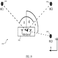
- Fig. 10 shows a further illustrative embodiment of a UWB-based localization system 1000.
- an angle-of-arrival (AOA) based localization system may be envisaged.
- an AOA-based localization system comprises a receiver configured to receive one or more broadcasted messages and to determine angles of arrival of the broadcasted messages, and a processing unit configured to determine the geographic location using said angles of arrival of the broadcasted messages.
- This AOA-based localization system represents an alternative solution to the problem of how to facilitate a reliable and accurate determination of the geographic location of a moving object.
- Fig. 10 shows an example of an AOA-based localization system 1000, which comprises three broadcasters 1004, 1006, 1008 and an AOA device 1002.
- the AOA device 1002 receives the broadcasted messages sent by the broadcasters 1004, 1006, 1008 and measures the angle of arrival of the received signals. Using a triangulation technique the position of the AOA device 1002 can be estimated. It is noted that for a two-dimensional angle of arrival measurement the delay of the different broadcasted messages should be taken into account as well. If a two-dimensional angle of arrival measurement is performed, three broadcasters will be needed for solving the ambiguity of every scenario.
- one broadcast is sufficient for the localization if the angle of arrival data is combined with data provided by an inertial measurement unit. Otherwise, analogous to the TDOA system, two different broadcasts should be combined and the time shift between the broadcasts should be taken into account as well.
- the systems and methods described herein may at least partially be embodied by a computer program or a plurality of computer programs, which may exist in a variety of forms both active and inactive in a single computer system or across multiple computer systems.
- they may exist as software program(s) comprised of program instructions in source code, object code, executable code or other formats for performing some of the steps.
- Any of the above may be embodied on a computer-readable medium, which may include storage devices and signals, in compressed or uncompressed form.
- the term "computer” refers to any electronic device comprising a processor, such as a general-purpose central processing unit (CPU), a specific-purpose processor or a microcontroller.
- a computer is capable of receiving data (an input), of performing a sequence of predetermined operations thereupon, and of producing thereby a result in the form of information or signals (an output).
- the term "computer” will mean either a processor in particular or more generally a processor in association with an assemblage of interrelated elements contained within a single case or housing.
- processor or “processing unit” refers to a data processing circuit that may be a microprocessor, a co-processor, a microcontroller, a microcomputer, a central processing unit, a field programmable gate array (FPGA), a programmable logic circuit, and/or any circuit that manipulates signals (analog or digital) based on operational instructions that are stored in a memory.
- memory refers to a storage circuit or multiple storage circuits such as read-only memory, random access memory, volatile memory, non-volatile memory, static memory, dynamic memory, Flash memory, cache memory, and/or any circuit that stores digital information.
- a "computer-readable medium” or “storage medium” may be any means that can contain, store, communicate, propagate, or transport a computer program for use by or in connection with the instruction execution system, apparatus, or device.
- the computer-readable medium may be, for example but not limited to, an electronic, magnetic, optical, electromagnetic, infrared, or semiconductor system, apparatus, device, or propagation medium.
- the computer-readable medium may include the following: an electrical connection having one or more wires, a portable computer diskette, a random-access memory (RAM), a read-only memory (ROM), an erasable programmable read-only memory (EPROM or Flash memory), an optical fiber, a portable compact disc read-only memory (CDROM), a digital versatile disc (DVD), a Blu-ray disc (BD), and a memory card.
- RAM random-access memory
- ROM read-only memory
- EPROM or Flash memory erasable programmable read-only memory
- CDROM compact disc read-only memory
- DVD digital versatile disc
- BD Blu-ray disc
Landscapes
- Engineering & Computer Science (AREA)
- Radar, Positioning & Navigation (AREA)
- Remote Sensing (AREA)
- Physics & Mathematics (AREA)
- General Physics & Mathematics (AREA)
- Computer Networks & Wireless Communication (AREA)
- Computer Security & Cryptography (AREA)
- Computer Hardware Design (AREA)
- Computing Systems (AREA)
- General Engineering & Computer Science (AREA)
- Signal Processing (AREA)
- Position Fixing By Use Of Radio Waves (AREA)
- Navigation (AREA)
Abstract
Description
- The present disclosure relates to a localization system for determining a geographic location of a movable object. Furthermore, the present disclosure relates to a localization method for determining a geographic location of a movable object, and to a corresponding computer program.
- Localization systems often make use of satellite signals. For example, the global positioning system (GPS) is a satellite-based radio navigation system, which provides geolocation and time information to GPS receivers embedded in, or attached to, moving objects (for example vehicles). Such systems can determine the geographic location of a moving object. When embedded in a vehicle, a GPS receiver can for example enable a navigation system.
- In accordance with a first aspect of the present disclosure, a localization system is provided for determining a geographic location of a movable object, the system comprising: a plurality of anchors, wherein each anchor is configured to receive a broadcasted message through an ultra-wideband communication channel; a processing unit configured to determine the geographic location based on differences between the times of arrival of the broadcasted message at the respective anchors, on relative positions of the anchors and on a predetermined orientation of the movable object.
- In one or more embodiments, the processing unit is configured to determine said differences by selecting one of said anchors as a reference anchor and calculating the differences between the time of arrival of the broadcasted message at the reference anchor and the times of arrival of the broadcasted message at the other anchors.
In one or more embodiments, the times of arrival are based on timestamps which are indicative of a reception time of a predefined marker in the broadcasted message. - In one or more embodiments, the processing unit is configured to receive data indicative of the predetermined orientation of the movable object from an inertial measurement unit.
- In one or more embodiments, the plurality of anchors includes three or more anchors.
- In one or more embodiments, each anchor is configured to receive a further broadcasted message through the ultra-wideband communication channel, and the processing unit is configured to determine the orientation of the movable object based on the differences between the times of arrival of the broadcasted message at the respective anchors, as well as differences between the times of arrival of the further broadcasted message at the respective anchors.
- In one or more embodiments, the broadcasted message includes encrypted content, said encrypted content having been encrypted with a private key, and the processing unit is configured to decrypt the encrypted content using a corresponding public key.
- In one or more embodiments, the broadcasted message contains a broadcast timestamp, and the processing unit is configured to discard the broadcasted message if the broadcast timestamp deviates from a time reference by more than a predefined threshold.
- In one or more embodiments, the time reference is an internal clock value or the time reference is derived from data received through an out-of-band communication channel.
- In one or more embodiments, the processing unit is configured to periodically select one of said anchors as a master anchor for a synchronization process between said anchors.
- In accordance with a second aspect of the present disclosure, a localization system is provided for determining a geographic location of a movable object, the system comprising: a receiver configured to receive one or more broadcasted messages and to determine angles of arrival of the broadcasted messages; a processing unit configured to determine the geographic location using said angles or arrival of the broadcasted messages.
- In one or more embodiments, the movable object is a vehicle.
- In one or more embodiments, a navigation system comprises a localization system of the kind set forth.
- In accordance with a third aspect of the present disclosure, a localization method is conceived for determining a geographic location of a movable object, the method comprising: receiving, by a plurality of anchors, a broadcasted message through an ultra-wideband communication channel; determining, by a processing unit, the geographic location based on differences between the times of arrival of the broadcasted message at the respective anchors, on relative positions of the anchors and on a predetermined orientation of the movable object.
- In accordance with a fourth aspect of the present disclosure, a computer program is provided, comprising executable instructions that, when executed by a localization system, carry out a method of the kind set forth.
- Embodiments will be described in more detail with reference to the appended drawings, in which:
-
Fig. 1 shows an example of a GPS-based localization system; -
Fig. 2 shows an illustrative embodiment of a localization system; -
Fig. 3 shows an illustrative embodiment of a localization method; -
Fig. 4 shows an illustrative embodiment of a TDOA measurement; -
Fig. 5 shows an illustrative embodiment of a UWB-based localization system; -
Fig. 6 shows another illustrative embodiment of a UWB-based localization system; -
Fig. 7 shows a further illustrative embodiment of a UWB-based localization system; -
Fig. 8 shows an illustrative embodiment of a UWB-based navigation system; -
Fig. 9 shows an illustrative embodiment of a state machine for selecting a master anchor; -
Fig. 10 shows a further illustrative embodiment of a UWB-based localization system. - Localization systems often make use of satellite signals. For example, the global positioning system (GPS) is a satellite-based radio navigation system, which provides geolocation and time information to GPS receivers embedded in, or attached to, moving objects (for example vehicles). Such systems can determine the geographic location of a moving object. When embedded in a vehicle, a GPS receiver can for example enable a navigation system.
-
Fig. 1 shows an example of a GPS-basedlocalization system 100. Thesystem 100 includes avehicle 102 whose geographic location should be determined by means ofsatellites buildings satellites localization system 100. - Many cars include a GPS-based navigation system that can be used for determining the current location of a car. Such a GPS-based navigation system typically requires at least 4 signals from different satellites for accurately determining the location of the car. By combining these 4 signals a multilateration-based equation system can be set up for determining the position of the car. For achieving a good localization accuracy, all the signals should be in line-of-sight (LOS) or should at least have a signal propagation time that is very close to the LOS signal propagation time. If the GPS signals are blocked by obstacles, e.g. skyscrapers, the navigation may fail.
Fig. 1 shows an example of acar 102 that is not able to receive the signals of twosatellites skyscrapers - Now discussed are a localization system and a corresponding localization method that facilitate a reliable and accurate determination of the geographic location of a movable object. The movable object can be a car or another vehicle, such as a truck, a forklift truck, a bus, a motorcycle or a bicycle.
-
Fig. 2 shows an illustrative embodiment of alocalization system 200. Thelocalization system 200 comprises a plurality ofanchors processing unit 210. It is noted that theprocessing unit 210 may be a separate component or it may be integrated into one of theanchors localization system 200 may be embedded in, or attached to, a movable object, such as a vehicle. Theanchors processing unit 210 is configured to determine the geographic location of the moving object based on differences between the times of arrival of the broadcasted message at therespective anchors anchors anchors -
Fig. 3 shows an illustrative embodiment of alocalization method 300. Thelocalization method 300 comprises the following steps: at 302, receiving, by a plurality of anchors, a broadcasted message through an UWB communication channel, and at 304, determining, by a processing unit, the geographic location based on differences between the times of arrival of the broadcasted message at the respective anchors, on relative positions of the anchors and on a predetermined orientation of the movable object. In this way, a UWB-based localization method is realized, by means of which the geographic location of a moving object can be detected reliably and accurately. It is noted that the localization method can at least partially be implemented as a computer program. - In particular, a UWB-based broadcasting system offers an accurate localization service that can be used indoor and outdoor. A UWB broadcasting-only system has the advantage that there may be no need for synchronizing the broadcasting devices. The services are working independently from each other. Using a UWB signal has the advantage of enabling an accurate time difference of arrival (TDOA) measurement that can be used for setting up a multilateration-based equation system. Because of the high bandwidth of the UWB signal, the first path of a signal can be detected very accurately. Furthermore, signal reflections have a minor impact on the localization system. A good first path detection is especially important for indoor localization systems because of the high likelihood of having a multipath channel. Since all the devices of the infrastructure may only need to broadcast, the broadcasting devices can be kept very simple and there may be no need for a receiving unit within the broadcasting devices. Since the broadcasters may not need to be synchronized, the infrastructure costs are also reduced.
- In one or more embodiments, the processing unit is configured to determine the differences between the times of arrival of the broadcasted message by selecting one of the anchors as a reference anchor and by calculating the differences between the time of arrival of the broadcasted message at the reference anchor and the times of arrival of the broadcasted message at the other anchors. This results in a practical and effective implementation. Furthermore, in one or more embodiments, the times of arrival are based on timestamps which are indicative of a reception time of a predefined marker in the broadcasted message. This facilitates an accurate determination of the times of arrival.
-
Fig. 4 shows an illustrative embodiment of aTDOA measurement 400. When an anchor receives a message, it stores an accurate timestamp that indicates when the message was received. Timestamps received by multiple synchronized anchors can be used for estimating the TDOA between the anchors.Fig. 4 shows a timing diagram of a TDOA measurement based on a broadcasted message and three receivinganchors - In one or more embodiments, the processing unit is configured to receive data indicative of the predetermined orientation of the movable object from an inertial measurement unit. The inertial measurement unit may be included in the localization system and/or in the same device or object in which the localization system is included. The use of an inertial measurement unit facilitates the predetermination of the orientation of the movable object. Thus, depending for example on the available sensors within a car, received broadcast timestamps can be combined with data received from an inertial measurement unit (IMU) within the car, which can give a feedback about the orientation of the car.
-
Fig. 5 shows an illustrative embodiment of a UWB-basedlocalization system 500. Thelocalization system 500 comprises a plurality ofanchors anchors car 502. Although theanchors car 502 in this schematic overview, the skilled person will appreciate that theanchors car 502. Theanchors external broadcaster 510. In particular, a minimum of threeanchors car 502. If data frommore anchors system 500, which leads to a better measurement accuracy and fault tolerance. Thus, in one or more embodiments, the plurality of anchors includes three or more anchors. For the sake of simplicity, the borders of thecar 502 are oriented along the X and Y axes of the coordinate system. In this example the orientation of thecar 502 is known, for example because it had been tracked during the navigation or it was measured by an IMU. Theanchors car 502 receives the message and generates a receive timestamp. These receive timestamps can be combined with the known relative positions of theanchors broadcaster 510. The combined information can be used for setting up an equation system for determining the position of thecar 502. - For instance, the following equation system can be set up based on the absolute positions of the anchors and the broadcaster:


l A4-BC ... distance between the Broadcaster and A4 XBC ... X-coordinate of BC l A3-BC ... distance between the Broadcaster and A3 YBC ... Y-coordinate of BC l A2-BC ... distance between the Broadcaster and A2 ZBC ... Z-coordinate of BC X A4 ... X-coordinate of A4 X A3 ... X-coordinate of A3 X A2 ... X-coordinate of A2 Y A4 ... Y-coordinate of A4 Y A3 ... Y-coordinate of A3 Y A2 ... Y-coordinate of A2 Z A4 ... Z-coordinate of A4 Z A3 ... Z-coordinate of A3 Z A2 ... Z-coordinate of A2 - Some simplifications can be made based on the known geometry of the car and the placement of the anchors. The variables of the length and width of the car are only placeholders. In a real system the anchors might not be placed at the corners of the car; in that case the distances between the anchors need to be considered instead of the car length and width. The Z-coordinates of the anchors are known, because of the known car height and the known anchor placement. Depending on the shape of the car, the anchors can be placed at different heights. In that case, as long as the heights are known to the system, the position of the car can be estimated. In this example, the following simplifications can be made:


- Clength ... length of the car
- Cwidth ... width of the car
- By combining all these equations, the equation set shown below can be derived. The variables Δl A3 and Δl A2 are place holders for the TDOAs of A3 compared to A4 and of A2 compared to A4, multiplied with the signal propagation speed. These TDOAs can be measured by the synchronized anchor system. The unknown variables in the equation set are marked with braces. Only two different variables are unknown. This means that the equation system can be solved and that the position of the car can be estimated if its orientation is known.


-
Fig. 6 shows another illustrative embodiment of a UWB-based localization system 600. If the orientation of the car is not known, the equation system cannot be solved because the same TDOAs can lead to multiple positions.Fig. 6 shows an example of a system 600 consisting of abroadcaster 604 and acar 602 with three attached anchors. The distances between the car and the anchors are referred to as d1, d2 and d3. It will be appreciated that the distances between thebroadcaster 604 and the anchors are the same even if thecar 602 has a different position. Basically, every position of thecar 602 with the anchors on the dotted lines will lead to the same distances between thebroadcaster 604 and the anchors. As a consequence, thecar 602 cannot determine its position without knowing its orientation. - If the orientation is known, the position of the car can be fully determined without ambiguity by using the equations shown above. The equation set should be adapted according to the orientation of the car. For example, if the car is rotated clockwise by 45° the equation set should be adapted as shown below (equations 1-4). These changes should also be considered in the equations shown above. Independent from the adaptations, the equation system still has only two unknown variables, which means that it can be solved.


- For determining the orientation of the car an inertial measurement unit (IMU) can be used, which provides information about the absolute orientation of the car, for example by means of a magnetometer. If such an IMU-based system cannot be used, the car can be located by combining the TDOA measurement of two broadcasters. Thus, in one or more embodiments, each anchor is configured to receive a further broadcasted message through the ultra-wideband communication channel, and the processing unit is configured to determine the orientation of the movable object based on the differences between the times of arrival of the broadcasted message at the respective anchors, as well as on differences between the times of arrival of the further broadcasted message at the respective anchors.
-
Fig. 7 shows a further illustrative embodiment of a UWB-basedlocalization system 700. The system includes twobroadcasters car 702. If the measurement of twobroadcasters car 702 can be localized because there is only one intersection of the possible car positions calculated based on the received broadcasted messages. For example,position 1 and position 1' are examples of a calculated position based on a single broadcast. However, these positions do not match. Thecalculated position 2 and position 2' are the only positions that match. Therefore, only one possible solution exists. This means that the position of thecar 702 can be estimated without ambiguity by combining message timestamps of the twobroadcasters broadcasters - In one or more embodiments, the broadcasted message includes encrypted content, wherein said encrypted content has been encrypted with a private key, and the processing unit is configured to decrypt the encrypted content using a corresponding public key. In this way, it becomes more difficult to tamper with the broadcasted message. Thus, an emitted broadcast can either contain unencrypted content, for example for non-secure applications, or the content can be encrypted to form a root of trust. If encryption is applied an asymmetric encryption scheme should be used, because the cars receiving the broadcasts should only be able to decrypt broadcasts. If a symmetric encryption would be applied, any device able to decrypt broadcasts would also be able to transmit broadcasts, which should be prevented. When an asymmetric scheme is applied, every broadcaster has a different private key for encrypting messages. Furthermore, every car has the public keys of the broadcasters for decrypting the received content. If the broadcasted content also contains a hash and a timestamp, the encrypted content can also be verified and authenticated. If the private key is not known to an attacker, the attacker can only change the ciphertext. If the ciphertext has been changed by an attacker, the decrypted hash and the plaintext will not match anymore. If the broadcasted message also contains a timestamp, the message can be only reused for a predefined amount of time until a car will notice that a message had been reused by an attacker with the purpose of faking the role of a broadcaster. For the comparison of a timestamp, the car can use an internal clock or an external clock as a time reference. Thus, in one or more embodiments, the broadcasted message contains a broadcast timestamp, and the processing unit is configured to discard the broadcasted message if the broadcast timestamp deviates from a time reference by more than a predefined threshold. In this way, the level of security is increased.
-
Fig. 8 shows an illustrative embodiment of a UWB-basednavigation system 800. The UWB-based navigation system comprises a plurality ofanchors postprocessing unit 808, aninternal reference clock 810, an additional physical layer (PHY) interface, and aposition reporting system 814. The reported position can in turn be used by a navigation module (not shown) which calculates a route from the reported position to a destination. The signal output generated by theanchors postprocessing unit 808 and the results of said processing are transmitted to theposition reporting system 814. Thus, thepostprocessing unit 808 represents a processing unit of the kind set forth. If a broadcast is received, it may be decrypted and the timestamp contained in the plaintext may be extracted. This timestamp may be compared with theinternal reference clock 810. If the difference between the internal clock value and the broadcasted timestamp is too large, the message is discarded. If the timestamp matches with the internal clock value, thepostprocessing unit 808 can start calculating the geographic location of the car. Depending on the data received by theadditional PHY interface 812, thisPHY interface 812 can be also used for generating a time reference, instead of theinternal reference clock 810. Thus, in one or more embodiments, the time reference is an internal clock value of the time reference which is derived from data received through an out-of-bound communication channel (e.g., the additional PHY interface 812). The advantage of using anadditional PHY interface 812 is that said time reference will not be affected by the drift of theinternal reference clock 810, which leads to a more accurate time basis for thesystem 800. Thus, an attacker will have less time left for reusing an already existing broadcast. -
Fig. 9 shows an illustrative embodiment of astate machine 900 for selecting a master anchor. If the anchors are synchronized wirelessly, it is important that every anchor is in line of sight to the master anchor. For such a wireless synchronization the master anchor typically transmits a time reference beacon to the other anchors. If the beacon cannot be received by an anchor, then this anchor cannot be used for the TDOA measurement because of the drifting clock within said anchor. To avoid this, the processing unit may be configured to periodically select one of said anchors as a master anchor for a synchronization process between said anchors. By periodically selecting a new master anchor, the optimal anchor can be chosen for sending the beacon (i.e., the anchor for which it is likely that the beacon will be received by all other anchors).Fig. 9 shows an example of how the best anchor for the wireless synchronization can be estimated. If too many erroneous measurements occur during the UWB navigation, an inter-anchor TOF measurement is started. Based on the TOF measurement the channels and the corresponding first path propagation delay can be estimated. Based on the known first path propagation time and the channel impulse response (CIR), the best anchor for the wireless synchronization can be determined. If the anchor has been selected, the UWB-based navigation can start again. If too many errors occur during navigation, the channel has most likely changed and the procedure for determining the best anchor for the wireless synchronization should be repeated. -
Fig. 10 shows a further illustrative embodiment of a UWB-basedlocalization system 1000. Instead of a TDOA-based localization system of the kind set forth, an angle-of-arrival (AOA) based localization system may be envisaged. In its basic form, such an AOA-based localization system comprises a receiver configured to receive one or more broadcasted messages and to determine angles of arrival of the broadcasted messages, and a processing unit configured to determine the geographic location using said angles of arrival of the broadcasted messages. This AOA-based localization system represents an alternative solution to the problem of how to facilitate a reliable and accurate determination of the geographic location of a moving object. -
Fig. 10 shows an example of an AOA-basedlocalization system 1000, which comprises threebroadcasters AOA device 1002. TheAOA device 1002 receives the broadcasted messages sent by thebroadcasters AOA device 1002 can be estimated. It is noted that for a two-dimensional angle of arrival measurement the delay of the different broadcasted messages should be taken into account as well. If a two-dimensional angle of arrival measurement is performed, three broadcasters will be needed for solving the ambiguity of every scenario. If a three-dimensional angle of arrival can be measured, one broadcast is sufficient for the localization if the angle of arrival data is combined with data provided by an inertial measurement unit. Otherwise, analogous to the TDOA system, two different broadcasts should be combined and the time shift between the broadcasts should be taken into account as well. - The systems and methods described herein may at least partially be embodied by a computer program or a plurality of computer programs, which may exist in a variety of forms both active and inactive in a single computer system or across multiple computer systems. For example, they may exist as software program(s) comprised of program instructions in source code, object code, executable code or other formats for performing some of the steps. Any of the above may be embodied on a computer-readable medium, which may include storage devices and signals, in compressed or uncompressed form.
- As used herein, the term "computer" refers to any electronic device comprising a processor, such as a general-purpose central processing unit (CPU), a specific-purpose processor or a microcontroller. A computer is capable of receiving data (an input), of performing a sequence of predetermined operations thereupon, and of producing thereby a result in the form of information or signals (an output). Depending on the context, the term "computer" will mean either a processor in particular or more generally a processor in association with an assemblage of interrelated elements contained within a single case or housing.
- The term "processor" or "processing unit" refers to a data processing circuit that may be a microprocessor, a co-processor, a microcontroller, a microcomputer, a central processing unit, a field programmable gate array (FPGA), a programmable logic circuit, and/or any circuit that manipulates signals (analog or digital) based on operational instructions that are stored in a memory. The term "memory" refers to a storage circuit or multiple storage circuits such as read-only memory, random access memory, volatile memory, non-volatile memory, static memory, dynamic memory, Flash memory, cache memory, and/or any circuit that stores digital information.
- As used herein, a "computer-readable medium" or "storage medium" may be any means that can contain, store, communicate, propagate, or transport a computer program for use by or in connection with the instruction execution system, apparatus, or device. The computer-readable medium may be, for example but not limited to, an electronic, magnetic, optical, electromagnetic, infrared, or semiconductor system, apparatus, device, or propagation medium. More specific examples (non-exhaustive list) of the computer-readable medium may include the following: an electrical connection having one or more wires, a portable computer diskette, a random-access memory (RAM), a read-only memory (ROM), an erasable programmable read-only memory (EPROM or Flash memory), an optical fiber, a portable compact disc read-only memory (CDROM), a digital versatile disc (DVD), a Blu-ray disc (BD), and a memory card.
- It is noted that the embodiments above have been described with reference to different subject-matters. In particular, some embodiments may have been described with reference to method-type claims whereas other embodiments may have been described with reference to apparatus-type claims. However, a person skilled in the art will gather from the above that, unless otherwise indicated, in addition to any combination of features belonging to one type of subject-matter also any combination of features relating to different subject-matters, in particular a combination of features of the method-type claims and features of the apparatus-type claims, is considered to be disclosed with this document.
- Furthermore, it is noted that the drawings are schematic. In different drawings, similar or identical elements are provided with the same reference signs. Furthermore, it is noted that in an effort to provide a concise description of the illustrative embodiments, implementation details which fall into the customary practice of the skilled person may not have been described. It should be appreciated that in the development of any such implementation, as in any engineering or design project, numerous implementation-specific decisions must be made in order to achieve the developers' specific goals, such as compliance with system-related and business-related constraints, which may vary from one implementation to another. Moreover, it should be appreciated that such a development effort might be complex and time consuming, but would nevertheless be a routine undertaking of design, fabrication, and manufacture for those of ordinary skill.
- Finally, it is noted that the skilled person will be able to design many alternative embodiments without departing from the scope of the appended claims. In the claims, any reference sign placed between parentheses shall not be construed as limiting the claim. The word "comprise(s)" or "comprising" does not exclude the presence of elements or steps other than those listed in a claim. The word "a" or "an" preceding an element does not exclude the presence of a plurality of such elements. Measures recited in the claims may be implemented by means of hardware comprising several distinct elements and/or by means of a suitably programmed processor. In a device claim enumerating several means, several of these means maybe embodied by one and the same item of hardware. The mere fact that certain measures are recited in mutually different dependent claims does not indicate that a combination of these measures cannot be used to advantage.
-
- 100
- GPS-based localization system
- 102
- vehicle
- 104
- satellite
- 106
- satellite
- 108
- building
- 110
- building
- 200
- localization system
- 202
- anchor
- 204
- anchor
- 206
- anchor
- 208
- anchor
- 210
- processing unit
- 300
- localization method
- 302
- receiving, by a plurality of anchors, a broadcasted message through an UWB communication channel
- 304
- determining, by a processing unit, the geographic location of a movable object based on differences between the times of arrival of the broadcasted message at the respective anchors, on relative positions of the anchors and on a predetermined orientation of the movable object
- 400
- TDOA measurement
- 402
- broadcaster
- 404
- anchor
- 406
- anchor
- 408
- anchor
- 410
- timestamp marker
- 412
- difference between arrival times
- 414
- difference between arrival times
- 500
- UWB-based localization system
- 502
- car
- 504
- anchor
- 506
- anchor
- 508
- anchor
- 510
- broadcaster
- 600
- UWB-based localization system
- 602
- car
- 604
- broadcaster
- 700
- UWB-based localization system
- 702
- car
- 704
- broadcaster
- 706
- broadcaster
- 800
- UWB-based navigation system
- 802
- anchor
- 804
- anchor
- 806
- anchor
- 808
- postprocessing unit
- 810
- internal reference clock
- 812
- additional physical layer interface
- 814
- position reporting system
- 900
- state machine for selecting a master anchor
- 902
- inter-anchor time of flight measurement
- 904
- channel impulse response estimation
- 906
- master anchor negotiation
- 908
- start UWB-based navigation
- 910
- wait for erroneous measurements
- 1000
- UWB-based localization system
- 1002
- angle-of-arrival device
- 1004
- broadcaster
- 1006
- broadcaster
- 1008
- broadcaster
Claims (15)
- A localization system for determining a geographic location of a movable object, the system comprising:a plurality of anchors, wherein each anchor is configured to receive a broadcasted message through an ultra-wideband communication channel;a processing unit configured to determine the geographic location based on differences between the times of arrival of the broadcasted message at the respective anchors, on relative positions of the anchors and on a predetermined orientation of the movable object.
- The localization system of claim 1, wherein the processing unit is configured to determine said differences by selecting one of said anchors as a reference anchor and calculating the differences between the time of arrival of the broadcasted message at the reference anchor and the times of arrival of the broadcasted message at the other anchors.
- The localization system of any preceding claim, wherein the times of arrival are based on timestamps which are indicative of a reception time of a predefined marker in the broadcasted message.
- The localization system of any preceding claim, wherein the processing unit is configured to receive data indicative of the predetermined orientation of the movable object from an inertial measurement unit.
- The localization system of any preceding claim, wherein the plurality of anchors includes three or more anchors.
- The localization system of any preceding claim, wherein each anchor is configured to receive a further broadcasted message through the ultra-wideband communication channel, and wherein the processing unit is configured to determine the orientation of the movable object based on the differences between the times of arrival of the broadcasted message at the respective anchors, as well as differences between the times of arrival of the further broadcasted message at the respective anchors.
- The localization system of any preceding claim, wherein the broadcasted message includes encrypted content, said encrypted content having been encrypted with a private key, and wherein the processing unit is configured to decrypt the encrypted content using a corresponding public key.
- The localization system of any preceding claim, wherein the broadcasted message contains a broadcast timestamp, and wherein the processing unit is configured to discard the broadcasted message if the broadcast timestamp deviates from a time reference by more than a predefined threshold.
- The localization system of claim 8, wherein the time reference is an internal clock value or wherein the time reference is derived from data received through an out-of-band communication channel.
- The localization system of any preceding claim, wherein the processing unit is configured to periodically select one of said anchors as a master anchor for a synchronization process between said anchors.
- A localization system for determining a geographic location of a movable object, the system comprising:a receiver configured to receive one or more broadcasted messages and to determine angles of arrival of the broadcasted messages;a processing unit configured to determine the geographic location using said angles or arrival of the broadcasted messages.
- The localization system of any preceding claim, wherein the movable object is a vehicle.
- A navigation system comprising the localization system of any preceding claim.
- A localization method for determining a geographic location of a movable object, the method comprising:receiving, by a plurality of anchors, a broadcasted message through an ultra-wideband communication channel;determining, by a processing unit, the geographic location based on differences between the times of arrival of the broadcasted message at the respective anchors, on relative positions of the anchors and on a predetermined orientation of the movable object.
- A computer program comprising executable instructions that, when executed by a localization system, carry out the method of claim 14.
Priority Applications (3)
| Application Number | Priority Date | Filing Date | Title |
|---|---|---|---|
| EP19202062.6A EP3805778A1 (en) | 2019-10-08 | 2019-10-08 | Localization system and method |
| US17/027,909 US11385320B2 (en) | 2019-10-08 | 2020-09-22 | Localization system and method |
| CN202011040340.9A CN112630803A (en) | 2019-10-08 | 2020-09-28 | Positioning system and method |
Applications Claiming Priority (1)
| Application Number | Priority Date | Filing Date | Title |
|---|---|---|---|
| EP19202062.6A EP3805778A1 (en) | 2019-10-08 | 2019-10-08 | Localization system and method |
Publications (1)
| Publication Number | Publication Date |
|---|---|
| EP3805778A1 true EP3805778A1 (en) | 2021-04-14 |
Family
ID=68242383
Family Applications (1)
| Application Number | Title | Priority Date | Filing Date |
|---|---|---|---|
| EP19202062.6A Pending EP3805778A1 (en) | 2019-10-08 | 2019-10-08 | Localization system and method |
Country Status (3)
| Country | Link |
|---|---|
| US (1) | US11385320B2 (en) |
| EP (1) | EP3805778A1 (en) |
| CN (1) | CN112630803A (en) |
Families Citing this family (7)
| Publication number | Priority date | Publication date | Assignee | Title |
|---|---|---|---|---|
| US11768268B2 (en) * | 2020-12-04 | 2023-09-26 | GM Global Technology Operations LLC | Systems and methods for mobile platform localization using ultra wide band (UWB) signals |
| US11754725B2 (en) * | 2021-02-19 | 2023-09-12 | Westinghouse Air Brake Technologies Corporation | Vehicle location and control system |
| US20220395724A1 (en) * | 2021-06-09 | 2022-12-15 | Huawei Technologies Co., Ltd. | Method and apparatus for flexible local tracking |
| WO2023164530A1 (en) * | 2022-02-25 | 2023-08-31 | Qualcomm Incorporated | Centralized time synchronization for time difference of arrival (tdoa) using ultra-wideband (uwb) |
| WO2023164522A1 (en) * | 2022-02-25 | 2023-08-31 | Qualcomm Incorporated | Distributed time synchronization for time difference of arrival (tdoa) using ultra-wideband (uwb) |
| US20240069141A1 (en) * | 2022-08-31 | 2024-02-29 | Cisco Technology, Inc. | Cluster formation for ultra-wideband time-difference-of-arrival networks |
| CN115190442B (en) * | 2022-09-05 | 2023-06-23 | 济南福深兴安科技有限公司 | Mine accurate positioning system based on UWB |
Citations (3)
| Publication number | Priority date | Publication date | Assignee | Title |
|---|---|---|---|---|
| US20040072582A1 (en) * | 2002-08-20 | 2004-04-15 | Daniel Aljadeff | Method and system for synchronizing location finding measurements in a wireless local area network |
| US20190195981A1 (en) * | 2017-12-22 | 2019-06-27 | Nxp B.V. | Method and system for determining a location of a mobile device |
| US20190294166A1 (en) * | 2015-02-13 | 2019-09-26 | Position Imaging, Inc. | Spatial diveristy for relative position tracking |
Family Cites Families (7)
| Publication number | Priority date | Publication date | Assignee | Title |
|---|---|---|---|---|
| KR20120038353A (en) | 2010-10-13 | 2012-04-23 | 한국전자통신연구원 | Apparatus and method for providing driving information for vehicle based on impulse radio ultra wideband |
| WO2016018031A1 (en) * | 2014-07-31 | 2016-02-04 | Samsung Electronics Co., Ltd. | System and method of providing recommendation content |
| KR101755944B1 (en) | 2015-12-15 | 2017-07-26 | 한양대학교 산학협력단 | Autonomous driving method and system for determing position of car graft on gps, uwb and v2x |
| CN106199511B (en) * | 2016-06-23 | 2019-07-12 | 郑州联睿电子科技有限公司 | VR location tracking system and its location tracking method based on ultra wide band positioning |
| CN107702721A (en) | 2017-11-07 | 2018-02-16 | 云南昆船智能装备有限公司 | A kind of AGV navigation positional devices based on ultra wide band UWB |
| WO2019112647A1 (en) * | 2017-12-08 | 2019-06-13 | Intel IP Corporation | Enhanced time difference of arrival in radio frequency wireless communications |
| CN108089180A (en) | 2017-12-18 | 2018-05-29 | 江苏添仂智能科技有限公司 | Based on UWB sensors as back indicator to the localization method of GPS and inertial navigation system the suspension type rail vehicle corrected |
-
2019
- 2019-10-08 EP EP19202062.6A patent/EP3805778A1/en active Pending
-
2020
- 2020-09-22 US US17/027,909 patent/US11385320B2/en active Active
- 2020-09-28 CN CN202011040340.9A patent/CN112630803A/en active Pending
Patent Citations (3)
| Publication number | Priority date | Publication date | Assignee | Title |
|---|---|---|---|---|
| US20040072582A1 (en) * | 2002-08-20 | 2004-04-15 | Daniel Aljadeff | Method and system for synchronizing location finding measurements in a wireless local area network |
| US20190294166A1 (en) * | 2015-02-13 | 2019-09-26 | Position Imaging, Inc. | Spatial diveristy for relative position tracking |
| US20190195981A1 (en) * | 2017-12-22 | 2019-06-27 | Nxp B.V. | Method and system for determining a location of a mobile device |
Also Published As
| Publication number | Publication date |
|---|---|
| US11385320B2 (en) | 2022-07-12 |
| US20210103023A1 (en) | 2021-04-08 |
| CN112630803A (en) | 2021-04-09 |
Similar Documents
| Publication | Publication Date | Title |
|---|---|---|
| US11385320B2 (en) | Localization system and method | |
| US9485745B2 (en) | Indoor location using a packet synchronized receiver array | |
| US8335173B2 (en) | Inserting time of departure information in frames to support multi-channel location techniques | |
| KR101630890B1 (en) | Wide area positioning system | |
| US7808432B2 (en) | Systems and methods for a high-precision time of arrival ultra-wideband positioning system | |
| US9035827B2 (en) | Positioning using a local wave-propagation model | |
| US9197989B2 (en) | Reference signal transmission method and system for location measurement, location measurement method, device, and system using the same, and time synchronization method and device using the same | |
| US10725144B2 (en) | Transmitters-based localization on freeway | |
| JP2014503147A (en) | System and method for a time-synchronized wireless network access point | |
| CN108490457A (en) | System for detecting personal gnss jammers | |
| KR20140029217A (en) | Method and apparatus for synchronizing navigation data | |
| KR20140029216A (en) | Method and apparatus for synchronizing navigation data | |
| US20210088622A1 (en) | Positioning, navigation, timing, ranging, or beacon transmission system apparatus which utilizes and exploits --- relayed, delayed, or virtual timing marker transmissions of gps, gps alternative, gnss, pnt, electronic, optic, acoustic, or similar signals | |
| KR20140030041A (en) | Method and apparatus for synchronizing navigation data | |
| ES2395642T3 (en) | Improvement of integrity communication in a satellite navigation system | |
| JP2011133331A (en) | Positioning system and positioning method | |
| US20230067774A1 (en) | Transmission receiver system apparatus utilizing relayed, delayed, or virtual timing marker transmissions of gps, gps, alternative, gnss, pnt, electronic, optic, acoustic, or similar signals for positioning, navigation, timing, ranging, or beacon purposes or applications | |
| US11327145B2 (en) | Positioning, navigation, timing, ranging, or beacon transmission system apparatus which utilizes and exploits—relayed, delayed, or virtual timing marker transmissions of GPS, GPS alternative, GNSS, PNT, electronic, optic, acoustic, or similar signals | |
| EP3866524B1 (en) | Uwb communication node and system for facilitating a secure localization of uwb communication nodes | |
| US11333522B2 (en) | Localization system | |
| US20110109504A1 (en) | Alternative Geolocation Capabilities | |
| WO2020098646A1 (en) | Method, device and system for detecting pseudo gnss interference | |
| TW202240200A (en) | Method for certifying the geolocation of a receiver | |
| US10330768B2 (en) | Method implemented by a mobile device for obtaining its position and device implementing this method | |
| Miucic et al. | Position estimate assisted by DSRC for outdoor wireless environments |
Legal Events
| Date | Code | Title | Description |
|---|---|---|---|
| PUAI | Public reference made under article 153(3) epc to a published international application that has entered the european phase |
Free format text: ORIGINAL CODE: 0009012 |
|
| STAA | Information on the status of an ep patent application or granted ep patent |
Free format text: STATUS: THE APPLICATION HAS BEEN PUBLISHED |
|
| AK | Designated contracting states |
Kind code of ref document: A1 Designated state(s): AL AT BE BG CH CY CZ DE DK EE ES FI FR GB GR HR HU IE IS IT LI LT LU LV MC MK MT NL NO PL PT RO RS SE SI SK SM TR |
|
| AX | Request for extension of the european patent |
Extension state: BA ME |
|
| STAA | Information on the status of an ep patent application or granted ep patent |
Free format text: STATUS: REQUEST FOR EXAMINATION WAS MADE |
|
| 17P | Request for examination filed |
Effective date: 20211014 |
|
| RBV | Designated contracting states (corrected) |
Designated state(s): AL AT BE BG CH CY CZ DE DK EE ES FI FR GB GR HR HU IE IS IT LI LT LU LV MC MK MT NL NO PL PT RO RS SE SI SK SM TR |
|
| STAA | Information on the status of an ep patent application or granted ep patent |
Free format text: STATUS: EXAMINATION IS IN PROGRESS |
|
| 17Q | First examination report despatched |
Effective date: 20240104 |