EP3805572A1 - Diffuser, radial turbocompressor - Google Patents
Diffuser, radial turbocompressor Download PDFInfo
- Publication number
- EP3805572A1 EP3805572A1 EP19201593.1A EP19201593A EP3805572A1 EP 3805572 A1 EP3805572 A1 EP 3805572A1 EP 19201593 A EP19201593 A EP 19201593A EP 3805572 A1 EP3805572 A1 EP 3805572A1
- Authority
- EP
- European Patent Office
- Prior art keywords
- diffuser
- dfr
- contour
- flow
- leading edge
- Prior art date
- Legal status (The legal status is an assumption and is not a legal conclusion. Google has not performed a legal analysis and makes no representation as to the accuracy of the status listed.)
- Withdrawn
Links
Images


Classifications
-
- F—MECHANICAL ENGINEERING; LIGHTING; HEATING; WEAPONS; BLASTING
- F04—POSITIVE - DISPLACEMENT MACHINES FOR LIQUIDS; PUMPS FOR LIQUIDS OR ELASTIC FLUIDS
- F04D—NON-POSITIVE-DISPLACEMENT PUMPS
- F04D29/00—Details, component parts, or accessories
- F04D29/40—Casings; Connections of working fluid
- F04D29/42—Casings; Connections of working fluid for radial or helico-centrifugal pumps
- F04D29/44—Fluid-guiding means, e.g. diffusers
- F04D29/441—Fluid-guiding means, e.g. diffusers especially adapted for elastic fluid pumps
- F04D29/444—Bladed diffusers
-
- F—MECHANICAL ENGINEERING; LIGHTING; HEATING; WEAPONS; BLASTING
- F05—INDEXING SCHEMES RELATING TO ENGINES OR PUMPS IN VARIOUS SUBCLASSES OF CLASSES F01-F04
- F05D—INDEXING SCHEME FOR ASPECTS RELATING TO NON-POSITIVE-DISPLACEMENT MACHINES OR ENGINES, GAS-TURBINES OR JET-PROPULSION PLANTS
- F05D2240/00—Components
- F05D2240/10—Stators
- F05D2240/12—Fluid guiding means, e.g. vanes
- F05D2240/121—Fluid guiding means, e.g. vanes related to the leading edge of a stator vane
-
- F—MECHANICAL ENGINEERING; LIGHTING; HEATING; WEAPONS; BLASTING
- F05—INDEXING SCHEMES RELATING TO ENGINES OR PUMPS IN VARIOUS SUBCLASSES OF CLASSES F01-F04
- F05D—INDEXING SCHEME FOR ASPECTS RELATING TO NON-POSITIVE-DISPLACEMENT MACHINES OR ENGINES, GAS-TURBINES OR JET-PROPULSION PLANTS
- F05D2250/00—Geometry
- F05D2250/70—Shape
- F05D2250/71—Shape curved
- F05D2250/713—Shape curved inflexed
Definitions
- the invention relates to a diffuser of a radial turbo compressor, the diffuser extending annularly around a central axis, the diffuser having an inflow which is formed along at least a first section of the flow for an at least largely radial flow by means of a process fluid during operation, the Diffuser has stationary guide vanes, which divides the diffuser at least along a radial section into individual circumferential segments, the guide vanes extending in the direction of flow from an entry edge to an exit edge in the axial center along a mean chord length, the diffuser in the area of the first section has a first diffuser delimitation contour on a first axial side and a second diffuser delimitation contour on a second axial side, the guide vanes extending transversely thereto along at least part of the extent in the direction of flow extend from the first diffuser delimiting contour to the second diffuser delimiting contour along a blade height.
- the diffuser according to the invention is designed bladed. With regard to the blading, a distinction is made between low solidity diffusers [LSD] with low blade overlap (with guide blades that are relatively far apart in the circumferential direction in relation to their radial extent) and channel diffusers - also known as aerodynamic diffusers [AE diffusers] .
- a diffuser according to the invention is preferably designed as an LSD.
- Diffusers for radial machines are already from the EP 2 650 546 A1 known. It is proposed there to arrange the guide vanes of the diffuser in an inclined shape in a standing diffuser arranged behind the impeller (dihedral vanes). With the LSD in particular, this aerodynamic measure is intended to achieve a reduced pressure loss.
- the fin guide vanes In the case of a combined use of fin guide vanes and guide vanes which - unlike the fin guide vanes - extend over the entire axial channel height of the diffuser, the fin guide vanes being upstream of the other guide vanes, it is disadvantageous that the fin guide vanes in the area of their axial end in Flow channel can trigger separation phenomena in the flow. In addition, it is disadvantageous that the rib guide vanes can cause a dead water area extending over part of the channel height downstream, so that in an axial view the flow pattern through the diffuser can also become less uniform through the use of the rib guide vanes, so that positive effects in aerodynamic terms at least to be partially repealed.
- the invention has set itself the task of providing a more uniform flow guidance and at the same time offering the advantage that a separate flow guidance on the part of a cover disk side of the diffuser offers - as is done for example by means of rib guide vanes provided upstream.
- radial, axial, tangential or circumferential direction relate to the initially defined axis around which the diffuser extends in an annular manner. In the case of a turbo compressor or a radial turbo compressor, this axis is coaxial with the axis of rotation of the rotor.
- the invention understands a profile center line to be an imaginary line that extends through the center of a blade profile.
- the blade profile is understood as a two-dimensional shape.
- the profile center line can be constructed in this two-dimensional form, for example by connecting the center points of all inscribed circles by means of a line - the profile center line.
- the diffuser is defined axially by diffuser boundary contours.
- the term “diffuser delimitation contours” is not to be understood here in such a way that the diffuser delimitation contours always have an axial surface normal. Rather, this term is intended to mean that the diffuser delimiting contours in any case have a radial extent and - even if they have an oblique course with respect to the radial or axial - delimit the diffuser in the axial direction.
- Another advantageous development of the invention provides that the axial distance between diffuser delimitation contours widens in the radial direction.
- the diffuser is a flow-conducting component of the stator, which is located downstream of the impeller outlet.
- the flow rate of the process fluid is delayed in the diffuser, so that a pressure build-up results in accordance with Bernoulli's principles.
- the diffuser effect results from the radial increase in the cross-sectional area through which the flow passes.
- a change in the diffuser channel width which usually results from the axial extent of the clear width of the diffuser.
- the diffuser can also extend in a manner deviating from the radial direction. Most diffusers extend largely radially.
- the diffuser channel width is limited by diffuser delimitation contours provided on both sides. In the case of a purely radially extending diffuser without axial expansion, the diffuser delimitation contours also run purely radially.
- the impeller is usually constructed with a wheel disc that connects the impeller to the shaft with a shaft-hub connection.
- the side that does not have the axial suction of the impeller is referred to here as the hub side.
- the other opposite axial side is referred to as the housing side. In the case of impellers that have a cover disk on the housing side, this housing side is also often referred to as the cover disk side.
- the invention understands a blade height as the extension of the blade perpendicular to the main flow direction. If one follows a - for the main flow direction - representative flow thread through the arrangement of the invention, for example through the diffuser, then this extends Flow filament essentially perpendicular to the direction of the blade height. If this flow thread extends approximately centrally through the arrangement, it will be approximately 50% of the blade height.
- stationary guide vanes to mean guide vanes that are firmly connected to the stator and cannot be moved relative to the rest of the stator for the purpose of changing fluidic conditions during operation.
- These guide vanes divide the diffuser at least along a radial section into individual circumferential segments. Such a division does not generally take place by means of purely radially extending guide vanes, but is provided by means of guide vanes extending obliquely to the radial. In the area of the curved leading edge, such a segment division does not exist over the entire axial channel width.
- the invention provides, however, that the guide vanes extend at least in radial sections over the entire width of the channel and that circumferential segments are thereby separated from one another.
- the peripheral segments of claim 1 or the set of patent claims are conceptually synonymous with flow channels between the guide vanes of the diffuser which extend essentially from radially inward to radially outward or are flowed through along this direction.
- the invention understands an average chord length to be a mean value of the chord length averaged over the axial height of the guide vane.
- the chord length is the length of the profile chord - that is, an imaginary connecting line between the profile nose and the profile trailing edge or the leading edge of the guide vane and the trailing edge. Since the profile according to the invention is not constant over the vane height, the terminology of the invention refers to a mean chord length averaged over the height of the guide vane.
- the special feature of the invention is that the curved leading edge of the guide vane is what comes out of the impeller Exiting process fluid leads significantly earlier or further upstream on the cover disk side than on the wheel disk side or on the hub side. Furthermore, the invention ensures a steady transition between the early acceptance of the process fluid on the cover disk side by the flow guidance of the guide vane and the later or more downstream acceptance of the process fluid by the guide vane on the hub side. This smooth transition through the curved leading edge ensures a more harmonious or uniform flow development overall, so that the flow losses in the area are reduced and the flow is less prone to detachment.
- the invention understands the attribute “curved” to mean a “non-angular” course, that is to say a course with a continuous curvature course.
- the terms “curved”, “non-angular profile” and “continuous curvature profile” are synonymous for the invention. As a rule, and preferably, it is an arcuate profile with changing curvature.
- the invention therefore proposes that on the first axial side, the leading edge of the guide vanes is essentially offset upstream along the direction of flow by an offset, the offset being at least 30% of the axial guide vane height or the axial channel width of the diffuser. According to the invention, an even more uniform flow can often be achieved if the offset is at least 50% of the axial diffuser channel width.
- the offset is at least 20% of the mean chord length of the guide vanes.
- An offset of at least 30% of the mean chord length of the guide vanes makes sense aerodynamically.
- the design of the tangential projection of the leading edge is particularly useful if it has at least one turning point in the area of the axial channel width of the diffuser.
- the arrangement according to the invention is particularly expedient and aerodynamically efficient when an angle between the tangents on a tangential projection of the leading edge and a tangential projection of the first diffuser boundary contour is at least 45 °, preferably at least 75 °.
- An advantageous development provides that the angle between the tangent on a tangential projection of the leading edge and a tangential projection of the second diffuser boundary contour is at least 45 °, preferably at least 75 °.
- the design of the curved leading edge according to the invention is particularly expedient if the point of inflection of the tangential projection of the leading edge is arranged closer to the first diffuser delimiting contour than to the second diffuser delimiting contour. In this case, it makes sense, in the event that there are several turning points of this type, that this criterion is applicable for at least one turning point.
- the invention also relates to a radial turbo compressor with a diffuser of the design according to the invention.
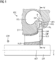
- FIG. 1 shows a centrifugal compressor RTC with a diffuser DFR and an impeller IMP arranged upstream of the diffuser DFR.
- the impeller IMP and the diffuser DFR extend annularly along a circumferential direction CDR of an axis X with an axis of rotation ROT.
- the impeller IMP is fastened in a specific axial position to a shaft SHT which is rotatably mounted about the axis of rotation ROT or the axis X arranged coaxially to the axis of rotation ROT.
- the impeller IMP has a wheel disk H, impeller blades BLD and a cover disk SHR, the impeller blades BLD being attached between the wheel disk H and the cover disk SHR, forming flow channels.
- a process fluid PFL is sucked in axially and deflected outwards in the radial direction, where it exits the rotating impeller IMP during operation and enters a static diffuser DFR.
- the process fluid PFL flows from the diffuser DFR into a collecting spiral VOL. From there, the process fluid PFL from the radial turbo compressor RTC is fed to units located downstream in a manner not shown.
- FIGS 2-4 show schematically that in the Figure 1 with II designated detail, whereby different variants of this detail are shown.
- the guide vane VNS shown of the diffuser DFR each has a curved leading edge LDG according to the invention.
- a maximum chord length XCL is indicated in each of the figures, and the minimum chord length YCL is also indicated. Schematically drawn between these two extremes Values is a mean chord length MCL.
- An offset between the leading edge LDG on the first axial side and the leading edge LDG on the second axial side is indicated according to the invention with an offset DCL.
- the inlet edge LDG which is offset upstream by the offset DCL on the first axial side, guides the process fluid entering the diffuser DFR a little further upstream, so that the inhomogeneity of the process fluid flowing out of the impeller IMP over the axial channel width is better taken into account.
- the guide vane VNS extends at least over a partial section axially over the entire channel width with an axial guide vane height AVH.
- the tangential projection of the leading edge LDG has at least one turning point WP, which is preferably closer to the first diffuser delimiting contour DC1 than to the second diffuser delimiting contour DC2.
- An angle ⁇ between tangents on a tangential projection of the leading edge LDG and a tangential projection of the first diffuser boundary contour DC1 is preferably at least 75 ° ( Figure 3 ), particularly preferably at least 90 ° ( Figures 2 , 4th ).
- the angle ⁇ means the angle between the two tangents that defines the free space between the first diffuser boundary contour DC1 and the leading edge LDG of the guide vane VNS and not the angle that is within the solid or the material of the guide vane VNS.
- a second angle ⁇ located on the opposite, second diffuser delimiting contour DC2 preferably has the same conditions as in FIG Figures 2, 3 shown.
- Figure 5 shows an in Figure 3 section illustrated as VV, which shows schematically the arrangement of the guide vanes VNS in the diffuser DFR.
- the guide vanes VNS extend from a leading edge LDG up to a trailing edge TRG, with a chord length CDL or a mean chord length MCL or, depending on the arrangement of the section along the axial height AVH, a minimum chord length YCL or a maximum chord length XCL are characteristic for the respective profile.
Landscapes
- Engineering & Computer Science (AREA)
- Mechanical Engineering (AREA)
- General Engineering & Computer Science (AREA)
- Structures Of Non-Positive Displacement Pumps (AREA)
Abstract
Die Erfindung betrifft einen Diffusor (DFR) eines Radialturboverdichters (RTC), wobei der Diffusor (DFR) sich ringförmig um eine zentrale Achse (X) erstreckt, wobei der Diffusor (DFR) eine Zuströmung (INL) aufweist, die entlang zumindest eines ersten Abschnitts (SG1) der Durchströmung für eine zumindest weitestgehend radiale Durchströmung mittels eines Prozessfluids (PFL) im Betrieb ausgebildet ist, wobei der Diffusor (DFR) stehende Leitschaufeln (VNS) aufweist, die den Diffusor (DFR) zumindest entlang eines radialen Abschnitts in einzelne Umfangssegmente aufteilt, wobei sich die Leitschaufeln (VNS) in Richtung der Durchströmung von einer Eintrittskante (LDG) bis zu einer Austrittskante (TRG) im axialen Mittel entlang einer mittleren Sehnenlänge (MCL) erstrecken, wobei der Diffusor (DFR) im Bereich des ersten Abschnitts (SG1) auf einer ersten axialen Seite (SRS) eine erste Diffusorbegrenzungskontur (DC1) und auf einer zweiten axialen Seite (HBS) eine zweite Diffusorbegrenzungskontur (DC2) aufweist, wobei sich die Leitschaufeln (VNS) zumindest entlang eines Teils der Erstreckung in Durchströmungsrichtung quer dazu von der ersten Diffusorbegrenzungskontur (DC1) bis zur zweiten Diffusorbegrenzungskontur (DC2) entlang einer Schaufelhöhe (AVH) erstrecken. Zur Reduktion von Strömungsverlusten schlägt die Erfindung vor, dass die Eintrittskante (LDG) im tangentialer Projektion geschwungen ausgebildet ist, wobei die Eintrittskante (LDG) seitens der ersten axialen Seite (SRS) im Wesentlichen entlang der Richtung der Durchströmung um einen Versatz (DCL) stromaufwärts versetzt ist, wobei gilt: DCL≥0,3*AVH.The invention relates to a diffuser (DFR) of a radial turbo compressor (RTC), the diffuser (DFR) extending in a ring around a central axis (X), the diffuser (DFR) having an inflow (INL) that runs along at least a first section (SG1) the flow is designed for an at least largely radial flow by means of a process fluid (PFL) during operation, the diffuser (DFR) having stationary guide vanes (VNS) which divides the diffuser (DFR) at least along a radial section into individual circumferential segments , the guide vanes (VNS) extending in the direction of flow from a leading edge (LDG) to a trailing edge (TRG) in the axial center along a mean chord length (MCL), the diffuser (DFR) in the area of the first section (SG1 ) on a first axial side (SRS) a first diffuser delimitation contour (DC1) and on a second axial side (HBS) a second diffuser delimitation contour (D C2), the guide vanes (VNS) extending at least along part of the extent in the flow direction transversely thereto from the first diffuser delimitation contour (DC1) to the second diffuser delimitation contour (DC2) along a vane height (AVH). To reduce flow losses, the invention proposes that the leading edge (LDG) is curved in the tangential projection, with the leading edge (LDG) on the first axial side (SRS) essentially along the direction of flow by an offset (DCL) upstream is offset, where: DCL≥0.3 * AVH.
Description
Die Erfindung betrifft einen Diffusor eines Radialturboverdichters, wobei der Diffusor sich ringförmig um eine zentrale Achse erstreckt, wobei der Diffusor eine Zuströmung aufweist, die entlang zumindest eines ersten Abschnitts der Durchströmung für eine zumindest weitestgehend radiale Durchströmung mittels eines Prozessfluids im Betrieb ausgebildet ist, wobei der Diffusor stehende Leitschaufeln aufweist, die den Diffusor zumindest entlang eines radialen Abschnitts in einzelne Umfangssegmente aufteilt, wobei sich die Leitschaufeln in Richtung der Durchströmung von einer Eintrittskante bis zu einer Austrittskante im axialen Mittel entlang einer mittleren Sehnenlänge erstrecken, wobei der Diffusor im Bereich des ersten Abschnitts auf einer ersten axialen Seite eine erste Diffusorbegrenzungskontur und auf einer zweiten axialen Seite eine zweite Diffusorbegrenzungskontur aufweist, wobei sich die Leitschaufeln zumindest entlang eines Teils der Erstreckung in Durchströmungsrichtung quer dazu von der ersten Diffusorbegrenzungskontur bis zur zweiten Diffusorbegrenzungskontur entlang einer Schaufelhöhe erstrecken.The invention relates to a diffuser of a radial turbo compressor, the diffuser extending annularly around a central axis, the diffuser having an inflow which is formed along at least a first section of the flow for an at least largely radial flow by means of a process fluid during operation, the Diffuser has stationary guide vanes, which divides the diffuser at least along a radial section into individual circumferential segments, the guide vanes extending in the direction of flow from an entry edge to an exit edge in the axial center along a mean chord length, the diffuser in the area of the first section has a first diffuser delimitation contour on a first axial side and a second diffuser delimitation contour on a second axial side, the guide vanes extending transversely thereto along at least part of the extent in the direction of flow extend from the first diffuser delimiting contour to the second diffuser delimiting contour along a blade height.
Bei Radialverdichtern verlässt das Fluid das Laufrad nach radial außen und gelangt von dort in den Diffusor, welcher typischerweise ebenfalls radial von innen nach außen durchströmt wird. Der Diffusor gemäß der Erfindung ist beschaufelt ausgeführt. Hinsichtlich der Beschaufelung wird zwischen Low-Solidity-Diffusoren [LSD] mit geringer Schaufelüberdeckung (mit Leitschaufeln, die einen verhältnismäßig großen Abstand zueinander in Umfangsrichtung im Verhältnis zu deren Radialerstreckung aufweisen) und Kanaldiffusoren - auch als aerodynamische Diffusoren [AE-Diffusor] bezeichnet - unterschieden. Ein erfindungsgemäßer Diffusor ist vorzugsweise als LSD ausgebildet.In the case of radial compressors, the fluid leaves the impeller radially outwards and from there enters the diffuser, which is typically also flowed through radially from the inside to the outside. The diffuser according to the invention is designed bladed. With regard to the blading, a distinction is made between low solidity diffusers [LSD] with low blade overlap (with guide blades that are relatively far apart in the circumferential direction in relation to their radial extent) and channel diffusers - also known as aerodynamic diffusers [AE diffusers] . A diffuser according to the invention is preferably designed as an LSD.
Diffusoren für Radialmaschinen sind bereits aus der
Aus den
Aus der
Bei einem kombinierten Einsatz von Rippenleitschaufeln und Leitschaufeln, die sich - anders als die Rippenleitschaufeln - über die gesamte axiale Kanalhöhe des Diffusors erstrecken, wobei die Rippenleitschaufeln sich stromaufwärts der anderen Leitschaufeln befinden, ist es von Nachteil, dass die Rippenleitschaufeln im Bereich ihres axialen Abschlusses im Strömungskanal Ablösungserscheinungen in der Durchströmung auslösen können. Daneben ist es nachteilhaft, dass die Rippenleitschaufeln einen sich über einen Teil der Kanalhöhe erstreckenden Totwasserbereich stromabwärts verursachen können, so dass in axialer Betrachtungsweise das Strömungsbild durch den Diffusor durch den Einsatz der Rippenleitschaufeln zusätzlich weniger gleichmäßig werden kann, so dass positive Wirkungen in aerodynamischer Hinsicht zumindest teilweise wieder aufgehoben werden.In the case of a combined use of fin guide vanes and guide vanes which - unlike the fin guide vanes - extend over the entire axial channel height of the diffuser, the fin guide vanes being upstream of the other guide vanes, it is disadvantageous that the fin guide vanes in the area of their axial end in Flow channel can trigger separation phenomena in the flow. In addition, it is disadvantageous that the rib guide vanes can cause a dead water area extending over part of the channel height downstream, so that in an axial view the flow pattern through the diffuser can also become less uniform through the use of the rib guide vanes, so that positive effects in aerodynamic terms at least to be partially repealed.
Insbesondere motiviert von der Vermeidung unverhältnismäßiger Ablöseerscheinungen hat es sich die Erfindung zur Aufgabe gemacht, eine gleichmäßigere Strömungsführung bereitzustellen und gleichzeitig den Vorteil anzubieten, den eine gesonderte Strömungsführung seitens einer Deckscheibenseite des Diffusors bietet - wie diese beispielsweise mittels stromaufwärts vorgesehener Rippenleitschaufeln erfolgt - bereitzustellen.In particular, motivated by the avoidance of disproportionate detachment phenomena, the invention has set itself the task of providing a more uniform flow guidance and at the same time offering the advantage that a separate flow guidance on the part of a cover disk side of the diffuser offers - as is done for example by means of rib guide vanes provided upstream.
Zur Lösung des Problems wird ein Diffusor bzw. ein Radialturboverdichter mit einem solchen Diffusor mit den eingangs definierten Merkmalen vorgeschlagen, der die zusätzlichen Merkmale des Kennzeichens des Anspruchs 1 aufweist. Die rückbezogenen Unteransprüchen beinhalten vorteilhafte Weiterbildungen der Erfindung.To solve the problem, a diffuser or a radial turbo compressor with such a diffuser with the features defined at the outset is proposed, which has the additional features of the characterizing part of claim 1. The dependent claims referring back contain advantageous developments of the invention.
Begriffe, wie radial, axial, tangential oder Umfangsrichtung beziehen sich auf die eingangs definierte Achse, um die sich der Diffusor ringförmig erstreckt. Diese Achse ist im Falle eines Turboverdichters bzw. eines Radialturboverdichters koaxial zu der Drehachse des Rotors.Terms such as radial, axial, tangential or circumferential direction relate to the initially defined axis around which the diffuser extends in an annular manner. In the case of a turbo compressor or a radial turbo compressor, this axis is coaxial with the axis of rotation of the rotor.
Sämtliche Winkelangaben beziehen sich hierbei stets auf die gegenständlichen Winkel an den tatsächlichen geometrischen Formen - kurz: Metallwinkel.All angle details always relate to the actual angles on the actual geometric shapes - in short: metal angles.
Unter einer Profilmittellinie versteht die Erfindung eine gedachte Linie, die sich durch die Mitte eines Schaufelprofiles erstreckt. Hierbei wird das Schaufelprofil als eine zweidimensionale Form aufgefasst. Die Profilmittellinie kann in dieser zweidimensionalen Form konstruiert werden, indem beispielsweise die Mittelpunkte aller eingeschriebenen Kreise mittels einer Linie - der Profilmittellinie - verbunden werden.The invention understands a profile center line to be an imaginary line that extends through the center of a blade profile. Here, the blade profile is understood as a two-dimensional shape. The profile center line can be constructed in this two-dimensional form, for example by connecting the center points of all inscribed circles by means of a line - the profile center line.
Der Diffusor wird axial von Diffusorbegrenzungskonturen definiert. Hierbei ist der Begriff "Diffusorbegrenzungskonturen" nicht derart zu verstehen, dass die Diffusorbegrenzungskonturen immer eine axiale Flächennormale aufweisen. Vielmehr soll dieser Begriff bedeuten, dass die Diffusorbegrenzungskonturen jedenfalls eine Radialerstreckung aufweisen und - auch wenn sie einen gegenüber der Radialen oder Axialen schrägen Verlauf aufweisen - den Diffusor in Axialrichtung begrenzen. Eine weitere vorteilhafte Weiterbildung der Erfindung sieht vor, dass sich in radialer Richtung der Axialabstand zwischen Diffusorbegrenzungskonturen aufweitet.The diffuser is defined axially by diffuser boundary contours. The term “diffuser delimitation contours” is not to be understood here in such a way that the diffuser delimitation contours always have an axial surface normal. Rather, this term is intended to mean that the diffuser delimiting contours in any case have a radial extent and - even if they have an oblique course with respect to the radial or axial - delimit the diffuser in the axial direction. Another advantageous development of the invention provides that the axial distance between diffuser delimitation contours widens in the radial direction.
Insbesondere im Falle des Radialturboverdichters ist der Diffusor ein strömungsleitendes Bauteil des Stators, das sich stromabwärts des Laufradaustritts befindet. In dem Diffusor wird in der Regel die Strömungsgeschwindigkeit des Prozessfluids verzögert, so dass sich gemäß den Gesetzmäßigkeiten von Bernoulli ein Druckaufbau ergibt.In the case of the radial turbo compressor in particular, the diffuser is a flow-conducting component of the stator, which is located downstream of the impeller outlet. As a rule, the flow rate of the process fluid is delayed in the diffuser, so that a pressure build-up results in accordance with Bernoulli's principles.
Im Falle des Radialturboverdichters und eines sich im Wesentlichen radial nach außen erstreckenden Diffusors ergibt sich die Diffusor-Wirkung schon allein durch die radiale Zunahme der durchströmten Querschnittsfläche. Zusätzlich von Bedeutung ist eine Veränderung der Diffusorkanalbreite, die sich im Regelfall als die axiale Erstreckung der lichten Weite des Diffusors ergibt. Grundsätzlich kann sich der Diffusor auch abweichend von der Radialrichtung erstrecken. Die meisten Diffusoren erstrecken sich weitestgehend radial. Die Diffusorkanalbreite wird begrenzt durch an beiden Seiten vorgesehenen Diffusorbegrenzungskonturen. Im Falle eines sich rein radial erstreckenden Diffusors ohne axiale Aufweitung laufen die Diffusorbegrenzungskonturen ebenfalls rein radial. Aufgrund der axialen Ansaugung eines Radialturboverdichters und der radialen Ausgabe des Prozessfluids aus dem Laufrad findet in dem Laufrad eine Umlenkung von axial nach radial statt. Das Laufrad ist hierbei in der Regel mit einer Radscheibe aufgebaut, die mit einer Welle-Nabe-Verbindung das Laufrad mit der Welle verbindet. Diejenige Seite, die nicht die axiale Ansaugung des Laufrades aufweist, wird hierbei als die Nabenseite bezeichnet. Die andere gegenüberliegende Axialseite wird als Gehäuseseite bezeichnet. Bei Laufrädern, die gehäuseseitig eine Deckscheibe aufweisen, wird diese Gehäuseseite auch häufig als die Deckscheibenseite bezeichnet.In the case of the radial turbo compressor and a diffuser that extends essentially radially outward, the diffuser effect results from the radial increase in the cross-sectional area through which the flow passes. Also of importance is a change in the diffuser channel width, which usually results from the axial extent of the clear width of the diffuser. In principle, the diffuser can also extend in a manner deviating from the radial direction. Most diffusers extend largely radially. The diffuser channel width is limited by diffuser delimitation contours provided on both sides. In the case of a purely radially extending diffuser without axial expansion, the diffuser delimitation contours also run purely radially. Due to the axial suction of a radial turbo compressor and the radial output of the process fluid from the impeller, a deflection from axial to radial takes place in the impeller. The impeller is usually constructed with a wheel disc that connects the impeller to the shaft with a shaft-hub connection. The side that does not have the axial suction of the impeller is referred to here as the hub side. The other opposite axial side is referred to as the housing side. In the case of impellers that have a cover disk on the housing side, this housing side is also often referred to as the cover disk side.
Unter einer Schaufelhöhe versteht die Erfindung die Erstreckung der Schaufel senkrecht zur Hauptströmungsrichtung. Folgt man einem - für die Hauptströmungsrichtung - repräsentativen Strömungsfaden durch die Anordnung der Erfindung, beispielsweise durch den Diffusor, so erstreckt sich dieser Strömungsfaden im Wesentlichen senkrecht zur Richtung der Schaufelhöhe. Erstreckt sich dieser Strömungsfaden in etwa mittig durch die Anordnung wird er in etwa bei 50% der Schaufelhöhe liegen.The invention understands a blade height as the extension of the blade perpendicular to the main flow direction. If one follows a - for the main flow direction - representative flow thread through the arrangement of the invention, for example through the diffuser, then this extends Flow filament essentially perpendicular to the direction of the blade height. If this flow thread extends approximately centrally through the arrangement, it will be approximately 50% of the blade height.
Unter stehenden Leitschaufeln versteht die Erfindung Leitschaufeln, die fest mit dem Stator verbunden sind und sich nicht zum Zwecke der Veränderung strömungstechnischer Bedingungen im Betrieb relativ zu dem Rest des Stators bewegen lassen. Diese Leitschaufeln teilen den Diffusor zumindest entlang eines radialen Abschnitts in einzelne Umfangssegmente auf. Eine derartige Aufteilung erfolgt in der Regel nicht strickt mittels rein radial verlaufender Leitschaufeln, sondern ist mittels schräg zur Radialen sich erstreckender Leitschaufeln gegeben. In dem Bereich der geschwungenen Eintrittskante ist eine derartige Segmentaufteilung nicht über die gesamte axiale Kanalbreite gegeben. Die Erfindung sieht jedoch vor, dass zumindest radial-abschnittsweise die Leitschaufeln sich über die gesamte Kanalbreite erstrecken und dadurch Umfangssegmente voneinander getrennt sind. Die Umfangssegmente des Anspruchs 1 bzw. des Patentanspruchssatzes sind begrifflich synonym mit Strömungskanälen zwischen den Leitschaufeln des Diffusors, die sich im Wesentlichen von radial innen nach radial außen erstrecken bzw. entlang dieser Richtung durchströmt werden.The invention understands stationary guide vanes to mean guide vanes that are firmly connected to the stator and cannot be moved relative to the rest of the stator for the purpose of changing fluidic conditions during operation. These guide vanes divide the diffuser at least along a radial section into individual circumferential segments. Such a division does not generally take place by means of purely radially extending guide vanes, but is provided by means of guide vanes extending obliquely to the radial. In the area of the curved leading edge, such a segment division does not exist over the entire axial channel width. The invention provides, however, that the guide vanes extend at least in radial sections over the entire width of the channel and that circumferential segments are thereby separated from one another. The peripheral segments of claim 1 or the set of patent claims are conceptually synonymous with flow channels between the guide vanes of the diffuser which extend essentially from radially inward to radially outward or are flowed through along this direction.
Unter einer mittleren Sehnenlänge versteht die Erfindung einen Mittelwert der Sehnenlänge gemittelt über die axiale Höhe der Leitschaufel. Die Sehnenlänge ist die Länge der Profilsehne - also einer gedachten Verbindungslinie zwischen der Profilnase und der Profilhinterkante bzw. der Eintrittskante der Leitschaufel und der Austrittskante. Da das Profil nach der Erfindung über die Schaufelhöhe nicht konstant ist, nimmt die Begriffswelt der Erfindung Bezug auf eine mittlere Sehnenlänge gemittelt über die Höhe der Leitschaufel.The invention understands an average chord length to be a mean value of the chord length averaged over the axial height of the guide vane. The chord length is the length of the profile chord - that is, an imaginary connecting line between the profile nose and the profile trailing edge or the leading edge of the guide vane and the trailing edge. Since the profile according to the invention is not constant over the vane height, the terminology of the invention refers to a mean chord length averaged over the height of the guide vane.
Die Besonderheit der Erfindung liegt darin, dass die geschwungene Eintrittskante der Leitschaufel das aus dem Laufrad austretende Prozessfluid auf der Deckscheibenseite signifikant früher bzw. weiter stromaufwärts führt als seitens der Radscheibe bzw. auf der Nabenseite. Weiterhin sorgt die Erfindung für einen stetigen Übergang zwischen der frühen Annahme des Prozessfluids auf der Deckscheibenseite durch die Strömungsführung der Leitschaufel und der späteren bzw. stromabwärtigeren Annahme des Prozessfluids durch die Leitschaufel auf der Nabenseite. Dieser gleitende Übergang durch die geschwungene Eintrittskante sorgt insgesamt für eine harmonischere oder gleichmäßigere Strömungsentwicklung, so dass die Strömungsverluste in dem Bereich reduziert sind und die Strömung weniger zur Ablösung neigt.The special feature of the invention is that the curved leading edge of the guide vane is what comes out of the impeller Exiting process fluid leads significantly earlier or further upstream on the cover disk side than on the wheel disk side or on the hub side. Furthermore, the invention ensures a steady transition between the early acceptance of the process fluid on the cover disk side by the flow guidance of the guide vane and the later or more downstream acceptance of the process fluid by the guide vane on the hub side. This smooth transition through the curved leading edge ensures a more harmonious or uniform flow development overall, so that the flow losses in the area are reduced and the flow is less prone to detachment.
Unter dem Attribut "geschwungen ausgebildet" versteht die Erfindung einen "nicht eckigen" Verlauf also einen Verlauf mit stetigem Krümmungsverlauf. In diesem Zusammenhang sind die Begriffe "geschwungen ausgebildet", ""nicht eckiger Verlauf" und "stetigem Krümmungsverlauf" für die Erfindung synonym. In der Regel und bevorzugt handelt es sich um einen bogenförmigen Verlauf mit sich verändernder Krümmung.The invention understands the attribute “curved” to mean a “non-angular” course, that is to say a course with a continuous curvature course. In this context, the terms “curved”, “non-angular profile” and “continuous curvature profile” are synonymous for the invention. As a rule, and preferably, it is an arcuate profile with changing curvature.
Die Erfindung schlägt daher vor, dass seitens der ersten axialen Seite die Eintrittskante der Leitschaufeln im Wesentlichen entlang der Richtung der Durchströmung um einen Versatz stromaufwärts versetzt ist, wobei der Versatz mindestens 30% der axialen Leitschaufelhöhe bzw. der axialen Kanalbreite des Diffusors beträgt. Eine noch gleichmäßigere Strömung kann nach der Erfindung häufig erreicht werden, wenn der Versatz mindestens 50% der axialen Diffusorkanalbreite beträgt.The invention therefore proposes that on the first axial side, the leading edge of the guide vanes is essentially offset upstream along the direction of flow by an offset, the offset being at least 30% of the axial guide vane height or the axial channel width of the diffuser. According to the invention, an even more uniform flow can often be achieved if the offset is at least 50% of the axial diffuser channel width.
Eine weitere vorteilhafte Möglichkeit nach der Erfindung, den erfindungsgemäßen Versatz hinsichtlich der Tangentialprojektion der Eintrittskanten zu bemessen, besteht darin, dass der Versatz mindestens 20% der mittleren Sehnenlänge der Leitschaufeln beträgt. Aerodynamisch ist ein Versatzes von mindestens 30% der mittleren Sehnenlänge der Leitschaufeln sinnvoll.Another advantageous possibility according to the invention of dimensioning the offset according to the invention with regard to the tangential projection of the leading edges is that the offset is at least 20% of the mean chord length of the guide vanes. An offset of at least 30% of the mean chord length of the guide vanes makes sense aerodynamically.
Besonders zweckmäßig ist die Gestaltung der tangentialen Projektion der Eintrittskante, wenn diese mindestens einen Wendepunkt im Bereich der axialen Kanalbreite des Diffusors aufweist. Besonders zweckmäßig und aerodynamisch effizient wird die Anordnung nach der Erfindung, wenn ein Winkel zwischen den Tangenten an einer tangentialen Projektion der Eintrittskante und einer tangentialen Projektion der ersten Diffusorbegrenzungskontur mindestens 45° beträgt, bevorzugt mindestens 75°. Eine vorteilhafte Weiterbildung sieht vor, dass der Winkel zwischen der Tangente an einer tangentialen Projektion der Eintrittskante und einer tangentialen Projektion der zweiten Diffusorbegrenzungskontur mindestens 45° beträgt, bevorzugt mindestens 75°.The design of the tangential projection of the leading edge is particularly useful if it has at least one turning point in the area of the axial channel width of the diffuser. The arrangement according to the invention is particularly expedient and aerodynamically efficient when an angle between the tangents on a tangential projection of the leading edge and a tangential projection of the first diffuser boundary contour is at least 45 °, preferably at least 75 °. An advantageous development provides that the angle between the tangent on a tangential projection of the leading edge and a tangential projection of the second diffuser boundary contour is at least 45 °, preferably at least 75 °.
Besonders zweckmäßig ist die Gestaltung der erfindungsgemäßen geschwungenen Eintrittskante, wenn der Wendepunkt der tangentialen Projektion der Eintrittskante näher an der ersten Diffusorbegrenzungskontur angeordnet ist als an der zweiten Diffusorbegrenzungskontur. Hierbei ist es sinnvoll, für den Fall das mehrere Wendepunkte dieser Art vorliegen, dass dieses Kriterium für mindestens einen Wendepunkt zutreffend ist.The design of the curved leading edge according to the invention is particularly expedient if the point of inflection of the tangential projection of the leading edge is arranged closer to the first diffuser delimiting contour than to the second diffuser delimiting contour. In this case, it makes sense, in the event that there are several turning points of this type, that this criterion is applicable for at least one turning point.
Weiterhin bezieht sich die Erfindung auf einen Radialturboverdichter mit einem Diffusor der erfindungsgemäßen Ausbildung.The invention also relates to a radial turbo compressor with a diffuser of the design according to the invention.
Im Folgenden ist die Erfindung anhand verschiedener Figuren zum besseren Verständnis unter Darstellung bevorzugter Ausführungsbeispiele illustriert. Es zeigen:
- Figur 1
- einen schematischen Längsschnitt entlang einer Drehachse durch einen Radialturboverdichter mit einem erfindungsgemäßen Diffusor,
- Figuren 2, 3, 4
- jeweils das Detail II aus
Figur 1 in verschiedenen Varianten, - Figur 5
- einen Schnitt V-V entlang einer Hauptströmungsrichtung gemäß
Figur 1 .
- Figure 1
- a schematic longitudinal section along an axis of rotation through a radial turbo compressor with a diffuser according to the invention,
- Figures 2, 3, 4
- detail II in each case
Figure 1 in different variants, - Figure 5
- a section VV along a main flow direction according to
Figure 1 .
Eine vorteilhafte Weiterbildung des erfindungsgemäßen Radialverdichters RTC ist gegeben durch die Anordnung eines offenen Laufrads IMP ohne Deckscheibe SHR. Diese Variante ist nicht gesondert dargestellt, sondern die Deckscheibe SHR - dargestellt in
Aus dem Diffusor DFR strömt das Prozessfluid PFL in eine Sammelspirale VOL ein. Von dort aus wird das Prozessfluid PFL aus dem Radialturboverdichter RTC in nicht dargestellter Weise stromabwärts befindlichen Aggregaten zugeführt.The process fluid PFL flows from the diffuser DFR into a collecting spiral VOL. From there, the process fluid PFL from the radial turbo compressor RTC is fed to units located downstream in a manner not shown.
Die
Die Variante, die in
Claims (9)
wobei der Diffusor (DFR) sich ringförmig um eine zentrale Achse (X) erstreckt,
wobei der Diffusor (DFR) eine Zuströmung (INL) aufweist,
die entlang zumindest eines ersten Abschnitts (SG1) der Durchströmung für eine zumindest weitestgehend radiale Durchströmung mittels eines Prozessfluids (PFL) im Betrieb ausgebildet ist,
wobei der Diffusor (DFR) stehende Leitschaufeln (VNS) aufweist, die den Diffusor (DFR) zumindest entlang eines radialen Abschnitts in einzelne Umfangssegmente aufteilt,
wobei sich die Leitschaufeln (VNS) in Richtung der Durchströmung von einer Eintrittskante (LDG) bis zu einer Austrittskante (TRG) im axialen Mittel entlang einer mittleren Sehnenlänge (MCL) erstrecken,
wobei der Diffusor (DFR) im Bereich des ersten Abschnitts (SG1) auf einer ersten axialen Seite (SRS) eine erste Diffusorbegrenzungskontur (DC1) und auf einer zweiten axialen Seite (HBS) eine zweite Diffusorbegrenzungskontur (DC2) aufweist,
wobei sich die Leitschaufeln (VNS) zumindest entlang eines Teils der Erstreckung in Durchströmungsrichtung quer dazu von der ersten Diffusorbegrenzungskontur (DC1) bis zur zweiten Diffusorbegrenzungskontur (DC2) entlang einer Schaufelhöhe (AVH) erstrecken, dadurch gekennzeichnet, dass
die Eintrittskante (LDG) im tangentialer Projektion geschwungen ausgebildet ist, wobei die Eintrittskante (LDG) seitens der ersten axialen Seite (SRS) im Wesentlichen entlang der Richtung der Durchströmung um einen Versatz (DCL) gegenüber der Eintrittskante (LDG) an der zweiten Diffusorbegrenzungskontur (DC2) stromaufwärts versetzt ist, wobei gilt:
wherein the diffuser (DFR) extends annularly around a central axis (X),
wherein the diffuser (DFR) has an inflow (INL),
which is designed along at least a first section (SG1) of the flow for an at least largely radial flow by means of a process fluid (PFL) during operation,
wherein the diffuser (DFR) has stationary guide vanes (VNS), which divides the diffuser (DFR) at least along a radial section into individual circumferential segments,
wherein the guide vanes (VNS) extend in the direction of flow from a leading edge (LDG) to a trailing edge (TRG) in the axial center along a mean chord length (MCL),
wherein the diffuser (DFR) in the area of the first section (SG1) has a first diffuser delimiting contour (DC1) on a first axial side (SRS) and a second diffuser delimiting contour (DC2) on a second axial side (HBS),
wherein the guide vanes (VNS) extend at least along part of the extent in the flow direction transversely thereto from the first diffuser delimitation contour (DC1) to the second diffuser delimitation contour (DC2) along a vane height (AVH), characterized in that
the leading edge (LDG) is curved in the tangential projection, the leading edge (LDG) on the part of the first axial side (SRS) essentially along the direction of the flow by an offset (DCL) with respect to the leading edge (LDG) at the second diffuser boundary contour ( DC2) is offset upstream, where:
wobei gilt:
where:
wobei gilt:
where:
wobei gilt:
where:
wobei eine tangentiale Projektion der Eintrittskante (LDG) mindestens einen Wendepunkt (WP) aufweist.Diffuser (DFR) according to at least one of the preceding claims 1 to 4,
wherein a tangential projection of the leading edge (LDG) has at least one turning point (WP).
wobei ein Winkel zwischen Tangenten an einer tangentialen Projektion der Eintrittskante (LDG) und einer tangentialen Projektion der ersten Diffusorbegrenzungskontur (DC1) mindestens 45° beträgt, bevorzugt mindestens 75° beträgt.Diffuser (DFR) according to at least one of the preceding claims 1 to 5,
wherein an angle between tangents on a tangential projection of the leading edge (LDG) and a tangential projection of the first diffuser boundary contour (DC1) is at least 45 °, preferably at least 75 °.
wobei der Wendepunkt (WP) näher an der ersten Diffusorbegrenzungskontur (DC1) angeordnet ist als an der zweiten Diffusorbegrenzungskontur (DC2).Diffuser (DFR) according to at least one of the preceding claims 1 to 6,
wherein the turning point (WP) is arranged closer to the first diffuser delimiting contour (DC1) than to the second diffuser delimiting contour (DC2).
wobei der Winkel zwischen einer Tangente an einer tangentialen Projektion der Eintrittskante (LDG) und einer tangentialen Projektion der zweiten Diffusorbegrenzungskontur (DC2) mindestens 45°, bevorzugt mindestens 75° beträgt.Diffuser (DFR) according to at least one of the preceding claims 1 to 7,
wherein the angle between a tangent on a tangential projection of the leading edge (LDG) and a tangential projection of the second diffuser boundary contour (DC2) is at least 45 °, preferably at least 75 °.
Priority Applications (1)
| Application Number | Priority Date | Filing Date | Title |
|---|---|---|---|
| EP19201593.1A EP3805572A1 (en) | 2019-10-07 | 2019-10-07 | Diffuser, radial turbocompressor |
Applications Claiming Priority (1)
| Application Number | Priority Date | Filing Date | Title |
|---|---|---|---|
| EP19201593.1A EP3805572A1 (en) | 2019-10-07 | 2019-10-07 | Diffuser, radial turbocompressor |
Publications (1)
| Publication Number | Publication Date |
|---|---|
| EP3805572A1 true EP3805572A1 (en) | 2021-04-14 |
Family
ID=68159002
Family Applications (1)
| Application Number | Title | Priority Date | Filing Date |
|---|---|---|---|
| EP19201593.1A Withdrawn EP3805572A1 (en) | 2019-10-07 | 2019-10-07 | Diffuser, radial turbocompressor |
Country Status (1)
| Country | Link |
|---|---|
| EP (1) | EP3805572A1 (en) |
Citations (9)
| Publication number | Priority date | Publication date | Assignee | Title |
|---|---|---|---|---|
| US3781128A (en) * | 1971-10-12 | 1973-12-25 | Gen Motors Corp | Centrifugal compressor diffuser |
| US4850795A (en) | 1988-02-08 | 1989-07-25 | Dresser-Rand Company | Diffuser having ribbed vanes followed by full vanes |
| JPH03134298A (en) * | 1989-10-20 | 1991-06-07 | Hitachi Ltd | Diffuser with vanes of centrifugal compressor |
| EP0446900A1 (en) | 1990-03-14 | 1991-09-18 | Hitachi, Ltd. | Mixed-flow compressor |
| EP1873402A1 (en) * | 2006-06-26 | 2008-01-02 | Siemens Aktiengesellschaft | Compressor in particular for turbocharger |
| EP2650546A1 (en) | 2010-12-10 | 2013-10-16 | Hitachi, Ltd. | Centrifugal turbomachine |
| WO2019057413A1 (en) | 2017-09-20 | 2019-03-28 | Siemens Aktiengesellschaft | Flow-through arrangement |
| WO2019057414A1 (en) | 2017-09-20 | 2019-03-28 | Siemens Aktiengesellschaft | Flow-through arrangement |
| WO2019057412A1 (en) | 2017-09-20 | 2019-03-28 | Siemens Aktiengesellschaft | Flow-through arrangement |
-
2019
- 2019-10-07 EP EP19201593.1A patent/EP3805572A1/en not_active Withdrawn
Patent Citations (9)
| Publication number | Priority date | Publication date | Assignee | Title |
|---|---|---|---|---|
| US3781128A (en) * | 1971-10-12 | 1973-12-25 | Gen Motors Corp | Centrifugal compressor diffuser |
| US4850795A (en) | 1988-02-08 | 1989-07-25 | Dresser-Rand Company | Diffuser having ribbed vanes followed by full vanes |
| JPH03134298A (en) * | 1989-10-20 | 1991-06-07 | Hitachi Ltd | Diffuser with vanes of centrifugal compressor |
| EP0446900A1 (en) | 1990-03-14 | 1991-09-18 | Hitachi, Ltd. | Mixed-flow compressor |
| EP1873402A1 (en) * | 2006-06-26 | 2008-01-02 | Siemens Aktiengesellschaft | Compressor in particular for turbocharger |
| EP2650546A1 (en) | 2010-12-10 | 2013-10-16 | Hitachi, Ltd. | Centrifugal turbomachine |
| WO2019057413A1 (en) | 2017-09-20 | 2019-03-28 | Siemens Aktiengesellschaft | Flow-through arrangement |
| WO2019057414A1 (en) | 2017-09-20 | 2019-03-28 | Siemens Aktiengesellschaft | Flow-through arrangement |
| WO2019057412A1 (en) | 2017-09-20 | 2019-03-28 | Siemens Aktiengesellschaft | Flow-through arrangement |
Similar Documents
| Publication | Publication Date | Title |
|---|---|---|
| EP2096316B1 (en) | Housing structuring for axial compressor in the hub area | |
| EP2003292B1 (en) | Fluid working machine having blade shroud with overhang | |
| EP1632662B1 (en) | Turbomachine with bleeding | |
| EP2138727B1 (en) | Blade shrouds with outlet | |
| EP2304186B1 (en) | Axial turbomachine with low tip leakage losses | |
| EP2194232B1 (en) | Turbo engine with side wall boundary layer barrier | |
| WO2005106207A1 (en) | Compressor blade and compressor | |
| EP2947270B1 (en) | Rotor series group | |
| EP2913478B1 (en) | Tandem blades of a turbo-machine | |
| EP2496794A2 (en) | Turbomachine with axial compression or expansion | |
| EP1759090A1 (en) | Vane comprising a transition zone | |
| DE19502808C2 (en) | Radial flow machine | |
| EP3205883A1 (en) | Rotor for a centrifugal turbocompressor | |
| EP3551890A1 (en) | Recirculation stage | |
| EP3361101A1 (en) | Return channel of a multistage compressor or expander with twisted vanes | |
| EP3460257A1 (en) | Throughflow assembly | |
| EP2458149B1 (en) | Aircraft engine blades | |
| EP3390832B1 (en) | Backfeed stage of a radial turbo fluid energy machine | |
| EP3568597A1 (en) | Backfeed stage and radial turbo fluid energy machine | |
| EP3158204A1 (en) | Radial compressor impeller and associated radial compressor | |
| EP3460256A1 (en) | Throughflow assembly | |
| EP3460255A1 (en) | Throughflow assembly | |
| WO2018060068A1 (en) | Blades having s-shaped profile in the flow direction for radial-type impellers | |
| EP3805572A1 (en) | Diffuser, radial turbocompressor | |
| DE102017129477A1 (en) | Flow-optimized side channel compressor and corresponding paddle wheel |
Legal Events
| Date | Code | Title | Description |
|---|---|---|---|
| PUAI | Public reference made under article 153(3) epc to a published international application that has entered the european phase |
Free format text: ORIGINAL CODE: 0009012 |
|
| STAA | Information on the status of an ep patent application or granted ep patent |
Free format text: STATUS: THE APPLICATION HAS BEEN PUBLISHED |
|
| AK | Designated contracting states |
Kind code of ref document: A1 Designated state(s): AL AT BE BG CH CY CZ DE DK EE ES FI FR GB GR HR HU IE IS IT LI LT LU LV MC MK MT NL NO PL PT RO RS SE SI SK SM TR |
|
| STAA | Information on the status of an ep patent application or granted ep patent |
Free format text: STATUS: THE APPLICATION IS DEEMED TO BE WITHDRAWN |
|
| 18D | Application deemed to be withdrawn |
Effective date: 20211015 |