EP3798976A1 - Method and system for determining dynamism in a scene by processing a depth image - Google Patents
Method and system for determining dynamism in a scene by processing a depth image Download PDFInfo
- Publication number
- EP3798976A1 EP3798976A1 EP20198607.2A EP20198607A EP3798976A1 EP 3798976 A1 EP3798976 A1 EP 3798976A1 EP 20198607 A EP20198607 A EP 20198607A EP 3798976 A1 EP3798976 A1 EP 3798976A1
- Authority
- EP
- European Patent Office
- Prior art keywords
- pixels
- reference image
- dynamism
- determining
- scene
- Prior art date
- Legal status (The legal status is an assumption and is not a legal conclusion. Google has not performed a legal analysis and makes no representation as to the accuracy of the status listed.)
- Granted
Links
- 238000000034 method Methods 0.000 title claims abstract description 33
- 238000012545 processing Methods 0.000 title claims abstract description 20
- 238000009826 distribution Methods 0.000 claims abstract description 60
- 230000002123 temporal effect Effects 0.000 claims abstract description 25
- 238000005309 stochastic process Methods 0.000 claims abstract description 16
- 230000015654 memory Effects 0.000 claims description 19
- 238000004891 communication Methods 0.000 claims description 9
- 230000003068 static effect Effects 0.000 claims description 7
- 230000008859 change Effects 0.000 claims description 3
- 238000001514 detection method Methods 0.000 abstract description 15
- 230000000875 corresponding effect Effects 0.000 description 8
- 230000008569 process Effects 0.000 description 8
- 230000006870 function Effects 0.000 description 4
- 238000012986 modification Methods 0.000 description 3
- 230000004048 modification Effects 0.000 description 3
- 238000013459 approach Methods 0.000 description 2
- 238000010420 art technique Methods 0.000 description 2
- 230000003190 augmentative effect Effects 0.000 description 2
- 238000010586 diagram Methods 0.000 description 2
- 238000002474 experimental method Methods 0.000 description 2
- 230000007246 mechanism Effects 0.000 description 2
- 230000006978 adaptation Effects 0.000 description 1
- 230000003466 anti-cipated effect Effects 0.000 description 1
- 230000001413 cellular effect Effects 0.000 description 1
- 238000013500 data storage Methods 0.000 description 1
- 230000001419 dependent effect Effects 0.000 description 1
- 238000011161 development Methods 0.000 description 1
- 239000011159 matrix material Substances 0.000 description 1
- 230000003287 optical effect Effects 0.000 description 1
- 230000004044 response Effects 0.000 description 1
- 238000012546 transfer Methods 0.000 description 1
- 230000009466 transformation Effects 0.000 description 1
- 230000001052 transient effect Effects 0.000 description 1
Images


Classifications
-
- G—PHYSICS
- G06—COMPUTING; CALCULATING OR COUNTING
- G06T—IMAGE DATA PROCESSING OR GENERATION, IN GENERAL
- G06T7/00—Image analysis
- G06T7/20—Analysis of motion
- G06T7/215—Motion-based segmentation
-
- G—PHYSICS
- G06—COMPUTING; CALCULATING OR COUNTING
- G06T—IMAGE DATA PROCESSING OR GENERATION, IN GENERAL
- G06T7/00—Image analysis
- G06T7/50—Depth or shape recovery
-
- G—PHYSICS
- G06—COMPUTING; CALCULATING OR COUNTING
- G06T—IMAGE DATA PROCESSING OR GENERATION, IN GENERAL
- G06T5/00—Image enhancement or restoration
- G06T5/70—Denoising; Smoothing
-
- G—PHYSICS
- G06—COMPUTING; CALCULATING OR COUNTING
- G06T—IMAGE DATA PROCESSING OR GENERATION, IN GENERAL
- G06T7/00—Image analysis
- G06T7/20—Analysis of motion
- G06T7/277—Analysis of motion involving stochastic approaches, e.g. using Kalman filters
-
- G—PHYSICS
- G06—COMPUTING; CALCULATING OR COUNTING
- G06T—IMAGE DATA PROCESSING OR GENERATION, IN GENERAL
- G06T2207/00—Indexing scheme for image analysis or image enhancement
- G06T2207/10—Image acquisition modality
- G06T2207/10028—Range image; Depth image; 3D point clouds
-
- G—PHYSICS
- G06—COMPUTING; CALCULATING OR COUNTING
- G06T—IMAGE DATA PROCESSING OR GENERATION, IN GENERAL
- G06T2207/00—Indexing scheme for image analysis or image enhancement
- G06T2207/20—Special algorithmic details
- G06T2207/20076—Probabilistic image processing
Definitions
- the disclosure herein generally relates to image processing, and, more particularly, to a method and system for determining dynamism in a scene by processing depth image of the scene, captured from a moving camera.
- Detecting dynamism in a scene refers to detecting dynamic movement of one or more objects in the scene.
- the dynamism detection finds its application in a variety of fields such as but not limited to robotics and augmented/virtual reality.
- robotics in various circumstances a robot may have to detect presence or absence of objects in own field of view.
- augmented reality (AR) based systems users are allowed to interact with the system in real-time and the system takes/triggers certain actions in response. For example, the AR based gaming systems detect user movements and accordingly perform corresponding actions.
- the system needs to detect dynamic changes in a field of view of a moving image sensor which is part of the system.
- state of art systems in the domain of dynamism detection also face challenges due to presence of noise in the scene.
- noise level is dependent on the scenes, and each pixel in the image may represent different characteristics of the noise.
- it is difficult to model the noise beforehand if the system is capturing depth images as input which in turn may result in the system interpreting the noise contents as dynamic objects, which in turn affects accuracy of the dynamism detection being performed.
- a processor implemented method for determining dynamism is provided.
- a depth image of a scene at time instance 't' is collected as a reference image, via one or more hardware processors, wherein a depth sensor noise associated with the collected reference image is modelled as an ergodic stochastic process.
- Modelling the depth sensor noise as the ergodic stochastic process comprises determining that distribution estimated at each reference pixel from a plurality of neighborhood pixels is statistically same as a distribution estimated from evolution of the reference pixel over the time.
- a plurality of historical depth images are re-projected onto the current time 't' via one or more hardware processors. Then a spatial distribution is built at each of a plurality of pixels of the reference image, by processing the reference image via the one or more hardware processors. Further, a temporal distribution is built at each of a plurality of pixels of the filtered reference image, by processing the re-projected historical depth images corresponding to the filtered reference image via the one or more hardware processors. Further, divergence at each of the plurality of pixels of the reference image is determined, based on the spatial distribution and the temporal distribution, via the one or more hardware processors. Further, dynamism in the scene is determined based on the determined divergence in at least a few of the plurality of pixels, via the one or more hardware processors.
- a system for determining dynamism comprises one or more hardware processors, one or more communication interfaces, and one or more memory storing a plurality of instructions.
- the plurality of instructions when executed cause the one or more hardware processors to collect a depth image of a scene at time instance 't' as a reference image, via one or more hardware processors, wherein a depth sensor noise associated with the collected reference image is modelled as an ergodic stochastic process.
- the system models the depth sensor noise as the ergodic stochastic process by determining that distribution estimated at each reference pixel from a plurality of neighborhood pixels is statistically same as a distribution estimated from evolution of the reference pixel over the time.
- a plurality of historical depth images are re-projected onto the current time 't' via one or more hardware processors.
- the system then builds a spatial distribution at each of a plurality of pixels of the reference image, by processing the reference image via the one or more hardware processors.
- the system further builds a temporal distribution at each of a plurality of pixels of the filtered reference image, by processing the re-projected historical depth images via the one or more hardware processors.
- the system determines divergence at each of the plurality of pixels of the reference image based on the spatial distribution and the temporal distribution, via the one or more hardware processors. Further, the system determines dynamism in the scene based on the determined divergence in at least a few of the plurality of pixels, via the one or more hardware processors.
- a non-transitory computer readable medium for determining dynamism.
- the non-transitory computer readable medium comprises program codes which when executed cause the non-transitory computer readable medium to determine dynamism in a scene, by executing steps in the following method.
- a plurality of historical depth images corresponding to each reference pixel being considered in the reference image are re-projected to the time instance 't', via the one or more hardware processors.
- a spatial distribution is built at each of a plurality of pixels of the filtered reference image, by processing the filtered reference image via the one or more hardware processors.
- a temporal distribution is built at each of a plurality of pixels of the filtered reference image, by processing the re-projected historical depth images via the one or more hardware processors.
- divergence at each of the plurality of pixels of the filtered reference image is determined, based on the spatial distribution and the temporal distribution, via the one or more hardware processors.
- dynamism in the scene is determined based on the determined divergence in at least a few of the plurality of pixels, via the one or more hardware processors.
- FIG. 1 through FIG. 3C where similar reference characters denote corresponding features consistently throughout the figures, there are shown preferred embodiments and these embodiments are described in the context of the following exemplary system and/or method.
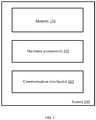
- FIG. 1 illustrates an exemplary system for detecting dynamism in a scene, according to some embodiments of the present disclosure.
- the system 100 includes one or more hardware processors 102, communication interface(s) or input/output (I/O) interface(s) 103, and one or more data storage devices or memory 101 operatively coupled to the one or more hardware processors 102.
- the one or more hardware processors 102 can be implemented as one or more microprocessors, microcomputers, microcontrollers, digital signal processors, central processing units, state machines, graphics controllers, logic circuitries, and/or any devices that manipulate signals based on operational instructions.
- the processor(s) are configured to fetch and execute computer-readable instructions stored in the memory, so as to perform one or more actions associated with the process of determining dynamism in one or more scenes.
- the system 100 can be implemented in a variety of computing systems, such as laptop computers, notebooks, hand-held devices, workstations, mainframe computers, servers, a network cloud and the like.
- the communication interface(s) 103 can include a variety of software and hardware interfaces, for example, a web interface, a graphical user interface, and the like and can facilitate multiple communications within a wide variety of networks N/W and protocol types, including wired networks, for example, LAN, cable, etc., and wireless networks, such as WLAN, cellular, or satellite.
- the communication interface(s) 103 can include one or more ports for connecting a number of devices to one another or to another server.
- the communication interface(s) 103 can be further configured to provide one or more appropriate channels having suitable communication protocols so as to facilitate data transfer between different components of the system 100, or between the system 100 and one or more other external systems.
- the memory 101 may include any computer-readable medium known in the art including, for example, volatile memory, such as static random access memory (SRAM) and dynamic random access memory (DRAM), and/or non-volatile memory, such as read only memory (ROM), erasable programmable ROM, flash memories, hard disks, optical disks, and magnetic tapes.
- volatile memory such as static random access memory (SRAM) and dynamic random access memory (DRAM)
- non-volatile memory such as read only memory (ROM), erasable programmable ROM, flash memories, hard disks, optical disks, and magnetic tapes.
- ROM read only memory
- erasable programmable ROM erasable programmable ROM
- flash memories hard disks, optical disks, and magnetic tapes.
- hard disks hard disks
- optical disks optical disks
- magnetic tapes such as magnetic tapes.
- one or more components (not shown) of the system 100 can be stored in the memory 101.
- the memory 101 is configured to store operational instructions
- the memory 101 may store input image(s) for dynamism detection and corresponding results generated, over a period of time, and may further allow user(s) having necessary permission(s) to access (and use, if needed) the stored data.
- the various steps involved in the process of determining/detecting dynamism are explained with description of FIG.2 . All the steps in FIG. 2 are explained with reference to the system of FIG. 1 .
- FIG. 2 is a flow diagram depicting steps involved in the process of detecting dynamism in the scene, using the system of FIG. 1 , according to some embodiments of the present disclosure.
- the system 100 performs the step of detecting dynamism (alternately referred to as 'dynamism detection') so as to detect/determine presence of dynamic object(s) in depth image of a particular scene (or 'Field of View (FoV)'), captured by the system 100 as input.
- the system 100 can be implemented in a variety of ways.
- the system 100 is a stand-alone system, with appropriate data capturing means attached/connected externally (for example, a depth-image sensor).
- the system 100 can be a component of a larger machine/system.
- the system 100 is a component of a robot that scans an area/location/scene for detecting presence of one or more dynamic objects, along with other related capabilities.
- the system 100 performs the dynamism detection, and corresponding data/results can be used by the robot to perform one or more actions associated with one or more applications being handled by the robot.
- the system 100 is part of a central node which is in communication with multiple other machines/systems (for example, robots). In this scenario, the system 100 may collect one or more input(s), and then performs the dynamism detection for scenes in the collected inputs, at once or in a sequential manner.
- the system 100 captures/collects/receives (202) a depth image of a scene as input, from one or more associated depth image sensors, as a reference image.
- the reference image is then processed at pixel level by the system (100), and steps 206-214 are performed at each pixel out of a plurality of pixels, and the pixel being considered and processed at any instance is referred to as a 'reference pixel'.
- the system 100 models (204) a depth sensor noise associated with the reference image as an ergodic stochastic process.
- the system 100 determines that distribution estimated at each reference pixel from a plurality of neighborhood pixels in the reference image is statistically same as a distribution estimated from evolution of the reference pixel over the time. Modeling the noise as the ergodic stochastic process results in the noise remaining fixed for each pixel, which in turn allows the system 100 to estimate the noise with respect to spatial and dynamic distribution at pixel level in the reference image.
- steps 206-214 are executed by the system 100 to perform the dynamism detection.
- the system re-projects a plurality of historical depth images for each reference pixel being considered in the reference image.
- 'historical depth images' refers to a plurality of images of the same scene, which are captured prior to capturing the reference image i.e. prior to the time instance 't'.
- the historical depth images corresponding to the reference pixel are mapped to the reference pixel, for further processing.
- the system 100 then builds (208) a spatial distribution at each pixel of the filtered reference image.
- the system 100 may use any known, suitable approach/technique for the purpose of building the spatial distribution at pixel level in the filtered reference image.
- Data being used by the system 100 for building the spatial distribution is information pertaining to the reference image collected at a time instance 't'.
- the system 100 further builds (210) a temporal distribution at each pixel of the filtered reference image.
- the system 100 may use any known, suitable approach/technique for the purpose of building the temporal distribution at pixel level in the filtered reference image.
- Data processed by the system 100 for building the temporal distribution are the re-projected historical depth images for the reference pixel being processed. This data is processed using appropriate technique so as to build the temporal distribution.
- the system 100 After determining the spatial and the temporal distributions, the system 100 then processes data pertaining to the spatial and the temporal distributions, and determines (212) divergence at each pixel of the reference image. Value of difference (or divergence) between the spatial and temporal distributions are zero, if the reference pixel corresponds to or contains data pertaining to a static object. However, if the reference pixel corresponds to a dynamic object, the value of divergence exceeds the value 'zero', and increases proportional to increase in dynamism of the object.
- the system 100 determines dynamism in the scene.
- the dynamism is determined at a single pixel level or for a group of pixels from the plurality of pixels in the reference image.
- the system 100 also determines extent of dynamism based on the value of divergence. For example, if the value of the determined divergence if small (maybe in comparison with a threshold, wherein the threshold may be pre-configured or dynamically configured with the system 100, and may be stored in appropriate database in memory 101), then the system 100 determines that the dynamism is minimal. Similarly, if the value of the determined divergence if higher in comparison with the threshold, then the system 100 determines that the dynamism is maximum, with the extent of dynamism increasing with increase in value of the divergence.
- k th reference image depth image
- I k x z k
- the pixel X H can be projected to a 3-dimensional (3D) point according to its depth I K ( x ), as in equation (2).
- ( f x ,f y ) represents focal lengths of the depth sensor used for capturing the reference image, along x and y directions respectively
- ( c x ,c y ) represents principle points along respective directions.
- x H ⁇ K j T i P i x
- K [ f x 0 c x ; 0 f y c y ; 0 0 1] is camera internal matrix. So equation (4) can be used to build a new depth image.
- the system 100 has Î a set of N predicted depth frames at time frame j.
- samples from temporal re-projected depth images at location x and samples collected spatially at a current original depth map at the same location are generated from the same probabilistic function, had it been from a static background. If the two generated sample sets are from different probabilistic distributions, it implies that the current depth value at location x is coming from a dynamic background.
- BaMVO defines a random variable with difference in between a wrapped depth image and original depth image, as shown below:
- BaMVO requires only the parameter 'k (number of previous frames)' to be provided by a user.
- the method and system disclosed herein also requires 'k' as a user input to the system 100.
- quality of result increases with increase in number of frames considered, in BaMVO as well as in the method and system disclosed herein.
- the results indicated that noise in comparison is very less in results of the method and system disclosed herein.
- results generated by the system 100 also distinguishes parts of result in terms of extent of dynamism detected. This is depicted in FIGS. 3A and 3B , wherein 3B depicts result obtained with BaMVO and 3A depicts result obtained with the system 100.
- the embodiments of present disclosure herein addresses unresolved problem of dynamism detection in a scene, by processing depth images.
- the embodiment thus provides a mechanism for modelling depth sensor noise in the depth image.
- the embodiments herein further provides a mechanism for building spatial and temporal distributions based on the modelling of the depth sensor noise, which in turn used to determine dynamism in the scene.
- the hardware device can be any kind of device which can be programmed including e.g. any kind of computer like a server or a personal computer, or the like, or any combination thereof.
- the device may also include means which could be e.g. hardware means like e.g. an application-specific integrated circuit (ASIC), a field-programmable gate array (FPGA), or a combination of hardware and software means, e.g.
- ASIC application-specific integrated circuit
- FPGA field-programmable gate array
- the means can include both hardware means and software means.
- the method embodiments described herein could be implemented in hardware and software.
- the device may also include software means.
- the embodiments may be implemented on different hardware devices, e.g. using a plurality of CPUs.
- the embodiments herein can comprise hardware and software elements.
- the embodiments that are implemented in software include but are not limited to, firmware, resident software, microcode, etc.
- the functions performed by various components described herein may be implemented in other components or combinations of other components.
- a computer-usable or computer readable medium can be any apparatus that can comprise, store, communicate, propagate, or transport the program for use by or in connection with the instruction execution system, apparatus, or device.
- a computer-readable storage medium refers to any type of physical memory on which information or data readable by a processor may be stored.
- a computer-readable storage medium may store instructions for execution by one or more processors, including instructions for causing the processor(s) to perform steps or stages consistent with the embodiments described herein.
- the term "computer-readable medium” should be understood to include tangible items and exclude carrier waves and transient signals, i.e., be non-transitory. Examples include random access memory (RAM), read-only memory (ROM), volatile memory, nonvolatile memory, hard drives, CD ROMs, DVDs, flash drives, disks, and any other known physical storage media.
Landscapes
- Engineering & Computer Science (AREA)
- Physics & Mathematics (AREA)
- General Physics & Mathematics (AREA)
- Theoretical Computer Science (AREA)
- Computer Vision & Pattern Recognition (AREA)
- Multimedia (AREA)
- Image Analysis (AREA)
Abstract
Description
- The present application claims priority from Indian complete patent application no.
201921039592, filed on September 30, 2019 - The disclosure herein generally relates to image processing, and, more particularly, to a method and system for determining dynamism in a scene by processing depth image of the scene, captured from a moving camera.
- Detecting dynamism in a scene refers to detecting dynamic movement of one or more objects in the scene. The dynamism detection finds its application in a variety of fields such as but not limited to robotics and augmented/virtual reality. In robotics, in various circumstances a robot may have to detect presence or absence of objects in own field of view. In augmented reality (AR) based systems, users are allowed to interact with the system in real-time and the system takes/triggers certain actions in response. For example, the AR based gaming systems detect user movements and accordingly perform corresponding actions.
- In all these examples, the system needs to detect dynamic changes in a field of view of a moving image sensor which is part of the system. However, like in any other image processing techniques, state of art systems in the domain of dynamism detection also face challenges due to presence of noise in the scene. Especially when images captured are depth images, noise level is dependent on the scenes, and each pixel in the image may represent different characteristics of the noise. As a result, it is difficult to model the noise beforehand if the system is capturing depth images as input, which in turn may result in the system interpreting the noise contents as dynamic objects, which in turn affects accuracy of the dynamism detection being performed.
- Embodiments of the present disclosure present technological improvements as solutions to one or more of the above-mentioned technical problems recognized by the inventors in conventional systems. For example, in one embodiment, a processor implemented method for determining dynamism is provided. In this process, a depth image of a scene at time instance 't' is collected as a reference image, via one or more hardware processors, wherein a depth sensor noise associated with the collected reference image is modelled as an ergodic stochastic process. Modelling the depth sensor noise as the ergodic stochastic process comprises determining that distribution estimated at each reference pixel from a plurality of neighborhood pixels is statistically same as a distribution estimated from evolution of the reference pixel over the time. Further, a plurality of historical depth images are re-projected onto the current time 't' via one or more hardware processors. Then a spatial distribution is built at each of a plurality of pixels of the reference image, by processing the reference image via the one or more hardware processors. Further, a temporal distribution is built at each of a plurality of pixels of the filtered reference image, by processing the re-projected historical depth images corresponding to the filtered reference image via the one or more hardware processors. Further, divergence at each of the plurality of pixels of the reference image is determined, based on the spatial distribution and the temporal distribution, via the one or more hardware processors. Further, dynamism in the scene is determined based on the determined divergence in at least a few of the plurality of pixels, via the one or more hardware processors.
- In another aspect, a system for determining dynamism is provided. The system comprises one or more hardware processors, one or more communication interfaces, and one or more memory storing a plurality of instructions. The plurality of instructions when executed cause the one or more hardware processors to collect a depth image of a scene at time instance 't' as a reference image, via one or more hardware processors, wherein a depth sensor noise associated with the collected reference image is modelled as an ergodic stochastic process. The system models the depth sensor noise as the ergodic stochastic process by determining that distribution estimated at each reference pixel from a plurality of neighborhood pixels is statistically same as a distribution estimated from evolution of the reference pixel over the time. Further, a plurality of historical depth images are re-projected onto the current time 't' via one or more hardware processors. The system then builds a spatial distribution at each of a plurality of pixels of the reference image, by processing the reference image via the one or more hardware processors. The system further builds a temporal distribution at each of a plurality of pixels of the filtered reference image, by processing the re-projected historical depth images via the one or more hardware processors. Further, the system determines divergence at each of the plurality of pixels of the reference image based on the spatial distribution and the temporal distribution, via the one or more hardware processors. Further, the system determines dynamism in the scene based on the determined divergence in at least a few of the plurality of pixels, via the one or more hardware processors.
- In yet another aspect, a non-transitory computer readable medium for determining dynamism is provided. The non-transitory computer readable medium comprises program codes which when executed cause the non-transitory computer readable medium to determine dynamism in a scene, by executing steps in the following method. In this process, a depth image of a scene at time instance 't' is collected as a reference image, via one or more hardware processors, wherein a depth sensor noise associated with the collected reference image is modelled as an ergodic stochastic process. Modelling the depth sensor noise as the ergodic stochastic process comprises determining that distribution estimated at each reference pixel from a plurality of neighborhood pixels is statistically same as a distribution estimated from evolution of the reference pixel over the time. Further, a plurality of historical depth images corresponding to each reference pixel being considered in the reference image are re-projected to the time instance 't', via the one or more hardware processors. Then a spatial distribution is built at each of a plurality of pixels of the filtered reference image, by processing the filtered reference image via the one or more hardware processors. Further, a temporal distribution is built at each of a plurality of pixels of the filtered reference image, by processing the re-projected historical depth images via the one or more hardware processors. Further, divergence at each of the plurality of pixels of the filtered reference image is determined, based on the spatial distribution and the temporal distribution, via the one or more hardware processors. Further, dynamism in the scene is determined based on the determined divergence in at least a few of the plurality of pixels, via the one or more hardware processors.
- It is to be understood that both the foregoing general description and the following detailed description are exemplary and explanatory only and are not restrictive of the invention, as claimed.
- The accompanying drawings, which are incorporated in and constitute a part of this disclosure, illustrate exemplary embodiments and, together with the description, serve to explain the disclosed principles:
-
FIG. 1 illustrates an exemplary system for detecting dynamism in a scene, according to some embodiments of the present disclosure. -
FIG. 2 is a flow diagram depicting steps involved in the process of detecting dynamism in a scene, using the system ofFIG. 1 , according to some embodiments of the present disclosure. -
FIGS. 3A through 3C illustrate example results of dynamism detection performed by a state of art technique and the method and system disclosed herein, in accordance with some embodiments of the present disclosure. - Exemplary embodiments are described with reference to the accompanying drawings. In the figures, the left-most digit(s) of a reference number identifies the figure in which the reference number first appears. Wherever convenient, the same reference numbers are used throughout the drawings to refer to the same or like parts. While examples and features of disclosed principles are described herein, modifications, adaptations, and other implementations are possible without departing from the scope of the disclosed embodiments. It is intended that the following detailed description be considered as exemplary only, with the true scope being indicated by the following claims.
- Referring now to the drawings, and more particularly to
FIG. 1 through FIG. 3C , where similar reference characters denote corresponding features consistently throughout the figures, there are shown preferred embodiments and these embodiments are described in the context of the following exemplary system and/or method. -
FIG. 1 illustrates an exemplary system for detecting dynamism in a scene, according to some embodiments of the present disclosure. Thesystem 100 includes one ormore hardware processors 102, communication interface(s) or input/output (I/O) interface(s) 103, and one or more data storage devices ormemory 101 operatively coupled to the one ormore hardware processors 102. The one ormore hardware processors 102 can be implemented as one or more microprocessors, microcomputers, microcontrollers, digital signal processors, central processing units, state machines, graphics controllers, logic circuitries, and/or any devices that manipulate signals based on operational instructions. Among other capabilities, the processor(s) are configured to fetch and execute computer-readable instructions stored in the memory, so as to perform one or more actions associated with the process of determining dynamism in one or more scenes. In an embodiment, thesystem 100 can be implemented in a variety of computing systems, such as laptop computers, notebooks, hand-held devices, workstations, mainframe computers, servers, a network cloud and the like. - The communication interface(s) 103 can include a variety of software and hardware interfaces, for example, a web interface, a graphical user interface, and the like and can facilitate multiple communications within a wide variety of networks N/W and protocol types, including wired networks, for example, LAN, cable, etc., and wireless networks, such as WLAN, cellular, or satellite. In an embodiment, the communication interface(s) 103 can include one or more ports for connecting a number of devices to one another or to another server. The communication interface(s) 103 can be further configured to provide one or more appropriate channels having suitable communication protocols so as to facilitate data transfer between different components of the
system 100, or between thesystem 100 and one or more other external systems. - The
memory 101 may include any computer-readable medium known in the art including, for example, volatile memory, such as static random access memory (SRAM) and dynamic random access memory (DRAM), and/or non-volatile memory, such as read only memory (ROM), erasable programmable ROM, flash memories, hard disks, optical disks, and magnetic tapes. In an embodiment, one or more components (not shown) of thesystem 100 can be stored in thememory 101. Thememory 101 is configured to store operational instructions/program codes which when executed cause one or more of the hardware processor(s) 102 to perform various actions associated with the dynamism detection being handled by thesystem 100. Thememory 101 can be configured to store all or selected data associated with the process of detecting dynamism in the scenes(s). For example, thememory 101 may store input image(s) for dynamism detection and corresponding results generated, over a period of time, and may further allow user(s) having necessary permission(s) to access (and use, if needed) the stored data. The various steps involved in the process of determining/detecting dynamism are explained with description ofFIG.2 . All the steps inFIG. 2 are explained with reference to the system ofFIG. 1 . -
FIG. 2 is a flow diagram depicting steps involved in the process of detecting dynamism in the scene, using the system ofFIG. 1 , according to some embodiments of the present disclosure. Thesystem 100 performs the step of detecting dynamism (alternately referred to as 'dynamism detection') so as to detect/determine presence of dynamic object(s) in depth image of a particular scene (or 'Field of View (FoV)'), captured by thesystem 100 as input. Thesystem 100 can be implemented in a variety of ways. In an embodiment, thesystem 100 is a stand-alone system, with appropriate data capturing means attached/connected externally (for example, a depth-image sensor). In another embodiment, thesystem 100 can be a component of a larger machine/system. For example, thesystem 100 is a component of a robot that scans an area/location/scene for detecting presence of one or more dynamic objects, along with other related capabilities. In this example, thesystem 100 performs the dynamism detection, and corresponding data/results can be used by the robot to perform one or more actions associated with one or more applications being handled by the robot. In another embodiment, thesystem 100 is part of a central node which is in communication with multiple other machines/systems (for example, robots). In this scenario, thesystem 100 may collect one or more input(s), and then performs the dynamism detection for scenes in the collected inputs, at once or in a sequential manner. - The
system 100 captures/collects/receives (202) a depth image of a scene as input, from one or more associated depth image sensors, as a reference image. The reference image is then processed at pixel level by the system (100), and steps 206-214 are performed at each pixel out of a plurality of pixels, and the pixel being considered and processed at any instance is referred to as a 'reference pixel'. - Further, for the captured reference image, the
system 100 models (204) a depth sensor noise associated with the reference image as an ergodic stochastic process. At this step, thesystem 100 determines that distribution estimated at each reference pixel from a plurality of neighborhood pixels in the reference image is statistically same as a distribution estimated from evolution of the reference pixel over the time. Modeling the noise as the ergodic stochastic process results in the noise remaining fixed for each pixel, which in turn allows thesystem 100 to estimate the noise with respect to spatial and dynamic distribution at pixel level in the reference image. After modeling the depth sensor noise as the ergodic stochastic process, steps 206-214 are executed by thesystem 100 to perform the dynamism detection. - At
step 206, the system re-projects a plurality of historical depth images for each reference pixel being considered in the reference image. Here the term 'historical depth images' refers to a plurality of images of the same scene, which are captured prior to capturing the reference image i.e. prior to the time instance 't'. By re-projecting, the historical depth images corresponding to the reference pixel are mapped to the reference pixel, for further processing. - The
system 100 then builds (208) a spatial distribution at each pixel of the filtered reference image. In an embodiment, thesystem 100 may use any known, suitable approach/technique for the purpose of building the spatial distribution at pixel level in the filtered reference image. Data being used by thesystem 100 for building the spatial distribution is information pertaining to the reference image collected at a time instance 't'. Thesystem 100 further builds (210) a temporal distribution at each pixel of the filtered reference image. In an embodiment, thesystem 100 may use any known, suitable approach/technique for the purpose of building the temporal distribution at pixel level in the filtered reference image. Data processed by thesystem 100 for building the temporal distribution are the re-projected historical depth images for the reference pixel being processed. This data is processed using appropriate technique so as to build the temporal distribution. - After determining the spatial and the temporal distributions, the
system 100 then processes data pertaining to the spatial and the temporal distributions, and determines (212) divergence at each pixel of the reference image. Value of difference (or divergence) between the spatial and temporal distributions are zero, if the reference pixel corresponds to or contains data pertaining to a static object. However, if the reference pixel corresponds to a dynamic object, the value of divergence exceeds the value 'zero', and increases proportional to increase in dynamism of the object. - Further, based on the determined value of the divergence, the
system 100 determines dynamism in the scene. In various embodiments, the dynamism is determined at a single pixel level or for a group of pixels from the plurality of pixels in the reference image. In addition to determining presence or absence of dynamism, thesystem 100 also determines extent of dynamism based on the value of divergence. For example, if the value of the determined divergence if small (maybe in comparison with a threshold, wherein the threshold may be pre-configured or dynamically configured with thesystem 100, and may be stored in appropriate database in memory 101), then thesystem 100 determines that the dynamism is minimal. Similarly, if the value of the determined divergence if higher in comparison with the threshold, then thesystem 100 determines that the dynamism is maximum, with the extent of dynamism increasing with increase in value of the divergence. - The steps in
method 200 are explained from a mathematical perspective below: - Let kth reference image (depth image) be represented as:

x = {x, y} T ∈ Ω denotes pixel coordinates. - In Homogeneous coordinate systems, the reference pixel is written as XH = {x,y,1} T . The pixel XH can be projected to a 3-dimensional (3D) point according to its depth IK (x), as in equation (2).

- Given a series of N depth frames, IK , for k = 1, 2, ... N, and transformation matrices kT
w = [kRw , ktw ; 0 1] of the frames with respect to a global coordinate system (W), transform between two frames k = i and k = j can be computed as:
- Now the re-projection of historical depth images can be done as below:
- Re-projection of points (such as x) from ith frame to jth frame, according to corresponding depth value Ii (x) = zi can be done as in equation (4).

system 100 has Î a set of N predicted depth frames at time frame j. - Two probabilistic models are used by the
system 100, one for Î(x) and one for IN (x). Another assumption made is that both the probabilistic structures being considered are Gaussian, however, any nonparametric probabilistic structure can be used. Samples considered to estimate the probability structures are given as:
 defines a neighborhood system of order o, given as:

- According to the ergodic assumption made by the
system 100, samples from temporal re-projected depth images at location x and samples collected spatially at a current original depth map at the same location are generated from the same probabilistic function, had it been from a static background. If the two generated sample sets are from different probabilistic distributions, it implies that the current depth value at location x is coming from a dynamic background. The fields are defined for the spatial and temporal sample sets as:


- In order to perform the dynamism estimation, initially the fields Mt , Ms , Vt , Vs are smoothed with a Gaussian filter, so as to remove any noise that may be present. Metric for estimating the dynamism is defined as:

- If two distributions are uni-variate Gaussian, the divergence between the two distributions can be rewritten as:


- For the purpose of experimentation, data from an open database "TUM-RGBD" was considered, apart from data internally created. The data considered had a UAV flying in front of a depth sensor used. Performance of the dynamism detection methodology disclosed herein was compared with a state of art technique "BaMVO". BaMVO defines a random variable with difference in between a wrapped depth image and original depth image, as shown below:

- BaMVO requires only the parameter 'k (number of previous frames)' to be provided by a user. The method and system disclosed herein also requires 'k' as a user input to the
system 100. Experiments proved that quality of result increases with increase in number of frames considered, in BaMVO as well as in the method and system disclosed herein. However, the results indicated that noise in comparison is very less in results of the method and system disclosed herein. In addition to this, results generated by thesystem 100 also distinguishes parts of result in terms of extent of dynamism detected. This is depicted inFIGS. 3A and3B , wherein 3B depicts result obtained with BaMVO and 3A depicts result obtained with thesystem 100. In 3A, more dynamic areas are represented by darker areas and less dynamic areas are represented by lighter areas. As can be seen in 3B, BaMVO tends to detect depth boundaries also as dynamic, which in turn results in less accuracy. When experiments were conducted based on data in which the dynamic object is occluded by static objects, results obtained bysystem 100 contained less noise in comparison with the result produced by BaMVO. Other scenarios tried during experimentation are with the depth sensor rotating abruptly and size of the dynamic objects being small. In both the scenarios, the method and system disclosed herein appear to be giving better results than BaMVO in terms of accuracy of the dynamism detection performed. BaMVO in certain conditions even failed to detect the dynamic object having smaller size. Examples inFIG. 3C depict that BaMVO tends to detect/interpret depth discontinuity also as dynamic, whereas thesystem 100 detects only the dynamic object and not the depth discontinuity as dynamic. - The written description describes the subject matter herein to enable any person skilled in the art to make and use the embodiments. The scope of the subject matter embodiments is defined by the claims and may include other modifications that occur to those skilled in the art. Such other modifications are intended to be within the scope of the claims if they have similar elements that do not differ from the literal language of the claims or if they include equivalent elements with insubstantial differences from the literal language of the claims.
- The embodiments of present disclosure herein addresses unresolved problem of dynamism detection in a scene, by processing depth images. The embodiment, thus provides a mechanism for modelling depth sensor noise in the depth image. Moreover, the embodiments herein further provides a mechanism for building spatial and temporal distributions based on the modelling of the depth sensor noise, which in turn used to determine dynamism in the scene.
- It is to be understood that the scope of the protection is extended to such a program and in addition to a computer-readable means having a message therein; such computer-readable storage means contain program-code means for implementation of one or more steps of the method, when the program runs on a server or mobile device or any suitable programmable device. The hardware device can be any kind of device which can be programmed including e.g. any kind of computer like a server or a personal computer, or the like, or any combination thereof. The device may also include means which could be e.g. hardware means like e.g. an application-specific integrated circuit (ASIC), a field-programmable gate array (FPGA), or a combination of hardware and software means, e.g. an ASIC and an FPGA, or at least one microprocessor and at least one memory with software processing components located therein. Thus, the means can include both hardware means and software means. The method embodiments described herein could be implemented in hardware and software. The device may also include software means. Alternatively, the embodiments may be implemented on different hardware devices, e.g. using a plurality of CPUs.
- The embodiments herein can comprise hardware and software elements. The embodiments that are implemented in software include but are not limited to, firmware, resident software, microcode, etc. The functions performed by various components described herein may be implemented in other components or combinations of other components. For the purposes of this description, a computer-usable or computer readable medium can be any apparatus that can comprise, store, communicate, propagate, or transport the program for use by or in connection with the instruction execution system, apparatus, or device.
- The illustrated steps are set out to explain the exemplary embodiments shown, and it should be anticipated that ongoing technological development will change the manner in which particular functions are performed. These examples are presented herein for purposes of illustration, and not limitation. Further, the boundaries of the functional building blocks have been arbitrarily defined herein for the convenience of the description. Alternative boundaries can be defined so long as the specified functions and relationships thereof are appropriately performed. Alternatives (including equivalents, extensions, variations, deviations, etc., of those described herein) will be apparent to persons skilled in the relevant art(s) based on the teachings contained herein. Such alternatives fall within the scope of the disclosed embodiments. Also, the words "comprising," "having," "containing," and "including," and other similar forms are intended to be equivalent in meaning and be open ended in that an item or items following any one of these words is not meant to be an exhaustive listing of such item or items, or meant to be limited to only the listed item or items. It must also be noted that as used herein and in the appended claims, the singular forms "a," "an," and "the" include plural references unless the context clearly dictates otherwise.
- Furthermore, one or more computer-readable storage media may be utilized in implementing embodiments consistent with the present disclosure. A computer-readable storage medium refers to any type of physical memory on which information or data readable by a processor may be stored. Thus, a computer-readable storage medium may store instructions for execution by one or more processors, including instructions for causing the processor(s) to perform steps or stages consistent with the embodiments described herein. The term "computer-readable medium" should be understood to include tangible items and exclude carrier waves and transient signals, i.e., be non-transitory. Examples include random access memory (RAM), read-only memory (ROM), volatile memory, nonvolatile memory, hard drives, CD ROMs, DVDs, flash drives, disks, and any other known physical storage media.
- It is intended that the disclosure and examples be considered as exemplary only, with a true scope of disclosed embodiments being indicated by the following claims.
Claims (15)
- A processor implemented method (200) for determining dynamism, comprising:collecting (202) a depth image of a scene at time instance 't' as a reference image, via one or more hardware processors, wherein a depth sensor noise associated with the collected reference image is modelled as an ergodic stochastic process;re-projecting (206) a plurality of historical depth images onto the time instance 't', via one or more hardware processors;building (208) a spatial distribution at each of a plurality of pixels of the reference image, by processing the filtered reference image via the one or more hardware processors;building (210) a temporal distribution at each of the plurality of pixels of the reference image, by processing the plurality of re-projected historical depth images via the one or more hardware processors;determining (212) divergence at each of the plurality of pixels of the reference image, based on the spatial distribution and the temporal distribution, via the one or more hardware processors; anddetermining (214) dynamism in the scene, based on the determined divergence in one or more of the plurality of the pixels, via the one or more hardware processors.
- The method as claimed in claim 1, wherein the plurality of historical images are images of the same scene taken prior to the time instance 't'.
- The method as claimed in claim 1, wherein modelling the depth sensor noise as the ergodic stochastic process comprises determining that distribution estimated at each reference pixel from a plurality of neighborhood pixels is statistically same as a distribution estimated from evolution of the reference pixel over the time.
- The method as claimed in claim 3, wherein the evolution of the reference pixel is the change of a pixel at the reference image, measured from the re-projected historical depth images at the same pixel.
- The method as claimed in claim 1, wherein determining the dynamism in the scene based on the determined divergence comprises:determining that object in the at least few of the plurality of pixels is a static object if value of determined divergence for the at least few of the plurality of pixels is zero; anddetermining that object in the at least few of the plurality of pixels is a dynamic object if value of determined divergence for the at least few of the plurality of pixels is a value exceeding zero.
- The method as claimed in claim 1, wherein extent of dynamism is determined based on value of the determined divergence between the spatial distribution and the temporal distribution.
- A system (100) for determining dynamism, comprising:one or more hardware processors (102);one or more communication interfaces (103); andone or more memory (101) storing a plurality of instructions, wherein the plurality of instructions when executed cause the one or more hardware processors (102) to:collect (202) a depth image of a scene at time instance 't' as a reference image, via one or more hardware processors, wherein a depth sensor noise associated with the collected reference image is modelled as an ergodic stochastic process;re-project (206) a plurality of historical depth images onto the time instance 't', via one or more hardware processors;build (208) a spatial distribution at each of a plurality of pixels of the reference image, by processing the reference image via the one or more hardware processors;build (210) a temporal distribution at each of the plurality of pixels of the reference image, by processing the plurality of re-projected historical depth images via the one or more hardware processors;determine (212) divergence at each of the plurality of pixels of the reference image, based on the spatial distribution and the temporal distribution, via the one or more hardware processors; anddetermine (214) dynamism in the scene, based on the determined divergence in one or more of the pixels, via the one or more hardware processors.
- The system (100) as claimed in claim 7, wherein the plurality of historical images are images of the same scene taken prior to the time instance 't'.
- The system (100) as claimed in claim 7, wherein the system is configured to model the depth sensor noise as the ergodic stochastic process by determining that distribution estimated at each reference pixel from a plurality of neighborhood pixels is statistically same as a distribution estimated from evolution of the reference pixel over the time.
- The system (100) as claimed in claim 9, wherein the evolution of the reference pixel is the change of a pixel at the reference image, measured from the re-projected historical depth images at the same pixel.
- The system (100) as claimed in claim 7, wherein the system determines the dynamism in the scene based on the determined divergence by:determining that object in the at least few of the plurality of pixels is a static object if value of determined divergence for the at least few of the plurality of pixels is zero; anddetermining that object in the at least few of the plurality of pixels is a dynamic object if value of determined divergence for the at least few of the plurality of pixels is a value exceeding zero.
- The system (100) as claimed in claim 7, wherein the system determines an extent of dynamism based on value of the determined divergence between the spatial distribution and the temporal distribution.
- A non-transitory computer readable medium for determining dynamism, the non-transitory computer readable medium comprising a plurality of instructions which when executed cause one or more hardware processors to:collect a depth image of a scene at time instance 't' as a reference image, wherein a depth sensor noise associated with the collected reference image is modelled as an ergodic stochastic process;re-project a plurality of historical depth images onto the time instance 't';build a spatial distribution at each of a plurality of pixels of the reference image, by processing the filtered reference image;build a temporal distribution at each of the plurality of pixels of the reference image, by processing the plurality of re-projected historical depth images;determine divergence at each of the plurality of pixels of the reference image, based on the spatial distribution and the temporal distribution; anddetermine dynamism in the scene, based on the determined divergence in one or more of the plurality of the pixels.
- The non-transitory computer readable medium as claimed in claim 13, wherein modelling the depth sensor noise as the ergodic stochastic process comprises determining that distribution estimated at each reference pixel from a plurality of neighborhood pixels is statistically same as a distribution estimated from evolution of the reference pixel over the time.
- The non-transitory computer readable medium as claimed in claim 13, wherein determining the dynamism in the scene based on the determined divergence comprises:determining that object in the at least few of the plurality of pixels is a static object if value of determined divergence for the at least few of the plurality of pixels is zero; anddetermining that object in the at least few of the plurality of pixels is a dynamic object if value of determined divergence for the at least few of the plurality of pixels is a value exceeding zero.
Applications Claiming Priority (1)
| Application Number | Priority Date | Filing Date | Title |
|---|---|---|---|
| IN201921039592 | 2019-09-30 |
Publications (3)
| Publication Number | Publication Date |
|---|---|
| EP3798976A1 true EP3798976A1 (en) | 2021-03-31 |
| EP3798976C0 EP3798976C0 (en) | 2023-11-01 |
| EP3798976B1 EP3798976B1 (en) | 2023-11-01 |
Family
ID=72659759
Family Applications (1)
| Application Number | Title | Priority Date | Filing Date |
|---|---|---|---|
| EP20198607.2A Active EP3798976B1 (en) | 2019-09-30 | 2020-09-28 | Method and system for determining dynamism in a scene by processing a depth image |
Country Status (2)
| Country | Link |
|---|---|
| US (1) | US11443446B2 (en) |
| EP (1) | EP3798976B1 (en) |
Citations (1)
| Publication number | Priority date | Publication date | Assignee | Title |
|---|---|---|---|---|
| US8073196B2 (en) * | 2006-10-16 | 2011-12-06 | University Of Southern California | Detection and tracking of moving objects from a moving platform in presence of strong parallax |
Family Cites Families (7)
| Publication number | Priority date | Publication date | Assignee | Title |
|---|---|---|---|---|
| US20140009462A1 (en) * | 2012-04-17 | 2014-01-09 | 3Dmedia Corporation | Systems and methods for improving overall quality of three-dimensional content by altering parallax budget or compensating for moving objects |
| CN103325112B (en) | 2013-06-07 | 2016-03-23 | 中国民航大学 | Moving target method for quick in dynamic scene |
| CN104424649B (en) * | 2013-08-21 | 2017-09-26 | 株式会社理光 | Detect the method and system of moving object |
| CN104794733B (en) * | 2014-01-20 | 2018-05-08 | 株式会社理光 | Method for tracing object and device |
| JP6030617B2 (en) * | 2014-10-15 | 2016-11-24 | 株式会社ソニー・インタラクティブエンタテインメント | Image processing apparatus and image processing method |
| EP3376760A4 (en) * | 2015-11-11 | 2019-04-03 | Sony Corporation | Image processing device and image processing method |
| US11190746B2 (en) * | 2018-12-21 | 2021-11-30 | Google Llc | Real-time spacetime stereo using spacetime descriptors |
-
2020
- 2020-09-28 EP EP20198607.2A patent/EP3798976B1/en active Active
- 2020-09-29 US US17/036,213 patent/US11443446B2/en active Active
Patent Citations (1)
| Publication number | Priority date | Publication date | Assignee | Title |
|---|---|---|---|---|
| US8073196B2 (en) * | 2006-10-16 | 2011-12-06 | University Of Southern California | Detection and tracking of moving objects from a moving platform in presence of strong parallax |
Non-Patent Citations (2)
| Title |
|---|
| P-M JODOIN ET AL: "Statistical Background Subtraction Using Spatial Cues", IEEE TRANSACTIONS ON CIRCUITS AND SYSTEMS FOR VIDEO TECHNOLOGY, INSTITUTE OF ELECTRICAL AND ELECTRONICS ENGINEERS, US, vol. 17, no. 12, 1 December 2007 (2007-12-01), pages 1758 - 1763, XP011195155, ISSN: 1051-8215, DOI: 10.1109/TCSVT.2007.906935 * |
| YADAV DILEEP KUMAR ET AL: "A combined approach of Kullback-Leibler divergence and background subtraction for moving object detection in thermal video", INFRARED PHYSICS AND TECHNOLOGY, ELSEVIER SCIENCE, GB, vol. 76, 4 February 2016 (2016-02-04), pages 21 - 31, XP029540115, ISSN: 1350-4495, DOI: 10.1016/J.INFRARED.2015.12.027 * |
Also Published As
| Publication number | Publication date |
|---|---|
| EP3798976C0 (en) | 2023-11-01 |
| EP3798976B1 (en) | 2023-11-01 |
| US20210097706A1 (en) | 2021-04-01 |
| US11443446B2 (en) | 2022-09-13 |
Similar Documents
| Publication | Publication Date | Title |
|---|---|---|
| Abid Hasan et al. | Depth edge detection by image-based smoothing and morphological operations | |
| EP3201881B1 (en) | 3-dimensional model generation using edges | |
| JP7078139B2 (en) | Video stabilization methods and equipment, as well as non-temporary computer-readable media | |
| CN108876813B (en) | Image processing method, device and equipment for detecting object in video | |
| EP3762899B1 (en) | Object segmentation in a sequence of color image frames based on adaptive foreground mask upsampling | |
| US11544348B2 (en) | Neural network based position estimation of target object of interest in video frames | |
| US11756224B2 (en) | Circle center detection in imagery | |
| EP2960859B1 (en) | Constructing a 3d structure | |
| CN112348828A (en) | Example segmentation method and device based on neural network and storage medium | |
| EP3648013A1 (en) | Method and system for partitioning of deep convolution network for executing on computationally constraint devices | |
| CN111598088B (en) | Target detection method, device, computer equipment and readable storage medium | |
| US20140369622A1 (en) | Image completion based on patch offset statistics | |
| CN113112542A (en) | Visual positioning method and device, electronic equipment and storage medium | |
| CN115393815A (en) | Road information generation method and device, electronic equipment and computer readable medium | |
| CN113657518B (en) | Training method, target image detection method, device, electronic device, and medium | |
| US11361548B2 (en) | Method and system for multi instance visual tracking based on observer motion modelling | |
| EP3798976A1 (en) | Method and system for determining dynamism in a scene by processing a depth image | |
| CN112819889A (en) | Method and device for determining position information, storage medium and electronic device | |
| CN111507999B (en) | Target tracking method and device based on FDSST algorithm | |
| Russo et al. | Blurring prediction in monocular slam | |
| CN111079643B (en) | Face detection method and device based on neural network and electronic equipment | |
| CN110443244B (en) | Graphics processing method and related device | |
| US11080540B2 (en) | 3D vision processing using an IP block | |
| CN109150993B (en) | Method for obtaining network request tangent plane, terminal device and storage medium | |
| CN110545373B (en) | Spatial environment sensing method and device |
Legal Events
| Date | Code | Title | Description |
|---|---|---|---|
| PUAI | Public reference made under article 153(3) epc to a published international application that has entered the european phase |
Free format text: ORIGINAL CODE: 0009012 |
|
| STAA | Information on the status of an ep patent application or granted ep patent |
Free format text: STATUS: THE APPLICATION HAS BEEN PUBLISHED |
|
| AK | Designated contracting states |
Kind code of ref document: A1 Designated state(s): AL AT BE BG CH CY CZ DE DK EE ES FI FR GB GR HR HU IE IS IT LI LT LU LV MC MK MT NL NO PL PT RO RS SE SI SK SM TR |
|
| AX | Request for extension of the european patent |
Extension state: BA ME |
|
| STAA | Information on the status of an ep patent application or granted ep patent |
Free format text: STATUS: REQUEST FOR EXAMINATION WAS MADE |
|
| 17P | Request for examination filed |
Effective date: 20210930 |
|
| RBV | Designated contracting states (corrected) |
Designated state(s): AL AT BE BG CH CY CZ DE DK EE ES FI FR GB GR HR HU IE IS IT LI LT LU LV MC MK MT NL NO PL PT RO RS SE SI SK SM TR |
|
| GRAP | Despatch of communication of intention to grant a patent |
Free format text: ORIGINAL CODE: EPIDOSNIGR1 |
|
| STAA | Information on the status of an ep patent application or granted ep patent |
Free format text: STATUS: GRANT OF PATENT IS INTENDED |
|
| INTG | Intention to grant announced |
Effective date: 20230426 |
|
| GRAS | Grant fee paid |
Free format text: ORIGINAL CODE: EPIDOSNIGR3 |
|
| GRAA | (expected) grant |
Free format text: ORIGINAL CODE: 0009210 |
|
| STAA | Information on the status of an ep patent application or granted ep patent |
Free format text: STATUS: THE PATENT HAS BEEN GRANTED |
|
| AK | Designated contracting states |
Kind code of ref document: B1 Designated state(s): AL AT BE BG CH CY CZ DE DK EE ES FI FR GB GR HR HU IE IS IT LI LT LU LV MC MK MT NL NO PL PT RO RS SE SI SK SM TR |
|
| REG | Reference to a national code |
Ref country code: GB Ref legal event code: FG4D |
|
| REG | Reference to a national code |
Ref country code: CH Ref legal event code: EP |
|
| REG | Reference to a national code |
Ref country code: DE Ref legal event code: R096 Ref document number: 602020020161 Country of ref document: DE |
|
| REG | Reference to a national code |
Ref country code: IE Ref legal event code: FG4D |
|
| U01 | Request for unitary effect filed |
Effective date: 20231101 |
|
| U07 | Unitary effect registered |
Designated state(s): AT BE BG DE DK EE FI FR IT LT LU LV MT NL PT SE SI Effective date: 20231106 |
|
| PG25 | Lapsed in a contracting state [announced via postgrant information from national office to epo] |
Ref country code: GR Free format text: LAPSE BECAUSE OF FAILURE TO SUBMIT A TRANSLATION OF THE DESCRIPTION OR TO PAY THE FEE WITHIN THE PRESCRIBED TIME-LIMIT Effective date: 20240202 |
|
| PG25 | Lapsed in a contracting state [announced via postgrant information from national office to epo] |
Ref country code: IS Free format text: LAPSE BECAUSE OF FAILURE TO SUBMIT A TRANSLATION OF THE DESCRIPTION OR TO PAY THE FEE WITHIN THE PRESCRIBED TIME-LIMIT Effective date: 20240301 |
|
| PG25 | Lapsed in a contracting state [announced via postgrant information from national office to epo] |
Ref country code: ES Free format text: LAPSE BECAUSE OF FAILURE TO SUBMIT A TRANSLATION OF THE DESCRIPTION OR TO PAY THE FEE WITHIN THE PRESCRIBED TIME-LIMIT Effective date: 20231101 |
|
| PG25 | Lapsed in a contracting state [announced via postgrant information from national office to epo] |
Ref country code: IS Free format text: LAPSE BECAUSE OF FAILURE TO SUBMIT A TRANSLATION OF THE DESCRIPTION OR TO PAY THE FEE WITHIN THE PRESCRIBED TIME-LIMIT Effective date: 20240301 Ref country code: GR Free format text: LAPSE BECAUSE OF FAILURE TO SUBMIT A TRANSLATION OF THE DESCRIPTION OR TO PAY THE FEE WITHIN THE PRESCRIBED TIME-LIMIT Effective date: 20240202 Ref country code: ES Free format text: LAPSE BECAUSE OF FAILURE TO SUBMIT A TRANSLATION OF THE DESCRIPTION OR TO PAY THE FEE WITHIN THE PRESCRIBED TIME-LIMIT Effective date: 20231101 |