EP3798676A1 - A radar side-shield and a radar transceiver assembly - Google Patents
A radar side-shield and a radar transceiver assembly Download PDFInfo
- Publication number
- EP3798676A1 EP3798676A1 EP19199391.4A EP19199391A EP3798676A1 EP 3798676 A1 EP3798676 A1 EP 3798676A1 EP 19199391 A EP19199391 A EP 19199391A EP 3798676 A1 EP3798676 A1 EP 3798676A1
- Authority
- EP
- European Patent Office
- Prior art keywords
- shield
- radar
- radar signal
- protruding portion
- carrier structure
- Prior art date
- Legal status (The legal status is an assumption and is not a legal conclusion. Google has not performed a legal analysis and makes no representation as to the accuracy of the status listed.)
- Pending
Links
Images


Classifications
-
- G—PHYSICS
- G01—MEASURING; TESTING
- G01S—RADIO DIRECTION-FINDING; RADIO NAVIGATION; DETERMINING DISTANCE OR VELOCITY BY USE OF RADIO WAVES; LOCATING OR PRESENCE-DETECTING BY USE OF THE REFLECTION OR RERADIATION OF RADIO WAVES; ANALOGOUS ARRANGEMENTS USING OTHER WAVES
- G01S7/00—Details of systems according to groups G01S13/00, G01S15/00, G01S17/00
- G01S7/02—Details of systems according to groups G01S13/00, G01S15/00, G01S17/00 of systems according to group G01S13/00
- G01S7/027—Constructional details of housings, e.g. form, type, material or ruggedness
- G01S7/028—Miniaturisation, e.g. surface mounted device [SMD] packaging or housings
-
- G—PHYSICS
- G01—MEASURING; TESTING
- G01S—RADIO DIRECTION-FINDING; RADIO NAVIGATION; DETERMINING DISTANCE OR VELOCITY BY USE OF RADIO WAVES; LOCATING OR PRESENCE-DETECTING BY USE OF THE REFLECTION OR RERADIATION OF RADIO WAVES; ANALOGOUS ARRANGEMENTS USING OTHER WAVES
- G01S13/00—Systems using the reflection or reradiation of radio waves, e.g. radar systems; Analogous systems using reflection or reradiation of waves whose nature or wavelength is irrelevant or unspecified
- G01S13/88—Radar or analogous systems specially adapted for specific applications
- G01S13/93—Radar or analogous systems specially adapted for specific applications for anti-collision purposes
- G01S13/931—Radar or analogous systems specially adapted for specific applications for anti-collision purposes of land vehicles
-
- G—PHYSICS
- G01—MEASURING; TESTING
- G01S—RADIO DIRECTION-FINDING; RADIO NAVIGATION; DETERMINING DISTANCE OR VELOCITY BY USE OF RADIO WAVES; LOCATING OR PRESENCE-DETECTING BY USE OF THE REFLECTION OR RERADIATION OF RADIO WAVES; ANALOGOUS ARRANGEMENTS USING OTHER WAVES
- G01S7/00—Details of systems according to groups G01S13/00, G01S15/00, G01S17/00
- G01S7/02—Details of systems according to groups G01S13/00, G01S15/00, G01S17/00 of systems according to group G01S13/00
- G01S7/03—Details of HF subsystems specially adapted therefor, e.g. common to transmitter and receiver
- G01S7/038—Feedthrough nulling circuits
-
- G—PHYSICS
- G01—MEASURING; TESTING
- G01S—RADIO DIRECTION-FINDING; RADIO NAVIGATION; DETERMINING DISTANCE OR VELOCITY BY USE OF RADIO WAVES; LOCATING OR PRESENCE-DETECTING BY USE OF THE REFLECTION OR RERADIATION OF RADIO WAVES; ANALOGOUS ARRANGEMENTS USING OTHER WAVES
- G01S7/00—Details of systems according to groups G01S13/00, G01S15/00, G01S17/00
- G01S7/02—Details of systems according to groups G01S13/00, G01S15/00, G01S17/00 of systems according to group G01S13/00
- G01S7/28—Details of pulse systems
- G01S7/282—Transmitters
-
- G—PHYSICS
- G01—MEASURING; TESTING
- G01S—RADIO DIRECTION-FINDING; RADIO NAVIGATION; DETERMINING DISTANCE OR VELOCITY BY USE OF RADIO WAVES; LOCATING OR PRESENCE-DETECTING BY USE OF THE REFLECTION OR RERADIATION OF RADIO WAVES; ANALOGOUS ARRANGEMENTS USING OTHER WAVES
- G01S7/00—Details of systems according to groups G01S13/00, G01S15/00, G01S17/00
- G01S7/02—Details of systems according to groups G01S13/00, G01S15/00, G01S17/00 of systems according to group G01S13/00
- G01S7/28—Details of pulse systems
- G01S7/285—Receivers
-
- G—PHYSICS
- G01—MEASURING; TESTING
- G01S—RADIO DIRECTION-FINDING; RADIO NAVIGATION; DETERMINING DISTANCE OR VELOCITY BY USE OF RADIO WAVES; LOCATING OR PRESENCE-DETECTING BY USE OF THE REFLECTION OR RERADIATION OF RADIO WAVES; ANALOGOUS ARRANGEMENTS USING OTHER WAVES
- G01S7/00—Details of systems according to groups G01S13/00, G01S15/00, G01S17/00
- G01S7/02—Details of systems according to groups G01S13/00, G01S15/00, G01S17/00 of systems according to group G01S13/00
- G01S7/35—Details of non-pulse systems
- G01S7/352—Receivers
-
- H—ELECTRICITY
- H01—ELECTRIC ELEMENTS
- H01Q—ANTENNAS, i.e. RADIO AERIALS
- H01Q1/00—Details of, or arrangements associated with, antennas
- H01Q1/27—Adaptation for use in or on movable bodies
- H01Q1/32—Adaptation for use in or on road or rail vehicles
- H01Q1/3208—Adaptation for use in or on road or rail vehicles characterised by the application wherein the antenna is used
- H01Q1/3233—Adaptation for use in or on road or rail vehicles characterised by the application wherein the antenna is used particular used as part of a sensor or in a security system, e.g. for automotive radar, navigation systems
-
- H—ELECTRICITY
- H01—ELECTRIC ELEMENTS
- H01Q—ANTENNAS, i.e. RADIO AERIALS
- H01Q1/00—Details of, or arrangements associated with, antennas
- H01Q1/42—Housings not intimately mechanically associated with radiating elements, e.g. radome
- H01Q1/421—Means for correcting aberrations introduced by a radome
-
- H—ELECTRICITY
- H01—ELECTRIC ELEMENTS
- H01Q—ANTENNAS, i.e. RADIO AERIALS
- H01Q15/00—Devices for reflection, refraction, diffraction or polarisation of waves radiated from an antenna, e.g. quasi-optical devices
- H01Q15/02—Refracting or diffracting devices, e.g. lens, prism
-
- H—ELECTRICITY
- H01—ELECTRIC ELEMENTS
- H01Q—ANTENNAS, i.e. RADIO AERIALS
- H01Q19/00—Combinations of primary active antenna elements and units with secondary devices, e.g. with quasi-optical devices, for giving the antenna a desired directional characteristic
- H01Q19/10—Combinations of primary active antenna elements and units with secondary devices, e.g. with quasi-optical devices, for giving the antenna a desired directional characteristic using reflecting surfaces
-
- G—PHYSICS
- G01—MEASURING; TESTING
- G01S—RADIO DIRECTION-FINDING; RADIO NAVIGATION; DETERMINING DISTANCE OR VELOCITY BY USE OF RADIO WAVES; LOCATING OR PRESENCE-DETECTING BY USE OF THE REFLECTION OR RERADIATION OF RADIO WAVES; ANALOGOUS ARRANGEMENTS USING OTHER WAVES
- G01S13/00—Systems using the reflection or reradiation of radio waves, e.g. radar systems; Analogous systems using reflection or reradiation of waves whose nature or wavelength is irrelevant or unspecified
- G01S13/88—Radar or analogous systems specially adapted for specific applications
- G01S13/93—Radar or analogous systems specially adapted for specific applications for anti-collision purposes
- G01S13/931—Radar or analogous systems specially adapted for specific applications for anti-collision purposes of land vehicles
- G01S2013/9327—Sensor installation details
- G01S2013/93271—Sensor installation details in the front of the vehicles
-
- G—PHYSICS
- G01—MEASURING; TESTING
- G01S—RADIO DIRECTION-FINDING; RADIO NAVIGATION; DETERMINING DISTANCE OR VELOCITY BY USE OF RADIO WAVES; LOCATING OR PRESENCE-DETECTING BY USE OF THE REFLECTION OR RERADIATION OF RADIO WAVES; ANALOGOUS ARRANGEMENTS USING OTHER WAVES
- G01S13/00—Systems using the reflection or reradiation of radio waves, e.g. radar systems; Analogous systems using reflection or reradiation of waves whose nature or wavelength is irrelevant or unspecified
- G01S13/88—Radar or analogous systems specially adapted for specific applications
- G01S13/93—Radar or analogous systems specially adapted for specific applications for anti-collision purposes
- G01S13/931—Radar or analogous systems specially adapted for specific applications for anti-collision purposes of land vehicles
- G01S2013/9327—Sensor installation details
- G01S2013/93275—Sensor installation details in the bumper area
Definitions
- the present disclosure relates to radar transceivers and in particular to installation of radar transceivers in vehicles.
- a radar transceiver is a device arranged for transmission and reception of radar signals in a radar frequency band. Radar transceivers are commonly used in vehicles for monitoring vehicle surroundings. Automatic Cruise Control (ACC) functions, Emergency Braking (EB) functions, Advanced Driver Assistance Systems (ADAS) and Autonomous Drive (AD) are some examples of applications where radar data represents an important source of information on which vehicle control may be based.
- ACC Automatic Cruise Control
- EB Emergency Braking
- ADAS Advanced Driver Assistance Systems
- AD Autonomous Drive
- Vehicle radar transceivers are often arranged hidden behind vehicle body parts, such as a front or a rear vehicle bumper. This placement is often chosen due to aesthetic reasons, but there is also a need to protect the radar transceiver from mechanical impact, moisture and dirt.
- a drawback associated with hiding transceivers behind vehicle body parts is that the radar transmission must penetrate the body part in order to monitor the vehicle surroundings. Some of the radar energy is often reflected back from the body part into the cavity behind the body part. This reflected radar energy may appear as a false target, and thus cause erroneous radar target detections.
- CN 108016388 discloses a vehicle bumper comprising a layered structure configured to reduce reflection.
- DE 102010028185 relates to vehicle body parts suitable for use with radar transceivers.
- the side-shield comprises a non-uniform delay structure arranged over the side-shield, the non-uniform delay structure being configured to delay a radar signal propagating through the side-shield by a variable amount in dependence of a wavelength of the radar signal and in dependence of a location on the side-shield surface through which the radar signal propagates, thereby steering and/or diffusing the radar signal after propagation through the side-shield.
- any focused radar signal energy propagating though the side-shield is de-focused by the phase randomization. This alleviates problems with false detections incurred by reflections in vehicle body parts.
- the non-uniform delay structure has a variable thickness measured along a normal vector of a surface of the side-shield and/or a non-uniform dielectric constant measured along the normal vector.
- the side-shield can be cost-effectively manufactured by, e.g., molding.
- Figure 1 shows a vehicle 100 equipped with a vehicle radar system 110.
- the system 110 comprises a control unit 120 and at least one radar transceiver 130.
- control unit 120 and the radar transceiver 130 may be comprised in a single physical unit or they may be distributed over more than one physical unit.
- the vehicle radar transceiver 130 is arranged for generating and transmitting radar signals in the form of frequency modulated continuous wave (FMCW) signals, sometimes also referred to as radar chirp signals, and to receive reflected radar signals 125, where the transmitted signals have been reflected by an object 145.
- FMCW frequency modulated continuous wave
- the present disclosure is not limited to FMCW radar waveforms. Rather, the disclosed concepts and techniques can be applied to many different radar waveforms. In particular, the techniques disclosed herein are applicable to Orthogonal Frequency Division Multiplex (OFDM) radar, and to Pulse Modulated Continuous Wave (PMCW) radar.
- OFDM Orthogonal Frequency Division Multiplex
- PMCW Pulse Modulated Continuous Wave
- One example of OFDM radar is the stepped OFDM radar waveform described in EP3323151 A1 .
- the radar transceiver 130 is associated with a field of view 140.
- a boresight direction 141 of the radar often coincides with a center line of the field of view, where the boresight direction 141 here also coincides with a forward direction F of the vehicle 100.
- the vehicle radar is instead configured as a side radar or a rearward facing radar, then the boresight direction may point in some other angle compared to the forward direction F of the vehicle 100.
- the radar transceiver 130 is mounted behind a body part of the vehicle 100.
- This vehicle body part may be, e.g., a front bumper 150 or a rear bumper 160. Reflections in a vehicle body part arranged in front of the radar transceiver may give rise to an increased noise floor and to false detections which are of course undesired.
- One such false detection 170 is indicated in Figure 1 .
- the radar sensor and/or the control unit 120 cannot easily distinguish between a false detection 170 and a true target 145. There may be a plurality of false targets 170 complicating radar signal processing.
- Reflections in a body part such as a bumper 150, 160 may give rise to unwanted radar side-lobes. Even though a vehicle radar typically has a narrow elevation beam-width, the effect of reflections in vehicle body parts may result in side-lobes at a non-zero elevation (or azimuth), such as pointing more towards the ground. These side-lobes may contribute to an increased level of clutter, which is undesired.
- FIG. 2 schematically illustrates one cause for false detections.
- the radar transceiver 130 is arranged behind a bumper 150 which reflects part of the transmitted radar energy 220 back into a cavity behind the bumper 150.
- the reflected radar energy is incident on some reflective surface 210 on the vehicle 100 which returns the incident reflection. This return may at least in part end up back at the radar transceiver 130.
- the radar transceiver receives signal energy which appears to have been reflected of a target, but which in reality is a false detection 170.
- the reflected energy may arrive at the radar transceiver via a single reflection or via reflections in more than one vehicle part.
- a side-shield in vicinity of the radar transceiver 130.
- the side-shield is configured to randomize a phase distribution of an electromagnetic wave propagating though the shield.
- the transmission power density may be increased, e.g., 10dB higher than if the body part was flat.
- the phase front of the radar signal 220 is randomized by propagation through a phase randomizing side-shield, then the beam is no long focused after side-shield penetration and the energy density (in terms of power per solid angle) is reduced.
- Randomizing a phase distribution means that the phase front across an outer 2-dimensional surface of a radar side-shield has become randomized, which, e.g., removes any focusing effect that had been achieved by a vehicle body part like a bumper.
- FIG 3 shows an example of a radar transceiver assembly 300 comprising this type of phase randomizing side-shield 310.
- a radar side-shield 310 is normally arranged laterally with respect to a transmission direction of the radar transceiver 130, i.e., extending out from the sides of the transceiver housing as schematically illustrated in Figure 3 .
- the radar side shield extends in an extension plane, such as laterally out from the radar transceiver.
- the side-shield surface may be either planar or curved.
- the side-shields 310 discussed herein all comprise a non-uniform delay structure arranged over the extension plane of the side-shield.
- the non-uniform delay structure is configured to delay a radar signal 220, 320 propagating through the side-shield 310 by a variable amount in dependence of a wavelength of the radar signal and in dependence of a location on the side-shield through which location the radar signal propagates.
- This means that the structure is non-uniform in the sense that the phase of a signal component exiting the side-shield 310 depends on where, spatially, the signal component interacts with the side-shield.
- the effect of the side-shield is a randomization of a phase distribution of the radar signal 320 after propagation through the side-shield 310 as discussed above.
- the randomized phase distribution is a uniform phase distribution over some angular range, such as from 0 to ⁇ or 0 to 2 ⁇ .
- the side-shield can be configured with a non-uniform delay structure to generate the phase randomization in some different ways.
- the non-uniform delay structure has a non-uniform (variable) thickness measured along a normal vector V to the extension plane.
- the signal velocity is the speed at which a wave propagates.
- Signal velocity is usually equal to group velocity (the speed of a short "pulse” or of a wave-packet's middle or “envelope”).
- group velocity can exceed the speed of light in vacuum, while the signal velocity will still be less than or equal to the speed of light in vacuum.
- ⁇ r is the relative permittivity of the medium
- ⁇ r is the relative permeability of the medium
- c is the speed of light in vacuum.
- a first component 220A propagates a first distance x in air, having a first dielectric constant ⁇ A .
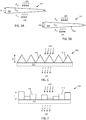
- a second component 220B also propagates the first distance x, where the second component 220B then first propagates a second distance y in air, having the first dielectric constant ⁇ A , and then propagates a third distance H that correspond to a height H of a protruding portion 410 made in a dielectric material having a second dielectric constant ⁇ B .
- the protruding portion 410 is for example made in a plastic material.
- the second dielectric constant ⁇ B is between 2 and 3, for example about 2.6.
- the first component 220A propagates the first distance x in air only, and the second component 220B propagates the first distance x partially in air and partially through the protruding portion 410, the first component 220A and the second component 220B will have mutually different respective relative phases ⁇ 1 , ⁇ 2 after having propagated the first distance x.
- the height H is preferably chosen in the range 0 mm to ⁇ 0 2 2.6 ⁇ 1 .
- the maximum height H then evaluates to approximately 3 mm.
- a side-shield 310 having non-uniform thickness is a side-shield comprising a carrier structure 315 which tapers off in some direction, e.g., as a wedge-shaped side-shield illustrated in Figure 5A that tapers from a thickness z mm to a thickness H+z mm.
- a radar signal component exiting the side-shield then has a phase in dependence of where it penetrated the side-shield since the thickness varies over the side-shield.
- Radar signal components penetrating the side-shield at the thickest end propagates through a material thickness of about H+z mm, while a radar signal component propagating through the thinnest end only experiences a side-shield thickness of about z mm.
- the wedge-shaped side-shield also bends the signal 320 to the left, i.e., the exiting radar signal 320 is not parallel to the incoming signal 220 due to the effects of diffraction by the side-shield. This is a beneficial effect of the wedge - to deviate the energy away from a reflecting surface if it were known that one were present.
- Figure 5B shows an example of a tapered radar side-shield which also comprises uneven surfaces 520 to further randomize the phase of a radar signal propagating though the side-shield.
- a side-shield having non-uniform delay structure is a side-shield comprising a carrier structure 315 and a plurality of protruding portions.
- Examples of different types of protruding portions 610, 710, 810, 1210 are schematically illustrated in Figures 6-8 and 12 .
- Each protruding portion is configured to delay a radar signal 220, 320 propagating through the side-shield 310 by a respective amount, in dependence of a wavelength of the radar signal. Due to the variable delay amounts, the radar signal will comprise components having different phases after propagation through the side-shield. In other words, making the side shield patterned rather than using a typical flat surface has the effect of randomizing the phase front that propagates beyond the side shield. This phase randomization diffuses the radar signal.
- adding pyramids or other protrusions to the inner and/or outer surface of the side-shield 310 will randomize the phases of the signal appearing on the outer surface, thus broadening and reducing the intensity of any side-lobes.
- the plurality of protruding portions 610, 710, 810 are configured to randomize a phase distribution of the radar signal 320 after propagation through the side-shield 310. This can be achieved, e.g., by configuring the protruding portions with different shapes and/or with materials having different dielectric constants.
- at least one of the protruding portions may be formed as a pyramid-shaped protruding portion 610, exemplified in Figure 6 .
- a pyramid-shaped protruding portion 610 will subject a radar signal to different propagation delays depending on where the radar signal propagates through the side-shield.
- the protruding portions may also be formed in other shapes, such as the cuboid-shaped protrusions 710 exemplified in Figure 7 .
- Figure 8 shows pyramid-shaped protruding portions 810 on both sides of a carrier structure 315.
- the pyramid-shaped protruding portions 810 on each side have a height of H/2, such that the total height of the pyramid-shaped protruding portions 810 is H.
- the protruding portions 610, 710, 810 may be arranged on one or both sides of the side-shield, i.e. they may be arranged on a first face of the side-shield and/or on a second face of the side-shield opposite to the first face.
- the protruding portions may also be formed as polygon-shaped protruding portions. A blend of different shapes can be used to generate a desired phase randomization effect.
- the protruding portions 610, 710, 810 are supported by a carrier structure 315. This is, however, optional as indicated with dashed lines for the carrier structure 315 in Figure 6-8 .
- the carrier structure is not necessary if the protruding portions 610, 710, 810 form a coherent piece of material that is self-supporting.
- a carrier structure 315 can have a dielectric constant that is the same as, or differs from, a dielectric constant of the protruding portions 610, 710, 810.
- the carrier structure 315 can also have any suitable shape, for example tapered as shown in Figure 5A .
- Combinations of different types of protruding portions 610, 710, 810 can according to some aspects be used.
- a protruding portion 610, 710, 810 is associated with a height in a range from 0 to H mm, measured in an extension direction of the protruding portion, from the carrier structure 315.
- the height H can be determined in dependence of a radar transmission wavelength in vacuum ⁇ 0 and a dielectric constant ⁇ of a material in the protruding portion.
- the height range can also be selected somewhere in-between in order to generate phase randomization.
- At least some of the side-shields disclosed herein can be cost-effectively manufactured by integrally forming the protruding portions and the carrier structure in a plastic material.
- the radar side-shield 310 may be formed in a single piece by molding a plastic material, which is an advantage.
- Plastic materials may consist of any of a wide range of synthetic or semi-synthetic organic compounds that are malleable and so can be molded into solid objects. Plasticity is the general property of all materials which can deform irreversibly without breaking but, in the class of moldable polymers, this occurs to such a degree that their actual name derives from this specific ability. Plastics are typically organic polymers of high molecular mass and often contain other substances. They are usually synthetic, most commonly derived from petrochemicals.
- the protruding portions 610, 710, 810 can be attached to the carrier portion 315 by any of; an adhesive layer, a snap-fit mechanism, an interference fit mechanism, and/or by ultrasonic welding.
- Thermoplastic olefin (TPO) or other plastic is a preferred material for manufacturing the radar side-shield. Radar absorbing plastics are available, however the properties can be different, it is more expensive, and can be more complicated to mold and weld.
- a phase randomization of a radar signal propagating through the side-shield can also be obtained by adding chunks of material to the carrier structure 315, where the added material is of a different dielectric constant compared to that of the carrier structure material.
- Figure 9 illustrates one such example radar side-shield where the non-uniform delay structure has a non-uniform dielectric constant along the normal vector V.
- the embedded portions 910 are associated with a dielectric constant ⁇ different from a dielectric constant of the carrier structure 315.
- the embedded portions 910 are preferably formed with different shapes to cause the phase randomization discussed above. It is also possible to add embedded portion which have been formed in different materials having different dielectric constants.
- the non-uniform delay structure has a non-uniform dielectric constant along the normal vector V, but a uniform thickness. It is of course conceivable that the non-uniform delay structure according to Figure 9 has a non-uniform thickness as well.
- FIGS 10A and 10B schematically show a side view and a top view of a radar side-shield 310 where an irregular or piecewise linear trench 1010 has been formed in the side-shield surface. This trench also has the effect of randomizing phase distribution.
- the side-shield 310 can also be formed having an irregular or zig-zag shaped surface, as exemplified in the side-view shown in Figure 10C.
- Figure 10C shows a side view of a radar side-shield 310 with zig zag pattern on inner and outer surfaces. This has the advantage of a more constant material thickness for molding. Both top and bottom surfaces of the side-shield 310 take on the irregular shape in order to maintain a more constant thickness of material for ease of molding.
- Figure 11 schematically illustrates a radar transceiver assembly 1100 where zig-zag trenches have been formed into the (normally flat) surface of the radar side-shield 310 that here is shown together with the radar transceiver 130.
- the one or more protruding portions 1210 are comprised within a part of a surface of the carrier structure 315, as exemplified in Figure 12 which shows an example radar transceiver assembly 1200 comprising a radar transceiver 130 and a side-shield 310 according to the discussion above.
- Figure 13 is a flow chart illustrating methods.
- a method for producing a side-shield 310 for a radar transceiver 130 comprises; configuring S1 a mold for molding a plastic element, wherein the mold is configured to form one or more protruding portions arranged protruding from a carrier structure 315 of the side-shield and/or an irregular trench in a surface of the side-shield, and producing S2 the side-shield 310 by forming a plastic material by the mold.
- the radar transceiver 130 can according to some aspects be completely or partially circumvented by the radar side-shield 310, or positioned at an offset distance from the radar side-shield 310.
Landscapes
- Engineering & Computer Science (AREA)
- Radar, Positioning & Navigation (AREA)
- Remote Sensing (AREA)
- Physics & Mathematics (AREA)
- Computer Networks & Wireless Communication (AREA)
- General Physics & Mathematics (AREA)
- Electromagnetism (AREA)
- Computer Security & Cryptography (AREA)
- Radar Systems Or Details Thereof (AREA)
Abstract
Description
- The present disclosure relates to radar transceivers and in particular to installation of radar transceivers in vehicles.
- A radar transceiver is a device arranged for transmission and reception of radar signals in a radar frequency band. Radar transceivers are commonly used in vehicles for monitoring vehicle surroundings. Automatic Cruise Control (ACC) functions, Emergency Braking (EB) functions, Advanced Driver Assistance Systems (ADAS) and Autonomous Drive (AD) are some examples of applications where radar data represents an important source of information on which vehicle control may be based.
- Vehicle radar transceivers are often arranged hidden behind vehicle body parts, such as a front or a rear vehicle bumper. This placement is often chosen due to aesthetic reasons, but there is also a need to protect the radar transceiver from mechanical impact, moisture and dirt.
- A drawback associated with hiding transceivers behind vehicle body parts is that the radar transmission must penetrate the body part in order to monitor the vehicle surroundings. Some of the radar energy is often reflected back from the body part into the cavity behind the body part. This reflected radar energy may appear as a false target, and thus cause erroneous radar target detections.
- Some work has been done towards improving the situation;
CN 108016388 discloses a vehicle bumper comprising a layered structure configured to reduce reflection. -
DE 102010028185 relates to vehicle body parts suitable for use with radar transceivers. - Another issue related to radar systems in vehicular applications is the overall system cost. It is desired to reduce cost of the overall vehicle, meaning that the cost of the radar system and its mounting on the vehicle should be kept at a minimum.
- It is an object of the present disclosure to provide improved radar transceiver assemblies and installation techniques. This object is achieved by a side-shield for a radar transceiver. The side-shield comprises a non-uniform delay structure arranged over the side-shield, the non-uniform delay structure being configured to delay a radar signal propagating through the side-shield by a variable amount in dependence of a wavelength of the radar signal and in dependence of a location on the side-shield surface through which the radar signal propagates, thereby steering and/or diffusing the radar signal after propagation through the side-shield. Thus, any focused radar signal energy propagating though the side-shield is de-focused by the phase randomization. This alleviates problems with false detections incurred by reflections in vehicle body parts.
- According to aspects, the non-uniform delay structure has a variable thickness measured along a normal vector of a surface of the side-shield and/or a non-uniform dielectric constant measured along the normal vector. Thus, the side-shield can be cost-effectively manufactured by, e.g., molding.
- Further advantages are obtained by the dependent claims.
- There are also disclosed herein radar transceivers, assembly methods, and vehicles associated with the above-mentioned advantages.
- The present disclosure will now be described more in detail with reference to the appended drawings, where:
- Figure 1
- shows a schematic top view of a vehicle;
- Figure 2
- illustrates radar reflection by a vehicle body part;
- Figure 3
- illustrates radar reflection with a radar side-shield;
- Figure 4
- illustrates radar propagation through different media.
- Figures 5-10
- illustrate example radar side-shields;
- Figures 11-12
- shows example radar transceiver assemblies; and
- Figure 13
- is a flow chart illustrating a production method.
- The inventive concept will now be described more fully hereinafter with reference to the accompanying drawings, in which certain embodiments of the inventive concept are shown. This inventive concept may, however, be embodied in many different forms and should not be construed as limited to the embodiments set forth herein; rather, these embodiments are provided by way of example so that this disclosure will be thorough and complete, and will fully convey the scope of the inventive concept to those skilled in the art. Like numbers refer to like elements throughout the description. Any step or feature illustrated by dashed lines should be regarded as optional.
-
Figure 1 shows avehicle 100 equipped with avehicle radar system 110. Thesystem 110 comprises acontrol unit 120 and at least oneradar transceiver 130. - The
control unit 120 and theradar transceiver 130 may be comprised in a single physical unit or they may be distributed over more than one physical unit. - According to an example, the
vehicle radar transceiver 130 is arranged for generating and transmitting radar signals in the form of frequency modulated continuous wave (FMCW) signals, sometimes also referred to as radar chirp signals, and to receivereflected radar signals 125, where the transmitted signals have been reflected by anobject 145. - The present disclosure is not limited to FMCW radar waveforms. Rather, the disclosed concepts and techniques can be applied to many different radar waveforms. In particular, the techniques disclosed herein are applicable to Orthogonal Frequency Division Multiplex (OFDM) radar, and to Pulse Modulated Continuous Wave (PMCW) radar. One example of OFDM radar is the stepped OFDM radar waveform described in
EP3323151 A1 . - The
radar transceiver 130 is associated with a field ofview 140. In case the radar transceiver is a front radar, aboresight direction 141 of the radar often coincides with a center line of the field of view, where theboresight direction 141 here also coincides with a forward direction F of thevehicle 100. In case the vehicle radar is instead configured as a side radar or a rearward facing radar, then the boresight direction may point in some other angle compared to the forward direction F of thevehicle 100. - The
radar transceiver 130 is mounted behind a body part of thevehicle 100. This vehicle body part may be, e.g., afront bumper 150 or arear bumper 160. Reflections in a vehicle body part arranged in front of the radar transceiver may give rise to an increased noise floor and to false detections which are of course undesired. One suchfalse detection 170 is indicated inFigure 1 . The radar sensor and/or thecontrol unit 120 cannot easily distinguish between afalse detection 170 and atrue target 145. There may be a plurality offalse targets 170 complicating radar signal processing. - Reflections in a body part such as a
bumper -
Figure 2 schematically illustrates one cause for false detections. Here, theradar transceiver 130 is arranged behind abumper 150 which reflects part of the transmittedradar energy 220 back into a cavity behind thebumper 150. The reflected radar energy is incident on somereflective surface 210 on thevehicle 100 which returns the incident reflection. This return may at least in part end up back at theradar transceiver 130. Thus, the radar transceiver receives signal energy which appears to have been reflected of a target, but which in reality is afalse detection 170. The reflected energy may arrive at the radar transceiver via a single reflection or via reflections in more than one vehicle part. - To reduce problems with
false radar detections 170, it is proposed herein to arrange a side-shield in vicinity of theradar transceiver 130. The side-shield is configured to randomize a phase distribution of an electromagnetic wave propagating though the shield. - If the radar signal has been focused by the shape of a vehicle body part, such as a bumper, into a narrow sidelobe (somewhat similar to a satellite dish effect), then the transmission power density may be increased, e.g., 10dB higher than if the body part was flat. When this focused beam hits the side shield, if it is flat, the phase front will emerge on the far side of the side-shield medium substantially parallel to when it arrived and hence the focused beam will continue to stay focused. However, if the phase front of the
radar signal 220 is randomized by propagation through a phase randomizing side-shield, then the beam is no long focused after side-shield penetration and the energy density (in terms of power per solid angle) is reduced. In other words, by randomizing the phase distribution of the radar signal, the radar signal is steered or diffused by the side-shield. This of course happens in both transmit and receive directions. Randomizing a phase distribution here means that the phase front across an outer 2-dimensional surface of a radar side-shield has become randomized, which, e.g., removes any focusing effect that had been achieved by a vehicle body part like a bumper. -
Figure 3 shows an example of aradar transceiver assembly 300 comprising this type of phase randomizing side-shield 310. A radar side-shield 310 is normally arranged laterally with respect to a transmission direction of theradar transceiver 130, i.e., extending out from the sides of the transceiver housing as schematically illustrated inFigure 3 . The radar side shield extends in an extension plane, such as laterally out from the radar transceiver. However, the side-shield surface may be either planar or curved. - The side-
shields 310 discussed herein all comprise a non-uniform delay structure arranged over the extension plane of the side-shield. The non-uniform delay structure is configured to delay aradar signal shield 310 by a variable amount in dependence of a wavelength of the radar signal and in dependence of a location on the side-shield through which location the radar signal propagates. This means that the structure is non-uniform in the sense that the phase of a signal component exiting the side-shield 310 depends on where, spatially, the signal component interacts with the side-shield. The effect of the side-shield is a randomization of a phase distribution of theradar signal 320 after propagation through the side-shield 310 as discussed above. - According to some aspects, the randomized phase distribution is a uniform phase distribution over some angular range, such as from 0 to π or 0 to 2π.
- The side-shield can be configured with a non-uniform delay structure to generate the phase randomization in some different ways. For instance, according to some aspects, the non-uniform delay structure has a non-uniform (variable) thickness measured along a normal vector V to the extension plane.
- In general, the wavelength of a transmitted radar signal in vacuum, denoted λ 0, is altered when the radar signal propagates through a material having a dielectric constant ε different from the vacuum permittivity ε0 to


- The signal velocity is the speed at which a wave propagates. Signal velocity is usually equal to group velocity (the speed of a short "pulse" or of a wave-packet's middle or "envelope"). However, in a few special cases (e.g., media designed to amplify the front-most parts of a pulse and then attenuate the back section of the pulse), group velocity can exceed the speed of light in vacuum, while the signal velocity will still be less than or equal to the speed of light in vacuum.
- In a transmission medium, signal velocity vs is the reciprocal of the square root of the capacitance-inductance product, where inductance and capacitance are typically expressed as per-unit length;

- With reference to
Figure 4 , consider twocomponents first component 220A propagates a first distance x in air, having a first dielectric constant εA. Asecond component 220B also propagates the first distance x, where thesecond component 220B then first propagates a second distance y in air, having the first dielectric constant εA, and then propagates a third distance H that correspond to a height H of a protrudingportion 410 made in a dielectric material having a second dielectric constant εB. The protrudingportion 410 is for example made in a plastic material. According to some aspects, the second dielectric constant εB is between 2 and 3, for example about 2.6. - Since the
first component 220A propagates the first distance x in air only, and thesecond component 220B propagates the first distance x partially in air and partially through the protrudingportion 410, thefirst component 220A and thesecond component 220B will have mutually different respective relative phases ϕ1, ϕ2 after having propagated the first distance x. - These relative phases ϕ1, ϕ2 of the two
components 

- In order to randomize ϕ2 relative to ϕ1 within an approximate range from 0 to π, the height H is preferably chosen in the range 0 mm to

- Rays at other incidence angles than the normal angle will of course have a larger phase difference since the effective distance through the plastic cuboid-shaped protruding element will be longer.
- One example of a side-
shield 310 having non-uniform thickness is a side-shield comprising acarrier structure 315 which tapers off in some direction, e.g., as a wedge-shaped side-shield illustrated inFigure 5A that tapers from a thickness z mm to a thickness H+z mm. A radar signal component exiting the side-shield then has a phase in dependence of where it penetrated the side-shield since the thickness varies over the side-shield. Radar signal components penetrating the side-shield at the thickest end propagates through a material thickness of about H+z mm, while a radar signal component propagating through the thinnest end only experiences a side-shield thickness of about z mm. The wedge-shaped side-shield also bends thesignal 320 to the left, i.e., the exitingradar signal 320 is not parallel to theincoming signal 220 due to the effects of diffraction by the side-shield. This is a beneficial effect of the wedge - to deviate the energy away from a reflecting surface if it were known that one were present. -
Figure 5B shows an example of a tapered radar side-shield which also comprisesuneven surfaces 520 to further randomize the phase of a radar signal propagating though the side-shield. - Another example of a side-shield having non-uniform delay structure is a side-shield comprising a
carrier structure 315 and a plurality of protruding portions. Examples of different types of protrudingportions Figures 6-8 and12 . Each protruding portion is configured to delay aradar signal shield 310 by a respective amount, in dependence of a wavelength of the radar signal. Due to the variable delay amounts, the radar signal will comprise components having different phases after propagation through the side-shield. In other words, making the side shield patterned rather than using a typical flat surface has the effect of randomizing the phase front that propagates beyond the side shield. This phase randomization diffuses the radar signal. - For example, adding pyramids or other protrusions to the inner and/or outer surface of the side-
shield 310 will randomize the phases of the signal appearing on the outer surface, thus broadening and reducing the intensity of any side-lobes. - With reference to the examples shown in
Figures 6-8 , the plurality of protrudingportions radar signal 320 after propagation through the side-shield 310. This can be achieved, e.g., by configuring the protruding portions with different shapes and/or with materials having different dielectric constants. For instance, at least one of the protruding portions may be formed as a pyramid-shaped protrudingportion 610, exemplified inFigure 6 . A pyramid-shaped protrudingportion 610 will subject a radar signal to different propagation delays depending on where the radar signal propagates through the side-shield. The protruding portions may also be formed in other shapes, such as the cuboid-shapedprotrusions 710 exemplified inFigure 7 . -
Figure 8 shows pyramid-shaped protrudingportions 810 on both sides of acarrier structure 315. The pyramid-shaped protrudingportions 810 on each side have a height of H/2, such that the total height of the pyramid-shaped protrudingportions 810 is H. - This is applicable for all types of protruding portions, according to some aspects the protruding
portions - The protruding portions may also be formed as polygon-shaped protruding portions. A blend of different shapes can be used to generate a desired phase randomization effect.
- According to some aspects, as shown in
Figure 6-8 , the protrudingportions carrier structure 315. This is, however, optional as indicated with dashed lines for thecarrier structure 315 inFigure 6-8 . The carrier structure is not necessary if the protrudingportions - If a
carrier structure 315 is used, such a carrier structure can have a dielectric constant that is the same as, or differs from, a dielectric constant of the protrudingportions carrier structure 315 can also have any suitable shape, for example tapered as shown inFigure 5A . - Combinations of different types of protruding
portions - According to some aspects, a protruding
portion carrier structure 315. The height H can be determined in dependence of a radar transmission wavelength in vacuum λ 0 and a dielectric constant ε of a material in the protruding portion. For example, a height range from 0 to H mm can be determined as

- At least some of the side-shields disclosed herein can be cost-effectively manufactured by integrally forming the protruding portions and the carrier structure in a plastic material. I.e., the radar side-
shield 310 may be formed in a single piece by molding a plastic material, which is an advantage. - Plastic materials may consist of any of a wide range of synthetic or semi-synthetic organic compounds that are malleable and so can be molded into solid objects. Plasticity is the general property of all materials which can deform irreversibly without breaking but, in the class of moldable polymers, this occurs to such a degree that their actual name derives from this specific ability. Plastics are typically organic polymers of high molecular mass and often contain other substances. They are usually synthetic, most commonly derived from petrochemicals.
- Alternatively, or as a complement to molding the side-shield in a single piece, the protruding
portions carrier portion 315 by any of; an adhesive layer, a snap-fit mechanism, an interference fit mechanism, and/or by ultrasonic welding. - Thermoplastic olefin (TPO) or other plastic is a preferred material for manufacturing the radar side-shield. Radar absorbing plastics are available, however the properties can be different, it is more expensive, and can be more complicated to mold and weld.
- A phase randomization of a radar signal propagating through the side-shield can also be obtained by adding chunks of material to the
carrier structure 315, where the added material is of a different dielectric constant compared to that of the carrier structure material. -
Figure 9 illustrates one such example radar side-shield where the non-uniform delay structure has a non-uniform dielectric constant along the normal vector V. This means that the dielectric constant experienced by an electromagnetic signal component propagating through the side-shield is different at different locations over theside shield 310. The embeddedportions 910 are associated with a dielectric constant ε different from a dielectric constant of thecarrier structure 315. The embeddedportions 910 are preferably formed with different shapes to cause the phase randomization discussed above. It is also possible to add embedded portion which have been formed in different materials having different dielectric constants. According to some aspects, the non-uniform delay structure has a non-uniform dielectric constant along the normal vector V, but a uniform thickness. It is of course conceivable that the non-uniform delay structure according toFigure 9 has a non-uniform thickness as well. -
Figures 10A and 10B schematically show a side view and a top view of a radar side-shield 310 where an irregular or piecewiselinear trench 1010 has been formed in the side-shield surface. This trench also has the effect of randomizing phase distribution. - The side-
shield 310 can also be formed having an irregular or zig-zag shaped surface, as exemplified in the side-view shown inFigure 10C. Figure 10C shows a side view of a radar side-shield 310 with zig zag pattern on inner and outer surfaces. This has the advantage of a more constant material thickness for molding. Both top and bottom surfaces of the side-shield 310 take on the irregular shape in order to maintain a more constant thickness of material for ease of molding. -
Figure 11 schematically illustrates aradar transceiver assembly 1100 where zig-zag trenches have been formed into the (normally flat) surface of the radar side-shield 310 that here is shown together with theradar transceiver 130. - It may not be necessary to add the protruding portions to the entire side-shield. Thus, according to some aspects, the one or more
protruding portions 1210 are comprised within a part of a surface of thecarrier structure 315, as exemplified inFigure 12 which shows an exampleradar transceiver assembly 1200 comprising aradar transceiver 130 and a side-shield 310 according to the discussion above. -
Figure 13 is a flow chart illustrating methods. In particular, there is illustrated a method for producing a side-shield 310 for aradar transceiver 130. The method comprises; configuring S1 a mold for molding a plastic element, wherein the mold is configured to form one or more protruding portions arranged protruding from acarrier structure 315 of the side-shield and/or an irregular trench in a surface of the side-shield, and producing S2 the side-shield 310 by forming a plastic material by the mold. - The present disclosure is not limited to the examples described above, but may vary freely within the scope of the appended claims. For example, the
radar transceiver 130 can according to some aspects be completely or partially circumvented by the radar side-shield 310, or positioned at an offset distance from the radar side-shield 310.
Claims (15)
- A side-shield (310) for a radar transceiver (130), the side-shield (310) comprising a non-uniform delay structure arranged over the side-shield, the non-uniform delay structure being configured to delay a radar signal (220, 320) propagating through the side-shield (310) by a variable amount in dependence of a wavelength of the radar signal and in dependence of a location on the side-shield surface through which the radar signal (220, 320) propagates, thereby steering and/or diffusing the radar signal (320) after propagation through the side-shield (310).
- The side-shield (310) according to claim 1, wherein the non-uniform delay structure has a variable thickness measured along a normal vector (V) of a surface of the side-shield and/or a non-uniform dielectric constant measured along the normal vector (V).
- The side-shield (310) according to claim 1 or 2, wherein the randomized phase distribution is a uniform phase distribution.
- The side-shield (310) according to any previous claim, the side-shield (310) comprising a carrier structure (315) and a plurality of protruding portions (610, 710, 810, 1210), wherein each protruding portion is configured to delay a radar signal (220, 320) propagating through the side-shield (310) by a respective and variable amount in dependence of a wavelength of the radar signal, thereby randomizing a phase distribution of the radar signal (320) after propagation through the side-shield (310).
- The side-shield (310) according to claim 4, wherein the protruding portions and the carrier structure are integrally formed in a plastic material.
- The side-shield (310) according to any of claims 4-5, wherein the protruding portions (610, 710, 810, 1210) are attached to the carrier portion (315) by any of; an adhesive layer, a snap-fit mechanism, an interference fit mechanism, and/or by ultrasonic welding.
- The side-shield (310) according to any of claims 4-6, wherein a protruding portion (610, 710, 810, 1210) is associated with a height in a range from 0 to H mm, measured from the carrier structure (315) in an extension direction of the protruding portion, wherein the height H is determined in dependence of a radar transmission wavelength in vacuum λ 0 and a dielectric constant ε of a material in the protruding portion (610, 710, 810).
- The side-shield (310) according to claim 7, wherein the height H is determined as

- The side-shield (310) according to claim 6 or 7, wherein the height H is in a range 2-4 mm, and preferably about 3 mm.
- The side-shield (310) according to any previous claim, wherein at least one of the protruding portions is a pyramid-shaped protruding portion (610, 810, 1210), a cuboid-shaped protruding portion (710), an irregular or piecewise linear trench, or a polygon-shaped protruding portion.
- The side-shield (310) according to any previous claim, comprising one or more embedded portions (910), wherein the embedded portions (910) are associated with a dielectric constant ε different from a dielectric constant εc of a carrier structure (315) of the side-shield (310).
- The side-shield (310) according to any previous claim, wherein the one or more protruding portions (1210) are comprised within a part of a surface of the carrier structure (315).
- A radar transceiver assembly (1100, 1200) comprising a radar transceiver (130) and a side-shield (310) according to any previous claim.
- A vehicle (100) comprising the radar transceiver assembly (1100, 1200) according to claim 13.
- A method for producing a side-shield (310) for a radar transceiver (130), the method comprising;
configuring (S1) a mold for molding a plastic element,
wherein the mold is configured to form one or more protruding portions (610, 710, 810, 1210) arranged protruding from a carrier structure (315) of the side-shield and/or an irregular trench in a surface of the side-shield (310), and
producing (S2) the side-shield (310) by forming a plastic material by the mold.
Priority Applications (4)
| Application Number | Priority Date | Filing Date | Title |
|---|---|---|---|
| EP19199391.4A EP3798676A1 (en) | 2019-09-24 | 2019-09-24 | A radar side-shield and a radar transceiver assembly |
| CN202080064878.5A CN114402223A (en) | 2019-09-24 | 2020-09-22 | Radar side shield and radar transceiver assembly |
| PCT/EP2020/076356 WO2021058450A1 (en) | 2019-09-24 | 2020-09-22 | A radar side-shield and a radar transceiver assembly |
| US17/763,465 US20220349990A1 (en) | 2019-09-24 | 2020-09-22 | A radar side-shield and a radar transceiver assembly |
Applications Claiming Priority (1)
| Application Number | Priority Date | Filing Date | Title |
|---|---|---|---|
| EP19199391.4A EP3798676A1 (en) | 2019-09-24 | 2019-09-24 | A radar side-shield and a radar transceiver assembly |
Publications (1)
| Publication Number | Publication Date |
|---|---|
| EP3798676A1 true EP3798676A1 (en) | 2021-03-31 |
Family
ID=68066708
Family Applications (1)
| Application Number | Title | Priority Date | Filing Date |
|---|---|---|---|
| EP19199391.4A Pending EP3798676A1 (en) | 2019-09-24 | 2019-09-24 | A radar side-shield and a radar transceiver assembly |
Country Status (4)
| Country | Link |
|---|---|
| US (1) | US20220349990A1 (en) |
| EP (1) | EP3798676A1 (en) |
| CN (1) | CN114402223A (en) |
| WO (1) | WO2021058450A1 (en) |
Cited By (1)
| Publication number | Priority date | Publication date | Assignee | Title |
|---|---|---|---|---|
| EP4336208A4 (en) * | 2021-06-10 | 2024-05-08 | Stanley Electric Co Ltd | Lamp device |
Families Citing this family (10)
| Publication number | Priority date | Publication date | Assignee | Title |
|---|---|---|---|---|
| US20220384942A1 (en) * | 2021-06-01 | 2022-12-01 | Aptiv Technologies Limited | Wave-Shaped Ground Structure for Antenna Arrays |
| JPWO2023003033A1 (en) | 2021-07-21 | 2023-01-26 | ||
| JPWO2023003035A1 (en) | 2021-07-21 | 2023-01-26 | ||
| WO2023003034A1 (en) | 2021-07-21 | 2023-01-26 | 日東電工株式会社 | Electromagnetic wave shield |
| WO2023013753A1 (en) | 2021-08-05 | 2023-02-09 | 日東電工株式会社 | Electromagnetic wave shield |
| CN116762238A (en) | 2021-08-06 | 2023-09-15 | 日东电工株式会社 | Electromagnetic wave shield and assembly |
| CN117916618A (en) | 2021-09-03 | 2024-04-19 | 日东电工株式会社 | Electromagnetic wave shield |
| EP4148901A1 (en) | 2021-09-09 | 2023-03-15 | Aptiv Technologies Limited | Antenna |
| CN116888598A (en) | 2021-09-30 | 2023-10-13 | 日东电工株式会社 | Method for designing wave scatterer, device for designing wave scatterer, and program for designing wave scatterer |
| FR3137341A1 (en) * | 2022-06-30 | 2024-01-05 | Psa Automobiles Sa | DETECTION DEVICE WITH REDUCED GHOST TARGETS, FOR A LAND VEHICLE |
Citations (10)
| Publication number | Priority date | Publication date | Assignee | Title |
|---|---|---|---|---|
| WO2008029928A1 (en) | 2006-09-04 | 2008-03-13 | Toyota Jidosha Kabushiki Kaisha | Antenna apparatus |
| US20090058739A1 (en) | 2006-02-28 | 2009-03-05 | Fujitsu Limited | Antenna device, electronic device and antenna cover |
| DE102010028185A1 (en) | 2010-04-26 | 2011-10-27 | Bayerische Motoren Werke Aktiengesellschaft | Vehicle, has radar apparatus arranged behind body component i.e. bumper, of vehicle, adjustment area arranged between radar apparatus and body component of vehicle, where adjustment area comprises recesses |
| US20140070982A1 (en) | 2011-04-19 | 2014-03-13 | Mazda Motor Corporation | Obstacle detection device for vehicle |
| US20150207217A1 (en) * | 2012-07-13 | 2015-07-23 | Denso Corporation | Radar apparatus |
| US20160268693A1 (en) | 2015-03-12 | 2016-09-15 | Autoliv Asp, Inc. | Apparatus and method for mitigating multipath effects and improving absorption of an automotive radar module |
| US20160370456A1 (en) | 2015-06-17 | 2016-12-22 | Volvo Car Corporation | Low reflection radar bracket |
| CN108016388A (en) | 2017-11-24 | 2018-05-11 | 华域汽车系统股份有限公司 | A kind of bumper suitable for vehicle-mounted millimeter wave radar |
| EP3323151A1 (en) | 2015-07-16 | 2018-05-23 | Aledia | Optoelectronic device comprising three-dimensional semiconductor elements, and method for manufacturing said device |
| US20190067827A1 (en) * | 2016-02-23 | 2019-02-28 | Denso Corporation | Antenna apparatus |
Family Cites Families (10)
| Publication number | Priority date | Publication date | Assignee | Title |
|---|---|---|---|---|
| US4148039A (en) * | 1977-07-05 | 1979-04-03 | The Boeing Company | Low reflectivity radome |
| US4901080A (en) * | 1988-07-06 | 1990-02-13 | Northrop Corporation | Radar test device with planar reflecting shield |
| US5298906A (en) * | 1993-03-31 | 1994-03-29 | Raytheon Company | Antenna isolation for continuous wave radar systems |
| JP5953969B2 (en) * | 2012-06-14 | 2016-07-20 | 株式会社デンソー | Radar equipment |
| US9024804B2 (en) * | 2012-09-14 | 2015-05-05 | Delphi Technologies, Inc. | Partial covering radome for a radar unit |
| US9231310B2 (en) * | 2013-09-24 | 2016-01-05 | Delphi Technologies, Inc. | Radar sensor antenna with anti-reflection element |
| US9970806B2 (en) * | 2015-04-30 | 2018-05-15 | Rosemount Tank Radar Ab | Single conductor probe radar level gauge system and method for a tank having a tubular mounting structure |
| EP3276748B1 (en) * | 2016-07-29 | 2019-05-29 | 3M Innovative Properties Company | Radar radiation redirecting tape |
| WO2018077827A1 (en) * | 2016-10-24 | 2018-05-03 | Zanini Auto Grup, S.A. | Radome for vehicles |
| JP2018028551A (en) * | 2017-10-23 | 2018-02-22 | 古河電気工業株式会社 | Arrangement structure of radar device |
-
2019
- 2019-09-24 EP EP19199391.4A patent/EP3798676A1/en active Pending
-
2020
- 2020-09-22 US US17/763,465 patent/US20220349990A1/en active Pending
- 2020-09-22 CN CN202080064878.5A patent/CN114402223A/en active Pending
- 2020-09-22 WO PCT/EP2020/076356 patent/WO2021058450A1/en active Application Filing
Patent Citations (10)
| Publication number | Priority date | Publication date | Assignee | Title |
|---|---|---|---|---|
| US20090058739A1 (en) | 2006-02-28 | 2009-03-05 | Fujitsu Limited | Antenna device, electronic device and antenna cover |
| WO2008029928A1 (en) | 2006-09-04 | 2008-03-13 | Toyota Jidosha Kabushiki Kaisha | Antenna apparatus |
| DE102010028185A1 (en) | 2010-04-26 | 2011-10-27 | Bayerische Motoren Werke Aktiengesellschaft | Vehicle, has radar apparatus arranged behind body component i.e. bumper, of vehicle, adjustment area arranged between radar apparatus and body component of vehicle, where adjustment area comprises recesses |
| US20140070982A1 (en) | 2011-04-19 | 2014-03-13 | Mazda Motor Corporation | Obstacle detection device for vehicle |
| US20150207217A1 (en) * | 2012-07-13 | 2015-07-23 | Denso Corporation | Radar apparatus |
| US20160268693A1 (en) | 2015-03-12 | 2016-09-15 | Autoliv Asp, Inc. | Apparatus and method for mitigating multipath effects and improving absorption of an automotive radar module |
| US20160370456A1 (en) | 2015-06-17 | 2016-12-22 | Volvo Car Corporation | Low reflection radar bracket |
| EP3323151A1 (en) | 2015-07-16 | 2018-05-23 | Aledia | Optoelectronic device comprising three-dimensional semiconductor elements, and method for manufacturing said device |
| US20190067827A1 (en) * | 2016-02-23 | 2019-02-28 | Denso Corporation | Antenna apparatus |
| CN108016388A (en) | 2017-11-24 | 2018-05-11 | 华域汽车系统股份有限公司 | A kind of bumper suitable for vehicle-mounted millimeter wave radar |
Cited By (1)
| Publication number | Priority date | Publication date | Assignee | Title |
|---|---|---|---|---|
| EP4336208A4 (en) * | 2021-06-10 | 2024-05-08 | Stanley Electric Co Ltd | Lamp device |
Also Published As
| Publication number | Publication date |
|---|---|
| CN114402223A (en) | 2022-04-26 |
| US20220349990A1 (en) | 2022-11-03 |
| WO2021058450A1 (en) | 2021-04-01 |
Similar Documents
| Publication | Publication Date | Title |
|---|---|---|
| US20220349990A1 (en) | A radar side-shield and a radar transceiver assembly | |
| US6005511A (en) | Highway vehicle guidance system | |
| US8344939B2 (en) | Radar sensor for motor vehicles | |
| US7920094B2 (en) | Antenna structure having patch elements | |
| US7151479B2 (en) | Radar sensor for motor vehicles | |
| EP0740166B1 (en) | Compact vehicle based rear and side obstacle detection system including multiple antennae | |
| CN112042053B (en) | Radar system | |
| EP3107151B1 (en) | Low reflection radar bracket | |
| KR100981267B1 (en) | Back-up aid indicator | |
| JP5628824B2 (en) | FMCW radar sensor for vehicles | |
| US11327172B2 (en) | Radar apparatus and objection detection method, and signal processing apparatus therefor | |
| US9140787B2 (en) | Radar sensor for motor vehicles, especially LCA sensor | |
| EP1617234A1 (en) | On-vehicle radar | |
| EP0565047B1 (en) | Radar cross section enhancement using phase conjugated impulse signals | |
| Chipengo et al. | From antenna design to high fidelity, full physics automotive radar sensor corner case simulation | |
| DE102018217774A1 (en) | Radar and light emitting device for vehicles for emitting light and radar radiation as well as method and use | |
| US10871564B2 (en) | Vehicular radar assembly | |
| US11598846B2 (en) | FMCW radar system and method using up and down chirp similarity to determine length of target | |
| JP3272523B2 (en) | Transmitter and receiver antenna separate type radar device | |
| WO2024100144A1 (en) | A radar transceiver holding bracket and radar transceiver assembly | |
| KR101534225B1 (en) | Radar apparatus | |
| EP4163662A1 (en) | Device for improving the transmission behavior of radar waves, external cladding component of a vehicle and vehicle comprising such an external cladding component | |
| CN116718984A (en) | Object with structural interference layer package, system with vehicle and corresponding object | |
| KR100783578B1 (en) | Reflector of radar system for vehicle | |
| JPH10142321A (en) | Millimetric wave radar-loaded vehicle |
Legal Events
| Date | Code | Title | Description |
|---|---|---|---|
| PUAI | Public reference made under article 153(3) epc to a published international application that has entered the european phase |
Free format text: ORIGINAL CODE: 0009012 |
|
| STAA | Information on the status of an ep patent application or granted ep patent |
Free format text: STATUS: THE APPLICATION HAS BEEN PUBLISHED |
|
| AK | Designated contracting states |
Kind code of ref document: A1 Designated state(s): AL AT BE BG CH CY CZ DE DK EE ES FI FR GB GR HR HU IE IS IT LI LT LU LV MC MK MT NL NO PL PT RO RS SE SI SK SM TR |
|
| AX | Request for extension of the european patent |
Extension state: BA ME |
|
| STAA | Information on the status of an ep patent application or granted ep patent |
Free format text: STATUS: REQUEST FOR EXAMINATION WAS MADE |
|
| 17P | Request for examination filed |
Effective date: 20210915 |
|
| RBV | Designated contracting states (corrected) |
Designated state(s): AL AT BE BG CH CY CZ DE DK EE ES FI FR GB GR HR HU IE IS IT LI LT LU LV MC MK MT NL NO PL PT RO RS SE SI SK SM TR |
|
| STAA | Information on the status of an ep patent application or granted ep patent |
Free format text: STATUS: EXAMINATION IS IN PROGRESS |
|
| 17Q | First examination report despatched |
Effective date: 20220602 |
|
| RAP1 | Party data changed (applicant data changed or rights of an application transferred) |
Owner name: ARRIVER SOFTWARE AB |
|
| TPAC | Observations filed by third parties |
Free format text: ORIGINAL CODE: EPIDOSNTIPA |
|
| TPAC | Observations filed by third parties |
Free format text: ORIGINAL CODE: EPIDOSNTIPA |