EP3797939B1 - Control command based adaptive system and method for estimating motion parameters of differential drive vehicles - Google Patents
Control command based adaptive system and method for estimating motion parameters of differential drive vehicles Download PDFInfo
- Publication number
- EP3797939B1 EP3797939B1 EP20191743.2A EP20191743A EP3797939B1 EP 3797939 B1 EP3797939 B1 EP 3797939B1 EP 20191743 A EP20191743 A EP 20191743A EP 3797939 B1 EP3797939 B1 EP 3797939B1
- Authority
- EP
- European Patent Office
- Prior art keywords
- model
- motion parameters
- differential drive
- input signals
- command input
- Prior art date
- Legal status (The legal status is an assumption and is not a legal conclusion. Google has not performed a legal analysis and makes no representation as to the accuracy of the status listed.)
- Active
Links
- 230000033001 locomotion Effects 0.000 title claims description 74
- 238000000034 method Methods 0.000 title claims description 47
- 230000003044 adaptive effect Effects 0.000 title description 14
- 230000001360 synchronised effect Effects 0.000 claims description 35
- 238000005259 measurement Methods 0.000 claims description 27
- 230000008859 change Effects 0.000 claims description 21
- 230000015654 memory Effects 0.000 claims description 21
- 238000010200 validation analysis Methods 0.000 claims description 17
- 230000003068 static effect Effects 0.000 claims description 14
- 230000006870 function Effects 0.000 claims description 13
- 230000004044 response Effects 0.000 claims description 9
- 230000006399 behavior Effects 0.000 claims description 5
- 238000004891 communication Methods 0.000 claims description 4
- 238000013507 mapping Methods 0.000 claims description 4
- 238000012549 training Methods 0.000 claims 2
- 238000002474 experimental method Methods 0.000 description 29
- 230000004807 localization Effects 0.000 description 12
- 238000010586 diagram Methods 0.000 description 10
- 238000012886 linear function Methods 0.000 description 5
- 239000011159 matrix material Substances 0.000 description 5
- 230000008569 process Effects 0.000 description 4
- 238000007796 conventional method Methods 0.000 description 3
- 238000012986 modification Methods 0.000 description 3
- 230000004048 modification Effects 0.000 description 3
- 230000003287 optical effect Effects 0.000 description 3
- 238000012546 transfer Methods 0.000 description 3
- 230000001133 acceleration Effects 0.000 description 2
- 230000003466 anti-cipated effect Effects 0.000 description 2
- 238000011161 development Methods 0.000 description 2
- 235000015429 Mirabilis expansa Nutrition 0.000 description 1
- 244000294411 Mirabilis expansa Species 0.000 description 1
- 230000006978 adaptation Effects 0.000 description 1
- 238000013459 approach Methods 0.000 description 1
- 230000015556 catabolic process Effects 0.000 description 1
- 230000001413 cellular effect Effects 0.000 description 1
- 238000006731 degradation reaction Methods 0.000 description 1
- 230000001419 dependent effect Effects 0.000 description 1
- 230000007613 environmental effect Effects 0.000 description 1
- 230000004927 fusion Effects 0.000 description 1
- 230000002452 interceptive effect Effects 0.000 description 1
- 238000007726 management method Methods 0.000 description 1
- 235000013536 miso Nutrition 0.000 description 1
- 230000002093 peripheral effect Effects 0.000 description 1
- 238000012545 processing Methods 0.000 description 1
- 230000009467 reduction Effects 0.000 description 1
- 238000005070 sampling Methods 0.000 description 1
- 239000004065 semiconductor Substances 0.000 description 1
- 238000012360 testing method Methods 0.000 description 1
- 230000001052 transient effect Effects 0.000 description 1
- 238000013519 translation Methods 0.000 description 1
Images


Classifications
-
- B—PERFORMING OPERATIONS; TRANSPORTING
- B25—HAND TOOLS; PORTABLE POWER-DRIVEN TOOLS; MANIPULATORS
- B25J—MANIPULATORS; CHAMBERS PROVIDED WITH MANIPULATION DEVICES
- B25J9/00—Programme-controlled manipulators
- B25J9/16—Programme controls
- B25J9/1628—Programme controls characterised by the control loop
- B25J9/163—Programme controls characterised by the control loop learning, adaptive, model based, rule based expert control
-
- G—PHYSICS
- G01—MEASURING; TESTING
- G01D—MEASURING NOT SPECIALLY ADAPTED FOR A SPECIFIC VARIABLE; ARRANGEMENTS FOR MEASURING TWO OR MORE VARIABLES NOT COVERED IN A SINGLE OTHER SUBCLASS; TARIFF METERING APPARATUS; MEASURING OR TESTING NOT OTHERWISE PROVIDED FOR
- G01D21/00—Measuring or testing not otherwise provided for
- G01D21/02—Measuring two or more variables by means not covered by a single other subclass
-
- G—PHYSICS
- G05—CONTROLLING; REGULATING
- G05D—SYSTEMS FOR CONTROLLING OR REGULATING NON-ELECTRIC VARIABLES
- G05D1/00—Control of position, course or altitude of land, water, air, or space vehicles, e.g. automatic pilot
- G05D1/02—Control of position or course in two dimensions
- G05D1/021—Control of position or course in two dimensions specially adapted to land vehicles
- G05D1/0212—Control of position or course in two dimensions specially adapted to land vehicles with means for defining a desired trajectory
- G05D1/0221—Control of position or course in two dimensions specially adapted to land vehicles with means for defining a desired trajectory involving a learning process
-
- G—PHYSICS
- G06—COMPUTING; CALCULATING OR COUNTING
- G06F—ELECTRIC DIGITAL DATA PROCESSING
- G06F18/00—Pattern recognition
- G06F18/20—Analysing
- G06F18/21—Design or setup of recognition systems or techniques; Extraction of features in feature space; Blind source separation
- G06F18/214—Generating training patterns; Bootstrap methods, e.g. bagging or boosting
-
- G—PHYSICS
- G06—COMPUTING; CALCULATING OR COUNTING
- G06F—ELECTRIC DIGITAL DATA PROCESSING
- G06F18/00—Pattern recognition
- G06F18/20—Analysing
- G06F18/21—Design or setup of recognition systems or techniques; Extraction of features in feature space; Blind source separation
- G06F18/217—Validation; Performance evaluation; Active pattern learning techniques
-
- G—PHYSICS
- G06—COMPUTING; CALCULATING OR COUNTING
- G06F—ELECTRIC DIGITAL DATA PROCESSING
- G06F18/00—Pattern recognition
- G06F18/20—Analysing
- G06F18/25—Fusion techniques
- G06F18/251—Fusion techniques of input or preprocessed data
-
- G—PHYSICS
- G06—COMPUTING; CALCULATING OR COUNTING
- G06N—COMPUTING ARRANGEMENTS BASED ON SPECIFIC COMPUTATIONAL MODELS
- G06N20/00—Machine learning
-
- B—PERFORMING OPERATIONS; TRANSPORTING
- B25—HAND TOOLS; PORTABLE POWER-DRIVEN TOOLS; MANIPULATORS
- B25J—MANIPULATORS; CHAMBERS PROVIDED WITH MANIPULATION DEVICES
- B25J9/00—Programme-controlled manipulators
- B25J9/16—Programme controls
- B25J9/1656—Programme controls characterised by programming, planning systems for manipulators
- B25J9/1664—Programme controls characterised by programming, planning systems for manipulators characterised by motion, path, trajectory planning
Definitions
- the invention generally relates to the field of estimating motion parameters, more particularly, to control command based adaptive system and method for estimating motion parameters of differential drive vehicles.
- the embodiments herein provide control command based adaptive system and method for estimating motion parameters of differential drive vehicles.
- the typical interpretation of results obtained from conventional motion parameter estimation methods has been modified to solve a problem of accurate localization of vehicles and/or robots using only interceptive sensors and adapting to challenging scenarios such as presence of different terrains, change in payload of the differential vehicle, friction, and the like.
- the method of present disclosure utilizes a plurality of time synchronized command input signals provided to mobile robot of the differential drive vehicle for estimation of velocity thereof. Further, an experimental model has been generated, which provides relationship between the plurality of time synchronized command input signals and the velocity of the differential drive vehicle.
- the generated experimental model was adaptively updated to compute one or more motion parameters of the differential drive vehicle in real time, by fusing information from a plurality of sensors, the plurality of time synchronized command input signals and orientation information received from an onboard Inertial Measurement Unit (IMU).
- IMU Inertial Measurement Unit
- FIG. 1 through FIG. 8R where similar reference characters denote corresponding features consistently throughout the figures, there are shown preferred embodiments and these embodiments are described in the context of the following exemplary system and/or method.
- FIG. 1 illustrates an exemplary robot network environment 100 with a system 104 for implementing control command based adaptive system and method for estimating motion parameters of differential drive vehicles, in accordance with an embodiment of present disclosure.
- the robot network environment 100 utilizes a plurality of sensors 106 and the system 104 for estimating motion parameters of differential drive vehicle 102.
- the differential drive vehicle 102 is an autonomous four wheeled mobile robot which moves in the robot network environment.
- the robot network environment includes an indoor network area as well as outdoor network area where the differential drive vehicle moves on different surface terrains.
- the system 104 can be implemented as a unit within the differential drive vehicle 102. In an embodiment, the system 104 can be implemented as a stand-alone unit separated from the differential drive vehicle 102. In an embodiment, the plurality of sensors 106 may reside in the system 104 and/or may act as standalone unit. The system 104 is configured to process and analyze the data received from the plurality of sensors 106, and differential drive vehicle 102 for estimating motion parameters using control command input based adaptive methods. The system 104 is configured to process and analyze the received data in accordance with a plurality of models, further explained in conjunction with FIG. 2 through FIG. 5 , and FIG. 7 .
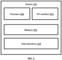
- FIG. 2 illustrates a block diagram of the system 104 of FIG. 1 for control command based adaptive system and method for estimating motion parameters of differential drive vehicles in the robot network environment 100 of FIG. 1 , according to some embodiments of the present disclosure.
- the system 104 includes or is otherwise in communication with one or more hardware processors such as a processor 206, an Input/Output interface 204, and at least one memory such as a memory 202.
- the processor 206, the I/O interface 204, and the memory 202 may be coupled by a system bus (not shown in FIG. 2 ).
- the I/O interface 204 may include a variety of software and hardware interfaces, for example, a web interface, a graphical user interface, and the like.
- the interfaces 204 may include a variety of software and hardware interfaces, for example, interfaces for peripheral device(s), such as a keyboard, a mouse, an external memory, a camera device, and a printer.
- the interfaces 204 can facilitate multiple communications within a wide variety of networks and protocol types, including wired networks, for example, local area network (LAN), cable, etc., and wireless networks, such as Wireless LAN (WLAN), cellular, or satellite.
- the interfaces 204 may include one or more ports for connecting a number of computing systems with one another or to another server computer.
- the I/O interface 204 may include one or more ports for connecting a number of devices to one another or to another server.
- the hardware processor 206 may be implemented as one or more microprocessors, microcomputers, microcontrollers, digital signal processors, central processing units, state machines, combinational circuits, application specific integrated circuits, semiconductor devices, logic circuitries including switches, and/or any devices that manipulate signals based on operational instructions.
- the hardware processor 206 is configured to fetch and execute computer-readable instructions stored in the memory 202.
- the memory 202 may include any computer-readable medium known in the art including, for example, volatile memory, such as static random access memory (SRAM) and dynamic random access memory (DRAM), and/or non-volatile memory, such as read only memory (ROM), erasable programmable ROM, flash memories, hard disks, optical disks, and magnetic tapes.
- the memory 202 includes a data repository 210 for storing data processed, received, and generated as output(s) by the system 104.
- the memory 202 stores a plurality of models such as known non-linear model, generated experimental model (alternatively referred as offline models) and adaptively updated models (alternatively referred as online models) which are further used for estimating motion parameters of differential drive vehicles in the robot network environment 100.
- the plurality of models stored in the memory 202 may include routines, programs, objects, components, data structures, and so on, which perform particular tasks or implement particular (abstract) data types.
- the data repository 210 includes a system database and other data.
- the system database may store information but are not limited to, a plurality of parameters obtained from the plurality of sensors, wherein the parameters are specific to an entity (e.g., machine such as robot, vehicle, and the like).
- the plurality of parameters may comprise sensor data captured through the plurality of sensors connected to the machine.
- the database 208 stores information pertaining to inputs fed to the system 104 and/or outputs generated by the system (e.g., at each stage), specific to the methodology described herein. More specifically, the system database stores information being processed at each step of the proposed methodology.
- the other data may include, data generated as a result of the execution of the plurality of models stored in the memory 202. The generated data may be further learnt to provide improved learning of the plurality of models in the next iterations to output desired results with improved accuracy.
- the one or more hardware processors 206 can be configured to perform control command based adaptive method for estimating motion parameters of differential drive vehicles which can be carried out by using methodology, described in conjunction with FIG. 3 , FIG. 4 , and use case examples.
- FIG. 3 illustrate an exemplary flow diagram of a processor implemented method 300, implemented by the system 104 of FIG. 1 and FIG. 2 for implementing control command based adaptive method for estimating motion parameters of differential drive vehicles, in accordance with some embodiments of the present disclosure.
- the one or more hardware processors 206 input one or more time synchronized command input signals to a moving differential drive vehicle.
- the one or more time synchronized command input signals correspond to giving control commands for different movements of the moving autonomous vehicle.
- the time synchronized command input signals could be but not limited to a command for forward motion of vehicle, command for rotation of vehicle and the like.
- the time synchronized command input signals could be but not limited to a step signal, a ramp signal, an impulse signal, and the like.
- the differential drive vehicle is an autonomous robot having four wheels in which rotation is achieved by a differential push on wheel pairs at opposite sides.
- FIG. 4 illustrates a diagram characterizing motion of the differential drive vehicle in 2D space, in accordance with some embodiments of the present disclosure.
- a reference frame (alternatively referred as inertial frame) and a vehicle's body frame are defined.
- origin of the vehicle's body frame is fixed to vehicle's centre of mass, and it's axes ( X B , Y B ) are always aligned to vehicle's front and left directions.
- the reference frame is fixed, whereas the vehicle's body frame moves around the reference frame.
- [ p x p y ] T and ⁇ represent translation and rotation of the vehicle's body frame F B with respect to the reference frame F 1 expressed in F 1 respectively.
- v represents forward velocity of the vehicle's body frame F B with respect to the reference frame F 1 expressed in F B .
- [ v x v y ] T and ⁇ represent linear and angular velocities of the vehicle's body frame F B with respect to the reference frame F 1 expressed in F 1 respectively.
- equation (i) helps in determining how vehicle states represented by ([ p x , p y ⁇ ] T ) evolves over time when linear and angular velocities ([ v x v y ] T ) are known.
- ⁇ and ⁇ are estimated using a low cost 9-Degrees of freedom (Dof) inertial measurement unit (IMU) which provides information about linear accelerations, angular rates and magnetometer readings.
- Dof 9-Degrees of freedom
- IMU inertial measurement unit
- the one or more hardware processors 206 determine a corresponding change in one or more motion parameters of the moving differential drive vehicle based on the one or more time synchronized command input signals.
- the one or more motion parameters could be but not limited to forward velocity, angle of rotation, change in position of the vehicle, and the like. For example, initially, a first command input signal c 1 is applied as step signal for forward motion of the vehicle, and a second command input signal for rotation of the vehicle is considered zero. Then, in such a case, a corresponding change in the value of forward velocity and position is determined.
- the forward velocity v is computed by sequentially differentiating position estimates of the vehicle obtained using a known in the art ground truth system.
- the ground truth system is created to store a range of values specific to the one or more motion parameters of the differential vehicle, wherein the range of values specific to the one or more motion parameters are obtained by using a set of cameras device in real time.
- the set of cameras may include but not limited to a monocular camera, a RGB-depth camera, an infrared camera, and a stereo-vision camera.
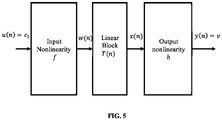
- the one or more hardware processors train a non-linear model by using the one or more time synchronized command input signals and the determined corresponding change in the one or more motion parameters. Further, as depicted in step 308 of FIG. 3 , the one or more hardware processors 206 generate, using the trained non-linear model, an experimental model by computing a mapping function between the one or more time synchronized command input signals and the one or more motion parameters of the differential drive vehicle.
- the non-linear model (alternatively referred as an offline model and may be interchangeably used herein after) could be but not limited to a Hammerstein wiener model. FIG.
- the Hammerstein-Wiener model describes a dynamic system using dynamic linear block in series with static nonlinear blocks.
- the Hammerstein-Wiener model comprises an input non-linearity block, a linear block, and an output non-linearity block.
- the input non-linearity block of the Hammerstein-Wiener model captures nonlinearity present in input data which is referred as input nonlinearity and represented by a non-linear function f .
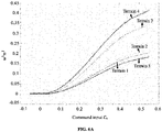
- FIGS. 6A through 6C show graphs depicting outputs of different blocks of the Hammerstein-Weiner model for different terrains, in accordance with some embodiments of the present disclosure.
- the non-linearity in command input signal c 1 is captured by a piece-wise linear function.
- c 1 ( n ) represents n th instant of commanded input c 1 and coefficients a 2 , a 1 and a 0 ⁇ R define non-linearity behavior that depend on factors such as terrain, payload, and the like.
- output of the input non-linearity block is provided as input to the linear block of the Hammerstein-Weiner model.
- the linear block of the Hammerstein-Weiner model is a discrete transfer function that represents dynamic component of the experimental model.
- T(z) represents transfer function expressed in z domain.
- the transfer function T ( z ) transforms W ( z ) to X ( z ) as shown in equation (5) and (6) provided below as:
- W ( z ) and X ( z ) represent z transforms of discrete signals w ( n ) and x.
- coefficients b 2 , b 3 , d 1 , d 2 , and d 3 ⁇ R define dynamic response of the Hammerstein-Weiner model to input w ( n ). Further, values of these coefficients depend on factors such as terrain, payload, and the like.
- the non-linear function h is referred as output non-linearity since it acts on the output of the linear block.
- This output non-linearity is configured as a saturation function in the method of proposed disclosure as shown in FIG. 6C to model velocity saturation of the vehicle.
- y n ⁇ x n if v min ⁇ x n ⁇ v max v max if x n > v max v min if x n ⁇ v min
- v max and v min represent maximum velocity that the vehicle can attain in forward and backward direction respectively. From experimentation, it was observed that these saturation values occur when wheel motors of the vehicle reach their maximum capability. Hence, it was ensured during experiments that vehicle is operated in linear region of y n .
- c 1 represents time synchronized command input signal for the forward motion of the vehicle
- g ( c 1 ) refer to the experimental model which maps c 1 to the forward velocity v of the vehicle.
- the generated experimental model does not adapt to change in one or more factors such as terrain, vehicle payload, and challenging environmental conditions during real time operation.
- the system 104 of the present disclosure for indoor navigation having smooth terrain, gives value of position of the vehicle as 1km for a forward velocity of 1m/s, 2km for forward velocity of 2m/s.
- the system 104 may provide value of the position of the vehicle as 1km for a forward velocity of 2m/s, 2km for forward velocity of 5m/s.
- the generated experimental model does not adapt to change in these factors while changing from indoor navigation to outdoor navigation which may lead to inaccurate results.
- EKF Extended Kalman Filter
- FIG. 7 illustrates a functional block diagram of the EKF framework for estimation of the one or motion parameters in real time, in accordance with some embodiment of the present disclosure.
- the EKF framework comprises a prediction model and a measurement model.
- the generated experimental model is used as the prediction model which receives time synchronized command inputs signals and orientation information of the vehicle obtained from the inertial measurement unit as input and estimates position coordinates P x , P y and velocity coordinates v x , v y of the vehicle.
- p x ( n ), p y ( n ) represent position coordinates of body of the vehicle in the reference frame, at n th time instant
- v ( n ), v ( n - 1), and v ( n - 2) represent the forward velocity of the vehicle at n th , n - 1 th , and n - 2 th time instant respectively
- K ( n ) [ K 1 ( n ), K 2 ( n ), K 3 ( n ), K 4 ( n ), K 5 ( n ), K 6 ( n ), K 7 ( n )] represents the set of model parameters of the prediction model.
- T refers to sampling period
- ⁇ ( n ) refers to orientation information of the vehicle obtained from the inertial measurement unit.
- jacobian of the prediction model is determined which is expressed by equation (14) provided below as: 1 0 T cos ⁇ n 0 0 0 0 0 0 0 0 0 0 1 T sin ⁇ n 0 0 0 0 0 0 0 0 0 0 K 5 K 6 K 7 c 1 n ⁇ 2 2 c 1 n ⁇ 2 c 1 n ⁇ 3 2 c 1 n ⁇ 3 v n v n ⁇ 1 v n ⁇ 2 0 0 0 1 0 0 0 0 0 0 0 0 0 0 0 0 0 0 0 1 0 0 0 0 0 0 0 0 0 0 0 0 1 0 0 0 0 0 0 0 0 0 0 0 0 0 0 1 0 0 0 0 0 0 0 0 0 0 0 0 0
- the one or more hardware processors 206 perform, using a plurality of data obtained from one or more sensors, a validation of the estimated value of the one or more motion parameters.
- the position coordinates P x , P y and velocity coordinates v x , v y of the vehicle estimated from the prediction model of the EKF framework are referred as the one or more motion parameters.
- the one or more sensors used for validation include position sensors and velocity sensors.
- the step of validation is performed whenever data obtained from the one or more sensors is available. The data obtained from the one or more sensors is provided to the measurement model of the EKF framework.
- the validation is performed by computing an error between the plurality of data obtained from the one or more sensors and measurements of the one or more motion parameters obtained from a ground truth system.
- position measurements are obtained from the ground truth system and compared with the position data obtained from position sensors. The position measurements obtained from the ground truth system are transformed to the reference frame and used as measurement updates.
- I 2 and 0 2 represent Identity and Null matrix of order 2, respectively.
- the error computed between position data obtained from the position sensor and measurements updates of the ground truth system is expressed as ( p m - H ( n ) z ( n )).
- the one or more hardware processors 206 adaptively update the experimental model to estimate an updated value of the one or more motion parameters based on the validation. For example, whenever the plurality of data from the one or more sensors is available, the error is computed. In case of no error, the system 104 is not required to adapt to any changes to provide accurate results. However, in presence of error, the experimental model adapts to the changes and estimates the updated value of the one or more motion parameters. The updated one or more motion parameters are further learnt and fed back to the prediction model of the EKF framework to provide continuous updates and learning of K in the real time.
- the step of adaptively updating the experimental model is performed using the computed error and a gain parameter as expressed in equation (16) and equation (17) provided below:
- G ( n ) represents the gain parameter which is also known as kalman gain at n th instant
- P ( n ) represents process covariance matrix for the position data obtained from position sensors p m .
- the process covariance matrix provides a measure of accuracy of the prediction model.
- R represents noise covariance matrix for the position data obtained from position sensors p m .
- the noise covariance matrix provides a measure of accuracy of the plurality of data obtained from the one or more sensors.
- the step of adaptively updating the experimental model reduces inaccuracy introduced due to the one or more factors such as change in terrain, change in payload of vehicle, and the like.
- the differential drive vehicle used in the system of present disclosure comprises a RGB- depth camera for position estimation using exteroceptive sensing. Additionally, a low-cost inertial measurement unit (IMU) was employed for sensing orientation of the vehicle. Further, for locomotion, one differential drive with four 6V DC motors was used in the vehicle. The DC motors were connected to a first computation system (known in the art) via a motor driver circuit. Also, a second computation system (known in the art) was mounted upon the vehicle to make it functional and an ad hoc wireless network was created to interface the first computation system and the second computation system. A known ground truth system has been used to capture actual pose of the vehicle which is used as Ground truth for experimentation. Matlab software was used for computation of the experimental model and non-linear Hammerstein-wiener model. Further, the implementation and testing was performed using ROS platform on the second computation system.
- IMU inertial measurement unit
- the differential drive vehicle was moved on different surfaces and trajectories.
- the trajectories varied from straight line to sharp turns and the velocities varied from 10 cm/sec to up to 80 cm/sec.
- Many experiments were performed including a variety of turning radius and frequent accelerations and decelerations, making the behavior of the vehicle highly dynamic. Motion of the vehicle remained consistent with navigation of the vehicle in real life scenarios using the method of present disclosure.
- FIGS. 8A through 8R show graphs illustrating experimental results for control command based adaptive system and method for estimating motion parameters of differential drive vehicles, in accordance with some embodiments of the present disclosure.
- the efficiency of the method of present disclosure is demonstrated by performing three different experiments. The three different experiments are described below:
- Table 1 provides root mean square (RMS) errors in estimated position and velocity for the three experiments using online and offline models.
- RMS root mean square
- the method of the present disclosure provides accurate results for localization or estimating the motion parameters of the differential drive vehicle with minimum use of extroceptive sensors. Reduction in the number of sensors leads to reduced cost. Also, the system of the present disclosure adapts to change in different factors such as terrain, payload change, and the like by continuous learning.
- the hardware device can be any kind of device which can be programmed including e.g. any kind of computer like a server or a personal computer, or the like, or any combination thereof.
- the device may also include means which could be e.g. hardware means like e.g. an applicationspecific integrated circuit (ASIC), a field-programmable gate array (FPGA), or a combination of hardware and software means, e.g.
- ASIC applicationspecific integrated circuit
- FPGA field-programmable gate array
- the means can include both hardware means and software means.
- the method embodiments described herein could be implemented in hardware and software.
- the device may also include software means.
- the embodiments may be implemented on different hardware devices, e.g. using a plurality of CPUs.
- the embodiments herein can comprise hardware and software elements.
- the embodiments that are implemented in software include but are not limited to, firmware, resident software, microcode, etc.
- the functions performed by various modules described herein may be implemented in other modules or combinations of other modules.
- a computer-usable or computer readable medium can be any apparatus that can comprise, store, communicate, propagate, or transport the program for use by or in connection with the instruction execution system, apparatus, or device.
- a computer-readable storage medium refers to any type of physical memory on which information or data readable by a processor may be stored.
- a computer-readable storage medium may store instructions for execution by one or more processors, including instructions for causing the processor(s) to perform steps or stages consistent with the embodiments described herein.
- the term "computer-readable medium” should be understood to include tangible items and exclude carrier waves and transient signals, i.e., be non-transitory. Examples include random access memory (RAM), read-only memory (ROM), volatile memory, nonvolatile memory, hard drives, CD ROMs, DVDs, flash drives, disks, and any other known physical storage media.
Description
- The invention generally relates to the field of estimating motion parameters, more particularly, to control command based adaptive system and method for estimating motion parameters of differential drive vehicles.
- Differential drive vehicles as autonomous mobile robots have gained significant interests due to their applicability to various scenarios, such as surveillance and reconnaissance, search and rescue, disaster management, and industrial warehouses. Consequently, various technological aspects such as indoor/outdoor localization, motion planning and control of such autonomous robots are required to be analyzed. Localization which refers to position estimation with respect to some inertial frame and local pose tracking are among various key issues in mobile robotics. Conventional localization methods fuse measurements from exteroceptive sensors such as GPS, camera, LIDAR with measurements from interoceptive sensors such as wheel encoder, accelerometer, and gyroscopes to get position and orientation of autonomous mobile-wheeled robots. However, conventional methods depending on exteroceptive sensors only for localization suffer degradation of localization accuracy or even loss of localization. For example, frequent disruption may occur when robot moves in GPS denied areas.
- Few conventional methods use an early-extended Kalman filter based localization framework, which uses odometer for position estimation and differential GPS for measurement update. Further, other conventional methods use low-cost localization scheme using a Kalman filter (KF) that fuses measurements from GPS, low cost inertial sensors, and wheel encoders. However, during GPS outages, the KF uses velocity updates from wheel encoders for reducing localization errors. Rabiee Sadegh et al.: "A Friction-Based Kinematic Model for Skid-Steer Wheeled Mobile Robots" relates to skid-steer drive systems that are widely used in mobile robot platforms. Such systems are subject to significant slippage and skidding during normal operation due to their nature. The ability to predict and compensate for such slippages in the forward kinematics of these types of robots is of great importance and provides the means for accurate control and safe navigation. It further discloses a new kinematic model capable of slip prediction for skid-steer wheeled mobile robots (SSWMRs). Ellon P. Mendes et al.: "Identification of Quasi-linear Dynamic Model with Dead Zone for Mobile Robot with Differential Drive" relates to identification of a mobile robot with differential drive. The robot system is modelled by two MISO Hammerstein systems with input dead zones. The robot dynamic model is based on the travelled distance increment instead of the robot coordinates, making the model linear and allowing the application of classical methods of identification. Both parameters of linear and nonlinear blocks are estimated simultaneously through application of recursive least squares.
- The present invention is defined by
independent claims - It is to be understood that the following embodiments/examples from the detailed description are exemplary and explanatory only and are not restrictive of the invention, as claimed. When not according to the invention as claimed, they are present for illustration purposes only.
- The accompanying drawings, which are incorporated in and constitute a part of this disclosure, illustrate exemplary embodiments and, together with the description, serve to explain the disclosed principles:
-
FIG. 1 illustrates an exemplary robot network environment for implementing control command based adaptive system and method for estimating motion parameters of differential drive vehicles, in accordance with an embodiment of present disclosure. -
FIG. 2 illustrates a block diagram of the system ofFIG. 1 for implementing control command based adaptive method for estimating motion parameters of differential drive vehicles, according to some embodiments of the present disclosure. -
FIG. 3 illustrates an exemplary flow diagram of a processor implemented control command based adaptive method for estimating motion parameters of differential drive vehicles, in accordance with some embodiments of the present disclosure. -
FIG. 4 illustrates a diagram characterizing motion of the differential drive vehicle in 2D space, in accordance with some embodiments of the present disclosure. -
FIG. 5 illustrates a functional block diagram representing the Hammerstein-Wiener model for estimating motion parameter of the differential drive vehicle using control command, in accordance with some embodiments of the present disclosure. -
FIGS. 6A through 6C show graphs depicting outputs of different blocks of the Hammerstein-Weiner model for different terrains, in accordance with some embodiments of the present disclosure. -
FIG. 7 illustrates a functional block diagram of an extended kalman filter (EKF) framework for estimation of the one or motion parameters in real time, in accordance with some embodiments of the present disclosure. -
FIGS. 8A through 8R show graphs illustrating experimental results for control command based adaptive system and method for estimating motion parameters of differential drive vehicles, in accordance with some embodiments of the present disclosure. - Exemplary embodiments are described with reference to the accompanying drawings. In the figures, the left-most digit(s) of a reference number identifies the figure in which the reference number first appears. Wherever convenient, the same reference numbers are used throughout the drawings to refer to the same or like parts. While examples and features of disclosed principles are described herein, modifications, adaptations, and other implementations are possible as long as they are within the scope of the invention as defined by the following appended claims. It is intended that the following detailed description be considered as exemplary only, with the true scope being indicated by the following claims.
- The embodiments herein provide control command based adaptive system and method for estimating motion parameters of differential drive vehicles. The typical interpretation of results obtained from conventional motion parameter estimation methods has been modified to solve a problem of accurate localization of vehicles and/or robots using only interceptive sensors and adapting to challenging scenarios such as presence of different terrains, change in payload of the differential vehicle, friction, and the like. The method of present disclosure utilizes a plurality of time synchronized command input signals provided to mobile robot of the differential drive vehicle for estimation of velocity thereof. Further, an experimental model has been generated, which provides relationship between the plurality of time synchronized command input signals and the velocity of the differential drive vehicle. The generated experimental model was adaptively updated to compute one or more motion parameters of the differential drive vehicle in real time, by fusing information from a plurality of sensors, the plurality of time synchronized command input signals and orientation information received from an onboard Inertial Measurement Unit (IMU). The system and method of proposed disclosure accurately estimate one or more motion parameters of the differential drive vehicle for localization with high accuracy and reduced dependency on extroceptive sensors.
- Referring now to the drawings, and more particularly to
FIG. 1 through FIG. 8R , where similar reference characters denote corresponding features consistently throughout the figures, there are shown preferred embodiments and these embodiments are described in the context of the following exemplary system and/or method. -
FIG. 1 illustrates an exemplaryrobot network environment 100 with asystem 104 for implementing control command based adaptive system and method for estimating motion parameters of differential drive vehicles, in accordance with an embodiment of present disclosure. Therobot network environment 100 utilizes a plurality ofsensors 106 and thesystem 104 for estimating motion parameters ofdifferential drive vehicle 102. Thedifferential drive vehicle 102 is an autonomous four wheeled mobile robot which moves in the robot network environment. The robot network environment includes an indoor network area as well as outdoor network area where the differential drive vehicle moves on different surface terrains. - In an embodiment, the
system 104 can be implemented as a unit within thedifferential drive vehicle 102. In an embodiment, thesystem 104 can be implemented as a stand-alone unit separated from thedifferential drive vehicle 102. In an embodiment, the plurality ofsensors 106 may reside in thesystem 104 and/or may act as standalone unit. Thesystem 104 is configured to process and analyze the data received from the plurality ofsensors 106, anddifferential drive vehicle 102 for estimating motion parameters using control command input based adaptive methods. Thesystem 104 is configured to process and analyze the received data in accordance with a plurality of models, further explained in conjunction withFIG. 2 through FIG. 5 , andFIG. 7 . -
FIG. 2 illustrates a block diagram of thesystem 104 ofFIG. 1 for control command based adaptive system and method for estimating motion parameters of differential drive vehicles in therobot network environment 100 ofFIG. 1 , according to some embodiments of the present disclosure. - In an embodiment, the
system 104 includes or is otherwise in communication with one or more hardware processors such as aprocessor 206, an Input/Output interface 204, and at least one memory such as amemory 202. Theprocessor 206, the I/O interface 204, and thememory 202, may be coupled by a system bus (not shown inFIG. 2 ). - The I/
O interface 204 may include a variety of software and hardware interfaces, for example, a web interface, a graphical user interface, and the like. Theinterfaces 204 may include a variety of software and hardware interfaces, for example, interfaces for peripheral device(s), such as a keyboard, a mouse, an external memory, a camera device, and a printer. Theinterfaces 204 can facilitate multiple communications within a wide variety of networks and protocol types, including wired networks, for example, local area network (LAN), cable, etc., and wireless networks, such as Wireless LAN (WLAN), cellular, or satellite. For the purpose, theinterfaces 204 may include one or more ports for connecting a number of computing systems with one another or to another server computer. The I/O interface 204 may include one or more ports for connecting a number of devices to one another or to another server. - The
hardware processor 206 may be implemented as one or more microprocessors, microcomputers, microcontrollers, digital signal processors, central processing units, state machines, combinational circuits, application specific integrated circuits, semiconductor devices, logic circuitries including switches, and/or any devices that manipulate signals based on operational instructions. Among other capabilities, thehardware processor 206 is configured to fetch and execute computer-readable instructions stored in thememory 202. - The
memory 202 may include any computer-readable medium known in the art including, for example, volatile memory, such as static random access memory (SRAM) and dynamic random access memory (DRAM), and/or non-volatile memory, such as read only memory (ROM), erasable programmable ROM, flash memories, hard disks, optical disks, and magnetic tapes. In an embodiment, thememory 202 includes adata repository 210 for storing data processed, received, and generated as output(s) by thesystem 104. Thememory 202 stores a plurality of models such as known non-linear model, generated experimental model (alternatively referred as offline models) and adaptively updated models (alternatively referred as online models) which are further used for estimating motion parameters of differential drive vehicles in therobot network environment 100. The plurality of models stored in thememory 202 may include routines, programs, objects, components, data structures, and so on, which perform particular tasks or implement particular (abstract) data types. - The
data repository 210, amongst other things, includes a system database and other data. The system database may store information but are not limited to, a plurality of parameters obtained from the plurality of sensors, wherein the parameters are specific to an entity (e.g., machine such as robot, vehicle, and the like). The plurality of parameters may comprise sensor data captured through the plurality of sensors connected to the machine. Further, the database 208 stores information pertaining to inputs fed to thesystem 104 and/or outputs generated by the system (e.g., at each stage), specific to the methodology described herein. More specifically, the system database stores information being processed at each step of the proposed methodology. The other data may include, data generated as a result of the execution of the plurality of models stored in thememory 202. The generated data may be further learnt to provide improved learning of the plurality of models in the next iterations to output desired results with improved accuracy. - In an embodiment, the one or
more hardware processors 206 can be configured to perform control command based adaptive method for estimating motion parameters of differential drive vehicles which can be carried out by using methodology, described in conjunction withFIG. 3 ,FIG. 4 , and use case examples. -
FIG. 3 illustrate an exemplary flow diagram of a processor implementedmethod 300, implemented by thesystem 104 ofFIG. 1 andFIG. 2 for implementing control command based adaptive method for estimating motion parameters of differential drive vehicles, in accordance with some embodiments of the present disclosure. Referring toFIG. 3 , atstep 302 of the present disclosure, the one ormore hardware processors 206 input one or more time synchronized command input signals to a moving differential drive vehicle. Here, the one or more time synchronized command input signals correspond to giving control commands for different movements of the moving autonomous vehicle. For example, the time synchronized command input signals could be but not limited to a command for forward motion of vehicle, command for rotation of vehicle and the like. In an embodiment, the time synchronized command input signals could be but not limited to a step signal, a ramp signal, an impulse signal, and the like. - In an embodiment, the differential drive vehicle is an autonomous robot having four wheels in which rotation is achieved by a differential push on wheel pairs at opposite sides.
FIG. 4 illustrates a diagram characterizing motion of the differential drive vehicle in 2D space, in accordance with some embodiments of the present disclosure. To characterize the differential drive vehicle's (hereby referred as vehicle throughout the description) motion in 2D space, a reference frame (alternatively referred as inertial frame) and a vehicle's body frame are defined. As can be seen inFIG. 4 , the reference frame is defined as {F 1 = X 1, Y 1} the vehicle's body frame is defined as {FB = XB , YB }. In an embodiment, origin of the vehicle's body frame is fixed to vehicle's centre of mass, and it's axes (XB , YB ) are always aligned to vehicle's front and left directions. Thus, in space, the reference frame is fixed, whereas the vehicle's body frame moves around the reference frame. Further, using a plurality of defined reference frames, unicycle kinematics for the vehicle can be expressed as provided below:
- Further, as depicted in
step 304 ofFIG. 3 , the one ormore hardware processors 206 determine a corresponding change in one or more motion parameters of the moving differential drive vehicle based on the one or more time synchronized command input signals. In an embodiment, the one or more motion parameters could be but not limited to forward velocity, angle of rotation, change in position of the vehicle, and the like. For example, initially, a first command input signal c 1 is applied as step signal for forward motion of the vehicle, and a second command input signal for rotation of the vehicle is considered zero. Then, in such a case, a corresponding change in the value of forward velocity and position is determined. In an embodiment, the forward velocity v is computed by sequentially differentiating position estimates of the vehicle obtained using a known in the art ground truth system. In an embodiment, the ground truth system is created to store a range of values specific to the one or more motion parameters of the differential vehicle, wherein the range of values specific to the one or more motion parameters are obtained by using a set of cameras device in real time. In an embodiment, the set of cameras may include but not limited to a monocular camera, a RGB-depth camera, an infrared camera, and a stereo-vision camera. In an embodiment, there exists some infrared/optical markers on the vehicle and the ground truth system provides real time estimates of actual value of the one or more motion parameters based on the infrared/optical markers. - Further, at
step 306 ofFIG. 3 , the one or more hardware processors train a non-linear model by using the one or more time synchronized command input signals and the determined corresponding change in the one or more motion parameters. Further, as depicted instep 308 ofFIG. 3 , the one ormore hardware processors 206 generate, using the trained non-linear model, an experimental model by computing a mapping function between the one or more time synchronized command input signals and the one or more motion parameters of the differential drive vehicle. In an embodiment, the non-linear model (alternatively referred as an offline model and may be interchangeably used herein after) could be but not limited to a Hammerstein wiener model.FIG. 5 illustrates a functional block diagram representing the Hammerstein-Wiener model for estimating motion parameters of the differential drive vehicle using control command, in accordance with some embodiments of the present disclosure. The Hammerstein-Wiener model describes a dynamic system using dynamic linear block in series with static nonlinear blocks. As can be seen inFIG. 5 , the Hammerstein-Wiener model comprises an input non-linearity block, a linear block, and an output non-linearity block. In an embodiment, the input non-linearity block of the Hammerstein-Wiener model captures nonlinearity present in input data which is referred as input nonlinearity and represented by a non-linear function f. Here, the input data is a unit step time synchronized command input signal represented as u(n) = c 1. The non-linearity function f maps the input data u(n) = c 1 as w(n) = f(c 1) where w(n) is an inner variable which represents output of the input non-linearity block and has same dimension as u(n). -
FIGS. 6A through 6C show graphs depicting outputs of different blocks of the Hammerstein-Weiner model for different terrains, in accordance with some embodiments of the present disclosure. As shown inFIG. 6A , the non-linearity in command input signal c 1 is captured by a piece-wise linear function. Further, using least square method, this piece-wise linear function can be closely expressed by polynomial shown in equation (2) and equation (3) provided below as:


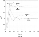
FIG. 6B shows a graph depicting variation in unit step response of the linear block with change in terrain. Further, upon substituting expression of input non-linearity shown in equation (3) in expression for the linear block output x(n), the equation (7) can be rewritten as


- In an embodiment, a non-linear function h is used to transform the output of the linear block x(n) to output of the non-linear model y(n) = v as y(n) = h(x(n)). The non-linear function h is referred as output non-linearity since it acts on the output of the linear block. This output non-linearity is configured as a saturation function in the method of proposed disclosure as shown in
FIG. 6C to model velocity saturation of the vehicle. The output non-linearity is expressed by equation (9) provided below as:
equation 10 provided below as:


- Referring back to
FIG. 3 , atstep 310, the one or more hardware processors estimate, using the generated experimental model, value of the one or more motion parameters for one or more incoming time synchronized command input signals. For example, using equation (11), velocity of the vehicle can be estimated for the one or more incoming time synchronized command input signals (e.g., velocity of the vehicle could be estimated as 1m/s for incoming time synchronized command inputs signals c 3 and c 4 for forward motion by 1 km and rotation by 1 degrees respectively) using knowledge of time synchronized command input signals stored in the generated experimental model, provided a set of model parameters expressed asK (n) = [K 1(n), K 2(n), K 3(n), K 4(n), K 5(n), K 6(n), K 7(n)] are known. - In an embodiment, the generated experimental model does not adapt to change in one or more factors such as terrain, vehicle payload, and challenging environmental conditions during real time operation. For example, it is assumed that the
system 104 of the present disclosure for indoor navigation having smooth terrain, gives value of position of the vehicle as 1km for a forward velocity of 1m/s, 2km for forward velocity of 2m/s. However, for outdoor navigation where the terrain may change, thesystem 104 may provide value of the position of the vehicle as 1km for a forward velocity of 2m/s, 2km for forward velocity of 5m/s. The generated experimental model does not adapt to change in these factors while changing from indoor navigation to outdoor navigation which may lead to inaccurate results. Thus, an Extended Kalman Filter (EKF) framework based fusion approach is implemented. The EKF framework learns about the estimation of the one or motion parameters in real time to provide an adaptive model (alternatively referred as online model) by fusing a plurality of data obtained from one or more sensors.FIG. 7 illustrates a functional block diagram of the EKF framework for estimation of the one or motion parameters in real time, in accordance with some embodiment of the present disclosure. As can be seen inFIG. 7 , the EKF framework comprises a prediction model and a measurement model. The generated experimental model is used as the prediction model which receives time synchronized command inputs signals and orientation information of the vehicle obtained from the inertial measurement unit as input and estimates position coordinates Px, Py and velocity coordinates vx, vy of the vehicle. In an embodiment, system states of the prediction model in discrete form in nth instant is defined by equation (12) provided below as:
K (n) = [K 1(n), K 2(n), K 3(n), K 4(n), K 5(n), K 6(n), K 7(n)] represents the set of model parameters of the prediction model. The discrete form of the prediction model is expressed by equation 13 provided below as:

- Referring back to
FIG. 3 , atstep 312, the one ormore hardware processors 206 perform, using a plurality of data obtained from one or more sensors, a validation of the estimated value of the one or more motion parameters. In this case, the position coordinates Px, Py and velocity coordinates vx, vy of the vehicle estimated from the prediction model of the EKF framework are referred as the one or more motion parameters. Further, the one or more sensors used for validation include position sensors and velocity sensors. In an embodiment, the step of validation is performed whenever data obtained from the one or more sensors is available. The data obtained from the one or more sensors is provided to the measurement model of the EKF framework. In an embodiment, the validation is performed by computing an error between the plurality of data obtained from the one or more sensors and measurements of the one or more motion parameters obtained from a ground truth system. For example, position data, obtained from position sensors as shown inFIG. 7 is expressed asp m = [xm , ym ] T. Further, position measurements are obtained from the ground truth system and compared with the position data obtained from position sensors. The position measurements obtained from the ground truth system are transformed to the reference frame and used as measurement updates. The measurement update is expressed in equation (15) provided below as
order 2, respectively. Further, the error computed between position data obtained from the position sensor and measurements updates of the ground truth system is expressed as (p m - H(n)z (n)). - Referring to
FIG. 3 , atstep 314, the one ormore hardware processors 206 adaptively update the experimental model to estimate an updated value of the one or more motion parameters based on the validation. For example, whenever the plurality of data from the one or more sensors is available, the error is computed. In case of no error, thesystem 104 is not required to adapt to any changes to provide accurate results. However, in presence of error, the experimental model adapts to the changes and estimates the updated value of the one or more motion parameters. The updated one or more motion parameters are further learnt and fed back to the prediction model of the EKF framework to provide continuous updates and learning ofK in the real time. In an embodiment, the step of adaptively updating the experimental model is performed using the computed error and a gain parameter as expressed in equation (16) and equation (17) provided below:

p m . The process covariance matrix provides a measure of accuracy of the prediction model. The gain parameter G(n) is computed using equation (18) provided below
p m . The noise covariance matrix provides a measure of accuracy of the plurality of data obtained from the one or more sensors. In an embodiment, the step of adaptively updating the experimental model reduces inaccuracy introduced due to the one or more factors such as change in terrain, change in payload of vehicle, and the like. - In an embodiment, the differential drive vehicle used in the system of present disclosure comprises a RGB- depth camera for position estimation using exteroceptive sensing. Additionally, a low-cost inertial measurement unit (IMU) was employed for sensing orientation of the vehicle. Further, for locomotion, one differential drive with four 6V DC motors was used in the vehicle. The DC motors were connected to a first computation system (known in the art) via a motor driver circuit. Also, a second computation system (known in the art) was mounted upon the vehicle to make it functional and an ad hoc wireless network was created to interface the first computation system and the second computation system. A known ground truth system has been used to capture actual pose of the vehicle which is used as Ground truth for experimentation. Matlab software was used for computation of the experimental model and non-linear Hammerstein-wiener model. Further, the implementation and testing was performed using ROS platform on the second computation system.
- In an embodiment, the differential drive vehicle was moved on different surfaces and trajectories. The trajectories varied from straight line to sharp turns and the velocities varied from 10 cm/sec to up to 80 cm/sec. Many experiments were performed including a variety of turning radius and frequent accelerations and decelerations, making the behavior of the vehicle highly dynamic. Motion of the vehicle remained consistent with navigation of the vehicle in real life scenarios using the method of present disclosure.
-
FIGS. 8A through 8R show graphs illustrating experimental results for control command based adaptive system and method for estimating motion parameters of differential drive vehicles, in accordance with some embodiments of the present disclosure. In an embodiment, the efficiency of the method of present disclosure is demonstrated by performing three different experiments. The three different experiments are described below: - Experiment 1: In this experiment, the vehicle was moved on a circular trajectory of varying radius, as shown in
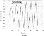
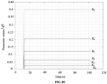
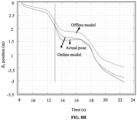
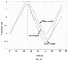
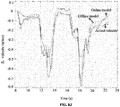
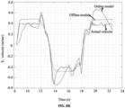
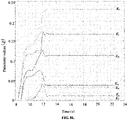
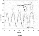
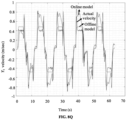
FIG. 8A .FIGS. 8B and8C illustrate graphs for estimated position along X-axis and Y-axis of reference frame respectively using the method of present disclosure with corresponding ground truth values. Here the method of present disclosure includes the generated experimental (offline) model and the adaptively updated EKF (online) model. In other words, a comparison of position computed using the offline and online model with an actual position obtained from the ground truth system is provided. As known, the online model requires measurement updates from the position sensors to estimate the set of model parametersK . The vertical line in the graphs depicted byFIGS. 8B and8C represent time instant till which measurement updates from the position sensors are sufficient to estimateK . After this time instant, no measurements were considered to be available from the position sensor. Similarly,FIGS. 8D and8E illustrate graphs for estimated velocity along X-axis and Y-axis of the reference frame respectively using the method of present disclosure with the corresponding ground truth values. In other words, a comparison of velocity computed using the offline and online model with an actual velocity obtained from the ground truth system is provided.FIG. 8F shows individual components of estimatedK using online model. For the offline model, these model parameters are computed beforehand. - Experiment 2: In this experiment, the vehicle was moved on S shape trajectory with frequent steep turns as shown in
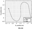
FIG. 8G . Forexperiment 2, plots of estimated position and velocity along X-axis and Y-axis of the reference frame using the method of present disclosure with the corresponding ground truth values are provided inFIGS. 8H through 8K respectively.FIG. 8L shows individual components of estimatedK using online model forexperiment 2. - Experiment 3: In this experiment, the vehicle was moved on a rectangular trajectory with steep turns as shown in
FIG. 8M . Sharp turns in trajectory makes it susceptible to slippage, which violates a no slip assumption. Forexperiment 3, plots of estimated position and velocity along X-axis and Y-axis of the reference frame using the method of present disclosure with the corresponding ground truth values are provided inFIGS. 8N through 8Q respectively.FIG. 8R shows individual components of estimatedK using online model forexperiment 3. - Table 1 provides root mean square (RMS) errors in estimated position and velocity for the three experiments using online and offline models.
Table 1 Experiment No. Position Error (m) Velocity Error (m/sec) Model X1 Y1 X1 Y1 1 0.1272 0.1404 0.0286 0.0295 Online 2 0.0746 0.2280 0.0690 0.1456 3 0.3976 0.1048 0.1048 0.1860 1 0.2654 0.2001 0.0454 0.0467 Offline 2 0.3151 0.3508 0.0989 0.1031 3 0.5605 0.3532 0.1418 0.1412 - Offline model: For this model, the set of model parameters (
K ) for all the three experiments were computed beforehand. The RMS errors for all the experiments are presented in Table 1. It is evident from the Table 1 that for the trajectories similar toexperiments experiment 3, which violates no slip assumption because of sharp turns, the position and velocity error are relatively higher, but still below 1 m and 0.2 m/sec respectively. - Online model: For this model, the set model parameters (
K ) were computed in real time, and no prior information was available. The EKF framework used measurement updates from position sensor to computeK , wherein these updates were required by the method of present disclosure only during the initial period of the experiment for computation. The vertical line inFIGS. 8B through 8D forexperiment 1,FIGS. 8H through 8K forexperiment 2, andFIGS. 8N through 8Q forexperiment 3 show time instant till which position updates have been used to computeK , andFIGS. 8F forexperiment 1, 8L forexperiment 2, and 8R forexperiment 3 show howK evolves over time during experiments. As can be seen from Table 1, the errors for position and velocity estimation are contained well below 1 m and 0.2 m/sec, almost similar to offline model. - The method of the present disclosure provides accurate results for localization or estimating the motion parameters of the differential drive vehicle with minimum use of extroceptive sensors. Reduction in the number of sensors leads to reduced cost. Also, the system of the present disclosure adapts to change in different factors such as terrain, payload change, and the like by continuous learning.
- The illustrated steps of
method 300 is set out to explain the exemplary embodiments shown, and it should be anticipated that ongoing technological development may change the manner in which particular functions are performed. These examples are presented herein for purposes of illustration, and not limitation. - The written description describes the subject matter herein to enable any person skilled in the art to make and use the embodiments. The scope of the subject matter embodiments is defined by the claims and may include other modifications that occur to those skilled in the art. Such other modifications are intended to be within the scope of the claims.
- It is to be understood that the scope of the protection is extended to such a program and in addition to a computer-readable means having a message therein; such computer-readable storage means contain program-code means for implementation of one or more steps of the method, when the program runs on a server or mobile device or any suitable programmable device. The hardware device can be any kind of device which can be programmed including e.g. any kind of computer like a server or a personal computer, or the like, or any combination thereof. The device may also include means which could be e.g. hardware means like e.g. an applicationspecific integrated circuit (ASIC), a field-programmable gate array (FPGA), or a combination of hardware and software means, e.g. an ASIC and an FPGA, or at least one microprocessor and at least one memory with software modules located therein. Thus, the means can include both hardware means and software means. The method embodiments described herein could be implemented in hardware and software. The device may also include software means. Alternatively, the embodiments may be implemented on different hardware devices, e.g. using a plurality of CPUs.
- The embodiments herein can comprise hardware and software elements. The embodiments that are implemented in software include but are not limited to, firmware, resident software, microcode, etc. The functions performed by various modules described herein may be implemented in other modules or combinations of other modules. For the purposes of this description, a computer-usable or computer readable medium can be any apparatus that can comprise, store, communicate, propagate, or transport the program for use by or in connection with the instruction execution system, apparatus, or device.
- The illustrated steps are set out to explain the exemplary embodiments shown, and it should be anticipated that ongoing technological development will change the manner in which particular functions are performed. These examples are presented herein for purposes of illustration, and not limitation. Further, the boundaries of the functional building blocks have been arbitrarily defined herein for the convenience of the description. Alternative boundaries can be defined so long as the specified functions and relationships thereof are appropriately performed. Alternatives (including equivalents, extensions, variations, deviations, etc., of those described herein) will be apparent to persons skilled in the relevant art(s) based on the teachings contained herein. Such alternatives will always be considered as long as they are within the scope of the invention as defined by the apended claims.
- Furthermore, one or more computer-readable storage media may be utilized in implementing embodiments consistent with the present disclosure. A computer-readable storage medium refers to any type of physical memory on which information or data readable by a processor may be stored. Thus, a computer-readable storage medium may store instructions for execution by one or more processors, including instructions for causing the processor(s) to perform steps or stages consistent with the embodiments described herein. The term "computer-readable medium" should be understood to include tangible items and exclude carrier waves and transient signals, i.e., be non-transitory. Examples include random access memory (RAM), read-only memory (ROM), volatile memory, nonvolatile memory, hard drives, CD ROMs, DVDs, flash drives, disks, and any other known physical storage media.
- It is intended that the disclosure and examples be considered as exemplary only, with the invention being defined by the following claims.
Claims (12)
- A processor implemented method, comprising:inputting (302), via the one or more hardware processors, one or more time synchronized command input signals to a moving differential drive vehicle;determining (304), based on the one or more time synchronized command input signals, a corresponding change in one or more motion parameters of the moving differential drive vehicle;training (306) a non-linear model using the one or more time synchronized command input signals and the determined corresponding change in the one or more motion parameters, wherein the non-linear model is a Hammerstein-Wiener model comprising a static input non-linearity block, a dynamic linear block, and a static output non-linearity block, in series, wherein the static input non-linearity block captures nonlinearity behavior present in the one or more time synchronized command input signals, wherein the dynamic linear block captures dynamic response of the Hammerstein-Weiner model, and wherein the static output non-linearity block captures non-linearity present in the dynamic response of the Hammerstein-Weiner model;generating (308), using the trained non-linear model, an experimental model by computing a mapping function between the one or more time synchronized command input signals and the one or more motion parameters of the moving differential drive vehicle, wherein the one or more motion parameters comprises position coordinates and velocity coordinates of the moving differential drive vehicle;estimating (310), using the generated experimental model, value of the one or more motion parameters based on the one or more incoming time synchronized command input signals and orientation information obtained from an inertial measurement unit of the moving differential drive vehicle;performing (312), using a plurality of data obtained from one or more sensors, a validation of the estimated value of the one or more motion parameters; andadaptively updating (314) the experimental model to estimate an updated value of the one or more motion parameters based on the validation, by learning model parameters in real time.
- The processor implemented method according to claim 1, wherein the one or more sensors used for validation include position sensors and velocity sensors.
- The processor implemented method according to claim 1, wherein the validation is performed by computing an error between the plurality of data obtained from the one or more sensors and measurements of one or more motion parameters obtained from a ground truth system.
- The processor implemented method according to claim 1, wherein the step of adaptively updating the experimental model is performed using the computed error and a gain parameter.
- A system (104), comprising:a memory (202);one or more communication interfaces (204); andone or more hardware processors (206) coupled to said memory (202) through said one or more communication interfaces (204), wherein said one or more hardware processors (206) are configured to:input one or more time synchronized command input signals to a moving differential drive vehicle;determine, based on the one or more time synchronized command input signals, a corresponding change in one or more motion parameters of the moving differential drive vehicle;train a non-linear model using the one or more time synchronized command input signals and the determined corresponding change in the one or more motion parameters, wherein the non-linear model is a Hammerstein-Wiener model comprising a static input non-linearity block, a dynamic linear block, and a static output non-linearity block, in series, wherein the static input non-linearity block captures non-linearity behavior present in the one or more time synchronized command input signals, wherein the dynamic linear block captures dynamic response of the Hammerstein-Weiner model, and wherein the static output non-linearity block captures non-linearity present in the dynamic response of the Hammerstein-Weiner model;generate, using the trained non-linear model, an experimental model by computing a mapping function between the one or more time synchronized command input signals and the one or more motion parameters of the moving differential drive vehicle, wherein the one or more motion parameters comprises position coordinates and velocity coordinates of the moving differential drive vehicle;estimate, using the generated experimental model, value of the one or more motion parameters based on the one or more incoming time synchronized command input signals and orientation information obtained from an inertial measurement unit of the moving differential drive vehicle;perform, using a plurality of data obtained from one or more sensors, a validation of the estimated value of the one or more motion parameters; andadaptively update the experimental model to estimate an updated value of the one or more motion parameters based on the validation, by learning model parameters in real time.
- The system according to claim 5, wherein the one or more sensors used for validation include position sensors and velocity sensors.
- The system according to claim 5, wherein the validation is performed by computing an error between the plurality of data obtained from the one or more sensors and measurements of one or more motion parameters obtained from a ground truth system.
- The system according to claim 5, wherein the step of adaptively updating the experimental model is performed using the computed error and a gain parameter.
- One or more non-transitory machine-readable information storage mediums comprising one or more instructions which when executed by one or more hardware processors cause:inputting, via the one or more hardware processors, one or more time synchronized command input signals to a moving differential drive vehicle;determining, based on the one or more time synchronized command input signals, a corresponding change in one or more motion parameters of the moving differential drive vehicle;training a non-linear model using the one or more time synchronized command input signals and the determined corresponding change in the one or more motion parameters, wherein the non-linear model is a Hammerstein-Wiener model comprising a static input non-linearity block, a dynamic linear block, and a static output nonlinearity block, in series, wherein the static input non-linearity block captures nonlinearity behavior present in the one or more time synchronized command input signals, wherein the dynamic linear block captures dynamic response of the Hammerstein-Weiner model, and wherein the static output non-linearity block captures non-linearity present in the dynamic response of the Hammerstein-Weiner model;generating, using the trained non-linear model, an experimental model by computing a mapping function between the one or more time synchronized command input signals and the one or more motion parameters of the moving differential drive vehicle, wherein the one or more motion parameters comprises position coordinates and velocity coordinates of the moving differential drive vehicle;estimating, using the generated experimental model, value of the one or more motion parameters based on the one or more incoming time synchronized command input signals and orientation information obtained from an inertial measurement unit of the moving differential drive vehicle;performing, using a plurality of data obtained from one or more sensors, a validation of the estimated value of the one or more motion parameters; andadaptively updating the experimental model to estimate an updated value of the one or more motion parameters based on the validation, by learning model parameters in real time.
- The one or more non-transitory machine-readable information storage mediums according to claim 9, wherein the one or more sensors used for validation include position sensors and velocity sensors.
- The one or more non-transitory machine-readable information storage mediums according to claim 9, wherein the validation is performed by computing an error between the plurality of data obtained from the one or more sensors and measurements of one or more motion parameters obtained from a ground truth system.
- The one or more non-transitory machine-readable information storage mediums according to claim 9, wherein the step of adaptively updating the experimental model is performed using the computed error and a gain parameter.
Applications Claiming Priority (1)
| Application Number | Priority Date | Filing Date | Title |
|---|---|---|---|
| IN201921039285 | 2019-09-27 |
Publications (2)
| Publication Number | Publication Date |
|---|---|
| EP3797939A1 EP3797939A1 (en) | 2021-03-31 |
| EP3797939B1 true EP3797939B1 (en) | 2023-03-01 |
Family
ID=72148001
Family Applications (1)
| Application Number | Title | Priority Date | Filing Date |
|---|---|---|---|
| EP20191743.2A Active EP3797939B1 (en) | 2019-09-27 | 2020-08-19 | Control command based adaptive system and method for estimating motion parameters of differential drive vehicles |
Country Status (1)
| Country | Link |
|---|---|
| EP (1) | EP3797939B1 (en) |
-
2020
- 2020-08-19 EP EP20191743.2A patent/EP3797939B1/en active Active
Also Published As
| Publication number | Publication date |
|---|---|
| EP3797939A1 (en) | 2021-03-31 |
| US20210097437A1 (en) | 2021-04-01 |
Similar Documents
| Publication | Publication Date | Title |
|---|---|---|
| EP3940421A1 (en) | Positioning method and device based on multi-sensor fusion | |
| Paden et al. | A survey of motion planning and control techniques for self-driving urban vehicles | |
| Klančar et al. | A control strategy for platoons of differential drive wheeled mobile robot | |
| Cheein et al. | Trajectory tracking controller design for unmanned vehicles: A new methodology | |
| Marin et al. | Event-based localization in ackermann steering limited resource mobile robots | |
| Erfani et al. | Comparison of two data fusion methods for localization of wheeled mobile robot in farm conditions | |
| Sebastian et al. | Active disturbance rejection control for handling slip in tracked vehicle locomotion | |
| Taghia et al. | A sliding mode controller with a nonlinear disturbance observer for a farm vehicle operating in the presence of wheel slip | |
| Coelho et al. | Ekf and computer vision for mobile robot localization | |
| Assad et al. | Novel adaptive fuzzy extended Kalman filter for attitude estimation in GPS-denied environment | |
| Mellah et al. | Health state monitoring of 4-mecanum wheeled mobile robot actuators and its impact on the robot behavior analysis | |
| EP3797939B1 (en) | Control command based adaptive system and method for estimating motion parameters of differential drive vehicles | |
| Ljungqvist | On motion planning and control for truck and trailer systems | |
| Ismael et al. | Nonlinear Model Predictive Control-based Collision Avoidance for Mobile Robot | |
| US11958194B2 (en) | Control command based adaptive system and method for estimating motion parameters of differential drive vehicles | |
| Pentzer et al. | On‐line estimation of power model parameters for skid‐steer robots with applications in mission energy use prediction | |
| Biswas et al. | Validating observer based on-line slip estimation for improved navigation by a mobile robot | |
| Temeltas | A Real-Time Localization Method For Agvs In Smart Factories | |
| Chatterjee et al. | Cooperative curve tracking in two dimensions without explicit estimation of the field gradient | |
| Hidalgo et al. | Kinematics modeling of a hybrid wheeled-leg planetary rover | |
| Jaroszek et al. | Localization of the wheeled mobile robot based on multi-sensor data fusion | |
| Macias et al. | Single landmark feedback-based time optimal navigation for a differential drive robot | |
| Oonk et al. | Extended kalman filter for improved navigation with fault awareness | |
| Pazderski et al. | A unified motion control and low level planning algorithm for a wheeled skid-steering robot | |
| Jeevan et al. | Implementation and Design of Agile and Multipurpose Autonomous Robot Using ROS |
Legal Events
| Date | Code | Title | Description |
|---|---|---|---|
| PUAI | Public reference made under article 153(3) epc to a published international application that has entered the european phase |
Free format text: ORIGINAL CODE: 0009012 |
|
| STAA | Information on the status of an ep patent application or granted ep patent |
Free format text: STATUS: THE APPLICATION HAS BEEN PUBLISHED |
|
| AK | Designated contracting states |
Kind code of ref document: A1 Designated state(s): AL AT BE BG CH CY CZ DE DK EE ES FI FR GB GR HR HU IE IS IT LI LT LU LV MC MK MT NL NO PL PT RO RS SE SI SK SM TR |
|
| AX | Request for extension of the european patent |
Extension state: BA ME |
|
| STAA | Information on the status of an ep patent application or granted ep patent |
Free format text: STATUS: REQUEST FOR EXAMINATION WAS MADE |
|
| 17P | Request for examination filed |
Effective date: 20210930 |
|
| RBV | Designated contracting states (corrected) |
Designated state(s): AL AT BE BG CH CY CZ DE DK EE ES FI FR GB GR HR HU IE IS IT LI LT LU LV MC MK MT NL NO PL PT RO RS SE SI SK SM TR |
|
| RIC1 | Information provided on ipc code assigned before grant |
Ipc: G05D 1/02 20200101ALI20220719BHEP Ipc: B25J 9/16 20060101AFI20220719BHEP |
|
| GRAP | Despatch of communication of intention to grant a patent |
Free format text: ORIGINAL CODE: EPIDOSNIGR1 |
|
| STAA | Information on the status of an ep patent application or granted ep patent |
Free format text: STATUS: GRANT OF PATENT IS INTENDED |
|
| INTG | Intention to grant announced |
Effective date: 20220919 |
|
| GRAS | Grant fee paid |
Free format text: ORIGINAL CODE: EPIDOSNIGR3 |
|
| GRAA | (expected) grant |
Free format text: ORIGINAL CODE: 0009210 |
|
| STAA | Information on the status of an ep patent application or granted ep patent |
Free format text: STATUS: THE PATENT HAS BEEN GRANTED |
|
| AK | Designated contracting states |
Kind code of ref document: B1 Designated state(s): AL AT BE BG CH CY CZ DE DK EE ES FI FR GB GR HR HU IE IS IT LI LT LU LV MC MK MT NL NO PL PT RO RS SE SI SK SM TR |
|
| REG | Reference to a national code |
Ref country code: GB Ref legal event code: FG4D |
|
| REG | Reference to a national code |
Ref country code: CH Ref legal event code: EP Ref country code: AT Ref legal event code: REF Ref document number: 1550659 Country of ref document: AT Kind code of ref document: T Effective date: 20230315 |
|
| REG | Reference to a national code |
Ref country code: DE Ref legal event code: R096 Ref document number: 602020008417 Country of ref document: DE |
|
| REG | Reference to a national code |
Ref country code: IE Ref legal event code: FG4D |
|
| REG | Reference to a national code |
Ref country code: NL Ref legal event code: FP |
|
| REG | Reference to a national code |
Ref country code: LT Ref legal event code: MG9D |
|
| P01 | Opt-out of the competence of the unified patent court (upc) registered |
Effective date: 20230526 |
|
| PG25 | Lapsed in a contracting state [announced via postgrant information from national office to epo] |
Ref country code: RS Free format text: LAPSE BECAUSE OF FAILURE TO SUBMIT A TRANSLATION OF THE DESCRIPTION OR TO PAY THE FEE WITHIN THE PRESCRIBED TIME-LIMIT Effective date: 20230301 Ref country code: NO Free format text: LAPSE BECAUSE OF FAILURE TO SUBMIT A TRANSLATION OF THE DESCRIPTION OR TO PAY THE FEE WITHIN THE PRESCRIBED TIME-LIMIT Effective date: 20230601 Ref country code: LV Free format text: LAPSE BECAUSE OF FAILURE TO SUBMIT A TRANSLATION OF THE DESCRIPTION OR TO PAY THE FEE WITHIN THE PRESCRIBED TIME-LIMIT Effective date: 20230301 Ref country code: LT Free format text: LAPSE BECAUSE OF FAILURE TO SUBMIT A TRANSLATION OF THE DESCRIPTION OR TO PAY THE FEE WITHIN THE PRESCRIBED TIME-LIMIT Effective date: 20230301 Ref country code: HR Free format text: LAPSE BECAUSE OF FAILURE TO SUBMIT A TRANSLATION OF THE DESCRIPTION OR TO PAY THE FEE WITHIN THE PRESCRIBED TIME-LIMIT Effective date: 20230301 Ref country code: ES Free format text: LAPSE BECAUSE OF FAILURE TO SUBMIT A TRANSLATION OF THE DESCRIPTION OR TO PAY THE FEE WITHIN THE PRESCRIBED TIME-LIMIT Effective date: 20230301 |
|
| REG | Reference to a national code |
Ref country code: AT Ref legal event code: MK05 Ref document number: 1550659 Country of ref document: AT Kind code of ref document: T Effective date: 20230301 |
|
| PG25 | Lapsed in a contracting state [announced via postgrant information from national office to epo] |
Ref country code: SE Free format text: LAPSE BECAUSE OF FAILURE TO SUBMIT A TRANSLATION OF THE DESCRIPTION OR TO PAY THE FEE WITHIN THE PRESCRIBED TIME-LIMIT Effective date: 20230301 Ref country code: PL Free format text: LAPSE BECAUSE OF FAILURE TO SUBMIT A TRANSLATION OF THE DESCRIPTION OR TO PAY THE FEE WITHIN THE PRESCRIBED TIME-LIMIT Effective date: 20230301 Ref country code: GR Free format text: LAPSE BECAUSE OF FAILURE TO SUBMIT A TRANSLATION OF THE DESCRIPTION OR TO PAY THE FEE WITHIN THE PRESCRIBED TIME-LIMIT Effective date: 20230602 Ref country code: FI Free format text: LAPSE BECAUSE OF FAILURE TO SUBMIT A TRANSLATION OF THE DESCRIPTION OR TO PAY THE FEE WITHIN THE PRESCRIBED TIME-LIMIT Effective date: 20230301 |
|
| PGFP | Annual fee paid to national office [announced via postgrant information from national office to epo] |
Ref country code: NL Payment date: 20230825 Year of fee payment: 4 |
|
| PG25 | Lapsed in a contracting state [announced via postgrant information from national office to epo] |
Ref country code: SM Free format text: LAPSE BECAUSE OF FAILURE TO SUBMIT A TRANSLATION OF THE DESCRIPTION OR TO PAY THE FEE WITHIN THE PRESCRIBED TIME-LIMIT Effective date: 20230301 Ref country code: RO Free format text: LAPSE BECAUSE OF FAILURE TO SUBMIT A TRANSLATION OF THE DESCRIPTION OR TO PAY THE FEE WITHIN THE PRESCRIBED TIME-LIMIT Effective date: 20230301 Ref country code: PT Free format text: LAPSE BECAUSE OF FAILURE TO SUBMIT A TRANSLATION OF THE DESCRIPTION OR TO PAY THE FEE WITHIN THE PRESCRIBED TIME-LIMIT Effective date: 20230703 Ref country code: EE Free format text: LAPSE BECAUSE OF FAILURE TO SUBMIT A TRANSLATION OF THE DESCRIPTION OR TO PAY THE FEE WITHIN THE PRESCRIBED TIME-LIMIT Effective date: 20230301 Ref country code: CZ Free format text: LAPSE BECAUSE OF FAILURE TO SUBMIT A TRANSLATION OF THE DESCRIPTION OR TO PAY THE FEE WITHIN THE PRESCRIBED TIME-LIMIT Effective date: 20230301 Ref country code: AT Free format text: LAPSE BECAUSE OF FAILURE TO SUBMIT A TRANSLATION OF THE DESCRIPTION OR TO PAY THE FEE WITHIN THE PRESCRIBED TIME-LIMIT Effective date: 20230301 |
|
| PGFP | Annual fee paid to national office [announced via postgrant information from national office to epo] |
Ref country code: CH Payment date: 20230902 Year of fee payment: 4 |
|
| PG25 | Lapsed in a contracting state [announced via postgrant information from national office to epo] |
Ref country code: SK Free format text: LAPSE BECAUSE OF FAILURE TO SUBMIT A TRANSLATION OF THE DESCRIPTION OR TO PAY THE FEE WITHIN THE PRESCRIBED TIME-LIMIT Effective date: 20230301 Ref country code: IS Free format text: LAPSE BECAUSE OF FAILURE TO SUBMIT A TRANSLATION OF THE DESCRIPTION OR TO PAY THE FEE WITHIN THE PRESCRIBED TIME-LIMIT Effective date: 20230701 |
|
| PGFP | Annual fee paid to national office [announced via postgrant information from national office to epo] |
Ref country code: FR Payment date: 20230824 Year of fee payment: 4 Ref country code: DE Payment date: 20230828 Year of fee payment: 4 |
|
| REG | Reference to a national code |
Ref country code: DE Ref legal event code: R097 Ref document number: 602020008417 Country of ref document: DE |
|
| PLBE | No opposition filed within time limit |
Free format text: ORIGINAL CODE: 0009261 |
|
| STAA | Information on the status of an ep patent application or granted ep patent |
Free format text: STATUS: NO OPPOSITION FILED WITHIN TIME LIMIT |
|
| PG25 | Lapsed in a contracting state [announced via postgrant information from national office to epo] |
Ref country code: SI Free format text: LAPSE BECAUSE OF FAILURE TO SUBMIT A TRANSLATION OF THE DESCRIPTION OR TO PAY THE FEE WITHIN THE PRESCRIBED TIME-LIMIT Effective date: 20230301 Ref country code: DK Free format text: LAPSE BECAUSE OF FAILURE TO SUBMIT A TRANSLATION OF THE DESCRIPTION OR TO PAY THE FEE WITHIN THE PRESCRIBED TIME-LIMIT Effective date: 20230301 |
|
| 26N | No opposition filed |
Effective date: 20231204 |
|
| PG25 | Lapsed in a contracting state [announced via postgrant information from national office to epo] |
Ref country code: MC Free format text: LAPSE BECAUSE OF FAILURE TO SUBMIT A TRANSLATION OF THE DESCRIPTION OR TO PAY THE FEE WITHIN THE PRESCRIBED TIME-LIMIT Effective date: 20230301 |
|
| PG25 | Lapsed in a contracting state [announced via postgrant information from national office to epo] |
Ref country code: MC Free format text: LAPSE BECAUSE OF FAILURE TO SUBMIT A TRANSLATION OF THE DESCRIPTION OR TO PAY THE FEE WITHIN THE PRESCRIBED TIME-LIMIT Effective date: 20230301 |