EP3796812B1 - Appliance hinge assembly - Google Patents
Appliance hinge assembly Download PDFInfo
- Publication number
- EP3796812B1 EP3796812B1 EP18920164.3A EP18920164A EP3796812B1 EP 3796812 B1 EP3796812 B1 EP 3796812B1 EP 18920164 A EP18920164 A EP 18920164A EP 3796812 B1 EP3796812 B1 EP 3796812B1
- Authority
- EP
- European Patent Office
- Prior art keywords
- hinge
- wrapper
- refrigerator
- trim breaker
- cabinet structure
- Prior art date
- Legal status (The legal status is an assumption and is not a legal conclusion. Google has not performed a legal analysis and makes no representation as to the accuracy of the status listed.)
- Active
Links
- 238000009413 insulation Methods 0.000 claims description 26
- 238000005538 encapsulation Methods 0.000 description 24
- 239000000463 material Substances 0.000 description 20
- 239000007789 gas Substances 0.000 description 8
- 238000000034 method Methods 0.000 description 8
- 239000002861 polymer material Substances 0.000 description 8
- 230000008569 process Effects 0.000 description 8
- IJGRMHOSHXDMSA-UHFFFAOYSA-N Atomic nitrogen Chemical compound N#N IJGRMHOSHXDMSA-UHFFFAOYSA-N 0.000 description 6
- CURLTUGMZLYLDI-UHFFFAOYSA-N Carbon dioxide Chemical compound O=C=O CURLTUGMZLYLDI-UHFFFAOYSA-N 0.000 description 6
- 230000004888 barrier function Effects 0.000 description 6
- 229920000642 polymer Polymers 0.000 description 5
- 239000011162 core material Substances 0.000 description 4
- 230000008878 coupling Effects 0.000 description 4
- 238000010168 coupling process Methods 0.000 description 4
- 238000005859 coupling reaction Methods 0.000 description 4
- 239000002184 metal Substances 0.000 description 4
- 239000007769 metal material Substances 0.000 description 4
- QVGXLLKOCUKJST-UHFFFAOYSA-N atomic oxygen Chemical compound [O] QVGXLLKOCUKJST-UHFFFAOYSA-N 0.000 description 3
- 229910002092 carbon dioxide Inorganic materials 0.000 description 3
- 239000001569 carbon dioxide Substances 0.000 description 3
- 238000001816 cooling Methods 0.000 description 3
- 229920001971 elastomer Polymers 0.000 description 3
- 239000000806 elastomer Substances 0.000 description 3
- 230000007246 mechanism Effects 0.000 description 3
- 229910052757 nitrogen Inorganic materials 0.000 description 3
- 239000001301 oxygen Substances 0.000 description 3
- 229910052760 oxygen Inorganic materials 0.000 description 3
- 238000010107 reaction injection moulding Methods 0.000 description 3
- 230000002787 reinforcement Effects 0.000 description 3
- 238000003856 thermoforming Methods 0.000 description 3
- XLYOFNOQVPJJNP-UHFFFAOYSA-N water Chemical compound O XLYOFNOQVPJJNP-UHFFFAOYSA-N 0.000 description 3
- VYPSYNLAJGMNEJ-UHFFFAOYSA-N Silicium dioxide Chemical compound O=[Si]=O VYPSYNLAJGMNEJ-UHFFFAOYSA-N 0.000 description 2
- 239000002131 composite material Substances 0.000 description 2
- 239000011810 insulating material Substances 0.000 description 2
- 230000033001 locomotion Effects 0.000 description 2
- 230000003014 reinforcing effect Effects 0.000 description 2
- 229920001169 thermoplastic Polymers 0.000 description 2
- 239000004677 Nylon Substances 0.000 description 1
- 229920002396 Polyurea Polymers 0.000 description 1
- 230000000712 assembly Effects 0.000 description 1
- 238000000429 assembly Methods 0.000 description 1
- 230000005540 biological transmission Effects 0.000 description 1
- 239000011248 coating agent Substances 0.000 description 1
- 238000000576 coating method Methods 0.000 description 1
- 230000000295 complement effect Effects 0.000 description 1
- 230000007423 decrease Effects 0.000 description 1
- 239000013536 elastomeric material Substances 0.000 description 1
- 239000000945 filler Substances 0.000 description 1
- 238000003197 gene knockdown Methods 0.000 description 1
- 238000001746 injection moulding Methods 0.000 description 1
- 238000003780 insertion Methods 0.000 description 1
- 230000037431 insertion Effects 0.000 description 1
- 238000000465 moulding Methods 0.000 description 1
- 229920001778 nylon Polymers 0.000 description 1
- 229920000515 polycarbonate Polymers 0.000 description 1
- 239000004417 polycarbonate Substances 0.000 description 1
- 229920000647 polyepoxide Polymers 0.000 description 1
- 229920000728 polyester Polymers 0.000 description 1
- 229920000582 polyisocyanurate Polymers 0.000 description 1
- 150000008442 polyphenolic compounds Chemical class 0.000 description 1
- 235000013824 polyphenols Nutrition 0.000 description 1
- 229920002635 polyurethane Polymers 0.000 description 1
- 239000004814 polyurethane Substances 0.000 description 1
- 239000000843 powder Substances 0.000 description 1
- 238000007789 sealing Methods 0.000 description 1
- 239000000377 silicon dioxide Substances 0.000 description 1
- 239000000243 solution Substances 0.000 description 1
- 229920002725 thermoplastic elastomer Polymers 0.000 description 1
- 210000002105 tongue Anatomy 0.000 description 1
Images


Classifications
-
- F—MECHANICAL ENGINEERING; LIGHTING; HEATING; WEAPONS; BLASTING
- F25—REFRIGERATION OR COOLING; COMBINED HEATING AND REFRIGERATION SYSTEMS; HEAT PUMP SYSTEMS; MANUFACTURE OR STORAGE OF ICE; LIQUEFACTION SOLIDIFICATION OF GASES
- F25D—REFRIGERATORS; COLD ROOMS; ICE-BOXES; COOLING OR FREEZING APPARATUS NOT OTHERWISE PROVIDED FOR
- F25D23/00—General constructional features
- F25D23/02—Doors; Covers
- F25D23/028—Details
-
- F—MECHANICAL ENGINEERING; LIGHTING; HEATING; WEAPONS; BLASTING
- F25—REFRIGERATION OR COOLING; COMBINED HEATING AND REFRIGERATION SYSTEMS; HEAT PUMP SYSTEMS; MANUFACTURE OR STORAGE OF ICE; LIQUEFACTION SOLIDIFICATION OF GASES
- F25D—REFRIGERATORS; COLD ROOMS; ICE-BOXES; COOLING OR FREEZING APPARATUS NOT OTHERWISE PROVIDED FOR
- F25D23/00—General constructional features
- F25D23/06—Walls
- F25D23/065—Details
-
- F—MECHANICAL ENGINEERING; LIGHTING; HEATING; WEAPONS; BLASTING
- F25—REFRIGERATION OR COOLING; COMBINED HEATING AND REFRIGERATION SYSTEMS; HEAT PUMP SYSTEMS; MANUFACTURE OR STORAGE OF ICE; LIQUEFACTION SOLIDIFICATION OF GASES
- F25D—REFRIGERATORS; COLD ROOMS; ICE-BOXES; COOLING OR FREEZING APPARATUS NOT OTHERWISE PROVIDED FOR
- F25D23/00—General constructional features
- F25D23/06—Walls
- F25D23/062—Walls defining a cabinet
-
- F—MECHANICAL ENGINEERING; LIGHTING; HEATING; WEAPONS; BLASTING
- F25—REFRIGERATION OR COOLING; COMBINED HEATING AND REFRIGERATION SYSTEMS; HEAT PUMP SYSTEMS; MANUFACTURE OR STORAGE OF ICE; LIQUEFACTION SOLIDIFICATION OF GASES
- F25D—REFRIGERATORS; COLD ROOMS; ICE-BOXES; COOLING OR FREEZING APPARATUS NOT OTHERWISE PROVIDED FOR
- F25D23/00—General constructional features
- F25D23/08—Parts formed wholly or mainly of plastics materials
- F25D23/082—Strips
- F25D23/085—Breaking strips
-
- E—FIXED CONSTRUCTIONS
- E05—LOCKS; KEYS; WINDOW OR DOOR FITTINGS; SAFES
- E05Y—INDEXING SCHEME RELATING TO HINGES OR OTHER SUSPENSION DEVICES FOR DOORS, WINDOWS OR WINGS AND DEVICES FOR MOVING WINGS INTO OPEN OR CLOSED POSITION, CHECKS FOR WINGS AND WING FITTINGS NOT OTHERWISE PROVIDED FOR, CONCERNED WITH THE FUNCTIONING OF THE WING
- E05Y2900/00—Application of doors, windows, wings or fittings thereof
- E05Y2900/30—Application of doors, windows, wings or fittings thereof for domestic appliances
- E05Y2900/31—Application of doors, windows, wings or fittings thereof for domestic appliances for refrigerators
-
- F—MECHANICAL ENGINEERING; LIGHTING; HEATING; WEAPONS; BLASTING
- F25—REFRIGERATION OR COOLING; COMBINED HEATING AND REFRIGERATION SYSTEMS; HEAT PUMP SYSTEMS; MANUFACTURE OR STORAGE OF ICE; LIQUEFACTION SOLIDIFICATION OF GASES
- F25D—REFRIGERATORS; COLD ROOMS; ICE-BOXES; COOLING OR FREEZING APPARATUS NOT OTHERWISE PROVIDED FOR
- F25D2323/00—General constructional features not provided for in other groups of this subclass
- F25D2323/02—Details of doors or covers not otherwise covered
- F25D2323/021—French doors
-
- F—MECHANICAL ENGINEERING; LIGHTING; HEATING; WEAPONS; BLASTING
- F25—REFRIGERATION OR COOLING; COMBINED HEATING AND REFRIGERATION SYSTEMS; HEAT PUMP SYSTEMS; MANUFACTURE OR STORAGE OF ICE; LIQUEFACTION SOLIDIFICATION OF GASES
- F25D—REFRIGERATORS; COLD ROOMS; ICE-BOXES; COOLING OR FREEZING APPARATUS NOT OTHERWISE PROVIDED FOR
- F25D2323/00—General constructional features not provided for in other groups of this subclass
- F25D2323/02—Details of doors or covers not otherwise covered
- F25D2323/024—Door hinges
Definitions
- the present device generally relates to insulated structures, in particular, to a vacuum insulated refrigerator cabinet structure that includes a door hinge bracket coupled thereto.
- Document US 2,065,608 discloses an insulating container in the form of a hermetically closed compartment formed between an outer vessel and an inner vessel, the front edges of the vessels being connected by a hermetically sealed wall.
- the casing encloses an insulating element.
- a wooden frame is fastened to the front of the casing to give the necessary strength to the casing and to provide means for attaching the hinges of the door.
- Document US 1,948,587 discloses a knock-down refrigerator cabinet comprising a plurality of walls, each wall including inner and outer spaced metal plates and insulating material between the plates.
- Document US Re. 21,364 discloses a refrigerator having spaced inner and outer metallic walls provided with a door opening, a door in the opening having spaced inner and outer metallic walls, a pair of non-heat conducting elastic breaker and sealing strips disposed in interengaging locking relation with the spaced walls of the cabinet and door, respectively, and covering the space between the respective inner and outer walls, the cabinet and door strips having opposed abutting surfaces adapted when the door is in closed position to cooperate in forming a seal between the cabinet and door.
- a refrigerator 10 includes a cabinet structure 12 having a wrapper 14 defining an opening 16. At least one liner 18, 20 is positioned inside the opening 16 of the wrapper 14 and defines at least one temperature-controlled compartment 48, 50. An insulation cavity 22 is defined between the wrapper 14 and the liner 18, 20.
- a trim breaker 24 is coupled to the wrapper 14 and the liner 18, 20.
- a first hinge bracket 26 is positioned outwardly of the trim breaker 24.
- An encapsulation member 28 is positioned rearwardly of the trim breaker 24 and defines an encapsulation cavity 30.
- a first hinge support 32 has a first section 34 positioned along a second hinge support 36 and a second section 38 extending rearwardly of the first section 34.
- the first hinge bracket 26 is operably coupled with the first and second hinge supports 32, 36.
- a second hinge bracket 40 may be positioned on an opposing side of a temperature-controlled compartment 48, 50.
- a second hinge bracket 40 may be operably coupled with an externally positioned brace 42.
- the brace 42 may be fixed to a plate 44.
- the plate 44 extends laterally across an exterior portion 46 of the wrapper 14.
- the refrigerator 10 includes the insulated cabinet structure 12 that may define the temperature-controlled compartment 48, 50, such as a refrigerator compartment 48 and/or a freezer compartment 50.
- One or more refrigerator compartment doors 52, 54 are provided to selectively provide access to the refrigerator compartment 48, while one or more freezer compartment doors 56 may be used to provide access to the freezer compartment 50.
- the configuration of the refrigerator 10 illustrated in FIG. 1 is exemplary only and the present concept is contemplated for use in all refrigerator styles including, but not limited to, side-by-side refrigerators, whole refrigerator and freezers, and refrigerators with upper freezer compartments.
- the one or more refrigerator compartment doors 52, 54 and/or one or more freezer compartment doors 56 may be hingedly attached to the cabinet structure 12 and/or slidably attached to the cabinet structure 12 without departing from the teachings provided herein. It will also be appreciated that the assemblies provided herein may be used in any other appliance and/or cabinet structure 12 without departing from the scope of the present disclosure.
- the insulated cabinet structure 12 also includes the trim breaker 24 that includes an upper portion 58, a central portion 60, and a lower portion 62.
- the refrigerator liner 18 has a top wall 64, bottom wall 66, opposed sidewalls 68, 70, and a rear wall 72 which cooperate to define the refrigerator compartment 48.
- the refrigerator liner 18 further includes a front edge portion 74 positioned on a front portion of the refrigerator compartment 48.
- the freezer liner 20 includes a top wall 76, a bottom wall 78, opposed sidewalls 80, 82, and a rear wall 84, which all cooperate to define the freezer compartment 50.
- the rear wall 84 may be a contoured rear wall that provides a spacing S for housing cooling components for cooling the refrigerator compartment 48 and/or the freezer compartment 50.
- Such components may include a compressor, a condenser, an expansion valve, an evaporator, a plurality of conduits, and other related components used for cooling the refrigerator and/or freezer compartments 48, 50.
- the freezer liner 20 further includes a front edge portion 90 positioned at a front portion of the freezer compartment 50, which is positioned along the top wall 76, the bottom wall 78 and the opposed sidewalls 68, 70.
- the front edge portion 74 of the refrigerator liner 18 and the front edge portion 90 of the freezer liner 20 are configured to couple with the trim breaker 24.
- the insulated cabinet structure 12 further includes the wrapper 14 which includes a top wall 92, a bottom wall 94, opposed sidewalls 96, 98, and a rear wall 100 which cooperate to define the opening 16.
- the wrapper 14 further includes a front edge portion 102 that defines a front portion of the opening 16.
- the front edge portion 102 of the wrapper 14 is coupled to the trim breaker 24 around the liners 18, 20.
- the refrigerator liner 18 and freezer liner 20 are received within the opening 16 of the wrapper 14 when assembled, such that there is a spacing between the outer surfaces of the refrigerator liner 18 and the freezer liner 20 relative to the inner surfaces of the wrapper 14. In this way, the spacing can be used to create the insulation cavity 22 ( FIG. 8 ) that includes any desired type of insulation therein.
- the insulation cavity 22 may be a vacuum insulated space and/or contain a vacuum insulated structure therein.
- the trim breaker 24 may include linear portions that are interconnected to form a ring-like structure having an outer coupling portion and an inner coupling portion ( FIG. 9 ). It will be understood that the trim breaker 24 may have various shapes and configurations as may be required for a particular application, and it is further contemplated that the trim breaker 24 can be used in a refrigerator 10 having multiple liners (as shown in FIG. 2 with a refrigerator liner 18 and a freezer liner 20) or in a refrigerator 10 having a single liner 18, 20 for use as a refrigerator or freezer only.
- the wrapper 14 may be made from sheet metal, polymer materials, or other suitable materials. If the wrapper 14 is made from sheet metal, the wrapper 14 may be formed utilizing known steel-forming tools and processes. Additionally and/or alternatively, the wrapper 14 may be formed from a polymer and/or elastomer material. For example, the wrapper 14 may be fabricated by thermoforming a sheet of thermoplastic polymer material. The wrapper 14 may be constructed of a material that may be substantially impervious, such that oxygen, nitrogen, carbon dioxide, water vapor, and/or other atmospheric gases are sealed out of the insulation cavity 22 ( FIG. 8 ) that is formed between the wrapper 14 and liners 18, 20. If the wrapper 14 is formed from a polymer material, the polymer material may include a plurality of layers, wherein the layers of material are selected to provide impermeability to various gases.
- the refrigerator liner 18 and the freezer liner 20 may be made from a sheet metal material utilizing known steel-forming tools and processes. Additionally and/or alternatively, the liners 18, 20 may otherwise be formed from a polymer and/or elastomer material in the form of a polymer sheet that is thermoformed.
- the polymer material may include one or more layers of material that are selected to provide impermeability to gases.
- the liners 18, 20 may optionally include a plurality of reinforcing structures, such as vertically spaced ridges or other forms for supporting dividers within the refrigerator compartment 48 or freezer compartment 50. Examples of layered polymer materials that may be utilized to construct the wrapper 14 or liners 18, 20 are disclosed in United States Patent Application No.
- the wrapper 14 and/or the liners 18, 20 may be thermoformed from a tri-layer sheet of polymer material including first and second outer structure layers and a central barrier layer that is positioned between the outer layers.
- the outer layers and the barrier layer may be formed from thermoplastic polymers.
- the barrier layer may optionally include an elastomeric material.
- the outer layers and the barrier layer may be coextruded or laminated together to form a single multi-layer sheet prior to thermoforming.
- the trim breaker 24 connects to the front edge portion 102 of the wrapper 14, to the front edge portion 74 of the refrigerator liner 18 and to the front edge portion 90 of the freezer liner 20 to thereby interconnect the wrapper 14 and the liners 18, 20 into a composite structure.
- the trim breaker 24 may be formed from a suitable material that is substantially impervious to gases to maintain a vacuum in the insulation cavity 22.
- the trim breaker 24 may also have a low coefficient of thermal conductivity to reduce or prevent the transfer of heat between the wrapper 14 and the liners 18, 20.
- the trim breaker 24 may be formed utilizing a molding process, such as a reaction injection molding (RIM) process.
- RIM reaction injection molding
- the trim breaker 24 is formed in a mold using a polyurethane material.
- Other materials suitable for a RIM process may include but are not limited to, polyureas, polyisocyanurates, polyesters, polyphenols, polyepoxides, thermoplastic elastomers, polycarbonate, and nylon materials.
- the trim breaker 24 is overmolded to the refrigerator liner 18, the freezer liner 20 and the wrapper 14. In this way, the insulated cabinet structure 12 can be a unitary part after the trim breaker 24 is cast onto the liners 18, 20 and the wrapper 14.
- the wrapper 14 When the refrigerator 10 ( FIG. 1 ) is in use, the wrapper 14 is exposed to ambient room temperature air, whereas the liners 18, 20 are generally exposed to refrigerated air in the refrigerator compartment 48 or the freezer compartment 50.
- the trim breaker 24 With the trim breaker 24 being made of a material that is minimally conductive, and/or substantially non-conductive, with respect to heat, the trim breaker 24 reduces the transfer of heat from the wrapper 14 to the liners 18, 20 thereby forming at least one temperature-controlled compartment 48, 50.
- the center portion of the trim breaker 24, or a mullion may be positioned between the refrigerator compartment 48 and the freezer compartment 50.
- a cover assembly 95 may be positioned outwardly of the mullion to partially and/or fully conceal portions of the mullion.
- the cover assembly 95 may be coupled to the trim breaker 24, or the mullion, through one or more fasteners 97.
- the cover assembly 95 may be coupled to the trim breaker 24, or the mullion, through any other assembly without departing from the teachings provided herein.
- the cover assembly 95 and trim breaker 24 may be integrally formed with one another 24, 95.
- the first hinge bracket 26 may support a first hinge 86 that may be operably coupled with the cover assembly 95 and/or trim breaker 24 and may be generally provided laterally outward of a centerline of the refrigerator 10.
- the first hinge bracket 26 may also be proximate the central portion of the trim breaker 24, positioned in a vertically intermediate position along the trim breaker 24, and/or between the refrigerator compartment 48 and the freezer compartment 50.
- a second hinge 88 may be positioned on an opposing side of the temperature-controlled compartment 48, 50 from the first hinge 86 and the first hinge bracket 26.
- the second hinge 88 ( FIG. 12 ) may be positioned proximate a top portion of the cabinet structure 12 and/or a bottom portion of the cabinet structure 12 to support a door 52, 54, 56 ( FIG.
- first hinge 86 may be positioned on the central portion of the cabinet structure 12 with one first hinge 86 supporting an upper door 52, 54 and another first hinge 86 supporting the lower door 56.
- the upper door 52, 54 or the lower door 56 may be supported by the first and second hinges 86, 88 to allow for the upper door 52, 54 or the lower door 56 to rotate between an open and a closed position while the other of the upper door 52, 54 or the lower door 56 is supported by a track assembly that allows the respective door 52, 54, 56 to slide from a closed position to an open position.
- the first hinge 86 may be positioned in a position that conceals one or more fasteners 97 that retain the cover assembly 95. In some examples, the remaining fasteners 97 that are not aligned with the first hinge 86 may have concealers thereon to assist in obscuring the one or more cover assembly fasteners 97.
- the first hinge 86 is illustrated in a contracted position ( FIG. 4 ) and an expanded position ( FIG. 5 ).
- the contracted position places the door 52, 54, 56 in the closed position.
- the expanded position places the door 52, 54, 56 in the open position.
- the first hinge 86 and/or the second hinge 88 ( FIG. 12 ) may also be placed in a plurality of intermediate positions between the contracted and expanded positions.
- the first hinge 86 and/or the second hinge 88 may be configured as a six-link mechanism.
- the first hinge 86 and/or the second hinge 88 may include a Watt's six-link mechanism for movement.
- first and second hinges 86, 88 may additionally and/or alternatively include respective hinge pins 104 that may be coupled to each hinge bracket 26, 40.
- a corresponding mounting block 106 may be coupled with the door 52, 54, 56.
- the hinge pin 104 may have a first end portion 108 that is inserted into a cavity 110 defined by the first and/or second hinge brackets 26, 40.
- a second end portion 112 of the hinge pin 104 may be inserted into the mounting block 106.
- the mounting block 106 may be positioned externally from an insulating cavity of the door 52, 54, 56 to maintain an insulative assembly within the door 52, 54, 56.
- the insulation cavity 22 may be defined between the liners 18, 20 and the wrapper 14.
- the insulation cavity 22 is configured to receive an insulating material that may be configured as a vacuum core material.
- the vacuum core material may include a plurality of individual core panels that are preformed and positioned between the wrapper 14 and the liners 18, 20.
- the vacuum core material may include silica powder or other suitable loose filler material that is inserted (e.g. blown) into the insulation cavity 22 after the wrapper 14, the liners 18, 20, and the trim breaker 24 are formed into a unitary composite structure.
- a vacuum within the insulation cavity 22 decreases heat transmission through the insulation cavity 22.
- the insulation cavity 22 may have an air pressure of less than about 1 atm, about 0.5 atm, about 0.4 atm, about 0.3 atm, about 0.2 atm, about 0.1 atm, or less than about 0.01 atm.
- a first hinge support 32 may be positioned between a portion of the trim breaker 24 and the refrigerator compartment 48 and/or the freezer compartment 50.
- the first section 34 ( FIG. 10 ) of the first hinge support 32 may be positioned along the second hinge support 36 and a second section 38 extends rearwardly of the first section 34.
- the second section 38 of the first hinge support 32 may couple to or otherwise contact the wrapper 14 and/or the liners 18, 20 of the cabinet structure 12.
- the first hinge support 32 is configured to support the hinge bracket, and consequently, the door 52, 54, 56 that is operably coupled with the hinge bracket.
- the encapsulation member 28 is disposed around a portion of the first hinge support 32.
- the encapsulation member 28 may have any desired shape.
- the encapsulation member 28 has a first portion 114 that is separated from the first hinge support 32 by a first distance d 1 to accommodate a portion of a first fastener 120 therein.
- a second portion 116 of the encapsulation member 28 may extend rearwardly along the side portion of the wrapper 14 in a direction that is parallel to the second section 38 of the first hinge support 32.
- the second portion 116 may be disposed a second distance d 2 from the wrapper 14.
- a third portion 118 of the encapsulation member 28 may couple with the wrapper 14 at a position that is rearward of the first hinge support 32.
- the encapsulation member 28 may define the encapsulation cavity 30 that is impervious to the insulation cavity 22 such that oxygen, nitrogen, carbon dioxide, water vapor, and/or other atmospheric gases are sealed out of the insulation cavity 22.
- the first fastener 120 may be positioned within the encapsulation cavity 30 and the insulation structure, which is possibly a vacuum insulated structure, may maintain its integrity after insertion of the first fastener 120.
- the encapsulation member 28 may be made from a sheet metal material utilizing known steel-forming tools and processes. Additionally and/or alternatively, the encapsulation member 28 may otherwise be formed from a polymer and/or elastomer material in the form of a polymer sheet that is thermoformed. The polymer material may include one or more layers of material that are selected to provide impermeability to gases. The encapsulation member 28 may optionally include a plurality of reinforcing structures, such as vertically spaced ridges or other forms. Additionally, and/or alternatively, the encapsulation member 28 may be integrally formed within the trim breaker 24 and/or the wrapper 14.
- the encapsulation member 28 may be coupled to the trim breaker 24. Accordingly, the trim breaker 24, the encapsulation member 28, and the wrapper 14 may define the encapsulation cavity 30.
- the trim breaker 24 may further define one or more trim breaker cavities 122, 124. In some instances, a first trim breaker cavity 122 may be positioned laterally inward from the encapsulation member 28 and a second trim breaker cavity 124 may be positioned laterally inward of the first trim breaker cavity 122.
- the cavities 122, 124 defined by the trim breaker 24 may be impervious to the insulation cavity 22 such that oxygen, nitrogen, carbon dioxide, water vapor, and/or other atmospheric gases are sealed out of the insulation cavity 22.
- the insulation cavity 22 which is possibly a vacuum insulated structure, may maintain its integrity.
- the trim breaker 24 may also define an opening 126 and the second hinge support 36 may be disposed within the opening 126.
- the second hinge support 36 may be positioned forwardly and/or rearwardly of the trim breaker 24 without departing from the teachings of the present disclosure.
- the second hinge support 36 may extend at least partially in front of the encapsulation cavity 30, the first trim breaker cavity 122, and/or the second trim breaker cavity 124.
- the first hinge bracket 26 may have the first fastener 120 inserted therethrough that is further inserted through the cover assembly 95, the second hinge support 36, and/or the first hinge support 32. Accordingly, in some instances, the first hinge support 32 may be coupled to an inner surface 128 of the second hinge support 36. Additionally, the hinge bracket 26 is positioned proximately to an outer side 130 of the second hinge support 36. A second fastener 132 may be inserted through the hinge bracket, the cover assembly 95, and the second hinge support 36 and into the first trim breaker cavity 122.
- a third fastener 134 may be positioned laterally inward of the second fastener 132 and inserted through the first hinge bracket 26, the cover assembly 95, and the second hinge support 36 and into the second trim breaker cavity 124. Accordingly, the first hinge support 32 may also support the second hinge support 36.
- the hinge bracket may be substantially fixed to the cabinet structure 12 of the refrigerator 10 while the door 52, 54, 56 exerts downward forces, rotational forces, and/or torsion forces on the hinge bracket, the trim breaker 24, and the cabinet structure 12.
- the second hinge brackets 40 may each be mounted to respective braces 42 and positioned on an opposing side of the temperature-controlled compartment 48, 50 from the first hinge bracket 26.
- Each brace 42 may be further mounted to a plate 44 that extends along a top and/or the bottom portion of the wrapper 14.
- the braces 42 and/or the plates 44 may each be formed from a metallic material, a polymeric material, a combination thereof, and/or any other practicable material.
- a stamping process may be used to form the respective component(s).
- an injection molding process and/or a thermoforming process may be used to form the respective component(s).
- the braces 42 may be coupled with the plate 44 that is positioned along a top portion of the wrapper 14.
- the braces 42 may also be positioned at least partially rearward of the trim breaker 24.
- a locating member 136 may be positioned upwardly of the brace 42 and/or hinge bracket. The locating member 136 may be configured to attach the cabinet structure 12 to proximate cabinetry in instances in which the refrigerator 10 is configured as a built-in type of refrigerator 10.
- the brace 42 that is mounted on the top portion of the cabinet structure 12 may have a base surface 138 having a stepped profile.
- a rearward step 140 may be positioned vertically lower than a front step 142.
- the brace 42 may also include a pair of side surfaces 144 and a front surface 146 that extends upwardly from the base surface 138.
- the front surface 146 defines one or more voids through which a fastener 148 may be positioned for coupling the hinge bracket thereto.
- the bracket may include one or more reinforcement ribs 150.
- the reinforcement ribs 150 may be configured to provide additional support to the hinge bracket.
- the reinforcement ribs 150 may be integrally formed with the hinge bracket and/or later attached thereto.
- a brace 42 may additionally and/or alternatively be coupled with the plate 44 extending laterally across a bottom portion of the wrapper 14.
- a pair of braces 42 may be positioned on opposing side portions of the plate 44.
- the plates 44 along the top and bottom portions of the wrapper 14 may each contain any number of braces 42 without departing from the scope of the present disclosure.
- the brace 42 along the bottom portion of the wrapper 14 may include a base surface 152 that includes a stepped profile. A rearward step 154 may be positioned vertically above a forward step 156.
- the bottom brace 42 may also include a pair of side surfaces 158 and a front surface 160.
- the second hinge bracket 40 may be coupled to the front surface 160 and extend forwardly of the wrapper 14 and/or the trim breaker 24.
- the second hinge bracket 40 may support a hinge 88 having a pin 104 ( FIG. 9 ) and/or an articulating hinge without departing from the scope of the present disclosure.
- the plates 44 extending along the top and bottom portions of the wrapper 14 may be positioned externally from the insulation cavity 22 such that the insulation cavity 22 is unaffected by the coupling of the second hinge brackets 40 to the cabinet structure 12.
- one or more shims 162 may be positioned on a bottom portion of the braces 42 disposed along a bottom portion of the wrapper 14.
- the shim 162 may be moved in a forward/rearward direction, as indicated by arrow 164, to adjust a front height of the cabinet structure 12.
- the shim 162 may have a chamfered profile to allow for the vertical adjustment of the cabinet structure 12.
- first and/or second hinge supports provides assistance in transferring downward forces, rotational forces, and/or torsion forces provided by the door on the cabinet structure.
- the encapsulation member may assist in maintaining a desired insulative efficiency within an insulation cavity after one or more fasteners are inserted thereinto.
- the encapsulation member may be manufactured at low costs when compared to various solutions for maintaining a vacuum within the insulation cavity.
- the trim breaker may also define one or more cavities that also assist in maintaining a desired insulative efficiency within an insulation cavity after one or more fasteners are inserted thereinto.
- the additional fasteners may also help in supporting the first hinge bracket on the cabinet structure.
- the refrigerator may also include an externally positioned second hinge, which may be a top and/or bottom hinge bracket, that is supported by a brace positioned proximate a top and/or bottom portion of the wrapper.
- the braces positioned along a top and/or bottom portion of the wrapper may be fixed to a plate that extends laterally across the wrapper of the refrigerator.
- the braces positioned along a top and/or bottom portion of the wrapper and the plate support the second brackets such that the second hinge brackets also may not compromise a desired insulative efficiency within an insulation cavity of the cabinet structure.
Description
- The present device generally relates to insulated structures, in particular, to a vacuum insulated refrigerator cabinet structure that includes a door hinge bracket coupled thereto. Document
US 2,065,608 discloses an insulating container in the form of a hermetically closed compartment formed between an outer vessel and an inner vessel, the front edges of the vessels being connected by a hermetically sealed wall. The casing encloses an insulating element. A wooden frame is fastened to the front of the casing to give the necessary strength to the casing and to provide means for attaching the hinges of the door.
DocumentUS 1,948,587 discloses a knock-down refrigerator cabinet comprising a plurality of walls, each wall including inner and outer spaced metal plates and insulating material between the plates. Some of the walls have the metal plates extending inwardly and bent to form grooves, the complementary walls having tongues extending into the grooves. Hinges are connected by means of screws.
DocumentUS Re. 21,364 discloses a refrigerator having spaced inner and outer metallic walls provided with a door opening, a door in the opening having spaced inner and outer metallic walls, a pair of non-heat conducting elastic breaker and sealing strips disposed in interengaging locking relation with the spaced walls of the cabinet and door, respectively, and covering the space between the respective inner and outer walls, the cabinet and door strips having opposed abutting surfaces adapted when the door is in closed position to cooperate in forming a seal between the cabinet and door. - In the drawings:
-
FIG. 1 is a front perspective view of a refrigerator, according to some examples; -
FIG. 2 is an exploded front perspective view of an insulated refrigerator cabinet structure, according to some examples; -
FIG. 3 is a front perspective view of a cover assembly positioned over a central portion of the trim breaker, according to some examples; -
FIG. 4 is a front plan view of the trim breaker and a hinge bracket, according to some examples; -
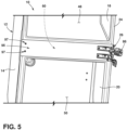
FIG. 5 is a front perspective view of the hinge bracket supporting an articulating hinge, according to some examples; -
FIG. 6 is a front plan view of the hinge bracket defining a hinge pin opening, according to some examples; -
FIG. 7 is a front perspective view of the hinge bracket defining the hinge pin opening, according to some examples; -
FIG. 8 is a rear perspective view of the refrigerator having a first hinge support positioned within an encapsulation cavity defined by an encapsulation member, according to some examples; -
FIG. 9 is an enhanced view of area IX ofFIG. 8 illustrating the first hinge support positioned within the encapsulation cavity; -
FIG. 10 is a cross-sectional view of the refrigerator cabinet structure ofFIG. 4 taken along the line X-X; -
FIG. 11 is a cross-sectional view of the refrigerator cabinet structure ofFIG. 6 taken along the line XI-XI; -
FIG. 12 is a top perspective view of the refrigerator having a top plate supporting a pair of top braces and a pair of top hinge brackets coupled with the braces, according to some examples; -
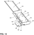
FIG. 13 is a top perspective view of the top plate supporting the pair of top braces and the pair of top hinge brackets ofFIG. 12 ; -
FIG. 14 is a bottom perspective view of the refrigerator having a bottom plate supporting a pair of bottom braces and a pair of bottom hinge brackets coupled with the bottom braces, according to some examples; and -
FIG. 15 is a bottom perspective view of the bottom plate supporting the pair of bottom braces and the pair of bottom hinge brackets ofFIG. 14 . - With reference to
FIGS. 1-15 , arefrigerator 10 includes acabinet structure 12 having awrapper 14 defining anopening 16. At least oneliner wrapper 14 and defines at least one temperature-controlledcompartment insulation cavity 22 is defined between thewrapper 14 and theliner trim breaker 24 is coupled to thewrapper 14 and theliner first hinge bracket 26 is positioned outwardly of thetrim breaker 24. Anencapsulation member 28 is positioned rearwardly of thetrim breaker 24 and defines anencapsulation cavity 30. Afirst hinge support 32 has afirst section 34 positioned along asecond hinge support 36 and asecond section 38 extending rearwardly of thefirst section 34. Thefirst hinge bracket 26 is operably coupled with the first and second hinge supports 32, 36. Asecond hinge bracket 40 may be positioned on an opposing side of a temperature-controlledcompartment second hinge bracket 40 may be operably coupled with an externally positionedbrace 42. Thebrace 42 may be fixed to aplate 44. Theplate 44 extends laterally across anexterior portion 46 of thewrapper 14. - Referring now to
FIG. 1 , therefrigerator 10 includes the insulatedcabinet structure 12 that may define the temperature-controlledcompartment refrigerator compartment 48 and/or afreezer compartment 50. One or morerefrigerator compartment doors refrigerator compartment 48, while one or morefreezer compartment doors 56 may be used to provide access to thefreezer compartment 50. The configuration of therefrigerator 10 illustrated inFIG. 1 is exemplary only and the present concept is contemplated for use in all refrigerator styles including, but not limited to, side-by-side refrigerators, whole refrigerator and freezers, and refrigerators with upper freezer compartments. Additionally, the one or morerefrigerator compartment doors freezer compartment doors 56 may be hingedly attached to thecabinet structure 12 and/or slidably attached to thecabinet structure 12 without departing from the teachings provided herein. It will also be appreciated that the assemblies provided herein may be used in any other appliance and/orcabinet structure 12 without departing from the scope of the present disclosure. - With reference to
FIG. 2 , the insulatedcabinet structure 12 also includes thetrim breaker 24 that includes anupper portion 58, acentral portion 60, and alower portion 62. In examples in which therefrigerator compartment 48 includes therefrigerator liner 18, therefrigerator liner 18 has atop wall 64,bottom wall 66, opposedsidewalls rear wall 72 which cooperate to define therefrigerator compartment 48. Therefrigerator liner 18 further includes afront edge portion 74 positioned on a front portion of therefrigerator compartment 48. - Similarly, in examples that include a
freezer compartment 50, thefreezer liner 20 includes atop wall 76, abottom wall 78, opposedsidewalls rear wall 84, which all cooperate to define thefreezer compartment 50. Therear wall 84 may be a contoured rear wall that provides a spacing S for housing cooling components for cooling therefrigerator compartment 48 and/or thefreezer compartment 50. Such components may include a compressor, a condenser, an expansion valve, an evaporator, a plurality of conduits, and other related components used for cooling the refrigerator and/orfreezer compartments freezer liner 20 further includes afront edge portion 90 positioned at a front portion of thefreezer compartment 50, which is positioned along thetop wall 76, thebottom wall 78 and theopposed sidewalls front edge portion 74 of therefrigerator liner 18 and thefront edge portion 90 of thefreezer liner 20 are configured to couple with thetrim breaker 24. - As further shown in
FIG. 2 , the insulatedcabinet structure 12 further includes thewrapper 14 which includes atop wall 92, abottom wall 94, opposedsidewalls rear wall 100 which cooperate to define theopening 16. Thewrapper 14 further includes afront edge portion 102 that defines a front portion of theopening 16. In assembly, thefront edge portion 102 of thewrapper 14 is coupled to thetrim breaker 24 around theliners refrigerator liner 18 andfreezer liner 20 are received within theopening 16 of thewrapper 14 when assembled, such that there is a spacing between the outer surfaces of therefrigerator liner 18 and thefreezer liner 20 relative to the inner surfaces of thewrapper 14. In this way, the spacing can be used to create the insulation cavity 22 (FIG. 8 ) that includes any desired type of insulation therein. For example, theinsulation cavity 22 may be a vacuum insulated space and/or contain a vacuum insulated structure therein. - The
trim breaker 24 may include linear portions that are interconnected to form a ring-like structure having an outer coupling portion and an inner coupling portion (FIG. 9 ). It will be understood that thetrim breaker 24 may have various shapes and configurations as may be required for a particular application, and it is further contemplated that thetrim breaker 24 can be used in arefrigerator 10 having multiple liners (as shown inFIG. 2 with arefrigerator liner 18 and a freezer liner 20) or in arefrigerator 10 having asingle liner - The
wrapper 14 may be made from sheet metal, polymer materials, or other suitable materials. If thewrapper 14 is made from sheet metal, thewrapper 14 may be formed utilizing known steel-forming tools and processes. Additionally and/or alternatively, thewrapper 14 may be formed from a polymer and/or elastomer material. For example, thewrapper 14 may be fabricated by thermoforming a sheet of thermoplastic polymer material. Thewrapper 14 may be constructed of a material that may be substantially impervious, such that oxygen, nitrogen, carbon dioxide, water vapor, and/or other atmospheric gases are sealed out of the insulation cavity 22 (FIG. 8 ) that is formed between thewrapper 14 andliners wrapper 14 is formed from a polymer material, the polymer material may include a plurality of layers, wherein the layers of material are selected to provide impermeability to various gases. - The
refrigerator liner 18 and thefreezer liner 20 may be made from a sheet metal material utilizing known steel-forming tools and processes. Additionally and/or alternatively, theliners liners refrigerator compartment 48 orfreezer compartment 50. Examples of layered polymer materials that may be utilized to construct thewrapper 14 orliners United States Patent Application No. 14/980,702 , entitled "MULTILAYER BARRIER MATERIALS WITH PVD OR PLASMA COATING FOR VACUUM INSULATED STRUCTURE," andUnited States Patent Application No. 14/980,778 , entitled "MULTI-LAYER GAS BARRIER MATERIALS FOR VACUUM INSULATED STRUCTURE". In some instances, thewrapper 14 and/or theliners - When the
insulated cabinet structure 12 is assembled, thetrim breaker 24 connects to thefront edge portion 102 of thewrapper 14, to thefront edge portion 74 of therefrigerator liner 18 and to thefront edge portion 90 of thefreezer liner 20 to thereby interconnect thewrapper 14 and theliners trim breaker 24 may be formed from a suitable material that is substantially impervious to gases to maintain a vacuum in theinsulation cavity 22. Thetrim breaker 24 may also have a low coefficient of thermal conductivity to reduce or prevent the transfer of heat between thewrapper 14 and theliners trim breaker 24 may be formed utilizing a molding process, such as a reaction injection molding (RIM) process. In a RIM process, thetrim breaker 24 is formed in a mold using a polyurethane material. Other materials suitable for a RIM process may include but are not limited to, polyureas, polyisocyanurates, polyesters, polyphenols, polyepoxides, thermoplastic elastomers, polycarbonate, and nylon materials. In some examples, thetrim breaker 24 is overmolded to therefrigerator liner 18, thefreezer liner 20 and thewrapper 14. In this way, theinsulated cabinet structure 12 can be a unitary part after thetrim breaker 24 is cast onto theliners wrapper 14. - When the refrigerator 10 (
FIG. 1 ) is in use, thewrapper 14 is exposed to ambient room temperature air, whereas theliners refrigerator compartment 48 or thefreezer compartment 50. With thetrim breaker 24 being made of a material that is minimally conductive, and/or substantially non-conductive, with respect to heat, thetrim breaker 24 reduces the transfer of heat from thewrapper 14 to theliners compartment - Referring now to
FIGS. 3-7 , the center portion of thetrim breaker 24, or a mullion, may be positioned between therefrigerator compartment 48 and thefreezer compartment 50. Acover assembly 95 may be positioned outwardly of the mullion to partially and/or fully conceal portions of the mullion. Thecover assembly 95 may be coupled to thetrim breaker 24, or the mullion, through one ormore fasteners 97. However, thecover assembly 95 may be coupled to thetrim breaker 24, or the mullion, through any other assembly without departing from the teachings provided herein. In some examples, thecover assembly 95 andtrim breaker 24 may be integrally formed with one another 24, 95. - The
first hinge bracket 26 may support afirst hinge 86 that may be operably coupled with thecover assembly 95 and/or trimbreaker 24 and may be generally provided laterally outward of a centerline of therefrigerator 10. Thefirst hinge bracket 26 may also be proximate the central portion of thetrim breaker 24, positioned in a vertically intermediate position along thetrim breaker 24, and/or between therefrigerator compartment 48 and thefreezer compartment 50. Asecond hinge 88 may be positioned on an opposing side of the temperature-controlledcompartment first hinge 86 and thefirst hinge bracket 26. The second hinge 88 (FIG. 12 ) may be positioned proximate a top portion of thecabinet structure 12 and/or a bottom portion of thecabinet structure 12 to support adoor FIG. 1 ) that is pivotably coupled to thecabinet structure 12. Accordingly, an upper and/or alower door first hinge 86 may be positioned on the central portion of thecabinet structure 12 with onefirst hinge 86 supporting anupper door first hinge 86 supporting thelower door 56. Alternatively, theupper door lower door 56 may be supported by the first and second hinges 86, 88 to allow for theupper door lower door 56 to rotate between an open and a closed position while the other of theupper door lower door 56 is supported by a track assembly that allows therespective door - In some examples, the
first hinge 86 may be positioned in a position that conceals one ormore fasteners 97 that retain thecover assembly 95. In some examples, the remainingfasteners 97 that are not aligned with thefirst hinge 86 may have concealers thereon to assist in obscuring the one or morecover assembly fasteners 97. - Referring to
FIGS. 4 and5 , thefirst hinge 86 is illustrated in a contracted position (FIG. 4 ) and an expanded position (FIG. 5 ). When therefrigerator 10 is assembled, the contracted position places thedoor door first hinge 86 and/or the second hinge 88 (FIG. 12 ) may also be placed in a plurality of intermediate positions between the contracted and expanded positions. In some examples, thefirst hinge 86 and/or thesecond hinge 88 may be configured as a six-link mechanism. For example, according to some examples, thefirst hinge 86 and/or thesecond hinge 88 may include a Watt's six-link mechanism for movement. The selection of a Watt's six-link mechanism allows for a wide-open position and/or a large range of motion, although other link isomers and link variations may be selected without departing from the scope of the present disclosure. Accordingly, as thedoor FIG. 4 , to an open position, as illustrated inFIG. 5 , the first and/orsecond hinge door cabinet structure 12. - Referring to
FIGS. 6-9 , the first and second hinges 86, 88 may additionally and/or alternatively include respective hinge pins 104 that may be coupled to eachhinge bracket corresponding mounting block 106 may be coupled with thedoor hinge pin 104 may have afirst end portion 108 that is inserted into acavity 110 defined by the first and/orsecond hinge brackets second end portion 112 of thehinge pin 104 may be inserted into the mountingblock 106. The mountingblock 106 may be positioned externally from an insulating cavity of thedoor door - Referring to
FIGS. 8 and9 , theinsulation cavity 22 may be defined between theliners wrapper 14. Theinsulation cavity 22 is configured to receive an insulating material that may be configured as a vacuum core material. The vacuum core material may include a plurality of individual core panels that are preformed and positioned between thewrapper 14 and theliners insulation cavity 22 after thewrapper 14, theliners trim breaker 24 are formed into a unitary composite structure. In vacuum insulated structures, a vacuum within theinsulation cavity 22 decreases heat transmission through theinsulation cavity 22. By creating a vacuum between the spaces intended to be thermally isolated, heat conduction is minimized because there is no, or less, material (e.g., air) to transfer the thermal energy between the thermally isolated spaces. In some instances, theinsulation cavity 22 may have an air pressure of less than about 1 atm, about 0.5 atm, about 0.4 atm, about 0.3 atm, about 0.2 atm, about 0.1 atm, or less than about 0.01 atm. - Referring to
FIGS. 8 and9 , afirst hinge support 32 may be positioned between a portion of thetrim breaker 24 and therefrigerator compartment 48 and/or thefreezer compartment 50. The first section 34 (FIG. 10 ) of thefirst hinge support 32 may be positioned along thesecond hinge support 36 and asecond section 38 extends rearwardly of thefirst section 34. In some instances, thesecond section 38 of thefirst hinge support 32 may couple to or otherwise contact thewrapper 14 and/or theliners cabinet structure 12. Thefirst hinge support 32 is configured to support the hinge bracket, and consequently, thedoor - With reference to
FIGS. 8-11 , theencapsulation member 28 is disposed around a portion of thefirst hinge support 32. In various examples, theencapsulation member 28 may have any desired shape. For example, as illustrated, theencapsulation member 28 has afirst portion 114 that is separated from thefirst hinge support 32 by a first distance d1 to accommodate a portion of afirst fastener 120 therein. Asecond portion 116 of theencapsulation member 28 may extend rearwardly along the side portion of thewrapper 14 in a direction that is parallel to thesecond section 38 of thefirst hinge support 32. Thesecond portion 116 may be disposed a second distance d2 from thewrapper 14. Athird portion 118 of theencapsulation member 28 may couple with thewrapper 14 at a position that is rearward of thefirst hinge support 32. As provided herein, theencapsulation member 28 may define theencapsulation cavity 30 that is impervious to theinsulation cavity 22 such that oxygen, nitrogen, carbon dioxide, water vapor, and/or other atmospheric gases are sealed out of theinsulation cavity 22. Thus, thefirst fastener 120 may be positioned within theencapsulation cavity 30 and the insulation structure, which is possibly a vacuum insulated structure, may maintain its integrity after insertion of thefirst fastener 120. - The
encapsulation member 28 may be made from a sheet metal material utilizing known steel-forming tools and processes. Additionally and/or alternatively, theencapsulation member 28 may otherwise be formed from a polymer and/or elastomer material in the form of a polymer sheet that is thermoformed. The polymer material may include one or more layers of material that are selected to provide impermeability to gases. Theencapsulation member 28 may optionally include a plurality of reinforcing structures, such as vertically spaced ridges or other forms. Additionally, and/or alternatively, theencapsulation member 28 may be integrally formed within thetrim breaker 24 and/or thewrapper 14. - As illustrated in
FIGS. 10 and 11 , theencapsulation member 28 may be coupled to thetrim breaker 24. Accordingly, thetrim breaker 24, theencapsulation member 28, and thewrapper 14 may define theencapsulation cavity 30. Thetrim breaker 24 may further define one or moretrim breaker cavities trim breaker cavity 122 may be positioned laterally inward from theencapsulation member 28 and a secondtrim breaker cavity 124 may be positioned laterally inward of the firsttrim breaker cavity 122. Thecavities trim breaker 24 may be impervious to theinsulation cavity 22 such that oxygen, nitrogen, carbon dioxide, water vapor, and/or other atmospheric gases are sealed out of theinsulation cavity 22. Thus, whenfasteners trim breaker cavities insulation cavity 22, which is possibly a vacuum insulated structure, may maintain its integrity. - The
trim breaker 24 may also define anopening 126 and thesecond hinge support 36 may be disposed within theopening 126. However, in other examples, thesecond hinge support 36 may be positioned forwardly and/or rearwardly of thetrim breaker 24 without departing from the teachings of the present disclosure. Thesecond hinge support 36 may extend at least partially in front of theencapsulation cavity 30, the firsttrim breaker cavity 122, and/or the secondtrim breaker cavity 124. - Referring still to
FIGS. 10 and 11 , thefirst hinge bracket 26 may have thefirst fastener 120 inserted therethrough that is further inserted through thecover assembly 95, thesecond hinge support 36, and/or thefirst hinge support 32. Accordingly, in some instances, thefirst hinge support 32 may be coupled to aninner surface 128 of thesecond hinge support 36. Additionally, thehinge bracket 26 is positioned proximately to anouter side 130 of thesecond hinge support 36. Asecond fastener 132 may be inserted through the hinge bracket, thecover assembly 95, and thesecond hinge support 36 and into the firsttrim breaker cavity 122. Likewise, athird fastener 134 may be positioned laterally inward of thesecond fastener 132 and inserted through thefirst hinge bracket 26, thecover assembly 95, and thesecond hinge support 36 and into the secondtrim breaker cavity 124. Accordingly, thefirst hinge support 32 may also support thesecond hinge support 36. Through the use ofmultiple fasteners cabinet structure 12 of therefrigerator 10 while thedoor trim breaker 24, and thecabinet structure 12. - Referring to
FIGS. 12-15 , thesecond hinge brackets 40 may each be mounted torespective braces 42 and positioned on an opposing side of the temperature-controlledcompartment first hinge bracket 26. Eachbrace 42 may be further mounted to aplate 44 that extends along a top and/or the bottom portion of thewrapper 14. In some examples, thebraces 42 and/or theplates 44 may each be formed from a metallic material, a polymeric material, a combination thereof, and/or any other practicable material. In examples in which thebraces 42 and/ or theplates 44 are formed from a metallic material, a stamping process may be used to form the respective component(s). In examples in which thebraces 42 and/ or theplates 44 are formed from a polymeric material, an injection molding process and/or a thermoforming process may be used to form the respective component(s). - As illustrated in
FIGS. 12 and13 , thebraces 42 may be coupled with theplate 44 that is positioned along a top portion of thewrapper 14. Thebraces 42 may also be positioned at least partially rearward of thetrim breaker 24. A locatingmember 136 may be positioned upwardly of thebrace 42 and/or hinge bracket. The locatingmember 136 may be configured to attach thecabinet structure 12 to proximate cabinetry in instances in which therefrigerator 10 is configured as a built-in type ofrefrigerator 10. - The
brace 42 that is mounted on the top portion of thecabinet structure 12 may have abase surface 138 having a stepped profile. Arearward step 140 may be positioned vertically lower than afront step 142. Thebrace 42 may also include a pair of side surfaces 144 and afront surface 146 that extends upwardly from thebase surface 138. Thefront surface 146 defines one or more voids through which afastener 148 may be positioned for coupling the hinge bracket thereto. - With further reference to
FIGS. 12 and13 , the bracket may include one ormore reinforcement ribs 150. Thereinforcement ribs 150 may be configured to provide additional support to the hinge bracket. Thereinforcement ribs 150 may be integrally formed with the hinge bracket and/or later attached thereto. - Referring to
FIGS. 14 and15 , abrace 42 may additionally and/or alternatively be coupled with theplate 44 extending laterally across a bottom portion of thewrapper 14. In some examples, a pair ofbraces 42 may be positioned on opposing side portions of theplate 44. However, theplates 44 along the top and bottom portions of thewrapper 14 may each contain any number ofbraces 42 without departing from the scope of the present disclosure. - The
brace 42 along the bottom portion of thewrapper 14 may include abase surface 152 that includes a stepped profile. Arearward step 154 may be positioned vertically above aforward step 156. Thebottom brace 42 may also include a pair of side surfaces 158 and afront surface 160. Thesecond hinge bracket 40 may be coupled to thefront surface 160 and extend forwardly of thewrapper 14 and/or thetrim breaker 24. Thesecond hinge bracket 40 may support ahinge 88 having a pin 104 (FIG. 9 ) and/or an articulating hinge without departing from the scope of the present disclosure. Theplates 44 extending along the top and bottom portions of thewrapper 14 may be positioned externally from theinsulation cavity 22 such that theinsulation cavity 22 is unaffected by the coupling of thesecond hinge brackets 40 to thecabinet structure 12. - Referring still to
FIGS. 14 and15 , one ormore shims 162 may be positioned on a bottom portion of thebraces 42 disposed along a bottom portion of thewrapper 14. Theshim 162 may be moved in a forward/rearward direction, as indicated byarrow 164, to adjust a front height of thecabinet structure 12. Theshim 162 may have a chamfered profile to allow for the vertical adjustment of thecabinet structure 12. - A variety of advantages may be derived from the use of the present disclosure. For example, use of the first and/or second hinge supports provides assistance in transferring downward forces, rotational forces, and/or torsion forces provided by the door on the cabinet structure. Moreover, the encapsulation member may assist in maintaining a desired insulative efficiency within an insulation cavity after one or more fasteners are inserted thereinto. The encapsulation member may be manufactured at low costs when compared to various solutions for maintaining a vacuum within the insulation cavity. The trim breaker may also define one or more cavities that also assist in maintaining a desired insulative efficiency within an insulation cavity after one or more fasteners are inserted thereinto. The additional fasteners may also help in supporting the first hinge bracket on the cabinet structure. The refrigerator may also include an externally positioned second hinge, which may be a top and/or bottom hinge bracket, that is supported by a brace positioned proximate a top and/or bottom portion of the wrapper. The braces positioned along a top and/or bottom portion of the wrapper may be fixed to a plate that extends laterally across the wrapper of the refrigerator. The braces positioned along a top and/or bottom portion of the wrapper and the plate support the second brackets such that the second hinge brackets also may not compromise a desired insulative efficiency within an insulation cavity of the cabinet structure.
Claims (5)
- A cabinet structure (12), comprising:a wrapper (14) spaced apart from a liner (18, 20);a trim breaker (24) coupled to the wrapper (14) and the liner (18, 20), wherein an insulation cavity (22) is defined between the wrapper (14), the liner (18,20), and the trim breaker (24); anda first hinge bracket (26) having at least one fastener (120,132,134) inserted therethrough, the fastener (120, 132, 134) being positioned externally from the insulation cavity (22),characterised by further comprising a first hinge support (32) positioned laterally outward of a second hinge support (36), the first and second hinge supports (32, 36) being each coupled with the first hinge bracket (26) proximate the trim breaker (24).
- The cabinet structure (12) of claim 1, wherein the first and second hinge supports (32, 36) include a common fastener (120) extending therethrough.
- The cabinet structure (12) of claim 1, wherein the hinge bracket (26) is operably coupled with a brace (42), the brace (42) extending forwardly of a portion of the wrapper (14).
- The cabinet structure (12) of claim 3, wherein the brace (42) is operably coupled with a plate (44), the plate (44) extending laterally along a top or bottom portion of the wrapper (14).
- The cabinet structure (12) of claim 3 or claim 4, wherein the brace (42) defines a base surface (152), two opposing side surfaces (158) and a front surface (160), the two opposing side surfaces (158) and front surface (160) extending perpendicularly from the base surface (152).
Priority Applications (1)
| Application Number | Priority Date | Filing Date | Title |
|---|---|---|---|
| EP24164860.9A EP4365523A2 (en) | 2018-05-23 | 2018-05-23 | Appliance hinge assembly |
Applications Claiming Priority (1)
| Application Number | Priority Date | Filing Date | Title |
|---|---|---|---|
| PCT/US2018/034085 WO2019226158A1 (en) | 2018-05-23 | 2018-05-23 | Appliance hinge assembly |
Related Child Applications (2)
| Application Number | Title | Priority Date | Filing Date |
|---|---|---|---|
| EP24164860.9A Division EP4365523A2 (en) | 2018-05-23 | 2018-05-23 | Appliance hinge assembly |
| EP24164860.9A Division-Into EP4365523A2 (en) | 2018-05-23 | 2018-05-23 | Appliance hinge assembly |
Publications (3)
| Publication Number | Publication Date |
|---|---|
| EP3796812A1 EP3796812A1 (en) | 2021-03-31 |
| EP3796812A4 EP3796812A4 (en) | 2022-01-26 |
| EP3796812B1 true EP3796812B1 (en) | 2024-05-01 |
Family
ID=68616930
Family Applications (2)
| Application Number | Title | Priority Date | Filing Date |
|---|---|---|---|
| EP24164860.9A Pending EP4365523A2 (en) | 2018-05-23 | 2018-05-23 | Appliance hinge assembly |
| EP18920164.3A Active EP3796812B1 (en) | 2018-05-23 | 2018-05-23 | Appliance hinge assembly |
Family Applications Before (1)
| Application Number | Title | Priority Date | Filing Date |
|---|---|---|---|
| EP24164860.9A Pending EP4365523A2 (en) | 2018-05-23 | 2018-05-23 | Appliance hinge assembly |
Country Status (4)
| Country | Link |
|---|---|
| US (1) | US11662136B2 (en) |
| EP (2) | EP4365523A2 (en) |
| CN (1) | CN112188852B (en) |
| WO (1) | WO2019226158A1 (en) |
Families Citing this family (5)
| Publication number | Priority date | Publication date | Assignee | Title |
|---|---|---|---|---|
| JP2020091066A (en) * | 2018-12-06 | 2020-06-11 | 三星電子株式会社Samsung Electronics Co.,Ltd. | Storage device and refrigerator |
| KR20210143056A (en) | 2020-05-19 | 2021-11-26 | 엘지전자 주식회사 | Center hinge and refrigerator having this |
| CN113685104B (en) * | 2020-05-19 | 2023-03-14 | Lg电子株式会社 | Multi-joint connecting rod hinge and refrigerator comprising same |
| US11486629B2 (en) * | 2020-06-25 | 2022-11-01 | Whirlpool Corporation | Refrigeration appliance cabinet assembly |
| US11486627B2 (en) * | 2020-12-30 | 2022-11-01 | Whirlpool Corporation | Reinforcement assembly for an insulated structure |
Family Cites Families (41)
| Publication number | Priority date | Publication date | Assignee | Title |
|---|---|---|---|---|
| USRE21364E (en) * | 1940-02-20 | Refrigerator | ||
| US1588707A (en) * | 1924-07-23 | 1926-06-15 | Csiga Alexander | Vacuum ice chest |
| US1948587A (en) * | 1929-06-29 | 1934-02-27 | Frigidaire Corp | Refrigerating apparatus |
| US2065608A (en) * | 1932-11-25 | 1936-12-29 | Termisk Isolation Ab | Heat insulating cabinet |
| US3917206A (en) | 1974-04-05 | 1975-11-04 | White Westinghouse Corp | Refrigerator shelf support assembly |
| US4170391A (en) * | 1978-09-21 | 1979-10-09 | General Electric Company | Refrigerator cabinet construction |
| US4557537A (en) * | 1984-05-21 | 1985-12-10 | General Electric Company | Electrical grounding arrangement and method |
| US4558503A (en) * | 1984-06-19 | 1985-12-17 | General Electric Company | Method of assembling a refrigerator |
| US4550576A (en) * | 1984-09-19 | 1985-11-05 | Whirlpool Corporation | Center rail assembly for refrigerator |
| US4606112A (en) * | 1985-06-28 | 1986-08-19 | General Electric Company | Method of assembling a refrigerator cabinet |
| US4632470A (en) * | 1985-06-28 | 1986-12-30 | General Electric | Refrigerator cabinet and method of assembly |
| US4706363A (en) * | 1986-09-09 | 1987-11-17 | General Electric Company | Method of reinforcing a structural assembly |
| US5052151A (en) * | 1988-05-10 | 1991-10-01 | Sharp Kabushiki Kaisha | Opening/closing device of a door member |
| CN1028888C (en) | 1988-05-10 | 1995-06-14 | 夏普公司 | Closed-open device of door |
| US5064255A (en) * | 1988-05-10 | 1991-11-12 | Sharp Kabushiki Kaisha | Opening/closing device of a door member |
| US5222792A (en) * | 1988-05-10 | 1993-06-29 | Sharp Kabushiki Kaisha | Opening/closing device of a door member |
| US5720536A (en) * | 1995-03-27 | 1998-02-24 | General Electric Company | Refrigerator with improved breaker strip assembly |
| JP3197258B2 (en) | 1999-09-01 | 2001-08-13 | マンドー クライメート コントロール コーポレイション | External structure for food storage and manufacturing method thereof |
| DE10126843A1 (en) | 2001-06-01 | 2002-12-05 | Bsh Bosch Siemens Hausgeraete | Refrigerator body has front opening bounded by edge and end strips, end strip inserted into joint element exerts force on edge strip that expands angle at which edge strip is joined to side wall |
| US7014283B2 (en) * | 2002-07-16 | 2006-03-21 | Maytag Corporation | Localized reinforcement system for refrigerator cabinet |
| KR101010793B1 (en) | 2004-02-11 | 2011-01-25 | 엘지전자 주식회사 | Refrigerator body and manufacturing method thereof |
| DE102005057150A1 (en) * | 2005-11-30 | 2007-06-06 | BSH Bosch und Siemens Hausgeräte GmbH | Refrigerator or freezer with reinforcement frame |
| DE102005057143A1 (en) * | 2005-11-30 | 2007-06-06 | BSH Bosch und Siemens Hausgeräte GmbH | Refrigeration unit with insulation strip for thermal decoupling of the side walls |
| US8040666B2 (en) | 2007-01-04 | 2011-10-18 | Whirlpool Corporation | Door with a service interface on an edge |
| US20110095669A1 (en) * | 2009-10-22 | 2011-04-28 | Moon William T | Refrigerator vacuum insulation application |
| CN102116554A (en) * | 2010-01-04 | 2011-07-06 | Lg电子株式会社 | Refrigerator |
| US8491070B2 (en) | 2010-10-04 | 2013-07-23 | General Electric Company | Refrigerator door pocket hinge assembly |
| KR101898487B1 (en) * | 2010-10-28 | 2018-10-04 | 엘지전자 주식회사 | A refrigerator comprising a vaccum space |
| US8480189B2 (en) | 2010-12-10 | 2013-07-09 | Robern, Inc. | Cabinet with offset hinge |
| KR20120106098A (en) | 2011-03-17 | 2012-09-26 | 삼성전자주식회사 | Refrigerator |
| CN202361736U (en) | 2011-10-29 | 2012-08-01 | 中山环威实业发展有限公司 | Novel vehicle-mounted refrigerator door |
| US20130257257A1 (en) * | 2012-04-02 | 2013-10-03 | Whirlpool Corporation | Method to create vacuum insulated cabinets for refrigerators |
| US9903638B2 (en) * | 2013-08-29 | 2018-02-27 | Electrolux Home Products, Inc. | Hinge assembly for a refrigerator |
| KR101752669B1 (en) * | 2013-12-10 | 2017-06-30 | 삼성전자주식회사 | Vacuum heat insulating material and refrigerator including the same |
| BE1021797B1 (en) | 2013-12-20 | 2016-01-19 | BLYWEERT ALUMINIUM, naamloze vennootschap | PLASTIC INSULATION RAIL, COMPOSED PROFILE AND WINDOW INCLUDING SUCH INSULATION RAIL AND METHOD OF MANUFACTURING A FRAMEWORK FOR A WINDOW |
| CN104898315A (en) | 2015-05-20 | 2015-09-09 | 上海九山电子科技有限公司 | Transparent liquid crystal display device with thermal insulation function |
| US9441779B1 (en) * | 2015-07-01 | 2016-09-13 | Whirlpool Corporation | Split hybrid insulation structure for an appliance |
| US10215471B2 (en) * | 2015-12-28 | 2019-02-26 | Whirlpool Corporation | Structural stanchion for a cabinet of an appliance |
| EP3491308B1 (en) | 2016-07-26 | 2021-03-10 | Whirlpool Corporation | Vacuum insulated structure trim breaker |
| WO2018067108A1 (en) | 2016-10-03 | 2018-04-12 | Whirlpool Corporation | Encapsulation system for a thermal bridge breaker-to-metal liner |
| WO2018070996A1 (en) * | 2016-10-11 | 2018-04-19 | Whirlpool Corporation | Structural cabinet for an appliance incorporating unitary metallic boxes |
-
2018
- 2018-05-23 WO PCT/US2018/034085 patent/WO2019226158A1/en unknown
- 2018-05-23 US US17/047,451 patent/US11662136B2/en active Active
- 2018-05-23 EP EP24164860.9A patent/EP4365523A2/en active Pending
- 2018-05-23 EP EP18920164.3A patent/EP3796812B1/en active Active
- 2018-05-23 CN CN201880093706.3A patent/CN112188852B/en active Active
Also Published As
| Publication number | Publication date |
|---|---|
| US20210148628A1 (en) | 2021-05-20 |
| EP3796812A4 (en) | 2022-01-26 |
| EP3796812A1 (en) | 2021-03-31 |
| CN112188852A (en) | 2021-01-05 |
| EP4365523A2 (en) | 2024-05-08 |
| WO2019226158A1 (en) | 2019-11-28 |
| US11662136B2 (en) | 2023-05-30 |
| CN112188852B (en) | 2023-01-03 |
Similar Documents
| Publication | Publication Date | Title |
|---|---|---|
| EP3796812B1 (en) | Appliance hinge assembly | |
| US11466927B2 (en) | Hermetically sealed overmolded plastic thermal bridge breaker with refrigerator cabinet liner and wrapper for vacuum insulation | |
| US6428130B1 (en) | Refrigerator mullion | |
| US8104853B2 (en) | Refrigerator and method of manufacturing door thereof | |
| US3910658A (en) | Refrigeration apparatus enclosure structure | |
| KR102273285B1 (en) | Refrigerator and vacuum insulation module thereof | |
| US5533311A (en) | Thermoformed plastic refrigerator door | |
| EP2639533B1 (en) | Refrigerator with sealing members disposed at end portions of a rotating bar. | |
| US3933398A (en) | Refrigeration apparatus enclosure structure | |
| JP5788232B2 (en) | refrigerator | |
| US20100024464A1 (en) | Refrigerator | |
| JP6005341B2 (en) | refrigerator | |
| MX2007000501A (en) | Refrigerator. | |
| EP3717847A1 (en) | Vacuum insulated structure with thermal bridge breaker with heat loop | |
| EP3532785A1 (en) | Refrigerator with surround illumination feature | |
| EP3491309A1 (en) | Method for ensuring reliable core material fill around the pass throughs in a vacuum insulated structure | |
| EP2893274B1 (en) | Refrigerator and manufacturing method thereof | |
| US20210325106A1 (en) | Refrigerator with surround illumination feature | |
| US11971210B2 (en) | Appliance encapsulation member | |
| CN102261802A (en) | Storage unit and household appliance having storage unit | |
| JP2000097552A (en) | Refrigerator | |
| KR20240030777A (en) | Refrigerator AND MANUFACTURING METHOD OF THE SAME | |
| CN114646171A (en) | Refrigerator door frame, refrigerator drawer door and refrigerator | |
| CN117128698A (en) | Door body for refrigerator and refrigerator | |
| CN112856904A (en) | Refrigerator door and refrigerator |
Legal Events
| Date | Code | Title | Description |
|---|---|---|---|
| STAA | Information on the status of an ep patent application or granted ep patent |
Free format text: STATUS: THE INTERNATIONAL PUBLICATION HAS BEEN MADE |
|
| STAA | Information on the status of an ep patent application or granted ep patent |
Free format text: STATUS: THE INTERNATIONAL PUBLICATION HAS BEEN MADE |
|
| PUAI | Public reference made under article 153(3) epc to a published international application that has entered the european phase |
Free format text: ORIGINAL CODE: 0009012 |
|
| STAA | Information on the status of an ep patent application or granted ep patent |
Free format text: STATUS: REQUEST FOR EXAMINATION WAS MADE |
|
| 17P | Request for examination filed |
Effective date: 20201103 |
|
| AK | Designated contracting states |
Kind code of ref document: A1 Designated state(s): AL AT BE BG CH CY CZ DE DK EE ES FI FR GB GR HR HU IE IS IT LI LT LU LV MC MK MT NL NO PL PT RO RS SE SI SK SM TR |
|
| AX | Request for extension of the european patent |
Extension state: BA ME |
|
| DAV | Request for validation of the european patent (deleted) | ||
| DAX | Request for extension of the european patent (deleted) | ||
| A4 | Supplementary search report drawn up and despatched |
Effective date: 20220105 |
|
| RIC1 | Information provided on ipc code assigned before grant |
Ipc: F25D 23/06 20060101ALI20211222BHEP Ipc: F25D 23/02 20060101ALI20211222BHEP Ipc: E06B 7/16 20060101ALI20211222BHEP Ipc: A47B 81/00 20060101AFI20211222BHEP |
|
| GRAP | Despatch of communication of intention to grant a patent |
Free format text: ORIGINAL CODE: EPIDOSNIGR1 |
|
| STAA | Information on the status of an ep patent application or granted ep patent |
Free format text: STATUS: GRANT OF PATENT IS INTENDED |
|
| RIC1 | Information provided on ipc code assigned before grant |
Ipc: F25D 23/06 20060101ALI20231123BHEP Ipc: F25D 23/02 20060101ALI20231123BHEP Ipc: E06B 7/16 20060101ALI20231123BHEP Ipc: A47B 81/00 20060101AFI20231123BHEP |
|
| INTG | Intention to grant announced |
Effective date: 20231206 |
|
| P01 | Opt-out of the competence of the unified patent court (upc) registered |
Effective date: 20231220 |
|
| GRAS | Grant fee paid |
Free format text: ORIGINAL CODE: EPIDOSNIGR3 |
|
| GRAA | (expected) grant |
Free format text: ORIGINAL CODE: 0009210 |
|
| STAA | Information on the status of an ep patent application or granted ep patent |
Free format text: STATUS: THE PATENT HAS BEEN GRANTED |
|
| AK | Designated contracting states |
Kind code of ref document: B1 Designated state(s): AL AT BE BG CH CY CZ DE DK EE ES FI FR GB GR HR HU IE IS IT LI LT LU LV MC MK MT NL NO PL PT RO RS SE SI SK SM TR |
|
| REG | Reference to a national code |
Ref country code: GB Ref legal event code: FG4D |