EP3794932A1 - Pivoting device for uniformly distributing a product on a conveying and cleaning element - Google Patents
Pivoting device for uniformly distributing a product on a conveying and cleaning element Download PDFInfo
- Publication number
- EP3794932A1 EP3794932A1 EP20183653.3A EP20183653A EP3794932A1 EP 3794932 A1 EP3794932 A1 EP 3794932A1 EP 20183653 A EP20183653 A EP 20183653A EP 3794932 A1 EP3794932 A1 EP 3794932A1
- Authority
- EP
- European Patent Office
- Prior art keywords
- combine harvester
- self
- component
- pivoting device
- conveying
- Prior art date
- Legal status (The legal status is an assumption and is not a legal conclusion. Google has not performed a legal analysis and makes no representation as to the accuracy of the status listed.)
- Pending
Links
Images


Classifications
-
- A—HUMAN NECESSITIES
- A01—AGRICULTURE; FORESTRY; ANIMAL HUSBANDRY; HUNTING; TRAPPING; FISHING
- A01D—HARVESTING; MOWING
- A01D41/00—Combines, i.e. harvesters or mowers combined with threshing devices
- A01D41/12—Details of combines
- A01D41/127—Control or measuring arrangements specially adapted for combines
- A01D41/1276—Control or measuring arrangements specially adapted for combines for cleaning mechanisms
-
- A—HUMAN NECESSITIES
- A01—AGRICULTURE; FORESTRY; ANIMAL HUSBANDRY; HUNTING; TRAPPING; FISHING
- A01D—HARVESTING; MOWING
- A01D75/00—Accessories for harvesters or mowers
- A01D75/28—Control mechanisms for harvesters or mowers when moving on slopes; Devices preventing lateral pull
- A01D75/282—Control mechanisms for harvesters or mowers when moving on slopes; Devices preventing lateral pull acting on the grain cleaning and separating device
-
- A—HUMAN NECESSITIES
- A01—AGRICULTURE; FORESTRY; ANIMAL HUSBANDRY; HUNTING; TRAPPING; FISHING
- A01D—HARVESTING; MOWING
- A01D61/00—Elevators or conveyors for binders or combines
- A01D61/008—Elevators or conveyors for binders or combines for longitudinal conveying, especially for combines
-
- A—HUMAN NECESSITIES
- A01—AGRICULTURE; FORESTRY; ANIMAL HUSBANDRY; HUNTING; TRAPPING; FISHING
- A01D—HARVESTING; MOWING
- A01D41/00—Combines, i.e. harvesters or mowers combined with threshing devices
- A01D41/06—Combines with headers
-
- A—HUMAN NECESSITIES
- A01—AGRICULTURE; FORESTRY; ANIMAL HUSBANDRY; HUNTING; TRAPPING; FISHING
- A01F—PROCESSING OF HARVESTED PRODUCE; HAY OR STRAW PRESSES; DEVICES FOR STORING AGRICULTURAL OR HORTICULTURAL PRODUCE
- A01F12/00—Parts or details of threshing apparatus
- A01F12/44—Grain cleaners; Grain separators
- A01F12/446—Sieving means
- A01F12/448—Sieve adjusting means
-
- A—HUMAN NECESSITIES
- A01—AGRICULTURE; FORESTRY; ANIMAL HUSBANDRY; HUNTING; TRAPPING; FISHING
- A01F—PROCESSING OF HARVESTED PRODUCE; HAY OR STRAW PRESSES; DEVICES FOR STORING AGRICULTURAL OR HORTICULTURAL PRODUCE
- A01F12/00—Parts or details of threshing apparatus
- A01F12/58—Control devices; Brakes; Bearings
Definitions
- the present invention relates to a self-propelled combine harvester with a pivoting device for evenly distributing a material on a reciprocating conveying and cleaning element, in particular an upper sieve when the combine harvester is tilted to the side, according to the preamble of claim 1.
- the problem with self-propelled combine harvesters is that the harvested crop loads the conveying and cleaning elements on one side when threshing on a slope, because the crop slips onto one side of the conveying and cleaning elements when the machine is tilted to the side. As a result, the cleaning effect is low because of the one-sided, heap-like accumulation of harvested material.
- a device for solving this problem is known in which the direction of oscillation of the upper sieve and thus also the conveying direction of the harvested crop is changed depending on the incline of a combine during threshing on the side slope in order to achieve an even distribution of the harvested crop on the upper sieve.
- holders grip the upper sieve, which protrude outward through slots in the combine harvester side wall and are rotatably fastened to support pieces.
- the support pieces are firmly connected with swivel levers.
- the pivot levers are in turn pivotably mounted on the combine harvester side wall with consoles.
- a coupling rod which is connected to a container, engages a pivot lever.
- the container is movably held in its upper area by the combine harvester side wall via a support arm and, on the other hand, is pivoted with a piston-cylinder unit engaging the combine harvester side wall, the piston-cylinder unit being supplied with pressurized oil via a control valve firmly connected to the container and actuated by the pendulum suspended in the container is applied. If the combine harvester tilts on the slope, the hopper also tilts. Since the pendulum is always vertical, the position of the container changes in relation to the pendulum, whereby the pendulum activates the control valve and the piston-cylinder unit is acted upon with pressure oil. When the piston rod extends or retracts, the container is pivoted, whereby the angular position of the pivot lever and thus the coupling rod the direction of oscillation of the upper sieve, in particular the size of the lateral movement component, is also changed.
- the invention is based on the problem that the device with the container and the piston-cylinder unit connected to it and the combine harvester side wall takes up a lot of installation space. Furthermore, the mechanical construction is costly and the mechanical activation of the control valve via the pendulum limits the dependence of the direction of oscillation of the upper sieve on the inclined position of the combine harvester. It is also disadvantageous that mounting or retrofitting the device is associated with a high expenditure of time due to the many components that have to be arranged on the combine harvester.
- the problems mentioned are solved in a combine harvester according to the preamble of claim 1 by the features of the characterizing part of claim 1.
- a self-propelled combine harvester with at least one pivoting device for evenly distributing a harvested crop on a reciprocating conveying and cleaning element, in particular an upper sieve is proposed, the pivoting device comprising elements for defining a direction of oscillation of the conveying and cleaning element, which are arranged between the conveying and cleaning element and a machine housing, the pivoting device comprising an actuator for stepless adjustment of at least one component of the elements from an initial position to an adjustment position, the position of the at least one component significantly defining the direction of oscillation.
- an electrical control unit is provided which directly or indirectly controls the actuator as a function of at least one state of the combine and / or crop and the starting position of the at least one component of the pivoting device.
- the electrical control unit is more cost-effective than mechanical control of the actuator and requires significantly less installation space. Furthermore, a number of characteristic curves can be stored in the electrical control unit which, in addition to a lateral inclination of the combine harvester, take into account other states for controlling the actuator, with the aim of achieving a more even distribution on the conveying and cleaning element. Such conditions can be, for example, the longitudinal inclination of the combine harvester, the moisture content of the harvested crop, the type of fruit from which the harvested crop is made up, or the signals from a throughput control device.
- the starting position corresponds to an actual position of the at least one component and the adjustment position corresponds to a target position of the at least a component
- the electrical control unit determining the adjustment position and directly or indirectly activating the actuator for moving the at least one component into the adjustment position.
- the at least one state of the combine harvester and / or crop can be the side inclination of the combine harvester, since the side inclination of the combine harvester can lead to a one-sided accumulation of the harvested material on the conveying and cleaning element, which results in a deteriorated cleaning effect of the conveying and cleaning element.
- the conveying and cleaning element is suspended in the machine housing such that it can pivot by means of pivot elements.
- the swivel elements enable the conveying and cleaning element to be mounted in a pendulous manner, so that it can be set in a reciprocating movement, for example by means of a crank.
- the elements of the pivoting device can comprise at least one holder, a pivoting rod, a pivoting fork and a holding device, the holder being fixedly arranged at one end on the side of the conveying and cleaning element and protruding outward through slots on the side of the machine housing, the holder being attached to its free end is rotatably connected to one end of the pivot rod, wherein the pivot rod is rotatably arranged on the at least one component, which is the pivot fork, wherein the pivot fork is arranged pivotably about a pivot axis on the machine housing by means of a holding device.
- This structure enables the direction of oscillation, in particular the size of a lateral movement component, of the conveying and cleaning element to be changed as a function of the position of the swivel fork.
- the structure also ensures that the means required to change the direction of oscillation are arranged outside the machine housing, so that little installation space is lost inside the machine housing.
- the arrangement of the components on a holding device enables the creation of a preassembled assembly, by means of which a quick and easy assembly and retrofitting of the pivoting device on the machine housing can be carried out.
- further components such as sensors and / or actuators, can be arranged on the holding device.
- the actuator can be arranged at least approximately parallel to the at least one component. This further reduces the installation space required and achieves a more compact arrangement of the components.
- the more compact Arrangement offers the advantage that more installation space is created for other components of the combine, such as the tires.
- the actuator can preferably be designed as a piston-cylinder unit in order to enable simple pivoting of the pivot fork about the pivot axis.
- a cylinder of the piston-cylinder unit which is usually composed of a cylinder and a piston rod, can be rotatably connected to the pivoting fork on the side facing the piston rod by means of a fastening element, the piston rod of the piston-cylinder unit being rotatably connected to the holding device.
- a position sensor is arranged between the machine housing and the at least one component, preferably the pivoting fork, so that it receives a measurement signal for determining the position of the at least one component relative to the machine housing, in particular an angle between the machine housing and the at least one component around the pivot axis.
- the position of the at least one component relative to the machine housing is required for direct or indirect control of the actuator.
- the combine harvester has an inclination sensor which detects the lateral inclination of the combine harvester, since the lateral inclination can be required as a state for direct or indirect control of the actuator.
- the pivoting device can have a zero position, wherein at least one first position element, preferably a stop, can be provided on the holding device, which has a surface for spanning a plane, the plane having a defined second position element, preferably a bolt, which is arranged on the at least one component, preferably the pivot fork, tangent in the zero position of the pivot device.
- the underlying purpose of the first and second position elements is a simple adjustment of the pivoting device into the zero position. This is in this advantageous embodiment only an object with a flat surface, such as a ruler, is required.
- the zero position of the pivoting device is in a position of the pivoting device in which the object lies flat against the surface of the first position element and at the same time is tangent to the second position element.
- the pivoting device is designed in such a way that, in its zero position, the influence of the pivoting device on the direction of oscillation of the conveying and cleaning element assumes a minimum.
- the zero position is provided for a harvesting process with a level subsoil, in which the reciprocating movement of the conveying and cleaning element is sufficient in an unchanged state for an even distribution of the harvested crop.
- the actuator is designed as a hydraulic piston-cylinder unit, the hydraulic piston-cylinder unit being acted upon with pressure oil via a control valve, the electrical control unit activating the control valve.
- the advantage of using a hydraulic piston-cylinder unit is that it can be connected to a hydraulic system in the combine harvester. Furthermore, hydraulic piston-cylinder units achieve high tensile and compressive forces.
- the hydraulic piston-cylinder unit can form a flow between a first and a second hydraulic line in at least one end position. Moving the hydraulic piston-cylinder unit into such an end position can serve to simplify venting, since with a corresponding arrangement when pressure oil flows through the hydraulic piston-cylinder unit, the air present is diverted from the hydraulic piston-cylinder unit.
- Such a process could, for example, be initiated automatically at defined time intervals or by manual activation.
- Such an automatic venting process leads to a reduced expenditure of time for maintenance work and facilitates the commissioning of the pivoting device.
- the actuator can be designed as an electrical adjusting device, in particular as an electric lifting cylinder. This simplifies the installation of the actuator, since an electrical adjustment device only requires power lines that can be easily laid. Furthermore, there is no need for a control valve, so that the actuator can be controlled directly by the electrical control unit.
- a harvesting machine designed as a self-propelled combine harvester 1 which has a driver's cab 2, a grain tank 3 located behind it and an internal combustion engine 4 connected to it. Furthermore, the self-propelled combine harvester 1 receives a header 5 in its front area.
- the header 5 grabs the stalks to be harvested (not shown) with a reel 6 and cuts it off close to the ground by means of a mowing device (not shown), whereupon the crop from the header 5 is fed to a threshing and separating device 8 by an inclined conveyor 7.
- This threshing and separating device 8 is designed as a multi-drum arrangement of a tangential threshing mechanism and consists of a pre-acceleration drum 9, a threshing drum 10 and a feed drum 11. Separation baskets 9a, 10a and 11a are assigned to these drums 9, 10 and 11, respectively.
- the threshed harvested crop passes through the separation baskets 9a, 10a and 11a on a preparation floor 12, over which it is oscillatingly moved sieves, which include a conveyor and cleaning element 88, which is designed as an upper sieve 22, and a lower sieve 23, a Cleaning device 13 is supplied.
- a cleaning fan 14 interacts with the sieves of the cleaning device 13, which generates an air flow in the area of the sieves, whereby chaff and short straw are separated and conveyed out of the combine harvester 1.
- the cleaned crop passing through the sieves of the cleaning device 13 arrives in a transverse screw conveyor 15, which transports the crop to a grain elevator (not shown) that is connected to the grain tank 3.
- the combine harvester 1 shown has a separating rotor 17 extending in the longitudinal direction of the combine harvester 1, but in an alternative embodiment the combine harvester 1 can also be equipped with shakers.
- the separating rotor 17 is also surrounded radially by a separator housing 18 which has separation openings (not shown in greater detail) in its lower region and which is closed in the upper region, that is to say impermeable.
- Fig. 2 shows a first sieve box 29 which holds the upper sieve 22 and a second sieve box 32 which holds the lower sieve 23.
- the first screen box 29 is suspended from the front pivoting elements 24 and rear pivoting element 25, each of which is freely pivotable at its upper end on brackets 27 coupled to the machine housing 26 and is also freely pivotable at its lower end by means of bearings 28 first screen box 29 are stored.
- a connecting rod 30 connects the first screen box 29 to an eccentric drive 31 which is known per se and is not explained in greater detail. By means of the eccentric drive 31, the upper screen 22 is excited to swing back and forth. Furthermore, in Fig.
- a pivoting device 37 according to the invention and to be described in more detail is shown, which has a holder 38 which is firmly connected to the first screen box 29.
- the excerpt A of the Fig. 2 shows the pivoting device 37 and a section of the machine housing 26 on which the pivoting device 37 is arranged by means of a holding device 54.
- FIG. 3a the pivoting device 37 according to the invention is shown in a top view with a section of the upper sieve 22 and a lateral section of the machine housing 26.
- Figure 3b shows the pivoting device 37 in a side view.
- the holder 38 of the pivoting device is fixedly connected at one end to a longitudinal side 39 of the first sieve box 29 extending essentially in the direction of travel FR, for example screwed by means of screws 40.
- bores 41 can be provided, preferably in a central area 42 of the longitudinal side 39 of the first screen box 29.
- a first slot opening 43 is provided on the machine housing 26, through which the holder 38 protrudes to the outside.
- the holder 38 is rotatably arranged at its free end by means of a first metal rubber bearing 44 at one end of a component 51, which is designed as a pivot rod 45.
- the first metal-rubber bearing 44 allows a rotary movement of the holder 38 with respect to the pivot rod 45 with essentially three rotational degrees of freedom.
- the pivot rod 45 is in turn arranged with the free end rotatably by means of a second metal rubber bearing 46 on a pivot fork 47.
- the swivel fork 47 has a first profile element 48 and a second profile element 49, which are arranged essentially in a V-shape to one another.
- the pivot rod 47 is mounted by means of the second metal rubber bearing 46.
- the first profile element 48 and the second profile element 49 are arranged on the holding device 54 so that they can rotate about a pivot axis 53 extending essentially in a vertical direction VR.
- the holding device 54 has a support side 55 with a second slot opening 56 located in the middle of this.
- the support side 55 is stationary on the machine housing 26 arranged, for example screwed, so that the first slot opening 43 and the second slot opening 56 overlap.
- a fastening element 89 which is designed as a U-shaped profile element 60, is fixed in place on the pivot fork 47 in a central region 59, which is located essentially centrally between the tapered side 50 of the V-shaped pivot fork 47 and the holding device 54 the first profile element 48 and the second profile element 49 arranged, for example welded.
- a cylinder 61 of an actuator 58 designed as a hydraulic piston-cylinder unit 62 is mounted on the U-shaped profile element 60 on the side 64 facing the piston rod 63 so as to be rotatable about an axis 65 extending parallel to the pivot axis 53.
- the hydraulic piston-cylinder unit 62 extends essentially parallel to the pivot fork 47.
- the holding device 54 has a first element 66 which extends transversely to the support side 55.
- the piston rod 63 of the hydraulic piston-cylinder unit 62 is mounted at its free end so that it can rotate about an axis of rotation 67 extending parallel to the pivot axis 53.
- a position sensor 68 which is designed as an angle potentiometer 69, is arranged on the holding device 54.
- a measuring sensor 70 is assigned to the angle potentiometer 69 so that it can rotate about the pivot axis 53 and is in contact with the pivot fork 47 by means of a bolt 71 attached to the pivot fork 47, so that it reproduces a rotational movement of the pivot fork 47 about the pivot axis 53.
- the position sensor 68 is arranged on the pivot axis 53, so that a simple evaluation of the measurement data of the position sensor 68 is possible.
- a first position element 57 which is designed as a stop 72, is fixedly arranged on the holding device 54 and has a flat surface 73 which extends parallel to the pivot axis 53. Furthermore, the flat surface 73 is designed in such a way that it spans a plane (not shown) which, in a zero position 74 of the pivoting device 37, is tangent to a second position element 52, which is designed as a bolt 71. This enables the pivoting device 37 to be easily adjusted into the zero position 74. All that is required for this is an object 75 with a flat surface, for example a ruler 76. In the zero position 74, the flat surface of the object 75 rests flat against the surface 73 and is tangent to the bolt 71 be executed.
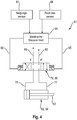
- Fig. 4 shows a circuit diagram 81 for controlling the hydraulic piston-cylinder unit 62.
- the hydraulic piston-cylinder unit 62 can be acted upon with pressure oil by means of a first hydraulic line 77 and a second hydraulic line 78.
- the first and second hydraulic lines 77, 78 are connected to a control valve 79, which is designed as a 4/3-way valve 80 in the exemplary embodiment.
- the control valve 79 is acted upon by means of a pump line 82 with pressurized oil of a hydraulic system (not shown) present in the combine harvester 1 and is connected to the tank of this system by a tank line 83.
- the control valve 79 is activated by an electrical control unit 84 via the control lines 85, 86.
- the electrical control unit 84 controls the control valve 79 in the exemplary embodiment as a function of the measurement results of the position sensor 68 and an inclination sensor 87.
- the inclination sensor 87 which is usually already present in the combine harvester 1, determines the lateral inclination of the combine harvester 1. Accordingly, the electrical control unit 84 controls the switching positions of the control valve 79 in such a way that the piston rod 63 of the hydraulic piston-cylinder unit 62 is extended, retracted or held in its position becomes.
- the invention is not limited to the measurement results of the inclination and position sensors 87, 68 for activating the control valve 79 mentioned in the exemplary embodiment, but can be based on further criteria, such as a nodding movement of the combine 1, the nature of the crop or throughput measurements of the crop in the combine 1 be expanded.
- FIG. 5a shows schematically a position of the pivoting device 47 with retracted piston rod 63 and Figure 5b with the piston rod 63 extended.
- the pivoting movement of the upper sieve 22 resulting from these two possible intermediate positions are indicated by the arrows A and B.
- the hydraulic piston-cylinder unit 62 can be designed as an electrical adjusting device, such as an electric lifting cylinder. Furthermore, as an alternative to detecting the position of the swivel fork 47 by means of the position sensor 68, a position measurement on the actuator 58 can be carried out.
Landscapes
- Life Sciences & Earth Sciences (AREA)
- Environmental Sciences (AREA)
- Harvester Elements (AREA)
- Combines (AREA)
Abstract
Die Erfindung betrifft einen Selbstfahrender Mähdrescher (1) mit zumindest einer Verschwenkvorrichtung (37) zur gleichmäßigen Verteilung eines Ernteguts auf einem hin- und herschwingenden Förder- und Reinigungsorgan (88), insbesondere einem Obersieb (22), wobei die Verschwenkvorrichtung (37) Elemente (38, 45, 47, 54) zum Definieren einer Schwingrichtung des Förder- und Reinigungsorgans (88) umfasst, welche zwischen dem Förder- und Reinigungsorgan (88) und einem Maschinengehäuse (26), angeordnet sind, wobei die Verschwenkvorrichtung (37) einen Aktor (58) zum stufenlosen Verstellen zumindest eines Bauteils (51) der Elemente (38, 45, 47, 54) von einer Ausgangsposition in eine Verstellposition umfasst, wobei die Position des zumindest einen Bauteils (51) die Schwingrichtung maßgeblich definiert, wobei eine elektrische Steuereinheit (84) vorgesehen ist, welche in Abhängigkeit zumindest eines Zustands des Mähdreschers (1) und/oder Ernteguts und der Ausgangsposition des zumindest einen Bauteils (51) der Verschwenkvorrichtung (37) den Aktor (58) direkt oder indirekt ansteuert.


Description
Die vorliegende Erfindung betrifft einen selbstfahrenden Mähdrescher mit einer Verschwenkvorrichtung zur gleichmäßigen Verteilung eines Gutes auf einem hin- und herschwingenden Förder- und Reinigungsorgan, insbesondere einem Obersieb bei Seitenneigung des Mähdreschers, gemäß dem Oberbegriff des Anspruchs 1.The present invention relates to a self-propelled combine harvester with a pivoting device for evenly distributing a material on a reciprocating conveying and cleaning element, in particular an upper sieve when the combine harvester is tilted to the side, according to the preamble of
Bei selbstfahrenden Mähdreschern besteht das Problem, dass das Erntegut beim Drusch am Hang die Förder- und Reinigungsorgane einseitig belastet, weil das Erntegut bei der Seitenneigung der Maschine auf eine Seite der Förder- und Reinigungsorgane rutscht. Hierdurch ist der Reinigungseffekt wegen der einseitigen haufenförmigen Ansammlung von Erntegut gering.The problem with self-propelled combine harvesters is that the harvested crop loads the conveying and cleaning elements on one side when threshing on a slope, because the crop slips onto one side of the conveying and cleaning elements when the machine is tilted to the side. As a result, the cleaning effect is low because of the one-sided, heap-like accumulation of harvested material.
Aus der
Der Erfindung liegt das Problem zugrunde, dass die Vorrichtung mit dem Behälter sowie dem mit diesem und der Mähdrescherseitenwand verbundenen Kolbenzylindereinheit viel Bauraum beansprucht. Weiterhin ist die mechanische Konstruktion kostenintensiv und die mechanische Aktivierung des Steuerventils über das Pendel schränkt die Abhängigkeit der Schwingrichtung des Obersiebs auf die Schräglage des Mähdreschers ein. Nachteilig ist ebenfalls, dass ein Montieren oder Nachrüsten der Vorrichtung auf Grund der vielen Komponenten die am Mähdrescher anzuordnen sind mit einem hohen zeitlichen Aufwand verbunden ist. Die genannten Probleme werden bei einem Mähdrescher nach dem Oberbegriff des Anspruchs 1 durch die Merkmale des kennzeichnenden Teils von Anspruch 1 gelöst.The invention is based on the problem that the device with the container and the piston-cylinder unit connected to it and the combine harvester side wall takes up a lot of installation space. Furthermore, the mechanical construction is costly and the mechanical activation of the control valve via the pendulum limits the dependence of the direction of oscillation of the upper sieve on the inclined position of the combine harvester. It is also disadvantageous that mounting or retrofitting the device is associated with a high expenditure of time due to the many components that have to be arranged on the combine harvester. The problems mentioned are solved in a combine harvester according to the preamble of
Gemäß dem Anspruch 1 wird ein selbstfahrender Mähdrescher mit zumindest einer Verschwenkvorrichtung zur gleichmäßigen Verteilung eines Ernteguts auf einem hin- und herschwingenden Förder- und Reinigungsorgan, insbesondere einem Obersieb, vorgeschlagen, wobei die Verschwenkvorrichtung Elemente zum Definieren einer Schwingrichtung des Förder- und Reinigungsorgans umfasst, welche zwischen dem Förder- und Reinigungsorgan und einem Maschinengehäuse, angeordnet sind, wobei die Verschwenkvorrichtung einen Aktor zum stufenlosen Verstellen zumindest eines Bauteils der Elemente von einer Ausgangsposition in eine Verstellposition umfasst, wobei die Position des zumindest einen Bauteils die Schwingrichtung maßgeblich definiert. Erfindungsgemäß ist eine elektrische Steuereinheit vorgesehen, welche in Abhängigkeit zumindest eines Zustands des Mähdreschers und/oder Ernteguts und der Ausgangsposition des zumindest einen Bauteils der Verschwenkvorrichtung den Aktor direkt oder indirekt ansteuert. Die elektrische Steuereinheit ist gegenüber einer mechanischen Ansteuerung des Aktors kostengünstiger und benötigt deutlich weniger Bauraum. Weiterhin können eine Mehrzahl an Kennlinien in der elektrischen Steuereinheit hinterlegt werden, die neben einer Seitenneigung des Mähdreschers weitere Zustände für die Ansteuerung des Aktors berücksichtigen, mit dem Ziel eine gleichmäßigere Verteilung auf dem Förder- und Reinigungsorgan zu erreichen. Solche Zustände können beispielsweise die Längsneigung des Mähdreschers, die Feuchtigkeit des Ernteguts, die Fruchtart aus der sich das Erntegut zusammensetzt oder die Signale eines Durchsatzkontrollgeräts sein.According to
In einer vorteilhaften Ausgestaltung entspricht die Ausgangsposition einer Ist-Position des zumindest einen Bauteils und die Verstellposition entspricht einer Zielposition des zumindest einen Bauteils, wobei die elektrische Steuereinheit die Verstellposition ermittelt und den Aktor zum Verfahren des zumindest einen Bauteils in die Verstellposition direkt oder indirekt ansteuert.In an advantageous embodiment, the starting position corresponds to an actual position of the at least one component and the adjustment position corresponds to a target position of the at least a component, the electrical control unit determining the adjustment position and directly or indirectly activating the actuator for moving the at least one component into the adjustment position.
Insbesondere kann der zumindest eine Zustand des Mähdreschers und/oder Ernteguts die Seitenneigung des Mähdreschers sein, da die Seitenneigung des Mähdreschers zu einer einseitigen Anhäufung des Ernteguts auf dem Förder- und Reinigungsorgan führen kann, wodurch sich ein verschlechterter Reinigungseffekt des Förder- und Reinigungsorgans ergibt.In particular, the at least one state of the combine harvester and / or crop can be the side inclination of the combine harvester, since the side inclination of the combine harvester can lead to a one-sided accumulation of the harvested material on the conveying and cleaning element, which results in a deteriorated cleaning effect of the conveying and cleaning element.
In einer vorteilhaften Ausgestaltung ist vorgesehen, dass das Förder- und Reinigungsorgan mittels Schwenkelementen verschwenkbar im Maschinengehäuse aufgehängt ist. Die Schwenkelemente ermöglichen eine pendelnde Lagerung des Förder- und Reinigungsorgans, sodass dieses beispielsweise über eine Kurbel in eine hin- und herschwingende Bewegung versetzt werden kann.In an advantageous embodiment it is provided that the conveying and cleaning element is suspended in the machine housing such that it can pivot by means of pivot elements. The swivel elements enable the conveying and cleaning element to be mounted in a pendulous manner, so that it can be set in a reciprocating movement, for example by means of a crank.
Insbesondere können die Elemente der Verschwenkvorrichtung zumindest einen Halter, eine Schwenkstange, eine Schwenkgabel sowie eine Haltevorrichtung umfassen, wobei der Halter an einem Ende seitlich am Förder- und Reinigungsorgan ortsfest angeordnet ist und durch Schlitze seitlich am Maschinengehäuse nach außen ragt, wobei der Halter an seinem freien Ende drehbar an einem Ende der Schwenkstange verbunden ist, wobei die Schwenkstange drehbar an dem zumindest einen Bauteil, welches die Schwenkgabel ist, angeordnet ist, wobei die Schwenkgabel verschwenkbar um eine Schwenkachse am Maschinengehäuse mittels einer Haltevorrichtung angeordnet ist. Dieser Aufbau ermöglicht in Abhängigkeit von der Position der Schwenkgabel eine Änderung der Schwingrichtung, insbesondere der Größe einer seitlichen Bewegungskomponente, des Förder- und Reinigungsorgans. Weiterhin wird durch den Aufbau erreicht, dass die zur Änderung der Schwingrichtung erforderlichen Mittel außerhalb des Maschinengehäuses angeordnet sind, so dass wenig Bauraum innerhalb des Maschinengehäuses verloren geht. Die Anordnung der Komponenten an einer Haltevorrichtung ermöglicht das Erstellen einer vormontierten Baugruppe, mittels der ein schnelles und einfaches Montieren sowie Nachrüsten der Verschwenkvorrichtung am Maschinengehäuse durchführbar ist. Hierfür kann ein Anordnen von weiteren Komponenten, wie beispielsweise Sensoren und/oder Aktoren an der Haltevorrichtung vorgesehen sein.In particular, the elements of the pivoting device can comprise at least one holder, a pivoting rod, a pivoting fork and a holding device, the holder being fixedly arranged at one end on the side of the conveying and cleaning element and protruding outward through slots on the side of the machine housing, the holder being attached to its free end is rotatably connected to one end of the pivot rod, wherein the pivot rod is rotatably arranged on the at least one component, which is the pivot fork, wherein the pivot fork is arranged pivotably about a pivot axis on the machine housing by means of a holding device. This structure enables the direction of oscillation, in particular the size of a lateral movement component, of the conveying and cleaning element to be changed as a function of the position of the swivel fork. The structure also ensures that the means required to change the direction of oscillation are arranged outside the machine housing, so that little installation space is lost inside the machine housing. The arrangement of the components on a holding device enables the creation of a preassembled assembly, by means of which a quick and easy assembly and retrofitting of the pivoting device on the machine housing can be carried out. For this purpose, further components, such as sensors and / or actuators, can be arranged on the holding device.
In einer vorteilhaften Ausgestaltung kann der Aktor zumindest annähernd parallel zu dem zumindest einen Bauteil angeordnet sein. Hierdurch wird der benötigte Bauraum weiter reduziert und eine kompaktere Anordnung der Komponenten erreicht. Die kompaktere Anordnung bietet den Vorteil, dass mehr Bauraum für andere Bauteile des Mähdreschers, wie beispielsweise den Reifen, geschaffen wird.In an advantageous embodiment, the actuator can be arranged at least approximately parallel to the at least one component. This further reduces the installation space required and achieves a more compact arrangement of the components. The more compact Arrangement offers the advantage that more installation space is created for other components of the combine, such as the tires.
Bevorzugt kann der Aktor als Kolbenzylindereinheit ausgebildet sein, um ein einfaches Verschwenken der Schwenkgabel um die Schwenkachse zu ermöglichen.The actuator can preferably be designed as a piston-cylinder unit in order to enable simple pivoting of the pivot fork about the pivot axis.
In einer bevorzugten Ausführungsform kann ein Zylinder der Kolbenzylindereinheit, welche sich üblicherweise aus einem Zylinder und einer Kolbenstange zusammensetzt, auf der Kolbenstange zugewandten Seite mittels eines Befestigungselements mit der Schwenkgabel drehbeweglich verbunden sein, wobei die Kolbenstange der Kolbenzylindereinheit mit der Haltevorrichtung drehbeweglich verbunden ist.
Hierdurch wird die zuvor genannte, annähernd parallele Anordnung des Aktors zu der Schwenkgabel ermöglicht. Insbesondere ergibt sich durch die drehbewegliche Verbindung des Befestigungselements mit dem Zylinder an der Kolbenstange zugewandten Seite des Zylinders ein erweiterter Verschwenkbereich der Schwenkgabel.In a preferred embodiment, a cylinder of the piston-cylinder unit, which is usually composed of a cylinder and a piston rod, can be rotatably connected to the pivoting fork on the side facing the piston rod by means of a fastening element, the piston rod of the piston-cylinder unit being rotatably connected to the holding device.
This enables the aforementioned, approximately parallel arrangement of the actuator to the swivel fork. In particular, the rotatable connection of the fastening element to the cylinder on the side of the cylinder facing the piston rod results in an expanded pivoting range of the pivoting fork.
Eine vorteilhafte Weiterbildung sieht vor, dass ein Positionssensor derart zwischen dem Maschinengehäuse und dem zumindest einen Bauteil, vorzugsweise der Schwenkgabel, angeordnet ist, sodass dieser ein Messsignal zur Bestimmung der Position des zumindest einen Bauteils relativ zu dem Maschinengehäuse, insbesondere einen Winkel zwischen dem Maschinengehäuse und dem zumindest einen Bauteil um die Schwenkachse, erfasst. Die Position des zumindest einen Bauteils relativ zum Maschinengehäuse ist zur direkten oder indirekten Ansteuerung des Aktors erforderlich.An advantageous development provides that a position sensor is arranged between the machine housing and the at least one component, preferably the pivoting fork, so that it receives a measurement signal for determining the position of the at least one component relative to the machine housing, in particular an angle between the machine housing and the at least one component around the pivot axis. The position of the at least one component relative to the machine housing is required for direct or indirect control of the actuator.
Weiterhin ist vorgesehen, dass der Mähdrescher einen Neigungssensor aufweist, der die Seitenneigung des Mähdreschers erfasst, da die Seitenneigung als Zustand zur direkten oder indirekten Ansteuerung des Aktors erforderlich sein kann.It is also provided that the combine harvester has an inclination sensor which detects the lateral inclination of the combine harvester, since the lateral inclination can be required as a state for direct or indirect control of the actuator.
In einer vorteilhaften Ausgestaltung kann die Verschwenkvorrichtung eine Nullstellung aufweisen, wobei zumindest ein erstes Positionselement, vorzugsweise ein Anschlag, an der Haltevorrichtung vorgesehen sein kann, welches eine Oberfläche zum aufspannen einer Ebene aufweist, wobei die Ebene ein definiertes zweites Positionselement, vorzugsweise einen Bolzen, welches auf dem zumindest einen Bauteil, vorzugsweise der Schwenkgabel, angeordnet ist, in der Nullstellung der Verschwenkvorrichtung tangiert. Der zugrundeliegende Zweck des ersten und zweiten Positionselements ist eine einfache Justierung der Verschwenkvorrichtung in die Nullstellung. Hierfür ist bei dieser vorteilhaften Ausgestaltung lediglich ein Objekt mit einer ebenen Oberfläche, beispielsweise ein Lineal, erforderlich. In einer Stellung der Verschwenkvorrichtung, in der das Objekt eben an der Oberfläche des ersten Positionselements anliegt und gleichzeitig das zweite Positionselement tangiert, befindet sich die Nullstellung der Verschwenkvorrichtung. Eine Anordnung, in der sich das erste Positionselement auf dem zumindest einen Bauteil und das zweite Positionselement auf der Haltevorrichtung, oder einem Bauelement, welches gegenüber dem zumindest einen Bauteil ortsfest an der Rahmenstruktur des Mähdreschers befestigt ist, bildet eine mögliche Alternative.In an advantageous embodiment, the pivoting device can have a zero position, wherein at least one first position element, preferably a stop, can be provided on the holding device, which has a surface for spanning a plane, the plane having a defined second position element, preferably a bolt, which is arranged on the at least one component, preferably the pivot fork, tangent in the zero position of the pivot device. The underlying purpose of the first and second position elements is a simple adjustment of the pivoting device into the zero position. This is in this advantageous embodiment only an object with a flat surface, such as a ruler, is required. The zero position of the pivoting device is in a position of the pivoting device in which the object lies flat against the surface of the first position element and at the same time is tangent to the second position element. An arrangement in which the first position element is on the at least one component and the second position element on the holding device, or a component which is fixedly attached to the frame structure of the combine with respect to the at least one component, forms a possible alternative.
Vorteilhaft ist es, wenn die Verschwenkvorrichtung derart ausgestaltet ist, dass in ihrer Nullstellung der Einfluss der Verschwenkvorrichtung auf die Schwingrichtung des Förder- und Reinigungsorgans ein Minimum annimmt. Die Nullstellung ist für einen Erntevorgang bei ebenen Unterboden vorgesehen, bei der die hin- und herschwingende Bewegung des Förder- und Reinigungsorgans in einem unveränderten Zustand für eine gleichmäßige Verteilung des Ernteguts ausreicht.It is advantageous if the pivoting device is designed in such a way that, in its zero position, the influence of the pivoting device on the direction of oscillation of the conveying and cleaning element assumes a minimum. The zero position is provided for a harvesting process with a level subsoil, in which the reciprocating movement of the conveying and cleaning element is sufficient in an unchanged state for an even distribution of the harvested crop.
In einer weiteren Ausgestaltung der Erfindung wird vorgeschlagen, dass der Aktor als hydraulische Kolbenzylindereinheit ausgeführt ist, wobei die hydraulische Kolbenzylindereinheit über ein Steuerventil mit Drucköl beaufschlagt wird, wobei die elektrische Steuereinheit das Steuerventil ansteuert. Vorteilhaft an der Verwendung einer hydraulischen Kolbenzylindereinheit ist, dass diese an ein im Mähdrescher vorhandenes Hydrauliksystems angeschlossen werden können. Weiterhin erreichen hydraulische Kolbenzylindereinheiten hohe Zug- und Druckkräfte.In a further embodiment of the invention it is proposed that the actuator is designed as a hydraulic piston-cylinder unit, the hydraulic piston-cylinder unit being acted upon with pressure oil via a control valve, the electrical control unit activating the control valve. The advantage of using a hydraulic piston-cylinder unit is that it can be connected to a hydraulic system in the combine harvester. Furthermore, hydraulic piston-cylinder units achieve high tensile and compressive forces.
In einer weiteren Ausgestaltung der Erfindung wird vorgeschlagen, dass die hydraulische Kolbenzylindereinheit in zumindest einer Endlage einen Durchfluss zwischen einer ersten und einer zweiten Hydraulikleitung bilden kann. Ein Verfahren der hydraulischen Kolbenzylindereinheit in eine derartige Endlage, kann zum vereinfachten Entlüften dienen, da bei einer entsprechenden Anordnung beim durchfließen der hydraulischen Kolbenzylindereinheit mit Drucköl die vorhandene Luft aus der hydraulischen Kolbenzylindereinheit abgeleitet wird. Ein solcher Vorgang könnte beispielsweise automatisch in definierten Zeitabständen oder durch eine manuelle Aktivierung eingeleitet werden. Ein solcher automatischer Entlüftungsvorgang führt zu einem reduzierten Zeitaufwand für Wartungsarbeiten und erleichtert die Inbetriebnahme der Verschwenkvorrichtung.In a further embodiment of the invention it is proposed that the hydraulic piston-cylinder unit can form a flow between a first and a second hydraulic line in at least one end position. Moving the hydraulic piston-cylinder unit into such an end position can serve to simplify venting, since with a corresponding arrangement when pressure oil flows through the hydraulic piston-cylinder unit, the air present is diverted from the hydraulic piston-cylinder unit. Such a process could, for example, be initiated automatically at defined time intervals or by manual activation. Such an automatic venting process leads to a reduced expenditure of time for maintenance work and facilitates the commissioning of the pivoting device.
In einer weiteren Ausgestaltung der Erfindung wird vorgeschlagen, dass der Aktor als elektrische Verstelleinrichtung, insbesondere als Elektrohubzylinder, ausgeführt sein kann. Dies vereinfacht die Installation des Aktors, da eine elektrische Verstelleinrichtung lediglich leicht verlegbare Stromleitungen benötigt. Weiterhin entfällt die Notwendigkeit eines Steuerventils, sodass der Aktor direkt von der elektrischen Steuereinheit angesteuert werden kann.In a further embodiment of the invention, it is proposed that the actuator can be designed as an electrical adjusting device, in particular as an electric lifting cylinder. This simplifies the installation of the actuator, since an electrical adjustment device only requires power lines that can be easily laid. Furthermore, there is no need for a control valve, so that the actuator can be controlled directly by the electrical control unit.
Weitere vorteilhafte Ausgestaltungen sind Gegenstand weiterer Unteransprüche und werden nachfolgend an Hand eines in mehreren Figuren dargestellten Ausführungsbeispiels beschrieben. Es zeigen:
- Fig. 1
- eine schematische Seitenansicht einer als Mähdrescher ausgeführten selbstfahrenden Erntemaschine;
- Fig. 2
- eine Seitenansicht der Verschwenkvorrichtung, welche an einem ersten Siebkasten, welcher das Obersieb eines Mähdreschers haltert, angeordnet ist sowie eine Seitenansicht eines zweiten Siebkastens, welcher das Untersieb eines Mähdreschers haltert und einen Ausszug A, welcher die mit einer Haltevorrichtung am Maschinengehäuse des Mähdreschers angeordnete Verschwenkvorrichtung zeigt,
- Fig. 3a
- eine Draufsicht einer Verschwenkvorrichtung zum Verändern der Schwingrichtung;
- Fig. 3b
- eine Seitenansicht der Verschwenkvorrichtung;
- Fig. 4
- einen Schaltplan zum Ansteuern der Kolbenzylindereinheit;
- Fig. 5a
- eine schematische Ansicht der Verschwenkvorrichtung mit eingefahrener Kolbenzylindereinheit;
- Fig. 5b
- eine schematische Ansicht der Verschwenkvorrichtung mit ausgefahrener Kolbenzylindereinheit.
- Fig. 1
- a schematic side view of a self-propelled harvesting machine designed as a combine;
- Fig. 2
- a side view of the pivoting device, which is arranged on a first sieve box, which holds the upper sieve of a combine harvester, and a side view of a second sieve box, which holds the lower sieve of a combine harvester, and an extract A, which shows the pivoting device arranged with a holding device on the machine housing of the combine harvester ,
- Fig. 3a
- a plan view of a pivoting device for changing the direction of oscillation;
- Figure 3b
- a side view of the pivoting device;
- Fig. 4
- a circuit diagram for controlling the piston-cylinder unit;
- Figure 5a
- a schematic view of the pivoting device with retracted piston-cylinder unit;
- Figure 5b
- a schematic view of the pivoting device with the piston-cylinder unit extended.
In
Sämtliche Anteile des Ernteguts, welches die Abscheidekörbe 9a, 10a und 11a nicht in Richtung des Vorbereitungsbodens 12 passiert und bei dem es sich um Stroh, Kurzstroh, Ähren und gegebenenfalls Grannen handelt, werden mittels der Zuführtrommel 11 einer Einrichtung 16 zur Restkornabscheidung zugeführt. Diese Einrichtung 16 zur Restkornabscheidung weist bei dem in der
In
Im Ausführungsbeispiel ist der Halter 38 an seinem freien Ende drehbeweglich mittels eines ersten Metallgummilagers 44 an einem Ende eines Bauteils 51, welches als Schwenkstange 45 ausgebildet ist, angeordnet. Das erste Metallgummilager 44 erlaubt eine Drehbewegung des Halters 38 gegenüber der Schwenkstange 45 mit im Wesentlichen drei rotatorischen Freiheitsgraden. Die Schwenkstange 45 ist wiederum mit dem freien Ende drehbeweglich mittels eines zweiten Metallgummilagers 46 an einer Schwenkgabel 47 angeordnet.In the exemplary embodiment, the
Die Schwenkgabel 47 weist ein erstes Profilelement 48 und ein zweites Profilelement 49 auf, welche im Wesentlichen V-förmig zueinander angeordnet sind. Auf der spitz zulaufenden Seite 50 ist die Schwenkstange 47 mittels des zweiten Metallgummilagers 46 gelagert. An ihrer freien Seite sind das erste Profilelement 48 und das zweite Profilelement 49 drehbeweglich um eine sich im Wesentlichen in eine vertikale Richtung VR erstreckende Schwenkachse 53 an der Haltevorrichtung 54 angeordnet.The
Die Haltevorrichtung 54 weist eine Tragseite 55 mit einer mittig auf dieser befindlichen zweiten Schlitzöffnung 56 auf. Die Tragseite 55 ist derartig ortsfest an dem Maschinengehäuse 26 angeordnet, beispielsweise verschraubt, sodass sich die erste Schlitzöffnung 43 und die zweite Schlitzöffnung 56 überlagern.The holding
An der Schwenkgabel 47 ist in einem mittleren Bereich 59, der sich im Wesentlichen mittig zwischen der spitz zulaufenden Seite 50 der V-förmigen Schwenkgabel 47 und der Haltevorrichtung 54 befindet, ein Befestigungselement 89, welches als U-förmiges Profilelement 60 ausgebildet ist, ortsfest zwischen dem ersten Profilelement 48 und dem zweiten Profilelement 49 angeordnet, beispielsweise verschweißt. An dem U-förmigen Profilelement 60 ist ein Zylinder 61 eines als hydraulische Kolbenzylindereinheit 62 ausgebildeten Aktors 58 auf der Kolbenstange 63 zugewandten Seite 64 drehbeweglich um eine sich parallel zur Schwenkachse 53 erstreckende Achse 65 gelagert. Die hydraulische Kolbenzylindereinheit 62 erstreckt sich im Wesentlichen parallel zu der Schwenkgabel 47. Die Haltevorrichtung 54 weist ein erstes Element 66 auf, welches sich quer zur Tragseite 55 erstreckt. An dem erstes Element 66 ist die Kolbenstange 63 der hydraulischen Kolbenzylindereinheit 62 an ihrem freien Ende drehbeweglich um eine sich parallel zur Schwenkachse 53 erstreckende Drehachse 67 gelagert.A fastening element 89, which is designed as a U-shaped profile element 60, is fixed in place on the
Weiterhin ist an der Haltevorrichtung 54 ein Positionssensor 68 angeordnet, welcher als Winkelpotentiometer 69 ausgebildet ist. Dem Winkelpotentiometer 69 ist ein Messfühler 70 drehbeweglich um die Schwenkachse 53 zugeordnet, der mittels eines an der Schwenkgabel 47 befestigten Bolzens 71 mit der Schwenkgabel 47 in Kontakt steht, sodass er eine Drehbewegung der Schwenkgabel 47 um die Schwenkachse 53 nachvollzieht. Im einfachsten Fall ist der Positionssensor 68 an der Schwenkachse 53 angeordnet, sodass eine einfache Auswertung der Messdaten des Positionssensors 68 möglich ist.Furthermore, a
An der Haltevorrichtung 54 ist ein erstes Positionselement 57, welches als Anschlag 72 ausgebildet ist, ortsfest angeordnet, welcher eine ebene Fläche 73 aufweist, die sich parallel zur Schwenkachse 53 erstreckt. Weiterhin ist die ebene Fläche 73 derart ausgebildet, sodass diese eine Ebene (nicht gezeigt) aufspannt, welche in einer Nullstellung 74 der Verschwenkvorrichtung 37 ein zweites Positionselement 52, welches als Bolzen 71 ausgebildet ist, tangiert. Hierdurch wird ein einfaches Justieren der Verschwenkvorrichtung 37 in die Nullstellung 74 ermöglicht. Hierfür ist lediglich ein Objekt 75 mit einer ebenen Oberfläche erforderlich, beispielsweise ein Lineal 76. In der Nullstellung 74 liegt das Objekt 75 mit seiner ebenen Oberfläche eben an der Fläche 73 an und tangiert den Bolzen 71. Der Anschlag 72 kann einteilig mit der Haltevorrichtung 54 ausgeführt sein.A first position element 57, which is designed as a stop 72, is fixedly arranged on the holding
Das Ausfahren oder Einfahren der hydraulischen Kolbenzylindereinheit 62 ändert die Winkellage der Schwenkgabel 47 gegenüber dem Maschinengehäuse 26 um die Schwenkachse 53 und damit die Größe der seitlichen Bewegungskomponente des Obersiebs 22, welches einer Änderung der Schwingrichtung entspricht.
In einer alternativen Ausführungsform kann die hydraulische Kolbenzylindereinheit 62 als eine elektrische Verstelleinrichtung, wie beispielsweise ein Elektrohubzylinder ausgeführt sein. Weiterhin kann als alternative zur Erfassung der Position der Schwenkgabel 47 mittels des Positionssensors 68 eine Positionsmessung am Aktor 58 durchgeführt werden.
Claims (15)
eine elektrische Steuereinheit (84) vorgesehen ist, welche in Abhängigkeit zumindest eines Zustands des Mähdreschers (1) und/oder Ernteguts und zumindest der Ausgangsposition des zumindest einen Bauteils (51) der Verschwenkvorrichtung (37) den Aktor (58) direkt oder indirekt ansteuert.Self-propelled combine harvester (1) with at least one pivoting device (37) for evenly distributing a crop on a reciprocating conveying and cleaning element (88), in particular an upper sieve (22), the pivoting device (37) having elements (38, 45, 47, 54) for defining a direction of oscillation of the conveying and cleaning element (88), which are arranged between the conveying and cleaning element (88) and a machine housing (26), the pivoting device (37) having an actuator (58) for comprises stepless adjustment of at least one component (51) of the elements (38, 45, 47, 54) from an initial position to an adjustment position, the position of the at least one component (51) decisively defining the direction of oscillation, characterized in that
an electrical control unit (84) is provided which controls the actuator (58) directly or indirectly depending on at least one state of the combine harvester (1) and / or the crop and at least the starting position of the at least one component (51) of the pivoting device (37).
wobei der Halter (38) an einem Ende seitlich am Förder- und Reinigungsorgan (88) ortsfest angeordnet ist und durch Schlitze seitlich am Maschinengehäuse (26) nach außen ragt,
wobei der Halter (38) an seinem freien Ende drehbar an einem Ende der Schwenkstange (47) verbunden ist,
wobei die Schwenkstange (47) drehbar an dem zumindest einen Bauteil (51), welches die Schwenkgabel (47) ist, angeordnet ist,
wobei die Schwenkgabel (47) verschwenkbar um eine Schwenkachse (53) am Maschinengehäuse (26) mittels einer Haltevorrichtung (54) angeordnet ist.Self-propelled combine harvester (1) according to one of Claims 1 to 4, characterized in that the elements (38, 45, 47, 54) of the pivoting device (37) comprise at least one holder (38), a swivel rod (45), a swivel fork (47) and a holding device (54),
wherein the holder (38) is arranged stationary at one end on the side of the conveying and cleaning element (88) and protrudes outward through slots on the side of the machine housing (26),
wherein the holder (38) is rotatably connected at its free end to one end of the pivot rod (47),
wherein the pivot rod (47) is rotatably arranged on the at least one component (51), which is the pivot fork (47),
wherein the pivot fork (47) is arranged pivotably about a pivot axis (53) on the machine housing (26) by means of a holding device (54).
Applications Claiming Priority (1)
| Application Number | Priority Date | Filing Date | Title |
|---|---|---|---|
| DE102019125489.2A DE102019125489A1 (en) | 2019-09-23 | 2019-09-23 | Pivoting device for the even distribution of goods on a conveying and cleaning element |
Publications (1)
| Publication Number | Publication Date |
|---|---|
| EP3794932A1 true EP3794932A1 (en) | 2021-03-24 |
Family
ID=71452116
Family Applications (1)
| Application Number | Title | Priority Date | Filing Date |
|---|---|---|---|
| EP20183653.3A Pending EP3794932A1 (en) | 2019-09-23 | 2020-07-02 | Pivoting device for uniformly distributing a product on a conveying and cleaning element |
Country Status (5)
| Country | Link |
|---|---|
| US (1) | US11832554B2 (en) |
| EP (1) | EP3794932A1 (en) |
| AR (1) | AR119598A1 (en) |
| BR (1) | BR102020018872A2 (en) |
| DE (1) | DE102019125489A1 (en) |
Cited By (1)
| Publication number | Priority date | Publication date | Assignee | Title |
|---|---|---|---|---|
| EP4338581A1 (en) * | 2022-09-13 | 2024-03-20 | CLAAS Selbstfahrende Erntemaschinen GmbH | Self-propelled combine harvester |
Citations (4)
| Publication number | Priority date | Publication date | Assignee | Title |
|---|---|---|---|---|
| DE3332763A1 (en) | 1983-09-10 | 1985-03-28 | Claas Ohg, 4834 Harsewinkel | DEVICE FOR EVEN DISTRIBUTION OF GOODS IN SELF-DRIVING COMBINES |
| EP1609352A1 (en) * | 2004-06-22 | 2005-12-28 | CNH Belgium N.V. | Grain cleaning system for a combine harvester. |
| DE102009000797A1 (en) * | 2009-02-12 | 2010-08-19 | Deere & Company, Moline | Sieve arrangement for use in agricultural combine harvester, has drive including mass oscillator, where direction of oscillation of mass oscillator is adjusted around vertical axis and/or frequency of mass oscillator is adjusted |
| US20170049057A1 (en) * | 2015-08-20 | 2017-02-23 | Cnh Industrial America Llc | Variable amount of side shake based on user inputs |
Family Cites Families (25)
| Publication number | Priority date | Publication date | Assignee | Title |
|---|---|---|---|---|
| US2351567A (en) * | 1940-11-16 | 1944-06-13 | Int Harvester Co | Thresher |
| US3497229A (en) * | 1968-02-05 | 1970-02-24 | Vernon H Sietmann | Particulate material leveling device |
| US4344443A (en) * | 1979-07-04 | 1982-08-17 | Sperry Corporation | Cleaning apparatus of combine harvesters |
| US4557276A (en) * | 1984-10-11 | 1985-12-10 | Sperry Corporation | Four way leveling mechanism for combine cleaning apparatus |
| US4535788A (en) * | 1984-10-11 | 1985-08-20 | Sperry Corporation | Lateral leveling mechanism for combine cleaning apparatus |
| US4548214A (en) * | 1984-10-11 | 1985-10-22 | Sperry Corporation | Fore-and-aft leveling mechanism for combine cleaning apparatus |
| DE69128719T2 (en) * | 1991-12-23 | 1998-05-20 | Ford New Holland Nv | Pneumatic sieve leveling device |
| US6582298B2 (en) * | 2001-11-28 | 2003-06-24 | Case Corporation | Variably positionable oscillating chaff pan for an agricultural combine |
| US6672957B2 (en) * | 2002-03-28 | 2004-01-06 | Agco Corporation | Combine harvester cleaning apparatus |
| US7927199B2 (en) * | 2008-07-16 | 2011-04-19 | Deere & Company | Grain cleaning assembly support frame movable in two planes |
| US8777706B2 (en) * | 2011-12-21 | 2014-07-15 | Cnh Industrial America Llc | Auger bed for a lateral leveling cleaning system |
| US10111386B2 (en) * | 2012-01-03 | 2018-10-30 | Cnh Industrial America Llc | Harvester delivery control system |
| US8939829B2 (en) * | 2012-12-14 | 2015-01-27 | Cnh Industrial America Llc | Combine linear side-shake cleaning control system |
| US8951105B2 (en) * | 2012-12-21 | 2015-02-10 | Cnh Industrial America Llc | Combine side-shake control system slider joint |
| BE1021136B1 (en) * | 2013-03-12 | 2016-02-22 | Cnh Industrial Belgium Nv | CUTTER WITH ADJUSTABLE CLEANING SHOE SET-UP |
| US9699970B2 (en) * | 2013-09-19 | 2017-07-11 | Cnh Industrial America Llc | Combine side-shake cleaning control system |
| BE1022310B1 (en) * | 2014-04-22 | 2016-03-15 | Cnh Industrial Belgium Nv | CUTTERS |
| BR102016017197B1 (en) * | 2015-07-23 | 2021-08-24 | Cnh Industrial America Llc | AGRICULTURAL SIEVE AND HARVESTER SET |
| US10104839B2 (en) * | 2015-07-23 | 2018-10-23 | Cnh Industrial America Llc | Linkage for agricultural harvester cleaner |
| US10334781B2 (en) * | 2015-08-20 | 2019-07-02 | Cnh Industrial America Llc | Side shake rate based on machine throughputs |
| EP3340769B1 (en) * | 2015-08-28 | 2020-01-01 | CNH Industrial Belgium NV | Agricultural harvester with laterally moving grain pan |
| US10398085B2 (en) * | 2015-10-23 | 2019-09-03 | Cnh Industrial America Llc | Drive arm for agricultural harvester |
| US10076078B2 (en) * | 2016-07-29 | 2018-09-18 | Cnh Industrial America Llc | Lateral shake mechanism for agricultural harvester cleaner |
| US10568267B2 (en) * | 2017-12-16 | 2020-02-25 | Deere & Company | Harvester separation frame orientation adjustment |
| US10820520B2 (en) * | 2018-05-22 | 2020-11-03 | Cnh Industrial America Llc | Cleaning system for a combine harvester including electromagnetically driven sieves |
-
2019
- 2019-09-23 DE DE102019125489.2A patent/DE102019125489A1/en active Pending
-
2020
- 2020-07-02 EP EP20183653.3A patent/EP3794932A1/en active Pending
- 2020-08-05 AR ARP200102222A patent/AR119598A1/en active IP Right Grant
- 2020-09-16 BR BR102020018872-0A patent/BR102020018872A2/en unknown
- 2020-09-21 US US17/026,433 patent/US11832554B2/en active Active
Patent Citations (4)
| Publication number | Priority date | Publication date | Assignee | Title |
|---|---|---|---|---|
| DE3332763A1 (en) | 1983-09-10 | 1985-03-28 | Claas Ohg, 4834 Harsewinkel | DEVICE FOR EVEN DISTRIBUTION OF GOODS IN SELF-DRIVING COMBINES |
| EP1609352A1 (en) * | 2004-06-22 | 2005-12-28 | CNH Belgium N.V. | Grain cleaning system for a combine harvester. |
| DE102009000797A1 (en) * | 2009-02-12 | 2010-08-19 | Deere & Company, Moline | Sieve arrangement for use in agricultural combine harvester, has drive including mass oscillator, where direction of oscillation of mass oscillator is adjusted around vertical axis and/or frequency of mass oscillator is adjusted |
| US20170049057A1 (en) * | 2015-08-20 | 2017-02-23 | Cnh Industrial America Llc | Variable amount of side shake based on user inputs |
Cited By (1)
| Publication number | Priority date | Publication date | Assignee | Title |
|---|---|---|---|---|
| EP4338581A1 (en) * | 2022-09-13 | 2024-03-20 | CLAAS Selbstfahrende Erntemaschinen GmbH | Self-propelled combine harvester |
Also Published As
| Publication number | Publication date |
|---|---|
| BR102020018872A2 (en) | 2021-03-30 |
| AR119598A1 (en) | 2021-12-29 |
| US20210084817A1 (en) | 2021-03-25 |
| US11832554B2 (en) | 2023-12-05 |
| DE102019125489A1 (en) | 2021-03-25 |
Similar Documents
| Publication | Publication Date | Title |
|---|---|---|
| EP0310938B1 (en) | Separation device for a harvesting machine | |
| EP1790210B1 (en) | Feeding device for a forage harvester | |
| EP2681984B1 (en) | Combine harvester | |
| EP2591664B1 (en) | Sieve for a cleaning device of a combine harvester | |
| EP1238580B1 (en) | Sieve for a combine harvester | |
| EP2364587B1 (en) | Axial separator for a combine harvester | |
| EP2810549B1 (en) | Combine harvester | |
| DE2550331A1 (en) | HEADING PLATFORM FOR HARVESTING MACHINERY | |
| DE19841598A1 (en) | Conveyer arrangement for agricultural harvesting vehicles has feed channel floor that can be lowered to starting region next to pick-up drum, and below feed tine level depending on rotor load | |
| EP1166619A1 (en) | Device for regulating the distance and/or pressing force between the rollers of a post-chopping device | |
| EP2550851B1 (en) | Cleaning device for a combine harvester | |
| DE19803336A1 (en) | Rotary conveyor with a rotary body and at least one driver and harvester with such a rotary conveyor | |
| DE102018105858A1 (en) | Attachment of an agricultural harvesting vehicle and agricultural harvesting vehicle | |
| EP2425702B1 (en) | Combine harvester | |
| DE2317048A1 (en) | HARVESTER | |
| EP1862055B1 (en) | Distribution device for distributing crops being discharged from a harvester | |
| EP3794932A1 (en) | Pivoting device for uniformly distributing a product on a conveying and cleaning element | |
| DE19847891A1 (en) | Control for front attachment | |
| EP3000301B1 (en) | Self-propelled combine harvester | |
| BE1022970B1 (en) | Adjustment arrangement for adjusting the working gap of a basket of a threshing and / or separating device | |
| EP3628142B1 (en) | Cutting mechanism for an agricultural harvesting machine and method for operating a cutting mechanism | |
| EP3243372B1 (en) | Method for adjusting an angle of cutters of an attachment fixed on a self-propelled harvesting machine | |
| EP3400784A1 (en) | Filter device for a harvester and harvester | |
| EP1897431B1 (en) | Shaker aid and over shaker | |
| EP1929854B1 (en) | Device for collecting crops lying on the ground |
Legal Events
| Date | Code | Title | Description |
|---|---|---|---|
| PUAI | Public reference made under article 153(3) epc to a published international application that has entered the european phase |
Free format text: ORIGINAL CODE: 0009012 |
|
| STAA | Information on the status of an ep patent application or granted ep patent |
Free format text: STATUS: THE APPLICATION HAS BEEN PUBLISHED |
|
| AK | Designated contracting states |
Kind code of ref document: A1 Designated state(s): AL AT BE BG CH CY CZ DE DK EE ES FI FR GB GR HR HU IE IS IT LI LT LU LV MC MK MT NL NO PL PT RO RS SE SI SK SM TR |
|
| AX | Request for extension of the european patent |
Extension state: BA ME |
|
| STAA | Information on the status of an ep patent application or granted ep patent |
Free format text: STATUS: REQUEST FOR EXAMINATION WAS MADE |
|
| 17P | Request for examination filed |
Effective date: 20210924 |
|
| RBV | Designated contracting states (corrected) |
Designated state(s): AL AT BE BG CH CY CZ DE DK EE ES FI FR GB GR HR HU IE IS IT LI LT LU LV MC MK MT NL NO PL PT RO RS SE SI SK SM TR |
|
| P01 | Opt-out of the competence of the unified patent court (upc) registered |
Effective date: 20230516 |