EP3784939B1 - A check valve insert defining an open position and check valves having same - Google Patents
A check valve insert defining an open position and check valves having same Download PDFInfo
- Publication number
- EP3784939B1 EP3784939B1 EP19793160.3A EP19793160A EP3784939B1 EP 3784939 B1 EP3784939 B1 EP 3784939B1 EP 19793160 A EP19793160 A EP 19793160A EP 3784939 B1 EP3784939 B1 EP 3784939B1
- Authority
- EP
- European Patent Office
- Prior art keywords
- check valve
- chamber
- port
- annular ring
- seal disc
- Prior art date
- Legal status (The legal status is an assumption and is not a legal conclusion. Google has not performed a legal analysis and makes no representation as to the accuracy of the status listed.)
- Active
Links
- 239000012530 fluid Substances 0.000 claims description 20
- 238000004891 communication Methods 0.000 claims description 9
- 230000004044 response Effects 0.000 claims description 6
- 239000000463 material Substances 0.000 description 8
- 239000004033 plastic Substances 0.000 description 5
- 229920003023 plastic Polymers 0.000 description 5
- 238000007796 conventional method Methods 0.000 description 4
- 238000010438 heat treatment Methods 0.000 description 4
- 230000006872 improvement Effects 0.000 description 4
- 238000003466 welding Methods 0.000 description 4
- 230000009977 dual effect Effects 0.000 description 3
- 229920002943 EPDM rubber Polymers 0.000 description 2
- 230000008901 benefit Effects 0.000 description 2
- 238000010276 construction Methods 0.000 description 2
- 230000000694 effects Effects 0.000 description 2
- 238000004519 manufacturing process Methods 0.000 description 2
- 244000043261 Hevea brasiliensis Species 0.000 description 1
- 238000005452 bending Methods 0.000 description 1
- 230000005540 biological transmission Effects 0.000 description 1
- 239000000084 colloidal system Substances 0.000 description 1
- 238000002485 combustion reaction Methods 0.000 description 1
- 238000001816 cooling Methods 0.000 description 1
- 229920001971 elastomer Polymers 0.000 description 1
- 239000013536 elastomeric material Substances 0.000 description 1
- 239000000446 fuel Substances 0.000 description 1
- 239000007789 gas Substances 0.000 description 1
- 239000003365 glass fiber Substances 0.000 description 1
- 230000001939 inductive effect Effects 0.000 description 1
- 238000001746 injection moulding Methods 0.000 description 1
- 229910052500 inorganic mineral Inorganic materials 0.000 description 1
- 239000007788 liquid Substances 0.000 description 1
- 239000011707 mineral Substances 0.000 description 1
- 229920003052 natural elastomer Polymers 0.000 description 1
- 229920001194 natural rubber Polymers 0.000 description 1
- 150000002825 nitriles Chemical class 0.000 description 1
- 229920001296 polysiloxane Polymers 0.000 description 1
- 229920001343 polytetrafluoroethylene Polymers 0.000 description 1
- 239000004810 polytetrafluoroethylene Substances 0.000 description 1
- 238000010926 purge Methods 0.000 description 1
- 230000009467 reduction Effects 0.000 description 1
- 239000005060 rubber Substances 0.000 description 1
- 238000007789 sealing Methods 0.000 description 1
- 239000000725 suspension Substances 0.000 description 1
- 229920003051 synthetic elastomer Polymers 0.000 description 1
- 239000005061 synthetic rubber Substances 0.000 description 1
- 238000011144 upstream manufacturing Methods 0.000 description 1
- 239000011800 void material Substances 0.000 description 1
Images


Classifications
-
- F—MECHANICAL ENGINEERING; LIGHTING; HEATING; WEAPONS; BLASTING
- F16—ENGINEERING ELEMENTS AND UNITS; GENERAL MEASURES FOR PRODUCING AND MAINTAINING EFFECTIVE FUNCTIONING OF MACHINES OR INSTALLATIONS; THERMAL INSULATION IN GENERAL
- F16K—VALVES; TAPS; COCKS; ACTUATING-FLOATS; DEVICES FOR VENTING OR AERATING
- F16K15/00—Check valves
- F16K15/02—Check valves with guided rigid valve members
- F16K15/021—Check valves with guided rigid valve members the valve member being a movable body around which the medium flows when the valve is open
- F16K15/023—Check valves with guided rigid valve members the valve member being a movable body around which the medium flows when the valve is open the valve member consisting only of a predominantly disc-shaped flat element
-
- F—MECHANICAL ENGINEERING; LIGHTING; HEATING; WEAPONS; BLASTING
- F04—POSITIVE - DISPLACEMENT MACHINES FOR LIQUIDS; PUMPS FOR LIQUIDS OR ELASTIC FLUIDS
- F04F—PUMPING OF FLUID BY DIRECT CONTACT OF ANOTHER FLUID OR BY USING INERTIA OF FLUID TO BE PUMPED; SIPHONS
- F04F5/00—Jet pumps, i.e. devices in which flow is induced by pressure drop caused by velocity of another fluid flow
- F04F5/14—Jet pumps, i.e. devices in which flow is induced by pressure drop caused by velocity of another fluid flow the inducing fluid being elastic fluid
- F04F5/16—Jet pumps, i.e. devices in which flow is induced by pressure drop caused by velocity of another fluid flow the inducing fluid being elastic fluid displacing elastic fluids
- F04F5/20—Jet pumps, i.e. devices in which flow is induced by pressure drop caused by velocity of another fluid flow the inducing fluid being elastic fluid displacing elastic fluids for evacuating
- F04F5/22—Jet pumps, i.e. devices in which flow is induced by pressure drop caused by velocity of another fluid flow the inducing fluid being elastic fluid displacing elastic fluids for evacuating of multi-stage type
-
- F—MECHANICAL ENGINEERING; LIGHTING; HEATING; WEAPONS; BLASTING
- F04—POSITIVE - DISPLACEMENT MACHINES FOR LIQUIDS; PUMPS FOR LIQUIDS OR ELASTIC FLUIDS
- F04F—PUMPING OF FLUID BY DIRECT CONTACT OF ANOTHER FLUID OR BY USING INERTIA OF FLUID TO BE PUMPED; SIPHONS
- F04F5/00—Jet pumps, i.e. devices in which flow is induced by pressure drop caused by velocity of another fluid flow
- F04F5/44—Component parts, details, or accessories not provided for in, or of interest apart from, groups F04F5/02 - F04F5/42
- F04F5/46—Arrangements of nozzles
- F04F5/466—Arrangements of nozzles with a plurality of nozzles arranged in parallel
-
- F—MECHANICAL ENGINEERING; LIGHTING; HEATING; WEAPONS; BLASTING
- F16—ENGINEERING ELEMENTS AND UNITS; GENERAL MEASURES FOR PRODUCING AND MAINTAINING EFFECTIVE FUNCTIONING OF MACHINES OR INSTALLATIONS; THERMAL INSULATION IN GENERAL
- F16K—VALVES; TAPS; COCKS; ACTUATING-FLOATS; DEVICES FOR VENTING OR AERATING
- F16K15/00—Check valves
- F16K15/02—Check valves with guided rigid valve members
- F16K15/08—Check valves with guided rigid valve members shaped as rings
-
- F—MECHANICAL ENGINEERING; LIGHTING; HEATING; WEAPONS; BLASTING
- F16—ENGINEERING ELEMENTS AND UNITS; GENERAL MEASURES FOR PRODUCING AND MAINTAINING EFFECTIVE FUNCTIONING OF MACHINES OR INSTALLATIONS; THERMAL INSULATION IN GENERAL
- F16K—VALVES; TAPS; COCKS; ACTUATING-FLOATS; DEVICES FOR VENTING OR AERATING
- F16K15/00—Check valves
- F16K15/14—Check valves with flexible valve members
- F16K15/148—Check valves with flexible valve members the closure elements being fixed in their centre
-
- F—MECHANICAL ENGINEERING; LIGHTING; HEATING; WEAPONS; BLASTING
- F16—ENGINEERING ELEMENTS AND UNITS; GENERAL MEASURES FOR PRODUCING AND MAINTAINING EFFECTIVE FUNCTIONING OF MACHINES OR INSTALLATIONS; THERMAL INSULATION IN GENERAL
- F16K—VALVES; TAPS; COCKS; ACTUATING-FLOATS; DEVICES FOR VENTING OR AERATING
- F16K25/00—Details relating to contact between valve members and seats
-
- F—MECHANICAL ENGINEERING; LIGHTING; HEATING; WEAPONS; BLASTING
- F16—ENGINEERING ELEMENTS AND UNITS; GENERAL MEASURES FOR PRODUCING AND MAINTAINING EFFECTIVE FUNCTIONING OF MACHINES OR INSTALLATIONS; THERMAL INSULATION IN GENERAL
- F16K—VALVES; TAPS; COCKS; ACTUATING-FLOATS; DEVICES FOR VENTING OR AERATING
- F16K27/00—Construction of housing; Use of materials therefor
- F16K27/02—Construction of housing; Use of materials therefor of lift valves
- F16K27/0209—Check valves or pivoted valves
-
- F—MECHANICAL ENGINEERING; LIGHTING; HEATING; WEAPONS; BLASTING
- F02—COMBUSTION ENGINES; HOT-GAS OR COMBUSTION-PRODUCT ENGINE PLANTS
- F02M—SUPPLYING COMBUSTION ENGINES IN GENERAL WITH COMBUSTIBLE MIXTURES OR CONSTITUENTS THEREOF
- F02M35/00—Combustion-air cleaners, air intakes, intake silencers, or induction systems specially adapted for, or arranged on, internal-combustion engines
- F02M35/10—Air intakes; Induction systems
- F02M35/10209—Fluid connections to the air intake system; their arrangement of pipes, valves or the like
- F02M35/10229—Fluid connections to the air intake system; their arrangement of pipes, valves or the like the intake system acting as a vacuum or overpressure source for auxiliary devices, e.g. brake systems; Vacuum chambers
Definitions
- This application relates to check valves having an insert that defines a valve seat for an open position for a translatable seal disc translatable only in response to pressure differentials across the seal disc.
- the check valves may be standalone units or may be integral with a Venturi device as a check valve for a Venturi gap and/or a bypass port.
- Engines for example vehicle engines, have included aspirators or ejectors for producing vacuum, and/or check valves.
- the aspirators are used to generate a vacuum that is lower than engine manifold vacuum by inducing some of the engine air to travel through a Venturi gap.
- the aspirators may include check valves therein or the system may include separate check valves. As shown in co-owned U.S.
- each check valve whether built into a Venturi device or as a separate check valve unit, includes a first valve seat defined by a plurality of radially spaced apart fingers to form a support/seat for a translatable seal disc that defines the open position of the check valve and a second valve seat that defines the closed position of the check valve.
- the first and second valve seats are integrally molded components of the housing that defines the internal chamber of the check valve unit, and as a molded component are made of the same durable material as the housing.
- check valve units can be improved, as disclosed herein, to reduce the stress on the translatable seal disc, which is a result of the shape, spacing, and material of the plurality of radially spaced apart fingers as well as the pressure applied to the seal disc by the pressure differential in the system.
- Example of known valve arrangements are disclosed in documents US2016/030730 A1 , US2016/356250 A1 , US6308731 B1 , WO2016007861 A1 , US2015354600 A1 , US2013092864 A1 or US2016327169 A1 .
- fluid means any liquid, suspension, colloid, gas, plasma, or combinations thereof.
- FIG. 1 is an external view of a Venturi device, generally identified by reference number 100, for use in an engine, for example, a vehicle's engine.
- the engine may be an internal combustion engine that includes a device requiring a vacuum 102 represented in FIG. 2 .
- Check valves are normally employed in vehicle systems in the air flow lines, for example, between the intake manifold, downstream of the throttle, and the devices requiring vacuum.
- the engine and all its components and/or subsystems are not shown in the figures, with the exception of a few boxes included to represent specific components of the engine as identified herein, and it is understood that the engine components and/or subsystems may include any commonly found in vehicle engines.
- a source of motive flow is fluidly connected to a motive section 116 of the Venturi device 100, which may be atmospheric pressure or boosted pressure. While the embodiments in the figures are referred to as aspirators because the motive section 116 is connected to atmospheric pressure, the embodiments are not limited thereto. In other embodiments, the motive section 116 may be connected to boosted pressure, such as the pressures attributed to boosted air produced by a turbocharger, and as such the "aspirator" is now preferably referred to as an "ejector.”
- the Venturi device 100 is connected to a device requiring vacuum 102, and the Venturi device 100 creates vacuum for said device 102 by the flow of air through a passageway 104, extending generally the length of the body 106, designed to create the Venturi effect.
- Passageway 104 has four or more ports that are connectable to an engine or components connected thereto.
- the ports include: (1) a motive port 108, which may be connected to a source of clean air, e.g., from the engine intake air cleaner, that is positioned upstream of a throttle; (2 and 3) a pair of suction ports 110a, 110b; (4) a discharge outlet 112, which may be connected to an engine intake manifold downstream of the throttle of the engine; and, optionally, (5) one or more bypass ports 114a, 114b.
- the motive fluid flow through the passageway 104 travels from the motive port 108 (high pressure) toward the discharge outlet 112 (low pressure).
- the suction ports 110a, 110b are each in fluid communication with a port 154 and an optional auxiliary port 115 via suction housings 107a and 107b, respectively.
- the ports 154 may function as inlets connecting the Venturi device to a device requiring vacuum 102.
- the device requiring vacuum may be one device connected to both ports 154, or two separate devices each connected to one port 154 as shown in FIG. 2 .
- An additional device requiring vacuum may be connected to one or more of the auxiliary ports 115.
- Each of the respective ports 108, 112, 115, and 154 may include a connector feature 117 on the outer surface thereof for connecting the respective port to a hose or other component in the engine.
- the body 106 is connected to the upper suction housing 107a and to the lower suction housing 107b with sealingly tight connections.
- upper housing portion 107a and lower housing portion 107b are identical aside from their attachment locations relative to the body 106, but suction housings 107a, 107b need not be identical nor are they required to include all of the same components (for example, in an embodiment with only one bypass port 114, the pertinent features of one of the suction housings 107a, 107b, and the corresponding connective features of body 106, are omitted).
- the designations of upper, lower, and middle portions are relative to the drawings as oriented on the page, for descriptive purposes, and are not limited to the illustrated orientation when utilized in an engine system.
- the upper and lower suction housings are joined to the body 106, for example by sonic welding, heating, or other conventional methods for forming an airtight or fluidtight seal therebetween.
- check valves 120a and 120b and 121a and 121b are integrated into the Venturi device 100 between the suction housings 107a and 107b and their respective suction ports 110a and 110b and bypass ports 114a and 114b.
- any one or more of the check valves 120a, 120b, 121a, 121b may be omitted or may be provided as an external component of an aspirator system.
- Check valves 120a, 120b are preferably arranged to prevent fluid from flowing from the suction ports 110a, 110b to the application device 102.
- the device requiring vacuum 102 is a vehicle brake boost device, a fuel vapor purging system, an automatic transmission, or pneumatic or hydraulic valve, but is not limited thereto.
- the check valves 120a, 120b each include a first valve seat 124, 126 as part of the body 106.
- the first valve seat 124 defines the first suction port 110a
- the second valve seat 126 defines the second suction port 110b, which both allow for air flow communication with air passageway 104.
- the first valve seat 124 includes a plurality of radially spaced fingers 142
- the second valve seat 126 includes a plurality of radially spaced fingers 144 extending into a cavity 123a, 123b defined by the check valves 120a, 120b to form a support/seat for a seal disc 111a, 111b.
- the check valves 120a, 120b also include a second valve seat 125, 127 as part of the suction housings 107a and 107b against which the seal disc 111a, 111b can be seated, for example, in a closed position of the check valve.
- check valves 121a, 121b for the bypass ports 114a, 114b include generally the same components as check valves 120a and 120b and as such, the labels are not repeated in the drawings other than for seal discs 111c, 111d.
- the body 106 defines passageway 104 along a central longitudinal axis B bisected by the suction ports 110a, 110b.
- the inner passageway 104 includes a first tapering portion 128 (also referred to herein as the motive cone) in the motive section 116 of the body 106 coupled to a second tapering portion 129 (also referred to herein as the discharge cone) in the discharge section 146 of the body 106.
- first tapering portion 128 and the second tapering portion 129 are aligned end to end having the motive outlet end 132 facing the discharge inlet end 134 and defining a Venturi gap 152 therebetween, which defines a fluid junction placing the suction ports 110a, 110b generally opposite one another and each in fluid communication with the Venturi gap, and, hence, both the motive section 116 and the discharge section 146.
- the Venturi gap 152 as used herein means the lineal distance of the void between the motive outlet end 132 and the discharge inlet end 134.
- the interior surface of the motive outlet end 132 and the discharge inlet end 134 are both ellipse-shaped but may alternately have a polygonal form or other curved form.
- bypass ports 114a, 114b may intersect the second tapering section 129 adjacent to, but downstream of, the discharge outlet end 136.
- the body 106 may thereafter, i.e., downstream of this intersection of the bypass port 114, continue with a cylindrically uniform inner diameter until it terminates at the aspirator outlet 112.
- the bypass ports 114a, 114b and/or the suction ports 110a, 110b may be canted relative to axis B and/or to one another.
- the suction ports 110a, 110b and the bypass ports 114a, 114b are aligned with one another and have the same orientation relative to the body's central longitudinal axis B.
- the suction ports 110a, 110b and the bypass ports 114a, 114b may be offset from one another and can be positioned relative to components within the engine that they will connect to for ease of connection.
- the disclosed system, incorporating a pair of suction ports 110a, 110b on either side of the Venturi gap 152, also provides improved suction flow rate for a given motive flow and discharge pressure as compared to a system incorporating a single suction port 110 because the disclosed system provides greater capacity to utilize the Venturi effect created by the motive flow through passageway 104.
- FIG. 3 an alternate embodiment of the body of a Venturi device, generally designated 206, is disclosed.
- the body 206 defines a passageway generally equivalent to passage 104 described above and has a variety of ports including a motive port 208, a pair of suction ports 210a, 210b, a discharge outlet 212, and dual bypass ports 214a, 214b.
- the body 206 is mateable to suction housings 107a, 107b to together form at least one check valve, and may have any combination thereof, including all four check valves as shown in FIG. 2 .
- the body 306 further defines a chamber 256 spacing the first suction port 210a and the second suction port 210b apart from one another by a distance D 200 .
- the motive outlet end 232 extends into the chamber 256 at a position where the chamber 256 provides fluid flow around the entire outer surface of the motive outlet end 232, and the discharge inlet end 234 extends into the chamber 256 at a position where the chamber 256 provides fluid flow around the entire outer surface of the inlet end 234.
- the width of the Venturi gap 252 tapers symmetrically generally proximate the first suction port 210a and the second suction port 210b (the widest points) toward a central point therebetween, as described in co-owned U.S. Application 14/734,228, filed June 9, 2015 . Accordingly, the Venturi gap 252 is wider proximate both the first suction port 210a and the second suction port 210b than at a generally central point between the first and second suction ports 210a, 210b.
- the chamber 256 defined by the body 306 includes a plurality of fingers 242 extending radially inward and axially away (upward in the figures) from the passageway of the body 206.
- the plurality of fingers 242 are arranged radially as protrusion from an inner wall of the chamber 256 in an orientation where immediately adjacent neighboring fingers are spaced a distance apart from one another.
- the plurality of fingers 242 define a seat for a seal disc as part of check valve, such as check valve 120a.
- the check valve 121a if the bypass port(s) 214a is present, has a chamber 266 defined by the body 206 that includes a plurality of fingers 242' extending radially inward and radially away (upward in the drawings) from the passageway of the body 206 that collectively define a seat for a seal disc.
- the plurality of fingers 242' are arranged radially as protrusion from an inner wall of the chamber 266 in an orientation where immediately adjacent neighboring fingers are spaced a distance apart from one another.
- Each of the plurality of fingers 242, 242' has a base that is wider than at an apex thereof.
- each of the plurality of fingers 242 in the embodiment of FIG. 3 include a mirror image finger 244 beginning at its base and projecting axially away from the base and terminating at an apex.
- the mirror image fingers 244 are integral with the fingers 242.
- the apexes of the mirror image fingers 244 collectively define the seat for another seal disc 111b.
- the mirror image fingers 244' if the fingers 242' are present, are integral with the plurality of fingers 242', begin at the base thereof, and extend axially away from the base thereof (downward in the figures).
- the apexes of the plurality of mirror image fingers 244' define the seat for seal disc 111d.
- the Venturi device 400 is connected to a device requiring vacuum 102 and includes a body 406 defining passageway 404 and having a variety of ports including a motive port 408, a pair of suction ports 410a, 410b, an aspirator outlet 412, a suction housing 407 connected to the body 406 with fluidtight/airtight seals, for example by sonic welding, heating, or other conventional methods for forming such seals therebetween, and, optionally, dual bypass ports 414a, 414b.
- a motive port 408 a pair of suction ports 410a, 410b, an aspirator outlet 412
- a suction housing 407 connected to the body 406 with fluidtight/airtight seals, for example by sonic welding, heating, or other conventional methods for forming such seals therebetween, and, optionally, dual bypass ports 414a, 414b.
- Venturi device 400 includes a first cap 409a and a second cap 409b defining an end of the chamber 456 and an end of chamber 466, respectively.
- the first and second caps 409a, 409b are connected thereto with fluidtight/airtight seals, for example by sonic welding, heating, or other conventional methods for forming such seals.
- Components of the Venturi device 400 not described below are understood to be analogous to those described above with respect to the other embodiments.
- the body 406 defines passageway 404 along a central longitudinal axis bisected by the suction ports 410a, 410b.
- the inner passageway 404 includes a first tapering portion 428 and the second tapering portion 429 aligned end to end with the motive outlet end 432 facing the discharge inlet end 434 and defining a Venturi gap 452 therebetween.
- the body 406 further defines a chamber 456 spacing the first suction port 410a and the second suction port 410b apart from one another by a distance D 400 labeled in FIG. 5 .
- the motive outlet end 432 extends into the chamber 456 at a position where the chamber 456 provides fluid flow around the entire outer surface of the motive outlet end 432, and the discharge inlet end 434 extends into the chamber 456 at a position where the chamber 456 provides fluid flow around the entire outer surface of the inlet end 434.
- the chamber 456 defined by the body 406 includes a plurality of fingers 442 extending radially inward and axially away (upward in the figures) from the passageway 404 of the body 406.
- the plurality of fingers 442 are arranged radially as protrusion from an inner wall of the chamber 456 in an orientation where immediately adjacent neighboring fingers are spaced a distance apart from one another.
- the plurality of fingers 442 define a seat for the seal disc 411 as part of check valve 420.
- the check valve 421 if the bypass port(s) 414a, 414b are present, has a chamber 466 defined by the body 406 that includes a plurality of fingers 442' extending radially inward and radially away (upward in the drawings) from the passageway 404 of the body 406 that collectively define a seat for the seal disc 411'.
- the plurality of fingers 442' are arranged radially as protrusion from an inner wall of the chamber 466 in an orientation where immediately adjacent neighboring fingers are spaced a distance apart from one another.
- Each of the plurality of fingers 442, 442' has a base that is wider than at an apex thereof.
- the apexes of the plurality of fingers 442 collectively define the seat for the seal disc 411 for an open position, and the apexes of fingers 442' define the seat for seal disc 411' for an open position.
- the Venturi devices described above are very durable and effective for producing vacuum for an engine. Improvements, however, are always desirable, especially if the improvement can lengthen the lifetime wear of a component of the device.
- the discontinuous or interrupted surface that the plurality of fingers 142, 242, 244, and 442 define as the first valve seat for the seal disc 111, 411 contributes stress to the seal disc 111, 411 over the life of the Venturi device.
- an improvement has been developed, as shown in FIGS. 6-13 , that reduces the stress on the seal disk 511 by providing a continuous surface as the first valve seat 524 against which the seal disc 511 seats in an open position of the check valve. This improvement not only reduces the stress on the seal disc over the life of the Venturi device, it provides a reduction in air flow resistance or restriction as the air flows through the check valve.
- the check valve insert 505 can be made of a different material than the body 506 and/or the suction housing 507.
- the material selected for the check valve insert 505 is less abrasive and/or less rigid than the material selected for the body 506 and/or the suction housing 507.
- the body 506 and/or the suction housing 507 may be made of a high glass fiber-filled plastic or a mineral filled plastic.
- the check valve insert 505 may now be made of pure plastics (non-filled plastics) or rubbers, such as EPDM.
- Another advantage is the ability to select a check valve insert 505 from a plurality of configurations (see FIGS. 6-12 ) to tailor the performance characteristics of the Venturi device to the system in which it will operate.
- Each of the check valve inserts 505a-505f define a first seat 524 for an open position of a check valve unit, such as any of the check valve units in the Venturi devices disclosed herein or in a stand-alone check valve, such as the one in FIG. 13 .
- Each check valve insert 505a-505f has an outer support 570 seatable in an internal chamber 556, 566, 606 of a check valve unit 500, 600 ( FIGS. 6 and 13 ).
- the outer support 570 has an upper surface 571 and a lower surface 572.
- Each check valve insert 505a-505f has an inner annular ring 574 spaced radially inward from the outer support 570 by a rib 576 that angles axially toward a central longitudinal axis C to position an upper surface 575 of the inner annular ring 574 a distance axially D 1 (labeled in FIG. 7 ) beyond the upper surface 571 of the outer support.
- the check valve insert 50 may have ten ribs connecting the inner annular ring 574 to the outer support 570.
- the check valve insert 505 may have four ribs 576 connecting the inner annular ring 574 to the outer support 570.
- the check valve insert 505 may have two ribs 576 connecting the inner annular ring 574 to the outer support 570.
- the outer support 570 is illustrated in FIGS. 6-13 as an annular ring that is circular but is not limited thereto. In other embodiments, the outer support 570 may be oval or may be a polygonal-shaped ring.
- the inner annular ring 574 is typically circular in shape as shown in FIGS. 6 , 8 , 9 , 11, and 12 or is oval in shape as shown in FIG. 10 .
- the inner annular ring 574 in addition to being circular or oval in shape may have various configurations for the upper surface 575.
- the upper surface 575 is a continuous surface in one plane perpendicular to the central longitudinal axis C.
- the upper surface 575 undulates with two opposing troughs 579.
- the upper surface 575 is angled downward and radially outward toward the outer support 570 over a minor arc extending 20 degrees up to 170 degrees along the inner annular ring 574, thereby defining an inclined surface portion 580 of the upper surface.
- a Venturi device generally designated 500, that includes the check valve insert 505 described above.
- the Venturi device 500 may be connected to a device requiring vacuum, in particular one in an engine system, and includes a body 506 defining an extending from a motive port 508 to a discharge port 512. Additional ports of the body 506 include a pair of suction ports 510a, 510b and, optionally, dual bypass ports 514a, 514b.
- the suction port 510a and bypass port 514a (if present) are connected to a suction housing 407 with fluidtight/airtight seals, for example by sonic welding, heating, or other conventional methods for forming such seals.
- the suction port 510b and bypass port 514b may be connected to a second suction housing as shown in FIG. 2 , and if so, may each include a check valve insert 505 and a seal disc 511 in the same manner as check valves 520 and 521, or may be sealingly closed by integral bottoms or caps as shown in FIG. 4 (without a check valve or check valve insert present).
- Components of the Venturi device 500 not described below are understood to be analogous to those described above with respect to the other embodiments.
- the body 506 has a first tapering portion and the second tapering portion aligned end to end with the motive outlet end 532 facing the discharge inlet end 534 and defining a Venturi gap 552 therebetween.
- the body 506 further defines a chamber 556 spacing the first suction port 510a and the second suction port 510b apart from one another by a distance D 2 at positions that are generally opposite one another, but both in fluid communication with the Venturi gap.
- the motive outlet end 532 extends into the chamber 556 at a position where the chamber 556 provides fluid flow around the entire outer surface of the motive outlet end 532, and the discharge inlet end 534 extends into the chamber 556 at a position where the chamber 556 provides fluid flow around the entire outer surface of the inlet end 534.
- the chamber 556 and chamber 566 each have a first shoulder 530 protruding inward to define a seat to receive and retain one of the check valve inserts 505a-505f.
- a lower surface 572 of the check valve insert 505 is seated against the shoulder 530 to retain the check valve insert 505 in a position a pre-selected distance between the Venturi gap 552 and the first suction port 510a or bypass port 514a, respectively, to place the open position for the seal disc 511 at a preselected location.
- a seal disc 511 moveable within a chamber between an open position seated on the first valve seat 524 defined by the inner annular ring 575 of the first check valve insert 505 and a closed position is also housed with each of chambers 556 and 566, if both are present.
- Each seal disc 511 is translatable in response to a pressure difference across the opposing major surfaces of each seal disc itself.
- the check valve 600 includes a housing 602a, 602b defining an internal cavity 606 in the assembled position (assembled with a fluidtight/airtight seal) having a pin 664 therein upon which is seated a seal disc 611 and defining a first port 608 in fluid communication with the internal cavity 606 and a second port 612 in fluid communication with the internal cavity 606, thereby defining a flow path from the first port through the chamber to the second port, or vice versa.
- the internal cavity 606 typically has larger dimensions than the first port 608 and the second port 612.
- the first port 608 and the second port 612 are positioned opposite one another to define a generally linear flow path through the check valve 600, when the seal disc 611 is not present, but is not limited to this configuration.
- the portion of the housing defining the internal cavity 606 includes an internal first seat 524 upon which the seal disc seats when the check valve is open and a second seat 626 upon which the seal disc seats when the check valve is open.
- the first seat 524 is defined by any of the check valve inserts 505 described herein, and the second seat 626 is one or more features on an inner surface of the internal cavity 606.
- the internal cavity 606 has a shoulder 630 protruding inward that defines a seat for any other retaining feature to receive the check valve insert 505.
- a lower surface 572 of the check valve insert 505 is seated against the shoulder 630 to retain the check valve insert 505 in a preselected position within the internal cavity 606 to place the open position for the seal disc 611 at a preselected location.
- the seal disc 611 is moveable within the internal cavity 606 between the open position seated on the first valve seat 524 defined by an inner annular ring 574 of the check valve insert 505 and a closed position seated on the second valve seat 626.
- the seal disc 611 is translatable in response to a pressure differential across the opposing surfaces thereof.
- the check valve insert 505 may be pressfit within the housing or may have a snapfit thereto.
- the seal disc 511, 611 may be made of a rigid material and as such can be seated against the first valve seat 524 of a check valve insert in an angled position relative to the central longitudinal axis C. In another embodiment, the seal disc 511, 611 may be flexible such that it can conform by bending to the shape defined by the upper surface 575 of the inner annular ring 574 of a check valve insert 505.
- the seal disc 511, 611 may be made of or may include an elastomeric material suitable for use under conditions existing in an operating system, such as an engine, i.e., engine temperatures and pressures.
- the seal disc comprises a natural rubber, synthetic rubber, silicones, fluorosilicones, fluorocarbons, nitriles, EPDM, PTFE, or combinations thereof, but is not limited thereto.
- the check valve insert as a separate and discrete component of the check valve is easier to manufacture, provides a more robust construction, and is an easier means to vary the construction of the check valve, i.e., changing the number of ribs or shape/contour of the inner annular ring. It improves the moldability of the check valve insert by reducing sink marks resulting from the injection molding process of plastics. Sink marks develop when material in the region of features such as ribs or bosses shrink more than material in the adjacent wall because of differential rates of cooling as a result of different thicknesses. Also, it improves the moldability of the lower body by removing features from the lower body that may have made it more difficult to lock core pins together.
- the check valve insert provides better support for the sealing disc with less section flow restriction because of the presence of the inner annular ring.
- the inner annular ring also enables the ribs to be thinner and fewer in number than individual fingers that defined the valve seat in the prior art.
Landscapes
- Engineering & Computer Science (AREA)
- General Engineering & Computer Science (AREA)
- Mechanical Engineering (AREA)
- Physics & Mathematics (AREA)
- Fluid Mechanics (AREA)
- Chemical & Material Sciences (AREA)
- Combustion & Propulsion (AREA)
- Check Valves (AREA)
- Jet Pumps And Other Pumps (AREA)
- Valve Housings (AREA)
Description
- This application relates to check valves having an insert that defines a valve seat for an open position for a translatable seal disc translatable only in response to pressure differentials across the seal disc. The check valves may be standalone units or may be integral with a Venturi device as a check valve for a Venturi gap and/or a bypass port.
- Engines, for example vehicle engines, have included aspirators or ejectors for producing vacuum, and/or check valves. Typically, the aspirators are used to generate a vacuum that is lower than engine manifold vacuum by inducing some of the engine air to travel through a Venturi gap. The aspirators may include check valves therein or the system may include separate check valves. As shown in co-owned
U.S. Patent 9,534,704, issued January 3, 2017 US Patent 9,581 ,258, issued February 28, 2017 - The above-described check valve units can be improved, as disclosed herein, to reduce the stress on the translatable seal disc, which is a result of the shape, spacing, and material of the plurality of radially spaced apart fingers as well as the pressure applied to the seal disc by the pressure differential in the system.
- Example of known valve arrangements are disclosed in documents
US2016/030730 A1 ,US2016/356250 A1 ,US6308731 B1 ,WO2016007861 A1 ,US2015354600 A1 ,US2013092864 A1 orUS2016327169 A1 . - Thus, there is a need to improve the first valve seat to reduce the stress on the seal disc, and a need to improve the ease manufacture and assembly of a check valve unit.
- The aforementioned aims are solved by a check valve insert, a check valve unit and a venture device as claimed in the appended set of claims.
-
-
FIG. 1 is a side view of one embodiment of a Venturi device. -
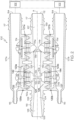
FIG. 2 is a side, longitudinal cross-sectional, plan view of the Venturi device ofFIG. 1 . -
FIG. 3 is a side, perspective view of an alternate embodiment of just the body of the Venturi device ofFIG. 2 . -
FIG. 4 is a side, longitudinal cross-sectional, plan view of another embodiment of a Venturi device. -
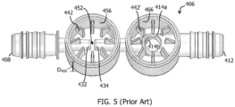
FIG. 5 is a side, perspective view of just the body of the Venturi device ofFIG. 4 . -
FIG. 6 is a side, perspective, exploded view of a Venturi device. -
FIG. 7 is a side, plan view of a first embodiment of a check valve insert, according to the present invention. -
FIG. 8 is a side, perspective view of a second embodiment of a check valve insert, not making part of the present invention, but useful to its understanding. -
FIG. 9 is a side, perspective view of a third embodiment of a check valve insert, not making part of the present invention, but useful to its understanding. -
FIG. 10 is a side, perspective view of a fourth embodiment of a check valve insert, not making part of the present invention, but useful to its understanding. -
FIG. 11 is a side, perspective view of a fifth embodiment of a check valve insert, not making part of the present invention, but useful to its understanding. -
FIG. 12 is a side, perspective view of a sixth embodiment of a check valve insert, not making part of the present invention, but useful to its understanding. -
FIG. 13 is a longitudinal, cross-section view of a stand-alone check valve having a check valve insert. - The following detailed description will illustrate the general principles of the invention, examples of which are additionally illustrated in the accompanying drawings. In the drawings, like reference numbers indicate identical or functionally similar elements.
- As used herein, "fluid" means any liquid, suspension, colloid, gas, plasma, or combinations thereof.
-
FIG. 1 is an external view of a Venturi device, generally identified byreference number 100, for use in an engine, for example, a vehicle's engine. The engine may be an internal combustion engine that includes a device requiring avacuum 102 represented inFIG. 2 . Check valves are normally employed in vehicle systems in the air flow lines, for example, between the intake manifold, downstream of the throttle, and the devices requiring vacuum. The engine and all its components and/or subsystems are not shown in the figures, with the exception of a few boxes included to represent specific components of the engine as identified herein, and it is understood that the engine components and/or subsystems may include any commonly found in vehicle engines. For example, a source of motive flow is fluidly connected to amotive section 116 of the Venturidevice 100, which may be atmospheric pressure or boosted pressure. While the embodiments in the figures are referred to as aspirators because themotive section 116 is connected to atmospheric pressure, the embodiments are not limited thereto. In other embodiments, themotive section 116 may be connected to boosted pressure, such as the pressures attributed to boosted air produced by a turbocharger, and as such the "aspirator" is now preferably referred to as an "ejector." - Referring to
FIGS. 1 and2 , the Venturidevice 100 is connected to adevice requiring vacuum 102, and the Venturidevice 100 creates vacuum for saiddevice 102 by the flow of air through apassageway 104, extending generally the length of thebody 106, designed to create the Venturi effect. Passageway 104 has four or more ports that are connectable to an engine or components connected thereto. The ports include: (1) amotive port 108, which may be connected to a source of clean air, e.g., from the engine intake air cleaner, that is positioned upstream of a throttle; (2 and 3) a pair ofsuction ports discharge outlet 112, which may be connected to an engine intake manifold downstream of the throttle of the engine; and, optionally, (5) one ormore bypass ports passageway 104 travels from the motive port 108 (high pressure) toward the discharge outlet 112 (low pressure). In the illustrated embodiment, thesuction ports port 154 and an optionalauxiliary port 115 viasuction housings ports 154 may function as inlets connecting the Venturi device to adevice requiring vacuum 102. In one embodiment, the device requiring vacuum may be one device connected to bothports 154, or two separate devices each connected to oneport 154 as shown inFIG. 2 . An additional device requiring vacuum may be connected to one or more of theauxiliary ports 115. Each of therespective ports connector feature 117 on the outer surface thereof for connecting the respective port to a hose or other component in the engine. - In
FIGS. 1 and2 , thebody 106 is connected to theupper suction housing 107a and to thelower suction housing 107b with sealingly tight connections. In the illustrated embodiment,upper housing portion 107a andlower housing portion 107b are identical aside from their attachment locations relative to thebody 106, butsuction housings suction housings body 106, are omitted). The designations of upper, lower, and middle portions are relative to the drawings as oriented on the page, for descriptive purposes, and are not limited to the illustrated orientation when utilized in an engine system. The upper and lower suction housings are joined to thebody 106, for example by sonic welding, heating, or other conventional methods for forming an airtight or fluidtight seal therebetween. - Still referring to
FIGS. 1 and2 , in the illustrated embodiment,check valves device 100 between thesuction housings respective suction ports bypass ports check valves Check valves suction ports application device 102. In one embodiment, thedevice requiring vacuum 102 is a vehicle brake boost device, a fuel vapor purging system, an automatic transmission, or pneumatic or hydraulic valve, but is not limited thereto. - The
check valves first valve seat body 106. Thefirst valve seat 124 defines thefirst suction port 110a, and thesecond valve seat 126 defines thesecond suction port 110b, which both allow for air flow communication withair passageway 104. InFIG. 2 , thefirst valve seat 124 includes a plurality of radially spacedfingers 142 and thesecond valve seat 126 includes a plurality of radially spacedfingers 144 extending into acavity check valves seal disc 111a, 111b. Thecheck valves second valve seat suction housings seal disc 111a, 111b can be seated, for example, in a closed position of the check valve. Similarly,check valves bypass ports check valves seal discs - The
body 106 definespassageway 104 along a central longitudinal axis B bisected by thesuction ports inner passageway 104 includes a first tapering portion 128 (also referred to herein as the motive cone) in themotive section 116 of thebody 106 coupled to a second tapering portion 129 (also referred to herein as the discharge cone) in thedischarge section 146 of thebody 106. Here, thefirst tapering portion 128 and the second taperingportion 129 are aligned end to end having themotive outlet end 132 facing thedischarge inlet end 134 and defining a Venturigap 152 therebetween, which defines a fluid junction placing thesuction ports motive section 116 and thedischarge section 146. The Venturigap 152 as used herein means the lineal distance of the void between themotive outlet end 132 and thedischarge inlet end 134. The interior surface of themotive outlet end 132 and thedischarge inlet end 134 are both ellipse-shaped but may alternately have a polygonal form or other curved form. - The
bypass ports second tapering section 129 adjacent to, but downstream of, thedischarge outlet end 136. Thebody 106 may thereafter, i.e., downstream of this intersection of the bypass port 114, continue with a cylindrically uniform inner diameter until it terminates at theaspirator outlet 112. In another embodiment (not shown), thebypass ports suction ports FIGS. 1 and2 , thesuction ports bypass ports suction ports bypass ports suction ports Venturi gap 152, also provides improved suction flow rate for a given motive flow and discharge pressure as compared to a system incorporating a single suction port 110 because the disclosed system provides greater capacity to utilize the Venturi effect created by the motive flow throughpassageway 104. - Referring now to
FIG. 3 , an alternate embodiment of the body of a Venturi device, generally designated 206, is disclosed. Thebody 206 defines a passageway generally equivalent topassage 104 described above and has a variety of ports including amotive port 208, a pair ofsuction ports discharge outlet 212, anddual bypass ports FIGS. 1 and2 , thebody 206 is mateable tosuction housings FIG. 2 . The body 306 further defines achamber 256 spacing thefirst suction port 210a and thesecond suction port 210b apart from one another by a distance D200. Themotive outlet end 232 extends into thechamber 256 at a position where thechamber 256 provides fluid flow around the entire outer surface of themotive outlet end 232, and thedischarge inlet end 234 extends into thechamber 256 at a position where thechamber 256 provides fluid flow around the entire outer surface of theinlet end 234. The width of theVenturi gap 252 tapers symmetrically generally proximate thefirst suction port 210a and thesecond suction port 210b (the widest points) toward a central point therebetween, as described in co-ownedU.S. Application 14/734,228, filed June 9, 2015 Venturi gap 252 is wider proximate both thefirst suction port 210a and thesecond suction port 210b than at a generally central point between the first andsecond suction ports - The
chamber 256 defined by the body 306 includes a plurality offingers 242 extending radially inward and axially away (upward in the figures) from the passageway of thebody 206. The plurality offingers 242 are arranged radially as protrusion from an inner wall of thechamber 256 in an orientation where immediately adjacent neighboring fingers are spaced a distance apart from one another. The plurality offingers 242 define a seat for a seal disc as part of check valve, such ascheck valve 120a. Similarly, thecheck valve 121a, if the bypass port(s) 214a is present, has achamber 266 defined by thebody 206 that includes a plurality of fingers 242' extending radially inward and radially away (upward in the drawings) from the passageway of thebody 206 that collectively define a seat for a seal disc. The plurality of fingers 242' are arranged radially as protrusion from an inner wall of thechamber 266 in an orientation where immediately adjacent neighboring fingers are spaced a distance apart from one another. Each of the plurality offingers 242, 242' has a base that is wider than at an apex thereof. - The apexes of the plurality of
fingers 242 collectively define the seat for the seal disc for an open position, and the apexes of fingers 242' define the seat for a second seal disc for an open position. In the embodiment ofFIG. 2 , sincecheck valves fingers 242 in the embodiment ofFIG. 3 include amirror image finger 244 beginning at its base and projecting axially away from the base and terminating at an apex. Themirror image fingers 244 are integral with thefingers 242. The apexes of themirror image fingers 244 collectively define the seat for anotherseal disc 111b. Similarly, the mirror image fingers 244', if the fingers 242' are present, are integral with the plurality of fingers 242', begin at the base thereof, and extend axially away from the base thereof (downward in the figures). The apexes of the plurality of mirror image fingers 244' define the seat forseal disc 111d. - Referring now to
FIGS. 4 and5 , an alternate embodiment of a Venturi device, generally designated 400, is disclosed. TheVenturi device 400 is connected to adevice requiring vacuum 102 and includes abody 406 definingpassageway 404 and having a variety of ports including amotive port 408, a pair ofsuction ports 410a, 410b, anaspirator outlet 412, asuction housing 407 connected to thebody 406 with fluidtight/airtight seals, for example by sonic welding, heating, or other conventional methods for forming such seals therebetween, and, optionally,dual bypass ports suction housing 407 and thebody 406, together,form check valve 420 and/or 421, which if present include aseal disc 411, 411', respectively. Additionally,Venturi device 400 includes afirst cap 409a and asecond cap 409b defining an end of thechamber 456 and an end ofchamber 466, respectively. The first andsecond caps Venturi device 400 not described below are understood to be analogous to those described above with respect to the other embodiments. - The
body 406 definespassageway 404 along a central longitudinal axis bisected by thesuction ports 410a, 410b. Theinner passageway 404 includes afirst tapering portion 428 and thesecond tapering portion 429 aligned end to end with themotive outlet end 432 facing thedischarge inlet end 434 and defining aVenturi gap 452 therebetween. Thebody 406 further defines achamber 456 spacing thefirst suction port 410a and the second suction port 410b apart from one another by a distance D400 labeled inFIG. 5 . Themotive outlet end 432 extends into thechamber 456 at a position where thechamber 456 provides fluid flow around the entire outer surface of themotive outlet end 432, and thedischarge inlet end 434 extends into thechamber 456 at a position where thechamber 456 provides fluid flow around the entire outer surface of theinlet end 434. - The
chamber 456 defined by thebody 406 includes a plurality offingers 442 extending radially inward and axially away (upward in the figures) from thepassageway 404 of thebody 406. The plurality offingers 442 are arranged radially as protrusion from an inner wall of thechamber 456 in an orientation where immediately adjacent neighboring fingers are spaced a distance apart from one another. The plurality offingers 442 define a seat for theseal disc 411 as part ofcheck valve 420. Similarly, thecheck valve 421, if the bypass port(s) 414a, 414b are present, has achamber 466 defined by thebody 406 that includes a plurality of fingers 442' extending radially inward and radially away (upward in the drawings) from thepassageway 404 of thebody 406 that collectively define a seat for the seal disc 411'. The plurality of fingers 442' are arranged radially as protrusion from an inner wall of thechamber 466 in an orientation where immediately adjacent neighboring fingers are spaced a distance apart from one another. Each of the plurality offingers 442, 442' has a base that is wider than at an apex thereof. The apexes of the plurality offingers 442 collectively define the seat for theseal disc 411 for an open position, and the apexes of fingers 442' define the seat for seal disc 411' for an open position. - The Venturi devices described above are very durable and effective for producing vacuum for an engine. Improvements, however, are always desirable, especially if the improvement can lengthen the lifetime wear of a component of the device. After much testing and trials, it has been found that the discontinuous or interrupted surface that the plurality of
fingers seal disc 111, 411 contributes stress to theseal disc 111, 411 over the life of the Venturi device. As such, an improvement has been developed, as shown inFIGS. 6-13 , that reduces the stress on theseal disk 511 by providing a continuous surface as thefirst valve seat 524 against which theseal disc 511 seats in an open position of the check valve. This improvement not only reduces the stress on the seal disc over the life of the Venturi device, it provides a reduction in air flow resistance or restriction as the air flows through the check valve. - Furthermore, by making the
first valve seat 524 part of acheck valve insert 505 additional advantages have been realized. Thecheck valve insert 505 can be made of a different material than thebody 506 and/or thesuction housing 507. The material selected for thecheck valve insert 505 is less abrasive and/or less rigid than the material selected for thebody 506 and/or thesuction housing 507. For example, thebody 506 and/or thesuction housing 507 may be made of a high glass fiber-filled plastic or a mineral filled plastic. In contrast, thecheck valve insert 505 may now be made of pure plastics (non-filled plastics) or rubbers, such as EPDM. Another advantage is the ability to select acheck valve insert 505 from a plurality of configurations (seeFIGS. 6-12 ) to tailor the performance characteristics of the Venturi device to the system in which it will operate. - Turning to
FIGS. 7-12 , variations of thecheck valve insert 505 are shown. Each of thecheck valve inserts 505a-505f define afirst seat 524 for an open position of a check valve unit, such as any of the check valve units in the Venturi devices disclosed herein or in a stand-alone check valve, such as the one inFIG. 13 . Eachcheck valve insert 505a-505f has anouter support 570 seatable in aninternal chamber check valve unit 500, 600 (FIGS. 6 and13 ). Theouter support 570 has anupper surface 571 and alower surface 572. Eachcheck valve insert 505a-505f has an innerannular ring 574 spaced radially inward from theouter support 570 by arib 576 that angles axially toward a central longitudinal axis C to position anupper surface 575 of the inner annular ring 574 a distance axially D1 (labeled inFIG. 7 ) beyond theupper surface 571 of the outer support. As shown inFIGS. 7 and 8 , the check valve insert 50 may have ten ribs connecting the innerannular ring 574 to theouter support 570. As shown inFIGS. 9-11 , thecheck valve insert 505 may have fourribs 576 connecting the innerannular ring 574 to theouter support 570. As shown inFIG.12 , thecheck valve insert 505 may have tworibs 576 connecting the innerannular ring 574 to theouter support 570. These are just example embodiments and any number of ribs are possible, including a single rib. - The
outer support 570 is illustrated inFIGS. 6-13 as an annular ring that is circular but is not limited thereto. In other embodiments, theouter support 570 may be oval or may be a polygonal-shaped ring. The innerannular ring 574 is typically circular in shape as shown inFIGS. 6 ,8 ,9 ,11, and 12 or is oval in shape as shown inFIG. 10 . The innerannular ring 574 in addition to being circular or oval in shape may have various configurations for theupper surface 575. In the embodiments illustrated inFIGS. 6 ,8 , and11 , not making part of the present invention, but useful to its understanding, theupper surface 575 is a continuous surface in one plane perpendicular to the central longitudinal axis C. In the embodiments illustrated inFIGS. 9, 10 , and12 , not making part of the present invention, but useful to its understanding, theupper surface 575 undulates with two opposingtroughs 579. In the embodiment, illustrated inFIG.7 , and according to the present invention, theupper surface 575 is angled downward and radially outward toward theouter support 570 over a minor arc extending 20 degrees up to 170 degrees along the innerannular ring 574, thereby defining aninclined surface portion 580 of the upper surface. - Turning now to
FIG. 6 , a Venturi device, generally designated 500, is disclosed that includes thecheck valve insert 505 described above. TheVenturi device 500 may be connected to a device requiring vacuum, in particular one in an engine system, and includes abody 506 defining an extending from amotive port 508 to adischarge port 512. Additional ports of thebody 506 include a pair ofsuction ports dual bypass ports suction port 510a andbypass port 514a (if present) are connected to asuction housing 407 with fluidtight/airtight seals, for example by sonic welding, heating, or other conventional methods for forming such seals. Thesuction housing 507 and thebody 506, together,form check valve 520 and/or 521, which if present, each include aseal disc 511. Thesuction port 510b andbypass port 514b may be connected to a second suction housing as shown inFIG. 2 , and if so, may each include acheck valve insert 505 and aseal disc 511 in the same manner ascheck valves FIG. 4 (without a check valve or check valve insert present). Components of theVenturi device 500 not described below are understood to be analogous to those described above with respect to the other embodiments. - The
body 506 has a first tapering portion and the second tapering portion aligned end to end with themotive outlet end 532 facing thedischarge inlet end 534 and defining aVenturi gap 552 therebetween. Thebody 506 further defines achamber 556 spacing thefirst suction port 510a and thesecond suction port 510b apart from one another by a distance D2 at positions that are generally opposite one another, but both in fluid communication with the Venturi gap. Themotive outlet end 532 extends into thechamber 556 at a position where thechamber 556 provides fluid flow around the entire outer surface of themotive outlet end 532, and thedischarge inlet end 534 extends into thechamber 556 at a position where thechamber 556 provides fluid flow around the entire outer surface of theinlet end 534. - The
chamber 556 andchamber 566 each have afirst shoulder 530 protruding inward to define a seat to receive and retain one of thecheck valve inserts 505a-505f. Alower surface 572 of thecheck valve insert 505 is seated against theshoulder 530 to retain thecheck valve insert 505 in a position a pre-selected distance between theVenturi gap 552 and thefirst suction port 510a orbypass port 514a, respectively, to place the open position for theseal disc 511 at a preselected location. Aseal disc 511 moveable within a chamber between an open position seated on thefirst valve seat 524 defined by the innerannular ring 575 of the firstcheck valve insert 505 and a closed position is also housed with each ofchambers seal disc 511 is translatable in response to a pressure difference across the opposing major surfaces of each seal disc itself. - Turning now to
FIG. 13 , a stand-alone check valve 600 is shown in an exploded view. The check valve 600 includes ahousing internal cavity 606 in the assembled position (assembled with a fluidtight/airtight seal) having apin 664 therein upon which is seated aseal disc 611 and defining afirst port 608 in fluid communication with theinternal cavity 606 and asecond port 612 in fluid communication with theinternal cavity 606, thereby defining a flow path from the first port through the chamber to the second port, or vice versa. Theinternal cavity 606 typically has larger dimensions than thefirst port 608 and thesecond port 612. In the illustrated embodiments, thefirst port 608 and thesecond port 612 are positioned opposite one another to define a generally linear flow path through the check valve 600, when theseal disc 611 is not present, but is not limited to this configuration. The portion of the housing defining theinternal cavity 606 includes an internalfirst seat 524 upon which the seal disc seats when the check valve is open and asecond seat 626 upon which the seal disc seats when the check valve is open. Here, thefirst seat 524 is defined by any of the check valve inserts 505 described herein, and thesecond seat 626 is one or more features on an inner surface of theinternal cavity 606. - The
internal cavity 606 has ashoulder 630 protruding inward that defines a seat for any other retaining feature to receive thecheck valve insert 505. Alower surface 572 of thecheck valve insert 505 is seated against theshoulder 630 to retain thecheck valve insert 505 in a preselected position within theinternal cavity 606 to place the open position for theseal disc 611 at a preselected location. Theseal disc 611 is moveable within theinternal cavity 606 between the open position seated on thefirst valve seat 524 defined by an innerannular ring 574 of thecheck valve insert 505 and a closed position seated on thesecond valve seat 626. Theseal disc 611 is translatable in response to a pressure differential across the opposing surfaces thereof. - In all embodiments, the
check valve insert 505 may be pressfit within the housing or may have a snapfit thereto. - The
seal disc first valve seat 524 of a check valve insert in an angled position relative to the central longitudinal axis C. In another embodiment, theseal disc upper surface 575 of the innerannular ring 574 of acheck valve insert 505. Theseal disc - The check valve insert as a separate and discrete component of the check valve is easier to manufacture, provides a more robust construction, and is an easier means to vary the construction of the check valve, i.e., changing the number of ribs or shape/contour of the inner annular ring. It improves the moldability of the check valve insert by reducing sink marks resulting from the injection molding process of plastics. Sink marks develop when material in the region of features such as ribs or bosses shrink more than material in the adjacent wall because of differential rates of cooling as a result of different thicknesses. Also, it improves the moldability of the lower body by removing features from the lower body that may have made it more difficult to lock core pins together. For example, it is easier to access the Venturi gap to lock core pins together, which assures that the motive and discharge ports are aligned, thereby providing for overall better performance of the Venturi device. Additionally, the check valve insert provides better support for the sealing disc with less section flow restriction because of the presence of the inner annular ring. The inner annular ring also enables the ribs to be thinner and fewer in number than individual fingers that defined the valve seat in the prior art.
Claims (14)
- A check valve insert (505) defining a first seat (524) for an open position of a check valve unit (500, 600), the check valve insert comprising:an outer support (570) seatable in an internal chamber of a check valve unit (500, 600) and having an upper surface (571) and a lower surface (572); andan inner annular ring (574) spaced radially inward from the outer support (570) by a rib (576) that angles axially toward a central longitudinal axis (C) to position an upper surface (575) of the inner annular ring (574) a distance axially beyond the upper surface (571) of the outer support (570);characterized in that the upper surface (575) of the inner annular ring (574) is angled downward and radially outward toward the outer support (570) over a minor arc extending 20 degrees up to 170 degrees along the inner annular ring, thereby defining an inclined surface portion (580) of the upper surface (575).
- The check valve insert of claim 1, wherein the outer support (570) is an annular ring or a polygonal-shaped ring.
- The check valve insert of claim 1, wherein the inner annular ring (574) is circular or oval in shape.
- The check valve insert of claim 1, wherein a plurality of circumferentially spaced apart ribs (576) space the inner annular ring (574) from the outer support (570).
- A check valve unit (500, 600) comprising:a two-part housing (506 and 507; 602a and 602b) comprising a first housing part defining an inlet port (508, 608) and a second housing part defining an outlet port (512, 612), wherein, when sealingly mated together, the first housing part and the second housing part collectively define a chamber (556 or 566; 606) in fluid communication with the inlet port and the outlet port, thereby defining a flow path from the inlet port through the chamber to the outlet port, wherein the chamber (556 or 566; 606) defines a seal seat (626) for a closed position and has a shoulder (530; 630) protruding inward into the chamber;a check valve insert (505) according to any of claims 1-4 seated on the shoulder (530; 630) in the chamber; anda seal disc (511; 611) translatable linearly within the chamber (556 or 566; 606) in response to a pressure difference across the seal disc (511; 611) itself to move the seal disc from an open position seated on the upper surface (575) of the inner annular ring (574) of the check valve insert (505) to the closed position seated solely against the seal seat (626) of the chamber.
- The check valve unit of claim 5, wherein the outlet port is a Venturi gap (552) of a Venturi device (500).
- The check valve unit of claim 5, wherein the outlet port is a bypass port (514a) of a Venturi device (500).
- The check valve unit of claim 8, wherein the bypass port (514a) is positioned downstream of a Venturi gap (552).
- A Venturi device (500) comprising:a body (506) defining a passageway having a motive section (116) and a discharge section (146) spaced a distance apart from one another to define a Venturi gap (552), both of which converge toward the Venturi gap (552), and defining a chamber (556) housing the Venturi gap (552) and having a first suction port (510a) in fluid communication with the Venturi gap (552); wherein the chamber (556) has a first shoulder (530) protruding inward and positioned a pre-selected distance between the Venturi gap (552) and the first suction port (510a);a first check valve insert (505) according to any of claims 1-4 seated on the shoulder (530) in the chamber (556); anda first seal disc (511) moveable within the chamber (556) between an open position seated on the upper surface (575) of the inner annular ring (574) of the first check valve insert (505) and a closed position; wherein the first seal disc (511) is translatable in response to a pressure difference across the first seal disc (511) itself; anda first suction housing (507) sealingly connected to the first suction port (510a) to collectively form a first check valve (520); wherein the suction housing (507) defines a valve seat for the closed position.
- The Venturi device of claim 9, wherein the body (106) further defines a second suction port (510b) in fluid communication with the Venturi gap (552), and a cap (409b) sealingly connected to the second suction port (510b) of the body or a second suction housing (107b) sealingly connected to the second suction port (510b) of the body to collectively form a second check valve (521).
- The Venturi device of claim 9, wherein the chamber (556) has a second shoulder protruding inward and positioned a pre-selected distance between the Venturi gap (552) and the second suction port (510b), and a second check valve insert (505) seated on the second shoulder in the chamber, the second check valve insert (505) comprising:an outer support (570) seatable in the chamber and having an upper surface (571) and a lower surface (572); andan inner annular ring (524) spaced radially inward from the outer support (570) by a rib (576) that angles axially toward a central longitudinal axis (C) to position an upper surface (575) of the inner annular ring (524) a distance axially beyond the upper surface (571) of the outer support (570).
- The Venturi device of claim 11, further comprising a second seal disc (511) moveable within the second check valve chamber (566) between an open position seated on the upper surface of the inner annular ring (575) of the second check valve (505) insert and a closed position; wherein the second seal disc (511) is translatable in response to a pressure difference across the second seal disc itself.
- The Venturi device of claim 9, wherein an outlet end (532) of the motive section extends into the chamber (556) defined by the body (506) at a position where the chamber provides fluid flow around the entire outer surface of the outlet end, and an inlet end (534) of the discharge section extends into the chamber (556) at a position where the chamber provides fluid flow around the entire outer surface of the inlet end of the discharge section.
- The Venturi device of claim 9, wherein the body (506) further defines a bypass port (514a) downstream of the first suction port (510a).
Applications Claiming Priority (2)
| Application Number | Priority Date | Filing Date | Title |
|---|---|---|---|
| US201862661165P | 2018-04-23 | 2018-04-23 | |
| PCT/US2019/028726 WO2019209828A1 (en) | 2018-04-23 | 2019-04-23 | A check valve insert defining an open position and check valves having same |
Publications (3)
| Publication Number | Publication Date |
|---|---|
| EP3784939A1 EP3784939A1 (en) | 2021-03-03 |
| EP3784939A4 EP3784939A4 (en) | 2021-11-24 |
| EP3784939B1 true EP3784939B1 (en) | 2023-07-12 |
Family
ID=68236840
Family Applications (1)
| Application Number | Title | Priority Date | Filing Date |
|---|---|---|---|
| EP19793160.3A Active EP3784939B1 (en) | 2018-04-23 | 2019-04-23 | A check valve insert defining an open position and check valves having same |
Country Status (6)
| Country | Link |
|---|---|
| US (1) | US11486504B2 (en) |
| EP (1) | EP3784939B1 (en) |
| JP (1) | JP7320176B2 (en) |
| CN (1) | CN112020623B (en) |
| BR (1) | BR112020021807A2 (en) |
| WO (1) | WO2019209828A1 (en) |
Families Citing this family (13)
| Publication number | Priority date | Publication date | Assignee | Title |
|---|---|---|---|---|
| US10914412B2 (en) | 2018-06-28 | 2021-02-09 | Watts Regulator Co. | Backflow prevention assembly having a variable lay-length and orientation |
| EP3705866B1 (en) | 2019-03-08 | 2023-09-20 | WATTS INDUSTRIES ITALIA S.r.l. | Differential pressure sensor with magnetic dial |
| US11815424B2 (en) * | 2019-05-08 | 2023-11-14 | Watts Regulator Co. | Backflow prevention system test cock with a fluid sensor |
| US11795666B2 (en) | 2019-05-08 | 2023-10-24 | Watts Regulator Co. | Wireless communication system within a mechanical room |
| US11370016B2 (en) * | 2019-05-23 | 2022-06-28 | Raytheon Technologies Corporation | Assembly and method of forming gas turbine engine components |
| EP3835494A1 (en) | 2019-12-10 | 2021-06-16 | Watts Regulator Co. | System for monitoring backflow preventer condition |
| US11585076B2 (en) | 2020-01-24 | 2023-02-21 | Watts Regulator Co. | Apparatus and method for valve cartridge extraction |
| US11719352B2 (en) | 2020-08-17 | 2023-08-08 | Watts Regulator Co. | Check cover assemblies for backflow prevention assemblies with integrated test cock protection shroud |
| US11773992B2 (en) | 2020-08-17 | 2023-10-03 | Watts Regulator Co. | Backflow prevention assembly with a linkage |
| US11739507B2 (en) | 2020-12-09 | 2023-08-29 | Watts Regulator Co. | Test cock with integrated extraction tool |
| US11614098B2 (en) * | 2020-12-24 | 2023-03-28 | Dayco Ip Holdings, Llc | Devices for producing vacuum using the Venturi effect having a solid fletch |
| US11408380B2 (en) * | 2020-12-24 | 2022-08-09 | Dayco Ip Holdings, Llc | Devices for producing vacuum using the Venturi effect having a hollow fletch |
| USD1021000S1 (en) | 2021-08-17 | 2024-04-02 | Watts Regulator Co. | Valve assembly and body for same |
Family Cites Families (32)
| Publication number | Priority date | Publication date | Assignee | Title |
|---|---|---|---|---|
| US1593519A (en) * | 1925-04-02 | 1926-07-20 | Malery E Underwood | Check valve |
| GB829560A (en) * | 1956-03-09 | 1960-03-02 | Durabla Mfg Company | Improvements in valves for compressible fluids |
| US4535808A (en) * | 1983-07-08 | 1985-08-20 | Dicken Manufacturing Company | Check valve |
| GB8421514D0 (en) * | 1984-08-24 | 1984-09-26 | Godiva Fire Pumps Ltd | Flow control valve |
| US4729401A (en) | 1987-01-29 | 1988-03-08 | Burron Medical Inc. | Aspiration assembly having dual co-axial check valves |
| US5113900A (en) * | 1991-01-30 | 1992-05-19 | Bridge Products, Inc. | Check valve with quick lock attachment feature |
| US5535785A (en) * | 1994-09-08 | 1996-07-16 | Nypro, Inc. | Luer-activated check valve |
| EP1093555B1 (en) | 1998-07-09 | 2003-04-09 | Parker Hannifin Corporation | Check valve |
| US6308731B1 (en) * | 1999-06-25 | 2001-10-30 | Itz Corporation | Vent valve |
| US6220282B1 (en) * | 1999-11-03 | 2001-04-24 | Hunter Innovations, Inc. | Backflow prevention apparatus |
| AT10159U1 (en) | 2007-05-16 | 2008-10-15 | Alutech Gmbh | FUEL TANK FOR A VEHICLE |
| DE102008029822A1 (en) * | 2008-06-25 | 2009-12-31 | Gardner Denver Schopfheim Gmbh | pump |
| US20140150905A1 (en) * | 2010-02-04 | 2014-06-05 | Nyloncraft, Inc. | Check valve |
| US20110186151A1 (en) | 2010-02-04 | 2011-08-04 | Bernard Joseph Sparazynski | Check valve |
| US20130092261A1 (en) * | 2011-10-13 | 2013-04-18 | Flomatic Corporation | Check valve |
| US9032992B2 (en) * | 2011-10-13 | 2015-05-19 | Flomatic Corporation | Check valve |
| EP2906860B1 (en) * | 2012-10-12 | 2017-09-20 | Yazykov, Andrey Yurievich | Check valve |
| CN103899796B (en) * | 2012-12-31 | 2016-05-18 | 中钢集团衡阳重机有限公司 | Check valve |
| RU2637620C2 (en) * | 2013-03-16 | 2017-12-05 | Поли Медикьюэ Лимитед | Valve for transfer unit |
| EP3055597B1 (en) | 2013-10-08 | 2019-02-27 | Dayco IP Holdings, LLC | Noise attenuation in a check valve unit or apparatus for producing vacuum |
| KR102173205B1 (en) | 2014-01-20 | 2020-11-03 | 데이코 아이피 홀딩스 엘엘시 | Check valve with improved sealing member |
| US10107240B2 (en) | 2014-04-04 | 2018-10-23 | Dayco Ip Holdings, Llc | Check valves and Venturi devices having the same |
| CN108361438B (en) | 2014-04-04 | 2020-09-04 | 戴科知识产权控股有限责任公司 | Bypass check valve and venturi device having the same |
| JP6654148B2 (en) * | 2014-06-09 | 2020-02-26 | デイコ アイピー ホールディングス, エルエルシーDayco Ip Holdings, Llc | Venturi device with dual venturi flow path |
| JP6756699B2 (en) * | 2014-07-10 | 2020-09-16 | デイコ アイピー ホールディングス,エルエルシーDayco Ip Holdings,Llc | Dual venturi device |
| JP6081411B2 (en) * | 2014-07-22 | 2017-02-15 | リンナイ株式会社 | Check valve |
| KR101704273B1 (en) * | 2015-10-26 | 2017-02-07 | 현대자동차주식회사 | Noise reducing device for vacuum pressure line of brake booster |
| JP6539196B2 (en) | 2015-12-14 | 2019-07-03 | 積水化学工業株式会社 | Check valve device and rehabilitating method of existing pipe |
| US9885422B2 (en) * | 2015-12-15 | 2018-02-06 | International Valve Corporation | Check valve having a friction free replaceable valve insert check assembly |
| WO2018057692A1 (en) * | 2016-09-21 | 2018-03-29 | Dayco Ip Holdings, Llc | Valve gate within a venturi gap of a venturi device for producing vacuum |
| CN106838386B (en) * | 2017-03-06 | 2019-10-29 | 合肥通用机械研究院 | It is a kind of can on-line maintenance axial flow type check valve |
| CN107340213A (en) * | 2017-09-12 | 2017-11-10 | 陈刚 | A kind of portable dust pollution detection means |
-
2019
- 2019-04-23 BR BR112020021807-3A patent/BR112020021807A2/en unknown
- 2019-04-23 CN CN201980027751.3A patent/CN112020623B/en active Active
- 2019-04-23 JP JP2020558977A patent/JP7320176B2/en active Active
- 2019-04-23 EP EP19793160.3A patent/EP3784939B1/en active Active
- 2019-04-23 US US16/391,941 patent/US11486504B2/en active Active
- 2019-04-23 WO PCT/US2019/028726 patent/WO2019209828A1/en unknown
Also Published As
| Publication number | Publication date |
|---|---|
| JP7320176B2 (en) | 2023-08-03 |
| EP3784939A1 (en) | 2021-03-03 |
| CN112020623A (en) | 2020-12-01 |
| BR112020021807A2 (en) | 2021-02-23 |
| JP2021524002A (en) | 2021-09-09 |
| US20190323618A1 (en) | 2019-10-24 |
| US11486504B2 (en) | 2022-11-01 |
| CN112020623B (en) | 2023-08-15 |
| WO2019209828A1 (en) | 2019-10-31 |
| KR20210002510A (en) | 2021-01-08 |
| EP3784939A4 (en) | 2021-11-24 |
Similar Documents
| Publication | Publication Date | Title |
|---|---|---|
| EP3784939B1 (en) | A check valve insert defining an open position and check valves having same | |
| US10724550B2 (en) | Venturi devices with dual Venturi flow paths | |
| US10190549B2 (en) | Check valves and venturi devices having the same | |
| EP3097331B1 (en) | Check valve with improved sealing member | |
| US10473235B2 (en) | Bypass check valve and Venturi having same | |
| CN109715998B (en) | Venturi device for generating vacuum and system thereof | |
| EP3468847B1 (en) | Check valves and venturi devices having the same | |
| KR102667590B1 (en) | Check valve insert defining an open position and a check valve having the same | |
| CN109311466B (en) | Bypass valve in device for generating vacuum |
Legal Events
| Date | Code | Title | Description |
|---|---|---|---|
| STAA | Information on the status of an ep patent application or granted ep patent |
Free format text: STATUS: THE INTERNATIONAL PUBLICATION HAS BEEN MADE |
|
| STAA | Information on the status of an ep patent application or granted ep patent |
Free format text: STATUS: THE INTERNATIONAL PUBLICATION HAS BEEN MADE |
|
| PUAI | Public reference made under article 153(3) epc to a published international application that has entered the european phase |
Free format text: ORIGINAL CODE: 0009012 |
|
| STAA | Information on the status of an ep patent application or granted ep patent |
Free format text: STATUS: REQUEST FOR EXAMINATION WAS MADE |
|
| 17P | Request for examination filed |
Effective date: 20201120 |
|
| AK | Designated contracting states |
Kind code of ref document: A1 Designated state(s): AL AT BE BG CH CY CZ DE DK EE ES FI FR GB GR HR HU IE IS IT LI LT LU LV MC MK MT NL NO PL PT RO RS SE SI SK SM TR |
|
| AX | Request for extension of the european patent |
Extension state: BA ME |
|
| DAV | Request for validation of the european patent (deleted) | ||
| DAX | Request for extension of the european patent (deleted) | ||
| A4 | Supplementary search report drawn up and despatched |
Effective date: 20211022 |
|
| RIC1 | Information provided on ipc code assigned before grant |
Ipc: F16K 15/14 20060101ALI20211018BHEP Ipc: F04F 5/14 20060101ALI20211018BHEP Ipc: F02M 35/10 20060101ALI20211018BHEP Ipc: B60T 13/72 20060101ALI20211018BHEP Ipc: F16K 3/02 20060101ALI20211018BHEP Ipc: F16K 15/00 20060101ALI20211018BHEP Ipc: F16K 27/04 20060101ALI20211018BHEP Ipc: F16K 47/14 20060101AFI20211018BHEP |
|
| RAP3 | Party data changed (applicant data changed or rights of an application transferred) |
Owner name: DAYCO IP HOLDINGS, LLC |
|
| REG | Reference to a national code |
Ref country code: DE Ref legal event code: R079 Ref document number: 602019032685 Country of ref document: DE Free format text: PREVIOUS MAIN CLASS: F16K0047140000 Ipc: F04F0005220000 Ref country code: DE Free format text: PREVIOUS MAIN CLASS: F16K0047140000 |
|
| GRAP | Despatch of communication of intention to grant a patent |
Free format text: ORIGINAL CODE: EPIDOSNIGR1 |
|
| STAA | Information on the status of an ep patent application or granted ep patent |
Free format text: STATUS: GRANT OF PATENT IS INTENDED |
|
| RIC1 | Information provided on ipc code assigned before grant |
Ipc: F02M 35/10 19680901ALI20230112BHEP Ipc: F16K 27/02 19680901ALI20230112BHEP Ipc: F16K 15/14 19680901ALI20230112BHEP Ipc: F16K 15/08 19680901ALI20230112BHEP Ipc: F16K 15/02 19680901ALI20230112BHEP Ipc: F04F 5/46 19680901ALI20230112BHEP Ipc: F04F 5/22 19680901AFI20230112BHEP |
|
| INTG | Intention to grant announced |
Effective date: 20230202 |
|
| GRAS | Grant fee paid |
Free format text: ORIGINAL CODE: EPIDOSNIGR3 |
|
| GRAA | (expected) grant |
Free format text: ORIGINAL CODE: 0009210 |
|
| STAA | Information on the status of an ep patent application or granted ep patent |
Free format text: STATUS: THE PATENT HAS BEEN GRANTED |
|
| P01 | Opt-out of the competence of the unified patent court (upc) registered |
Effective date: 20230522 |
|
| AK | Designated contracting states |
Kind code of ref document: B1 Designated state(s): AL AT BE BG CH CY CZ DE DK EE ES FI FR GB GR HR HU IE IS IT LI LT LU LV MC MK MT NL NO PL PT RO RS SE SI SK SM TR |
|
| REG | Reference to a national code |
Ref country code: CH Ref legal event code: EP |
|
| REG | Reference to a national code |
Ref country code: DE Ref legal event code: R096 Ref document number: 602019032685 Country of ref document: DE |
|
| REG | Reference to a national code |
Ref country code: IE Ref legal event code: FG4D |
|
| REG | Reference to a national code |
Ref country code: LT Ref legal event code: MG9D |
|
| REG | Reference to a national code |
Ref country code: NL Ref legal event code: MP Effective date: 20230712 |
|
| REG | Reference to a national code |
Ref country code: AT Ref legal event code: MK05 Ref document number: 1587460 Country of ref document: AT Kind code of ref document: T Effective date: 20230712 |
|
| PG25 | Lapsed in a contracting state [announced via postgrant information from national office to epo] |
Ref country code: NL Free format text: LAPSE BECAUSE OF FAILURE TO SUBMIT A TRANSLATION OF THE DESCRIPTION OR TO PAY THE FEE WITHIN THE PRESCRIBED TIME-LIMIT Effective date: 20230712 |
|
| PG25 | Lapsed in a contracting state [announced via postgrant information from national office to epo] |
Ref country code: GR Free format text: LAPSE BECAUSE OF FAILURE TO SUBMIT A TRANSLATION OF THE DESCRIPTION OR TO PAY THE FEE WITHIN THE PRESCRIBED TIME-LIMIT Effective date: 20231013 |
|
| PG25 | Lapsed in a contracting state [announced via postgrant information from national office to epo] |
Ref country code: ES Free format text: LAPSE BECAUSE OF FAILURE TO SUBMIT A TRANSLATION OF THE DESCRIPTION OR TO PAY THE FEE WITHIN THE PRESCRIBED TIME-LIMIT Effective date: 20230712 |
|
| PG25 | Lapsed in a contracting state [announced via postgrant information from national office to epo] |
Ref country code: IS Free format text: LAPSE BECAUSE OF FAILURE TO SUBMIT A TRANSLATION OF THE DESCRIPTION OR TO PAY THE FEE WITHIN THE PRESCRIBED TIME-LIMIT Effective date: 20231112 |
|
| PG25 | Lapsed in a contracting state [announced via postgrant information from national office to epo] |
Ref country code: SE Free format text: LAPSE BECAUSE OF FAILURE TO SUBMIT A TRANSLATION OF THE DESCRIPTION OR TO PAY THE FEE WITHIN THE PRESCRIBED TIME-LIMIT Effective date: 20230712 Ref country code: RS Free format text: LAPSE BECAUSE OF FAILURE TO SUBMIT A TRANSLATION OF THE DESCRIPTION OR TO PAY THE FEE WITHIN THE PRESCRIBED TIME-LIMIT Effective date: 20230712 Ref country code: PT Free format text: LAPSE BECAUSE OF FAILURE TO SUBMIT A TRANSLATION OF THE DESCRIPTION OR TO PAY THE FEE WITHIN THE PRESCRIBED TIME-LIMIT Effective date: 20231113 Ref country code: NO Free format text: LAPSE BECAUSE OF FAILURE TO SUBMIT A TRANSLATION OF THE DESCRIPTION OR TO PAY THE FEE WITHIN THE PRESCRIBED TIME-LIMIT Effective date: 20231012 Ref country code: LV Free format text: LAPSE BECAUSE OF FAILURE TO SUBMIT A TRANSLATION OF THE DESCRIPTION OR TO PAY THE FEE WITHIN THE PRESCRIBED TIME-LIMIT Effective date: 20230712 Ref country code: LT Free format text: LAPSE BECAUSE OF FAILURE TO SUBMIT A TRANSLATION OF THE DESCRIPTION OR TO PAY THE FEE WITHIN THE PRESCRIBED TIME-LIMIT Effective date: 20230712 Ref country code: IS Free format text: LAPSE BECAUSE OF FAILURE TO SUBMIT A TRANSLATION OF THE DESCRIPTION OR TO PAY THE FEE WITHIN THE PRESCRIBED TIME-LIMIT Effective date: 20231112 Ref country code: HR Free format text: LAPSE BECAUSE OF FAILURE TO SUBMIT A TRANSLATION OF THE DESCRIPTION OR TO PAY THE FEE WITHIN THE PRESCRIBED TIME-LIMIT Effective date: 20230712 Ref country code: GR Free format text: LAPSE BECAUSE OF FAILURE TO SUBMIT A TRANSLATION OF THE DESCRIPTION OR TO PAY THE FEE WITHIN THE PRESCRIBED TIME-LIMIT Effective date: 20231013 Ref country code: FI Free format text: LAPSE BECAUSE OF FAILURE TO SUBMIT A TRANSLATION OF THE DESCRIPTION OR TO PAY THE FEE WITHIN THE PRESCRIBED TIME-LIMIT Effective date: 20230712 Ref country code: ES Free format text: LAPSE BECAUSE OF FAILURE TO SUBMIT A TRANSLATION OF THE DESCRIPTION OR TO PAY THE FEE WITHIN THE PRESCRIBED TIME-LIMIT Effective date: 20230712 Ref country code: AT Free format text: LAPSE BECAUSE OF FAILURE TO SUBMIT A TRANSLATION OF THE DESCRIPTION OR TO PAY THE FEE WITHIN THE PRESCRIBED TIME-LIMIT Effective date: 20230712 |
|
| PG25 | Lapsed in a contracting state [announced via postgrant information from national office to epo] |
Ref country code: PL Free format text: LAPSE BECAUSE OF FAILURE TO SUBMIT A TRANSLATION OF THE DESCRIPTION OR TO PAY THE FEE WITHIN THE PRESCRIBED TIME-LIMIT Effective date: 20230712 |
|
| PG25 | Lapsed in a contracting state [announced via postgrant information from national office to epo] |
Ref country code: SM Free format text: LAPSE BECAUSE OF FAILURE TO SUBMIT A TRANSLATION OF THE DESCRIPTION OR TO PAY THE FEE WITHIN THE PRESCRIBED TIME-LIMIT Effective date: 20230712 Ref country code: RO Free format text: LAPSE BECAUSE OF FAILURE TO SUBMIT A TRANSLATION OF THE DESCRIPTION OR TO PAY THE FEE WITHIN THE PRESCRIBED TIME-LIMIT Effective date: 20230712 Ref country code: EE Free format text: LAPSE BECAUSE OF FAILURE TO SUBMIT A TRANSLATION OF THE DESCRIPTION OR TO PAY THE FEE WITHIN THE PRESCRIBED TIME-LIMIT Effective date: 20230712 Ref country code: DK Free format text: LAPSE BECAUSE OF FAILURE TO SUBMIT A TRANSLATION OF THE DESCRIPTION OR TO PAY THE FEE WITHIN THE PRESCRIBED TIME-LIMIT Effective date: 20230712 Ref country code: CZ Free format text: LAPSE BECAUSE OF FAILURE TO SUBMIT A TRANSLATION OF THE DESCRIPTION OR TO PAY THE FEE WITHIN THE PRESCRIBED TIME-LIMIT Effective date: 20230712 Ref country code: SK Free format text: LAPSE BECAUSE OF FAILURE TO SUBMIT A TRANSLATION OF THE DESCRIPTION OR TO PAY THE FEE WITHIN THE PRESCRIBED TIME-LIMIT Effective date: 20230712 |
|
| PLBE | No opposition filed within time limit |
Free format text: ORIGINAL CODE: 0009261 |
|
| STAA | Information on the status of an ep patent application or granted ep patent |
Free format text: STATUS: NO OPPOSITION FILED WITHIN TIME LIMIT |