EP3782509A1 - Système de soins personnels avec un ensemble d'unités fonctionnelles - Google Patents
Système de soins personnels avec un ensemble d'unités fonctionnelles Download PDFInfo
- Publication number
- EP3782509A1 EP3782509A1 EP19192763.1A EP19192763A EP3782509A1 EP 3782509 A1 EP3782509 A1 EP 3782509A1 EP 19192763 A EP19192763 A EP 19192763A EP 3782509 A1 EP3782509 A1 EP 3782509A1
- Authority
- EP
- European Patent Office
- Prior art keywords
- functional units
- main body
- motor
- vibration
- personal care
- Prior art date
- Legal status (The legal status is an assumption and is not a legal conclusion. Google has not performed a legal analysis and makes no representation as to the accuracy of the status listed.)
- Withdrawn
Links
- 238000000034 method Methods 0.000 claims description 15
- 230000001815 facial effect Effects 0.000 claims description 6
- 230000001680 brushing effect Effects 0.000 claims description 5
- 230000006870 function Effects 0.000 claims description 4
- 238000004590 computer program Methods 0.000 claims description 3
- 238000012545 processing Methods 0.000 claims description 3
- 238000005259 measurement Methods 0.000 description 9
- 238000013459 approach Methods 0.000 description 4
- 238000001514 detection method Methods 0.000 description 4
- 238000001228 spectrum Methods 0.000 description 4
- 101100129500 Caenorhabditis elegans max-2 gene Proteins 0.000 description 2
- 230000008901 benefit Effects 0.000 description 2
- 238000004891 communication Methods 0.000 description 2
- 230000035617 depilation Effects 0.000 description 2
- 238000013461 design Methods 0.000 description 2
- 238000012986 modification Methods 0.000 description 2
- 230000004048 modification Effects 0.000 description 2
- 241000549893 Carphochaete Species 0.000 description 1
- 230000001133 acceleration Effects 0.000 description 1
- 238000006243 chemical reaction Methods 0.000 description 1
- 238000004140 cleaning Methods 0.000 description 1
- 230000008878 coupling Effects 0.000 description 1
- 238000010168 coupling process Methods 0.000 description 1
- 238000005859 coupling reaction Methods 0.000 description 1
- 230000001419 dependent effect Effects 0.000 description 1
- 230000000694 effects Effects 0.000 description 1
- 230000005484 gravity Effects 0.000 description 1
- 230000003287 optical effect Effects 0.000 description 1
- 230000008569 process Effects 0.000 description 1
- 239000000344 soap Substances 0.000 description 1
- 238000012546 transfer Methods 0.000 description 1
- XLYOFNOQVPJJNP-UHFFFAOYSA-N water Substances O XLYOFNOQVPJJNP-UHFFFAOYSA-N 0.000 description 1
Images


Classifications
-
- B—PERFORMING OPERATIONS; TRANSPORTING
- B26—HAND CUTTING TOOLS; CUTTING; SEVERING
- B26B—HAND-HELD CUTTING TOOLS NOT OTHERWISE PROVIDED FOR
- B26B19/00—Clippers or shavers operating with a plurality of cutting edges, e.g. hair clippers, dry shavers
- B26B19/12—Clippers or shavers operating with a plurality of cutting edges, e.g. hair clippers, dry shavers of the oscillating- cutter type; Cutting heads therefor; Cutters therefor
-
- A—HUMAN NECESSITIES
- A46—BRUSHWARE
- A46B—BRUSHES
- A46B13/00—Brushes with driven brush bodies or carriers
- A46B13/02—Brushes with driven brush bodies or carriers power-driven carriers
-
- A—HUMAN NECESSITIES
- A46—BRUSHWARE
- A46B—BRUSHES
- A46B15/00—Other brushes; Brushes with additional arrangements
- A46B15/0002—Arrangements for enhancing monitoring or controlling the brushing process
- A46B15/0004—Arrangements for enhancing monitoring or controlling the brushing process with a controlling means
-
- A—HUMAN NECESSITIES
- A46—BRUSHWARE
- A46B—BRUSHES
- A46B5/00—Brush bodies; Handles integral with brushware
- A46B5/0095—Removable or interchangeable brush heads
-
- A—HUMAN NECESSITIES
- A46—BRUSHWARE
- A46B—BRUSHES
- A46B7/00—Bristle carriers arranged in the brush body
- A46B7/04—Bristle carriers arranged in the brush body interchangeably removable bristle carriers
-
- B—PERFORMING OPERATIONS; TRANSPORTING
- B26—HAND CUTTING TOOLS; CUTTING; SEVERING
- B26B—HAND-HELD CUTTING TOOLS NOT OTHERWISE PROVIDED FOR
- B26B19/00—Clippers or shavers operating with a plurality of cutting edges, e.g. hair clippers, dry shavers
- B26B19/38—Details of, or accessories for, hair clippers, or dry shavers, e.g. housings, casings, grips, guards
- B26B19/3806—Accessories
- B26B19/3813—Attachments
-
- B—PERFORMING OPERATIONS; TRANSPORTING
- B26—HAND CUTTING TOOLS; CUTTING; SEVERING
- B26B—HAND-HELD CUTTING TOOLS NOT OTHERWISE PROVIDED FOR
- B26B19/00—Clippers or shavers operating with a plurality of cutting edges, e.g. hair clippers, dry shavers
- B26B19/38—Details of, or accessories for, hair clippers, or dry shavers, e.g. housings, casings, grips, guards
- B26B19/3873—Electric features; Charging; Computing devices
- B26B19/388—Sensors; Control
-
- A—HUMAN NECESSITIES
- A46—BRUSHWARE
- A46B—BRUSHES
- A46B2200/00—Brushes characterized by their functions, uses or applications
- A46B2200/10—For human or animal care
- A46B2200/104—Hair brush
-
- B—PERFORMING OPERATIONS; TRANSPORTING
- B26—HAND CUTTING TOOLS; CUTTING; SEVERING
- B26B—HAND-HELD CUTTING TOOLS NOT OTHERWISE PROVIDED FOR
- B26B19/00—Clippers or shavers operating with a plurality of cutting edges, e.g. hair clippers, dry shavers
- B26B19/02—Clippers or shavers operating with a plurality of cutting edges, e.g. hair clippers, dry shavers of the reciprocating-cutter type
- B26B19/04—Cutting heads therefor; Cutters therefor; Securing equipment thereof
-
- B—PERFORMING OPERATIONS; TRANSPORTING
- B26—HAND CUTTING TOOLS; CUTTING; SEVERING
- B26B—HAND-HELD CUTTING TOOLS NOT OTHERWISE PROVIDED FOR
- B26B19/00—Clippers or shavers operating with a plurality of cutting edges, e.g. hair clippers, dry shavers
- B26B19/14—Clippers or shavers operating with a plurality of cutting edges, e.g. hair clippers, dry shavers of the rotary-cutter type; Cutting heads therefor; Cutters therefor
Definitions
- This invention relates to personal care systems, in particular having a set of different functional units which may be selectively attached to, and detached from, a shared main body.
- Modern personal care appliances such as shavers, hair trimmers, female depilation devices, etc. are often modular devices where different functional units can be selectively attached to a main body. Examples of such functional units are shaving units, trimmer modules, beard styler modules, (facial) cleaning brushes, etc.
- Such devices are also becoming smarter in the sense that they allow different device settings and provide the user with status feedback via a user interface. For these functions to work optimally, it is often useful or even necessary to know which functional unit is currently attached to the main body.
- WO 2018/192788 discloses a personal care device in which a treatment head may be identified based on the motor current drawn resulting from the use of the treatment head. However, this may not give accurate results and hence not enable reliable identification if there is a significant number of treatment heads, for example with similar motor current characteristics.
- a personal care device drive unit comprising:
- the personal care device drive unit uses vibration sensing and motor current sensing to generate an output which is associated with a selected one of the different functional units.
- the functional units are for example personal care accessories for attachment to the main body.
- the output signal is "associated with" the selected (i.e. connected) functional unit in that the output signal is selected as one which is relevant to that particular functional unit. It may be a control signal for controlling the functional unit in a particular way, or for controlling another component, e.g. an output device, to present information relating to the functional unit.
- the output signal may control a display to make the display provide identification of the identified functional component, or it may make the display present a set of options to a user relating to that functional unit.
- the personal care device drive unit thus identifies a type of functional unit (out of a possible set) connected to a main body of the personal care device drive unit. The output signal may then automatically control the identified functional unit to be driven, by the motor, in a suitable way.
- both vibration sensing and current sensing which detects the electrical load resulting from the functional unit
- Some units may use a rotary motion, and therefore induce only a small (or no) amount of vibration.
- Other functional units may use a reciprocating movement, so that vibrations are induced.
- vibration and motor drive current i.e. the load seen by the motor
- the detection accuracy can be greatly improved.
- the controller may comprise a memory adapted to store a plurality of data sets, wherein:
- a data set is associated with each functional unit, and the data set is selected based on which functional unit has been identified as being connected to the main body.
- the personal care device drive unit may further comprise a speed feedback control system adapted to control a drive speed of the motor.
- vibrations caused by the motor itself will give rise to known vibration parameters, which can then be filtered or ignored as not relating to a connected functional unit. Additionally, vibrating functional units that vibrate with frequencies close to each other are also better distinguishable.
- the speed feedback control system is for example adapted to implement speed control of the motor resulting in a deviation of the drive speed of the motor of less than 1% from a target drive speed.
- the speed feedback control system is for example adapted to generate a motor speed feedback signal from the measured value of the at least one current parameter, and wherein the speed feedback control system comprises a PI controller for processing a difference between the motor speed feedback signal and the target drive speed.
- the use of the motor drive current to derive the motor speed avoids the need for additional feedback sensors.
- the PI controller enables the required accurate control of the motor drive speed.
- the controller may be adapted to:
- This predetermined time period allows the motor drive current to stabilize.
- the initial actuation of the motor is for example based on a generic drive type which can be applied safely to any functional unit. This initial actuation is thus with default motor drive characteristics.
- the output signal is generated. This may for example relate to a drive scheme which is specific to the particular functional unit.
- the predetermined time may for example be 1 second or less, for example 500ms or less, but typically at least 250ms.
- the time period is for example sufficiently short that the output signal is generated before the functional unit is actually brought into contact with the user.
- the output signal is generated, for automatic control or for presenting relevant options or information to the user.
- the output signal associated with the selected one of the set of different functional units is for example associated with predefined motor drive characteristics associated with the selected one of the set of different functional units.
- the output signal relates to the drive characteristics which are suitable for the connected functional unit. This may then enable automatic control of the functional unit, without needing any input from the user of the personal care device drive unit.
- the vibration sensor for example comprises an accelerometer.
- the at least one vibration parameter may comprise one or both of a vibration frequency and a vibration amplitude. These are both possible identifying characteristics for vibrations caused by a connected functional unit. If both parameters are used, better discrimination between different vibration sources may be possible.
- the controller is for example adapted to determine whether a maximum vibration amplitude occurring within a predefined range of vibration frequencies is above a predefined threshold value. Thus, the controller may seek to identify a vibration with a characteristic amplitude within a certain frequency band.
- the invention also provides a personal care system comprising a personal care device drive unit as defined above and a set of different functional units each being releasably connectable to the connection interface of the personal care device drive unit i.e. the main body of the personal care device drive unit and each comprising a movable functional component.
- the set of different functional units may comprise at least a first and a second functional unit, each comprising a functional component configured to perform a reciprocating motion, and at least a third and a fourth functional unit, each comprising a functional component configured to perform a rotating motion in a single direction.
- the first and the second functional units are then associated with the occurrence in the main body of a maximum vibration amplitude above, respectively, a first and a second predefined threshold value in, respectively, mutually different first and second predefined ranges of vibration frequencies, and the third and fourth functional units are then associated with the occurrence of a value of the at least one current parameter in, respectively, mutually different first and second predefined ranges of the at least one current parameter.
- the controller is then adapted to generate, in a first step, an output signal associated with the first or the second functional unit when a maximum vibration amplitude occurring within, respectively, the first or the second predefined range of vibration frequencies is above, respectively, the first or the second predefined threshold value.
- the controller is then further adapted to generate, in a second step following the first step, an output signal associated with the third or the fourth functional unit when the value of the at least one current parameter is in, respectively, said first or said second predefined range of the at least one current parameter.
- At least two of the functional units of the set thus use rotation and therefore do not give rise to large vibration signals, and at least two others use reciprocating motion which do give rise to vibrations.
- the personal care device drive unit is able to distinguish between all of the different types of functional unit and thereby provide suitable output signals, for example relating to motor control, for each type of functional unit.
- the two measurements may not always be needed, but the system has the capability of performing both measurements, and both are used to cover the whole set of functional units.
- the set of different functional units for example comprises at least a rotary-type shaving unit, a reciprocating-type precision hair trimmer, a rotary-type facial brushing unit, and a reciprocating-type beard styler.
- the set of different functional units may comprise at least two of a shaving unit, a facial brushing unit, a beard styler and a precision hair trimmer.
- a shaving unit a facial brushing unit
- a beard styler a precision hair trimmer.
- the system may be for depilation, or even for dental care.
- the invention also provides a method of controlling a functional unit connected to a main body of a personal care system, the personal care system comprising said main body, a motor arranged in the main body, a set of different functional units each being releasably connectable to the main body and each comprising a movable functional component, and a connection interface arranged on the main body and adapted to enable connection of a selected one of the set of different functional units to the main body so as to enable driving of the movable functional component thereof by the motor, wherein the method comprises:
- the method may further comprise controlling a drive speed of the motor with a deviation of less than 1% from a target drive speed.
- the method of the invention may be implemented, at least in part, in software.
- the invention provides a personal care device drive unit, comprising a main body housing a motor, wherein a set of different functional units is each releasably connectable to the main body.
- a controller generates an output signal associated with a connected functional units in dependence on sensed current and a sensed vibration.
- Fig. 1 shows a personal care system 10 in the form of a shaver.
- the shaver comprises a functional unit 12, in particular a shaver head, releasably connected to a main body 15 (in this example the handle) via a connection interface 14.
- the main body including the components accommodated within the main body is referred to in this document as the personal care device drive unit.
- the shaver head has a movable functional component, in this example a set of three rotary cutters 13.
- a motor 16 is arranged in the main body to enable driving of the movable functional component by the motor.
- the shaver head is just one of a set of functional units which may be connected to the main body.
- a current sensor 18 is provided for measuring at least one current parameter relating to an electric current driving the motor and a vibration sensor 19 is arranged in the main body for measuring at least one vibration parameter relating to a vibration of the main body 15 during driving of the shaver head.
- the current sensor 18 measures the electrical current that flows to the electrical motor 16 which drives the functional unit.
- the motor is typically mounted in the main body, e.g. in the handle, and the functional unit is connected to it via a rotating or translating mechanical interface.
- the motor current is typically an important parameter for the electronics and/or software controlling the motor, so this information is usually already available.
- the sensor can simply comprise a resistor, for example a surface mount component. The voltage is measured and is proportional to the current.
- the vibration sensor measures mechanical vibrations of, or within, the main body.
- This may be implemented as an accelerometer such as a surface mount device, which is a small and inexpensive component that can be added to the main printed circuit board.
- an accelerometer such as a surface mount device, which is a small and inexpensive component that can be added to the main printed circuit board.
- the accelerometer is placed at a position whereby the vibration of the functional units are readily picked up.
- a controller 20 generates an output signal associated with the connected functional component, i.e. the shaver head in this case, dependence on a value of the at least one current parameter measured by the current sensor and a value of the at least one vibration parameter measured by the vibration sensor.
- the personal care device drive unit uses vibration sensing and motor current sensing to generate an output which is associated with a selected one of the different functional units.
- the output signal is "associated with" the connected functional unit in that the output signal is selected as relevant to, or used by, that particular functional unit.
- the use of both vibration sensing and current sensing (which detects the electrical load resulting from the functional unit) enables multiple different functional units to be identified. In particular, some units may use a rotary motion, and therefore induce only a small (or no) amount of vibration. Other functional units may use a reciprocating movement, so that vibrations are induced.
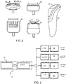
- Fig. 2 shows the main body 15 of the personal care device drive unit, together with an associated set of functional units, each of which may be releasably connected to the main body.
- the functional units comprise a rotary-type shaving unit 12, a reciprocating-type precision hair trimmer 30, a rotary-type facial brushing unit 32, and a reciprocating-type beard styler 34.
- Each has a connection interface for cooperating with the connection interface 14 of the main body.
- This is one example of a hair treatment personal care system with (at least) four different functional units. More generally, the set of different functional units may comprise at least two of the different types shown.
- the motor speed will increase until it reaches a steady state level.
- the current and accelerometer readings are not stable.
- a sufficiently stable signal can for example be obtained after a delay period, for example of between 250ms and 500ms. Therefore, the current sensor and accelerometer signals used to determine the output signal are for example obtained within a time period from 250ms to 500ms after switching on until a maximum delay for example of 1 second.
- the collection and analysis of the sensor signals takes place before the user starts using the appliance.
- the current sensor signal may be filtered in hardware and/or software.
- the average current is determined starting after the delay period and for a time window for example of up to 250ms.
- the accelerometer signal may for example be sampled for example at around 1kHz, for example at 1600Hz.
- the signals of interest are vibration signals and not accelerations caused by gravity or other slow movements of the user moving the handle, so the accelerometer signal is filtered with a Band Pass or High Pass filter, for example with a a low cut-off frequency of about 30Hz.
- the high cut-off frequency for a band pass filter may for example be around 200Hz.
- the accelerometer is for example a 3-axis device.
- the different functional units have different current and vibrational characteristics.
- Fig. 3 shows an example of the possible rotational characteristics.
- the motor 16 is shown with a 6000 rpm rotor rotation speed.
- An output gear train has a step down gear ratio of 2.273 giving a rotation speed of 2640 rpm at the output shaft of the motor.
- Each functional unit has a different gear train, giving a rotational coupling ratio.
- the shaving unit 12 has a step down ratio of 1.32 giving a 2000 rpm rotation with no (or minimal) vibration.
- the precision trimmer 30 has a ratio of 1.0 giving a 2640 rpm reciprocal motion, giving a strong vibration signal at the corresponding frequency of 44Hz.
- the rotary brush 32 has a step down ratio of 11.52 giving a 229 rpm rotation with no (or minimal) vibration.
- the beard styler unit 34 has a step down ratio of 0.437 giving a 5573 rpm reciprocal motion, giving a strong vibration signal at the corresponding frequency of 92.9Hz.
- the precision trimmer frequency may lie in the range 39.6Hz to 48.4Hz and the beard styler frequency may lie in the range 83.6Hz to 10.2Hz.
- Fig. 4 shows the frequency spectrum obtained by performing an FFT (Fast Fourier Transform) on the accelerometer x-axis signal (which is the dominant vibration axis) for a beard styler connected to the handle.
- FFT Fast Fourier Transform
- Fig. 4 shows that within the frequency window where the beard styler signal is expected, there is an amplitude peak 50. This indicates that must be a beard styler attached. However, Fig. 4 also shows an amplitude spike caused by the imbalance of the motor, at around 100Hz (corresponding to 6000 rpm). This frequency is in the same general frequency window as the beard styler signal. In some cases the amplitude of the imbalance frequency can be sufficiently high that it appears that a beard styler is attached to the handle while actually a shaving unit is attached. This would result in a misclassification.
- Peak 60 is in the precision trimmer window and peaks 62 and 64 are both in the general window where the beard styler signal is expected.
- Peak 62 is the second harmonic frequency of the precision trimmer. For example, peak 60 is at 43.5Hz and peak 62 is at 87Hz, with a lower amplitude that the first harmonic peak 60.
- the peak 64 is the motor imbalance peak. This also can result in a misclassification.
- the motor can have the speed controlled more accurately using a feedback approach.
- a digital algorithm or analogue system may be used to measure the motor speed and a digital or analogue system is used to control the motor speed accurately using feedback control.
- Fig. 6 shows an example of a possible speed feedback control system. It means that vibrations caused by the motor itself (for example from slight imbalance) will give rise to known vibration parameters, which can then be filtered or ignored as not relating to a connected functional unit. Additionally, vibrating functional units that vibrate with frequencies close to each other are also better distinguishable.
- the speed feedback control system for example controls the motor speed with a deviation of less than 1% from a target drive speed.
- a desired motor speed 70 is provided as input. It is compared with a feedback signal, and the difference is provided to a PI (proportional - integral) controller 72.
- the control output is the drive signal Um for the motor 16.
- the motor speed is detected by an encoder 74, and the encoder pulses are converted to a feedback speed signal by a pulse to speed conversion unit 76.
- the detection by the encoder may in fact be based on the motor current (i.e. the at least one current parameter).
- the motor drive current can thus be used to derive the motor speed, thereby avoiding the need for additional feedback sensors.
- the speed feedback control system avoids the need for the inherent balance of the motor to be improved by means of an expensive design. Such a design would also need to include the surrounding components such as the motor frame.
- the frequency window for the beard styler example would become 91.97Hz to 93.83 Hz. If the target speed of the motor is 6000 rpm, the imbalance frequency is at 100Hz (+/-1%). In that case the imbalance frequency falls out of the required detection window for the beard styler and misclassification can be avoided
- Fig. 7 shows the resulting components of the personal care device drive unit. Already described above are the motor 16, current sensor 18, vibration sensor 19 (i.e. accelerometer) and controller 20.
- Fig. 7 shows that the controller 20 comprises a memory 40 which stores a plurality of data sets 42. Each data set of the plurality of data sets is associated with a respective one of the set of different functional units. The controller 20 selects a data set from the plurality of data sets 42 in dependence on the measured current and vibration values and then an output signal is generated based on the selected data set.
- Fig. 7 also shows that the controller 20 includes a PI control algorithm 44. It also shows an output display 46.
- the output signal generated by the controller 20 may be used to control the motor 16 and/or to control the display 46. Both are shown in Fig. 7 . Other output devices may of course be used.
- a preferred implementation has automatic control of the identified functional unit, for example a preferred motor speed, or variation of motor speed over time.
- a functional unit it may be desired not to maintain the motor speed at 6000 rpm, but to implement a time-varying motor speed profile.
- the initial operation at 6000 rpm may be considered to be a generic operation mode which can be applied safely to any functional unit.
- the initial actuation of the motor is thus with default motor drive characteristics.
- the output signal is generated. This may for example relate to a drive scheme which is specific to the particular functional unit.
- Fig. 8 shows a series of measurements using different handles (of the same type) and using different functional units. The measurements are gathered using feedforward control. This gives about +/-10% deviation on the speed. Thus, the clustering will be even better when the feedback speed control is used.
- Max1 is the maximum amplitude found in the frequency window where the precision trimmer (PT) and nose trimmer (NT) is expected.
- Max2 is the maximum amplitude found in the frequency window where the beard styler (BS) is expected.
- Region 80 relates to the shaving brush (BR)
- region 82 relates to a nose trimmer (NT)
- region 84 relates to the precision trimmer (PT)
- region 86 relates to the shaving unit
- region 88 relates to the beard styler (BS).
- the set of functional units comprises a brush, precision trimmer, shaving unit and beard styler.
- the set of different functional units comprises a first (precision trimmer) and a second (beard styler) functional unit, each comprising a functional component (e.g. blade) configured to perform a reciprocating motion, and at least a third (shaving unit) and a fourth (brush) functional unit, each comprising a functional component (e.g. cutter disk or bristle head) configured to perform a rotating motion in a single direction.
- the first and the second functional units are then associated with the occurrence in the main body of a maximum vibration amplitude above, respectively, a first and a second predefined threshold value in, respectively, mutually different first and second predefined ranges of vibration frequencies. Thus, they vibrate at different frequencies with their own characteristic amplitude.
- the third and fourth functional units are associated with the occurrence of a value of the at least one current parameter in, respectively, mutually different first and second predefined ranges of the at least one current parameter. Thus, they result in characteristic load current for the driving motor.
- the controller determines whether a maximum vibration amplitude occurring within a predefined range of vibration frequencies is above a predefined threshold value.
- the controller may seek to identify a vibration with a characteristic amplitude within a certain frequency band.
- the controller generates, in a first step, an output signal associated with the first or the second functional unit when a maximum vibration amplitude occurring within, respectively, the first or the second predefined range of vibration frequencies is above, respectively, the first or the second predefined threshold value.
- the functional unit must be a precision trimmer. If this was in the frequency window where the beard styler is expected, the functional unit must be a beard styler.
- a brush or a shaving unit must be attached. In that case those two can be distinguished by looking at the average current level. Below a certain current threshold it must be the brush, above this threshold it must be the shaving unit.
- the controller thus generates, in a second step following the first step, a control signal associated with the third or the fourth functional unit when the value of the at least one current parameter is in, respectively, said first or said second predefined range of the at least one current parameter.
- a simply switch may be used to detect whether or not any functional unit is attached.
- Fig. 9 shows this two-step approach graphically.
- the first step is shown as 90.
- the vibration amplitude is measured in the two frequency windows, as shown in the graph.
- the first measurement identifies whether or not a precision trimmer (PT) is present, and the second measurement identifies whether or not a beard styler (BS) is present.
- PT precision trimmer
- BS beard styler
- the second step is shown as step 92.
- the average current is used to distinguish between the brush (BR) and shaving unit (SU) (and optionally also a nose trimmer NT, as shown, in the case that frequency determination alone is not sufficient).
- the invention may be applied to personal care systems other than shaving systems.
- shaving systems For example it may be applied to other hair care systems such as epilator systems, or even to oral healthcare modular systems.
- a computer program may be stored/distributed on a suitable medium, such as an optical storage medium or a solid-state medium supplied together with or as part of other hardware, but may also be distributed in other forms, such as via the Internet or other wired or wireless telecommunication systems. If the term “adapted to” is used in the claims or description, it is noted the term “adapted to” is intended to be equivalent to the term “configured to”.
Landscapes
- Life Sciences & Earth Sciences (AREA)
- Forests & Forestry (AREA)
- Engineering & Computer Science (AREA)
- Mechanical Engineering (AREA)
- Brushes (AREA)
- Dry Shavers And Clippers (AREA)
- Percussion Or Vibration Massage (AREA)
- Control Of Electric Motors In General (AREA)
- Control Of Direct Current Motors (AREA)
Priority Applications (9)
| Application Number | Priority Date | Filing Date | Title |
|---|---|---|---|
| EP19192763.1A EP3782509A1 (fr) | 2019-08-21 | 2019-08-21 | Système de soins personnels avec un ensemble d'unités fonctionnelles |
| JP2022511067A JP7147102B2 (ja) | 2019-08-21 | 2020-08-14 | 機能ユニットのセットを備えたパーソナルヘルスケアシステム |
| CN202080006450.5A CN113165195A (zh) | 2019-08-21 | 2020-08-14 | 具有一组功能单元的个人护理系统 |
| ES20754261T ES2935268T3 (es) | 2019-08-21 | 2020-08-14 | Sistema de cuidado personal con un conjunto de unidades funcionales |
| PCT/EP2020/072824 WO2021032604A1 (fr) | 2019-08-21 | 2020-08-14 | Système de soins corporels ayant un ensemble d'unités fonctionnelles |
| US17/299,095 US20220184831A1 (en) | 2019-08-21 | 2020-08-14 | Personal care system with a set of functional units |
| KR1020217015673A KR20220051300A (ko) | 2019-08-21 | 2020-08-14 | 한 세트의 기능성 유닛을 갖는 개인 케어 시스템 |
| EP20754261.4A EP3855976B1 (fr) | 2019-08-21 | 2020-08-14 | Système de soins corporels ayant un ensemble d'unités fonctionnelles |
| SG11202104565VA SG11202104565VA (en) | 2019-08-21 | 2020-08-14 | Personal care system with a set of functional units |
Applications Claiming Priority (1)
| Application Number | Priority Date | Filing Date | Title |
|---|---|---|---|
| EP19192763.1A EP3782509A1 (fr) | 2019-08-21 | 2019-08-21 | Système de soins personnels avec un ensemble d'unités fonctionnelles |
Publications (1)
| Publication Number | Publication Date |
|---|---|
| EP3782509A1 true EP3782509A1 (fr) | 2021-02-24 |
Family
ID=67659631
Family Applications (2)
| Application Number | Title | Priority Date | Filing Date |
|---|---|---|---|
| EP19192763.1A Withdrawn EP3782509A1 (fr) | 2019-08-21 | 2019-08-21 | Système de soins personnels avec un ensemble d'unités fonctionnelles |
| EP20754261.4A Active EP3855976B1 (fr) | 2019-08-21 | 2020-08-14 | Système de soins corporels ayant un ensemble d'unités fonctionnelles |
Family Applications After (1)
| Application Number | Title | Priority Date | Filing Date |
|---|---|---|---|
| EP20754261.4A Active EP3855976B1 (fr) | 2019-08-21 | 2020-08-14 | Système de soins corporels ayant un ensemble d'unités fonctionnelles |
Country Status (8)
| Country | Link |
|---|---|
| US (1) | US20220184831A1 (fr) |
| EP (2) | EP3782509A1 (fr) |
| JP (1) | JP7147102B2 (fr) |
| KR (1) | KR20220051300A (fr) |
| CN (1) | CN113165195A (fr) |
| ES (1) | ES2935268T3 (fr) |
| SG (1) | SG11202104565VA (fr) |
| WO (1) | WO2021032604A1 (fr) |
Cited By (1)
| Publication number | Priority date | Publication date | Assignee | Title |
|---|---|---|---|---|
| US11259626B2 (en) * | 2017-04-17 | 2022-03-01 | Koninklijke Philips N.V. | Personal care device |
Families Citing this family (1)
| Publication number | Priority date | Publication date | Assignee | Title |
|---|---|---|---|---|
| JP7457482B2 (ja) | 2019-10-24 | 2024-03-28 | マクセルイズミ株式会社 | ロータリー式電気かみそり |
Citations (2)
| Publication number | Priority date | Publication date | Assignee | Title |
|---|---|---|---|---|
| WO2014135589A1 (fr) * | 2013-03-07 | 2014-09-12 | I-Dent Innovations For Dentistry Sa | Appareil dentaire pour traitement dentaire dans une bouche |
| WO2018192788A1 (fr) | 2017-04-17 | 2018-10-25 | Koninklijke Philips N.V. | Dispositif de soins personnels |
Family Cites Families (16)
| Publication number | Priority date | Publication date | Assignee | Title |
|---|---|---|---|---|
| JP3714130B2 (ja) | 2000-07-18 | 2005-11-09 | 松下電工株式会社 | トリマーヘッドとシェーバーヘッドを選択して交換可能な電気バリカン |
| DE10052296C1 (de) * | 2000-10-20 | 2002-04-04 | Braun Gmbh | Elektrisch betriebenes Haarentfernungsgerät mit einer Beleuchtungseinrichtung |
| US8141253B2 (en) * | 2007-08-31 | 2012-03-27 | The Gillette Company | Personal care assembly |
| DE102008005549B4 (de) * | 2008-01-23 | 2015-04-30 | Braun Gmbh | Rasiergerät mit einer Regelung des Untermessers und Verfahren zur Regelung des Untermessers eines Rasiergeräts |
| JP5842158B2 (ja) * | 2011-02-28 | 2016-01-13 | パナソニックIpマネジメント株式会社 | 電気かみそり |
| RU2662736C2 (ru) * | 2014-06-12 | 2018-07-30 | Конинклейке Филипс Н.В. | Система сигнализации |
| KR101962678B1 (ko) * | 2016-05-27 | 2019-03-27 | 박승규 | 다기능 면도기 |
| RU2732394C9 (ru) * | 2016-12-01 | 2021-05-05 | Конинклейке Филипс Н.В. | Устройство для срезания волос, содержащее световой индикатор |
| US20190224870A1 (en) * | 2018-01-19 | 2019-07-25 | The Gillette Company Llc | Shaving appliance including a notification cirucit for communicating shave stroke direction information |
| US10589437B2 (en) * | 2018-01-19 | 2020-03-17 | The Gillette Company Llc | Personal appliance |
| US20190224869A1 (en) * | 2018-01-19 | 2019-07-25 | The Gillette Company Llc | Shaving appliance including a notification circuit for communicating cumulative shave event information |
| GB201808555D0 (en) * | 2018-05-24 | 2018-07-11 | Playbrush Ltd | Electric toothbrush system |
| CN108772855A (zh) * | 2018-05-25 | 2018-11-09 | 吴让攀 | 一种振动剃刀 |
| EP3725473A1 (fr) * | 2019-04-18 | 2020-10-21 | Koninklijke Philips N.V. | Rasoir électrique à détection de pression |
| EP3769644A1 (fr) * | 2019-07-25 | 2021-01-27 | Koninklijke Philips N.V. | Dispositif de traitement de la peau et procédé de commande d'un dispositif de traitement de la peau |
| GB201912787D0 (en) * | 2019-09-05 | 2019-10-23 | Playbrush Ltd | Electric toothbrush system with pressure detection |
-
2019
- 2019-08-21 EP EP19192763.1A patent/EP3782509A1/fr not_active Withdrawn
-
2020
- 2020-08-14 ES ES20754261T patent/ES2935268T3/es active Active
- 2020-08-14 US US17/299,095 patent/US20220184831A1/en active Pending
- 2020-08-14 WO PCT/EP2020/072824 patent/WO2021032604A1/fr unknown
- 2020-08-14 CN CN202080006450.5A patent/CN113165195A/zh active Pending
- 2020-08-14 JP JP2022511067A patent/JP7147102B2/ja active Active
- 2020-08-14 SG SG11202104565VA patent/SG11202104565VA/en unknown
- 2020-08-14 KR KR1020217015673A patent/KR20220051300A/ko unknown
- 2020-08-14 EP EP20754261.4A patent/EP3855976B1/fr active Active
Patent Citations (2)
| Publication number | Priority date | Publication date | Assignee | Title |
|---|---|---|---|---|
| WO2014135589A1 (fr) * | 2013-03-07 | 2014-09-12 | I-Dent Innovations For Dentistry Sa | Appareil dentaire pour traitement dentaire dans une bouche |
| WO2018192788A1 (fr) | 2017-04-17 | 2018-10-25 | Koninklijke Philips N.V. | Dispositif de soins personnels |
Cited By (1)
| Publication number | Priority date | Publication date | Assignee | Title |
|---|---|---|---|---|
| US11259626B2 (en) * | 2017-04-17 | 2022-03-01 | Koninklijke Philips N.V. | Personal care device |
Also Published As
| Publication number | Publication date |
|---|---|
| EP3855976A1 (fr) | 2021-08-04 |
| SG11202104565VA (en) | 2021-05-28 |
| JP7147102B2 (ja) | 2022-10-04 |
| WO2021032604A1 (fr) | 2021-02-25 |
| ES2935268T3 (es) | 2023-03-03 |
| JP2022539430A (ja) | 2022-09-08 |
| KR20220051300A (ko) | 2022-04-26 |
| US20220184831A1 (en) | 2022-06-16 |
| CN113165195A (zh) | 2021-07-23 |
| EP3855976B1 (fr) | 2022-10-19 |
Similar Documents
| Publication | Publication Date | Title |
|---|---|---|
| EP3855976B1 (fr) | Système de soins corporels ayant un ensemble d'unités fonctionnelles | |
| CN107072761B (zh) | 标识个人护理器具的附件和方法 | |
| US10779924B2 (en) | Electric toothbrush device and method | |
| CN101969879B (zh) | 电动牙刷 | |
| JP7296991B2 (ja) | 電動歯ブラシシステム | |
| EP2088959B1 (fr) | Système pour adapter le fonctionnement résonant d'un appareil de soins personnels pendant la durée de vie de celui-ci | |
| CN108852546A (zh) | 一种基于压力检测控制刷牙强度的方法及电动牙刷 | |
| EP3391793A1 (fr) | Dispositif de soins personnels | |
| CN106103018A (zh) | 电动剃须刀 | |
| JP6946330B2 (ja) | 口腔洗浄デバイスを較正する方法及びシステム | |
| AU2017276751A1 (en) | Food processor comprising at least one processor device and one monitoring device | |
| JP2019202149A (ja) | 口腔クリーニング装置においてセンサのドライブトレーン干渉を最小にするための方法及びシステム | |
| EP3548231B1 (fr) | Appareil de coupe de cheveux comprenant un détecteur de courant | |
| RU2784550C2 (ru) | Приводной блок устройства для личной гигиены, система для личной гигиены, способ управления функциональным блоком и компьютерочитаемый носитель | |
| JP6599656B2 (ja) | 電動歯ブラシ及びブラッシング部位推定方法 | |
| EP4344837A1 (fr) | Système et dispositif de soins personnels | |
| EP4337434A1 (fr) | Tondeuses à cheveux | |
| CN116601853A (zh) | 编码器、电机、电机驱动器和主计算机 | |
| CN117814942A (zh) | 电动牙刷的电子限位控制方法、装置及电动牙刷 | |
| RU2021112758A (ru) | Система для личной гигиены с набором функциональных блоков | |
| CN111769687A (zh) | 主动减震装置及控制方法 | |
| CN116539142A (zh) | 马达振动检测方法、马达振动控制方法、马达及电动牙刷 |
Legal Events
| Date | Code | Title | Description |
|---|---|---|---|
| PUAI | Public reference made under article 153(3) epc to a published international application that has entered the european phase |
Free format text: ORIGINAL CODE: 0009012 |
|
| STAA | Information on the status of an ep patent application or granted ep patent |
Free format text: STATUS: THE APPLICATION HAS BEEN PUBLISHED |
|
| AK | Designated contracting states |
Kind code of ref document: A1 Designated state(s): AL AT BE BG CH CY CZ DE DK EE ES FI FR GB GR HR HU IE IS IT LI LT LU LV MC MK MT NL NO PL PT RO RS SE SI SK SM TR |
|
| AX | Request for extension of the european patent |
Extension state: BA ME |
|
| STAA | Information on the status of an ep patent application or granted ep patent |
Free format text: STATUS: THE APPLICATION IS DEEMED TO BE WITHDRAWN |
|
| 18D | Application deemed to be withdrawn |
Effective date: 20210825 |