EP3779508B1 - Re-directing radar transmission power for interference mitigation - Google Patents
Re-directing radar transmission power for interference mitigation Download PDFInfo
- Publication number
- EP3779508B1 EP3779508B1 EP19211579.8A EP19211579A EP3779508B1 EP 3779508 B1 EP3779508 B1 EP 3779508B1 EP 19211579 A EP19211579 A EP 19211579A EP 3779508 B1 EP3779508 B1 EP 3779508B1
- Authority
- EP
- European Patent Office
- Prior art keywords
- radar
- radar signal
- interference
- frequency
- transmission power
- Prior art date
- Legal status (The legal status is an assumption and is not a legal conclusion. Google has not performed a legal analysis and makes no representation as to the accuracy of the status listed.)
- Active
Links
- 230000005540 biological transmission Effects 0.000 title description 35
- 230000000116 mitigating effect Effects 0.000 title description 5
- 238000000034 method Methods 0.000 claims description 53
- 230000008054 signal transmission Effects 0.000 claims description 50
- 230000002452 interceptive effect Effects 0.000 claims description 49
- 238000012544 monitoring process Methods 0.000 claims description 28
- 238000001914 filtration Methods 0.000 claims description 8
- 230000001131 transforming effect Effects 0.000 claims description 8
- 230000004044 response Effects 0.000 claims description 5
- 238000012545 processing Methods 0.000 description 23
- 238000001514 detection method Methods 0.000 description 10
- 230000002441 reversible effect Effects 0.000 description 10
- 230000008439 repair process Effects 0.000 description 9
- 230000000694 effects Effects 0.000 description 7
- 230000001629 suppression Effects 0.000 description 7
- 230000008901 benefit Effects 0.000 description 6
- 238000004891 communication Methods 0.000 description 6
- 230000008859 change Effects 0.000 description 5
- 238000006243 chemical reaction Methods 0.000 description 3
- 238000004590 computer program Methods 0.000 description 3
- 230000009471 action Effects 0.000 description 2
- 230000003044 adaptive effect Effects 0.000 description 2
- 238000013459 approach Methods 0.000 description 2
- 230000006870 function Effects 0.000 description 2
- 238000013461 design Methods 0.000 description 1
- 230000001627 detrimental effect Effects 0.000 description 1
- 238000005562 fading Methods 0.000 description 1
- 230000007274 generation of a signal involved in cell-cell signaling Effects 0.000 description 1
- 230000007246 mechanism Effects 0.000 description 1
- 230000003287 optical effect Effects 0.000 description 1
- 230000002085 persistent effect Effects 0.000 description 1
- 238000012805 post-processing Methods 0.000 description 1
- 230000000717 retained effect Effects 0.000 description 1
- 238000005070 sampling Methods 0.000 description 1
- 239000007787 solid Substances 0.000 description 1
- 238000001228 spectrum Methods 0.000 description 1
Images


Classifications
-
- G—PHYSICS
- G01—MEASURING; TESTING
- G01S—RADIO DIRECTION-FINDING; RADIO NAVIGATION; DETERMINING DISTANCE OR VELOCITY BY USE OF RADIO WAVES; LOCATING OR PRESENCE-DETECTING BY USE OF THE REFLECTION OR RERADIATION OF RADIO WAVES; ANALOGOUS ARRANGEMENTS USING OTHER WAVES
- G01S7/00—Details of systems according to groups G01S13/00, G01S15/00, G01S17/00
- G01S7/02—Details of systems according to groups G01S13/00, G01S15/00, G01S17/00 of systems according to group G01S13/00
- G01S7/023—Interference mitigation, e.g. reducing or avoiding non-intentional interference with other HF-transmitters, base station transmitters for mobile communication or other radar systems, e.g. using electro-magnetic interference [EMI] reduction techniques
-
- G—PHYSICS
- G01—MEASURING; TESTING
- G01S—RADIO DIRECTION-FINDING; RADIO NAVIGATION; DETERMINING DISTANCE OR VELOCITY BY USE OF RADIO WAVES; LOCATING OR PRESENCE-DETECTING BY USE OF THE REFLECTION OR RERADIATION OF RADIO WAVES; ANALOGOUS ARRANGEMENTS USING OTHER WAVES
- G01S13/00—Systems using the reflection or reradiation of radio waves, e.g. radar systems; Analogous systems using reflection or reradiation of waves whose nature or wavelength is irrelevant or unspecified
- G01S13/02—Systems using reflection of radio waves, e.g. primary radar systems; Analogous systems
- G01S13/06—Systems determining position data of a target
- G01S13/08—Systems for measuring distance only
- G01S13/32—Systems for measuring distance only using transmission of continuous waves, whether amplitude-, frequency-, or phase-modulated, or unmodulated
- G01S13/34—Systems for measuring distance only using transmission of continuous waves, whether amplitude-, frequency-, or phase-modulated, or unmodulated using transmission of continuous, frequency-modulated waves while heterodyning the received signal, or a signal derived therefrom, with a locally-generated signal related to the contemporaneously transmitted signal
- G01S13/343—Systems for measuring distance only using transmission of continuous waves, whether amplitude-, frequency-, or phase-modulated, or unmodulated using transmission of continuous, frequency-modulated waves while heterodyning the received signal, or a signal derived therefrom, with a locally-generated signal related to the contemporaneously transmitted signal using sawtooth modulation
-
- G—PHYSICS
- G01—MEASURING; TESTING
- G01S—RADIO DIRECTION-FINDING; RADIO NAVIGATION; DETERMINING DISTANCE OR VELOCITY BY USE OF RADIO WAVES; LOCATING OR PRESENCE-DETECTING BY USE OF THE REFLECTION OR RERADIATION OF RADIO WAVES; ANALOGOUS ARRANGEMENTS USING OTHER WAVES
- G01S13/00—Systems using the reflection or reradiation of radio waves, e.g. radar systems; Analogous systems using reflection or reradiation of waves whose nature or wavelength is irrelevant or unspecified
- G01S13/02—Systems using reflection of radio waves, e.g. primary radar systems; Analogous systems
- G01S13/06—Systems determining position data of a target
- G01S13/42—Simultaneous measurement of distance and other co-ordinates
-
- G—PHYSICS
- G01—MEASURING; TESTING
- G01S—RADIO DIRECTION-FINDING; RADIO NAVIGATION; DETERMINING DISTANCE OR VELOCITY BY USE OF RADIO WAVES; LOCATING OR PRESENCE-DETECTING BY USE OF THE REFLECTION OR RERADIATION OF RADIO WAVES; ANALOGOUS ARRANGEMENTS USING OTHER WAVES
- G01S13/00—Systems using the reflection or reradiation of radio waves, e.g. radar systems; Analogous systems using reflection or reradiation of waves whose nature or wavelength is irrelevant or unspecified
- G01S13/88—Radar or analogous systems specially adapted for specific applications
- G01S13/93—Radar or analogous systems specially adapted for specific applications for anti-collision purposes
- G01S13/931—Radar or analogous systems specially adapted for specific applications for anti-collision purposes of land vehicles
-
- G—PHYSICS
- G01—MEASURING; TESTING
- G01S—RADIO DIRECTION-FINDING; RADIO NAVIGATION; DETERMINING DISTANCE OR VELOCITY BY USE OF RADIO WAVES; LOCATING OR PRESENCE-DETECTING BY USE OF THE REFLECTION OR RERADIATION OF RADIO WAVES; ANALOGOUS ARRANGEMENTS USING OTHER WAVES
- G01S7/00—Details of systems according to groups G01S13/00, G01S15/00, G01S17/00
- G01S7/02—Details of systems according to groups G01S13/00, G01S15/00, G01S17/00 of systems according to group G01S13/00
- G01S7/023—Interference mitigation, e.g. reducing or avoiding non-intentional interference with other HF-transmitters, base station transmitters for mobile communication or other radar systems, e.g. using electro-magnetic interference [EMI] reduction techniques
- G01S7/0233—Avoidance by phase multiplex
-
- G—PHYSICS
- G01—MEASURING; TESTING
- G01S—RADIO DIRECTION-FINDING; RADIO NAVIGATION; DETERMINING DISTANCE OR VELOCITY BY USE OF RADIO WAVES; LOCATING OR PRESENCE-DETECTING BY USE OF THE REFLECTION OR RERADIATION OF RADIO WAVES; ANALOGOUS ARRANGEMENTS USING OTHER WAVES
- G01S7/00—Details of systems according to groups G01S13/00, G01S15/00, G01S17/00
- G01S7/02—Details of systems according to groups G01S13/00, G01S15/00, G01S17/00 of systems according to group G01S13/00
- G01S7/023—Interference mitigation, e.g. reducing or avoiding non-intentional interference with other HF-transmitters, base station transmitters for mobile communication or other radar systems, e.g. using electro-magnetic interference [EMI] reduction techniques
- G01S7/0235—Avoidance by time multiplex
-
- G—PHYSICS
- G01—MEASURING; TESTING
- G01S—RADIO DIRECTION-FINDING; RADIO NAVIGATION; DETERMINING DISTANCE OR VELOCITY BY USE OF RADIO WAVES; LOCATING OR PRESENCE-DETECTING BY USE OF THE REFLECTION OR RERADIATION OF RADIO WAVES; ANALOGOUS ARRANGEMENTS USING OTHER WAVES
- G01S7/00—Details of systems according to groups G01S13/00, G01S15/00, G01S17/00
- G01S7/02—Details of systems according to groups G01S13/00, G01S15/00, G01S17/00 of systems according to group G01S13/00
- G01S7/023—Interference mitigation, e.g. reducing or avoiding non-intentional interference with other HF-transmitters, base station transmitters for mobile communication or other radar systems, e.g. using electro-magnetic interference [EMI] reduction techniques
- G01S7/0236—Avoidance by space multiplex
-
- G—PHYSICS
- G01—MEASURING; TESTING
- G01S—RADIO DIRECTION-FINDING; RADIO NAVIGATION; DETERMINING DISTANCE OR VELOCITY BY USE OF RADIO WAVES; LOCATING OR PRESENCE-DETECTING BY USE OF THE REFLECTION OR RERADIATION OF RADIO WAVES; ANALOGOUS ARRANGEMENTS USING OTHER WAVES
- G01S7/00—Details of systems according to groups G01S13/00, G01S15/00, G01S17/00
- G01S7/02—Details of systems according to groups G01S13/00, G01S15/00, G01S17/00 of systems according to group G01S13/00
- G01S7/35—Details of non-pulse systems
Definitions
- the present disclosure relates to interference in radar signals, and in particular to suppression of such interference.
- the radar systems discussed herein are suitable as vehicle radar systems.
- radar transceivers that are arranged for generating radar signals that are transmitted, reflected and received by means of appropriate antennas comprised in the radar system.
- the radar signals may for example be in the form of FMCW (Frequency Modulated Continuous Wave) signals where frequency chirp signals are formed in a well-known manner.
- FMCW Frequency Modulated Continuous Wave
- radars may interfere with each other as frequency chirps cross or come close to each other in frequency. When this happens, a burst of interference somewhere within the received signal during one or more of the chirp signals can be observed.
- FFT Fast Fourier Transform
- the noise floor will be raised since the noise may be spread across a wide band of frequencies. This raising of the noise floor has the effect of reducing the range and accuracy of the radar, which of course is undesirable.
- EP3489710 A1 discloses an arrangement for radar interference suppression.
- interference mitigation is achieved by replacing obtained radar samples by modified samples which are generated based on frequency domain processing of batches of samples.
- US 2007/188373 describes an automotive radar system which comprises an interference detection device.
- This interference detection device detects the presence of an interfering signal, whereupon a control device modifies one or more properties of the transmitted signal, such as its center frequency of bandwidth.
- US 2019/056476 discloses a radar unit that is configured to operate a time-discontinuous mode of operation that includes a first time portion used as an interference monitoring period and a second time portion used by the radar unit in the normal data acquisition mode of operation, where interference signals are detected during the monitoring period.
- US 2010/019950 discloses a radar system where a sampled beat signal is split into a plurality of short-time data and an interference component frequency is detected from a frequency spectrum of the short-time data. An absolute value of an incoming direction of interference components is estimated and is used when operating a filter for suppressing the interference components.
- US 2018/031674 relates to a phase modulated continuous wave (PMCW) radar system which comprises a form of in-band interference sensing mechanism, where the transmitter is briefly turned off in order to detect interference from nearby radar transceivers.
- PMCW phase modulated continuous wave
- WO 2019/106656 discloses a radar system based on time and frequency hopping, with a TX/RX control circuit that incorporates mutual interference detection.
- the method comprises transmitting a radar signal at a frequency F(t), receiving a radar signal, monitoring frequencies adjacent to the frequency F(t) for interference, and, if interference is detected (S4) in the adjacent frequencies and re-directing radar signal transmission power for a cross-over time duration.
- the cross-over time duration may be estimated by observing the aggressor signal prior to it appearing within the IF bandwidth or determined by monitoring it as it traverses across the IF bandwidth.
- the radar signal is a frequency modulated continuous wave (FMCW) radar signal having the frequency F(t). Determining the cross-over time duration comprises determining a relative frequency gradient between the transmitted radar signal and an interfering radar signal.
- FMCW frequency modulated continuous wave
- the method can be used both to mitigate interference from legacy radar transmitters, and also to mitigate interference experienced by legacy radar transceivers.
- the proposed method is of relatively low complexity and requires no explicit communication between radar transceivers in order to synchronize radar transmission, which is an advantage.
- determining the cross-over time duration may also comprise tracking the interference as it crosses a receive bandwidth, or IF bandwidth, of the radar transceiver.
- the interference can be followed as it traverses the receive frequency band.
- the radar transceiver can determine when the interference is no longer present, i.e., having exited the IF bandwidth, whereby radar transmission can be resumed. Consequently, determining the cross-over time duration can be performed implicitly simply by detecting onset and cessation of the interference.
- the monitoring comprises filtering the received radar signal to detect signal content at the adjacent frequencies.
- Filtering is an efficient and robust method for detecting signal content at the adjacent frequencies.
- a filter bank By using a filter bank, a frequency slope parameter of the interfering radar transmission can be robustly estimated, which is an advantage.
- the monitoring comprises wavelet transforming or Fourier transforming the received radar signal to detect signal content at the adjacent frequencies.
- Fourier transforming and/or Wavelet transforming provides a more accurate means for detecting and characterizing interference as it traverses over frequency. For instance, a relative or absolute frequency slope parameter of the interfering radar signal can be determined, from which the cross-over time duration can be estimated.
- the monitoring comprises storing previously received radar signal segments.
- previously received radar signal samples it becomes possible to track and characterize one or more interfering radar signals as they cross different section of the transmitted radar signals.
- the interference time instants will change from sweep to sweep, allowing the radar transceiver to characterize the interfering radar waveform in terms of at least relative frequency slope.
- determining the cross-over time duration may also comprise applying a contention-based back-off routine. If both victim and aggressor have the proposed system fitted, it would be sub-optimal if both radars switched off simultaneously. A random time back-off before switching off transmission may cover this eventuality, as well as random switch-back-on in case it is detected that the other transceiver also switched off - like a kind of mini contention resolution.
- determining the cross-over time duration may also comprise re-configuring a frequency derivative of the transmitted radar signal in dependence of parameters of the detected interference. By flipping the direction of the frequency sweep, the time duration of the cross-over event can be significantly shortened in some cases, which is an advantage. According to aspects, determining the cross-over time duration comprises determining a fixed cross-over time duration. Using a fixed cross-over time duration represents a low complexity option, which reduces computational burden on the overall system.
- re-directing the radar signal transmission power comprises predicting and repairing the received radar signal.
- repairing the received signal i.e., patching up the missing part, impact to further processing steps is reduced.
- re-directing radar signal transmission power comprises at least one of
- radar signal transmission power can be re-directed in a safe and quick manner, very precisely causing a desired re-direction of radar signal transmission power that easily can be re-stored when suitable. No particular start-up or closing-down times are necessary.
- radar transceivers and vehicles associated with the above-mentioned advantages.
- the herein disclosed methods may be executed in a vehicle or at least in part by a remote server wirelessly connected to the vehicle.
- FIG. 1 shows a vehicle 100 equipped with a vehicle radar system 110, 130.
- the vehicle radar system comprises at least one vehicle radar transceiver 110 and a radar data processing system or control unit 130. It is appreciated that the radar transceiver 110 and the control unit 130 may be comprised in a single physical unit or may be distributed over more than one physical unit. Some parts of the functionality may even be comprised in a remote server 160 connected to the vehicle via wireless link 150.
- the vehicle radar system 110, 130 comprises a transceiver arrangement that is arranged for generating and transmitting radar signals in the form of frequency modulated continuous wave (FMCW) signals, sometimes also referred to as radar chirp signals, and to receive reflected radar signals 125, where the transmitted signals have been reflected by an object 140.
- FMCW frequency modulated continuous wave
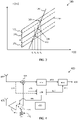
- a transmitted FMCW signal is in the form of a continuous wave where the output frequency F(t) varies from a first frequency f start to a second frequency f stop over the course of a ramp r.
- Most FMCW transmissions comprise repeating cycles of a plurality of frequency ramps r as shown in Figure 2 , however, some radar transmissions only comprise one slow chirp, i.e., different from the example transmission of Figure 2 .
- a cycle for such a chirp signal lasts for a certain cycle time t c , each ramp r lasts a certain ramp time t r , having a ramp period time t T . Between two consecutive ramps of the chirp signal there is often inserted a delay time t D .
- FMCW radar operation and signal processing is known in general and will not be discussed in more detail herein.
- the radar data processing system 130 is arranged to control operation of the radar transceiver 110, and to obtain data from the radar transceiver 110, such as detections or data points corresponding to objects 140 in vicinity of the vehicle 100.
- the radar transceiver 110 may comprise a single radar unit or a plurality of radar units, potentially of different type and/or of different configuration.
- the different radar units may, e.g., be arranged as front radars, side radars, and/or rearward facing radars.
- the radar transceiver 110 is associated with a field of view 120.
- a boresight direction 121 of the radar 110 often coincides with a center line of the field of view 120.
- the boresight direction may point in some other angle compared to the forward direction of the vehicle 100.
- the vehicle radar system 110, 130 in Figure 1 is subject to interference 180 from an external radar transceiver.
- Such interference can come from a plurality of different sources, including other radar transceivers on the same vehicle 100.
- interference occurs when two or more radar signals 180, 210 are close together in frequency for a period of time, specifically within the intermediate frequency (IF) receiving bandwidth of each other or cross each other in frequency.
- IF intermediate frequency
- the net effect is that the time domain signal, i.e., the raw data or digitally sampled signal obtained after frequency down-conversion of the received radio frequency signal, experiences a burst of interference, which may be high compared to the wanted radar-return signal. There may be multiple interference bursts within a short time window.
- interference is here to be interpreted broadly to comprise any signal component or signal comprised in the radar signal which has a detrimental effect on performance of a system making use of the received radar signal. Consequently, interference may comprise any of, e.g., external interference from other transmitters and radio frequency sources, internal interference from circuitry of the radar transceiver or other active components located close to the radar receiver, and pulsed interference signals which are associated with limited time duration. Nevertheless, the techniques disclosed herein are particularly suitable for mitigating interference caused by an interfering FMCW transceiver.
- the vehicle radar system 110,130 may be connected via wireless link 150 to a remote server 160, which in turn may be comprised in a remote network 170.
- This server and network may be configured to assist the vehicle 100 in performing radar interference suppression.
- the remote server 160 may be arranged to configure parameters such as detection thresholds used by the control unit 130 and the like remotely, and also transmission parameters of the radar transceiver, such as frequency slopes and the like.
- An optional storage module may also be comprised in the vehicle radar system.
- the storage module may store data comprising information about a surrounding environment of the vehicle 100 and about past vehicle operations, such as past experiences of radar interference and radar interference suppression operations.
- the storage module will be discussed in more detail below in connection to Figure 10 .
- FIG 3 illustrates two FMCW radar signals 210, 180, where the radar signal 210 may be a chirp from the sequence of chirps 200 illustrated in Figure 2 .
- the radar signal 210 may correspond to a radar signal transmitted by the vehicle 100, while radar signal 180 is an interfering radar signal.
- the two radar signals have different frequency slopes, i.e., the frequency change with respect to time is different for the two signals.
- the two radar signals therefore cross each other at a crossing 330 at time t 3 , whereupon interference occurs (to both signals).
- a radar transceiver such as the radar transceiver 110 is often associated with a receiving bandwidth in which signals are received, sometimes referred to as the intermediate frequency (IF) bandwidth of the radar transceiver. Radio frequency signals received outside of this bandwidth are filtered out by the receiver.
- IF intermediate frequency
- the frequency location of the IF band moves linearly over time together with the transmitted center frequency.
- the IF bandwidth 370 of the radar transceiver 110 is indicated in Figure 3 . It is appreciated that the figure illustrates the case for a single channel mixer (only the I-channel or "real"). In the case of a quadrature down-conversion comprising I and Q outputs, it is understood that the upper and lower sidebands could be available separately at the processor as explained in US2019011533 , but the general concept illustrated here would of course still be valid.
- the interfering radar signal 180 enters the IF bandwidth of the radar signal 210 at time t 2 , and therefore starts to interfere with the radar signal 210. This interference continues past the point in time t 3 when the crossing 330 occurs until the interfering radar signal leaves the IF bandwidth of the radar signal 210 at an exit point 360, which occurs at time t 4 . Consequently, the radar signal 210 suffers from interference at least during a cross-over time duration from an entry point 350 at time t 2 to the exit point 360 at time t 4 .
- the time it takes for the interfering radar signal 180 to cross the IF bandwidth of the transmitted radar signal 210 is obtained as the IF bandwidth (in Hz) divided by the relative frequency slope of the two waveforms (in Hz/sec).
- the radar transceiver 110 may re-direct its radar signal transmission power during the cross-over time duration for the interference for example by re-directing radar signal transmission power towards a resistive termination before reaching a transmit antenna 476 as shown in Figure 4 and Figure 5 , or by steering radar signal transmission power in another angular direction as shown in Figure 6 . These examples will be described more in detail later.
- the receive chain of the radar transceiver 110 may either be turned off completely so that nothing is received (including both desired and interfering signal) or be left on in order to monitor or track the interfering signal as it traverses the receive band. In case the receiver is left on, the data would of course not be retained for further processing, but discarded, since there is no useful transmission from the system at this time. Also, by re-directing radar transmission power, no interference is generated at the other radar transceiver, thus sparing also the interfering radar transceiver. It is an advantage that the proposed method not only spares the radar transceiver 110 from interference, but also the interfering radar transceiver.
- the techniques disclosed herein also comprises determining a severity level of the interference, and only re-directing transmission power if the interference meets some severity criteria. For instance, a threshold on interference power can be set, and only such interference associated with a power above the threshold would then trigger re-directing of transmission power.
- the threshold can be fixed or adapted during radar operation. For instance, the threshold can start out relatively low in a sequence of chirps and increase each time transmission power is re-directed. This way it can be ensured that the transmitted signal transmission power is not re-directed too often.
- the threshold can be set in dependence of the traffic scenario, and/or in dependence of the interference scenario.
- the disclosed technique comprises discontinuous radar transmission in the sense that the transmission power may be re-directed from time to time as interfering radar signals traverse the IF bandwidth of the radar transceiver 110.
- Figure 3 exemplifies this interference mitigation technique; the interfering radar signal 180 is detected between time t 1 and time t 2 as it enters a frequency band 371 adjacent to the IF frequency band 370. Following detection of the interfering radar signal, the radar signal transmission power is re-directed, shown in Figure 3 by a dotted line, and then restored again sometime around time t 4 when the interference is no longer present in the receiving bandwidth of the transceiver.
- internal signal generation preferably continues to be active in order to maintain phase stability, frequency stability, and the like, so that signal transmission can be restored again without phase jumps once the interference has exited the IF bandwidth.
- Such effects are well known problems when there are transients on the voltage supply brought about by abrupt changes in power consumption.
- Figure 3 shows an example of a method where a victim transceiver 110 first detects an aggressor 190 within a monitoring bandwidth of the receiver. As the aggressor enters the IF bandwidth of the victim, the victim re-directs transmission power, but maintains chirp generation. When the aggressor signal again leaves the IF bandwidth of the victim, the victim transmission is resumed.
- the victim i.e., the radar transceiver 110
- the victim may send a short modulated signal on top of the chirp indicating that it will momentarily switch off.
- This could be a digital message which is phase modulated on the carrier or it could be an analogue fade-out, or it could be the chirp stopping at the current continuous wave (CW) frequency (still transmitting for a period), while the phase locked loop (PLL) continues to generate the un-transmitted chirp (since this will be used to pick-up where it left off after the aggressor has passed).
- the radar transceivers may signal intent and actions via some other communication channel, e.g., via vehicle to vehicle (V2V) communications or via the remote server 160.
- V2V vehicle to vehicle
- FIG. 4 schematically illustrates a first example of a radar transceiver 400 arranged to perform the techniques discussed herein.
- a chirp generator 450 generates the radar signal for transmission.
- the radar signal is amplified by a power amplifier (PA) 455, before being transmitted from the transmit antenna 476.
- Radar signals comprising reflected radar signals and any interfering signals are received via a receive antenna 477.
- the received radio frequency signals are down-converted by a mixer 405 and then filtered and digitized 410 by an analog to digital converter (ADC).
- ADC analog to digital converter
- signal processing 460 comprising, e.g., Fast Fourier Transform processing (FFT) and the like.
- FFT Fast Fourier Transform processing
- the radar transceiver 400 shown in Figure 4 also comprises an interference monitoring module 430.
- This interference monitoring module 430 monitors signal occupancy in frequency bands 371, 372 adjacent to the receiving frequency band of the radar transceiver 400, i.e., the IF band.
- the interference monitoring module 430 may monitor the received signal at radio frequency 431 and/or after down conversion 432 and is connected to a first switch assembly 470 that is positioned between the chirp generator 450 between the PA 455 and is adapted to switch the output of the chirp generator 450 between the PA 455 and a resistive termination 471. In normal running state, the switch assembly 470 directs the output of the chirp generator 450 to the PA 455 as indicated with a solid line.
- a control signal 440 is generated which is adapted to control the switch assembly 470 to re-direct the radar signal transmission power to the resistive termination 471 as indicated with a dashed line.
- the control signal 440 is adapted to control the switch assembly 470 to restore connection between the chirp generator 450 and the PA 455.
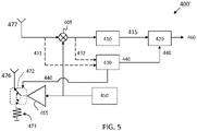
- Figure 5 schematically illustrates a second example of a radar transceiver 400' arranged to perform the techniques discussed herein.
- Figure 5 mainly corresponds to Figure 4 .
- the interference monitoring module 430 is connected to a second switch assembly 472 that is positioned between the PA 455 and the transmit antenna 476, and is adapted to switch the output of the PA 455 between the transmit antenna 476 and a resistive termination 473.
- a control signal 440 is generated which is adapted to control the switch assembly 472 to re-direct the radar signal transmission power to the resistive termination 473 as indicated with a dashed line.
- the control signal 440 is adapted to control the switch assembly 472 to restore connection between the PA 455 and the transmit antenna 476.
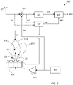
- Figure 6 schematically illustrates a third example of a radar transceiver 400" arranged to perform the techniques discussed herein.
- Figure 5 mainly corresponds to Figure 4 .
- the interference monitoring module 430 is connected to a beamforming arrangement 474 that is adapted to control antenna beams transmitted 475A, 475B by the transmit antenna 478.
- a main beam 475A In normal running, there is a main beam 475A that is directed in a first beam direction D1 as indicated with dashed lines.
- a control signal 440 is generated which is adapted to control the beamforming arrangement 474 to re-direct the radar signal transmission power in the air by re-directing, steering, the main beam 475B in a second beam direction D2 as indicated with dash-dotted lines, such that a the main beam 475B no longer is directed towards the interfering signal 180, an according to some aspects a null 479 is directed towards the interfering signal 180.
- the direction of the required null 479 can be ascertained by analysis of the interference signal arriving into the radar and adjusting the phase of the transmission antennas accordingly.
- the control signal 440 is adapted to control the beamforming arrangement 474 to restore the main beam 475A by directing it in the first beam direction D1 again.
- the transmit antenna 478 is constituted by an array antenna arrangement that enables beamforming and steering of antenna beams.
- both the transmit antenna 476, 478 and the receive antenna 477 can be constituted by one or more array antenna arrangements, where beamforming can be applied where applicable.
- the transmit antenna 476, 478 is constituted by a transmit antenna arrangement 476, 478
- the receive antenna 477 is constituted by a receive antenna arrangement 477.
- the main beam 475A, 475B may comprise several sub-beams, for example in the case of a multi-beam antenna.
- the beam directions D1, D2 relate to a corresponding resulting beam pointing directions D1, D2.
- antenna arrangements in general there are also a plurality of side-lobes.
- control signal 440 is also received by an ADC repair module 420 which is arranged to compensate for the re-direction of radar signal transmission power.
- the ADC repair module may, e.g., just apply an amplitude tapering to the received signal 415 in order to not affect FFT processing as much.
- the ADC repair module may also replace the received signal during the re-direction of radar signal transmission power by an ADC repair signal which will be discussed in more detail below in connection to Figures 7A-7E .
- the ADC repair module 420 may also compensate for the re-direction of transmission power by applying any of the repair methods disclosed in EP3489710 A1 , which discloses an arrangement for radar interference suppression based on replacing obtained radar samples by modified samples which are generated based on frequency domain processing of batches of samples.
- the chirp generator 450 is kept running regardless of whether the radar signal transmission power is re-directed or not.
- the input to the mixer 405 from the chirp generator i.e., a voltage controlled oscillator (VCO) or the like, can be left running during re-direction of radar signal transmission power such that the interference can be tracked as it traverses through the IF bandwidth by the receiver branch.
- VCO voltage controlled oscillator
- the ADC sampling 410 may be paused or its output not forwarded to further processing 460, since the interference is not of interest - this would be the missed section to fill in with repair methods.
- the ADC samples can of course be used to track the interfering signal as it traverses the IF bandwidth of the radar transceiver 400.
- FIG. 4-6 schematically illustrate a radar transceiver 400, 400', 400'' comprising a transmit branch TX, 450, 455, arranged to transmit a radar signal at a frequency F(t), and a receive branch RX, 405, 410, 420, 460 arranged to receive a radar signal.
- the receive branch also comprises an interference monitoring circuit 430 configured to monitor frequencies adjacent to the frequency F(t) for interference, and to generate a control signal 440 if interference is detected at the adjacent frequencies.
- the transmit branch is arranged to be controlled in response to the control signal 440 such that the radar signal transmission power is re-directed.
- the interference monitoring circuit 430 is configured to determine a cross-over time duration for the interference, and the radar signal transmission power is re-directed in response to the control signal 440 for the cross-over time duration.
- the cross-over time duration can be estimated from a relative frequency slope between the transmitted radar signal and the interfering radar signal, or it can be implicitly determined by monitoring the interference as it traverses the IF bandwidth of the receiver.
- Figures 7A-7C show graphs of an example baseband radar signal 415 amplitude A (over time t) in Volts, which illustrate an example of how the re-direction of radar signal transmission power can be compensated for by the ADC repair module 420.
- Figure 7A shows the received radar signal 415 at baseband or intermediate frequency.
- a part 510 of the received signal from time instant t 2 to time instant t 4 was subjected to interference and is therefore missing due to re-direction of radar signal transmission power as discussed above.
- This empty portion represents an abrupt jump in the signal level which may complicate object detection by, e.g., raising noise floor following FFT processing. It is desired to compensate for this missing signal section by repairing the baseband ADC signal 415.
- the received radar signal Since the received radar signal is narrow-band, it exhibits a degree of time correlation. It is therefore possible to 'predict' what it would have looked like based on a weighted combination of at least part of the received radar signal had the radar signal transmission power not been re-directed.
- This prediction 520 is illustrated in Figure 7B .
- the prediction can be obtained, e.g., as a weighted combination of the received radar signal outside 530, 540 of the interfered section 510.
- a gradient descent based method can be used to update finite impulse response (FIR) filter weights to obtain the weighted combination from filtering the received radar signal 415.
- FIR finite impulse response
- the filter design to generate the weighted combination can be based on some autoregressive model, and the filter weights can be updated based on, e.g., the Burg method.
- the sequence of time domain samples of the received radar signal 415 can be approximated or modelled by an autoregressive (AR) model.
- AR autoregressive
- An autoregressive model specifies that the output variable, i.e., the time domain samples x[n], depends linearly on the previous values and on a stochastic term (an imperfectly predictable term).
- the model is in the form of a stochastic difference equation. Together with the moving-average (MA) model, it is a special case and key component of the more general autoregressive moving average (ARMA) and autoregressive integrated moving average (ARIMA) models of time series.
- ARMA autoregressive moving average
- ARIMA autoregressive integrated moving average
- the weights of the filter a number of different known methods can be used.
- One such example is the Burg method, also sometimes referred to as the 'maximum entropy estimate'.
- the generation of the prediction signal can be performed in a particularly efficient manner based on a weighted combination of time domain samples before the interfered section 530 by using an adaptive finite impulse response (FIR) filter trained on the received radar signal 415.
- FIR adaptive finite impulse response
- the sequence of time domain samples can also be filtered in both forward F and reverse R directions as indicated in Figure 7D , i.e., predicting based on both past and future samples of the received radar signal 415 relative to the missing section 510.
- the forward filter filtering in direction F is likely to be more accurate and generate a smaller prediction error compared to the reverse filter filtering in direction R.
- the reverse is more likely to be the case, i.e., that the reverse filter generates a smaller error compared to the forward filter.
- the weighting can be linear as indicated in Figure 7D , where the forward filter weight w1 555 starts from 1.0, and then linearly declines to 0.0, while the reverse filter weight w2 565 starts from 0.0 and linearly increases up to 1.0.
- the two filter weights then always sum to one.
- the weighting can also be non-linear, e.g., based on a squared distance from the start of filtering.
- x1'[n] is the predicted sample from the forward filter
- x2'[n] is the predicted sample from the reverse filter.
- Figure 7E illustrates the prediction 520 obtained by merging the two filter outputs. It is noted that the forward filter (dash-dotted line) dominates the prediction to the left, while the reverse filter (dashed double-dotted line) dominates the prediction to the right.
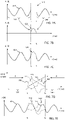
- Figure 8A shows an example interference situation where the interfering radar signal 180 has a similar frequency slope compared to the transmitted radar signal 210.
- the cross-over event 610 may extend over a long time duration 620, which is not preferred.
- the transmitted radar signal may be flipped such that the frequency change in the chirp is of different sign.
- Figure 8B illustrates a flipped transmitted radar signal 210'.
- the interfering radar signal 180 still has the same frequency slope. It is noted that the interference time duration is now much shorter.
- a method for interference mitigation comprising detection of an interfering radar signal associated with a frequency slope.
- the method evaluates a similarity between the frequency slope of the interfering radar signal and a transmitted radar signal.
- the method comprises re-parameterizing the transmitted radar waveform in order to shorten the cross-over time duration 620.
- the re-parameterizing may comprise flipping the frequency ramp, i.e., changing sign of the frequency derivative with respect to time.
- FIG. 9 shows a flow chart illustrating details of methods disclosed herein.
- the method comprises transmitting S1 a radar signal at a frequency F(t) and receiving S2 a radar signal.
- the received radar signal may comprise reflections 125 of interest due to objects 140 in vicinity of the radar transceiver 110 but also undesired interfering radio frequency signals, such as other radar signals 180.
- the transmitted radar signal is preferably but not necessarily a frequency modulated continuous wave (FMCW) radar signal.
- FMCW frequency modulated continuous wave
- the disclosed techniques are also applicable for a radar transceiver generating a wideband radar signal in a frequency band, e.g., an orthogonal frequency division multiplex (OFDM) radar transceiver. This type of transmission can also be re-directed in order to let an interfering signal associated with a frequency ramp pass.
- OFDM orthogonal frequency division multiplex
- the method comprises monitoring S3 frequencies adjacent to the frequency F(t) for interference.
- This monitoring may be focused on frequency bands adjacent to a receiving frequency band of the radar transceiver.
- the monitoring may also comprise determining a severity level of the interference. Only interference meeting some severity criteria would then cause re-direction of radar signal transmission power.
- the monitoring may, e.g., comprise filtering S31 the received radar signal to extract signal content at the adjacent frequencies.
- a filter bank can be used to filter out signal content in a number of different sub-bands adjacent to each other and to the receiving band of the radar transceiver 110.
- signal power will move between the different sub-band filters.
- This frequency ramp slope of the interfering signal 180 can be estimated if the shift in energy is clocked.
- This frequency slope (in terms of Hz per second) can then be used to determine a suitable re-direction time, i.e., an estimate of the cross-over time given the receiving bandwidth of the radar transceiver.
- the monitoring may also comprise wavelet transforming or Fourier transforming S32 the received radar signal. This way signal energy at frequencies adjacent to the receiving frequency band of the radar transceiver can be detected, which signal energy is indicative of the presence of an interfering radar signal 180.
- the wavelet and/or Fourier transform processing will also indicate at which rate the interfering signal approaches the receiving band of the radar transceiver. This rate of change can be used to estimate the cross-over time duration and therefore a suitable re-direction duration.
- Another way to detect interference is to monitor the received signal 415 for sudden jumps and irregularities indicating the presence of interference. These time instants can then be stored in memory and compared between different chirps. The time instances of interferences can then be used to predict when the next interference cross-over will occur, and also the time duration of this cross-over.
- the monitoring comprises storing previously received radar signal segments S33.
- the method determines S5 a cross-over time duration for the interference as discussed above and re-directs S6 radar signal transmission power for the cross-over time duration.
- a signal generator 450, oscillator, PLL, or the like in the radar transceiver 110, 400 may be kept running in order to maintain phase and frequency stability. This allows transmission to resume at the correct phase and frequency which would have been transmitted had the transmission power not been subject to re-directing.
- the cross-over time duration may, in a low complexity implementation, additionally be determined S55 as a fixed cross-over time duration.
- This fixed cross-over time duration can be preconfigured of adapted based on current interference scenario.
- the method comprises determining S51 a relative frequency gradient between the transmitted radar signal and an interfering radar signal. This relative frequency gradient, i.e., how fast the two signals are approaching each other in frequency, can be used to determine an adaptive cross-over time duration given the receiving bandwidth of the radar transceiver 110.
- determining S5 the cross-over time duration may also simply comprise the radar receiver tracking the interfering signal as it traverses the receive bandwidth of the radar transceiver. When the interfering signal exits the receive bandwidth, transmission can be resumed. Thus, determining S5 the cross-over time duration is not necessarily done in advance, but can be done as the interference actually occurs.
- determining S5 the cross-over time duration may also comprise randomizing the determined cross-over time duration. If both victim 100 and aggressor 190 implement the proposed technique of re-directing transmission power, there is a possibility that both radars are switched off simultaneously, which would be sub-optimal. To alleviate these effects, a random time back-off time before switching off transmission can be used, as well as random switch-back-on. This way, if the interference disappears before it reaches the receiving bandwidth of the radar transceiver, the transmission power need not be re-directed.
- the determined cross-over time duration may not necessarily correspond exactly to the time it takes for the interference to traverse the IF bandwidth, since it may also comprise a random perturbation for the reasons mentioned above.
- determining S5 the cross-over time duration may furthermore comprise applying a contention-based back-off routine S53.
- This would in a way be similar to a carrier sense multiple access system (CSMA) with collision detection (CD) features. Radar transceivers in vicinity of each other would monitor the adjacent frequency bands, i.e., adjacent to their receiving bands, for interference. If interference is present then the transmission power is re-directed with a randomized back-off period. If no interference is present or disappears due to the other transceiver having its transmission power re-directed, then transmission is allowed to continue without change.
- CSMA carrier sense multiple access system
- CD collision detection
- the method may also comprise re-configuring S54 a frequency derivative of the transmitted radar signal in dependence of parameters of the detected interference. This may mean that the sign of the frequency slope is switched, or that the frequency slope is changed in some way to avoid lengthy interference 620 with the interfering radar signal 180.
- re-directing S6 the radar signal transmission power may optionally comprise predicting and repairing S61 the received radar signal.
- the methods disclosed in EP3489710 A1 can also be used to cover up missing sections of the received radar signal which are due to re-directing radar signal transmission power.
- a less complex option of compensating for missing sections of the received radar signal is to apply an amplitude taper, or window function such as a Hamming window, to the received radar signal. This avoids jumps in the signal which could affect outputs of FFT processing in a negative way.
- re-directing the radar signal transmission power may according to some aspects comprise windowing S62 the received radar signal.
- re-directing S6 radar signal transmission power comprises at least one of:
- the method also comprises adjusting a transmission delay parameter of the transmitted radar signal in dependence of parameters of the detected interference. This way interference cross-over time instants can be shifted to the beginning or to the end of a chirp where the effects are not so severe.
- One alternative option for repairing the received radar signal in case interference is detected is to wait for the interference to exit the receive bandwidth, and then restart chirp transmission from the lowest frequency in the hope that this chirp, or block of chirps may be received free of interference.
- FIG 10 schematically illustrates, in terms of a number of functional units, the components of the radar transceiver 110 according to an embodiment.
- Processing circuitry 810 is provided using any combination of one or more of a suitable central processing unit (CPU), multiprocessor, microcontroller, digital signal processor (DSP), dedicated hardware accelerator, etc., capable of executing software instructions stored in a computer program product, e.g. in the form of a storage medium 830.
- the processing circuitry 810 may further be provided as at least one application specific integrated circuit (ASIC), or field programmable gate array (FPGA).
- ASIC application specific integrated circuit
- FPGA field programmable gate array
- the processing circuitry 810 is configured to cause the radar transceiver 110 to perform a set of operations, or steps. These operations, or steps, were discussed above in connection to Figure 9 .
- the storage medium 830 may store the set of operations
- the processing circuitry 810 may be configured to retrieve the set of operations from the storage medium 830 to cause the radar transceiver 110 to perform the set of operations.
- the set of operations may be provided as a set of executable instructions.
- the processing circuitry 810 is thereby arranged to execute methods as herein disclosed.
- the storage medium 830 may also comprise persistent storage, which, for example, can be any single one or combination of magnetic memory, optical memory, solid state memory or even remotely mounted memory.
- the radar transceiver 110 may further comprise a communications interface 820 for communications with at least one control unit 130, i.e., a radar interface 820.
- the radar interface 820 may comprise one or more transmitters and receivers, comprising analogue and digital components and a suitable number of ports for wired or wireless communication.
- the processing circuitry 810 is adapted to control the general operation of the radar transceiver 110 e.g. by sending data and control signals to the radar interface 720 and the storage medium 830, by receiving data and reports from the radar interface 820, and by retrieving data and instructions from the storage medium 830.
- Other components, as well as the related functionality, of the radar transceiver 110 are omitted in order not to obscure the concepts presented herein.
- Figure 11 shows a computer program product 900 comprising computer executable instructions 910 to execute any of the methods disclosed herein.
Landscapes
- Engineering & Computer Science (AREA)
- Radar, Positioning & Navigation (AREA)
- Remote Sensing (AREA)
- Computer Networks & Wireless Communication (AREA)
- Physics & Mathematics (AREA)
- General Physics & Mathematics (AREA)
- Electromagnetism (AREA)
- Radar Systems Or Details Thereof (AREA)
Description
- The present disclosure relates to interference in radar signals, and in particular to suppression of such interference. The radar systems discussed herein are suitable as vehicle radar systems.
- Many vehicle radar systems comprise radar transceivers that are arranged for generating radar signals that are transmitted, reflected and received by means of appropriate antennas comprised in the radar system. The radar signals may for example be in the form of FMCW (Frequency Modulated Continuous Wave) signals where frequency chirp signals are formed in a well-known manner.
- In a multi-radar environment, radars may interfere with each other as frequency chirps cross or come close to each other in frequency. When this happens, a burst of interference somewhere within the received signal during one or more of the chirp signals can be observed. This problem becomes apparent when the received analogue signal has been converted to a digital baseband signal and typically is processed by the radar system using one or more Fast Fourier Transform (FFT) processing steps which converts signals in digital time domain into digital frequency domain signals.
- If interference is present in one or more of the chirp signals, the noise floor will be raised since the noise may be spread across a wide band of frequencies. This raising of the noise floor has the effect of reducing the range and accuracy of the radar, which of course is undesirable.
-
EP3489710 A1 discloses an arrangement for radar interference suppression. Here, interference mitigation is achieved by replacing obtained radar samples by modified samples which are generated based on frequency domain processing of batches of samples. -
US 2007/188373 describes an automotive radar system which comprises an interference detection device. This interference detection device detects the presence of an interfering signal, whereupon a control device modifies one or more properties of the transmitted signal, such as its center frequency of bandwidth. -
US 2019/056476 discloses a radar unit that is configured to operate a time-discontinuous mode of operation that includes a first time portion used as an interference monitoring period and a second time portion used by the radar unit in the normal data acquisition mode of operation, where interference signals are detected during the monitoring period. -
US 2010/019950 discloses a radar system where a sampled beat signal is split into a plurality of short-time data and an interference component frequency is detected from a frequency spectrum of the short-time data. An absolute value of an incoming direction of interference components is estimated and is used when operating a filter for suppressing the interference components. -
US 2018/031674 relates to a phase modulated continuous wave (PMCW) radar system which comprises a form of in-band interference sensing mechanism, where the transmitter is briefly turned off in order to detect interference from nearby radar transceivers. -
WO 2019/106656 discloses a radar system based on time and frequency hopping, with a TX/RX control circuit that incorporates mutual interference detection. - However, additional interference suppression methods are desired.
- It is an object of the present disclosure to provide improved methods and devices for interference suppression in radar signals. This object is achieved by a method for suppressing interference in a radar transceiver. The method comprises transmitting a radar signal at a frequency F(t), receiving a radar signal, monitoring frequencies adjacent to the frequency F(t) for interference, and, if interference is detected (S4) in the adjacent frequencies and re-directing radar signal transmission power for a cross-over time duration. The cross-over time duration may be estimated by observing the aggressor signal prior to it appearing within the IF bandwidth or determined by monitoring it as it traverses across the IF bandwidth. The radar signal is a frequency modulated continuous wave (FMCW) radar signal having the frequency F(t). Determining the cross-over time duration comprises determining a relative frequency gradient between the transmitted radar signal and an interfering radar signal.
- This way interference to both the radar transceiver and the interfering radar transceiver is avoided, which is an advantage. The method can be used both to mitigate interference from legacy radar transmitters, and also to mitigate interference experienced by legacy radar transceivers. The proposed method is of relatively low complexity and requires no explicit communication between radar transceivers in order to synchronize radar transmission, which is an advantage.
- By determining a relative frequency gradient, it becomes possible to calculate the cross-over time duration in advance, given the IF bandwidth, without having to track the interference as it traverses across the receive frequency band of the radar transceiver.
- In addition, determining the cross-over time duration may also comprise tracking the interference as it crosses a receive bandwidth, or IF bandwidth, of the radar transceiver. The interference can be followed as it traverses the receive frequency band. Thus, the radar transceiver can determine when the interference is no longer present, i.e., having exited the IF bandwidth, whereby radar transmission can be resumed. Consequently, determining the cross-over time duration can be performed implicitly simply by detecting onset and cessation of the interference.
- According to aspects, the monitoring comprises filtering the received radar signal to detect signal content at the adjacent frequencies. Filtering is an efficient and robust method for detecting signal content at the adjacent frequencies. By using a filter bank, a frequency slope parameter of the interfering radar transmission can be robustly estimated, which is an advantage.
- According to aspects, the monitoring comprises wavelet transforming or Fourier transforming the received radar signal to detect signal content at the adjacent frequencies. Fourier transforming and/or Wavelet transforming provides a more accurate means for detecting and characterizing interference as it traverses over frequency. For instance, a relative or absolute frequency slope parameter of the interfering radar signal can be determined, from which the cross-over time duration can be estimated.
- According to aspects, the monitoring comprises storing previously received radar signal segments. By storing previously received radar signal samples it becomes possible to track and characterize one or more interfering radar signals as they cross different section of the transmitted radar signals. Depending on the relative frequency gradients of the transmitted radar signal and the interfering radar signal, the interference time instants will change from sweep to sweep, allowing the radar transceiver to characterize the interfering radar waveform in terms of at least relative frequency slope.
- In addition, determining the cross-over time duration may also comprise applying a contention-based back-off routine. If both victim and aggressor have the proposed system fitted, it would be sub-optimal if both radars switched off simultaneously. A random time back-off before switching off transmission may cover this eventuality, as well as random switch-back-on in case it is detected that the other transceiver also switched off - like a kind of mini contention resolution.
- In addition, determining the cross-over time duration may also comprise re-configuring a frequency derivative of the transmitted radar signal in dependence of parameters of the detected interference. By flipping the direction of the frequency sweep, the time duration of the cross-over event can be significantly shortened in some cases, which is an advantage. According to aspects, determining the cross-over time duration comprises determining a fixed cross-over time duration. Using a fixed cross-over time duration represents a low complexity option, which reduces computational burden on the overall system.
- According to aspects, re-directing the radar signal transmission power comprises predicting and repairing the received radar signal. By repairing the received signal, i.e., patching up the missing part, impact to further processing steps is reduced.
- According to aspects, re-directing radar signal transmission power comprises at least one of
- Re-directing the radar signal transmission power to a resistive termination before a power amplifier.
- Re-directing the radar signal transmission power to a resistive termination after a power amplifier and before a transmit antenna arrangement.
- Re-directing the radar signal transmission power in the air by adjusting relative RF phases within the transmit antenna arrangement such that a main beam is re-directed from a first resulting beam pointing direction to a second resulting beam pointing direction.
- In this way, radar signal transmission power can be re-directed in a safe and quick manner, very precisely causing a desired re-direction of radar signal transmission power that easily can be re-stored when suitable. No particular start-up or closing-down times are necessary.
- There are also disclosed herein radar transceivers and vehicles associated with the above-mentioned advantages. The herein disclosed methods may be executed in a vehicle or at least in part by a remote server wirelessly connected to the vehicle.
- The present disclosure will now be described more in detail with reference to the appended drawings, where:
-
Figure 1 shows a schematic top view of vehicles; -
Figure 2 shows an example of a transmitted radar signal; -
Figure 3 schematically illustrates radar interference; -
Figure 4 schematically illustrates a first example of a radar transceiver; -
Figure 5 schematically illustrates a second example of a radar transceiver; -
Figure 6 schematically illustrates a third example of a radar transceiver; -
Figures 7A-E illustrates radar signal repair; -
Figures 8A-B illustrates example radar signal transmissions; -
Figure 9 is a flowchart illustrating methods; -
Figure 10 shows an example control unit; and -
Figure 11 shows an example computer program product. - The inventive concept will now be described more fully hereinafter with reference to the accompanying drawings, in which certain embodiments of the inventive concept are shown. This inventive concept may, however, be embodied in many different forms and should not be construed as limited to the embodiments set forth herein, as long as said forms fall within the scope of protection as defined by the appended claims; rather, these embodiments are provided by way of example so that this disclosure will be thorough and complete, and will fully convey the scope of the inventive concept to those skilled in the art. Like numbers refer to like elements throughout the description. Any step or feature illustrated by dashed lines should be regarded as optional.
-
Figure 1 shows avehicle 100 equipped with avehicle radar system vehicle radar transceiver 110 and a radar data processing system orcontrol unit 130. It is appreciated that theradar transceiver 110 and thecontrol unit 130 may be comprised in a single physical unit or may be distributed over more than one physical unit. Some parts of the functionality may even be comprised in aremote server 160 connected to the vehicle viawireless link 150. - According to an example, the
vehicle radar system object 140. - As exemplified in
Figure 2 , a transmitted FMCW signal is in the form of a continuous wave where the output frequency F(t) varies from a first frequency fstart to a second frequency fstop over the course of a ramp r. Most FMCW transmissions comprise repeating cycles of a plurality of frequency ramps r as shown inFigure 2 , however, some radar transmissions only comprise one slow chirp, i.e., different from the example transmission ofFigure 2 . A cycle for such a chirp signal lasts for a certain cycle time tc, each ramp r lasts a certain ramp time tr, having a ramp period time tT. Between two consecutive ramps of the chirp signal there is often inserted a delay time tD. - FMCW radar operation and signal processing is known in general and will not be discussed in more detail herein.
- With reference again to
Figure 1 , the radardata processing system 130 is arranged to control operation of theradar transceiver 110, and to obtain data from theradar transceiver 110, such as detections or data points corresponding toobjects 140 in vicinity of thevehicle 100. - The
radar transceiver 110 may comprise a single radar unit or a plurality of radar units, potentially of different type and/or of different configuration. The different radar units may, e.g., be arranged as front radars, side radars, and/or rearward facing radars. - The
radar transceiver 110 is associated with a field ofview 120. In case theradar transceiver 110 is a front radar, aboresight direction 121 of theradar 110 often coincides with a center line of the field ofview 120. In case the vehicle radar is instead configured as a side radar, then the boresight direction may point in some other angle compared to the forward direction of thevehicle 100. - The
vehicle radar system Figure 1 is subject tointerference 180 from an external radar transceiver. Such interference can come from a plurality of different sources, including other radar transceivers on thesame vehicle 100. - For an FMCW system, interference occurs when two or more radar signals 180, 210 are close together in frequency for a period of time, specifically within the intermediate frequency (IF) receiving bandwidth of each other or cross each other in frequency. The net effect is that the time domain signal, i.e., the raw data or digitally sampled signal obtained after frequency down-conversion of the received radio frequency signal, experiences a burst of interference, which may be high compared to the wanted radar-return signal. There may be multiple interference bursts within a short time window.
- It is appreciated that the term 'interference' is here to be interpreted broadly to comprise any signal component or signal comprised in the radar signal which has a detrimental effect on performance of a system making use of the received radar signal. Consequently, interference may comprise any of, e.g., external interference from other transmitters and radio frequency sources, internal interference from circuitry of the radar transceiver or other active components located close to the radar receiver, and pulsed interference signals which are associated with limited time duration. Nevertheless, the techniques disclosed herein are particularly suitable for mitigating interference caused by an interfering FMCW transceiver.
- As noted above, the vehicle radar system 110,130 may be connected via
wireless link 150 to aremote server 160, which in turn may be comprised in aremote network 170. This server and network may be configured to assist thevehicle 100 in performing radar interference suppression. For instance, theremote server 160 may be arranged to configure parameters such as detection thresholds used by thecontrol unit 130 and the like remotely, and also transmission parameters of the radar transceiver, such as frequency slopes and the like. - An optional storage module may also be comprised in the vehicle radar system. The storage module may store data comprising information about a surrounding environment of the
vehicle 100 and about past vehicle operations, such as past experiences of radar interference and radar interference suppression operations. The storage module will be discussed in more detail below in connection toFigure 10 . -
Figure 3 illustrates two FMCW radar signals 210, 180, where theradar signal 210 may be a chirp from the sequence ofchirps 200 illustrated inFigure 2 . Thus, theradar signal 210 may correspond to a radar signal transmitted by thevehicle 100, whileradar signal 180 is an interfering radar signal. The two radar signals have different frequency slopes, i.e., the frequency change with respect to time is different for the two signals. The two radar signals therefore cross each other at a crossing 330 at time t3, whereupon interference occurs (to both signals). - A radar transceiver, such as the
radar transceiver 110 is often associated with a receiving bandwidth in which signals are received, sometimes referred to as the intermediate frequency (IF) bandwidth of the radar transceiver. Radio frequency signals received outside of this bandwidth are filtered out by the receiver. For an FMCW transceiver, the frequency location of the IF band moves linearly over time together with the transmitted center frequency. The IFbandwidth 370 of theradar transceiver 110 is indicated inFigure 3 . It is appreciated that the figure illustrates the case for a single channel mixer (only the I-channel or "real"). In the case of a quadrature down-conversion comprising I and Q outputs, it is understood that the upper and lower sidebands could be available separately at the processor as explained inUS2019011533 , but the general concept illustrated here would of course still be valid. - With reference to
Figure 3 , the interferingradar signal 180 enters the IF bandwidth of theradar signal 210 at time t2, and therefore starts to interfere with theradar signal 210. This interference continues past the point in time t3 when the crossing 330 occurs until the interfering radar signal leaves the IF bandwidth of theradar signal 210 at anexit point 360, which occurs at time t4. Consequently, theradar signal 210 suffers from interference at least during a cross-over time duration from anentry point 350 at time t2 to theexit point 360 at time t4. - The time it takes for the interfering
radar signal 180 to cross the IF bandwidth of the transmittedradar signal 210 is obtained as the IF bandwidth (in Hz) divided by the relative frequency slope of the two waveforms (in Hz/sec). - However, this interference need not come as a surprise to the radar transceiver. Frequencies adjacent to the IF bandwidth of the radar transceiver can be monitored. If the radar transceiver continuously or intermittently monitors frequency bands above 372 and below 371 the
IF frequency band 370, then the interferingradar signal 180 can be detected before interference occurs. In order to avoid being interfered by the other radar signal, theradar transceiver 110 may re-direct its radar signal transmission power during the cross-over time duration for the interference for example by re-directing radar signal transmission power towards a resistive termination before reaching a transmitantenna 476 as shown inFigure 4 andFigure 5 , or by steering radar signal transmission power in another angular direction as shown inFigure 6 . These examples will be described more in detail later. - When radar transmission power is re-directed, the receive chain of the
radar transceiver 110 may either be turned off completely so that nothing is received (including both desired and interfering signal) or be left on in order to monitor or track the interfering signal as it traverses the receive band. In case the receiver is left on, the data would of course not be retained for further processing, but discarded, since there is no useful transmission from the system at this time. Also, by re-directing radar transmission power, no interference is generated at the other radar transceiver, thus sparing also the interfering radar transceiver. It is an advantage that the proposed method not only spares theradar transceiver 110 from interference, but also the interfering radar transceiver. - It is appreciated that the interference can be of varying severity, i.e., comprise more or less energy. Strong interference may have a profound impact on detection performance, while weaker interference could be tolerable in some scenarios. According to some aspects the techniques disclosed herein also comprises determining a severity level of the interference, and only re-directing transmission power if the interference meets some severity criteria. For instance, a threshold on interference power can be set, and only such interference associated with a power above the threshold would then trigger re-directing of transmission power. The threshold can be fixed or adapted during radar operation. For instance, the threshold can start out relatively low in a sequence of chirps and increase each time transmission power is re-directed. This way it can be ensured that the transmitted signal transmission power is not re-directed too often. Also, the threshold can be set in dependence of the traffic scenario, and/or in dependence of the interference scenario.
- By re-directing radar signal transmission power from onset to cessation of radar interference, a discontinuity is generated in the transmitted waveform. Hence, the disclosed technique comprises discontinuous radar transmission in the sense that the transmission power may be re-directed from time to time as interfering radar signals traverse the IF bandwidth of the
radar transceiver 110. -
Figure 3 exemplifies this interference mitigation technique; the interferingradar signal 180 is detected between time t1 and time t2 as it enters afrequency band 371 adjacent to theIF frequency band 370. Following detection of the interfering radar signal, the radar signal transmission power is re-directed, shown inFigure 3 by a dotted line, and then restored again sometime around time t4 when the interference is no longer present in the receiving bandwidth of the transceiver. Notably, internal signal generation preferably continues to be active in order to maintain phase stability, frequency stability, and the like, so that signal transmission can be restored again without phase jumps once the interference has exited the IF bandwidth. Such effects are well known problems when there are transients on the voltage supply brought about by abrupt changes in power consumption. - In other words,
Figure 3 shows an example of a method where avictim transceiver 110 first detects anaggressor 190 within a monitoring bandwidth of the receiver. As the aggressor enters the IF bandwidth of the victim, the victim re-directs transmission power, but maintains chirp generation. When the aggressor signal again leaves the IF bandwidth of the victim, the victim transmission is resumed. - It is noted that if both victim and aggressor have this system fitted, it would be sub-optimal if both radars switched off simultaneously. A random time back-off before switching off transmission may cover this eventuality, as well as random switch-back-on in case it is detected that the other transceiver also switched off - like a kind of mini contention resolution.
- Optionally, the victim, i.e., the
radar transceiver 110, may send a short modulated signal on top of the chirp indicating that it will momentarily switch off. This could be a digital message which is phase modulated on the carrier or it could be an analogue fade-out, or it could be the chirp stopping at the current continuous wave (CW) frequency (still transmitting for a period), while the phase locked loop (PLL) continues to generate the un-transmitted chirp (since this will be used to pick-up where it left off after the aggressor has passed). Alternatively, the radar transceivers may signal intent and actions via some other communication channel, e.g., via vehicle to vehicle (V2V) communications or via theremote server 160. -
Figure 4 schematically illustrates a first example of aradar transceiver 400 arranged to perform the techniques discussed herein. Achirp generator 450 generates the radar signal for transmission. The radar signal is amplified by a power amplifier (PA) 455, before being transmitted from the transmitantenna 476. Radar signals comprising reflected radar signals and any interfering signals are received via a receiveantenna 477. The received radio frequency signals are down-converted by amixer 405 and then filtered and digitized 410 by an analog to digital converter (ADC). Before being forwarded forfurther signal processing 460 comprising, e.g., Fast Fourier Transform processing (FFT) and the like. - The
radar transceiver 400 shown inFigure 4 also comprises aninterference monitoring module 430. Thisinterference monitoring module 430 monitors signal occupancy infrequency bands radar transceiver 400, i.e., the IF band. Theinterference monitoring module 430 may monitor the received signal atradio frequency 431 and/or after downconversion 432 and is connected to afirst switch assembly 470 that is positioned between thechirp generator 450 between thePA 455 and is adapted to switch the output of thechirp generator 450 between thePA 455 and aresistive termination 471. In normal running state, theswitch assembly 470 directs the output of thechirp generator 450 to thePA 455 as indicated with a solid line. - In case an interfering signal is detected as it enters the monitored
frequency bands control signal 440 is generated which is adapted to control theswitch assembly 470 to re-direct the radar signal transmission power to theresistive termination 471 as indicated with a dashed line. When the interfering signal has been determined to have left the monitoredfrequency bands control signal 440 is adapted to control theswitch assembly 470 to restore connection between thechirp generator 450 and thePA 455. -
Figure 5 schematically illustrates a second example of a radar transceiver 400' arranged to perform the techniques discussed herein.Figure 5 mainly corresponds toFigure 4 . Here, however, theinterference monitoring module 430 is connected to asecond switch assembly 472 that is positioned between thePA 455 and the transmitantenna 476, and is adapted to switch the output of thePA 455 between the transmitantenna 476 and aresistive termination 473. - In the same manner as in the first example, in case an interfering signal is detected as it enters the monitored
frequency bands control signal 440 is generated which is adapted to control theswitch assembly 472 to re-direct the radar signal transmission power to theresistive termination 473 as indicated with a dashed line. When the interfering signal has been determined to have left the monitoredfrequency bands control signal 440 is adapted to control theswitch assembly 472 to restore connection between thePA 455 and the transmitantenna 476. -
Figure 6 schematically illustrates a third example of aradar transceiver 400" arranged to perform the techniques discussed herein.Figure 5 mainly corresponds toFigure 4 . Here, however, theinterference monitoring module 430 is connected to abeamforming arrangement 474 that is adapted to control antenna beams transmitted 475A, 475B by the transmitantenna 478. In normal running, there is amain beam 475A that is directed in a first beam direction D1 as indicated with dashed lines. - In case an interfering
signal 180 is detected as it enters the monitoredfrequency bands control signal 440 is generated which is adapted to control thebeamforming arrangement 474 to re-direct the radar signal transmission power in the air by re-directing, steering, themain beam 475B in a second beam direction D2 as indicated with dash-dotted lines, such that a themain beam 475B no longer is directed towards the interferingsignal 180, an according to some aspects a null 479 is directed towards the interferingsignal 180. The direction of the required null 479 can be ascertained by analysis of the interference signal arriving into the radar and adjusting the phase of the transmission antennas accordingly. - When the interfering
signal 180 has been determined to have left the monitoredfrequency bands control signal 440 is adapted to control thebeamforming arrangement 474 to restore themain beam 475A by directing it in the first beam direction D1 again. For the third example, the transmitantenna 478 is constituted by an array antenna arrangement that enables beamforming and steering of antenna beams. - According to some aspects, for all examples, it is to be noted that both the transmit
antenna antenna 477 can be constituted by one or more array antenna arrangements, where beamforming can be applied where applicable. Generally, the transmitantenna antenna arrangement antenna 477 is constituted by a receiveantenna arrangement 477. Themain beam - As for antenna arrangements in general, there are also a plurality of side-lobes.
- According to some aspects, any combination of the above examples is of course conceivable.
- According to some aspects, for all examples above, the
control signal 440 is also received by anADC repair module 420 which is arranged to compensate for the re-direction of radar signal transmission power. The ADC repair module may, e.g., just apply an amplitude tapering to the receivedsignal 415 in order to not affect FFT processing as much. However, the ADC repair module may also replace the received signal during the re-direction of radar signal transmission power by an ADC repair signal which will be discussed in more detail below in connection toFigures 7A-7E . - The
ADC repair module 420 may also compensate for the re-direction of transmission power by applying any of the repair methods disclosed inEP3489710 A1 , which discloses an arrangement for radar interference suppression based on replacing obtained radar samples by modified samples which are generated based on frequency domain processing of batches of samples. - Notably, the
chirp generator 450 is kept running regardless of whether the radar signal transmission power is re-directed or not. - The input to the
mixer 405 from the chirp generator, i.e., a voltage controlled oscillator (VCO) or the like, can be left running during re-direction of radar signal transmission power such that the interference can be tracked as it traverses through the IF bandwidth by the receiver branch. However, theADC sampling 410 may be paused or its output not forwarded to further processing 460, since the interference is not of interest - this would be the missed section to fill in with repair methods. However, the ADC samples can of course be used to track the interfering signal as it traverses the IF bandwidth of theradar transceiver 400. - To summarize,
Figure 4-6 schematically illustrate aradar transceiver 400, 400', 400'' comprising a transmit branch TX, 450, 455, arranged to transmit a radar signal at a frequency F(t), and a receive branch RX, 405, 410, 420, 460 arranged to receive a radar signal. The receive branch also comprises aninterference monitoring circuit 430 configured to monitor frequencies adjacent to the frequency F(t) for interference, and to generate acontrol signal 440 if interference is detected at the adjacent frequencies. The transmit branch is arranged to be controlled in response to thecontrol signal 440 such that the radar signal transmission power is re-directed. - According to some aspects, the
interference monitoring circuit 430 is configured to determine a cross-over time duration for the interference, and the radar signal transmission power is re-directed in response to thecontrol signal 440 for the cross-over time duration. As mentioned above, the cross-over time duration can be estimated from a relative frequency slope between the transmitted radar signal and the interfering radar signal, or it can be implicitly determined by monitoring the interference as it traverses the IF bandwidth of the receiver. -
Figures 7A-7C show graphs of an examplebaseband radar signal 415 amplitude A (over time t) in Volts, which illustrate an example of how the re-direction of radar signal transmission power can be compensated for by theADC repair module 420.Figure 7A shows the receivedradar signal 415 at baseband or intermediate frequency. Apart 510 of the received signal from time instant t2 to time instant t4 was subjected to interference and is therefore missing due to re-direction of radar signal transmission power as discussed above. This empty portion represents an abrupt jump in the signal level which may complicate object detection by, e.g., raising noise floor following FFT processing. It is desired to compensate for this missing signal section by repairing thebaseband ADC signal 415. Since the received radar signal is narrow-band, it exhibits a degree of time correlation. It is therefore possible to 'predict' what it would have looked like based on a weighted combination of at least part of the received radar signal had the radar signal transmission power not been re-directed. Thisprediction 520 is illustrated inFigure 7B . The prediction can be obtained, e.g., as a weighted combination of the received radar signal outside 530, 540 of the interferedsection 510. - A gradient descent based method can be used to update finite impulse response (FIR) filter weights to obtain the weighted combination from filtering the received
radar signal 415. This method provides a somewhat computationally expensive yet accurate way to determine suitable filter weights. Alternatively, the filter design to generate the weighted combination can be based on some autoregressive model, and the filter weights can be updated based on, e.g., the Burg method. In general, the sequence of time domain samples of the receivedradar signal 415 can be approximated or modelled by an autoregressive (AR) model. An autoregressive model specifies that the output variable, i.e., the time domain samples x[n], depends linearly on the previous values and on a stochastic term (an imperfectly predictable term). The model is in the form of a stochastic difference equation. Together with the moving-average (MA) model, it is a special case and key component of the more general autoregressive moving average (ARMA) and autoregressive integrated moving average (ARIMA) models of time series. - To find the coefficients on an AR model, here the weights of the filter, a number of different known methods can be used. One such example is the Burg method, also sometimes referred to as the 'maximum entropy estimate'.
- This way, if radar signal transmission power is re-directed during a cross-over time duration, the missing
section 510 due to the re-directing can be replaced by theprediction 520, as illustrated inFigure 7C . This way the ADC signal can be 'repaired' and the missing section due to the re-directing can be compensated for in an efficient and reliable manner, which is an objective of the herein disclosed techniques. Since the radar signal transmission power is re-directed, the interfering radar transceiver is also spared from interference. - Notably, the generation of the prediction signal can be performed in a particularly efficient manner based on a weighted combination of time domain samples before the interfered
section 530 by using an adaptive finite impulse response (FIR) filter trained on the receivedradar signal 415. - The sequence of time domain samples can also be filtered in both forward F and reverse R directions as indicated in
Figure 7D , i.e., predicting based on both past and future samples of the receivedradar signal 415 relative to the missingsection 510. The forward filter which filterpast samples 530 generates one set of predictedsamples 550, shown as a dash-dotted line, and the reverse filter which filtersfuture samples 540 in the reverse direction R generates another set of predictedsamples 560 shown as a dashed double-dotted line. The longer into the interferedsection 510 that each filter progresses, the larger the prediction error is likely to become. - I.e., at the beginning of the
missing part 510, the forward filter filtering in direction F is likely to be more accurate and generate a smaller prediction error compared to the reverse filter filtering in direction R. At the end of themissing part 510, the reverse is more likely to be the case, i.e., that the reverse filter generates a smaller error compared to the forward filter. It is proposed herein to merge the two filter outputs by weighting each filter output according to how long into the interfered part the current sample is. The weighting can be linear as indicated inFigure 7D , where the forward filter weight w1 555 starts from 1.0, and then linearly declines to 0.0, while the reverse filter weight w2 565 starts from 0.0 and linearly increases up to 1.0. The two filter weights then always sum to one. The weighting can also be non-linear, e.g., based on a squared distance from the start of filtering. In such case the filter weights can be determined as w1=d12/(w1+w2), w2=d22/(w1+w2), where d1 and d2 represent the distance to the predicted sample from the start of themissing part 510 and the end of the interfered part, respectively. - The predicted sample x'[n] for predicting a current sample x[n] may be determined as x'[n]=w1*x1'[n]+w2*x2'[n] (assuming normalized weights w1 and w2), where x1'[n] is the predicted sample from the forward filter and x2'[n] is the predicted sample from the reverse filter. This way a type of "cross-fading" is performed when combining the signal estimate or prediction in forward direction with the reverse direction to get a signal that has no jumps and meets neatly in the middle of the missing
section 510.Figure 7E illustrates theprediction 520 obtained by merging the two filter outputs. It is noted that the forward filter (dash-dotted line) dominates the prediction to the left, while the reverse filter (dashed double-dotted line) dominates the prediction to the right. -
Figure 8A shows an example interference situation where the interferingradar signal 180 has a similar frequency slope compared to the transmittedradar signal 210. In this case thecross-over event 610 may extend over along time duration 620, which is not preferred. To improve the interference conditions, the transmitted radar signal may be flipped such that the frequency change in the chirp is of different sign.Figure 8B illustrates a flipped transmitted radar signal 210'. The interferingradar signal 180 still has the same frequency slope. It is noted that the interference time duration is now much shorter. - It is appreciated that the slope reversal function illustrated in
Figures 8A and 8B can be implemented independently of the other features discussed herein. Thus, there is disclosed herein a method for interference mitigation comprising detection of an interfering radar signal associated with a frequency slope. The method evaluates a similarity between the frequency slope of the interfering radar signal and a transmitted radar signal. In case the interference duration, i.e., the time it takes for the two radar signal to cross each other, is too long, the method comprises re-parameterizing the transmitted radar waveform in order to shorten thecross-over time duration 620. The re-parameterizing may comprise flipping the frequency ramp, i.e., changing sign of the frequency derivative with respect to time.Figure 9 shows a flow chart illustrating details of methods disclosed herein. There is shown a method for suppressing interference in aradar transceiver 110. The method comprises transmitting S1 a radar signal at a frequency F(t) and receiving S2 a radar signal. The received radar signal may comprisereflections 125 of interest due toobjects 140 in vicinity of theradar transceiver 110 but also undesired interfering radio frequency signals, such as other radar signals 180. The transmitted radar signal is preferably but not necessarily a frequency modulated continuous wave (FMCW) radar signal. Notably, the disclosed techniques are also applicable for a radar transceiver generating a wideband radar signal in a frequency band, e.g., an orthogonal frequency division multiplex (OFDM) radar transceiver. This type of transmission can also be re-directed in order to let an interfering signal associated with a frequency ramp pass. - The method comprises monitoring S3 frequencies adjacent to the frequency F(t) for interference. This monitoring may be focused on frequency bands adjacent to a receiving frequency band of the radar transceiver. As mentioned above, the monitoring may also comprise determining a severity level of the interference. Only interference meeting some severity criteria would then cause re-direction of radar signal transmission power.
- The monitoring may, e.g., comprise filtering S31 the received radar signal to extract signal content at the adjacent frequencies. In case signal power is detected in a band adjacent to the receiving band of the radar transceiver, there is an indication that interference is present, and that action should be taken. A filter bank can be used to filter out signal content in a number of different sub-bands adjacent to each other and to the receiving band of the
radar transceiver 110. As an interfering FMCW signal approaches the receiving band of theradar transceiver 110, signal power will move between the different sub-band filters. This way the frequency ramp slope of the interferingsignal 180 can be estimated if the shift in energy is clocked. This frequency slope (in terms of Hz per second) can then be used to determine a suitable re-direction time, i.e., an estimate of the cross-over time given the receiving bandwidth of the radar transceiver. - The monitoring may also comprise wavelet transforming or Fourier transforming S32 the received radar signal. This way signal energy at frequencies adjacent to the receiving frequency band of the radar transceiver can be detected, which signal energy is indicative of the presence of an interfering
radar signal 180. The wavelet and/or Fourier transform processing will also indicate at which rate the interfering signal approaches the receiving band of the radar transceiver. This rate of change can be used to estimate the cross-over time duration and therefore a suitable re-direction duration. - Another way to detect interference is to monitor the received
signal 415 for sudden jumps and irregularities indicating the presence of interference. These time instants can then be stored in memory and compared between different chirps. The time instances of interferences can then be used to predict when the next interference cross-over will occur, and also the time duration of this cross-over. In other words, according to aspects, the monitoring comprises storing previously received radar signal segments S33. - If interference is detected S4 in the adjacent frequencies, the method determines S5 a cross-over time duration for the interference as discussed above and re-directs S6 radar signal transmission power for the cross-over time duration. Notably, a
signal generator 450, oscillator, PLL, or the like in theradar transceiver - The cross-over time duration may, in a low complexity implementation, additionally be determined S55 as a fixed cross-over time duration. This fixed cross-over time duration can be preconfigured of adapted based on current interference scenario. In accordance with the appended independant claims, the method comprises determining S51 a relative frequency gradient between the transmitted radar signal and an interfering radar signal. This relative frequency gradient, i.e., how fast the two signals are approaching each other in frequency, can be used to determine an adaptive cross-over time duration given the receiving bandwidth of the
radar transceiver 110. - In addition, determining S5 the cross-over time duration may also simply comprise the radar receiver tracking the interfering signal as it traverses the receive bandwidth of the radar transceiver. When the interfering signal exits the receive bandwidth, transmission can be resumed. Thus, determining S5 the cross-over time duration is not necessarily done in advance, but can be done as the interference actually occurs.
- In addition, determining S5 the cross-over time duration may also comprise randomizing the determined cross-over time duration. If both
victim 100 andaggressor 190 implement the proposed technique of re-directing transmission power, there is a possibility that both radars are switched off simultaneously, which would be sub-optimal. To alleviate these effects, a random time back-off time before switching off transmission can be used, as well as random switch-back-on. This way, if the interference disappears before it reaches the receiving bandwidth of the radar transceiver, the transmission power need not be re-directed. In other words, the determined cross-over time duration may not necessarily correspond exactly to the time it takes for the interference to traverse the IF bandwidth, since it may also comprise a random perturbation for the reasons mentioned above. - In addition, determining S5 the cross-over time duration may furthermore comprise applying a contention-based back-off routine S53. This would in a way be similar to a carrier sense multiple access system (CSMA) with collision detection (CD) features. Radar transceivers in vicinity of each other would monitor the adjacent frequency bands, i.e., adjacent to their receiving bands, for interference. If interference is present then the transmission power is re-directed with a randomized back-off period. If no interference is present or disappears due to the other transceiver having its transmission power re-directed, then transmission is allowed to continue without change.
- As discussed in connection to
Figure 8A and 8B above, the method may also comprise re-configuring S54 a frequency derivative of the transmitted radar signal in dependence of parameters of the detected interference. This may mean that the sign of the frequency slope is switched, or that the frequency slope is changed in some way to avoidlengthy interference 620 with the interferingradar signal 180. - As discussed above in connection to
Figures 7A-7E , re-directing S6 the radar signal transmission power may optionally comprise predicting and repairing S61 the received radar signal. The methods disclosed inEP3489710 A1 can also be used to cover up missing sections of the received radar signal which are due to re-directing radar signal transmission power. - A less complex option of compensating for missing sections of the received radar signal is to apply an amplitude taper, or window function such as a Hamming window, to the received radar signal. This avoids jumps in the signal which could affect outputs of FFT processing in a negative way. In other words, re-directing the radar signal transmission power may according to some aspects comprise windowing S62 the received radar signal.
- According to some aspects, re-directing S6 radar signal transmission power comprises at least one of:
- Re-directing S63 the radar signal transmission power to a
resistive termination 471 before apower amplifier 455. - Re-directing S64 the radar signal transmission power to a
resistive termination 473 after apower amplifier 455 and before a transmitantenna arrangement 476. - Re-directing S65 the radar signal transmission power in the air by adjusting relative phases of the transmit
antenna arrangement 478 such that amain beam 475A is re-directed from a first resulting beam pointing direction D1 to a second resulting beam pointing direction D2. - An FMCW signal is often windowed prior to FFT processing. This means that the signal is amplitude tapered at the beginning and at the end in order to avoid large signal jumps which may have a negative effect on the output of FFT post-processing. Consequently, if interference occurs at the beginning of the chirp, or at the very end, then interference effects are not so severe. According to some aspects, the method also comprises adjusting a transmission delay parameter of the transmitted radar signal in dependence of parameters of the detected interference. This way interference cross-over time instants can be shifted to the beginning or to the end of a chirp where the effects are not so severe.
- One alternative option for repairing the received radar signal in case interference is detected is to wait for the interference to exit the receive bandwidth, and then restart chirp transmission from the lowest frequency in the hope that this chirp, or block of chirps may be received free of interference.
-
Figure 10 schematically illustrates, in terms of a number of functional units, the components of theradar transceiver 110 according to an embodiment.Processing circuitry 810 is provided using any combination of one or more of a suitable central processing unit (CPU), multiprocessor, microcontroller, digital signal processor (DSP), dedicated hardware accelerator, etc., capable of executing software instructions stored in a computer program product, e.g. in the form of astorage medium 830. Theprocessing circuitry 810 may further be provided as at least one application specific integrated circuit (ASIC), or field programmable gate array (FPGA). - Particularly, the
processing circuitry 810 is configured to cause theradar transceiver 110 to perform a set of operations, or steps. These operations, or steps, were discussed above in connection toFigure 9 . For example, thestorage medium 830 may store the set of operations, and theprocessing circuitry 810 may be configured to retrieve the set of operations from thestorage medium 830 to cause theradar transceiver 110 to perform the set of operations. The set of operations may be provided as a set of executable instructions. Thus, theprocessing circuitry 810 is thereby arranged to execute methods as herein disclosed. - The
storage medium 830 may also comprise persistent storage, which, for example, can be any single one or combination of magnetic memory, optical memory, solid state memory or even remotely mounted memory. - The
radar transceiver 110 may further comprise acommunications interface 820 for communications with at least onecontrol unit 130, i.e., aradar interface 820. As such, theradar interface 820 may comprise one or more transmitters and receivers, comprising analogue and digital components and a suitable number of ports for wired or wireless communication. - The
processing circuitry 810 is adapted to control the general operation of theradar transceiver 110 e.g. by sending data and control signals to the radar interface 720 and thestorage medium 830, by receiving data and reports from theradar interface 820, and by retrieving data and instructions from thestorage medium 830. Other components, as well as the related functionality, of theradar transceiver 110 are omitted in order not to obscure the concepts presented herein. -
Figure 11 shows acomputer program product 900 comprising computerexecutable instructions 910 to execute any of the methods disclosed herein.
Claims (13)
- A method for suppressing interference in a radar transceiver (110), the method comprisingtransmitting (S1) a radar signal at a frequency F(t), receiving (S2) a radar signal,monitoring (S3) frequencies adjacent to the frequency F(t) for interference, and, if interference is detected (S4) in the adjacent frequencies,determining (S5) a cross-over time duration for the interference, andre-directing (S6) radar signal transmission power for the cross-over time duration,where the transmitting comprises transmitting (S11) a frequency modulated continuous wave, FMCW, radar signal having the frequency F(t), andwherein determining the cross-over time duration comprises determining (S51) a relative frequency gradient between the transmitted radar signal and an interfering radar signal.
- The method according to claim 1 wherein the monitoring comprises filtering (S31) the received radar signal to detect signal content at the adjacent frequencies.
- The method according to any previous claim, wherein the monitoring comprises wavelet transforming or Fourier transforming (S32) the received radar signal to detect signal content at the adjacent frequencies.
- The method according to any previous claim, wherein the monitoring comprises storing previously received radar signal segments (S33).
- The method according to any previous claim, wherein determining the cross-over time duration comprises tracking the interference as it crosses a receive bandwidth of the radar transceiver (110).
- The method according to any previous claim, wherein determining the cross-over time duration comprises applying a contention-based back-off routine (S53).
- The method according to any previous claim, wherein determining the cross-over time duration comprises re-configuring (S54) a frequency derivative of the transmitted radar signal in dependence of parameters of the detected interference.
- The method according to any of claims 1-5, wherein determining the cross-over time duration comprises determining (S55) a fixed cross-over time duration.
- The method according to any previous claim, wherein re-directing (S6) the radar signal transmission power comprises predicting and repairing (S61) the received radar signal.
- The method according to any previous claim, wherein re-directing (S6) radar signal transmission power comprises at least one of:re-directing (S63) the radar signal transmission power to a resistive termination (471) before a power amplifier (455);re-directing (S64) the radar signal transmission power to a resistive termination (473) after a power amplifier (455) and before a transmit antenna arrangement (476);re-directing (S65) the radar signal transmission power in the air by adjusting relative RF phases within the transmit antenna arrangement (478) such that a main beam (475A) is re-directed from a first resulting beam pointing direction (D1) to a second resulting beam pointing direction (D2).
- A radar transceiver (110, 400) comprising a transmit branch (450, 455, TX) arranged to transmit a radar signal at a frequency F(t), and a receive branch (RX, 405, 410, 420, 430, 460) arranged to receive a radar signal, wherein the receive branch comprises an interference monitoring circuit (430) configured to monitor frequencies adjacent to the frequency F(t) for interference, and to generate a control signal (440) if interference is detected at the adjacent frequencies, wherein the transmit branch is arranged to be controlled in response to the control signal (440) such that the radar signal transmission power is re-directed, where the radar signal is a frequency modulated continuous wave, FMCW, radar signal having the frequency F(t), characterized in that the interference monitoring circuit (430) is configured to determine a cross-over time duration for the interference by determining a relative frequency gradient between the transmitted radar signal and an interfering radar signal.
- The radar transceiver (110, 400) according to claim 11 wherein the transmit branch is arranged to re-direct the radar signal transmission power by being arranged to:re-direct the radar signal transmission power to a resistive termination (471) before a power amplifier (455); and/orre-direct the radar signal transmission power to a resistive termination (473) after a power amplifier (455) and before a transmit antenna arrangement (476); and/orre-direct the radar signal transmission power in the air by the transmit antenna arrangement (478) such that a main beam 475A is re-directed from a first resulting beam pointing direction D1 to a second resulting beam pointing direction D2.
- A vehicle (100) comprising the radar transceiver (110, 400) according to claim 11 or 12.
Applications Claiming Priority (1)
| Application Number | Priority Date | Filing Date | Title |
|---|---|---|---|
| EP19191476.1A EP3779499A1 (en) | 2019-08-13 | 2019-08-13 | Discontinuous radar transmission for interference mitigation |
Publications (2)
| Publication Number | Publication Date |
|---|---|
| EP3779508A1 EP3779508A1 (en) | 2021-02-17 |
| EP3779508B1 true EP3779508B1 (en) | 2022-12-28 |
Family
ID=67620323
Family Applications (3)
| Application Number | Title | Priority Date | Filing Date |
|---|---|---|---|
| EP19191476.1A Pending EP3779499A1 (en) | 2019-08-13 | 2019-08-13 | Discontinuous radar transmission for interference mitigation |
| EP19194469.3A Pending EP3779500A1 (en) | 2019-08-13 | 2019-08-29 | Frequency ramp inversion for interference mitigation |
| EP19211579.8A Active EP3779508B1 (en) | 2019-08-13 | 2019-11-26 | Re-directing radar transmission power for interference mitigation |
Family Applications Before (2)
| Application Number | Title | Priority Date | Filing Date |
|---|---|---|---|
| EP19191476.1A Pending EP3779499A1 (en) | 2019-08-13 | 2019-08-13 | Discontinuous radar transmission for interference mitigation |
| EP19194469.3A Pending EP3779500A1 (en) | 2019-08-13 | 2019-08-29 | Frequency ramp inversion for interference mitigation |
Country Status (3)
| Country | Link |
|---|---|
| US (1) | US20220365169A1 (en) |
| EP (3) | EP3779499A1 (en) |
| WO (2) | WO2021028481A1 (en) |
Families Citing this family (6)
| Publication number | Priority date | Publication date | Assignee | Title |
|---|---|---|---|---|
| EP3572827B1 (en) * | 2018-05-25 | 2023-07-05 | Airbus Defence and Space GmbH | Mismatched fmcw radar signal |
| WO2021061106A1 (en) * | 2019-09-24 | 2021-04-01 | Intel Corporation | Methods and apparatus to manage automotive radar coordination |
| WO2021144710A2 (en) * | 2020-01-13 | 2021-07-22 | Uhnder, Inc. | Method and system for multi-chip operation of radar systems |
| US20220095151A1 (en) * | 2020-09-22 | 2022-03-24 | Qualcomm Incorporated | Adapting a radar transmission based on a congestion level |
| EP4071499A1 (en) * | 2021-04-09 | 2022-10-12 | Aptiv Technologies Limited | Method for radar interference mitigation with cooperative rules |
| CN113406672B (en) * | 2021-06-17 | 2023-03-24 | 哈尔滨工程大学 | Piecewise linear frequency modulation interference elimination method based on self-adaptive windowing |
Family Cites Families (9)
| Publication number | Priority date | Publication date | Assignee | Title |
|---|---|---|---|---|
| JP5226185B2 (en) * | 2006-02-15 | 2013-07-03 | 富士通株式会社 | Detecting and ranging device |
| DE112007001913A5 (en) * | 2006-10-06 | 2009-05-20 | Adc Automotive Distance Control Systems Gmbh | Radar system for environment detection with compensation of interference signals |
| JP5130034B2 (en) * | 2006-12-27 | 2013-01-30 | 株式会社デンソーアイティーラボラトリ | Electronic scanning radar equipment |
| US10067221B2 (en) * | 2015-04-06 | 2018-09-04 | Texas Instruments Incorporated | Interference detection in a frequency modulated continuous wave (FMCW) radar system |
| EP3449275A4 (en) * | 2016-04-25 | 2020-01-01 | Uhnder, Inc. | Pmcw pmcw interference mitigation |
| EP3324201B1 (en) | 2016-11-22 | 2023-03-22 | Veoneer Sweden AB | A vehicle radar system waveform |
| EP3444628A1 (en) * | 2017-08-18 | 2019-02-20 | Nxp B.V. | Radar unit, integrated circuit and methods for detecting and mitigating mutual interference |
| EP3489710A1 (en) | 2017-11-23 | 2019-05-29 | Veoneer Sweden AB | Radar interference suppression |
| IL255982A (en) * | 2017-11-29 | 2018-01-31 | Arbe Robotics Ltd | Detection, mitigation and avoidance of mutual interference between automotive radars |
-
2019
- 2019-08-13 EP EP19191476.1A patent/EP3779499A1/en active Pending
- 2019-08-29 EP EP19194469.3A patent/EP3779500A1/en active Pending
- 2019-11-26 EP EP19211579.8A patent/EP3779508B1/en active Active
-
2020
- 2020-08-12 WO PCT/EP2020/072643 patent/WO2021028481A1/en active Application Filing
- 2020-08-12 WO PCT/EP2020/072645 patent/WO2021028482A1/en active Application Filing
- 2020-08-12 US US17/634,107 patent/US20220365169A1/en active Pending
Also Published As
| Publication number | Publication date |
|---|---|
| EP3779500A1 (en) | 2021-02-17 |
| US20220365169A1 (en) | 2022-11-17 |
| WO2021028481A1 (en) | 2021-02-18 |
| EP3779508A1 (en) | 2021-02-17 |
| WO2021028482A1 (en) | 2021-02-18 |
| EP3779499A1 (en) | 2021-02-17 |
Similar Documents
| Publication | Publication Date | Title |
|---|---|---|
| EP3779508B1 (en) | Re-directing radar transmission power for interference mitigation | |
| US11353549B2 (en) | Radar interference detection | |
| US8928523B2 (en) | Method and radar apparatus for detecting target object | |
| JP5595496B2 (en) | Radar equipment | |
| CN110366689B (en) | Radar apparatus | |
| US20210132185A1 (en) | Frequency modulated continuous wave radar receivers, modules therefor, and related methods | |
| EP3489710A1 (en) | Radar interference suppression | |
| CN106796281B (en) | Radar sensor | |
| CN106959439B (en) | Strong interference suppression method and system for automobile frequency modulation continuous wave radar | |
| EP1650582B1 (en) | Pulse wave radar device | |
| KR101049095B1 (en) | An apparatus and method for canceling jamming signals, a computer-readable medium recording a program for performing the jamming signal, and a jamming signal generating system using the interference canceling device for jamming signals | |
| CN113009424A (en) | FMCW radar with frequency hopping | |
| CN112105947A (en) | Radar apparatus | |
| EP1635192B1 (en) | Radar apparatus with DC offset correction | |
| US10725163B2 (en) | Radar apparatus and target object detection method of radar apparatus | |
| JP6994371B2 (en) | Radar device | |
| JP2007085999A (en) | Electric wave interference avoiding device in electric wave transceiver | |
| JP5637756B2 (en) | Radar apparatus, position / velocity detection method, and program | |
| KR20180095320A (en) | A radar signal processing device using a weighted Kalman filter and a target detection system using the same | |
| EP3770628A1 (en) | A method for radar interference mitigation | |
| JP2021510826A (en) | Methods and equipment for correcting radar signals and radar equipment | |
| JP2014109548A (en) | Interference buffering support device | |
| Amar et al. | Optimized-slope FMCW waveform for automotive radars | |
| JP7123571B2 (en) | FMCW radar system | |
| JP5150113B2 (en) | Radar equipment |
Legal Events
| Date | Code | Title | Description |
|---|---|---|---|
| PUAI | Public reference made under article 153(3) epc to a published international application that has entered the european phase |
Free format text: ORIGINAL CODE: 0009012 |
|
| STAA | Information on the status of an ep patent application or granted ep patent |
Free format text: STATUS: THE APPLICATION HAS BEEN PUBLISHED |
|
| AK | Designated contracting states |
Kind code of ref document: A1 Designated state(s): AL AT BE BG CH CY CZ DE DK EE ES FI FR GB GR HR HU IE IS IT LI LT LU LV MC MK MT NL NO PL PT RO RS SE SI SK SM TR |
|
| AX | Request for extension of the european patent |
Extension state: BA ME |
|
| STAA | Information on the status of an ep patent application or granted ep patent |
Free format text: STATUS: REQUEST FOR EXAMINATION WAS MADE |
|
| 17P | Request for examination filed |
Effective date: 20210813 |
|
| RBV | Designated contracting states (corrected) |
Designated state(s): AL AT BE BG CH CY CZ DE DK EE ES FI FR GB GR HR HU IE IS IT LI LT LU LV MC MK MT NL NO PL PT RO RS SE SI SK SM TR |
|
| GRAP | Despatch of communication of intention to grant a patent |
Free format text: ORIGINAL CODE: EPIDOSNIGR1 |
|
| STAA | Information on the status of an ep patent application or granted ep patent |
Free format text: STATUS: GRANT OF PATENT IS INTENDED |
|
| INTG | Intention to grant announced |
Effective date: 20220802 |
|
| GRAS | Grant fee paid |
Free format text: ORIGINAL CODE: EPIDOSNIGR3 |
|
| GRAA | (expected) grant |
Free format text: ORIGINAL CODE: 0009210 |
|
| STAA | Information on the status of an ep patent application or granted ep patent |
Free format text: STATUS: THE PATENT HAS BEEN GRANTED |
|
| AK | Designated contracting states |
Kind code of ref document: B1 Designated state(s): AL AT BE BG CH CY CZ DE DK EE ES FI FR GB GR HR HU IE IS IT LI LT LU LV MC MK MT NL NO PL PT RO RS SE SI SK SM TR |
|
| REG | Reference to a national code |
Ref country code: GB Ref legal event code: FG4D |
|
| REG | Reference to a national code |
Ref country code: CH Ref legal event code: EP |
|
| REG | Reference to a national code |
Ref country code: DE Ref legal event code: R096 Ref document number: 602019023643 Country of ref document: DE |
|
| REG | Reference to a national code |
Ref country code: AT Ref legal event code: REF Ref document number: 1540829 Country of ref document: AT Kind code of ref document: T Effective date: 20230115 |
|
| REG | Reference to a national code |
Ref country code: IE Ref legal event code: FG4D |
|
| REG | Reference to a national code |
Ref country code: SE Ref legal event code: TRGR |
|
| REG | Reference to a national code |
Ref country code: LT Ref legal event code: MG9D |
|
| PG25 | Lapsed in a contracting state [announced via postgrant information from national office to epo] |
Ref country code: NO Free format text: LAPSE BECAUSE OF FAILURE TO SUBMIT A TRANSLATION OF THE DESCRIPTION OR TO PAY THE FEE WITHIN THE PRESCRIBED TIME-LIMIT Effective date: 20230328 Ref country code: LT Free format text: LAPSE BECAUSE OF FAILURE TO SUBMIT A TRANSLATION OF THE DESCRIPTION OR TO PAY THE FEE WITHIN THE PRESCRIBED TIME-LIMIT Effective date: 20221228 Ref country code: FI Free format text: LAPSE BECAUSE OF FAILURE TO SUBMIT A TRANSLATION OF THE DESCRIPTION OR TO PAY THE FEE WITHIN THE PRESCRIBED TIME-LIMIT Effective date: 20221228 |
|
| REG | Reference to a national code |
Ref country code: NL Ref legal event code: MP Effective date: 20221228 |
|
| REG | Reference to a national code |
Ref country code: AT Ref legal event code: MK05 Ref document number: 1540829 Country of ref document: AT Kind code of ref document: T Effective date: 20221228 |
|
| PG25 | Lapsed in a contracting state [announced via postgrant information from national office to epo] |
Ref country code: RS Free format text: LAPSE BECAUSE OF FAILURE TO SUBMIT A TRANSLATION OF THE DESCRIPTION OR TO PAY THE FEE WITHIN THE PRESCRIBED TIME-LIMIT Effective date: 20221228 Ref country code: LV Free format text: LAPSE BECAUSE OF FAILURE TO SUBMIT A TRANSLATION OF THE DESCRIPTION OR TO PAY THE FEE WITHIN THE PRESCRIBED TIME-LIMIT Effective date: 20221228 Ref country code: HR Free format text: LAPSE BECAUSE OF FAILURE TO SUBMIT A TRANSLATION OF THE DESCRIPTION OR TO PAY THE FEE WITHIN THE PRESCRIBED TIME-LIMIT Effective date: 20221228 Ref country code: GR Free format text: LAPSE BECAUSE OF FAILURE TO SUBMIT A TRANSLATION OF THE DESCRIPTION OR TO PAY THE FEE WITHIN THE PRESCRIBED TIME-LIMIT Effective date: 20230329 |
|
| PG25 | Lapsed in a contracting state [announced via postgrant information from national office to epo] |
Ref country code: NL Free format text: LAPSE BECAUSE OF FAILURE TO SUBMIT A TRANSLATION OF THE DESCRIPTION OR TO PAY THE FEE WITHIN THE PRESCRIBED TIME-LIMIT Effective date: 20221228 |
|
| PG25 | Lapsed in a contracting state [announced via postgrant information from national office to epo] |
Ref country code: SM Free format text: LAPSE BECAUSE OF FAILURE TO SUBMIT A TRANSLATION OF THE DESCRIPTION OR TO PAY THE FEE WITHIN THE PRESCRIBED TIME-LIMIT Effective date: 20221228 Ref country code: RO Free format text: LAPSE BECAUSE OF FAILURE TO SUBMIT A TRANSLATION OF THE DESCRIPTION OR TO PAY THE FEE WITHIN THE PRESCRIBED TIME-LIMIT Effective date: 20221228 Ref country code: PT Free format text: LAPSE BECAUSE OF FAILURE TO SUBMIT A TRANSLATION OF THE DESCRIPTION OR TO PAY THE FEE WITHIN THE PRESCRIBED TIME-LIMIT Effective date: 20230428 Ref country code: ES Free format text: LAPSE BECAUSE OF FAILURE TO SUBMIT A TRANSLATION OF THE DESCRIPTION OR TO PAY THE FEE WITHIN THE PRESCRIBED TIME-LIMIT Effective date: 20221228 Ref country code: EE Free format text: LAPSE BECAUSE OF FAILURE TO SUBMIT A TRANSLATION OF THE DESCRIPTION OR TO PAY THE FEE WITHIN THE PRESCRIBED TIME-LIMIT Effective date: 20221228 Ref country code: CZ Free format text: LAPSE BECAUSE OF FAILURE TO SUBMIT A TRANSLATION OF THE DESCRIPTION OR TO PAY THE FEE WITHIN THE PRESCRIBED TIME-LIMIT Effective date: 20221228 Ref country code: AT Free format text: LAPSE BECAUSE OF FAILURE TO SUBMIT A TRANSLATION OF THE DESCRIPTION OR TO PAY THE FEE WITHIN THE PRESCRIBED TIME-LIMIT Effective date: 20221228 |
|
| PG25 | Lapsed in a contracting state [announced via postgrant information from national office to epo] |
Ref country code: SK Free format text: LAPSE BECAUSE OF FAILURE TO SUBMIT A TRANSLATION OF THE DESCRIPTION OR TO PAY THE FEE WITHIN THE PRESCRIBED TIME-LIMIT Effective date: 20221228 Ref country code: PL Free format text: LAPSE BECAUSE OF FAILURE TO SUBMIT A TRANSLATION OF THE DESCRIPTION OR TO PAY THE FEE WITHIN THE PRESCRIBED TIME-LIMIT Effective date: 20221228 Ref country code: IS Free format text: LAPSE BECAUSE OF FAILURE TO SUBMIT A TRANSLATION OF THE DESCRIPTION OR TO PAY THE FEE WITHIN THE PRESCRIBED TIME-LIMIT Effective date: 20230428 Ref country code: AL Free format text: LAPSE BECAUSE OF FAILURE TO SUBMIT A TRANSLATION OF THE DESCRIPTION OR TO PAY THE FEE WITHIN THE PRESCRIBED TIME-LIMIT Effective date: 20221228 |
|
| REG | Reference to a national code |
Ref country code: DE Ref legal event code: R097 Ref document number: 602019023643 Country of ref document: DE |
|
| PG25 | Lapsed in a contracting state [announced via postgrant information from national office to epo] |
Ref country code: DK Free format text: LAPSE BECAUSE OF FAILURE TO SUBMIT A TRANSLATION OF THE DESCRIPTION OR TO PAY THE FEE WITHIN THE PRESCRIBED TIME-LIMIT Effective date: 20221228 |
|
| PLBE | No opposition filed within time limit |
Free format text: ORIGINAL CODE: 0009261 |
|
| STAA | Information on the status of an ep patent application or granted ep patent |
Free format text: STATUS: NO OPPOSITION FILED WITHIN TIME LIMIT |
|
| 26N | No opposition filed |
Effective date: 20230929 |
|
| PGFP | Annual fee paid to national office [announced via postgrant information from national office to epo] |
Ref country code: GB Payment date: 20231123 Year of fee payment: 5 |
|
| PG25 | Lapsed in a contracting state [announced via postgrant information from national office to epo] |
Ref country code: SI Free format text: LAPSE BECAUSE OF FAILURE TO SUBMIT A TRANSLATION OF THE DESCRIPTION OR TO PAY THE FEE WITHIN THE PRESCRIBED TIME-LIMIT Effective date: 20221228 |
|
| PGFP | Annual fee paid to national office [announced via postgrant information from national office to epo] |
Ref country code: SE Payment date: 20231123 Year of fee payment: 5 Ref country code: FR Payment date: 20231120 Year of fee payment: 5 Ref country code: DE Payment date: 20231120 Year of fee payment: 5 |
|
| REG | Reference to a national code |
Ref country code: DE Ref legal event code: R081 Ref document number: 602019023643 Country of ref document: DE Owner name: MAGNA ELECTRONICS SWEDEN AB, SE Free format text: FORMER OWNER: VEONEER SWEDEN AB, VARGARDA, SE |