EP3770545A1 - Device for and method of cleaning installations - Google Patents
Device for and method of cleaning installations Download PDFInfo
- Publication number
- EP3770545A1 EP3770545A1 EP19187636.6A EP19187636A EP3770545A1 EP 3770545 A1 EP3770545 A1 EP 3770545A1 EP 19187636 A EP19187636 A EP 19187636A EP 3770545 A1 EP3770545 A1 EP 3770545A1
- Authority
- EP
- European Patent Office
- Prior art keywords
- cartridge
- detonator
- mixture
- casing
- housing
- Prior art date
- Legal status (The legal status is an assumption and is not a legal conclusion. Google has not performed a legal analysis and makes no representation as to the accuracy of the status listed.)
- Pending
Links
- 238000004140 cleaning Methods 0.000 title claims abstract description 10
- 238000009434 installation Methods 0.000 title claims abstract description 10
- 238000000034 method Methods 0.000 title description 3
- 239000000203 mixture Substances 0.000 claims abstract description 46
- 238000004200 deflagration Methods 0.000 claims abstract description 12
- UGFAIRIUMAVXCW-UHFFFAOYSA-N Carbon monoxide Chemical compound [O+]#[C-] UGFAIRIUMAVXCW-UHFFFAOYSA-N 0.000 claims abstract description 6
- 239000003546 flue gas Substances 0.000 claims abstract description 6
- 230000000977 initiatory effect Effects 0.000 claims abstract description 5
- 239000000843 powder Substances 0.000 claims description 16
- 239000002826 coolant Substances 0.000 claims description 9
- VWDWKYIASSYTQR-UHFFFAOYSA-N sodium nitrate Chemical compound [Na+].[O-][N+]([O-])=O VWDWKYIASSYTQR-UHFFFAOYSA-N 0.000 claims description 4
- 229920002994 synthetic fiber Polymers 0.000 claims description 4
- 239000011358 absorbing material Substances 0.000 claims description 3
- XAGFODPZIPBFFR-UHFFFAOYSA-N aluminium Chemical compound [Al] XAGFODPZIPBFFR-UHFFFAOYSA-N 0.000 claims description 3
- 229910052782 aluminium Inorganic materials 0.000 claims description 3
- AXZAYXJCENRGIM-UHFFFAOYSA-J dipotassium;tetrabromoplatinum(2-) Chemical compound [K+].[K+].[Br-].[Br-].[Br-].[Br-].[Pt+2] AXZAYXJCENRGIM-UHFFFAOYSA-J 0.000 claims description 3
- 239000000446 fuel Substances 0.000 claims description 3
- 239000007788 liquid Substances 0.000 claims description 3
- 229910001487 potassium perchlorate Inorganic materials 0.000 claims description 3
- ZOXJGFHDIHLPTG-UHFFFAOYSA-N Boron Chemical compound [B] ZOXJGFHDIHLPTG-UHFFFAOYSA-N 0.000 claims description 2
- FYYHWMGAXLPEAU-UHFFFAOYSA-N Magnesium Chemical compound [Mg] FYYHWMGAXLPEAU-UHFFFAOYSA-N 0.000 claims description 2
- RTAQQCXQSZGOHL-UHFFFAOYSA-N Titanium Chemical compound [Ti] RTAQQCXQSZGOHL-UHFFFAOYSA-N 0.000 claims description 2
- 229910052796 boron Inorganic materials 0.000 claims description 2
- 239000003638 chemical reducing agent Substances 0.000 claims description 2
- 239000000428 dust Substances 0.000 claims description 2
- 239000011810 insulating material Substances 0.000 claims description 2
- 239000011777 magnesium Substances 0.000 claims description 2
- 229910052749 magnesium Inorganic materials 0.000 claims description 2
- 239000007800 oxidant agent Substances 0.000 claims description 2
- 230000001590 oxidative effect Effects 0.000 claims description 2
- VKJKEPKFPUWCAS-UHFFFAOYSA-M potassium chlorate Chemical compound [K+].[O-]Cl(=O)=O VKJKEPKFPUWCAS-UHFFFAOYSA-M 0.000 claims description 2
- 235000010344 sodium nitrate Nutrition 0.000 claims description 2
- 239000004317 sodium nitrate Substances 0.000 claims description 2
- 229920001169 thermoplastic Polymers 0.000 claims description 2
- 229910052719 titanium Inorganic materials 0.000 claims description 2
- 239000010936 titanium Substances 0.000 claims description 2
- 239000002360 explosive Substances 0.000 description 6
- 238000001816 cooling Methods 0.000 description 4
- XLYOFNOQVPJJNP-UHFFFAOYSA-N water Substances O XLYOFNOQVPJJNP-UHFFFAOYSA-N 0.000 description 4
- 238000005336 cracking Methods 0.000 description 3
- 230000037452 priming Effects 0.000 description 3
- 239000011435 rock Substances 0.000 description 3
- 230000000903 blocking effect Effects 0.000 description 2
- 238000005474 detonation Methods 0.000 description 2
- 230000005611 electricity Effects 0.000 description 2
- 238000010304 firing Methods 0.000 description 2
- 230000035939 shock Effects 0.000 description 2
- 239000007921 spray Substances 0.000 description 2
- 230000003068 static effect Effects 0.000 description 2
- 238000010146 3D printing Methods 0.000 description 1
- SNIOPGDIGTZGOP-UHFFFAOYSA-N Nitroglycerin Chemical compound [O-][N+](=O)OCC(O[N+]([O-])=O)CO[N+]([O-])=O SNIOPGDIGTZGOP-UHFFFAOYSA-N 0.000 description 1
- 239000006096 absorbing agent Substances 0.000 description 1
- 238000005422 blasting Methods 0.000 description 1
- 239000002775 capsule Substances 0.000 description 1
- 239000003054 catalyst Substances 0.000 description 1
- 239000011248 coating agent Substances 0.000 description 1
- 238000000576 coating method Methods 0.000 description 1
- 230000001427 coherent effect Effects 0.000 description 1
- 238000011109 contamination Methods 0.000 description 1
- 230000006378 damage Effects 0.000 description 1
- LYAGTVMJGHTIDH-UHFFFAOYSA-N diethylene glycol dinitrate Chemical compound [O-][N+](=O)OCCOCCO[N+]([O-])=O LYAGTVMJGHTIDH-UHFFFAOYSA-N 0.000 description 1
- 239000007884 disintegrant Substances 0.000 description 1
- UQXKXGWGFRWILX-UHFFFAOYSA-N ethylene glycol dinitrate Chemical compound O=N(=O)OCCON(=O)=O UQXKXGWGFRWILX-UHFFFAOYSA-N 0.000 description 1
- 238000001125 extrusion Methods 0.000 description 1
- 229960003711 glyceryl trinitrate Drugs 0.000 description 1
- 238000001746 injection moulding Methods 0.000 description 1
- 238000004519 manufacturing process Methods 0.000 description 1
- 239000000463 material Substances 0.000 description 1
- 238000002844 melting Methods 0.000 description 1
- 230000008018 melting Effects 0.000 description 1
- 239000003595 mist Substances 0.000 description 1
- 238000002156 mixing Methods 0.000 description 1
- JTJMJGYZQZDUJJ-UHFFFAOYSA-N phencyclidine Chemical class C1CCCCN1C1(C=2C=CC=CC=2)CCCCC1 JTJMJGYZQZDUJJ-UHFFFAOYSA-N 0.000 description 1
- 238000002791 soaking Methods 0.000 description 1
- 239000004071 soot Substances 0.000 description 1
- 239000012815 thermoplastic material Substances 0.000 description 1
Images
Classifications
-
- F—MECHANICAL ENGINEERING; LIGHTING; HEATING; WEAPONS; BLASTING
- F42—AMMUNITION; BLASTING
- F42C—AMMUNITION FUZES; ARMING OR SAFETY MEANS THEREFOR
- F42C15/00—Arming-means in fuzes; Safety means for preventing premature detonation of fuzes or charges
- F42C15/18—Arming-means in fuzes; Safety means for preventing premature detonation of fuzes or charges wherein a carrier for an element of the pyrotechnic or explosive train is moved
- F42C15/188—Arming-means in fuzes; Safety means for preventing premature detonation of fuzes or charges wherein a carrier for an element of the pyrotechnic or explosive train is moved using a rotatable carrier
-
- B—PERFORMING OPERATIONS; TRANSPORTING
- B08—CLEANING
- B08B—CLEANING IN GENERAL; PREVENTION OF FOULING IN GENERAL
- B08B7/00—Cleaning by methods not provided for in a single other subclass or a single group in this subclass
- B08B7/0007—Cleaning by methods not provided for in a single other subclass or a single group in this subclass by explosions
-
- F—MECHANICAL ENGINEERING; LIGHTING; HEATING; WEAPONS; BLASTING
- F27—FURNACES; KILNS; OVENS; RETORTS
- F27D—DETAILS OR ACCESSORIES OF FURNACES, KILNS, OVENS, OR RETORTS, IN SO FAR AS THEY ARE OF KINDS OCCURRING IN MORE THAN ONE KIND OF FURNACE
- F27D25/00—Devices or methods for removing incrustations, e.g. slag, metal deposits, dust; Devices or methods for preventing the adherence of slag
- F27D25/006—Devices or methods for removing incrustations, e.g. slag, metal deposits, dust; Devices or methods for preventing the adherence of slag using explosives
-
- F—MECHANICAL ENGINEERING; LIGHTING; HEATING; WEAPONS; BLASTING
- F28—HEAT EXCHANGE IN GENERAL
- F28G—CLEANING OF INTERNAL OR EXTERNAL SURFACES OF HEAT-EXCHANGE OR HEAT-TRANSFER CONDUITS, e.g. WATER TUBES OR BOILERS
- F28G7/00—Cleaning by vibration or pressure waves
- F28G7/005—Cleaning by vibration or pressure waves by explosions or detonations; by pressure waves generated by combustion processes
-
- F—MECHANICAL ENGINEERING; LIGHTING; HEATING; WEAPONS; BLASTING
- F42—AMMUNITION; BLASTING
- F42B—EXPLOSIVE CHARGES, e.g. FOR BLASTING, FIREWORKS, AMMUNITION
- F42B3/00—Blasting cartridges, i.e. case and explosive
-
- F—MECHANICAL ENGINEERING; LIGHTING; HEATING; WEAPONS; BLASTING
- F42—AMMUNITION; BLASTING
- F42B—EXPLOSIVE CHARGES, e.g. FOR BLASTING, FIREWORKS, AMMUNITION
- F42B3/00—Blasting cartridges, i.e. case and explosive
- F42B3/10—Initiators therefor
- F42B3/18—Safety initiators resistant to premature firing by static electricity or stray currents
-
- F—MECHANICAL ENGINEERING; LIGHTING; HEATING; WEAPONS; BLASTING
- F42—AMMUNITION; BLASTING
- F42B—EXPLOSIVE CHARGES, e.g. FOR BLASTING, FIREWORKS, AMMUNITION
- F42B3/00—Blasting cartridges, i.e. case and explosive
- F42B3/26—Arrangements for mounting initiators; Accessories therefor, e.g. tools
-
- F—MECHANICAL ENGINEERING; LIGHTING; HEATING; WEAPONS; BLASTING
- F42—AMMUNITION; BLASTING
- F42C—AMMUNITION FUZES; ARMING OR SAFETY MEANS THEREFOR
- F42C15/00—Arming-means in fuzes; Safety means for preventing premature detonation of fuzes or charges
- F42C15/18—Arming-means in fuzes; Safety means for preventing premature detonation of fuzes or charges wherein a carrier for an element of the pyrotechnic or explosive train is moved
- F42C15/184—Arming-means in fuzes; Safety means for preventing premature detonation of fuzes or charges wherein a carrier for an element of the pyrotechnic or explosive train is moved using a slidable carrier
Definitions
- the invention relates to a cartridge for on- or offline cleaning installations, such as incinerators, heat exchangers, flue gas channels, and silos, comprising a casing, e.g. a sleeve, containing a pyrotechnical mixture, in particular a class P2 pyrotechnical mixture, and/or components of a pyrotechnical mixture and comprising an electrical detonator for initiating deflagration of the mixture.
- Other applications include, but are not limited to, bundles of heat exchanger pipes, evaporators, economizers, washers/scrubbers, cyclones, catalysts, absorbers, spray dryers, cooling towers, funnels, and various filters.
- the invention also relates to a system comprising such a cartridge and a lance for holding, cooling, and positioning the cartridge inside an installation.
- WO 2011/096872 relates to a rock cracker cartridge (numeral 1 in the figures of WO 2011/096872 ) which contains a cracking powder charge (6) and an ignition capsule (30) with an ignition powder charge (29) in an ignition unit sleeve (31) which does not possess the mechanical strength that would be required for the ignition powder charge to be exploded in the open air when ignited.
- an ignition assembly sleeve (7a) which surrounds the ignition unit sleeve when the rock cracker cartridge is primed.
- the assembly which surrounds the cracking powder charge and which comprises the ignition unit sleeve and the ignition assembly sleeve, has a sufficient strength for an adequate pressure to be developed in the assembly such that the ignition powder charge will explode and generate a flame of fire and the ignition unit sleeve as well as the ignition assembly sleeve be penetrated by the pressure and the flame of fire, said flame of fire igniting the cracking powder charge.
- DE 20 2017 001549 relates to a system for deslagging containers and plants by means of blasting, wherein a classified as a so-called firecrackers / pyrotechnics, disintegrants (z. B. class IV, T1 or T2), in the vicinity of the pollution or Caking or slagging is brought, and the explosive mixture is made to explode.
- pyrotechnics are by some perceived as relatively safe when compared to gelatinous explosives, such as ethylene glycol dinitrate, diethylene glycol dinitrate, nitro-glycerine, in practice they are not safer.
- the cartridge according to the present invention is characterized by a housing which accommodates the detonator and which housing is attached to the casing and movable between a first (safe) position, wherein the detonator is isolated from the pyrotechnical mixture, and a second (primed) position, wherein the detonator extends in the pyrotechnical mixture.
- the housing or detonator on the one hand and the casing on the other hand comprise engaging parts that enable moving, and preferably also locking after priming, of the detonator to inside the mixture by relative sliding and/or rotation of the detonator and the casing.
- the housing or detonator on the one hand comprises at least one protrusion, such as a cam, key, or external screw thread, or a groove, such as an bayonet slot or an internal screw thread
- the casing on the other hand comprises a groove or protrusion, respectively, cooperating with the protrusion or groove in or on the housing to define a path of the relative movement.
- the cartridge can be primed at the work, e.g. some moments prior to its use, by establishing e.g. a screw, bayonet, or snap fit connection between the detonator and the casing.
- a blocking mechanism such as a ring that can be torn off e.g. by breaking it, is located between the housing and the casing, to prevent inadvertent priming.
- the donator is at the distal end of the housing and exposed at least laterally.
- the mixture is a suspended, e.g. fluidized (upon shaking) powder, i.e. a powder loose in the casing, a compactable powder, i.e. a coherent mass which can still be compacted to such an extent that it allows the detonator to be extended directly into the mixture, or a compacted powder with a defined cavity for receiving the detonator.
- a suspended powder e.g. fluidized (upon shaking) powder
- a compactable powder i.e. a coherent mass which can still be compacted to such an extent that it allows the detonator to be extended directly into the mixture, or a compacted powder with a defined cavity for receiving the detonator.
- the invention also relates to a cartridge comprising a casing containing a pyrotechnical mixture and/or components of a pyrotechnical mixture and comprising an electrical detonator for initiating deflagration of the mixture, wherein the detonator is configured to initiate deflagration of the mixture at a current of at least five Ampere, preferably at least ten Ampere, preferably at least twenty Ampere.
- the Meta-pyro pyrotechnical igniter mentioned in WO 2011/096872 has a firing current of max 2,12 A, see http://www.meta-pyro.cz/en/technical-specifications .
- the detonator is enclosed or encapsulated by a synthetic material, such as a thermoplastic polymer.
- the casing is made of or laminated with a synthetic material.
- the casing is water- and/or dust tight.
- the casing is enveloped by a thermally insulating material and/or a liquid absorbing material.
- the cartridge is for, e.g. a few minutes, protected from heat and/or cooled by a coolant, such as water soaking the liquid absorbing material.
- a coolant such as water soaking the liquid absorbing material.
- the invention also relates to a cartridge comprising a casing containing a pyrotechnical mixture and/or components of a pyrotechnical mixture and comprising an electrical detonator for initiating deflagration of the mixture, comprising a plurality of compartments and wherein the compartments contain different components of the pyrotechnical mixture.
- the nett mass (NEM) of the mixture is in a range from 20 to 1000 grams, preferably in a range from 20 to 500 grams.
- the nett mass of the mixture and the dimensions and shape of the cartridge determine to some extend the speed of the deflagration and the size and shape of the shock wave. E.g. a smaller nett mass will typically result in a higher deflagration speed and a shock wave of relatively small dimensions, providing a fierce and localized blow.
- the mixture is in accordance with class P2 of directive 2007/23/EC of the European Parliament and of the Council of 23 May 2007 on the placing on the market of pyrotechnic articles.
- the mixture may for example comprise a reducing agent or fuel, such as black powder, aluminum, boron, titanium and/or magnesium; and an oxidant such as sodium nitrate, potassium chlorate and/or potassium perchlorate.
- a reducing agent or fuel such as black powder, aluminum, boron, titanium and/or magnesium
- an oxidant such as sodium nitrate, potassium chlorate and/or potassium perchlorate.
- Preferred examples of pyrotechnical mixtures include black powder, aluminum and potassium perchlorate.
- the detonator is a wireless detonator configured to initiated deflagration upon receiving an encrypted radio signal.
- the cartridge is coupled to a controller by a set of wires, which controller is configured to continually measure electrical resistance of the wires and the detonator.
- the invention also relates to a system for on- or offline cleaning installations, such as incinerators, heat exchangers, flue gas channels, and silos, comprising a cartridge according to any one of the preceding claims, a lance, which is provided at its proximal end, i.e. the end (to be) held by and thus close to an operator, a supply for a coolant, such as water or a mixture of air and water, and a connector and/or electrical wires to connect the detonator to a controller and which is provided at its distal end, i.e. the end far or farthest from the operator, with a head for holding the cartridge and provided with outlets, e.g. nozzles, or ducts for supplying coolant to or about the cartridge.
- a lance which is provided at its proximal end, i.e. the end (to be) held by and thus close to an operator
- a supply for a coolant such as water or a mixture of air and water
- the wires of the detonator are connected to the wires in the lance, the cartridge is primed and the cartridge is fixed in the head of the lance.
- the coolant supply is turned on and the cartridge is inserted, by means of the lance, through an opening, such as a manhole, in an online installation and positioned adjacent a surface or element, such as a bundle of heat exchanger pipes, to be cleaned.
- a spray or mist of coolant surrounds the cartridge to prevent it from untimely deflagration.
- the detonator is activated and the mixture deflagrates, thus cleaning the adjacent surface or element.
- EP 1 275 925 relates to a process and device for local destruction of compact material, e.g. clinker coating, masonry remains, etc., in hot thermal systems such as heat exchangers, industrial ovens, furnaces, and metallurgical melting vessels, which uses an explosive (numeral 5 in the Figures) arranged on the front end of a lance (3) in a cooling container (1) through which coolant (4) flows.
- hot thermal systems such as heat exchangers, industrial ovens, furnaces, and metallurgical melting vessels
- EP 1 067 349 relates to a device, system and method permitting online explosives-based cleaning and deslagging of a fuel burning facility (31) such as a boiler, furnace, incinerator, or scrubber.
- a coolant such as ordinary water, is delivered to the explosives (101) to prevent them from detonating due to the heat of the online facility. similar device.
- US 5,494,004 relates to an online pulsed detonation/deflagration soot blower.
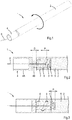
- FIG 1 shows a cartridge 1 for on- or offline cleaning installations, such as incinerators, heat exchangers, flue gas channels, and silos.
- the cartridge comprises a casing, in this example, a cylindrical sleeve 2 closed at one end and open at the other end, a detonator 3 that is accommodated in a housing 4, which housing in turn is mounted in the open end of the sleeve, such that it is movable between a first (safe) position, shown in cross-section in Figure 2 , wherein the detonator is isolated from the pyrotechnical mixture 5 inside the sleeve, and a second (primed) position, shown in cross-section in Figure 3 , wherein the detonator extends directly in the pyrotechnical mixture.
- a first (safe) position shown in cross-section in Figure 2
- a second (primed) position shown in cross-section in Figure 3 , wherein the detonator extends directly in the pyrotechnical mixture.
- the open end of the sleeve 2 is provided with an internal groove 6, in this this example an internal screw thread that defined in an insert 7, shown in more detail in Figures 5A and 5B , that is fixed, e.g. clamped, welded, or glued, in the open end of the sleeve.
- the housing 4 accommodating the detonator 3 has a first section 4A, that has the same cylindrical shape and the same diameter as the sleeve 2 and from which section the wires 8 of the detonator 3 extend, and a second section 4B that carries at least one protrusion, e.g. two projections 9, or an external screw thread.
- the (distal) end of the second section 4B contains the actual detonator 3 and comprises a plurality of openings 10 and a disc-shaped front wall 11 having a diameter that is equal to the internal diameter on the insert 7.
- the detonator 3 when the housing 4 is in the first (safe) position, the detonator 3 is in a closed chamber defined by the inner wall of the insert 7 and the front wall 11 of the housing 4 and, when the housing 4 has been moved to the second (primed) position, the detonator 3 is, via the openings, in direct contact with the pyrotechnical mixture 5 of at least communicates directly with the cavity in the sleeve 2 containing the mixture 5.
- the angle between the safe and primed positions of the housing and the detonator is defined by the pitch, P, of the internal screw thread and the distance, D, between the (proximal) end of the sleeve and the (distal) end of the first section 4A of the housing 4.
- the pitch, P, of the internal thread is twice the distance, D, the housing must be turned over an angle of 180 degrees to prime that cartridge and lock, by friction, the housing and the detonator with respect to the sleeve.
- a blocking mechanism such as a ring (not shown) that can be torn off e.g. by breaking it, is placed in the space provided by the distance, D, to prevent inadvertent priming.
- the casing, housing, and insert were made from an thermoplastic material. Suitable manufacturing methods include injection moulding, extrusion, and 3D printing.
- the cartridge of the present invention can be primed at the work, e.g. some moments prior to its use, efficiently and by a straightforward act.
Landscapes
- Engineering & Computer Science (AREA)
- General Engineering & Computer Science (AREA)
- Chemical & Material Sciences (AREA)
- Combustion & Propulsion (AREA)
- Mechanical Engineering (AREA)
- Feeding, Discharge, Calcimining, Fusing, And Gas-Generation Devices (AREA)
- Cleaning In General (AREA)
- Air Bags (AREA)
Abstract

Description
- The invention relates to a cartridge for on- or offline cleaning installations, such as incinerators, heat exchangers, flue gas channels, and silos, comprising a casing, e.g. a sleeve, containing a pyrotechnical mixture, in particular a class P2 pyrotechnical mixture, and/or components of a pyrotechnical mixture and comprising an electrical detonator for initiating deflagration of the mixture. Other applications include, but are not limited to, bundles of heat exchanger pipes, evaporators, economizers, washers/scrubbers, cyclones, catalysts, absorbers, spray dryers, cooling towers, funnels, and various filters.
- The invention also relates to a system comprising such a cartridge and a lance for holding, cooling, and positioning the cartridge inside an installation.
-
WO 2011/096872 relates to a rock cracker cartridge (numeral 1 in the figures ofWO 2011/096872 ) which contains a cracking powder charge (6) and an ignition capsule (30) with an ignition powder charge (29) in an ignition unit sleeve (31) which does not possess the mechanical strength that would be required for the ignition powder charge to be exploded in the open air when ignited. In the rock cracker cartridge there is also provided an ignition assembly sleeve (7a) which surrounds the ignition unit sleeve when the rock cracker cartridge is primed. In combination, the assembly which surrounds the cracking powder charge, and which comprises the ignition unit sleeve and the ignition assembly sleeve, has a sufficient strength for an adequate pressure to be developed in the assembly such that the ignition powder charge will explode and generate a flame of fire and the ignition unit sleeve as well as the ignition assembly sleeve be penetrated by the pressure and the flame of fire, said flame of fire igniting the cracking powder charge. -
DE 20 2017 001549 relates to a system for deslagging containers and plants by means of blasting, wherein a classified as a so-called firecrackers / pyrotechnics, disintegrants (z. B. class IV, T1 or T2), in the vicinity of the pollution or Caking or slagging is brought, and the explosive mixture is made to explode. - Although pyrotechnics are by some perceived as relatively safe when compared to gelatinous explosives, such as ethylene glycol dinitrate, diethylene glycol dinitrate, nitro-glycerine, in practice they are not safer.
- It is an object of the present invention to provide an improved cartridge for cleaning installations by means of pyrotechnics.
- To this end, the cartridge according to the present invention is characterized by a housing which accommodates the detonator and which housing is attached to the casing and movable between a first (safe) position, wherein the detonator is isolated from the pyrotechnical mixture, and a second (primed) position, wherein the detonator extends in the pyrotechnical mixture.
- In an embodiment, the housing or detonator on the one hand and the casing on the other hand comprise engaging parts that enable moving, and preferably also locking after priming, of the detonator to inside the mixture by relative sliding and/or rotation of the detonator and the casing.
- In a refinement, the housing or detonator on the one hand comprises at least one protrusion, such as a cam, key, or external screw thread, or a groove, such as an bayonet slot or an internal screw thread, and the casing on the other hand comprises a groove or protrusion, respectively, cooperating with the protrusion or groove in or on the housing to define a path of the relative movement.
- Thus, the cartridge can be primed at the work, e.g. some moments prior to its use, by establishing e.g. a screw, bayonet, or snap fit connection between the detonator and the casing.
- In an embodiment, a blocking mechanism, such as a ring that can be torn off e.g. by breaking it, is located between the housing and the casing, to prevent inadvertent priming.
- In an embodiment, the donator is at the distal end of the housing and exposed at least laterally.
- In another embodiment, the mixture is a suspended, e.g. fluidized (upon shaking) powder, i.e. a powder loose in the casing, a compactable powder, i.e. a coherent mass which can still be compacted to such an extent that it allows the detonator to be extended directly into the mixture, or a compacted powder with a defined cavity for receiving the detonator.
- The invention also relates to a cartridge comprising a casing containing a pyrotechnical mixture and/or components of a pyrotechnical mixture and comprising an electrical detonator for initiating deflagration of the mixture, wherein the detonator is configured to initiate deflagration of the mixture at a current of at least five Ampere, preferably at least ten Ampere, preferably at least twenty Ampere.
- The Meta-pyro pyrotechnical igniter mentioned in
WO 2011/096872 has a firing current of max 2,12 A, see http://www.meta-pyro.cz/en/technical-specifications. By providing, in accordance with the present invention a detonator having a firing current of at least 5 A, the risk of accidental detonation resulting from sparks or static electricity, occurring e.g. during transport or at a work, is reduced. - In an embodiment, to shield it from static electricity and/or moist, in the first position of the housing, the detonator is enclosed or encapsulated by a synthetic material, such as a thermoplastic polymer.
- In a refinement the casing is made of or laminated with a synthetic material. In another embodiment, the casing is water- and/or dust tight.
- This will increase safety in that contamination of the work with pyrotechnical mixture leaking from the cartridge is avoided or at least reduced and in that the risk a dud cartridge, e.g. a misfire, is reduced.
- In an embodiment, the casing is enveloped by a thermally insulating material and/or a liquid absorbing material.
- Thus, the cartridge is for, e.g. a few minutes, protected from heat and/or cooled by a coolant, such as water soaking the liquid absorbing material.
- The invention also relates to a cartridge comprising a casing containing a pyrotechnical mixture and/or components of a pyrotechnical mixture and comprising an electrical detonator for initiating deflagration of the mixture, comprising a plurality of compartments and wherein the compartments contain different components of the pyrotechnical mixture.
- This allows mixing of these components, e.g. by removing or breaking the wall(s) between the compartments and shaking the cartridge, a short time before its use, thus further increasing safety, in particular during transport.
- In an embodiment, the nett mass (NEM) of the mixture is in a range from 20 to 1000 grams, preferably in a range from 20 to 500 grams.
- The nett mass of the mixture and the dimensions and shape of the cartridge determine to some extend the speed of the deflagration and the size and shape of the shock wave. E.g. a smaller nett mass will typically result in a higher deflagration speed and a shock wave of relatively small dimensions, providing a fierce and localized blow.
- In another embodiment, the mixture is in accordance with class P2 of directive 2007/23/EC of the European Parliament and of the Council of 23 May 2007 on the placing on the market of pyrotechnic articles. The mixture may for example comprise a reducing agent or fuel, such as black powder, aluminum, boron, titanium and/or magnesium; and an oxidant such as sodium nitrate, potassium chlorate and/or potassium perchlorate. Preferred examples of pyrotechnical mixtures include black powder, aluminum and potassium perchlorate.
- In an embodiment, the detonator is a wireless detonator configured to initiated deflagration upon receiving an encrypted radio signal.
- In another embodiment, the cartridge is coupled to a controller by a set of wires, which controller is configured to continually measure electrical resistance of the wires and the detonator.
- Thus, it is possible to continually monitor the condition of the system and reduce the risk of a misfire.
- The invention also relates to a system for on- or offline cleaning installations, such as incinerators, heat exchangers, flue gas channels, and silos, comprising a cartridge according to any one of the preceding claims, a lance, which is provided at its proximal end, i.e. the end (to be) held by and thus close to an operator, a supply for a coolant, such as water or a mixture of air and water, and a connector and/or electrical wires to connect the detonator to a controller and which is provided at its distal end, i.e. the end far or farthest from the operator, with a head for holding the cartridge and provided with outlets, e.g. nozzles, or ducts for supplying coolant to or about the cartridge.
- In an example, the wires of the detonator are connected to the wires in the lance, the cartridge is primed and the cartridge is fixed in the head of the lance. Next, the coolant supply is turned on and the cartridge is inserted, by means of the lance, through an opening, such as a manhole, in an online installation and positioned adjacent a surface or element, such as a bundle of heat exchanger pipes, to be cleaned. A spray or mist of coolant surrounds the cartridge to prevent it from untimely deflagration. When at the desired location, the detonator is activated and the mixture deflagrates, thus cleaning the adjacent surface or element.
-
EP 1 275 925 -
EP 1 067 349 - Handbuch Sprengtechnik, VEB Deutscher Verlag fur Grundstoffindustrie, Leipzig 1975, pages 344-351 discloses the cooling of explosive charges.
-
US 5,494,004 relates to an online pulsed detonation/deflagration soot blower. - The invention will now be explained in more detail with reference to the drawings, which show a preferred embodiment of the present invention.
-
Figure 1 is a perspective of a cartridge according to the present invention comprising a detonator and containing a pyrotechnical mixture. -
Figure 2 is partial cross-section of the cartridge shown inFigure 1 with the detonator in a safe position. -
Figure 3 is partial cross-section of the cartridge shown inFigure 1 with the detonator in the primed position. -
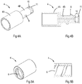
Figure 4A and 4B show the housing of the detonator. -
Figures 5A and 5B show an insert for rotatably receiving the housing of the detonator. -
Figure 1 shows acartridge 1 for on- or offline cleaning installations, such as incinerators, heat exchangers, flue gas channels, and silos. The cartridge comprises a casing, in this example, acylindrical sleeve 2 closed at one end and open at the other end, adetonator 3 that is accommodated in ahousing 4, which housing in turn is mounted in the open end of the sleeve, such that it is movable between a first (safe) position, shown in cross-section inFigure 2 , wherein the detonator is isolated from thepyrotechnical mixture 5 inside the sleeve, and a second (primed) position, shown in cross-section inFigure 3 , wherein the detonator extends directly in the pyrotechnical mixture. - The open end of the
sleeve 2 is provided with aninternal groove 6, in this this example an internal screw thread that defined in aninsert 7, shown in more detail inFigures 5A and 5B , that is fixed, e.g. clamped, welded, or glued, in the open end of the sleeve. - The
housing 4 accommodating thedetonator 3 has afirst section 4A, that has the same cylindrical shape and the same diameter as thesleeve 2 and from which section thewires 8 of thedetonator 3 extend, and asecond section 4B that carries at least one protrusion, e.g. twoprojections 9, or an external screw thread. - The (distal) end of the
second section 4B contains theactual detonator 3 and comprises a plurality ofopenings 10 and a disc-shapedfront wall 11 having a diameter that is equal to the internal diameter on theinsert 7. Thus, when thehousing 4 is in the first (safe) position, thedetonator 3 is in a closed chamber defined by the inner wall of theinsert 7 and thefront wall 11 of thehousing 4 and, when thehousing 4 has been moved to the second (primed) position, thedetonator 3 is, via the openings, in direct contact with thepyrotechnical mixture 5 of at least communicates directly with the cavity in thesleeve 2 containing themixture 5. - In this example, the angle between the safe and primed positions of the housing and the detonator is defined by the pitch, P, of the internal screw thread and the distance, D, between the (proximal) end of the sleeve and the (distal) end of the
first section 4A of thehousing 4. If the pitch, P, of the internal thread is twice the distance, D, the housing must be turned over an angle of 180 degrees to prime that cartridge and lock, by friction, the housing and the detonator with respect to the sleeve. In an embodiment, a blocking mechanism, such as a ring (not shown) that can be torn off e.g. by breaking it, is placed in the space provided by the distance, D, to prevent inadvertent priming. - The casing, housing, and insert were made from an thermoplastic material. Suitable manufacturing methods include injection moulding, extrusion, and 3D printing.
- The cartridge of the present invention can be primed at the work, e.g. some moments prior to its use, efficiently and by a straightforward act.
- The invention is not restricted to the above-described embodiments, which can be varied in a number of ways within the scope of the claims.
Claims (15)
- Cartridge (1) for cleaning installations, such as incinerators, heat exchangers, flue gas channels, and silos, comprising a casing, e.g. a sleeve (2), containing a pyrotechnical mixture (5) and/or components of a pyrotechnical mixture and comprising an electrical detonator (3) for initiating deflagration of the mixture, characterized by a housing (4) which accommodates the detonator (3) and which housing (4) is attached to the casing (3) and movable between a first position, wherein the detonator (3) is isolated from the pyrotechnical mixture (5), and a second position, wherein the detonator (3) extends in the pyrotechnical mixture (5).
- Cartridge (1) according to claim 1, wherein the housing (4) or detonator (3) on the one hand and the casing (2) on the other hand comprise engaging parts (9; 6) that enable moving of the detonator (3) to inside the mixture (5) by relative sliding and/or rotation of the detonator (3) and the casing (2).
- Cartridge (1) according to claim 1 or 2, wherein the housing (4) or detonator (2) on the one hand comprises at least one protrusion (9) or a groove and the casing (2) on the other hand comprises a groove (6) or protrusion, respectively.
- Cartridge (1) according to any one of the preceding claims, wherein the donator (3) is located at or near the distal end of the housing (4) and exposed at least laterally.
- Cartridge (1) according to any one of the preceding claims, wherein the mixture (5) is a suspended powder, a compactable powder, or a compacted powder with a defined cavity for receiving the detonator (3).
- Cartridge (1) according to any one of the preceding claims or the pre-amble of claim 1, wherein the detonator (3) is configured to initiate deflagration at a current of at least five Ampere, preferably at least ten Ampere, preferably at least twenty Ampere.
- Cartridge (1) according to any one of the preceding claims, wherein, in the first position of the housing (4), the detonator (3) is enclosed or encapsulated by a synthetic material, such as a thermoplastic polymer.
- Cartridge (1) according to any one of the preceding claims, wherein the casing (2) and/or the housing (4) is made of or laminated with a synthetic material.
- Cartridge (1) according to any one of the preceding claims, wherein the casing (2) is water- and/or dust tight.
- Cartridge (1) according to any one of the preceding claims, wherein the casing (2) is enveloped by a thermally insulating material and/or a liquid absorbing material.
- Cartridge (1) according to any one of the preceding claims or the pre-amble of claim 1, comprising a plurality of compartments and wherein the compartments contain different components of the pyrotechnical mixture (5) .
- Cartridge (1) according to any one of the preceding claims, wherein the nett mass (NEM) of the mixture is in a range from 20 to 1000 grams.
- Cartridge (1) according to any one of the preceding claims, wherein the mixture (5) comprises a reducing agent or fuel, such as black powder, aluminum, boron, titanium and/or magnesium; and an oxidant such as sodium nitrate, potassium chlorate and/or potassium perchlorate.
- Cartridge (1) according to any one of the preceding claims, that is coupled to a controller by a set of wires (8), which controller is configured to continually measure electrical resistance of the wires (8) and the detonator (3).
- System for cleaning installations, such as incinerators, heat exchangers, flue gas channels, and silos, comprising a cartridge (1) according to any one of the preceding claims, a lance, which is provided at its proximal end with a supply for a coolant and a connector and/or electrical wires to connect the detonator to a controller and which is provided at its distal end with a head for holding the cartridge and provided with outlets or ducts for supplying coolant to or about the cartridge (1).
Priority Applications (5)
| Application Number | Priority Date | Filing Date | Title |
|---|---|---|---|
| EP19187636.6A EP3770545A1 (en) | 2019-07-22 | 2019-07-22 | Device for and method of cleaning installations |
| EP20746599.8A EP4004484A2 (en) | 2019-07-22 | 2020-07-22 | Device for and method of cleaning installations |
| AU2020318762A AU2020318762A1 (en) | 2019-07-22 | 2020-07-22 | Device for and method of cleaning installations |
| JP2022504018A JP2022541598A (en) | 2019-07-22 | 2020-07-22 | Device for cleaning equipment and method for cleaning equipment |
| PCT/EP2020/070728 WO2021013905A2 (en) | 2019-07-22 | 2020-07-22 | Device for and method of cleaning installations |
Applications Claiming Priority (1)
| Application Number | Priority Date | Filing Date | Title |
|---|---|---|---|
| EP19187636.6A EP3770545A1 (en) | 2019-07-22 | 2019-07-22 | Device for and method of cleaning installations |
Publications (1)
| Publication Number | Publication Date |
|---|---|
| EP3770545A1 true EP3770545A1 (en) | 2021-01-27 |
Family
ID=67438459
Family Applications (2)
| Application Number | Title | Priority Date | Filing Date |
|---|---|---|---|
| EP19187636.6A Pending EP3770545A1 (en) | 2019-07-22 | 2019-07-22 | Device for and method of cleaning installations |
| EP20746599.8A Pending EP4004484A2 (en) | 2019-07-22 | 2020-07-22 | Device for and method of cleaning installations |
Family Applications After (1)
| Application Number | Title | Priority Date | Filing Date |
|---|---|---|---|
| EP20746599.8A Pending EP4004484A2 (en) | 2019-07-22 | 2020-07-22 | Device for and method of cleaning installations |
Country Status (4)
| Country | Link |
|---|---|
| EP (2) | EP3770545A1 (en) |
| JP (1) | JP2022541598A (en) |
| AU (1) | AU2020318762A1 (en) |
| WO (1) | WO2021013905A2 (en) |
Families Citing this family (1)
| Publication number | Priority date | Publication date | Assignee | Title |
|---|---|---|---|---|
| TWI751919B (en) * | 2021-02-26 | 2022-01-01 | 印能科技股份有限公司 | Contact type electric rail overhead transport vehicle (OHT) dust collection system |
Citations (9)
| Publication number | Priority date | Publication date | Assignee | Title |
|---|---|---|---|---|
| FR2445186A1 (en) * | 1978-12-29 | 1980-07-25 | Magyar Aluminium | Explosive deposit removal in chemical appts. deposit - uses metered quantities of explosive inserted into deposit |
| US4920852A (en) * | 1988-05-10 | 1990-05-01 | Ireco Incorporated | Portable, self-contained explosives system |
| US5494004A (en) | 1994-09-23 | 1996-02-27 | Lockheed Corporation | On line pulsed detonation/deflagration soot blower |
| EP1067349A2 (en) | 1997-01-17 | 2001-01-10 | Francis Zilka | Device, system and method for on-line explosive deslagging |
| EP1275925A1 (en) | 2001-07-09 | 2003-01-15 | Hans Eichner GmbH & Co.KG | Method and apparatus for destroying locally compact materials in hot thermal installations |
| US20060124019A1 (en) * | 2004-12-14 | 2006-06-15 | Plexus Scientific Corporation | Conduit-clearing pyrotechnic device for remediation of residual explosive contamination |
| WO2011096872A1 (en) | 2010-02-03 | 2011-08-11 | Bengtsson Jan-Aake | Rock cracker cartridge and ignition capsule |
| FR2971583A1 (en) * | 2011-02-14 | 2012-08-17 | Astrium Sas | METHOD FOR DESTRUCTION OF EXPLOSION EXPLOSIVE WASTE AND CORRESPONDING DETONATION SYSTEM |
| DE202017001549U1 (en) | 2017-03-23 | 2018-06-28 | Volker Kruse | System for cleaning incinerators by blasting in hot masses |
Family Cites Families (9)
| Publication number | Priority date | Publication date | Assignee | Title |
|---|---|---|---|---|
| JPS5221046B2 (en) * | 1971-11-16 | 1977-06-08 | ||
| JPS5677782A (en) * | 1979-11-29 | 1981-06-26 | Nissan Motor Co Ltd | Pyrotechnic time limiting device |
| JP2832500B2 (en) * | 1992-12-02 | 1998-12-09 | 和彦 熱田 | Bench blasting method |
| JPH1054697A (en) * | 1996-08-14 | 1998-02-24 | Tadao Yoshida | Energy substance processing structure |
| JPH10288499A (en) * | 1997-04-10 | 1998-10-27 | Asahi Chem Ind Co Ltd | Continuous portfire for electric detonator |
| JP3051439U (en) * | 1997-10-14 | 1998-08-25 | 日興技化株式会社 | Ignition device with static resistance |
| JP4122990B2 (en) * | 2003-01-31 | 2008-07-23 | 日油株式会社 | Water-containing explosive container, water-containing explosive container, and method for discharging water-containing explosive |
| JP5221856B2 (en) * | 2006-07-06 | 2013-06-26 | 日興技化株式会社 | Loading method of crushing cartridge |
| WO2017145064A1 (en) * | 2016-02-24 | 2017-08-31 | Fowlds 3 Limited | Cartridge with a displaceable initiator |
-
2019
- 2019-07-22 EP EP19187636.6A patent/EP3770545A1/en active Pending
-
2020
- 2020-07-22 AU AU2020318762A patent/AU2020318762A1/en active Pending
- 2020-07-22 EP EP20746599.8A patent/EP4004484A2/en active Pending
- 2020-07-22 JP JP2022504018A patent/JP2022541598A/en active Pending
- 2020-07-22 WO PCT/EP2020/070728 patent/WO2021013905A2/en active Application Filing
Patent Citations (9)
| Publication number | Priority date | Publication date | Assignee | Title |
|---|---|---|---|---|
| FR2445186A1 (en) * | 1978-12-29 | 1980-07-25 | Magyar Aluminium | Explosive deposit removal in chemical appts. deposit - uses metered quantities of explosive inserted into deposit |
| US4920852A (en) * | 1988-05-10 | 1990-05-01 | Ireco Incorporated | Portable, self-contained explosives system |
| US5494004A (en) | 1994-09-23 | 1996-02-27 | Lockheed Corporation | On line pulsed detonation/deflagration soot blower |
| EP1067349A2 (en) | 1997-01-17 | 2001-01-10 | Francis Zilka | Device, system and method for on-line explosive deslagging |
| EP1275925A1 (en) | 2001-07-09 | 2003-01-15 | Hans Eichner GmbH & Co.KG | Method and apparatus for destroying locally compact materials in hot thermal installations |
| US20060124019A1 (en) * | 2004-12-14 | 2006-06-15 | Plexus Scientific Corporation | Conduit-clearing pyrotechnic device for remediation of residual explosive contamination |
| WO2011096872A1 (en) | 2010-02-03 | 2011-08-11 | Bengtsson Jan-Aake | Rock cracker cartridge and ignition capsule |
| FR2971583A1 (en) * | 2011-02-14 | 2012-08-17 | Astrium Sas | METHOD FOR DESTRUCTION OF EXPLOSION EXPLOSIVE WASTE AND CORRESPONDING DETONATION SYSTEM |
| DE202017001549U1 (en) | 2017-03-23 | 2018-06-28 | Volker Kruse | System for cleaning incinerators by blasting in hot masses |
Non-Patent Citations (1)
| Title |
|---|
| "Handbuch Sprengtechnik", 1975, VEB DEUTSCHER VERLAG FUR GRUNDSTOFFINDUSTRIE, pages: 344 - 351 |
Also Published As
| Publication number | Publication date |
|---|---|
| JP2022541598A (en) | 2022-09-26 |
| WO2021013905A2 (en) | 2021-01-28 |
| AU2020318762A1 (en) | 2022-02-17 |
| EP4004484A2 (en) | 2022-06-01 |
| WO2021013905A3 (en) | 2021-03-04 |
Similar Documents
| Publication | Publication Date | Title |
|---|---|---|
| EP1476712B1 (en) | Device for the disruption of explosive ordnance | |
| CN203719554U (en) | Ammunition destroying device | |
| KR870008166A (en) | Portable firearms and shotguns | |
| EP3770545A1 (en) | Device for and method of cleaning installations | |
| US8178744B1 (en) | Method and apparatus to demilitarize small caliber ammunition | |
| US9366517B2 (en) | Method and apparatus to demilitarize munition energetics | |
| US5052302A (en) | Unpressurized combustible primer for cannon cartridges | |
| EP0600039A1 (en) | Insensitive propellant ignitor | |
| EP3885686A1 (en) | Method of and charge for cleaning incinerator heat exchangers | |
| US5907121A (en) | Blank cartridge for firearms | |
| US4697524A (en) | After-firing safety | |
| US4286431A (en) | Ignition system for combustible gases or liquids | |
| FI86108B (en) | Ball-shot cartridge with explosive projectile | |
| GB1605165A (en) | Arrangement for firing a round of amunition by means of a liquid propellant | |
| WO2018029248A1 (en) | A method of and a cartridge for disarming an unexploded blasting charge in a drill hole | |
| US1299869A (en) | Gun-destroying means. | |
| RU2714165C1 (en) | Ammunition reloading method | |
| RU2642570C1 (en) | Igniter | |
| WO2021240414A1 (en) | Method and apparatus for hot or cold cleaning combustion slag by means of an explosive shock wave | |
| US5964586A (en) | Method, apparatus, and ignition device for ignition of inflammable gases from a flare on a flame tower | |
| US11976908B2 (en) | Flexible metal/metal oxide and/or intermetallic reactant ribbon cutting system | |
| RU2192610C2 (en) | Separate-loading round | |
| JP7415512B2 (en) | Ignition system for end-fired rocket motors | |
| RU2234050C1 (en) | Nose fuse | |
| RU2095721C1 (en) | Weapon using liquid propellant |
Legal Events
| Date | Code | Title | Description |
|---|---|---|---|
| PUAI | Public reference made under article 153(3) epc to a published international application that has entered the european phase |
Free format text: ORIGINAL CODE: 0009012 |
|
| STAA | Information on the status of an ep patent application or granted ep patent |
Free format text: STATUS: THE APPLICATION HAS BEEN PUBLISHED |
|
| AK | Designated contracting states |
Kind code of ref document: A1 Designated state(s): AL AT BE BG CH CY CZ DE DK EE ES FI FR GB GR HR HU IE IS IT LI LT LU LV MC MK MT NL NO PL PT RO RS SE SI SK SM TR |
|
| AX | Request for extension of the european patent |
Extension state: BA ME |
|
| STAA | Information on the status of an ep patent application or granted ep patent |
Free format text: STATUS: REQUEST FOR EXAMINATION WAS MADE |
|
| 17P | Request for examination filed |
Effective date: 20210727 |
|
| RBV | Designated contracting states (corrected) |
Designated state(s): AL AT BE BG CH CY CZ DE DK EE ES FI FR GB GR HR HU IE IS IT LI LT LU LV MC MK MT NL NO PL PT RO RS SE SI SK SM TR |
|
| GRAP | Despatch of communication of intention to grant a patent |
Free format text: ORIGINAL CODE: EPIDOSNIGR1 |
|
| STAA | Information on the status of an ep patent application or granted ep patent |
Free format text: STATUS: GRANT OF PATENT IS INTENDED |
|
| INTG | Intention to grant announced |
Effective date: 20231218 |
|
| GRAS | Grant fee paid |
Free format text: ORIGINAL CODE: EPIDOSNIGR3 |
|
| GRAA | (expected) grant |
Free format text: ORIGINAL CODE: 0009210 |
|
| STAA | Information on the status of an ep patent application or granted ep patent |
Free format text: STATUS: THE PATENT HAS BEEN GRANTED |