EP3767732A1 - Rechargeable battery - Google Patents
Rechargeable battery Download PDFInfo
- Publication number
- EP3767732A1 EP3767732A1 EP20185948.5A EP20185948A EP3767732A1 EP 3767732 A1 EP3767732 A1 EP 3767732A1 EP 20185948 A EP20185948 A EP 20185948A EP 3767732 A1 EP3767732 A1 EP 3767732A1
- Authority
- EP
- European Patent Office
- Prior art keywords
- battery pack
- cell carrier
- cell
- battery
- receiving space
- Prior art date
- Legal status (The legal status is an assumption and is not a legal conclusion. Google has not performed a legal analysis and makes no representation as to the accuracy of the status listed.)
- Granted
Links
- 150000001875 compounds Chemical class 0.000 claims abstract description 88
- 238000004382 potting Methods 0.000 claims abstract description 85
- 238000001816 cooling Methods 0.000 claims abstract description 60
- 238000009423 ventilation Methods 0.000 claims abstract description 13
- 238000007789 sealing Methods 0.000 claims description 55
- 239000000463 material Substances 0.000 claims description 12
- 238000013016 damping Methods 0.000 claims description 10
- 229920001971 elastomer Polymers 0.000 claims description 9
- 229920003023 plastic Polymers 0.000 claims description 7
- 239000004033 plastic Substances 0.000 claims description 7
- 239000013013 elastic material Substances 0.000 claims description 5
- 238000000926 separation method Methods 0.000 claims description 4
- 239000005871 repellent Substances 0.000 claims description 3
- 239000013536 elastomeric material Substances 0.000 claims description 2
- 239000004020 conductor Substances 0.000 description 34
- 239000002184 metal Substances 0.000 description 21
- 239000000243 solution Substances 0.000 description 20
- 238000013461 design Methods 0.000 description 16
- 238000004519 manufacturing process Methods 0.000 description 13
- 238000005538 encapsulation Methods 0.000 description 9
- 230000035515 penetration Effects 0.000 description 7
- XLYOFNOQVPJJNP-UHFFFAOYSA-N water Substances O XLYOFNOQVPJJNP-UHFFFAOYSA-N 0.000 description 7
- 239000000428 dust Substances 0.000 description 6
- 230000017525 heat dissipation Effects 0.000 description 6
- 238000005266 casting Methods 0.000 description 5
- 230000006378 damage Effects 0.000 description 5
- 230000000694 effects Effects 0.000 description 5
- 229910001416 lithium ion Inorganic materials 0.000 description 5
- 238000000034 method Methods 0.000 description 5
- HBBGRARXTFLTSG-UHFFFAOYSA-N Lithium ion Chemical compound [Li+] HBBGRARXTFLTSG-UHFFFAOYSA-N 0.000 description 4
- 238000007599 discharging Methods 0.000 description 4
- 230000007613 environmental effect Effects 0.000 description 4
- 230000008569 process Effects 0.000 description 4
- 239000011248 coating agent Substances 0.000 description 3
- 238000000576 coating method Methods 0.000 description 3
- 230000007797 corrosion Effects 0.000 description 3
- 238000005260 corrosion Methods 0.000 description 3
- 239000000806 elastomer Substances 0.000 description 3
- 238000013021 overheating Methods 0.000 description 3
- 239000011347 resin Substances 0.000 description 3
- 229920005989 resin Polymers 0.000 description 3
- 238000005516 engineering process Methods 0.000 description 2
- 238000004880 explosion Methods 0.000 description 2
- 229920001821 foam rubber Polymers 0.000 description 2
- 238000002347 injection Methods 0.000 description 2
- 239000007924 injection Substances 0.000 description 2
- 239000007788 liquid Substances 0.000 description 2
- 239000012528 membrane Substances 0.000 description 2
- 238000010943 off-gassing Methods 0.000 description 2
- 230000000149 penetrating effect Effects 0.000 description 2
- 229920001296 polysiloxane Polymers 0.000 description 2
- 238000003825 pressing Methods 0.000 description 2
- 230000035939 shock Effects 0.000 description 2
- 238000012546 transfer Methods 0.000 description 2
- WZZBNLYBHUDSHF-DHLKQENFSA-N 1-[(3s,4s)-4-[8-(2-chloro-4-pyrimidin-2-yloxyphenyl)-7-fluoro-2-methylimidazo[4,5-c]quinolin-1-yl]-3-fluoropiperidin-1-yl]-2-hydroxyethanone Chemical compound CC1=NC2=CN=C3C=C(F)C(C=4C(=CC(OC=5N=CC=CN=5)=CC=4)Cl)=CC3=C2N1[C@H]1CCN(C(=O)CO)C[C@@H]1F WZZBNLYBHUDSHF-DHLKQENFSA-N 0.000 description 1
- RNFJDJUURJAICM-UHFFFAOYSA-N 2,2,4,4,6,6-hexaphenoxy-1,3,5-triaza-2$l^{5},4$l^{5},6$l^{5}-triphosphacyclohexa-1,3,5-triene Chemical compound N=1P(OC=2C=CC=CC=2)(OC=2C=CC=CC=2)=NP(OC=2C=CC=CC=2)(OC=2C=CC=CC=2)=NP=1(OC=1C=CC=CC=1)OC1=CC=CC=C1 RNFJDJUURJAICM-UHFFFAOYSA-N 0.000 description 1
- 208000027418 Wounds and injury Diseases 0.000 description 1
- 238000010521 absorption reaction Methods 0.000 description 1
- 238000009825 accumulation Methods 0.000 description 1
- 230000032683 aging Effects 0.000 description 1
- 238000010276 construction Methods 0.000 description 1
- 238000013270 controlled release Methods 0.000 description 1
- 230000008878 coupling Effects 0.000 description 1
- 238000010168 coupling process Methods 0.000 description 1
- 238000005859 coupling reaction Methods 0.000 description 1
- 230000003111 delayed effect Effects 0.000 description 1
- 238000011161 development Methods 0.000 description 1
- 230000018109 developmental process Effects 0.000 description 1
- 238000009826 distribution Methods 0.000 description 1
- 239000003063 flame retardant Substances 0.000 description 1
- 229920002457 flexible plastic Polymers 0.000 description 1
- 238000007667 floating Methods 0.000 description 1
- 230000001771 impaired effect Effects 0.000 description 1
- 238000001746 injection moulding Methods 0.000 description 1
- 208000014674 injury Diseases 0.000 description 1
- 230000003993 interaction Effects 0.000 description 1
- 230000005923 long-lasting effect Effects 0.000 description 1
- 239000002923 metal particle Substances 0.000 description 1
- 238000012544 monitoring process Methods 0.000 description 1
- 239000012811 non-conductive material Substances 0.000 description 1
- 239000002245 particle Substances 0.000 description 1
- 229910000679 solder Inorganic materials 0.000 description 1
- 238000005476 soldering Methods 0.000 description 1
- -1 thermal conductivity Chemical class 0.000 description 1
Images


Classifications
-
- H—ELECTRICITY
- H01—ELECTRIC ELEMENTS
- H01M—PROCESSES OR MEANS, e.g. BATTERIES, FOR THE DIRECT CONVERSION OF CHEMICAL ENERGY INTO ELECTRICAL ENERGY
- H01M10/00—Secondary cells; Manufacture thereof
- H01M10/42—Methods or arrangements for servicing or maintenance of secondary cells or secondary half-cells
- H01M10/4207—Methods or arrangements for servicing or maintenance of secondary cells or secondary half-cells for several batteries or cells simultaneously or sequentially
-
- H—ELECTRICITY
- H01—ELECTRIC ELEMENTS
- H01M—PROCESSES OR MEANS, e.g. BATTERIES, FOR THE DIRECT CONVERSION OF CHEMICAL ENERGY INTO ELECTRICAL ENERGY
- H01M50/00—Constructional details or processes of manufacture of the non-active parts of electrochemical cells other than fuel cells, e.g. hybrid cells
- H01M50/20—Mountings; Secondary casings or frames; Racks, modules or packs; Suspension devices; Shock absorbers; Transport or carrying devices; Holders
- H01M50/247—Mountings; Secondary casings or frames; Racks, modules or packs; Suspension devices; Shock absorbers; Transport or carrying devices; Holders specially adapted for portable devices, e.g. mobile phones, computers, hand tools or pacemakers
-
- B—PERFORMING OPERATIONS; TRANSPORTING
- B25—HAND TOOLS; PORTABLE POWER-DRIVEN TOOLS; MANIPULATORS
- B25F—COMBINATION OR MULTI-PURPOSE TOOLS NOT OTHERWISE PROVIDED FOR; DETAILS OR COMPONENTS OF PORTABLE POWER-DRIVEN TOOLS NOT PARTICULARLY RELATED TO THE OPERATIONS PERFORMED AND NOT OTHERWISE PROVIDED FOR
- B25F5/00—Details or components of portable power-driven tools not particularly related to the operations performed and not otherwise provided for
- B25F5/008—Cooling means
-
- H—ELECTRICITY
- H01—ELECTRIC ELEMENTS
- H01M—PROCESSES OR MEANS, e.g. BATTERIES, FOR THE DIRECT CONVERSION OF CHEMICAL ENERGY INTO ELECTRICAL ENERGY
- H01M10/00—Secondary cells; Manufacture thereof
- H01M10/42—Methods or arrangements for servicing or maintenance of secondary cells or secondary half-cells
- H01M10/425—Structural combination with electronic components, e.g. electronic circuits integrated to the outside of the casing
-
- H—ELECTRICITY
- H01—ELECTRIC ELEMENTS
- H01M—PROCESSES OR MEANS, e.g. BATTERIES, FOR THE DIRECT CONVERSION OF CHEMICAL ENERGY INTO ELECTRICAL ENERGY
- H01M50/00—Constructional details or processes of manufacture of the non-active parts of electrochemical cells other than fuel cells, e.g. hybrid cells
- H01M50/20—Mountings; Secondary casings or frames; Racks, modules or packs; Suspension devices; Shock absorbers; Transport or carrying devices; Holders
- H01M50/204—Racks, modules or packs for multiple batteries or multiple cells
- H01M50/207—Racks, modules or packs for multiple batteries or multiple cells characterised by their shape
- H01M50/213—Racks, modules or packs for multiple batteries or multiple cells characterised by their shape adapted for cells having curved cross-section, e.g. round or elliptic
-
- H—ELECTRICITY
- H01—ELECTRIC ELEMENTS
- H01M—PROCESSES OR MEANS, e.g. BATTERIES, FOR THE DIRECT CONVERSION OF CHEMICAL ENERGY INTO ELECTRICAL ENERGY
- H01M50/00—Constructional details or processes of manufacture of the non-active parts of electrochemical cells other than fuel cells, e.g. hybrid cells
- H01M50/20—Mountings; Secondary casings or frames; Racks, modules or packs; Suspension devices; Shock absorbers; Transport or carrying devices; Holders
- H01M50/233—Mountings; Secondary casings or frames; Racks, modules or packs; Suspension devices; Shock absorbers; Transport or carrying devices; Holders characterised by physical properties of casings or racks, e.g. dimensions
- H01M50/24—Mountings; Secondary casings or frames; Racks, modules or packs; Suspension devices; Shock absorbers; Transport or carrying devices; Holders characterised by physical properties of casings or racks, e.g. dimensions adapted for protecting batteries from their environment, e.g. from corrosion
-
- H—ELECTRICITY
- H01—ELECTRIC ELEMENTS
- H01M—PROCESSES OR MEANS, e.g. BATTERIES, FOR THE DIRECT CONVERSION OF CHEMICAL ENERGY INTO ELECTRICAL ENERGY
- H01M2220/00—Batteries for particular applications
- H01M2220/30—Batteries in portable systems, e.g. mobile phone, laptop
-
- H—ELECTRICITY
- H01—ELECTRIC ELEMENTS
- H01M—PROCESSES OR MEANS, e.g. BATTERIES, FOR THE DIRECT CONVERSION OF CHEMICAL ENERGY INTO ELECTRICAL ENERGY
- H01M50/00—Constructional details or processes of manufacture of the non-active parts of electrochemical cells other than fuel cells, e.g. hybrid cells
- H01M50/20—Mountings; Secondary casings or frames; Racks, modules or packs; Suspension devices; Shock absorbers; Transport or carrying devices; Holders
- H01M50/271—Lids or covers for the racks or secondary casings
-
- Y—GENERAL TAGGING OF NEW TECHNOLOGICAL DEVELOPMENTS; GENERAL TAGGING OF CROSS-SECTIONAL TECHNOLOGIES SPANNING OVER SEVERAL SECTIONS OF THE IPC; TECHNICAL SUBJECTS COVERED BY FORMER USPC CROSS-REFERENCE ART COLLECTIONS [XRACs] AND DIGESTS
- Y02—TECHNOLOGIES OR APPLICATIONS FOR MITIGATION OR ADAPTATION AGAINST CLIMATE CHANGE
- Y02E—REDUCTION OF GREENHOUSE GAS [GHG] EMISSIONS, RELATED TO ENERGY GENERATION, TRANSMISSION OR DISTRIBUTION
- Y02E60/00—Enabling technologies; Technologies with a potential or indirect contribution to GHG emissions mitigation
- Y02E60/10—Energy storage using batteries
Definitions
- the present invention relates to a battery pack for a handheld power tool with at least one battery cell, a cell carrier for receiving and storing the at least one battery cell in sections in a receiving space of the cell carrier and a potting compound which, in the assembled state of the battery pack, creates spaces between the cell carrier and the at least one battery cell accommodated therein fills.
- Battery packs with one or more battery cells are known from the prior art in different sizes with a different number of cells connected in parallel and in series, as a result of which the capacity and voltage provided by the battery pack can be adapted to the respective application.
- the battery pack is particularly suitable for handheld power tools.
- the present invention can also be adapted to other uses and can be used, for example, in electrically operated motor vehicles or the like.
- the at least one battery cell can be designed as a lithium-ion battery cell or as a nickel-metal hybrid battery cell or the like. In the case of several battery cells, it is common practice to use battery cells of one cell type in one battery pack. However, it can also be useful for some applications to use battery cells of different cell types.
- the environmental influences occurring during operation such as. B. water and metal dust, if the battery pack is used in a handheld power tool, lead to short circuits or corrosion, so that the battery pack is damaged or even destroyed.
- a known task in connection with battery packs for handheld power tools is therefore to protect the battery cells in particular from such environmental influences.
- a cooling body is arranged on the underside of the handheld power tool battery pack, ie a body which can give off a particularly large amount of heat to the surroundings.
- This cooling body preferably has a surface area enlarged by cooling ribs.
- This additional heat sink is preferably formed at least essentially from a material with a high thermal conductivity, in particular a metal.
- the heat sink is arranged, for example, on one of the sides of the cell holder, so that the battery cells can give off heat to the heat sink particularly well via the cell holder.
- the battery cells are encapsulated with the potting compound, the potting compound having a low thermal resistance, e.g. B. a silicone-based potting compound.
- the potting compound fills gaps between the battery cells and the cell holder and thus enables particularly good heat transfer from the battery cells to the cell holder.
- penetration of moisture and / or liquids can be avoided by means of the potting compound, so that the components cast therein are protected from moisture. Corrosion, fault currents or short circuits can thus be reduced.
- an additional element is provided, namely in particular a metal heat sink, which in turn leads to an increase in the weight of the battery pack.
- a battery pack with a housing that has a first housing part and at least one second housing part, wherein the housing parts are connected to one another in a waterproof and / or dust-tight manner, with a plurality of cavities for receiving cells in the first housing part and with an interface on the second housing part which is designed for mechanical and electrical coupling with an external device.
- the housing has a plurality of heat conducting elements for passive cooling on an outer surface of the housing, the first housing part with the cavities being formed in one piece together with the heat conducting elements from a thermally conductive plastic.
- a display and actuation field is formed on the housing and is covered with a flexible film so that it is completely sealed off from the environment.
- the display and actuation field includes both display windows and an actuation field for actuating an actuation element.
- a button is attached as an actuating element on the circuit board, which should be operable from the outside via the actuating field on the housing.
- a sealing element is provided which, in the manner of a sealing edge, for example made of foam rubber, surrounds the display elements and the actuating element in a sealing manner, so that the separated spaces are free of of the potting compound.
- the sealing element extends over the entire height of the filling space, it being held clamped between the circuit board and the bottom of the receiving shell.
- the US 2016/0013524 A1 describes, for example, a solution in which a circuit board of a battery pack, which is accommodated in a housing, is partially encapsulated with a potting compound.
- the circuit board is equipped with LEDs and a switch.
- a light-conducting compound that overlays the LEDs is used as a potting compound.
- the switch is left open when potting.
- a similar solution is in the US 2014/0302353 A1 described, in which an elastic resin is distributed essentially over the entire surface of a circuit board, with the exception of the relevant areas of the electrical interfaces and connections with the conductor plates and the like.
- At least one fuse is usually provided to protect the electronic components and the battery cells of a battery pack. Usually this is used as a certified purchased part in the circuit of the battery pack. Alternatives to such certified fuses always require a Conductive component and a housing that houses the conductive component so that, if it is destroyed above a certain threshold value in order to interrupt the circuit, it does not result in any damage to the other electrical components. In this regard, the DE 10 2015 110 308 A1 referenced.
- the present invention proposes a battery pack with the features of claim 1.
- the cell carrier also has at least one closed cooling space, which is formed separately from the receiving space in the cell support and communicates with the environment via ventilation openings, so that cooling air can flow through the cooling space.
- an additional cooling element which entails additional weight for the battery pack, is not provided for cooling the battery pack, but an additional cooling space in the interior of the battery pack, which is separate from the receiving space in the cell carrier, via which the Heat generated inside the battery pack, in particular in the area of hot spots, via the potting compound and the cell carrier to which the cooling air flowing through the cooling space can be given off.
- the temperature distribution within the cell arrangement is influenced by a large number of factors, such as the type of battery cells used, the relative arrangement of the battery cells to one another in the case of several battery cells, the charging or discharging current flowing through the battery cells and the aging status of the respective battery cells .
- the areas with increased or high temperatures occurring during operation are particularly referred to as heat hotspots.
- the potting compound can in particular be made from a thermally conductive material.
- the potting compound fills spaces between the cell carrier and the at least one accumulator cell accommodated therein, heat transfer from at least one accumulator cell accommodated to the cell carrier can be particularly good.
- the penetration of liquid and / or moisture as well as the penetration of metal dust or the like is avoided by means of the potting compound, so that the battery cell is particularly well protected from external influences.
- the cell carrier can also be made of a thermally conductive material in order to ensure particularly good heat dissipation.
- heat can be passed on to these components through direct contact with the cell carrier or the potting compound, which in turn are in contact with one another and cooled by the cooling air flowing through the cooling space can be.
- the cooling space is formed separately from the receiving space in the cell carrier and is closed in such a way that the cooling air cannot penetrate into the receiving space. So that an exchange with the surroundings can take place, the ventilation openings are located on the cell carrier, which fluidically connect the cooling space with the surroundings so that the cooling air can flow through the cooling space.
- known components on a corresponding charger and on the handheld power tool can also contribute to improving such a flow, in particular fans and corresponding ventilation openings which are aligned with the ventilation openings of the battery pack when the battery pack is connected to the charger or attached to the handheld power tool.
- the potting compound can in particular be made of a thermally conductive but also water-impermeable and / or flame-retardant material.
- the potting compound essentially fulfills the function of evenly distributing the heat generated during charging and discharging of the battery pack in the battery pack and of releasing it to the environment. In addition, it prevents the build-up of water or metal chips or the penetration of moisture in critical current-carrying areas.
- pole areas of the cells on which the individual cells - if several are provided - are welded to sheet metal parts to form a cell assembly and / or are connected to an electronics unit of the battery pack, can also be encapsulated with potting compound.
- the battery cells can be accommodated and stored in the battery pack, arranged parallel to one another. It can be provided that these are arranged in the same polarity direction, that is, when the battery pack is in the assembled state, the positive and negative cell poles of the galvanic cells of the battery cells each come to lie next to one another. Alternatively, it is of course also possible to arrange the battery cells in opposite polarity directions to one another. During an assembly process of the battery pack, the battery cells can advantageously be assembled in the same direction and / or in the same assembly direction. A series or parallel connection of the battery cells can only be possible using appropriately adapted conductor plates as connecting conductors on one or both sides.
- the battery cells can be accommodated in the cell carrier in such a way that the largest part of the surface area of the cells is freely accessible and can thus be wetted directly by the potting compound in order to ensure ideal heat dissipation.
- the cells can, for example, only be supported in the area of their free ends or in the area of their poles in corresponding receptacles in the cell carrier and, if necessary, also be arranged at a distance from one another.
- the technology of air cooling which is known per se, provides particularly fast and efficient cooling of the battery pack compared to passive cooling solutions, such as with the aid of a heat sink or the like. This has an effect not only on the operation of the battery pack, but also on the charging times of the battery pack on the charger, in particular when the charger also provides an air cooling function.
- the cell carrier has at least two cell carrier parts which are connected to one another when the battery pack is installed. This specific configuration enables a particularly simple production of the cell carrier.
- the at least two cell carrier parts jointly delimit the cooling space in the assembled state of the battery pack.
- the cooling space comprises a cooling air duct which runs in the plane of separation of the at least two cell support parts.
- the two cell support parts in the connection area d. H. in the area in which they are connected to one another in the assembled state of the battery pack, each have a cooling channel which is open to the cell carrier part to be connected and which is only closed when the two cell carrier parts are connected to one another.
- the connection area lies in one plane, the so-called dividing plane.
- This embodiment variant is particularly simple and inexpensive to implement in the production of the cell carrier.
- Other design variants in which the connection area does not run in one plane are of course also conceivable.
- the battery pack can also be a have modular housing that, in addition to the cell carrier, comprises at least one housing part that can be connected to the cell carrier, in particular two side parts and a housing cover.
- the additional housing part can furthermore, in particular in the case of a housing cover, have a structure for detachable connection to an electric hand tool device and / or contact elements for electrical connection to an electric hand tool device or a battery charger.
- the battery cells are arranged in the same polarity direction, that is, when the battery pack is in an assembled state, the positive and negative cell poles of the galvanic cells of the battery cells each come to lie next to one another.
- a single housing part that can be connected to the cell carrier, for example only one side part can also be provided.
- the cell carrier forms a supporting structure for the at least one housing part that can be fastened to it and which can in particular be detachably attached to the cell carrier, for example by means of screws or the like.
- the at least one battery cell is received in the receiving space of the cell carrier in such a way that at least one of the both poles of the battery cell is recessed from the potting compound in the assembled state of the battery pack.
- the battery cell is essentially cylindrical, the term "cylindrical” not being restricted to straight cylindrical cross-sections, but rather being formed in the mathematical sense by a base area of whatever type, which is delimited by a closed curve.
- the cylindrical shape comprises a lateral surface and two end faces.
- the poles of the battery cell are arranged in the area of the end faces.
- a modular housing as described above, can be particularly advantageous since the pole can be sealed with the aid of the at least one housing part that can be connected to the cell carrier.
- the at least one housing part that can be connected to the cell carrier in particular a side part, has a sealing section for sealing connection with the cell carrier, wherein the sealing section can in particular be formed in one piece with the housing part and can comprise an elastic material.
- one or more housing parts that can be connected to the cell carrier can be provided for sealing the recessed or recessed poles.
- the housing part that can be connected to the cell carrier can have a sealing section which is formed in one piece with it, for example injection molded or the like.
- the sealing section can be made of an elastic material.
- two side parts are provided that can be attached to the cell carrier.
- At least one housing part that can be connected to the cell carrier, in particular the side parts, can have at least one damping element made of an elastomeric material on its surface facing the battery cells accommodated in the cell carrier.
- the at least one damping element can in particular be made of rubber.
- damping webs, projections or the like made of rubber, for example.
- This provides a robust battery pack in which external impacts can be dampened via the damping element (s) so that they are not transmitted, or are only transmitted in a damped manner, to the battery cells accommodated inside the battery pack.
- the battery cells can be accommodated within the cell carrier so as to be displaceable along their longitudinal axis.
- the damping element (s) in the assembled state of the battery pack ie when the housing parts are attached to the cell carrier and the battery cells are accommodated in the cell carrier, can be brought into contact with the poles of the battery cells and, due to its elastic properties, slight positional deviations of the battery cells and Compensate for tolerances.
- the elasticity of the damping element also has a dampening effect, i.e. in the event of a shock or the like (for example, if the battery pack falls on the floor), the impact energy from the battery housing is only transferred to the battery cells in a damped manner, making the battery pack particularly robust.
- the at least one damping element can be formed integrally with the at least one detachably connectable housing part, for example injection molded or cast on.
- Another aspect of the invention can consist in that at least one housing part that can be connected to the cell carrier, in particular the side parts, alternatively or additionally has at least one electrically non-conductive separating element on its surface facing the battery cells accommodated in the cell carrier, which separates from the associated housing part in the direction of the Accumulation space for the battery cells protrudes to separate components with different electrical voltages from each other.
- This at least one separating element is designed, for example, as a web or the like and is arranged in such a way that in an assembled state of the battery pack, ie when the associated housing part is attached to the cell carrier and the battery cells are accommodated in the cell carrier, between components with different electrical voltages, in particular between the conductor plates or conductor lugs, in order to electrically separate them from one another.
- the at least one separating element in particular the at least one web, is made from an electrically non-conductive material.
- the at least one separating element can also interact with one or more corresponding separating elements on the cell carrier and jointly form a separating wall between the components with different electrical voltages, in particular between the conductor plates. Accordingly, the at least one separating element of the detachably connectable housing part in the assembled state of the battery pack rest on the separating element or elements of the cell carrier, engage in this or these and / or receive this or these.
- the side parts can also be designed as two-component parts with a hard component and a soft component, for example made of a hard plastic and injection-molded rubber.
- the soft component can be designed in such a way that a sealing element is created which is also able to protect the positive pole or positive poles saved from the potting compound against the influence of water.
- a weak point or predetermined breaking point can be formed in such an area protected by the sealing element in the hard component of the side part, which breaks when the battery cells outgass and releases the gas escaping from the cells to the environment. This again represents a safety measure that is intended to prevent an undesired explosion of the battery housing in the event of the battery cells overheating.
- the housing has a pressure compensation device.
- battery cells for example if they are designed as lithium-ion battery cells, can emit large quantities of gas via a valve on the positive pole when they overheat. Accordingly, there is a risk that a completely sealed pole area of a battery pack at the plus pole could lead to damage to the battery pack when one or more cells are exhausted.
- the pressure compensation device can be a predetermined breaking point, as already mentioned above in connection with the specific design variant of the side parts, or a recess covered with a membrane, a sealing part or the like, or a valve.
- a predetermined breaking point is generally an easy to manufacture and inexpensive solution for a pressure equalization device, while a covered recess is at least repairable, but also more expensive to manufacture, in the event that the cover (be it a membrane, a sealing part or the like) is destroyed.
- a valve represents a solution that can be used again and again over the entire service life of the battery pack, but such a valve is comparatively cost-intensive in production assembly if the further advantages of the present invention are also to be achieved, namely in particular a battery pack, which is sealed against water and metal dust.
- the battery pack according to the invention can additionally comprise an electronics unit which is attached to the cell carrier in a further, in particular outwardly open, receiving space.
- the electronics unit includes, for example, a printed circuit board with various electronic components for switching and controlling and, if necessary, monitoring the battery cells.
- Connection conductors such as conductor plates or The like, which are provided for connecting the at least one rechargeable battery cell to the circuit board, can be connected directly or indirectly to the circuit board, for example via a screw connection or a soldered connection.
- the connection of the connecting conductor can also be achieved, for example, by soldering and / or by a pressing force.
- the connection conductor or conductors can comprise metal sheets, cables and / or wires.
- the cell carrier can have a further receiving space in which the electronic unit can be received.
- the further receiving space for the electronics unit is formed essentially separate from the receiving space for the cells.
- This further receiving space can also be designed in particular in one piece with the cell carrier. Alternatively, it would also be conceivable that this is formed in a separate component that can be connected to the cell carrier.
- the receiving space is open to the outside, i. H. in a direction pointing away from the first receiving space for the battery cells.
- a further housing part that can be connected to the cell carrier can be provided, in particular a housing cover with which the electronic unit of the battery pack that is received is sealed from the outside.
- the electronics unit in the assembled state of the battery pack is encapsulated in the further receiving space of the cell carrier with a further potting compound.
- the electronics unit can comprise a printed circuit board that is completely encapsulated in order to ensure optimum protection against external influences, in particular in the context of the production and assembly process.
- This aspect of a complete or almost complete potting of the circuit board can of course also be provided independently of the configuration of the rest of the cell carrier, in particular independently of the provision of a first potted receiving space for the battery cells.
- This further potting compound can be a different or the same potting compound that is already used in the receiving space of the battery pack for the at least one battery cell. Due to the large number of live parts, the area of the electronics unit is usually also particularly susceptible to damage from water penetration, so that potting with another potting compound is very advantageous.
- the potting compound, which is used in the first receiving space for the at least one battery cell is in particular a very thermally conductive potting compound in order to be able to give off as efficiently as possible any heat generated when discharging the cells or when working with the power tool , while in the case of the second further potting compound for the second, further receiving space of the cell carrier for receiving the electronic unit, such a thermal conductivity is not absolutely necessary, since the electronic components do not develop as much heat during operation.
- Thermally conductive potting compound can, for example, contain silicone. Furthermore, it can be a two-component material, for example a resin, which can be combined with other components. The potting compound can, regardless of whether it is the first or second potting compound, still be non-electrically conductive and non-flammable in order to ensure a high level of work safety with the battery pack.
- the electronics unit has at least one connecting bridge in order to connect the at least one rechargeable battery cell to the electronics unit directly or indirectly, the at least one connecting bridge protruding from the further receiving space in order to establish an electrical connection with the electronics unit even after the encapsulation to enable at least one battery cell.
- the additional at least one connecting bridge creates a simple and secure connection option between an electronics unit accommodated in the further receiving space of the cell carrier and the at least one battery cell. So the connecting bridge can direct or indirect the electronics unit Connect to the at least one battery cell via, for example, a conductor plate.
- the assembly of the battery pack is simplified as a result.
- the step of potting the electronics unit in the further receiving space (if this is desired) in the manufacturing process of the battery pack can take place at a comparatively early point in time, since an electrical connection is still ensured via the at least one connecting bridge when the electronics unit is in the further receiving space is completely potted.
- This makes it possible to pre-assemble the electronics unit with the cell carrier and to cast it with the further potting compound, whereby the electronics unit is protected.
- the handling of the preassembled unit is thereby significantly simplified without the quality and durability of the electronics unit being impaired.
- the further casting compound can also dry out completely without wasting time during assembly, which is very advantageous from a manufacturing point of view and saves costs.
- the electronics unit can also have at least one electrical fuse which comprises a sheet metal part which is encapsulated in the further encapsulation compound at least in sections when the electronics unit is encapsulated.
- an electrical fuse can be made available compared to a fuse that is usually used (as a certified purchased part) which comprises a separate housing.
- the functionality of a fuse is ensured by the protection of the sheet metal part by the potting compound.
- the sheet metal part can be soldered to the negative pole or the positive pole of the electrical interface of the battery pack on the circuit board of the electronics unit and potted with the circuit board.
- it can also be implemented, for example, at each of the poles of the electrical interface of the battery pack
- Such a fuse can be provided by several connected connecting swords.
- a part of the battery pack is surrounded by a water-repellent covering, for example made of a rubber material or a flexible plastic material.
- This cover can also serve to protect the battery pack from splashing water and can be pulled onto part of the battery pack like a balloon.
- this casing can be pulled onto, for example, the cell carrier with the printed circuit board and battery cells and, if necessary, with side parts, before the assembly is completed.
- the opening of the casing through which this preassembled unit of the battery pack is inserted into the casing can then be sealed off with the housing cover, for example, with the ventilation openings remaining open.
- this solution can be applied simply and easily to only part of the battery pack, so that the necessary ventilation openings are available air cooling of the battery pack (AirCool technology) can be maintained.
- the envelope is welded or vulcanized to a plastic part of the battery housing in the area of its opening, for example to the housing cover or a separate plastic part for receiving the electronic contacts of the battery pack.
- a sealing attachment to the battery pack housing can also be achieved by permanently applied pressure or clamping between housing parts, for example between the side parts and the housing cover.
- the figures show embodiments according to the invention of a battery pack for an electric hand tool device, which is generally designated by the reference number 10.
- the first embodiment differs here (as in the Fig. 4 shown) in details relating to the circuit board 24 and its encapsulation from the second embodiment (as in FIGS Figures 7a and 7b shown).
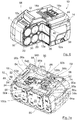
- the housing 10a of a battery pack 10 which is modular in the embodiments shown, is composed of several housing parts forming the housing as follows: a cell carrier 12, two side walls or side parts 14 (see also FIG Figure 2b ), which are detachably attached to the side of the cell carrier 12, as well as at least one housing cover 16 (cf. Fig. 4 ), which can be releasably placed on the cell carrier 12.
- a cell carrier 12 two side walls or side parts 14 (see also FIG Figure 2b ), which are detachably attached to the side of the cell carrier 12, as well as at least one housing cover 16 (cf. Fig. 4 ), which can be releasably placed on the cell carrier 12.
- the side parts 14 and the upper housing cover 16 as detachable housing parts are omitted for better illustration of the internal components of the battery pack 10.
- the cell carrier 12 of the Figures 1 to 7b defines a receiving space 30 for the battery cells 20 to be received and, in the embodiment shown, with a modular housing 10a forms a holding structure for the further housing parts to be attached thereto.
- the housing cover 16 is particularly in the Figures 1 and 6th and comprises at least two ventilation recesses 18a and 18b, via which cooling air from the surroundings of the battery pack 10 can penetrate into the interior of the housing and can be released back into the surroundings.
- the present battery pack 10 is therefore a so-called air-cooled battery pack.
- the present battery pack has a cooling space 12a which is formed in the cell carrier 12.
- the cooling space which is formed separately from the receiving space 30 of the battery cells 20, forms a cooling channel that is closed off from the receiving space 30 and has branches between the layers of several battery cells 20 and opens into slot-shaped ventilation openings 12b, which, when the battery pack 10 is installed, are aligned with the ventilation recesses 18a ( see. Fig. 5 ).
- the battery pack 10 comprises ten battery cells 20 which are arranged essentially parallel to one another. These are arranged in two layers. For example, how to use the Figure 6 can see, a branch of the channel-shaped cooling space 12a extends below the lower layer of the battery cells 20, a branching of the channel-shaped cooling space 12a between the lower layer of the battery cells 20 and the upper layer of the battery cells 20 and a further branch of the channel-shaped cooling space 12a above the upper one Location of the battery cells 20.
- the cell carrier 12 is composed of two essentially mirror-symmetrical holder parts 12c, which are assembled in a dividing plane.
- the cooling channel or channel-shaped cooling space 12a is formed in the area of this dividing plane and is closed in that the two holder parts 12c are connected.
- the dividing plane is the virtual plane that is connected to the circumferential dividing seam T (in Figure 4 ) coincides. In the Figures 5 and 6th a part of a holder part 12c is cut away so that the virtual parting plane can be seen and the interaction of the holder parts 12c can be understood.
- the battery cells 20 are electrically contacted via sheet metal conductors 22 in the region of their poles 20a and 20b, the metal conductor plates 22 in turn being electrically connected to a circuit board 24.
- the circuit board 24 can be equipped with a number of electronic components, which will not be discussed in more detail below.
- the printed circuit board 24 is detachably connected to the cell carrier 12 via screws that are not designated in any more detail.
- the cell carrier 12 For fastening the housing cover 16 and the side part 14, the cell carrier 12 also has fastening projections 26 with threaded recesses 26a, into which fastening screws (not shown) for fastening the housing cover 16 and the side part 14 can be screwed. Furthermore, the cell carrier 12 according to the invention comprises on its upper side 34 facing the printed circuit board at least one recess 28a, which can be used, for example, to introduce a temperature sensor or the like starting from the printed circuit board 24.
- the receiving space 30 delimited on the inside by the cell carrier 12 is provided with the Battery cells (cf. Figure 4 and Figure 6 ) encapsulated with a potting compound 30a (cf. Figure 2a and 3 ).
- the cylindrical battery cells 20 are inserted into the two-part cell carrier 12 and are flush with one another in one plane.
- conductor plates 22 as The battery cells 20 are connected to one another in series or in parallel and connected to the circuit board 24.
- the potting compound 30 is then poured into the receiving space 30 and seals the remaining cavities between the battery cells 20 and the cell carrier 12 in the interior of the receiving space 30.
- the conductor plates 22 are also encapsulated. Only in the area of the positive poles P1 of the battery cells 20 does a recess or cutout remain in order to ensure that the cells in this area, in which an overpressure valve is usually also provided on the cells 20, can outgas in the event of overheating.
- a particularly efficient coating of the battery cells 20 with the potting compound in the area of their outer surfaces in the interior of the cell carrier 12 is also achieved by the fact that the accommodated battery cells are not completely surrounded by the cell carrier 12 in the area of their outer surfaces, but only partially supported by rib-like projections 30b in the Inside the cell carrier 12 (cf. Figure 5 ) are included.
- the cell carrier has bearing sections 32 which are used to store the battery cells 20 are provided with a slight distance from each other.
- the side walls or side parts 14 of the housing of the battery pack 10 are also designed as detachable housing parts.
- the side cover 14 has fastening projections 36 which include bores 36a for receiving a screw.
- the screws (indicated by the reference numeral 46, cf. Fig. 1 ) can be screwed through the bores 36a of the fastening extension 36 into corresponding threaded bores 26a in the area of the fastening sections 26 of the cell carrier 12.
- the side cover 14 has an upper holding edge 38 which, in the assembled state of the battery pack 10, is supported by a corresponding holding edge 50 of the Housing cover 16 can be overlapped (cf. Figure 2b ) and a retaining edge 40, which in turn has a corresponding retaining edge 48 (cf. Figure 1 and Figure 6 ) of the cell carrier 12 is able to reach over in the assembled state of the battery pack 10.
- a circumferential fuse 44 is also provided, which in the assembled state of the associated side part 14 on the cell carrier 12 is able to seal the resulting pole area of the battery pack 10 airtight from the environment.
- This seal 44 can be designed, for example, as an elastomer seal or as a tongue and groove geometry.
- a sealing area 42 is provided in an area of the side parts 14 which, in the assembled state of the battery pack 10, comes into contact with the non-potted poles P1 of the individual battery cells 20.
- these sealing areas 42 are designed in one piece with the associated side part 14 and can also be designed, for example, as an elastomer seal or as a tongue and groove geometry.
- the side part 14 is composed of a soft component and a hard component, the soft component being provided in the sealing area 42 and comprising an elastomer, for example.
- areas with predetermined breaking points are in the area of the side parts 14 54 is provided, the reduced wall thickness of which enables the side part 14 to break through in the event of an overpressure in one of the pole regions P1 and thus an exchange of air into the interior of the housing.
- Sealing areas 42 are provided, it makes sense to assign a predetermined breaking point to each sealing area 42.
- the areas of the predetermined breaking points 54 are additionally surrounded by an annular projection 54a.
- This aspect of the invention is independent of the configuration with the use of one or more potting compounds and the specific configuration of the cell carrier and can assume several functions: on the one hand, these projections 54a are arranged and designed in such a way that the end faces of the cells received in the associated cell carrier 12 Battery cells 20 can come to rest on the annular projections 54a.
- these projections are made of an elastic material, shock absorption of the battery cells 20 is achieved, in particular if, as in the embodiment shown, no shoulder or the like is provided on the associated cell carrier on the receiving areas .
- the battery cells 20 are thus floatingly mounted in the cell carrier 12 in the direction of their longitudinal axis.
- FIG. 2b Another inventive aspect is also in the Figure 2b and relates in particular to battery packs with non-potted conductor plates 22.
- the side covers 14 additionally have separating webs 54b on their inside, which are arranged and aligned in such a way that in the assembled state they protrude between two adjacent assembled conductor plates 22 and separate them from one another.
- the conductor plates 22 have different voltages due to the connection of the battery cells 20, which is why such a separation of the electrical areas is advantageous. In this way, the risk of short circuits as a result of moisture, for example, in the case of non-potted conductor plates 22 can be reduced.
- corresponding intermediate webs can also be provided on the cell carrier, which cooperate with the intermediate webs 54b of the side covers 14 and together form a separating web between the adjacent conductor plates 22.
- separating elements as separating webs
- other design variants are also conceivable, for example as or with projections which, if necessary, interact with corresponding projections on the cell carrier to produce an electrical separation.
- a further receiving area 50 is provided for receiving the printed circuit board 24 with the electronic components.
- this is formed in one piece with the cell carrier 12 on its upper side and is opened in a direction facing away from the battery cells 20 and the associated receiving space 30.
- this second receiving space 50 for receiving the printed circuit board 24 is formed essentially separately from the first receiving space 30 for receiving the battery cells.
- the second receiving space 50 for receiving the circuit board 24 can be encapsulated with a potting compound 52 (cf. Figure 2a ).
- the ventilation openings 12a, 12b are aligned with corresponding openings or recesses 24a. 24b arranged on the printed circuit board 24 and also remain recessed in the potting compound 52 (cf. Figure 2a ).
- the potting compound 52 can be made of an identical material as the first potting compound 30a or a different material. Properties of the casting compound such as thermal conductivity, fire resistance and low inflammability as well as the lowest possible electrical conductivity are advantageous.
- the specific design of the housing of the battery pack according to the invention with a cooling space enclosed in the cell carrier 12 enables, on the one hand, air cooling of the battery cells accommodated therein, as a result of which the service life of the battery pack is significantly increased.
- metallic dust particles and / or air humidity carried along with the cooling air do not get into the area of the battery cells and possibly the electronics and thereby short circuits and in particular damage the battery pack.
- the potting compound used represents an additional measure to protect against metal dust and moisture and also serves to cool the battery pack.
- the cell carrier can also be used for heat dissipation. In this way, a particularly long-lasting and robust battery pack is provided.
- a number of electronic components are applied to the circuit board 24.
- This also includes a charge level indicator for the battery pack, which is generally designated by the reference number 60.
- this comprises four LEDs 64 (indicated in FIG Fig. 4 ), which are fitted on the circuit board 24, as well as a push button switch 62 (indicated in the Fig. 4 ) to operate the charge level indicator 60.
- Four corresponding openings 18a are provided in the housing cover 16, through which, on the one hand, an exchange of air with the surroundings of the battery pack 10 is made possible and, on the other hand, it can be seen from the outside whether the individual LEDs light up or not .
- the charge level indicator can be actuated in a known manner by pressing the pushbutton switch which extends through a further recess on the housing cover 16.
- the charge level indicator 60 is protected from dirt and moisture penetrating from the outside, it can also be partially encapsulated with the further potting compound 52 (as in FIG Fig. 2a shown).
- the further potting compound 52 is made of a light-conducting material so that the LEDs continue to glow from the outside.
- a sealing element 66 is provided, which is placed on the circuit board 24 before the encapsulation with the further encapsulation compound 52 and covers both the pushbutton switch 62 with a corresponding dome 62a and the LEDs laterally sealingly surrounds.
- Special recesses 64a in the sealing element 66 are assigned to the LEDs 64 so that they are not covered by the sealing element 66 and the LEDs 64 remain visible from the outside through the corresponding openings 18a in the housing cover 16.
- the sealing element 66 can be partially covered by the further potting compound 52, in particular in the area of the LEDs, whereby an improved sealing effect can be achieved.
- the dome section 62a which covers the pushbutton switch 62, is greater in its height, ie the extent perpendicular to the circuit board 24, than the further potting compound 52 in order to ensure that it can still be actuated (cf. for example Fig. 2a ).
- the sealing element 66 can in turn be formed from a light-permeable material, so that the recesses 64a can be dispensed with.
- the further sealing compound 52 has a lower height than the sealing element 66 in the region of its lowest height, so that it does not cover the sealing element 66.
- the sealing element 66 seals the pushbutton switch 62 from the outside and the elements of the charge level indicator 60 from the further potting compound 52 (see also FIG Figure 7b ).
- connection blades also known as connection springs or contact springs
- connection blades also known as connection springs or contact springs
- connection springs or contact springs in the Figure 7a five are shown
- the connecting swords 56 overlapped by an electronics cup 70 which has a number of connection slots 72 which are assigned to the respective connection points formed by the connection blades 56.
- a second sealing element 74 is placed on the further potting compound 52. This serves to compensate for play and to allow the electronics cup to sit tightly on the further potting compound 52.
- the second sealing element 74 can in principle also be placed on the circuit board 24 before the encapsulation and encapsulated with the further encapsulation compound 52. In this case it is to choose the height of the second sealing element 74 so that it is greater than the height of the potting compound so that it is not covered by the potting compound and can continue to develop its play-compensating effect.
- the first and the second sealing element 66 and 74 can each be made from an elastic material, for example from foam rubber or the like.
- the cell carrier can have positioning aids that extend outward in a substantially perpendicular direction from the support plane A of the second receiving space 50 for the printed circuit board and serve both to position the printed circuit board and the applied sealing elements can.
- corresponding recesses are provided on the sealing elements 66 and 74.
- FIGS 7a and 7b a further special feature of the present battery pack 10 can be seen in the form of the connecting bridges 80. These serve to connect the conductor plates 22 to the circuit board 24. They have a curved cross section.
- a first end 82 is electrically and mechanically connected to the circuit board 24, for example soldered onto it and / or inserted with a fastening projection 80 a in a form-fitting manner in a corresponding recess on the circuit board 24.
- a second end 84 is provided for connection to a conductor plate 22 and protrudes from the further receiving space 50 in such a way that, in the event of potting with the further potting compound 52, this is not also potted.
- the connecting web 86 between the two ends 82 and 84 is curved and enables the second end to extend out of the further receiving space 50 in the direction of the conductor plate 22 to be connected, as a result of which simple and strand-free contact is achieved.
- the conductor plates 22 can also be electrically connected to the connecting bridges 80 by means of a solder connection. Alternative and additional types of connection that enable electrical contact to be made between the connecting bridges and the conductor plates and / or the circuit board are of course also conceivable.
- Small recesses or receptacles 88 can be provided on the cell carrier 12 in the area of the boundary walls of the further receiving space 50 (cf. Figures 7a, 7b ) through which the connecting bridges 80 can extend. These are also used for the defined attachment of the connecting bridges 80 to the printed circuit board 24. In principle, these can also be dispensed with if the connecting webs 86 are configured accordingly.
- connection plates 90a and 90b form a special form of the connecting bridges, which also enable an electrical connection of the associated conductor plates 22 to the electrical interface of the battery pack 10.
- these have a first end 92a, b and second end 94a, b as well as an associated connecting web 96a, b, which enables electrical contact to be made with the associated conductor plates 22 even after the circuit board 24 has been completely potted.
- connection plate 90a indirectly contacts a first end connection blade 56a of the electrical interface of the battery pack 10 via an interposed first fuse 100a, while the connection plate 90b contacts a second end connection blade 56b indirectly via an interposed second fuse 100b.
- fastening projections 98a, 98b are also provided, which extend in a manner analogous to the fastening projections 80a in the direction of the circuit board 24 and are received in corresponding receptacles on the circuit board 24 for a defined arrangement on the circuit board 24 .
- the connecting bridges and connection plates make it possible to place the circuit board 24 on the cell carrier 12 in the further receiving space 50 at a comparatively early point in time in the assembly process to be attached and to be cast with the further casting compound 52.
- the circuit board 24 is coated with the further potting compound 52 in all areas, except in the area of the pushbutton switch 62 over which the sealing element 66 overlaps.
- electrical contacting of the circuit board for connection to the battery cells would no longer be possible as a result of the coating with the additional potting compound.
- the particularly early fitting of the circuit board to the cell carrier and also early protection of the circuit board by the additional potting compound is very advantageous, since this considerably simplifies handling in the assembly process.
- the early potting enables reliable curing of the further potting compound without further assembly having to be delayed for this.
- the further potting compound 52 not only provides protection for the circuit board 24 against external influences, but also fixes the encapsulated elements attached to the circuit board 24, i.e. the sealing element 66, the connecting bridges 80 and the connection plates 90, by means of a material bond.
- Potting the circuit board with a further potting compound also enables a comparatively simple and inexpensive design of a fuse 100a, 100b. This can also be achieved using a simple sheet metal part.
- the fuses 100a, 100b are formed by a sheet metal part with a first end and a second end, which are each connected to one another by a connecting web.
- the two first ends each serve to make electrical contact with the associated fuse 100a, b with a connection plate 90a, b and the two second ends each serve to make electrical contact with the associated fuse 100a, b with a connecting blade 56a, b of the electrical interface of the battery pack 10.
- the two ends 102 and 104 are also bent over in the manner of the fastening projections 80a, 98a, 98b and engage in corresponding recesses in the circuit board 24 in order to establish a defined arrangement on the circuit board 24 and electrical connection with the ensure the respective connecting parts.
- Alternative types of connection are alternatively or additionally also conceivable.
- the fuses 100a, 100b are also covered at least in sections by the potting compound 52 and secured by this.
- the potting compound 52 can thus replace the function of an additional housing, which is provided as purchased parts in certified fuses. This makes it possible to provide a fuse which is particularly simple and inexpensive to manufacture and which is at the same time just as reliable in its function as the known certified fuses.
- the further potting compound 52 thus not only serves as protection for the printed circuit board 24 in the installed state, but together with the sealing element 66 also enables the pushbutton to be securely sealed, and provides a reliable (cohesive) fixation of the circuit board 24 via a form fit attached connecting bridges, connection plates and fuse parts ready and replaces a fuse housing for the fuses 100a, 100b.
- the cell carrier 12 and the further housing parts 14, 16, 70 are initially formed from, for example, a plastic, for example by means of injection molding. Depending on the design of the side parts 14, for example, several plastic components, for example a hard component and a soft component, can be used in different areas.
- the printed circuit board 24 is equipped with the necessary electronic components and provided with an electrical interface in the form of, for example, connection blades 56 and the necessary recesses.
- the connecting bridges 80, connecting plates 90 and fuses 100 are punched out of sheet metal plates and bent accordingly.
- the circuit board 24 is additionally equipped with the connecting bridges 80, connection plates 90 and fuses 100 and inserted into the further receiving space 50 of the cell carrier 12.
- the sealing elements 66 and 74 are placed on the area of the charge level indicator 60 or the connecting blades 56. If necessary, additional elements are added; For example, a temperature sensor can be provided which is inserted into the receiving space 30 for the battery cells.
- the printed circuit board 24 is completely provided with all the elements to be connected to it, it is cast with the further potting compound 52. This covers almost the entire circuit board 24. Only in the area of the sealing elements 66, 74 do the latter prevent the surface of the circuit board 24 from being wetted with the further potting compound 52.
- the further potting compound 52 can now harden and protect the electronics, so that the pre-assembled assembly of cell carrier 12 and electronics is enabled.
- the cell carrier 12 is equipped with the battery cells. These are connected to the electronics of the circuit board 24 by means of conductor plates via the second ends of the connecting bridges 80 and the connection plates 90.
- the receiving space 30 is then filled with the casting compound and also reliably seals the receiving space 30.
- the other housing parts are attached, i.e. the side parts 14 are attached to the side and the sealing element 74 is placed on the top of the battery in the area of the electrical interface of the battery pack 10 around the connecting blades 56 protruding from the potting compound 52 on the further potting compound 52.
- the electronics cup 70 can then be placed on the sealing element 74 before the housing cover 16 is placed, which at the same time also partially overlaps the side parts 14 and secures them in a form-fitting manner.
- the side parts 14 and the housing cover 16 are releasably fixed to the cell carrier 12 with screws.
Abstract
Die Erfindung betrifft ein Akkupack (10) für eine Handwerkzeugmaschine umfassend wenigstens eine Akkuzelle (20), einen Zellenträger (12) zur abschnittsweisen Aufnahme und Lagerung der wenigstens einen Akkuzelle (20) in einem Aufnahmeraum (30) des Zellenträgers (12), eine Vergussmasse (30a), die in montiertem Zustand des Akkupacks (10) im Aufnahmeraum (30) des Zellenträgers (12) Zwischenräume zwischen dem Zellenträger (12) und der wenigstens einen darin aufgenommenen Akkuzelle (20) ausfüllt. Erfindungsgemäß weist der Zellenträger (12) ferner wenigstens einen geschlossenen Kühlraum (12a) auf, der von dem Aufnahmeraum (30) getrennt in dem Zellenträger (12) ausgebildet ist und über Belüftungsöffnungen (12b) in Austausch mit der Umgebung steht, so dass der Kühlraum (12a) von Kühlluft durchströmt werden kann.

Description
Die vorliegende Erfindung betrifft ein Akkupack für eine Handwerkzeugmaschine mit wenigstens einer Akkuzelle, einem Zellenträger zur abschnittsweisen Aufnahme und Lagerung der wenigstens einen Akkuzelle in einem Aufnahmeraum des Zellenträgers sowie einer Vergussmasse, die in montiertem Zustand des Akkupacks im Aufnahmeraum des Zellenträgers Zwischenräume zwischen dem Zellenträger und der wenigstens einen darin aufgenommenen Akkuzelle ausfüllt.The present invention relates to a battery pack for a handheld power tool with at least one battery cell, a cell carrier for receiving and storing the at least one battery cell in sections in a receiving space of the cell carrier and a potting compound which, in the assembled state of the battery pack, creates spaces between the cell carrier and the at least one battery cell accommodated therein fills.
Akkupacks mit einer oder mehreren Akkuzellen sind aus dem Stand der Technik in unterschiedlichen Größen mit einer unterschiedlichen Anzahl parallel und in Reihe geschalteter Zellen bekannt, wodurch die von dem Akkupack bereitgestellte Kapazität und die bereitgestellte Spannung an den jeweiligen Einsatzzweck angepasst werden können. Vorliegend ist das Akkupack insbesondere für Handwerkzeugmaschinen geeignet. Selbstverständlich lässt sich die vorliegende Erfindung auch an andere Einsatzzwecke anpassen und kann beispielsweise bei elektrisch betriebenen Kraftfahrzeugen oder dergleichen Anwendung finden. Die wenigstens eine Akkuzelle kann als Lithium-Ionen-Akkuzelle oder als Nickel-Metall-hybrid-Akkuzelle oder dergleichen ausgebildet sein. Im Falle mehrerer Akkuzellen ist es üblich, dass in einem Akkupack Akkuzellen eines Zellentyps verwendet werden. Es kann aber auch für einige Anwendungen sinnvoll sein, Akkuzellen unterschiedlicher Zellentypen einzusetzen.Battery packs with one or more battery cells are known from the prior art in different sizes with a different number of cells connected in parallel and in series, as a result of which the capacity and voltage provided by the battery pack can be adapted to the respective application. In the present case, the battery pack is particularly suitable for handheld power tools. Of course, the present invention can also be adapted to other uses and can be used, for example, in electrically operated motor vehicles or the like. The at least one battery cell can be designed as a lithium-ion battery cell or as a nickel-metal hybrid battery cell or the like. In the case of several battery cells, it is common practice to use battery cells of one cell type in one battery pack. However, it can also be useful for some applications to use battery cells of different cell types.
Insbesondere bei der Verwendung von Lithium-Ionen-Akkuzellen können die im Betrieb auftretenden Umwelteinflüsse, wie z. B. Wasser und Metallstaub, im Falle eines Einsatzes des Akkupacks in einer Handwerkzeugmaschine zu Kurzschlüssen oder Korrosion führen, so dass das Akkupack beschädigt oder sogar zerstört wird. Daher besteht eine bekannte Aufgabe im Zusammenhang mit Akkupacks für Handwerkzeugmaschinen darin, die Akkuzellen insbesondere vor derartigen Umwelteinflüssen zu schützen.Especially when using lithium-ion battery cells, the environmental influences occurring during operation, such as. B. water and metal dust, if the battery pack is used in a handheld power tool, lead to short circuits or corrosion, so that the battery pack is damaged or even destroyed. A known task in connection with battery packs for handheld power tools is therefore to protect the battery cells in particular from such environmental influences.
Eine weitere Problemstellung resultiert aus der im Zusammenhang mit Handwerkzeugmaschinen benötigten hohen Leistungsfähigkeit des Akkupacks. Üblicherweise befinden sich in einem Akkupack mehrere Lithium-Ionen-Zellen, die Wärme erzeugen. Je größer der Entladestrom der Zellen ist, desto mehr Wärme wird erzeugt. Um die Akkuzellen vor einer Zerstörung oder Beschädigung durch diese entstehende Wärme zu schützen, ist es üblich, dass die Akkupackelektronik bei einer zu großen Temperatur an den Zellen die weitere Entladung des Akkupacks unterbricht, so dass der Anwender mit diesem Akkupack bis zu dessen Abkühlung nicht weiter arbeiten kann.Another problem arises from the high efficiency of the battery pack required in connection with handheld power tools. Usually there are several lithium-ion cells in a battery pack, the Generate heat. The greater the discharge current of the cells, the more heat is generated. In order to protect the battery cells from being destroyed or damaged by the resulting heat, it is common for the battery pack electronics to interrupt further discharge of the battery pack if the temperature of the cells is too high, so that the user cannot continue with this battery pack until it has cooled down can work.
Daher ist es inzwischen ebenfalls üblich geworden, Lösungen in dem Akkupack bereitzustellen, die eine zuverlässige Abführung der entstehenden Wärme ermöglichen. Hierdurch kann entweder länger mit dem Akkupack gearbeitet werden oder mit einem höheren Entladestrom entladen werden, was gleichbedeutend mit einer höheren Leistungsfähigkeit des Akkupacks ist.It has therefore now also become customary to provide solutions in the battery pack which enable the heat that is generated to be reliably dissipated. This means that you can either work longer with the battery pack or discharge it with a higher discharge current, which is synonymous with a higher capacity of the battery pack.
Eine bekannte Lösung sieht vor, dass das Innere des Akkupacks mit Hilfe eines von außen eindringenden Kühlluftstroms gekühlt wird, wie beispielsweise in der
Eine weitere Lösung ist in der Druckschrift
Wenngleich diese Lösung eine zuverlässige Kühlung der Akkuzellen ermöglicht, so führt das Vorsehen von zusätzlichen Verbindungsplatten, wie beschrieben, zu einer nennenswerten Erhöhung des Gewichts der Batterie. Bei der beschriebenen Lösung ist dies insofern nicht so relevant, als dass diese insbesondere in elektrisch betriebenen Fahrzeugen zum Einsatz kommen kann. Im Falle einer Handwerkzeugmaschine, die von einem Anwender gehalten werden muss, kann der Gewichtsunterschied von einigen Gramm schon für die Handhabung äußerst relevant sein, weshalb diese Lösung als nachteilig anzusehen ist. Wird auf die Verbindungsplatten verzichtet, so ist die Wärmeableitung, selbst bei einer Vergussmasse, die aus einem thermisch leitfähigen Material gefertigt ist, weniger effizient und es kann wiederum zu einer Überwärmung des Akkupacks kommen.Although this solution enables reliable cooling of the battery cells, the provision of additional connecting plates, as described, leads to a significant increase in the weight of the battery. In the case of the solution described, this is not so relevant insofar as it can be used in particular in electrically operated vehicles. In the case of a handheld power tool that has to be held by a user, the weight difference of a few grams can already be extremely relevant for handling, which is why this solution is to be viewed as disadvantageous. If the connection plates are not used, the heat dissipation is less efficient, even with a potting compound made from a thermally conductive material, and the battery pack can again overheat.
Aus der
Weiterhin sind die Akkuzellen nach dem Einsetzen in die Ausnehmungen des Zellhalters mit der Vergussmasse vergossen, wobei die Vergussmasse einen geringen Wärmewiderstand aufweist, wie z. B. eine Vergussmasse auf Silikonbasis. Die Vergussmasse füllt Zwischenräume zwischen den Akkuzellen und dem Zellhalter aus und ermöglicht somit eine besonders gute Wärmeübertragung von den Akkuzellen auf den Zellhalter. Zudem kann mittels der Vergussmasse ein Eindringen von Feuchtigkeit und/oder Flüssigkeiten vermieden werden, so dass die darin eingegossenen Bauteile vor Feuchtigkeit geschützt sind. Korrosion, Fehlströme oder Kurzschlüsse können so verringert werden.Furthermore, after being inserted into the recesses of the cell holder, the battery cells are encapsulated with the potting compound, the potting compound having a low thermal resistance, e.g. B. a silicone-based potting compound. The potting compound fills gaps between the battery cells and the cell holder and thus enables particularly good heat transfer from the battery cells to the cell holder. In addition, penetration of moisture and / or liquids can be avoided by means of the potting compound, so that the components cast therein are protected from moisture. Corrosion, fault currents or short circuits can thus be reduced.
Auch bei dieser Lösung ist jedoch ein zusätzliches Element, nämlich insbesondere ein Kühlkörper aus Metall vorgesehen, der wiederum zu einer Gewichtserhöhung des Akkupacks führt.In this solution too, however, an additional element is provided, namely in particular a metal heat sink, which in turn leads to an increase in the weight of the battery pack.
Schließlich beschreibt die
Bei dieser Lösung wird auf eine Durchlüftung, wie sie vorstehend aus dem Stand der Technik bekannt beschrieben ist, vermieden, und die Kühlung des Akkupacks erfolgt über eine passive Kühlung an der Außenoberfläche des Gehäuses. Auch diese Lösung ist, wenngleich sie eine zuverlässige Kühlung des Akkupacks und zugleich einen guten Schutz vor äußeren Einflüssen bereitstellt, weniger effizient bezüglich der Wärmeabführung als die bekannte Lösung einer Luftkühlung des Akkupacks.With this solution, ventilation, as described above from the prior art, is avoided, and the battery pack is cooled by passive cooling on the outer surface of the housing. This solution, too, although it provides reliable cooling of the battery pack and at the same time good protection against external influences, is less efficient in terms of heat dissipation than the known solution of air cooling of the battery pack.
Weiterhin ist es aus dem Stand der Technik auch bekannt, eine mit elektronischen Bauteilen bestückte Leiterplatte eines Akkupacks in einer Aufnahmeschale eines Akkugehäuses aufzunehmen. Aufgrund der spezifischen konstruktiven Ausgestaltung der
Auf der Leiterplatte sind LEDs angeordnet, die über die zugeordneten Anzeigefenster von außen wahrnehmbar sind. Weiterhin ist auch ein Taster als Betätigungselement auf der Leiterplatte angebracht, der über das Betätigungsfeld an dem Gehäuse von außen bedienbar sein soll. Um zu gewährleisten, dass weder die als Anzeigeelemente genutzten LEDs noch das Betätigungselement durch die Vergussmasse unbrauchbar werden, ist ein Dichtelement vorgesehen, das in der Art eines Dichtrands beispielsweise aus Moosgummi, die Anzeigeelemente und das Betätigungselement dichtend umgibt, so dass die abgetrennten Räume frei von der Vergussmasse bleiben. Hierzu erstreckt sich das Dichtelement über die gesamte Höhe des Füllraums, wobei es zwischen der Leiterplatte und dem Boden der Aufnahmeschale verspannt gehalten ist.LEDs are arranged on the circuit board and can be seen from the outside via the associated display windows. Furthermore, a button is attached as an actuating element on the circuit board, which should be operable from the outside via the actuating field on the housing. In order to ensure that neither the LEDs used as display elements nor the actuating element become unusable due to the potting compound, a sealing element is provided which, in the manner of a sealing edge, for example made of foam rubber, surrounds the display elements and the actuating element in a sealing manner, so that the separated spaces are free of of the potting compound. For this purpose, the sealing element extends over the entire height of the filling space, it being held clamped between the circuit board and the bottom of the receiving shell.
Anders als bei der vorstehend beschriebenen Lösung, ist es aus dem Stand der Technik ebenfalls bekannt, die Leiterplatte zumindest teilweise mit einer Vergussmasse zu vergießen, um sie in diesen Bereichen vor Umwelteinflüssen zu schützen. Die
Im Falle von elektrischen Überlasten ist zum Schutz der elektronischen Bauteile und der Akkuzellen eines Akkupacks üblicherweise wenigstens eine Sicherung vorgesehen. Üblicherweise wird diese als zertifiziertes Zukaufteil in dem Stromkreis des Akkupacks eingesetzt. Alternativen zu derartigen zertifizierten Sicherungen erfordern immer ein stromleitendes Bauteil sowie ein Gehäuse, das das stromleitende Bauteil einhaust, damit dieses, wenn es ab einem bestimmten Schwellenwert zerstört wird, um den Stromkreis zu unterbrechen, keine Beschädigung der weiteren elektrischen Bauteile zur Folge hat. Diesbezüglich wird beispielhaft auch auf die
Demgegenüber besteht eine Aufgabe der vorliegenden Anmeldung, ein Akkupack mit einer verbesserten Kühlwirkung und zugleich einem verlässigen Schutz vor Außeneinflüssen jedweder Art bereitzustellen, das insbesondere bei Handwerkzeugmaschinen zum Einsatz kommen kann.In contrast, it is an object of the present application to provide a battery pack with an improved cooling effect and at the same time reliable protection against external influences of any kind, which can be used in particular in handheld power tools.
Demgegenüber schlägt die vorliegende Erfindung einen Akkupack mit den Merkmalen des Anspruchs 1 vor.In contrast, the present invention proposes a battery pack with the features of claim 1.
Bei der erfindungsgemäßen Lösung weist der Zellenträger ferner wenigstens einen geschlossenen Kühlraum auf, der von dem Aufnahmeraum getrennt in dem Zellenträger ausgebildet ist und über Belüftungsöffnungen in Austausch mit der Umgebung steht, so dass der Kühlraum von Kühlluft durchströmt werden kann.In the solution according to the invention, the cell carrier also has at least one closed cooling space, which is formed separately from the receiving space in the cell support and communicates with the environment via ventilation openings, so that cooling air can flow through the cooling space.
Anders als im Stand der Technik wird somit nicht ein zusätzliches Kühlelement, welches ein zusätzliches Gewicht für das Akkupack mit sich bringt, zur Kühlung des Akkupacks vorgesehen, sondern ein zusätzlicher von dem Aufnahmeraum getrennt in dem Zellenträger ausgebildeter Kühlraum im Inneren des Akkupacks, über den im Inneren des Akkupacks entstehende Wärme, insbesondere im Bereich von Wärmehotspots über die Vergussmasse und den Zellenträger an die den Kühlraum durchströmende Kühlluft abgegeben werden kann.Unlike in the prior art, an additional cooling element, which entails additional weight for the battery pack, is not provided for cooling the battery pack, but an additional cooling space in the interior of the battery pack, which is separate from the receiving space in the cell carrier, via which the Heat generated inside the battery pack, in particular in the area of hot spots, via the potting compound and the cell carrier to which the cooling air flowing through the cooling space can be given off.
Die Temperaturverteilung innerhalb der Zellanordnung wird durch eine Vielzahl von Faktoren, wie beispielsweise durch die Art der verwendeten Akkuzellen, die relative Anordnung der Akkuzellen zueinander im Falle von mehreren Akkuzellen, der durch die Akkuzellen fließende Lade- bzw. Entladestrom und der Alterungszustand der jeweiligen Akkuzellen beeinflusst. Als Wärmehotspots werden insbesondere die Bereiche mit erhöhter bzw. mit hohen auftretenden Temperaturen im Betrieb bezeichnet.The temperature distribution within the cell arrangement is influenced by a large number of factors, such as the type of battery cells used, the relative arrangement of the battery cells to one another in the case of several battery cells, the charging or discharging current flowing through the battery cells and the aging status of the respective battery cells . The areas with increased or high temperatures occurring during operation are particularly referred to as heat hotspots.
Wie bereits im Stand der Technik bekannt, kann die Vergussmasse insbesondere aus einem thermisch leitfähigen Material hergestellt sein.As already known in the prior art, the potting compound can in particular be made from a thermally conductive material.
Dadurch, dass die Vergussmasse Zwischenräume zwischen dem Zellenträger und der wenigstens einen darin aufgenommenen Akkuzelle ausfüllt, kann eine Wärmeübertragung von wenigstens einer aufgenommenen Akkuzelle auf den Zellenträger besonders gut sein. Zudem wird mittels der Vergussmasse das Eindringen von Flüssigkeit und/oder Feuchtigkeit vermieden wie auch das Eindringen von Metallstaub oder dergleichen, so dass die Akkuzelle besonders gut vor äußeren Einflüssen geschützt ist.Because the potting compound fills spaces between the cell carrier and the at least one accumulator cell accommodated therein, heat transfer from at least one accumulator cell accommodated to the cell carrier can be particularly good. In addition, the penetration of liquid and / or moisture as well as the penetration of metal dust or the like is avoided by means of the potting compound, so that the battery cell is particularly well protected from external influences.
Auch der Zellenträger kann seinerseits aus einem wärmeleitfähigen Material hergestellt sein, um eine besonders gute Wärmeableitung zu gewährleisten. Beim Laden oder Entladen der wenigstens einen Akkuzelle im Inneren des Akkupacks auftretende Wärme kann durch den unmittelbaren Kontakt mit dem Zellenträger oder der Vergussmasse an diese Komponenten weitergegeben werden, welche wiederum in Kontakt miteinander stehen, und durch die Kühlluft, welche durch den Kühlraum fließt, gekühlt werden können.The cell carrier can also be made of a thermally conductive material in order to ensure particularly good heat dissipation. When charging or discharging the at least one battery cell inside the battery pack, heat can be passed on to these components through direct contact with the cell carrier or the potting compound, which in turn are in contact with one another and cooled by the cooling air flowing through the cooling space can be.
Erfindungsrelevant ist dabei, dass der Kühlraum von dem Aufnahmeraum getrennt in dem Zellenträger ausgebildet ist und derartig geschlossen ist, dass die Kühlluft nicht in den Aufnahmeraum eindringen kann. Damit ein Austausch mit der Umgebung stattfinden kann, befinden sich die Belüftungsöffnungen an dem Zellenträger, die den Kühlraum mit der Umgebung fluidisch verbinden, so dass der Kühlraum von der Kühlluft durchströmt werden kann.It is relevant to the invention that the cooling space is formed separately from the receiving space in the cell carrier and is closed in such a way that the cooling air cannot penetrate into the receiving space. So that an exchange with the surroundings can take place, the ventilation openings are located on the cell carrier, which fluidically connect the cooling space with the surroundings so that the cooling air can flow through the cooling space.
Zur Verbesserung einer solchen Durchströmung können insbesondere auch bekannte Komponenten an einem korrespondierenden Ladegerät und an der Handwerkzeugmaschine beitragen, insbesondere Lüfter und korrespondierende Belüftungsöffnungen, die dann, wenn das Akkupack an dem Ladegerät angeschlossen oder an der Handwerkzeugmaschine angebracht ist, den Belüftungsöffnungen des Akkupacks fluchten.In particular, known components on a corresponding charger and on the handheld power tool can also contribute to improving such a flow, in particular fans and corresponding ventilation openings which are aligned with the ventilation openings of the battery pack when the battery pack is connected to the charger or attached to the handheld power tool.
Wie bereits vorstehend erwähnt, kann die Vergussmasse insbesondere aus einem wärmeleitfähigen aber auch wasserundurchlässigen und/oder flammgeschützten Material hergestellt sein. Die Vergussmasse erfüllt im Wesentlichen die Funktion, die beim Laden und Entladen des Akkupacks entstehende Wärme im Akkupack gleichmäßig zu verteilen und an die Umgebung abzugeben. Darüber hinaus verhindert sie die Ablagerungen von Wasser oder Metallspänen bzw. das Eindringen von Feuchtigkeit an kritischen stromführenden Bereichen.As already mentioned above, the potting compound can in particular be made of a thermally conductive but also water-impermeable and / or flame-retardant material. The potting compound essentially fulfills the function of evenly distributing the heat generated during charging and discharging of the battery pack in the battery pack and of releasing it to the environment. In addition, it prevents the build-up of water or metal chips or the penetration of moisture in critical current-carrying areas.
Insbesondere können auch die Polbereiche der Zellen, an denen die Einzelzellen - sofern mehrere vorgesehen sind - mit Blechteilen zu einem Zellenverbund verschweißt werden und/oder mit einer Elektronikeinheit des Akkupacks verbunden werden, mit Vergussmasse vergossen sein.In particular, the pole areas of the cells on which the individual cells - if several are provided - are welded to sheet metal parts to form a cell assembly and / or are connected to an electronics unit of the battery pack, can also be encapsulated with potting compound.
Für den Fall, dass mehrere Akkuzellen in dem Akkupack aufgenommen sind, können diese parallel zueinander angeordnet im Akkupack aufgenommen und gelagert sein. Dabei kann vorgesehen sein, dass diese in gleicher Polaritätsrichtung angeordnet sind, das heißt, dass in einem montierten Zustand des Akkupacks die positiven und negativen Zellenpole der galvanischen Zellen der Akkuzellen jeweils nebeneinander zu liegen kommen. Alternativ ist es selbstverständlich auch möglich, die Akkuzellen in ungleicher Polaritätsrichtung zueinander anzuordnen. Während eines Montagevorgangs des Akkupacks können die Akkuzellen vorteilhaft gleichsinnig und/oder in einer gleichen Montagerichtung montiert werden. Eine Serien- oder eine Parallelschaltung der Akkuzellen kann ausschließlich durch entsprechend angepasste Leiterbleche als Verbindungsleiter auf einer oder beiden Seiten möglich sein.In the event that several battery cells are received in the battery pack, they can be accommodated and stored in the battery pack, arranged parallel to one another. It can be provided that these are arranged in the same polarity direction, that is, when the battery pack is in the assembled state, the positive and negative cell poles of the galvanic cells of the battery cells each come to lie next to one another. Alternatively, it is of course also possible to arrange the battery cells in opposite polarity directions to one another. During an assembly process of the battery pack, the battery cells can advantageously be assembled in the same direction and / or in the same assembly direction. A series or parallel connection of the battery cells can only be possible using appropriately adapted conductor plates as connecting conductors on one or both sides.
Weiterhin ist es möglich, dass die Akkuzellen derartig im Zellenträger aufgenommen sind, dass der größte Teil der Mantelfläche der Zellen frei zugänglich ist und somit von der Vergussmasse direkt benetzt werden kann, um eine ideale Wärmeabfuhr zu gewährleisten. Dabei können die Zellen beispielsweise nur im Bereich ihrer freien Enden bzw. im Bereich ihrer Pole in korrespondierenden Aufnahmen des Zellenträgers gelagert sein und gegebenenfalls auch beabstandet zueinander angeordnet sein. Bezüglich einer denkbaren Anordnung der Akkuzellen im Inneren des Zellenträgers wird beispielhaft auf die weitere Anmeldung
Die an sich bekannte Technologie der Luftkühlung stellt gegenüber passiven Kühlungslösungen, wie mit Hilfe eines Kühlkörpers oder dergleichen, eine besonders schnelle und effiziente Kühlung des Akkupacks bereit. Dies wirkt sich nicht nur im Betrieb des Akkupacks aus, sondern auch bei den Ladezeiten des Akkupacks am Ladegerät, insbesondere dann, wenn das Ladegerät ebenfalls eine Luftkühlfunktion bereitstellt.The technology of air cooling, which is known per se, provides particularly fast and efficient cooling of the battery pack compared to passive cooling solutions, such as with the aid of a heat sink or the like. This has an effect not only on the operation of the battery pack, but also on the charging times of the battery pack on the charger, in particular when the charger also provides an air cooling function.
Weiterhin kann vorgesehen sein, dass der Zellenträger wenigstens zwei Zellenträgerteile aufweist, die in montiertem Zustand des Akkupacks miteinander verbunden sind. Durch diese spezifische Ausgestaltung wird eine besonders einfache Herstellung des Zellenträgers ermöglicht.Furthermore, it can be provided that the cell carrier has at least two cell carrier parts which are connected to one another when the battery pack is installed. This specific configuration enables a particularly simple production of the cell carrier.
Insbesondere kann vorgesehen sein, dass die wenigstens zwei Zellenträgerteile im montierten Zustand des Akkupacks gemeinsam den Kühlraum begrenzen.In particular, it can be provided that the at least two cell carrier parts jointly delimit the cooling space in the assembled state of the battery pack.
Weiterhin kann vorgesehen sein, dass der Kühlraum einen Kühlluftkanal umfasst, der in der Trennungsebene der wenigstens zwei Zellenträgerteile verläuft. Dabei können die beiden Zellenträgerteile im Verbindungsbereich, d. h. in dem Bereich, in dem sie im montierten Zustand des Akkupacks miteinander verbunden sind, jeweils einen zu dem zu verbindenden Zellenträgerteil geöffneten Kühlkanal aufweisen, welcher erst durch das Miteinander-Verbinden der beiden Zellenträgerteile geschlossen wird. Bei einer einfachen Ausgestaltungsvariante liegt der Verbindungsbereich in einer Ebene, der sogenannten Teilungsebene. Diese Ausgestaltungsvariante ist besonders einfach und kostengünstig in der Herstellung des Zellenträgers umzusetzen. Andere Gestaltungsvarianten, bei denen der Verbindungsbereich nicht in einer Ebene verläuft, sind selbstverständlich ebenfalls denkbar.Furthermore, it can be provided that the cooling space comprises a cooling air duct which runs in the plane of separation of the at least two cell support parts. The two cell support parts in the connection area, d. H. in the area in which they are connected to one another in the assembled state of the battery pack, each have a cooling channel which is open to the cell carrier part to be connected and which is only closed when the two cell carrier parts are connected to one another. In a simple design variant, the connection area lies in one plane, the so-called dividing plane. This embodiment variant is particularly simple and inexpensive to implement in the production of the cell carrier. Other design variants in which the connection area does not run in one plane are of course also conceivable.
Unabhängig von der spezifischen Ausgestaltung des Zellenträgers kann in Kombination mit den vorstehenden Merkmalen oder losgelöst davon das Akkupack ferner ein modulares Gehäuse aufweisen, dass neben dem Zellenträger wenigstens ein mit dem Zellenträger verbindbares Gehäuseteil, insbesondere zwei Seitenteile und einen Gehäusedeckel umfasst. Das zusätzliche Gehäuseteil kann ferner, insbesondere im Falle eines Gehäusedeckels, eine Struktur zur lösbaren Verbindung mit einem Elektrohandwerkzeuggerät und/oder Kontaktelemente zur elektrischen Verbindung mit einem Elektrohandwerkzeuggerät oder einem Akkuladegerät aufweisen.Regardless of the specific configuration of the cell carrier, in combination with the above features or separately from them, the battery pack can also be a have modular housing that, in addition to the cell carrier, comprises at least one housing part that can be connected to the cell carrier, in particular two side parts and a housing cover. The additional housing part can furthermore, in particular in the case of a housing cover, have a structure for detachable connection to an electric hand tool device and / or contact elements for electrical connection to an electric hand tool device or a battery charger.
Je nach Anzahl der in dem Gehäuse aufgenommenen Zellen und nach Ausrichtung der Zellen zueinander kann beispielsweise auch nur ein Seitenteil vorgesehen sein. So kann vorgesehen sein, dass die Akkuzellen in gleicher Polaritätsrichtung angeordnet sind, das heißt, dass in einem montierten Zustand des Akkupacks die positiven und negativen Zellenpole der galvanischen Zellen der Akkuzellen jeweils nebeneinander zu liegen kommen. In diesem Fall kann ebenfalls ein einziges mit dem Zellenträger verbindbares Gehäuseteil, beispielsweise nur ein Seitenteil vorgesehen sein.Depending on the number of cells accommodated in the housing and on the alignment of the cells with respect to one another, for example only one side part can be provided. It can thus be provided that the battery cells are arranged in the same polarity direction, that is, when the battery pack is in an assembled state, the positive and negative cell poles of the galvanic cells of the battery cells each come to lie next to one another. In this case, a single housing part that can be connected to the cell carrier, for example only one side part, can also be provided.
Bei der modularen Ausgestaltung des Gehäuses bildet der Zellenträger eine tragende Struktur für das wenigstens eine daran befestigbare Gehäuseteil, das insbesondere lösbar an dem Zellenträger angebracht sein kann, beispielsweise mittels Schrauben oder dergleichen.In the case of the modular design of the housing, the cell carrier forms a supporting structure for the at least one housing part that can be fastened to it and which can in particular be detachably attached to the cell carrier, for example by means of screws or the like.
Es kann weiterhin vorgesehen sein, unabhängig von der spezifischen Ausgestaltung des Gehäuses als modulares Gehäuse und unabhängig von der spezifischen Ausgestaltung des Zellenträgers, in Kombination damit oder ohne diese, dass die wenigstens eine Akkuzelle derart in dem Aufnahmeraum des Zellenträgers aufgenommen ist, dass wenigstens einer der beiden Pole der Akkuzelle im montierten Zustand des Akkupacks von der Vergussmasse ausgespart ist.It can further be provided, regardless of the specific design of the housing as a modular housing and regardless of the specific design of the cell carrier, in combination with or without this, that the at least one battery cell is received in the receiving space of the cell carrier in such a way that at least one of the both poles of the battery cell is recessed from the potting compound in the assembled state of the battery pack.
Die Akkuzelle ist im wesentlichen zylinderförmig, wobei der Begriff "zylinderförmig" nicht auf gerade zylinderförmige Querschnitte beschränkt ist, sondern im mathematischen Sinne durch eine wie auch immer geartete Grundfläche, die durch eine geschlossene Kurve begrenzt ist, gebildet wird. Gemäß der mathematischen Definition umfasst die zylindrische Form eine Mantelfläche sowie zwei Stirnflächen. Im Falle der Akkuzelle sind die Pole der Akkuzelle im Bereich der Stirnflächen angeordnet.The battery cell is essentially cylindrical, the term "cylindrical" not being restricted to straight cylindrical cross-sections, but rather being formed in the mathematical sense by a base area of whatever type, which is delimited by a closed curve. According to the mathematical definition, the cylindrical shape comprises a lateral surface and two end faces. In the case of the battery cell, the poles of the battery cell are arranged in the area of the end faces.
Dabei ist insbesondere derjenige Pol, der aus sicherheitstechnischen Gründen mit einem Überdruckventil ausgestattet sein muss, ausgespart. So ist es beispielsweise bei Lithium-Ionen-Akkuzellen üblich, dass die Pluspole ein solches Überdruckventil aufweisen, über das sie Gas abgeben können, wenn sie überhitzt sind. Durch diese kontrollierte Gasabgabe wird sichergestellt, dass das Akkupack nicht explodiert und damit zu schweren Verletzungen des Anwenders führen kann.In particular, that pole that has to be equipped with an overpressure valve for safety reasons is left out. In the case of lithium-ion battery cells, for example, it is common for the positive poles to have such a pressure relief valve through which they can release gas if they are overheated. This controlled release of gas ensures that the battery pack does not explode and cause serious injury to the user.
Im Falle des wenigstens einen ausgesparten Zellenpols kann ein modulares Gehäuse, wie vorstehend beschrieben, besonders vorteilhaft sein, da mit Hilfe des wenigstens einen mit dem Zellenträger verbindbaren Gehäuseteils eine Abdichtung des Pols ermöglicht werden kann. So kann vorgesehen sein, dass das wenigstens eine mit dem Zellenträger verbindbare Gehäuseteil, insbesondere ein Seitenteil, einen Dichtungsabschnitt zur dichtenden Verbindung mit dem Zellenträger aufweist, wobei der Dichtungsabschnitt insbesondere einteilig mit dem Gehäuseteil ausgebildet sein kann und ein elastisches Material umfassen kann.In the case of the at least one recessed cell pole, a modular housing, as described above, can be particularly advantageous since the pole can be sealed with the aid of the at least one housing part that can be connected to the cell carrier. It can be provided that the at least one housing part that can be connected to the cell carrier, in particular a side part, has a sealing section for sealing connection with the cell carrier, wherein the sealing section can in particular be formed in one piece with the housing part and can comprise an elastic material.
Je nachdem, wie viele Akkuzellen in dem Akkupack aufgenommen sind und wie diese, besonders deren Pole angeordnet sind, kann ein oder können mehrere dem Zellenträger verbindbare Gehäuseteile zur Dichtung des ausgesparten bzw. der ausgesparten Pole vorgesehen sein. Das mit dem Zellenträger verbindbare Gehäuseteil kann einen Dichtungsabschnitt aufweisen, der einteilig mit diesem ausgebildet ist, beispielsweise angespritzt oder dergleichen. Weiterhin kann der Dichtungsabschnitt aus einem elastischen Material hergestellt sein. Denkbar ist beispielsweise eine Variante, bei der zwei Seitenteile vorgesehen sind, die an dem Zellenträger angebracht werden können.Depending on how many battery cells are accommodated in the battery pack and how these, in particular their poles, are arranged, one or more housing parts that can be connected to the cell carrier can be provided for sealing the recessed or recessed poles. The housing part that can be connected to the cell carrier can have a sealing section which is formed in one piece with it, for example injection molded or the like. Furthermore, the sealing section can be made of an elastic material. For example, a variant is conceivable in which two side parts are provided that can be attached to the cell carrier.
Gemäß einem weiteren von dem Vorsehen einer Dichtung unabhängigen Aspekt kann wenigstens ein mit dem Zellenträger verbindbares Gehäuseteil, insbesondere die Seitenteile, an seiner den im Zellenträger aufgenommenen Akkuzellen zugewandten Oberfläche wenigstens ein Dämpfungselement aufweisen, das aus einem elastomeren Material hergestellt ist.According to a further aspect independent of the provision of a seal, at least one housing part that can be connected to the cell carrier, in particular the side parts, can have at least one damping element made of an elastomeric material on its surface facing the battery cells accommodated in the cell carrier.
Das wenigstens eine Dämpfungselement kann insbesondere aus Gummi hergestellt sein.The at least one damping element can in particular be made of rubber.
So ist es beispielsweise denkbar, Dämpfungsstege, -vorsprünge oder dergleichen aus beispielsweise Gummi vorzusehen. Hierüber wird ein robuster Akkupack bereitgestellt, bei dem Stöße von außen über das oder die Dämpfungselemente abgedämpft werden können, so dass diese nicht oder nur gedämpft auf die innerhalb des Akkupacks aufgenommenen Akkuzellen übertragen werden.For example, it is conceivable to provide damping webs, projections or the like made of rubber, for example. This provides a robust battery pack in which external impacts can be dampened via the damping element (s) so that they are not transmitted, or are only transmitted in a damped manner, to the battery cells accommodated inside the battery pack.
Darüber hinaus kann je nach Ausgestaltung des Zellenträgers mit Hilfe des wenigstens einen Dämpfungselements eine schwimmende Lagerung der Akkuzellen innerhalb des Zellenträgers ermöglicht und zugleich ein Toleranzausgleich geschaffen werden. So können die Akkuzellen beispielsweise entlang ihrer Längsachse verschiebbar innerhalb des Zellenträgers aufgenommen sein. Das oder die Dämpfungselemente können in montiertem Zustand des Akkupacks, d.h. wenn die Gehäuseteile an dem Zellenträger angebracht und die Akkuzellen in dem Zellenträger aufgenommen sind, in Anlage an die Pole der Akkuzellen gebracht sein und infolge seiner bzw. ihrer elastischen Eigenschaften geringfügige Lageabweichungen der Akkuzellen und Toleranzen ausgleichen. Zugleich wirkt auch hier die Elastizität des Dämpfungselements dämpfend, d.h. im Falle eines Stoßes oder dergleichen (beispielsweise wenn das Akkupack auf den Boden fällt) wird die Stoßenergie vom Akkugehäuse nur gedämpft auf die Akkuzellen übertragen, wodurch das Akkupack besonders robust ist.In addition, depending on the configuration of the cell carrier, with the aid of the at least one damping element, floating mounting of the battery cells within the cell carrier can be made possible and at the same time tolerance compensation can be created. For example, the battery cells can be accommodated within the cell carrier so as to be displaceable along their longitudinal axis. The damping element (s) in the assembled state of the battery pack, ie when the housing parts are attached to the cell carrier and the battery cells are accommodated in the cell carrier, can be brought into contact with the poles of the battery cells and, due to its elastic properties, slight positional deviations of the battery cells and Compensate for tolerances. At the same time, the elasticity of the damping element also has a dampening effect, i.e. in the event of a shock or the like (for example, if the battery pack falls on the floor), the impact energy from the battery housing is only transferred to the battery cells in a damped manner, making the battery pack particularly robust.
Das wenigstens eine Dämpfungselement kann, wie auch der vorstehend beschriebene Dichtungsabschnitt, integral mit dem wenigstens einen lösbar verbindbaren Gehäuseteil ausgebildet sein, beispielsweise angespritzt oder angegossen sein.The at least one damping element, like the sealing section described above, can be formed integrally with the at least one detachably connectable housing part, for example injection molded or cast on.
Ein weiterer Erfindungsaspekt kann darin bestehen, dass wenigstens ein mit dem Zellenträger verbindbares Gehäuseteil, insbesondere die Seitenteile, an seiner den im Zellenträger aufgenommenen Akkuzellen zugewandten Oberfläche alternativ oder zusätzlich wenigstens ein elektrisch nicht-leitendes Trennelement aufweist, das von dem zugehörigen Gehäuseteil in Richtung zu dem Aufnahmeraum der Akkuzellen vorragt, um Bauteile mit unterschiedlicher elektrischer Spannung voneinander zu trennen.Another aspect of the invention can consist in that at least one housing part that can be connected to the cell carrier, in particular the side parts, alternatively or additionally has at least one electrically non-conductive separating element on its surface facing the battery cells accommodated in the cell carrier, which separates from the associated housing part in the direction of the Accumulation space for the battery cells protrudes to separate components with different electrical voltages from each other.
Dieses wenigstens eine Trennelement ist beispielsweise als Steg oder dergleichen ausgebildet und derart angeordnet, dass es sich in einem montierten Zustand der Akkupacks, d.h. wenn das zugehörige Gehäuseteil an dem Zellenträger angebracht und die Akkuzellen in dem Zellenträger aufgenommen sind, zwischen Bauteilen mit unterschiedlicher elektrischer Spannung, insbesondere zwischen die Leiterbleche bzw. Leiterfahnen, erstreckt, um diese elektrisch voneinander abzutrennen.This at least one separating element is designed, for example, as a web or the like and is arranged in such a way that in an assembled state of the battery pack, ie when the associated housing part is attached to the cell carrier and the battery cells are accommodated in the cell carrier, between components with different electrical voltages, in particular between the conductor plates or conductor lugs, in order to electrically separate them from one another.
Hierzu ist das wenigstens eine Trennelement, insbesondere der wenigstens eine Steg, aus einem elektrisch nicht-leitenden Material hergestellt.For this purpose, the at least one separating element, in particular the at least one web, is made from an electrically non-conductive material.
Das wenigstens eine Trennelement kann zudem mit einem oder mehreren korrespondierenden Trennelementen an dem Zellenträger zusammenwirken und gemeinsame eine Trennwand zwischen den Bauteilen unterschiedlicher elektrischer Spannung, insbesondere zwischen den Leiterblechen, ausbilden. Demgemäß das wenigstens eine Trennelement des lösbar verbindbaren Gehäuseteils im montierten Zustand des Akkupacks auf dem oder den Trennelementen des Zellenträgers aufliegen, in dieses bzw. diese eingreifen und/oder dieses bzw. diese aufnehmen.The at least one separating element can also interact with one or more corresponding separating elements on the cell carrier and jointly form a separating wall between the components with different electrical voltages, in particular between the conductor plates. Accordingly, the at least one separating element of the detachably connectable housing part in the assembled state of the battery pack rest on the separating element or elements of the cell carrier, engage in this or these and / or receive this or these.
Die Seitenteile können ferner als Zwei-Komponenten-Teile mit einer Hartkomponente und einer Weichkomponente ausgebildet sein, beispielsweise aus einem Hartplastik und angespritzten Gummi. Die Weichkomponente kann dabei so gestaltet sein, dass ein Dichtungselement entsteht, das den oder die von der Vergussmasse freigesparten Pluspol bzw. Pluspole ebenfalls gegen Wassereinfluss zu schützen vermag. Darüber hinaus kann in einem solchen durch das Dichtungselement geschützten Bereich in der Hartkomponente des Seitenteils eine Schwachstelle bzw. Sollbruchstelle eingeformt sein, die bei Ausgasen der Akkuzellen bricht und das aus den Zellen austretende Gas an die Umgebung abgibt. Auch dieses stellt wieder eine Sicherheitsmaßnahme dar, die eine unerwünschte Explosion des Akkugehäuses im Falle einer Überhitzung der Akkuzellen vermeiden soll.The side parts can also be designed as two-component parts with a hard component and a soft component, for example made of a hard plastic and injection-molded rubber. The soft component can be designed in such a way that a sealing element is created which is also able to protect the positive pole or positive poles saved from the potting compound against the influence of water. In addition, a weak point or predetermined breaking point can be formed in such an area protected by the sealing element in the hard component of the side part, which breaks when the battery cells outgass and releases the gas escaping from the cells to the environment. This again represents a safety measure that is intended to prevent an undesired explosion of the battery housing in the event of the battery cells overheating.
Unabhängig von der spezifischen Ausgestaltung mit einem Dichtungsabschnitt, wie vorstehend beschrieben, kann vorgesehen sein, dass das Gehäuse eine Druckausgleichvorrichtung aufweist.Regardless of the specific configuration with a sealing section, as described above, it can be provided that the housing has a pressure compensation device.
Wie bereits vorstehend angedeutet, ist es aus der Praxis bekannt, dass Akkuzellen, beispielsweise dann, wenn sie als Lithium-Ionen-Akkuzellen ausgebildet sind, bei Überhitzung über ein Ventil am Plus-Pol große Mengen an Gas ausstoßen können. Demgemäß besteht das Risiko, dass ein komplett abgedichteter Polbereich eines Akkupacks am Plus-Pol beim Abgasen einer oder mehrerer Zellen zu einer Beschädigung des Akkupacks führen könnte. Über die vorgesehene Druckausgleichsvorrichtung, die im Falle eines vorbestimmten Überdrucks an einem der Polbereiche des Akkupacks einen Druckausgleich vorzunehmen vermag, wird einem solchen Problem begegnet. Dabei kann es sich bei der Druckausgleichsvorrichtung um eine Sollbruchstelle, wie vorstehend bereits im Zusammenhang mit der spezifischen Ausgestaltungsvariante der Seitenteile handeln, oder auch um eine Ausnehmung, die mit einem Membran, einem Dichtungsteil oder dergleichen abgedeckt ist, oder um ein Ventil. Eine Sollbruchstelle stellt im Allgemeinen eine einfach herzustellen und kostengünstige Lösung für eine Druckausgleichsvorrichtung dar, während eine abgedeckte Ausnehmung im Falle einer Zerrstörung der Abdeckung (sei es eine Membran, ein Dichtungsteil oder dergleichen) zumindest reparierbar, aber auch teurer in der Herstellung ist. Schließlich stellt ein Ventil eine Lösung dar, die über die gesamte Lebensdauer des Akkupacks immer wieder zum Einsatz kommen kann, jedoch ist ein solches Ventil in der Herstellungsmontage vergleichsweise kostenintensiv, wenn auch die weiteren Vorteile der vorliegenden Erfindung erzielt werden sollen, nämlich insbesondere ein Akkupack, das gegenüber Wasser und Metallstaub abgedichtet ist.As already indicated above, it is known from practice that battery cells, for example if they are designed as lithium-ion battery cells, can emit large quantities of gas via a valve on the positive pole when they overheat. Accordingly, there is a risk that a completely sealed pole area of a battery pack at the plus pole could lead to damage to the battery pack when one or more cells are exhausted. Such a problem is countered by means of the pressure equalization device provided, which is able to equalize pressure in the event of a predetermined overpressure at one of the pole areas of the battery pack. The pressure compensation device can be a predetermined breaking point, as already mentioned above in connection with the specific design variant of the side parts, or a recess covered with a membrane, a sealing part or the like, or a valve. A predetermined breaking point is generally an easy to manufacture and inexpensive solution for a pressure equalization device, while a covered recess is at least repairable, but also more expensive to manufacture, in the event that the cover (be it a membrane, a sealing part or the like) is destroyed. Finally, a valve represents a solution that can be used again and again over the entire service life of the battery pack, but such a valve is comparatively cost-intensive in production assembly if the further advantages of the present invention are also to be achieved, namely in particular a battery pack, which is sealed against water and metal dust.
Das erfindungsgemäße Akkupack kann zusätzlich eine Elektronikeinheit umfassen, die in einem weiteren, insbesondere nach außen geöffneten, Aufnahmeraum an dem Zellenträger angebracht ist.The battery pack according to the invention can additionally comprise an electronics unit which is attached to the cell carrier in a further, in particular outwardly open, receiving space.
Die Elektronikeinheit umfasst dabei beispielsweise eine Leiterplatte mit diversen Elektronikkomponenten zur Schaltung und Steuerung sowie gegebenenfalls Überwachung der Akkuzellen. Verbindungsleiter, wie beispielsweise Leiterbleche oder dergleichen, die zur Verbindung der wenigstens ein Akkuzelle mit der Leiterplatte vorgesehen sind, können unmittelbar oder mittelbar mit der Leiterplatte verbunden sein, beispielsweise über eine Schraubverbindung oder eine Lötverbindung. Auf Seiten der Akkuzelle kann die Verbindung des Verbindungsleiters ebenfalls beispielweise durch Löten und/oder durch eine Anpresskraft erreicht werden. Der bzw. die Verbindungsleiter können Leiterbleche, Kabel und/oder Drähte umfassen.The electronics unit includes, for example, a printed circuit board with various electronic components for switching and controlling and, if necessary, monitoring the battery cells. Connection conductors, such as conductor plates or The like, which are provided for connecting the at least one rechargeable battery cell to the circuit board, can be connected directly or indirectly to the circuit board, for example via a screw connection or a soldered connection. On the side of the battery cell, the connection of the connecting conductor can also be achieved, for example, by soldering and / or by a pressing force. The connection conductor or conductors can comprise metal sheets, cables and / or wires.
Der Zellenträger kann, wie vorstehend erwähnt, einen weiteren Aufnahmeraum aufweisen, in den die Elektronikeinheit aufgenommen werden kann. Der weitere Aufnahmeraum für die Elektronikeinheit ist im Wesentlichen von dem Aufnahmeraum der Zellen getrennt ausgebildet. Dieser weitere Aufnahmeraum kann ferner insbesondere einteilig mit dem Zellenträger ausgebildet sein. Alternativ wäre auch denkbar, dass dieser in einem separaten Bauteil ausgebildet ist, das mit dem Zellenträger verbunden werden kann.As mentioned above, the cell carrier can have a further receiving space in which the electronic unit can be received. The further receiving space for the electronics unit is formed essentially separate from the receiving space for the cells. This further receiving space can also be designed in particular in one piece with the cell carrier. Alternatively, it would also be conceivable that this is formed in a separate component that can be connected to the cell carrier.
Insbesondere im Falle eines modularen Aufbaues des Gehäuses kann für eine besonders einfache Herstellung vorgesehen sein, dass der Aufnahmeraum nach außen hin geöffnet ist, d. h. in einer von dem ersten Aufnahmeraum der Akkuzellen wegweisenden Richtung. Bei dieser Ausgestaltungsvariante kann ein weiteres mit dem Zellenträger verbindbares Gehäuseteil vorgesehen sein, insbesondere ein Gehäusedeckel, mit dem die aufgenommene Elektronikeinheit des Akkupacks nach außen hin abgedichtet wird.Particularly in the case of a modular construction of the housing, it can be provided for a particularly simple production that the receiving space is open to the outside, i. H. in a direction pointing away from the first receiving space for the battery cells. In this embodiment variant, a further housing part that can be connected to the cell carrier can be provided, in particular a housing cover with which the electronic unit of the battery pack that is received is sealed from the outside.
Für eine Weiterbildung der Erfindung kann vorgesehen sein, dass die Elektronikeinheit im montierten Zustand des Akkupacks in dem weiteren Aufnahmeraum des Zellenträgers mit einer weiteren Vergussmasse vergossen ist. Insbesondere kann die Elektronikeinheit eine Leiterplatte umfassen, die vollständig vergossen wird, um einen optimalen Schutz vor äußeren Einflüssen insbesondere im Rahmen des Herstellungs-und Montageverfahrens zu gewährleisten. Dieser Aspekt eines vollständigen oder nahezu vollständigen Vergusses der Leiterplatte kann selbstverständlich auch unabhängig von der Ausgestaltung des übrigen Zellenträgers, insbesondere unabhängig von dem Vorsehen eines ersten vergossenen Aufnahmeraums für die Akkuzellen, bereitgestellt werden.For a further development of the invention, it can be provided that the electronics unit in the assembled state of the battery pack is encapsulated in the further receiving space of the cell carrier with a further potting compound. In particular, the electronics unit can comprise a printed circuit board that is completely encapsulated in order to ensure optimum protection against external influences, in particular in the context of the production and assembly process. This aspect of a complete or almost complete potting of the circuit board can of course also be provided independently of the configuration of the rest of the cell carrier, in particular independently of the provision of a first potted receiving space for the battery cells.
Diese weitere Vergussmasse kann eine andere oder die gleiche Vergussmasse sein, die bereits in dem Aufnahmeraum des Akkupacks für die wenigstens eine Akkuzelle verwendet wird. Der Bereich der Elektronikeinheit ist durch die vielen spannungsführenden Teile in der Regel ebenfalls besonders anfällig für Schäden durch eintretendes Wasser, so dass das Vergießen mit einer weiteren Vergussmasse sehr vorteilhaft ist. Bei der Vergussmasse, die in dem ersten Aufnahmeraum für die wenigstens eine Akkuzelle verwendet wird, handelt es sich insbesondere um eine sehr wärmeleitfähige Vergussmasse, um darüber auftretende Wärme, die beim Entladen der Zellen oder beim Arbeiten mit dem Elektrowerkzeug entsteht, möglichst effizient abgeben zu können, während bei der zweiten weiteren Vergussmasse für den zweiten, weiteren Aufnahmeraum des Zellenträgers zur Aufnahme der Elektronikeinheit eine solche Wärmeleitfähigkeit nicht unbedingt nötig ist, da die Elektronikbauteile im Betrieb keine so hohe Wärmeentwicklung aufweisen.This further potting compound can be a different or the same potting compound that is already used in the receiving space of the battery pack for the at least one battery cell. Due to the large number of live parts, the area of the electronics unit is usually also particularly susceptible to damage from water penetration, so that potting with another potting compound is very advantageous. The potting compound, which is used in the first receiving space for the at least one battery cell, is in particular a very thermally conductive potting compound in order to be able to give off as efficiently as possible any heat generated when discharging the cells or when working with the power tool , while in the case of the second further potting compound for the second, further receiving space of the cell carrier for receiving the electronic unit, such a thermal conductivity is not absolutely necessary, since the electronic components do not develop as much heat during operation.
Wärmeleitfähige Vergussmasse kann beispielsweise silikonhaltig sein. Weiterhin kann es sich um ein Zwei-Komponenten-Material, beispielsweise ein Harz handeln, das mit anderen Komponenten kombinierbar ist. Die Vergussmasse kann unabhängig davon, ob es sich dabei um die erste oder zweite Vergussmasse handelt, weiterhin nichtelektrisch leitend und nicht-entflammbar sein, um eine hohe Arbeitssicherheit mit dem Akkupack zu gewährleisten.Thermally conductive potting compound can, for example, contain silicone. Furthermore, it can be a two-component material, for example a resin, which can be combined with other components. The potting compound can, regardless of whether it is the first or second potting compound, still be non-electrically conductive and non-flammable in order to ensure a high level of work safety with the battery pack.
Weiterhin kann vorgesehen sein, dass die Elektronikeinheit wenigstens eine Verbindungsbrücke aufweist, um die wenigstens eine Akkuzelle mit der Elektronikeinheit direkt oder indirekt zu verbinden, wobei die wenigstens eine Verbindungsbrücke aus dem weiteren Aufnahmeraum vorragt, um insbesondere auch nach dem Verguss der Elektronikeinheit eine elektrische Verbindung mit der wenigstens einen Akkuzelle zu ermöglichen.Furthermore, it can be provided that the electronics unit has at least one connecting bridge in order to connect the at least one rechargeable battery cell to the electronics unit directly or indirectly, the at least one connecting bridge protruding from the further receiving space in order to establish an electrical connection with the electronics unit even after the encapsulation to enable at least one battery cell.
Durch die zusätzliche wenigstens eine Verbindungsbrücke wird eine einfache und sichere Verbindungsmöglichkeit einer in dem weiteren Aufnahmeraum des Zellenträgers aufgenommenen Elektronikeinheit zu der wenigstens einen Akkuzelle geschaffen. So kann die Verbindungsbrücke die Elektronikeinheit direkt oder indirekt über beispielsweise ein Leiterblech mit der wenigstens einen Akkuzelle verbinden. Insbesondere aufgrund der spezifischen Ausgestaltung des weiteren Aufnahmeraums als von dem Aufnahmeraum der Zelle getrennten Aufnahmeraum, der insbesondere nach außen hin geöffnet sein kann, wird hierdurch die Montage des Akkupacks vereinfacht.The additional at least one connecting bridge creates a simple and secure connection option between an electronics unit accommodated in the further receiving space of the cell carrier and the at least one battery cell. So the connecting bridge can direct or indirect the electronics unit Connect to the at least one battery cell via, for example, a conductor plate. In particular, due to the specific design of the further receiving space as a receiving space which is separate from the receiving space of the cell and which can in particular be open to the outside, the assembly of the battery pack is simplified as a result.
Zudem kann der Schritt des Vergießens der Elektronikeinheit in dem weiteren Aufnahmeraum (sofern dies erwünscht ist) im Herstellungsverfahren des Akkupacks zu einem vergleichsweise frühen Zeitpunkt erfolgen, da über die wenigstens eine Verbindungsbrücke eine elektrische Verbindung auch dann noch gewährleistet ist, wenn die Elektronikeinheit im weiteren Aufnahmeraum vollständig vergossen ist. Dies ermöglicht es, die Elektronikeinheit mit dem Zellenträger vorzumontieren und bereits mit der weiteren Vergussmasse zu vergießen, wodurch die Elektronikeinheit geschützt ist. Das Handling der vormontierten Einheit wird hierdurch nennenswert vereinfacht ohne dass die Qualität und Langlebigkeit der Elektronikeinheit beeinträchtigt wird. Auch kann die weitere Vergussmasse im Falle eines frühzeitigen Vergusses ohne Zeitverluste in der Montage vollkommen durchtrocknen, was unter herstellungstechnischen Gesichtspunkten sehr vorteilhaft ist und Kosten einspart.In addition, the step of potting the electronics unit in the further receiving space (if this is desired) in the manufacturing process of the battery pack can take place at a comparatively early point in time, since an electrical connection is still ensured via the at least one connecting bridge when the electronics unit is in the further receiving space is completely potted. This makes it possible to pre-assemble the electronics unit with the cell carrier and to cast it with the further potting compound, whereby the electronics unit is protected. The handling of the preassembled unit is thereby significantly simplified without the quality and durability of the electronics unit being impaired. In the case of early casting, the further casting compound can also dry out completely without wasting time during assembly, which is very advantageous from a manufacturing point of view and saves costs.
Bei der spezifischen Ausgestaltungsvariante einer mit einer weiteren Vergussmasse vergossenen Elektronikeinheit kann die Elektronikeinheit zudem wenigstens eine elektrische Sicherung aufweisen, die ein Blechteil umfasst, welches in einem vergossenen Zustand der Elektronikeinheit zumindest abschnittsweise in der weiteren Vergussmasse mitvergossen ist.In the specific design variant of an electronics unit encapsulated with a further encapsulation compound, the electronics unit can also have at least one electrical fuse which comprises a sheet metal part which is encapsulated in the further encapsulation compound at least in sections when the electronics unit is encapsulated.
Hierdurch kann zum einen eine sehr kostengünstige Umsetzung einer elektrischen Sicherung gegenüber einer üblicherweise eingesetzten Sicherung (als zertifiziertes Zukaufteil), die ein separates Gehäuse umfasst, bereitgestellt werden. Zum anderen wird die Funktionalität einer Sicherung durch den Schutz des Blechteils durch die Vergussmasse sichergestellt. Das Blechteil kann am Minuspol oder am Pluspol der elektrischen Schnittstelle des Akkupacks auf der Leiterplatte der Elektronikeinheit aufgelötet und mit der Leiterplatte vergossen werden. Selbstverständlich kann auch an jedem der Pole der elektrischen Schnittstelle des Akkupacks, beispielsweise umgesetzt durch mehrere verbundene Anschlussschwerter, eine derartige Sicherung vorgesehen sein.In this way, on the one hand, a very cost-effective implementation of an electrical fuse can be made available compared to a fuse that is usually used (as a certified purchased part) which comprises a separate housing. On the other hand, the functionality of a fuse is ensured by the protection of the sheet metal part by the potting compound. The sheet metal part can be soldered to the negative pole or the positive pole of the electrical interface of the battery pack on the circuit board of the electronics unit and potted with the circuit board. Of course, it can also be implemented, for example, at each of the poles of the electrical interface of the battery pack Such a fuse can be provided by several connected connecting swords.
Es kann schließlich vorgesehen sein, dass ein Teil des Akkupacks von einer wasserabweisenden Umhüllung, beispielsweise aus einem Gummimaterial oder einem flexiblen Kunststoffmaterial, umgeben ist. Diese Umhüllung kann zusätzlich dem Spritzwasserschutz des Akkupacks dienen und gleich einem Luftballon auf einen Teil des Akkupacks aufgezogen werden. Insbesondere bei einem modularen Aufbau des Akkupacks kann diese Umhüllung vor Abschluss der Montage auf beispielsweise den Zellenträger mit Leiterplatte und Akkuzellen sowie gegebenenfalls mit Seitenteilen aufgezogen werden. Die Öffnung der Umhüllung, durch welche diese vormontierte Einheit des Akkupacks in die Umhüllung eingesetzt wird, kann im Anschluss daran beispielsweise mit dem Gehäusedeckel dichtend abgeschlossen werden, wobei die Belüftungsöffnungen weiterhin geöffnet verbleiben. Anders als bei bekannten Varianten eines Spritzwasserschutzes, beispielsweise mittels einer Ummantelung mit einem wasserabweisendem Tape oder einer abschließenden Tauchversiegelung des gesamten Akkupacks mit Harz oder dergleichen, lässt sich diese Lösung einfach und unkompliziert auf nur einen Teil des Akkupacks anwenden, so dass die benötigten Belüftungsöffnungen zur Bereitstellung einer Luftkühlung des Akkupacks (AirCool-Technologie) beibehalten werden können.Finally, it can be provided that a part of the battery pack is surrounded by a water-repellent covering, for example made of a rubber material or a flexible plastic material. This cover can also serve to protect the battery pack from splashing water and can be pulled onto part of the battery pack like a balloon. In particular in the case of a modular structure of the battery pack, this casing can be pulled onto, for example, the cell carrier with the printed circuit board and battery cells and, if necessary, with side parts, before the assembly is completed. The opening of the casing through which this preassembled unit of the battery pack is inserted into the casing can then be sealed off with the housing cover, for example, with the ventilation openings remaining open. In contrast to known variants of splash protection, for example by means of a coating with a water-repellent tape or a final dip sealing of the entire battery pack with resin or the like, this solution can be applied simply and easily to only part of the battery pack, so that the necessary ventilation openings are available air cooling of the battery pack (AirCool technology) can be maintained.
Weiterhin kann vorgesehen sein, dass die Umhüllung im Bereich ihrer Öffnung an ein Kunststoffteil des Akkugehäuses, beispielsweise an den Gehäusedeckel oder ein separates Kunststoffteil zur Aufnahme der elektronischen Kontakte des Akkupacks angeschweißt oder anvulkanisiert wird. Alternativ kann eine dichtende Befestigung an dem Akkupackgehäuse auch durch permanent anliegenden Druck bzw. ein Einklemmen zwischen Gehäuseteilen, wie beispielsweise zwischen den Seitenteilen und dem Gehäusedeckel, erreicht werden.Furthermore, it can be provided that the envelope is welded or vulcanized to a plastic part of the battery housing in the area of its opening, for example to the housing cover or a separate plastic part for receiving the electronic contacts of the battery pack. Alternatively, a sealing attachment to the battery pack housing can also be achieved by permanently applied pressure or clamping between housing parts, for example between the side parts and the housing cover.
Ergänzend sei darauf hingewiesen, dass Begriffe, wie "umfassend" "aufweisen" oder "mit" keine anderen Merkmale oder Schritte ausschließen. Ferner schließen die Begriffe "ein" oder "das", die auf einer Einzahl von Schritten oder Merkmalen hinweisen, keine Mehrzahl von Merkmalen oder Schritten aus und umgekehrt.In addition, it should be pointed out that terms such as “comprising” “have” or “with” do not exclude any other features or steps. Furthermore, the terms “a” or “the” which refer to a single number of steps or features do not exclude a plurality of features or steps, and vice versa.
Weitere Merkmale und Vorteile der Erfindung ergeben sich aus der nachfolgenden Beschreibung der Erfindung sowie aus den Unteransprüchen.Further features and advantages of the invention emerge from the following description of the invention and from the subclaims.
Die Erfindung ist nachfolgend unter Bezugnahme auf die beigefügten Figuren näher beschrieben. Die Figuren zeigen mehrere Merkmale der Erfindung in Kombination miteinander. Selbstverständlich vermag der Fachmann diese jedoch auch losgelöst voneinander zu betrachten und gegebenenfalls zu weiteren sinnvollen Unterkombinationen zu kombinieren, ohne dass er hierfür erfinderisch tätig werden müsste.The invention is described in more detail below with reference to the accompanying figures. The figures show several features of the invention in combination with one another. Of course, the person skilled in the art can, however, also consider these separately from one another and, if necessary, combine them into further meaningful sub-combinations without having to be inventive.
Es zeigen schematisch:
- Fig. 1
- ein erfindungsgemäßes Akkupack in isometrischer Darstellung;
- Fig. 2a, b, c
- das Akkupack nach
Figur 1 ohne Seitenteile und Gehäusedeckel sowie ein Seitenteil in isometrischer Darstellung in zwei Ausführungsformen; - Fig. 3
- das Akkupack nach
Figur 2 ohne Vergussmasse auf der Elektronikeinheit; - Fig. 4
- den Akkupack der
Figuren 1 bis 3 ohne Vergussmasse gemäß einer ersten Ausführungsform; - Fig. 5
- den Zellenträger des Akkupacks der
Figuren 1 bis 4 ; - Fig. 6
- den Akkupack der
Figuren 1 bis 5 mit einem freigeschnittenen Teil und ohne Elektronikbecher; - Fig. 7a
- den Akkupack der
Figuren 1 bis 3 ohne Vergussmasse gemäß einer zweiten Ausführungsform und - Fig. 7b
- den Akkupack der
Figur 7a mit Vergussmasse ohne Elektronikbecher.
- Fig. 1
- a battery pack according to the invention in an isometric view;
- Figures 2a, b, c
- the battery pack
Figure 1 without side parts and housing cover as well as a side part in isometric representation in two embodiments; - Fig. 3
- the battery pack
Figure 2 without potting compound on the electronics unit; - Fig. 4
- the battery pack of the
Figures 1 to 3 without potting compound according to a first embodiment; - Fig. 5
- the cell carrier of the battery pack of the
Figures 1 to 4 ; - Fig. 6
- the battery pack of the
Figures 1 to 5 with a cut-free part and without electronics cup; - Figure 7a
- the battery pack of the
Figures 1 to 3 without potting compound according to a second embodiment and - Figure 7b
- the battery pack of the
Figure 7a with potting compound without electronics cup.
Die Figuren zeigen erfindungsgemäße Ausführungsformen eines Akkupacks für ein Elektrohandwerkzeuggerät, das allgemein mit dem Bezugszeichen 10 bezeichnet ist. Dabei unterscheidet sich die erste Ausführungsform (wie in der
Das in den gezeigten Ausführungsformen modular aufgebaute Gehäuse 10a eines erfindungsgemäßen Akkupacks 10 setzt sich aus mehreren das Gehäuse bildenden Gehäuseteilen wie folgt zusammen: einem Zellenträger 12, zwei Seitenwände bzw. Seitenteile 14 (vgl. auch
Grundsätzlich ist im nachfolgenden eine Vielzahl von Erfindungsaspekten beschrieben, die losgelöst voneinander in einem Akkupack 10 zur Anwendung kommen können. Aufgrund des modularen Aufbaus des Akkupacks können je nach gewünschter Anwendung einzelne Module in unterschiedlichen Varianten mit den übrigen Modulen kombiniert werden. Beispielsweise ist es möglich die Seitenteile der
Der Zellenträger 12 der
Der Gehäusedeckel 16 ist insbesondere in den
Im Unterschied zu bekannten Akkupacks, bei denen die im Gehäuseinneren aufgenommenen Akkuzellen zumindest im Bereich ihrer Mantelfläche von der Kühlluft umströmt werden können, ist bei dem vorliegenden Akkupack ein Kühlraum 12a vorgesehen, der in dem Zellenträger 12 ausgebildet ist. Der von dem Aufnahmeraum 30 der Akkuzellen 20 getrennt ausgebildete Kühlraum bildet einen gegenüber dem Aufnahmeraum 30 abgeschlossenen Kühlkanal mit Verzweigungen zwischen den Lagen mehrerer Akkuzellen 20 und mündet jeweils in schlitzförmige Belüftungsöffnungen 12b, die im montierten Zustand des Akkupacks 10 fluchtend mit den Belüftungsausnehmungen 18a angeordnet sind (vgl.
In der dargestellten Ausführungsform umfasst das erfindungsgemäße Akkupack 10 zehn Akkuzellen 20, die im Wesentlichen parallel zueinander angeordnet sind. Diese sind in zwei Lagen angeordnet. Wie man beispielsweise in der
Wie man in der
Die Akkuzellen 20 werden über Leiterbleche 22 im Bereich ihrer Pole 20a und 20b elektrisch kontaktiert, wobei die Leiterbleche 22 wiederum elektrisch mit einer Leiterplatte 24 verbunden sind. Die Leiterplatte 24 kann mit einer Reihe von Elektronikkomponenten bestückt sein, auf die nachfolgend nicht näher eingegangen werden soll. Wie in der
Zur Befestigung des Gehäusedeckels 16 und des Seitenteils 14 weist der Zellenträger 12 zudem Befestigungsvorsprünge 26 mit Gewindeausnehmungen 26a auf, in die entsprechend Befestigungsschrauben (nicht dargestellt) zur Befestigung des Gehäusedeckels 16 und des Seitenteils 14 eingeschraubt werden können. Weiterhin umfasst der erfindungsgemäße Zellenträger 12 auf seiner der Leiterplatte zugewandten Oberseite 34 wenigstens eine Ausnehmungen 28a auf, die beispielsweise zur Einführung eines Temperaturfühlers oder dergleichen ausgehend von der Leiterplatte 24 genutzt werden kann.For fastening the
Um eine möglichst effiziente Wärmeableitung der aufgenommenen Akkuzellen 20 im Gehäuseinneren, das heißt insbesondere im Inneren des Zellenträgers 12, zu gewährleisten und zugleich die eingesetzten Zellen 20 vor Feuchtigkeit und Metallpartikeln zu schützen, wird der von dem Zellenträger 12 im Inneren begrenzte Aufnahmeraum 30 mit den eingesetzten Akkuzellen (vgl.
Die zylinderförmigen Akkuzellen 20 werden in den zweiteiligen Zellenträger 12 eingesetzt und schließen bündig in einer Ebene ab. Mittels Leiterblechen 22 als Verbindungsleiter werden die Akkuzellen 20 miteinander in Reihe oder parallelgeschaltet und mit der Leiterplatte 24 verbunden. Im Anschluss daran wird die Vergussmasse 30 in den Aufnahmeraum 30 eingegossen und dichtet die verbliebenen Hohlräume zwischen den Akkuzellen 20 und dem Zellenträger 12 im Inneren des Aufnahmeraums 30 ab. Wie in der
Eine besonders effiziente Ummantelung der Akkuzellen 20 mit der Vergussmasse im Bereich ihrer Mantelflächen im Inneren des Zellenträgers 12 wird auch dadurch erreicht, dass die aufgenommenen Akkuzellen nicht vollständig im Bereich ihrer Mantelflächen von dem Zellenträger 12 umgeben sind, sondern nur teilflächig abgestützt durch rippenartige Vorsprünge 30b im Inneren des Zellenträgers 12 (vgl.
Damit die aufgenommenen Akkuzellen 20 nicht nur in der gewünschten Weise parallel zueinander angeordnet, sondern auch in Abstand zueinander gehalten werden können, um auf diese Weise eine besonders effiziente Ummantelung der Zellen zu gewährleisten, weist der Zellenträger Lagerabschnitte 32 auf, die zur Lagerung der Akkuzellen 20 mit einem geringfügigen Abstand zueinander vorgesehen sind.So that the
Wie bereits erwähnt, sind auch die Seitenwände bzw. Seitenteile 14 des Gehäuses des Akkupacks 10 als lösbare Gehäuseteile ausgebildet. In der
Weiterhin weist der Seitendeckel 14 eine obere Haltekante 38 auf, die im montierten Zustand des Akkupacks 10 von einer korrespondierenden Haltekante 50 des Gehäusedeckels 16 übergriffen werden kann (vgl.
Um eine Abdichtung des Akkupacks im Bereich der resultierenden Polbereiche, d.h. in den Bereichen des Akkupacks10, in den die nicht vergossenen Pole P1 der einzelnen Akkuzellen münden, zu erreichen, ist zudem jeweils eine umlaufende Sicherung 44 vorgesehen, die im montierten Zustand des zugehörigen Seitenteils 14 am Zellenträger 12 den resultierenden Polbereich des Akkupacks 10 luftdicht gegenüber der Umgebung abzudichten vermag. Diese Dichtung 44 kann beispielsweise als Elastomerdichtung oder als Nutfedergeometrie ausgebildet sein.In order to seal the battery pack in the area of the resulting pole areas, ie in the areas of the
Zudem ist in einem Bereich der Seitenteile 14, der in montiertem Zustand des Akkupacks 10 in Anlage an die die nicht vergossenen Pole P1 der einzelnen Akkuzellen 20 gelangt, ein Dichtungsbereich 42 vorgesehen. Diese Dichtungsbereiche 42 sind vorliegend einteilig mit dem zugehörigen Seitenteil 14 ausgebildet und können beispielsweise ebenfalls als Elastomerdichtung oder als Nutfedergeometrie ausgebildet sein. In der dargestellten Ausführungsform setzt sich das Seitenteil 14 aus einer Weichkomponente und einer Hartkomponente zusammen, wobei die Weichkomponente im Dichtungsbereich 42 vorgesehen ist und beispielsweise ein Elastomer umfasst.In addition, a sealing
Grundsätzlich ist es natürlich auch möglich nur eine dieser zusätzlichen Dichtungsmaßnahmen vorzusehen, d.h. beispielsweise nur die Dichtungsbereiche 42 oder nur die Abdichtung mit einer umlaufenden Dichtung 44.In principle, it is of course also possible to provide only one of these additional sealing measures, i.e. for example only the sealing
Um unabhängig von der Art der Dichtungsmaßnahme sicherzustellen, dass ein Ausgasen der Akkuzellen im Falle einer Überhitzung einer oder mehrerer Akkuzellen im Inneren des Akkupacks 10 möglich bleibt (und um auf diese Weise potentielle Explosionen zu vermeiden), sind im Bereich der Seitenteile 14 Bereiche mit Sollbruchstellen 54 vorgesehen, deren verminderte Wandstärke im Falle eines Überdrucks in einem der Polbereiche P1 ein Durchbrechen des Seitenteils 14 ermöglicht und damit einen Luftaustausch in das Gehäuseinnere. Sind Dichtungsbereiche 42 vorgesehen, ist es sinnvoll, jedem Dichtungsbereich 42 eine Sollbruchstelle zuzuordnen.In order to ensure, regardless of the type of sealing measure, that outgassing of the battery cells remains possible in the event of overheating of one or more battery cells inside the battery pack 10 (and in this way to avoid potential explosions), areas with predetermined breaking points are in the area of the
Die Bereiche der Sollbruchstellen 54 sind in der dargestellten Ausführungsform zusätzlich von einem ringförmigen Vorsprung 54a umgeben. Dieser Erfindungsaspekt ist unabhängig von der Ausgestaltung mit der Verwendung von einer oder mehreren Vergussmassen sowie von der spezifischen Ausgestaltung des Zellenträgers und kann mehrere Funktionen übernehmen: zum einen sind diese Vorsprünge 54a vorliegend so angeordnet und ausgebildet, dass die Stirnflächen der in dem zugehörigen Zellenträger 12 aufgenommenen Akkuzellen 20 an den ringförmigen Vorsprüngen 54a zur Anlage kommen können. Bei einer Ausgestaltungsform, bei der diese Vorsprünge aus einem elastischen Material hergestellt sind, wird hierüber eine Stoßdämpfung der Akkuzellen 20 erreicht, insbesondere wenn, wie bei der gezeigten Ausführungsform, bei dem zugehörigen Zellenträger an den Aufnahmebereichen keine die Akkuzellen 20 begrenzende Schulter oder gleichen vorgesehen ist. Die Akkuzellen 20 sind somit in Richtung ihrer Längsachse schwimmend in dem Zellenträger 12 gelagert. Dementsprechend wird mit Hilfe der ringförmigen Vorsprünge 54a eine definierte Lagerung mit gleichzeitigem Spielausgleich erreicht. Von außen auf den Akkupack einwirkende Stöße werden weiterhin über die ringförmigen Vorsprünge 54a gedämpft und zugleich kann, da die ringförmigen Vorsprünge bevorzugt aber nicht notwendigerweise im Bereich der Sollbruchstellen 56 angeordnet sind und diese umgeben, eine Dichtung im Falle des erforderlichen Ausgasens erfolgen.In the embodiment shown, the areas of the
In der
Ein weiterer erfinderischer Aspekt ist ebenfalls in der
Weiterhin ist, wie in den
Wie auch der erste Aufnahmeraum 30 zur Aufnahme der Akkuzellen 20 kann der zweite Aufnahmeraum 50 zur Aufnahme der Leiterplatte 24 mit einer Vergussmasse 52 vergossen sein (vgl.
Insgesamt ermöglicht die spezifische Gestaltung des Gehäuses des erfindungsgemäßen Akkupacks mit einem in dem Zellenträger 12 eingeschlossenen Kühlraum zum einen eine Luftkühlung der darin aufgenommenen Akkuzellen, wodurch die Lebensdauer des Akkupacks signifikant erhöht wird. Zum anderen wird jedoch sichergestellt, dass mit der Kühlluft mitgeführte metallische Staubpartikel und/oder Luftfeuchtigkeit nicht in den Bereich der Akkuzellen und ggf. der Elektronik gelangen und dadurch Kurzschlüsse und insbesondere eine Beschädigung des Akkupacks erreichen können. Die verwendete Vergussmasse stellt eine zusätzliche Maßnahme zur Sicherung vor Metallstaub und Feuchtigkeit dar und dient zugleich zur Kühlung des Akkupacks. Bei einer geeigneten Materialwahl mit hoher Wärmeleitfähigkeit kann zudem der Zellenträger zur Wärmeableitung genutzt werden. Auf diese Weise wird ein besonders langlebiges und robustes Akkupack bereitgestellt.Overall, the specific design of the housing of the battery pack according to the invention with a cooling space enclosed in the
Auf der Leiterplatte 24 sind eine Reihe von Elektronikkomponenten aufgebracht. Hierzu gehören auch eine Ladestandsanzeige des Akkupacks, welche allgemein mit dem Bezugszeichen 60 bezeichnet ist. Diese umfasst in der gezeigten Ausführungsform vier LEDs 64 (angedeutet in der
Damit die Ladestandsanzeige 60 vor von außen eindringendem Schmutz und Feuchtigkeit geschützt ist, kann diese auch teilweise mit der weiteren Vergussmasse 52 vergossen werden (wie in
Alternativ kann das Dichtelement 66 auch seinerseits aus einem lichtdurchlässigen Material gebildet sein, so dass auf die Aussparungen 64a verzichtet werden kann.Alternatively, the sealing
Eine weitere denkbare Alternative zu der in der
In bekannter Weise ist die Leiterplatte 24 weiterhin mit Anschlussschwertern (auch als Anschlussfedern oder Kontaktfedern bekannt) 56 bestückt (in der
Das erste und das zweite Dichtelement 66 und 74 können jeweils aus einem elastischen Material, beispielsweise aus Moosgummi oder dergleichen hergestellt sein.The first and the
Zur exakten Positionierung der beiden Dichtelemente 66 und 74 kann der Zellenträger Positionierhilfen aufweisen, die sich in einer im wesentlichen senkrechten Richtung von der Auflageebene A des zweiten Aufnahmeraums 50 für die Leiterplatte nach außen hin erstrecken und sowohl zur Positionierung der Leiterplatte als auch der aufgelegten Dichtelemente dienen können. Hierzu sind an den Dichtelementen 66 und 74 entsprechende Ausnehmungen vorgesehen.For the exact positioning of the two sealing
In den
An dem Zellenträger 12 können in dem Bereich der Begrenzungswände des weiteren Aufnahmeraums 50 kleine Aussparungen oder Aufnahmen 88 vorgesehen sein (vgl.
Eine Sonderform der Verbindungsbrücken bilden die Anschlussbleche 90a und 90b, die zudem eine elektrische Verbindung der zugeordneten Leiterbleche 22 mit der elektrischen Schnittstelle des Akkupacks 10 ermöglichen. Diese verfügen in analoger Weise über ein erstes Ende 92a, b und zweites Ende 94a, b sowie einen zugehörigen Verbindungssteg 96a, b, der eine elektrische Kontaktierung der zugeordneten Leiterbleche 22 auch nach einem vollständigen Verguss der Leiterplatte 24 ermöglicht.The
Wie in der
Bei der Herstellung der Verbindungsbrücken 80 und der Anschlussbleche 90a, 90b werden diese Blechteile aus einem Blech ausgestanzt, und die Befestigungsvorsprünge 80a, 98a und b, welche sich beim Stanzteil seitlich erstrecken, werden anschließend entsprechend umgebogen. Alternative Herstellungsverfahren sind selbstverständlich ebenfalls denkbar.During the production of the connecting
Aufgrund ihrer spezifischen Ausgestaltung ermöglichen die Verbindungsbrücken und Anschlussbleche es, die Leiterplatte 24 zu einem vergleichsweise frühen Zeitpunkt im Montageprozess an dem Zellenträger 12 in dem weiteren Aufnahmeraum 50 anzubringen und mit der weiteren Vergussmasse 52 zu vergießen. Dabei wird die Leiterplatte 24 in allen Bereichen mit der weiteren Vergussmasse 52 überzogen, außer in dem Bereich des Tasterschalters 62, der von dem Dichtelement 66 übergriffen ist. Ohne die spezifischen Verbindungsbrücken wäre infolge des Überzugs mit der weiteren Vergussmasse eine elektrische Kontaktierung der Leiterplatte zur Verbindung mit den Akkuzellen nicht mehr möglich. Zugleich ist die besonders frühzeitige Bestückung des Zellenträgers mit der Leiterplatte und ein ebenfalls früher Schutz der Leiterplatte durch die weitere Vergussmasse sehr vorteilhaft, da hierdurch das Handling im Montageprozess nennenswert vereinfacht wird. Weiterhin ermöglicht der frühe Verguss ein zuverlässiges Aushärten der weiteren Vergussmasse, ohne dass hierfür die weitere Montage verzögert werden müsste.Due to their specific design, the connecting bridges and connection plates make it possible to place the
Die weitere Vergussmasse 52 stellt nicht nur einen Schutz der Leiterplatte 24 gegen äußere Einflüsse bereit, sondern fixiert zusätzlich durch einen Stoffschluss die an der Leiterplatte 24 angebrachten mitvergossenen Elemente, d.h. das Dichtelement 66, die Verbindungsbrücken 80 sowie die Anschlussbleche 90.The
Das Vergießen der Leiterplatte mit einer weiteren Vergussmasse ermöglicht darüber hinaus eine vergleichsweise einfache und kostengünstige Ausgestaltung einer Sicherung 100a, 100b. Diese kann ebenfalls durch ein einfaches Blechteil verwirklicht werden.Potting the circuit board with a further potting compound also enables a comparatively simple and inexpensive design of a
In der Ausführungsform der
Sobald die Leiterplatte 24 mit der weiteren Vergussmasse 52 vergossen ist, sind auch die Sicherungen 100a, 100b zumindest abschnittsweise von der Vergussmasse 52 überzogen und durch diese gesichert. Damit kann die Vergussmasse 52 die Funktion eines zusätzlichen Gehäuses ersetzen, das bei zertifizierten Sicherungen als Zukaufteile vorgesehen ist. Hierdurch kann eine besonders einfach und kostengünstig herzustellende Sicherung bereitgestellt werden, die zugleich in ihrer Funktion ebenso zuverlässig ist, wie die bekannten zertifizierten Sicherungen.As soon as the printed
Die weitere Vergussmasse 52 dient bei der vorliegenden Erfindung somit nicht nur als Schutz der Leiterplatte 24 in eingebautem Zustand, sondern ermöglicht zusammen mit dem Dichtelement 66 auch eine sichere Abdichtung des Tasters, stellt eine zuverlässige (stoffschlüssige) Fixierung der über einen Formschluss an der Leiterplatte 24 angebrachten Verbindungsbrücken, Anschlussbleche und Sicherungsteile bereit und ersetzt ein Sicherungsgehäuse für die Sicherungen 100a, 100b.In the present invention, the
Nachfolgend wird ein beispielhaftes Herstellungsverfahren eines erfindungsgemäßen Akkupacks 10 beschrieben:
Der Zellenträger 12 und die weiteren Gehäuseteile 14, 16, 70 werden aus beispielsweise einem Kunststoff urgeformt, beispielsweise mittels Spritzguss. Je nach Ausgestaltung beispielsweise der Seitenteile 14 können dabei auch mehrere Kunststoffkomponenten, beispielsweise eine Hartkomponente und eine Weichkomponente, in unterschiedlichen Bereichen eingesetzt werden. Die Leiterplatte 24 wird mit den notwendigen Elektronikkomponenten bestückt und mit einer elektrischen Schnittstelle in Form von beispielsweise Anschlussschwertern 56 sowie den notwendigen Ausnehmungen versehen. Die Verbindungsbrücken 80, Anschlussbleche 90 und Sicherungen 100 werden aus Blechplatten ausgestanzt und entsprechend umgebogen.An exemplary manufacturing method of a
The
Die Leiterplatte 24 wird zusätzlich mit den Verbindungsbrücken 80, Anschlussblechen 90 und Sicherungen 100 bestückt und in den weiteren Aufnahmeraum 50 des Zellenträgers 12 eingesetzt. Die Dichtelemente 66 und 74 werden auf den Bereich der Ladestandsanzeige 60 bzw. der Anschlussschwerter 56 aufgelegt. Gegebenenfalls werden weitere Elemente ergänzt; beispielsweise kann ein Temperatursensor vorgesehen werden, der in den Aufnahmeraum 30 für die Akkuzellen eingeführt wird.The
Ist die Leiterplatte 24 vollständig mit allen damit zu verbindenden Elementen versehen, wird diese mit der weiteren Vergussmasse 52 vergossen. Diese bedeckt nahezu die gesamte Leiterplatte 24. Nur in dem Bereich der Dichtelemente 66, 74 verhindern letztere eine Benetzung der Oberfläche der Leiterplatte 24 mit der weiteren Vergussmasse 52. Die weitere Vergussmasse 52 kann nun aushärten und schützt die Elektronik, so dass ein vereinfachtes Handling der vormontierten Baugruppe von Zellenträger 12 und Elektronik ermöglicht ist.If the printed
In einem weiteren Verfahrensschritt wird der Zellenträger 12 mit den Akkuzellen bestückt. Diese werden mittels Leiterblechen über die zweiten Enden der Verbindungsbrücken 80 und der Anschlussbleche 90 mit der Elektronik der Leiterplatte 24 verbunden. Danach wird der Aufnahmeraum 30 mit der Vergussmasse befüllt und dichtet auch den Aufnahmeraum 30 zuverlässig ab.In a further process step, the
Schließlich werden die weiteren Gehäuseteile angebracht, d.h. seitlich werden die Seitenteile 14 angebracht und an der Akkuoberseite wird das Dichtelement 74 im Bereich der elektrischen Schnittstelle des Akkupacks 10 um die aus der Vergussmasse 52 herausragenden Anschlussschwerter 56 herum auf die weitere Vergussmasse 52 aufgelegt. Anschließend kann der Elektronikbecher 70 auf das Dichtelement 74 aufgesetzt werden, ehe der Gehäusedeckel 16 aufgesetzt wird, der zugleich auch die Seitenteile 14 teilweise übergreift und formschlüssig sichert. Zusätzlich werden die Seitenteile 14 und der Gehäusedeckel 16 mit Schrauben lösbar an dem Zellenträger 12 fixiert.Finally, the other housing parts are attached, i.e. the
Claims (14)
dadurch gekennzeichnet, dass der Zellenträger (12) ferner wenigstens einen geschlossenen Kühlraum (12a) aufweist, der von dem Aufnahmeraum (30) getrennt in dem Zellenträger (12) ausgebildet ist und über Belüftungsöffnungen (12b) in Austausch mit der Umgebung steht, so dass der Kühlraum (12a) von Kühlluft durchströmt werden kann.Battery pack (10) for a handheld power tool comprising at least one battery cell (20), a cell carrier (12) for receiving and storing the at least one battery cell (20) in sections in a receiving space (30) of the cell carrier (12), a potting compound (30a), which, in the assembled state of the battery pack (10) in the receiving space (30) of the cell carrier (12), fills intermediate spaces between the cell carrier (12) and the at least one battery cell (20) received therein,
characterized in that the cell carrier (12) further has at least one closed cooling space (12a) which is formed separately from the receiving space (30) in the cell carrier (12) and is in communication with the environment via ventilation openings (12b), so that the cooling space (12a) can be flowed through by cooling air.
dadurch gekennzeichnet, dass der Zellenträger (12) wenigstens zwei Zellenträgerteile (12c) aufweist, die in montiertem Zustand des Akkupacks (20) miteinander verbunden sind.Battery pack (10) according to claim 1,
characterized in that the cell carrier (12) has at least two cell carrier parts (12c) which are connected to one another when the battery pack (20) is installed.
dadurch gekennzeichnet, dass die wenigstens zwei Zellenträgerteile (12c) im montierten Zustand des Akkupacks (10) gemeinsam den Kühlraum (12a) begrenzen.Battery pack (10) according to claim 2,
characterized in that the at least two cell carrier parts (12c) jointly delimit the cooling space (12a) in the assembled state of the battery pack (10).
dadurch gekennzeichnet, dass der Kühlraum (12a) einen Kühlluftkanal umfasst, der in der Trennungsebene (T) der wenigstens zwei Zellenträgerteile (12c) verläuft.Battery pack (10) according to claim 2 or 3,
characterized in that the cooling space (12a) comprises a cooling air duct which runs in the plane of separation (T) of the at least two cell support parts (12c).
dadurch gekennzeichnet, dass das Akkupack (10) ferner ein modulares Gehäuse (10a) aufweist, das neben dem Zellenträger (12) wenigstens ein mit dem Zellenträger verbindbares Gehäuseteil, insbesondere zwei Seitenteile (14) und einen Gehäusedeckel (16), umfasst.Battery pack (10) according to one of the preceding claims,
characterized in that the battery pack (10) also has a modular housing (10a) which, in addition to the cell carrier (12), comprises at least one housing part that can be connected to the cell carrier, in particular two side parts (14) and a housing cover (16).
dadurch gekennzeichnet, dass wenigstens ein mit dem Zellenträger (12) verbindbares Gehäuseteil, insbesondere die Seitenteile (14), an seiner den im Zellenträger (12) aufgenommenen Akkuzellen (20) zugewandten Oberfläche wenigstens ein Dämpfungselement aufweist, das aus einem elastomeren Material hergestellt ist.Accupack (10) according to claim 5,
characterized in that at least one housing part that can be connected to the cell carrier (12), in particular the side parts (14), has at least one damping element made of an elastomeric material on its surface facing the battery cells (20) accommodated in the cell carrier (12).
dadurch gekennzeichnet, dass das wenigstens eine Dämpfungselement aus Gummi hergestellt ist.Battery pack (10) according to claim 6,
characterized in that the at least one damping element is made of rubber.
dadurch gekennzeichnet, dass wenigstens ein mit dem Zellenträger verbindbares Gehäuseteil, insbesondere die Seitenteile (14), an seiner den im Zellenträger (12) aufgenommenen Akkuzellen (20) zugewandten Oberfläche wenigstens ein elektrisch nicht-leitendes Trennelement aufweist, das von dem zugehörigen Gehäuseteil in Richtung zu den Akkuzellen (20) vorragt, um Bauteile mit unterschiedlicher elektrischer Spannung voneinander zu trennen.Battery pack (10) according to one of Claims 5 to 7,
characterized in that at least one housing part that can be connected to the cell carrier, in particular the side parts (14), has at least one electrically non-conductive separating element on its surface facing the battery cells (20) accommodated in the cell carrier (12), which separates from the associated housing part in the direction protrudes towards the battery cells (20) in order to separate components with different electrical voltages from one another.
dadurch gekennzeichnet, dass die wenigstens eine Akkuzelle (20) derart in dem Aufnahmeraum (30) des Zellenträgers (12) aufgenommen ist, dass wenigstens einer der beiden Pole (P1) der Akkuzelle (20) im montierten Zustand des Akkupacks (10) von der Vergussmasse (30a) ausgespart ist.Battery pack (10) according to one of the preceding claims,
characterized in that the at least one battery cell (20) is received in the receiving space (30) of the cell carrier (12) in such a way that at least one of the two poles (P1) of the battery cell (20) in the assembled state of the battery pack (10) from the Potting compound (30a) is cut out.
dadurch gekennzeichnet, dass der wenigstens eine mit dem Zellenträger (12) verbindbare Gehäuseteil, insbesondere die Seitenteile (14), einen Dichtungsabschnitt (42) zur dichtenden Verbindung mit dem Zellenträger (12) aufweist, wobei der Dichtungsabschnitt (42) insbesondere einteilig mit dem Gehäuseteil ausgebildet sein kann und ein elastisches Material umfassen kann.Battery pack (10) according to one of Claims 5 to 9,
characterized in that the at least one housing part that can be connected to the cell carrier (12), in particular the side parts (14), has a sealing section (42) for sealing connection with the cell carrier (12), wherein the sealing section (42) can in particular be formed in one piece with the housing part and can comprise an elastic material.
dadurch gekennzeichnet, dass das Akkupack (10) ferner eine Elektronikeinheit umfasst, die in einem weiteren, von dem Aufnahmeraum (30) der wenigstens einen Zelle getrennt ausgebildeten Aufnahmeraum (50) angebracht ist, wobei der weitere Aufnahmeraum (50) insbesondere an dem Zellenträger (12) ausgebildet und nach außen hin geöffnet ist.Battery pack (10) according to one of the preceding claims,
characterized in that the battery pack (10) further comprises an electronics unit which is attached in a further receiving space (50) formed separately from the receiving space (30) of the at least one cell, the further receiving space (50) in particular on the cell carrier ( 12) is formed and open to the outside.
dadurch gekennzeichnet, dass die Elektronikeinheit im montierten Zustand des Akkupacks (10) in dem weiteren Aufnahmeraum (50) zur Aufnahme der Elektronikeinheit mit einer weiteren Vergussmasse (52) vergossen ist.Battery pack (10) according to claim 11,
characterized in that, when the battery pack (10) is installed, the electronics unit is encapsulated in the further receiving space (50) for receiving the electronics unit with a further potting compound (52).
dadurch gekennzeichnet, dass wenigstens ein mit dem Zellenträger (12) verbindbares Gehäuseteil, insbesondere die Seitenteile (14), eine Einrichtung zum Überdruckausgleich aufweist.Battery pack (10) according to one of the preceding claims 5 to 12,
characterized in that at least one housing part which can be connected to the cell carrier (12), in particular the side parts (14), has a device for overpressure compensation.
dadurch gekennzeichnet, dass ein Teil des Akkupacks (10) von einer wasserabweisenden Umhüllung, beispielsweise aus einem Gummimaterial oder Kunststoffmaterial, umgeben ist.Battery pack (10) according to one of the preceding claims 5 to 12,
characterized in that a part of the battery pack (10) is surrounded by a water-repellent covering, for example made of a rubber material or plastic material.
Applications Claiming Priority (1)
| Application Number | Priority Date | Filing Date | Title |
|---|---|---|---|
| DE102019119242.0A DE102019119242A1 (en) | 2019-07-16 | 2019-07-16 | Battery pack |
Publications (3)
| Publication Number | Publication Date |
|---|---|
| EP3767732A1 true EP3767732A1 (en) | 2021-01-20 |
| EP3767732C0 EP3767732C0 (en) | 2023-12-06 |
| EP3767732B1 EP3767732B1 (en) | 2023-12-06 |
Family
ID=71620294
Family Applications (2)
| Application Number | Title | Priority Date | Filing Date |
|---|---|---|---|
| EP20185946.9A Withdrawn EP3767702A1 (en) | 2019-07-16 | 2020-07-15 | Rechargeable battery |
| EP20185948.5A Active EP3767732B1 (en) | 2019-07-16 | 2020-07-15 | Rechargeable battery |
Family Applications Before (1)
| Application Number | Title | Priority Date | Filing Date |
|---|---|---|---|
| EP20185946.9A Withdrawn EP3767702A1 (en) | 2019-07-16 | 2020-07-15 | Rechargeable battery |
Country Status (2)
| Country | Link |
|---|---|
| EP (2) | EP3767702A1 (en) |
| DE (1) | DE102019119242A1 (en) |
Cited By (4)
| Publication number | Priority date | Publication date | Assignee | Title |
|---|---|---|---|---|
| CN115067059A (en) * | 2021-03-10 | 2022-09-20 | 创科无线普通合伙 | Grass cutter |
| WO2022218051A1 (en) * | 2021-04-15 | 2022-10-20 | 南京泉峰科技有限公司 | Battery pack and power tool |
| EP4113722A3 (en) * | 2021-06-30 | 2023-04-12 | Robert Bosch GmbH | Battery pack |
| WO2024021064A1 (en) * | 2022-07-29 | 2024-02-01 | 宁德时代新能源科技股份有限公司 | Battery and electric device |
Families Citing this family (2)
| Publication number | Priority date | Publication date | Assignee | Title |
|---|---|---|---|---|
| DE102021111863A1 (en) | 2021-05-06 | 2022-11-10 | instagrid GmbH | Battery system, battery module and battery string |
| DE102022117987A1 (en) | 2022-07-19 | 2024-01-25 | Metabowerke Gmbh | Battery pack for a power tool |
Citations (14)
| Publication number | Priority date | Publication date | Assignee | Title |
|---|---|---|---|---|
| EP0940864A2 (en) * | 1998-03-05 | 1999-09-08 | Black & Decker Inc. | Battery pack cooling system |
| DE102004020147A1 (en) | 2004-04-24 | 2005-11-10 | Metabowerke Gmbh | Charger for battery pack especially for electrical hand tool has cooling fan and arrangement for charging coolable and non coolable batteries |
| EP2224513A2 (en) * | 2009-02-27 | 2010-09-01 | Andreas Stihl AG & Co. KG | Battery pack with monitoring electronics integrated in the lid of the housing |
| US20140302353A1 (en) | 2013-04-05 | 2014-10-09 | Makita Corporation | Power tool battery pack |
| DE102013211459A1 (en) | 2013-06-19 | 2014-12-24 | Robert Bosch Gmbh | Hand power tools battery pack |
| US20150194710A1 (en) * | 2014-01-09 | 2015-07-09 | Makita Corporation | Battery packs for electric tools |
| DE102014209444A1 (en) * | 2014-05-19 | 2015-11-19 | Robert Bosch Gmbh | Hand power tools battery pack |
| US20160013524A1 (en) | 2013-02-26 | 2016-01-14 | Nec Energy Devices, Ltd. | Battery pack |
| US20160240901A1 (en) | 2015-02-13 | 2016-08-18 | Makita Corporation | Battery pack |
| DE202016104759U1 (en) | 2016-07-06 | 2016-09-09 | Astrit Hajzeraj | Battery and connection plate for a battery |
| DE102015110308A1 (en) | 2015-03-09 | 2016-09-15 | Metabowerke Gmbh | Battery pack for a hand-held power tool |
| DE102017109919A1 (en) | 2017-05-09 | 2018-11-15 | C. & E. Fein Gmbh | Battery Pack |
| DE102018104342B3 (en) * | 2018-02-26 | 2019-07-04 | Metabowerke Gmbh | Battery pack and electric hand tool |
| DE102018104337A1 (en) | 2018-02-26 | 2019-08-29 | Metabowerke Gmbh | Battery pack and electric hand tool |
Family Cites Families (2)
| Publication number | Priority date | Publication date | Assignee | Title |
|---|---|---|---|---|
| JP3805664B2 (en) * | 2001-11-01 | 2006-08-02 | 株式会社マキタ | Battery pack |
| CN204424329U (en) * | 2011-12-30 | 2015-06-24 | 株式会社牧田 | Be suitable for the battery pack used together with hand held electric tool |
-
2019
- 2019-07-16 DE DE102019119242.0A patent/DE102019119242A1/en active Pending
-
2020
- 2020-07-15 EP EP20185946.9A patent/EP3767702A1/en not_active Withdrawn
- 2020-07-15 EP EP20185948.5A patent/EP3767732B1/en active Active
Patent Citations (15)
| Publication number | Priority date | Publication date | Assignee | Title |
|---|---|---|---|---|
| EP0940864A2 (en) * | 1998-03-05 | 1999-09-08 | Black & Decker Inc. | Battery pack cooling system |
| DE102004020147A1 (en) | 2004-04-24 | 2005-11-10 | Metabowerke Gmbh | Charger for battery pack especially for electrical hand tool has cooling fan and arrangement for charging coolable and non coolable batteries |
| EP2224513A2 (en) * | 2009-02-27 | 2010-09-01 | Andreas Stihl AG & Co. KG | Battery pack with monitoring electronics integrated in the lid of the housing |
| DE102009012176A1 (en) | 2009-02-27 | 2010-09-02 | Andreas Stihl Ag & Co. Kg | Battery pack with monitoring electronics integrated in the housing cover |
| US20160013524A1 (en) | 2013-02-26 | 2016-01-14 | Nec Energy Devices, Ltd. | Battery pack |
| US20140302353A1 (en) | 2013-04-05 | 2014-10-09 | Makita Corporation | Power tool battery pack |
| DE102013211459A1 (en) | 2013-06-19 | 2014-12-24 | Robert Bosch Gmbh | Hand power tools battery pack |
| US20150194710A1 (en) * | 2014-01-09 | 2015-07-09 | Makita Corporation | Battery packs for electric tools |
| DE102014209444A1 (en) * | 2014-05-19 | 2015-11-19 | Robert Bosch Gmbh | Hand power tools battery pack |
| US20160240901A1 (en) | 2015-02-13 | 2016-08-18 | Makita Corporation | Battery pack |
| DE102015110308A1 (en) | 2015-03-09 | 2016-09-15 | Metabowerke Gmbh | Battery pack for a hand-held power tool |
| DE202016104759U1 (en) | 2016-07-06 | 2016-09-09 | Astrit Hajzeraj | Battery and connection plate for a battery |
| DE102017109919A1 (en) | 2017-05-09 | 2018-11-15 | C. & E. Fein Gmbh | Battery Pack |
| DE102018104342B3 (en) * | 2018-02-26 | 2019-07-04 | Metabowerke Gmbh | Battery pack and electric hand tool |
| DE102018104337A1 (en) | 2018-02-26 | 2019-08-29 | Metabowerke Gmbh | Battery pack and electric hand tool |
Cited By (4)
| Publication number | Priority date | Publication date | Assignee | Title |
|---|---|---|---|---|
| CN115067059A (en) * | 2021-03-10 | 2022-09-20 | 创科无线普通合伙 | Grass cutter |
| WO2022218051A1 (en) * | 2021-04-15 | 2022-10-20 | 南京泉峰科技有限公司 | Battery pack and power tool |
| EP4113722A3 (en) * | 2021-06-30 | 2023-04-12 | Robert Bosch GmbH | Battery pack |
| WO2024021064A1 (en) * | 2022-07-29 | 2024-02-01 | 宁德时代新能源科技股份有限公司 | Battery and electric device |
Also Published As
| Publication number | Publication date |
|---|---|
| EP3767732C0 (en) | 2023-12-06 |
| EP3767732B1 (en) | 2023-12-06 |
| EP3767702A1 (en) | 2021-01-20 |
| DE102019119242A1 (en) | 2021-01-21 |
Similar Documents
| Publication | Publication Date | Title |
|---|---|---|
| EP3767732B1 (en) | Rechargeable battery | |
| DE102007010742B4 (en) | Cell combination of a battery, battery and their use | |
| EP2476160B1 (en) | Method for producing an energy store holder for a vehicle | |
| DE102008059956B4 (en) | Battery, in particular vehicle battery | |
| WO2010040520A2 (en) | Lithium ion battery | |
| EP1836734A1 (en) | Connection unit for photovoltaic solar modules | |
| DE102008059960B4 (en) | Method for producing a battery, battery produced according to the method and battery assembly of two such batteries | |
| DE102008059971A1 (en) | Battery i.e. lithium-ion battery, for e.g. vehicle with hybrid drive, has battery component arranged at pole end of cooling plate and fully or partially enclosed by electrically isolated protective layer | |
| DE102009005498A1 (en) | Galvanic cell with cladding | |
| DE102017214303A1 (en) | Arrangement for the electrical contacting of cell modules of a battery, battery with such an arrangement and vehicle | |
| EP2721662B1 (en) | Battery for a vehicle | |
| DE102019201986B4 (en) | Battery housing for accommodating at least one cell module of a traction battery | |
| DE102014203715A1 (en) | Efficient coolable housing for a battery module | |
| EP2051314A1 (en) | Apparatus for electrical energy storage | |
| DE102018214543A1 (en) | Battery cell with integrated cooling and battery module for a motor vehicle with several battery cells | |
| DE102020200063A1 (en) | Electrochemical cell, electrochemical system and method for making an electrochemical cell | |
| EP3531468B1 (en) | Battery pack and electric hand-held power tool | |
| EP3531473B1 (en) | Battery pack and hand-held power tool and method of manufacturing the same | |
| EP3531472B1 (en) | Battery pack and electric hand-held power tool | |
| EP2465151A1 (en) | Method for producing an energy storage device for a vehicle | |
| DE102014002522B4 (en) | Battery with an arrester cooling | |
| DE102011078235A1 (en) | Contact element for the mechanical, thermal and electrical contacting of an energy store | |
| EP3531470B1 (en) | Battery pack and electric hand-held power tool | |
| WO2022194470A1 (en) | Cooling device having a heat sink and intermediate cooling elements, electrical energy store and motor vehicle | |
| WO2022157115A1 (en) | Energy storage system and motor vehicle |
Legal Events
| Date | Code | Title | Description |
|---|---|---|---|
| PUAI | Public reference made under article 153(3) epc to a published international application that has entered the european phase |
Free format text: ORIGINAL CODE: 0009012 |
|
| STAA | Information on the status of an ep patent application or granted ep patent |
Free format text: STATUS: THE APPLICATION HAS BEEN PUBLISHED |
|
| AK | Designated contracting states |
Kind code of ref document: A1 Designated state(s): AL AT BE BG CH CY CZ DE DK EE ES FI FR GB GR HR HU IE IS IT LI LT LU LV MC MK MT NL NO PL PT RO RS SE SI SK SM TR |
|
| AX | Request for extension of the european patent |
Extension state: BA ME |
|
| STAA | Information on the status of an ep patent application or granted ep patent |
Free format text: STATUS: REQUEST FOR EXAMINATION WAS MADE |
|
| 17P | Request for examination filed |
Effective date: 20210719 |
|
| RBV | Designated contracting states (corrected) |
Designated state(s): AL AT BE BG CH CY CZ DE DK EE ES FI FR GB GR HR HU IE IS IT LI LT LU LV MC MK MT NL NO PL PT RO RS SE SI SK SM TR |
|
| REG | Reference to a national code |
Ref document number: 502020006265 Country of ref document: DE Ref country code: DE Ref legal event code: R079 Free format text: PREVIOUS MAIN CLASS: H01M0010420000 Ipc: H01M0050213000 |
|
| GRAP | Despatch of communication of intention to grant a patent |
Free format text: ORIGINAL CODE: EPIDOSNIGR1 |
|
| STAA | Information on the status of an ep patent application or granted ep patent |
Free format text: STATUS: GRANT OF PATENT IS INTENDED |
|
| RIC1 | Information provided on ipc code assigned before grant |
Ipc: H01M 50/247 20210101ALI20230605BHEP Ipc: B25F 5/00 20060101ALI20230605BHEP Ipc: H01M 50/24 20210101ALI20230605BHEP Ipc: H01M 10/42 20060101ALI20230605BHEP Ipc: H01M 50/213 20210101AFI20230605BHEP |
|
| INTG | Intention to grant announced |
Effective date: 20230626 |
|
| GRAS | Grant fee paid |
Free format text: ORIGINAL CODE: EPIDOSNIGR3 |
|
| GRAA | (expected) grant |
Free format text: ORIGINAL CODE: 0009210 |
|
| STAA | Information on the status of an ep patent application or granted ep patent |
Free format text: STATUS: THE PATENT HAS BEEN GRANTED |
|
| AK | Designated contracting states |
Kind code of ref document: B1 Designated state(s): AL AT BE BG CH CY CZ DE DK EE ES FI FR GB GR HR HU IE IS IT LI LT LU LV MC MK MT NL NO PL PT RO RS SE SI SK SM TR |
|
| REG | Reference to a national code |
Ref country code: GB Ref legal event code: FG4D Free format text: NOT ENGLISH |
|
| REG | Reference to a national code |
Ref country code: CH Ref legal event code: EP |
|
| REG | Reference to a national code |
Ref country code: DE Ref legal event code: R096 Ref document number: 502020006265 Country of ref document: DE |
|
| REG | Reference to a national code |
Ref country code: IE Ref legal event code: FG4D Free format text: LANGUAGE OF EP DOCUMENT: GERMAN |
|
| U01 | Request for unitary effect filed |
Effective date: 20231211 |
|
| U07 | Unitary effect registered |
Designated state(s): AT BE BG DE DK EE FI FR IT LT LU LV MT NL PT SE SI Effective date: 20231218 |
|
| PG25 | Lapsed in a contracting state [announced via postgrant information from national office to epo] |
Ref country code: GR Free format text: LAPSE BECAUSE OF FAILURE TO SUBMIT A TRANSLATION OF THE DESCRIPTION OR TO PAY THE FEE WITHIN THE PRESCRIBED TIME-LIMIT Effective date: 20240307 |
|
| PG25 | Lapsed in a contracting state [announced via postgrant information from national office to epo] |
Ref country code: ES Free format text: LAPSE BECAUSE OF FAILURE TO SUBMIT A TRANSLATION OF THE DESCRIPTION OR TO PAY THE FEE WITHIN THE PRESCRIBED TIME-LIMIT Effective date: 20231206 |
|
| PG25 | Lapsed in a contracting state [announced via postgrant information from national office to epo] |
Ref country code: GR Free format text: LAPSE BECAUSE OF FAILURE TO SUBMIT A TRANSLATION OF THE DESCRIPTION OR TO PAY THE FEE WITHIN THE PRESCRIBED TIME-LIMIT Effective date: 20240307 Ref country code: ES Free format text: LAPSE BECAUSE OF FAILURE TO SUBMIT A TRANSLATION OF THE DESCRIPTION OR TO PAY THE FEE WITHIN THE PRESCRIBED TIME-LIMIT Effective date: 20231206 |