EP3765674B1 - Security barrier made of mineral wool fillable with a liquid - Google Patents
Security barrier made of mineral wool fillable with a liquid Download PDFInfo
- Publication number
- EP3765674B1 EP3765674B1 EP19715876.9A EP19715876A EP3765674B1 EP 3765674 B1 EP3765674 B1 EP 3765674B1 EP 19715876 A EP19715876 A EP 19715876A EP 3765674 B1 EP3765674 B1 EP 3765674B1
- Authority
- EP
- European Patent Office
- Prior art keywords
- mineral wool
- security barrier
- liquid
- covering
- barrier according
- Prior art date
- Legal status (The legal status is an assumption and is not a legal conclusion. Google has not performed a legal analysis and makes no representation as to the accuracy of the status listed.)
- Active
Links
- 230000004888 barrier function Effects 0.000 title claims description 133
- 239000011490 mineral wool Substances 0.000 title claims description 104
- 239000007788 liquid Substances 0.000 title claims description 56
- 239000000463 material Substances 0.000 claims description 34
- 239000011248 coating agent Substances 0.000 claims description 27
- 238000000576 coating method Methods 0.000 claims description 27
- XLYOFNOQVPJJNP-UHFFFAOYSA-N water Substances O XLYOFNOQVPJJNP-UHFFFAOYSA-N 0.000 claims description 25
- 239000000835 fiber Substances 0.000 claims description 20
- 239000000080 wetting agent Substances 0.000 claims description 17
- 239000006260 foam Substances 0.000 claims description 13
- 239000011888 foil Substances 0.000 claims description 12
- 238000000034 method Methods 0.000 claims description 12
- 239000003365 glass fiber Substances 0.000 claims description 10
- 238000005507 spraying Methods 0.000 claims description 8
- 239000000853 adhesive Substances 0.000 claims description 7
- 230000001070 adhesive effect Effects 0.000 claims description 7
- 238000004519 manufacturing process Methods 0.000 claims description 7
- OKTJSMMVPCPJKN-UHFFFAOYSA-N Carbon Chemical compound [C] OKTJSMMVPCPJKN-UHFFFAOYSA-N 0.000 claims description 6
- 229910052799 carbon Inorganic materials 0.000 claims description 6
- 239000004795 extruded polystyrene foam Substances 0.000 claims description 6
- 239000004814 polyurethane Substances 0.000 claims description 6
- 229920005989 resin Polymers 0.000 claims description 6
- 239000011347 resin Substances 0.000 claims description 6
- 229910052751 metal Inorganic materials 0.000 claims description 5
- 239000002184 metal Substances 0.000 claims description 5
- 239000004793 Polystyrene Substances 0.000 claims description 3
- 229920006328 Styrofoam Polymers 0.000 claims description 3
- 239000004794 expanded polystyrene Substances 0.000 claims description 3
- 239000008261 styrofoam Substances 0.000 claims description 3
- 238000001514 detection method Methods 0.000 claims description 2
- 239000000843 powder Substances 0.000 claims description 2
- 238000007639 printing Methods 0.000 claims description 2
- 239000011230 binding agent Substances 0.000 description 36
- 239000002585 base Substances 0.000 description 12
- 239000000047 product Substances 0.000 description 8
- 239000007921 spray Substances 0.000 description 6
- 230000002209 hydrophobic effect Effects 0.000 description 5
- 210000002268 wool Anatomy 0.000 description 5
- 229920001568 phenolic resin Polymers 0.000 description 4
- 229920000642 polymer Polymers 0.000 description 4
- 239000004575 stone Substances 0.000 description 4
- 229920001807 Urea-formaldehyde Polymers 0.000 description 3
- 230000001427 coherent effect Effects 0.000 description 3
- 229920001971 elastomer Polymers 0.000 description 3
- 239000010408 film Substances 0.000 description 3
- 239000000203 mixture Substances 0.000 description 3
- 229920002635 polyurethane Polymers 0.000 description 3
- KXGFMDJXCMQABM-UHFFFAOYSA-N 2-methoxy-6-methylphenol Chemical compound [CH]OC1=CC=CC([CH])=C1O KXGFMDJXCMQABM-UHFFFAOYSA-N 0.000 description 2
- YLQBMQCUIZJEEH-UHFFFAOYSA-N Furan Chemical compound C=1C=COC=1 YLQBMQCUIZJEEH-UHFFFAOYSA-N 0.000 description 2
- UQSXHKLRYXJYBZ-UHFFFAOYSA-N Iron oxide Chemical compound [Fe]=O UQSXHKLRYXJYBZ-UHFFFAOYSA-N 0.000 description 2
- 229920000877 Melamine resin Polymers 0.000 description 2
- VYPSYNLAJGMNEJ-UHFFFAOYSA-N Silicium dioxide Chemical compound O=[Si]=O VYPSYNLAJGMNEJ-UHFFFAOYSA-N 0.000 description 2
- GWEVSGVZZGPLCZ-UHFFFAOYSA-N Titan oxide Chemical compound O=[Ti]=O GWEVSGVZZGPLCZ-UHFFFAOYSA-N 0.000 description 2
- GZCGUPFRVQAUEE-SLPGGIOYSA-N aldehydo-D-glucose Chemical compound OC[C@@H](O)[C@@H](O)[C@H](O)[C@@H](O)C=O GZCGUPFRVQAUEE-SLPGGIOYSA-N 0.000 description 2
- 125000000129 anionic group Chemical group 0.000 description 2
- GRMUPWPOPOBSGO-UHFFFAOYSA-N benzene;formaldehyde;urea Chemical compound O=C.NC(N)=O.C1=CC=CC=C1 GRMUPWPOPOBSGO-UHFFFAOYSA-N 0.000 description 2
- 239000007795 chemical reaction product Substances 0.000 description 2
- 230000001010 compromised effect Effects 0.000 description 2
- 238000007598 dipping method Methods 0.000 description 2
- 238000001704 evaporation Methods 0.000 description 2
- 239000011521 glass Substances 0.000 description 2
- 239000012528 membrane Substances 0.000 description 2
- 239000011148 porous material Substances 0.000 description 2
- 238000007493 shaping process Methods 0.000 description 2
- 239000011493 spray foam Substances 0.000 description 2
- 238000003860 storage Methods 0.000 description 2
- 239000011800 void material Substances 0.000 description 2
- QTDIEDOANJISNP-UHFFFAOYSA-N 2-dodecoxyethyl hydrogen sulfate Chemical compound CCCCCCCCCCCCOCCOS(O)(=O)=O QTDIEDOANJISNP-UHFFFAOYSA-N 0.000 description 1
- 229920002748 Basalt fiber Polymers 0.000 description 1
- DGAQECJNVWCQMB-PUAWFVPOSA-M Ilexoside XXIX Chemical compound C[C@@H]1CC[C@@]2(CC[C@@]3(C(=CC[C@H]4[C@]3(CC[C@@H]5[C@@]4(CC[C@@H](C5(C)C)OS(=O)(=O)[O-])C)C)[C@@H]2[C@]1(C)O)C)C(=O)O[C@H]6[C@@H]([C@H]([C@@H]([C@H](O6)CO)O)O)O.[Na+] DGAQECJNVWCQMB-PUAWFVPOSA-M 0.000 description 1
- 229920004890 Triton X-100 Polymers 0.000 description 1
- 239000013504 Triton X-100 Substances 0.000 description 1
- 238000010521 absorption reaction Methods 0.000 description 1
- 239000002253 acid Substances 0.000 description 1
- 238000004026 adhesive bonding Methods 0.000 description 1
- 150000001299 aldehydes Chemical class 0.000 description 1
- 229910052783 alkali metal Inorganic materials 0.000 description 1
- 150000001340 alkali metals Chemical class 0.000 description 1
- 229910052784 alkaline earth metal Inorganic materials 0.000 description 1
- 150000004996 alkyl benzenes Chemical class 0.000 description 1
- PNEYBMLMFCGWSK-UHFFFAOYSA-N aluminium oxide Inorganic materials [O-2].[O-2].[O-2].[Al+3].[Al+3] PNEYBMLMFCGWSK-UHFFFAOYSA-N 0.000 description 1
- BRPQOXSCLDDYGP-UHFFFAOYSA-N calcium oxide Chemical compound [O-2].[Ca+2] BRPQOXSCLDDYGP-UHFFFAOYSA-N 0.000 description 1
- 239000000292 calcium oxide Substances 0.000 description 1
- ODINCKMPIJJUCX-UHFFFAOYSA-N calcium oxide Inorganic materials [Ca]=O ODINCKMPIJJUCX-UHFFFAOYSA-N 0.000 description 1
- 150000001720 carbohydrates Chemical class 0.000 description 1
- 235000014633 carbohydrates Nutrition 0.000 description 1
- 150000001244 carboxylic acid anhydrides Chemical class 0.000 description 1
- 239000000919 ceramic Substances 0.000 description 1
- 239000003086 colorant Substances 0.000 description 1
- 239000002131 composite material Substances 0.000 description 1
- 239000000470 constituent Substances 0.000 description 1
- 230000003247 decreasing effect Effects 0.000 description 1
- 238000005553 drilling Methods 0.000 description 1
- 230000000694 effects Effects 0.000 description 1
- 230000007613 environmental effect Effects 0.000 description 1
- 230000008020 evaporation Effects 0.000 description 1
- 238000002474 experimental method Methods 0.000 description 1
- 239000002360 explosive Substances 0.000 description 1
- HANVTCGOAROXMV-UHFFFAOYSA-N formaldehyde;1,3,5-triazine-2,4,6-triamine;urea Chemical compound O=C.NC(N)=O.NC1=NC(N)=NC(N)=N1 HANVTCGOAROXMV-UHFFFAOYSA-N 0.000 description 1
- CGXBXJAUUWZZOP-UHFFFAOYSA-N formaldehyde;phenol;1,3,5-triazine-2,4,6-triamine Chemical compound O=C.OC1=CC=CC=C1.NC1=NC(N)=NC(N)=N1 CGXBXJAUUWZZOP-UHFFFAOYSA-N 0.000 description 1
- HMJMQKOTEHYCRN-UHFFFAOYSA-N formaldehyde;phenol;1,3,5-triazine-2,4,6-triamine;urea Chemical compound O=C.NC(N)=O.OC1=CC=CC=C1.NC1=NC(N)=NC(N)=N1 HMJMQKOTEHYCRN-UHFFFAOYSA-N 0.000 description 1
- 239000012634 fragment Substances 0.000 description 1
- 239000007849 furan resin Substances 0.000 description 1
- 238000001764 infiltration Methods 0.000 description 1
- 230000008595 infiltration Effects 0.000 description 1
- 238000009434 installation Methods 0.000 description 1
- 238000009413 insulation Methods 0.000 description 1
- 239000012948 isocyanate Substances 0.000 description 1
- 150000002513 isocyanates Chemical class 0.000 description 1
- 239000000395 magnesium oxide Substances 0.000 description 1
- CPLXHLVBOLITMK-UHFFFAOYSA-N magnesium oxide Inorganic materials [Mg]=O CPLXHLVBOLITMK-UHFFFAOYSA-N 0.000 description 1
- AXZKOIWUVFPNLO-UHFFFAOYSA-N magnesium;oxygen(2-) Chemical compound [O-2].[Mg+2] AXZKOIWUVFPNLO-UHFFFAOYSA-N 0.000 description 1
- 239000011159 matrix material Substances 0.000 description 1
- 239000000155 melt Substances 0.000 description 1
- 230000008018 melting Effects 0.000 description 1
- 238000002844 melting Methods 0.000 description 1
- 238000000465 moulding Methods 0.000 description 1
- 239000002861 polymer material Substances 0.000 description 1
- 229920005862 polyol Polymers 0.000 description 1
- 150000003077 polyols Chemical class 0.000 description 1
- CHWRSCGUEQEHOH-UHFFFAOYSA-N potassium oxide Chemical compound [O-2].[K+].[K+] CHWRSCGUEQEHOH-UHFFFAOYSA-N 0.000 description 1
- 229910001950 potassium oxide Inorganic materials 0.000 description 1
- 239000002994 raw material Substances 0.000 description 1
- 230000002787 reinforcement Effects 0.000 description 1
- 239000011435 rock Substances 0.000 description 1
- 239000000377 silicon dioxide Substances 0.000 description 1
- 229910052708 sodium Inorganic materials 0.000 description 1
- 239000011734 sodium Substances 0.000 description 1
- KKCBUQHMOMHUOY-UHFFFAOYSA-N sodium oxide Chemical compound [O-2].[Na+].[Na+] KKCBUQHMOMHUOY-UHFFFAOYSA-N 0.000 description 1
- 229910001948 sodium oxide Inorganic materials 0.000 description 1
- 238000009987 spinning Methods 0.000 description 1
- 239000000126 substance Substances 0.000 description 1
- 239000000758 substrate Substances 0.000 description 1
- 239000002699 waste material Substances 0.000 description 1
- 238000003466 welding Methods 0.000 description 1
Images


Classifications
-
- F—MECHANICAL ENGINEERING; LIGHTING; HEATING; WEAPONS; BLASTING
- F41—WEAPONS
- F41H—ARMOUR; ARMOURED TURRETS; ARMOURED OR ARMED VEHICLES; MEANS OF ATTACK OR DEFENCE, e.g. CAMOUFLAGE, IN GENERAL
- F41H5/00—Armour; Armour plates
- F41H5/02—Plate construction
- F41H5/04—Plate construction composed of more than one layer
- F41H5/0471—Layered armour containing fibre- or fabric-reinforced layers
-
- E—FIXED CONSTRUCTIONS
- E01—CONSTRUCTION OF ROADS, RAILWAYS, OR BRIDGES
- E01F—ADDITIONAL WORK, SUCH AS EQUIPPING ROADS OR THE CONSTRUCTION OF PLATFORMS, HELICOPTER LANDING STAGES, SIGNS, SNOW FENCES, OR THE LIKE
- E01F15/00—Safety arrangements for slowing, redirecting or stopping errant vehicles, e.g. guard posts or bollards; Arrangements for reducing damage to roadside structures due to vehicular impact
- E01F15/02—Continuous barriers extending along roads or between traffic lanes
- E01F15/08—Continuous barriers extending along roads or between traffic lanes essentially made of walls or wall-like elements ; Cable-linked blocks
- E01F15/081—Continuous barriers extending along roads or between traffic lanes essentially made of walls or wall-like elements ; Cable-linked blocks characterised by the use of a specific material
- E01F15/086—Continuous barriers extending along roads or between traffic lanes essentially made of walls or wall-like elements ; Cable-linked blocks characterised by the use of a specific material using plastic, rubber or synthetic materials
-
- E—FIXED CONSTRUCTIONS
- E01—CONSTRUCTION OF ROADS, RAILWAYS, OR BRIDGES
- E01F—ADDITIONAL WORK, SUCH AS EQUIPPING ROADS OR THE CONSTRUCTION OF PLATFORMS, HELICOPTER LANDING STAGES, SIGNS, SNOW FENCES, OR THE LIKE
- E01F13/00—Arrangements for obstructing or restricting traffic, e.g. gates, barricades ; Preventing passage of vehicles of selected category or dimensions
- E01F13/12—Arrangements for obstructing or restricting traffic, e.g. gates, barricades ; Preventing passage of vehicles of selected category or dimensions for forcibly arresting or disabling vehicles, e.g. spiked mats
-
- E—FIXED CONSTRUCTIONS
- E01—CONSTRUCTION OF ROADS, RAILWAYS, OR BRIDGES
- E01F—ADDITIONAL WORK, SUCH AS EQUIPPING ROADS OR THE CONSTRUCTION OF PLATFORMS, HELICOPTER LANDING STAGES, SIGNS, SNOW FENCES, OR THE LIKE
- E01F15/00—Safety arrangements for slowing, redirecting or stopping errant vehicles, e.g. guard posts or bollards; Arrangements for reducing damage to roadside structures due to vehicular impact
- E01F15/14—Safety arrangements for slowing, redirecting or stopping errant vehicles, e.g. guard posts or bollards; Arrangements for reducing damage to roadside structures due to vehicular impact specially adapted for local protection, e.g. for bridge piers, for traffic islands
- E01F15/145—Means for vehicle stopping using impact energy absorbers
-
- F—MECHANICAL ENGINEERING; LIGHTING; HEATING; WEAPONS; BLASTING
- F41—WEAPONS
- F41H—ARMOUR; ARMOURED TURRETS; ARMOURED OR ARMED VEHICLES; MEANS OF ATTACK OR DEFENCE, e.g. CAMOUFLAGE, IN GENERAL
- F41H5/00—Armour; Armour plates
- F41H5/02—Plate construction
- F41H5/04—Plate construction composed of more than one layer
- F41H5/0442—Layered armour containing metal
-
- F—MECHANICAL ENGINEERING; LIGHTING; HEATING; WEAPONS; BLASTING
- F41—WEAPONS
- F41H—ARMOUR; ARMOURED TURRETS; ARMOURED OR ARMED VEHICLES; MEANS OF ATTACK OR DEFENCE, e.g. CAMOUFLAGE, IN GENERAL
- F41H5/00—Armour; Armour plates
- F41H5/24—Armour; Armour plates for stationary use, e.g. fortifications ; Shelters; Guard Booths
Definitions
- the present invention relates to a security barrier for providing protection in a public space and a method of manufacturing such security barrier.
- Barriers of such kind may be provided as concrete blocks which are placed at entrances or the like to block vehicles from entering a public space around a potential terror target and thereby prevent vehicles being used for terror. Further security barriers or anti-terror safeguards may be provided in composite materials so that the barrier block may also provide ballistic protection. The barriers may be needed temporarily at sites for public events where large crowds are gathered and some security barriers are therefore designed for not only durability but also reusability. Examples of such security barriers are known from e.g. US 2009/0092443 A1 , US 2008/0047418 and US 2010/0300275 . Since such security barriers are generally large and are placed in the public space at generally visibly noticeable positions, it is also desired that the security barriers are provided with at least some degree of aesthetic appearance. From US 2004/0076468 an example of such type of security barrier is known.
- US2017/0175349 discloses a barrier, which includes recycled rubber portions molded around a core infrastructure.
- the core infrastructure may itself include recycled rubber in a containment body.
- the containment body may include baled recycled or other waste material.
- the barriers may be stacked or connected to form a barrier structure useful in environmental control and other applications.
- the method for making the barriers includes molding rubber portions and a binder around a core infrastructure.
- US2004/0141807 discloses a traffic control device including at least one barrier unit comprising a top wall formed with at least two openings, a bottom wall having post boots which align with the openings in the top wall, opposed end walls, and, opposed side walls interconnected to form a hollow interior.
- a post is releasably inserted into the hollow interior of the barrier unit through each opening in its top wall so that an inner portion of each post is received within an aligning post boot on the bottom wall.
- An outer portion of the posts protrude from the top wall of the barrier unit and support horizontally oriented panels, the uppermost one of which mounts a sign.
- US7,275,888 discloses a stackable interlocking barrier system, which includes a first barrier having a front wall and a back wall each extending between a top wall and a floor, at least a portion of the front wall being sloped relative to the back wall.
- a second barrier also has a front wall and a back wall each extending between a top wall and a floor, at least a portion of the front wall being sloped relative to the back wall.
- the second barrier is inverted relative to the first barrier with the front wall of the second barrier seated against the front wall of the first barrier.
- a first connector is removably mounted on the first barrier and the second barrier so as to secure the first barrier to the second barrier.
- the security barrier It is required for the security barrier to be heavy so that it is not easily moved and pushed aside by even a large vehicle, such as a truck. In order to provide adequate blockage it is also required that the security barriers have a relatively large size e.g. to absorb projectiles from firearms or fragments from explosives or the like. However, it is also desired that the security barriers can be moved from usage at a temporary site and then stored and reused again. This handling in order to recycle the security barriers for reuse, however, is difficult and cumbersome due to the size and the weight of the security barriers.
- a security barrier comprising a mineral wool assembly comprising at least one mineral wool element having an outer liquid impermeable covering and wherein the at least one mineral wool element is adapted for being filled with a liquid, wherein the covering comprises an opening for filling the security barrier with a liquid.
- the security barrier according to the invention has a relatively low weight for transport and handling and then can be made heavy by filling the mineral wool element(s) with a liquid, preferably water.
- a liquid preferably water.
- the security barrier according to the invention is also found attractive from an aesthetic aspect. Since security barriers are used in public spaces it is found attractive that the security barriers according to the invention may be provided in different colours and with selected surface textures and even in different shapes, whereby a community council, an event organiser or the like can have the required security barriers custom made for the specific event.
- a security barrier according to the invention may be provided in an indoor public space, such as for establishing security zones in an airport or a railway station.
- the liquid impermeable covering may be in the form of a coating or a covering foil and/or laminate made of glass fibre webs or a carbon fibre webs.
- an individual security barrier may be both decorated and re-decorated, e.g. by (re-)spraying, according to its actual temporary use.
- the mineral wool elements may have a pore volume of up to 97% and can therefore contain a relatively high amount of water, assuming the mineral wool has a binder weight fraction of 3.5 %, binder density of 1346 kg/m 3 and fibre density of 2800 kg/m 3 .
- the density of the mineral wool element in its dry state is 75-200 kg/m 3 , preferably 75-150 kg/m 3 , more preferably 90-120 kg/m 3 .
- the at least one mineral wool element may comprise a wetting agent.
- a plurality of mineral wool elements are provided adjacent each other.
- the security barrier can be made in a simple manner by providing a multiple of mineral wool elements adjacent each other in an assembly and then covering the assembly.
- the mineral wool elements are adhered to each other at discrete spots so the liquid can flow from one element to the other and the interior liquid volume inside the liquid impermeable covering is thus one common volume, whereby the filling of water into the security barrier is not compromised.
- the mineral wool elements form a common base surface of the mineral wool assembly with two opposite end surfaces substantially perpendicular to the base surface, and wherein the top surfaces of the mineral wool elements are at different distances from the base surface.
- the mineral wool elements can be made of mineral wool batts of 2000x600 mm with different heights whereby the length of the barrier will be 2 meters and with a dry weight of such barrier of up to 500 kg depending on the height of each of the elements.
- the covering is a coating.
- the mineral wool assembly can be provided with a liquid impermeable cover in a simple manner.
- the coating may be sprayed onto the surface, such as the entire surface, of the mineral wool assembly comprising the one or more mineral wool elements.
- This coating material is advantageous as it provides a liquid tight resilient seal around the surface of the mineral wool elements assembly.
- the coating material provides a rubber-like surface coating preferably of 3-5 mm in thickness whereby the coating is sufficiently strong to withstand the internal pressure of the liquid and also to provide a good protection against impacts on the exterior of the security barrier.
- the covering of the mineral wool elements can be made of any liquid impermeable material, such as metal, polymers or the like in the form of a foil, a film, a glass or carbon fibre web or laminates thereof. Depending on the choice of covering material, this can be applied by shaping, dipping (immersing) or spraying onto the surface of the mineral wool element.
- the outermost layer of the laminate may be a covering foil.
- This outer foil of the liquid impermeable covering may be provided with a predetermined colour scheme, such as printings of logos or the like.
- the security barrier can be provided with an appearance which is adapted to the present environment in which the security barrier is applied.
- the security barriers according to the invention may be dressed as advertisements both by the colour scheme, logo prints as well as the shape in which the security barrier is provided.
- the foil or laminate is adhered to the mineral wool element(s) by an adhesive, such as a liquid adhesive or a powder adhesive, which is insolvable by the liquid to be filled into the security barrier.
- an adhesive such as a liquid adhesive or a powder adhesive, which is insolvable by the liquid to be filled into the security barrier.
- the adhesive is water insolvable.
- the laminate is adhered to the mineral wool element(s) by the resin of the fibre reinforced laminate.
- a metal sheet cover is provided on one or more of the sides of the barrier.
- an extra impact protection can be provided.
- a drainage arrangement such as a hole and a plug, in the covering, preferably in the vicinity of the base surface.
- the security barrier can be drained of liquid for easier removal as the weight thereby is decreased.
- the draining can be performed in a simple manner by removing a plug, drilling a hole in the covering or the like.
- a method of manufacturing a security barrier comprising the steps of providing a mineral wool assembly comprising at least one mineral wool element, and mounting an outer liquid impermeable covering around the mineral wool assembly.
- the security barrier can be manufactured off-site and stored in a "dry-weight" state where it is easier to handle. It is then a simple operation to transport one or more security barriers to a site and then fill them up once the barrier or barriers are provided on the predetermined location.
- the method of manufacturing also involves the step of mounting an outer liquid impermeable covering in the form of spray coating of the outer surface of the mineral wool assembly.
- the method preferably also involves providing a plurality of mineral wool elements adjacent each other and adhering them to each other to form the mineral wool assembly, and whereby the mineral wool elements are secured to each other in discrete spots prior to the covering.
- This facilitates the handling of the mineral wool assembly during manufacture, and as the mineral wool elements are adhered to each other at discrete spots the liquid can flow from one element to the other since the interior liquid volume inside the liquid impermeable covering is thus one common volume. This ensures that the filling of water into the security barrier is not compromised.
- a method of preparing a security barrier comprises the steps of positioning the security barrier manufactured by a method as explained above, and then filling the security barrier with a liquid, preferably water.
- the mineral wool elements 1', 1", 1′′′ preferably form a common base surface (not visible in the figures) and end surfaces 2 at opposite side of the base surface but form individual top surfaces 10 at different distances from the base surface.
- the security barrier is given a stepwise increasing shape by providing the mineral wool elements 1', 1", 1′′′ in different heights.
- the mineral wool elements 1', 1", 1′′′ may have a pore volume of at least 95 % and can therefore contain a relatively high amount of water.
- the mineral wool may have a binder weight fraction of 3.5 %, binder density of 1346 kg/m 3 and fibre density of 2800 kg/m 3 .
- the density of the mineral wool elements 1', 1", 1′′′ in its dry state is 75-200 kg/m 3 , preferably 75-150 kg/m 3 , more preferably 90-120 kg/m 3 .
- the mineral wool elements 1', 1", 1′′′ are preferably hydrophilic.
- the MMVF material for mineral wool insulation contain oil for making the products hydrophobic and prevent them from absorbing moisture.
- the MMVF material for the security barrier elements is however, manufactured without adding of oil to make the elements less hydrophobic, and may even be hydrophilic that it attracts water, provided water is used to fill the security barrier.
- the MMVF material for the elements can be hydrophilic due to the binder system used, the binder itself may be hydrophilic and/or a wetting agent is used.
- a wetting agent is additionally included in the MMVF material in order to ensure that the material is hydrophilic.
- a wetting agent will increase the amount of water that the MMVF material can absorb.
- the use of a wetting agent in combination with a hydrophobic binder results in a hydrophilic MMVF material.
- the wetting agent used may be any of the wetting agents known for use in MMVF material that are used as growth substrates.
- it may be a non-ionic wetting agent such as Triton X-100 or Rewopal.
- Other wetting agents may be used, for instance anionic wetting agents such as linear alkyl benzene sulphonate or sodium lauryl ether sulphate (also called SLES).
- SLES sodium lauryl ether sulphate
- An example of an anionic SLES is Disponil FES27A supplied by BASF.
- the binder of the MMVF material can be hydrophilic.
- the hydrophilic binder does not require the use of a wetting agent.
- a wetting agent can nevertheless be used to increase the hydrophilicity of a hydrophilic binder in a similar manner to its action in combination with a hydrophobic binder. This means that he MMVF material will absorb a higher volume of water than if the wetting agent is not present.
- Any hydrophilic binder known per se can be used.
- the binder may be any binders known for use as binders for coherent MMVF products.
- the binder may be an aldehyde based resin such as phenol formaldehyde resin (PF), phenol urea formaldehyde resin (PUF), urea formaldehyde resin (UF), melamine formaldehyde resin (MF), melamine urea formaldehyde resin (MUF), melamine phenol formaldehyde resin (MPF), and melamine urea phenol formaldehyde resin (MUPF).
- PF phenol formaldehyde resin
- PAF phenol urea formaldehyde resin
- UF formaldehyde resin
- MF melamine formaldehyde resin
- MPF melamine urea formaldehyde resin
- MUPF melamine urea phenol formaldehyde resin
- the binder may be a formaldehyde-free aqueous binder composition
- a binder component (A) obtainable by reacting at least one alkanolamine with at least one carboxylic anhydride and, optionally, treating the reaction product with a base; and a binder component (B) which comprises at least one carbohydrate, as disclosed in WO2004/007615 .
- Binders of this type are hydrophilic.
- Light mineral wool consists of air in an amount of 99% by weight and bound fibres in an amount of 1 % by weight. It follows that the heavier the product (higher density) the lower the amount of voids. The quantity of fibres in heavier mineral wool materials may be as high as 6%. With a density of 100 kg/m 3 , the mineral wool fibre products contain approx. 95-97% voids, where the mineral wool may have a binder weight fraction of approx. 3.5 %, binder density of approx. 1346 kg/m 3 and fibre density of approx. 2800 kg/m 3 .
- a covering such as a coating 5 is applied, preferably by spraying.
- Polymer materials can be in the form of a foil, a film or a liquid coating.
- polymeric foam coverings such as spray foams are well suited for making an impermeable lightweight covering, which is easy and cheap to apply.
- spray foam is understood a chemical product created by two materials, isocyanate and polyol resin, which react when mixed with each other and expand up to 30-60 times its liquid volume after it is sprayed in place. This expansion makes it useful as a coating material which forms to the shape of the product being coated and produces a liquid impermeable coating with high thermal insulating value and virtually no air infiltration.
- Preferred spray foams may include:
- polyurethane spray foams examples include S-35RGB/ECO polyurethane spray from Synthesia Internacional s.I.u. or the two-component watertight membrane named MasterSeal M 689 from BASF.
- Any openings arising in a covering made of a rigid material, i.e. metal, foil or film coverings, which openings are originating from the fitting or adapting of the cover to the mineral wool elements, can be made impermeable (moisture or liquid tight) by welding or gluing or by (re-)spraying of the polymeric foam.
- the coating material may be sprayed onto the entire surface of the mineral wool assembly 1 except the top surface 10 at the highest distance from the base surface.
- This coating material is advantageous as it provides a liquid tight resilient seal around the surface of the mineral wool elements assembly 1.
- the coating material provides a rubber-like surface coating preferably of 3-5 mm in thickness so that the coating, which is an impermeable covering 5 is sufficiently strong to withstand the internal pressure of the liquid and also to provide a good protection against impacts on the exterior of the security barrier.
- the top surface 10 of the mineral wool element 1′′′ is left open so that the security barrier can be filled with water through this opening 3.
- a cover 4 covering the top surface 10 at the highest distance from the base surface.
- the mineral wool elements 1 may be assembled to any suitable form in order to meet any aesthetic and/or commercial requests for the public space in which the security barrier is to be utilised.
- the mineral wool assembly is made of three mineral wool elements forming a step-like configuration.
- the dimensions are: First element (ref. No. 1' in figs 1-3 ): 600x600x2000 mm Second element (ref. No. 1" in figs 1-3 ): 600x900x2000 mm Third element (ref. No. 1"' in figs 1-3 ): 600x1200x2000 mm
- the volumes of each of the three mineral wool elements are 0.72 m 3 , 1.08 m 3 and 1.44 m 3 , respectively. This gives a total volume of 3.24 m 3 .
Landscapes
- Engineering & Computer Science (AREA)
- General Engineering & Computer Science (AREA)
- Architecture (AREA)
- Civil Engineering (AREA)
- Structural Engineering (AREA)
- Ceramic Engineering (AREA)
- Laminated Bodies (AREA)
- Building Environments (AREA)
- Aiming, Guidance, Guns With A Light Source, Armor, Camouflage, And Targets (AREA)
- Respiratory Apparatuses And Protective Means (AREA)
- Refuge Islands, Traffic Blockers, Or Guard Fence (AREA)
Description
- The present invention relates to a security barrier for providing protection in a public space and a method of manufacturing such security barrier.
- Barriers of such kind may be provided as concrete blocks which are placed at entrances or the like to block vehicles from entering a public space around a potential terror target and thereby prevent vehicles being used for terror. Further security barriers or anti-terror safeguards may be provided in composite materials so that the barrier block may also provide ballistic protection. The barriers may be needed temporarily at sites for public events where large crowds are gathered and some security barriers are therefore designed for not only durability but also reusability. Examples of such security barriers are known from e.g.
US 2009/0092443 A1 ,US 2008/0047418 andUS 2010/0300275 . Since such security barriers are generally large and are placed in the public space at generally visibly noticeable positions, it is also desired that the security barriers are provided with at least some degree of aesthetic appearance. FromUS 2004/0076468 an example of such type of security barrier is known. -
US2017/0175349 discloses a barrier, which includes recycled rubber portions molded around a core infrastructure. The core infrastructure may itself include recycled rubber in a containment body. The containment body may include baled recycled or other waste material. The barriers may be stacked or connected to form a barrier structure useful in environmental control and other applications. The method for making the barriers includes molding rubber portions and a binder around a core infrastructure. -
US2004/0141807 discloses a traffic control device including at least one barrier unit comprising a top wall formed with at least two openings, a bottom wall having post boots which align with the openings in the top wall, opposed end walls, and, opposed side walls interconnected to form a hollow interior. A post is releasably inserted into the hollow interior of the barrier unit through each opening in its top wall so that an inner portion of each post is received within an aligning post boot on the bottom wall. An outer portion of the posts protrude from the top wall of the barrier unit and support horizontally oriented panels, the uppermost one of which mounts a sign. -
US7,275,888 discloses a stackable interlocking barrier system, which includes a first barrier having a front wall and a back wall each extending between a top wall and a floor, at least a portion of the front wall being sloped relative to the back wall. A second barrier also has a front wall and a back wall each extending between a top wall and a floor, at least a portion of the front wall being sloped relative to the back wall. The second barrier is inverted relative to the first barrier with the front wall of the second barrier seated against the front wall of the first barrier. A first connector is removably mounted on the first barrier and the second barrier so as to secure the first barrier to the second barrier. - It is required for the security barrier to be heavy so that it is not easily moved and pushed aside by even a large vehicle, such as a truck. In order to provide adequate blockage it is also required that the security barriers have a relatively large size e.g. to absorb projectiles from firearms or fragments from explosives or the like. However, it is also desired that the security barriers can be moved from usage at a temporary site and then stored and reused again. This handling in order to recycle the security barriers for reuse, however, is difficult and cumbersome due to the size and the weight of the security barriers.
- It is therefore an object of the present invention to provide a security barrier which is suitable for reuse, is stable and easier to handle during transport, storage and installation without compromising the anti-terror blockage effect which such security barrier is also required to provide.
- This object is achieved by providing a security barrier, said barrier comprising a mineral wool assembly comprising at least one mineral wool element having an outer liquid impermeable covering and wherein the at least one mineral wool element is adapted for being filled with a liquid, wherein the covering comprises an opening for filling the security barrier with a liquid.
- It is found advantageous that the security barrier according to the invention has a relatively low weight for transport and handling and then can be made heavy by filling the mineral wool element(s) with a liquid, preferably water. By using mineral wool fibre elements for the security barriers it is found advantageous since this material has very good ballistic dampening properties and experiments have shown that a projectile fired from a firearm can be stopped and only penetrate about 40 cm into the mineral wool material. Besides this ballistic dampening property, the mineral wool element fills the space inside the covering and thereby provides additional stability to the barrier, in particular preventing collapse of the space of the security barrier prior to filling.
- The security barrier according to the invention is also found attractive from an aesthetic aspect. Since security barriers are used in public spaces it is found attractive that the security barriers according to the invention may be provided in different colours and with selected surface textures and even in different shapes, whereby a community council, an event organiser or the like can have the required security barriers custom made for the specific event.
- In a particular aspect of the invention it is realised that a security barrier according to the invention may be provided in an indoor public space, such as for establishing security zones in an airport or a railway station.
- The liquid impermeable covering may be in the form of a coating or a covering foil and/or laminate made of glass fibre webs or a carbon fibre webs. By applying a covering it is also advantageous that an individual security barrier may be both decorated and re-decorated, e.g. by (re-)spraying, according to its actual temporary use.
- The mineral wool elements may have a pore volume of up to 97% and can therefore contain a relatively high amount of water, assuming the mineral wool has a binder weight fraction of 3.5 %, binder density of 1346 kg/m3 and fibre density of 2800 kg/m3. Preferably the density of the mineral wool element in its dry state is 75-200 kg/m3, preferably 75-150 kg/m3, more preferably 90-120 kg/m3. To further increase the water capacity of the element(s), the at least one mineral wool element may comprise a wetting agent.
- In a preferred embodiment, a plurality of mineral wool elements are provided adjacent each other. This is advantageous since the security barrier can be made in a simple manner by providing a multiple of mineral wool elements adjacent each other in an assembly and then covering the assembly. To facilitate the handling during manufacture, the mineral wool elements are adhered to each other at discrete spots so the liquid can flow from one element to the other and the interior liquid volume inside the liquid impermeable covering is thus one common volume, whereby the filling of water into the security barrier is not compromised.
- In this embodiment, the mineral wool elements form a common base surface of the mineral wool assembly with two opposite end surfaces substantially perpendicular to the base surface, and wherein the top surfaces of the mineral wool elements are at different distances from the base surface. In a preferred embodiment, the mineral wool elements can be made of mineral wool batts of 2000x600 mm with different heights whereby the length of the barrier will be 2 meters and with a dry weight of such barrier of up to 500 kg depending on the height of each of the elements.
- In a preferred embodiment, the covering is a coating. Hereby the mineral wool assembly can be provided with a liquid impermeable cover in a simple manner. More preferably, the coating may be sprayed onto the surface, such as the entire surface, of the mineral wool assembly comprising the one or more mineral wool elements. This coating material is advantageous as it provides a liquid tight resilient seal around the surface of the mineral wool elements assembly. The coating material provides a rubber-like surface coating preferably of 3-5 mm in thickness whereby the coating is sufficiently strong to withstand the internal pressure of the liquid and also to provide a good protection against impacts on the exterior of the security barrier.
- Moreover, said coating may be of a material selected from a group consisting of polystyrene (PS) foam, including expanded polystyrene (EPS) and extruded polystyrene foam (XPS), styrofoam, and polyurethane (PU) foam. Such polymeric foam coverings, such as spray foams are well suited for making an impermeable lightweight covering, which is easy and cheap to apply.
- Alternatively, the covering of the mineral wool elements can be made of any liquid impermeable material, such as metal, polymers or the like in the form of a foil, a film, a glass or carbon fibre web or laminates thereof. Depending on the choice of covering material, this can be applied by shaping, dipping (immersing) or spraying onto the surface of the mineral wool element.
- Accordingly, in an embodiment, the liquid impermeable covering may be a covering foil and/or fibre web laminate, such as glass fibre laminate or a carbon fibre laminate, said laminate preferably having 2-8 layers, more preferably 4-6 layers, more preferably 5 layers. It may be advantageous to use a fibre reinforced laminate, such as a glass fibre laminate with a multiple of layers as such laminate covering may provide good ballistic dampening and impact resistant properties to the covering. Glass fibre webs may be applied to the surface of the mineral wool elements by roller or the like where the web is wetted with resin which impregnates the fibres and bonds to the mineral wool elements as well.
- In a particular embodiment, the outermost layer of the laminate may be a covering foil. This outer foil of the liquid impermeable covering may be provided with a predetermined colour scheme, such as printings of logos or the like. Hereby, the security barrier can be provided with an appearance which is adapted to the present environment in which the security barrier is applied. Accordingly, the security barriers according to the invention may be dressed as advertisements both by the colour scheme, logo prints as well as the shape in which the security barrier is provided.
- In preferred embodiments, the foil or laminate is adhered to the mineral wool element(s) by an adhesive, such as a liquid adhesive or a powder adhesive, which is insolvable by the liquid to be filled into the security barrier. Preferably, the adhesive is water insolvable.
- In the embodiments where the liquid impermeable covering is provided by multi-layered glass or carbon fibre webs, it may be advantageous that the laminate is adhered to the mineral wool element(s) by the resin of the fibre reinforced laminate. By the invention, it is realised that although specific references to glass fibre laminate or a carbon fibre laminates are made, any other material of fibre reinforcement may be used.
- Preferably, an opening for liquid filling is provided in the covering, such as in the upper portion of the mineral wool assembly, for instance in the top surface thereof. Hereby a filling opening is provided so that the security barrier can be filled with water through this opening. Preferably, there is then provided a cover, such as a lid, covering the top surface at the highest distance from the base surface. There is preferably also provided a liquid filling cover covering the opening, for instance at the top surface at the highest distance from the base surface in order to prevent the liquid from evaporating.
- In an embodiment of the security barrier according to the invention, a metal sheet cover is provided on one or more of the sides of the barrier. Hereby, an extra impact protection can be provided.
- In order to monitor the security barrier when in use, it is found advantageous to provide a moisture detection sensor in the mineral wool assembly, preferably in the upper half thereof. Hereby, any leaks in the coating of evaporation of water through the top surface can be detected.
- To facilitate removal of the security barrier, it is found useful to provide a drainage arrangement, such as a hole and a plug, in the covering, preferably in the vicinity of the base surface. Hereby, the security barrier can be drained of liquid for easier removal as the weight thereby is decreased. The draining can be performed in a simple manner by removing a plug, drilling a hole in the covering or the like.
- According to another aspect of the invention there is provided a method of manufacturing a security barrier according to any of the preceding claims, said method comprising the steps of providing a mineral wool assembly comprising at least one mineral wool element, and mounting an outer liquid impermeable covering around the mineral wool assembly.
- Hereby, the security barrier can be manufactured off-site and stored in a "dry-weight" state where it is easier to handle. It is then a simple operation to transport one or more security barriers to a site and then fill them up once the barrier or barriers are provided on the predetermined location.
- Preferably, the method of manufacturing also involves the step of mounting an outer liquid impermeable covering in the form of spray coating of the outer surface of the mineral wool assembly.
- In order to achieve a desired shape of the security barrier, the method preferably also involves providing a plurality of mineral wool elements adjacent each other and adhering them to each other to form the mineral wool assembly, and whereby the mineral wool elements are secured to each other in discrete spots prior to the covering. This facilitates the handling of the mineral wool assembly during manufacture, and as the mineral wool elements are adhered to each other at discrete spots the liquid can flow from one element to the other since the interior liquid volume inside the liquid impermeable covering is thus one common volume. This ensures that the filling of water into the security barrier is not compromised.
- In a further aspect of the invention, a method of preparing a security barrier is provided, wherein the method comprises the steps of positioning the security barrier manufactured by a method as explained above, and then filling the security barrier with a liquid, preferably water.
- As explained above, this provides for a larger security barrier, which is nevertheless relatively easy to store and to move from a storage to a temporary position in the public space.
- In the following the invention is disclosed in more detail with reference to the accompanying drawings, in which:
-
Figures 1 to 5 show steps in the manufacture of a security barrier according to an embodiment of the invention; -
Fig. 6 shows a schematic view of a security barrier according to an embodiment of the invention, and -
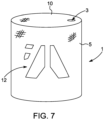
Fig. 7 shows a schematic a security barrier according to another embodiment of the invention with an individualised shape. - With reference to the
figures 1 to 5 , asecurity barrier 1 according to one embodiment of the invention is shown. In this embodiment, thesecurity barrier 1 comprises threemineral wool elements 1', 1", 1‴. As shown in the figures these three mineral wool elements have different heights and are placed adjacent each other and preferably adhered to each other at discrete spots (not shown) to form a mineral wool elements assembly. - Since the mineral wool elements are adhered to each other at discrete spots a liquid, preferably water, can flow from one
mineral wool element 1', 1", 1‴ to the other and the interior liquid volume inside acoating 5 applied to the exterior surface of themineral wool assembly 1. Thus, there is formed one common volume, which can be filled with to make the security barrier heavy and thereby very difficult to move. - The
mineral wool elements 1', 1", 1‴ preferably form a common base surface (not visible in the figures) andend surfaces 2 at opposite side of the base surface but form individualtop surfaces 10 at different distances from the base surface. - As shown in the figures the security barrier is given a stepwise increasing shape by providing the
mineral wool elements 1', 1", 1‴ in different heights. Themineral wool elements 1', 1", 1‴ may have a pore volume of at least 95 % and can therefore contain a relatively high amount of water. The mineral wool may have a binder weight fraction of 3.5 %, binder density of 1346 kg/m3 and fibre density of 2800 kg/m3. The density of themineral wool elements 1', 1", 1‴ in its dry state is 75-200 kg/m3, preferably 75-150 kg/m3, more preferably 90-120 kg/m3. To further increase the water capacity of the elements, themineral wool elements 1', 1", 1‴ are preferably hydrophilic. - The mineral wool elements for the security barrier are made of man-made vitreous fibres (MMVF) which can be glass fibres, ceramic fibres, basalt fibres, slag wool, stone wool and others, but are usually stone wool fibres, bonded with a binder. Stone wool generally has a content of iron oxide at least 3% by weight and content of alkali earth metals such as calcium oxide and magnesium oxide from 10 to 40% by weight along with the other usual oxide constituents of MMVF. These are silica; alumina; alkali metals such as sodium oxide and potassium oxide which are usually present in low amounts; and can also include titania and other minor oxides. Fibre diameter is often in the range of 2 to 10 µm, preferably 3 to 5µm. The MMVF material is in the form of a coherent mass. That is, the MMVF material is generally a coherent matrix of MMVF, which has been produced as such and formed into mineral wool elements for the security barrier.
- Normally the MMVF material for mineral wool insulation contain oil for making the products hydrophobic and prevent them from absorbing moisture. The MMVF material for the security barrier elements is however, manufactured without adding of oil to make the elements less hydrophobic, and may even be hydrophilic that it attracts water, provided water is used to fill the security barrier. The MMVF material for the elements can be hydrophilic due to the binder system used, the binder itself may be hydrophilic and/or a wetting agent is used.
- The hydrophilicity of a sample of MMVF can be measured by determining the sinking time of a sample. A sample of MMVF material having dimensions of 100x100x65mm is required for determining the sinking time. A container with a minimum size of 200x200x200mm is filled with water. The sinking time is the time from when the sample first contacts the water surface to the time when the test specimen is completely submerged. The sample is placed in contact with the water in such a way that a cross-section of 100x100mm first touches the water. The sample will then need to sink a distance of just over 65mm in order to be completely submerged. The faster the sample sinks, the more hydrophilic the sample is. The MMVF material is considered hydrophilic if the sinking time is less than 120 seconds. Preferably, the sinking time is less than 60 s. In practice, the MMVF material may have a sinking time of a few seconds, such as less than 10 seconds.
- When the binder is hydrophobic, a wetting agent is additionally included in the MMVF material in order to ensure that the material is hydrophilic. A wetting agent will increase the amount of water that the MMVF material can absorb. The use of a wetting agent in combination with a hydrophobic binder results in a hydrophilic MMVF material.
- The wetting agent used may be any of the wetting agents known for use in MMVF material that are used as growth substrates. For instance, it may be a non-ionic wetting agent such as Triton X-100 or Rewopal. Other wetting agents may be used, for instance anionic wetting agents such as linear alkyl benzene sulphonate or sodium lauryl ether sulphate (also called SLES). An example of an anionic SLES is Disponil FES27A supplied by BASF.
- The binder of the MMVF material can be hydrophilic. The hydrophilic binder does not require the use of a wetting agent. A wetting agent can nevertheless be used to increase the hydrophilicity of a hydrophilic binder in a similar manner to its action in combination with a hydrophobic binder. This means that he MMVF material will absorb a higher volume of water than if the wetting agent is not present. Any hydrophilic binder known per se can be used.
- The binder may be any binders known for use as binders for coherent MMVF products. The binder may be an aldehyde based resin such as phenol formaldehyde resin (PF), phenol urea formaldehyde resin (PUF), urea formaldehyde resin (UF), melamine formaldehyde resin (MF), melamine urea formaldehyde resin (MUF), melamine phenol formaldehyde resin (MPF), and melamine urea phenol formaldehyde resin (MUPF). This type of binder can be economically produced for use as a binder in many applications including security barrier elements.
- The binder may be a formaldehyde-free aqueous binder composition comprising: a binder component (A) obtainable by reacting at least one alkanolamine with at least one carboxylic anhydride and, optionally, treating the reaction product with a base; and a binder component (B) which comprises at least one carbohydrate, as disclosed in
WO2004/007615 . Binders of this type are hydrophilic. - Further formaldehyde-free binder compositions such as those comprising:
- a) a sugar component, and
- b) a reaction product of a polycarboxylic acid component and an alkanolamine component,
- The mineral wool elements are made by melting the raw materials in large cupola furnaces at a temperature of about 1500°C. The melt is directed onto a series of fast rotating wheels spinning (if stone wool) and formed into rock fibres with an average diameter of about 2 to 10 microns. A binding agent is added and, for hydrophilic products, an additional wetting agent can be introduced (see above). The wool is then cured in special curing ovens. Between the interconnected fibres a constant void volume is maintained, which void volume will be filled with the liquid when the security barrier is in use.
- Light mineral wool consists of air in an amount of 99% by weight and bound fibres in an amount of 1 % by weight. It follows that the heavier the product (higher density) the lower the amount of voids. The quantity of fibres in heavier mineral wool materials may be as high as 6%. With a density of 100 kg/m3, the mineral wool fibre products contain approx. 95-97% voids, where the mineral wool may have a binder weight fraction of approx. 3.5 %, binder density of approx. 1346 kg/m3 and fibre density of approx. 2800 kg/m3.
- As shown in
fig. 3 , a covering such as acoating 5 is applied, preferably by spraying. - The covering of the mineral wool elements can be made of any liquid impermeable material such as metal, polymers or the like. Depending on the choice of covering material, this can be applied by shaping, dipping (immersing) or spraying onto the surface of the mineral wool element.
- Polymer materials can be in the form of a foil, a film or a liquid coating. Especially polymeric foam coverings, such as spray foams are well suited for making an impermeable lightweight covering, which is easy and cheap to apply. By the term "spray foam" is understood a chemical product created by two materials, isocyanate and polyol resin, which react when mixed with each other and expand up to 30-60 times its liquid volume after it is sprayed in place. This expansion makes it useful as a coating material which forms to the shape of the product being coated and produces a liquid impermeable coating with high thermal insulating value and virtually no air infiltration.
- Preferred spray foams may include:
- polystyrene (PS) foam, including expanded polystyrene (EPS) and extruded polystyrene foam (XPS),
- styrofoam, or
- polyurethane (PU) foam.
- Examples of polyurethane spray foams are S-35RGB/ECO polyurethane spray from Synthesia Internacional s.I.u. or the two-component watertight membrane named MasterSeal M 689 from BASF.
- Any openings arising in a covering made of a rigid material, i.e. metal, foil or film coverings, which openings are originating from the fitting or adapting of the cover to the mineral wool elements, can be made impermeable (moisture or liquid tight) by welding or gluing or by (re-)spraying of the polymeric foam.
- As shown in
fig. 3 , the coating material may be sprayed onto the entire surface of themineral wool assembly 1 except thetop surface 10 at the highest distance from the base surface. This coating material is advantageous as it provides a liquid tight resilient seal around the surface of the mineralwool elements assembly 1. The coating material provides a rubber-like surface coating preferably of 3-5 mm in thickness so that the coating, which is animpermeable covering 5 is sufficiently strong to withstand the internal pressure of the liquid and also to provide a good protection against impacts on the exterior of the security barrier. - As can be seen in
fig. 4 , thetop surface 10 of themineral wool element 1‴ is left open so that the security barrier can be filled with water through thisopening 3. Preferably, as shown infig. 5 , there is then provided acover 4 covering thetop surface 10 at the highest distance from the base surface. - In
fig. 6 , the finished security barrier is shown. In this configuration with a security barrier in the dimensions as indicated in the example below, it is found virtually impossible to move the security barrier by a vehicle. Furthermore with a surface coating of 3-5 mm. the rubber-like coating and the mineral wool elements provide a good impact resistance and it has been found that the energy absorption capability is very good to stop projectiles and thus provides a very good barrier block and ballistic protection. -
Fig. 7 shows another embodiment, where thesecurity barrier 1 is provided with an individualised shape, in the example shown a cylinder form. The security barrier comprises a mineral wool element (not visible in the figure) which is provided with a liquidimpermeable covering 5, which is preferably a multi-layered laminate of glass fibres, such as chopped strand webs of glass fibres, which is provided on the exterior surfaces of the mineral wool element and wetted and impregnated with a resin and then left to cure. Thetop surface 10 is also covered by the laminate and withopening 3 for the filling of water into the interior of the security barrier. Several layers of glass fibre webs are provided to provide the security barrier with a resilient and impact resistant covering. An example the laminate has five layers and a thickness of 6 mm. The outermost layer is afoil 12 with printed features, such as a logo or the like. - As indicated by the
figures 2 and7 , themineral wool elements 1 may be assembled to any suitable form in order to meet any aesthetic and/or commercial requests for the public space in which the security barrier is to be utilised. - In an example, the mineral wool assembly is made of three mineral wool elements forming a step-like configuration. The dimensions are:
First element (ref. No. 1' in figs 1-3 ):600x600x2000 mm Second element (ref. No. 1" in figs 1-3 ):600x900x2000 mm Third element (ref. No. 1"' in figs 1-3 ):600x1200x2000 mm - The volumes of each of the three mineral wool elements are 0.72 m3, 1.08 m3 and 1.44 m3, respectively. This gives a total volume of 3.24 m3.
- The mineral wool elements are made with a density of 100 kg/m3. Mineral wool fibre products contain an amount of voids. With this density the mineral wool is approx. 95-97% voids. With the volume calculated above, the overall weight of the mineral wool assembly is thus 324 kg.
- The overall surface area is 15.24 m2. The mineral wool assembly is spray coated with a liquid polymer to provide watertight membrane. In an example a two-component polyurethane spray foam MasterSeal M 689 from BASF is used. The density of such polymer spray coating is typically 1.1 g/cm3. With a coating of 5 mm applied the weight of the coating is approx. 84 kg.
- This means that the total dry weight of the security barrier is approx. 408 kg.
- With a total volume of the mineral wool elements of 3.24 m3 and with a mineral wool having at least 95% voids, this means that the mineral wool assembly of the security barrier of the example is capable of absorbing up to 3,078 litres of water.
- This means that when installed on site the security barrier having a footprint on the ground of merely 3.6 m2 has a total weight of up to 3,486 kg, which is approx. 8.5 times the weight in its dry state.
Claims (23)
- A security barrier, characterised in said barrier comprising a mineral wool assembly (1) comprising at least one mineral wool element (1', 1", 1‴), having an outer liquid impermeable covering (5) and wherein the at least one mineral wool element (1', 1", 1‴) is adapted for being filled with a liquid, wherein the covering (5) comprises an opening (3) for filling the security barrier with a liquid.
- A security barrier according to claim 1, wherein the security barrier is filled with a liquid, said liquid preferably being water.
- A security barrier according to claim 1 or 2, wherein the density of the at least one mineral wool element (1', 1", 1‴) in its dry state is 75-200 kg/m3, preferably 75-150 kg/m3, more preferably 90-120 kg/m3.
- A security barrier according to any one of the claims 1 to 3, wherein the at least one mineral wool element (1', 1", 1‴) comprises a wetting agent.
- A security barrier according to any one of the preceding claims, wherein a plurality of mineral wool elements (1', 1", 1‴) are provided adjacent each other.
- A security barrier according to claim 5, wherein the mineral wool elements (1', 1", 1‴) form a common base surface of the mineral wool assembly (1) with two opposite end surfaces (2) substantially perpendicular to the base surface, and wherein the top surfaces (10) of the mineral wool elements (1', 1", 1‴) are at different distances from the base surface.
- A security barrier according to any one of the preceding claims, wherein the covering (5) is a coating.
- A security barrier according to claim 7, wherein said coating is of a material selected from a group consisting of- polystyrene (PS) foam, including expanded polystyrene (EPS) and extruded polystyrene foam (XPS),- styrofoam, and- polyurethane (PU) foam.
- A security barrier according to any one of the preceding claims, wherein the liquid impermeable covering (5) is a covering foil (12) and/or fibre laminate, such as glass fibre laminate or a carbon fibre laminate, said laminate preferably having 2-8 layers, more preferably 4-6 layers, more preferably 5 layers.
- A security barrier according to claim 9, wherein the outermost layer of the fibre laminate is a covering foil (12).
- A security barrier according to claim 9 or 10, wherein the foil (12) or laminate is adhered to the mineral wool element(s) (1', 1", 1‴) by an adhesive, such as a liquid adhesive or a powder adhesive, which is insolvable by the liquid to be filled into the security barrier.
- A security barrier according to any one of claim 9 or 10, wherein the laminate is adhered to the mineral wool element(s) (1', 1", 1‴) by the resin of the fibre reinforced laminate.
- A security barrier according to any one of the preceding claims, wherein the liquid impermeable covering (5) is provided with a predetermined colour scheme, such as printings of logos or the like.
- A security barrier according to any one of the preceding claims, wherein the opening (3) for liquid filling is provided in the liquid impermeable covering (5), such as in the upper portion of the mineral wool assembly (1), for instance in the top surface thereof (10).
- A security barrier according to claim 14, wherein there is provided a liquid filling cover (4) covering the opening (3).
- A security barrier according to any one of the preceding claims, wherein a metal sheet cover is provided on one or more sides of the barrier.
- A security barrier according to any one of the preceding claims, wherein a moisture detection sensor is provided in the mineral wool assembly (1), preferably in the upper half thereof.
- A security barrier according to any one of the preceding claims, wherein a drainage arrangement, such as a hole and a plug, is provided in the outer liquid impermeable covering, wherein the covering is a coating, preferably in the vicinity of the base surface.
- A method of manufacturing a security barrier according to any of the preceding claims, said method comprising the steps of:- providing a mineral wool assembly (1) comprising at least one mineral wool element (1', 1", 1‴), and- mounting an outer liquid impermeable covering (5) around the mineral wool assembly.
- A method according to any claim 19, whereby the step of mounting an outer liquid impermeable covering (5) involves spray coating of the outer surface of the mineral wool assembly (1).
- A method according to any claim 19 or 20, whereby a plurality of mineral wool elements (1', 1", 1‴) are provided adjacent each other and adhered to each other to form the mineral wool assembly (1), and whereby the mineral wool elements (1', 1", 1 ‴) are secured to each other in discrete spots prior to the coating.
- A method of preparing a security barrier, wherein the method comprises the steps of:- positioning the security barrier manufactured by a method according to any one of claims 19 to 21, and then- filling the security barrier with a liquid, preferably water.
- Use of a security barrier according to any one of the claims 1 to 18, where the security barrier is provided in an indoor public space, such as an airport or a railway station.
Applications Claiming Priority (2)
| Application Number | Priority Date | Filing Date | Title |
|---|---|---|---|
| EP18165619 | 2018-04-04 | ||
| PCT/EP2019/058179 WO2019192955A1 (en) | 2018-04-04 | 2019-04-01 | Security barrier made of mineral wool fillable with a liquid |
Publications (2)
| Publication Number | Publication Date |
|---|---|
| EP3765674A1 EP3765674A1 (en) | 2021-01-20 |
| EP3765674B1 true EP3765674B1 (en) | 2023-12-27 |
Family
ID=61911395
Family Applications (1)
| Application Number | Title | Priority Date | Filing Date |
|---|---|---|---|
| EP19715876.9A Active EP3765674B1 (en) | 2018-04-04 | 2019-04-01 | Security barrier made of mineral wool fillable with a liquid |
Country Status (10)
| Country | Link |
|---|---|
| US (2) | US11215427B2 (en) |
| EP (1) | EP3765674B1 (en) |
| CN (1) | CN111936703B (en) |
| CO (1) | CO2020012555A2 (en) |
| DK (1) | DK3765674T3 (en) |
| EA (1) | EA039019B1 (en) |
| MX (1) | MX2020010316A (en) |
| SA (1) | SA520420229B1 (en) |
| WO (1) | WO2019192955A1 (en) |
| ZA (1) | ZA202005943B (en) |
Families Citing this family (1)
| Publication number | Priority date | Publication date | Assignee | Title |
|---|---|---|---|---|
| WO2021130178A1 (en) * | 2019-12-23 | 2021-07-01 | Rockwool International A/S | A flood defence barrier |
Citations (2)
| Publication number | Priority date | Publication date | Assignee | Title |
|---|---|---|---|---|
| EP0962399A2 (en) * | 1998-06-06 | 1999-12-08 | Deutsche Rockwool Mineralwoll-GmbH | Shrink package for plates |
| WO2002096756A1 (en) * | 2001-05-26 | 2002-12-05 | Deutsche Rockwool Mineralwoll Gmbh & Co. Ohg | Method for producing a packaging and/or transport unit for plate-shaped insulating material consisting of mineral fibres, packaging and/or transport unit, and insulating plates |
Family Cites Families (26)
| Publication number | Priority date | Publication date | Assignee | Title |
|---|---|---|---|---|
| US3567536A (en) * | 1968-02-07 | 1971-03-02 | Goodyear Tire & Rubber | Container and method of preparation |
| US3816234A (en) * | 1971-03-22 | 1974-06-11 | Burden W | Impact absorbing laminate and articles fabricated therefrom |
| US3787279A (en) * | 1972-05-22 | 1974-01-22 | Us Navy | Shock and fire attenuating fuel tank |
| US4615455A (en) * | 1985-11-04 | 1986-10-07 | Tansill Horace A | Explosion-resistant fuel tank device |
| ES2154833T3 (en) | 1995-08-30 | 2001-04-16 | Rockwool Int | HYDROPHYL SUBSTRATE FOR GROWTH OF PLANTS, WHICH INCLUDES A FURAN RESIN. |
| US6237793B1 (en) * | 1998-09-25 | 2001-05-29 | Century Aero Products International, Inc. | Explosion resistant aircraft cargo container |
| AUPR336701A0 (en) * | 2001-02-27 | 2001-03-22 | Zurhaar, Armand | Bullet resistant glass panel |
| EP1382642A1 (en) | 2002-07-15 | 2004-01-21 | Rockwool International A/S | Formaldehyde-free aqueous binder composition for mineral fibers |
| US20040076468A1 (en) | 2002-10-18 | 2004-04-22 | Mckay Michael Donald | Security barrier and method to utilize the same |
| US6951434B2 (en) * | 2003-01-21 | 2005-10-04 | Yodock Jr Leo J | Traffic control device |
| CA2595837A1 (en) | 2004-12-08 | 2006-08-10 | Armordynamics, Inc. | Methods and apparatus for providing ballistic protection |
| US7275888B1 (en) * | 2005-03-18 | 2007-10-02 | Off The Wall Products, Llc | Interlocking barriers |
| US20090092443A1 (en) | 2006-08-09 | 2009-04-09 | Keith Friedman | Breach resistant composite barriers |
| US9091510B2 (en) * | 2007-03-21 | 2015-07-28 | Schott Corporation | Transparent armor system and method of manufacture |
| US7921759B2 (en) | 2007-10-31 | 2011-04-12 | Armordynamics, Inc. | Apparatus for providing protection from ballistic rounds projectiles, fragments and explosives |
| US9273932B2 (en) * | 2007-12-06 | 2016-03-01 | Modumetal, Inc. | Method of manufacture of composite armor material |
| US7896182B1 (en) * | 2007-12-12 | 2011-03-01 | The United States Of America As Represented By The Secretary Of The Army | Coated-poly containers |
| US20090235813A1 (en) * | 2008-03-24 | 2009-09-24 | Arthur Henry Cashin | Ballistics Barrier |
| US7968475B2 (en) * | 2009-02-10 | 2011-06-28 | E. I. Du Pont De Nemours And Company | Fabric assembly suitable for resisting ballistic objects and method of manufacture |
| DK2809849T4 (en) * | 2012-01-30 | 2021-02-01 | Rockwool Int | A DRAIN ELEMENT |
| CN203687773U (en) * | 2013-03-13 | 2014-07-02 | 上海斯瑞科技有限公司 | Armor plate with buffer isolation layer |
| WO2015119693A2 (en) * | 2013-11-12 | 2015-08-13 | Angel Armor, Llc | Structural ballistic resistant apparatus |
| CN104048560A (en) * | 2014-06-25 | 2014-09-17 | 刘百川 | Multi-layer clad sheet plate |
| US20170175349A1 (en) * | 2015-12-21 | 2017-06-22 | MikaTek, Ltd. | Recycled Rubber Barrier |
| CN107328304B (en) * | 2017-07-01 | 2019-09-10 | 中国人民解放军63908部队 | A kind of shellproof rubber composite ceramics and preparation method thereof |
| CN107843163A (en) * | 2017-12-11 | 2018-03-27 | 四川冠腾科技有限公司 | A kind of new type explosion proof water horse |
-
2019
- 2019-04-01 EA EA202092284A patent/EA039019B1/en unknown
- 2019-04-01 MX MX2020010316A patent/MX2020010316A/en unknown
- 2019-04-01 WO PCT/EP2019/058179 patent/WO2019192955A1/en unknown
- 2019-04-01 DK DK19715876.9T patent/DK3765674T3/en active
- 2019-04-01 CN CN201980023486.1A patent/CN111936703B/en active Active
- 2019-04-01 EP EP19715876.9A patent/EP3765674B1/en active Active
-
2020
- 2020-09-25 ZA ZA2020/05943A patent/ZA202005943B/en unknown
- 2020-09-27 SA SA520420229A patent/SA520420229B1/en unknown
- 2020-10-02 US US17/062,503 patent/US11215427B2/en active Active
- 2020-10-08 CO CONC2020/0012555A patent/CO2020012555A2/en unknown
-
2021
- 2021-11-04 US US17/518,705 patent/US11604045B2/en active Active
Patent Citations (2)
| Publication number | Priority date | Publication date | Assignee | Title |
|---|---|---|---|---|
| EP0962399A2 (en) * | 1998-06-06 | 1999-12-08 | Deutsche Rockwool Mineralwoll-GmbH | Shrink package for plates |
| WO2002096756A1 (en) * | 2001-05-26 | 2002-12-05 | Deutsche Rockwool Mineralwoll Gmbh & Co. Ohg | Method for producing a packaging and/or transport unit for plate-shaped insulating material consisting of mineral fibres, packaging and/or transport unit, and insulating plates |
Also Published As
| Publication number | Publication date |
|---|---|
| EA039019B1 (en) | 2021-11-23 |
| EA202092284A1 (en) | 2021-01-21 |
| DK3765674T3 (en) | 2024-01-22 |
| US11604045B2 (en) | 2023-03-14 |
| CO2020012555A2 (en) | 2020-10-30 |
| WO2019192955A1 (en) | 2019-10-10 |
| EP3765674A1 (en) | 2021-01-20 |
| US20210025678A1 (en) | 2021-01-28 |
| CN111936703B (en) | 2022-05-10 |
| MX2020010316A (en) | 2021-01-15 |
| SA520420229B1 (en) | 2022-10-30 |
| CN111936703A (en) | 2020-11-13 |
| US20220057176A1 (en) | 2022-02-24 |
| ZA202005943B (en) | 2022-06-29 |
| US11215427B2 (en) | 2022-01-04 |
Similar Documents
| Publication | Publication Date | Title |
|---|---|---|
| US20240116270A1 (en) | Composite materials and uses thereof | |
| EP2714359B1 (en) | Composite materials and uses thereof | |
| KR20160006266A (en) | Method of forming composite products by pressure, related products and apparatus | |
| US11604045B2 (en) | Security barrier for providing protection in public space | |
| KR101942986B1 (en) | External insulation and waterproofing integral concrete structure using integral concrete type organic and inorganic hybrid water proofing compound and insulation material and the construction method thereof | |
| RU2629183C2 (en) | Manufacturing method of concrete construction, premanufactured element of concrete construction, as well as concrete construction | |
| GB2491415A (en) | Triangular modular building | |
| US20150101276A1 (en) | Exterior insulation and thermal insulation composite area, as well as wall structure, comprising the composite thermal insulation or thermal insulation composite and complex process for the production of wall structures | |
| KR100422159B1 (en) | Lightweight concavo-convex finishing block for construction | |
| CA2929736C (en) | Method for producing a multilayer molded body, and multilayer molded body for the heat insulation of buildings | |
| KR100263183B1 (en) | Composite pannel manufacturing method for construction | |
| CN106013476B (en) | A kind of freezer wall | |
| KR101684629B1 (en) | Sheet of double protective coating waterproof layer and waterproof construction meohod using the same | |
| DK2678490T3 (en) | SUSTAINABLE OR CARRIING LIGHT WEIGHT ELEMENT | |
| CN207829237U (en) | The in-situ concrete wall of wood cement board composite heat-insulating layer permanence template with ribbing | |
| EP2386697A2 (en) | Thermal insulation panels, thermal insulation systems comprising such thermal insulation panels and method for producing such thermal insulation panels | |
| KR200261744Y1 (en) | Light weight prominence and depression beauty treatment block for construction | |
| JPH08246666A (en) | Reinforcing method for composite plate material, and composite plate material and form material reinforced therewith | |
| KR100809956B1 (en) | Boundary member between roadway and footway using composite material | |
| EP0268658A1 (en) | Eps combination foam piece, procedure for its manufacturing, and its use | |
| WO2004089847A1 (en) | Fire-insulating wall covering and a preparation method for same |
Legal Events
| Date | Code | Title | Description |
|---|---|---|---|
| STAA | Information on the status of an ep patent application or granted ep patent |
Free format text: STATUS: UNKNOWN |
|
| STAA | Information on the status of an ep patent application or granted ep patent |
Free format text: STATUS: THE INTERNATIONAL PUBLICATION HAS BEEN MADE |
|
| PUAI | Public reference made under article 153(3) epc to a published international application that has entered the european phase |
Free format text: ORIGINAL CODE: 0009012 |
|
| STAA | Information on the status of an ep patent application or granted ep patent |
Free format text: STATUS: REQUEST FOR EXAMINATION WAS MADE |
|
| 17P | Request for examination filed |
Effective date: 20201014 |
|
| AK | Designated contracting states |
Kind code of ref document: A1 Designated state(s): AL AT BE BG CH CY CZ DE DK EE ES FI FR GB GR HR HU IE IS IT LI LT LU LV MC MK MT NL NO PL PT RO RS SE SI SK SM TR |
|
| AX | Request for extension of the european patent |
Extension state: BA ME |
|
| DAV | Request for validation of the european patent (deleted) | ||
| DAX | Request for extension of the european patent (deleted) | ||
| GRAP | Despatch of communication of intention to grant a patent |
Free format text: ORIGINAL CODE: EPIDOSNIGR1 |
|
| STAA | Information on the status of an ep patent application or granted ep patent |
Free format text: STATUS: GRANT OF PATENT IS INTENDED |
|
| RAP3 | Party data changed (applicant data changed or rights of an application transferred) |
Owner name: ROCKWOOL A/S |
|
| GRAJ | Information related to disapproval of communication of intention to grant by the applicant or resumption of examination proceedings by the epo deleted |
Free format text: ORIGINAL CODE: EPIDOSDIGR1 |
|
| STAA | Information on the status of an ep patent application or granted ep patent |
Free format text: STATUS: REQUEST FOR EXAMINATION WAS MADE |
|
| INTG | Intention to grant announced |
Effective date: 20220608 |
|
| GRAP | Despatch of communication of intention to grant a patent |
Free format text: ORIGINAL CODE: EPIDOSNIGR1 |
|
| STAA | Information on the status of an ep patent application or granted ep patent |
Free format text: STATUS: GRANT OF PATENT IS INTENDED |
|
| INTC | Intention to grant announced (deleted) | ||
| RIN1 | Information on inventor provided before grant (corrected) |
Inventor name: EMBORG, MICHAEEL |
|
| INTG | Intention to grant announced |
Effective date: 20220728 |
|
| GRAJ | Information related to disapproval of communication of intention to grant by the applicant or resumption of examination proceedings by the epo deleted |
Free format text: ORIGINAL CODE: EPIDOSDIGR1 |
|
| STAA | Information on the status of an ep patent application or granted ep patent |
Free format text: STATUS: REQUEST FOR EXAMINATION WAS MADE |
|
| INTC | Intention to grant announced (deleted) | ||
| STAA | Information on the status of an ep patent application or granted ep patent |
Free format text: STATUS: EXAMINATION IS IN PROGRESS |
|
| 17Q | First examination report despatched |
Effective date: 20221216 |
|
| GRAP | Despatch of communication of intention to grant a patent |
Free format text: ORIGINAL CODE: EPIDOSNIGR1 |
|
| STAA | Information on the status of an ep patent application or granted ep patent |
Free format text: STATUS: GRANT OF PATENT IS INTENDED |
|
| INTG | Intention to grant announced |
Effective date: 20230719 |
|
| GRAS | Grant fee paid |
Free format text: ORIGINAL CODE: EPIDOSNIGR3 |
|
| GRAA | (expected) grant |
Free format text: ORIGINAL CODE: 0009210 |
|
| STAA | Information on the status of an ep patent application or granted ep patent |
Free format text: STATUS: THE PATENT HAS BEEN GRANTED |
|
| AK | Designated contracting states |
Kind code of ref document: B1 Designated state(s): AL AT BE BG CH CY CZ DE DK EE ES FI FR GB GR HR HU IE IS IT LI LT LU LV MC MK MT NL NO PL PT RO RS SE SI SK SM TR |
|
| REG | Reference to a national code |
Ref country code: GB Ref legal event code: FG4D |
|
| REG | Reference to a national code |
Ref country code: CH Ref legal event code: EP |
|
| REG | Reference to a national code |
Ref country code: DE Ref legal event code: R096 Ref document number: 602019043984 Country of ref document: DE |
|
| REG | Reference to a national code |
Ref country code: IE Ref legal event code: FG4D |
|
| REG | Reference to a national code |
Ref country code: DK Ref legal event code: T3 Effective date: 20240115 |
|
| REG | Reference to a national code |
Ref country code: NL Ref legal event code: FP |
|
| PG25 | Lapsed in a contracting state [announced via postgrant information from national office to epo] |
Ref country code: GR Free format text: LAPSE BECAUSE OF FAILURE TO SUBMIT A TRANSLATION OF THE DESCRIPTION OR TO PAY THE FEE WITHIN THE PRESCRIBED TIME-LIMIT Effective date: 20240328 |
|
| REG | Reference to a national code |
Ref country code: LT Ref legal event code: MG9D |
|
| PG25 | Lapsed in a contracting state [announced via postgrant information from national office to epo] |
Ref country code: LT Free format text: LAPSE BECAUSE OF FAILURE TO SUBMIT A TRANSLATION OF THE DESCRIPTION OR TO PAY THE FEE WITHIN THE PRESCRIBED TIME-LIMIT Effective date: 20231227 |
|
| PG25 | Lapsed in a contracting state [announced via postgrant information from national office to epo] |
Ref country code: ES Free format text: LAPSE BECAUSE OF FAILURE TO SUBMIT A TRANSLATION OF THE DESCRIPTION OR TO PAY THE FEE WITHIN THE PRESCRIBED TIME-LIMIT Effective date: 20231227 |
|
| PG25 | Lapsed in a contracting state [announced via postgrant information from national office to epo] |
Ref country code: LT Free format text: LAPSE BECAUSE OF FAILURE TO SUBMIT A TRANSLATION OF THE DESCRIPTION OR TO PAY THE FEE WITHIN THE PRESCRIBED TIME-LIMIT Effective date: 20231227 Ref country code: GR Free format text: LAPSE BECAUSE OF FAILURE TO SUBMIT A TRANSLATION OF THE DESCRIPTION OR TO PAY THE FEE WITHIN THE PRESCRIBED TIME-LIMIT Effective date: 20240328 Ref country code: FI Free format text: LAPSE BECAUSE OF FAILURE TO SUBMIT A TRANSLATION OF THE DESCRIPTION OR TO PAY THE FEE WITHIN THE PRESCRIBED TIME-LIMIT Effective date: 20231227 Ref country code: ES Free format text: LAPSE BECAUSE OF FAILURE TO SUBMIT A TRANSLATION OF THE DESCRIPTION OR TO PAY THE FEE WITHIN THE PRESCRIBED TIME-LIMIT Effective date: 20231227 Ref country code: BG Free format text: LAPSE BECAUSE OF FAILURE TO SUBMIT A TRANSLATION OF THE DESCRIPTION OR TO PAY THE FEE WITHIN THE PRESCRIBED TIME-LIMIT Effective date: 20240327 |
|
| REG | Reference to a national code |
Ref country code: AT Ref legal event code: MK05 Ref document number: 1644613 Country of ref document: AT Kind code of ref document: T Effective date: 20231227 |
|
| PGFP | Annual fee paid to national office [announced via postgrant information from national office to epo] |
Ref country code: NL Payment date: 20240426 Year of fee payment: 6 |