EP3764349B1 - Noise controlling method and system - Google Patents
Noise controlling method and system Download PDFInfo
- Publication number
- EP3764349B1 EP3764349B1 EP19185741.6A EP19185741A EP3764349B1 EP 3764349 B1 EP3764349 B1 EP 3764349B1 EP 19185741 A EP19185741 A EP 19185741A EP 3764349 B1 EP3764349 B1 EP 3764349B1
- Authority
- EP
- European Patent Office
- Prior art keywords
- subband
- signal
- reference signal
- subset
- subbands
- Prior art date
- Legal status (The legal status is an assumption and is not a legal conclusion. Google has not performed a legal analysis and makes no representation as to the accuracy of the status listed.)
- Active
Links
- 238000000034 method Methods 0.000 title claims description 106
- 230000003044 adaptive effect Effects 0.000 claims description 124
- 238000001914 filtration Methods 0.000 claims description 40
- 230000001143 conditioned effect Effects 0.000 claims description 28
- 230000003750 conditioning effect Effects 0.000 claims description 11
- 238000005457 optimization Methods 0.000 claims description 7
- 230000004044 response Effects 0.000 claims description 7
- 230000008569 process Effects 0.000 claims description 6
- 230000006870 function Effects 0.000 description 43
- 239000006237 Intermediate SAF Substances 0.000 description 22
- 235000015429 Mirabilis expansa Nutrition 0.000 description 18
- 244000294411 Mirabilis expansa Species 0.000 description 18
- 235000013536 miso Nutrition 0.000 description 18
- 230000009467 reduction Effects 0.000 description 17
- 238000010586 diagram Methods 0.000 description 13
- 239000011159 matrix material Substances 0.000 description 13
- 238000005259 measurement Methods 0.000 description 9
- 238000012545 processing Methods 0.000 description 8
- 230000009021 linear effect Effects 0.000 description 7
- 238000012546 transfer Methods 0.000 description 7
- 230000005284 excitation Effects 0.000 description 6
- 238000001228 spectrum Methods 0.000 description 5
- 230000003247 decreasing effect Effects 0.000 description 4
- 230000001419 dependent effect Effects 0.000 description 3
- 238000000354 decomposition reaction Methods 0.000 description 2
- 230000003993 interaction Effects 0.000 description 2
- 238000011835 investigation Methods 0.000 description 2
- 230000005236 sound signal Effects 0.000 description 2
- 230000005540 biological transmission Effects 0.000 description 1
- 230000015572 biosynthetic process Effects 0.000 description 1
- 238000012937 correction Methods 0.000 description 1
- 230000000694 effects Effects 0.000 description 1
- 238000009472 formulation Methods 0.000 description 1
- 230000007274 generation of a signal involved in cell-cell signaling Effects 0.000 description 1
- 238000010801 machine learning Methods 0.000 description 1
- 239000000203 mixture Substances 0.000 description 1
- 238000005316 response function Methods 0.000 description 1
- 230000003595 spectral effect Effects 0.000 description 1
- 238000003786 synthesis reaction Methods 0.000 description 1
Images


Classifications
-
- G—PHYSICS
- G10—MUSICAL INSTRUMENTS; ACOUSTICS
- G10K—SOUND-PRODUCING DEVICES; METHODS OR DEVICES FOR PROTECTING AGAINST, OR FOR DAMPING, NOISE OR OTHER ACOUSTIC WAVES IN GENERAL; ACOUSTICS NOT OTHERWISE PROVIDED FOR
- G10K11/00—Methods or devices for transmitting, conducting or directing sound in general; Methods or devices for protecting against, or for damping, noise or other acoustic waves in general
- G10K11/16—Methods or devices for protecting against, or for damping, noise or other acoustic waves in general
- G10K11/175—Methods or devices for protecting against, or for damping, noise or other acoustic waves in general using interference effects; Masking sound
- G10K11/178—Methods or devices for protecting against, or for damping, noise or other acoustic waves in general using interference effects; Masking sound by electro-acoustically regenerating the original acoustic waves in anti-phase
- G10K11/1785—Methods, e.g. algorithms; Devices
- G10K11/17853—Methods, e.g. algorithms; Devices of the filter
- G10K11/17854—Methods, e.g. algorithms; Devices of the filter the filter being an adaptive filter
-
- G—PHYSICS
- G10—MUSICAL INSTRUMENTS; ACOUSTICS
- G10K—SOUND-PRODUCING DEVICES; METHODS OR DEVICES FOR PROTECTING AGAINST, OR FOR DAMPING, NOISE OR OTHER ACOUSTIC WAVES IN GENERAL; ACOUSTICS NOT OTHERWISE PROVIDED FOR
- G10K11/00—Methods or devices for transmitting, conducting or directing sound in general; Methods or devices for protecting against, or for damping, noise or other acoustic waves in general
- G10K11/16—Methods or devices for protecting against, or for damping, noise or other acoustic waves in general
- G10K11/175—Methods or devices for protecting against, or for damping, noise or other acoustic waves in general using interference effects; Masking sound
- G10K11/178—Methods or devices for protecting against, or for damping, noise or other acoustic waves in general using interference effects; Masking sound by electro-acoustically regenerating the original acoustic waves in anti-phase
- G10K11/1781—Methods or devices for protecting against, or for damping, noise or other acoustic waves in general using interference effects; Masking sound by electro-acoustically regenerating the original acoustic waves in anti-phase characterised by the analysis of input or output signals, e.g. frequency range, modes, transfer functions
- G10K11/17821—Methods or devices for protecting against, or for damping, noise or other acoustic waves in general using interference effects; Masking sound by electro-acoustically regenerating the original acoustic waves in anti-phase characterised by the analysis of input or output signals, e.g. frequency range, modes, transfer functions characterised by the analysis of the input signals only
-
- G—PHYSICS
- G10—MUSICAL INSTRUMENTS; ACOUSTICS
- G10K—SOUND-PRODUCING DEVICES; METHODS OR DEVICES FOR PROTECTING AGAINST, OR FOR DAMPING, NOISE OR OTHER ACOUSTIC WAVES IN GENERAL; ACOUSTICS NOT OTHERWISE PROVIDED FOR
- G10K11/00—Methods or devices for transmitting, conducting or directing sound in general; Methods or devices for protecting against, or for damping, noise or other acoustic waves in general
- G10K11/16—Methods or devices for protecting against, or for damping, noise or other acoustic waves in general
- G10K11/175—Methods or devices for protecting against, or for damping, noise or other acoustic waves in general using interference effects; Masking sound
- G10K11/178—Methods or devices for protecting against, or for damping, noise or other acoustic waves in general using interference effects; Masking sound by electro-acoustically regenerating the original acoustic waves in anti-phase
- G10K11/1785—Methods, e.g. algorithms; Devices
- G10K11/17855—Methods, e.g. algorithms; Devices for improving speed or power requirements
-
- G—PHYSICS
- G10—MUSICAL INSTRUMENTS; ACOUSTICS
- G10K—SOUND-PRODUCING DEVICES; METHODS OR DEVICES FOR PROTECTING AGAINST, OR FOR DAMPING, NOISE OR OTHER ACOUSTIC WAVES IN GENERAL; ACOUSTICS NOT OTHERWISE PROVIDED FOR
- G10K11/00—Methods or devices for transmitting, conducting or directing sound in general; Methods or devices for protecting against, or for damping, noise or other acoustic waves in general
- G10K11/16—Methods or devices for protecting against, or for damping, noise or other acoustic waves in general
- G10K11/175—Methods or devices for protecting against, or for damping, noise or other acoustic waves in general using interference effects; Masking sound
- G10K11/178—Methods or devices for protecting against, or for damping, noise or other acoustic waves in general using interference effects; Masking sound by electro-acoustically regenerating the original acoustic waves in anti-phase
- G10K11/1787—General system configurations
- G10K11/17879—General system configurations using both a reference signal and an error signal
- G10K11/17881—General system configurations using both a reference signal and an error signal the reference signal being an acoustic signal, e.g. recorded with a microphone
-
- G—PHYSICS
- G10—MUSICAL INSTRUMENTS; ACOUSTICS
- G10K—SOUND-PRODUCING DEVICES; METHODS OR DEVICES FOR PROTECTING AGAINST, OR FOR DAMPING, NOISE OR OTHER ACOUSTIC WAVES IN GENERAL; ACOUSTICS NOT OTHERWISE PROVIDED FOR
- G10K11/00—Methods or devices for transmitting, conducting or directing sound in general; Methods or devices for protecting against, or for damping, noise or other acoustic waves in general
- G10K11/16—Methods or devices for protecting against, or for damping, noise or other acoustic waves in general
- G10K11/175—Methods or devices for protecting against, or for damping, noise or other acoustic waves in general using interference effects; Masking sound
- G10K11/178—Methods or devices for protecting against, or for damping, noise or other acoustic waves in general using interference effects; Masking sound by electro-acoustically regenerating the original acoustic waves in anti-phase
- G10K11/1787—General system configurations
- G10K11/17879—General system configurations using both a reference signal and an error signal
- G10K11/17883—General system configurations using both a reference signal and an error signal the reference signal being derived from a machine operating condition, e.g. engine RPM or vehicle speed
-
- G—PHYSICS
- G10—MUSICAL INSTRUMENTS; ACOUSTICS
- G10K—SOUND-PRODUCING DEVICES; METHODS OR DEVICES FOR PROTECTING AGAINST, OR FOR DAMPING, NOISE OR OTHER ACOUSTIC WAVES IN GENERAL; ACOUSTICS NOT OTHERWISE PROVIDED FOR
- G10K2210/00—Details of active noise control [ANC] covered by G10K11/178 but not provided for in any of its subgroups
- G10K2210/10—Applications
- G10K2210/128—Vehicles
- G10K2210/1282—Automobiles
- G10K2210/12821—Rolling noise; Wind and body noise
-
- G—PHYSICS
- G10—MUSICAL INSTRUMENTS; ACOUSTICS
- G10K—SOUND-PRODUCING DEVICES; METHODS OR DEVICES FOR PROTECTING AGAINST, OR FOR DAMPING, NOISE OR OTHER ACOUSTIC WAVES IN GENERAL; ACOUSTICS NOT OTHERWISE PROVIDED FOR
- G10K2210/00—Details of active noise control [ANC] covered by G10K11/178 but not provided for in any of its subgroups
- G10K2210/30—Means
- G10K2210/301—Computational
- G10K2210/3028—Filtering, e.g. Kalman filters or special analogue or digital filters
-
- G—PHYSICS
- G10—MUSICAL INSTRUMENTS; ACOUSTICS
- G10K—SOUND-PRODUCING DEVICES; METHODS OR DEVICES FOR PROTECTING AGAINST, OR FOR DAMPING, NOISE OR OTHER ACOUSTIC WAVES IN GENERAL; ACOUSTICS NOT OTHERWISE PROVIDED FOR
- G10K2210/00—Details of active noise control [ANC] covered by G10K11/178 but not provided for in any of its subgroups
- G10K2210/30—Means
- G10K2210/301—Computational
- G10K2210/3053—Speeding up computation or convergence, or decreasing the computational load
Definitions
- the present document relates to a noise controlling method and system.
- a noise controlling method and system implemented by a subband adaptive active noise control, ANC, system for a vehicle.
- the feedforward control systems typically involve i) one or several reference sensor(s) for detecting and/or measuring primary noises at noise sources; ii) one or several sound source(s), also known as secondary sound sources, e.g. loudspeakers of an existing audio system, for generating secondary noises to cancel the primary noises; iii) one or several error sensor(s) for detecting and/or measuring error signals representing a superposition of the primary noise and the secondary noise at different positions within an acoustic cavity, e.g., a vehicle cockpit; and iv) a control circuit, typically a digital signal processor (DSP) for performing an algorithm to generate control signals, such that the sound source(s) may be driven by the control signals to generate the secondary noises for cancelling the primary noises.
- DSP digital signal processor
- the control signals are generated by filtering the reference signals generated by the reference sensor(s) with adaptive filters, which are updated by an adaptive algorithm, typically a least mean square (LMS) algorithm, to reduce a superposition of the primary and the secondary noises detected and/or measured by the error sensor(s), i.e. to reduce the error signal, or a squared pressure of a sound signal at the position of the error sensor(s).
- an adaptive algorithm typically a least mean square (LMS) algorithm
- an amount of noise reduction within the acoustic cavity is limited by a multiple coherence between the reference signals and the sound field in the cavity.
- the multiple coherence is a measure of the degree of linearity between several inputs, i.e. the reference signals generated by the reference sensors, and an output, i.e. a sound signal at a position, such as a position close to a passenger's ear or head. It is a measure of how well the reference signals characterise the noise within the cavity.
- the ANC and/or ARNC systems usually need more than one reference signal to achieve a high coherence, and thus, to achieve a high noise reduction.
- the convergence speed may be degraded as the convergence speed of, e.g., a filtered least mean square, FXLMS, algorithm for a multiple inputs multiple outputs, MIMO, system, will be strongly affected by the eigenvalue spread of the autocorrelation matrix of the filtered inputs, i.e. the reference signals. That is, the larger the number of the reference signals in the system, the larger the size of the autocorrelation matrix, and consequently, a likelihood of a larger eigenvalue spread.
- FXLMS filtered least mean square
- an increased number of reference signals allows for a lower converged sound level in the car, which is desired.
- the increased number of reference signals not only increases the cost of the system, but also may cause a slower converge speed, which prevents a full convergence of the algorithm for a constantly changing noise environment, such as a road excitation.
- a noise controlling method comprising: generating one reference signal representing a primary noise; generating one secondary noise in response to a control signal, for cancelling the primary noise; generating one error signal representing a superposition of the primary noise and the secondary noise at a position.
- the method further comprises: generating at least one additional reference signal, and/or at least one additional secondary noise, and/or at least one additional error signal; and generating the control signal(s) for generating the secondary noise(s), by executing an adaptive subband filtering algorithm based on the reference signal(s) and the error signal(s); wherein the step of generating the control signal(s) comprises: decomposing the reference signal(s) and the error signal(s) into subband reference signal(s) and subband error signal(s), respectively, for each subband of a plurality of subbands; updating a subset of one or more subband adaptive filters for at least one subband of the plurality of subbands, based on a subset of the subband reference signal(s) of the at least one subband and a subset of the subband error signal(s) of the at least one subband, wherein at least one of said three subsets is a proper subset; updating at least one fullband adaptive filter based on the updated subband adaptive filter(s); generating the
- the step of generating at least one additional reference signal may refer to generating, e.g., by one or more reference sensors, one or more additional reference signals representing one or more different primary noises, respectively.
- the step of generating at least one additional secondary noise may refer to generating, e.g., by one or more sound sources, one or more additional secondary noises in response to one or more different control signals, respectively.
- the step of generating at least one additional error signal may refer to generating, e.g., by one or more error sensors, one or more additional error signals representing a superposition of the primary noise(s) and the secondary noise(s) at one or more different positions, respectively.
- the inventive concept is to use only a part of the available resources for performing the adaptive subband active noise control. That is, for example, only some of rather than all of the plurality of subband reference signals may be used for updating the subband adaptive filter. Alternatively or in combination, only some of rather than all of the subband error signals may be used for updating the subband adaptive filter. Alternatively or in combination, only some of rather than all of the subband adaptive filters may be updated. Consequently, only some of the reference sensors of the system, and/or only some of the error sensors of the system, and/or only some of the sound sources of the system may be active for cancelling a certain noise.
- the noise control method may also be implemented by a simpler and less costly processor.
- An adaptive subband filtering algorithm is known to be implemented by the ANC or ARNC system for updating the subband adaptive filters on each subband.
- the adaptive subband filtering algorithm may be a delay-less subband FXLMS algorithm.
- the subband adaptive filters may be updated based on a subset, preferably a proper subset, of the subband reference signals of the subband to which the subband adaptive filters belong, instead of based on all the subband reference signals of the subband. That is, a reduced number of subband reference signals are to be processed for the subband.
- the subband adaptive filters may be updated based on a subset, preferably a proper subset, of the subband error signals of the subband to which the subband adaptive filters belong, instead of based on all the subband error signals of the subband. That is, a reduced number of subband error signals are to be processed for the subband.
- a subset of subband reference signals and a subset of subband error signals may be used to update a subset of subband adaptive filters, wherein at least one of said three subsets is a proper subset.
- each subband adaptive filter may be associated to a respective secondary sound source for generating the secondary noise, this may be advantageous in determining which sound sources should be activated for the subband.
- the generation of the control signal is not a part of the subband signal processings.
- the control signal may be generated by filtering the reference signal with the fullband adaptive filters reconstructed based on the updated subband adaptive filters.
- the computational burden for controlling a broadband noise with the adaptive subband filtering algorithm may be reduced.
- cheaper control circuits may be used for implementing the noise controlling method in order to reduce the implementation cost.
- the subset of the subband reference signals and/or the subset of the subband error signals, used for updating the subset of the subband adaptive filters may be the subband signals, which are physically optimal in the sound field of an acoustic cavity.
- the term "physically optimal" may refer to, e.g., the subset of subband signals which are most physically relevant to the coupled modal excitations of the acoustic cavity structure.
- the subband reference signal which correlates most, i.e. having a high coherence level, to an acoustic signal at a monitored position within the acoustic cavity is considered to be physically optimal in the sound field of the acoustic cavity.
- Those subband signals which are less physically relevant to the coupled modal excitations of the acoustic cavity structure may be ignored and not be processed for controlling the broadband noise, in order to reduce the computational burden and to improve the convergence speed.
- the relationship of one set A being a "subset" of another set B is also called inclusion or sometimes containment.
- the set A is a subset of the set B means that all elements of the set A are also elements of the set B.
- a proper subset differs from the definition of subset.
- a proper subset C of the set B is a subset of the set B, which is not equal to the set B.
- the set C is a proper subset of the set B, then all elements of the set C are elements of the set B.
- the noise controlling method may be an ANC method, or an ARNC method.
- the term "decomposing” may refer to splitting a fullband signal into multiple subband signals.
- the multiple decomposed subband signals may be processed independently.
- the decomposition may be achieved via a filter bank comprising, e.g., a set of bandpass filters.
- fullband and subband may be in terms of frequency bands, or frequency ranges.
- the fullband signal may be a signal of a large frequency range
- the subband signal may be a signal of a small frequency range, being an interval of the large frequency range.
- An adaptive filter may be a system having a transfer function controlled by variable parameters and a means to adjust those parameters according to an optimization algorithm.
- fullband adaptive filter may refer to an adaptive filter adjusting fullband signals according to an optimization algorithm.
- the fullband signals here may be the reference signal, the error signal and the control signal.
- subband adaptive filter may refer to an adaptive filter adjusting subband signals according to an optimization algorithm.
- the subband signals here may be the subband reference signals and the subband error signals.
- the method may be performed within a car, truck, train, airplane, and any other acoustic cavity.
- At least one reference sensor may be provided for generating the reference signal representing the primary noise.
- the at least one reference sensor may be an accelerometer, a microphone, or a tachometer.
- At least one sound source may be provided for generating the secondary noise in response to the control signal, for cancelling the primary noise.
- the at least one sound source may be a loudspeaker, or a vibrating panel.
- At least one error sensor may be provided for generating the error signal representing a superposition of the primary noise and the secondary noise at the position.
- the at least one error sensor may be a microphone.
- the primary noise may be a road noise, a wind noise, or an engine noise.
- the plurality of subbands may consist of a number K of subbands, K being an even positive integer.
- the adaptive subband filtering algorithm may comprise a filter bank comprising a plurality of subbands, for decomposing the reference signal(s) and the error signal(s).
- the filter bank may be a Uniform Discrete Fourier Transform Modulated, UDFTM, filter bank.
- the method may further comprise: prior to the step of decomposing the reference signal(s) and the error signal(s), filtering the reference signal(s) with a secondary path model S.
- the method may further comprise: after the step of decomposing the reference signal(s) and the error signal(s), for each subband of the plurality of subbands, filtering the subband reference signal(s) with a subband secondary path model.
- the adaptive subband filtering algorithm may be a filtered-x least mean square, FXLMS, algorithm.
- the FXLMS algorithm may be delay-less.
- the subset of subband adaptive filter(s) may be updated by using a least mean square, LMS, algorithm.
- the fullband adaptive filter may be updated based on the updated subband adaptive filter(s), by a weight stacking scheme or a frequency stacking scheme.
- the method may further comprise: for the at least one subband of the plurality of subbands, determining the subset of the subband reference signal(s) and/or the subset of the subband error signal(s) by an optimization process.
- the subset of the subband reference signal(s) and/or the subset of the subband error signal(s) may be determined by the optimization process for, e.g., an optimal spatial matching of acoustic modes of the acoustic cavity for the subband.
- the subset of the subband reference signal(s) and/or the subset of the subband error signal(s) may be determined based on an operating condition of the vehicle, such as a speed range, a type of road surface, and the like.
- the different types of operating conditions may be stored in a table in a memory.
- the optimization process may be a machine learning process.
- the subset of the subband reference signal(s) and/or the subset of the subband error signal(s) may be determined based on physics of a system executing the method, such as an ANC system mounted within the vehicle.
- the method may further comprise: determining a leakage factor of the adaptive subband filtering algorithm based on a statistical property of the reference signal(s) and/or of the error signal(s).
- the introduction of a leakage factor in the LMS algorithm may be used for improving the algorithm performance regarding e.g., an ill-conditioned input signal, an algorithm stalling when the correction term is too small, an overflow due to finite-precision arithmetic, etc.
- introducing the leakage factor in the adaptive algorithm may attenuate the undesirable effects due to nonlinearities.
- the leakage factor is defined in, for example " Kuo, S. M., & Morgan, D. (1995). Active noise control systems: algorithms and DSP implementations. John Wiley & Sons, Inc ".
- the statistical property of the reference signal(s) and/or the error signal(s) may be a normalised property of the signal(s).
- the method may further comprise: determining a step size of the adaptive subband filtering algorithm based on a statistical property of the reference signal(s) and/or of the error signal(s).
- the method may further comprise for the at least one subband, selecting the subset of the subband reference signals, comprising steps in a following order:
- the output signal may be the error signal, e.g., measured by an error sensor.
- the output signal may also be any signal measured in a position, e.g., where a sound needs to be reduced.
- the position may be around, e.g., an ear or head of a driver and/or passenger within a car.
- the output signal may be generated by a sensor, e.g., an existed error sensor, or a different sensor, such as a microphone, during a calibration.
- the second position may be a position different from the position.
- the method may further comprise repeating the steps 3)- 6), until the remaining group of subband reference signals consisting of a last one subband reference signal, and selecting the last one subband reference signal.
- the method may further comprise prior to selecting the last one subband reference signal, performing steps 4) -5) for conditioning the last one subband reference signal and calculating a partial coherence value between the conditioned last one subband reference signal and the output signal.
- the method may further comprise repeating the steps 3)- 6), until the largest partial coherence value calculated at the step 5) being smaller than a threshold.
- the method may further comprise sorting the subband reference signals based on a sequence that each subband reference signal is selected, such that the subband reference signal selected at the step 2) has a highest ranking.
- the selected subset of the subband reference signals comprises at least the subband reference signal selected at the step 2).
- Y may refer to the output signal
- X i.(i-1)! may refer to a subband reference signal X i conditioned by the previously selected subband reference signal(s) X i.(i-1)!
- L iy may refer to a transfer function
- N may be a constant.
- condition may refer to manipulating or processing a signal in such a way that it meets requirements of a next stage for further processing.
- the subband reference signals may be arranged in an arbitrary order. That is, the order of the subband reference signals may not play any role in determining their contributions to the output signal.
- the method may further comprise prior to the step 1) of calculating the coherence value, arranging the subband reference signals in an arbitrary order.
- the method may further comprise prior to the step 1) of calculating the coherence value, performing an optimal least-square identification on the subband reference signals and the output single.
- a noise controlling system comprising: one reference sensor configured to generate one reference signal representing a primary noise; one sound source configured to generate one secondary noise in response to a control signal, for cancelling the primary noise; one error sensor configured to generate one error signal representing a superposition of the primary noise and the secondary noise at a position.
- the system further comprises: an additional reference sensor configured to generate an additional reference signal; and/or an additional sound source configured to generate an additional secondary noise; and/or an additional error sensor configured to generate an additional error signal; and a control circuit configured to generate the control signal(s) for generating the secondary noise(s), by executing an adaptive subband filtering algorithm based on the reference signal(s) and the error signal(s); wherein the control circuit is further configured to: decompose the reference signal(s) and the error signal(s) into subband reference signal(s) and subband error signal(s), respectively, for each subband of a plurality of subbands; update a subset of one or more subband adaptive filters for at least one subband of the plurality of subbands, based on a subset of the subband reference signal(s) of the at least one subband and a subset of the subband error signal(s) of the at least one subband, wherein at least one of said three subsets is a proper subset; update at least one fullband adaptive filter
- the plurality of subbands may consist of a number K of subbands, K being an even positive integer.
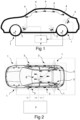
- Figs 1-2 illustrate a schematic view and a top view of a car having an ANC or ARNC system, respectively.
- the numbers of the reference sensors, the sound sources, and the error sensors shown in the figures are only illustrative examples.
- the system comprises L x reference sensors 1, L y sound sources 3, L e error sensors 4 and a control circuit 2.
- the sound sources 3 may be actuators, such as loudspeakers or vibrating surfaces, e.g., active panels.
- the error sensors 4 may be, e.g., microphones, placed within an acoustic cavity, such as a car cockpit as shown in figs 1-2 .
- the error sensors 4 may be placed closed to a driver's or passenger's ear or head.
- the reference sensors 1 may be, e.g., accelerometers, placed closed to a noise source. For example, they may be place on a car chassis around the wheels of the car, as shown in fig. 1 . Alternatively, the reference sensors 1 may be placed within the car cockpit.
- the reference sensors 1 may be any other type of sensors for characterising an excitation of an acoustic field or an excitation of a structure.
- the reference sensors 1, the error sensors 4 and sound sources 3 may be respectively connected in parallel to the control unit 2, as shown in figs 1-2 .
- the reference sensors 1, the error sensors 4, the sound sources 3 and the control circuit 2 may be connected via a wire or wirelessly.
- the control circuit 2 is shown as an entity outside the car in figs 1-2 . However, the control unit may be within the car, e.g., as a part of a vehicle system.
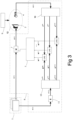
- Fig. 3 illustrates an example of a known delay-less subband FXLMS algorithm implemented in an ANC or ARNC system.
- the system comprises L x reference sensors 1, L y sound sources 3, L e error sensors 4 and an adaptive subband filtering algorithm 8 executed by a control circuit (not shown).
- the adaptive subband filtering algorithm 8 is used to generate the control signals y(n) by filtering the reference signals x(n) with adaptive filters W(n), such that the sound sources 3 may generate the secondary noises to cancel primary noise 9.
- the sound sources 3 and the error sensors 4 are provided in an acoustic propagation domain 12.
- the acoustic propagation domain 12 may be either open or closed.
- the primary noise 9 may be a road noise, generated by e.g., an interaction of a vehicle with a road through wheels.
- the primary noise 9 may also be any other type of noises, such as a wind noise or an engine noise, provided that the noise may be characterised by physically measurable reference signals.
- the adaptive filters W(n) may be updated according to any known method, such as a LMS algorithm, to reduce a superposition of the primary noise 9 and the secondary noise at the error sensors 4, i.e. to reduce the error signals e(n), or a squared pressure at the error sensors 4.
- the adaptive filters W(n) may be updated continuously.
- the adaptive subband filtering algorithm 8 in fig. 3 may be a delay-less subband FXLMS algorithm.
- delay-less refers to the fact that the control signals are generated from the reference signals in the time-domain using the fullband adaptive filters W(n) for each sample, meaning that there is no additional delay in the generation of the control signals compared to the fullband FXLMS algorithm.
- the reference signals x(n) (x 1 (n), ... , x L x (n)) may be first filtered by a secondary path model S 11, which represents a plurality of acoustic transmission paths from each of the plurality of sound sources, also known as secondary sound sources, to each of the plurality of error sensors.
- the number of secondary paths may be the number of the sound sources multiplied by the number of the error sensors, i.e. L y ⁇ L e in this example.
- the filtered reference signals x'(n) may be filtered by a filter bank 10.
- K subband signals may be generated from each of the filtered reference signals.
- each subband reference signal x' (k) contains L y ⁇ L e signals. This may result in a total L x ⁇ L y ⁇ L e subband reference signals x' (k) per subband.
- a subband reference matrix R (k) may be a matrix, wherein each coefficient is made of the subband filtered reference signals.
- ISAF may represent a length of the subband adaptive filters of the subband k .
- n may refer to a time step n.
- n-1 refers to a previous time step
- n+1 refers to a next time step.
- the error signals e(n) are also decimated by the filter bank 10, as the reference signals x(n). This results in L e subband error signals e (k) per subband.
- K 2 + 1 subbands are used.
- the others subbands may contain merely redundant information.
- the subband adaptive filters W (k) are updated by an adaptive algorithm, such as an LMS algorithm as shown in fig. 3 , based on the subband reference signals, the subband error signals.
- the control signals y ( n ) are generated from the fullband reference signals x ( n ), using the fullband adaptive filters.
- the fullband adaptive filters may be reconstructed, based on the updated subband adaptive filters by a well-known scheme 7, e.g., a weight or frequency stacking scheme.
- the filter bank 10 may be an analysis filter bank, such as a Uniform Discrete Fourier Transform Modulated, UDFTM, filter bank.
- the weight stacking scheme may be a proposed Fast Fourier Transform weight stacking scheme described in [2].
- a proper subset of the filtered subband reference signals of the subband k may be selected, e.g., by a reference signal selecting unit 5 of the control circuit (not shown).
- a proper subset of the subband error signals of the subband k may be selected, e.g., by an error signal selecting unit 6 of the control circuit.
- each subband adaptive filter may correspond to a secondary sound source for generating the secondary noise.
- a proper subset of the subband adaptive filters kmay be selected, e.g., by an adaptive filter selecting function of the control circuit (not shown).
- the reference signal selecting unit 5, the error signal selecting unit 6 and the adaptive filter selecting function may be combined as one or two selecting unit(s), or provided as three separate selecting units.
- the reference signal selecting unit 5 and the adaptive filter selecting function may be provided as one selecting unit 5.
- the superscript (k) may represent a quantity related to the subband k.
- the reference signal selecting unit 5 may comprise a function ⁇ (k) for selecting a subset, preferably a proper subset, of the L x reference sensors 1 for the subband k.
- the function ⁇ (k) may be a function defining which of the L x reference sensors are to be selected, and/or activated, for the subband k.
- the function ⁇ (k) may be predetermined. For the subband k, only the subband reference signals decomposed from the reference signals generated by the selected reference sensors are to be used.
- L x k for selecting a subset, preferably a proper subset, of the L x reference sensors 1 for the subband k.
- the function ⁇ (k) may be a function defining which of the L x reference sensors are to be selected, and/or activated, for the subband k.
- the function ⁇ (k) may be predetermined. For the subband k, only the subband reference signals decomposed from the reference signals generated by the selected reference sensors are to
- L x k may be the number of the reference sensors selected for the subband k.
- L x k may be smaller than L x . That is, L x k ⁇ L x .
- the reference signal selecting unit 5 and/or the error signal selecting unit 6 may comprise a function ⁇ (k) for selecting a subset, preferably a proper subset, of the error sensors 4 for the subband k.
- the function ⁇ (k) may be a function defining which of the L e error sensors are to be selected, and/or activated, for the subband k.
- the function ⁇ (k) may be predetermined. For the subband only the subband error signals decomposed from the error signals generated by the selected error sensors are to be used.
- L e k may be the number of the error sensors selected for the subband k.
- L e k may be smaller than L e . That is, L e k ⁇ L e .
- the adaptive filter selecting function may be a function ⁇ (k) for selecting a subset, preferably a proper subset, of the sound sources 3 for the subband k.
- the function ⁇ (k) may be a function defining which of the L y sound sources 3 are to be selected, and/or activated, for the subband k.
- the function ⁇ (k) may be predetermined. For the subband only the subband adaptive filters corresponding to these selected sound sources may be updated.
- L y k may be the number of the sound sources selected for the subband k.
- L y k may be smaller than L y . That is, L y k ⁇ L y .
- the selected subset of subband reference signals and the selected subset of subband error signals used to update the selected subset of subband adaptive filters may be selected based on the physics properties of each subband, e.g., the different frequency ranges. For example, for a subband corresponding to a low frequency range, a subband reference signal decomposed from a reference signal generated by a reference sensor for detecting a high frequency noise may not be selected for updating the subband adaptive filters of this subband.
- the functions may be used in the reference signal selecting unit 5 and/or the error signal selecting unit 6 to select a subset of the subband reference and error signals.
- the reference signal selecting unit 5 may use all three functions and to select a subset of subband reference signals.
- the subband filtered reference signals may be indexed by [reference sensor, sound source, error sensor] so all three functions may be used to select one of these indexes, in order to determine which of the subband reference signals are to be selected.
- the reference signal selecting unit 5 may use only the function for selecting the subband reference signals.
- the error signal selecting unit 6 may only use the function for selecting the subband error signals.
- ISAF may represent a length of the subband adaptive filters of the subband k.
- Each x' may represent a selected subband filtered reference signal, corresponding to the selected reference sensors ⁇ (k) ( l x ), the selected error sensors ⁇ ( k ) ( l e ) and the selected sound sources ⁇ ( k ) ( l y ).
- the secondary path models are finite impulse responses between the sound sources, i.e. the secondary sound sources, and the error sensors, mathematically represented by J coefficients.
- the subband reference matrix R (k) may have a reduced size comparing to the example of fig. 3 .
- the subband reference matrix R (k) may have a reduced size comparing to the example of fig. 3 .
- the subband reference matrix R (k) may have a reduced size comparing to the example of fig. 3 .
- only a selected subset of the subband adaptive filters may be updated for a subband.
- the fullband adaptive filters W may be reconstructed by a known weight or frequency stacking scheme 7, as shown in fig. 4 . Since only some of the subband adaptive filters may be updated on at least one subband, the reconstruction scheme 7 is performed by only using the updated subband adaptive filters. There is no need to use the non-updated subband adaptive filters for reconstructing the fullband adaptive filters, because their coefficients are useless, e.g. being zeros.
- Fig. 5 is another example of a noise controlling system.
- the example of fig. 5 differs from the examples of figs 3-4 in that the reference signals x(n) in fig. 5 are not filtered by the secondary path model S 11 before filtering by the filter bank 10. Rather, the reference signals x(n) in fig. 5 are filtered and decimated by the filter bank 10 first. This results in L x subband reference signals x (k) for each subband k.
- a subset of the subband reference signals may be selected, e.g., by the reference signal selecting unit 5 of a control circuit (not shown).
- the selected subset of the subband reference signals may be filtered by a subband secondary path model ⁇ (k) before updating the subband adaptive filters W (k) .
- the subband secondary path model are subband equivalent of the secondary path model S 11 of fig. 4 .
- the subband secondary path model ⁇ (k) may be obtained by filtering the secondary path model S 11 of fig. 4 by the filter bank 10.
- This may be advantageous as by filtering only a selected subset of subband reference signals, the computational cost may be further reduced.
- a memory with a smaller size can be used for storing the subband secondary path model ⁇ (k) , comparing to a memory for storing the secondary path model S in figs 3-4 .
- a MISO system may be used as a simplified model to describe a system comprising a plurality of inputs and a single output.
- X i ,i 1, 2, ..., i, ..., L x , represents the plurality of inputs, and Y represents the single output.
- H iy is a transfer function for representing a linear relationship between each input X i and output Y.
- N represents all possible deviations from an ideal model. That is, N represents everything that is not measured and accounted by the inputs.
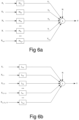
- Fig. 6a is an example of a MISO system.
- the output Y is a sum of each contribution Y i and N.
- the MISO system of fig. 6a can be equivalently represented by an ordered set of conditioned inputs, wherein each input has been conditioned by the previous inputs, as shown in fig. 6b .
- X i.(i-1)! means a conditioned input X i . That is, for each conditioned input X i , linear effects of X 1 to X i-1 have been removed, e.g., by optimum linear least-squares prediction techniques.
- the conditioned inputs X i.(i-1)! are uncorrelated to each other.
- the transfer functions L iy of fig. 6b are in general different from the H iy in fig. 6a .
- S ij is a cross-spectral density between a signal i and a signal j
- S ii is an autospectrum of the signal i.
- 1 L 12 ⁇ L 1 L x 0 1 ⁇ ⁇ ⁇ ⁇ ⁇ L L x ⁇ 1 L x 0 ... 0 1 H 1 y H 2 y ⁇ H L x y L 1 y L 2 y ⁇ L L x y
- Determining the multiple coherence ⁇ 2 may be useful in the ANC and/or ARNC systems.
- a sound reduction that can be achieved by the ANC and/or ARNC system using L x reference signals may be limited by the multiple coherence ⁇ 2 quantifying the degree of linearity between each of the reference signals and a sound measured at a position.
- the multiple coherence ⁇ 2 involving all inputs is independent on the order of the plurality of inputs X i .
- partial coherences between each input and the output are dependent on the order of the plurality of inputs X i .
- the coherence level or partial coherence level is a mathematical way to represent a relationship between a plurality of signals or data sets. For example, it may be used to estimate a power transfer between an input and an output of a linear system. It may be used to estimate a contribution of an input to an output in the MISO system.
- the inputs may be selected, and optionally sorted, by a decreased contribution to the output.
- the input which has a largest contribution to the output is the first one to be selected among the plurality of inputs.
- the input which has a least contribution to the output is the last one to be selected among the plurality of inputs. Consequently, the plurality of inputs may also be sorted in an order according to their individual contributions to the output. That is, the subset of subband reference signals, and consequently the subset of the corresponding reference signals, and the subset of the corresponding reference sensors for generating the reference signals, which contribute most to a sound in a certain frequency range may be determined.
- This may be advantageous as it may facilitate further processing based on the sorted plurality of inputs. For example, in order to save computation capacities, it is possible to only process the inputs having a coherence value larger than a threshold.
- a subset of subband reference signals i.e. a subset of reference signals, or a subset of reference sensors
- the MISO system of fig. 7 has five inputs X 1 to X 5 and one single output (not shown). However, the number of the inputs can be any positive integer.
- the five inputs may be five different fullband reference signals generated by five different reference sensors.
- the single output may be an acoustic signal measured at e.g., a location within an acoustic cavity, such as a position being close to an ear and/or head position of a driver within a car.
- the frequency range in which multiple coherence should be maximized may be a frequency range corresponding to a subband of the examples of figs 3-5 .
- the inputs X 1 to X 5 are numbered according to a final order of inputs sorted based on their respective coherence to the output, i.e. their respective contribution to the output, in the frequency range corresponding to the subband. That is, in fig. 7 , the input X 1 has a largest coherence to the output and the input X 5 has a least coherence to the output. This is only to simplify the illustration. However, the inputs may be arranged in any order.
- Step 1 The inputs X 1 to X 5 may be arranged in an arbitrary order. In fig. 7 , the inputs are arranged in this order: X 5 , X 4 ,X 1 , X 2 , X 3 .
- Step 2 A coherence value between each of the inputs X 1 to X 5 and the output is calculated.
- the input having a largest coherence value in the frequency range corresponding to the subband is selected as a first input.
- X 1 is the first input, which has the largest coherence value.
- the remaining group of inputs consists inputs X 1 to X 5 .
- Step 3 A first stage of the MISO system identification is performed, which essentially consists of conditioning the remaining group of inputs by the input selected in the step immediately prior to the present step 3, i.e. X 1 selected in step 2.
- the conditioning step may remove linear contributions L 15 ,L 14 , L 12 , L 13 of the inputs X 5 ,X 4 ,X 2 and X 3 to the output, respectively, which has already been accounted for the selected input X 1 .
- the input corresponding to a conditioned input having a largest partial coherence value in the frequency range corresponding to the subband is selected as a second input.
- X 2 is the second input, which has the largest partial coherence value among the inputs X 2 to X 5 .
- the remaining group of inputs consists inputs X 3 to X 5 .
- Step 5 A second stage of the MISO system identification is performed, which essentially consists of conditioning the remaining group of inputs by the input selected in the step immediately prior to the present step 5, i.e. X 2 selected in step 4.
- the conditioning step may remove linear contributions L 25 ,L 24 , L 23 of the inputs X 5 ,X 4 and X 3 to the output, respectively, which has already been accounted for the selected input X 2 .
- an iteration of the steps 3-4 can be performed, e.g., the steps 5-6 and the steps 7-8 are iterations of the steps 3-4.
- the remaining group of inputs are conditioned by the previously selected input, then a partial coherence between each of the remaining group of inputs and the output is calculated, and one input having a largest partial coherence value in the frequency range corresponding to the subband among the remaining group of input is selected.
- the iteration may continue until the remaining group of inputs consists of a last one input, X 5 .
- the method does not need to be performed until all the inputs are selected, as in fig. 7 . For example, if only a subset of all the input(s) that contribute most to the output is to be identified, it is sufficient to perform the method until a sufficient number of the inputs are selected. That is, the iteration may continue until a predetermined number of inputs have been selected. For example, only top three inputs having largest coherences are to be selected.
- a threshold representing a minimal partial coherence value it is possible to determine a threshold representing a minimal partial coherence value. The method can be performed until a largest partial coherence value of the remaining group of inputs is below the threshold.
- Step 9 A last stage of the MISO system identification is performed, which essentially consists of conditioning the last one input X 5 by the input selected in the step immediately prior to the present step 9, i.e. X 4 selected in step 8.
- the conditioning step may remove a linear contribution L 45 of the last one input X 5 to the output, which has already been accounted for the selected input X 4 .
- Step 10 The last one inputX 5 is selected as the last input, i.e. the fifth input in fig. 7 .
- the plurality of inputs may be sorted based on a sequence that each of the plurality of inputs is selected. Further, the plurality of inputs has been conditioned by the previously selected inputs. The first selected input, here X 1 , is not conditioned as no input has been previously selected.
- the method may be performed with an arbitrary number of inputs.
- the inputs may have an arbitrary initial order. Once the method is performed until all the inputs are selected, as shown in fig. 7 , all the inputs may be sorted by a decreased coherence, i.e. a decreased contribution, to the output. Since all the inputs, except the first selected input, are conditioned by the previously selected inputs, redundancy of information between the inputs may be reduced. That is, each input selected in the system at steps 2, 4, 6 and 8 maximally contributes to the output in terms of an added (non-redundant) information.
- the method may select, and optionally sort, the inputs, e.g., in steps 2, 4, 6, 8 and 10 of fig. 7 , before the remaining group of inputs being used in a next iteration.
- the method for selecting at least one input from a plurality of inputs of a MISO system may be implemented in many existing MISO system, or systems comprising a MISO subsystem, such as an ANC or ARNC system of figs 1-5 .
- a subset of reference sensors corresponding to the selected inputs can be selected according to the procedure of fig. 7 .
- the selected subset of reference sensors may be more important than other unselected reference sensors in noise reduction in a frequency range corresponding to the subband.
- the ANC system has L x reference sensors.
- L x k For a subband k, corresponding to a specific frequency range, a selected number L x k reference sensors may be selected by the method of fig. 7 , wherein L x k is equal to or smaller than L x . That is, L x k ⁇ L x .
- the subset of reference sensors may be defined by the function ⁇ (k) .
- the function ⁇ (k) may be defined by performing the method of fig. 7 , wherein the reference signals corresponding to the reference sensors k may be considered as the plurality of inputs of the MISO system of fig. 7 .
- the frequency range in which the coherence should be maximized may correspond to the frequency range of a subband of interest in the examples of figs 3-5 .
- the function ⁇ ( k ) can then be defined as a function that maps 1 ,2 , ... , L x k to the first L x k ordered input indexes.
- the inputs i.e. the reference signals
- the performance that the ANC system can achieve for the subband k can be directly evaluated.
- the following indexes are chosen to be as a final order of all the inputs after they are sorted, as the example in fig. 7 .
- the subband reference signals, or the reference signals or the reference sensors may be considered as the inputs of the example in fig. 7 .
- the output may be an acoustic signal measured at e.g., one location within an acoustic cavity.
- the frequency range in which multiple coherence should be maximized may be a frequency range corresponding to the subband of interest.
- L x k may be determined as the number of (subband) reference signals needed to achieve a certain level of noise reduction for a subband.
- the selection of (subband) reference signals may be performed for each subband in order to determine a subset of subband reference signals for each subband.
- the selection may be performed for only the first K 2 + 1 subbands of all the subbands.
- a subset of reference sensors corresponding to the determined subset of subband reference signals may be determined, based on a one-to-one relationship between the reference sensors and the (subband) reference signals of each subband.
- Figs 8-9 respectively illustrates four diagrams of noise reduction measurements by selecting a subset of reference sensors in an ANC system for reducing noises within a car cockpit.
- the car was moving at a speed of 40 km/h when the measurements were performed. A sound was detected at a monitor microphone 4 being closed to a driver's left ear.
- the subband reference signals are listed by a decreased contribution to the sound detected at the monitor 4. That is, the first reference signal "50:RightFrontWheel_Body_x:+X” in fig. 8 and the first reference signal “34:RightRearWheel_wisebone_z:+Z” in fig. 9 contribute most to the detected sound, respectively.
- the reference signals are named after the position and direction of the corresponding reference sensors generating the reference signals.
- the reference sensors were accelerometers placed around the different wheels on the body of the car, the wishbones, or the dampers, in a forward (+X), a lateral (+Y) or an upward (+Z) direction.
- the forward direction is the forward moving direction of the car.
- the analysis is performed on a first subband corresponding to a frequency range of 160-174 Hz.
- the analysis is performed on a second subband corresponding to a frequency range of 220-234 Hz.
- the acoustic spectra of figs 8-9 are reconstructed by selecting various numbers of subband reference signals, optimized over the respective frequency ranges, for the sound detected at monitor 4.
- the top four subband reference signals which contribute the most to the sound detected at the monitor position 4, in the first subband, i.e. 160-174 Hz, are different from those in the second subband, i.e. 220-234 Hz.
- the four most significant subband reference signals consist of reference signals generated by the reference sensors oriented in the forward (+X) and lateral (+Y) directions.
- the four most significant subband reference signals consist of reference signals generated by the reference sensors oriented in an upwards direction (+Z).
- the differences do reflect an excitation of different dominating modes.
- the dominating modes in the frequency range of 160-174 Hz are front-back and lateral modes
- the dominating modes in the frequency range of 220-234 Hz are vertical modes.
- the method may be performed for different monitors provided at different positions.
- the method may be performed to span a larger frequency range, i.e. for a plurality of subbands of interest to select a subset of the reference signals for each of these subbands.
- the reference signals and/or the subband reference signals may be ordered according to a value, e.g., an average sound level representing the sounds detected at more than one monitor positions.
- Figs 10-11 illustrate diagrams of measured SPL values.
- a sound pressure or acoustic pressure is a local pressure deviation from the ambient, average or equilibrium, atmospheric pressure, caused by a sound wave. In the air, the sound pressure can be measured using e.g., a microphone.
- the sound pressure level, SPL, or the acoustic pressure level is a logarithmic measure of the effective pressure of a sound relative to a reference value.
- Figs 10-11 illustrate different SPL values without and with an active noise control with a FXLMS algorithm for a road noise within a car.
- the algorithm is configured to control only the noise for the subbands around a resonance frequency at 160 Hz, and a resonance frequency at 230 Hz, respectively.
- the car is provided with 8 reference sensors placed around the different wheels on the body of the car, the wishbones, or the dampers, wherein 4 in a forward (X) and lateral (Y) directions, and 4 in an upward direction (Z).
- the forward direction is the forward moving direction of the car.
- 2 reference sensors are in the forward (X) direction and 2 reference sensors are in the lateral (Y) direction.
- the car is also provided with 4 sound sources for generating secondary noises, e.g., loudspeakers, and 6 error sensors, e.g., control microphones.
- 4 sound sources for generating secondary noises e.g., loudspeakers
- 6 error sensors e.g., control microphones.
- the diagrams of figs 10a-10c illustrate SPL values of without and with the active noise control by using all 8 reference sensors, by using only the 4 reference sensors in the forward and lateral directions, and by using only the 4 reference sensors in the upward direction, respectively.
- the diagrams of figs 11a-11c illustrate SPL values of without and with the active noise control by using all 8 reference sensors, by using only the 4 reference sensors in the forward and lateral directions, and by using only the 4 reference sensors in the upward direction, respectively.
- the algorithm is configured to control only the subbands corresponding to a frequency around the resonance at 160 Hz, while in figs 11a-11c the algorithm is configured to control only the subbands corresponding to a frequency around the resonance at 230 Hz.
- the function ⁇ (k) and/or ⁇ (k) for selecting a subset, preferably a proper subset, of error sensors, and a subset, preferably a proper subset, of sound sources for a subband k, respectively, may be determined by different methods.
- the function ⁇ (k) and/or ⁇ (k) for the subband k may be determined by an optimal spatial matching of a primary sound field by a secondary sound field, for a specific frequency range of the subband k.
- the sound fields within an acoustic cavity may be mainly governed by resonant acoustic modes, which are dependent on the frequency of the acoustic waves.
- the sound fields may be governed by different acoustic modes.
- the positions of the error sensors and/or sound sources may be selected to match the acoustic modes over a whole frequency range of the noise to be cancelled and different operating conditions, such as a moving speed of a car.
- Matching the acoustic modes may comprise placing the error sensors and/or sound sources somewhere outside of modal nodes.
- the modal nodes or modal lines comprise points in space where the acoustic modes, caused by standing waves, have a zero amplitude. That is, there is no signal at all at the modal nodes or modal lines. Consequently, in order to cancel the primary sound, the error sensors and/or sound sources should be preferably placed outside of these regions in space.
- the position of at least one error sensor and/or at least one sound source may be selected to match the acoustic modes for a specific frequency range corresponding to at least one subband k.
- the acoustic modes of the frequency range of the subband k may be different from the acoustic modes over the whole frequency range of the noise to be cancelled, especially at lower frequencies, where the acoustic modes are less complex, e.g., 20 to 100 Hz.
- the subband reference signals decomposed from the reference signals generated by those reference sensors which are needed for the subband k can be discarded, when processing with the subband reference signals, e.g. when updating the subband adaptive filters.
- the amount of computational operations may be reduced, and the convergence speed of the method may be improved.
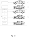
- the procedure to define the function ⁇ (k) and/or ⁇ (k) for the subband k is illustrated in fig. 12 .
- the acoustic cavity is a car cockpit in this example.
- step 1 operational measurements of a primary sound field, i.e. a disturbance sound field to be cancelled, generated for example by a road-tyres interaction, of a noise within the cockpit, are performed.
- the operational measurements may be performed during an accelerating from e.g., 0 to 130 km/h.
- the car is provided with a plurality of error sensors, represented by the black coloured microphones in fig. 12 , and a plurality of monitor sensors, represented by while coloured microphones in fig. 12 .
- the monitor sensors may be provided at positions that a sound level is to be detected and eventually to be reduced, e.g., positions being closed to a head or an ear of a driver and/or a passenger. Based on the operational measurements, the auto-spectra and cross-spectra of all the provided sensors may be determined.
- a secondary sound field i.e. a sound field generated by the secondary sound sources
- a secondary sound field may be characterized through a measurement of response functions from all sound source positions to all sensor positions, including both the error sensors and the monitor sensors.
- step 3 measured data from steps 1 and 2 is analysed to define a group of optimal positions of the error sensors and/or sound sources, for each subband k, to provide sufficient sound reductions at the monitor sensor positions for the whole frequency range of the noise.
- step 3 may be performed in a frequency domain for each subband k.
- the defined group of optimal positions of the error sensors and/or sound sources may be used to define the function(s) ⁇ (k) and/or ⁇ (k) for determining that the error sensors and/or sound sources at the optimal positions are the ones to be used for each subband k . Consequently, the subband filtered reference signals and/or subband error signals corresponding to these sound sources and/or error sensors may be selected for updating the subband adaptive filters corresponding to the selected sound sources. Subband signals corresponding to other non-selected error sensors and/or sound sources for the subband k may be discarded.
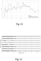
- Fig. 13 illustrates a diagram of measured SPL values when different ANC methods is performed or none ANC method is performed, i.e. ANC off.
- the SPL values in fig. 13 are measured at a position close to a front passenger's ear within a small electric car, which is provided with 8 reference sensors placed close to the wheels, 4 loudspeakers and 6 microphones. The car was moving forward at a speed of 40 km/h when measurements were performed.
- the SPL values, without any active noise control, with an active noise control method using a fullband FXLMS algorithm, with an active noise control method using a subband FXLMS algorithm with all subband reference signals used, and with an active noise control method using a subband FXLMS algorithm with a selected subset of subband reference signals for selected subbands, are presented in fig. 13 .
- the selected subset of subband reference signals is about a half of all the subband reference signals for the selected subbands.
- only the subset of the reference sensors are selected. That is, all the subband error signals are used and all the subband adaptive filters are updated for all sound sources.
- a subset of error sensors and a subset of sound sources for the subband k may be selected to further reduce the computational cost, according to the method described in fig. 12 .
- the step size of each individual subband may be adjusted based on the subband reference signals to reduce the spectral range or eigenvalue spread of the filtered reference matrix in each subband, to improve the convergence of the subband FXLMS algorithm.
- the step size is not adjusted in this example, explaining the similar performances between the fullband FXLMS and the subband FXLMS.
- Fig. 14 visualises an example the function ⁇ (k) for selecting the subset of the reference sensors to be active on each subband for the example shown in fig. 13 .
- the y-axis of fig. 14 is a reference sensor index. That is, each one of the numbers 1 to 8 refers to one of the eight reference sensors of fig. 13 .
- the x-axis of fig. 14 is a subband index. An algorithm with 128 subbands was used in this example, where all information may be considered to be contained within the first 65 subbands.
- the function ⁇ (k) for selecting a subset of the reference sensors according to fig. 13 is defined as fig. 14 .
- subband 1 the subband reference signals derived from the reference sensors 1, 2, 3, 4, 7 and 8 are selected, while the subband reference signals derived from the reference sensors 5 and 6 are not selected.
- subbands 20 and 21 For example, in subbands 20 and 21, none of the reference sensors is selected. So do the subbands 24 to 65.
- the subband adaptive filters on these subbands having no subband reference signals due to no reference sensors being selected may not be updated.
- the example ANC system used has M sound sources, L x reference sensors, L e error sensors, K subbands, I taps for fullband adaptive filters, and J taps for secondary path models.
- the decimation rate D is taken as K/4.
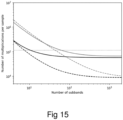
- the numbers of multiplications per sample required in each step of the proposed method and other known ANC methods are listed in Form. 1.
- the ANC method with a fullband FXLMS The ANC method with a subband FXLMS with fullband secondary path modelling
- the ANC method with a subband FXLMS with subband secondary path modelling Proposed ANC method with a subband FXLMS with subband signal selector ( fig.
- the fullband secondary path modelling means that the reference signals x(n) may be first filtered by the secondary path model S 11.
- the filtered reference signals x'(n) may then be filtered by the filter bank 10 consisting of K subbands. Then, for each subband k, the subset of the subband reference signals of the subband k may be selected.
- the subband secondary path modelling means that the reference signals x(n) are not filtered by the secondary path model S 11 before filtering by the filter bank 10. Rather, the reference signals x(n) are filtered and decimated by the filter bank 10 first. For each subband k, a subset of the subband reference signals may be selected. The selected subset of the subband reference signals may be filtered by the subband secondary path model ⁇ (k) before updating the subband adaptive filters W (k) , as in fig. 5 .
- the dotted line represents the number of multiplications per sample of the ANC method with standard fullband FXLMS.
- the upper solid line represents the number of multiplications per sample of the ANC method with subband FXLMS using fullband secondary path modelling.
- the upper dashed line represents the number of multiplications per sample of the ANC method with subband FXLMS using subband secondary path modelling.
- the lower solid line represents the number of multiplications per sample of the proposed ANC method with subband FXLMS using fullband secondary path modelling and subband signal selection, as in fig. 4 .
- the lower dashed line represents the number of multiplications per sample of the proposed ANC method with subband FXLMS using subband secondary path modelling and subband signal selection, as in fig. 5 .
- the proposed ANC method with subband FXLMS using subband secondary path modelling and subband signal selection represents a reduction in computational cost of a factor of 3.4 compared to the same algorithm without subband signal selection, and a factor 9.5 compared to the ANC method with standard fullband FXLMS algorithm.
- the computational cost may be reduced by a factor of 6 compared to the ANC method with fullband algorithm and a factor of 2.5 compared to ANC method with the standard subband algorithm.
- Additional computational cost reduction may be achieved if a subset of the error sensors and/or a subset of the sound sources to be active on each subband, respectively, are selected for updating the subband adaptive filters, e.g., by the function ⁇ (k) and/or ⁇ (k) .
- the convergence speed of the fullband delay-less subband algorithm is determined by the convergence speed of the updating algorithm in each subband.
- the convergence speed of each subband adaptive filter is governed by the Hessian matrix E[R ⁇ (k)H R (k) ], more precisely by its eigenvalue spread, defined as the ratio of the largest to the smallest eigenvalues.
- the size of the Hessian matrix may be reduced significantly.
- a faster convergence speed can be achieved by determining an optimal step size for each subband.
- a low converged level may be ensured through an optimal numbers and/or positions of the reference sensors, the sound sources and the error sensors, as well as an optimal definition of the functions ⁇ (k) , ⁇ (k) and/or ⁇ (k) , for each subband.
Landscapes
- Physics & Mathematics (AREA)
- Engineering & Computer Science (AREA)
- Acoustics & Sound (AREA)
- Multimedia (AREA)
- Soundproofing, Sound Blocking, And Sound Damping (AREA)
- Fittings On The Vehicle Exterior For Carrying Loads, And Devices For Holding Or Mounting Articles (AREA)
Description
- The present document relates to a noise controlling method and system. In particular, it relates to a noise controlling method and system implemented by a subband adaptive active noise control, ANC, system for a vehicle.
- Methods and systems for actively controlling noises, e.g., road noises, within an acoustic cavity, e.g., a vehicle, are widely studied. Such a method is often performed with the help of a feedforward control system, such as an ANC system and an Active Road Noise Control (ARNC) system.
- The feedforward control systems typically involve i) one or several reference sensor(s) for detecting and/or measuring primary noises at noise sources; ii) one or several sound source(s), also known as secondary sound sources, e.g. loudspeakers of an existing audio system, for generating secondary noises to cancel the primary noises; iii) one or several error sensor(s) for detecting and/or measuring error signals representing a superposition of the primary noise and the secondary noise at different positions within an acoustic cavity, e.g., a vehicle cockpit; and iv) a control circuit, typically a digital signal processor (DSP) for performing an algorithm to generate control signals, such that the sound source(s) may be driven by the control signals to generate the secondary noises for cancelling the primary noises. The control signals are generated by filtering the reference signals generated by the reference sensor(s) with adaptive filters, which are updated by an adaptive algorithm, typically a least mean square (LMS) algorithm, to reduce a superposition of the primary and the secondary noises detected and/or measured by the error sensor(s), i.e. to reduce the error signal, or a squared pressure of a sound signal at the position of the error sensor(s).
- Since it is known that a road noise is a broadband noise, many coefficients are needed for the adaptive filters to deal with such broadband noises. Consequently, a powerful control circuit is needed for effectively handling all the computation involved when executing the algorithm. Thus, the noise controlling method and system using such control circuit are generally expensive to implement.
- Further, it is known that an amount of noise reduction within the acoustic cavity is limited by a multiple coherence between the reference signals and the sound field in the cavity. The multiple coherence is a measure of the degree of linearity between several inputs, i.e. the reference signals generated by the reference sensors, and an output, i.e. a sound signal at a position, such as a position close to a passenger's ear or head. It is a measure of how well the reference signals characterise the noise within the cavity. Thus, the ANC and/or ARNC systems usually need more than one reference signal to achieve a high coherence, and thus, to achieve a high noise reduction.
- However, using as many as possible reference signals in the system has also disadvantages.
- Firstly, it is expensive to implement as the complexity of both hardware and software for implementing the system increases, due to the increased number of the reference signals to be processed and the increased number of computational operations when executing the algorithm for updating the adaptive filters. Further, it is also expensive as the number of the hardware for implementing the system increases, due to, e.g., the increased number of physical inputs to the control circuit.
- Secondly, the convergence speed may be degraded as the convergence speed of, e.g., a filtered least mean square, FXLMS, algorithm for a multiple inputs multiple outputs, MIMO, system, will be strongly affected by the eigenvalue spread of the autocorrelation matrix of the filtered inputs, i.e. the reference signals. That is, the larger the number of the reference signals in the system, the larger the size of the autocorrelation matrix, and consequently, a likelihood of a larger eigenvalue spread.
- Therefore, on the one hand, an increased number of reference signals allows for a lower converged sound level in the car, which is desired. On the other hand, the increased number of reference signals not only increases the cost of the system, but also may cause a slower converge speed, which prevents a full convergence of the algorithm for a constantly changing noise environment, such as a road excitation.
- Hence, there is a need to provide a noise controlling method and system, which can provide both a fast convergence speed for handling a changing noise environment, and being less expensive to implement.
- Article "An Investigation of Delayless Subband Adaptive Filtering for Multi-Input Multi-Output Active Noise Control Applications" from J. Cheer and S. Daley published in IEEE/ACM TRANSACTIONS ON AUDIO, SPEECH, AND LANGUAGE PROCESSING, VOL.25, NO.2, February 2017, discloses a MIMO noise controlling method based on subband adaptive filtering, wherein reference and error signals are decomposed into subband reference and error signals and wherein subband control filter weights are stacked in the frequency domain to form the fullband control filter.
- The invention is defined by the appended independent claims. Embodiments are set forth in the appended dependent claims, and in the following description and drawings.
- According to a first aspect, there is provided a noise controlling method, comprising: generating one reference signal representing a primary noise; generating one secondary noise in response to a control signal, for cancelling the primary noise; generating one error signal representing a superposition of the primary noise and the secondary noise at a position. The method further comprises: generating at least one additional reference signal, and/or at least one additional secondary noise, and/or at least one additional error signal; and generating the control signal(s) for generating the secondary noise(s), by executing an adaptive subband filtering algorithm based on the reference signal(s) and the error signal(s); wherein the step of generating the control signal(s) comprises: decomposing the reference signal(s) and the error signal(s) into subband reference signal(s) and subband error signal(s), respectively, for each subband of a plurality of subbands; updating a subset of one or more subband adaptive filters for at least one subband of the plurality of subbands, based on a subset of the subband reference signal(s) of the at least one subband and a subset of the subband error signal(s) of the at least one subband, wherein at least one of said three subsets is a proper subset; updating at least one fullband adaptive filter based on the updated subband adaptive filter(s); generating the control signal(s) by filtering the reference signal(s) by the updated at least one fullband adaptive filter.
- The step of generating at least one additional reference signal may refer to generating, e.g., by one or more reference sensors, one or more additional reference signals representing one or more different primary noises, respectively.
- The step of generating at least one additional secondary noise may refer to generating, e.g., by one or more sound sources, one or more additional secondary noises in response to one or more different control signals, respectively.
- The step of generating at least one additional error signal may refer to generating, e.g., by one or more error sensors, one or more additional error signals representing a superposition of the primary noise(s) and the secondary noise(s) at one or more different positions, respectively.
- The inventive concept is to use only a part of the available resources for performing the adaptive subband active noise control. That is, for example, only some of rather than all of the plurality of subband reference signals may be used for updating the subband adaptive filter. Alternatively or in combination, only some of rather than all of the subband error signals may be used for updating the subband adaptive filter. Alternatively or in combination, only some of rather than all of the subband adaptive filters may be updated. Consequently, only some of the reference sensors of the system, and/or only some of the error sensors of the system, and/or only some of the sound sources of the system may be active for cancelling a certain noise.
- By selecting the resources and/or the signals which contribute most to the noise control, and by using only the selected resources and/or signals to control the noise, a sufficient noise cancellation may be achieved, an amount of the algorithm computation may be reduced. Consequently, a faster convergence speed may be achieved for cancelling noises of a changing noise environment. The noise control method may also be implemented by a simpler and less costly processor.
- An adaptive subband filtering algorithm is known to be implemented by the ANC or ARNC system for updating the subband adaptive filters on each subband. The adaptive subband filtering algorithm may be a delay-less subband FXLMS algorithm.
- It may be advantageous as the subband adaptive filters may be updated based on a subset, preferably a proper subset, of the subband reference signals of the subband to which the subband adaptive filters belong, instead of based on all the subband reference signals of the subband. That is, a reduced number of subband reference signals are to be processed for the subband.
- The subband adaptive filters may be updated based on a subset, preferably a proper subset, of the subband error signals of the subband to which the subband adaptive filters belong, instead of based on all the subband error signals of the subband. That is, a reduced number of subband error signals are to be processed for the subband.
- Thus, it is possible to update only a subset, preferably a proper subset, of the subband adaptive filters of one subband, instead of updating all the subband adaptive filters of the subband. That is, a reduced number of subband adaptive filters are to be updated for the subband.
- That is, for one subband, a subset of subband reference signals and a subset of subband error signals may be used to update a subset of subband adaptive filters, wherein at least one of said three subsets is a proper subset. As for a subband, each subband adaptive filter may be associated to a respective secondary sound source for generating the secondary noise, this may be advantageous in determining which sound sources should be activated for the subband.
- The generation of the control signal is not a part of the subband signal processings. The control signal may be generated by filtering the reference signal with the fullband adaptive filters reconstructed based on the updated subband adaptive filters.
- By selecting only some of the available resources and/or available signals, the computational burden for controlling a broadband noise with the adaptive subband filtering algorithm may be reduced. Thus, cheaper control circuits may be used for implementing the noise controlling method in order to reduce the implementation cost.
- This may be advantageous as the convergence speed may be improved.
- The subset of the subband reference signals and/or the subset of the subband error signals, used for updating the subset of the subband adaptive filters, may be the subband signals, which are physically optimal in the sound field of an acoustic cavity. The term "physically optimal" may refer to, e.g., the subset of subband signals which are most physically relevant to the coupled modal excitations of the acoustic cavity structure. For example, the subband reference signal which correlates most, i.e. having a high coherence level, to an acoustic signal at a monitored position within the acoustic cavity is considered to be physically optimal in the sound field of the acoustic cavity. Those subband signals which are less physically relevant to the coupled modal excitations of the acoustic cavity structure may be ignored and not be processed for controlling the broadband noise, in order to reduce the computational burden and to improve the convergence speed.
- The relationship of one set A being a "subset" of another set B is also called inclusion or sometimes containment. The set A is a subset of the set B means that all elements of the set A are also elements of the set B. Thus, the set A is a subset of the set B even when the set A equals to the set B, i.e. the sets A and B have exactly same elements. For example, if B={1, 3, 5} then A={1, 3, 5} is a subset of B.
- A proper subset differs from the definition of subset. A proper subset C of the set B is a subset of the set B, which is not equal to the set B. In other words, if the set C is a proper subset of the set B, then all elements of the set C are elements of the set B. But the set B contains at least one element that is not an element of the set C. For example, if B={1 ,3,5}, then C={1} is a proper subset of B. But A={1, 3, 5} is not a proper subset of B.
- Wherein the noise controlling method may be an ANC method, or an ARNC method.
- The term "decomposing" may refer to splitting a fullband signal into multiple subband signals. The multiple decomposed subband signals may be processed independently. The decomposition may be achieved via a filter bank comprising, e.g., a set of bandpass filters. The terms fullband and subband may be in terms of frequency bands, or frequency ranges. Thus, the fullband signal may be a signal of a large frequency range, and the subband signal may be a signal of a small frequency range, being an interval of the large frequency range.
- An adaptive filter may be a system having a transfer function controlled by variable parameters and a means to adjust those parameters according to an optimization algorithm.
- The term "fullband adaptive filter" may refer to an adaptive filter adjusting fullband signals according to an optimization algorithm. The fullband signals here may be the reference signal, the error signal and the control signal.
- The term "subband adaptive filter" may refer to an adaptive filter adjusting subband signals according to an optimization algorithm. The subband signals here may be the subband reference signals and the subband error signals.
- The method may be performed within a car, truck, train, airplane, and any other acoustic cavity.
- At least one reference sensor may be provided for generating the reference signal representing the primary noise. The at least one reference sensor may be an accelerometer, a microphone, or a tachometer.
- At least one sound source may be provided for generating the secondary noise in response to the control signal, for cancelling the primary noise. The at least one sound source may be a loudspeaker, or a vibrating panel. At least one error sensor may be provided for generating the error signal representing a superposition of the primary noise and the secondary noise at the position. The at least one error sensor may be a microphone.
- The primary noise may be a road noise, a wind noise, or an engine noise.
- The plurality of subbands may consist of a number K of subbands, K being an even positive integer. The method may further comprises performing the step of updating a subset of one or more subband adaptive filters for a number t of subbands of the plurality of subbands, wherein a relationship between the numbers K and t is: t = K/2 +1.
- Out of the k subbands, only the first subbands may be updated. The
other 
- The adaptive subband filtering algorithm may comprise a filter bank comprising a plurality of subbands, for decomposing the reference signal(s) and the error signal(s).
- The filter bank may be a Uniform Discrete Fourier Transform Modulated, UDFTM, filter bank.
- The method may further comprise: prior to the step of decomposing the reference signal(s) and the error signal(s), filtering the reference signal(s) with a secondary path model S.
- The method may further comprise: after the step of decomposing the reference signal(s) and the error signal(s), for each subband of the plurality of subbands, filtering the subband reference signal(s) with a subband secondary path model.
- The adaptive subband filtering algorithm may be a filtered-x least mean square, FXLMS, algorithm.
- The FXLMS algorithm may be delay-less.
- For the at least one subband of the plurality of subbands, the subset of subband adaptive filter(s) may be updated by using a least mean square, LMS, algorithm.
- The fullband adaptive filter may be updated based on the updated subband adaptive filter(s), by a weight stacking scheme or a frequency stacking scheme.
- The method may further comprise: for the at least one subband of the plurality of subbands, determining the subset of the subband reference signal(s) and/or the subset of the subband error signal(s) by an optimization process.
- The subset of the subband reference signal(s) and/or the subset of the subband error signal(s) may be determined by the optimization process for, e.g., an optimal spatial matching of acoustic modes of the acoustic cavity for the subband.
- When the method is applied in vehicles, the subset of the subband reference signal(s) and/or the subset of the subband error signal(s) may be determined based on an operating condition of the vehicle, such as a speed range, a type of road surface, and the like.
- The different types of operating conditions may be stored in a table in a memory.
- The optimization process may be a machine learning process.
- Alternatively or in combination, the subset of the subband reference signal(s) and/or the subset of the subband error signal(s) may be determined based on physics of a system executing the method, such as an ANC system mounted within the vehicle.
- The method may further comprise: determining a leakage factor of the adaptive subband filtering algorithm based on a statistical property of the reference signal(s) and/or of the error signal(s).
- The introduction of a leakage factor in the LMS algorithm may be used for improving the algorithm performance regarding e.g., an ill-conditioned input signal, an algorithm stalling when the correction term is too small, an overflow due to finite-precision arithmetic, etc. In active noise control systems, introducing the leakage factor in the adaptive algorithm may attenuate the undesirable effects due to nonlinearities. The leakage factor is defined in, for example "Kuo, S. M., & Morgan, D. (1995). Active noise control systems: algorithms and DSP implementations. John Wiley & Sons, Inc".
- The statistical property of the reference signal(s) and/or the error signal(s) may be a normalised property of the signal(s).
- The method may further comprise: determining a step size of the adaptive subband filtering algorithm based on a statistical property of the reference signal(s) and/or of the error signal(s).
- When the method comprising generating at least one additional reference signal, the method may further comprise for the at least one subband, selecting the subset of the subband reference signals, comprising steps in a following order:
- 1) calculating a coherence value representing a coherence level at a frequency range of the at least one subband, between each of the subband reference signals and an output signal,
wherein the output signal is one of: the error signal(s) and a signal representing a sound measured at a second position; - 2) among the subband reference signals, selecting a subband reference signal having a largest coherence value;
- 3) creating a remaining group of the subband reference signals, wherein the remaining group of the subband reference signals consists all the subband reference signals except the previously selected subband reference signal(s);
- 4) for each subband reference signal of the remaining group of subband reference signals,
conditioning the subband reference signal for generating a corresponding conditioned subband reference signal; - 5) for each conditioned subband reference signal,
calculating a partial coherence value representing a coherence level at the frequency range of the at least one subband, between the conditioned subband reference signal and the output signal; - 6) among the remaining group of reference signals, selecting a subband reference signal corresponding to a conditioned subband reference signal having a largest partial coherence value.
- The output signal may be the error signal, e.g., measured by an error sensor.
- The output signal may also be any signal measured in a position, e.g., where a sound needs to be reduced. The position may be around, e.g., an ear or head of a driver and/or passenger within a car. The output signal may be generated by a sensor, e.g., an existed error sensor, or a different sensor, such as a microphone, during a calibration.
- The second position may be a position different from the position.
- The method may further comprise repeating the steps 3)- 6), until the remaining group of subband reference signals consisting of a last one subband reference signal, and selecting the last one subband reference signal.
- The method may further comprise prior to selecting the last one subband reference signal, performing steps 4) -5) for conditioning the last one subband reference signal and calculating a partial coherence value between the conditioned last one subband reference signal and the output signal.
- The method may further comprise repeating the steps 3)- 6), until the largest partial coherence value calculated at the step 5) being smaller than a threshold.
- The method may further comprise sorting the subband reference signals based on a sequence that each subband reference signal is selected, such that the subband reference signal selected at the step 2) has a highest ranking.
- The selected subset of the subband reference signals comprises at least the subband reference signal selected at the step 2).
- A relationship between the conditioned subband reference signals and the output signal may be

- The step 4) of generating the conditioned subband reference signals Xi.(i-1)!may comprise conditioning each subband reference signal of the remaining group of subband reference signals by a previously selected subband reference signal according to

- The term "conditioning" may refer to manipulating or processing a signal in such a way that it meets requirements of a next stage for further processing.
- By removing the redundancies between the subband reference signals, the subband reference signals may be arranged in an arbitrary order. That is, the order of the subband reference signals may not play any role in determining their contributions to the output signal.
- The method may further comprise prior to the step 1) of calculating the coherence value, arranging the subband reference signals in an arbitrary order.
- The method may further comprise prior to the step 1) of calculating the coherence value, performing an optimal least-square identification on the subband reference signals and the output single.
- According to a second aspect, there is provided a noise controlling system, comprising: one reference sensor configured to generate one reference signal representing a primary noise; one sound source configured to generate one secondary noise in response to a control signal, for cancelling the primary noise; one error sensor configured to generate one error signal representing a superposition of the primary noise and the secondary noise at a position. The system further comprises: an additional reference sensor configured to generate an additional reference signal; and/or an additional sound source configured to generate an additional secondary noise; and/or an additional error sensor configured to generate an additional error signal; and a control circuit configured to generate the control signal(s) for generating the secondary noise(s), by executing an adaptive subband filtering algorithm based on the reference signal(s) and the error signal(s); wherein the control circuit is further configured to: decompose the reference signal(s) and the error signal(s) into subband reference signal(s) and subband error signal(s), respectively, for each subband of a plurality of subbands; update a subset of one or more subband adaptive filters for at least one subband of the plurality of subbands, based on a subset of the subband reference signal(s) of the at least one subband and a subset of the subband error signal(s) of the at least one subband, wherein at least one of said three subsets is a proper subset; update at least one fullband adaptive filter based on the updated subband adaptive filter(s); generate the control signal(s) by filtering the reference signal(s) by the updated at least one fullband adaptive filter.
- The plurality of subbands may consist of a number K of subbands, K being an even positive integer. The control circuit may be further configured to update a subset of one or more subband adaptive filters for a number t of subbands of the plurality of subbands, wherein a relationship between the numbers K and t is: t = K/2 +1.
-
-
Fig. 1 illustrates a schematic view of a car having an ANC or ARNC system. -
Fig. 2 illustrates a top view of a car having an ANC or ARNC system. -
Fig. 3 illustrates an example of a delay-less subband FXLMS algorithm implemented in an ANC or ARNC system. -
Fig. 4 illustrates an example of a noise controlling system. -
Fig. 5 illustrates an example of a noise controlling system. -
Fig. 6a illustrates an example of a MISO system. -
Fig. 6b illustrates an equivalent of the MISO system offig. 6a . -
Fig. 7 illustrates a procedure for sorting a plurality of inputs. -
Fig. 8 illustrates four diagrams of noise reduction measurements. -
Fig. 9 illustrates four diagrams of noise reduction measurements. -
Figs 1 0a-10c illustrate diagrams of measured SPL values. -
Figs 11a-11c illustrate diagrams of measured SPL values. -
Fig. 12 illustrates an example of a method for defining the function ε(k) and/or Ψ(k). -
Fig. 13 illustrates a diagram of measured SPL values. -
Fig. 14 illustrates an example of the function χ(k). -
Fig. 15 illustrates a diagram of numbers of multiplications per sample of different ANC methods. -
Figs 1-2 illustrate a schematic view and a top view of a car having an ANC or ARNC system, respectively. The numbers of the reference sensors, the sound sources, and the error sensors shown in the figures are only illustrative examples. - In
figs 1-2 , the system comprises Lx reference sensors 1, Ly sound sources 3, Le error sensors 4 and acontrol circuit 2. - The
sound sources 3 may be actuators, such as loudspeakers or vibrating surfaces, e.g., active panels. - The
error sensors 4 may be, e.g., microphones, placed within an acoustic cavity, such as a car cockpit as shown infigs 1-2 . Theerror sensors 4 may be placed closed to a driver's or passenger's ear or head. - The
reference sensors 1 may be, e.g., accelerometers, placed closed to a noise source. For example, they may be place on a car chassis around the wheels of the car, as shown infig. 1 . Alternatively, thereference sensors 1 may be placed within the car cockpit. Thereference sensors 1 may be any other type of sensors for characterising an excitation of an acoustic field or an excitation of a structure. - The
reference sensors 1, theerror sensors 4 andsound sources 3 may be respectively connected in parallel to thecontrol unit 2, as shown infigs 1-2 . Thereference sensors 1, theerror sensors 4, thesound sources 3 and thecontrol circuit 2 may be connected via a wire or wirelessly. - The
control circuit 2 is shown as an entity outside the car infigs 1-2 . However, the control unit may be within the car, e.g., as a part of a vehicle system. -
Fig. 3 illustrates an example of a known delay-less subband FXLMS algorithm implemented in an ANC or ARNC system. - The method shown in
fig. 3 can be found in, for example, [1] Cheer, J., & Daley, S. (2017), An investigation of delayless subband adaptive filtering for multi-input multi-output active noise control applications. IEEE/ACM Transactions on Audio, Speech, and Language Processing, 25(2), 359-373 ; and [2] Milani, A. A., Panahi, I. M., & Loizou, P. C. (2009), A new delayless subband adaptive filtering algorithm for active noise control systems. IEEE transactions on audio, speech, and language processing, 17(5), 1038-1045 . - In
fig. 3 , the system comprises Lx reference sensors 1, Ly sound sources 3, Le error sensors 4 and an adaptivesubband filtering algorithm 8 executed by a control circuit (not shown). The Lx reference sensors 1 generate Lx reference signals x(n), respectively, which may be represented in a vector notation by x(n) = (x1(n), ... , xLx (n)). The Le error sensors 4 generate Le error signals e(n), respectively, which may be represented in a vector notation by e(n) = (e1(n), ... , eLe (n)). The Ly sound sources 3 are driven by Ly control signals y(n), respectively, which may be represented in a vector notation by y(n) = (y 1(n), ... , yLy (n)). - The adaptive
subband filtering algorithm 8 is used to generate the control signals y(n) by filtering the reference signals x(n) with adaptive filters W(n), such that thesound sources 3 may generate the secondary noises to cancelprimary noise 9. Thesound sources 3 and theerror sensors 4 are provided in anacoustic propagation domain 12. Theacoustic propagation domain 12 may be either open or closed. - The
primary noise 9 may be a road noise, generated by e.g., an interaction of a vehicle with a road through wheels. Theprimary noise 9 may also be any other type of noises, such as a wind noise or an engine noise, provided that the noise may be characterised by physically measurable reference signals. - The adaptive filters W(n) may be updated according to any known method, such as a LMS algorithm, to reduce a superposition of the
primary noise 9 and the secondary noise at theerror sensors 4, i.e. to reduce the error signals e(n), or a squared pressure at theerror sensors 4. The adaptive filters W(n) may be updated continuously. The adaptivesubband filtering algorithm 8 infig. 3 may be a delay-less subband FXLMS algorithm. The term delay-less refers to the fact that the control signals are generated from the reference signals in the time-domain using the fullband adaptive filters W(n) for each sample, meaning that there is no additional delay in the generation of the control signals compared to the fullband FXLMS algorithm. - The reference signals x(n) = (x1(n), ... , xL
x (n)) may be first filtered by a secondarypath model S 11, which represents a plurality of acoustic transmission paths from each of the plurality of sound sources, also known as secondary sound sources, to each of the plurality of error sensors. Thus, the number of secondary paths may be the number of the sound sources multiplied by the number of the error sensors, i.e. Ly ∗Le in this example. - The filtered reference signals x'(n) may be represented in a vector notation by x'(n) = (x1,1,1(n), ... xL
e ,1,1(n), ... , xLe ,Lx ,1(n), ... , xLe ,Lx ,Ly (n)). The filtered reference signals x'(n) may be filtered by afilter bank 10. As a consequence, K subband signals may be generated from each of the filtered reference signals. Thefilter band 10 may comprise a decimation step of a factorD,wherein
paths model S 11, which comprises Ly ∗Le secondary paths, each subband reference signal x'(k) contains Ly ∗Le signals. This may result in a total Lx ∗Ly ∗Le subband reference signals x'(k) per subband. - A subband reference matrix R (k) may be a matrix, wherein each coefficient is made of the subband filtered reference signals. The subband reference matrix R (k) for the subband k may be expressed as


- ISAF may represent a length of the subband adaptive filters of the subband k. n may refer to a time step n. For example, when n refers to a current time step, n-1 refers to a previous time step and n+1 refers to a next time step.
- The error signals e(n) are also decimated by the
filter bank 10, as the reference signals x(n). This results in Le subband error signals e(k) per subband. - Preferably, out of the K subbands created by the
filter bank 10, only thefirst 
- For each subband k of the
first 
fig. 3 , based on the subband reference signals, the subband error signals. The control signals y(n) are generated from the fullband reference signals x (n), using the fullband adaptive filters. - When the subband adaptive filter(s) W(k) of each subband k, preferably each subband of the
first 
scheme 7, e.g., a weight or frequency stacking scheme. - The
filter bank 10 may be an analysis filter bank, such as a Uniform Discrete Fourier Transform Modulated, UDFTM, filter bank. The weight stacking scheme may be a proposed Fast Fourier Transform weight stacking scheme described in [2]. - In connection with
fig. 4 , the noise controlling system according to the invention is discussed in detail. - In
fig. 4 , for each subband k, preferably of thefirst 
signal selecting unit 5 of the control circuit (not shown). For each subband k, a proper subset of the subband error signals of the subband k may be selected, e.g., by an errorsignal selecting unit 6 of the control circuit. - For each subband k , each subband adaptive filter may correspond to a secondary sound source for generating the secondary noise. For each subband k, a proper subset of the subband adaptive filters kmay be selected, e.g., by an adaptive filter selecting function of the control circuit (not shown).
- The reference
signal selecting unit 5, the errorsignal selecting unit 6 and the adaptive filter selecting function may be combined as one or two selecting unit(s), or provided as three separate selecting units. For example, the referencesignal selecting unit 5 and the adaptive filter selecting function may be provided as one selectingunit 5. - For each subband k, only the selected subset of the subband reference signals, and/or the selected subset of the subband error signals are used for updating the selected subset of subband adaptive filters W(k) wherein at least one of these three selected subsets is a proper subset, The superscript (k) may represent a quantity related to the subband k.
- The reference
signal selecting unit 5 may comprise a function χ(k) for selecting a subset, preferably a proper subset, of the Lx reference sensors 1 for the subband k. The function χ(k) may be a function defining which of the Lx reference sensors are to be selected, and/or activated, for the subband k. The function χ(k) may be predetermined. For the subband k, only the subband reference signals decomposed from the reference signals generated by the selected reference sensors are to be used.
- may be the number of the reference sensors selected for the subband k.


- The reference
signal selecting unit 5 and/or the errorsignal selecting unit 6 may comprise a function ε(k) for selecting a subset, preferably a proper subset, of theerror sensors 4 for the subband k. The function ε(k) may be a function defining which of the Le error sensors are to be selected, and/or activated, for the subband k. The function ε(k) may be predetermined. For the subband only the subband error signals decomposed from the error signals generated by the selected error sensors are to be used.


- The adaptive filter selecting function may be a function Ψ(k) for selecting a subset, preferably a proper subset, of the
sound sources 3 for the subband k. The function Ψ(k) may be a function defining which of the Ly sound sources 3 are to be selected, and/or activated, for the subband k. The function Ψ(k) may be predetermined. For the subband only the subband adaptive filters corresponding to these selected sound sources may be updated.


- The selected subset of subband reference signals and the selected subset of subband error signals used to update the selected subset of subband adaptive filters, e.g., defined respectively by the functions ε(k), Ψ(k) and χ(k), may be selected based on the physics properties of each subband, e.g., the different frequency ranges. For example, for a subband corresponding to a low frequency range, a subband reference signal decomposed from a reference signal generated by a reference sensor for detecting a high frequency noise may not be selected for updating the subband adaptive filters of this subband.
- This may allow a reduced computational cost, in addition to a potential gain in performance.
- The functions may be used in the reference
signal selecting unit 5 and/or the errorsignal selecting unit 6 to select a subset of the subband reference and error signals. For example, the referencesignal selecting unit 5 may use all three functions and to select a subset of subband reference signals. In the example offig 4 , since there is one secondary path model for each couple of a sound source and an error sensor, the subband filtered reference signals may be indexed by [reference sensor, sound source, error sensor] so all three functions may be used to select one of these indexes, in order to determine which of the subband reference signals are to be selected. - When the reference signals are decomposed to subband reference signals, and the subband reference signals are selected prior to a subband secondary path filtering, as the example of
fig. 5 , the referencesignal selecting unit 5 may use only the function for selecting the subband reference signals. The errorsignal selecting unit 6 may only use the function for selecting the subband error signals. - The selected subset of the subband error signals e(k) for the subband k may be expressed as

- The subband reference matrix R(k) for the subband k may be expressed as


- ISAF may represent a length of the subband adaptive filters of the subband k.
- Each x' may represent a selected subband filtered reference signal, corresponding to the selected reference sensors χ(k)(lx ), the selected error sensors ε (k)(le ) and the selected sound sources Ψ (k)(ly ).


- The secondary path models are finite impulse responses between the sound sources, i.e. the secondary sound sources, and the error sensors, mathematically represented by J coefficients.
- For each subband k, the subband adaptive filters W(k) may be expressed as

- Each subband adaptive filter wi (k) of the subband adaptive filters W(k) may be expressed as

- The subband adaptive filters W(k) at a time step n+1 may be updated using a known method, such as an LMS algorithm as shown in
fig. 4 , according to
- When a proper subset of the subband reference signals are selected and used for updating the subband adaptive filters for a subband, as in
fig. 4 , the subband reference matrix R(k) may have a reduced size comparing to the example offig. 3 . - Alternatively or in combination, when a proper subset of the subband error signals are selected and used for updating the subband adaptive filters for a subband, as in
fig. 4 , the subband reference matrix R (k) may have a reduced size comparing to the example offig. 3 . - Alternatively or in combination, when a proper subset of the subband adaptive filters are updated on a subband, the subband reference matrix R(k) may have a reduced size comparing to the example of
fig. 3 . - Consequently, the above formulations related to the subband reference matrix R (k) also differ from that of the example of
fig. 3 . - Further, according to the example of
fig. 4 , only a selected subset of the subband adaptive filters may be updated for a subband. - Once the selected subband adaptive filters W(k) are updated, the fullband adaptive filters W may be reconstructed by a known weight or
frequency stacking scheme 7, as shown infig. 4 . Since only some of the subband adaptive filters may be updated on at least one subband, thereconstruction scheme 7 is performed by only using the updated subband adaptive filters. There is no need to use the non-updated subband adaptive filters for reconstructing the fullband adaptive filters, because their coefficients are useless, e.g. being zeros. -
Fig. 5 is another example of a noise controlling system. - The example of
fig. 5 differs from the examples offigs 3-4 in that the reference signals x(n) infig. 5 are not filtered by the secondarypath model S 11 before filtering by thefilter bank 10. Rather, the reference signals x(n) infig. 5 are filtered and decimated by thefilter bank 10 first. This results in Lx subband reference signals x(k) for each subband k. - For each subband k, a subset of the subband reference signals may be selected, e.g., by the reference
signal selecting unit 5 of a control circuit (not shown). For each subband k, the selected subset of the subband reference signals may be filtered by a subband secondary path model Ŝ(k) before updating the subband adaptive filters W(k). - That is, in the examples of
figs 3-4 , all the reference signals x(n) are filtered by the secondary path model S. However, in the example offig. 5 , for each subband k, only the selected subband reference signals are filtered by the subband secondary path model Ŝ(k). The subband secondary path model are subband equivalent of the secondarypath model S 11 offig. 4 . For example, the subband secondary path model Ŝ(k) may be obtained by filtering the secondarypath model S 11 offig. 4 by thefilter bank 10. - This may be advantageous as by filtering only a selected subset of subband reference signals, the computational cost may be further reduced.
- Each of the subband secondary path model Ŝ(k) may be modelled with JSAF coefficients. Due to the decimation factor applied during subband filtering by the
filter bank 10, JSAF may be smaller than J. For example, JSAF may be taken as a value related to J and K, such as JSAF = 4J/K. - Further, a memory with a smaller size can be used for storing the subband secondary path model Ŝ(k), comparing to a memory for storing the secondary path model S in
figs 3-4 . - In connection with
figs 6a, 6b and7 , the procedures of the method for determining the subset of subband reference signals, and consequently subset of the corresponding (fullband) reference signals, and the subset of the corresponding reference sensors for generating the reference signals are described in detail. - A MISO system may be used as a simplified model to describe a system comprising a plurality of inputs and a single output.
- The MISO system may be represented by

- Wherein Xi,i = 1, 2, ..., i, ..., Lx, represents the plurality of inputs, and Y represents the single output. And Hiy is a transfer function for representing a linear relationship between each input Xi and output Y. N represents all possible deviations from an ideal model. That is, N represents everything that is not measured and accounted by the inputs.
-
Fig. 6a is an example of a MISO system. With the transfer function Hiy, a contribution Yi, i = 1, 2, ..., i, ..., Lx of each input Xi to the output Y can be calculated. The output Y is a sum of each contribution Yi and N. - In order to better characterise the MISO system, much studies have been done to identify the transfer function Hiy.
- The MISO system of
fig. 6a can be equivalently represented by an ordered set of conditioned inputs, wherein each input has been conditioned by the previous inputs, as shown infig. 6b . - In
fig. 6b , Xi.(i-1)! means a conditioned input Xi. That is, for each conditioned input Xi, linear effects of X1 to Xi-1 have been removed, e.g., by optimum linear least-squares prediction techniques. The conditioned inputs Xi.(i-1)! are uncorrelated to each other. The transfer functions Liy offig. 6b are in general different from the Hiy infig. 6a . - The equivalent MISO system in
fig. 6b may be represented by
- Thus, it is possible to determine Hiy and Liy by the following relationships

- where Sij is a cross-spectral density between a signal i and a signal j, and Sii is an autospectrum of the signal i.

- Thus, it is possible to decompose the MISO system into uncorrelated subsystems each comprising a single input and allows in particular the computation of multiple coherence γ2 quantifying a degree of linearity between each of the plurality of inputs Xi and the output Y. Thus, it is possible to determine which one(s) of the plurality of input Xi contribute most to the output, i.e. which one(s) of the plurality of input Xi is/are the most significant input(s).
- Determining the multiple coherence γ2 may be useful in the ANC and/or ARNC systems. For example, a sound reduction that can be achieved by the ANC and/or ARNC system using Lx reference signals may be limited by the multiple coherence γ2 quantifying the degree of linearity between each of the reference signals and a sound measured at a position. The relationship between the sound reduction ΔdBlimit and the multiple coherence γ2 can be expressed as

- The multiple coherence γ2 involving all inputs is independent on the order of the plurality of inputs Xi. However, partial coherences between each input and the output are dependent on the order of the plurality of inputs Xi.
- The coherence level or partial coherence level is a mathematical way to represent a relationship between a plurality of signals or data sets. For example, it may be used to estimate a power transfer between an input and an output of a linear system. It may be used to estimate a contribution of an input to an output in the MISO system.
- Thus, by selecting the input having a largest coherence value or a largest partial coherence value between each (conditioned) input and the single output, the inputs may be selected, and optionally sorted, by a decreased contribution to the output. The input which has a largest contribution to the output is the first one to be selected among the plurality of inputs. And the input which has a least contribution to the output is the last one to be selected among the plurality of inputs. Consequently, the plurality of inputs may also be sorted in an order according to their individual contributions to the output. That is, the subset of subband reference signals, and consequently the subset of the corresponding reference signals, and the subset of the corresponding reference sensors for generating the reference signals, which contribute most to a sound in a certain frequency range may be determined.
- This may be advantageous as it may facilitate further processing based on the sorted plurality of inputs. For example, in order to save computation capacities, it is possible to only process the inputs having a coherence value larger than a threshold.
- In connection with
fig. 7 , the steps for selecting a subset of subband reference signals (i.e. a subset of reference signals, or a subset of reference sensors) are discussed in detail. - The MISO system of
fig. 7 has five inputs X1 to X5 and one single output (not shown). However, the number of the inputs can be any positive integer. The five inputs may be five different fullband reference signals generated by five different reference sensors. The single output may be an acoustic signal measured at e.g., a location within an acoustic cavity, such as a position being close to an ear and/or head position of a driver within a car. The frequency range in which multiple coherence should be maximized may be a frequency range corresponding to a subband of the examples offigs 3-5 . - In
fig. 7 , the inputs X1 to X5 are numbered according to a final order of inputs sorted based on their respective coherence to the output, i.e. their respective contribution to the output, in the frequency range corresponding to the subband. That is, infig. 7 , the input X1 has a largest coherence to the output and the input X5 has a least coherence to the output. This is only to simplify the illustration. However, the inputs may be arranged in any order. -
Step 1. The inputs X1 to X5 may be arranged in an arbitrary order. Infig. 7 , the inputs are arranged in this order: X5, X4,X1, X2, X3. -
Step 2. A coherence value between each of the inputs X1 to X5 and the output is calculated. The input having a largest coherence value in the frequency range corresponding to the subband is selected as a first input. Here, X1 is the first input, which has the largest coherence value. The remaining group of inputs consists inputs X1 to X5. -
Step 3. A first stage of the MISO system identification is performed, which essentially consists of conditioning the remaining group of inputs by the input selected in the step immediately prior to thepresent step 3, i.e. X1 selected instep 2. The conditioning step may remove linear contributions L15,L14, L12, L13 of the inputs X5,X4,X2 and X3 to the output, respectively, which has already been accounted for the selected input X1. - The conditioned inputs L 15, L 14, L 12, L 13 in this example may be calculated as:

-
Step 4. A partial coherence
-
Step 5. A second stage of the MISO system identification is performed, which essentially consists of conditioning the remaining group of inputs by the input selected in the step immediately prior to thepresent step 5, i.e. X2 selected instep 4. The conditioning step may remove linear contributions L25,L24, L23 of the inputs X5,X4 and X3 to the output, respectively, which has already been accounted for the selected input X2. - The conditioned inputs X 5.2!,X 4.2! ,X 3.2! in this example may be calculated as:

- From and including the
step 5, an iteration of the steps 3-4 can be performed, e.g., the steps 5-6 and the steps 7-8 are iterations of the steps 3-4. By iteration, the remaining group of inputs are conditioned by the previously selected input, then a partial coherence between each of the remaining group of inputs and the output is calculated, and one input having a largest partial coherence value in the frequency range corresponding to the subband among the remaining group of input is selected. The iteration may continue until the remaining group of inputs consists of a last one input, X5. - However, the method does not need to be performed until all the inputs are selected, as in
fig. 7 . For example, if only a subset of all the input(s) that contribute most to the output is to be identified, it is sufficient to perform the method until a sufficient number of the inputs are selected. That is, the iteration may continue until a predetermined number of inputs have been selected. For example, only top three inputs having largest coherences are to be selected. - Alternatively, it is possible to determine a threshold representing a minimal partial coherence value. The method can be performed until a largest partial coherence value of the remaining group of inputs is below the threshold.
-
Step 9. A last stage of the MISO system identification is performed, which essentially consists of conditioning the last one input X5 by the input selected in the step immediately prior to thepresent step 9, i.e. X4 selected instep 8. The conditioning step may remove a linear contribution L45 of the last one input X5 to the output, which has already been accounted for the selected input X4. - The conditioned input X 5.4! in this example may be computed as:

-
Step 10. The last one inputX5 is selected as the last input, i.e. the fifth input infig. 7 . The plurality of inputs may be sorted based on a sequence that each of the plurality of inputs is selected. Further, the plurality of inputs has been conditioned by the previously selected inputs. The first selected input, here X1, is not conditioned as no input has been previously selected. - The method may be performed with an arbitrary number of inputs. The inputs may have an arbitrary initial order. Once the method is performed until all the inputs are selected, as shown in
fig. 7 , all the inputs may be sorted by a decreased coherence, i.e. a decreased contribution, to the output. Since all the inputs, except the first selected input, are conditioned by the previously selected inputs, redundancy of information between the inputs may be reduced. That is, each input selected in the system atsteps - Thus, the method may select, and optionally sort, the inputs, e.g., in
steps fig. 7 , before the remaining group of inputs being used in a next iteration. - The method for selecting at least one input from a plurality of inputs of a MISO system, may be implemented in many existing MISO system, or systems comprising a MISO subsystem, such as an ANC or ARNC system of
figs 1-5 . - Thus, a subset of reference sensors corresponding to the selected inputs can be selected according to the procedure of
fig. 7 . - The selected subset of reference sensors may be more important than other unselected reference sensors in noise reduction in a frequency range corresponding to the subband.
- Further, with the system decomposition, it is straightforward to estimate a maximum performance that the ANC system can achieve in a frequency range corresponding to one subband based on only the selected subset of the reference sensors.
- According to the noise controlling systems of
figs 4-5 , the ANC system has Lx reference sensors. For a subband k, corresponding to a specific frequency range, a selected number
fig. 7 , wherein

- The subset of reference sensors may be defined by the function χ(k). The function χ(k) may be defined by performing the method of
fig. 7 , wherein the reference signals corresponding to the reference sensors k may be considered as the plurality of inputs of the MISO system offig. 7 . The frequency range in which the coherence should be maximized may correspond to the frequency range of a subband of interest in the examples offigs 3-5 . - The function χ (k) can then be defined as a function that maps


fig. 7 is performed. If it is desired to select a top three inputs which contribute most (Lx = 3), the function χk would be defined as χk (1) = 2,χk (2) = 3, χk (3) = 5, corresponding to the ordered inputs. - The performance that the ANC system can achieve for the subband k can be directly evaluated. For simplicity, the following indexes are chosen to be as a final order of all the inputs after they are sorted, as the example in
fig. 7 . For simplicity, it is considered that in the example offig. 5 , there are Lx subband reference signals per subband. - The subband reference signals, or the reference signals or the reference sensors may be considered as the inputs of the example in
fig. 7 . - The output may be an acoustic signal measured at e.g., one location within an acoustic cavity. The frequency range in which multiple coherence should be maximized may be a frequency range corresponding to the subband of interest.
- The first


- The partial coherences can be determined based on the conditioned spectra according to

- The multiple coherence from the


- Thus, a maximal sound reduction that can be achieved by using the selected


- The selection of (subband) reference signals may be performed for each subband in order to determine a subset of subband reference signals for each subband. Preferably, the selection may be performed for only the
first 
- Further, based on the determined subset of subband reference signals, a subset of reference sensors corresponding to the determined subset of subband reference signals may be determined, based on a one-to-one relationship between the reference sensors and the (subband) reference signals of each subband.
- Then the function χ(k),k = 1,2, ... ,

-
Figs 8-9 respectively illustrates four diagrams of noise reduction measurements by selecting a subset of reference sensors in an ANC system for reducing noises within a car cockpit. There are 18 reference sensors used in the ANC system. That is, there are 18 fullband reference signals, being generated by the 18 reference sensors, respectively. Thus, taking the system offig. 5 as an example, for each subband corresponding to a specific frequency range, there are 18 subband reference signals, each corresponding to one of the 18 fullband reference signals and/or the 18 reference sensors. - The car was moving at a speed of 40 km/h when the measurements were performed. A sound was detected at a
monitor microphone 4 being closed to a driver's left ear. - In the diagrams of
figs 8-9 , the subband reference signals are listed by a decreased contribution to the sound detected at themonitor 4. That is, the first reference signal "50:RightFrontWheel_Body_x:+X" infig. 8 and the first reference signal "34:RightRearWheel_wisebone_z:+Z" infig. 9 contribute most to the detected sound, respectively. The reference signals are named after the position and direction of the corresponding reference sensors generating the reference signals. The reference sensors were accelerometers placed around the different wheels on the body of the car, the wishbones, or the dampers, in a forward (+X), a lateral (+Y) or an upward (+Z) direction. Here, the forward direction is the forward moving direction of the car. - In
fig. 8 , the analysis is performed on a first subband corresponding to a frequency range of 160-174 Hz. Infig. 9 , the analysis is performed on a second subband corresponding to a frequency range of 220-234 Hz. - The acoustic spectra of
figs 8-9 are reconstructed by selecting various numbers of subband reference signals, optimized over the respective frequency ranges, for the sound detected atmonitor 4. - From
figs 8-9 , it is clear that the top four subband reference signals which contribute the most to the sound detected at themonitor position 4, in the first subband, i.e. 160-174 Hz, are different from those in the second subband, i.e. 220-234 Hz. In the first subband, the four most significant subband reference signals consist of reference signals generated by the reference sensors oriented in the forward (+X) and lateral (+Y) directions. While in the second subband, the four most significant subband reference signals consist of reference signals generated by the reference sensors oriented in an upwards direction (+Z). - The differences do reflect an excitation of different dominating modes. For example, the dominating modes in the frequency range of 160-174 Hz are front-back and lateral modes, and the dominating modes in the frequency range of 220-234 Hz are vertical modes.
- Thus, for the first and second subbands corresponding to these two frequency ranges, in order to optimise the system for reducing noises at the
monitor 4, it is possible to use a subset, e.g., the top four or top eight subband reference signals, of the total 18 subband reference signals, indicated infigs 8-9 . - There is normally more than one monitor within the acoustic cavity, e.g., the car cockpit. The method may be performed for different monitors provided at different positions.
- The method may be performed to span a larger frequency range, i.e. for a plurality of subbands of interest to select a subset of the reference signals for each of these subbands.
- The reference signals and/or the subband reference signals may be ordered according to a value, e.g., an average sound level representing the sounds detected at more than one monitor positions.
-
Figs 10-11 illustrate diagrams of measured SPL values. - A sound pressure or acoustic pressure is a local pressure deviation from the ambient, average or equilibrium, atmospheric pressure, caused by a sound wave. In the air, the sound pressure can be measured using e.g., a microphone. The sound pressure level, SPL, or the acoustic pressure level, is a logarithmic measure of the effective pressure of a sound relative to a reference value.
-
Figs 10-11 illustrate different SPL values without and with an active noise control with a FXLMS algorithm for a road noise within a car. The algorithm is configured to control only the noise for the subbands around a resonance frequency at 160 Hz, and a resonance frequency at 230 Hz, respectively. - The car is provided with 8 reference sensors placed around the different wheels on the body of the car, the wishbones, or the dampers, wherein 4 in a forward (X) and lateral (Y) directions, and 4 in an upward direction (Z). Here, the forward direction is the forward moving direction of the car.
- Among the 4 reference sensors in the forward (X) and lateral (Y) directions, 2 reference sensors are in the forward (X) direction and 2 reference sensors are in the lateral (Y) direction.
- The car is also provided with 4 sound sources for generating secondary noises, e.g., loudspeakers, and 6 error sensors, e.g., control microphones.
- The results shown in
figs 10-11 are for theerror sensor number 3, being placed on a roof over a driver's head. - The diagrams of
figs 10a-10c illustrate SPL values of without and with the active noise control by using all 8 reference sensors, by using only the 4 reference sensors in the forward and lateral directions, and by using only the 4 reference sensors in the upward direction, respectively. - The diagrams of
figs 11a-11c illustrate SPL values of without and with the active noise control by using all 8 reference sensors, by using only the 4 reference sensors in the forward and lateral directions, and by using only the 4 reference sensors in the upward direction, respectively. - In
figs 10a-10c , the algorithm is configured to control only the subbands corresponding to a frequency around the resonance at 160 Hz, while infigs 11a-11c the algorithm is configured to control only the subbands corresponding to a frequency around the resonance at 230 Hz. - From
fig. 8 , it is known that at around 160 Hz, the resonance can be best represented by the reference signals in the forward and lateral directions. In connection with the measured SPL values infigs 10a and 10b , it is clear that using only these 4 reference sensors in the forward and lateral directions, the noise cancellation resulted is almost as good as using all 8 reference sensors. - Similarly, from
fig. 9 , it is known that at around 230 Hz, the resonance can be best represented by the reference signals in the upward direction. In connection with the measured SPL values infigs 11a and 11c , it is clear that using only these 4 reference sensors in the upward direction, the noise cancellation resulted is almost equal to a maximal noise reduction by using all 8 reference sensors. - Thus, at least for these subbands, there is no need to involve all the subband reference signals to achieve a good noise reduction. Rather, by selecting a subset of subband reference signals, a good noise reduction may be achieved. Meanwhile, the computational cost involved may be reduced and the convergence speed may be improved.
- The function ε(k) and/or Ψ(k) for selecting a subset, preferably a proper subset, of error sensors, and a subset, preferably a proper subset, of sound sources for a subband k, respectively, may be determined by different methods.
- For example, the function ε(k) and/or Ψ(k) for the subband k may be determined by an optimal spatial matching of a primary sound field by a secondary sound field, for a specific frequency range of the subband k.
- The sound fields within an acoustic cavity, e.g., a car cockpit, may be mainly governed by resonant acoustic modes, which are dependent on the frequency of the acoustic waves. Thus, for different subbands corresponding to different frequency ranges, the sound fields may be governed by different acoustic modes.
- The positions of the error sensors and/or sound sources may be selected to match the acoustic modes over a whole frequency range of the noise to be cancelled and different operating conditions, such as a moving speed of a car.
- Matching the acoustic modes may comprise placing the error sensors and/or sound sources somewhere outside of modal nodes.
- The modal nodes or modal lines comprise points in space where the acoustic modes, caused by standing waves, have a zero amplitude. That is, there is no signal at all at the modal nodes or modal lines. Consequently, in order to cancel the primary sound, the error sensors and/or sound sources should be preferably placed outside of these regions in space.
- The position of at least one error sensor and/or at least one sound source may be selected to match the acoustic modes for a specific frequency range corresponding to at least one subband k.
- However, for the subband k, it is common that not all provided error sensors and/or sound sources may be needed, as the acoustic modes of the frequency range of the subband k may be different from the acoustic modes over the whole frequency range of the noise to be cancelled, especially at lower frequencies, where the acoustic modes are less complex, e.g., 20 to 100 Hz.
- Thus, for the subband k, it is possible to use only the subband reference signals decomposed from the reference signals generated by those reference sensors which are needed for the subband k. That is, the subband reference signals decomposed from the reference signals generated by those reference sensors which are not needed, can be discarded, when processing with the subband reference signals, e.g. when updating the subband adaptive filters.
- It may be advantageous to discard those subband reference signals when they are not needed, to further reduce a size of the system for each subband. Analogously, for the subband k, it is possible to discard some subband error signals. Analogously, it is also possible not to update at least some of the subband adaptive filters corresponding to the sound sources that are not needed.
- With a reduced number of subband signals, the amount of computational operations may be reduced, and the convergence speed of the method may be improved.
- The procedure to define the function ε(k) and/or Ψ(k) for the subband k is illustrated in
fig. 12 . The acoustic cavity is a car cockpit in this example. - In
step 1, operational measurements of a primary sound field, i.e. a disturbance sound field to be cancelled, generated for example by a road-tyres interaction, of a noise within the cockpit, are performed. For example, the operational measurements may be performed during an accelerating from e.g., 0 to 130 km/h. The car is provided with a plurality of error sensors, represented by the black coloured microphones infig. 12 , and a plurality of monitor sensors, represented by while coloured microphones infig. 12 . The monitor sensors may be provided at positions that a sound level is to be detected and eventually to be reduced, e.g., positions being closed to a head or an ear of a driver and/or a passenger. Based on the operational measurements, the auto-spectra and cross-spectra of all the provided sensors may be determined. - In
step 2, a secondary sound field, i.e. a sound field generated by the secondary sound sources, may be characterized through a measurement of response functions from all sound source positions to all sensor positions, including both the error sensors and the monitor sensors. - In
step 3, measured data fromsteps - The analysis of
step 3 may be performed in a frequency domain for each subband k. The defined group of optimal positions of the error sensors and/or sound sources may be used to define the function(s) ε(k) and/or Ψ(k) for determining that the error sensors and/or sound sources at the optimal positions are the ones to be used for each subband k . Consequently, the subband filtered reference signals and/or subband error signals corresponding to these sound sources and/or error sensors may be selected for updating the subband adaptive filters corresponding to the selected sound sources. Subband signals corresponding to other non-selected error sensors and/or sound sources for the subband k may be discarded. -
Fig. 13 illustrates a diagram of measured SPL values when different ANC methods is performed or none ANC method is performed, i.e. ANC off. - The SPL values in
fig. 13 are measured at a position close to a front passenger's ear within a small electric car, which is provided with 8 reference sensors placed close to the wheels, 4 loudspeakers and 6 microphones. The car was moving forward at a speed of 40 km/h when measurements were performed. - The SPL values, without any active noise control, with an active noise control method using a fullband FXLMS algorithm, with an active noise control method using a subband FXLMS algorithm with all subband reference signals used, and with an active noise control method using a subband FXLMS algorithm with a selected subset of subband reference signals for selected subbands, are presented in
fig. 13 . Here, the selected subset of subband reference signals is about a half of all the subband reference signals for the selected subbands. - From
fig. 13 , it is clear that a similar level of noise reduction can be achieved by the active noise control method using a subband FXLMS algorithm using the selected subset of subband reference signals for selected subbands, comparing with other two active noise control methods. However, using a smaller and optimized subset of subband reference signals may result in a much lower computational cost. - In this example, only the subset of the reference sensors are selected. That is, all the subband error signals are used and all the subband adaptive filters are updated for all sound sources. However, a subset of error sensors and a subset of sound sources for the subband k may be selected to further reduce the computational cost, according to the method described in
fig. 12 . - The step size of each individual subband may be adjusted based on the subband reference signals to reduce the spectral range or eigenvalue spread of the filtered reference matrix in each subband, to improve the convergence of the subband FXLMS algorithm. However, the step size is not adjusted in this example, explaining the similar performances between the fullband FXLMS and the subband FXLMS.
-
Fig. 14 visualises an example the function χ(k) for selecting the subset of the reference sensors to be active on each subband for the example shown infig. 13 . - The y-axis of
fig. 14 is a reference sensor index. That is, each one of thenumbers 1 to 8 refers to one of the eight reference sensors offig. 13 . The x-axis offig. 14 is a subband index. An algorithm with 128 subbands was used in this example, where all information may be considered to be contained within the first 65 subbands. - The function χ(k) for selecting a subset of the reference sensors according to
fig. 13 is defined asfig. 14 . - For example, in
subband 1, the subband reference signals derived from thereference sensors reference sensors - For example, in subbands 20 and 21, none of the reference sensors is selected. So do the subbands 24 to 65. The subband adaptive filters on these subbands having no subband reference signals due to no reference sensors being selected may not be updated.
- The computational costs for different ANC methods are listed and compared in below Form. 1.
- The example ANC system used has M sound sources, Lx reference sensors, Le error sensors, K subbands, I taps for fullband adaptive filters, and J taps for secondary path models. The decimation rate D is taken as K/4. The number of taps for subband adaptive filters and the secondary path models are taken respectively as ISAF=4I/K and JSAF=4J/K. The numbers of multiplications per sample required in each step of the proposed method and other known ANC methods are listed in Form. 1.
- It is assumed that in the proposed method, the signals corresponding to about 50% of the reference sensors, error sensors and sound sources are selected for each subband, and about only 50% of all the subbands are updated.
The ANC method with a fullband FXLMS The ANC method with a subband FXLMS with fullband secondary path modelling The ANC method with a subband FXLMS with subband secondary path modelling Proposed ANC method with a subband FXLMS with subband signal selector ( fig. 4 )Reference signals filtering MLxLej Same 

Subband analysis - 
(Le + Lx )4log2(K) (Le + Lx )4log2(K) Adaptive filter update MLxI(1 + Le) 


Weight stacking (subband synthesis) - 


Fullband control signal generation MLxI MLxI MLxI MLxI Total computational cost for 114688 86216 41272 12112 M = 4 Lx = 8 Le = 6 J = 256 I = 256 K = 128 - The fullband secondary path modelling means that the reference signals x(n) may be first filtered by the secondary
path model S 11. The filtered reference signals x'(n) may then be filtered by thefilter bank 10 consisting of K subbands. Then, for each subband k, the subset of the subband reference signals of the subband k may be selected. - The subband secondary path modelling means that the reference signals x(n) are not filtered by the secondary
path model S 11 before filtering by thefilter bank 10. Rather, the reference signals x(n) are filtered and decimated by thefilter bank 10 first. For each subband k, a subset of the subband reference signals may be selected. The selected subset of the subband reference signals may be filtered by the subband secondary path model Ŝ(k) before updating the subband adaptive filters W(k), as infig. 5 . -
Fig. 15 is a diagram of numbers of multiplications per sample needed for the different methods of Form. 1, wherein M = 4, Lx = 8, Le = 6, J = 256 and I = 256. - The dotted line represents the number of multiplications per sample of the ANC method with standard fullband FXLMS.
- The upper solid line represents the number of multiplications per sample of the ANC method with subband FXLMS using fullband secondary path modelling.
- The upper dashed line represents the number of multiplications per sample of the ANC method with subband FXLMS using subband secondary path modelling.
- The lower solid line represents the number of multiplications per sample of the proposed ANC method with subband FXLMS using fullband secondary path modelling and subband signal selection, as in
fig. 4 . - The lower dashed line represents the number of multiplications per sample of the proposed ANC method with subband FXLMS using subband secondary path modelling and subband signal selection, as in
fig. 5 . - When there are 128 subbands, the proposed ANC method with subband FXLMS using subband secondary path modelling and subband signal selection represents a reduction in computational cost of a factor of 3.4 compared to the same algorithm without subband signal selection, and a factor 9.5 compared to the ANC method with standard fullband FXLMS algorithm.
- For the example shown in
fig. 13 , the computational cost may be reduced by a factor of 6 compared to the ANC method with fullband algorithm and a factor of 2.5 compared to ANC method with the standard subband algorithm. - Additional computational cost reduction may be achieved if a subset of the error sensors and/or a subset of the sound sources to be active on each subband, respectively, are selected for updating the subband adaptive filters, e.g., by the functionε(k) and/or Ψ(k).
- It is known that the convergence speed of the fullband delay-less subband algorithm is determined by the convergence speed of the updating algorithm in each subband. The convergence speed of each subband adaptive filter is governed by the Hessian matrix E[R̂(k)HR(k)], more precisely by its eigenvalue spread, defined as the ratio of the largest to the smallest eigenvalues.
- Thus, by selecting the subsets of the subband signals, including any of the subband reference signals and the subband error signals, for constructing R (k) in each subband k, instead of using all available subband signals, the size of the Hessian matrix may be reduced significantly.
- Consequently, the eigenvalue spread may be reduced. A faster convergence speed can be achieved by determining an optimal step size for each subband. A low converged level may be ensured through an optimal numbers and/or positions of the reference sensors, the sound sources and the error sensors, as well as an optimal definition of the functions χ(k), ε(k) and/or Ψ(k), for each subband.
Claims (15)
- A noise controlling method, comprising:generating one reference signal representing a primary noise (9);generating one secondary noise in response to a control signal, for cancelling the primary noise;generating one error signal representing a superposition of the primary noise and the secondary noise at a position;wherein the method further comprises:generating at least one additional reference signal, and/or at least one additional secondary noise, and/or at least one additional error signal; andgenerating the control signal(s) for generating the secondary noise(s), by executing an adaptive subband filtering algorithm (8) based on the reference signal(s) and the error signal(s);wherein the step of generating the control signal(s) comprises:decomposing the reference signal(s) and the error signal(s) into subband reference signal(s) and subband error signal(s), respectively, for each subband of a plurality of subbands;updating a subset of one or more subband adaptive filters for at least one subband of the plurality of subbands, based on a subset of the subband reference signal(s) of the at least one subband and a subset of the subband error signal(s) of the at least one subband,wherein at least one of said three subsets is a proper subset;updating at least one fullband adaptive filter based on said updated subband adaptive filter(s);generating the control signal(s) by filtering the reference signal(s) by the updated at least one fullband adaptive filter.
- The method as claimed in claim 1,wherein the plurality of subbands consist of a number K of subbands, K being an even positive integer, the method further comprisingperforming the step of updating a subset of one or more subband adaptive filters for a number t of subbands of the plurality of subbands,wherein a relationship between the numbers K and t is: t = K/2 +1.
- The method as claimed in claim 1 or 2,
wherein the adaptive subband filtering algorithm (8) comprises a filter bank (10) comprising a plurality of subbands, for decomposing the reference signal(s) and the error signal(s). - The method as claimed in any one of claims 1-3, further comprising:prior to the step of decomposing the reference signal(s) and the error signal(s),filtering the reference signal(s) with a secondary path model Ŝ (11).
- The method as claimed in any one of claims 1-3, further comprising:after the step of decomposing the reference signal(s) and the error signal(s),for each subband of the plurality of subbands,filtering the subband reference signal(s) with a subband secondary path model.
- The method as claimed in any one of claims 1-5,
wherein the adaptive subband filtering algorithm (8) is a filtered-x least mean square, FXLMS, algorithm. - The method as claimed in claim 6, wherein the FXLMS algorithm is delay-less.
- The method as claimed in any one of claims 1-7,
wherein for the at least one subband of the plurality of subbands, the subset of subband adaptive filter(s) is/are updated by using a least mean square, LMS, algorithm. - The method as claimed in any one of claims 1-8,
wherein the fullband adaptive filter is updated based on the updated subband adaptive filter(s), by a weight stacking scheme or a frequency stacking scheme. - The method as claimed in any one of claims 1-9, further comprising:
for the at least one subband of the plurality of subbands, determining the subset of the subband reference signal(s) and/or the subset of the subband error signal(s) by an optimization process. - The method as claimed in any one of claims 1-10, further comprising:
determining a leakage factor of the adaptive subband filtering algorithm (8) based on a statistical property of the reference signal(s) and/or of the error signal(s). - The method as claimed in any one of claims 1-11, further comprising:
determining a step size of the adaptive subband filtering algorithm (8) based on a statistical property of the reference signal(s) and/or of the error signal(s). - The method as claimed in any one of claims 1-12,
wherein when the method comprising generating at least one additional reference signal, the method further comprises for the at least one subband, selecting the subset of the subband reference signals, comprising steps in a following order:1) calculating a coherence value representing a coherence level at a frequency range of the at least one subband, between each of the subband reference signals and an output signal,
wherein the output signal is one of: the error signal(s) and a signal representing a sound measured at a second position;2) among the subband reference signals, selecting a subband reference signal having a largest coherence value;3) creating a remaining group of the subband reference signals, wherein the remaining group of the subband reference signals consists all the subband reference signals except the previously selected subband reference signal(s);4) for each subband reference signal of the remaining group of subband reference signals,
generating a conditioned subband reference signal, by conditioning the subband reference signal;5) for each conditioned subband reference signal,
calculating a partial coherence value representing a coherence level at the frequency range of the at least one subband, between the conditioned subband reference signal and the output signal;6) among the remaining group of reference signals, selecting a subband reference signal corresponding to a conditioned subband reference signal having a largest partial coherence value. - A noise controlling system, comprising:one reference sensor (1) configured to generate one reference signal representing a primary noise (9);one sound source (3) configured to generate one secondary noise in response to a control signal, for cancelling the primary noise;one error sensor (4) configured to generate one error signal representing a superposition of the primary noise (9) and the secondary noise at a position;wherein the system further comprises:an additional reference sensor (1) configured to generate an additional reference signal;and/or an additional sound source (3) configured to generate an additional secondary noise;and/or an additional error sensor (4) configured to generate an additional error signal; anda control circuit (2) configured to generate the control signal(s) for generating the secondary noise(s), by executing an adaptive subband filtering algorithm (8) based on the reference signal(s) and the error signal(s);wherein the control circuit (2) is further configured to:decompose the reference signal(s) and the error signal(s) into subband reference signal(s) and subband error signal(s), respectively, for each subband of a plurality of subbands;update a subset of one or more subband adaptive filters for at least one subband of the plurality of subbands, based on a subset of the subband reference signal(s) of the at least one subband and a subset of the subband error signal(s) of the at least one subband,wherein at least one of said three subsets is a proper subset;update at least one fullband adaptive filter based on said updated subband adaptive filter(s);generate the control signal(s) by filtering the reference signal(s) by the updated at least one fullband adaptive filter.
- The system as claimed in claim 14,wherein the plurality of subbands consist of a number K of subbands, K being an even positive integer, the control circuit (2) is further configured toupdate a subset of one or more subband adaptive filters for a number t of subbands of the plurality of subbands,wherein a relationship between the numbers K and t is: t = K/2 +1.
Priority Applications (4)
| Application Number | Priority Date | Filing Date | Title |
|---|---|---|---|
| EP19185741.6A EP3764349B1 (en) | 2019-07-11 | 2019-07-11 | Noise controlling method and system |
| CN202080049903.2A CN114080639A (en) | 2019-07-11 | 2020-07-09 | Noise control method and system |
| US17/626,014 US11922918B2 (en) | 2019-07-11 | 2020-07-09 | Noise controlling method and system |
| PCT/EP2020/069333 WO2021005142A1 (en) | 2019-07-11 | 2020-07-09 | Noise controlling method and system |
Applications Claiming Priority (1)
| Application Number | Priority Date | Filing Date | Title |
|---|---|---|---|
| EP19185741.6A EP3764349B1 (en) | 2019-07-11 | 2019-07-11 | Noise controlling method and system |
Publications (2)
| Publication Number | Publication Date |
|---|---|
| EP3764349A1 EP3764349A1 (en) | 2021-01-13 |
| EP3764349B1 true EP3764349B1 (en) | 2023-05-24 |
Family
ID=67253755
Family Applications (1)
| Application Number | Title | Priority Date | Filing Date |
|---|---|---|---|
| EP19185741.6A Active EP3764349B1 (en) | 2019-07-11 | 2019-07-11 | Noise controlling method and system |
Country Status (4)
| Country | Link |
|---|---|
| US (1) | US11922918B2 (en) |
| EP (1) | EP3764349B1 (en) |
| CN (1) | CN114080639A (en) |
| WO (1) | WO2021005142A1 (en) |
Families Citing this family (2)
| Publication number | Priority date | Publication date | Assignee | Title |
|---|---|---|---|---|
| JP7439908B2 (en) * | 2020-03-30 | 2024-02-28 | 日本電気株式会社 | Filtering device, control system, filtering method |
| US11664004B1 (en) * | 2022-11-09 | 2023-05-30 | Gulfstream Aerospace Corporation | Active noise cancellation of tonal noise by manipulating characteristic acoustic modes |
Family Cites Families (11)
| Publication number | Priority date | Publication date | Assignee | Title |
|---|---|---|---|---|
| US5329587A (en) * | 1993-03-12 | 1994-07-12 | At&T Bell Laboratories | Low-delay subband adaptive filter |
| US9330652B2 (en) * | 2012-09-24 | 2016-05-03 | Apple Inc. | Active noise cancellation using multiple reference microphone signals |
| US9837065B2 (en) * | 2014-12-08 | 2017-12-05 | Ford Global Technologies, Llc | Variable bandwidth delayless subband algorithm for broadband active noise control system |
| US10121464B2 (en) * | 2014-12-08 | 2018-11-06 | Ford Global Technologies, Llc | Subband algorithm with threshold for robust broadband active noise control system |
| EP3244400B1 (en) | 2016-05-11 | 2020-01-01 | Harman Becker Automotive Systems GmbH | Method and system for selecting sensor locations on a vehicle for active road noise control |
| JP2018045002A (en) | 2016-09-12 | 2018-03-22 | パナソニックIpマネジメント株式会社 | Active noise reduction device, mobile device, and active noise reduction method |
| EP3646317B1 (en) | 2017-06-26 | 2022-12-21 | Invictus Medical, Inc. | Active noise control microphone array |
| CN110998715A (en) | 2017-08-01 | 2020-04-10 | 哈曼贝克自动系统股份有限公司 | Active road noise control |
| EP3477630B1 (en) | 2017-10-26 | 2020-03-04 | Harman Becker Automotive Systems GmbH | Active noise cancellation / engine order cancellation for vehicle exhaust system |
| US10553197B1 (en) | 2018-10-16 | 2020-02-04 | Harman International Industries, Incorporated | Concurrent noise cancelation systems with harmonic filtering |
| US10917074B2 (en) * | 2019-03-29 | 2021-02-09 | Bose Corporation | Subband adaptive filter for systems with partially acausal transfer functions |
-
2019
- 2019-07-11 EP EP19185741.6A patent/EP3764349B1/en active Active
-
2020
- 2020-07-09 US US17/626,014 patent/US11922918B2/en active Active
- 2020-07-09 CN CN202080049903.2A patent/CN114080639A/en active Pending
- 2020-07-09 WO PCT/EP2020/069333 patent/WO2021005142A1/en active Application Filing
Also Published As
| Publication number | Publication date |
|---|---|
| EP3764349A1 (en) | 2021-01-13 |
| WO2021005142A1 (en) | 2021-01-14 |
| US11922918B2 (en) | 2024-03-05 |
| CN114080639A (en) | 2022-02-22 |
| US20220254328A1 (en) | 2022-08-11 |
Similar Documents
| Publication | Publication Date | Title |
|---|---|---|
| US10013967B2 (en) | Method and system for selecting sensor locations on a vehicle for active road noise control | |
| US10121464B2 (en) | Subband algorithm with threshold for robust broadband active noise control system | |
| US8199924B2 (en) | System for active noise control with an infinite impulse response filter | |
| EP2239729B1 (en) | Quiet zone control system | |
| US8600069B2 (en) | Multi-channel active noise control system with channel equalization | |
| EP3764348A1 (en) | Method and apparatus for selecting a subset of a plurality of inputs of a multiple-input-single-output system | |
| EP2869297A1 (en) | Active noise reduction device and active noise reduction method | |
| US11922918B2 (en) | Noise controlling method and system | |
| Luo et al. | Implementation of multi-channel active noise control based on back-propagation mechanism | |
| CN114743533A (en) | Vehicle noise reduction method and device for broadband noise and storage medium | |
| Chen et al. | A low-complexity multi-channel active noise control system using local secondary path estimation and clustered control strategy for vehicle interior engine noise | |
| Donley et al. | On the comparison of two room compensation/dereverberation methods employing active acoustic boundary absorption | |
| WO1994024662A1 (en) | Method of calculating filter weights for compression wave cancellation systems | |
| EP4224466A1 (en) | Road noise cancellation shaping filters | |
| Oh et al. | Development of an active road noise control system | |
| Akiho | Virtual reference signals for active road noise cancellation in a vehicle cabin | |
| Atmojo et al. | ANC Gen1: BBTA3-BPPT 1st Prototype of Active Noise Control for Vehicle Cabin Noise | |
| JPH0758223B2 (en) | Method of measuring sound deadening / damping effect, measuring device, and signal source search device | |
| Akiho et al. | Virtual reference signals for active noise cancellation system | |
| Nygren | Active Noise Control with Virtual Reference Signals in an FXLMS Algorithm | |
| JPH0588684A (en) | Adaptive signal processing method, adaptive signal processor, and active noise controller | |
| Christian et al. | Error microphone placement optimization for concurrent MIMO feedback ANC systems | |
| CN114743534A (en) | Vehicle noise reduction method for broadband noise | |
| Zhou | Study of the nonlocal active sound control with preservation of desired field | |
| Dhakad | Active Control of Impulsive Noise using Reference Weighted FxLMS Algorithm |
Legal Events
| Date | Code | Title | Description |
|---|---|---|---|
| PUAI | Public reference made under article 153(3) epc to a published international application that has entered the european phase |
Free format text: ORIGINAL CODE: 0009012 |
|
| STAA | Information on the status of an ep patent application or granted ep patent |
Free format text: STATUS: THE APPLICATION HAS BEEN PUBLISHED |
|
| AK | Designated contracting states |
Kind code of ref document: A1 Designated state(s): AL AT BE BG CH CY CZ DE DK EE ES FI FR GB GR HR HU IE IS IT LI LT LU LV MC MK MT NL NO PL PT RO RS SE SI SK SM TR |
|
| AX | Request for extension of the european patent |
Extension state: BA ME |
|
| STAA | Information on the status of an ep patent application or granted ep patent |
Free format text: STATUS: REQUEST FOR EXAMINATION WAS MADE |
|
| 17P | Request for examination filed |
Effective date: 20210630 |
|
| RBV | Designated contracting states (corrected) |
Designated state(s): AL AT BE BG CH CY CZ DE DK EE ES FI FR GB GR HR HU IE IS IT LI LT LU LV MC MK MT NL NO PL PT RO RS SE SI SK SM TR |
|
| RAP3 | Party data changed (applicant data changed or rights of an application transferred) |
Owner name: FAURECIA CREO AB |
|
| GRAP | Despatch of communication of intention to grant a patent |
Free format text: ORIGINAL CODE: EPIDOSNIGR1 |
|
| STAA | Information on the status of an ep patent application or granted ep patent |
Free format text: STATUS: GRANT OF PATENT IS INTENDED |
|
| INTG | Intention to grant announced |
Effective date: 20221220 |
|
| GRAS | Grant fee paid |
Free format text: ORIGINAL CODE: EPIDOSNIGR3 |
|
| GRAA | (expected) grant |
Free format text: ORIGINAL CODE: 0009210 |
|
| STAA | Information on the status of an ep patent application or granted ep patent |
Free format text: STATUS: THE PATENT HAS BEEN GRANTED |
|
| AK | Designated contracting states |
Kind code of ref document: B1 Designated state(s): AL AT BE BG CH CY CZ DE DK EE ES FI FR GB GR HR HU IE IS IT LI LT LU LV MC MK MT NL NO PL PT RO RS SE SI SK SM TR |
|
| REG | Reference to a national code |
Ref country code: GB Ref legal event code: FG4D |
|
| REG | Reference to a national code |
Ref country code: CH Ref legal event code: EP |
|
| REG | Reference to a national code |
Ref country code: DE Ref legal event code: R096 Ref document number: 602019029194 Country of ref document: DE |
|
| REG | Reference to a national code |
Ref country code: AT Ref legal event code: REF Ref document number: 1570044 Country of ref document: AT Kind code of ref document: T Effective date: 20230615 |
|
| REG | Reference to a national code |
Ref country code: IE Ref legal event code: FG4D |
|
| REG | Reference to a national code |
Ref country code: SE Ref legal event code: TRGR |
|
| PGFP | Annual fee paid to national office [announced via postgrant information from national office to epo] |
Ref country code: FR Payment date: 20230621 Year of fee payment: 5 |
|
| PGFP | Annual fee paid to national office [announced via postgrant information from national office to epo] |
Ref country code: SE Payment date: 20230622 Year of fee payment: 5 |
|
| REG | Reference to a national code |
Ref country code: LT Ref legal event code: MG9D |
|
| REG | Reference to a national code |
Ref country code: NL Ref legal event code: MP Effective date: 20230524 |
|
| REG | Reference to a national code |
Ref country code: AT Ref legal event code: MK05 Ref document number: 1570044 Country of ref document: AT Kind code of ref document: T Effective date: 20230524 |
|
| PG25 | Lapsed in a contracting state [announced via postgrant information from national office to epo] |
Ref country code: PT Free format text: LAPSE BECAUSE OF FAILURE TO SUBMIT A TRANSLATION OF THE DESCRIPTION OR TO PAY THE FEE WITHIN THE PRESCRIBED TIME-LIMIT Effective date: 20230925 Ref country code: NO Free format text: LAPSE BECAUSE OF FAILURE TO SUBMIT A TRANSLATION OF THE DESCRIPTION OR TO PAY THE FEE WITHIN THE PRESCRIBED TIME-LIMIT Effective date: 20230824 Ref country code: NL Free format text: LAPSE BECAUSE OF FAILURE TO SUBMIT A TRANSLATION OF THE DESCRIPTION OR TO PAY THE FEE WITHIN THE PRESCRIBED TIME-LIMIT Effective date: 20230524 Ref country code: ES Free format text: LAPSE BECAUSE OF FAILURE TO SUBMIT A TRANSLATION OF THE DESCRIPTION OR TO PAY THE FEE WITHIN THE PRESCRIBED TIME-LIMIT Effective date: 20230524 Ref country code: AT Free format text: LAPSE BECAUSE OF FAILURE TO SUBMIT A TRANSLATION OF THE DESCRIPTION OR TO PAY THE FEE WITHIN THE PRESCRIBED TIME-LIMIT Effective date: 20230524 |
|
| PG25 | Lapsed in a contracting state [announced via postgrant information from national office to epo] |
Ref country code: RS Free format text: LAPSE BECAUSE OF FAILURE TO SUBMIT A TRANSLATION OF THE DESCRIPTION OR TO PAY THE FEE WITHIN THE PRESCRIBED TIME-LIMIT Effective date: 20230524 Ref country code: PL Free format text: LAPSE BECAUSE OF FAILURE TO SUBMIT A TRANSLATION OF THE DESCRIPTION OR TO PAY THE FEE WITHIN THE PRESCRIBED TIME-LIMIT Effective date: 20230524 Ref country code: LV Free format text: LAPSE BECAUSE OF FAILURE TO SUBMIT A TRANSLATION OF THE DESCRIPTION OR TO PAY THE FEE WITHIN THE PRESCRIBED TIME-LIMIT Effective date: 20230524 Ref country code: LT Free format text: LAPSE BECAUSE OF FAILURE TO SUBMIT A TRANSLATION OF THE DESCRIPTION OR TO PAY THE FEE WITHIN THE PRESCRIBED TIME-LIMIT Effective date: 20230524 Ref country code: IS Free format text: LAPSE BECAUSE OF FAILURE TO SUBMIT A TRANSLATION OF THE DESCRIPTION OR TO PAY THE FEE WITHIN THE PRESCRIBED TIME-LIMIT Effective date: 20230924 Ref country code: HR Free format text: LAPSE BECAUSE OF FAILURE TO SUBMIT A TRANSLATION OF THE DESCRIPTION OR TO PAY THE FEE WITHIN THE PRESCRIBED TIME-LIMIT Effective date: 20230524 Ref country code: GR Free format text: LAPSE BECAUSE OF FAILURE TO SUBMIT A TRANSLATION OF THE DESCRIPTION OR TO PAY THE FEE WITHIN THE PRESCRIBED TIME-LIMIT Effective date: 20230825 |
|
| PGFP | Annual fee paid to national office [announced via postgrant information from national office to epo] |
Ref country code: DE Payment date: 20230620 Year of fee payment: 5 |
|
| PG25 | Lapsed in a contracting state [announced via postgrant information from national office to epo] |
Ref country code: FI Free format text: LAPSE BECAUSE OF FAILURE TO SUBMIT A TRANSLATION OF THE DESCRIPTION OR TO PAY THE FEE WITHIN THE PRESCRIBED TIME-LIMIT Effective date: 20230524 |
|
| PG25 | Lapsed in a contracting state [announced via postgrant information from national office to epo] |
Ref country code: SK Free format text: LAPSE BECAUSE OF FAILURE TO SUBMIT A TRANSLATION OF THE DESCRIPTION OR TO PAY THE FEE WITHIN THE PRESCRIBED TIME-LIMIT Effective date: 20230524 |
|
| PG25 | Lapsed in a contracting state [announced via postgrant information from national office to epo] |
Ref country code: SM Free format text: LAPSE BECAUSE OF FAILURE TO SUBMIT A TRANSLATION OF THE DESCRIPTION OR TO PAY THE FEE WITHIN THE PRESCRIBED TIME-LIMIT Effective date: 20230524 Ref country code: SK Free format text: LAPSE BECAUSE OF FAILURE TO SUBMIT A TRANSLATION OF THE DESCRIPTION OR TO PAY THE FEE WITHIN THE PRESCRIBED TIME-LIMIT Effective date: 20230524 Ref country code: RO Free format text: LAPSE BECAUSE OF FAILURE TO SUBMIT A TRANSLATION OF THE DESCRIPTION OR TO PAY THE FEE WITHIN THE PRESCRIBED TIME-LIMIT Effective date: 20230524 Ref country code: EE Free format text: LAPSE BECAUSE OF FAILURE TO SUBMIT A TRANSLATION OF THE DESCRIPTION OR TO PAY THE FEE WITHIN THE PRESCRIBED TIME-LIMIT Effective date: 20230524 Ref country code: DK Free format text: LAPSE BECAUSE OF FAILURE TO SUBMIT A TRANSLATION OF THE DESCRIPTION OR TO PAY THE FEE WITHIN THE PRESCRIBED TIME-LIMIT Effective date: 20230524 Ref country code: CZ Free format text: LAPSE BECAUSE OF FAILURE TO SUBMIT A TRANSLATION OF THE DESCRIPTION OR TO PAY THE FEE WITHIN THE PRESCRIBED TIME-LIMIT Effective date: 20230524 |
|
| REG | Reference to a national code |
Ref country code: DE Ref legal event code: R097 Ref document number: 602019029194 Country of ref document: DE |
|
| PG25 | Lapsed in a contracting state [announced via postgrant information from national office to epo] |
Ref country code: MC Free format text: LAPSE BECAUSE OF FAILURE TO SUBMIT A TRANSLATION OF THE DESCRIPTION OR TO PAY THE FEE WITHIN THE PRESCRIBED TIME-LIMIT Effective date: 20230524 |
|
| PG25 | Lapsed in a contracting state [announced via postgrant information from national office to epo] |
Ref country code: MC Free format text: LAPSE BECAUSE OF FAILURE TO SUBMIT A TRANSLATION OF THE DESCRIPTION OR TO PAY THE FEE WITHIN THE PRESCRIBED TIME-LIMIT Effective date: 20230524 |
|
| REG | Reference to a national code |
Ref country code: CH Ref legal event code: PL |
|
| REG | Reference to a national code |
Ref country code: BE Ref legal event code: MM Effective date: 20230731 |
|
| PG25 | Lapsed in a contracting state [announced via postgrant information from national office to epo] |
Ref country code: LU Free format text: LAPSE BECAUSE OF NON-PAYMENT OF DUE FEES Effective date: 20230711 |
|
| PG25 | Lapsed in a contracting state [announced via postgrant information from national office to epo] |
Ref country code: LU Free format text: LAPSE BECAUSE OF NON-PAYMENT OF DUE FEES Effective date: 20230711 |
|
| PLBE | No opposition filed within time limit |
Free format text: ORIGINAL CODE: 0009261 |
|
| STAA | Information on the status of an ep patent application or granted ep patent |
Free format text: STATUS: NO OPPOSITION FILED WITHIN TIME LIMIT |
|
| GBPC | Gb: european patent ceased through non-payment of renewal fee |
Effective date: 20230824 |
|
| REG | Reference to a national code |
Ref country code: IE Ref legal event code: MM4A |
|
| PG25 | Lapsed in a contracting state [announced via postgrant information from national office to epo] |
Ref country code: CH Free format text: LAPSE BECAUSE OF NON-PAYMENT OF DUE FEES Effective date: 20230731 |
|
| 26N | No opposition filed |
Effective date: 20240227 |
|
| PG25 | Lapsed in a contracting state [announced via postgrant information from national office to epo] |
Ref country code: SI Free format text: LAPSE BECAUSE OF FAILURE TO SUBMIT A TRANSLATION OF THE DESCRIPTION OR TO PAY THE FEE WITHIN THE PRESCRIBED TIME-LIMIT Effective date: 20230524 |