EP3764055A1 - Evaluating method and evaluation system - Google Patents
Evaluating method and evaluation system Download PDFInfo
- Publication number
- EP3764055A1 EP3764055A1 EP19764787.8A EP19764787A EP3764055A1 EP 3764055 A1 EP3764055 A1 EP 3764055A1 EP 19764787 A EP19764787 A EP 19764787A EP 3764055 A1 EP3764055 A1 EP 3764055A1
- Authority
- EP
- European Patent Office
- Prior art keywords
- optical fiber
- composite layer
- strain
- distribution
- strain distribution
- Prior art date
- Legal status (The legal status is an assumption and is not a legal conclusion. Google has not performed a legal analysis and makes no representation as to the accuracy of the status listed.)
- Withdrawn
Links
- 238000000034 method Methods 0.000 title claims abstract description 22
- 238000011156 evaluation Methods 0.000 title claims description 12
- 239000013307 optical fiber Substances 0.000 claims abstract description 128
- 239000002131 composite material Substances 0.000 claims abstract description 75
- 238000009826 distribution Methods 0.000 claims abstract description 72
- 230000037303 wrinkles Effects 0.000 claims abstract description 47
- 230000003014 reinforcing effect Effects 0.000 claims abstract description 34
- 238000005259 measurement Methods 0.000 claims description 42
- 230000002093 peripheral effect Effects 0.000 claims description 23
- 238000004364 calculation method Methods 0.000 description 33
- 238000005452 bending Methods 0.000 description 8
- 238000012986 modification Methods 0.000 description 8
- 230000004048 modification Effects 0.000 description 8
- 239000012528 membrane Substances 0.000 description 7
- 238000010586 diagram Methods 0.000 description 6
- 230000003287 optical effect Effects 0.000 description 5
- 239000004918 carbon fiber reinforced polymer Substances 0.000 description 4
- 238000001228 spectrum Methods 0.000 description 4
- 238000001514 detection method Methods 0.000 description 3
- 239000002994 raw material Substances 0.000 description 3
- 229920000049 Carbon (fiber) Polymers 0.000 description 2
- 239000004917 carbon fiber Substances 0.000 description 2
- 238000013461 design Methods 0.000 description 2
- 230000000694 effects Effects 0.000 description 2
- 239000011347 resin Substances 0.000 description 2
- 229920005989 resin Polymers 0.000 description 2
- 239000000523 sample Substances 0.000 description 2
- 229920001187 thermosetting polymer Polymers 0.000 description 2
- 229920002430 Fibre-reinforced plastic Polymers 0.000 description 1
- 101000585359 Homo sapiens Suppressor of tumorigenicity 20 protein Proteins 0.000 description 1
- 102100029860 Suppressor of tumorigenicity 20 protein Human genes 0.000 description 1
- 238000004458 analytical method Methods 0.000 description 1
- 230000000712 assembly Effects 0.000 description 1
- 238000000429 assembly Methods 0.000 description 1
- 238000004891 communication Methods 0.000 description 1
- 239000000805 composite resin Substances 0.000 description 1
- 238000004590 computer program Methods 0.000 description 1
- 230000001186 cumulative effect Effects 0.000 description 1
- 239000000835 fiber Substances 0.000 description 1
- 239000011151 fibre-reinforced plastic Substances 0.000 description 1
- 238000007689 inspection Methods 0.000 description 1
- 230000003993 interaction Effects 0.000 description 1
- 238000010030 laminating Methods 0.000 description 1
- 238000004519 manufacturing process Methods 0.000 description 1
- 239000000463 material Substances 0.000 description 1
- 239000004065 semiconductor Substances 0.000 description 1
- 238000011179 visual inspection Methods 0.000 description 1
Images


Classifications
-
- G—PHYSICS
- G01—MEASURING; TESTING
- G01M—TESTING STATIC OR DYNAMIC BALANCE OF MACHINES OR STRUCTURES; TESTING OF STRUCTURES OR APPARATUS, NOT OTHERWISE PROVIDED FOR
- G01M11/00—Testing of optical apparatus; Testing structures by optical methods not otherwise provided for
- G01M11/08—Testing mechanical properties
- G01M11/088—Testing mechanical properties of optical fibres; Mechanical features associated with the optical testing of optical fibres
-
- B—PERFORMING OPERATIONS; TRANSPORTING
- B29—WORKING OF PLASTICS; WORKING OF SUBSTANCES IN A PLASTIC STATE IN GENERAL
- B29C—SHAPING OR JOINING OF PLASTICS; SHAPING OF MATERIAL IN A PLASTIC STATE, NOT OTHERWISE PROVIDED FOR; AFTER-TREATMENT OF THE SHAPED PRODUCTS, e.g. REPAIRING
- B29C70/00—Shaping composites, i.e. plastics material comprising reinforcements, fillers or preformed parts, e.g. inserts
- B29C70/04—Shaping composites, i.e. plastics material comprising reinforcements, fillers or preformed parts, e.g. inserts comprising reinforcements only, e.g. self-reinforcing plastics
- B29C70/28—Shaping operations therefor
- B29C70/54—Component parts, details or accessories; Auxiliary operations, e.g. feeding or storage of prepregs or SMC after impregnation or during ageing
-
- G—PHYSICS
- G01—MEASURING; TESTING
- G01B—MEASURING LENGTH, THICKNESS OR SIMILAR LINEAR DIMENSIONS; MEASURING ANGLES; MEASURING AREAS; MEASURING IRREGULARITIES OF SURFACES OR CONTOURS
- G01B11/00—Measuring arrangements characterised by the use of optical techniques
- G01B11/16—Measuring arrangements characterised by the use of optical techniques for measuring the deformation in a solid, e.g. optical strain gauge
- G01B11/18—Measuring arrangements characterised by the use of optical techniques for measuring the deformation in a solid, e.g. optical strain gauge using photoelastic elements
-
- G—PHYSICS
- G01—MEASURING; TESTING
- G01B—MEASURING LENGTH, THICKNESS OR SIMILAR LINEAR DIMENSIONS; MEASURING ANGLES; MEASURING AREAS; MEASURING IRREGULARITIES OF SURFACES OR CONTOURS
- G01B11/00—Measuring arrangements characterised by the use of optical techniques
- G01B11/24—Measuring arrangements characterised by the use of optical techniques for measuring contours or curvatures
-
- G—PHYSICS
- G01—MEASURING; TESTING
- G01L—MEASURING FORCE, STRESS, TORQUE, WORK, MECHANICAL POWER, MECHANICAL EFFICIENCY, OR FLUID PRESSURE
- G01L1/00—Measuring force or stress, in general
- G01L1/24—Measuring force or stress, in general by measuring variations of optical properties of material when it is stressed, e.g. by photoelastic stress analysis using infrared, visible light, ultraviolet
- G01L1/242—Measuring force or stress, in general by measuring variations of optical properties of material when it is stressed, e.g. by photoelastic stress analysis using infrared, visible light, ultraviolet the material being an optical fibre
- G01L1/243—Measuring force or stress, in general by measuring variations of optical properties of material when it is stressed, e.g. by photoelastic stress analysis using infrared, visible light, ultraviolet the material being an optical fibre using means for applying force perpendicular to the fibre axis
-
- G—PHYSICS
- G01—MEASURING; TESTING
- G01L—MEASURING FORCE, STRESS, TORQUE, WORK, MECHANICAL POWER, MECHANICAL EFFICIENCY, OR FLUID PRESSURE
- G01L5/00—Apparatus for, or methods of, measuring force, work, mechanical power, or torque, specially adapted for specific purposes
- G01L5/0047—Apparatus for, or methods of, measuring force, work, mechanical power, or torque, specially adapted for specific purposes measuring forces due to residual stresses
-
- G—PHYSICS
- G01—MEASURING; TESTING
- G01M—TESTING STATIC OR DYNAMIC BALANCE OF MACHINES OR STRUCTURES; TESTING OF STRUCTURES OR APPARATUS, NOT OTHERWISE PROVIDED FOR
- G01M5/00—Investigating the elasticity of structures, e.g. deflection of bridges or air-craft wings
- G01M5/0016—Investigating the elasticity of structures, e.g. deflection of bridges or air-craft wings of aircraft wings or blades
Definitions
- the present invention relates to an evaluating method and an evaluation system.
- PTL 1 discloses an assembly using a carbon fiber reinforced plastic (hereinafter, abbreviated as "CFRP") as a composite material.
- CFRP carbon fiber reinforced plastic
- a stringer as a reinforcing member is joined to the inner surface of a skin panel formed by laminating prepregs in which a thermosetting resin is impregnated into carbon fibers. If the stringer is joined to the inner surface of the skin panel, there is a case where wrinkles are generated in the prepreg on the inner surface of the skin panel.
- the present invention has an object to provide an evaluating method and an evaluation system capable of evaluating a wrinkle in order to solve the above problem.
- an evaluating method for evaluating an assembly provided with a reinforced member having a first composite layer, a second composite layer, and a third composite layer in order, and a reinforcing member fixed to a surface of the reinforced member including: a step of measuring a first strain distribution that is a distribution of a strain at each position in an axial direction of a first optical fiber extending between the first composite layer and the second composite layer by introducing incident light into the first optical fiber and detecting outgoing light from the first optical fiber, and measuring a second strain distribution that is a distribution of a strain at each position in an axial direction of a second optical fiber extending between the second composite layer and the third composite layer along the first optical fiber by introducing incident light into the second optical fiber and detecting outgoing light from the second optical fiber; and a step of acquiring a shape of a wrinkle on the surface of the reinforced member from the first strain distribution and the second strain distribution.
- the shape of the wrinkle on the surface of the reinforced member is acquired from the first strain distribution and the second strain distribution. For this reason, it is possible to evaluate the wrinkle on the surface of the reinforced member.
- the reinforcing member has a peripheral edge portion, and each of the first optical fiber and the second optical fiber intersects at least a part of the peripheral edge portion.
- the reinforcing member is a stringer extending in one direction, and the first optical fiber and the second optical fiber intersect at least a part of an edge portion extending the one direction in the peripheral edge portion.
- the first optical fiber and the second optical fiber meander over both sides of the reinforcing member.
- an evaluation system that evaluates an assembly provided with a reinforced member having a first composite layer, a second composite layer, and a third composite layer in order, and a reinforcing member fixed to a surface of the reinforced member, the system including: a measurement unit that measures a first strain distribution that is a distribution of a strain at each position in an axial direction of a first optical fiber extending between the first composite layer and the second composite layer by introducing incident light into the first optical fiber and detecting outgoing light from the first optical fiber, and measures a second strain distribution that is a distribution of a strain at each position in an axial direction of a second optical fiber extending between the second composite layer and the third composite layer along the first optical fiber by introducing incident light into the second optical fiber and detecting outgoing light from the second optical fiber; and a shape acquisition unit that acquires a shape of a wrinkle on the surface of the reinforced member from the first strain distribution and the second strain distribution.
- the shape of the wrinkle on the surface of the reinforced member is acquired from the first strain distribution and the second strain distribution. For this reason, it is possible to evaluate the wrinkle on the surface of the reinforced member.
- An evaluation system 1 is a system for evaluating an assembly 50.
- the evaluation system 1 includes a measurement unit 10, a first optical fiber 20, a second optical fiber 30, and a shape acquisition unit 40.
- the first optical fiber 20 and the second optical fiber 30 are provided in the assembly 50 and receive a strain according to the internal deformation of the assembly 50.
- the measurement unit 10 introduces incident light into each of the first optical fiber 20 and the second optical fiber 30 and detects outgoing light which is emitted from each of the first optical fiber 20 and the second optical fiber 30.
- the measurement unit 10 can measure a first strain distribution, which is a distribution of a strain at each position in an axial direction of the first optical fiber 20, by detecting the outgoing light from the first optical fiber 20.
- the measurement unit 10 can measure a second strain distribution, which is a distribution of a strain at each position in the axial direction of the second optical fiber 30, by detecting the outgoing light from the second optical fiber 30.
- the shape acquisition unit 40 is communicably connected to the measurement unit 10.
- the shape acquisition unit 40 acquires the measured first strain distribution and second strain distribution from the measurement unit 10.
- the shape acquisition unit 40 acquires the shape of a wrinkle WK on a surface 60s of a reinforced member 60 from the first strain distribution and the second strain distribution by internal calculation.
- the assembly 50 includes the reinforced member 60 and a reinforcing member 70.
- the reinforced member 60 is a skin panel.
- the reinforced member 60 has a first composite layer 61, a second composite layer 62, and a third composite layer 63 in order in a Z direction from the surface 60s side.
- Each of the first composite layer 61, the second composite layer 62, and the third composite layer 63 is a prepreg in which a thermosetting resin is impregnated into carbon fibers, and is sequentially laminated.
- the reinforcing member 70 is a stringer.
- the reinforcing member 70 extends in one direction. Specifically, the reinforcing member 70 extends longer in the direction along a Y direction than in the direction along an X direction.
- the direction along the X direction is also referred to as a width direction
- the direction along the Y direction is also referred to as a depth direction
- the direction along the Z direction is also referred to as a height direction.
- the reinforcing member 70 is bonded onto the surface 60s of the reinforced member 60.
- the surface 60s of the reinforced member 60 and the reinforcing member 70 are co-bonded by bonding the cured reinforcing member 70 to the surface 60s of the reinforced member 60 that is a raw material (uncured).
- the reinforcing member 70 has peripheral edge portions 71 on both sides in the width direction and both sides in the depth direction.
- the peripheral edge portions 71 include a pair of width peripheral edge portions 71x extending in the depth direction on both sides in the width direction of the reinforcing member 70, and a pair of depth peripheral edge portions 71y extending in the width direction on both sides in the depth direction of the reinforcing member 70.
- the width peripheral edge portion 71x extends longer than the depth peripheral edge portion 71y.
- the first optical fiber 20 extends between the first composite layer 61 and the second composite layer 62.
- the second optical fiber 30 extends between the second composite layer 62 and the third composite layer 63 along the first optical fiber 20.
- the first optical fiber 20 and the second optical fiber 30 are provided when the first composite layer 61, the second composite layer 62, and the third composite layer 63 are laminated.
- the surface 60s of the reinforced member 60 and the reinforcing member 70 are co-bonded in a state where the first optical fiber 20 is provided between the first composite layer 61 and the second composite layer 62 and the second optical fiber 30 is provided between the second composite layer 62 and the third composite layer 63.
- the second composite layer 62 is formed between the first optical fiber 20 and the second optical fiber 30.
- another composite layer may be included between the first optical fiber 20 and the second optical fiber 30.
- first composite layer 61 is formed on the first optical fiber 20.
- another composite layer may be included on the first optical fiber 20.
- Each of the first optical fiber 20 and the second optical fiber 30 intersects at least a part of the peripheral edge portion 71 of the reinforcing member 70. Specifically, as shown in Fig. 1 , each of the first optical fiber 20 and the second optical fiber 30 meanders over the both sides in the width direction of the reinforcing member 70 so as to repeatedly intersect the pair of width peripheral edge portions 71x among the peripheral edge portions 71 of the reinforcing member 70.
- the configuration of the shape acquisition unit 40 will be described in detail.
- the shape acquisition unit 40 functionally includes a membrane strain calculation unit 41, a bending strain calculation unit 42, a curvature calculation unit 43, a rotation angle calculation unit 44, and a shape calculation unit 45.
- the membrane strain calculation unit 41 acquires a membrane strain ⁇ a by calculation from a first strain ⁇ 1 and a second strain ⁇ 2, which are strains at the respective positions in the first strain distribution and the second strain distribution.
- the bending strain calculation unit 42 acquires a bending strain ⁇ b by calculation from the first strain ⁇ 1 and the second strain ⁇ 2, which are strains at the respective positions in the first strain distribution and the second strain distribution.
- the curvature calculation unit 43 acquires a curvature ⁇ of the surface 60s at each position by calculation.
- the rotation angle calculation unit 44 acquires a rotation angle ⁇ of the surface 60s at each position by calculation.
- the shape calculation unit 45 acquires the shape of the wrinkle WK by accumulating the rotation angle ⁇ of the surface 60s at each position.
- the shape acquisition unit 40 acquires the shape of the wrinkle WK on the surface 60s of the reinforced member 60 from the first strain distribution and the second strain distribution.
- the first strain ⁇ 1 and the second strain ⁇ 2 respectively generate in the first optical fiber 20 and the second optical fiber 30.
- the membrane strain calculation unit 41 and the bending strain calculation unit 42 respectively acquire the membrane strain ⁇ a and the bending strain ⁇ b.
- the curvature calculation unit 43 and the rotation angle calculation unit 44 respectively acquire the curvature ⁇ and the rotation angle ⁇ .
- the measurement range ⁇ x can be regarded as a region where bending deformation does not occur.
- the point at which ⁇ b starts to increase can be evaluated as the end of the range in which the wrinkle WK occurs.
- the inclination of each measurement range ⁇ x is obtained by calculating the rotation angle ⁇ in the continuous measurement range ⁇ x, and therefore, by calculating the cumulative value of the inclination in each measurement range ⁇ x, the shape calculation unit 45 acquires the shape in the height direction of the wrinkle WK.
- the shape calculation unit 45 can acquires the shape of the wrinkle WK.
- the shape of the wrinkle WK which is generated on the surface 60s after the curing of the reinforced member 60 which is a raw material is evaluated.
- the cured reinforcing member 70 is placed on the surface 60s, and the reinforced member 60 which is a raw material (uncured) provided with the first optical fiber 20 and the second optical fiber 30 is cured (ST10: curing step). In this way, the cured reinforcing member 70 is co-bonded to the surface 60s. At this time, as shown in Fig. 2 , there is a case where the wrinkles WK are generated on the surface 60s.
- the first strain distribution which is a distribution of a strain at each position in the axial direction of the first optical fiber 20 is measured, and the second strain distribution which is a distribution of a strain at each position in the axial direction of the second optical fiber 30 is measured (ST20: measuring step).
- the shape of the wrinkle WK on the surface 60s of the reinforced member 60 is acquired from the first strain distribution and the second strain distribution (ST30: step of acquiring the shape).
- the first optical fiber 20 and the second optical fiber 30 are embedded between the respective layers of the first composite layer 61, the second composite layer 62, and the third composite layer 63 where the wrinkle WK is generated, and the strain after curing is measured.
- the amount of deformation can be grasped, and the shape of the wrinkle WK can be evaluated.
- the shape of the wrinkle WK since the shape of the wrinkle WK is evaluated from each strain between the two layers, the shape of the wrinkle WK can be acquired with a higher degree of accuracy.
- each of the first optical fiber 20 and the second optical fiber 30 meanders over both sides in the width direction of the reinforcing member 70. In this way, the first optical fiber 20 and the second optical fiber 30 are distributed over the entire region where the reinforcing member 70 is bonded.
- the first optical fiber 20 and the second optical fiber 30 are distributed over the entire region where the reinforcing member 70 is bonded, whereby it is possible to perform the entire surface inspection, and it is possible to grasp where and how large wrinkle WK has occurred. In this way, it is possible to specify a location where the wrinkle WK has not occurred.
- the strength design value of the location where the wrinkle WK has not occurred can be utilized to the maximum.
- the measurement unit 10 measures the strain distribution at each position in the axial direction of the first optical fiber 20 and the second optical fiber 30 by introducing incident light into the first optical fiber 20 and the second optical fiber 30 and detecting outgoing light from the first optical fiber 20 and the second optical fiber 30.
- the strain distribution may be measured in any manner.
- the measurement unit 10 as shown in Fig. 8 may be used as the measurement unit 10 that measures the strain distribution at each position in the axial direction of the first optical fiber 20 and the second optical fiber 30.
- the measurement unit 10 shown in Fig. 8 is a measurement unit that uses BOCDA (Brillouin optical correlation region analysis method, refer to Japanese Patent No. 4652309 ).
- the measurement unit 10 uses BOCDA, another light (probe light) whose frequency is shifted is introduced from the other end of each of the first optical fiber 20 and the second optical fiber 30 to weak backscattered light which is generated by introducing incident light (pump light) from one end of each of the first optical fiber 20 and the second optical fiber 30. Then, the measurement unit 10 detects stimulated Brillouin scattered light SBS (Stimulated Brillouin Scattering) as detection light by the interaction between the pump light and the probe light. Due to the shift of the optical spectrum of the SBS, the measurement unit 10 can detect the strain which is provided to the first optical fiber 20 at each position in the axial direction. Similarly, due to the shift of the optical spectrum of the SBS, the measurement unit 10 can detect the strain which is provided to the second optical fiber 30 at each position in the axial direction.
- SBS stimulated Brillouin scattered light
- the measurement unit 10 shown in Fig. 8 by modulating the frequency and intensity of each incident light, it is possible to specify the location of the SBS to be measured, and the measurement unit 10 can measure the first strain distribution which is a strain at each position in the axial direction of the first optical fiber.
- the measurement unit 10 can measure the second strain distribution which is a strain at each position in the axial direction of the second optical fiber 30.
- the measurement unit 10 that measures the strain distribution at each position in the axial direction of the optical fiber, the first optical fiber 20, and the second optical fiber 30, a measurement unit 10', a first optical fiber 20', and a second optical fiber 30', as shown in Fig.9 , may be used.
- the measurement unit 10' shown in Fig. 9 is a measurement unit that uses FBG (Fiber Bragg Grating).
- FBG Fiber Bragg Grating
- incident light is introduced from one end of the first optical fiber 20' in which a diffraction grating (Bragg Grating) 80 that reflects light having a different specific wavelength is provided at each position in the axial direction.
- the incident light is separated into back reflected light and transmitted light by the diffraction grating 80.
- the measurement unit 10' can measure the first strain distribution which is a strain at each diffraction grating 80, that is, a strain at each position, by detecting the back reflected light or the transmitted light as a detection light and measuring the optical spectrum or the peak frequency fluctuation of the back reflected light or the transmitted light.
- incident light is introduced from one end of the second optical fiber 30' in which the diffraction grating 80 that reflects light having a different specific wavelength is provided at each position in the axial direction.
- the measurement unit 10' can measure the second strain distribution which is a strain at each diffraction grating 80, that is, a strain at each position, by detecting the back reflected light or the transmitted light as a detection light and measuring the optical spectrum or the peak frequency fluctuation of the back reflected light or the transmitted light.
- the first optical fiber is provided between the first composite layer and the second composite layer
- the second optical fiber is provided between the second composite layer and the third composite layer.
- a configuration may be adopted in which with respect to a reinforced member having a first composite layer, a second composite layer, a third composite layer, and a fourth composite layer in order, a third strain distribution is measured by further providing a third optical fiber between the third composite layer and the fourth composite layer and the shape of the wrinkle on the surface of the reinforced member is acquired from the first strain distribution, the second strain distribution, and the third strain distribution.
- a configuration may be adopted in which the number of fibers is further increased and the shape of the wrinkle on the surface of the reinforced member is acquired from more strain distributions.
- each of the first optical fiber and the second optical fiber intersects the width peripheral edge portion 71x.
- the first optical fiber and the second optical fiber may further intersect the depth peripheral edge portion 71y, in addition to the width peripheral edge portion 71x. If the first optical fiber and the second optical fiber intersect the depth peripheral edge portion 71y, the shape of the wrinkle WK which is generated around the depth peripheral edge portion 71y can also be acquired.
- the shape of the wrinkle WK on the surface 60s of the reinforced member 60 is acquired by performing calculation on the first strain distribution and the second strain distribution by various calculation units.
- the shape of the wrinkle WK on the surface 60s may be acquired without performing calculation in the various calculation units.
- the shape acquisition unit 40 may store the shape of the wrinkle WK with respect to each of various first and second strain distributions in advance. In this case, the shape acquisition unit 40 reads the shape of the wrinkle WK on the surface 60s with respect to the measured first and second strain distributions from among the stored shapes of the plurality of wrinkles WK, and acquires the shape of the wrinkle WK on the surface 60s.
- a program for realizing various functions of the shape acquisition unit may be recorded on a computer-readable recording medium, and the program recorded on the recording medium may be read into a computer system and executed by the computer system, thereby performing various processes.
- the processes of various processes at a CPU of the computer system are stored in the computer-readable recording medium in the form of a program, and a computer reads and executes this program, whereby the various processes are performed.
- the computer-readable recording medium refers to a magnetic disk, a magneto-optical disk, a CD-ROM, a DVD-ROM, a semiconductor memory, or the like.
- the computer program may be distributed to a computer through a communication line, and the computer that has received the distribution may execute the program.
Landscapes
- Physics & Mathematics (AREA)
- General Physics & Mathematics (AREA)
- Chemical & Material Sciences (AREA)
- Engineering & Computer Science (AREA)
- Analytical Chemistry (AREA)
- Composite Materials (AREA)
- Mechanical Engineering (AREA)
- Aviation & Aerospace Engineering (AREA)
- Length Measuring Devices By Optical Means (AREA)
Abstract
Description
- The present invention relates to an evaluating method and an evaluation system.
- Priority is claimed on Japanese Patent Application No.
2018-042013 filed on March 8, 2018 - Some assemblies, such as a wing or a fuselage of an aircraft, use a resin-based composite material such as fiber reinforced plastic. For example,
PTL 1 discloses an assembly using a carbon fiber reinforced plastic (hereinafter, abbreviated as "CFRP") as a composite material. - [PTL 1] European Patent Application, Publication No.
2672234 - For example, in a case of assembling a wing by using the CFRP, a stringer as a reinforcing member is joined to the inner surface of a skin panel formed by laminating prepregs in which a thermosetting resin is impregnated into carbon fibers. If the stringer is joined to the inner surface of the skin panel, there is a case where wrinkles are generated in the prepreg on the inner surface of the skin panel.
- In
PTL 1, although a strain of the CFRP layer is monitored using an optical fiber embedded in an assembly during manufacturing, a wrinkle is not detected. For this reason, it is not possible to evaluate the wrinkles. - The present invention has an object to provide an evaluating method and an evaluation system capable of evaluating a wrinkle in order to solve the above problem. Solution to Problem
- According to a fist aspect, there is provided an evaluating method for evaluating an assembly provided with a reinforced member having a first composite layer, a second composite layer, and a third composite layer in order, and a reinforcing member fixed to a surface of the reinforced member, the method including: a step of measuring a first strain distribution that is a distribution of a strain at each position in an axial direction of a first optical fiber extending between the first composite layer and the second composite layer by introducing incident light into the first optical fiber and detecting outgoing light from the first optical fiber, and measuring a second strain distribution that is a distribution of a strain at each position in an axial direction of a second optical fiber extending between the second composite layer and the third composite layer along the first optical fiber by introducing incident light into the second optical fiber and detecting outgoing light from the second optical fiber; and a step of acquiring a shape of a wrinkle on the surface of the reinforced member from the first strain distribution and the second strain distribution.
- According to this aspect, the shape of the wrinkle on the surface of the reinforced member is acquired from the first strain distribution and the second strain distribution. For this reason, it is possible to evaluate the wrinkle on the surface of the reinforced member.
- According to a second aspect, in the evaluating method according to the first aspect, the reinforcing member has a peripheral edge portion, and each of the first optical fiber and the second optical fiber intersects at least a part of the peripheral edge portion.
- According to a third aspect, the reinforcing member is a stringer extending in one direction, and the first optical fiber and the second optical fiber intersect at least a part of an edge portion extending the one direction in the peripheral edge portion.
- According to a fourth aspect, in the evaluating method according to any one of the first to third aspects, the first optical fiber and the second optical fiber meander over both sides of the reinforcing member.
- According to a fifth aspect, there is provided an evaluation system that evaluates an assembly provided with a reinforced member having a first composite layer, a second composite layer, and a third composite layer in order, and a reinforcing member fixed to a surface of the reinforced member, the system including: a measurement unit that measures a first strain distribution that is a distribution of a strain at each position in an axial direction of a first optical fiber extending between the first composite layer and the second composite layer by introducing incident light into the first optical fiber and detecting outgoing light from the first optical fiber, and measures a second strain distribution that is a distribution of a strain at each position in an axial direction of a second optical fiber extending between the second composite layer and the third composite layer along the first optical fiber by introducing incident light into the second optical fiber and detecting outgoing light from the second optical fiber; and a shape acquisition unit that acquires a shape of a wrinkle on the surface of the reinforced member from the first strain distribution and the second strain distribution.
- According to this aspect, the shape of the wrinkle on the surface of the reinforced member is acquired from the first strain distribution and the second strain distribution. For this reason, it is possible to evaluate the wrinkle on the surface of the reinforced member.
- According to the aspects described above, it is possible to evaluate a wrinkle.
-
-
Fig. 1 is a schematic diagram of an entire evaluation system according to an embodiment. -
Fig. 2 is a sectional view taken along line II-II ofFig. 1 . -
Fig. 3 is a block diagram of a shape acquisition unit according to the embodiment. -
Fig. 4 is a diagram showing a relationship between a strain and a height distribution at each position. -
Fig. 5 is an enlarged view of a portion V inFig. 2 . -
Fig. 6 is a diagram showing a relationship between a rotation angle and a wrinkle distribution shape. -
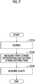
Fig. 7 is a flowchart of an evaluating method according to the embodiment. -
Fig. 8 is a diagram showing an example of a measurement unit according to the embodiment. -
Fig. 9 is a diagram showing another example of the measurement unit according to the embodiment. - Hereinafter, an evaluation system according to an embodiment of the present invention will be described with reference to
Figs. 1 to 9 . - An
evaluation system 1 is a system for evaluating anassembly 50. - As shown in
Fig. 1 , theevaluation system 1 includes ameasurement unit 10, a firstoptical fiber 20, a secondoptical fiber 30, and ashape acquisition unit 40. - The first
optical fiber 20 and the secondoptical fiber 30 are provided in theassembly 50 and receive a strain according to the internal deformation of theassembly 50. - The
measurement unit 10 introduces incident light into each of the firstoptical fiber 20 and the secondoptical fiber 30 and detects outgoing light which is emitted from each of the firstoptical fiber 20 and the secondoptical fiber 30. - The
measurement unit 10 can measure a first strain distribution, which is a distribution of a strain at each position in an axial direction of the firstoptical fiber 20, by detecting the outgoing light from the firstoptical fiber 20. - Similarly, the
measurement unit 10 can measure a second strain distribution, which is a distribution of a strain at each position in the axial direction of the secondoptical fiber 30, by detecting the outgoing light from the secondoptical fiber 30. - The
shape acquisition unit 40 is communicably connected to themeasurement unit 10. Theshape acquisition unit 40 acquires the measured first strain distribution and second strain distribution from themeasurement unit 10. Theshape acquisition unit 40 acquires the shape of a wrinkle WK on asurface 60s of a reinforcedmember 60 from the first strain distribution and the second strain distribution by internal calculation. - The configuration of the
assembly 50 will be described in detail. - The
assembly 50 includes the reinforcedmember 60 and a reinforcingmember 70. - In this embodiment, the reinforced
member 60 is a skin panel. - As shown in
Fig. 2 , the reinforcedmember 60 has afirst composite layer 61, a secondcomposite layer 62, and a thirdcomposite layer 63 in order in a Z direction from thesurface 60s side. Each of thefirst composite layer 61, the secondcomposite layer 62, and the thirdcomposite layer 63 is a prepreg in which a thermosetting resin is impregnated into carbon fibers, and is sequentially laminated. - Further, in this embodiment, the reinforcing
member 70 is a stringer. - Returning to
Fig. 1 , the reinforcingmember 70 extends in one direction. Specifically, the reinforcingmember 70 extends longer in the direction along a Y direction than in the direction along an X direction. - Hereinafter, in the reinforcing
member 70, the direction along the X direction is also referred to as a width direction, and the direction along the Y direction is also referred to as a depth direction. Further, in the reinforcingmember 70 or the reinforcedmember 60, the direction along the Z direction is also referred to as a height direction. - The reinforcing
member 70 is bonded onto thesurface 60s of the reinforcedmember 60. Thesurface 60s of the reinforcedmember 60 and the reinforcingmember 70 are co-bonded by bonding the cured reinforcingmember 70 to thesurface 60s of the reinforcedmember 60 that is a raw material (uncured). - The reinforcing
member 70 hasperipheral edge portions 71 on both sides in the width direction and both sides in the depth direction. Theperipheral edge portions 71 include a pair of widthperipheral edge portions 71x extending in the depth direction on both sides in the width direction of the reinforcingmember 70, and a pair of depthperipheral edge portions 71y extending in the width direction on both sides in the depth direction of the reinforcingmember 70. The widthperipheral edge portion 71x extends longer than the depthperipheral edge portion 71y. - As shown in
Fig. 2 , the firstoptical fiber 20 extends between the firstcomposite layer 61 and the secondcomposite layer 62. - The second
optical fiber 30 extends between the secondcomposite layer 62 and the thirdcomposite layer 63 along the firstoptical fiber 20. - In this embodiment, the first
optical fiber 20 and the secondoptical fiber 30 are provided when the firstcomposite layer 61, the secondcomposite layer 62, and the thirdcomposite layer 63 are laminated. - Therefore, the
surface 60s of the reinforcedmember 60 and the reinforcingmember 70 are co-bonded in a state where the firstoptical fiber 20 is provided between the firstcomposite layer 61 and the secondcomposite layer 62 and the secondoptical fiber 30 is provided between the secondcomposite layer 62 and the thirdcomposite layer 63. - In this embodiment, as shown in
Fig. 2 , as a composite layer, only the secondcomposite layer 62 is formed between the firstoptical fiber 20 and the secondoptical fiber 30. However, as a modification example, in addition to the secondcomposite layer 62, another composite layer may be included between the firstoptical fiber 20 and the secondoptical fiber 30. - Further, in this embodiment, as shown in
Fig. 2 , as a composite layer, only the firstcomposite layer 61 is formed on the firstoptical fiber 20. However, as a modification example, in addition to the firstcomposite layer 61, another composite layer may be included on the firstoptical fiber 20. - Each of the first
optical fiber 20 and the secondoptical fiber 30 intersects at least a part of theperipheral edge portion 71 of the reinforcingmember 70. Specifically, as shown inFig. 1 , each of the firstoptical fiber 20 and the secondoptical fiber 30 meanders over the both sides in the width direction of the reinforcingmember 70 so as to repeatedly intersect the pair of widthperipheral edge portions 71x among theperipheral edge portions 71 of the reinforcingmember 70. - The configuration of the
shape acquisition unit 40 will be described in detail. - As shown in
Fig. 3 , theshape acquisition unit 40 functionally includes a membranestrain calculation unit 41, a bendingstrain calculation unit 42, acurvature calculation unit 43, a rotationangle calculation unit 44, and ashape calculation unit 45. - The membrane
strain calculation unit 41 acquires a membrane strain εa by calculation from a first strain ε1 and a second strain ε2, which are strains at the respective positions in the first strain distribution and the second strain distribution. - The bending
strain calculation unit 42 acquires a bending strain εb by calculation from the first strain ε1 and the second strain ε2, which are strains at the respective positions in the first strain distribution and the second strain distribution. - The
curvature calculation unit 43 acquires a curvature φ of thesurface 60s at each position by calculation. - The rotation
angle calculation unit 44 acquires a rotation angle θ of thesurface 60s at each position by calculation. - The
shape calculation unit 45 acquires the shape of the wrinkle WK by accumulating the rotation angle θ of thesurface 60s at each position. - Each calculation for acquiring the shape of the wrinkle WK in the
shape acquisition unit 40 will be described in detail with reference toFigs. 4 to 6 . - The
shape acquisition unit 40 acquires the shape of the wrinkle WK on thesurface 60s of the reinforcedmember 60 from the first strain distribution and the second strain distribution. - As shown in
Fig. 4 , if the wrinkle WK occurs, the first strain ε1 and the second strain ε2 respectively generate in the firstoptical fiber 20 and the secondoptical fiber 30. - At this time, for example, in the portion shown in
Fig. 5 , the relationship of the second strain ε2>the first strain ε1 is established. In this case, the membrane strain (axial direction strain) εa of the secondcomposite layer 62 can be calculated from εa=(ε2+ε1)/2, and the bending strain εb can be calculated from εb=(ε2-ε1)/2. - By these calculations, the membrane
strain calculation unit 41 and the bendingstrain calculation unit 42 respectively acquire the membrane strain εa and the bending strain εb. - When the position resolution in the X direction that can be measured by the
measurement unit 10 is set to be Δx and the distance between the firstoptical fiber 20 and the secondoptical fiber 30 is set to be d, the curvature φ of thesurface 60s at the location in a measurement range Δx can be calculated from εb/(d/2)=φ. Further, the rotation angle θ of thesurface 60s at the location in the measurement range Δx can be calculated from φ×Δx=θ. - By these calculations, the
curvature calculation unit 43 and the rotationangle calculation unit 44 respectively acquire the curvature φ and the rotation angle θ. - In a case where only εa is calculated in the entire measurement range Δx and εb is almost zero, the measurement range Δx can be regarded as a region where bending deformation does not occur.
- In contrast, the point at which εb starts to increase can be evaluated as the end of the range in which the wrinkle WK occurs. Further, the inclination of each measurement range Δx is obtained by calculating the rotation angle θ in the continuous measurement range Δx, and therefore, by calculating the cumulative value of the inclination in each measurement range Δx, the
shape calculation unit 45 acquires the shape in the height direction of the wrinkle WK. - For example, as shown in
Fig. 6 , by accumulating the rotation angles θ1, θ2, θ3, ..., in each of the measurement ranges Δx1, Δx2, Δx3, ..., theshape calculation unit 45 can acquires the shape of the wrinkle WK. - An evaluating method by the
evaluation system 1 of this embodiment will be described with reference toFig. 7 . - In this evaluating method, the shape of the wrinkle WK which is generated on the
surface 60s after the curing of the reinforcedmember 60 which is a raw material is evaluated. - First, the cured reinforcing
member 70 is placed on thesurface 60s, and the reinforcedmember 60 which is a raw material (uncured) provided with the firstoptical fiber 20 and the secondoptical fiber 30 is cured (ST10: curing step). In this way, the cured reinforcingmember 70 is co-bonded to thesurface 60s. At this time, as shown inFig. 2 , there is a case where the wrinkles WK are generated on thesurface 60s. - Subsequently, the first strain distribution which is a distribution of a strain at each position in the axial direction of the first
optical fiber 20 is measured, and the second strain distribution which is a distribution of a strain at each position in the axial direction of the secondoptical fiber 30 is measured (ST20: measuring step). - Subsequently, the shape of the wrinkle WK on the
surface 60s of the reinforcedmember 60 is acquired from the first strain distribution and the second strain distribution (ST30: step of acquiring the shape). - In this embodiment, as optical fibers, the first
optical fiber 20 and the secondoptical fiber 30 are embedded between the respective layers of the firstcomposite layer 61, the secondcomposite layer 62, and the thirdcomposite layer 63 where the wrinkle WK is generated, and the strain after curing is measured. - By embedding the first
optical fiber 20 and the secondoptical fiber 30 between the respective layers, the amount of deformation can be grasped, and the shape of the wrinkle WK can be evaluated. - By grasping the relative relationship between the strain value and the magnitude of the wrinkle WK in advance, there is also a case where it is possible to evaluate the shape of the wrinkle WK from a strain in one layer. However, the degree of accuracy is not very good.
- In contrast, in the embodiment, since the shape of the wrinkle WK is evaluated from each strain between the two layers, the shape of the wrinkle WK can be acquired with a higher degree of accuracy.
- Further, in this embodiment, each of the first
optical fiber 20 and the secondoptical fiber 30 meanders over both sides in the width direction of the reinforcingmember 70. In this way, the firstoptical fiber 20 and the secondoptical fiber 30 are distributed over the entire region where the reinforcingmember 70 is bonded. - If it is not possible to grasp where and how large wrinkle WK has occurred, it is necessary to use an excessively safe allowable value and design value from visual inspection data of a picked-up location.
- In contrast, in this embodiment, the first
optical fiber 20 and the secondoptical fiber 30 are distributed over the entire region where the reinforcingmember 70 is bonded, whereby it is possible to perform the entire surface inspection, and it is possible to grasp where and how large wrinkle WK has occurred. In this way, it is possible to specify a location where the wrinkle WK has not occurred. - Therefore, the strength design value of the location where the wrinkle WK has not occurred can be utilized to the maximum.
- In this embodiment, the
measurement unit 10 measures the strain distribution at each position in the axial direction of the firstoptical fiber 20 and the secondoptical fiber 30 by introducing incident light into the firstoptical fiber 20 and the secondoptical fiber 30 and detecting outgoing light from the firstoptical fiber 20 and the secondoptical fiber 30. However, the strain distribution may be measured in any manner. - For example, the
measurement unit 10 as shown inFig. 8 may be used as themeasurement unit 10 that measures the strain distribution at each position in the axial direction of the firstoptical fiber 20 and the secondoptical fiber 30. - The
measurement unit 10 shown inFig. 8 is a measurement unit that uses BOCDA (Brillouin optical correlation region analysis method, refer to Japanese Patent No.4652309 - In the
measurement unit 10 using BOCDA, another light (probe light) whose frequency is shifted is introduced from the other end of each of the firstoptical fiber 20 and the secondoptical fiber 30 to weak backscattered light which is generated by introducing incident light (pump light) from one end of each of the firstoptical fiber 20 and the secondoptical fiber 30. Then, themeasurement unit 10 detects stimulated Brillouin scattered light SBS (Stimulated Brillouin Scattering) as detection light by the interaction between the pump light and the probe light. Due to the shift of the optical spectrum of the SBS, themeasurement unit 10 can detect the strain which is provided to the firstoptical fiber 20 at each position in the axial direction. Similarly, due to the shift of the optical spectrum of the SBS, themeasurement unit 10 can detect the strain which is provided to the secondoptical fiber 30 at each position in the axial direction. - In the case of the
measurement unit 10 shown inFig. 8 , by modulating the frequency and intensity of each incident light, it is possible to specify the location of the SBS to be measured, and themeasurement unit 10 can measure the first strain distribution which is a strain at each position in the axial direction of the first optical fiber. - Similarly, by modulating the frequency and strength of each incident light, the
measurement unit 10 can measure the second strain distribution which is a strain at each position in the axial direction of the secondoptical fiber 30. - Further, instead of the
measurement unit 10 that measures the strain distribution at each position in the axial direction of the optical fiber, the firstoptical fiber 20, and the secondoptical fiber 30, a measurement unit 10', a first optical fiber 20', and a second optical fiber 30', as shown inFig.9 , may be used. - The measurement unit 10' shown in
Fig. 9 is a measurement unit that uses FBG (Fiber Bragg Grating). - In the measurement unit 10' using the FBG, incident light is introduced from one end of the first optical fiber 20' in which a diffraction grating (Bragg Grating) 80 that reflects light having a different specific wavelength is provided at each position in the axial direction. The incident light is separated into back reflected light and transmitted light by the
diffraction grating 80. The measurement unit 10' can measure the first strain distribution which is a strain at eachdiffraction grating 80, that is, a strain at each position, by detecting the back reflected light or the transmitted light as a detection light and measuring the optical spectrum or the peak frequency fluctuation of the back reflected light or the transmitted light. - Similarly, in the measurement unit 10' using the FBG, incident light is introduced from one end of the second optical fiber 30' in which the
diffraction grating 80 that reflects light having a different specific wavelength is provided at each position in the axial direction. The measurement unit 10' can measure the second strain distribution which is a strain at eachdiffraction grating 80, that is, a strain at each position, by detecting the back reflected light or the transmitted light as a detection light and measuring the optical spectrum or the peak frequency fluctuation of the back reflected light or the transmitted light. - In the above embodiment, the first optical fiber is provided between the first composite layer and the second composite layer, and the second optical fiber is provided between the second composite layer and the third composite layer.
- As a modification example, a configuration may be adopted in which with respect to a reinforced member having a first composite layer, a second composite layer, a third composite layer, and a fourth composite layer in order, a third strain distribution is measured by further providing a third optical fiber between the third composite layer and the fourth composite layer and the shape of the wrinkle on the surface of the reinforced member is acquired from the first strain distribution, the second strain distribution, and the third strain distribution.
- As another modification example, a configuration may be adopted in which the number of fibers is further increased and the shape of the wrinkle on the surface of the reinforced member is acquired from more strain distributions.
- In the above embodiment, each of the first optical fiber and the second optical fiber intersects the width
peripheral edge portion 71x. As a modification example, the first optical fiber and the second optical fiber may further intersect the depthperipheral edge portion 71y, in addition to the widthperipheral edge portion 71x. If the first optical fiber and the second optical fiber intersect the depthperipheral edge portion 71y, the shape of the wrinkle WK which is generated around the depthperipheral edge portion 71y can also be acquired. - In the above embodiment, in the
shape acquisition unit 40, the shape of the wrinkle WK on thesurface 60s of the reinforcedmember 60 is acquired by performing calculation on the first strain distribution and the second strain distribution by various calculation units. However, the shape of the wrinkle WK on thesurface 60s may be acquired without performing calculation in the various calculation units. - As a modification example, the
shape acquisition unit 40 may store the shape of the wrinkle WK with respect to each of various first and second strain distributions in advance. In this case, theshape acquisition unit 40 reads the shape of the wrinkle WK on thesurface 60s with respect to the measured first and second strain distributions from among the stored shapes of the plurality of wrinkles WK, and acquires the shape of the wrinkle WK on thesurface 60s. - In each of the embodiments described above, a program for realizing various functions of the shape acquisition unit may be recorded on a computer-readable recording medium, and the program recorded on the recording medium may be read into a computer system and executed by the computer system, thereby performing various processes. Here, the processes of various processes at a CPU of the computer system are stored in the computer-readable recording medium in the form of a program, and a computer reads and executes this program, whereby the various processes are performed. Further, the computer-readable recording medium refers to a magnetic disk, a magneto-optical disk, a CD-ROM, a DVD-ROM, a semiconductor memory, or the like. Further, the computer program may be distributed to a computer through a communication line, and the computer that has received the distribution may execute the program.
- Some embodiments of the present invention have been described above. However, these embodiments have been presented as examples and are not intended to limit the scope of the invention. These embodiments can be implemented in other various forms, and various omissions, replacements, and changes can be made within a scope which does not depart from the gist of the invention. These embodiments or modifications thereof are included in the scope or gist of the invention and are also included in the inventions described in the claims and equivalents thereof.
- According to the aspects described above, it is possible to evaluate a wrinkle.
-
- 1:
- evaluation system
- 10:
- measurement unit
- 10':
- measurement unit
- 20:
- first optical fiber
- 20':
- first optical fiber
- 30:
- second optical fiber
- 30':
- second optical fiber
- 40:
- shape acquisition unit
- 41:
- membrane strain calculation unit
- 42:
- bending strain calculation unit
- 43:
- curvature calculation unit
- 44:
- rotation angle calculation unit
- 45:
- shape calculation unit
- 50:
- assembly
- 60:
- reinforced member
- 60s:
- surface
- 61:
- first composite layer
- 62:
- second composite layer
- 63:
- third composite layer
- 70:
- reinforcing member
- 71:
- peripheral edge portion
- 71x:
- width peripheral edge portion
- 71y:
- depth peripheral edge portion
- 80:
- diffraction grating
- WK:
- wrinkle
- Δx:
- measurement range
- θ:
- rotation angle
Claims (5)
- An evaluating method for evaluating an assembly provided with a reinforced member having a first composite layer, a second composite layer, and a third composite layer in order, and a reinforcing member fixed to a surface of the reinforced member, the method comprising:a step of measuring a first strain distribution that is a distribution of a strain at each position in an axial direction of a first optical fiber extending between the first composite layer and the second composite layer by introducing incident light into the first optical fiber and detecting outgoing light from the first optical fiber, and measuring a second strain distribution that is a distribution of a strain at each position in an axial direction of a second optical fiber extending between the second composite layer and the third composite layer along the first optical fiber by introducing incident light into the second optical fiber and detecting outgoing light from the second optical fiber; anda step of acquiring a shape of a wrinkle on the surface of the reinforced member from the first strain distribution and the second strain distribution.
- The evaluating method according to claim 1, wherein the reinforcing member has a peripheral edge portion, and
each of the first optical fiber and the second optical fiber intersects at least a part of the peripheral edge portion. - The evaluating method according to claim 2, wherein the reinforcing member is a stringer extending in one direction, and
the first optical fiber and the second optical fiber intersect at least a part of an edge portion extending in the one direction in the peripheral edge portion. - The evaluating method according to any one of claims 1 to 3, wherein the first optical fiber and the second optical fiber meander over both sides of the reinforcing member.
- An evaluation system that evaluates an assembly provided with a reinforced member having a first composite layer, a second composite layer, and a third composite layer in order, and a reinforcing member fixed to a surface of the reinforced member, the system comprising:a measurement unit that measures a first strain distribution that is a distribution of a strain at each position in an axial direction of a first optical fiber extending between the first composite layer and the second composite layer by introducing incident light into the first optical fiber and detecting outgoing light from the first optical fiber, and measures a second strain distribution that is a distribution of a strain at each position in an axial direction of a second optical fiber extending between the second composite layer and the third composite layer along the first optical fiber by introducing incident light into the second optical fiber and detecting outgoing light from the second optical fiber; anda shape acquisition unit that acquires a shape of a wrinkle on the surface of the reinforced member from the first strain distribution and the second strain distribution.
Applications Claiming Priority (2)
| Application Number | Priority Date | Filing Date | Title |
|---|---|---|---|
| JP2018042013A JP6873073B2 (en) | 2018-03-08 | 2018-03-08 | Evaluation method and evaluation system |
| PCT/JP2019/008355 WO2019172178A1 (en) | 2018-03-08 | 2019-03-04 | Evaluating method and evaluation system |
Publications (1)
| Publication Number | Publication Date |
|---|---|
| EP3764055A1 true EP3764055A1 (en) | 2021-01-13 |
Family
ID=67847320
Family Applications (1)
| Application Number | Title | Priority Date | Filing Date |
|---|---|---|---|
| EP19764787.8A Withdrawn EP3764055A1 (en) | 2018-03-08 | 2019-03-04 | Evaluating method and evaluation system |
Country Status (4)
| Country | Link |
|---|---|
| US (1) | US11181360B2 (en) |
| EP (1) | EP3764055A1 (en) |
| JP (1) | JP6873073B2 (en) |
| WO (1) | WO2019172178A1 (en) |
Families Citing this family (3)
| Publication number | Priority date | Publication date | Assignee | Title |
|---|---|---|---|---|
| KR102378731B1 (en) * | 2020-10-22 | 2022-03-28 | 한국건설기술연구원 | Drop confirming system for adhesional reinforcement under structure using 3-wire optical fiber, and method for the same |
| CN112284304A (en) * | 2020-10-27 | 2021-01-29 | 常州市新创智能科技有限公司 | Method for adjusting straightness of pultruded plate |
| CN112800642B (en) * | 2020-12-29 | 2022-07-19 | 中国人民解放军国防科技大学 | Film wrinkle strength evaluation method and system based on nonlinear finite element |
Family Cites Families (20)
| Publication number | Priority date | Publication date | Assignee | Title |
|---|---|---|---|---|
| US4936649A (en) * | 1989-01-25 | 1990-06-26 | Lymer John D | Damage evaluation system and method using optical fibers |
| DE3926457A1 (en) * | 1989-08-10 | 1991-04-25 | Buchholz Juergen | Fibre=optic sensor for parameter measurement or transmission |
| JPH04361126A (en) * | 1991-06-07 | 1992-12-14 | Ishikawajima Harima Heavy Ind Co Ltd | Method for measuring internal distortion of fiber-reinforced compound material lamination plate |
| US5649035A (en) * | 1995-11-03 | 1997-07-15 | Simula Inc. | Fiber optic strain gauge patch |
| JP3829180B2 (en) * | 2002-02-08 | 2006-10-04 | 飛島建設株式会社 | Ground deformation measurement system using optical fiber sensor |
| JP3848660B2 (en) * | 2004-05-06 | 2006-11-22 | 川崎重工業株式会社 | Damage detection device |
| JP4652309B2 (en) | 2006-10-31 | 2011-03-16 | 三菱重工業株式会社 | Optical fiber characteristic measuring device |
| EP2672234B1 (en) * | 2012-06-05 | 2014-12-03 | Airbus Operations GmbH | System and method for monitoring a component in production as well as in service |
| JP6157186B2 (en) * | 2013-04-05 | 2017-07-05 | 三菱電機株式会社 | Manufacturing method of fiber reinforced composite material structure |
| CA2909484C (en) | 2013-05-14 | 2019-08-20 | Mitsubishi Heavy Industries, Ltd. | Bonded structure and bonding-condition detecting method |
| KR101465156B1 (en) * | 2013-10-01 | 2014-11-26 | 한국표준과학연구원 | FBG sensor for measuring the maximum strain, manufacturing method thereof and operating method thereof |
| EP3211399B1 (en) * | 2015-01-15 | 2019-03-27 | Mitsubishi Heavy Industries, Ltd. | Bonded structure, method for manufacturing same, and bonding state detection method |
| JP6346214B2 (en) * | 2016-03-24 | 2018-06-20 | 株式会社Subaru | Composite material forming jig, composite material forming method, ultrasonic inspection system, ultrasonic inspection method, and aircraft structure |
| CN106092160A (en) * | 2016-07-15 | 2016-11-09 | 东南大学 | A kind of manufacture method of the multi-functional FRP intelligent anchor rod of multiple spot temperature compensation |
| JP2018042013A (en) | 2016-09-05 | 2018-03-15 | シャープ株式会社 | Guard terminal device, access point, radio communication device, and transmission method |
| EP3292993A1 (en) * | 2016-09-08 | 2018-03-14 | Airbus Operations GmbH | Damage visualization |
| CN106931896B (en) * | 2017-03-31 | 2020-04-17 | 四川大学 | Optical fiber sensing technology and system for deformation monitoring of geomembrane anti-seepage earth-rock dam |
| CN109696140A (en) * | 2017-10-23 | 2019-04-30 | 崴强科技股份有限公司 | Paper warpage detection device and its detection method |
| JP7131967B2 (en) * | 2018-05-30 | 2022-09-06 | 株式会社Subaru | Optical inspection system, optical inspection method, and aircraft structure |
| US11590676B2 (en) * | 2018-08-21 | 2023-02-28 | United States Of America As Represented By The Administrator Of Nasa | Guided wave-based system for cure monitoring of composites using piezoelectric discs and fiber Bragg gratings/phase-shifted Bragg gratings |
-
2018
- 2018-03-08 JP JP2018042013A patent/JP6873073B2/en active Active
-
2019
- 2019-03-04 EP EP19764787.8A patent/EP3764055A1/en not_active Withdrawn
- 2019-03-04 US US16/765,603 patent/US11181360B2/en active Active
- 2019-03-04 WO PCT/JP2019/008355 patent/WO2019172178A1/en active Application Filing
Also Published As
| Publication number | Publication date |
|---|---|
| JP6873073B2 (en) | 2021-05-19 |
| WO2019172178A1 (en) | 2019-09-12 |
| JP2019158403A (en) | 2019-09-19 |
| US20200309512A1 (en) | 2020-10-01 |
| US11181360B2 (en) | 2021-11-23 |
Similar Documents
| Publication | Publication Date | Title |
|---|---|---|
| EP3764055A1 (en) | Evaluating method and evaluation system | |
| Grave et al. | Measuring changing strain fields in composites with Distributed Fiber-Optic Sensing using the optical backscatter reflectometer | |
| EP1672351B1 (en) | Manufacturing method for manufacturing a modular sensor for damage detection | |
| US7283693B2 (en) | Method to monitor structural damage occurrence and progression in monolithic composite structures using fibre Bragg grating sensors | |
| EP2672234B1 (en) | System and method for monitoring a component in production as well as in service | |
| US4936649A (en) | Damage evaluation system and method using optical fibers | |
| Khan et al. | Investigation on interlaminar delamination tendency of multidirectional carbon fiber composites | |
| US8260093B2 (en) | Component monitoring arrangement | |
| Güemes et al. | Damage detection in composite structures from fibre optic distributed strain measurements | |
| Ciminello | Distributed fiber optic for structural health monitoring system based on auto-correlation of the first-order derivative of strain | |
| Sala et al. | Fibre optics health monitoring for aeronautical applications | |
| Rao et al. | Structural health monitoring (SHM) using strain gauges, PVDF film and fiber bragg grating (FBG) sensors: A comparative study | |
| EP2187165B1 (en) | Method for detecting crack occurrence position | |
| Ogisu et al. | Feasibility studies on active damage detection for CFRP aircraft bonding structures | |
| CA3134851C (en) | Strength evaluation device and strength evaluation method | |
| Ding et al. | Damage detection in holed carbon fiber composite laminates using embedded fiber Bragg grating sensors based on strain information | |
| GB2558899A (en) | Sensor | |
| Airoldi et al. | Design of health and usage monitoring systems based on optical fibers for composite wing spars | |
| Ciminello et al. | Circular patch sensor based on distributed fiber optic technology for tensile and bending loads identification | |
| Li et al. | A novel damage detection method for carbon fibre reinforced polymer structures based on distributed strain measurements with fibre optical sensor | |
| Ameduri et al. | Ring patch sensor based on FBG array for normal and bending load recognition | |
| Todoroki | Self-sensing composites and optimization of composite structures in Japan | |
| Guemes et al. | Embedded fiber Bragg grating as local damage sensors for composite materials | |
| WO2024075077A1 (en) | Method for monitoring structural elements in composite | |
| Prusty et al. | Failure investigation of top-hat composite stiffened panels |
Legal Events
| Date | Code | Title | Description |
|---|---|---|---|
| PUAI | Public reference made under article 153(3) epc to a published international application that has entered the european phase |
Free format text: ORIGINAL CODE: 0009012 |
|
| STAA | Information on the status of an ep patent application or granted ep patent |
Free format text: STATUS: THE APPLICATION HAS BEEN WITHDRAWN |
|
| 17P | Request for examination filed |
Effective date: 20200525 |
|
| AK | Designated contracting states |
Kind code of ref document: A1 Designated state(s): AL AT BE BG CH CY CZ DE DK EE ES FI FR GB GR HR HU IE IS IT LI LT LU LV MC MK MT NL NO PL PT RO RS SE SI SK SM TR |
|
| AX | Request for extension of the european patent |
Extension state: BA ME |
|
| 18W | Application withdrawn |
Effective date: 20201223 |
|
| RIN1 | Information on inventor provided before grant (corrected) |
Inventor name: MORISHITA, KUNIHIRO Inventor name: SAITO, NOZOMI |