EP3762087B1 - Burr hole plugs for electrical stimulation systems - Google Patents
Burr hole plugs for electrical stimulation systems Download PDFInfo
- Publication number
- EP3762087B1 EP3762087B1 EP19712360.7A EP19712360A EP3762087B1 EP 3762087 B1 EP3762087 B1 EP 3762087B1 EP 19712360 A EP19712360 A EP 19712360A EP 3762087 B1 EP3762087 B1 EP 3762087B1
- Authority
- EP
- European Patent Office
- Prior art keywords
- lead
- base
- burr hole
- retention members
- hole plug
- Prior art date
- Legal status (The legal status is an assumption and is not a legal conclusion. Google has not performed a legal analysis and makes no representation as to the accuracy of the status listed.)
- Active
Links
- 230000000638 stimulation Effects 0.000 title claims description 75
- 230000014759 maintenance of location Effects 0.000 claims description 55
- 210000003625 skull Anatomy 0.000 claims description 21
- 238000003780 insertion Methods 0.000 claims description 7
- 230000037431 insertion Effects 0.000 claims description 7
- 229920001296 polysiloxane Polymers 0.000 claims description 3
- 230000006835 compression Effects 0.000 claims description 2
- 238000007906 compression Methods 0.000 claims description 2
- 210000004556 brain Anatomy 0.000 description 19
- 210000001519 tissue Anatomy 0.000 description 13
- 239000000463 material Substances 0.000 description 8
- 230000006854 communication Effects 0.000 description 5
- 238000004891 communication Methods 0.000 description 5
- 229910052751 metal Inorganic materials 0.000 description 5
- 239000002184 metal Substances 0.000 description 5
- 210000000278 spinal cord Anatomy 0.000 description 5
- 230000007383 nerve stimulation Effects 0.000 description 4
- 210000000578 peripheral nerve Anatomy 0.000 description 4
- 229920003023 plastic Polymers 0.000 description 4
- 239000004033 plastic Substances 0.000 description 4
- -1 polyethylene Polymers 0.000 description 4
- 239000000919 ceramic Substances 0.000 description 3
- 230000008878 coupling Effects 0.000 description 3
- 238000010168 coupling process Methods 0.000 description 3
- 238000005859 coupling reaction Methods 0.000 description 3
- 238000000034 method Methods 0.000 description 3
- 210000005036 nerve Anatomy 0.000 description 3
- 210000002569 neuron Anatomy 0.000 description 3
- KDLHZDBZIXYQEI-UHFFFAOYSA-N Palladium Chemical compound [Pd] KDLHZDBZIXYQEI-UHFFFAOYSA-N 0.000 description 2
- 206010040840 Skin erosion Diseases 0.000 description 2
- 210000004027 cell Anatomy 0.000 description 2
- 239000004020 conductor Substances 0.000 description 2
- 208000037265 diseases, disorders, signs and symptoms Diseases 0.000 description 2
- 230000003628 erosive effect Effects 0.000 description 2
- 238000002513 implantation Methods 0.000 description 2
- 210000003205 muscle Anatomy 0.000 description 2
- BASFCYQUMIYNBI-UHFFFAOYSA-N platinum Chemical compound [Pt] BASFCYQUMIYNBI-UHFFFAOYSA-N 0.000 description 2
- 210000003594 spinal ganglia Anatomy 0.000 description 2
- 230000001225 therapeutic effect Effects 0.000 description 2
- 238000011282 treatment Methods 0.000 description 2
- 208000036829 Device dislocation Diseases 0.000 description 1
- 206010021639 Incontinence Diseases 0.000 description 1
- 206010033799 Paralysis Diseases 0.000 description 1
- 229910000566 Platinum-iridium alloy Inorganic materials 0.000 description 1
- 239000004698 Polyethylene Substances 0.000 description 1
- 229920002396 Polyurea Polymers 0.000 description 1
- RTAQQCXQSZGOHL-UHFFFAOYSA-N Titanium Chemical compound [Ti] RTAQQCXQSZGOHL-UHFFFAOYSA-N 0.000 description 1
- 210000000683 abdominal cavity Anatomy 0.000 description 1
- 229910045601 alloy Inorganic materials 0.000 description 1
- 239000000956 alloy Substances 0.000 description 1
- 238000005452 bending Methods 0.000 description 1
- 230000007175 bidirectional communication Effects 0.000 description 1
- 239000000560 biocompatible material Substances 0.000 description 1
- 230000005540 biological transmission Effects 0.000 description 1
- 210000005013 brain tissue Anatomy 0.000 description 1
- 239000003990 capacitor Substances 0.000 description 1
- 239000000969 carrier Substances 0.000 description 1
- 230000001413 cellular effect Effects 0.000 description 1
- 208000022371 chronic pain syndrome Diseases 0.000 description 1
- 210000003109 clavicle Anatomy 0.000 description 1
- 230000001112 coagulating effect Effects 0.000 description 1
- 201000010099 disease Diseases 0.000 description 1
- 208000037765 diseases and disorders Diseases 0.000 description 1
- 208000035475 disorder Diseases 0.000 description 1
- 238000005553 drilling Methods 0.000 description 1
- 210000001951 dura mater Anatomy 0.000 description 1
- 239000000446 fuel Substances 0.000 description 1
- 210000005003 heart tissue Anatomy 0.000 description 1
- 230000001939 inductive effect Effects 0.000 description 1
- 208000015181 infectious disease Diseases 0.000 description 1
- 238000011835 investigation Methods 0.000 description 1
- 229910052741 iridium Inorganic materials 0.000 description 1
- GKOZUEZYRPOHIO-UHFFFAOYSA-N iridium atom Chemical compound [Ir] GKOZUEZYRPOHIO-UHFFFAOYSA-N 0.000 description 1
- 230000003902 lesion Effects 0.000 description 1
- 230000007246 mechanism Effects 0.000 description 1
- 230000004048 modification Effects 0.000 description 1
- 238000012986 modification Methods 0.000 description 1
- 210000001087 myotubule Anatomy 0.000 description 1
- 210000004126 nerve fiber Anatomy 0.000 description 1
- 230000001537 neural effect Effects 0.000 description 1
- 210000000056 organ Anatomy 0.000 description 1
- 230000003204 osmotic effect Effects 0.000 description 1
- 229910052763 palladium Inorganic materials 0.000 description 1
- XSKIUFGOTYHDLC-UHFFFAOYSA-N palladium rhodium Chemical compound [Rh].[Pd] XSKIUFGOTYHDLC-UHFFFAOYSA-N 0.000 description 1
- 230000000737 periodic effect Effects 0.000 description 1
- 229910052697 platinum Inorganic materials 0.000 description 1
- HWLDNSXPUQTBOD-UHFFFAOYSA-N platinum-iridium alloy Chemical class [Ir].[Pt] HWLDNSXPUQTBOD-UHFFFAOYSA-N 0.000 description 1
- 229920000573 polyethylene Polymers 0.000 description 1
- 229920002635 polyurethane Polymers 0.000 description 1
- 239000004814 polyurethane Substances 0.000 description 1
- 229920003226 polyurethane urea Polymers 0.000 description 1
- 230000004043 responsiveness Effects 0.000 description 1
- 238000000926 separation method Methods 0.000 description 1
- 206010040872 skin infection Diseases 0.000 description 1
- 239000007779 soft material Substances 0.000 description 1
- 208000020431 spinal cord injury Diseases 0.000 description 1
- 238000001356 surgical procedure Methods 0.000 description 1
- 230000008685 targeting Effects 0.000 description 1
- 230000002123 temporal effect Effects 0.000 description 1
- 238000012360 testing method Methods 0.000 description 1
- 238000002560 therapeutic procedure Methods 0.000 description 1
- 229920001169 thermoplastic Polymers 0.000 description 1
- 239000004416 thermosoftening plastic Substances 0.000 description 1
- 229910052719 titanium Inorganic materials 0.000 description 1
- 239000010936 titanium Substances 0.000 description 1
- WFKWXMTUELFFGS-UHFFFAOYSA-N tungsten Chemical compound [W] WFKWXMTUELFFGS-UHFFFAOYSA-N 0.000 description 1
- 229910052721 tungsten Inorganic materials 0.000 description 1
- 239000010937 tungsten Substances 0.000 description 1
Images


Classifications
-
- A—HUMAN NECESSITIES
- A61—MEDICAL OR VETERINARY SCIENCE; HYGIENE
- A61N—ELECTROTHERAPY; MAGNETOTHERAPY; RADIATION THERAPY; ULTRASOUND THERAPY
- A61N1/00—Electrotherapy; Circuits therefor
- A61N1/02—Details
- A61N1/04—Electrodes
- A61N1/05—Electrodes for implantation or insertion into the body, e.g. heart electrode
- A61N1/0526—Head electrodes
- A61N1/0529—Electrodes for brain stimulation
- A61N1/0539—Anchoring of brain electrode systems, e.g. within burr hole
-
- A—HUMAN NECESSITIES
- A61—MEDICAL OR VETERINARY SCIENCE; HYGIENE
- A61B—DIAGNOSIS; SURGERY; IDENTIFICATION
- A61B90/00—Instruments, implements or accessories specially adapted for surgery or diagnosis and not covered by any of the groups A61B1/00 - A61B50/00, e.g. for luxation treatment or for protecting wound edges
- A61B90/10—Instruments, implements or accessories specially adapted for surgery or diagnosis and not covered by any of the groups A61B1/00 - A61B50/00, e.g. for luxation treatment or for protecting wound edges for stereotaxic surgery, e.g. frame-based stereotaxis
-
- A—HUMAN NECESSITIES
- A61—MEDICAL OR VETERINARY SCIENCE; HYGIENE
- A61N—ELECTROTHERAPY; MAGNETOTHERAPY; RADIATION THERAPY; ULTRASOUND THERAPY
- A61N1/00—Electrotherapy; Circuits therefor
- A61N1/18—Applying electric currents by contact electrodes
- A61N1/32—Applying electric currents by contact electrodes alternating or intermittent currents
- A61N1/36—Applying electric currents by contact electrodes alternating or intermittent currents for stimulation
- A61N1/3605—Implantable neurostimulators for stimulating central or peripheral nerve system
-
- A—HUMAN NECESSITIES
- A61—MEDICAL OR VETERINARY SCIENCE; HYGIENE
- A61N—ELECTROTHERAPY; MAGNETOTHERAPY; RADIATION THERAPY; ULTRASOUND THERAPY
- A61N1/00—Electrotherapy; Circuits therefor
- A61N1/18—Applying electric currents by contact electrodes
- A61N1/32—Applying electric currents by contact electrodes alternating or intermittent currents
- A61N1/36—Applying electric currents by contact electrodes alternating or intermittent currents for stimulation
- A61N1/372—Arrangements in connection with the implantation of stimulators
-
- A—HUMAN NECESSITIES
- A61—MEDICAL OR VETERINARY SCIENCE; HYGIENE
- A61B—DIAGNOSIS; SURGERY; IDENTIFICATION
- A61B90/00—Instruments, implements or accessories specially adapted for surgery or diagnosis and not covered by any of the groups A61B1/00 - A61B50/00, e.g. for luxation treatment or for protecting wound edges
- A61B90/10—Instruments, implements or accessories specially adapted for surgery or diagnosis and not covered by any of the groups A61B1/00 - A61B50/00, e.g. for luxation treatment or for protecting wound edges for stereotaxic surgery, e.g. frame-based stereotaxis
- A61B2090/103—Cranial plugs for access to brain
-
- A—HUMAN NECESSITIES
- A61—MEDICAL OR VETERINARY SCIENCE; HYGIENE
- A61N—ELECTROTHERAPY; MAGNETOTHERAPY; RADIATION THERAPY; ULTRASOUND THERAPY
- A61N1/00—Electrotherapy; Circuits therefor
- A61N1/02—Details
- A61N1/04—Electrodes
- A61N1/05—Electrodes for implantation or insertion into the body, e.g. heart electrode
- A61N1/0526—Head electrodes
- A61N1/0529—Electrodes for brain stimulation
- A61N1/0534—Electrodes for deep brain stimulation
Definitions
- the present disclosure is also directed to burr hole plugs and implantable electrical stimulation systems including the burr hole plugs.
- Implantable electrical stimulation systems have proven therapeutic in a variety of diseases and disorders.
- stimulation of the brain such as deep brain stimulation
- spinal cord stimulation systems have been used as a therapeutic modality for the treatment of chronic pain syndromes.
- Peripheral nerve stimulation has been used to treat incontinence, as well as a number of other applications under investigation.
- Functional electrical stimulation systems have been applied to restore some functionality to paralyzed extremities in spinal cord injury patients.
- a stimulator can include a control module (with a pulse generator), one or more leads, and an array of stimulator electrodes on each lead.
- the stimulator electrodes are in contact with or near the brain, nerves, or other tissue to be stimulated.
- the pulse generator in the control module generates electrical pulses that are delivered by the electrodes to body tissue.
- US 2004/0034367 A1 discloses a cranial burr hole plug with an insertion tool and method of implantation.
- the burr hole plug includes a shell, a collet interlocked within the shell, a clamp compressing the collet around an elongated medical device exiting the skull of a patient, such as a catheter or lead, and a cover over the clamp, collet, and shell.
- US 2014/0243945 A1 discloses a burr hole plug that comprises a plug base configured for being mounted around a burr hole, and having an aperture through which an elongated medical device exiting the burr hole may pass.
- the burr hole plug further comprises a retainer configured for being mounted within the plug base aperture.
- the retainer includes a retainer support, a slot formed in the retainer support for receiving the medical device, and a clamping mechanism having a clamping bar and a flange slidably engaged with the retainer support to laterally slide the clamping bar to secure the medical device.
- the invention is defined by the burr hole plug of claim 1 and the system for electrical stimulation comprising such a burr hole plug of claim 14. Further aspects and preferred embodiments are defined in the appended claims. Aspects, embodiments and examples of the present disclosure which do not fall under the scope of the appended claims do not form part of the invention and are merely provided for illustrative purposes. Furthermore, the methods presented in the present description are provided for illustrative purposes only and do not form part of the present invention.
- the present disclosure is directed to the area of implantable electrical stimulation systems.
- the present disclosure is also directed to burr hole plugs and implantable electrical stimulation systems including the burr hole plugs.
- Suitable implantable electrical stimulation systems include, but are not limited to, a least one lead with one or more electrodes disposed on a distal portion of the lead and one or more terminals disposed on one or more proximal portions of the lead.
- Leads include, for example, percutaneous leads, paddle leads, cuff leads, or any other arrangement of electrodes on a lead. Examples of electrical stimulation systems with leads are found in, for example, U.S. Patents Nos.
- 2007/0150036 2009/0187222 ; 2009/0276021 ; 2010/0076535 ; 2010/0268298 ; 2011/0005069 ; 2011/0004267 ; 2011/0078900 ; 2011/0130817 ; 2011/0130818 ; 2011/0238129 ; 2011/0313500 ; 2012/0016378 ; 2012/0046710 ; 2012/0071949 ; 2012/0165911 ; 2012/0197375 ; 2012/0203316 ; 2012/0203320 ; 2012/0203321 ; 2012/0316615 ; 2013/0105071 ; and 2013/0197602 .
- a percutaneous lead will be exemplified, but it will be understood that the systems described herein are also applicable to paddle leads and other leads.
- a percutaneous lead for electrical stimulation (for example, deep brain, spinal cord, peripheral nerve, or cardiac-tissue) includes stimulation electrodes that can be ring electrodes, segmented electrodes that extend only partially around the circumference of the lead, or any other type of electrode, or any combination thereof.
- the segmented electrodes can be provided in sets of electrodes, with each set having electrodes circumferentially distributed about the lead at a particular longitudinal position.
- a set of segmented electrodes can include any suitable number of electrodes including, for example, two, three, four, or more electrodes.
- the leads are described herein relative to use for deep brain stimulation, but it will be understood that such leads can be used for applications other than deep brain stimulation, including spinal cord stimulation, peripheral nerve stimulation, dorsal root ganglion stimulation, sacral nerve stimulation, or stimulation of other nerves, muscles, and tissues.
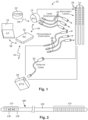
- an electrical stimulation system 10 includes one or more stimulation leads 12 and an implantable pulse generator (IPG) 14.
- the system 10 can also include one or more of an external remote control (RC) 16, a clinician's programmer (CP) 18, an external trial stimulator (ETS) 20, or an external charger 22.
- RC external remote control
- CP clinician's programmer
- ETS external trial stimulator
- the IPG 14 is physically connected, optionally, via one or more lead extensions 24, to the stimulation lead(s) 12. Each lead carries multiple electrodes 26 arranged in an array.
- the IPG 14 includes pulse generation circuitry that delivers electrical stimulation energy in the form of, for example, a pulsed electrical waveform (i.e., a temporal series of electrical pulses) to the electrode array 26 in accordance with a set of stimulation parameters.
- the implantable pulse generator can be implanted into a patient's body, for example, below the patient's clavicle area or within the patient's abdominal cavity.
- the implantable pulse generator can have eight stimulation channels which may be independently programmable to control the magnitude of the current stimulus from each channel.
- the implantable pulse generator can have more or fewer than eight stimulation channels (e.g., 4-, 6-, 16-, 32-, or more stimulation channels).
- the implantable pulse generator can have one, two, three, four, or more connector ports, for receiving the terminals of the leads and/or lead extensions.
- the ETS 20 may also be physically connected, optionally via the percutaneous lead extensions 28 and external cable 30, to the stimulation leads 12.
- One difference between the ETS 20 and the IPG 14 is that the ETS 20 is often a non-implantable device that is used on a trial basis after the neurostimulation leads 12 have been implanted and prior to implantation of the IPG 14, to test the responsiveness of the stimulation that is to be provided. Any functions described herein with respect to the IPG 14 can likewise be performed with respect to the ETS 20.
- the RC 16 may be used to telemetrically communicate with or control the IPG 14 or ETS 20 via a uni- or bi-directional wireless communications link 32. Once the IPG 14 and neurostimulation leads 12 are implanted, the RC 16 may be used to telemetrically communicate with or control the IPG 14 via a uni- or bi-directional communications link 34. Such communication or control allows the IPG 14 to be turned on or off and to be programmed with different stimulation parameter sets. The IPG 14 may also be operated to modify the programmed stimulation parameters to actively control the characteristics of the electrical stimulation energy output by the IPG 14.
- the CP 18 allows a user, such as a clinician, the ability to program stimulation parameters for the IPG 14 and ETS 20 in the operating room and in follow-up sessions. Alternately, or additionally, stimulation parameters can be programed via wireless communications (e.g., Bluetooth) between the RC 16 (or external device such as a hand-held electronic device) and the IPG 14.
- wireless communications e.g., Bluetooth
- the CP 18 may perform this function by indirectly communicating with the IPG 14 or ETS 20, through the RC 16, via a wireless communications link 36. Alternatively, the CP 18 may directly communicate with the IPG 14 or ETS 20 via a wireless communications link (not shown).
- the stimulation parameters provided by the CP 18 are also used to program the RC 16, so that the stimulation parameters can be subsequently modified by operation of the RC 16 in a stand-alone mode (i.e., without the assistance of the CP 18).
- control module is used herein to describe a pulse generator (e.g., the IPG 14 or the ETS 20 of Figure 1 ). Stimulation signals generated by the control module are emitted by electrodes of the lead(s) to stimulate patient tissue.
- the electrodes of the lead(s) are electrically coupled to terminals of the lead(s) that, in turn, are electrically coupleable with the control module.
- the lead(s) couple(s) directly with the control module.
- one or more intermediary devices e.g., a lead extension, an adaptor, a splitter, or the like are disposed between the lead(s) and the control module.
- Percutaneous leads are described herein for clarity of illustration. It will be understood that paddle leads and cuff leads can be used in lieu of, or in addition to, percutaneous leads.
- the leads described herein include 8 electrodes. It will be understood that the leads could include any suitable number of electrodes.
- the leads can include ring electrode, a distal-tip electrode, or one or more segmented electrodes, or any combination thereof.
- the term "elongated member" used herein includes leads (e.g., percutaneous, paddle, cuff, or the like), as well as intermediary devices (e.g., lead extensions, adaptors, splitters, or the like).
- Figure 2 illustrates one embodiment of a lead 100 with electrodes 125 disposed at least partially about a circumference of the lead 100 along a distal end portion of the lead and terminals 135 disposed along a proximal end portion of the lead.
- the lead 100 can be implanted near or within the desired portion of the body to be stimulated such as, for example, the brain, spinal cord, or other body organs or tissues.
- access to the desired position in the brain can be accomplished by drilling a hole in the patient's skull or cranium with a cranial drill (commonly referred to as a burr), and coagulating and incising the dura mater, or brain covering.
- a burr commonly referred to as a burr
- the lead 100 can be inserted into the cranium and brain tissue with the assistance of a stylet (not shown).
- the lead 100 can be guided to the target location within the brain using, for example, a stereotactic frame and a microdrive motor system.
- the microdrive motor system can be fully or partially automatic.
- the microdrive motor system may be configured to perform one or more the following actions (alone or in combination): insert the lead 100, advance the lead 100, retract the lead 100, or rotate the lead 100.
- the lead 100 for deep brain stimulation can include stimulation electrodes, recording electrodes, or both.
- the lead 100 is rotatable so that the stimulation electrodes can be aligned with the target neurons after the neurons have been located using the recording electrodes.
- Stimulation electrodes may be disposed on the circumference of the lead 100 to stimulate the target neurons. Stimulation electrodes may be ring-shaped so that current projects from each electrode equally in every direction from the position of the electrode along a length of the lead 100. In the embodiment of Figure 2 , two of the electrodes 125 are ring electrodes 120. Ring electrodes 120 typically do not enable stimulus current to be directed from only a limited angular range around of the lead. Segmented electrodes 130, however, can be used to direct stimulus current to a selected angular range around the lead 100.
- segmented electrodes 130 When segmented electrodes 130 are used in conjunction with an implantable pulse generator that delivers constant current stimulus, current steering can be achieved to more precisely deliver the stimulus to a position around an axis of the lead (i.e., radial positioning around the axis of the lead 100). To achieve current steering, segmented electrodes 130 can be utilized in addition to, or as an alternative to, ring electrodes 120.
- the lead 100 includes a lead body 110, terminals 135, and one or more ring electrodes 120 and one or more sets of segmented electrodes 130 (or any other combination of electrodes).
- the lead body 100 can be formed of a biocompatible, non-conducting material such as, for example, a polymeric material. Suitable polymeric materials include, but are not limited to, silicone, polyurethane, polyurea, polyurethane-urea, polyethylene, or the like.
- the lead 100 may be in contact with body tissue for extended periods of time.
- the lead 100 has a cross-sectional diameter of no more than 1.5 mm and may be in the range of 0.5 to 1.5 mm.
- the lead 100 has a length of at least 10 cm and the length of the lead 100 may be in the range of 10 to 70 cm.
- the electrodes 125 can be made using a metal, alloy, conductive oxide, or any other suitable conductive biocompatible material.
- suitable materials include, but are not limited to, platinum, platinum iridium alloy, iridium, titanium, tungsten, palladium, palladium rhodium, or the like.
- the electrodes are made of a material that is biocompatible and does not substantially corrode under expected operating conditions in the operating environment for the expected duration of use.
- Each of the electrodes can either be used (ON) or unused (OFF).
- the electrode can be used as an anode or cathode and carry anodic or cathodic current.
- an electrode might be an anode for a period of time and a cathode for a period of time.
- deep brain stimulation leads and other leads may include one or more sets of segmented electrodes. Segmented electrodes may provide for superior current steering than ring electrodes because target structures in deep brain stimulation are not typically symmetric about the axis of the distal electrode array. Instead, a target may be located on one side of a plane running through the axis of the lead.
- RSEA radially segmented electrode array
- current steering can be performed not only along a length of the lead but also around a circumference of the lead. This provides precise three-dimensional targeting and delivery of the current stimulus to neural target tissue, while potentially avoiding stimulation of other tissue. Examples of leads with segmented electrodes include U.S. Patents Nos.
- FIG 3 is a schematic overview of one embodiment of components of an electrical stimulation system 300 including an electronic subassembly 358 disposed within a control module.
- the electronic subassembly 358 may include one or more components of the IPG. It will be understood that the electrical stimulation system can include more, fewer, or different components and can have a variety of different configurations including those configurations disclosed in the stimulator references cited herein.
- a power source 312, one or more antennas 318, a receiver 302, and a processor 304 of the electrical stimulation system can be positioned on one or more circuit boards or similar carriers within a sealed electronics housing of an implantable pulse generator (see e.g., 14 in Figure 1 ), if desired.
- Any power source 312 can be used including, for example, a battery such as a primary battery or a rechargeable battery. Examples of other power sources include super capacitors, nuclear or atomic batteries, mechanical resonators, infrared collectors, thermally-powered energy sources, flexural powered energy sources, bioenergy power sources, fuel cells, bioelectric cells, osmotic pressure pumps, and the like including the power sources described in U.S. Patent No. 7,437,193 .
- power can be supplied by an external power source through inductive coupling via the optional antenna 318 or a secondary antenna.
- the antenna 318 (or the secondary antenna) is implemented using the auxiliary electrically-conductive conductor.
- the external power source can be in a device that is mounted on the skin of the user or in a unit that is provided near the user on a permanent or periodic basis.
- the battery may be recharged using the optional antenna 318, if desired. Power can be provided to the battery for recharging by inductively coupling the battery through the antenna to a recharging unit 316 external to the user. Examples of such arrangements can be found in the references identified above.
- the electronic subassembly 358 and, optionally, the power source 312 can be disposed within a control module (e.g., the IPG 14 or the ETS 20 of Figure 1 ).
- electrical stimulation signals are emitted by the electrodes (e.g., electrode array 26 in Figure 1 ) to stimulate nerve fibers, muscle fibers, or other body tissues near the electrical stimulation system.
- the processor 304 is generally included to control the timing and electrical characteristics of the electrical stimulation system. For example, the processor 304 can, if desired, control one or more of the timing, frequency, strength, duration, and waveform of the pulses. In addition, the processor 304 can select which electrodes can be used to provide stimulation, if desired. In some embodiments, the processor 304 selects which electrode(s) are cathodes and which electrode(s) are anodes. In some embodiments, the processor 304 is used to identify which electrodes provide the most useful stimulation of the desired tissue.
- processors can be used and may be an electronic device that, for example, produces pulses at a regular interval or the processor can be capable of receiving and interpreting instructions from an external programming unit 308 that, for example, allows modification of pulse characteristics.
- the processor 304 is coupled to a receiver 302 which, in turn, is coupled to the optional antenna 318. This allows the processor 304 to receive instructions from an external source to, for example, direct the pulse characteristics and the selection of electrodes, if desired.
- the antenna 318 is capable of receiving signals (e.g., RF signals) from an external telemetry unit 306 which is programmed by the programming unit 308.
- the programming unit 308 can be external to, or part of, the telemetry unit 306.
- the telemetry unit 306 can be a device that is worn on the skin of the user or can be carried by the user and can have a form similar to a pager, cellular phone, or remote control, if desired.
- the telemetry unit 306 may not be worn or carried by the user but may only be available at a home station or at a clinician's office.
- the programming unit 308 can be any unit that can provide information to the telemetry unit 306 for transmission to the electrical stimulation system 300.
- the programming unit 308 can be part of the telemetry unit 306 or can provide signals or information to the telemetry unit 306 via a wireless or wired connection.
- One example of a suitable programming unit 308 is a computer operated by the user or clinician to send signals to the telemetry unit 306.
- the signals sent to the processor 304 via the antenna 318 and the receiver 302 can be used to modify or otherwise direct the operation of the electrical stimulation system.
- the signals may be used to modify the pulses of the electrical stimulation system such as modifying one or more of pulse duration, pulse frequency, pulse waveform, and pulse strength.
- the signals may also direct the electrical stimulation system 300 to cease operation, to start operation, to start charging the battery, or to stop charging the battery.
- the stimulation system does not include the antenna 318 or receiver 302 and the processor 304 operates as programmed.
- the electrical stimulation system 300 may include a transmitter (not shown) coupled to the processor 304 and the antenna 318 for transmitting signals back to the telemetry unit 306 or another unit capable of receiving the signals.
- the electrical stimulation system 300 may transmit signals indicating whether the electrical stimulation system 300 is operating properly or not or indicating when the battery needs to be charged or the level of charge remaining in the battery.
- the processor 304 may also be capable of transmitting information about the pulse characteristics so that a user or clinician can determine or verify the characteristics.
- a lead when a lead is implanted into the brain of a patient, the lead is inserted through a burr hole in the skull of the patient.
- the lead extends out of the burr hole and is coupled to a control module implanted elsewhere, for example, in the torso of the patient.
- a burr hole plug is provided in the burr hole to cover the opening through the skull, to protect the lead exiting the skull, and to firmly hold the lead in place to prevent or reduce lead migration within the brain.
- Conventional burr hole plugs may present challenges with respect to a number of factors including lead retention, softness, flexibility, and profile. Many conventional burr hole plugs may be considered unduly large, tall, high-profile, or unappealing. Many conventional burr hole plugs may not adequately hold the lead in place and prevent movement or shifting which may alter the position of the lead within the brain of the patient. Some conventional burr hole plugs force the lead to bend at a right angle at the exit without any protection which makes the lead vulnerable to fracture or short circuiting. During placement of many conventional burr hole plugs, the exiting lead may move from its precise target site in the brain. After placement of many conventional burr hole plugs, even a slight bending or deflection of the lead may cause repositioning of the lead. Also, a lead, not secured properly, may migrate over time and could require additional surgical procedures to correct. In addition, sharp edges of a burr hole plug base or cover can contribute to skin erosion, which can result in open lesions and eventually infection.
- a burr hole plug can be designed to address one or more of these concerns.
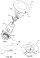
- Figure 4 illustrates, in an exploded view, one embodiment of a burr hole plug 450 that includes a base 452, two lead retention members 454a, 454b, a locking member 456, a cover 458, a fastener 460, and an optional fastener holder 462.
- Figures 5A and 5B illustrate the assembled burr hole plug 450 (which does not include the optional fastener holder 462).
- the burr hole plug 450 can have a low profile of 3 mm or less above the skull.
- the base 452 and cap 458 of the burr hole plug may be smooth and flexible and follow the curvature of the skull to reduce or prevent skin erosion and infection.
- the burr hole plug includes only a single exit 459 for the lead to reduce the edges of the burr hole plug.
- the single exit 459 can be rotated around the skull prior to fastening the base 452 and placing the cover 458 to a desired exit direction or position.
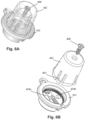
- Figure 6A illustrates one embodiment of components of the burr hole plug 450 as packaged prior to use.
- Figure 6B illustrates the removal of the optional fastener holder 462 and fastener 460.
- the fastener holder 462 is primarily provided to avoid misplacing the fastener 460 and may also be provided to hold components such as the two lead retention members 454a, 454b and the locking member 456 in the base 452 prior to use. In this manner, the small components of the burr hole plug 450 are not misplaced or lost.
- the fastener holder 462 fits into the base 452, as illustrated in Figure 6A and includes fingers 463 that can be engaged or compressed within the base 452 to retain the fastener holder in the base.
- the fastener 460 such as a screw
- the fastener holder 462 can be made of any suitable material including, but not limited to, rigid plastics, thermoplastics, metal, or any combination thereof and, in some embodiments, may be transparent or translucent.
- the base 452 fits within a burr hole made in the skull of a patient.
- Figures 6B , 7A, and 7B illustrate one embodiment of a base 452 that has a flange 464 which may rest on the skull and a sidewall 466 that extends into the burr hole and defines a burr hole aperture 465 ( Figure 4 ).
- the base 452 includes a gap 467 for receiving a portion of the lead as the base 452 is slid onto or into the burr hole after the lead has been implanted, if desired.
- the flange 464 includes one or more tabs 468, each tab 468 having an opening 469 to receive the fastener 460 to secure the base 452 to the skull of the patient. It will be understood that other fastening arrangements can also be used.
- the base 452 can be made of any suitable material including, but not limited to, plastic, metal, ceramic, or any combination thereof.
- at least the flange 464 has some flexibility to conform with the shape of the skull on which it rests.
- the sidewall 466 forms a friction or compression fit with the burr hole in which it is placed.
- the interior portion of the sidewall 466 of the base 452 includes an engagement region 470 with vertical teeth 471 (e.g., alternating ridges and valleys).
- the teeth 471 of the engagement region 470 engage corresponding teeth on the locking member 456, as described below, to prevent or hinder the locking member 456 and lead retention members 454a, 454b from rotating within the base 452 after the locking member 456 is placed.
- the interior portion of the sidewall 466 of the base 452 may also include a bottom ridge 472 ( Figure 4 ) upon which the lead retention members 454a, 454b fit when placed in the base.
- the interior portion of the sidewall 466 of the base 452 may also include a shoulder 461 connecting the flange 464 to the remainder of the sidewall and arranged to fit, for example, in a countersunk portion of the burr hole.
- the shoulder 461 and flange 464 may define a detent 473 for receiving a ridge of the cover 458.
- each lead retention member 454a, 454b has a form of less than half of a cylinder having an outer diameter equal to, or slightly less than, an inner diameter of the base 452.
- each lead retention member 454a, 454b has a main body 474, a lead engagement surface 476, an optional curved rotation limiting element 478, a receiving opening 480, and a circumferential groove 482.
- the lead retention member 454a, 454b is positioned in the base 452, the ridge 472 ( Figure 4 ) of the base fits into the circumferential groove 482 to hold the lead retention members within the base.
- the lead retention members 454a, 454b prior to insertion of the locking member 456, can rotate within the base 452.
- the lead retention members 454a, 454b can also swivel with respect to each other.
- Figure 7A illustrates the lead retention members 454a, 454b disposed within the base 452 prior to the insertion of the locking member 456.
- the separation between the lead engagement surfaces 476 of the two lead retention members 454a, 454b is constrained by either engagement of the main bodies 474 or the curved rotation limiting elements 478 or a combination of both, as illustrated in Figure 8B .
- a portion 475 of the main bodies 474 of the lead retention members 454a, 454b is inset relative to a remaining portion 477 to receive the locking member 456.
- the lead engagement surfaces 476 of the lead retention members 454a, 454b preferably include surface elements, such as the illustrated vertical teeth 479, that can engage and securely hold a lead in place between the two lead engagement surfaces and prevent or reduce slippage of the lead relative to the burr hole plug 450. Examples of other surface elements include, but are not limited to, roughened surfaces, horizontal teeth, diagonal or other non-vertical teeth, a pattern of peaked elements, or the like, or any combination thereof.
- Figure 9 illustrates one embodiment of a tool 484 that can be used to manipulate, rotate, and swivel the lead retention members 454a, 454b. Additionally or alternatively, the tool 484 can be used to manipulate or insert the locking member 456.
- the tool 484 is a pair of tweezers with small pins 486 on the tips that can fit within the receiving openings 480 of the lead retention members 454a, 454b and also in receiving openings 491 ( Figure 10A ) in the locking member 456.
- the tool 484 can engage one or both of the lead retention members 454a, 454b, for example, with a pin 486 in the corresponding receiving opening 480, and then rotate or swivel one or both of the lead retention elements 454a, 454b.
- FIGS 10A-10C illustrate one embodiment of a locking member 456.
- the locking member 456 can be made of any suitable material including, but not limited to, plastic, metal, ceramic, or any combination thereof.
- the locking member 456 includes a body 488, two pins 490, a wedge element 492, and a retention element 494.
- the pins 490 extend from the body 488 and are configured to fit within the openings 480 in the lead retention members 454a, 454b.
- the wedge element 492 also fits between the two lead retention members 454a, 454b to separate, and properly position, the two lead retention members and drive the lead engagement surfaces 476 toward each other to grip the lead between the two lead engagement surfaces in a lead engagement position.
- the wedge element 492 optionally includes one or more sloped bottom surfaces 493 to facilitate inserting the wedge element 492 between the two lead retention members 454a, 454b and separating the two lead retention members from each other.
- the retention element 494 includes teeth 495 for engaging the teeth 471 of the engagement region 470 of the base 452. This engagement between the teeth 495 of the retention element 494 and teeth 471 of the engagement region 470 prevents the locking member 456 and lead retention members 454a, 454b from rotating within the base 452 when the locking member 456 is inserted into the base 452. This arrangement facilitates maintaining the lead in the same position.
- Figure 7B illustrates the lead retention members 454a, 454b and locking member 456 disposed within the base 452.
- FIGs 11A and 11B illustrate the cover 458 which also defines an opening 459 for exit of the lead.
- the cover 458 is preferably made of a soft material such as silicone and preferably is smooth and flexible. Flexibility of the cover 458 may facilitate following the curvature of the skull of the patient and reduce tissue erosion and reduce the height of the burr hole plug, as illustrated in Figure 12 .
- the cover 458 covers the entire base 452. In at least some embodiments, the cover 458 provides a gentle, tapering slope to reduce or prevent tissue erosion.
- the cover 458 may include a skirt 496 that fits around the outer perimeter of the base 452 including the tab 468 (see, e.g., Figures 7A-7B ) to fit firmly on the base 452, a rim or ridge 498 that fits inside the sidewall 466, an inset region 497 between the skirt 496 and the rim corresponding to a shape of the flange 464 of the base 452, and a center region 499.
- the rim 498 fits into a detent 473 formed by the sidewall 466 of the base 452 and may facilitate retention of the cover 458 on the base 452.
- the insert region 464 allows the cover 458 and base 452 to have a low profile as the cover fits onto the base with relatively small increase in the extension of the burr hole plug above the skull relative to the base alone.
Landscapes
- Health & Medical Sciences (AREA)
- Life Sciences & Earth Sciences (AREA)
- Engineering & Computer Science (AREA)
- Biomedical Technology (AREA)
- Nuclear Medicine, Radiotherapy & Molecular Imaging (AREA)
- Animal Behavior & Ethology (AREA)
- General Health & Medical Sciences (AREA)
- Public Health (AREA)
- Veterinary Medicine (AREA)
- Neurosurgery (AREA)
- Neurology (AREA)
- Radiology & Medical Imaging (AREA)
- Psychology (AREA)
- Heart & Thoracic Surgery (AREA)
- Surgery (AREA)
- Cardiology (AREA)
- Oral & Maxillofacial Surgery (AREA)
- Molecular Biology (AREA)
- Medical Informatics (AREA)
- Pathology (AREA)
- Electrotherapy Devices (AREA)
Description
- The present disclosure is also directed to burr hole plugs and implantable electrical stimulation systems including the burr hole plugs.
- Implantable electrical stimulation systems have proven therapeutic in a variety of diseases and disorders. For example, stimulation of the brain, such as deep brain stimulation, can be used to treat a variety of diseases or disorders, and spinal cord stimulation systems have been used as a therapeutic modality for the treatment of chronic pain syndromes. Peripheral nerve stimulation has been used to treat incontinence, as well as a number of other applications under investigation. Functional electrical stimulation systems have been applied to restore some functionality to paralyzed extremities in spinal cord injury patients.
- Stimulators have been developed to provide therapy for a variety of treatments. A stimulator can include a control module (with a pulse generator), one or more leads, and an array of stimulator electrodes on each lead. The stimulator electrodes are in contact with or near the brain, nerves, or other tissue to be stimulated. The pulse generator in the control module generates electrical pulses that are delivered by the electrodes to body tissue.
-
US 2004/0034367 A1 discloses a cranial burr hole plug with an insertion tool and method of implantation. The burr hole plug includes a shell, a collet interlocked within the shell, a clamp compressing the collet around an elongated medical device exiting the skull of a patient, such as a catheter or lead, and a cover over the clamp, collet, and shell. -
US 2014/0243945 A1 discloses a burr hole plug that comprises a plug base configured for being mounted around a burr hole, and having an aperture through which an elongated medical device exiting the burr hole may pass. The burr hole plug further comprises a retainer configured for being mounted within the plug base aperture. The retainer includes a retainer support, a slot formed in the retainer support for receiving the medical device, and a clamping mechanism having a clamping bar and a flange slidably engaged with the retainer support to laterally slide the clamping bar to secure the medical device. - The invention is defined by the burr hole plug of claim 1 and the system for electrical stimulation comprising such a burr hole plug of claim 14. Further aspects and preferred embodiments are defined in the appended claims. Aspects, embodiments and examples of the present disclosure which do not fall under the scope of the appended claims do not form part of the invention and are merely provided for illustrative purposes. Furthermore, the methods presented in the present description are provided for illustrative purposes only and do not form part of the present invention.
- Non-limiting and non-exhaustive embodiments of the present invention are described with reference to the following drawings. In the drawings, like reference numerals refer to like parts throughout the various figures unless otherwise specified.
- For a better understanding of the present invention, reference will be made to the following Detailed Description, which is to be read in association with the accompanying drawings, wherein:
-
FIG. 1 is a schematic view of one embodiment of an electrical stimulation system; -
FIG. 2 is a schematic side view of one embodiment of an electrical stimulation lead; -
FIG. 3 is a schematic overview of one embodiment of components of a stimulation system, including an electronic subassembly disposed within a control module; -
FIG. 4 is an exploded perspective view of components of one embodiment of a burr hole plug; -
FIG. 5A is a perspective top view of the assembled burr hole plug ofFIG. 4 ; -
FIG. 5B is a perspective bottom view of the assembled burr hole plug ofFIG. 4 ; -
FIG. 6A is a perspective side view of one embodiment of some of the components of the burr hole plug ofFIG. 4 including a fastener holder; -
FIG. 6B is a perspective exploded view of one embodiment of some of the components of the burr hole plug ofFIG. 4 including a fastener holder; -
FIG. 7A is a perspective view of one embodiment of the base and lead retention elements of the burr hole plug ofFIG. 4 ; -
FIG. 7B is a perspective view of one embodiment of the base, lead retention elements, and locking element of the burr hole plug ofFIG. 4 ; -
FIG. 8A is a perspective view of one embodiment of the lead retention elements of the burr hole plug ofFIG. 4 ; -
FIG. 8B is a perspective view of the lead retention elements of the burr hole plug ofFIG. 4 engaged with each other; -
FIG. 9 is a perspective view and detail view of a tool for use with the lead retention element ofFIGS. 8A and 8B and the locking member ofFIGS. 7B ,10A, 10B, and 10C ; -
FIG. 10A is a perspective top-front view of one embodiment of a locking member of the burr hole plug ofFIG. 4 ; -
FIG. 10B is a perspective top-back view of one embodiment of a locking member of the burr hole plug ofFIG. 4 ; -
FIG. 10C is a perspective bottom view of one embodiment of a locking member of the burr hole plug ofFIG. 4 ; -
FIG. 11A is a perspective top view of one embodiment of a cover of the burr hole plug ofFIG. 4 ; -
FIG. 11B is a perspective bottom view of one embodiment of a cover of the burr hole plug ofFIG. 4 ; and -
FIG. 12 is an image of a burr hole plug fixed in a skull. - The present disclosure is directed to the area of implantable electrical stimulation systems. The present disclosure is also directed to burr hole plugs and implantable electrical stimulation systems including the burr hole plugs.
- Suitable implantable electrical stimulation systems include, but are not limited to, a least one lead with one or more electrodes disposed on a distal portion of the lead and one or more terminals disposed on one or more proximal portions of the lead. Leads include, for example, percutaneous leads, paddle leads, cuff leads, or any other arrangement of electrodes on a lead. Examples of electrical stimulation systems with leads are found in, for example,
U.S. Patents Nos. 6,181,969 ;6,516,227 ;6,609,029 ;6,609,032 ;6,741,892 ;7,244,150 ;7,450,997 ;7,672,734 ;7,761,165 ;7,783,359 ;7,792,590 ;7,809,446 ;7,949,395 ;7,974,706 ;8,175,710 ;8,224,450 ;8,271,094 ;8,295,944 ;8,364,278 ;8,391,985 ; and8,688,235 ; andU.S. Patent Applications Publication Nos. 2007/0150036 ;2009/0187222 ;2009/0276021 ;2010/0076535 ;2010/0268298 ;2011/0005069 ;2011/0004267 ;2011/0078900 ;2011/0130817 ;2011/0130818 ;2011/0238129 ;2011/0313500 ;2012/0016378 ;2012/0046710 ;2012/0071949 ;2012/0165911 ;2012/0197375 ;2012/0203316 ;2012/0203320 ;2012/0203321 ;2012/0316615 ;2013/0105071 ; and2013/0197602 . In the discussion below, a percutaneous lead will be exemplified, but it will be understood that the systems described herein are also applicable to paddle leads and other leads. - A percutaneous lead for electrical stimulation (for example, deep brain, spinal cord, peripheral nerve, or cardiac-tissue) includes stimulation electrodes that can be ring electrodes, segmented electrodes that extend only partially around the circumference of the lead, or any other type of electrode, or any combination thereof. The segmented electrodes can be provided in sets of electrodes, with each set having electrodes circumferentially distributed about the lead at a particular longitudinal position. A set of segmented electrodes can include any suitable number of electrodes including, for example, two, three, four, or more electrodes. For illustrative purposes, the leads are described herein relative to use for deep brain stimulation, but it will be understood that such leads can be used for applications other than deep brain stimulation, including spinal cord stimulation, peripheral nerve stimulation, dorsal root ganglion stimulation, sacral nerve stimulation, or stimulation of other nerves, muscles, and tissues.
- Turning to
Figure 1 , one embodiment of an electrical stimulation system 10 includes one or more stimulation leads 12 and an implantable pulse generator (IPG) 14. The system 10 can also include one or more of an external remote control (RC) 16, a clinician's programmer (CP) 18, an external trial stimulator (ETS) 20, or an external charger 22. - The IPG 14 is physically connected, optionally, via one or more
lead extensions 24, to the stimulation lead(s) 12. Each lead carriesmultiple electrodes 26 arranged in an array. The IPG 14 includes pulse generation circuitry that delivers electrical stimulation energy in the form of, for example, a pulsed electrical waveform (i.e., a temporal series of electrical pulses) to theelectrode array 26 in accordance with a set of stimulation parameters. The implantable pulse generator can be implanted into a patient's body, for example, below the patient's clavicle area or within the patient's abdominal cavity. The implantable pulse generator can have eight stimulation channels which may be independently programmable to control the magnitude of the current stimulus from each channel. In some embodiments, the implantable pulse generator can have more or fewer than eight stimulation channels (e.g., 4-, 6-, 16-, 32-, or more stimulation channels). The implantable pulse generator can have one, two, three, four, or more connector ports, for receiving the terminals of the leads and/or lead extensions. - The ETS 20 may also be physically connected, optionally via the
percutaneous lead extensions 28 and external cable 30, to the stimulation leads 12. The ETS 20, which may have similar pulse generation circuitry as the IPG 14, also delivers electrical stimulation energy in the form of, for example, a pulsed electrical waveform to theelectrode array 26 in accordance with a set of stimulation parameters. One difference between the ETS 20 and the IPG 14 is that the ETS 20 is often a non-implantable device that is used on a trial basis after the neurostimulation leads 12 have been implanted and prior to implantation of the IPG 14, to test the responsiveness of the stimulation that is to be provided. Any functions described herein with respect to the IPG 14 can likewise be performed with respect to the ETS 20. - The RC 16 may be used to telemetrically communicate with or control the IPG 14 or ETS 20 via a uni- or bi-directional wireless communications link 32. Once the IPG 14 and neurostimulation leads 12 are implanted, the RC 16 may be used to telemetrically communicate with or control the IPG 14 via a uni- or bi-directional communications link 34. Such communication or control allows the IPG 14 to be turned on or off and to be programmed with different stimulation parameter sets. The IPG 14 may also be operated to modify the programmed stimulation parameters to actively control the characteristics of the electrical stimulation energy output by the IPG 14. The CP 18 allows a user, such as a clinician, the ability to program stimulation parameters for the IPG 14 and ETS 20 in the operating room and in follow-up sessions. Alternately, or additionally, stimulation parameters can be programed via wireless communications (e.g., Bluetooth) between the RC 16 (or external device such as a hand-held electronic device) and the IPG 14.
- The CP 18 may perform this function by indirectly communicating with the IPG 14 or ETS 20, through the RC 16, via a wireless communications link 36. Alternatively, the CP 18 may directly communicate with the IPG 14 or ETS 20 via a wireless communications link (not shown). The stimulation parameters provided by the CP 18 are also used to program the RC 16, so that the stimulation parameters can be subsequently modified by operation of the RC 16 in a stand-alone mode (i.e., without the assistance of the CP 18).
- For purposes of brevity, the details of the RC 16, CP 18, ETS 20, and external charger 22 will not be further described herein. Details of exemplary embodiments of these devices are disclosed in
U.S. Pat. No. 6,895,280 . Other examples of electrical stimulation systems can be found atU.S. Patents Nos. 6,181,969 ;6,516,227 ;6,609,029 ;6,609,032 ;6,741,892 ;7,949,395 ;7,244,150 ;7,672,734 ;7,761,165 ;7,974,706 ;8,175,710 ;8,224,450 ; and8,364,278 ; andU.S. Patent Application Publication No. 2007/0150036 , as well as the other references cited above. - Turning to
Figure 2 , one or more leads are configured for coupling with a control module. The term "control module" is used herein to describe a pulse generator (e.g., the IPG 14 or the ETS 20 ofFigure 1 ). Stimulation signals generated by the control module are emitted by electrodes of the lead(s) to stimulate patient tissue. The electrodes of the lead(s) are electrically coupled to terminals of the lead(s) that, in turn, are electrically coupleable with the control module. In some embodiments, the lead(s) couple(s) directly with the control module. In other embodiments, one or more intermediary devices (e.g., a lead extension, an adaptor, a splitter, or the like) are disposed between the lead(s) and the control module. - Percutaneous leads are described herein for clarity of illustration. It will be understood that paddle leads and cuff leads can be used in lieu of, or in addition to, percutaneous leads. The leads described herein include 8 electrodes. It will be understood that the leads could include any suitable number of electrodes. The leads can include ring electrode, a distal-tip electrode, or one or more segmented electrodes, or any combination thereof. Additionally, the term "elongated member" used herein includes leads (e.g., percutaneous, paddle, cuff, or the like), as well as intermediary devices (e.g., lead extensions, adaptors, splitters, or the like).
-
Figure 2 illustrates one embodiment of a lead 100 withelectrodes 125 disposed at least partially about a circumference of thelead 100 along a distal end portion of the lead andterminals 135 disposed along a proximal end portion of the lead. Thelead 100 can be implanted near or within the desired portion of the body to be stimulated such as, for example, the brain, spinal cord, or other body organs or tissues. In one example of operation for deep brain stimulation, access to the desired position in the brain can be accomplished by drilling a hole in the patient's skull or cranium with a cranial drill (commonly referred to as a burr), and coagulating and incising the dura mater, or brain covering. Thelead 100 can be inserted into the cranium and brain tissue with the assistance of a stylet (not shown). Thelead 100 can be guided to the target location within the brain using, for example, a stereotactic frame and a microdrive motor system. In some embodiments, the microdrive motor system can be fully or partially automatic. The microdrive motor system may be configured to perform one or more the following actions (alone or in combination): insert thelead 100, advance thelead 100, retract thelead 100, or rotate thelead 100. - The
lead 100 for deep brain stimulation can include stimulation electrodes, recording electrodes, or both. In at least some embodiments, thelead 100 is rotatable so that the stimulation electrodes can be aligned with the target neurons after the neurons have been located using the recording electrodes. - Stimulation electrodes may be disposed on the circumference of the
lead 100 to stimulate the target neurons. Stimulation electrodes may be ring-shaped so that current projects from each electrode equally in every direction from the position of the electrode along a length of thelead 100. In the embodiment ofFigure 2 , two of theelectrodes 125 arering electrodes 120.Ring electrodes 120 typically do not enable stimulus current to be directed from only a limited angular range around of the lead.Segmented electrodes 130, however, can be used to direct stimulus current to a selected angular range around thelead 100. When segmentedelectrodes 130 are used in conjunction with an implantable pulse generator that delivers constant current stimulus, current steering can be achieved to more precisely deliver the stimulus to a position around an axis of the lead (i.e., radial positioning around the axis of the lead 100). To achieve current steering,segmented electrodes 130 can be utilized in addition to, or as an alternative to, ringelectrodes 120. - As described above, the
lead 100 includes alead body 110,terminals 135, and one ormore ring electrodes 120 and one or more sets of segmented electrodes 130 (or any other combination of electrodes). Thelead body 100 can be formed of a biocompatible, non-conducting material such as, for example, a polymeric material. Suitable polymeric materials include, but are not limited to, silicone, polyurethane, polyurea, polyurethane-urea, polyethylene, or the like. Once implanted in the body, thelead 100 may be in contact with body tissue for extended periods of time. In at least some embodiments, thelead 100 has a cross-sectional diameter of no more than 1.5 mm and may be in the range of 0.5 to 1.5 mm. In at least some embodiments, thelead 100 has a length of at least 10 cm and the length of thelead 100 may be in the range of 10 to 70 cm. - The
electrodes 125 can be made using a metal, alloy, conductive oxide, or any other suitable conductive biocompatible material. Examples of suitable materials include, but are not limited to, platinum, platinum iridium alloy, iridium, titanium, tungsten, palladium, palladium rhodium, or the like. Preferably, the electrodes are made of a material that is biocompatible and does not substantially corrode under expected operating conditions in the operating environment for the expected duration of use. - Each of the electrodes can either be used (ON) or unused (OFF). When the electrode is used, the electrode can be used as an anode or cathode and carry anodic or cathodic current. In some instances, an electrode might be an anode for a period of time and a cathode for a period of time.
- As described above, deep brain stimulation leads and other leads may include one or more sets of segmented electrodes. Segmented electrodes may provide for superior current steering than ring electrodes because target structures in deep brain stimulation are not typically symmetric about the axis of the distal electrode array. Instead, a target may be located on one side of a plane running through the axis of the lead. Through the use of a radially segmented electrode array ("RSEA"), current steering can be performed not only along a length of the lead but also around a circumference of the lead. This provides precise three-dimensional targeting and delivery of the current stimulus to neural target tissue, while potentially avoiding stimulation of other tissue. Examples of leads with segmented electrodes include
U.S. Patents Nos. 8,473,061 ;8,571,665 ; and8,792,993 ;U.S. Patent Application Publications Nos. 2010/0268298 ;2011/0005069 ;2011/0130803 ;2011/0130816 ;2011/0130817 ;2011/0130818 ;2011/0078900 ;2011/0238129 ;2012/0016378 ;2012/0046710 ;2012/0071949 ;2012/0165911 ;2012/197375 ;2012/0203316 ;2012/0203320 ;2012/0203321 ;2013/0197424 ;2013/0197602 ;2014/0039587 ;2014/0353001 ;2014/0358208 ;2014/0358209 ;2014/0358210 ;2015/0045864 ;2015/0066120 ;2015/0018915 ;2015/0051681 ;2015/0151113 ;2014/0358207 ; and2016/0228692 . Segmented electrodes can also be used for other stimulation techniques including, but not limited to, spinal cord stimulation, peripheral nerve stimulation, dorsal root ganglion stimulation, or stimulation of other nerves, muscles, and tissues. -
Figure 3 is a schematic overview of one embodiment of components of anelectrical stimulation system 300 including anelectronic subassembly 358 disposed within a control module. Theelectronic subassembly 358 may include one or more components of the IPG. It will be understood that the electrical stimulation system can include more, fewer, or different components and can have a variety of different configurations including those configurations disclosed in the stimulator references cited herein. - Some of the components (for example, a
power source 312, one ormore antennas 318, areceiver 302, and a processor 304) of the electrical stimulation system can be positioned on one or more circuit boards or similar carriers within a sealed electronics housing of an implantable pulse generator (see e.g., 14 inFigure 1 ), if desired. Anypower source 312 can be used including, for example, a battery such as a primary battery or a rechargeable battery. Examples of other power sources include super capacitors, nuclear or atomic batteries, mechanical resonators, infrared collectors, thermally-powered energy sources, flexural powered energy sources, bioenergy power sources, fuel cells, bioelectric cells, osmotic pressure pumps, and the like including the power sources described inU.S. Patent No. 7,437,193 . - As another alternative, power can be supplied by an external power source through inductive coupling via the
optional antenna 318 or a secondary antenna. In at least some embodiments, the antenna 318 (or the secondary antenna) is implemented using the auxiliary electrically-conductive conductor. The external power source can be in a device that is mounted on the skin of the user or in a unit that is provided near the user on a permanent or periodic basis. - If the
power source 312 is a rechargeable battery, the battery may be recharged using theoptional antenna 318, if desired. Power can be provided to the battery for recharging by inductively coupling the battery through the antenna to arecharging unit 316 external to the user. Examples of such arrangements can be found in the references identified above. Theelectronic subassembly 358 and, optionally, thepower source 312 can be disposed within a control module (e.g., the IPG 14 or the ETS 20 ofFigure 1 ). - In one embodiment, electrical stimulation signals are emitted by the electrodes (e.g.,
electrode array 26 inFigure 1 ) to stimulate nerve fibers, muscle fibers, or other body tissues near the electrical stimulation system. Theprocessor 304 is generally included to control the timing and electrical characteristics of the electrical stimulation system. For example, theprocessor 304 can, if desired, control one or more of the timing, frequency, strength, duration, and waveform of the pulses. In addition, theprocessor 304 can select which electrodes can be used to provide stimulation, if desired. In some embodiments, theprocessor 304 selects which electrode(s) are cathodes and which electrode(s) are anodes. In some embodiments, theprocessor 304 is used to identify which electrodes provide the most useful stimulation of the desired tissue. - Various processors can be used and may be an electronic device that, for example, produces pulses at a regular interval or the processor can be capable of receiving and interpreting instructions from an
external programming unit 308 that, for example, allows modification of pulse characteristics. In the illustrated embodiment, theprocessor 304 is coupled to areceiver 302 which, in turn, is coupled to theoptional antenna 318. This allows theprocessor 304 to receive instructions from an external source to, for example, direct the pulse characteristics and the selection of electrodes, if desired. - In one embodiment, the
antenna 318 is capable of receiving signals (e.g., RF signals) from anexternal telemetry unit 306 which is programmed by theprogramming unit 308. Theprogramming unit 308 can be external to, or part of, thetelemetry unit 306. Thetelemetry unit 306 can be a device that is worn on the skin of the user or can be carried by the user and can have a form similar to a pager, cellular phone, or remote control, if desired. As another alternative, thetelemetry unit 306 may not be worn or carried by the user but may only be available at a home station or at a clinician's office. Theprogramming unit 308 can be any unit that can provide information to thetelemetry unit 306 for transmission to theelectrical stimulation system 300. Theprogramming unit 308 can be part of thetelemetry unit 306 or can provide signals or information to thetelemetry unit 306 via a wireless or wired connection. One example of asuitable programming unit 308 is a computer operated by the user or clinician to send signals to thetelemetry unit 306. - The signals sent to the
processor 304 via theantenna 318 and thereceiver 302 can be used to modify or otherwise direct the operation of the electrical stimulation system. For example, the signals may be used to modify the pulses of the electrical stimulation system such as modifying one or more of pulse duration, pulse frequency, pulse waveform, and pulse strength. The signals may also direct theelectrical stimulation system 300 to cease operation, to start operation, to start charging the battery, or to stop charging the battery. In other embodiments, the stimulation system does not include theantenna 318 orreceiver 302 and theprocessor 304 operates as programmed. - Optionally, the
electrical stimulation system 300 may include a transmitter (not shown) coupled to theprocessor 304 and theantenna 318 for transmitting signals back to thetelemetry unit 306 or another unit capable of receiving the signals. For example, theelectrical stimulation system 300 may transmit signals indicating whether theelectrical stimulation system 300 is operating properly or not or indicating when the battery needs to be charged or the level of charge remaining in the battery. Theprocessor 304 may also be capable of transmitting information about the pulse characteristics so that a user or clinician can determine or verify the characteristics. - In at least some instances of electrical stimulation of the brain, when a lead is implanted into the brain of a patient, the lead is inserted through a burr hole in the skull of the patient. The lead extends out of the burr hole and is coupled to a control module implanted elsewhere, for example, in the torso of the patient. A burr hole plug is provided in the burr hole to cover the opening through the skull, to protect the lead exiting the skull, and to firmly hold the lead in place to prevent or reduce lead migration within the brain.
- Conventional burr hole plugs may present challenges with respect to a number of factors including lead retention, softness, flexibility, and profile. Many conventional burr hole plugs may be considered unduly large, tall, high-profile, or unappealing. Many conventional burr hole plugs may not adequately hold the lead in place and prevent movement or shifting which may alter the position of the lead within the brain of the patient. Some conventional burr hole plugs force the lead to bend at a right angle at the exit without any protection which makes the lead vulnerable to fracture or short circuiting. During placement of many conventional burr hole plugs, the exiting lead may move from its precise target site in the brain. After placement of many conventional burr hole plugs, even a slight bending or deflection of the lead may cause repositioning of the lead. Also, a lead, not secured properly, may migrate over time and could require additional surgical procedures to correct. In addition, sharp edges of a burr hole plug base or cover can contribute to skin erosion, which can result in open lesions and eventually infection.
- A burr hole plug can be designed to address one or more of these concerns.
Figure 4 illustrates, in an exploded view, one embodiment of aburr hole plug 450 that includes abase 452, twolead retention members member 456, acover 458, afastener 460, and anoptional fastener holder 462.Figures 5A and 5B illustrate the assembled burr hole plug 450 (which does not include the optional fastener holder 462). In at least some embodiments, theburr hole plug 450 can have a low profile of 3 mm or less above the skull. In at least some embodiments, thebase 452 and cap 458 of the burr hole plug may be smooth and flexible and follow the curvature of the skull to reduce or prevent skin erosion and infection. In at least some embodiments, only asingle fastener 460 is used for attachment to the skill. In at least some embodiments, the burr hole plug includes only asingle exit 459 for the lead to reduce the edges of the burr hole plug. Thesingle exit 459 can be rotated around the skull prior to fastening thebase 452 and placing thecover 458 to a desired exit direction or position. -
Figure 6A illustrates one embodiment of components of theburr hole plug 450 as packaged prior to use.Figure 6B illustrates the removal of theoptional fastener holder 462 andfastener 460. Thefastener holder 462 is primarily provided to avoid misplacing thefastener 460 and may also be provided to hold components such as the twolead retention members member 456 in thebase 452 prior to use. In this manner, the small components of theburr hole plug 450 are not misplaced or lost. Thefastener holder 462 fits into thebase 452, as illustrated inFigure 6A and includesfingers 463 that can be engaged or compressed within thebase 452 to retain the fastener holder in the base. Thefastener 460, such as a screw, can be removed from thefastener holder 462 using a tool, such as a screw driver. Thefastener holder 462 can be made of any suitable material including, but not limited to, rigid plastics, thermoplastics, metal, or any combination thereof and, in some embodiments, may be transparent or translucent. - The base 452 fits within a burr hole made in the skull of a patient.
Figures 6B ,7A, and 7B illustrate one embodiment of a base 452 that has aflange 464 which may rest on the skull and asidewall 466 that extends into the burr hole and defines a burr hole aperture 465 (Figure 4 ). Optionally, thebase 452 includes agap 467 for receiving a portion of the lead as thebase 452 is slid onto or into the burr hole after the lead has been implanted, if desired. Theflange 464 includes one ormore tabs 468, eachtab 468 having anopening 469 to receive thefastener 460 to secure the base 452 to the skull of the patient. It will be understood that other fastening arrangements can also be used. - The base 452 can be made of any suitable material including, but not limited to, plastic, metal, ceramic, or any combination thereof. In some embodiments, at least the
flange 464 has some flexibility to conform with the shape of the skull on which it rests. In at least some embodiments, thesidewall 466 forms a friction or compression fit with the burr hole in which it is placed. - The interior portion of the
sidewall 466 of thebase 452 includes anengagement region 470 with vertical teeth 471 (e.g., alternating ridges and valleys). Theteeth 471 of theengagement region 470 engage corresponding teeth on the lockingmember 456, as described below, to prevent or hinder the lockingmember 456 andlead retention members base 452 after the lockingmember 456 is placed. The interior portion of thesidewall 466 of the base 452 may also include a bottom ridge 472 (Figure 4 ) upon which thelead retention members sidewall 466 of the base 452 may also include ashoulder 461 connecting theflange 464 to the remainder of the sidewall and arranged to fit, for example, in a countersunk portion of the burr hole. Theshoulder 461 andflange 464 may define adetent 473 for receiving a ridge of thecover 458. -
Figures 8A and 8B illustrate one embodiment of the twolead retention members lead retention members lead retention member base 452. In the illustrated embodiment, eachlead retention member main body 474, alead engagement surface 476, an optional curvedrotation limiting element 478, a receivingopening 480, and acircumferential groove 482. - In at least some embodiments, the
lead retention member base 452, the ridge 472 (Figure 4 ) of the base fits into thecircumferential groove 482 to hold the lead retention members within the base. In at least some embodiments, prior to insertion of the lockingmember 456, thelead retention members base 452. Thelead retention members Figure 7A illustrates thelead retention members base 452 prior to the insertion of the lockingmember 456. - The separation between the
lead engagement surfaces 476 of the twolead retention members main bodies 474 or the curvedrotation limiting elements 478 or a combination of both, as illustrated inFigure 8B . In at least some embodiments, aportion 475 of themain bodies 474 of thelead retention members portion 477 to receive the lockingmember 456. Thelead engagement surfaces 476 of thelead retention members vertical teeth 479, that can engage and securely hold a lead in place between the two lead engagement surfaces and prevent or reduce slippage of the lead relative to theburr hole plug 450. Examples of other surface elements include, but are not limited to, roughened surfaces, horizontal teeth, diagonal or other non-vertical teeth, a pattern of peaked elements, or the like, or any combination thereof. -
Figure 9 illustrates one embodiment of atool 484 that can be used to manipulate, rotate, and swivel thelead retention members tool 484 can be used to manipulate or insert the lockingmember 456. In the illustrated embodiment ofFigure 9 , thetool 484 is a pair of tweezers withsmall pins 486 on the tips that can fit within the receivingopenings 480 of thelead retention members Figure 10A ) in the lockingmember 456. In operation, thetool 484 can engage one or both of thelead retention members pin 486 in the corresponding receivingopening 480, and then rotate or swivel one or both of thelead retention elements -
Figures 10A-10C illustrate one embodiment of a lockingmember 456. The lockingmember 456 can be made of any suitable material including, but not limited to, plastic, metal, ceramic, or any combination thereof. In the illustrated embodiment, the lockingmember 456 includes abody 488, twopins 490, awedge element 492, and aretention element 494. - The
pins 490 extend from thebody 488 and are configured to fit within theopenings 480 in thelead retention members wedge element 492 also fits between the twolead retention members lead engagement surfaces 476 toward each other to grip the lead between the two lead engagement surfaces in a lead engagement position. Thewedge element 492 optionally includes one or more sloped bottom surfaces 493 to facilitate inserting thewedge element 492 between the twolead retention members - The
retention element 494 includesteeth 495 for engaging theteeth 471 of theengagement region 470 of thebase 452. This engagement between theteeth 495 of theretention element 494 andteeth 471 of theengagement region 470 prevents the lockingmember 456 andlead retention members base 452 when the lockingmember 456 is inserted into thebase 452. This arrangement facilitates maintaining the lead in the same position.Figure 7B illustrates thelead retention members member 456 disposed within thebase 452. -
Figures 11A and 11B illustrate thecover 458 which also defines anopening 459 for exit of the lead. Thecover 458 is preferably made of a soft material such as silicone and preferably is smooth and flexible. Flexibility of thecover 458 may facilitate following the curvature of the skull of the patient and reduce tissue erosion and reduce the height of the burr hole plug, as illustrated inFigure 12 . In at least some embodiments, thecover 458 covers theentire base 452. In at least some embodiments, thecover 458 provides a gentle, tapering slope to reduce or prevent tissue erosion. - In at least some embodiments, the
cover 458 may include askirt 496 that fits around the outer perimeter of the base 452 including the tab 468 (see, e.g.,Figures 7A-7B ) to fit firmly on thebase 452, a rim orridge 498 that fits inside thesidewall 466, aninset region 497 between theskirt 496 and the rim corresponding to a shape of theflange 464 of thebase 452, and acenter region 499. In at least some embodiments, therim 498 fits into adetent 473 formed by thesidewall 466 of thebase 452 and may facilitate retention of thecover 458 on thebase 452. In at least some embodiments, theinsert region 464 allows thecover 458 andbase 452 to have a low profile as the cover fits onto the base with relatively small increase in the extension of the burr hole plug above the skull relative to the base alone.
Claims (14)
- A burr hole plug (450), comprising:a base (452) defining a burr hole aperture (465) and comprising a flange (464) configured to rest on the skull of a patient, a sidewall (466) configured to extend into a burr hole in the skull of the patient, and an engagement region (470) extending around the sidewall;two lead retention members (454a, 454b) configured for placement within the base, each of the lead retention members comprising a lead engagement surface (476) to engage and hold a lead between the two lead retention members, wherein each of the lead retention members comprises a receiving opening (480);a locking member (456) configured for placement within the base and for engaging the two lead retention members to lock the two lead retention members in a lead engagement position and for engaging the engagement region of the base to prevent rotation of the two lead retention members within the base, wherein the locking member comprises two pins (490) configured for insertion in the receiving openings of the two lead retention members to lock the two lead retention members in the lead engagement position, wherein the locking member further comprises a wedge element (492) configured for insertion between the two lead retention members to separate the two lead retention members and drive the lead engagement surfaces of the two lead retention members toward each other; anda cover (458) configured to be disposed over, and coupled to, the base.
- The burr hole plug of claim 1, wherein the flange of the base defines at least one fastener opening (469).
- The burr hole plug of claim 2, wherein the cover is configured to be disposed entirely over, and coupled to, the base, wherein the flexible cover comprises a skirt (496) configured to fit around an outer perimeter of the base and a rim (498) that fits inside the sidewall of the base, wherein between the skirt and the rim is an inset region (497) having a shape corresponding to a shape of the flange of the base.
- The burr hole plug of any one of claims 1-3, wherein the engagement region of the base comprises a plurality of teeth (471) and the locking member comprises a retention element having a plurality of teeth (495) to engage the teeth of the engagement region of the base to prevent rotation of the locking element and the two lead retention members within the base.
- The burr hole plug of any one of claims 1-4, wherein the base comprises a ridge (472) around the sidewall and each of the lead retention members comprises a circumferential groove (482) that is configured to receive the ridge of the base.
- The burr hole plug of any one of claims 1-5, wherein each of the lead retention members comprises a curved rotation limiting element (478), wherein, absent the locking member, the two lead retention members are configured to swivel within the base limited, at least in part, by the curved rotation limiting elements.
- The burr hole plug of any one of claims 1-6, wherein the lead engagement surface of each of the two lead retention members comprises a plurality of vertical teeth (479) for securely holding the lead.
- The burr hole plug of any one of claims 1-7, wherein the base defines a gap (467) for receiving at least a portion of the lead.
- The burr hole plug of any one of claims 1-8, further comprising a fastener (460) and a fastener holder (462) for safely holding the fastener prior to removal for insertion in the skull to fasten the base to the skull.
- The burr hole plug of claim 9, wherein the fastener holder comprises a plurality of fingers (463) configured for compression when inserted in the base to retain the fastener holder within the base.
- The burr hole plug of any one of claims 1-10, wherein the base comprises a single fastener opening (469) for receiving a single fastener (460) to fasten the base to the skull.
- The burr hole plug of any one of claims 1-11, wherein the cover is made of silicone.
- The burr hole plug of any one of claims 1-12, wherein the cover comprises an opening (459) for exit of the lead.
- A system for electrical stimulation, comprising:the burr hole plug of any one of claims 1-13, andan electrical stimulation lead configured for insertion into the skull and for engagement with the burr hole plug.
Applications Claiming Priority (2)
| Application Number | Priority Date | Filing Date | Title |
|---|---|---|---|
| US201862641180P | 2018-03-09 | 2018-03-09 | |
| PCT/US2019/020670 WO2019173281A1 (en) | 2018-03-09 | 2019-03-05 | Burr hole plugs for electrical stimulation systems |
Publications (2)
| Publication Number | Publication Date |
|---|---|
| EP3762087A1 EP3762087A1 (en) | 2021-01-13 |
| EP3762087B1 true EP3762087B1 (en) | 2023-04-26 |
Family
ID=65818629
Family Applications (1)
| Application Number | Title | Priority Date | Filing Date |
|---|---|---|---|
| EP19712360.7A Active EP3762087B1 (en) | 2018-03-09 | 2019-03-05 | Burr hole plugs for electrical stimulation systems |
Country Status (3)
| Country | Link |
|---|---|
| US (1) | US11058870B2 (en) |
| EP (1) | EP3762087B1 (en) |
| WO (1) | WO2019173281A1 (en) |
Families Citing this family (2)
| Publication number | Priority date | Publication date | Assignee | Title |
|---|---|---|---|---|
| WO2021102780A1 (en) * | 2019-11-28 | 2021-06-03 | 苏州景昱医疗器械有限公司 | Auxiliary tool for surgery |
| CN114832233B (en) * | 2022-06-29 | 2022-09-27 | 苏州景昱医疗器械有限公司 | Cranial hole electrode fixing device |
Family Cites Families (240)
| Publication number | Priority date | Publication date | Assignee | Title |
|---|---|---|---|---|
| US2521301A (en) | 1950-09-05 | Morrison | ||
| US979652A (en) | 1910-03-11 | 1910-12-27 | Standard Electric Fittings Company | Gas connection for outlet-boxes. |
| US2186277A (en) | 1938-11-21 | 1940-01-09 | Gen Motors Corp | Grommet seal |
| US2873822A (en) | 1954-02-03 | 1959-02-17 | Cushman Chuck Co | Bolt-type locking mechanisms for indexing devices |
| US2912712A (en) | 1955-10-31 | 1959-11-17 | William S Shamban | One-piece grommet |
| DE2130221A1 (en) | 1971-06-18 | 1972-12-21 | Philips Nv | Piezoelectric ignition device |
| FR2193955B1 (en) | 1972-07-28 | 1975-03-07 | Genoud & Cie Ets | |
| JPS5153906Y2 (en) | 1972-09-14 | 1976-12-23 | ||
| GB1554332A (en) | 1976-06-10 | 1979-10-17 | Matsushita Electric Ind Co Ltd | High voltage generating device |
| US4114603A (en) | 1976-08-06 | 1978-09-19 | Wilkinson Harold A | Intracranial pressure monitoring catheter |
| CA1065969A (en) | 1977-09-28 | 1979-11-06 | Gratien Bouillon | Self-blocking cerebral catheter |
| JPS55112538A (en) | 1979-02-23 | 1980-08-30 | Hitachi Ltd | Local overheat diagnostic unit of rotary electric machine |
| JPS5740541Y2 (en) | 1979-04-06 | 1982-09-06 | ||
| US4328313A (en) | 1979-12-19 | 1982-05-04 | The United States Of America As Represented By The Secretary Of The Navy | Method of producing a plaque dispersing enzyme |
| US4328813A (en) | 1980-10-20 | 1982-05-11 | Medtronic, Inc. | Brain lead anchoring system |
| US4467800A (en) | 1982-04-16 | 1984-08-28 | Medtronic, Inc. | Tool for creating a pocket for a epidural electrode |
| US4805615A (en) | 1985-07-02 | 1989-02-21 | Carol Mark P | Method and apparatus for performing stereotactic surgery |
| EP0248103A1 (en) | 1986-06-06 | 1987-12-09 | Hellige GmbH | Adapter for exchangeably implanting bio-sensors in the skull bone |
| US4741571A (en) | 1986-12-15 | 1988-05-03 | Dura Corporation | Manually foldable top for automobile vehicles |
| US4826487A (en) | 1987-05-04 | 1989-05-02 | Victory Engineering Company | Alignment button for stereotaxic plug and method of using the same |
| US4931056A (en) | 1987-09-04 | 1990-06-05 | Neurodynamics, Inc. | Catheter guide apparatus for perpendicular insertion into a cranium orifice |
| US4850359A (en) | 1987-10-16 | 1989-07-25 | Ad-Tech Medical Instrument Corporation | Electrical brain-contact devices |
| US4998938A (en) | 1988-06-09 | 1991-03-12 | Neurodynamics, Inc. | Removable skull mounted work platform and method of assembling same |
| US5116345A (en) | 1990-11-28 | 1992-05-26 | Ohio Medical Instrument Co., Inc. | Stereotactically implanting an intracranial device |
| DE4111856C1 (en) | 1991-04-11 | 1992-07-16 | Oswald Leibinger Gmbh, 7202 Muehlheim, De | |
| US5235990A (en) | 1991-06-28 | 1993-08-17 | Dempsey Robert N | Apparatus for neutralizing irritants introduced into a body via a bite or sting |
| JPH0511600A (en) | 1991-07-06 | 1993-01-22 | Fujitsu Ltd | Electrostatic recorder using one-component developer |
| US5330485A (en) | 1991-11-01 | 1994-07-19 | Clayman David A | Cerebral instrument guide frame and procedures utilizing it |
| US5300080A (en) | 1991-11-01 | 1994-04-05 | David Clayman | Stereotactic instrument guided placement |
| US5193540A (en) | 1991-12-18 | 1993-03-16 | Alfred E. Mann Foundation For Scientific Research | Structure and method of manufacture of an implantable microstimulator |
| US5193539A (en) | 1991-12-18 | 1993-03-16 | Alfred E. Mann Foundation For Scientific Research | Implantable microstimulator |
| BR9305925A (en) | 1992-02-20 | 1997-08-26 | Humanteknik Ab | Device for vacuum affixing an object to a surface electrode unit and absorber for a vacuum electrode assembly |
| US6356777B1 (en) | 1992-12-22 | 2002-03-12 | Schering Aktiengesellschaft | Methods of and apparatus for activating the muscle cells or nerves of the uterus or cervix |
| US5496356A (en) | 1993-03-29 | 1996-03-05 | Hudz; Paul H. | Piezo de-toxifier |
| US5464446A (en) | 1993-10-12 | 1995-11-07 | Medtronic, Inc. | Brain lead anchoring system |
| US5484445A (en) | 1993-10-12 | 1996-01-16 | Medtronic, Inc. | Sacral lead anchoring system |
| WO1995018642A1 (en) | 1994-01-07 | 1995-07-13 | Omar Omirana | Adhesive surgical retaining device |
| US5503164A (en) | 1994-01-28 | 1996-04-02 | Osteogenics, Inc. | Device and method for repair of craniomaxillofacial bone defects including burr holes |
| SE9402339D0 (en) | 1994-07-01 | 1994-07-01 | Humanteknik Ab | Transition element for a biomedical electrode |
| US5549620A (en) | 1994-12-06 | 1996-08-27 | Bremer; Paul | Brain surgery with craniotomy pin |
| US5954687A (en) | 1995-04-28 | 1999-09-21 | Medtronic, Inc. | Burr hole ring with catheter for use as an injection port |
| US5927277A (en) | 1995-04-28 | 1999-07-27 | Medtronic, Inc. | Method and apparatus for securing probes within a burr hole |
| US6944501B1 (en) | 2000-04-05 | 2005-09-13 | Neurospace, Inc. | Neurostimulator involving stimulation strategies and process for using it |
| US6480743B1 (en) | 2000-04-05 | 2002-11-12 | Neuropace, Inc. | System and method for adaptive brain stimulation |
| US20020169485A1 (en) | 1995-10-16 | 2002-11-14 | Neuropace, Inc. | Differential neurostimulation therapy driven by physiological context |
| US6073048A (en) | 1995-11-17 | 2000-06-06 | Medtronic, Inc. | Baroreflex modulation with carotid sinus nerve stimulation for the treatment of heart failure |
| IT1281688B1 (en) | 1996-01-19 | 1998-02-26 | Tecnica S R L | PORTABLE TOOL TO TREAT INSECT BITS |
| US6463328B1 (en) | 1996-02-02 | 2002-10-08 | Michael Sasha John | Adaptive brain stimulation method and system |
| US5707373A (en) | 1996-04-26 | 1998-01-13 | Ikonos Corporation | Bone fastener and instrument for insertion thereof |
| US6094598A (en) | 1996-04-25 | 2000-07-25 | Medtronics, Inc. | Method of treating movement disorders by brain stimulation and drug infusion |
| DE19618945C2 (en) | 1996-05-10 | 2003-02-27 | Phonak Ag Staefa | Fixable positioning system for a firm, play-free connection to the human skull |
| US5865842A (en) | 1996-08-29 | 1999-02-02 | Medtronic, Inc. | System and method for anchoring brain stimulation lead or catheter |
| US5984930A (en) | 1996-09-30 | 1999-11-16 | George S. Allen | Biopsy guide |
| EP0942967A1 (en) | 1996-11-06 | 1999-09-22 | Children's Medical Center Corporation | Transgenic animal expressing a syndecan in the regions of hypothalamus |
| US6128537A (en) | 1997-05-01 | 2000-10-03 | Medtronic, Inc | Techniques for treating anxiety by brain stimulation and drug infusion |
| US5993463A (en) | 1997-05-15 | 1999-11-30 | Regents Of The University Of Minnesota | Remote actuation of trajectory guide |
| CA2296632A1 (en) | 1997-07-16 | 1999-01-28 | Impulse Dynamics (Israel) Ltd. | Smooth muscle controller |
| US5843150A (en) | 1997-10-08 | 1998-12-01 | Medtronic, Inc. | System and method for providing electrical and/or fluid treatment within a patient's brain |
| US6354299B1 (en) | 1997-10-27 | 2002-03-12 | Neuropace, Inc. | Implantable device for patient communication |
| US6647296B2 (en) | 1997-10-27 | 2003-11-11 | Neuropace, Inc. | Implantable apparatus for treating neurological disorders |
| US6459936B2 (en) | 1997-10-27 | 2002-10-01 | Neuropace, Inc. | Methods for responsively treating neurological disorders |
| US6230049B1 (en) | 1999-08-13 | 2001-05-08 | Neuro Pace, Inc. | Integrated system for EEG monitoring and electrical stimulation with a multiplicity of electrodes |
| US6597954B1 (en) | 1997-10-27 | 2003-07-22 | Neuropace, Inc. | System and method for controlling epileptic seizures with spatially separated detection and stimulation electrodes |
| US6427086B1 (en) | 1997-10-27 | 2002-07-30 | Neuropace, Inc. | Means and method for the intracranial placement of a neurostimulator |
| US6016449A (en) | 1997-10-27 | 2000-01-18 | Neuropace, Inc. | System for treatment of neurological disorders |
| US7033367B2 (en) | 1998-04-14 | 2006-04-25 | Neurodynamics, Inc. | Slotted catheter guide for perpendicular insertion into a cranium orifice |
| US5916154A (en) | 1998-04-22 | 1999-06-29 | Nellcor Puritan Bennett | Method of enhancing performance in pulse oximetry via electrical stimulation |
| US6050098A (en) | 1998-04-29 | 2000-04-18 | American Standard Inc. | Use of electronic expansion valve to maintain minimum oil flow |
| US6044304A (en) | 1998-04-29 | 2000-03-28 | Medtronic, Inc. | Burr ring with integral lead/catheter fixation device |
| US6374140B1 (en) | 1998-04-30 | 2002-04-16 | Medtronic, Inc. | Method and apparatus for treating seizure disorders by stimulating the olfactory senses |
| US6319241B1 (en) | 1998-04-30 | 2001-11-20 | Medtronic, Inc. | Techniques for positioning therapy delivery elements within a spinal cord or a brain |
| US6006124A (en) | 1998-05-01 | 1999-12-21 | Neuropace, Inc. | Means and method for the placement of brain electrodes |
| US6224450B1 (en) | 1998-08-28 | 2001-05-01 | Laurie J. Norton | Cycling activity belt |
| WO2000000251A1 (en) | 1998-06-26 | 2000-01-06 | Advanced Bionics Corporation | Programmable current output stimulus stage for implantable device |
| US6171239B1 (en) | 1998-08-17 | 2001-01-09 | Emory University | Systems, methods, and devices for controlling external devices by signals derived directly from the nervous system |
| US6200329B1 (en) | 1998-08-31 | 2001-03-13 | Smith & Nephew, Inc. | Suture collet |
| US6482182B1 (en) | 1998-09-03 | 2002-11-19 | Surgical Navigation Technologies, Inc. | Anchoring system for a brain lead |
| US6117143A (en) | 1998-09-11 | 2000-09-12 | Hybex Surgical Specialties, Inc. | Apparatus for frameless stereotactic surgery |
| US6269270B1 (en) | 1998-10-26 | 2001-07-31 | Birinder Bob Boveja | Apparatus and method for adjunct (add-on) therapy of Dementia and Alzheimer's disease utilizing an implantable lead and external stimulator |
| US8244370B2 (en) | 2001-04-13 | 2012-08-14 | Greatbatch Ltd. | Band stop filter employing a capacitor and an inductor tank circuit to enhance MRI compatibility of active medical devices |
| US6321104B1 (en) | 1998-11-05 | 2001-11-20 | Medtronic, Inc. | Burr hole cap for fixation of cranial lead |
| US6393325B1 (en) | 1999-01-07 | 2002-05-21 | Advanced Bionics Corporation | Directional programming for implantable electrode arrays |
| US6464687B1 (en) | 1999-03-09 | 2002-10-15 | Ball Semiconductor, Inc. | Implantable drug delivery system |
| US6356729B1 (en) | 1999-04-07 | 2002-03-12 | Ricoh Company, Ltd. | Electrophotographic toner, toner container containing the toner, image forming apparatus using the toner container and method for supplying the toner from the toner container |
| US6126663A (en) | 1999-04-15 | 2000-10-03 | Hair; John Hunter | Expandable bone connector |
| US6491699B1 (en) | 1999-04-20 | 2002-12-10 | Surgical Navigation Technologies, Inc. | Instrument guidance method and system for image guided surgery |
| US6210417B1 (en) | 1999-04-29 | 2001-04-03 | Medtronic, Inc. | Medical lead positioning and anchoring system |
| US6353762B1 (en) | 1999-04-30 | 2002-03-05 | Medtronic, Inc. | Techniques for selective activation of neurons in the brain, spinal cord parenchyma or peripheral nerve |
| US6134477A (en) | 1999-04-30 | 2000-10-17 | Medtronic, Inc. | Adjustable medical lead fixation system |
| US6050998A (en) | 1999-05-21 | 2000-04-18 | Stephen A. Fletcher | Bone fastener |
| US6516227B1 (en) | 1999-07-27 | 2003-02-04 | Advanced Bionics Corporation | Rechargeable spinal cord stimulator system |
| US6574498B1 (en) | 1999-09-16 | 2003-06-03 | Super Dimension Ltd. | Linking of an intra-body tracking system to external reference coordinates |
| US7949395B2 (en) | 1999-10-01 | 2011-05-24 | Boston Scientific Neuromodulation Corporation | Implantable microdevice with extended lead and remote electrode |
| US6560486B1 (en) | 1999-10-12 | 2003-05-06 | Ivan Osorio | Bi-directional cerebral interface system |
| US6391985B1 (en) | 1999-10-21 | 2002-05-21 | Union Carbide Chemicals & Plastics Technology Corporation | High condensing mode polyolefin production under turbulent conditions in a fluidized bed |
| TW468807U (en) | 1999-11-05 | 2001-12-11 | Hon Hai Prec Ind Co Ltd | Fixed stand for the computer host |
| GB9928248D0 (en) | 1999-12-01 | 2000-01-26 | Gill Steven S | An implantable guide tube for neurosurgery |
| US6447443B1 (en) | 2001-01-13 | 2002-09-10 | Medtronic, Inc. | Method for organ positioning and stabilization |
| US6324433B1 (en) * | 2000-01-20 | 2001-11-27 | Electrocare Technologies, Llc | Electrode-lead coupling skull mounted port assembly |
| US6356792B1 (en) | 2000-01-20 | 2002-03-12 | Electro Core Technologies, Llc | Skull mounted electrode lead securing assembly |
| US6628976B1 (en) | 2000-01-27 | 2003-09-30 | Biosense Webster, Inc. | Catheter having mapping assembly |
| US6609029B1 (en) | 2000-02-04 | 2003-08-19 | Advanced Bionics Corporation | Clip lock mechanism for retaining lead |
| US6271094B1 (en) | 2000-02-14 | 2001-08-07 | International Business Machines Corporation | Method of making MOSFET with high dielectric constant gate insulator and minimum overlap capacitance |
| US6920359B2 (en) | 2000-02-15 | 2005-07-19 | Advanced Bionics Corporation | Deep brain stimulation system for the treatment of Parkinson's Disease or other disorders |
| US6741892B1 (en) | 2000-03-10 | 2004-05-25 | Advanced Bionics Corporation | Movable contact locking mechanism for spinal cord stimulator lead connector |
| US6466822B1 (en) | 2000-04-05 | 2002-10-15 | Neuropace, Inc. | Multimodal neurostimulator and process of using it |
| US7660621B2 (en) | 2000-04-07 | 2010-02-09 | Medtronic, Inc. | Medical device introducer |
| US6413263B1 (en) | 2000-04-24 | 2002-07-02 | Axon Instruments, Inc. | Stereotactic probe holder and method of use |
| US6295944B1 (en) | 2000-06-20 | 2001-10-02 | J Timothy Lovett | Automatic tethering system for a floating dock |
| US6845267B2 (en) | 2000-09-28 | 2005-01-18 | Advanced Bionics Corporation | Systems and methods for modulation of circulatory perfusion by electrical and/or drug stimulation |
| US6950707B2 (en) | 2000-11-21 | 2005-09-27 | Advanced Bionics Corporation | Systems and methods for treatment of obesity and eating disorders by electrical brain stimulation and/or drug infusion |
| US6618623B1 (en) | 2000-11-28 | 2003-09-09 | Neuropace, Inc. | Ferrule for cranial implant |
| US7212867B2 (en) | 2000-12-07 | 2007-05-01 | Medtronic, Inc. | Directional brain stimulation and recording leads |
| US7177701B1 (en) | 2000-12-29 | 2007-02-13 | Advanced Bionics Corporation | System for permanent electrode placement utilizing microelectrode recording methods |
| US7033326B1 (en) | 2000-12-29 | 2006-04-25 | Advanced Bionics Corporation | Systems and methods of implanting a lead for brain stimulation |
| US7004948B1 (en) | 2001-01-31 | 2006-02-28 | Advanced Bionics Corporation | Cranial sealing plug |
| WO2003026738A1 (en) | 2001-09-28 | 2003-04-03 | Northstar Neuroscience, Inc. | Methods and apparatus for electrically stimulating cells implanted in the nervous system |
| IL145700A0 (en) | 2001-09-30 | 2002-06-30 | Younis Imad | Electrode system for neural applications |
| US7010356B2 (en) | 2001-10-31 | 2006-03-07 | London Health Sciences Centre Research Inc. | Multichannel electrode and methods of using same |
| US6859667B2 (en) | 2001-11-07 | 2005-02-22 | Cardiac Pacemakers, Inc. | Multiplexed medical device lead with standard header |
| WO2003063951A1 (en) | 2002-01-29 | 2003-08-07 | Advanced Bionics Corporation | Lead assembly for implantable microstimulator |
| US7050855B2 (en) | 2002-01-29 | 2006-05-23 | Medtronic, Inc. | Medical implantable system for reducing magnetic resonance effects |
| EP1478348A4 (en) | 2002-02-01 | 2008-06-18 | Cleveland Clinic Foundation | Microinfusion device |
| US7118828B2 (en) | 2002-03-11 | 2006-10-10 | Quallion Llc | Implantable battery |
| US7146222B2 (en) | 2002-04-15 | 2006-12-05 | Neurospace, Inc. | Reinforced sensing and stimulation leads and use in detection systems |
| US20030199831A1 (en) | 2002-04-23 | 2003-10-23 | Morris Mary M. | Catheter anchor system and method |
| US7120992B2 (en) | 2002-06-28 | 2006-10-17 | Advanced Bionics Corporation | Method of making an electronic module |
| US7479146B2 (en) | 2002-08-14 | 2009-01-20 | Boston Scientific Neuromodulation Corporation | Cranial burr hole plug and insertion tool |
| US7343205B1 (en) | 2002-08-20 | 2008-03-11 | Boston Scientific Neuromodulation Corp. | System and method for insertion of a device into the brain |
| US7704260B2 (en) * | 2002-09-17 | 2010-04-27 | Medtronic, Inc. | Low profile instrument immobilizer |
| US20050075679A1 (en) | 2002-09-30 | 2005-04-07 | Gliner Bradford E. | Methods and apparatuses for treating neurological disorders by electrically stimulating cells implanted in the nervous system |
| US20050010261A1 (en) | 2002-10-21 | 2005-01-13 | The Cleveland Clinic Foundation | Application of stimulus to white matter to induce a desired physiological response |
| US20050075680A1 (en) | 2003-04-18 | 2005-04-07 | Lowry David Warren | Methods and systems for intracranial neurostimulation and/or sensing |
| EP1578497B1 (en) | 2002-12-09 | 2010-04-21 | Medtronic, Inc. | Low-profile implantable medical device |
| US7636596B2 (en) | 2002-12-20 | 2009-12-22 | Medtronic, Inc. | Organ access device and method |
| WO2004084749A1 (en) | 2003-03-26 | 2004-10-07 | Mrc Systems Gmbh | Device for determining the position of a target region in the brain |
| US20050003268A1 (en) | 2003-05-16 | 2005-01-06 | Scott Erik R. | Battery housing configuration |
| US7263401B2 (en) | 2003-05-16 | 2007-08-28 | Medtronic, Inc. | Implantable medical device with a nonhermetic battery |
| US7454251B2 (en) | 2003-05-29 | 2008-11-18 | The Cleveland Clinic Foundation | Excess lead retaining and management devices and methods of using same |
| EP1510173B1 (en) | 2003-09-01 | 2017-04-05 | BIOTRONIK SE & Co. KG | Intracardial impedance measuring device |
| US7686780B2 (en) | 2003-09-26 | 2010-03-30 | New York University | System and method for correction of intracerebral chemical imbalances |
| WO2005039696A1 (en) | 2003-10-21 | 2005-05-06 | The Regents Of The University Of Michigan | Intracranial neural interface system |
| US7207454B2 (en) | 2003-10-29 | 2007-04-24 | Vinit Chantalat | Method and apparatus for sealing and re-sealing an annular vessel opening |
| US7981119B2 (en) | 2003-12-11 | 2011-07-19 | Advanced Neuromodulation Systems, Inc. | Electrical stimulation system and associated apparatus for securing an electrical stimulation lead in position in a person's brain |
| EP1722848A1 (en) | 2004-02-13 | 2006-11-22 | Medtronic, Inc. | Methods and apparatus for securing a therapy delivery device within a burr hole |
| US7174219B2 (en) | 2004-03-30 | 2007-02-06 | Medtronic, Inc. | Lead electrode for use in an MRI-safe implantable medical device |
| US7283856B2 (en) | 2004-04-09 | 2007-10-16 | Neuro Pace, Inc. | Implantable lead system with seed electrodes |
| EP1776040A4 (en) | 2004-08-09 | 2012-02-15 | Univ Johns Hopkins | Implantable mri compatible stimulation leads and antennas and related systems and methods |
| WO2006033110A2 (en) | 2004-09-24 | 2006-03-30 | Dov Ehrlich | Method and apparatus for treatment of tinnitus and other neurological disorders by brain stimulation in the inferior colliculi and/or in adjacent areas |
| US7682745B2 (en) | 2004-10-29 | 2010-03-23 | Medtronic, Inc. | Medical device having lithium-ion battery |
| US7341562B2 (en) | 2004-12-15 | 2008-03-11 | Neuropace, Inc. | Modulation and analysis of cerebral perfusion in epilepsy and other neurological disorders |
| US7783359B2 (en) | 2005-01-05 | 2010-08-24 | Boston Scientific Neuromodulation Corporation | Devices and methods using an implantable pulse generator for brain stimulation |
| US7809446B2 (en) | 2005-01-05 | 2010-10-05 | Boston Scientific Neuromodulation Corporation | Devices and methods for brain stimulation |
| US7369899B2 (en) | 2005-02-22 | 2008-05-06 | Boston Scientific Neuromodulation Corporation | Minimally invasive systems for locating an optimal location for deep brain stimulation |
| US8430888B2 (en) | 2005-02-22 | 2013-04-30 | Boston Scientific Neuromodulation Corporation | Minimally invasive methods for locating an optimal location for deep brain stimulation |
| US7421297B2 (en) | 2005-03-31 | 2008-09-02 | Medtronic, Inc. | Monopolar stimulation assembly including at least one remote electrode |
| CA2562205A1 (en) | 2005-09-28 | 2007-03-28 | Medtrode Inc. | Implantable transcranial pulse generator having a collapsible portion |
| US7761165B1 (en) | 2005-09-29 | 2010-07-20 | Boston Scientific Neuromodulation Corporation | Implantable stimulator with integrated plastic housing/metal contacts and manufacture and use |
| US8271094B1 (en) | 2005-09-30 | 2012-09-18 | Boston Scientific Neuromodulation Corporation | Devices with cannula and electrode lead for brain stimulation and methods of use and manufacture |
| US20070106143A1 (en) | 2005-11-08 | 2007-05-10 | Flaherty J C | Electrode arrays and related methods |
| US7853324B2 (en) | 2005-11-11 | 2010-12-14 | Greatbatch Ltd. | Tank filters utilizing very low K materials, in series with lead wires or circuits of active medical devices to enhance MRI compatibility |
| US8700178B2 (en) | 2005-12-27 | 2014-04-15 | Boston Scientific Neuromodulation Corporation | Stimulator leads and methods for lead fabrication |
| US7672734B2 (en) | 2005-12-27 | 2010-03-02 | Boston Scientific Neuromodulation Corporation | Non-linear electrode array |
| US7244150B1 (en) | 2006-01-09 | 2007-07-17 | Advanced Bionics Corporation | Connector and methods of fabrication |
| US7833253B2 (en) | 2006-01-17 | 2010-11-16 | Biodynamics Llc | Craniotomy closures and plugs |
| US7756922B2 (en) | 2006-01-27 | 2010-07-13 | Oracle International Corporation | Schema annotations for managing cached document fragments |
| US7787945B2 (en) | 2006-03-08 | 2010-08-31 | Neuropace, Inc. | Implantable seizure monitor |
| US8175710B2 (en) | 2006-03-14 | 2012-05-08 | Boston Scientific Neuromodulation Corporation | Stimulator system with electrode array and the method of making the same |
| US7974706B2 (en) | 2006-03-30 | 2011-07-05 | Boston Scientific Neuromodulation Corporation | Electrode contact configurations for cuff leads |
| US7949410B2 (en) | 2006-04-04 | 2011-05-24 | Advanced Neuromodulation Systems, Inc. | Burr hole cap and methods of use |
| US7766922B1 (en) | 2006-04-21 | 2010-08-03 | Advanced Neuromodulation Systems, Inc. | Burr hole caps and methods of use |
| US9084901B2 (en) | 2006-04-28 | 2015-07-21 | Medtronic, Inc. | Cranial implant |
| US8321025B2 (en) | 2006-07-31 | 2012-11-27 | Cranial Medical Systems, Inc. | Lead and methods for brain monitoring and modulation |
| US8224450B2 (en) | 2006-09-18 | 2012-07-17 | Boston Scientific Neuromodulation Corporation | Feed through interconnect assembly for an implantable stimulation system and methods of making and using |
| US7766394B2 (en) | 2006-10-30 | 2010-08-03 | Medtronic, Inc. | Breakaway connectors and systems |
| US8221479B2 (en) * | 2007-01-19 | 2012-07-17 | Pbj, Llc | Orthopedic screw insert |
| EP2131916A1 (en) | 2007-03-02 | 2009-12-16 | Koninklijke Philips Electronics N.V. | Electrode system for deep brain stimulation |
| WO2008107822A1 (en) | 2007-03-02 | 2008-09-12 | Koninklijke Philips Electronics N.V. | Electrode system for deep brain stimulation |
| US20080275466A1 (en) | 2007-05-01 | 2008-11-06 | James Grant Skakoon | Dual cannula system and method for using same |
| GB0719608D0 (en) | 2007-10-08 | 2007-11-14 | Renishaw Plc | Medical Apparatus |
| EP2540248B1 (en) | 2007-10-26 | 2015-11-25 | Boston Scientific Neuromodulation Corporation | Burr hole plug designs |
| US20090118804A1 (en) | 2007-11-05 | 2009-05-07 | Advanced Bionics Corporation | Method of mounting minimally invasive plug electrodes within cranium of patient |
| US8140173B2 (en) | 2007-12-12 | 2012-03-20 | Codman & Shurtleff, Inc. | Anchoring device for securing intracranial catheter or lead wire to a patient's skull |
| US8116873B2 (en) | 2007-12-28 | 2012-02-14 | Cvrx, Inc. | Measurement of patient physiological parameters |
| EP2242534B1 (en) | 2008-01-22 | 2014-01-08 | Medtronic, Inc. | Burr hole anchors and systems |
| US9192409B2 (en) | 2008-01-23 | 2015-11-24 | Boston Scientific Neuromodulation Corporation | Steerable stylet handle assembly |
| US8024045B2 (en) | 2008-02-08 | 2011-09-20 | Intelect Medical, Inc. | Multi-functional burr hole assembly |
| US20090202899A1 (en) | 2008-02-11 | 2009-08-13 | Pyszczek Michael F | Electrical apparatus with integral thin film solid state battery and methods of manufacture |
| US8600518B2 (en) | 2008-04-30 | 2013-12-03 | Boston Scientific Neuromodulation Corporation | Electrodes for stimulation leads and methods of manufacture and use |
| US8688235B1 (en) | 2008-07-22 | 2014-04-01 | Boston Scientific Neuromodulation Corporation | Lead with transition and methods of manufacture and use |
| US8043304B2 (en) * | 2008-07-24 | 2011-10-25 | Boston Scientific Neuromodulation Corporation | Cam lock burr hole plug for securing retainer/plug base |
| US8425534B2 (en) | 2008-07-24 | 2013-04-23 | Boston Scientific Neuromodulation Corporation | Cam lock burr hole plug for securing stimulation lead |
| US20100076535A1 (en) | 2008-09-25 | 2010-03-25 | Boston Scientific Neuromodulation Corporation | Leads with non-circular-shaped distal ends for brain stimulation systems and methods of making and using |
| US9393432B2 (en) | 2008-10-31 | 2016-07-19 | Medtronic, Inc. | Non-hermetic direct current interconnect |
| EP3520855B1 (en) | 2009-04-16 | 2024-05-29 | Boston Scientific Neuromodulation Corporation | Deep brain stimulation current steering with split electrodes |
| US8417353B2 (en) | 2009-04-29 | 2013-04-09 | Medtronic, Inc. | Method and apparatus for securing an electrode |
| US8887387B2 (en) | 2009-07-07 | 2014-11-18 | Boston Scientific Neuromodulation Corporation | Methods of manufacture of leads with a radially segmented electrode array |
| US8875391B2 (en) | 2009-07-07 | 2014-11-04 | Boston Scientific Neuromodulation Corporation | Methods for making leads with radially-aligned segmented electrodes for electrical stimulation systems |
| US8313453B2 (en) | 2009-08-27 | 2012-11-20 | Boston Scientific Neuromodulation Corporation | Burr hole sealing device for preventing brain shift |
| EP2493797B1 (en) | 2009-10-30 | 2021-05-19 | Nidec Vamco Corporation | Material feeding apparatus with gripping member linkage |
| US8391985B2 (en) | 2009-11-30 | 2013-03-05 | Boston Scientific Neuromodulation Corporation | Electrode array having concentric windowed cylinder electrodes and methods of making the same |
| US8295944B2 (en) | 2009-11-30 | 2012-10-23 | Boston Scientific Neuromodulation Corporation | Electrode array with electrodes having cutout portions and methods of making the same |
| US8874232B2 (en) | 2009-11-30 | 2014-10-28 | Boston Scientific Neuromodulation Corporation | Electrode array having concentric split ring electrodes and methods of making the same |
| US8788063B2 (en) | 2009-11-30 | 2014-07-22 | Boston Scientific Neuromodulation Corporation | Electrode array having a rail system and methods of manufacturing the same |
| WO2011119377A1 (en) | 2010-03-23 | 2011-09-29 | Boston Scientific Neuromodulation Corporation | Helical radial spacing of contacts on a cylindrical lead |
| EP2582425B1 (en) | 2010-06-18 | 2018-04-04 | Boston Scientific Neuromodulation Corporation | Method of making electrode array having embedded electrodes |
| WO2012009181A2 (en) | 2010-07-16 | 2012-01-19 | Boston Scientific Neuromodulation Corporation | Systems and methods for radial steering of electrode arrays |
| US20120046710A1 (en) | 2010-08-18 | 2012-02-23 | Boston Scientific Neuromodulation Corporation | Methods, systems, and devices for deep brain stimulation using helical movement of the centroid of stimulation |
| JP5808813B2 (en) | 2010-09-21 | 2015-11-10 | ボストン サイエンティフィック ニューロモデュレイション コーポレイション | Electrical stimulation lead and method for forming a lead for a stimulation device |
| US8862242B2 (en) | 2010-12-23 | 2014-10-14 | Boston Scientific Neuromodulation Corporation | Methods for making leads with segmented electrodes for electrical stimulation systems |
| US8700179B2 (en) | 2011-02-02 | 2014-04-15 | Boston Scientific Neuromodulation Corporation | Leads with spiral of helical segmented electrode arrays and methods of making and using the leads |
| JP6005667B2 (en) | 2011-02-08 | 2016-10-12 | ボストン サイエンティフィック ニューロモデュレイション コーポレイション | Lead having segment electrodes arranged in a spiral and method for making and using the lead |
| AU2012214497B2 (en) | 2011-02-08 | 2016-05-05 | Boston Scientific Neuromodulation Corporation | Leads with segmented electrodes for electrical stimulation systems |
| US20120203316A1 (en) | 2011-02-08 | 2012-08-09 | Boston Scientific Neuromodulation Corporation | Leads with segmented electrodes for electrical stimulation of planar regions and methods of making and using |
| AU2012268048B2 (en) | 2011-06-07 | 2016-07-21 | Boston Scientific Neuromodulation Corporation | Systems and methods for making and using improved leads for electrical stimulation systems |
| US9474896B2 (en) | 2011-06-08 | 2016-10-25 | Boston Scientific Neuromodulation Corporation | Strain relieved lead routing in burr hole plug for deep brain stimulation |
| US8812133B2 (en) | 2011-09-13 | 2014-08-19 | Boston Scientific Neuromodulation Corporation | Cranial burr hole plug with anti-skewing clamping mechanism |
| WO2013067369A1 (en) | 2011-11-02 | 2013-05-10 | Boston Scientific Neuromodulation Corporation | Systems and methods for making improved leads for electrical stimulation systems |
| WO2013112905A1 (en) | 2012-01-26 | 2013-08-01 | Boston Scientific Neuromodulation Corporation | Systems and methods for identifying the circumferential positioning of electrodes of leads for electrical stimulation systems |
| US9788952B2 (en) | 2012-05-10 | 2017-10-17 | Neuropace, Inc. | Burr hole covers and methods for using same |
| WO2013181519A2 (en) | 2012-06-01 | 2013-12-05 | Boston Scientific Neuromodulation Corporation | Leads with tip electrode for electrical stimulation systems and methods of making and using |
| US8897891B2 (en) | 2012-08-03 | 2014-11-25 | Boston Scientific Neuromodulation Corporation | Leads with electrode carrier for segmented electrodes and methods of making and using |
| US9468751B2 (en) | 2012-12-05 | 2016-10-18 | Medtronic, Inc. | Medical device anchoring apparatus |
| US9572973B2 (en) | 2013-03-10 | 2017-02-21 | Neuropace, Inc. | Recessed burr hole covers and methods for using the same |
| AU2014274413A1 (en) | 2013-05-31 | 2015-11-19 | Boston Scientific Neuromodulation Corporation | Segmented electrode leads formed from pre-electrodes with alignment features and mehods of making and using the leads |
| JP2016519984A (en) | 2013-05-31 | 2016-07-11 | ボストン サイエンティフィック ニューロモデュレイション コーポレイション | Segment electrode lead formed from a pre-electrode having a recess or a hole, and a method for manufacturing the same |
| WO2014193762A2 (en) | 2013-05-31 | 2014-12-04 | Boston Scientific Neuromodulation Corporation | Leads containing segmented electrodes with non-perpendicular legs and methods of making and using |
| EP3003468B1 (en) | 2013-05-31 | 2019-08-28 | Boston Scientific Neuromodulation Corporation | Methods for manufacturing segmented electrode leads using a removable ring and the leads formed thereby |
| AU2014274414A1 (en) | 2013-05-31 | 2015-11-19 | Boston Scientific Neuromodulation Corporation | Leads with segmented electrodes and methods of making the leads |
| JP6072986B2 (en) | 2013-07-12 | 2017-02-01 | ボストン サイエンティフィック ニューロモデュレイション コーポレイション | Lead having segment electrode and method of manufacturing and using lead |
| US9610437B2 (en) | 2013-08-01 | 2017-04-04 | University Of Florida Research Foundation, Inc. | Apparatuses and methods for securing deep brain stimulation leads |
| AU2014306085A1 (en) | 2013-08-07 | 2016-01-28 | Boston Scientific Neuromodulation Corporation | Systems and methods for making and using segmented tip electrodes for leads of electrical simulation systems |
| US20150051681A1 (en) | 2013-08-19 | 2015-02-19 | Boston Scientific Neuromodulation Corporation | Methods and systems for anodal stimulation to affect cranial and other nerves |
| WO2015031375A1 (en) | 2013-08-30 | 2015-03-05 | Boston Scientific Neuromodulation Corporation | Methods of making segmented electrode leads using flanged carrier |
| WO2015084745A1 (en) | 2013-12-02 | 2015-06-11 | Boston Scientific Neuromodulation Corporation | Electrical stimulation leads with helically arranged electrodes and methods for their manufacture |
| US9492660B2 (en) | 2014-12-09 | 2016-11-15 | Pacesetter, Inc. | Implantable neurostimulation systems and methods thereof |
| US10286205B2 (en) | 2015-02-06 | 2019-05-14 | Boston Scientific Neuromodulation Corporation | Systems and methods for making and using improved contact arrays for electrical stimulation systems |
| US10232169B2 (en) | 2015-07-23 | 2019-03-19 | Boston Scientific Neuromodulation Corporation | Burr hole plugs for electrical stimulation systems and methods of making and using |
| US10610681B2 (en) * | 2017-08-29 | 2020-04-07 | Medtronic Inc. | Medical device anchoring |
| CN111344042B (en) | 2017-11-13 | 2023-09-26 | 波士顿科学神经调制公司 | Systems and methods for manufacturing and using low profile control modules of an electrical stimulation system |
-
2019
- 2019-03-05 WO PCT/US2019/020670 patent/WO2019173281A1/en active Application Filing
- 2019-03-05 EP EP19712360.7A patent/EP3762087B1/en active Active
- 2019-03-05 US US16/292,682 patent/US11058870B2/en active Active
Also Published As
| Publication number | Publication date |
|---|---|
| US20190275317A1 (en) | 2019-09-12 |
| US11058870B2 (en) | 2021-07-13 |
| WO2019173281A1 (en) | 2019-09-12 |
| EP3762087A1 (en) | 2021-01-13 |
Similar Documents
| Publication | Publication Date | Title |
|---|---|---|
| US10286205B2 (en) | Systems and methods for making and using improved contact arrays for electrical stimulation systems | |
| US9839787B2 (en) | Systems and methods for making and using connector contact arrays for electrical stimulation systems | |
| US9833611B2 (en) | Systems and methods for making and using improved contact arrays for electrical stimulation systems | |
| US10814127B2 (en) | Slotted sleeve neurostimulation device | |
| EP3710105B1 (en) | Systems for making and using a low-profile control module for an electrical stimulation system | |
| US10232169B2 (en) | Burr hole plugs for electrical stimulation systems and methods of making and using | |
| EP3762087B1 (en) | Burr hole plugs for electrical stimulation systems | |
| EP3765142B1 (en) | Kit for securing burr hole plugs for stimulation systems | |
| US20190290924A1 (en) | Implantable prostheses for reducing visibility of bulging from implanted medical devices | |
| EP3946569B1 (en) | Low-profile control module for an electrical stimulation system | |
| US11497914B2 (en) | Systems and methods for making and using an electrical stimulation system with a case-neutral battery | |
| US11172959B2 (en) | Long, flexible sheath and lead blank and systems and methods of making and using | |
| US8849419B2 (en) | Systems and methods for making and using electrodes for enhancing stimulation penetration of patient tissue |
Legal Events
| Date | Code | Title | Description |
|---|---|---|---|
| STAA | Information on the status of an ep patent application or granted ep patent |
Free format text: STATUS: UNKNOWN |
|
| STAA | Information on the status of an ep patent application or granted ep patent |
Free format text: STATUS: THE INTERNATIONAL PUBLICATION HAS BEEN MADE |
|
| PUAI | Public reference made under article 153(3) epc to a published international application that has entered the european phase |
Free format text: ORIGINAL CODE: 0009012 |
|
| STAA | Information on the status of an ep patent application or granted ep patent |
Free format text: STATUS: REQUEST FOR EXAMINATION WAS MADE |
|
| 17P | Request for examination filed |
Effective date: 20201007 |
|
| AK | Designated contracting states |
Kind code of ref document: A1 Designated state(s): AL AT BE BG CH CY CZ DE DK EE ES FI FR GB GR HR HU IE IS IT LI LT LU LV MC MK MT NL NO PL PT RO RS SE SI SK SM TR |
|
| AX | Request for extension of the european patent |
Extension state: BA ME |
|
| DAV | Request for validation of the european patent (deleted) | ||
| DAX | Request for extension of the european patent (deleted) | ||
| GRAP | Despatch of communication of intention to grant a patent |
Free format text: ORIGINAL CODE: EPIDOSNIGR1 |
|
| STAA | Information on the status of an ep patent application or granted ep patent |
Free format text: STATUS: GRANT OF PATENT IS INTENDED |
|
| INTG | Intention to grant announced |
Effective date: 20221025 |
|
| GRAS | Grant fee paid |
Free format text: ORIGINAL CODE: EPIDOSNIGR3 |
|
| GRAA | (expected) grant |
Free format text: ORIGINAL CODE: 0009210 |
|
| STAA | Information on the status of an ep patent application or granted ep patent |
Free format text: STATUS: THE PATENT HAS BEEN GRANTED |
|
| AK | Designated contracting states |
Kind code of ref document: B1 Designated state(s): AL AT BE BG CH CY CZ DE DK EE ES FI FR GB GR HR HU IE IS IT LI LT LU LV MC MK MT NL NO PL PT RO RS SE SI SK SM TR |
|
| REG | Reference to a national code |
Ref country code: GB Ref legal event code: FG4D |
|
| REG | Reference to a national code |
Ref country code: CH Ref legal event code: EP |
|
| REG | Reference to a national code |
Ref country code: DE Ref legal event code: R096 Ref document number: 602019028031 Country of ref document: DE |
|
| REG | Reference to a national code |
Ref country code: AT Ref legal event code: REF Ref document number: 1562393 Country of ref document: AT Kind code of ref document: T Effective date: 20230515 |
|
| REG | Reference to a national code |
Ref country code: IE Ref legal event code: FG4D |
|
| REG | Reference to a national code |
Ref country code: LT Ref legal event code: MG9D |
|
| REG | Reference to a national code |
Ref country code: NL Ref legal event code: MP Effective date: 20230426 |
|
| REG | Reference to a national code |
Ref country code: AT Ref legal event code: MK05 Ref document number: 1562393 Country of ref document: AT Kind code of ref document: T Effective date: 20230426 |
|
| PG25 | Lapsed in a contracting state [announced via postgrant information from national office to epo] |
Ref country code: NL Free format text: LAPSE BECAUSE OF FAILURE TO SUBMIT A TRANSLATION OF THE DESCRIPTION OR TO PAY THE FEE WITHIN THE PRESCRIBED TIME-LIMIT Effective date: 20230426 |
|
| PG25 | Lapsed in a contracting state [announced via postgrant information from national office to epo] |
Ref country code: SE Free format text: LAPSE BECAUSE OF FAILURE TO SUBMIT A TRANSLATION OF THE DESCRIPTION OR TO PAY THE FEE WITHIN THE PRESCRIBED TIME-LIMIT Effective date: 20230426 Ref country code: PT Free format text: LAPSE BECAUSE OF FAILURE TO SUBMIT A TRANSLATION OF THE DESCRIPTION OR TO PAY THE FEE WITHIN THE PRESCRIBED TIME-LIMIT Effective date: 20230828 Ref country code: NO Free format text: LAPSE BECAUSE OF FAILURE TO SUBMIT A TRANSLATION OF THE DESCRIPTION OR TO PAY THE FEE WITHIN THE PRESCRIBED TIME-LIMIT Effective date: 20230726 Ref country code: ES Free format text: LAPSE BECAUSE OF FAILURE TO SUBMIT A TRANSLATION OF THE DESCRIPTION OR TO PAY THE FEE WITHIN THE PRESCRIBED TIME-LIMIT Effective date: 20230426 Ref country code: AT Free format text: LAPSE BECAUSE OF FAILURE TO SUBMIT A TRANSLATION OF THE DESCRIPTION OR TO PAY THE FEE WITHIN THE PRESCRIBED TIME-LIMIT Effective date: 20230426 |
|
| PG25 | Lapsed in a contracting state [announced via postgrant information from national office to epo] |
Ref country code: RS Free format text: LAPSE BECAUSE OF FAILURE TO SUBMIT A TRANSLATION OF THE DESCRIPTION OR TO PAY THE FEE WITHIN THE PRESCRIBED TIME-LIMIT Effective date: 20230426 Ref country code: PL Free format text: LAPSE BECAUSE OF FAILURE TO SUBMIT A TRANSLATION OF THE DESCRIPTION OR TO PAY THE FEE WITHIN THE PRESCRIBED TIME-LIMIT Effective date: 20230426 Ref country code: LV Free format text: LAPSE BECAUSE OF FAILURE TO SUBMIT A TRANSLATION OF THE DESCRIPTION OR TO PAY THE FEE WITHIN THE PRESCRIBED TIME-LIMIT Effective date: 20230426 Ref country code: LT Free format text: LAPSE BECAUSE OF FAILURE TO SUBMIT A TRANSLATION OF THE DESCRIPTION OR TO PAY THE FEE WITHIN THE PRESCRIBED TIME-LIMIT Effective date: 20230426 Ref country code: IS Free format text: LAPSE BECAUSE OF FAILURE TO SUBMIT A TRANSLATION OF THE DESCRIPTION OR TO PAY THE FEE WITHIN THE PRESCRIBED TIME-LIMIT Effective date: 20230826 Ref country code: HR Free format text: LAPSE BECAUSE OF FAILURE TO SUBMIT A TRANSLATION OF THE DESCRIPTION OR TO PAY THE FEE WITHIN THE PRESCRIBED TIME-LIMIT Effective date: 20230426 Ref country code: GR Free format text: LAPSE BECAUSE OF FAILURE TO SUBMIT A TRANSLATION OF THE DESCRIPTION OR TO PAY THE FEE WITHIN THE PRESCRIBED TIME-LIMIT Effective date: 20230727 |
|
| PG25 | Lapsed in a contracting state [announced via postgrant information from national office to epo] |
Ref country code: FI Free format text: LAPSE BECAUSE OF FAILURE TO SUBMIT A TRANSLATION OF THE DESCRIPTION OR TO PAY THE FEE WITHIN THE PRESCRIBED TIME-LIMIT Effective date: 20230426 |
|
| PG25 | Lapsed in a contracting state [announced via postgrant information from national office to epo] |
Ref country code: SK Free format text: LAPSE BECAUSE OF FAILURE TO SUBMIT A TRANSLATION OF THE DESCRIPTION OR TO PAY THE FEE WITHIN THE PRESCRIBED TIME-LIMIT Effective date: 20230426 |
|
| REG | Reference to a national code |
Ref country code: DE Ref legal event code: R097 Ref document number: 602019028031 Country of ref document: DE |
|
| PG25 | Lapsed in a contracting state [announced via postgrant information from national office to epo] |
Ref country code: SM Free format text: LAPSE BECAUSE OF FAILURE TO SUBMIT A TRANSLATION OF THE DESCRIPTION OR TO PAY THE FEE WITHIN THE PRESCRIBED TIME-LIMIT Effective date: 20230426 Ref country code: SK Free format text: LAPSE BECAUSE OF FAILURE TO SUBMIT A TRANSLATION OF THE DESCRIPTION OR TO PAY THE FEE WITHIN THE PRESCRIBED TIME-LIMIT Effective date: 20230426 Ref country code: RO Free format text: LAPSE BECAUSE OF FAILURE TO SUBMIT A TRANSLATION OF THE DESCRIPTION OR TO PAY THE FEE WITHIN THE PRESCRIBED TIME-LIMIT Effective date: 20230426 Ref country code: EE Free format text: LAPSE BECAUSE OF FAILURE TO SUBMIT A TRANSLATION OF THE DESCRIPTION OR TO PAY THE FEE WITHIN THE PRESCRIBED TIME-LIMIT Effective date: 20230426 Ref country code: DK Free format text: LAPSE BECAUSE OF FAILURE TO SUBMIT A TRANSLATION OF THE DESCRIPTION OR TO PAY THE FEE WITHIN THE PRESCRIBED TIME-LIMIT Effective date: 20230426 Ref country code: CZ Free format text: LAPSE BECAUSE OF FAILURE TO SUBMIT A TRANSLATION OF THE DESCRIPTION OR TO PAY THE FEE WITHIN THE PRESCRIBED TIME-LIMIT Effective date: 20230426 |
|
| PLBE | No opposition filed within time limit |
Free format text: ORIGINAL CODE: 0009261 |
|
| STAA | Information on the status of an ep patent application or granted ep patent |
Free format text: STATUS: NO OPPOSITION FILED WITHIN TIME LIMIT |
|
| 26N | No opposition filed |
Effective date: 20240129 |
|
| PGFP | Annual fee paid to national office [announced via postgrant information from national office to epo] |
Ref country code: DE Payment date: 20240220 Year of fee payment: 6 Ref country code: GB Payment date: 20240220 Year of fee payment: 6 |
|
| PG25 | Lapsed in a contracting state [announced via postgrant information from national office to epo] |
Ref country code: SI Free format text: LAPSE BECAUSE OF FAILURE TO SUBMIT A TRANSLATION OF THE DESCRIPTION OR TO PAY THE FEE WITHIN THE PRESCRIBED TIME-LIMIT Effective date: 20230426 |