EP3761092A2 - Ruggedized fiber optic connectors and connection systems - Google Patents
Ruggedized fiber optic connectors and connection systems Download PDFInfo
- Publication number
- EP3761092A2 EP3761092A2 EP20190363.0A EP20190363A EP3761092A2 EP 3761092 A2 EP3761092 A2 EP 3761092A2 EP 20190363 A EP20190363 A EP 20190363A EP 3761092 A2 EP3761092 A2 EP 3761092A2
- Authority
- EP
- European Patent Office
- Prior art keywords
- fiber optic
- connector
- ruggedized
- seal
- core
- Prior art date
- Legal status (The legal status is an assumption and is not a legal conclusion. Google has not performed a legal analysis and makes no representation as to the accuracy of the status listed.)
- Pending
Links
- 239000000835 fiber Substances 0.000 title claims abstract description 494
- 230000001681 protective effect Effects 0.000 claims abstract description 167
- 238000007789 sealing Methods 0.000 claims abstract description 121
- 239000013307 optical fiber Substances 0.000 claims description 34
- 238000004873 anchoring Methods 0.000 claims description 7
- 230000008878 coupling Effects 0.000 claims description 4
- 238000010168 coupling process Methods 0.000 claims description 4
- 238000005859 coupling reaction Methods 0.000 claims description 4
- 230000014759 maintenance of location Effects 0.000 description 11
- 230000000712 assembly Effects 0.000 description 8
- 238000000429 assembly Methods 0.000 description 8
- 239000000428 dust Substances 0.000 description 8
- 230000003287 optical effect Effects 0.000 description 8
- 230000006835 compression Effects 0.000 description 7
- 238000007906 compression Methods 0.000 description 7
- 238000010276 construction Methods 0.000 description 6
- 230000007613 environmental effect Effects 0.000 description 6
- 239000000463 material Substances 0.000 description 5
- 238000004891 communication Methods 0.000 description 4
- 230000013011 mating Effects 0.000 description 3
- 230000003014 reinforcing effect Effects 0.000 description 3
- 239000004593 Epoxy Substances 0.000 description 2
- 239000000853 adhesive Substances 0.000 description 2
- 230000001070 adhesive effect Effects 0.000 description 2
- 239000004760 aramid Substances 0.000 description 2
- 229920003235 aromatic polyamide Polymers 0.000 description 2
- 238000000034 method Methods 0.000 description 2
- 239000004033 plastic Substances 0.000 description 2
- 239000002243 precursor Substances 0.000 description 2
- 230000008569 process Effects 0.000 description 2
- 230000008901 benefit Effects 0.000 description 1
- 230000005540 biological transmission Effects 0.000 description 1
- 238000004140 cleaning Methods 0.000 description 1
- 238000007796 conventional method Methods 0.000 description 1
- 238000002788 crimping Methods 0.000 description 1
- 230000000994 depressogenic effect Effects 0.000 description 1
- 238000009826 distribution Methods 0.000 description 1
- 230000002708 enhancing effect Effects 0.000 description 1
- 239000011152 fibreglass Substances 0.000 description 1
- 238000003780 insertion Methods 0.000 description 1
- 230000037431 insertion Effects 0.000 description 1
- 238000004519 manufacturing process Methods 0.000 description 1
- 230000007246 mechanism Effects 0.000 description 1
- 239000000203 mixture Substances 0.000 description 1
- 230000000717 retained effect Effects 0.000 description 1
Images


Classifications
-
- G—PHYSICS
- G02—OPTICS
- G02B—OPTICAL ELEMENTS, SYSTEMS OR APPARATUS
- G02B6/00—Light guides; Structural details of arrangements comprising light guides and other optical elements, e.g. couplings
- G02B6/24—Coupling light guides
- G02B6/36—Mechanical coupling means
- G02B6/38—Mechanical coupling means having fibre to fibre mating means
- G02B6/3807—Dismountable connectors, i.e. comprising plugs
- G02B6/3833—Details of mounting fibres in ferrules; Assembly methods; Manufacture
- G02B6/3847—Details of mounting fibres in ferrules; Assembly methods; Manufacture with means preventing fibre end damage, e.g. recessed fibre surfaces
- G02B6/3849—Details of mounting fibres in ferrules; Assembly methods; Manufacture with means preventing fibre end damage, e.g. recessed fibre surfaces using mechanical protective elements, e.g. caps, hoods, sealing membranes
-
- G—PHYSICS
- G02—OPTICS
- G02B—OPTICAL ELEMENTS, SYSTEMS OR APPARATUS
- G02B6/00—Light guides; Structural details of arrangements comprising light guides and other optical elements, e.g. couplings
- G02B6/24—Coupling light guides
- G02B6/36—Mechanical coupling means
- G02B6/38—Mechanical coupling means having fibre to fibre mating means
- G02B6/3807—Dismountable connectors, i.e. comprising plugs
- G02B6/381—Dismountable connectors, i.e. comprising plugs of the ferrule type, e.g. fibre ends embedded in ferrules, connecting a pair of fibres
- G02B6/3825—Dismountable connectors, i.e. comprising plugs of the ferrule type, e.g. fibre ends embedded in ferrules, connecting a pair of fibres with an intermediate part, e.g. adapter, receptacle, linking two plugs
-
- G—PHYSICS
- G02—OPTICS
- G02B—OPTICAL ELEMENTS, SYSTEMS OR APPARATUS
- G02B6/00—Light guides; Structural details of arrangements comprising light guides and other optical elements, e.g. couplings
- G02B6/24—Coupling light guides
- G02B6/36—Mechanical coupling means
- G02B6/38—Mechanical coupling means having fibre to fibre mating means
- G02B6/3807—Dismountable connectors, i.e. comprising plugs
- G02B6/381—Dismountable connectors, i.e. comprising plugs of the ferrule type, e.g. fibre ends embedded in ferrules, connecting a pair of fibres
- G02B6/3826—Dismountable connectors, i.e. comprising plugs of the ferrule type, e.g. fibre ends embedded in ferrules, connecting a pair of fibres characterised by form or shape
- G02B6/3831—Dismountable connectors, i.e. comprising plugs of the ferrule type, e.g. fibre ends embedded in ferrules, connecting a pair of fibres characterised by form or shape comprising a keying element on the plug or adapter, e.g. to forbid wrong connection
-
- G—PHYSICS
- G02—OPTICS
- G02B—OPTICAL ELEMENTS, SYSTEMS OR APPARATUS
- G02B6/00—Light guides; Structural details of arrangements comprising light guides and other optical elements, e.g. couplings
- G02B6/24—Coupling light guides
- G02B6/36—Mechanical coupling means
- G02B6/38—Mechanical coupling means having fibre to fibre mating means
- G02B6/3807—Dismountable connectors, i.e. comprising plugs
- G02B6/3869—Mounting ferrules to connector body, i.e. plugs
- G02B6/387—Connector plugs comprising two complementary members, e.g. shells, caps, covers, locked together
-
- G—PHYSICS
- G02—OPTICS
- G02B—OPTICAL ELEMENTS, SYSTEMS OR APPARATUS
- G02B6/00—Light guides; Structural details of arrangements comprising light guides and other optical elements, e.g. couplings
- G02B6/24—Coupling light guides
- G02B6/36—Mechanical coupling means
- G02B6/38—Mechanical coupling means having fibre to fibre mating means
- G02B6/3807—Dismountable connectors, i.e. comprising plugs
- G02B6/3869—Mounting ferrules to connector body, i.e. plugs
- G02B6/3871—Ferrule rotatable with respect to plug body, e.g. for setting rotational position ; Fixation of ferrules after rotation
-
- G—PHYSICS
- G02—OPTICS
- G02B—OPTICAL ELEMENTS, SYSTEMS OR APPARATUS
- G02B6/00—Light guides; Structural details of arrangements comprising light guides and other optical elements, e.g. couplings
- G02B6/24—Coupling light guides
- G02B6/36—Mechanical coupling means
- G02B6/38—Mechanical coupling means having fibre to fibre mating means
- G02B6/3807—Dismountable connectors, i.e. comprising plugs
- G02B6/3887—Anchoring optical cables to connector housings, e.g. strain relief features
- G02B6/38875—Protection from bending or twisting
-
- G—PHYSICS
- G02—OPTICS
- G02B—OPTICAL ELEMENTS, SYSTEMS OR APPARATUS
- G02B6/00—Light guides; Structural details of arrangements comprising light guides and other optical elements, e.g. couplings
- G02B6/24—Coupling light guides
- G02B6/36—Mechanical coupling means
- G02B6/38—Mechanical coupling means having fibre to fibre mating means
- G02B6/3807—Dismountable connectors, i.e. comprising plugs
- G02B6/3897—Connectors fixed to housings, casing, frames or circuit boards
-
- G—PHYSICS
- G02—OPTICS
- G02B—OPTICAL ELEMENTS, SYSTEMS OR APPARATUS
- G02B6/00—Light guides; Structural details of arrangements comprising light guides and other optical elements, e.g. couplings
- G02B6/24—Coupling light guides
- G02B6/36—Mechanical coupling means
- G02B6/38—Mechanical coupling means having fibre to fibre mating means
- G02B6/3807—Dismountable connectors, i.e. comprising plugs
- G02B6/3887—Anchoring optical cables to connector housings, e.g. strain relief features
- G02B6/3888—Protection from over-extension or over-compression
-
- G—PHYSICS
- G02—OPTICS
- G02B—OPTICAL ELEMENTS, SYSTEMS OR APPARATUS
- G02B6/00—Light guides; Structural details of arrangements comprising light guides and other optical elements, e.g. couplings
- G02B6/24—Coupling light guides
- G02B6/36—Mechanical coupling means
- G02B6/38—Mechanical coupling means having fibre to fibre mating means
- G02B6/3807—Dismountable connectors, i.e. comprising plugs
- G02B6/3887—Anchoring optical cables to connector housings, e.g. strain relief features
- G02B6/3889—Anchoring optical cables to connector housings, e.g. strain relief features using encapsulation for protection, e.g. adhesive, molding or casting resin
-
- G—PHYSICS
- G02—OPTICS
- G02B—OPTICAL ELEMENTS, SYSTEMS OR APPARATUS
- G02B6/00—Light guides; Structural details of arrangements comprising light guides and other optical elements, e.g. couplings
- G02B6/24—Coupling light guides
- G02B6/36—Mechanical coupling means
- G02B6/38—Mechanical coupling means having fibre to fibre mating means
- G02B6/3807—Dismountable connectors, i.e. comprising plugs
- G02B6/389—Dismountable connectors, i.e. comprising plugs characterised by the method of fastening connecting plugs and sockets, e.g. screw- or nut-lock, snap-in, bayonet type
- G02B6/3894—Screw-lock type
Definitions
- the present disclosure relates generally to fiber optic connectors. More particularly, the present disclosure relates to fiber optic connectors suitable for outside environmental use.
- Fiber optic communication systems are becoming prevalent in part because service providers want to deliver high bandwidth communication capabilities (e.g., data and voice) to customers.
- Fiber optic communication systems employ a network of fiber optic cables to transmit large volumes of data and voice signals over relatively long distances.
- Optical fiber connectors are an important part of most fiber optic communication systems. Fiber optic connectors allow two optical fibers to be quickly optically connected without requiring a splice. Fiber optic connectors can be used to optically interconnect two lengths of optical fiber. Fiber optic connectors can also be used to interconnect lengths of optical fiber to passive and active equipment.
- a typical fiber optic connector includes a ferrule assembly supported at a distal end of a connector housing.
- a spring is used to bias the ferrule assembly in a distal direction relative to the connector housing.
- the ferrule functions to support an end portion of at least one optical fiber (in the case of a multi-fiber ferrule, the ends of multiple fibers are supported).
- the ferrule has a distal end face at which a polished end of the optical fiber is located.
- Ruggedized (i.e., hardened) fiber optic connection systems include fiber optic connectors and fiber optic adapters suitable for outside environmental use. These types of systems are typically environmentally sealed and include robust fastening arrangements suitable for withstanding relatively large pull loading and side loading. Example ruggedized fiber optic connection systems are disclosed by US. Patent Nos. 7,467,896 ; 7,744,288 and 8,556,520 .
- the fiber optic connector system includes an elongate connector core including a front end defining a plug portion and a rear end defining a cable anchoring location.
- the fiber optic connector system also includes a first ruggedized exterior assembly configured to be mounted over the elongate connector core.
- the first ruggedized exterior assembly includes a first shroud configured to be mounted in a sealed relation over the elongate connector core.
- the first shroud has a forward end that includes a first keying arrangement for rotationally keying the first shroud relative to a first ruggedized fiber optic adapter.
- the first ruggedized exterior assembly also includes a first ruggedized fastening element for securing the first ruggedized exterior assembly to the first ruggedized fiber optic adapter.
- the fiber optic connector system also includes a second ruggedized exterior assembly configured to be mounted over the elongate connector core.
- the second ruggedized exterior assembly includes a second shroud configured to be mounted in sealed relation over the elongate connector core.
- the second shroud has a forward end that includes a second keying arrangement for rotationally keying the shroud relative to a second ruggedized fiber optic adapter.
- the first keying arrangement has a different keying configuration than the second keying arrangement.
- the second ruggedized exterior assembly also includes a second ruggedized fastening element for securing the second ruggedized exterior assembly to the second ruggedized fiber optic adapter.
- the first ruggedized fastening element has a different fastening configuration than the second ruggedized fastening element.
- the first ruggedized exterior assembly is usable in combination with the elongated connector core to make the fiber optic connector system compatible with the first ruggedized fiber optic adapter and the second ruggedized exterior assembly is usable in combination with the elongated connector core to make the system compatible with the second ruggedized fiber optic adapter.
- the elongate connector core can be factory mounted to a cable, and the cable assembly can be shipped in the field without any ruggedized exterior assemblies mounted thereon. In the field, a technician can install either the first ruggedized exterior assembly or the second ruggedized exterior assembly on the elongate connector core depending upon the style of ruggedized fiber optic adapter encountered.
- the system effectively provides compatibility with different styles of ruggedized fiber optic adapters.
- the most commonly used style of ruggedized exterior assembly can be factory mounted on the elongate connector core and shipped to the field.
- the pre-installed ruggedized exterior assembly can readily be removed and replaced with a ruggedized exterior assembly that is compatible with the encountered ruggedized fiber optic adapter.
- a fiber optic connector including a connector body having a distal end at least partially forming a plug portion of the fiber optic connector; a release sleeve mounted on the connector body and movable relative to the connector body along a lengthwise axis of the connector body; a first seal that extends around an exterior of the release sleeve; and a second seal that extends around an exterior of the connector body and provides sealing between the release sleeve and the connector body.
- a fiber optic connector including a connector body defining a plug portion at a distal end, a proximal portion at the proximal end, and an intermediate portion between the plug portion and the proximal portion; a seal that mounts around the intermediate portion; and a flexible latch integrally formed with the proximal portion.
- a fiber optic connection arrangement including structure defining a port, the structure including an exterior sleeve; a fiber optic adapter mounted at the port; a fiber optic connector configured to be received within a receptacle of the fiber optic adapter; and a protective structure that mounts over the fiber optic connector.
- the fiber optic connector includes a connector body defining a plug portion and a boot attached the connector body.
- the protective structure includes a distal end that attaches to the exterior sleeve of the port and a proximal end through which a cable connected to the fiber optic connector is routed.
- a fiber optic connection arrangement including a core connector assembly; a protective outer shell; and a port fastener.
- the core connector assembly includes a sealing and cable attachment unit and a connector body coupled to the sealing and cable attachment unit.
- the sealing and cable attachment unit includes a seal.
- the protective outer shell is configured to couple to the sealing and cable attachment unit of the core connector assembly.
- the protective outer shell engages the seal when the protective outer shell is coupled to the core connector assembly.
- the port fastener is configured to couple the protective outer shroud to a port.
- inventive aspects can relate to individual features and to combinations of features. It is to be understood that both the forgoing general description and the following detailed description are exemplary and explanatory only and are not restrictive of the broad inventive concepts upon which the embodiments disclosed herein are based.
- outside fiber optic connectors are used to connect fiber optic cables to structures such as drop terminals (i.e., multi-service terminals), optical network terminals (ONTs), breakout locations on fiber optic cables, fiber distribution hubs, splice closures, pedestals, or other structures.
- drop terminals i.e., multi-service terminals
- ONTs optical network terminals
- breakout locations on fiber optic cables fiber distribution hubs
- splice closures pedestals, or other structures.
- Effective use of fiber optic connectors in outside environments requires the fiber optic connectors to be sealed against the environment and to have robust designs that can withstand relatively large temperature variations, large pulling loads, and significant side loading. It is also desirable for such connectors to be relatively easy to insert and remove from a port in a structure of the type described above.
- the present disclosure describes various connectors having rugged, robust designs that are environmentally sealed and that are relatively easy to install and uninstall in the field.
- FIGURE 1 shows a fiber optic connector 20 in accordance with the principles of the present disclosure.
- the fiber optic connector 20 includes a connector body 22 (see FIG. 3 ) having a length that extends along a lengthwise axis 24.
- the fiber optic connector 20 also includes a release sleeve 26 (see FIG. 2 ) that mounts over the connector body 22 and has a limited range of slidable movement relative to the connector body 22 along the lengthwise axis 24.
- the connector body 22 includes a distal end 28 and a proximal end 30.
- a boot 32 is mounted adjacent the proximal end 30 of the connector body 22.
- the boot 32 is adapted to receive and provide strain relief to a fiber optic cable 34 to which the fiber optic connector 20 is secured.
- the fiber optic cable 34 includes an optical fiber 36 that is routed through the connector body 22.
- An end of the optical fiber 36 is supported within a ferrule 38 accessible at the distal end 28 of the connector body 22.
- the ferrule 38 can be spring biased in a distal direction relative to the connector body 22 by a spring 40.
- the distal end 28 of the connector body 22 defines a plug portion of the fiber optic connector 20.
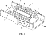
- the plug portion is adapted to be received within a fiber optic adapter 42 of the type shown at FIGURE 4 .
- the fiber optic adapter 42 includes first and second receptacles 44, 46 adapted to receive two fiber optic connectors desired to be optically coupled together.
- the fiber optic adapter 42 includes an alignment sleeve 48 for receiving and coaxially aligning the ferrules of the two fiber optic connectors desired to be coupled together.
- the fiber optic adapter 42 also includes latches 50 corresponding to each of the receptacles 46, 48. The latches 50 are adapted to mechanically retain the fiber optic connectors within the receptacles 46, 48.
- the connector body 22 includes exterior shoulders 52 on opposite sides of the connector body 22.
- the ferrule 38 fits within the alignment sleeve 48 of the fiber optic adapter 42 and the latches 50 snap past and latch against the exterior shoulders 52 to prevent the connector body 22 from being removed from the first receptacle 44.
- the release sleeve 26 mounts over the connector body 22 and is provided for disengaging the latches 50 from the exterior shoulders 52 when it is desired to remove the fiber optic connector 20 from the first receptacle 44.
- the release sleeve 26 includes ramp surfaces 54 configured to engage the latches 50.
- the ramp surfaces 54 of the release sleeve 26 are caused to engage the latches 50 and to push the latches 50 outwardly away from the exterior shoulders 52 of the connector body 22. Pushing the latches 50 away from the exterior shoulders 52 effectively releases the fiber optic connector 20 from the latches 50, thereby allowing the fiber optic connector 20 to be withdrawn from the first receptacle 44.
- the release sleeve 26 includes a distal portion 56 configured to fit within the first receptacle 44 of the fiber optic adapter 42.
- the ramp surfaces 54 are provided at opposite sides of the distal portion 56.
- a distal key 58 fits within a corresponding slot provided at the first receptacle 44.
- the release sleeve 26 also includes a proximal portion 60 that extends proximally away from the distal portion 56.
- the proximal portion 60 forms an elongated handle that extends proximally beyond the proximal end 30 of the connector body 22.
- the proximal portion 60 is generally cylindrical and includes a smaller diameter portion 62 separated from a larger diameter portion 64 by a radial step 66.
- the larger diameter portion 64 includes a proximal gripping portion 68.
- the release sleeve 26 also includes a proximal key 70 that is axially aligned with the distal key 58 and that extends in a distal direction from the radial step 66.
- the fiber optic connector 20 is configured to be inserted within a port 80 defined by a structure 82 such as a terminal, a closure, an enclosure, a panel, a housing or other telecommunications component.
- the structure 82 is an environmentally sealed closure.
- a fiber optic adapter such as the fiber optic adapter 42 can be mounted at an interior end 84 of the port 80 and can be configured for receiving the plug end of the fiber optic connector 20 when the fiber optic connector 20 is inserted within the port 80.
- FIGURES 5 and 6 show the fiber optic connector 20 fully inserted within the port 80.
- the port 80 includes an exterior notch 86 at an exterior end 88 of the port 80.
- the exterior notch 86 is adapted for receiving the proximal key 70 when the fiber optic connector 20 is fully inserted within the port 80. In this way, the notch 86 and the key 70 ensure that the fiber optic connector 20 is inserted into the port 80 at the appropriate rotational orientation.
- the fiber optic connector 20 includes a sealing arrangement for preventing the intrusion of moisture or other material into the structure 82 when the fiber optic connector 20 is inserted within the port 80.
- the sealing arrangement includes an outer circumferential seal 88 (e.g., an O-ring seal) mounted in a circumferential groove defined within the exterior surface of the smaller diameter portion 62 of the proximal portion 60 of the release sleeve 26.
- the port 80 and the smaller diameter portion 62 are both generally cylindrical in shape so as to facilitate providing an effective seal with an O-ring type seal.
- the sealing arrangement also includes a seal 90 between the release sleeve 26 and the connector body 22.
- the seal 90 is defined between an inner surface of the release sleeve 26 and an outer surface of the connector body 22.
- the seal 90 is an O-ring seal shown mounted within a circumferential groove defined within a cylindrical portion of the connector body 22 located adjacent to the proximal end 30 of the connector body 22.
- the seal 90 engages an inner surface of the smaller diameter portion 62 of the release sleeve 26.
- the outer portion of the connector body 22 and the inner surface of the release sleeve 26 are generally cylindrical adjacent the seal 90 so as to enhance effective sealing with an O-ring type seal.
- the fiber optic connector 20 is inserted into the port 80 such that the distal end of the fiber optic connector is received within the first receptacle 44 of a fiber optic adapter secured at the interior end 84 of the port 80.
- the latches 50 of the fiber optic adapter 40 engage the exterior shoulders 52 to secure the optic connector 20 within the port 80.
- the release sleeve 26 is grasped at the larger diameter portion 64 and pulled in a proximal direction. As the release sleeve 26 is pulled in a proximal direction relative to the connector body 22, the ramp surfaces 54 push the latches 50 out of engagement with the exterior shoulders 52 thereby allowing the fiber optic connector 20 to be withdrawn from the port 80.
- FIGURES 7 and 8 show another fiber optic connector 120 in accordance with the principles of the present disclosure. Similar to the previous example, the fiber optic connector 120 is adapted to be received within a fiber optic adapter 42 secured at the interior end of a port 180 defined by a structure of the type previously described.
- the fiber optic connector 120 includes a connector body 122 having a distal end 124 and a proximal end 126. The distal end 124 forms a plug end of the fiber optic connector 120.
- a ferrule 129 supporting an optical fiber of a fiber optic cable is accessible at the plug end of the fiber optic connector 120.
- Ramped notches 128 are provided at opposite sides of the connector body 122 adjacent the distal end 124.
- the latches 50 snap within the notches 128 to provide for light retention of the fiber optic connector 120 within the port 180.
- the configuration of the ramped notches 128 allows the connector body 122 to be pulled from the latches 50 without the need of a release sleeve.
- the connector body 122 includes a plug portion 130 at the distal end 124.
- the ramped notches 128 are provided at opposite sides of the plug portion 130 and the ferrule is accessible at the distal-most end of the plug portion 130.
- the connector body 122 also includes an intermediate section 132 positioned at a proximal end of the plug portion 130.
- a radial shoulder 133 is defined between the plug portion 130 and the intermediate portion 132.
- the intermediate portion 132 is generally cylindrical in shape and defines a circumferential groove in which a sealing member, such as an O-ring 135, is mounted.
- the connector body 122 also includes a proximal portion 134 positioned adjacent to the proximal end 126.
- the proximal portion 134 has a generally rectangular transverse cross-sectional shape.
- the connector body 122 also includes a resilient latch 136 having a base end 138 integrally formed with the proximal portion 134.
- the fiber optic connector 120 further includes an inner hub 144 that supports a spring 146 used to bias the ferrule in a distal direction.
- the hub 144 mounts within the connector body 122.
- a rear extension 148 can attach to the hub 144 and extend proximally from the proximal end 126 of the connector body 122.
- a boot or heat shrink 150 can be mounted at the proximal end of the rear extension 148.
- a fiber optic cable can be connected to the fiber optic connector 120 with a fiber of the fiber optic cable being supported at the ferrule.
- the heat shrink or boot 150 can be used to provide strain relief at the interface between the cable and the fiber optic connector 120 and can also provide sealing about the rear extension 148.
- a seal can also be provided between the exterior of the rear extension 148 and the interior of the connector body 122.
- the fiber optic connector 120 can be inserted into the port such that the plug portion 130 is received within the receptacle 44 of the fiber optic adapter 42. As so positioned, the latches 50 of the fiber optic adapter 42 fit within the ramped notches 128. Additionally, the latch 136 snaps within a catch 152 defined by the port 180.
- the port 180 includes a generally rectangular portion 156 that receives the intermediate portion 132 of the connector body 122 and a cylindrical portion 158 that receives the proximal portion 134 of the connector body 122.
- the intermediate portion 132 can define a circumferential groove in which an O-ring seal 139 is positioned.
- the O-ring seal 139 can provide a seal between the connector body 122 and the cylindrical portion of the port 180.
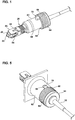
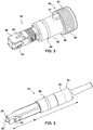
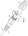
- FIGURES 9-11 show a connector arrangement 220 in accordance with the principles of the present disclosure.
- the connector arrangement 220 includes a fiber optic connector 222, a port 224 defined within a closure 226 or other structure, a fiber optic adapter 42 mounted at the port 224 and configured for receiving the fiber optic connector 222, and a protective shell 228 that mounts over the port 224 and encloses the fiber optic connector 224.
- the fiber optic connector 222 is depicted as an SC-type fiber optic connector.
- the fiber optic connector 222 includes a connector body 230 having shoulders 232 for engaging the latches 50 of the fiber optic adapter 42.
- the fiber optic connector 222 mounts at the end of a fiber optic cable 235.
- a flexible strain-relief boot 234 provides strain relief at the interface between the fiber optic cable 235 and the connector body 230.
- An optical fiber of the fiber optic cable 235 is supported within a ferrule 236 accessible at the distal end of the fiber optic connector 222.
- a release sleeve 238 mounts over the connector body 230. The release sleeve 238 is axially moved relative to the connector body and includes ramp structures for disengaging the latches 50 from the shoulders of the connector body 230 when it is desired to remove the fiber optic connector 222 from the fiber optic adapter 42.
- the port 224 includes an opening 250 in which the fiber optic adapter 42 is mounted.
- the port 224 also includes an exterior sleeve 252 that is generally cylindrical and that surrounds the outer receptacle of the adapter 42.
- the sleeve 252 includes external threads 254.
- the protective shell 228 is configured for ruggedizing, protecting, and sealing the connector-to-adapter interface at the port 224.
- the protective shell includes a distal end 260 and a proximal end 262.
- the protective shell 228 also includes an interior cavity 264 sized to receive the fiber optic connector 220 therein.
- the distal end 260 is open and substantially cylindrical.
- the protective shell 228 can have a relatively rigid construction made of a hard, plastic material such as polymide or other materials.
- the distal end 260 can include internal threads that mate with the exterior threads 254 of the sleeve 252.
- a seal e.g., an O-ring seal
- the proximal end 262 can support a sealing plug 270 that provides a seal between the jacket of the fiber optic cable 235 and the protective shell 228.
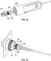
- the connector arrangement 320 has the same general configuration as the connector arrangement 220 except the connector arrangement 320 has a modified release sleeve 352 with a proximal flange 353 and also has a modified protective shell 328 having an internal retention member 329 ( FIGURE 14 ).
- the protective shell 328 is threaded onto the sleeve 352
- the retention member 329 abuts against the end flange 353 of the release sleeve 352 to provide additional retention force for retaining the fiber optic connector 322 within the port 224.
- FIGURES 15-17 show still another connector arrangement 420 in accordance with the principles of the present disclosure.
- the connector arrangement 420 has the same basic configuration as the connector arrangement 220 except the protective shell 228 has been replaced with a protective boot 428.
- the protective boot 428 can have a flexible, bendable construction similar to a standard boot on a fiber optic connector.
- the protective boot 428 includes an internal cavity configured for receiving the fiber optic connector 222.
- a distal end of the protective boot 428 connects to a port structure 424 via a snap-fit connection.
- a proximal end of the protective boot 428 can have a segmented, tapered configuration that reduces in cross-sectional shape as the tapered structure extends in a proximal direction.
- the boot of the fiber optic connector can fit at least partially within the tapered portion of the protective boot 428.
- FIGURES 18-23 and 28 illustrate convertible connector arrangements that enable different ruggedization features to be added to a core connector assembly to fit with the particular interface provided at a given port.
- a connector body 530, 830 is mounted to a sealing and cable attachment unit 570, 570A, 876, which can also be referred to as a universal connector mount.
- the connector body 530, 830 and sealing and cable attachment unit 570, 570A, 876 together form the core connector assembly.
- various shrouds 528, 860 and port fasteners 553, 870 can be added to the core connector assembly to enable the core connector assembly to fit at various ports 524, 824.
- various fasteners 602, 884 couple the shrouds 528, 860 to the sealing and cable attachment units 570, 876.
- the shroud 528 fastens directly to the sealing and cable attachment unit 570A (e.g., by a snap-fit connection).
- the ferrule assembly 531 includes a ferrule 533 mounted to a hub 535.
- the ferrule 533 includes a central passage 537 for receiving an optical fiber.
- the ferrule assembly 531 further includes a spring 532 for biasing the hub 535 and the ferrule 533 in a forward direction relative to the connector body 530.
- a front of the fiber guide 534 forms a spring stop against which one end the spring 532 seats.
- the other end of the spring 532 abuts against a flange on the hub 535 to bias the hub 535 forward relative to the fiber guide 534.
- the hub 535 is held between the spring 532 and the connector body 530.
- the connector body 530, 830 includes a front end 539 and a rear end 541.
- the ferrule assembly 531 mounts within the connector body 530 adjacent the front end 539. As so mounted, the ferrule 533 is accessible at the front end 539 of the connector body 530.
- the front end 539 of the connector body 530, 830 forms a plug configured to be received within a corresponding fiber optic adapter 542.
- the sealing and cable attachment unit 570, 570A, 876 extends through the rear end 541 of the connector body 530, 830 and engages the fiber guide 534.
- the connector body 530, 830 can have a form factor consistent with an SC-connector. However, other types of connector bodies can be utilized.
- the fiber optic connectors 530, 830 can have modified shoulders that are angled or tapered so as to be removable from the fiber optic adapter 842 without the use of a release sleeve.
- the fiber optic connector 828 does not have a release sleeve.
- FIGURES 18-20 show a connector arrangement 520 in accordance with the principles of the present disclosure.
- the connector arrangement 520 includes a fiber optic connector 522 having a connector body 530 and a sealing and cable attachment unit 570.
- the fiber optic adapter 542 can include an alignment sleeve 543 configured for receiving the ferrule 533.
- the fiber optic adapter 542 can be mounted at a port 524 within a closure 526 or other structure.
- the fiber optic adapter 542 does not have latches at the port 524 for engaging the connector body 530.
- the connector arrangement 520 does not include a release sleeve that mounts over the connector body 530.
- the connector arrangement 520 further includes an example protective shroud or shell 528 that mounts over the connector body 530.
- the protective shell 528 mounts to the sealing and cable attachment unit 570 of the connector 522.
- the protective shell 528 can include a front end 545 and a rear end 547.
- the front end 545 can include a key or keying arrangement for providing rotational alignment between the protective shell 528 and the port 524.
- an environmental seal can be provided between the protective shell 528 and the closure 526 to provide sealing of the port 524.
- sealing can be provided in a variety of ways, in the depicted example, sealing can be provided by a seal 549 (e.g., an O-ring seal) that mounts about an exterior of the protective shell 528 near the front end 545.
- the seal 549 is a radial seal mounted within a circumferential groove 551 defined at the exterior of the protective shell 528.
- the seal 549 is radially compressed between the exterior surface of the protective shell 528 and a circumferential sealing surface defined by the closure 526 at the port 524.
- axial seals, face seals, or other types of seals can be used.
- the protective shell 528 can fit over a sleeve provided at the port 524 and sealing can be provided between the interior of the protective shell and the exterior of the sleeve.
- a retaining element or fastener can be used to secure the protective shell 528 within the port 524.
- the retaining element can include fastening structures such as threads or bayonet members that interlock with the corresponding fastening structures provided at the port 524.
- a retaining structure in the form of a fastening nut 553 is used to retain the protective shell 528 within the port 524.
- the fastening nut 553 includes external threads 555 that mate with corresponding internal threads 557 of the port 524 to retain the protective shell 528 within the port 524.
- the fastening nut 553 includes an engagement portion 559 (e.g., a front end) that engages a corresponding engagement portion 561 (i.e., a shoulder) of the protective shell 528 so as to retain the protective shell 528 within the port 524 (see FIGURE 20 ).
- the fastening nut 553 is positioned over the protective shell 528 and is free to rotate about a central axis of the protective shell 528 and is also free to move axially relative to the protective shell 528.
- the connector assembly 520 further includes a sealing and cable attachment unit 570 positioned at the rear end 547 of the connector body 530.
- the sealing and cable attachment unit 570 attaches at the rear end 541 of the connector body 530.
- the sealing end cable attachment unit 570 can attach to the rear end 541 of the connector body 530 by a mechanical interface such as a snap-fit connection, a threaded connection, a bayonet type connection or other type of connection.
- the sealing end cable attachment unit 570 is secured to the connector body 530 by a snap-fit connection.
- the sealing and cable attachment unit 570 is coupled to the connector body 530 by inserting the sealing and cable attachment unit 570 through the rear end 547 of the shell 528 and attaching the sealing and cable attachment unit 570 to the rear end 541 of the connector body 530.
- a fiber optic cable 580 can be secured to the sealing and cable attachment unit 570.
- An optical fiber 582 of the fiber optic cable can extend through the sealing and cable attachment unit 570 through the connector body 530 to the ferrule 533.
- adhesive can be used to secure the optical fiber 582 within the ferrule 533.
- the fiber optic cable 580 can also include an outer jacket 584 and a strength element (e.g., a reinforcing component such as Aramid yarn, fiber reinforce epoxy rods, fiberglass strands, etc.).
- the jacket 584 and the reinforcing structure can be secured to the sealing and cable attachment unit 570.
- the jacket and/or the reinforcing structure can be crimped, mechanically bonded or otherwise attached to the sealing and cable attachment unit 570.
- a structure such as a heat shrink sleeve can be used to provide sealing between the jacket 584 and the sealing and cable attachment unit 570.
- the sealing and cable attachment unit 570 includes a rear body 590 defining a central passage 592 for receiving the optical fiber 582.
- the rear body 590, protective shell 528 and the connector body 530 can all have a relatively rigid construction made of a hard, plastic material such as polymide or other materials.
- the rear body 590 includes attachment structure for securing the sealing and cable attachment unit 570 to the rear end 541 of the connector body 530.
- the rear body 590 includes snap-fit tabs 594 that fit within corresponding openings 595 defined by the connector body 530.
- environmental sealing is provided between the rear body 590 and the protective shell 528.
- the rear body 590 can fit within the protective shell 528 and a seal can be provided therein between.
- the seal can include a radial seal that provides sealing between an exterior circumferential surface of the rear body 590 and an interior circumferential surface of the protective shell 528.
- an axial seal may be used to provide sealing against an axial end of the protective shell 528.
- the sealing and cable attachment unit 570 includes a radial seal 596 (e.g., an O-ring seal) that is radially compressed between an exterior surface of the rear body 590 and an interior surface of the protective shell 528.
- the seal 596 mounts within a circumferential groove 598 defined about the periphery of the rear body 590.
- the sealing and cable attachment unit 570 further includes a rear pocket 599 for receiving the jacket 584 of the fiber optic cable 580.
- the rear pocket 599 is defined by a rear extension 600 of the rear body 590.
- a heat shrink sleeve can be applied over the rear extension and over the jacket so as to provide sealing between the rear body 590 and the exterior of the cable jacket 584.
- the connector arrangement 520 can include a fastener 602 that connects the shroud 528 to the sealing and cable attachment unit 570.
- the fastener 602 in the form of an internally threaded sleeve 602 having internal threads that mate with corresponding external threads provided at the rear end 547 of the protective shell 528.
- the fastener 602 is structured for enhancing sealing of the sealing and cable attachment unit 570 within the protective shell 528.
- the fastener 602 can act as a radial compression element. When mounted at the rear end 547 of the protective shell 528, the fastener 602 can radially compress the protective shell 528.
- the seal 596 is radially compressed and friction between the protective shell 528 and the sealing and cable attachment unit 570 is enhanced so as to resist the sealing and cable attachment unit 570 from being withdrawn rearwardly from the protective shell 528.
- the fastener 602 and the protective shell 528 can have mating tapers that generate or enhance radial compression of the protective shell 528 as the fastener is threaded on the rear end of the protective shell 528.
- the connector arrangement 520 further includes a strain relief boot 604 that mounts to the rear end 547 of the protective shell 528 and that coincides with a portion of the fiber optic cable 580.
- the strain relief boot 604 can have a flexible configuration and can be configured to provide strain relief and bend radius protection to the fiber optic cable 580 at the interface between the fiber optic cable and the connector arrangement 520.
- one or more seals for sealing the port 524 can be provided between the fastening element and the closure 526.
- the connector arrangement 520 can also include a dust cap 606 that mounts over the front end 539 of the fiber optic connector 522 and over the front end 545 of the protective shell 528 when the connector arrangement 520 is not in use.
- the dust cap 606 can include internal threads 608 that mate with the threads of the fastening element. When it is desired to use the connector arrangement 520, the dust cap is removed thereby allowing the connector arrangement 520 to be inserted into the port 524.
- the connector arrangement 520 is inserted into the port 524, the front end 539 of the fiber optic connector 522 is received within the fiber optic adapter 542 and the ferrule 533 is received within the alignment sleeve 543 of the fiber optic adapter 542.
- the front end 545 of the protective sleeve 528 fits within the port 524 and can be rotationally aligned by intermating keying structures such as projections, tabs, paddles, etc.
- the seal 549 forms a seal between the exterior of the protective shell 528 and the portion of the closure 526 defining the port 524.
- the fastening nut 553 can be slid forwardly along the protective shell 528 until the external threads 555 engage the internal threads 557 of the port 524. The fastening nut 553 is then threaded into the port 524. Engagement between the engagement portions 559, 561 retains the connector arrangement 520 within the port 524.
- FIGURES 21-23 illustrate another connector arrangement 520A in accordance with the principles of the present disclosure.
- the connector arrangement 520A has the same basic arrangement as the connector arrangement 520 of FIGURES 18-20 , except a modified sealing and cable attachment unit 570A is provided.
- the sealing and cable attachment unit 570A has the same basic construction as the sealing and cable attachment unit 570, except the sealing and cable attachment unit 570A is configured to interconnect with the rear end of the protective shell 528 by a snap-fit connection.
- snap-fit tabs are snapped within corresponding openings defined by the protective shell 528 such that the sealing and cable attachment unit 570A is effectively attached to the protective shell 528.
- a front portion of the sealing and cable attachment unit 570A is inserted through the rear end 547 of the shell 528 and an intermediate portion of the sealing and cable attachment unit 570A attaches to the rear end 547 of the shell 528.
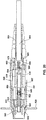
- FIGURE 24 illustrates another fiber optic connection system 720 in accordance with the principles of the present disclosure.
- the fiber optic connection system 720 includes a closure 726 (e.g., a housing, enclosure, box, etc.) defining a port 724.
- the fiber optic connection system 720 also includes a first fiber optic cable 725 positioned inside the closure 726 and a second fiber optic cable 727 positioned outside the closure 726.
- first fiber optic cable 725 is less robust than the second fiber optic cable 727.
- the first and second fiber optic cables 725, 727 have connectorized ends that are optically connected at the port 724.
- a receptacle 750 forming an adapter mount is connected (integrally or mechanically connected) to an inner surface of the closure 726 in general alignment with the port 724.
- a fiber optic adapter 742 is mounted within the receptacle 750. While a variety of different styles of fiber optic adapters can be used, one example, the fiber optic adapter 742 is an SC-type fiber optic adapter adapted for receiving an SC-type fiber optic connector.
- the fiber optic adapter 742 includes first and second opposite receptacles 741, 743.
- the fiber optic adapter 742 also includes an alignment sleeve 745.
- the first fiber optic cable 725 is terminated by a fiber optic connector 760 that is received in the first receptacle 741 and the second fiber optic cable 727 is terminated by a fiber optic connector 762 that is received within the receptacle 743.
- ferrules of the fiber optic connectors 760, 762 are coaxially aligned such that an optical connection is made between the optical fibers of the first and second optical cables 725, 727.
- fiber optic connectors 760, 762 are SC-type connectors configured to latch within the first and second receptacles 741, 743.
- the fiber optic connectors 760, 762 include release sleeves that can be retracted to unlatch the fiber optic connectors 760, 762 from their respective receptacles 741, 743.
- the fiber optic connection system 720 further includes a protective shell 728 that is secured to the closure 726 at the port 724 and that protects the fiber optic connector 762.
- protective shell 728 can have a fastening element for fastening the protective shell 728 to the closure 726 at the port 724.
- Sample fastening structures can include mating threads provided at the port 724 and the protective shell 728, mating bayonet connection elements provided between the protective shell 728 and the closure 726, snap-fit connections between the protective shell 728 and the closure 726, or other structures.
- the protective shell includes a front end 763 having external threads 765 that mate with corresponding internal threads 767 defined within the port 724 (e.g., within the receptacle 750).
- environmental sealing is also provided between the closure 726 and the protective shell 728 at the port 724.
- a seal 767 e.g., an O-ring seal
- the seal 767 is a face seal that is axially compressed between a flange 769 of the protective shell 728 and a sealing surface 771 of the closure 726 when the protective shell 728 is secured at the port 724.
- the protective shell 728 further includes a main body 773 and a rear extension 775.
- the rear extension 775 has a smaller diameter than the main body 773 and projects rearwardly from the main body 773.
- the rear extension 775 defines a rear end 777 of the protective shell 728.
- the second fiber optic cable 727 extends through the rear end 777 of the protective shell 728 and extends through the main body 773 to the fiber optic connector 762 received within the fiber optic adapter 742.
- a seal 778 is used to provide a circumferential seal about the jacket of the fiber optic cable 727 and to provide sealing at the rear end 777 of the protective shell 728.
- the seal 778 can include an O-ring seal that extends around the outer diameter of the fiber optic cable 727.
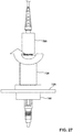
- the fiber optic connection system 720 further includes a seal pressurization/deformation member 780.
- seal pressurization/deformation member 780 that is connected to the rear extension 775 and used to axially compress the seal 778 such that the seal radially deforms about the fiber optic cable 727 and effectively seals the opening defined through the rear extension 775.
- the seal pressurization member 780 is threaded on the rear extension 775.
- the fiber optic connection system 720 further includes a boot 782 carried with the seal pressurization member 780 for providing strain relief and bend radius protection to the fiber optic cable 727 adjacent the rear end of the fiber optic connection system 720.
- the protective shell 728 is movable along the fiber optic cable 727 to provide access to the fiber optic connector 762.
- the seal pressurization member 780 is initially loosened to decompress the seal 778.
- the protective shell 728 is decoupled (e.g., unthreaded) from the port 724 and retracted rearwardly from the port 724 by sliding the protective shell 728 along the fiber optic cable 727 (see FIGURE 25 ).
- the release sleeve of the fiber optic connector 762 can be manually grasped and retracted so as to disengage the fiber optic connector 762 from its corresponding receptacle 743 in the fiber optic adapter 742.
- the fiber optic connector 762 is initially inserted within the receptacle 743 of the fiber optic adapter 742.
- the protective shell 728 is slid over the fiber optic connector 762 and threaded into the port 720 as shown at FIGURE 26 .
- the seal 767 is compressed to provide effective sealing around the port 724 and the front end 763 of the protective shell 728.
- FIGURE 27 shows the seal pressurization member 780 in a sealing position.
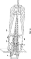
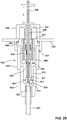
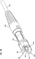
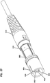
- FIGURES 28-31 show another fiber optic connection system 820 in accordance with the principles of the present disclosure.
- the fiber optic connection system 820 includes a closure 822 defining a port 824.
- the fiber optic connection system 820 further includes a first fiber optic cable 825 terminated by a first fiber optic connector 826 and a second fiber optic cable 827 terminated by a second fiber optic connector 828.
- the fiber optic connection system 820 further includes a fiber optic adapter 842 for optically coupling the first and second fiber optic connectors 826, 827 together such that an optical transmission path is defined between the first and second fiber optic cables 825, 827.
- the fiber optic connectors 826, 828 can have a form factor consistent with an SC-connector.
- the fiber optic connectors 826, 828 can have modified shoulders that are angled or tapered so as to be removable from the fiber optic adapter 842 without the use of a release sleeve.
- the fiber optic connector 828 does not have a release sleeve.
- the fiber optic connection system 820 includes a receptacle 850 through which the fiber optic cable 825 extends.
- a spring 851 or other biasing structure is provided within the receptacle 850. When the fiber optic connection system 820 is assembled and connected together, the spring 851 engages the fiber optic connector 826 to provide resilience support that allows the fiber optic connector to float within the receptacle 850.
- the outer port of the fiber optic adapter 842 may be configured to not include any latches thereby eliminating the need for a release sleeve on the second fiber optic connector 828.
- the fiber optic connection system 820 further includes a protective outer shell or shroud 860 having a front end 862 and an opposite rear end 864.
- the shroud 860 extends over the connector body 830.
- a sealing element 866 is positioned about the protective shell 860 adjacent the front end 862.
- the sealing element 866 can butt against a radial shoulder 868 that projects outwardly from a main body of the protective outer shell 860.
- the fiber optic connection system 820 further includes a port fastener 870 for securing the protective outer shell 860 within the port 824.
- the port fastener 870 is a retention nut having external threads that mate with corresponding internal threads defined within the port 824. As shown at FIGURE 28 , the port fastener 870 can abut against the radial shoulder 868 to effectively retain the protective outer shell 860 within the port 824.
- the port fastener 870 can include other types of retention structures such as snap-fit structures, ratchet structures, bayonet-type fittings or other types of structures for effectively securing the port fastener 870 to the closure 822. It will be appreciated that the port fastener 870 can be rotated relative to the protective outer shell 860 so as to allow the port fastener 870 to be threaded into the port 824 without rotating the protective outer shell 860.
- the protective outer shell 860 includes a main body and a rear extension 872.
- a sealing element 874 is provided adjacent the rear extension for sealing the rear end 864 of the protective outer shell 860.
- the sealing element 874 is mounted about sealing and cable attachment unit 876 having a forward end 877 that fits within the rear extension 872 of the shroud 860.
- the sealing element 874 is captured between the rear end 864 of the protective outer shroud 860 and a radial flange 878 of the sealing and cable attachment unit 876.
- the sealing and cable attachment unit 876 also includes a rear pocket 880 in which a jacket of the second fiber optic cable 827 can be secured.
- a cable seal such as a shape-memory (e.g., heat shrink) sealing sleeve, can be secured over the jacket and over the rear of the rear insert so as to effectively seal the fiber optic cable 827 relative to the sealing and cable attachment unit 876.
- a shape-memory (e.g., heat shrink) sealing sleeve can be secured over the jacket and over the rear of the rear insert so as to effectively seal the fiber optic cable 827 relative to the sealing and cable attachment unit 876.
- the fiber optic connection system 820 further includes a seal compression element 884 that attaches to the rear extension 872 of the protective outer shroud 860 and that functions to axially compress the sealing element 874.
- fastening elements such as threads can be provided between the seal compression element 884 and the rear extension 872.
- the first fiber optic connector 826 can be extended and retracted relative to the port 824.
- the first fiber optic cable 825 can include a stop positioned a length L from the fiber optic connector 826. This allows the connector to be pulled the predetermined length L from the port 824 to provide access for cleaning or making connections.
- FIGURE 29 shows the fiber optic connector 826 in the extended position
- FIGURE 28 shows the fiber optic connector in the retracted position. In the retracted position of FIGURE 28 , the fiber optic connector 826 seats against the spring 851.
- FIGURE 29 shows the port 824 prior to making a connection between the first and second fiber optic cables 825, 827.
- the port 824 is closed and sealed by a dust cap 890 that is threaded into the port 824 and that includes a port seal 892.
- the fiber optic adapter 842 is absent from the port 824.
- the dust cap 890 is removed and the fiber optic adapter 842 is installed on the first fiber optic connector 826.
- the second fiber optic connector 828 is inserted into the fiber optic adapter 842 such that an optical connection is made between the first and second fiber optic cables 825, 827.
- the connector assembly is retracted back into the port 824 until the first fiber optic connector 826 abuts against the spring 851.
- the protective outer shell 860 is inserted over the connector assembly and inserted into the port 824 until the sealing element 866 is compressed between the radial shoulder 868 and a corresponding sealing surface of the port 824.
- the attachment element 870 is then threaded into the port 824, thereby locking the protective outer shell 860 within the port 824 and compressing the sealing element 866.
- the seal compression element 884 is threaded onto the rear extension 872 over the protective outer shell 860 to effectively compress the sealing element 874.
- the second fiber optic connector 828 moves with the protective outer shell 860 and disengages from the fiber optic adapter 842. Unlike the previous example, the second fiber optic connector 828 does not include a release sleeve that is required to be accessed to disengage the fiber optic connector 828 from the fiber optic adapter 842.
- the fiber optic adapter 842 prior to use of the port 824, the fiber optic adapter 842 is not installed on the fiber optic connector 825. In certain examples, this can assist in differing costs. However, in other examples, the fiber optic adapter 842 can be installed on the first fiber optic connector 825 and stored within the dust cap prior to connection with the second fiber optic cable 827. In still further examples, the fiber optic adapter 842 can be integrated with the second fiber optic connector 828 (e.g., be installed on the second fiber optic connector 828 within the protective outer shell 860). In this example, the fiber optic adapter 842 and the second fiber optic connector 828 are inserted together into the port 824 along with the protective outer shell 860 during the connection process. Insertion continues until the first fiber optic connector 825 snaps into the fiber optic adapter 842 and subsequently abuts against the spring 851.
- the first fiber optic connector 826 can be extended and retracted relative to the port 824 by pulling the first fiber optic cable 825 outwardly from the closure 822 through the port 824, and by pushing the fiber optic cable 825 back into the closure 822 through the port 824.
- a stop can be provided on the first fiber optic cable 825 for limiting the length of the first fiber optic cable 825 that can be extended from the port 824.
- FIGURE 32 shows an alternative embodiment where a stop is provided that prevents the first fiber optic connector 826 from being extended from the port 824 and ensures that the first fiber optic connector 826 remains seated against the spring 851.
- FIGURES 33-37 illustrate a ruggedized, customizable fiber optic connector system 900 in accordance with the principles of the present disclosure.
- the fiber optic connector system 900 includes an elongate connector core 902.
- the fiber optic connector system 900 also includes first and second ruggedized exterior assemblies 904, 906 that can be mounted over the elongate connector core 902 to customize the fiber optic connector system 900. For example, a user may choose whether to mount the first ruggedized exterior assembly 904 or the second ruggedized exterior assembly 906 over the elongate connector core 902.
- the first and second ruggedized exterior assemblies 904, 906 have different configurations from one another.
- the first ruggedized exterior assembly 904 has a configuration that is compatible with a first ruggedized fiber optic adapter 908 while the second ruggedized exterior assembly 906 has a configuration that is compatible with a second ruggedized fiber optic adapter 910.
- the first and second ruggedized fiber optic adapters 908, 910 have different fastening and keying configurations and, therefore, are typically compatible with different styles of fiber optic connectors.
- the fiber optic connector system 900 can be readily customized in the field so as to be compatible with the particular style of fiber optic adapter that may be encountered in the field.
- the elongate connector core 902 functions as a precursor structure that can readily be made compatible with different styles of ruggedized fiber optic adapters by selecting the appropriate ruggedized exterior assembly and mounting the selected ruggedized exterior assembly on the elongate connector core 902.
- the elongate connector core 902 includes a front end 912 and an opposite rear end 914.
- the elongate connector core 902 can include a core housing 916 that extends from the front end 912 to the rear end 914. It will be appreciated that the core housing 916 can include one or more pieces.
- the front end 912 of the elongate connector core 902 defines a plug portion configured to be received within a fiber optic adapter.
- the plug portion can have a form factor that matches an existing conventional connector style such as a form factor corresponding to an SC connector, an LC connector, or other type of fiber optic connector.
- the plug portion can have a form factor consistent with a DLX connector of the type disclosed in U.S. Patent No. 7,467,896 , the disclosure of which is hereby incorporated herein by reference in its entirety.
- the rear end 914 of the elongate connector core 902 defines a cable anchoring location for securing a fiber optic cable 918 to the elongate connector core 902.
- the fiber optic cable 918 can include an outer jacket 920 surrounding an optical fiber 922.
- the fiber optic cable 918 can also include strength members (e.g., tensile strength members such as Aramid yarns, fiber reinforced epoxy rods, etc.) that are secured to the cable anchoring location of the elongate connector core 902.
- the strength members can be secured using conventional techniques such as crimping or adhesive.
- the fiber optic cable 918 can also be sealed relative to the elongate connector core 902.
- a shape-memory sleeve 924 e.g., a heat shrink sleeve
- the shape-memory sleeve 924 can be adhesively bonded to the elongate connector core 902 and the outer surface of the outer jacket 920.
- the shape-memory sleeve 924 can function to mechanically anchor the fiber optic cable 918 to the elongate connector core 902 while also providing a seal between the elongate connector core 902 and the fiber optic cable 918.
- optical access to the optical fiber 922 can be provided at the plug portion defined by the front end 912 of the elongate connector core 902.
- a ferrule 926 can be provided at the front end 912 of the elongate connector core 902.
- the optical fiber 922 can be coupled to the ferrule 926.
- the optical fiber 922 can be directly potted within a central bore of the ferrule 926.
- the optical fiber 922 can be spliced to a stub fiber potted within the bore of the ferrule 926.
- the optical fiber 922 is considered optically coupled to the ferrule 926.
- the ferrule 926 can be spring biased in a forward direction toward the front end 912 of the elongate connector core 902.
- the elongate connector core 902 is tunable.
- tunable it is meant that the rotational orientation of the ferrule 926 about its central longitudinal axis can be adjusted relative to the core housing 916 to position a core offset (i.e., an eccentricity) of the optical fiber within the ferrule 926 at a desired rotational position.
- Examples of tuning are disclosed at U.S. Patent No. 5,212,752 and PCT International Publication No. WO 02/052310 , the disclosures of which are hereby incorporated herein by reference in their entirety. It will be appreciated that tuning of the elongate connector core 902 can take place during assembly of the elongate connector core 902.
- the core offset of the optical fiber within the ferrule 926 can be rotated to a particular rotational orientation relative to a key structure corresponding to the core housing 916.
- the rotational position of the ferrule 926 can be retained relative to the core housing 916 by an interface between a ferrule hub of the ferrule 926 and the core housing 916 or by other types of retention arrangements provided within the core housing 916.
- keyed relationships also exist between the elongate connector core 902 and shrouds of the ruggedized exterior assemblies 904, 906 such that the shrouds can only be mounted to the core 902 in one predetermined rotational orientation.
- the elongate core 902 can include a seal 928 configured for providing an annular seal between the core housing 916 and the first ruggedized exterior assembly 904 or between the core housing 916 and the second ruggedized exterior assembly 906.
- the seal 928 is an O-ring mounted within an annular groove defined by the core housing 916.
- the seal 928 is not configured to engage with a corresponding ruggedized adapter.
- the sole function of the seal 928 is to provide sealing with a ruggedized exterior assembly used to customize the elongate connector core 902 to a particular adapter style.
- the seal 928 is positioned rearward of a longitudinal midpoint 930 of the elongate connector core 902. Such a rearward positioning of the seal 928 prevents the seal 928 from being used to provide an annular seal within the port of a corresponding fiber optic adapter.
- the fiber optic connector system 900 further incudes a fastener that mounts on the elongate connector core 902 and that is suitable for attaching either the first ruggedized connector assembly 904 or the second ruggedized exterior assembly 906 to the elongate connector core 902.
- the fastener can be a threaded member such as a nut, a bayonet-type fitting, a snap-fit structure, or other structure.
- the fastener includes a fastening structure 932 incorporated into a strain-relief boot 934 that mounts at the rear end 914 of the elongate connector core 902.
- the strain-relief boot 934 is configured to provide strain relief to the fiber optic cable 918 at the interface between the rear end 914 of the elongate connector core 902 and the fiber optic cable 918.
- a strain-relief boot 934 can have a resilient, polymeric construction.
- the rear strain-relief boot 934 includes a tapered rear end 935 having an exterior surface that tapers inwardly as the strain-relief boot 934 extends in a rearward direction.
- the tapered rear end 935 can include circumferential slits or slots that function to segment the tapered rear end 935 of the strain-relief boot 934 so as to enhance the flexibility.
- the fastening structure 932 is depicted as internal threads 936 provided within the strain-relief boot 934 adjacent a front end of the strain-relief boot 934.
- the front end of the strain-relief boot 934 can have a construction that is more rigid or more robust than the rear end of the strain-relief boot.
- the fastening structure 932 can be embedded or otherwise integrated into the strain-relief boot 934.
- the fastening structure 932 can be a unitary feature molded or otherwise formed into the strain-relief boot 934.
- the first ruggedized exterior assembly 904 is configured to be mounted over the elongate connector core 902 and includes a first shroud 938 configured to be mounted in sealed relation over the elongate connector core 902.
- a rear end of the first shroud 938 abuts against an annular shoulder 940 of the elongate connector core 902 and the seal 928 provides an annular radial seal circumferentially between the exterior circumference of the elongate connector core 902 and the inner circumference of the first shroud 938.
- the first shroud 938 has a forward end that includes a first keying arrangement 942 for rotationally keying the first shroud 938 relative to the first ruggedized fiber optic adapter 908.
- the first keying arrangement 942 includes a pair of paddles 944 (see FIGURE 35 ) configured to be received within corresponding recesses (not shown) defined within the port of the first ruggedized fiber optic adapter 908.
- the first ruggedized exterior assembly 904 also includes a first ruggedized fastening element 946 (omitted from FIG. 35 ) for securing the first ruggedized exterior assembly 904 to the first ruggedized fiber optic adapter 908.
- the first ruggedized fastening element 946 includes a coupling nut having external threads 948 that mate with corresponding internal threads 950 of the first ruggedized fiber optic adapter 908 to secure the elongate connector core 902 and the first ruggedized exterior assembly 904 within the first ruggedized fiber optic adapter 908.
- the first fiber optic adapter 908 includes an alignment sleeve 952 that receives the ferrule 926. Additionally, the first ruggedized exterior assembly 904 includes an exterior seal 953 that provides a circumferential radial seal between the first shroud 938 and the inner surface of the first ruggedized fiber optic adapter 908. Referring to FIGURE 34 , the rear end of the first shroud 938 includes a fastening feature 954 (e.g., external threads) that couples with the fastening structure 932 to secure the first shroud 938 to the elongate connector core 902.
- a fastening feature 954 e.g., external threads
- the first ruggedized fastening element 946 can have alternative configurations.
- the first ruggedized fastening element can include a sleeve having internal threads that mate with corresponding external threads of a corresponding fiber optic adapter.
- the first ruggedized fastening element 946 is a twist-to-lock fastening element.
- snap-fit or other types of interlocking mechanisms also can be used.
- the fastening structure 932 can be referred to as a shroud retainer.
- the shroud retainer is not configured to engage with a corresponding ruggedized fiber optic adapter.
- the sole function of the shroud retainer is to retain a selected ruggedized exterior assembly to the elongate connector core 902.
- the second ruggedized exterior assembly 906 is configured to be mounted over the elongate connector core 902 and includes a second shroud 960 configured to be mounted in sealed relation over the elongate connector core 902.
- a rear end of the second shroud 960 abuts against the annular shoulder 940 of the elongate connector core 902 and a fastening feature 962 (e.g., external threads) engage with the fastening structure 932 to axially retain the second shroud 960 on the elongate connector core 902.
- the seal 928 forms a radial, circumferential seal between the elongate connector core 902 and an internal surface of the second shroud 960.
- the second shroud 960 has a forward end including a second keying arrangement 964 for rotationally keying the second shroud 960 relative to the second ruggedized fiber optic adapter 910.
- the second keying arrangement 964 can include an open ended slot 966 defined at the forward end of the second shroud 960.
- the open ended slot 966 receives a corresponding projection 968 provided within the second ruggedized fiber optic adapter 910 so as to provide rotational keying of the second shroud 960 and the second ruggedized fiber optic adapter 910.
- the ferrule 926 of the elongate connector core 902 is received within an alignment sleeve 967 of the second ruggedized fiber optic adapter 910 and an exterior seal 970 provided around the second shroud 960 provides a radial, circumferential seal between an outer surface of the second shroud 960 and an inner surface of the second ruggedized fiber optic adapter 910.
- the second ruggedized exterior assembly 906 also includes a second ruggedized fastening element 972 for securing the second ruggedized exterior assembly 906 with the elongate connector core 902 secured thereto to the second ruggedized adapter 910.
- the second ruggedized fastening element 972 includes a sleeve having a bayonet-style connection configuration.
- the sleeve can include internal bayonet pins 973 that fit within corresponding bayonet slots 975 defined in a collar of the second ruggedized fiber optic adapter 910.
- FIGURE 36 shows the bayonet-style sleeve interlocked with the collar of the second ruggedized fiber optic adapter 910.
- the first ruggedized exterior assembly 904 is usable in combination with the elongated connector core 902 to make the fiber optic connector system compatible with the first ruggedized adapter 908 and the second ruggedized exterior assembly 906 is usable in combination with the elongated connector core 902 to make the system compatible with the second ruggedized fiber optic adapter 910.
- the first and second ruggedized exterior assemblies 904, 906 are installed on the elongate connector core 902 by inserting the first or second shrouds 938, 960 in a front-to-rear direction over the front end 912 of the elongate connector core 902 and rearwardly onto the elongate connector core 902.
- first ruggedized fastening element 946 is different from the configuration of the second ruggedized fastening element 972. Additionally, it will be appreciated that the first keying arrangement 942 has a configuration that is different from the second keying arrangement 964.
- the bayonet interface can be reversed such that pins are provided on the collar of the second ruggedized fiber optic adapter 910 while bayonet slots are provided within the bayonet sleeve. Similar to the first ruggedized fastening element 946, it will be appreciated that other configurations can be utilized for the second ruggedized fastening element 972. Additionally, different keying configurations also can be utilized. Thus, it should be appreciated that the keying configurations and the fastening configurations are provided for example only, and other types of configurations can be used as well.
- the elongate connector core 902 is a precursor structure that is not intended to be mounted within a ruggedized fiber optic adapter without the use of a corresponding ruggedized exterior assembly. In other examples, the elongate connector core 902 can be converted to be compatible with a ruggedized fiber optic adapter without requiring the use of an intermediate shroud.
- the plug end of the elongate connector core 902 can be provided with a DLX form factor (e.g., as shown at FIGURE 31 ) and the elongate connector core 902 can be converted to a DLX-type connector by installing a fiber optic adapter seal over the exterior of the elongate connector core 902 adjacent the front end and by installing a ruggedized fastening element directly over the elongate connector core 902 without an intermediate shroud.
- the ruggedized fastening element can be secured to the elongate connector core 902 via the fastening structure 932.
Landscapes
- Physics & Mathematics (AREA)
- General Physics & Mathematics (AREA)
- Optics & Photonics (AREA)
- Mechanical Coupling Of Light Guides (AREA)
Abstract
Description
- This application claims the benefit of
U.S. Provisional Application No. 61/869,672 filed on August 24, 2013 U.S. Provisional Application No. 61/971,967 filed on March 28, 2014 U.S. Provisional Application No. 61/973,677 filed on April 1, 2014 - The present disclosure relates generally to fiber optic connectors. More particularly, the present disclosure relates to fiber optic connectors suitable for outside environmental use.
- Fiber optic communication systems are becoming prevalent in part because service providers want to deliver high bandwidth communication capabilities (e.g., data and voice) to customers. Fiber optic communication systems employ a network of fiber optic cables to transmit large volumes of data and voice signals over relatively long distances. Optical fiber connectors are an important part of most fiber optic communication systems. Fiber optic connectors allow two optical fibers to be quickly optically connected without requiring a splice. Fiber optic connectors can be used to optically interconnect two lengths of optical fiber. Fiber optic connectors can also be used to interconnect lengths of optical fiber to passive and active equipment.
- A typical fiber optic connector includes a ferrule assembly supported at a distal end of a connector housing. A spring is used to bias the ferrule assembly in a distal direction relative to the connector housing. The ferrule functions to support an end portion of at least one optical fiber (in the case of a multi-fiber ferrule, the ends of multiple fibers are supported). The ferrule has a distal end face at which a polished end of the optical fiber is located. When two fiber optic connectors are interconnected, the distal end faces of the ferrules abut one another and the ferrules are forced proximally relative to their respective connector housings against the bias of their respective springs. With the fiber optic connectors connected, their respective optical fibers are coaxially aligned such that the end faces of the optical fibers directly oppose one another. In this way, an optical signal can be transmitted from optical fiber to optical fiber through the aligned end faces of the optical fibers. For many fiber optic connector styles, alignment between two fiber optic connectors is provided through the use of an intermediate fiber optic adapter.
- Ruggedized (i.e., hardened) fiber optic connection systems include fiber optic connectors and fiber optic adapters suitable for outside environmental use. These types of systems are typically environmentally sealed and include robust fastening arrangements suitable for withstanding relatively large pull loading and side loading. Example ruggedized fiber optic connection systems are disclosed by
US. Patent Nos. 7,467,896 ;7,744,288 and8,556,520 . - Certain aspects of the present disclosure relate to a fiber optic connector system that efficiently provides effective compatibility with a number of different types of ruggedized fiber optic adapter configurations. In certain examples, the fiber optic connector system includes an elongate connector core including a front end defining a plug portion and a rear end defining a cable anchoring location. The fiber optic connector system also includes a first ruggedized exterior assembly configured to be mounted over the elongate connector core. The first ruggedized exterior assembly includes a first shroud configured to be mounted in a sealed relation over the elongate connector core. The first shroud has a forward end that includes a first keying arrangement for rotationally keying the first shroud relative to a first ruggedized fiber optic adapter. The first ruggedized exterior assembly also includes a first ruggedized fastening element for securing the first ruggedized exterior assembly to the first ruggedized fiber optic adapter. The fiber optic connector system also includes a second ruggedized exterior assembly configured to be mounted over the elongate connector core. The second ruggedized exterior assembly includes a second shroud configured to be mounted in sealed relation over the elongate connector core. The second shroud has a forward end that includes a second keying arrangement for rotationally keying the shroud relative to a second ruggedized fiber optic adapter. The first keying arrangement has a different keying configuration than the second keying arrangement. The second ruggedized exterior assembly also includes a second ruggedized fastening element for securing the second ruggedized exterior assembly to the second ruggedized fiber optic adapter. The first ruggedized fastening element has a different fastening configuration than the second ruggedized fastening element. The first ruggedized exterior assembly is usable in combination with the elongated connector core to make the fiber optic connector system compatible with the first ruggedized fiber optic adapter and the second ruggedized exterior assembly is usable in combination with the elongated connector core to make the system compatible with the second ruggedized fiber optic adapter. In this way, the elongate connector core can be factory mounted to a cable, and the cable assembly can be shipped in the field without any ruggedized exterior assemblies mounted thereon. In the field, a technician can install either the first ruggedized exterior assembly or the second ruggedized exterior assembly on the elongate connector core depending upon the style of ruggedized fiber optic adapter encountered. In this way, the system effectively provides compatibility with different styles of ruggedized fiber optic adapters. In other examples, the most commonly used style of ruggedized exterior assembly can be factory mounted on the elongate connector core and shipped to the field. In this example, in the event a non-compatible fiber optic adapter is encountered, the pre-installed ruggedized exterior assembly can readily be removed and replaced with a ruggedized exterior assembly that is compatible with the encountered ruggedized fiber optic adapter.
- Aspects of the disclosure are directed to a fiber optic connector including a connector body having a distal end at least partially forming a plug portion of the fiber optic connector; a release sleeve mounted on the connector body and movable relative to the connector body along a lengthwise axis of the connector body; a first seal that extends around an exterior of the release sleeve; and a second seal that extends around an exterior of the connector body and provides sealing between the release sleeve and the connector body.
- Other aspects of the disclosure are directed to a fiber optic connector including a connector body defining a plug portion at a distal end, a proximal portion at the proximal end, and an intermediate portion between the plug portion and the proximal portion; a seal that mounts around the intermediate portion; and a flexible latch integrally formed with the proximal portion.
- Other aspects of the disclosure are directed to a fiber optic connection arrangement including structure defining a port, the structure including an exterior sleeve; a fiber optic adapter mounted at the port; a fiber optic connector configured to be received within a receptacle of the fiber optic adapter; and a protective structure that mounts over the fiber optic connector. The fiber optic connector includes a connector body defining a plug portion and a boot attached the connector body. The protective structure includes a distal end that attaches to the exterior sleeve of the port and a proximal end through which a cable connected to the fiber optic connector is routed.
- Other aspects of the disclosure are directed to a fiber optic connection arrangement including a core connector assembly; a protective outer shell; and a port fastener. The core connector assembly includes a sealing and cable attachment unit and a connector body coupled to the sealing and cable attachment unit. The sealing and cable attachment unit includes a seal. The protective outer shell is configured to couple to the sealing and cable attachment unit of the core connector assembly. The protective outer shell engages the seal when the protective outer shell is coupled to the core connector assembly. The port fastener is configured to couple the protective outer shroud to a port.
- A variety of additional inventive aspects will be set forth in the description that follows. The inventive aspects can relate to individual features and to combinations of features. It is to be understood that both the forgoing general description and the following detailed description are exemplary and explanatory only and are not restrictive of the broad inventive concepts upon which the embodiments disclosed herein are based.
-
-
FIGURE 1 is a perspective view of a fiber optic connector in accordance with the principles of the present disclosure; -
FIGURE 2 is a perspective view of a release sleeve of the fiber optic connector ofFIGURE 1 ; -
FIGURE 3 is a perspective view of a connector body of the fiber optic connector ofFIGURE 1 ; -
FIGURE 4 is a cross-sectional view of a fiber optic adapter configured to receive the fiber optic connector ofFIGURE 1 ; -
FIGURE 5 is a perspective view showing the fiber optic connector ofFIGURE 1 inserted within a port of a closure, panel or other structure; -
FIGURE 6 is a cross-sectional view showing the fiber optic connector ofFIGURE 1 mounted within the port ofFIGURE 5 ; -
FIGURE 7 is a perspective view of another fiber optic connector in accordance with the principles of the present disclosure; -
FIGURE 8 show the fiber optic connector ofFIGURE 7 mounted within a port of a closure, panel or other structure; -
FIGURE 9 is a perspective view of another connector arrangement in accordance with the principles of the present disclosure; -
FIGURE 10 shows the connector arrangement ofFIGURE 9 secured at a port of a closure, panel or other structure; -
FIGURE 11 is a cross-sectional view showing the connector and port arrangement ofFIGURE 10 ; -
FIGURE 12 illustrates a further connector arrangement in accordance with the principles of the present disclosure; -
FIGURE 13 shows the connector arrangement ofFIGURE 12 with a connector of the connector arrangement inserted within a port of a closure, panel or other structure; -
FIGURE 14 is a cross-sectional view of the connector arrangement ofFIGURE 12 secured at the port ofFIGURE 13 ; -
FIGURE 15 illustrates yet another connector arrangement in accordance with the principles of the present disclosure; -
FIGURE 16 shows the connector arrangement ofFIGURE 15 secured at a port of a closure, panel or other structure; -
FIGURE 17 is a cross-sectional view of the port and connector arrangement ofFIGURE 16 ; -
FIGURES 18-20 show anotherconnector arrangement 520 in accordance with the principles of the present disclosure; -
FIGURES 21-23 illustrate anotherconnector arrangement 720 in accordance with the principles of the present disclosure. -
FIGURE 24 illustrates another fiberoptic connection system 720 in accordance with the principles of the present disclosure; -
FIGURES 25-27 illustrate how an example protective shell can be movable along the fiber optic cable to provide access to the fiber optic connector; -
FIGURES 28-31 show another fiber optic connection system in accordance with the principles of the present disclosure; -
FIGURE 32 shows an alternative embodiment where a stop is provided that prevents the first fiber optic connector from being extended from the port and ensures that the first fiber optic connector remains seated against the spring; -
FIGURE 33 illustrates a customizable fiber optic connector system including an elongate connector core in accordance with the principles of the present disclosure; -
FIGURE 34 illustrates the customizable fiber optic connector system ofFIGURE 33 with a first ruggedized exterior assembly secured on the elongate connector core; -
FIGURE 35 shows the connector arrangement ofFIGURE 34 in perspective view with an outer fastening element removed for clarity; -
FIGURE 36 shows the customizable fiber optic connector system ofFIGURE 33 with a second ruggedized exterior assembly secured on the elongate connector core; and -
FIGURE 37 is a perspective view of the connector arrangement ofFIGURE 36 with an outer fastening element removed for clarity. - The expansion of fiber optic networks toward the premises has driven the demand for enhanced fiber optic connectors suitable for outside environmental uses. For example, in a given fiber optic network, outside fiber optic connectors are used to connect fiber optic cables to structures such as drop terminals (i.e., multi-service terminals), optical network terminals (ONTs), breakout locations on fiber optic cables, fiber distribution hubs, splice closures, pedestals, or other structures. Effective use of fiber optic connectors in outside environments requires the fiber optic connectors to be sealed against the environment and to have robust designs that can withstand relatively large temperature variations, large pulling loads, and significant side loading. It is also desirable for such connectors to be relatively easy to insert and remove from a port in a structure of the type described above. The present disclosure describes various connectors having rugged, robust designs that are environmentally sealed and that are relatively easy to install and uninstall in the field.
-
FIGURE 1 shows a fiber optic connector 20 in accordance with the principles of the present disclosure. Generally, the fiber optic connector 20 includes a connector body 22 (seeFIG. 3 ) having a length that extends along alengthwise axis 24. The fiber optic connector 20 also includes a release sleeve 26 (seeFIG. 2 ) that mounts over theconnector body 22 and has a limited range of slidable movement relative to theconnector body 22 along thelengthwise axis 24. - Referring to
FIGURE 3 , theconnector body 22 includes adistal end 28 and aproximal end 30. Aboot 32 is mounted adjacent theproximal end 30 of theconnector body 22. Theboot 32 is adapted to receive and provide strain relief to afiber optic cable 34 to which the fiber optic connector 20 is secured. Thefiber optic cable 34 includes anoptical fiber 36 that is routed through theconnector body 22. An end of theoptical fiber 36 is supported within aferrule 38 accessible at thedistal end 28 of theconnector body 22. Theferrule 38 can be spring biased in a distal direction relative to theconnector body 22 by aspring 40. - As described above, the
distal end 28 of theconnector body 22 defines a plug portion of the fiber optic connector 20. The plug portion is adapted to be received within afiber optic adapter 42 of the type shown atFIGURE 4 . Thefiber optic adapter 42 includes first andsecond receptacles fiber optic adapter 42 includes analignment sleeve 48 for receiving and coaxially aligning the ferrules of the two fiber optic connectors desired to be coupled together. Thefiber optic adapter 42 also includeslatches 50 corresponding to each of thereceptacles latches 50 are adapted to mechanically retain the fiber optic connectors within thereceptacles - Referring back to
FIGURE 3 , theconnector body 22 includesexterior shoulders 52 on opposite sides of theconnector body 22. When the plug portion of theconnector body 22 is inserted within thefirst receptacle 44 of thefiber optic adapter 42, theferrule 38 fits within thealignment sleeve 48 of thefiber optic adapter 42 and thelatches 50 snap past and latch against theexterior shoulders 52 to prevent theconnector body 22 from being removed from thefirst receptacle 44. Therelease sleeve 26 mounts over theconnector body 22 and is provided for disengaging thelatches 50 from theexterior shoulders 52 when it is desired to remove the fiber optic connector 20 from thefirst receptacle 44. For example, as shown atFIGURE 2 , therelease sleeve 26 includes ramp surfaces 54 configured to engage thelatches 50. By pulling therelease sleeve 26 proximally relative to theconnector body 22 when the fiber optic connector 20 is mounted within thefirst receptacle 44, the ramp surfaces 54 of therelease sleeve 26 are caused to engage thelatches 50 and to push thelatches 50 outwardly away from theexterior shoulders 52 of theconnector body 22. Pushing thelatches 50 away from theexterior shoulders 52 effectively releases the fiber optic connector 20 from thelatches 50, thereby allowing the fiber optic connector 20 to be withdrawn from thefirst receptacle 44. - Referring to
FIGURE 2 , therelease sleeve 26 includes adistal portion 56 configured to fit within thefirst receptacle 44 of thefiber optic adapter 42. The ramp surfaces 54 are provided at opposite sides of thedistal portion 56. A distal key 58 fits within a corresponding slot provided at thefirst receptacle 44. Therelease sleeve 26 also includes aproximal portion 60 that extends proximally away from thedistal portion 56. Theproximal portion 60 forms an elongated handle that extends proximally beyond theproximal end 30 of theconnector body 22. In one example, theproximal portion 60 is generally cylindrical and includes asmaller diameter portion 62 separated from alarger diameter portion 64 by aradial step 66. Thelarger diameter portion 64 includes a proximal grippingportion 68. Therelease sleeve 26 also includes a proximal key 70 that is axially aligned with thedistal key 58 and that extends in a distal direction from theradial step 66. - Referring to
FIGURE 5 , the fiber optic connector 20 is configured to be inserted within aport 80 defined by astructure 82 such as a terminal, a closure, an enclosure, a panel, a housing or other telecommunications component. In certain examples, thestructure 82 is an environmentally sealed closure. While not depicted inFIGURES 5 and6 , a fiber optic adapter such as thefiber optic adapter 42 can be mounted at aninterior end 84 of theport 80 and can be configured for receiving the plug end of the fiber optic connector 20 when the fiber optic connector 20 is inserted within theport 80.FIGURES 5 and6 show the fiber optic connector 20 fully inserted within theport 80. Theport 80 includes anexterior notch 86 at anexterior end 88 of theport 80. Theexterior notch 86 is adapted for receiving the proximal key 70 when the fiber optic connector 20 is fully inserted within theport 80. In this way, thenotch 86 and the key 70 ensure that the fiber optic connector 20 is inserted into theport 80 at the appropriate rotational orientation. - Referring to
FIGURE 6 , the fiber optic connector 20 includes a sealing arrangement for preventing the intrusion of moisture or other material into thestructure 82 when the fiber optic connector 20 is inserted within theport 80. In one example, the sealing arrangement includes an outer circumferential seal 88 (e.g., an O-ring seal) mounted in a circumferential groove defined within the exterior surface of thesmaller diameter portion 62 of theproximal portion 60 of therelease sleeve 26. It will be appreciated that theport 80 and thesmaller diameter portion 62 are both generally cylindrical in shape so as to facilitate providing an effective seal with an O-ring type seal. Still referring toFIGURE 6 , the sealing arrangement also includes aseal 90 between therelease sleeve 26 and theconnector body 22. Theseal 90 is defined between an inner surface of therelease sleeve 26 and an outer surface of theconnector body 22. In an example, theseal 90 is an O-ring seal shown mounted within a circumferential groove defined within a cylindrical portion of theconnector body 22 located adjacent to theproximal end 30 of theconnector body 22. Theseal 90 engages an inner surface of thesmaller diameter portion 62 of therelease sleeve 26. The outer portion of theconnector body 22 and the inner surface of therelease sleeve 26 are generally cylindrical adjacent theseal 90 so as to enhance effective sealing with an O-ring type seal. - In use of the fiber optic connector 20, the fiber optic connector 20 is inserted into the
port 80 such that the distal end of the fiber optic connector is received within thefirst receptacle 44 of a fiber optic adapter secured at theinterior end 84 of theport 80. When the fiber optic connector 20 is inserted within theport 80, thelatches 50 of thefiber optic adapter 40 engage theexterior shoulders 52 to secure the optic connector 20 within theport 80. To remove the fiber optic connector 20 from theport 80, therelease sleeve 26 is grasped at thelarger diameter portion 64 and pulled in a proximal direction. As therelease sleeve 26 is pulled in a proximal direction relative to theconnector body 22, the ramp surfaces 54 push thelatches 50 out of engagement with theexterior shoulders 52 thereby allowing the fiber optic connector 20 to be withdrawn from theport 80. -
FIGURES 7 and8 show anotherfiber optic connector 120 in accordance with the principles of the present disclosure. Similar to the previous example, thefiber optic connector 120 is adapted to be received within afiber optic adapter 42 secured at the interior end of aport 180 defined by a structure of the type previously described. Thefiber optic connector 120 includes aconnector body 122 having adistal end 124 and aproximal end 126. Thedistal end 124 forms a plug end of thefiber optic connector 120. Aferrule 129 supporting an optical fiber of a fiber optic cable is accessible at the plug end of thefiber optic connector 120. Rampednotches 128 are provided at opposite sides of theconnector body 122 adjacent thedistal end 124. When the plug end of thefiber optic connector 120 is inserted within thefiber optic adapter 42, thelatches 50 snap within thenotches 128 to provide for light retention of thefiber optic connector 120 within theport 180. The configuration of the rampednotches 128 allows theconnector body 122 to be pulled from thelatches 50 without the need of a release sleeve. - As described above, the
connector body 122 includes aplug portion 130 at thedistal end 124. The rampednotches 128 are provided at opposite sides of theplug portion 130 and the ferrule is accessible at the distal-most end of theplug portion 130. Theconnector body 122 also includes anintermediate section 132 positioned at a proximal end of theplug portion 130. Aradial shoulder 133 is defined between theplug portion 130 and theintermediate portion 132. Theintermediate portion 132 is generally cylindrical in shape and defines a circumferential groove in which a sealing member, such as an O-ring 135, is mounted. Theconnector body 122 also includes aproximal portion 134 positioned adjacent to theproximal end 126. Theproximal portion 134 has a generally rectangular transverse cross-sectional shape. Theconnector body 122 also includes aresilient latch 136 having abase end 138 integrally formed with theproximal portion 134. - Referring to
FIGURE 8 , thefiber optic connector 120 further includes aninner hub 144 that supports aspring 146 used to bias the ferrule in a distal direction. Thehub 144 mounts within theconnector body 122. Arear extension 148 can attach to thehub 144 and extend proximally from theproximal end 126 of theconnector body 122. A boot or heat shrink 150 can be mounted at the proximal end of therear extension 148. As with the previous example, a fiber optic cable can be connected to thefiber optic connector 120 with a fiber of the fiber optic cable being supported at the ferrule. The heat shrink or boot 150 can be used to provide strain relief at the interface between the cable and thefiber optic connector 120 and can also provide sealing about therear extension 148. In certain embodiments, a seal can also be provided between the exterior of therear extension 148 and the interior of theconnector body 122. - Referring again to
FIGURE 8 , thefiber optic connector 120 can be inserted into the port such that theplug portion 130 is received within thereceptacle 44 of thefiber optic adapter 42. As so positioned, thelatches 50 of thefiber optic adapter 42 fit within the rampednotches 128. Additionally, thelatch 136 snaps within acatch 152 defined by theport 180. Theport 180 includes a generallyrectangular portion 156 that receives theintermediate portion 132 of theconnector body 122 and acylindrical portion 158 that receives theproximal portion 134 of theconnector body 122. Theintermediate portion 132 can define a circumferential groove in which an O-ring seal 139 is positioned. The O-ring seal 139 can provide a seal between theconnector body 122 and the cylindrical portion of theport 180. To withdraw thefiber optic connector 120 from theport 180, thelatch 136 is depressed, thereby disengaging thelatch 136 from thecatch 152, thereby allowing thefiber optic connector 120 to be axially pulled from theport 180. -
FIGURES 9-11 show aconnector arrangement 220 in accordance with the principles of the present disclosure. Theconnector arrangement 220 includes afiber optic connector 222, aport 224 defined within aclosure 226 or other structure, afiber optic adapter 42 mounted at theport 224 and configured for receiving thefiber optic connector 222, and aprotective shell 228 that mounts over theport 224 and encloses thefiber optic connector 224. Referring toFIGURE 11 , thefiber optic connector 222 is depicted as an SC-type fiber optic connector. Thefiber optic connector 222 includes aconnector body 230 havingshoulders 232 for engaging thelatches 50 of thefiber optic adapter 42. Thefiber optic connector 222 mounts at the end of afiber optic cable 235. A flexible strain-relief boot 234 provides strain relief at the interface between thefiber optic cable 235 and theconnector body 230. An optical fiber of thefiber optic cable 235 is supported within aferrule 236 accessible at the distal end of thefiber optic connector 222. Arelease sleeve 238 mounts over theconnector body 230. Therelease sleeve 238 is axially moved relative to the connector body and includes ramp structures for disengaging thelatches 50 from the shoulders of theconnector body 230 when it is desired to remove thefiber optic connector 222 from thefiber optic adapter 42. - The
port 224 includes anopening 250 in which thefiber optic adapter 42 is mounted. Theport 224 also includes anexterior sleeve 252 that is generally cylindrical and that surrounds the outer receptacle of theadapter 42. In the depicted embodiment, thesleeve 252 includesexternal threads 254. - The
protective shell 228 is configured for ruggedizing, protecting, and sealing the connector-to-adapter interface at theport 224. The protective shell includes adistal end 260 and aproximal end 262. Theprotective shell 228 also includes aninterior cavity 264 sized to receive thefiber optic connector 220 therein. Thedistal end 260 is open and substantially cylindrical. - In one example, the
protective shell 228 can have a relatively rigid construction made of a hard, plastic material such as polymide or other materials. Thedistal end 260 can include internal threads that mate with theexterior threads 254 of thesleeve 252. A seal (e.g., an O-ring seal) can also be provided at thedistal end 260 adjacent the threads. Theproximal end 262 can support a sealingplug 270 that provides a seal between the jacket of thefiber optic cable 235 and theprotective shell 228. By threading theprotective shell 228 onto thesleeve 252, thefiber optic connector 222 and thefiber optic adapter 42 are effectively protected from the environment. - Referring to
FIGURES 12-14 , afurther connector arrangement 320 is depicted. Theconnector arrangement 320 has the same general configuration as theconnector arrangement 220 except theconnector arrangement 320 has a modifiedrelease sleeve 352 with aproximal flange 353 and also has a modifiedprotective shell 328 having an internal retention member 329 (FIGURE 14 ). When theprotective shell 328 is threaded onto thesleeve 352, theretention member 329 abuts against theend flange 353 of therelease sleeve 352 to provide additional retention force for retaining thefiber optic connector 322 within theport 224. -
FIGURES 15-17 show still anotherconnector arrangement 420 in accordance with the principles of the present disclosure. Theconnector arrangement 420 has the same basic configuration as theconnector arrangement 220 except theprotective shell 228 has been replaced with aprotective boot 428. Theprotective boot 428 can have a flexible, bendable construction similar to a standard boot on a fiber optic connector. Theprotective boot 428 includes an internal cavity configured for receiving thefiber optic connector 222. A distal end of theprotective boot 428 connects to aport structure 424 via a snap-fit connection. A proximal end of theprotective boot 428 can have a segmented, tapered configuration that reduces in cross-sectional shape as the tapered structure extends in a proximal direction. The boot of the fiber optic connector can fit at least partially within the tapered portion of theprotective boot 428. -
FIGURES 18-23 and 28 illustrate convertible connector arrangements that enable different ruggedization features to be added to a core connector assembly to fit with the particular interface provided at a given port. In each of the convertible connector arrangements, aconnector body cable attachment unit connector body cable attachment unit various shrouds port fasteners various ports various fasteners shrouds cable attachment units shroud 528 fastens directly to the sealing andcable attachment unit 570A (e.g., by a snap-fit connection). - As shown in
FIGURE 19 , aferrule assembly 531 and afiber guide 534 are mounted within theconnector body 530. (The corresponding features also are visible inFIGURE 28 .) Theferrule assembly 531 includes aferrule 533 mounted to ahub 535. Theferrule 533 includes acentral passage 537 for receiving an optical fiber. Theferrule assembly 531 further includes aspring 532 for biasing thehub 535 and theferrule 533 in a forward direction relative to theconnector body 530. A front of thefiber guide 534 forms a spring stop against which one end thespring 532 seats. The other end of thespring 532 abuts against a flange on thehub 535 to bias thehub 535 forward relative to thefiber guide 534. Thehub 535 is held between thespring 532 and theconnector body 530. - The
connector body front end 539 and arear end 541. Theferrule assembly 531 mounts within theconnector body 530 adjacent thefront end 539. As so mounted, theferrule 533 is accessible at thefront end 539 of theconnector body 530. Thefront end 539 of theconnector body fiber optic adapter 542. The sealing andcable attachment unit rear end 541 of theconnector body fiber guide 534. In certain examples, theconnector body FIGURE 31 , thefiber optic connectors fiber optic adapter 842 without the use of a release sleeve. Thus, in the depicted example ofFIGURE 31 , thefiber optic connector 828 does not have a release sleeve. -
FIGURES 18-20 show aconnector arrangement 520 in accordance with the principles of the present disclosure. Theconnector arrangement 520 includes afiber optic connector 522 having aconnector body 530 and a sealing andcable attachment unit 570. As shown atFIGURE 20 , thefiber optic adapter 542 can include analignment sleeve 543 configured for receiving theferrule 533. In certain examples, thefiber optic adapter 542 can be mounted at aport 524 within aclosure 526 or other structure. In the depicted example, thefiber optic adapter 542 does not have latches at theport 524 for engaging theconnector body 530. Additionally, theconnector arrangement 520 does not include a release sleeve that mounts over theconnector body 530. - Referring still to
FIGURES 18-20 , theconnector arrangement 520 further includes an example protective shroud or shell 528 that mounts over theconnector body 530. Theprotective shell 528 mounts to the sealing andcable attachment unit 570 of theconnector 522. Theprotective shell 528 can include afront end 545 and arear end 547. Thefront end 545 can include a key or keying arrangement for providing rotational alignment between theprotective shell 528 and theport 524. In certain examples, an environmental seal can be provided between theprotective shell 528 and theclosure 526 to provide sealing of theport 524. While the sealing can be provided in a variety of ways, in the depicted example, sealing can be provided by a seal 549 (e.g., an O-ring seal) that mounts about an exterior of theprotective shell 528 near thefront end 545. In the depicted example, theseal 549 is a radial seal mounted within acircumferential groove 551 defined at the exterior of theprotective shell 528. When theprotective shell 528 is inserted within theport 524 of theclosure 526, theseal 549 is radially compressed between the exterior surface of theprotective shell 528 and a circumferential sealing surface defined by theclosure 526 at theport 524. In other examples, axial seals, face seals, or other types of seals can be used. Moreover, in still other examples, theprotective shell 528 can fit over a sleeve provided at theport 524 and sealing can be provided between the interior of the protective shell and the exterior of the sleeve. - In certain examples, a retaining element or fastener can be used to secure the
protective shell 528 within theport 524. In one example, the retaining element can include fastening structures such as threads or bayonet members that interlock with the corresponding fastening structures provided at theport 524. In the depicted embodiment, a retaining structure in the form of afastening nut 553 is used to retain theprotective shell 528 within theport 524. Thefastening nut 553 includesexternal threads 555 that mate with correspondinginternal threads 557 of theport 524 to retain theprotective shell 528 within theport 524. Thefastening nut 553 includes an engagement portion 559 (e.g., a front end) that engages a corresponding engagement portion 561 (i.e., a shoulder) of theprotective shell 528 so as to retain theprotective shell 528 within the port 524 (seeFIGURE 20 ). Thefastening nut 553 is positioned over theprotective shell 528 and is free to rotate about a central axis of theprotective shell 528 and is also free to move axially relative to theprotective shell 528. - As indicated above, the
fiber optic connector 522 mounts within theprotective shell 528. Theconnector assembly 520 further includes a sealing andcable attachment unit 570 positioned at therear end 547 of theconnector body 530. In one example, the sealing andcable attachment unit 570 attaches at therear end 541 of theconnector body 530. For example, the sealing endcable attachment unit 570 can attach to therear end 541 of theconnector body 530 by a mechanical interface such as a snap-fit connection, a threaded connection, a bayonet type connection or other type of connection. As depicted, the sealing endcable attachment unit 570 is secured to theconnector body 530 by a snap-fit connection. In one example, the sealing andcable attachment unit 570 is coupled to theconnector body 530 by inserting the sealing andcable attachment unit 570 through therear end 547 of theshell 528 and attaching the sealing andcable attachment unit 570 to therear end 541 of theconnector body 530. - In certain examples, a
fiber optic cable 580 can be secured to the sealing andcable attachment unit 570. Anoptical fiber 582 of the fiber optic cable can extend through the sealing andcable attachment unit 570 through theconnector body 530 to theferrule 533. In certain examples, adhesive can be used to secure theoptical fiber 582 within theferrule 533. Thefiber optic cable 580 can also include anouter jacket 584 and a strength element (e.g., a reinforcing component such as Aramid yarn, fiber reinforce epoxy rods, fiberglass strands, etc.). In certain examples, thejacket 584 and the reinforcing structure can be secured to the sealing andcable attachment unit 570. For example, the jacket and/or the reinforcing structure can be crimped, mechanically bonded or otherwise attached to the sealing andcable attachment unit 570. In certain examples, a structure such as a heat shrink sleeve can be used to provide sealing between thejacket 584 and the sealing andcable attachment unit 570. - The sealing and
cable attachment unit 570 includes arear body 590 defining acentral passage 592 for receiving theoptical fiber 582. In certain examples, therear body 590,protective shell 528 and theconnector body 530 can all have a relatively rigid construction made of a hard, plastic material such as polymide or other materials. Therear body 590 includes attachment structure for securing the sealing andcable attachment unit 570 to therear end 541 of theconnector body 530. For example, therear body 590 includes snap-fit tabs 594 that fit within correspondingopenings 595 defined by theconnector body 530. In certain examples, environmental sealing is provided between therear body 590 and theprotective shell 528. For example, therear body 590 can fit within theprotective shell 528 and a seal can be provided therein between. In certain examples, the seal can include a radial seal that provides sealing between an exterior circumferential surface of therear body 590 and an interior circumferential surface of theprotective shell 528. In other examples, an axial seal may be used to provide sealing against an axial end of theprotective shell 528. In the depicted example, the sealing andcable attachment unit 570 includes a radial seal 596 (e.g., an O-ring seal) that is radially compressed between an exterior surface of therear body 590 and an interior surface of theprotective shell 528. In the depicted example, theseal 596 mounts within acircumferential groove 598 defined about the periphery of therear body 590. The sealing andcable attachment unit 570 further includes arear pocket 599 for receiving thejacket 584 of thefiber optic cable 580. Therear pocket 599 is defined by arear extension 600 of therear body 590. In certain examples, a heat shrink sleeve can be applied over the rear extension and over the jacket so as to provide sealing between therear body 590 and the exterior of thecable jacket 584. - In certain examples, the
connector arrangement 520 can include afastener 602 that connects theshroud 528 to the sealing andcable attachment unit 570. In the depicted example, thefastener 602 in the form of an internally threadedsleeve 602 having internal threads that mate with corresponding external threads provided at therear end 547 of theprotective shell 528. In certain examples, thefastener 602 is structured for enhancing sealing of the sealing andcable attachment unit 570 within theprotective shell 528. For example, thefastener 602 can act as a radial compression element. When mounted at therear end 547 of theprotective shell 528, thefastener 602 can radially compress theprotective shell 528. By radially compressing therear end 547 of theprotective shell 528, theseal 596 is radially compressed and friction between theprotective shell 528 and the sealing andcable attachment unit 570 is enhanced so as to resist the sealing andcable attachment unit 570 from being withdrawn rearwardly from theprotective shell 528. In certain examples, thefastener 602 and theprotective shell 528 can have mating tapers that generate or enhance radial compression of theprotective shell 528 as the fastener is threaded on the rear end of theprotective shell 528. - The
connector arrangement 520 further includes astrain relief boot 604 that mounts to therear end 547 of theprotective shell 528 and that coincides with a portion of thefiber optic cable 580. Thestrain relief boot 604 can have a flexible configuration and can be configured to provide strain relief and bend radius protection to thefiber optic cable 580 at the interface between the fiber optic cable and theconnector arrangement 520. - In certain examples, one or more seals for sealing the
port 524 can be provided between the fastening element and theclosure 526. - In certain examples, the
connector arrangement 520 can also include adust cap 606 that mounts over thefront end 539 of thefiber optic connector 522 and over thefront end 545 of theprotective shell 528 when theconnector arrangement 520 is not in use. Thedust cap 606 can includeinternal threads 608 that mate with the threads of the fastening element. When it is desired to use theconnector arrangement 520, the dust cap is removed thereby allowing theconnector arrangement 520 to be inserted into theport 524. When theconnector arrangement 520 is inserted into theport 524, thefront end 539 of thefiber optic connector 522 is received within thefiber optic adapter 542 and theferrule 533 is received within thealignment sleeve 543 of thefiber optic adapter 542. Also, thefront end 545 of theprotective sleeve 528 fits within theport 524 and can be rotationally aligned by intermating keying structures such as projections, tabs, paddles, etc. With theprotective shell 528 inserted within theport 524, theseal 549 forms a seal between the exterior of theprotective shell 528 and the portion of theclosure 526 defining theport 524. With thefiber optic connector 522 and theprotective sleeve 528 inserted within theport 524, thefastening nut 553 can be slid forwardly along theprotective shell 528 until theexternal threads 555 engage theinternal threads 557 of theport 524. Thefastening nut 553 is then threaded into theport 524. Engagement between theengagement portions connector arrangement 520 within theport 524. -
FIGURES 21-23 illustrate anotherconnector arrangement 520A in accordance with the principles of the present disclosure. Theconnector arrangement 520A has the same basic arrangement as theconnector arrangement 520 ofFIGURES 18-20 , except a modified sealing andcable attachment unit 570A is provided. The sealing andcable attachment unit 570A has the same basic construction as the sealing andcable attachment unit 570, except the sealing andcable attachment unit 570A is configured to interconnect with the rear end of theprotective shell 528 by a snap-fit connection. For example, snap-fit tabs are snapped within corresponding openings defined by theprotective shell 528 such that the sealing andcable attachment unit 570A is effectively attached to theprotective shell 528. In one example, a front portion of the sealing andcable attachment unit 570A is inserted through therear end 547 of theshell 528 and an intermediate portion of the sealing andcable attachment unit 570A attaches to therear end 547 of theshell 528. -
FIGURE 24 illustrates another fiberoptic connection system 720 in accordance with the principles of the present disclosure. The fiberoptic connection system 720 includes a closure 726 (e.g., a housing, enclosure, box, etc.) defining aport 724. The fiberoptic connection system 720 also includes a firstfiber optic cable 725 positioned inside theclosure 726 and a secondfiber optic cable 727 positioned outside theclosure 726. In certain examples, firstfiber optic cable 725 is less robust than the secondfiber optic cable 727. The first and secondfiber optic cables port 724. - Referring still to
FIGURE 24 , areceptacle 750 forming an adapter mount is connected (integrally or mechanically connected) to an inner surface of theclosure 726 in general alignment with theport 724. Afiber optic adapter 742 is mounted within thereceptacle 750. While a variety of different styles of fiber optic adapters can be used, one example, thefiber optic adapter 742 is an SC-type fiber optic adapter adapted for receiving an SC-type fiber optic connector. - The
fiber optic adapter 742 includes first and secondopposite receptacles fiber optic adapter 742 also includes analignment sleeve 745. The firstfiber optic cable 725 is terminated by afiber optic connector 760 that is received in thefirst receptacle 741 and the secondfiber optic cable 727 is terminated by afiber optic connector 762 that is received within thereceptacle 743. When received within theirrespective receptacles fiber optic connectors optical cables fiber optic connectors second receptacles fiber optic connectors fiber optic connectors respective receptacles - The fiber
optic connection system 720 further includes aprotective shell 728 that is secured to theclosure 726 at theport 724 and that protects thefiber optic connector 762. In certain examples,protective shell 728 can have a fastening element for fastening theprotective shell 728 to theclosure 726 at theport 724. Sample fastening structures can include mating threads provided at theport 724 and theprotective shell 728, mating bayonet connection elements provided between theprotective shell 728 and theclosure 726, snap-fit connections between theprotective shell 728 and theclosure 726, or other structures. As depicted, the protective shell includes afront end 763 havingexternal threads 765 that mate with correspondinginternal threads 767 defined within the port 724 (e.g., within the receptacle 750). In certain examples, environmental sealing is also provided between theclosure 726 and theprotective shell 728 at theport 724. As depicted, a seal 767 (e.g., an O-ring seal) is positioned around theprotective shell 728 adjacent thefront end 763. As depicted, theseal 767 is a face seal that is axially compressed between aflange 769 of theprotective shell 728 and a sealingsurface 771 of theclosure 726 when theprotective shell 728 is secured at theport 724. - Referring still to
FIGURE 24 , theprotective shell 728 further includes amain body 773 and arear extension 775. Therear extension 775 has a smaller diameter than themain body 773 and projects rearwardly from themain body 773. Therear extension 775 defines arear end 777 of theprotective shell 728. The secondfiber optic cable 727 extends through therear end 777 of theprotective shell 728 and extends through themain body 773 to thefiber optic connector 762 received within thefiber optic adapter 742. Aseal 778 is used to provide a circumferential seal about the jacket of thefiber optic cable 727 and to provide sealing at therear end 777 of theprotective shell 728. In one example, theseal 778 can include an O-ring seal that extends around the outer diameter of thefiber optic cable 727. The fiberoptic connection system 720 further includes a seal pressurization/deformation member 780. In one example, seal pressurization/deformation member 780 that is connected to therear extension 775 and used to axially compress theseal 778 such that the seal radially deforms about thefiber optic cable 727 and effectively seals the opening defined through therear extension 775. In one example, theseal pressurization member 780 is threaded on therear extension 775. - The fiber
optic connection system 720 further includes aboot 782 carried with theseal pressurization member 780 for providing strain relief and bend radius protection to thefiber optic cable 727 adjacent the rear end of the fiberoptic connection system 720. - Referring to
FIGURE 25 , theprotective shell 728 is movable along thefiber optic cable 727 to provide access to thefiber optic connector 762. For example, to access thefiber optic connector 762 when thefiber optic connector 762 is coupled to theport 724, theseal pressurization member 780 is initially loosened to decompress theseal 778. Next, theprotective shell 728 is decoupled (e.g., unthreaded) from theport 724 and retracted rearwardly from theport 724 by sliding theprotective shell 728 along the fiber optic cable 727 (seeFIGURE 25 ). Once theprotective shell 728 has been retracted as shown atFIGURE 25 , the release sleeve of thefiber optic connector 762 can be manually grasped and retracted so as to disengage thefiber optic connector 762 from itscorresponding receptacle 743 in thefiber optic adapter 742. - To secure and seal the
fiber optic connector 762 at theport 724, thefiber optic connector 762 is initially inserted within thereceptacle 743 of thefiber optic adapter 742. Next, theprotective shell 728 is slid over thefiber optic connector 762 and threaded into theport 720 as shown atFIGURE 26 . With theprotective shell 728 threaded within theport 724, theseal 767 is compressed to provide effective sealing around theport 724 and thefront end 763 of theprotective shell 728. Once theprotective shell 728 has been secured within theport 724, theseal pressurization member 780 is threaded onto therear extension 775 of theprotective shell 728 thereby causing theseal 778 to be deformed to a sealing state in which therear end 777 of theprotective shell 728 is sealed so as to prevent moisture from intruding through therear extension 775.FIGURE 27 shows theseal pressurization member 780 in a sealing position. -
FIGURES 28-31 show another fiber optic connection system 820 in accordance with the principles of the present disclosure. The fiber optic connection system 820 includes aclosure 822 defining aport 824. The fiber optic connection system 820 further includes a firstfiber optic cable 825 terminated by a firstfiber optic connector 826 and a secondfiber optic cable 827 terminated by a secondfiber optic connector 828. The fiber optic connection system 820 further includes afiber optic adapter 842 for optically coupling the first and secondfiber optic connectors fiber optic cables fiber optic connectors FIGURE 31 , thefiber optic connectors fiber optic adapter 842 without the use of a release sleeve. Thus, depicted example, thefiber optic connector 828 does not have a release sleeve. - The fiber optic connection system 820 includes a
receptacle 850 through which thefiber optic cable 825 extends. Aspring 851 or other biasing structure is provided within thereceptacle 850. When the fiber optic connection system 820 is assembled and connected together, thespring 851 engages thefiber optic connector 826 to provide resilience support that allows the fiber optic connector to float within thereceptacle 850. - In other examples, the outer port of the
fiber optic adapter 842 may be configured to not include any latches thereby eliminating the need for a release sleeve on the secondfiber optic connector 828. - The fiber optic connection system 820 further includes a protective outer shell or
shroud 860 having afront end 862 and an oppositerear end 864. Theshroud 860 extends over theconnector body 830. A sealingelement 866 is positioned about theprotective shell 860 adjacent thefront end 862. In certain examples, the sealingelement 866 can butt against aradial shoulder 868 that projects outwardly from a main body of the protectiveouter shell 860. When the protectiveouter shell 860 is secured within theport 824, the sealingelement 866 is axially compressed to provide an effective seal between the protectiveouter shell 860 and theclosure 822. - The fiber optic connection system 820 further includes a
port fastener 870 for securing the protectiveouter shell 860 within theport 824. In one example, theport fastener 870 is a retention nut having external threads that mate with corresponding internal threads defined within theport 824. As shown atFIGURE 28 , theport fastener 870 can abut against theradial shoulder 868 to effectively retain the protectiveouter shell 860 within theport 824. In alternative embodiments, theport fastener 870 can include other types of retention structures such as snap-fit structures, ratchet structures, bayonet-type fittings or other types of structures for effectively securing theport fastener 870 to theclosure 822. It will be appreciated that theport fastener 870 can be rotated relative to the protectiveouter shell 860 so as to allow theport fastener 870 to be threaded into theport 824 without rotating the protectiveouter shell 860. - The protective
outer shell 860 includes a main body and arear extension 872. A sealingelement 874 is provided adjacent the rear extension for sealing therear end 864 of the protectiveouter shell 860. The sealingelement 874 is mounted about sealing andcable attachment unit 876 having aforward end 877 that fits within therear extension 872 of theshroud 860. The sealingelement 874 is captured between therear end 864 of the protectiveouter shroud 860 and aradial flange 878 of the sealing andcable attachment unit 876. The sealing andcable attachment unit 876 also includes arear pocket 880 in which a jacket of the secondfiber optic cable 827 can be secured. In certain examples, a cable seal, such as a shape-memory (e.g., heat shrink) sealing sleeve, can be secured over the jacket and over the rear of the rear insert so as to effectively seal thefiber optic cable 827 relative to the sealing andcable attachment unit 876. - The fiber optic connection system 820 further includes a
seal compression element 884 that attaches to therear extension 872 of the protectiveouter shroud 860 and that functions to axially compress the sealingelement 874. In one example, fastening elements such as threads can be provided between theseal compression element 884 and therear extension 872. By threading theseal compression element 884 on therear extension 872, the sealing andcable attachment unit 876 is forced axially toward therear end 864 of therear extension 872, thereby causing the sealingelement 874 to be compressed between therear end 864 and theradial flange 878. When compressed, the sealingelement 874 effectively seals the rear end of the protectiveouter shell 860. - In certain examples, the first
fiber optic connector 826 can be extended and retracted relative to theport 824. For example, the firstfiber optic cable 825 can include a stop positioned a length L from thefiber optic connector 826. This allows the connector to be pulled the predetermined length L from theport 824 to provide access for cleaning or making connections.FIGURE 29 shows thefiber optic connector 826 in the extended position, whileFIGURE 28 shows the fiber optic connector in the retracted position. In the retracted position ofFIGURE 28 , thefiber optic connector 826 seats against thespring 851. -
FIGURE 29 shows theport 824 prior to making a connection between the first and secondfiber optic cables FIGURE 29 , theport 824 is closed and sealed by adust cap 890 that is threaded into theport 824 and that includes aport seal 892. As shown atFIGURE 29 , thefiber optic adapter 842 is absent from theport 824. - To make an optical connection between the first and second
fiber optic cables dust cap 890 is removed and thefiber optic adapter 842 is installed on the firstfiber optic connector 826. Next, the secondfiber optic connector 828 is inserted into thefiber optic adapter 842 such that an optical connection is made between the first and secondfiber optic cables port 824 until the firstfiber optic connector 826 abuts against thespring 851. Subsequently, the protectiveouter shell 860 is inserted over the connector assembly and inserted into theport 824 until the sealingelement 866 is compressed between theradial shoulder 868 and a corresponding sealing surface of theport 824. Theattachment element 870 is then threaded into theport 824, thereby locking the protectiveouter shell 860 within theport 824 and compressing the sealingelement 866. Finally, theseal compression element 884 is threaded onto therear extension 872 over the protectiveouter shell 860 to effectively compress the sealingelement 874. Unlike the previous example system, it is not necessary to decompress the sealingelement 874 to remove the secondfiber optic connector 828 from thefiber optic adapter 842. Instead, to disconnect the secondfiber optic connector 828 from thefiber optic adapter 842, theattachment element 870 is disconnected from theport 870 and the protectiveouter shell 860 is withdrawn from theport 824. As the protectiveouter shell 860 is withdrawn from theport 824, the secondfiber optic connector 828 moves with the protectiveouter shell 860 and disengages from thefiber optic adapter 842. Unlike the previous example, the secondfiber optic connector 828 does not include a release sleeve that is required to be accessed to disengage thefiber optic connector 828 from thefiber optic adapter 842. - As shown at
FIGURE 29 , prior to use of theport 824, thefiber optic adapter 842 is not installed on thefiber optic connector 825. In certain examples, this can assist in differing costs. However, in other examples, thefiber optic adapter 842 can be installed on the firstfiber optic connector 825 and stored within the dust cap prior to connection with the secondfiber optic cable 827. In still further examples, thefiber optic adapter 842 can be integrated with the second fiber optic connector 828 (e.g., be installed on the secondfiber optic connector 828 within the protective outer shell 860). In this example, thefiber optic adapter 842 and the secondfiber optic connector 828 are inserted together into theport 824 along with the protectiveouter shell 860 during the connection process. Insertion continues until the firstfiber optic connector 825 snaps into thefiber optic adapter 842 and subsequently abuts against thespring 851. - As described above, in the fiber optic connection system 820, the first
fiber optic connector 826 can be extended and retracted relative to theport 824 by pulling the firstfiber optic cable 825 outwardly from theclosure 822 through theport 824, and by pushing thefiber optic cable 825 back into theclosure 822 through theport 824. As indicated above, a stop can be provided on the firstfiber optic cable 825 for limiting the length of the firstfiber optic cable 825 that can be extended from theport 824.FIGURE 32 shows an alternative embodiment where a stop is provided that prevents the firstfiber optic connector 826 from being extended from theport 824 and ensures that the firstfiber optic connector 826 remains seated against thespring 851. -
FIGURES 33-37 illustrate a ruggedized, customizable fiberoptic connector system 900 in accordance with the principles of the present disclosure. The fiberoptic connector system 900 includes anelongate connector core 902. The fiberoptic connector system 900 also includes first and secondruggedized exterior assemblies elongate connector core 902 to customize the fiberoptic connector system 900. For example, a user may choose whether to mount the firstruggedized exterior assembly 904 or the second ruggedizedexterior assembly 906 over theelongate connector core 902. - The first and second
ruggedized exterior assemblies ruggedized exterior assembly 904 has a configuration that is compatible with a first ruggedizedfiber optic adapter 908 while the second ruggedizedexterior assembly 906 has a configuration that is compatible with a second ruggedized fiber optic adapter 910. The first and second ruggedizedfiber optic adapters 908, 910 have different fastening and keying configurations and, therefore, are typically compatible with different styles of fiber optic connectors. - By selecting either the first
ruggedized exterior assembly 904 or the second ruggedizedexterior assembly 906 and mounting the selected ruggedized exterior assembly on theelongate connector core 902, the fiberoptic connector system 900 can be readily customized in the field so as to be compatible with the particular style of fiber optic adapter that may be encountered in the field. In this way, theelongate connector core 902 functions as a precursor structure that can readily be made compatible with different styles of ruggedized fiber optic adapters by selecting the appropriate ruggedized exterior assembly and mounting the selected ruggedized exterior assembly on theelongate connector core 902. - Referring to
FIGURE 33 , theelongate connector core 902 includes afront end 912 and an oppositerear end 914. In certain examples, theelongate connector core 902 can include acore housing 916 that extends from thefront end 912 to therear end 914. It will be appreciated that thecore housing 916 can include one or more pieces. - The
front end 912 of theelongate connector core 902 defines a plug portion configured to be received within a fiber optic adapter. In certain examples, the plug portion can have a form factor that matches an existing conventional connector style such as a form factor corresponding to an SC connector, an LC connector, or other type of fiber optic connector. In one example, the plug portion can have a form factor consistent with a DLX connector of the type disclosed inU.S. Patent No. 7,467,896 , the disclosure of which is hereby incorporated herein by reference in its entirety. - Still referring to
FIGURE 33 , therear end 914 of theelongate connector core 902 defines a cable anchoring location for securing afiber optic cable 918 to theelongate connector core 902. It will be appreciated that thefiber optic cable 918 can include anouter jacket 920 surrounding anoptical fiber 922. Thefiber optic cable 918 can also include strength members (e.g., tensile strength members such as Aramid yarns, fiber reinforced epoxy rods, etc.) that are secured to the cable anchoring location of theelongate connector core 902. In certain examples, the strength members can be secured using conventional techniques such as crimping or adhesive. - It will be appreciated that the
fiber optic cable 918 can also be sealed relative to theelongate connector core 902. For example, as shown atFIGURE 34 , a shape-memory sleeve 924 (e.g., a heat shrink sleeve) is shown covering the interface between therear end 914 of theelongate connector core 902 and thefiber optic cable 918. In certain examples, the shape-memory sleeve 924 can be adhesively bonded to theelongate connector core 902 and the outer surface of theouter jacket 920. Thus, the shape-memory sleeve 924 can function to mechanically anchor thefiber optic cable 918 to theelongate connector core 902 while also providing a seal between theelongate connector core 902 and thefiber optic cable 918. - In certain examples, optical access to the
optical fiber 922 can be provided at the plug portion defined by thefront end 912 of theelongate connector core 902. For example, aferrule 926 can be provided at thefront end 912 of theelongate connector core 902. Theoptical fiber 922 can be coupled to theferrule 926. For example, theoptical fiber 922 can be directly potted within a central bore of theferrule 926. Alternatively, theoptical fiber 922 can be spliced to a stub fiber potted within the bore of theferrule 926. In either alternative, theoptical fiber 922 is considered optically coupled to theferrule 926. In certain examples, theferrule 926 can be spring biased in a forward direction toward thefront end 912 of theelongate connector core 902. - In certain examples, the
elongate connector core 902 is tunable. By tunable, it is meant that the rotational orientation of theferrule 926 about its central longitudinal axis can be adjusted relative to thecore housing 916 to position a core offset (i.e., an eccentricity) of the optical fiber within theferrule 926 at a desired rotational position. Examples of tuning are disclosed atU.S. Patent No. 5,212,752 andPCT International Publication No. WO 02/052310 elongate connector core 902 can take place during assembly of theelongate connector core 902. During the assembly process, the core offset of the optical fiber within theferrule 926 can be rotated to a particular rotational orientation relative to a key structure corresponding to thecore housing 916. Once tuned, the rotational position of theferrule 926 can be retained relative to thecore housing 916 by an interface between a ferrule hub of theferrule 926 and thecore housing 916 or by other types of retention arrangements provided within thecore housing 916. In certain examples, keyed relationships also exist between theelongate connector core 902 and shrouds of theruggedized exterior assemblies core 902 in one predetermined rotational orientation. - As shown at
FIGURE 33 , theelongate core 902 can include aseal 928 configured for providing an annular seal between thecore housing 916 and the firstruggedized exterior assembly 904 or between thecore housing 916 and the second ruggedizedexterior assembly 906. In one example, theseal 928 is an O-ring mounted within an annular groove defined by thecore housing 916. In certain examples, theseal 928 is not configured to engage with a corresponding ruggedized adapter. Thus, in certain examples, the sole function of theseal 928 is to provide sealing with a ruggedized exterior assembly used to customize theelongate connector core 902 to a particular adapter style. In the depicted example, theseal 928 is positioned rearward of alongitudinal midpoint 930 of theelongate connector core 902. Such a rearward positioning of theseal 928 prevents theseal 928 from being used to provide an annular seal within the port of a corresponding fiber optic adapter. - The fiber
optic connector system 900 further incudes a fastener that mounts on theelongate connector core 902 and that is suitable for attaching either the firstruggedized connector assembly 904 or the second ruggedizedexterior assembly 906 to theelongate connector core 902. In certain examples, the fastener can be a threaded member such as a nut, a bayonet-type fitting, a snap-fit structure, or other structure. In the depicted embodiment, the fastener includes afastening structure 932 incorporated into a strain-relief boot 934 that mounts at therear end 914 of theelongate connector core 902. The strain-relief boot 934 is configured to provide strain relief to thefiber optic cable 918 at the interface between therear end 914 of theelongate connector core 902 and thefiber optic cable 918. In certain examples, a strain-relief boot 934 can have a resilient, polymeric construction. In the depicted example, the rear strain-relief boot 934 includes a taperedrear end 935 having an exterior surface that tapers inwardly as the strain-relief boot 934 extends in a rearward direction. The taperedrear end 935 can include circumferential slits or slots that function to segment the taperedrear end 935 of the strain-relief boot 934 so as to enhance the flexibility. Thefastening structure 932 is depicted asinternal threads 936 provided within the strain-relief boot 934 adjacent a front end of the strain-relief boot 934. In certain examples, the front end of the strain-relief boot 934 can have a construction that is more rigid or more robust than the rear end of the strain-relief boot. In certain examples, thefastening structure 932 can be embedded or otherwise integrated into the strain-relief boot 934. In other examples, thefastening structure 932 can be a unitary feature molded or otherwise formed into the strain-relief boot 934. - Referring again to
FIGURE 33 , the firstruggedized exterior assembly 904 is configured to be mounted over theelongate connector core 902 and includes afirst shroud 938 configured to be mounted in sealed relation over theelongate connector core 902. For example, as shown atFIGURE 34 , when thefirst shroud 938 is installed over theelongate connector core 902, a rear end of thefirst shroud 938 abuts against anannular shoulder 940 of theelongate connector core 902 and theseal 928 provides an annular radial seal circumferentially between the exterior circumference of theelongate connector core 902 and the inner circumference of thefirst shroud 938. Thefirst shroud 938 has a forward end that includes afirst keying arrangement 942 for rotationally keying thefirst shroud 938 relative to the first ruggedizedfiber optic adapter 908. As depicted, thefirst keying arrangement 942 includes a pair of paddles 944 (seeFIGURE 35 ) configured to be received within corresponding recesses (not shown) defined within the port of the first ruggedizedfiber optic adapter 908. The firstruggedized exterior assembly 904 also includes a first ruggedized fastening element 946 (omitted fromFIG. 35 ) for securing the firstruggedized exterior assembly 904 to the first ruggedizedfiber optic adapter 908. In one example, the firstruggedized fastening element 946 includes a coupling nut havingexternal threads 948 that mate with correspondinginternal threads 950 of the first ruggedizedfiber optic adapter 908 to secure theelongate connector core 902 and the firstruggedized exterior assembly 904 within the first ruggedizedfiber optic adapter 908. - As shown at
FIGURE 34 , the firstfiber optic adapter 908 includes analignment sleeve 952 that receives theferrule 926. Additionally, the firstruggedized exterior assembly 904 includes anexterior seal 953 that provides a circumferential radial seal between thefirst shroud 938 and the inner surface of the first ruggedizedfiber optic adapter 908. Referring toFIGURE 34 , the rear end of thefirst shroud 938 includes a fastening feature 954 (e.g., external threads) that couples with thefastening structure 932 to secure thefirst shroud 938 to theelongate connector core 902. - In other examples, the first
ruggedized fastening element 946 can have alternative configurations. For example, in alternative configurations, the first ruggedized fastening element can include a sleeve having internal threads that mate with corresponding external threads of a corresponding fiber optic adapter. In certain examples, the firstruggedized fastening element 946 is a twist-to-lock fastening element. In other examples, snap-fit or other types of interlocking mechanisms also can be used. In certain examples, thefastening structure 932 can be referred to as a shroud retainer. In certain examples, the shroud retainer is not configured to engage with a corresponding ruggedized fiber optic adapter. In certain examples, the sole function of the shroud retainer is to retain a selected ruggedized exterior assembly to theelongate connector core 902. - Referring back to
FIGURE 33 , the second ruggedizedexterior assembly 906 is configured to be mounted over theelongate connector core 902 and includes asecond shroud 960 configured to be mounted in sealed relation over theelongate connector core 902. When thesecond shroud 960 is mounted over theelongate connector core 902, a rear end of thesecond shroud 960 abuts against theannular shoulder 940 of theelongate connector core 902 and a fastening feature 962 (e.g., external threads) engage with thefastening structure 932 to axially retain thesecond shroud 960 on theelongate connector core 902. Additionally, as shown atFIGURE 36 , theseal 928 forms a radial, circumferential seal between theelongate connector core 902 and an internal surface of thesecond shroud 960. - The
second shroud 960 has a forward end including asecond keying arrangement 964 for rotationally keying thesecond shroud 960 relative to the second ruggedized fiber optic adapter 910. For example, thesecond keying arrangement 964 can include an open endedslot 966 defined at the forward end of thesecond shroud 960. Whenexterior assembly 906 is installed on theelongate connector core 902 and inserted into the port of the second ruggedized fiber optic adapter 910, the open endedslot 966 receives acorresponding projection 968 provided within the second ruggedized fiber optic adapter 910 so as to provide rotational keying of thesecond shroud 960 and the second ruggedized fiber optic adapter 910. As so inserted, theferrule 926 of theelongate connector core 902 is received within analignment sleeve 967 of the second ruggedized fiber optic adapter 910 and anexterior seal 970 provided around thesecond shroud 960 provides a radial, circumferential seal between an outer surface of thesecond shroud 960 and an inner surface of the second ruggedized fiber optic adapter 910. - The second ruggedized
exterior assembly 906 also includes a secondruggedized fastening element 972 for securing the second ruggedizedexterior assembly 906 with theelongate connector core 902 secured thereto to the second ruggedized adapter 910. In the depicted example, the secondruggedized fastening element 972 includes a sleeve having a bayonet-style connection configuration. For example, the sleeve can include internal bayonet pins 973 that fit withincorresponding bayonet slots 975 defined in a collar of the second ruggedized fiber optic adapter 910.FIGURE 36 shows the bayonet-style sleeve interlocked with the collar of the second ruggedized fiber optic adapter 910. - As described above, the first
ruggedized exterior assembly 904 is usable in combination with theelongated connector core 902 to make the fiber optic connector system compatible with the firstruggedized adapter 908 and the second ruggedizedexterior assembly 906 is usable in combination with theelongated connector core 902 to make the system compatible with the second ruggedized fiber optic adapter 910. In certain examples, the first and secondruggedized exterior assemblies elongate connector core 902 by inserting the first orsecond shrouds front end 912 of theelongate connector core 902 and rearwardly onto theelongate connector core 902. In certain examples, it will be appreciated that the configuration of the firstruggedized fastening element 946 is different from the configuration of the secondruggedized fastening element 972. Additionally, it will be appreciated that thefirst keying arrangement 942 has a configuration that is different from thesecond keying arrangement 964. - In certain examples, the bayonet interface can be reversed such that pins are provided on the collar of the second ruggedized fiber optic adapter 910 while bayonet slots are provided within the bayonet sleeve. Similar to the first
ruggedized fastening element 946, it will be appreciated that other configurations can be utilized for the secondruggedized fastening element 972. Additionally, different keying configurations also can be utilized. Thus, it should be appreciated that the keying configurations and the fastening configurations are provided for example only, and other types of configurations can be used as well. - In certain examples, the
elongate connector core 902 is a precursor structure that is not intended to be mounted within a ruggedized fiber optic adapter without the use of a corresponding ruggedized exterior assembly. In other examples, theelongate connector core 902 can be converted to be compatible with a ruggedized fiber optic adapter without requiring the use of an intermediate shroud. For example, the plug end of theelongate connector core 902 can be provided with a DLX form factor (e.g., as shown atFIGURE 31 ) and theelongate connector core 902 can be converted to a DLX-type connector by installing a fiber optic adapter seal over the exterior of theelongate connector core 902 adjacent the front end and by installing a ruggedized fastening element directly over theelongate connector core 902 without an intermediate shroud. In certain examples, the ruggedized fastening element can be secured to theelongate connector core 902 via thefastening structure 932. - The above specification, examples and data provide a complete description of the manufacture and use of the composition of the invention. Since many embodiments of the invention can be made without departing from the spirit and scope of the invention, the invention resides in the claims hereinafter appended.
-
- 20
- a fiber optic connector
- 22
- a connector body
- 24
- a lengthwise axis
- 26
- a release sleeve
- 28
- a distal end
- 30
- a proximal end
- 32
- a boot
- 34
- a fiber optic cable
- 36
- an optical fiber
- 38
- a ferrule
- 40
- a spring
- 42
- a fiber optic adapter
- 44, 46
- first and second receptacles
- 48
- an alignment sleeve
- 50
- latches
- 52
- exterior shoulders
- 54
- ramp surfaces
- 56
- distal portion
- 58
- distal key
- 60
- proximal portion
- 62
- a smaller diameter portion
- 64
- a larger diameter portion
- 66
- a radial step
- 68
- a proximal gripping portion
- 70
- proximal key
- 80
- port
- 82
- structure
- 84
- interior end
- 86
- exterior notch
- 88
- an outer circumferential seal
- 90
- seal
- 120
- another fiber optic connector
- 122
- connector body
- 124
- distal end
- 126
- proximal end
- 128
- ramped notches
- 129
- ferrule
- 130
- plug portion
- 132
- an intermediate section
- 133
- a radial shoulder
- 134
- a proximal portion
- 135
- sealing member
- 136
- a resilient latch
- 138
- base end
- 139
- O-ring seal
- 144
- inner hub
- 146
- spring
- 148
- rear extension
- 150
- heat shrink or boot
- 152
- catch
- 180
- port
- 220
- a connector arrangement
- 222
- a fiber optic connector
- 224
- port
- 226
- closure
- 228
- protective shell
- 230
- connector body
- 232
- shoulders
- 234
- strain relief boot
- 235
- fiber optic cable
- 236
- ferrule
- 238
- release sleeve
- 250
- opening
- 252
- exterior sleeve
- 254
- external threads
- 260
- a distal end
- 262
- a proximal end
- 264
- interior cavity
- 270
- a sealing plug
- 320
- a further connector arrangement
- 322
- fiber optic connector
- 328
- protective shell
- 329
- retention member
- 352
- modified release sleeve
- 353
- proximal flange
- 420
- connector arrangement
- 424
- port structure
- 428
- protective boot
- 520
- connector arrangement
- 522
- fiber optic connector
- 524
- port
- 526
- closure
- 528
- protective shell
- 530
- connector body
- 531
- ferrule assembly
- 532
- spring
- 533
- ferrule
- 535
- hub
- 537
- central passage
- 539
- front end
- 541
- rear end
- 542
- fiber optic adapter
- 543
- alignment sleeve
- 545
- front end
- 547
- rear end
- 549
- seal
- 551
- circumferential groove
- 553
- fastening nut
- 555
- external threads
- 557
- internal threads
- 559,561
- engagement portions
- 570
- sealing and cable attachment unit
- 570A
- modified sealing and cable attachment unit
- 580
- a fiber optic cable
- 582
- optical fiber
- 584
- jacket
- 590
- rear body
- 592
- central passage
- 594
- snap-fit tabs
- 595
- openings
- 596
- radial seal
- 598
- circumferential groove
- 599
- rear pocket
- 600
- a rear extension
- 602
- internally threaded sleeve
- 604
- strain relief boot
- 606
- dust cap
- 608
- internal threads
- 720
- connector arrangement
- 724
- port
- 725
- first fiber optic cable
- 726
- closure
- 727
- second fiber optic cable
- 728
- protective shell
- 741
- first receptacle
- 742
- fiber optic adapter
- 743
- second receptacle
- 745
- alignment sleeve
- 750
- receptacle
- 760, 762
- fiber optic connectors
- 763
- front end
- 765
- external threads
- 767
- internal threads
- 769
- flange
- 771
- sealing surface
- 773
- main body
- 775
- rear extension
- 777
- rear end
- 778
- seal
- 780
- a seal pressurization/deformation member
- 782
- boot
- 820
- fiber optic connection system
- 822
- closure
- 824
- port
- 825
- first fiber optic cable
- 826
- first fiber optic connector
- 827
- second fiber optic cable
- 828
- second fiber optic connector
- 830
- connector body
- 842
- fiber optic adapter
- 850
- receptacle
- 851
- spring
- 860
- outer shell
- 862
- front end
- 864
- rear end
- 866
- sealing element
- 868
- radial shoulder
- 870
- attachment element
- 872
- rear extension
- 874
- sealing element
- 876
- sealing and cable attachment unit
- 877
- forward end
- 878
- radial flange
- 880
- rear pocket
- 884
- seal compression element
- 890
- dust cap
- 892
- port seal
- 900
- fiber optic connector system
- 902
- elongate connector core
- 904
- first ruggedized exterior assembly
- 906
- second ruggedized exterior assembly
- 908
- first ruggedized fiber optic adapter
- 910
- second ruggedized fiber optic adapter
- 912
- front end
- 914
- rear end
- 916
- core housing
- 918
- fiber optic cable
- 920
- outer jacket
- 922
- optical fiber
- 924
- shape-memory sleeve
- 926
- ferrule
- 928
- seal
- 930
- longitudinal midpoint
- 932
- a fastening structure
- 934
- strain-relief boot
- 935
- tapered rear end
- 936
- internal threads
- 938
- first shroud
- 940
- annular shoulder
- 942
- first keying arrangement
- 944
- paddles
- 946
- first ruggedized fastening element
- 948
- external threads
- 950
- internal threads
- 952
- alignment sleeve
- 953
- exterior seal
- 954
- fastening feature
- 960
- second shroud
- 962
- fastening feature
- 964
- second keying arrangement
- 966
- open ended slot
- 967
- alignment sleeve
- 968
- projection
- 970
- exterior seal
- 972
- second ruggedized fastening element
- 973
- internal bayonet pins
- 975
- bayonet slots
- This application is a divisional application of European patent application number
EP 14755100.6 EP3036573 . The original claims of the parent application are repeated below as clauses in the present specification and form part of the content of this divisional application as filed. -
- 1. A fiber optic connector system (900) comprising:
- an elongate connector core (902) including a front end (912) defining a plug portion and rear end (914) defining a cable anchoring location;
- a first ruggedized exterior assembly (904) configured to be mounted over the elongate connector core (902), the first ruggedized exterior assembly (904) including a first shroud (938) configured to be mounted in sealed relation over the elongate connector core (902), the first shroud (938) having a forward end that includes a first keying arrangement (942) for rotationally keying the first shroud relative to a first ruggedized fiber optic adapter (908), the first ruggedized exterior assembly (904) also including a first ruggedized fastening element (946) for securing the first ruggedized exterior assembly (904) to the first ruggedized fiber optic adapter (908);
- a second ruggedized exterior assembly (906) configured to be mounted over the elongate connector core (902), the second ruggedized exterior assembly (906) including a second shroud (960) configured to be mounted in sealed relation over the elongate connector core (902), the second shroud (960) having a forward end that includes a second keying arrangement (964) for rotationally keying the second shroud relative to a second ruggedized fiber optic adapter (910), the first keying arrangement (942) having a different keying configuration than the second keying arrangement (964), the second ruggedized exterior assembly (906) also including a second ruggedized fastening element (972) for securing the second ruggedized exterior assembly (906) to the second ruggedized fiber optic adapter (910), the first ruggedized fastening element (946) having a different fastening configuration than the second ruggedized fastening element (972);
- wherein the first ruggedized exterior assembly (904) is usable in combination with the elongated connector core (902) to make the fiber optic connector system (900) compatible with the first ruggedized fiber optic adapter (908) and the second ruggedized exterior assembly (906) is usable in combination with the elongated connector core (902) to make the fiber optic connector system (900) compatible with the second ruggedized fiber optic adapter (910).
- 2. The fiber optic connector system of clause 1, wherein the first keying arrangement (942) includes paddles (944) and the second keying arrangement (964) includes an open ended slot (966).
- 3. The fiber optic connector system of clause 1 or 2, wherein the first ruggedized fastening element (946) includes a threaded coupling nut and the second ruggedized fastening element (972) includes a bayonet-style fastening sleeve.
- 4. The fiber optic connector system of clause 1, further comprising a shroud retainer (932) mounted on the elongate connector core (902) for use in selectively securing the first and second ruggedized exterior assemblies (904, 906) to the elongate core (902).
- 5. The fiber optic connector system of clause 4, further comprising a tapered, strain relief boot (934) for providing cable strain relief and bend radius protection adjacent the rear end of the elongate connector core (902), wherein the shroud retainer (932) is integrated with the strain relief boot (934).
- 6. The fiber optic connector system of clause 5, wherein the shroud retainer (932) includes threads.
- 7. The fiber optic connector system of clause 6, wherein the threads are provided within the strain relief boot (934) adjacent a front end of the strain relief boot.
- 8. The fiber optic connector system of clause 5, wherein a cable (918) is anchored to the rear end (914) of the elongate connector core (902), wherein an optical fiber (922) of the cable (918) is supported by a ferrule (926) mounted at the plug portion of the elongate connector core (902), and wherein a shape-memory, heat shrink sleeve (924) is positioned under the strain relief boot (934), and wherein the heat shrink sleeve (924) provides a seal between the cable (918) and the elongate connector core (902).
- 9. The fiber optic connector system of clause 1, wherein a seal (928) is mounted on an exterior of the elongate connector core (902) for providing sealing between the elongate connector core (902) and the first and second ruggedized exterior assemblies (904, 906).
- 10. The fiber optic connector system of clause 1, wherein a cable (918) is anchored to the rear end of the elongate connector core (902), and wherein an optical fiber (922) of the cable (918) is supported by a ferrule (926) mounted at the plug portion of the elongate connector core (902).
- 11. The fiber optic connector system of clause 10, wherein the elongate connector core (902) includes a core housing (916) that extends from the front end to the rear end, and wherein a rotational orientation of the ferrule (926) about its longitudinal axis can be adjusted relative to the core housing to tune the fiber optic connector by orienting a core offset of the fiber (922) within the ferrule (926) at a desired rotational orientation relative to the core housing (916).
- 12. The fiber optic connector system of clause 1, wherein the first and second ruggedized exterior assemblies (904, 906) can be individually installed on the elongate connector core (902) by inserting the first and second shrouds (938, 960) in a front to rear direction over the front end of the elongate connector core (902) and rearwardly onto the elongate connector core (902).
- 13. The fiber optic connector system of clause 9, wherein the seal (928) on the elongate connector core (902) is not configured to engage with a corresponding ruggedized adapter.
- 14. The fiber optic connector system of clause 1, wherein the shroud retainer is not configured to engage with a corresponding ruggedized fiber optic adapter.
- 15. The fiber optic connector system of clause 9, wherein the seal (928) on the elongate connector core (902) is positioned rearward of a longitudinal midpoint (930) of the elongate connector core (902).
- 16. A fiber optic connector (20) comprising:
- a connector body (22) having a proximal end (30) and a distal end (28), the distal end (28) at least partially forming a plug portion of the fiber optic connector (22);
- a release sleeve (26) mounted on the connector body (22) and movable relative to the connector body (22) along a lengthwise axis of the connector body (22);
- a first seal (88) that extends around an exterior of the release sleeve (26); and
- a second seal (90) that extends around an exterior of the connector body (22) and provides sealing between the release sleeve (26) and the connector body (22).
- 17. The fiber optic connector of clause 16, wherein the connector (20) includes retention shoulders adapted to be engaged by latches (50) of an adapter (42), and wherein the release sleeve (26) includes ramps (54) at opposite sides of the connector body (22) for disengaging the latches from the shoulders when the release sleeve (26) is pulled proximally relative to the connector body (22).
- 18. The fiber optic connector of clause 17, further comprising a boot (32) mounted at the proximal end of the connector body (22), wherein the release sleeve (26) includes a proximal extension that extends proximally beyond the proximal end of the connector body (22).
- 19. The fiber optic connector of clause 18, wherein the release sleeve (26) includes a distal portion having a generally rectangular transverse cross-sectional shape, a proximal portion having a generally cylindrical transverse cross-sectional shape, and an intermediate portion having a generally cylindrical transverse cross-sectional shape.
- 20. The fiber optic connector of clause 19, wherein the first seal (88) includes a first O-ring that mounts in a circumferential groove defined about the intermediate portion of the release sleeve (26).
- 21. The fiber optic connector of clause 20, wherein the connector body (22) includes a proximal portion that defines a generally cylindrical transverse cross-sectional shape, wherein the second seal (90) includes a second O-ring that mounts in a circumferential groove defined about the proximal portion of the connector body (22), and wherein the second O-ring seals between the proximal portion of the connector body (22) and the intermediate portion of the release sleeve (26).
- 22. The fiber optic connector of clause 21, wherein the proximal portion of the release sleeve (26) has a larger diameter than the intermediate portion of the release sleeve (26), and wherein a radial step (66) is provided between the intermediate and proximal portions of the release sleeve (26).
- 23. The fiber optic connector of
clause 22, wherein an alignment key extends distally from the radial step (66). - 24. A fiber optic connector (120) comprising:
- a connector body (122) having a proximal end and a distal end, the connector body (122) defining a plug portion (130) at the distal end, a proximal portion (134) at the proximal end, and an intermediate portion (132) between the plug portion (130) and the proximal portion (134);
- a seal (139) that mounts around the intermediate portion (132); and
- a flexible latch (136) integrally formed with the proximal portion (134).
- 25. The fiber optic connector of
clause 24, wherein the intermediate portion (132) has a generally cylindrical transverse cross-sectional shape, and wherein the proximal portion (134) has a generally rectangular transverse cross-sectional shape. - 26. The fiber optic connector of clause 25, wherein the intermediate portion (132) defines a circumferential groove, wherein the seal (139) is an O-ring seal, and wherein the O-ring seal mounts within the circumferential groove.
- 27. A fiber optic connection arrangement (220) comprising:
- structure defining a port (224), the structure including an exterior sleeve (252);
- a fiber optic adapter mounted at the port (224, 424);
- a fiber optic connector (222, 322) configured to be received within a receptacle of the fiber optic adapter, the fiber optic connector including a connector body (222, 322) defining a plug portion and a boot (234, 428) attached the connector body;
- a protective structure (228, 328, 428) that mounts over the fiber optic connector (222, 322), the protective structure (228, 328, 428) including a distal end (260) that attaches to the exterior sleeve of the port (224) and a proximal end (262) through which a cable (235) connected to the fiber optic connector (222, 322) is routed.
- 28. The fiber optic connection arrangement of clause 27, wherein the protective structure (228, 328, 428) includes a rigid shell that connects to the exterior sleeve (252) by a threaded connection.
- 29. The fiber optic connection system of
clause 28, wherein a resilient plug mounts at the proximal end of the protective structure (228, 328, 428) and receives the cable. - 30. The fiber optic connection system of
clause 28, wherein the shell includes a connector retention member (329) within an interior of the shell, the connector retention (329) member being configured to engage a proximal end of a release sleeve (238) of the fiber optic connector to assist in retaining the fiber optic connector within the receptacle of the fiber optic adapter. - 31. The fiber optic connection system of clause 27, wherein the protective structure (228, 328, 428) includes a resilient boot (234, 428).
- 32. The fiber optic connection system of clause 31, wherein the boot attaches to the exterior sleeve (252) by a snap-fit connection.
- 33. A fiber optic connection arrangement (520) extending from a front end to a rear end, the fiber optic connection arrangement (520) comprising:
- a connector body (530) terminated a fiber optic cable (580);
- a protective outer shell (528) disposed around the connector body (530), the protective shell (528) extending from a first end to a second end, the first end being open to provide access to the connector body (530), the second end defining an aperture through which the fiber optic cable (580) extends; and
- a sealing insert (570, 570A) coupled to a rear end of the fiber optic connection arrangement (520), the sealing insert (570, 570A) having a transverse cross-section that is less than a diameter of the aperture.
- 34. The fiber optic connection arrangement of clause 33, wherein the sealing insert (570) is coupled to a rear end (541) of the connector body (530).
- 35. The fiber optic connection arrangement of clause 33, wherein the sealing insert (570A) is coupled to a rear end (547) of the protective outer shell (528).
- 36. The fiber optic connection arrangement of clause 33, wherein the sealing insert (570, 570A) includes an insert body and a seal (596) disposed around an exterior of the insert body so that the seal (596) is radially compressed between the insert body and the protective outer shell (528) when the sealing insert (570, 570A) is coupled to the rear end of the fiber optic connection arrangement (520).
- 37. The fiber optic connection arrangement of clause 33, wherein the sealing insert (570, 570A) is snap-fit to the rear end of the fiber optic connection arrangement (520).
- 38. The fiber optic connection arrangement of clause 37, further comprising a threaded sleeve (602) mounted to the protective outer shell (528) to radially compress the protective outer shell (528) about the sealing insert (570, 570A).
- 39. The fiber optic connection arrangement of clause 33, further comprising a second seal (549) disposed at a front (545) of the protective outer shell (528).
- 40. The fiber optic connection arrangement of clause 33, further comprising a fastener mounted to the protective outer shell (528), the fastener being configured to mount the fiber optic connection arrangement (520) to a port (524).
- 41. The fiber optic connection arrangement of
clause 40, wherein the fastener includes a fastening nut (553) having external threads (555). - 42. A fiber optic connection arrangement (720) extending from a front end to a rear end, the fiber optic connection arrangement (720) comprising:
- a connector body (762);
- a protective outer shell (728) disposed around the connector body (762), the protective outer shell (728) being movable relative to the connector body (762); and
- a fastener (780) mounted over the protective outer shell (728) at a rear end of the protective outer shell (728), the fastener (780) being configured to axially compress a seal (778) between the fastener (780) and the protective outer shell (728).
- 43. The fiber optic connection arrangement of
clause 42, wherein the fastener (780) has a threaded connection to the protective outer shell (728). - 44. A fiber optic port arrangement (820) comprising:
- a surface defining a port (824);
- a receptacle (850) defining a cavity extending between an open end and a pass-through end, the receptacle (850) mounted at the port (824) so that the open end is disposed at the surface, the pass-through end defining an aperture; and
- a cable (825) having an end terminated by a connector (826), the cable (825) extending through the aperture so that the connector (826) is disposed within the cavity, the cable (825) having a stop axially spaced a length (L) from the connector (826), wherein the length (L) is sufficiently long to enable the connector (826) to move axially through the open end of the receptacle (850).
- 45. A fiber optic connection arrangement (520, 520A, 822) comprising:
- a core connector assembly including a sealing and cable attachment unit (570, 570A, 876) and a connector body (530, 830) coupled to the sealing and cable attachment unit (570, 570A, 876), the sealing and cable attachment unit (570, 570A, 876) including a seal (598, 874);
- a protective outer shell (528, 860) configured to couple to the sealing and cable attachment unit (570, 570A, 876) of the core connector assembly, the protective outer shell (528, 860) engaging the seal (598, 874) when the protective outer shell (528, 860) is coupled to the core connector assembly; and
- a port fastener (533, 870) that is configured to couple the protective outer shroud (528, 860) to a port.
- 46. The fiber optic connection arrangement (520, 520A, 822) of clause 45, further comprising a plurality of alternative protective outer shells (528, 860) that each differ from the protective outer shell (528, 860), wherein the core connector assembly can be selectively coupled to any of the protective outer shell (528, 860) and alternative protective outer shells (528, 860).
- 47. The fiber optic connection arrangement (520, 822) of clause 45, wherein the protective outer shell (528, 860) is coupled to the sealing and cable attachment unit (570, 876) by a threaded connection.
- 48. The fiber optic connection arrangement (520A) of clause 45, wherein the protective outer shell (528) is coupled to the sealing and cable attachment unit (570A) by a snap-fit connection.
- 49. The fiber optic connection arrangement (520, 822) of clause 45, further comprising a fastener (602, 884) coupled to the protective outer shell (528, 860) that is configured to compress the seal (598, 874).
- 50. The fiber optic connection arrangement (520) of clause 49, wherein the fastener (602) radially compresses the seal (598).
- 51. The fiber optic connection arrangement (822) of clause 49, wherein the fastener (884) axially compresses the seal (874).
- 52. The fiber optic connection arrangement (520, 822) of clause 49, wherein the fastener (602, 884) holds the protective outer shell (528, 860) to the sealing and cable attachment unit (570, 876) via a threaded connection.
- 53. The fiber optic connection arrangement (520, 520A, 822) of clause 45, wherein the protective outer shell (528, 860) is sealed to a port assembly (524, 824) when the port fastener (533, 870) couples the protective outer shell (528, 860) to a port.
- 54. The fiber optic connection arrangement (520, 520A, 822) of clause 45, further comprising an outer seal (549, 866) disposed over the protective outer shell (528, 860).
Claims (15)
- A fiber optic connection arrangement (520) extending from a front end to a rear end, the fiber optic connection arrangement (520) comprising:a connector body (530) terminated a fiber optic cable (580);a protective outer shell (528) disposed around the connector body (530), the protective shell (528) extending from a first end to a second end, the first end being open to provide access to the connector body (530), the second end defining an aperture through which the fiber optic cable (580) extends; anda sealing insert (570, 570A) coupled to a rear end of the fiber optic connection arrangement (520), the sealing insert (570, 570A) having a transverse cross-section that is less than a diameter of the aperture.
- The fiber optic connection arrangement of claim 1, wherein the sealing insert (570) is coupled to a rear end (541) of the connector body (530).
- The fiber optic connection arrangement of claim 1, wherein the sealing insert (570A) is coupled to a rear end (547) of the protective outer shell (528).
- The fiber optic connection arrangement of claim 1, wherein the sealing insert (570, 570A) includes an insert body and a seal (596) disposed around an exterior of the insert body so that the seal (596) is radially compressed between the insert body and the protective outer shell (528) when the sealing insert (570, 570A) is coupled to the rear end of the fiber optic connection arrangement (520).
- The fiber optic connection arrangement of claim 1, wherein the sealing insert (570, 570A) is snap-fit to the rear end of the fiber optic connection arrangement (520).
- The fiber optic connection arrangement of claim 5, further comprising a threaded sleeve (602) mounted to the protective outer shell (528) to radially compress the protective outer shell (528) about the sealing insert (570, 570A).
- The fiber optic connection arrangement of claim 1, further comprising a second seal (549) disposed at a front (545) of the protective outer shell (528).
- The fiber optic connection arrangement of claim 1, further comprising a fastener mounted to the protective outer shell (528), the fastener being configured to mount the fiber optic connection arrangement (520) to a port (524).
- The fiber optic connection arrangement of claim 8, wherein the fastener includes a fastening nut (553) having external threads (555).
- A fiber optic connection system (900) for selective use with a first ruggedized fiber optic adapter (908, 910) and a second ruggedized fiber optic adapter, the fiber optic connection system comprising:an elongate connector core (902) including a core housing (916) that extends from a front end (912) defining a plug portion to a rear end (914) defining a cable anchoring location, a ferrule (926) is provided at the front end (912) of the elongate connector core (902), wherein an optical fiber (922) of the cable (918) is coupled to the ferrule (926), wherein a cable (918) includes strength members that are secured to the cable anchoring location of the elongate connector core (902);a ruggedized exterior assembly (904, 906) configured to be mounted over the elongate connector core (902), the ruggedized exterior assembly (904, 906) including a shroud (938, 960) having a forward end that includes a keying arrangement (942, 964) for rotationally keying the shroud (938, 960) relative to the first ruggedized fiber optic adapter (908, 910), the ruggedized exterior assembly (904, 906) also including a ruggedized fastening element (946, 972) for securing the ruggedized exterior assembly (904, 906) to the first ruggedized fiber optic adapter (908, 910);the ruggedized exterior assembly (904, 906) being usable in combination with the elongate connector core (902) to make the fiber optic connector system (900) compatible with the first ruggedized fiber optic adapter (908, 910);the elongate connector core (902) having a form factor compatible with the second ruggedized fiber optic adapter without an intermediate shroud, wherein the elongate connector core (902) is configured to be mounted in sealed relation with the second ruggedized fiber optic adapter; andthe elongate core (902) includes a seal (928) configured for providing an annular seal between a core housing (916) and the first ruggedized exterior assembly (904, 906), the seal (928) being positioned rearward of a longitudinal midpoint (930) of the elongate connector core (902).
- The fiber optic connection system of claim 10, wherein the keying arrangement (942, 964) of the shroud (938, 960) includes a pair of paddles (944).
- The fiber optic connection system of claim 10, wherein the ruggedized fastening element (946, 972) includes a coupling nut having external threads (948).
- The fiber optic connection system of claim 10, wherein the core housing (916) includes a plurality of pieces.
- The fiber optic connection system of claim 10, wherein the cable is anchored to the cable anchoring location using a shape memory sleeve.
- The fiber optic connection system of claim 10, wherein the seal is an O-ring mounted within an annular groove defined by the elongate connector core.
Applications Claiming Priority (5)
| Application Number | Priority Date | Filing Date | Title |
|---|---|---|---|
| US201361869672P | 2013-08-24 | 2013-08-24 | |
| US201461971967P | 2014-03-28 | 2014-03-28 | |
| US201461973677P | 2014-04-01 | 2014-04-01 | |
| EP14755100.6A EP3036573B1 (en) | 2013-08-24 | 2014-08-25 | Ruggedized fiber optic connectors and connection systems |
| PCT/EP2014/068010 WO2015028433A1 (en) | 2013-08-24 | 2014-08-25 | Ruggedized fiber optic connectors and connection systems |
Related Parent Applications (1)
| Application Number | Title | Priority Date | Filing Date |
|---|---|---|---|
| EP14755100.6A Division EP3036573B1 (en) | 2013-08-24 | 2014-08-25 | Ruggedized fiber optic connectors and connection systems |
Publications (2)
| Publication Number | Publication Date |
|---|---|
| EP3761092A2 true EP3761092A2 (en) | 2021-01-06 |
| EP3761092A3 EP3761092A3 (en) | 2021-04-07 |
Family
ID=51392275
Family Applications (2)
| Application Number | Title | Priority Date | Filing Date |
|---|---|---|---|
| EP14755100.6A Active EP3036573B1 (en) | 2013-08-24 | 2014-08-25 | Ruggedized fiber optic connectors and connection systems |
| EP20190363.0A Pending EP3761092A3 (en) | 2013-08-24 | 2014-08-25 | Ruggedized fiber optic connectors and connection systems |
Family Applications Before (1)
| Application Number | Title | Priority Date | Filing Date |
|---|---|---|---|
| EP14755100.6A Active EP3036573B1 (en) | 2013-08-24 | 2014-08-25 | Ruggedized fiber optic connectors and connection systems |
Country Status (6)
| Country | Link |
|---|---|
| US (6) | US9733436B2 (en) |
| EP (2) | EP3036573B1 (en) |
| CN (2) | CN110244411B (en) |
| ES (2) | ES1232137Y (en) |
| PL (1) | PL3036573T3 (en) |
| WO (1) | WO2015028433A1 (en) |
Families Citing this family (78)
| Publication number | Priority date | Publication date | Assignee | Title |
|---|---|---|---|---|
| EP2926181B1 (en) | 2012-11-30 | 2020-04-15 | CommScope Technologies LLC | Fiber optic connector with field installable outer connector housing |
| US9733436B2 (en) * | 2013-08-24 | 2017-08-15 | CommScope Connectivity Belgium BVBA | Ruggedized fiber optic connectors and connection systems |
| US20150241627A1 (en) * | 2014-02-27 | 2015-08-27 | Cisco Technology, Inc. | Tool-less, waterproof light pipe |
| CN105445862B (en) | 2014-07-09 | 2018-01-19 | 泰科电子(上海)有限公司 | The joints of optical fibre and its on-site assembly method |
| US10473868B2 (en) | 2015-11-30 | 2019-11-12 | Corning Optical Communications, Llc | Optical connector plug having a removable and replaceable mating interface |
| AU2016365236A1 (en) | 2015-11-30 | 2018-06-21 | Commscope Technologies Llc | Fiber optic connector and assembly thereof |
| EP3391115A4 (en) | 2015-12-16 | 2019-07-17 | Commscope Technologies LLC | Field installed fiber optic connector |
| CN107193091B (en) * | 2016-03-14 | 2020-09-04 | 康普科技有限责任公司 | Enhanced female fiber optic connector cable assembly |
| US10473859B2 (en) * | 2016-04-08 | 2019-11-12 | Belden Canada Inc. | Fiber optic connector |
| NL1041893B1 (en) * | 2016-05-31 | 2017-12-11 | Conxys Tech International B V | Coupling means and method for interconnecting optical conductors |
| US10234641B2 (en) * | 2016-06-14 | 2019-03-19 | Clearfield, Inc. | In-line sealed adapter tube |
| US9864156B1 (en) | 2016-07-01 | 2018-01-09 | 3M Innovative Properties Company | Multi-purpose sealing device |
| WO2018157115A1 (en) * | 2017-02-27 | 2018-08-30 | Commscope, Inc. Of North Carolina | Hardened converter and sealing shell for field terminated connector |
| US11300746B2 (en) | 2017-06-28 | 2022-04-12 | Corning Research & Development Corporation | Fiber optic port module inserts, assemblies and methods of making the same |
| US11187859B2 (en) | 2017-06-28 | 2021-11-30 | Corning Research & Development Corporation | Fiber optic connectors and methods of making the same |
| EP3646077B1 (en) * | 2017-06-28 | 2022-12-21 | Corning Optical Communications LLC | Multiports having connection ports formed in the shell and associated securing features |
| US11668890B2 (en) | 2017-06-28 | 2023-06-06 | Corning Research & Development Corporation | Multiports and other devices having optical connection ports with securing features and methods of making the same |
| US10359577B2 (en) | 2017-06-28 | 2019-07-23 | Corning Research & Development Corporation | Multiports and optical connectors with rotationally discrete locking and keying features |
| CN109425937A (en) * | 2017-08-23 | 2019-03-05 | 泰科电子(上海)有限公司 | Optical fiber connector |
| WO2019057331A1 (en) * | 2017-09-22 | 2019-03-28 | Sks Welding Systems Gmbh | Welding power cable for connecting to a welding power source in order to carry out an arc welding method |
| CA3077305A1 (en) * | 2017-09-29 | 2019-04-04 | Corning Research & Development Corporation | Fiber optic connectors and connectorized cable assembly with collapsing cantilevered gasket |
| TWI799464B (en) * | 2017-11-06 | 2023-04-21 | 英商Ppc寬頻光纖有限公司 | Shroud for fiber optic connector and fiber optic adapter |
| EP4220261A1 (en) * | 2017-11-30 | 2023-08-02 | Corning Research & Development Corporation | Fiber optic connectors and connecotrization employing adapter extensions and/or flexures |
| US10422965B2 (en) * | 2018-01-26 | 2019-09-24 | Steve Cheng | Fiber optic connector |
| CN110297294B (en) * | 2018-03-23 | 2022-03-22 | 中兴通讯股份有限公司 | Prefabricated optical cable assembly and prefabricated optical cable connector |
| US10802223B2 (en) | 2018-04-02 | 2020-10-13 | Senko Advanced Components, Inc. | Hybrid ingress protected connector and adapter assembly |
| US10948664B2 (en) | 2018-05-08 | 2021-03-16 | Senko Advanced Components, Inc. | Ingress protected optical fiber connector having a reduced diameter with a removable retaining nut |
| CN112088327A (en) * | 2018-07-15 | 2020-12-15 | 扇港元器件股份有限公司 | Ultra-small optical connector and adapter |
| EP3861388A1 (en) * | 2018-10-03 | 2021-08-11 | Corning Pouyet | Sealed optical cable assemblies and methods of fabricating the same |
| US11092756B2 (en) | 2018-10-10 | 2021-08-17 | Senko Advanced Components, Inc. | Ingress protected connector with an unitary orientation feature |
| US10983280B2 (en) | 2018-10-11 | 2021-04-20 | Senko Advanced Components, Inc. | Fiber splicing using a two-piece ferrule to form a MPO connector |
| US10976502B2 (en) * | 2018-10-11 | 2021-04-13 | Seniko Advanced Components, Inc. | Outdoor rated assembly configured to blind mate opposing fiber optic connectors therein with a safety spring assembly |
| US11016247B2 (en) * | 2018-10-11 | 2021-05-25 | Senko Advanced Components Inc | Mechanical splice protective sleeve for securing a splice area formed by splicing a plural of optical fibers |
| EP3894919A4 (en) * | 2018-11-14 | 2022-11-30 | Sterlite Technologies Limited | Optical fibre cable connector assembly |
| US10641967B1 (en) | 2018-11-16 | 2020-05-05 | Corning Research & Development Corporation | Multiport assemblies including a modular adapter support array |
| US10768382B2 (en) | 2018-11-29 | 2020-09-08 | Corning Research & Development Corporation | Multiport assemblies including access apertures and a release tool |
| US10761288B2 (en) * | 2018-12-06 | 2020-09-01 | Ofs Fitel, Llc | Armored fiber optic cable connector assembly |
| CN109830825A (en) * | 2019-01-21 | 2019-05-31 | 中航光电科技股份有限公司 | A kind of lock pin, the connector for using the lock pin and the component using the connector |
| US10935733B2 (en) * | 2019-01-30 | 2021-03-02 | Intri-Plex Technologies Inc. | Retention apparatus and method for terminating a jacketed cable |
| US11307359B2 (en) * | 2019-02-07 | 2022-04-19 | Senko Advanced Components, Inc. | Ingress protected, outdoor rated connector with integrated optical connector plug frame |
| WO2020167779A1 (en) * | 2019-02-12 | 2020-08-20 | Commscope Technologies Llc | Fiber optic connectors and fiber optic connection systems |
| CN112099153A (en) * | 2019-06-17 | 2020-12-18 | 泰科电子(上海)有限公司 | Connector module |
| US11906795B2 (en) | 2019-06-19 | 2024-02-20 | Senko Advanced Components, Inc. | Fiber optic connector assembly with crimp tube subassembly and method of use |
| US11294133B2 (en) | 2019-07-31 | 2022-04-05 | Corning Research & Development Corporation | Fiber optic networks using multiports and cable assemblies with cable-to-connector orientation |
| EP3772782A1 (en) | 2019-08-05 | 2021-02-10 | Aptiv Technologies Limited | Connector for watertight connection |
| CN114207494A (en) | 2019-08-08 | 2022-03-18 | 扇港元器件有限公司 | Push-pull mechanism for outdoor connector assembly |
| US10845542B1 (en) | 2019-08-19 | 2020-11-24 | Afl Telecommunications Llc | Cable node transition assemblies |
| BR112022003796A2 (en) * | 2019-08-26 | 2022-08-02 | Commscope Technologies Llc | FIBER OPTIC CONNECTORS AND FIBER OPTIC CONNECTION SYSTEMS |
| US11320600B2 (en) * | 2019-09-12 | 2022-05-03 | Corning Research & Development Corporation | Fiber optic connector for hardware interiors and method of using same |
| US11487073B2 (en) | 2019-09-30 | 2022-11-01 | Corning Research & Development Corporation | Cable input devices having an integrated locking feature and assemblies using the cable input devices |
| EP3805827A1 (en) | 2019-10-07 | 2021-04-14 | Corning Research & Development Corporation | Fiber optic terminals and fiber optic networks having variable ratio couplers |
| US11650388B2 (en) | 2019-11-14 | 2023-05-16 | Corning Research & Development Corporation | Fiber optic networks having a self-supporting optical terminal and methods of installing the optical terminal |
| WO2021102145A1 (en) * | 2019-11-21 | 2021-05-27 | Avx Corporation | Wire termination device for coupling a wire to a feedthrough device and system including the same |
| EP4097525A1 (en) | 2020-01-31 | 2022-12-07 | CommScope Technologies LLC | Outdoor rated fiber optic jumper cable |
| US11536921B2 (en) | 2020-02-11 | 2022-12-27 | Corning Research & Development Corporation | Fiber optic terminals having one or more loopback assemblies |
| EP3869249B1 (en) | 2020-02-20 | 2023-10-04 | Connecteurs Electriques Deutsch | Optical connector device |
| WO2021252674A1 (en) | 2020-06-09 | 2021-12-16 | Senko Advanced Components, Inc. | Multiport assembly and associated components |
| EP4176493A1 (en) * | 2020-07-01 | 2023-05-10 | CommScope Technologies LLC | Power cable connectors and assemblies |
| CN111781682B (en) * | 2020-07-28 | 2022-02-15 | 广东亿源通科技股份有限公司 | Lockable optical fiber connector |
| CN114488416A (en) * | 2020-08-27 | 2022-05-13 | 华为技术有限公司 | Optical fiber connector plug, optical fiber adapter, connector assembly and communication equipment |
| US20230314722A1 (en) * | 2020-08-28 | 2023-10-05 | Commscope Technologies Llc | Multi-fiber semi-permanent splicing systems |
| WO2022046780A1 (en) * | 2020-08-28 | 2022-03-03 | Commscope Technologies Llc | Multi-fiber reusable splicing systems |
| CN112099154B (en) * | 2020-09-04 | 2022-03-08 | 华为技术有限公司 | Optical fiber plug, optical fiber connector and optical fiber connecting system |
| US11604320B2 (en) | 2020-09-30 | 2023-03-14 | Corning Research & Development Corporation | Connector assemblies for telecommunication enclosures |
| CN114545561A (en) * | 2020-10-29 | 2022-05-27 | 华为技术有限公司 | Optical fiber connector plug assembly, optical fiber connector assembly and communication equipment |
| US11686913B2 (en) | 2020-11-30 | 2023-06-27 | Corning Research & Development Corporation | Fiber optic cable assemblies and connector assemblies having a crimp ring and crimp body and methods of fabricating the same |
| US11994722B2 (en) * | 2020-11-30 | 2024-05-28 | Corning Research & Development Corporation | Fiber optic adapter assemblies including an adapter housing and a locking housing |
| US11927810B2 (en) | 2020-11-30 | 2024-03-12 | Corning Research & Development Corporation | Fiber optic adapter assemblies including a conversion housing and a release member |
| US11880076B2 (en) | 2020-11-30 | 2024-01-23 | Corning Research & Development Corporation | Fiber optic adapter assemblies including a conversion housing and a release housing |
| WO2022226169A1 (en) * | 2021-04-21 | 2022-10-27 | Commscope Technologies Llc | Fiber optic connectors and fiber optic connection systems |
| US11947167B2 (en) | 2021-05-26 | 2024-04-02 | Corning Research & Development Corporation | Fiber optic terminals and tools and methods for adjusting a split ratio of a fiber optic terminal |
| WO2022271906A1 (en) * | 2021-06-23 | 2022-12-29 | Commscope Technologies Llc | Bare fiber alignment system |
| CN113433624B (en) * | 2021-06-30 | 2022-05-13 | 烽火通信科技股份有限公司 | Outdoor waterproof fiber connector |
| WO2023015449A1 (en) * | 2021-08-10 | 2023-02-16 | Shenzhen Anycom Technology Co., Ltd | Multi-purpose fiber optic connector |
| CN217820960U (en) * | 2022-05-17 | 2022-11-15 | 深圳市埃立康科技有限公司 | Multipurpose optical fiber connector and optical fiber adapter |
| CN115421252B (en) * | 2022-09-01 | 2023-08-11 | 烽火通信科技股份有限公司 | Adapter, connector and optical fiber connection box |
| US20240142712A1 (en) * | 2022-11-01 | 2024-05-02 | Corning Reseach & Development Corporation | Adapter for a fiber-optic plug |
| CN116661071B (en) * | 2023-07-20 | 2023-12-01 | 绵阳华岩电子有限公司 | Angle-adjustable circular connector |
Citations (6)
| Publication number | Priority date | Publication date | Assignee | Title |
|---|---|---|---|---|
| US5212752A (en) | 1992-05-27 | 1993-05-18 | At&T Bell Laboratories | Optical fiber ferrule connector having enhanced provisions for tuning |
| WO2002052310A2 (en) | 2000-12-27 | 2002-07-04 | Adc Telecommunications, Inc. | Tunable fiber optic connector and method for assembling |
| US7467896B2 (en) | 2000-05-26 | 2008-12-23 | Corning Cable Systems Llc | Fiber optic drop cables and preconnectorized assemblies |
| US7744288B2 (en) | 2007-12-11 | 2010-06-29 | Adc Telecommunications, Inc. | Hardened fiber optic connector compatible with hardened and non-hardened fiber optic adapters |
| US8556520B2 (en) | 2009-09-28 | 2013-10-15 | Tyco Electronics Nederland Bv | Sealing enclosures for a connector on a cable, such as a standardized fiber-optic connector |
| EP3036573A1 (en) | 2013-08-24 | 2016-06-29 | Tyco Electronics Raychem BVBA | Ruggedized fiber optic connectors and connection systems |
Family Cites Families (37)
| Publication number | Priority date | Publication date | Assignee | Title |
|---|---|---|---|---|
| JP3066739B2 (en) * | 1996-07-15 | 2000-07-17 | セイコーインスツルメンツ株式会社 | General-purpose optical connector and basic plug |
| US6648520B2 (en) * | 2001-09-28 | 2003-11-18 | Corning Cable Systems Llc | Fiber optic plug |
| EP1410795B1 (en) | 2001-07-11 | 2009-10-14 | Nikken Chemicals Company, Limited | Remedies for allergic eye diseases |
| US6579014B2 (en) | 2001-09-28 | 2003-06-17 | Corning Cable Systems Llc | Fiber optic receptacle |
| US6439924B1 (en) * | 2001-10-11 | 2002-08-27 | Corning Gilbert Inc. | Solder-on connector for coaxial cable |
| US6910910B2 (en) | 2003-08-26 | 2005-06-28 | Ocean Design, Inc. | Dry mate connector |
| US7489849B2 (en) * | 2004-11-03 | 2009-02-10 | Adc Telecommunications, Inc. | Fiber drop terminal |
| US7785019B2 (en) * | 2005-03-10 | 2010-08-31 | Corning Cable Systems Llc | Multi-fiber fiber optic receptacle and plug assembly |
| CA2623085A1 (en) | 2005-10-05 | 2007-04-12 | Tyco Electronics Raychem Nv | Optical fibre connection devices |
| US7519258B2 (en) * | 2006-12-21 | 2009-04-14 | Corning Cable Systems Llc | Preconnectorized fiber optic local convergence points |
| US7572065B2 (en) * | 2007-01-24 | 2009-08-11 | Adc Telecommunications, Inc. | Hardened fiber optic connector |
| US7614797B2 (en) | 2007-01-24 | 2009-11-10 | Adc Telecommunications, Inc. | Fiber optic connector mechanical interface converter |
| US7476035B2 (en) | 2007-04-12 | 2009-01-13 | Fiber Systems International | Fiber optic connector having hermaphroditic coupling mechanism |
| WO2008137897A1 (en) | 2007-05-06 | 2008-11-13 | Adc Telecommunications, Inc. | Mechanical interface converter for making non-ruggedized fiber optic connectors compatible with a ruggedized fiber optic adapter |
| US7722258B2 (en) | 2007-05-06 | 2010-05-25 | Adc Telecommunications, Inc. | Interface converter for SC fiber optic connectors |
| US7686519B2 (en) | 2007-06-18 | 2010-03-30 | Adc Telecommunications, Inc. | Hardened fiber optic housing and cable assembly |
| US7887241B2 (en) * | 2008-09-05 | 2011-02-15 | Alcatel Lucent | Multipurpose fiber-optic adapter and methods of manufacturing and using the same |
| US9036975B2 (en) | 2009-02-24 | 2015-05-19 | Adc Telecommunications, Inc. | Fiber optic cable pass-thru fitting |
| WO2011049697A1 (en) * | 2009-10-21 | 2011-04-28 | Corning Cable Systems Llc | Adapter plate for securing an adapter to a surface |
| JP4925372B2 (en) * | 2009-12-28 | 2012-04-25 | 日本航空電子工業株式会社 | Optical connector adapter |
| EP2355283A1 (en) | 2010-01-29 | 2011-08-10 | Tyco Electronics Raychem BVBA | Cable sealing device, cable termination and attaching device |
| EP2355285A1 (en) | 2010-01-29 | 2011-08-10 | Tyco Electronics Raychem BVBA | Cable sealing and retaining device and cable connection |
| PL2355286T3 (en) | 2010-01-29 | 2019-10-31 | CommScope Connectivity Belgium BVBA | Cable sealing and retaining device |
| EP2927720B1 (en) | 2010-02-03 | 2018-10-17 | Tyco Electronics Nederland B.V. | Enclosure assembly for a connector, strain relief element, and method |
| CN201654275U (en) * | 2010-03-24 | 2010-11-24 | 深圳日海通讯技术股份有限公司 | Field mounted optical fiber connector |
| US8025514B1 (en) * | 2010-04-23 | 2011-09-27 | Leviton Manufacturing Co., Inc. | Shroud to prevent manipulation of a release mechanism of a plug |
| CN101907752B (en) * | 2010-08-02 | 2012-02-01 | 华为技术有限公司 | Waterproof optical fiber connector and outdoor communication equipment |
| WO2013105998A2 (en) * | 2011-02-16 | 2013-07-18 | Tyco Electronics Corporation | Fiber optic closure |
| DE102011011523B4 (en) * | 2011-02-17 | 2013-05-29 | Tyco Electronics Services Gmbh | Fiber optic connection arrangement and adapter sleeve |
| CN202204959U (en) * | 2011-08-02 | 2012-04-25 | 特通科技有限公司 | Optical connector with universal insertion slot |
| US20130072057A1 (en) * | 2011-09-15 | 2013-03-21 | Donald Andrew Burris | Coaxial cable connector with integral radio frequency interference and grounding shield |
| TWM429881U (en) * | 2011-11-14 | 2012-05-21 | Gloriole Electroptic Technology Corp | Fiber optic connector |
| CN104364686B (en) * | 2012-02-07 | 2016-11-16 | 泰科电子瑞侃有限公司 | Cable termination assembly and method for adapter |
| EP2706635B1 (en) | 2012-09-05 | 2017-03-08 | Tyco Electronics Nederland B.V. | End cap, arrangement and kit for terminating a transmission cable |
| US8939654B2 (en) * | 2012-09-27 | 2015-01-27 | Adc Telecommunications, Inc. | Ruggedized multi-fiber fiber optic connector with sealed dust cap |
| US9207454B1 (en) * | 2013-03-15 | 2015-12-08 | Cadence Design Systems, Inc. | System and method for dust contamination prevention and removal in fiber-optic panel-mount assemblies |
| WO2017081306A1 (en) * | 2015-11-13 | 2017-05-18 | CommScope Connectivity Belgium BVBA | Fiber optic connection system |
-
2014
- 2014-08-25 US US14/914,117 patent/US9733436B2/en active Active
- 2014-08-25 ES ES201930902U patent/ES1232137Y/en active Active
- 2014-08-25 EP EP14755100.6A patent/EP3036573B1/en active Active
- 2014-08-25 ES ES14755100T patent/ES2831401T3/en active Active
- 2014-08-25 CN CN201910542445.5A patent/CN110244411B/en active Active
- 2014-08-25 EP EP20190363.0A patent/EP3761092A3/en active Pending
- 2014-08-25 PL PL14755100T patent/PL3036573T3/en unknown
- 2014-08-25 CN CN201480056977.3A patent/CN105683795A/en active Pending
- 2014-08-25 WO PCT/EP2014/068010 patent/WO2015028433A1/en active Application Filing
-
2017
- 2017-08-11 US US15/675,189 patent/US10317628B2/en active Active
-
2019
- 2019-06-06 US US16/433,208 patent/US10677998B2/en active Active
-
2020
- 2020-03-24 US US16/828,096 patent/US11061191B2/en active Active
-
2021
- 2021-07-09 US US17/371,354 patent/US11573378B2/en active Active
-
2023
- 2023-02-06 US US18/164,862 patent/US11971585B2/en active Active
Patent Citations (6)
| Publication number | Priority date | Publication date | Assignee | Title |
|---|---|---|---|---|
| US5212752A (en) | 1992-05-27 | 1993-05-18 | At&T Bell Laboratories | Optical fiber ferrule connector having enhanced provisions for tuning |
| US7467896B2 (en) | 2000-05-26 | 2008-12-23 | Corning Cable Systems Llc | Fiber optic drop cables and preconnectorized assemblies |
| WO2002052310A2 (en) | 2000-12-27 | 2002-07-04 | Adc Telecommunications, Inc. | Tunable fiber optic connector and method for assembling |
| US7744288B2 (en) | 2007-12-11 | 2010-06-29 | Adc Telecommunications, Inc. | Hardened fiber optic connector compatible with hardened and non-hardened fiber optic adapters |
| US8556520B2 (en) | 2009-09-28 | 2013-10-15 | Tyco Electronics Nederland Bv | Sealing enclosures for a connector on a cable, such as a standardized fiber-optic connector |
| EP3036573A1 (en) | 2013-08-24 | 2016-06-29 | Tyco Electronics Raychem BVBA | Ruggedized fiber optic connectors and connection systems |
Also Published As
| Publication number | Publication date |
|---|---|
| CN110244411B (en) | 2021-04-02 |
| US11971585B2 (en) | 2024-04-30 |
| ES1232137Y (en) | 2019-09-30 |
| US20160209599A1 (en) | 2016-07-21 |
| PL3036573T3 (en) | 2021-02-08 |
| US11573378B2 (en) | 2023-02-07 |
| US20200225422A1 (en) | 2020-07-16 |
| CN110244411A (en) | 2019-09-17 |
| US9733436B2 (en) | 2017-08-15 |
| US20230251435A1 (en) | 2023-08-10 |
| US20190369336A1 (en) | 2019-12-05 |
| ES1232137U (en) | 2019-07-08 |
| US10677998B2 (en) | 2020-06-09 |
| US20220003938A1 (en) | 2022-01-06 |
| EP3036573B1 (en) | 2020-08-12 |
| WO2015028433A1 (en) | 2015-03-05 |
| US20180031774A1 (en) | 2018-02-01 |
| US11061191B2 (en) | 2021-07-13 |
| ES2831401T3 (en) | 2021-06-08 |
| US10317628B2 (en) | 2019-06-11 |
| CN105683795A (en) | 2016-06-15 |
| EP3036573A1 (en) | 2016-06-29 |
| EP3761092A3 (en) | 2021-04-07 |
Similar Documents
| Publication | Publication Date | Title |
|---|---|---|
| US11061191B2 (en) | Ruggedized fiber optic connectors and connection systems | |
| US10451811B2 (en) | Hardened fiber optic connector with pre-compressed spring | |
| US10782476B2 (en) | Splice-on fiber optic connector | |
| US11921329B2 (en) | Fiber optic connectors and fiber optic connection systems | |
| US20240159975A1 (en) | Fiber optic connector with integrated rear fiber tube | |
| CN114556175B (en) | Optical fiber connector and optical fiber connection system |
Legal Events
| Date | Code | Title | Description |
|---|---|---|---|
| PUAI | Public reference made under article 153(3) epc to a published international application that has entered the european phase |
Free format text: ORIGINAL CODE: 0009012 |
|
| STAA | Information on the status of an ep patent application or granted ep patent |
Free format text: STATUS: THE APPLICATION HAS BEEN PUBLISHED |
|
| AC | Divisional application: reference to earlier application |
Ref document number: 3036573 Country of ref document: EP Kind code of ref document: P |
|
| AK | Designated contracting states |
Kind code of ref document: A2 Designated state(s): AL AT BE BG CH CY CZ DE DK EE ES FI FR GB GR HR HU IE IS IT LI LT LU LV MC MK MT NL NO PL PT RO RS SE SI SK SM TR |
|
| PUAL | Search report despatched |
Free format text: ORIGINAL CODE: 0009013 |
|
| AK | Designated contracting states |
Kind code of ref document: A3 Designated state(s): AL AT BE BG CH CY CZ DE DK EE ES FI FR GB GR HR HU IE IS IT LI LT LU LV MC MK MT NL NO PL PT RO RS SE SI SK SM TR |
|
| RIC1 | Information provided on ipc code assigned before grant |
Ipc: G02B 6/38 20060101AFI20210303BHEP |
|
| STAA | Information on the status of an ep patent application or granted ep patent |
Free format text: STATUS: REQUEST FOR EXAMINATION WAS MADE |
|
| 17P | Request for examination filed |
Effective date: 20211007 |
|
| RBV | Designated contracting states (corrected) |
Designated state(s): AL AT BE BG CH CY CZ DE DK EE ES FI FR GB GR HR HU IE IS IT LI LT LU LV MC MK MT NL NO PL PT RO RS SE SI SK SM TR |
|
| STAA | Information on the status of an ep patent application or granted ep patent |
Free format text: STATUS: EXAMINATION IS IN PROGRESS |
|
| 17Q | First examination report despatched |
Effective date: 20230630 |